Embed Size (px)
Citation preview

8/7/2019 4 Wire Frame and Surface Workbench
http://slidepdf.com/reader/full/4-wire-frame-and-surface-workbench 1/8
4. Wireframe and Surface workbench The basic tasks you will perform in the Wireframe and Surface workbench are mainly the creation of wireframe
and surface geometry you will use to build your part design. When creating a geometric element, you often need to select
other elements as inputs. When selecting a sketch as the input element, some restrictions apply, depending on the feature
you are creating. You should avoid selecting self-intersecting sketches as well as sketches containing heterogeneous
elements such as a curve and a point for example.
4.1 Creating Multiple Points
This task shows how to create several points at a time. Click the
Point & Planes Repetition icon. Select a curve or a Point on curve.
The Multiple Points Creation dialog box appears. Define the number or
points to be created (instances field). If you check the with end points
option, the last and first instances are the curve end points. Click OK to
create the point instances evenly spaced over the curve on the direction
indicated by the arrow.
4.2 Creating Planes Between Other Planes This task shows how to create any number of planes between two existing planes, in only one operation. Click the
Planes Repetition icon. The Planes Between dialog box appears. Select the two planes between which the new planes
must be created. Specify the number of planes to be created between the two selected planes. Click OK to create the planes.
4.3 Creating Polylines This task shows how to create a Polyline that is a
broken line made of several connected segments.
These linear segments may be connected by blending
radii. Click the Polyline icon. The Polyline Definition
dialog box appears. Select several points in a row to
create a Polyline. It is possible to add or remove points
on Polyline. Click OK in the dialog box to create the
Polyline.
8/7/2019 4 Wire Frame and Surface Workbench
http://slidepdf.com/reader/full/4-wire-frame-and-surface-workbench 2/8
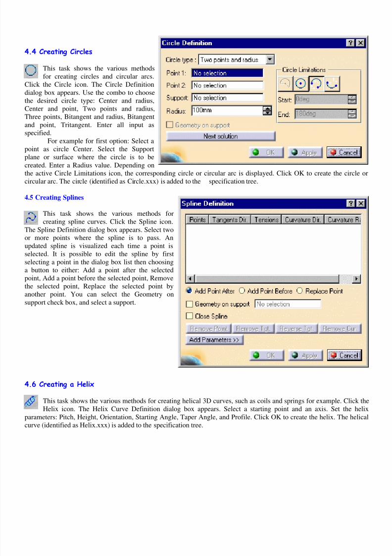
4.4 Creating Circles This task shows the various methods
for creating circles and circular arcs.
Click the Circle icon. The Circle Definition
dialog box appears. Use the combo to choose
the desired circle type: Center and radius,
Center and point, Two points and radius,
Three points, Bitangent and radius, Bitangent
and point, Tritangent. Enter all input as
specified.
For example for first option: Select a
point as circle Center. Select the Support
plane or surface where the circle is to be
created. Enter a Radius value. Depending on
the active Circle Limitations icon, the corresponding circle or circular arc is displayed. Click OK to create the circle or
circular arc. The circle (identified as Circle.xxx) is added to the specification tree.
4.5 Creating Splines
This task shows the various methods for
creating spline curves. Click the Spline icon.
The Spline Definition dialog box appears. Select two
or more points where the spline is to pass. An
updated spline is visualized each time a point is
selected. It is possible to edit the spline by first
selecting a point in the dialog box list then choosing
a button to either: Add a point after the selected
point, Add a point before the selected point, Remove
the selected point, Replace the selected point by
another point. You can select the Geometry onsupport check box, and select a support.
4.6 Creating a Helix This task shows the various methods for creating helical 3D curves, such as coils and springs for example. Click the
Helix icon. The Helix Curve Definition dialog box appears. Select a starting point and an axis. Set the helix
parameters: Pitch, Height, Orientation, Starting Angle, Taper Angle, and Profile. Click OK to create the helix. The helical
curve (identified as Helix.xxx) is added to the specification tree.

8/7/2019 4 Wire Frame and Surface Workbench
http://slidepdf.com/reader/full/4-wire-frame-and-surface-workbench 3/8
4.7 Creating Corners This task shows you how to create a corner between two curves or
between a point and a curve. Click the Corner icon. The Corner
Definition dialog box appears. Select two curves as reference element.
The corner will be created between these two references. Select the
Support surface. The resulting corner is a curve seen as an arc of circle
lying on a support place or surface. The reference elements must lie on
this support, as well as the center of the circle defining the corner. Enter
a Radius value. Several solutions may be possible, so click the Next
Solution button to move to another corner solution, or directly select the
corner you want in the geometry. You can select the Trim elements
check box if you want to trim and assemble the two reference elements
to the corner. Click OK to create the corner.
4.8 Creating Connect Curves This task shows how to create connecting curves between two existing curves. Click the Connect Curve icon. The
Connect Curve Definition dialog box appears. Select a first Point on a curve then a second Point on a second curve.
Use the combos to specify the desired Continuity type: Point, Tangency or Curvature. You can select the Trim elements
check box if you want to trim and assemble the two initial curves to the connect curve. Click OK to create the connect
curve.
4.9 Creating Spirals This task shows how to create curvesin the shape of spirals that is in 2D
plane. Click the Spiral icon. The Spiral
Curve Definition dialog box appears. Select
a supporting plane and the Center point for
the spiral. Specify a Reference direction
along which the Start radius value is
measured and from which the angle is
computed, when the spiral is defined by an
angle. Specify the Start radius value that is
the distance from the Center point, along
the Reference direction, at which the
spiral’s first revolution starts. Define thespirals Orientation that is the rotation
direction: clockwise or counter clockwise
8/7/2019 4 Wire Frame and Surface Workbench
http://slidepdf.com/reader/full/4-wire-frame-and-surface-workbench 4/8
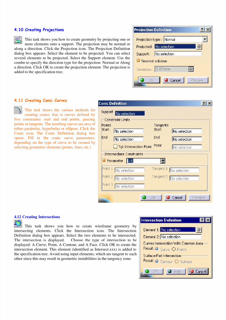
4.10 Creating Projections This task shows you how to create geometry by projecting one or
more elements onto a support. The projection may be normal or
along a direction. Click the Projection icon. The Projection Definition
dialog box appears. Select the element to be projected. You can select
several elements to be projected. Select the Support element. Use the
combo to specify the direction type for the projection: Normal or Along
a direction. Click OK to create the projection element. The projection is
added to the specification tree.
4.11 Creating Conic Curves This task shows the various methods for
creating conics that is curves defined by
five constraints: start and end points, passing
points or tangents. The resulting curves are arcs of
either parabolas, hyperbolas or ellipses. Click the
Conic icon. The Conic Definition dialog box
opens. Fill in the conic curve parameters,
depending on the type of curve to be created by
selecting geometric elements (points, lines, etc.)
4.12 Creating Intersections
This task shows you how to create wireframe geometry by
intersecting elements. Click the Intersection icon. The Intersection
Definition dialog box appears. Select the two elements to be intersected.
The intersection is displayed. Choose the type of intersection to be
displayed: A Curve, Point, A Contour, and A Face. Click OK to create the
intersection element. This element (identified as Intersect.xxx) is added to
the specification tree. Avoid using input elements, which are tangent to each
other since this may result in geometric instabilities in the tangency zone.

8/7/2019 4 Wire Frame and Surface Workbench
http://slidepdf.com/reader/full/4-wire-frame-and-surface-workbench 5/8
4.13 Creating Surfaces Wireframe and Surface allows you to model both simple and complex surfaces using techniques such as extruding,
lofting and sweeping. Two creation modes are available: either you create geometry with its history or not. Geometry with
no history is called a datum. For creating datum feature use create datum icon in tool menu icon.
4.13.1 Creating Extruded Surfaces
This task shows how to create a surface by extruding a profile along
a given direction. Click the Extrude icon. The Extruded Surface
Definition dialog box appears. Select the profile to be extruded and specify
the desired extrusion direction. Enter numerical values or use the graphic
manipulators to define the start and end limits of the extrusion. You can
click the Reverse Direction button to display the extrusion on the other side
of the selected profile. Click OK to create the surface
.
4.13.2 Creating Revolution Surfaces This task shows how to create a surface by revolving a planar
profile about an axis. Click the Revolve icon. The Revolution
Surface Definition dialog box appears. Select the Profile and a line
indicating the desired Revolution axis. Enter angle values or use the
graphic manipulators to define the angular limits of the revolution surface.
Click OK to create the surface. There must be no intersection between theaxis and the profile. If the profile is a sketch containing an axis, the latter
is selected by default as the revolution axis. You can select another
revolution axis simply by selecting a new line.
4.13.3 Creating Spherical Surfaces This task shows how to create surfaces in the shape of a sphere.
The spherical surface is based on a center point, an axis-system
defining the meridian & parallel curves orientation, and angular limits.Click the Sphere icon from the Extrude-Revolution toolbar. The Sphere
Surface Definition dialog box is displayed. Select the center point of the
sphere. Click Apply to preview the surface. Modify the Sphere radius
and the Angular Limits as required. Click OK to create the surface.
8/7/2019 4 Wire Frame and Surface Workbench
http://slidepdf.com/reader/full/4-wire-frame-and-surface-workbench 6/8
4.13.4 Creating Offset Surfaces This task shows how to create a surface by offsetting an existing surface. Click the Offset icon. The Offset Surface
Definition dialog box appears. Select the surface to be offset. Specify the offset by entering a value or using the
graphic manipulator. An arrow indicates the proposed direction for the offset. The offset surface is displayed normal to the
reference surface. Click Apply to previews the offset surface. Check the Both sides button to generate two offset surfaces,
one on each side of the reference surface. Click OK to create the surfaces.
4.13.5 Creating Swept Surfaces a) Using an Explicit Profile
This task shows how to create a swept surface that uses an explicit profile. You can create a swept surface by
sweeping out a profile in planes normal to a spine curve while taking other user-defined parameters (such as guide
curves and reference elements) into account. You can sweep an explicit profile: along one or two guide curves (in this case
the first guide curve is used as the spine), along one or two guide curves while respecting a spine. The profile is swept out
in planes normal to the spine.
This task shows how to create swept surfaces that use an explicit profile. Click the Sweep icon. The Swept Surface
Definition dialog box appears. Click the Explicit profile icon. Select the planar Profile to be swept out. Select a Guidecurve. If needed, select a Spine. If no spine is selected, the guide curve is implicitly used as the spine. You can define
relimiters (points or planes) in order to longitudinally reduce the domain of the sweep, if the swept surface is longer than
necessary for example. If needed, select a Second Guide.
If you want to control the position of the profile during the sweep, you can select a reference Surface. In the
Smooth sweeping section, you can check: the Angular correction option to smooth the sweeping motion along the reference
surface. Click OK to create the swept surface.
b) Using a Linear Profile This command is only available with the Generative Shape Design product. This task shows how to create swept
surfaces that use an implicit linear profile. Click the Sweep icon. The Swept Surface Definition dialog box appears. Click
the Line profile icon. The five possible cases are Two limits, Limit and middle, With reference surface, With reference
curve, With tangency surface, With draft direction. Click the Law button if you want a specific law to be applied rather thatthe absolute value. Click OK to create the swept surface. The surface (identified as Sweep.xxx) is added to the specification
tree.
c) Using a Circular Profile This command is only available with the Generative Shape Design product. This task shows how to create swept
surfaces that use an implicit circular profile. Click the Sweep icon. The Swept Surface Definition dialog box appears. Click
the Circle icon, and then use the combo to choose the subtype. The two following cases are possible using guide curves:
Select three guide curves, Select two guide curves and enter a Radius value. You can then choose between four possible
solutions by clicking the Other Solution button.
The two following cases are possible using a center curve: Select a Center Curve and a Reference angle curve,
Select a Center Curve and enter a Radius value. The two following cases are possible using a reference surface to which the
swept surface is to be tangent: Select two guide curves, and a reference surface to which the sweep is to be tangent. Selectguide curves, a reference surface to which the sweep is to be tangent, and enter a radius value. Click OK to create the swept
surface. The surface (identified as Sweep.xxx) is added to the specification tree.
d) Using a Conical Profile This command is only available with the Generative Shape Design product. This task shows how to create swept
surfaces that use an implicit conical profile, such as parabolas, hyperbolas or ellipses. Click the Sweep icon. The Swept
Surface Definition dialog box appears. Click the Conic icon, and then use the combo to choose the subtype. Two guides,
Three guides, Four guides, Five guides. Click OK to create the swept surface. The surface (identified as Sweep.xxx) is
added to the specification tree.
8/7/2019 4 Wire Frame and Surface Workbench
http://slidepdf.com/reader/full/4-wire-frame-and-surface-workbench 7/8
4.13.6 Creating Filling Surfaces This task shows how to create fill surfaces between a number of boundary segments. Click the Fill icon. The Fill
Surface Definition dialog box appears. Select curves or surface edges to form a closed boundary. You can edit the
boundary by first selecting an element in the dialog box list then choosing a button to either. Add a new element after or
before the selected one, Remove the selected element, Replace the selected element by another curve. Select a passing
point. This point should lie within the area delimited by the selected curves. If not, the results may be inconsistent. Click
OK to create the fill surface.
4.13.7 Creating Lofted Surfaces You can generate a lofted surface by sweeping one or two planar section curves along a computed or user-defined
spine. The surface can be made to respect one or more guide curves. Click the Loft icon. The Lofted Surface
Definition dialog box appears. Select one or two section curves. If needed, select one or more guide curves. In the Spine tab
page, select the Spine check box to use an automatically computed spine or select a curve to impose that curve as the spine.
The Relimitation tab lets you specify the loft relimitation type. You can choose to limit the loft only on the Start section,
only on the End section, on both, or on none. Use the Planar surface detection check button to automatically convert planar
surfaces into planes. Several coupling types are available, depending on the section configuration: Ratio, Tangency,
Tangency then curvature, Vertices. Click OK to create the lofted surface.
4.13.8 Creating Blended Surfaces This task shows how to create a blended surface that is a surface between two wireframe elements, taking a number
of constraints into account, such as tension, continuity, and so forth. Click the Blend icon. The Blend Definition
dialog box appears. Successively select the first curve and its support, then the second curve and its support. Set the
continuity type using the Basic tab. Activate the Trim first/second support option to trim them by the curve and assemble
them to the blend surface. You can also specify whether and where the blend boundaries must be tangent to the supports
boundaries: Both extremities, None, Start extremity, End extremity. Set the tension type using the Tension tab. It defines
the tension of the blend at its limits. Click OK. The surface (identified as Blend.xxx) is added to the specification tree.
4.14 Performing Operations on Shape Geometry Wireframe and Surface allows you to modify your design using techniques such as trimming, translating and
rotating.
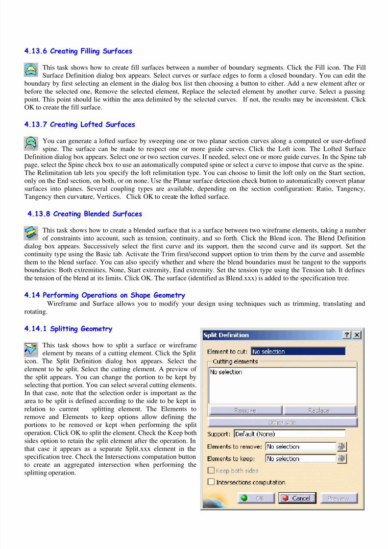
4.14.1 Splitting Geometry This task shows how to split a surface or wireframe
element by means of a cutting element. Click the Split
icon. The Split Definition dialog box appears. Select the
element to be split. Select the cutting element. A preview of
the split appears. You can change the portion to be kept by
selecting that portion. You can select several cutting elements.In that case, note that the selection order is important as the
area to be split is defined according to the side to be kept in
relation to current splitting element. The Elements to
remove and Elements to keep options allow defining the
portions to be removed or kept when performing the split
operation. Click OK to split the element. Check the Keep both
sides option to retain the split element after the operation. In
that case it appears as a separate Split.xxx element in the
specification tree. Check the Intersections computation button
to create an aggregated intersection when performing the
splitting operation.

8/7/2019 4 Wire Frame and Surface Workbench
http://slidepdf.com/reader/full/4-wire-frame-and-surface-workbench 8/8
4.14.2 Trimming Geometry This task shows how to trim two surfaces or two
wireframe elements. Click the Trim icon. The Trim
Definition dialog box appears. Select the two surfaces or two
wireframe elements to be trimmed. A preview of the trimmed
element appears. You can change the portion to be kept by
selecting that portion. You can also select the portions to be
kept by clicking the other side of element 1 and other side of
element 2 buttons. You are advised to use the Elements to
remove and Elements to keep options to define the portions to
be kept or removed. Click OK to trim the surfaces or
wireframe elements. The trimmed element (identified as
Trim.xxx) is added to the specification tree. Check the Result
simplification button to allow the system automatically to
reduce the number of faces in the resulting trim whenever
possible.
4.14.3 Boundary Curves This task shows how to create boundary curves. Click the Boundary icon. The Boundary Definition dialog box
appears. Select a Surface edge. The boundary curve is displayed according to the selected propagation type. You
can relimit the boundary curve by means of two elements, a point on the curve for example. Click OK to create the
boundary curve.
4.14.4 Extracting Geometry This task shows how to perform an extract from elements (curves, points, solids, and so forth.). This may beespecially useful when a generated element is composed of several non-connex sub-elements. Using the extract
capability you can generate separate elements from these sub-elements, without deleting the initial element. Select an edge
or the face of an element. The selected element is highlighted. Click the Extract icon. The Extract Definition dialog box is
displayed. Choose the Propagation type: Point continuity, No propagation, or Tangent continuity. Click OK to extract the
element. The extracted element (identified as Extract.xxx) is added to the specification tree.
4.14.5 Translating Geometry This task shows you how to translate one, or more, point, line or surface element. Click the Translate icon. The
Translate Definition dialog box appears. Select the element to be translated. Select the Vector Definition. Click OK
to create the translated element. The element (identified as Translate .xxx) is added to the specification tree.
4.14.6 Rotating Geometry This task shows you how to rotate geometry about an axis. Click the Rotate icon. The Rotate Definition dialog box
appears. Select the element to be rotated. Select a line as the rotation axis. Enter a value or use the Drag manipulator
to specify the rotation angle. Click OK to create the rotated element. Use the Repeat object after OK checkbox to create
several rotated surfaces. Click OK.
4.14.7 Performing a Symmetry on Geometry This task shows you how to transform geometry by means of a symmetry operation. Click the Symmetry icon. The
Symmetry Definition dialog box appears. Select the element to be transformed by symmetry. Select a point, line or
plane as reference element. Click OK to create the symmetrical element.