Embed Size (px)
Citation preview
UCRL-JC- 124024 PREPRINT
CON?+ 76 0 $/a3-- y5 '4
Scaling the TBNLC Collider Design to -
Higher Frequencies
T.L. Houck, D. Anderson,? S . Eylon,$ E. Henestroza,$ S.M. Lidia,f L.L. Reginato,? G.A. Westenskow, and S.S. Yu?
* ?Lawrence Berkeley National Laboratory $University of California, Davis
RECEIVED ocy 2 4 "a86
Geneva, Switzerland 0 S-T I
This paper was prepared for submittal to the
XVm International Linac Conference conference proceedings of the
August 26-30,1996
August 16, 1996
This is a preprint of a paper intended for publication in a journal or proceedings. Since changes may be made before publication, this preprint is made available with the understanding that it will not be cited or reproduced without the permission of the author.
A
11 A n v P P !J
LL642Iff V I A (m) &- f%STRIGUTION OF THIS DOCUMENT IS UNL!MlTED
Thisdocumentwaspreparedasanaccount ofworksponsoredbyanagencyof the United States Government Neither the United States Government nor the University ofCalifornianor any of theiremployees,makganywarmnty,express or implied, or assumes any legal liability of responsibility for the accuracy, completeness, or usefulness of any information, apparatus, product, or p r m disclosed, or represents that ik use would not infringe privately owned rights. Referencehereintoanyspedficcummercialproducts,prorhcebytrade name,trademark,manufacturer,or otherwjse,doesnotnecevarilyconstituteor imply its endorsement, recommendation, or favoring by the United States Government or the Univasity of California The views and opinions of authors srprrssed herein do not necessarily state or reflect those of the United States GovemmentortheUniversityofWornia,andshallnotbeusedforadvertisine: or product endorsement purposes.
.. . '
DISCLAIMER
3
?
. ...
DISCLAIMER
Portions of this document may be illegible in electronic image products. Images are produced from the best available original document.
SCALING THE TBNLC COLLIDER DESIGN TO HIGHER FREQUENCIES* T.L. Houck, D. Anderson?, S. Eylon?, E. Henestroza$, S.M.. Lidiat, LL. Reginatot, G A Westenskow, and S.S. Yu?
Lawrence Livermore National Laboratory, PO Box 808 Livermore, CA 94550, USA ?Lawrence Berkele National Laboratory, 1 Cyclotron Road Berkeley, CA 94720, USA
kniversity of California, Davis, CA 95616, USA
Abstract
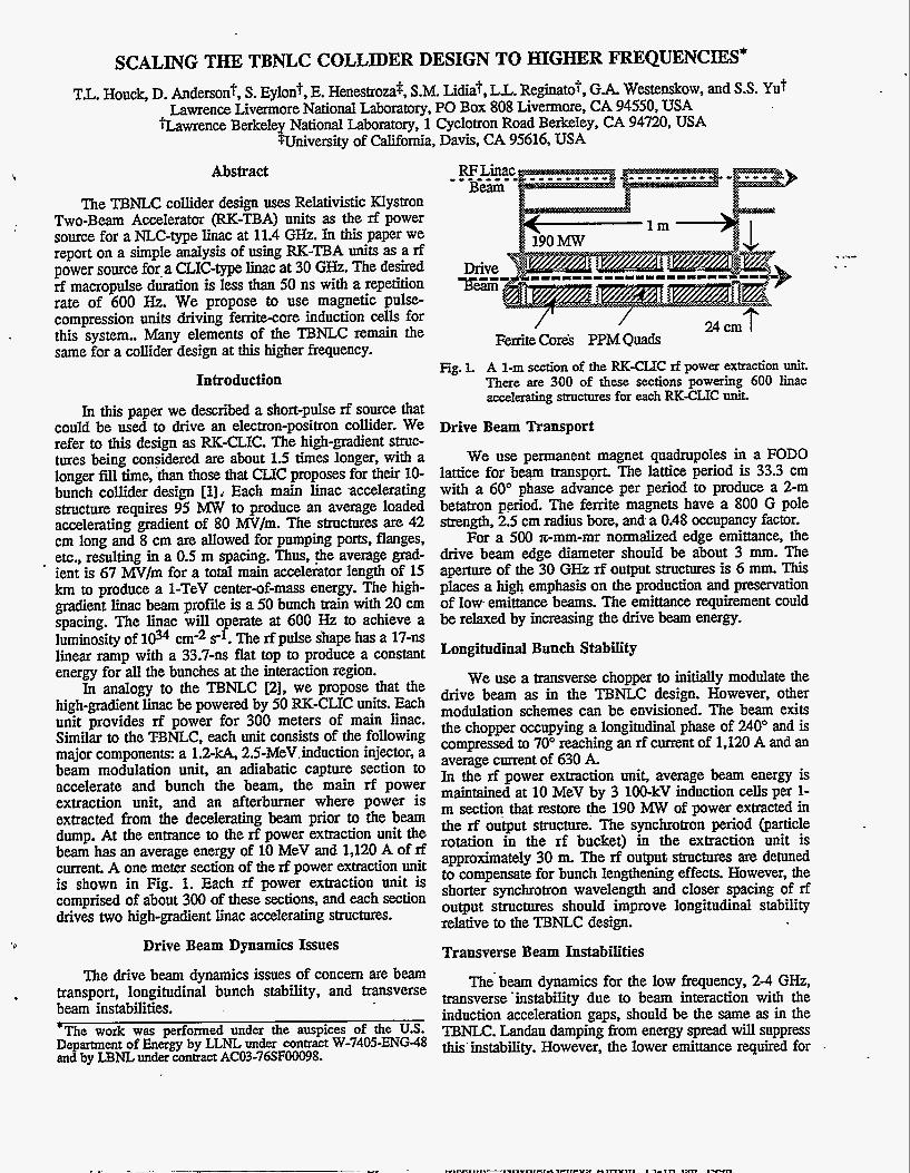
The TBNLC collider design uses Relativistic Klystron Two-Beam Accelerator (RK-TBA) units as the rf power source for a NLC-type linac at 11.4 GHz. In this paper we report on a simple analysis of using RK-TBA units as a rf power source f0r.a CLIC-type linac at 30 GHz. The desired rf macropulse duration is less than 50 ns with a repetition rate of 600 Hz. We propose to use magnetic pulse- compression units driving ferrite-core induction cells for this system.. Many elements of the TBNLC remain the same for a collider design at this higher frequency.
Introduction
In this paper we described a short-pulse rf source that could be used to drive an electron-positron collider. We refer to this design as RK-CLIC. The high-gradient struc- tures being considered are about 1.5 times longer, with a longer fill time, than those that CL.IC proposes for their 10- bunch collider design [l]; Each main linac .accelerating structure requires 95 Mw to produce an average loaded accelerating gradient of 80 W / m . The structures are 42 cm long and 8 cm are allowed for pumping ports, flanges, etc., resulting in a 0.5 m spacing. Thus, @e average grad-
' ient is 67 MV/m for a total main accelerator length of 15 km to produce a 1-TeV center-of-mass energy. The high- gradient linac beam profile is a 50 bunch train with 20 cm spacing. The linac will operate at 600 Hz to achieve a luminosity of 1034 cm-2 s-l. The rf pulse shape has a 17-ns linear ramp with a 33.7-ns flat top to produce a constant energy for all the bunches at the interaction region.
In analogy to the TBNLC [2], we propose that the high-gradient linac be powered by 50 RK-CLIC units. Each unit provides rf power for 300 meters of main linac. Similar to the 'IBNLC, each unit consists of the following major components: a 1.2-kA, 2.5-MeV.induction injector, a beam modulation unit, an adiabatic capture section to accelerate and bunch the beam, the main rf power extraction unit, and an afterburner where power is extracted from the decelerating beam prior to the beam dump. At the entrance to the rf power extraction unit the beam has an average energy of 10 MeV and 1,120 A of rf current. A one meter section of the rf power extraction unit is shown in Fig. 1. Each rf power extraction unit is comprised of about 300 of these sections, and each section drives two high-gradient linac accelerating structures.
,
.
b+ Drive Beam Dynamics Issues
The drive beam dynamics issues of concern are beam transport, longitudinal bunch stability, and transverse beam instabilities.
,
*The work was performed under the auspices of the US. Department of Energy by LLNL under mtract W-7405-ENG-48 and by BNL under contract ACO3-76SFOOO98.
RFLinac Beam
- - - - - - - -
24cm / Femte Cor& PPM Quads
Fig. 1. A 1-m section of the RK-CUC rf power extraction unit. There are 300 of these sections powering 600 linac accelerating structures for each RK-CLIC Unit.
Drive Beam Transport
We use permanent magnet quadrupoles in a FODO lattice for beam transport. The lattice period is 33.3 cm with a 60" phase advance per period to produce a 2-m betatron period. The ferrite magnets have a 800 G pole strength, 2.5 cm radius bore, and. a 0.48 occupancy factor.
For a 500 z-mm-mr normalized edge emittance, the drive beam edge diameter should be about 3 mm. The aperture of the 30 GHz rf output structures is 6 mm. This places a high emphasis on the production and preservation of low emittance beams. The emittance requirement could be relaxed by increasing the drive beam energy.
Longitudinal Bunch Stability
We use a transverse chopper to initially modulate the drive beam as in the TBNLC design. However, other modulation schemes can be envisioned. The beam exits the chopper occupying a longitudinal phase of 240" and is compressed to 70" reaching an rf current of 1,120 A and an average current of 630 A. In the rf power extraction unit, average beam energy is maintained at 10 MeV by 3 100-kV induction cells per 1- m section that restore the 190 MW of power extracted in the rf output structure. The synchrotron period (particle rotation in the rf bucket) in the extraction unit is approximately 30 m. The rf output structures are detuned to compensate for bunch lengthening effects. However, the shorter synchrotron wavelength and closer spacing of rf output structures should improve longitudinal stability relative to the TBNLC design.
Transverse Beam Instabilities
The beam dynamics for the low frequency, 24 GHz, ttansverse'instability due to beam interaction with the induction acceleration gaps, should be the Same as in the TBNLC. Landau damping from energy spread will suppress this'instability. However, the lower emittance required for .
the RK-CLIC drive beam may require reducing the transverse impedance of the induction gap.
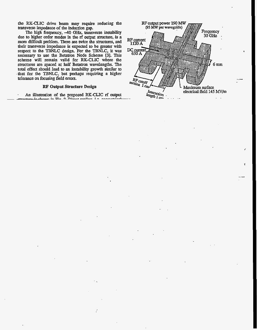
The high frequency, 4 0 GI-FZ, transverse instability due to higher order modes in the rf output structure, .is a more difficult problem. There are twice the structures, and their transverse impedance is expected to be greater with respect to the TBNLC design. For the TBNLC, it was necessary to use the Betatron Node Scheme [3]. This scheme will remain valid for RK-CLIC where the structures are spaced at half Betatron wavelengths. The total effect should lead to an instability growth similar to
.that for the TBNLC, but perhaps requiring a higher tolerance on focusing field errors.
RF Output Structure Design . An illustration of the proposed RK-CLIC rf output
~ d*mhrrn-;-hn..m &. EL.3--n:-..+ -....1:-.- : - .-..-..-2-z-
RF output power 190 (95 MW per wavegnide)
Y
d
mm
. ..-..
J
'I
. .....
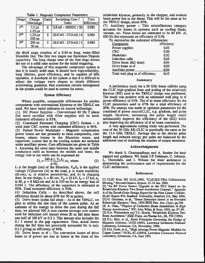
Table 1. Magnetic Compressor Parameters. I Stagel Charge I Gain1 Switching Core / I Core I
- I Discharge I I Tu& I Efficiency lSt I 7.5 US I 6 I 5.8 kG - 2605SC /2OI 0.983 I 1.25’Ll.s I 2 d I 1 . 2 5 ~ I 5 120.8 kG -2714AS /61 0.984
\ I 250ns I I I 3“ I 250ns I 5 126.8 kG-2714AS/11 0.980
I 50ns I I I v the third stage consists of a 0.84-m long, water-filled
Blumlein line. The first two stages use Strontium-Titanate capacitors. The long charge time of the f i t stage allows the use of a solid state system for the initial triggering.
The advantage of this magnetic compressor system is that it is totally solid state. It should have high-reliability, long lifetime, good efficiency, and be capable of kHz operation. A drawback of the system is that it is difficult to adjust the voltage wave shapes to obtain different accelerating gradients. Fast correction circuits interspersed in the system could be used to correct for errors.
System Efficiency
Where possible, comparable efficiencies for similar components with conventional klystrons or the TENLC are used. We have based estimates on current technology. (1) DC Power Supplies - Conventional 60 Hz 3 phase full wave rectifier with filter supplies will be used. Estimated efficiency is 93%. (2) Command Resonant Charging (CRC) System - A solid state CRC system with estimated efficiency is 96%. (3) Pulsed Power Modulator - Magnetic compression power losses are due primarily to three components, core losses, ohmic losses in the Blumlein water, and capacitors. Losses due to the cooling system are included under auxiliary power. Core efficiencies are given in Table 1. Assuming the same ratio between the outer and middle conductors radii as between the middle and inner, the energy loss in the water can be expressed as:
240 vo Io At, where UL = 0 6
(2) L is the length (cm) of the Blumlein, VdIo is the applied voltage (V)/current (A) to the load, p is water resistivity (a-cm), Er is relative permittivity, and A t is charging time. In our design, L = 84 cm, Vo = 25 kV, &, = 17 kA, Er is 80, p = 8 Mn-cm and At is 250 ns for an energy loss of 0.094 J. The efficiency of the capacitors is estimated at 98%. Total estimated efficiency is 92%. (4) Induction Cells - As described above, the cell efficiency should be about 65% for 50 ns pulses. ( 5 ) Drive beam (pulse fall time) - As in the TBNLC, we plan to utilize the rise time of the current pulse. As an estimate of the energy to drive the core during the fall time, we allowed 300 A core current (average core current used for induction cell losses) times 20 ns fall time times one half of 100 kV or 0.3 J. This amount also includes the 0.1 J stored in the gap capacitance. Thus, actual losses during the fall time not previously accounted for is only 0.2 J giving an efficiency of 94%. (6) Drive beam to rf - The conversion losses of drive beam to rf power are due to losses at the front of the
‘. . --
c
+
relativistic klystron, primarily in the chopper, and residual beam power lost in the dump. This will be the same as for the TBNLC design, about 90%. (7) Auxiliary power - This miscellaneous category accounts for losses in systems such as cooling fluids, vacuum, etc. These losses are estimated to be 80 ECW. At 600 Hz this represents an efficiency of 0.96.
To summarize the estimated efficiencies: CornDonen1 efficiency Power supplies 0.93 CRC 0.96 Modulator 0.92 Induction cells 0.65 . . _.. Drive beam (fall time) 0.94 Drive beam to rf 0.90 Auxiliarv po wer 0.96 Total wall plug to rf efficiency 0.43
Summary
A preliminary study for a 30 GHz linear collider using the CLIC high-gradient linac and scaling of the relativistic klystron (RK) used in the TBMLC design was performed. The result was positive with an estimated wall plug to rf power efficiency of 43%. The rf to beam efficiency for the CLIC parameters used is 678 for a total efficiency of 29%. No attempt was made to optimize parameters for the combined rf power source/CLIC, e.g. gradient, and pulse length. However, increasing the pulse length could substantially improve the efficiency of the (RK) while also improving the efficiency of rf to beam conversion.
A very approximate costing study was performed. The cost of the 30 GHz RK-CLIC is practically the same as for the 11.4 GHz TBNLC. Savings due to the shorter pulse length and reduced energy per pulse are balanced by the additional cost of doubling the number of output structures.
Acknowledgments
We thank S. Chattopadhyay and A. Sessler for their support and guidance. We thank J-P Delahaye, C. Johnson, L. Thorndahl, and I. Wilson for their assistance in determining the performance and rf requirements for the CLIC architecture.
References
[l] CLIC Note 295 22.01.1996, “CLIC/RK-TBA Collaboration Meeting,” Novotel-Geneva Airport, 15-16 Jan. 1996. [2] “An RF Power Source Upgrade to the NLC Based on the Relativistic-Klystron Two-Beam-Accelerator Concep&” Appendix A of the Zeroth-Order Design Report for the Next Linear CoUider, SLAC Report 474. Stanford University, Stanford CA. May 1996. [3] G. Giordano, et al., “Beam Dynamics Issues in an Extended Relativistic Klystron,” Proc. 1995 E E E Part. ACC. Cod., pp.740 141 A. Chao, “Physics of Collective Beam Instabilities in High Energy Accelerators,” Ny: John Wiley & Sons, 1993, pp. 87-89. [5] G.A. Westenskow and T.L. Houck, “Relativistic Klystron Two- Beam Accelerator,” ZEEE Trans. on Plasma Sci.. 22.750 (1994). [6] D.L. Birx, et al., Basic Principles Governing the Design of Mczgnetic Switches. UCID-18831, Lawrence Livennore National Laboratory, Livermore, CA, November, 1980. [7] E.G. Cook, et al., “High Average Power Magnetic Modular for Copper Lasers,” UCRLJC-105816. Lawrence Livermore National Laboratory, Livermore. CA, June 1991