Embed Size (px)
Citation preview

A LOOK AT SERVICE SAFETY
Servicing 37
9
4
SERVICING
I. Introduction. . . . . . . . . . . . . . . . . . . . . . . . . . . . . .38II. Servicing or Troubleshooting Water-Utilizing
Systems: Preventing Explosions . . . . . . . . . . . . .39III. Troubleshooting Chart . . . . . . . . . . . . . . . . . . . . .41IV. Identifying Compressor Electrical Problems. . . . .47V. Checking for Adequate Compressor Pumping . . .83VI. Is Your Compressor Eligible for Return
Under Warranty? . . . . . . . . . . . . . . . . . . . . . . . . .83

38 Chapter 4
I. Introduction
This chapter provides information to assist servicepersonnel in identifying and correcting compressorproblems. It provides a general troubleshootingchart that relates complaints or problems to possible
causes and solutions. This chapter also providesgreater detail about specific compressor problems.
For your safety, read and follow the “General ServiceSafety Precautions” on pages 2-7.
Before servicing...
THINK SAFETY➤ Disconnect ALL electrical power before removing
the protective terminal cover
➤ Never energize the system unless:• the protective terminal cover is securely
fastened, and• the compressor is properly connected to ground.
➤ Never reset a breaker or replace a fuse without first checking for a ground fault (also known as a short circuit to ground).
➤ Be alert for sounds of arcing (sizzling, sputtering or popping) inside the compressor. If you hear these sounds, IMMEDIATELY get away.

A LOOK AT SERVICE SAFETY
Servicing 39
II. Servicing or Troubleshooting Water-Utilizing Systems: Preventing Explosions
In certain water-utilizing refrigeration systems,water can leak into the refrigerant side of the system.This can lead to an explosion of system compo-nents, including but not limited to, the compressor.If such an explosion occurs, the resulting blast cankill or seriously injure anyone in the vicinity.
A. Systems at Risk of ExplosionWater-utilizing systems that have single-wall heatexchangers may present a risk of explosion. Suchsystems may include:
• water source heat pump/air conditioning sys-tems, and
• water cooling systems, such as icemakers, watercoolers, and juice dispensers.
Water-utilizing systems that have single-wall heatexchangers present a risk of explosion unless theyhave either:
• a high pressure cut-out which interrupts powerto ALL leads to the compressor, or
• an external pressure relief valve.
B. How an Explosion OccursIf the refrigerant tubing in the heat exchanger devel-ops a leak, water can enter the refrigerant side of thesystem. Water entering the refrigerant side can comein contact with live electrical connections in thecompressor causing a short circuit or a path toground. When this occurs, extremely high tempera-tures can result. The heat build-up creates steamvapor that can cause excessive pressure throughoutthe entire system. This system pressure can lead toan explosion of the compressor or other systemcomponents.
C. Service ProceduresIn light of the risk of explosion, be especially alertfor signs of water leaking into the refrigerant side ofthe system. Whenever servicing or troubleshooting awater-utilizing system, always check to see if it haseither a pressure relief valve or a high pressure cut-out as previously described. If the system does not
have at least one of these, DISCONNECT ALLELECTRICAL POWER and look for indicationsthat water has leaked into the refrigerant side of thesystem. These indications may include:
• Observation of or a report of a blown fuse ortripped circuit breaker.
• Signs that water has leaked to the outside ofthe system.
• Reports that the system has made gurgling orpercolating noises.
• A history of loss of refrigerant charge without aleak being found in the system. NOTE: Com-mon leak detection methods will not detect awater-to-refrigerant leak in the system’s heatexchanger(s).
• Observation of or a report of the compressorgiving off an unusual amount of heat.
If ANY of these indications are present, do the fol-lowing checks to determine if water has leaked intothe refrigerant side:
Step 1: Check for a Ground Fault (a Short to Ground)
Check the compressor for a ground fault (alsoknown as a short circuit to ground) using the proce-dure outlined in “Identifying Compressor ElectricalProblems” on page 47.
• If a ground fault does not exist, go to Step 2. • If a ground fault does exist, keep the power off.
WARNING! To avoid electric shock, electro-cution or terminal venting with ignition, donot energize a compressor that has a groundfault. Mark and red tag the compressor to indi-cate that there is a ground fault. Do not recon-nect the power leads. Tape and insulate eachpower lead separately. Proceed to Step 2. Donot replace the compressor or energize the sys-tem before performing Step 2.
Step 2: Check for Water in the SystemOnce the compressor is cool to the touch, open thesystem process valve slightly to see if any watercomes out of the system. WARNING! Opening thesystem process valve while the compressor is hotcan cause severe burns from steam coming out ofthe valve.
40 Chapter 4
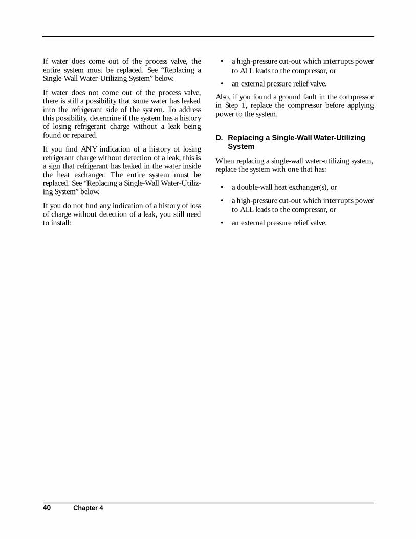
If water does come out of the process valve, theentire system must be replaced. See “Replacing aSingle-Wall Water-Utilizing System” below.
If water does not come out of the process valve,there is still a possibility that some water has leakedinto the refrigerant side of the system. To addressthis possibility, determine if the system has a historyof losing refrigerant charge without a leak beingfound or repaired.
If you find ANY indication of a history of losingrefrigerant charge without detection of a leak, this isa sign that refrigerant has leaked in the water insidethe heat exchanger. The entire system must bereplaced. See “Replacing a Single-Wall Water-Utiliz-ing System” below.
If you do not find any indication of a history of lossof charge without detection of a leak, you still needto install:
• a high-pressure cut-out which interrupts powerto ALL leads to the compressor, or
• an external pressure relief valve.
Also, if you found a ground fault in the compressorin Step 1, replace the compressor before applyingpower to the system.
D. Replacing a Single-Wall Water-Utilizing System
When replacing a single-wall water-utilizing system,replace the system with one that has:
• a double-wall heat exchanger(s), or
• a high-pressure cut-out which interrupts powerto ALL leads to the compressor, or
• an external pressure relief valve.

A LOOK AT SERVICE SAFETY
Servicing 41
III. Troubleshooting Chart
For your safety, read and follow the “General ServiceSafety Precautions” (on pages 2-7), as well as the ref-erenced troubleshooting procedures in this chart.The “General Service Safety Precautions” sectionprovides information on the following topics:
• Trained Personnel Only
• Terminal Venting and Electrocution
• Refrigerants and Other Chemicals
• Compressor Removal
• System Flushing, Purging, and Pressure Testingfor Leaks
• System Charging
• Prevention of Water-Utilizing System Explo-sions
• Start Capacitor Overheating
• System Evacuation
This Troubleshooting Chart is not designed toreplace the training required for a professional airconditioning/refrigeration service person, nor is itcomprehensive.
If you have any questions about returns under war-ranty, see “Is your Compressor Eligible for ReturnUnder Warranty?” on page 83.
Complaint Possible Causes Response
A Compressor will not start—no hum
1. System component not functioning properly:a. Control/contactor stuck in open
position.
b. Control off due to cold location.c. Thermostat not functioning properly.
a. Refer to the original equipment manufacturer (OEM) service information.
b. Same as “a”.c. Same as “a”.
2. Line disconnect switch open. Close the start switch or the disconnect switch.
3. Circuit breaker tripped or fuse open or removed.
Before resetting breaker or replacing fuse, see “Identifying Compressor Electrical Problems” on page 47.
4. Thermal protector not working properly. See “Identifying Compressor Electrical Problems” on page 47.
5. Wiring improper or loose. Check against wiring diagram and wire properly.
6. Compressor motor has a ground fault (also known as a short circuit to ground).
See “Identifying Compressor Electrical Problems” on page 47.

42 Chapter 4
B Compressor will not start—hums but trips on thermal protector
1. Improperly wired. Check against wiring diagram and wire properly.
2. Low voltage to compressor. Turn off system until proper voltage is restored.
3. System component, such as thermostat or control/contactor, not functioning properly.
Refer to the OEM service information.
4. Compressor electrical problems:a. Compressor motor has a winding
open or shorted.b. Start capacitor not working properly.c. Relay does not close.
a. See “Identifying Compressor Electrical Problems” on page 47.
b. Same as “a”.c. Same as “a”.
5. Liquid refrigerant in compressor. Add crankcase heater and a suction line accumulator. It is difficult to determine how liquid refrigerant got into the compressor. A crankcase heater along with a suction-line accumulator will prevent liquid refrigerant from getting into the compressor.
6. Internal mechanical trouble in compressor.
See “Checking for Adequate Compressor Pumping” on page 83.
C Compressor starts, but does not switch off of start winding
1. Improperly wired. Check against wiring diagram and wire properly.
2. Low voltage to compressor. Turn off system until proper voltage is restored.
3. Compressor electrical problems:a. Compressor motor has a winding
open or shorted.b. Relay failing to open.c. Run capacitor not working properly.
a. See “Identifying Compressor Electrical Problems” on page 47.
b. Same as “a”.c. Same as “a”.
4. Discharge pressure too high. If this is a water-utilizing system, see “Servicing or Troubleshooting Water-Utilizing Systems: Preventing Explosions” on page 39. Also refer to the OEM service information.
5. Internal mechanical trouble in compressor.
See “Checking for Adequate Compressor Pumping” on page 83.
Complaint Possible Causes Response
Troubleshooting Chart- continued

A LOOK AT SERVICE SAFETY
Servicing 43
D Compressor starts and runs, but short cycles on thermal protector
1. Too much current passing through thermal protector:a. Extra sources of current draw.
b. Compressor motor has winding shorted.
a. Check wiring diagram. Check for extra sources of current passing through thermal protector (such as fan motors, pumps.) Refer to the OEM service information.
b. See “Identifying Compressor Electrical Problems” on page 47.
2. Low voltage to compressor (single phase) or unbalanced voltage (three-phase).
Turn off system until proper voltage is restored.
3. Compressor electrical problems, such as thermal protector or run capacitor not working properly.
See “Identifying Compressor Electrical Problems” on page 47.
4. Discharge pressure too high. If this is a water-utilizing system, see “Servicing or Troubleshooting Water Utilizing Systems: Preventing Explosions” on page 39. Also, refer to the OEM service information.
5. Suction pressure too high. If this is a water-utilizing system, see “Servicing or Troubleshooting Water Utilizing Systems: Preventing Explosions” on page 39. Also, refer to the OEM service information.
6. Return gas too warm. If this is a water-utilizing system, see “Servicing or Troubleshooting Water Utilizing Systems: Preventing Explosions” on page 39. Also, refer to the OEM service information.
Complaint Possible Causes Response
Troubleshooting Chart- continued

44 Chapter 4
E Unit runs OK, but run cycle is shorter than normal (due to component(s) other than thermal protector)
1. System components, such as thermostat, control or contactor, not functioning properly.
Refer to the OEM service information.
2. High pressure cut-out due to:a. Insufficient air or water supply.b. Overcharge or refrigerant.c. Air in system.d. Water leak into refrigerant side of a
water-utilizing system.
a. Refer to the OEM service information.b. Same as “a”.c. Same as “a”.d. See “Servicing or Troubleshooting
Water Utilizing Systems: Preventing Explosions” on page 39. Also, refer to the OEM service information.
3. Low pressure cut-out due to:a. Liquid line solenoid leaking.b. Undercharge of refrigerant.c. Restriction in expansion device.
a. Refer to the OEM service information.b. Same as “a”.c. Same as “a”.
F Unit operates long or continuously
1. Undercharge of refrigerant. If this is a water-utilizing system, see “Servicing or Troubleshooting Water Utilizing Systems: Preventing Explosions” on page 39. Also, refer to the OEM service information.
2. System components, such as thermostat or contactor not functioning properly or control contacts stuck or frozen closed.
Refer to the OEM service information.
3. Refrigerated or air conditioned space has excessive load or poor insulation, or system inadequate to handle load.
Refer to the OEM service information.
4. Evaporator coil iced. Refer to the OEM service information.
5. Restriction in refrigeration system. Refer to the OEM service information.
6. Dirty condenser. Refer to the OEM service information.
7. Filter dirty. Refer to the OEM service information.
Complaint Possible Causes Response
Troubleshooting Chart- continued

A LOOK AT SERVICE SAFETY
Servicing 45
G Space or cabinet temperature too high
1. System problems, such as:a. control setting too highb. expansion valve too smallc. cooling coils too smalld. inadequate air circulation
a. Refer to the OEM service information.b. Same as “a”.c. Same as “a”.d. Same as “a“.
2. Water leak into refrigerant side of a water-utilizing system.
See “Servicing or Troubleshooting Water-Utilizing Systems: Preventing Explosions” on page 39. Also refer to the OEM service information.
H Suction line frosted or sweating
System problems, such as:a. expansion valve passing excess
refrigerant or is oversizedb. expansion valve stuck openc. evaporator fan not runningd. overcharge of refrigerant
a. Refer to the OEM service information.
b. Same as “a”.c. Same as “a”.d. Same as “a”.
I Liquid line frosted or sweating
System problems such as, restriction in dehydrator or strainer or liquid shut-off (king valve) partially closed.
Refer to the OEM service information.
Complaint Possible Causes Response
Troubleshooting Chart- continued

46 Chapter 4
J In water-utilizing systems, reports or observations of any of the following:
• system has made gurgling or percolating noises
• water has leaked to outside of the system.
• compressor giving off an unusual amount of heat.
Water leak into refrigerant side of a water utilizing system.
See “Servicing or Troubleshooting Water Utilizing Systems: Preventing Explosions” on page 39. Also refer to the OEM service information.
K System rattles or vibrates during operation.
Loose parts or mountings, tubing rattle, bent fan blade causing vibration, fan motor bearings worn, etc.
Refer to the OEM service information.
Complaint Possible Causes Response
Troubleshooting Chart- continued

A LOOK AT SERVICE SAFETY
Servicing 47
IV. Identifying Compressor Electrical Problems
This section describes procedures for checking thecompressor’s electrical circuits and components.Before doing so, follow the original equipmentmanufacturer’s service information (OEM) to makesure the system is getting proper voltage and that thecontrol, thermostat, and contactor are workingproperly. If you are servicing a water-utilizing sys-tem, see “Servicing or Troubleshooting Water-Utiliz-ing Systems: Preventing Explosions” on page 39.
Whenever you suspect that there is an electricalproblem with the compressor (for example, therehas been a tripped circuit breaker):
• FIRST, check for a ground fault (also known asa short circuit to ground) in the motor using amegohmmeter (“megger”) or a Hi-PotentialGround Tester (“Hi-Pot”) (Section A).
• SECOND, check the motor windings forproper continuity and resistance (Section B).
• THIRD, check the compressor’s electricalcomponents (Sections C and D).
When checking for electrical problems, it is impor-tant to follow all safety precautions (see warningbelow) and use the proper equipment and proce-dures.
Oil and refrigerant can spray out of the compres-sor if one of the terminal pins is ejected from thehermetic terminal. This can occur as a result of aground fault in the compressor. The oil and refrig-erant spray can be ignited by electricity and pro-duce flames that can lead to serious burns ordeath. If this spray is ignited it is called “terminalventing with ignition.”
To reduce the risk of electrocution, serious burnsor death from terminal venting with ignition:
➤ Disconnect ALL electrical power beforeremoving the protective terminal cover.
➤ Never energize the system unless:
• the protective terminal cover is securelyfastened, and
• the compressor is properly connected toground.
➤ Never reset a breaker or replace a fuse withoutfirst checking for a ground fault. An open fuseor tripped circuit breaker is a strong indicationof a ground fault.
➤ Be alert for sounds of arcing (sputtering orpopping) inside the compressor. If you hearthese sounds, IMMEDIATELY get away.
A. Checking for a Ground Fault (a Short to Ground)
Step 1: Disconnect PowerDisconnect all electrical power supplies to the sys-tem, making sure that all power legs are open.(NOTE: The system may have more than onepower supply.)
Step 2: Check for a Ground FaultRemove the protective terminal cover. If there is anyevidence of overheating at any lead, this is a goodindication that a compressor motor problem exists.At this time, do not replace or reattach leads or con-nectors that have been damaged by overheating.
Disconnect leads and/or remove all components(such as relays and capacitors) from the terminalpins. CAUTION: If a capacitor is present, using a20,000 ohm resistor, discharge it before removingit from the system to avoid damage to measuringdevices and risk of electric shock. When removinga current type relay, keep it upright.
Check the compressor for a ground fault usingeither a megohmmeter (“megger”) or a Hi-PotentialGround Tester (“Hi-Pot”). See Figure 4-4.WARNING! To reduce the risk of electrocution,always follow the manufacturers’ procedures andsafety rules when using these devices.
Connect one lead of either the megger or Hi-Pot tothe copper suction line. Connect the other lead toone of the terminal pins.
Repeat this procedure for the two remaining termi-nal pins. If the instrument indicates any resistanceless than 2 megohms between any pin and the hous-ing (copper suction line), a ground fault exists.
! WARNING

48 Chapter 4
WARNING! To avoid electric shock, electrocu-tion, and terminal venting with ignition do notenergize a compressor that has a ground fault.
If a ground fault exists, keep the power off andreplace the compressor. See “System Cleanup andCompressor Replacement After Compressor Fail-ure” on pages 104-107. If the compressor is notreplaced immediately, mark and red tag the com-
pressor to indicate there is a ground fault. Do notreconnect the power leads. Tape and insulate eachpower lead separately.
If a ground fault does not exist, leave the power offand all external components disconnected from theterminal pins. Check for continuity and properresistance using the procedure in Section B.
B. Checking for Continuity and Proper Resistance
If no ground fault has been detected using the pro-cedures in Section A, determine whether there is an
open or short circuit in the motor windings or if theheater element of the thermal protector is open. Usethe procedure in Table 4-1 to check single- and 3-phase motors.
Why use a megger or Hi-Pot? Tecumseh Products Company recom-mends checking for a ground fault onlywith a megger or Hi-Pot. A conventionalohmmeter will not reliably detect aground fault under certain circum-stances.
A megger is a special type of ohmmeterthat is capable of measuring very highresistances by using high voltages. A Hi-Pot is a device that uses high voltages tomeasure the flow of current across theinsulation. Unlike an ohmmeter, evenone that can measure millions of ohms,a megger or a Hi-Pot can detect a break-down in motor winding insulation beforethe motor fails. WARNING! To reducethe risk of electrocution, always followthe manufacturers’ procedures andsafety rules.
Figure 4-1. Top: Amprobe megohmmeter (commonly referred to as a “megger”). (Photo courtesy of Amprobe.) Bottom: A Slaughter Hi-Potential Ground Tester (commonly referred to as a “Hi-Pot”). (Photo courtesy of Slaughter.)

A LOOK AT SERVICE SAFETY
Servicing 49
Table 4-1: Checking for Proper Continuity and Resistance
Single Phase Compressor s 3-Phase Compressor s
Step 1: Allow Thermal Protector to Reset
When servicing single compressors with internal thermal protectors, be sure to allow time for the thermal protector to reset prior to starting these electrical wiring checks. For some compressors, the internal thermal protector may take as long as an hour to reset.
When servicing 3-phase compressors with internal thermal protectors, be sure to allow time for the thermal protector to reset prior to starting these electrical wiring checks. For some compressors, the internal thermal protector may take as long as an hour to reset.
Step 2: Check Continuity
Check the start winding by measuring continuity between terminal pins C and S. (See “Identification of Hermetic Terminal” on page 34). If there is no continuity, replace the compressor. See “System Cleanup and Compressor Replacement After Compressor Failure” on pages 104-107.
Check the run winding by measuring continuity between terminal pins C and R. If there is no continuity, replace the compressor.
Check the windings by measuring continuity between each pair of terminal pins: Leg1-Leg2, Leg2-Leg3, and Leg1-Leg3. If there is no continuity, replace the compressor. See “System Cleanup and Compressor Replacement After Compressor Failure” on pages 104-107.
Step 3: Measure the Resistance
Measure the resistance (ohms) between each pair of terminal pins: C and S, C and R, and S and R. Add the resistance between C and S to the resistance between C and R. This sum should equal the resistance found between S and R. A small deviation in this comparison is acceptable. Proper resistance may also be confirmed by comparing measured resistance to the resistance specifications for the specific compressor model. Call 1-800-211-3427 to request resistance specifications.If the resistance is not correct, replace the compressor. See “System Cleanup and Compressor Replacement After Compressor Failure” on pages 104-107. If the resistance is correct, leave the leads off and follow the instructions in the next section to check other compressor electrical components.
Measure the resistance (ohms) between each pair of terminal pins: Leg1-Leg2, Leg2-Leg3, and Leg1-Leg3. The resistance found between each of the pairs Leg1-Leg2, Leg2-Leg3, and Leg1-Leg3 should all be greater than zero and within about 10% of one another. Proper resistance may also be confirmed by comparing measured resistance to the resistance specifications for the specific compressor model. Call 1-800-211-3427 to request resistance specifications.If the resistance of Leg1-Leg2, Leg2-Leg3, and Leg1-Leg3 does not approximate the resistance of each other, then there is a short circuit. Replace the compressor. See “System Cleanup and Compressor Replacement After Compressor Failure” on pages 104-107.
If the resistance is correct and the 3-phase compressor has external components, leave the leads off and follow the instructions in Section D on page 81 to check other compressor electrical components. If the 3-phase compressor does not have any external components, the compressor must be replaced.
50 Chapter 4
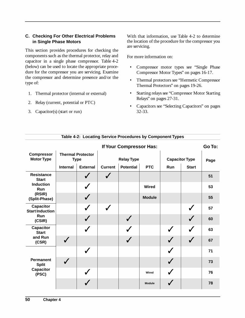
C. Checking For Other Electrical Problems in Single Phase Motors
This section provides procedures for checking thecomponents such as the thermal protector, relay andcapacitor in a single phase compressor. Table 4-2(below) can be used to locate the appropriate proce-dure for the compressor you are servicing. Examinethe compressor and determine presence and/or thetype of:
1. Thermal protector (internal or external)
2. Relay (current, potential or PTC)
3. Capacitor(s) (start or run)
With that information, use Table 4-2 to determinethe location of the procedure for the compressor youare servicing.
For more information on:
• Compressor motor types see “Single PhaseCompressor Motor Types” on pages 16-17.
• Thermal protectors see “Hermetic CompressorThermal Protectors” on pages 19-26.
• Starting relays see “Compressor Motor StartingRelays” on pages 27-31.
• Capacitors see “Selecting Capacitors” on pages32-33.
Table 4-2: Locating Service Procedures by Component Types
Compressor Motor Type
If Your Compressor Has: Go To:
Thermal Protector Type Relay Type Capacitor Type Page
Internal External Current Potential PTC Run Start
Resistance Start
InductionRun
(RSIR)(Split-Phase)
✓ ✓ 51
✓ Wired 53
✓ Module 55
Capacitor Start Induction
Run(CSIR)
✓ ✓ ✓ 57
✓ ✓ ✓ 60
Capacitor Start
and Run(CSR)
✓ ✓ ✓ ✓ 63
✓ ✓ ✓ ✓ 67
Permanent Split
Capacitor (PSC)
✓ ✓ 71
✓ ✓ 73
✓ Wired ✓ 76
✓ Module ✓ 78

A LOOK AT SERVICE SAFETY
Servicing 51
This RSIR (Split-Phase) Compressor Has the Following Components: The electrical system on this type of motor is shown
in Figure 4-2. The actual position of terminals onthe relay may be different than shown in Figure 4-2.Use the letters and/or numbers on the actual relay tolocate the terminals.
If replacement parts are needed, refer to the Tecum-seh Electrical Service Parts Guide Book for informa-tion on proper replacement parts, or call TecumsehProducts Company at 1-800-211-3427.
Thermal Protector
TypeRelay Type
Capacitor Type
Internal External Current Potential PTC Run Start
✓ ✓
Figure 4-2. RSIR compressor motor with external thermal protector and current type relay mounted on hermetic terminal.
*Other auxiliary devices may be attached. Disconnect any auxiliary devices in Step 2.
Line 1
Control
Relay — Current
External Thermal Protector
Sta
rt W
indi
ng
Mai
n W
indi
ng
Line 2
Ground
Compressor - UnitGround
FanMotor* S
C
R
M
S1

52 Chapter 4
Step 1: Before Continuing with Troubleshooting...
WARNING! All electric power should be disconnected andyou should have already made sure that the compressor doesnot have a ground fault (see “Checking for a Ground Fault”on pages 47-48). You should have also checked the windingsfor continuity and proper resistance (see “Checking for Conti-nuity and Proper Resistance” on pages 48-49), made sure thesystem is getting proper voltage, and that the control, thermo-stat, and contactor are working properly.
Step 2: Disconnect Fan Motor or Any Other Devices
If there is a fan motor or any other auxiliary device, open thecircuit for the fan motor or any other device.
Step 3: Check External Thermal Protector
Check for continuity across the thermal protector. If there is nocontinuity, then the thermal protector may be tripped. Wait atleast 5 minutes, then check continuity again. If there is still nocontinuity, replace the thermal protector.
Step 4: Check Current Relay Keep the relay upright. Check the relay by measuring continuitybetween:
a. Relay terminals 1 (or L) and S. If there is continuity,then the contacts are closed when they should be open.Replace the current relay.
b. Relay terminals 1 (or L) and M. If there is no continuity,replace the current relay.
Step 5: Replace Current Relay If all above tests prove satisfactory, there is no capillary restric-tion, and the unit still fails to operate properly, replace the relay.The new relay will eliminate any electrical problems which can-not be determined with above tests.
Step 6: Continue Troubleshooting If the new relay does not correct the problem, check for ade-quate compressor pumping as outlined in the procedure onpage 83.

A LOOK AT SERVICE SAFETY
Servicing 53
This RSIR (Split-Phase) Compressor Has the Following Components: The electrical system on this type of motor is shown
in Figure 4-3. The actual position of terminals onthe relay may be different than shown in Figure 4-3.Use the letters and/or numbers on the actual relay tolocate the terminals.
If replacement parts are needed, refer to the Tecum-seh Electrical Service Parts Guide Book for informa-tion on proper replacement parts, or call TecumsehProducts Company at 1-800-211-3427.
Thermal Protector
TypeRelay Type
Capacitor Type
Internal External Current Potential PTC Run Start
✓ ✓(wired)
Figure 4-3. RSIR compressor motor type with external thermal protector and wired-in PTC relay.
*Other auxiliary devices may be attached. Disconnect any auxiliary devices in Step 2.
4 T M Thermal Protector
Identified Conductor(115 Volt Only - Neutral)
Line 2
Line 1
Ground
Run Capacitor
Sta
rt W
indi
ng
Mai
n W
indi
ng
PTC Relay
Compressor - UnitGround
S
Alt. 3/4" Thermal Protector
Control
FanMotor*
R
C

54 Chapter 4
Step 1: Before Continuing with Troubleshooting...
WARNING! All electric power should be disconnected andyou should have already made sure that the compressor doesnot have a ground fault (see “Checking for a Ground Fault”on pages 47-48). You should have also checked the windingsfor continuity and proper resistance (see “Checking for Conti-nuity and Proper Resistance” on pages 48-49), made sure thesystem is getting proper voltage, and that the control, thermo-stat, and contactor are working properly.
Step 2: Disconnect Fan Motor or Any Other Devices
If there is a fan motor or any other auxiliary device, open thecircuit for the fan motor or any other device.
Step 3: Check Wired-in PTC Relay Check the relay by measuring continuity between the pin holeswhere the R and S pins on the compressor are inserted. If thereis no continuity, the relay may be open. Wait 3 minutes, thencheck continuity again. If there is still no continuity, replace therelay.
Step 4: Check External Thermal Protector
Check the external thermal protector by measuring continuitybetween the power-in terminal and the female C (common) ter-minal pin. If there is no continuity, the thermal protector maybe tripped. Wait at least 5 minutes, then check continuity again.If there is still no continuity, replace the thermal protector.
Step 5: Continue Troubleshooting If all above tests prove satisfactory and unit still fails to operateproperly, check for adequate compressor pumping as outlined inthe procedure on page 83.

A LOOK AT SERVICE SAFETY
Servicing 55
This RSIR (Split-Phase) Compressor Has the Following Components: The electrical system on this type of motor is shown
in Figure 4-4. The actual position of terminals onthe relay may be different than shown in Figure 4-4.Use the letters and/or numbers on the actual relay tolocate the terminals.
If replacement parts are needed, refer to the Tecum-seh Electrical Service Parts Guide Book for informa-tion on proper replacement parts, or call TecumsehProducts Company at 1-800-211-3427.
Thermal Protector
TypeRelay Type
Capacitor Type
Internal External Current Potential PTC Run Start
✓ ✓(module)
Figure 4-4. RSIR compressor motor type with external thermal protector and a PTC starting and protector package.
*Other auxiliary devices may be attached. Disconnect any auxiliary devices in Step 2.
Line 2
Ground
Line 1
Compressor - UnitGround
PTCRelay
PTC Starting and Protector Package
Thermal Protector
Sta
rt W
indi
ng
Mai
n W
indi
ng
N
C
S
R
FanMotor*
L
C2
C1
Control

56 Chapter 4
Step 1: Before Continuing with Troubleshooting...
WARNING! All electric power should be disconnected andyou should have already made sure that the compressor doesnot have a ground fault (see “Checking for a Ground Fault”on pages 47-48). You should have also checked the windingsfor continuity and proper resistance (see “Checking for Conti-nuity and Proper Resistance” on pages 48-49), made sure thesystem is getting proper voltage, and that the control, thermo-stat, and contactor are working properly.
Step 2: Disconnect Fan Motor or Any Other Devices
If there is a fan motor or any other auxiliary device, open thecircuit for the fan motor or any other device.
Step 3: Check External Thermal Protector
Check the external thermal protector by measuring continuitybetween C and L on the starting and protector package. If thereis no continuity, the thermal protector may be tripped. Wait atleast 5 minutes, then check continuity again. If there is still nocontinuity:
a. GE modules: replace the entire starting and protectorpackage.
b. TI modules: replace the thermal protector.
Step 4: Check Module PTC Relay Check the relay by measuring continuity between the startingand protector package pin holes where the R and S pins on thecompressor are inserted. If there is no continuity, the relay maybe open. Wait 3 minutes, then check continuity again. If there isstill no continuity, replace the protector package.
Step 5: Continue Troubleshooting If all above tests prove satisfactory and unit still fails to operateproperly, check for adequate compressor pumping as outlined inthe procedure on page 83.

A LOOK AT SERVICE SAFETY
Servicing 57
This CSIR Compressor Has the Following Components: The electrical system on this type of motor is shown
in Figure 4-5. The actual position of terminals onthe relay may be different than shown in Figure 4-5.Use the letters and/or numbers on the actual relay tolocate the terminals.
If replacement parts are needed, refer to the Tecum-seh Electrical Service Parts Guide Book for informa-tion on proper replacement parts, or call TecumsehProducts Company at 1-800-211-3427.
Thermal Protector Type
Relay TypeCapacitor
Type
Internal External Current Potential PTC Run Start
✓ ✓ ✓
Figure 4-5. CSIR compressor motor type with external thermal protector, current type relay mounted on hermetic terminal, and start capacitor.
*Other auxiliary devices may be attached. Disconnect any auxiliary devices in Step 2.
Line 2
Ground
Start Capacitor
External Thermal Protector
Sta
rt W
indi
ng
Mai
n W
indi
ngRelay - Current
Line 1
Compressor - UnitGround
Control C
S
S
MR
2
1
Fan*

58 Chapter 4
Step 1: Before Continuing with Troubleshooting...
WARNING! All electric power should be disconnected andyou should have already made sure that the compressor doesnot have a ground fault (see “Checking for a Ground Fault”on pages 47-48). You should have also checked the windingsfor continuity and proper resistance (see “Checking for Conti-nuity and Proper Resistance” on pages 48-49), made sure thesystem is getting proper voltage, and that the control, thermo-stat, and contactor are working properly.
Step 2: Disconnect Fan Motor or Any Other Devices
If there is a fan motor or any other auxiliary device, open thecircuit for the fan motor or any other device.
Step 3: Check External Thermal Protector
Check for continuity across the thermal protector. If there is nocontinuity, then the thermal protector may be tripped. Wait atleast 5 minutes, then check continuity again. If there is still nocontinuity, replace the thermal protector.
Step 4: Check Current Relay Keep the relay upright. Check the relay by measuring continuitybetween:
a. Relay terminals 1 and S. If there is continuity, then therelay contacts are closed when they should be open.Replace the current relay.
b. Relay terminals 2 and M. If there is no continuity,replace the current relay.
Step 5: Check Start Capacitor CAUTION: Using a 20,000 ohm resistor, discharge thecapacitor before removing it from the system to avoid damageto measuring devices and risk of electric shock. Disconnectthe start capacitor from the system. Use a capacitance meter tomeasure the capacitance. The capacitance value should be therated value minus 0% to plus 20%. If it is outside of this range,then the start capacitor needs to be replaced.
As an alternative, check the start capacitor by measuring conti-nuity between relay terminals 1 and 2:
a. Rx1 scale: If there is continuity, then the start capacitoris shorted and needs to be replaced.
b. Rx100,000 scale: If there is no needle deflection on ananalog meter or if a digital meter indicates infinite resis-tance, then the start capacitor is open and needs to bereplaced.
Possible reasons that a start capacitor is not working properlyinclude:
• Use of incorrect start capacitor. Replace with proper startcapacitor.
• The relay contacts are not working properly. Replacethe relay.

A LOOK AT SERVICE SAFETY
Servicing 59
Step 5: Check Start Capacitor-Continued
• Prolonged operation on start cycle due to low voltage.Determine if the line voltage is too low (less than 90% ofrated voltage).
• Prolonged operation on start cycle due to incorrectrelay. Replace with correct relay.
• Prolonged operation on start cycle due to starting loadtoo high. Refer to the OEM service information to usepump down arrangement, if necessary.
• Excessive short cycling. Short cycling can be caused byproblems with the compressor’s thermal protector or sys-tem components such as the thermostat, control, contac-tor, or high or low pressure cut-out. For more informationon troubleshooting the thermal protector, see Step 3. Fortroubleshooting the system components, refer to the OEMservice information.
Step 6: Replace Current Relay If all above tests prove satisfactory, there is no capillary restric-tion, and the unit still fails to operate properly, replace the relay.The new relay will eliminate any electrical problems which can-not be determined with above tests.
Step 7: Continue Troubleshooting If the new relay does not correct the problem, check for ade-quate compressor pumping as outlined in the procedure onpage 83.

60 Chapter 4
This CSIR Compressor Has the Following Components:
The electrical system on this type of motor is shownin Figure 4-6. The actual position of terminals onthe relay may be different than shown in Figure 4-6.Use the letters and/or numbers on the actual relay tolocate the terminals.
If replacement parts are needed, refer to the Tecum-seh Electrical Service Parts Guide Book for informa-tion on proper replacement parts, or call TecumsehProducts Company at 1-800-211-3427.
Thermal Protector
TypeRelay Type
Capacitor Type
Internal External Current Potential PTC Run Start
✓ ✓ ✓
*Other auxiliary devices may be attached. Disconnect any auxiliary devices in Step 2.
Figure 4-6. CSIR compressor motor type with external thermal protector, potential relay mounted remote, and start capacitor.
Relay - Potential
Compressor - UnitGround
Line 1
Line 2
Ground
Start Capacitor
Sta
rt W
indi
ng
Mai
n W
indi
ng
External Thermal Protector
Note: #4 and #6on relay aredummy terminals
Control
6
Fan*
R
C
S
5 2
14

A LOOK AT SERVICE SAFETY
Servicing 61
Step 1: Before Continuing with Troubleshooting...
WARNING! All electric power should be disconnected andyou should have already made sure that the compressor doesnot have a ground fault (see “Checking for a Ground Fault”on pages 47-48). You should have also checked the windingsfor continuity and proper resistance (see “Checking for Conti-nuity and Proper Resistance” on pages 48-49), made sure thesystem is getting proper voltage, and that the control, thermo-stat, and contactor are working properly.
Step 2: Disconnect Fan Motor or Any Other Devices
If there is a fan motor or any other auxiliary device, open thecircuit for the fan motor or any other device.
Step 3: Check External Thermal Protector
Check for continuity across the thermal protector. If there is nocontinuity, then the thermal protector may be tripped. Wait atleast 5 minutes, then check continuity again. If there is still nocontinuity, replace the thermal protector.
Step 4: Check Wiring Confirm that there is continuity between:
a. The power input terminal on the thermal protector and5 on relay.
b. The protector common lead wire and C.
Step 5: Check Potential Relay Before checking the relay, be sure it is mounted at the properposition. (See pages 28-32.) Check the potential relay by mea-suring continuity between:
a. Relay terminals 5 and 2. If there is no continuity, replacethe relay.
b. Relay terminals 2 and 1. If there is no continuity, thenthe contacts are open. Replace the relay.
Possible reasons that a relay is not working properly include:
• Use of incorrect relay. Replace with correct relay. • Line voltage is too high or low (greater than 110% or
less than 90% of rated voltage).• Excessive short cycling. Short cycling can be caused by
problems with the compressor’s thermal protector or sys-tem components such as the thermostat, control, contac-tor, or high or low pressure cut-out. For more informationon troubleshooting the thermal protector, see Step 3. Fortroubleshooting the system components, refer to the OEMservice information.
• Vibration due to loose relay mounting. Tighten relaymounting.
• Use of incorrect run capacitor. Replace with proper runcapacitor.
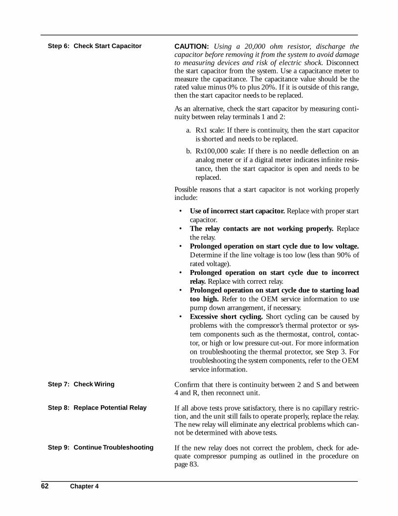
62 Chapter 4
Step 6: Check Start Capacitor CAUTION: Using a 20,000 ohm resistor, discharge thecapacitor before removing it from the system to avoid damageto measuring devices and risk of electric shock. Disconnectthe start capacitor from the system. Use a capacitance meter tomeasure the capacitance. The capacitance value should be therated value minus 0% to plus 20%. If it is outside of this range,then the start capacitor needs to be replaced.
As an alternative, check the start capacitor by measuring conti-nuity between relay terminals 1 and 2:
a. Rx1 scale: If there is continuity, then the start capacitoris shorted and needs to be replaced.
b. Rx100,000 scale: If there is no needle deflection on ananalog meter or if a digital meter indicates infinite resis-tance, then the start capacitor is open and needs to bereplaced.
Possible reasons that a start capacitor is not working properlyinclude:
• Use of incorrect start capacitor. Replace with proper startcapacitor.
• The relay contacts are not working properly. Replacethe relay.
• Prolonged operation on start cycle due to low voltage.Determine if the line voltage is too low (less than 90% ofrated voltage).
• Prolonged operation on start cycle due to incorrectrelay. Replace with correct relay.
• Prolonged operation on start cycle due to starting loadtoo high. Refer to the OEM service information to usepump down arrangement, if necessary.
• Excessive short cycling. Short cycling can be caused byproblems with the compressor’s thermal protector or sys-tem components such as the thermostat, control, contac-tor, or high or low pressure cut-out. For more informationon troubleshooting the thermal protector, see Step 3. Fortroubleshooting the system components, refer to the OEMservice information.
Step 7: Check Wiring Confirm that there is continuity between 2 and S and between4 and R, then reconnect unit.
Step 8: Replace Potential Relay If all above tests prove satisfactory, there is no capillary restric-tion, and the unit still fails to operate properly, replace the relay.The new relay will eliminate any electrical problems which can-not be determined with above tests.
Step 9: Continue Troubleshooting If the new relay does not correct the problem, check for ade-quate compressor pumping as outlined in the procedure onpage 83.
A LOOK AT SERVICE SAFETY
Servicing 63
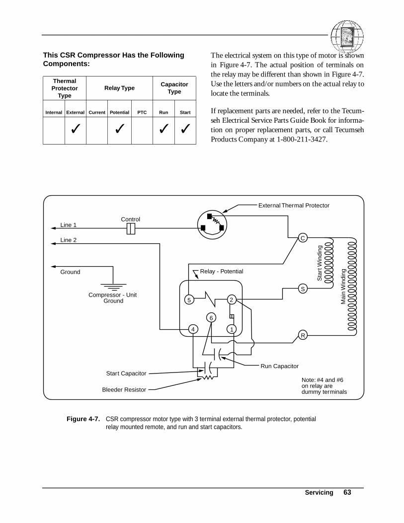
This CSR Compressor Has the Following Components:
The electrical system on this type of motor is shownin Figure 4-7. The actual position of terminals onthe relay may be different than shown in Figure 4-7.Use the letters and/or numbers on the actual relay tolocate the terminals.
If replacement parts are needed, refer to the Tecum-seh Electrical Service Parts Guide Book for informa-tion on proper replacement parts, or call TecumsehProducts Company at 1-800-211-3427.
Thermal Protector
TypeRelay Type
Capacitor Type
Internal External Current Potential PTC Run Start
✓ ✓ ✓ ✓
Figure 4-7. CSR compressor motor type with 3 terminal external thermal protector, potential relay mounted remote, and run and start capacitors.
Relay - Potential
Compressor - UnitGround
Line 1
Line 2
Ground
Sta
rt W
indi
ng
Mai
n W
indi
ng
Note: #4 and #6on relay aredummy terminals
Control
Start CapacitorRun Capacitor
Bleeder Resistor
External Thermal Protector
6
4 1
S
5 2
R
C

64 Chapter 4
Step 1: Before Continuing with Troubleshooting...
WARNING! All electric power should be disconnected andyou should have already made sure that the compressor doesnot have a ground fault (see “Checking for a Ground Fault”on pages 47-48). You should have also checked the windingsfor continuity and proper resistance (see “Checking for Conti-nuity and Proper Resistance” on pages 48-49), made sure thesystem is getting proper voltage, and that the control, thermo-stat, and contactor are working properly.
Step 2: Check Potential Relay Before checking the relay, be sure it is mounted at the properposition. (See pages 28-32.) Check the potential relay by mea-suring continuity between:
a. Relay terminals 5 and 2. If there is no continuity, replacethe relay.
b. Relay terminals 2 and 1. If there is no continuity, thenthe contacts are open. Replace the relay.
Possible reasons that a relay is not working properly include:
• Use of incorrect relay. Replace with correct relay. • Line voltage is too high or low (greater than 110% or
less than 90% of rated voltage). • Excessive short cycling. Short cycling can be caused by
problems with the compressor’s thermal protector or sys-tem components such as the thermostat, control, contac-tor, or high or low pressure cut-out. For more informationon troubleshooting the thermal protector, see Step 5. Fortroubleshooting the system components, refer to the OEMservice information.
• Vibration due to loose relay mounting. Tighten relaymounting.
• Use of incorrect run capacitor. Replace with proper runcapacitor.
Step 3: Check Run Capacitor CAUTION: Using a 20,000 ohm resistor, discharge thecapacitor before removing it from the system to avoid damageto measuring devices and risk of electric shock. Disconnectthe run capacitor from the system. Use a capacitance meter tocheck capacitor. Capacitance should be ±10% of the markedcapacitor value.
As an alternative, check the run capacitor by measuring conti-nuity across the capacitor terminals:
a. Rx1 scale: If there is continuity, then the run capacitor isshorted and needs to be replaced.

A LOOK AT SERVICE SAFETY
Servicing 65
Step 3: Check Run Capacitor-Continued
b. Rx100,000 scale: If there is no needle deflection on ananalog meter or if a digital meter indicates infinite resis-tance, then the run capacitor is open and needs to bereplaced.
Possible reasons that a run capacitor is not working properlyinclude:
• Use of incorrect run capacitor. Replace with proper runcapacitor.
• Line voltage is too high (greater than 110% of ratedvoltage).
Step 4: Check Start Capacitor CAUTION: Using a 20,000 ohm resistor, discharge thecapacitor before removing it from the system to avoid damageto measuring devices and risk of electric shock. Disconnectthe start capacitor from the system. Use a capacitance meter tomeasure the capacitance. The capacitance value should be therated value minus 0% to plus 20%. If it is outside of this range,then the start capacitor needs to be replaced.
As an alternative, check the start capacitor by measuring conti-nuity between relay terminals 1 and 4:
a. Rx1 scale: If there is continuity, then the start capacitoris shorted and needs to be replaced.
b. Rx100,000 scale: If there is no needle deflection on ananalog meter or if a digital meter indicates infinite resis-tance, then the start capacitor is open and needs to bereplaced.
Possible reasons that a start capacitor is not working properlyinclude:
• Use of incorrect start capacitor. Replace with proper startcapacitor.
• The relay contacts are not working properly. Replacethe relay.
• Prolonged operation on start cycle due to low voltage.Determine if the line voltage is too low (less than 90% ofrated voltage).
• Prolonged operation on start cycle due to incorrectrelay. Replace with correct relay.
• Prolonged operation on start cycle due to starting loadtoo high. refer to the OEM service information to usepump down arrangement, if necessary.

66 Chapter 4
Step 4: Check Start Capacitor-Continued
• Excessive short cycling. Short cycling can be caused byproblems with the compressor’s thermal protector or sys-tem components such as the thermostat, control, contac-tor, or high or low pressure cut-out. For more informationon troubleshooting the thermal protector, see Step 3. Fortroubleshooting the system components, refer to the OEMservice information.
Step 5: Check External Thermal Protector
Check for continuity across the thermal protector. If there is nocontinuity and Steps 1through 4 have been completed allowingthe thermal protector sufficient time to reset, replace the ther-mal protector.
Step 6: Check Wiring Confirm that there is continuity between 5 and C, 2 and S, and6 and R. Reconnect wiring.
Step 7: Replace Potential Relay If all above tests prove satisfactory, there is no capillary restric-tion, and the unit still fails to operate properly, replace the relay.The new relay will eliminate any electrical problems which can-not be determined with above tests.
Step 8: Continue Troubleshooting If the new relay does not correct the problem, check for ade-quate compressor pumping as outlined in the procedure onpage 83.

A LOOK AT SERVICE SAFETY
Servicing 67
This CSR Compressor Has the Following Components: The electrical system on this type of motor is shown
in Figures 4-8 and 4-9. The actual position of termi-nals on the relay may be different than shown inFigures 4-8 and 4-9. Use the letters and/or numberson the actual relay to locate the terminals.
If replacement parts are needed, refer to the Tecum-seh Electrical Service Parts Guide Book for informa-tion on proper replacement parts, or call TecumsehProducts Company at 1-800-211-3427.
Thermal Protector
TypeRelay Type
Capacitor Type
Internal External Current Potential PTC Run Start
✓ ✓ ✓ ✓
Figure 4-8. CSR compressor motor type with internal thermal protector without start winding protection, potential relay, and run and start capacitors.
Relay - Potential
Compressor - UnitGround
Note: #4 and #6on relay aredummy terminals
Internal Thermal Protector
Line 2
Start Capacitor
Bleeder Resistor
Run Capacitor
Ground
Line 1
Sta
rt W
indi
ng
Mai
n W
indi
ng
4
6
5 2
S
R1
C
Figure 4-9. CSR compressor motor type with internal thermal protector with start winding protection, potential relay, and run and start capacitors.
Relay - Potential
Compressor - UnitGround
Note: #4 and #6on relay aredummy terminals
Internal Thermal Protector
Line 2
Start Capacitor
Bleeder Resistor
Run Capacitor
Ground
Line 1
Sta
rt W
indi
ng
Mai
n W
indi
ng
46
5 2
S
R1
C

68 Chapter 4
Step 1: Before Continuing with Troubleshooting...
WARNING! All electric power should be disconnected andyou should have already made sure that the compressor doesnot have a ground fault (see “Checking for a Ground Fault”on pages 47-48). You should have also checked the windingsfor continuity and proper resistance (see “Checking for Conti-nuity and Proper Resistance” on pages 48-49), made sure thesystem is getting proper voltage, and that the control, thermo-stat, and contactor are working properly.
NOTE: The compressor housing MUST be at 130°F or less forthe following checks. This temperature can be read by Tempstikor is that temperature which will allow the hand to remain incontact with the compressor housing without discomfort.
Step 2: Check Internal Thermal Protector
Check for continuity across the thermal protector. If there is nocontinuity, then the internal thermal protector may be tripped.Wait for it to cool off and close. This may take more than anhour. Check continuity again. If there is replace the compressor.
Step 3: Check Run Capacitor CAUTION: Using a 20,000 ohm resistor, discharge thecapacitor before removing it from the system to avoid damageto measuring devices and risk of electric shock. Disconnectthe run capacitor from the system. Use a capacitance meter tocheck capacitor. Capacitance should be ±10% of the markedcapacitor value.
As an alternative, check the run capacitor by measuring conti-nuity across the capacitor terminals:
a. Rx1 scale: If there is continuity, then the run capacitor isshorted and needs to be replaced.
b. Rx100,000 scale: If there is no needle deflection on ananalog meter or if a digital meter indicates infinite resis-tance, then the run capacitor is open and needs to bereplaced.
Possible reasons that a run capacitor is not working properlyinclude:
• Use of incorrect run capacitor. Replace with proper runcapacitor.
• Line voltage is too high (greater than 110% of ratedvoltage).

A LOOK AT SERVICE SAFETY
Servicing 69
Step 4: Check Potential Relay Before checking the relay, be sure it is mounted at the properposition. (See pages 28-32.) Check the potential relay by mea-suring continuity between:
a. Relay terminals 5 and 2. If there is no continuity, replacethe relay.
b. Relay terminals 2 and 1. If there is no continuity, thenthe contacts are open. Replace the relay.
Possible reasons that a relay is not working properly include:
• Use of incorrect relay. Replace with correct relay. • Line voltage is too high or low (greater than 110% or
less than 90% of rated voltage).• Excessive short cycling. Short cycling can be caused by
problems with the compressor’s thermal protector or sys-tem components such as the thermostat, control, contac-tor, or high or low pressure cut-out. For more informationon troubleshooting the thermal protector, see Step 5. Fortroubleshooting the system components, refer to the OEMservice information.
• Vibration due to loose relay mounting. Tighten relaymounting.
• Use of incorrect run capacitor. Replace with proper runcapacitor.
Step 5: Check Start Capacitor CAUTION: Using a 20,000 ohm resistor, discharge thecapacitor before removing it from the system to avoid damageto measuring devices and risk of electric shock. Disconnectthe start capacitor from the system. Use a capacitance meter tomeasure the capacitance. The capacitance value should be therated value minus 0% to plus 20%. If it is outside of this range,then the start capacitor needs to be replaced.
As an alternative, check the start capacitor by measuring conti-nuity between relay terminals 1 and 4:
a. Rx1 scale: If there is continuity, then the start capacitoris shorted and needs to be replaced.
b. Rx100,000 scale: If there is no needle deflection on ananalog meter or if a digital meter indicates infinite resis-tance, then the start capacitor is open and needs to bereplaced.
Possible reasons that a start capacitor is not working properlyinclude:
• Use of incorrect start capacitor. Replace with proper startcapacitor.
• The relay contacts are not working properly. Replacethe relay.
70 Chapter 4
Step 5: Check Start Capacitor-Continued
• Prolonged operation on start cycle due to low voltage.Determine if the line voltage is too low (less than 90% ofrated voltage).
• Prolonged operation on start cycle due to incorrectrelay. Replace with correct relay.
• Prolonged operation on start cycle due to starting loadtoo high. Refer to the OEM service information to usepump down arrangement, if necessary.
• Excessive short cycling. Short cycling can be caused byproblems with the compressor’s thermal protector or sys-tem components such as the thermostat, control, contac-tor, or high or low pressure cut-out. For more informationon troubleshooting the thermal protector, see Step 3. Fortroubleshooting the system components, refer to the OEMservice information.
Step 6: Replace Potential Relay If all above tests prove satisfactory, there is no capillary restric-tion, and the unit still fails to operate properly, replace the relay.The new relay will eliminate any electrical problems which can-not be determined with above tests.
Step 7: Continue Troubleshooting If the new relay does not correct the problem, check for ade-quate compressor pumping as outlined in the procedure onpage 83.

A LOOK AT SERVICE SAFETY
Servicing 71
This PSC Compressor Has the Following Components:
The electrical system on this type of motor is shownin Figure 4-10. The actual position of terminals onthe relay may be different than shown in Figure 4-10. Use the letters and/or numbers on the actualrelay to locate the terminals.
If replacement parts are needed, refer to the Tecum-seh Electrical Service Parts Guide Book for informa-tion on proper replacement parts
Thermal Protector
TypeRelay Type
Capacitor Type
Internal External Current Potential PTC Run Start
✓ ✓
Figure 4-10. PSC compressor motor with external thermal protector and run capacitor.
Compressor - UnitGround
External Thermal Protector
Line 2
Run Capacitor
Ground
Line 1
Sta
rt W
indi
ng
Mai
n W
indi
ng
CControl
R
S

72 Chapter 4
Step 1: Before Continuing with Troubleshooting...
WARNING! All electric power should be disconnected andyou should have already made sure that the compressor doesnot have a ground fault (see “Checking for a Ground Fault”on pages 47-48). You should have also checked the windingsfor continuity and proper resistance (see “Checking for Conti-nuity and Proper Resistance” on pages 48-49), made sure thesystem is getting proper voltage, and that the control, thermo-stat, and contactor are working properly.
Step 2: Check Wiring Confirm that there is continuity between C and the protectorcommon lead wire.
Step 3: Check External Thermal Protector
Check for continuity across the thermal protector. If there is nocontinuity, then the thermal protector may be tripped. Wait atleast 5 minutes, then check continuity again. If there is still nocontinuity, replace the thermal protector.
Step 4: Check Run Capacitor CAUTION: Using a 20,000 ohm resistor, discharge thecapacitor before removing it from the system to avoid damageto measuring devices and risk of electric shock. Disconnectthe run capacitor from the system. Use a capacitance meter tocheck capacitor. Capacitance should be ±10% of the markedcapacitor value.
As an alternative, check the run capacitor by measuring conti-nuity across the capacitor terminals:
a. Rx1 scale: If there is continuity, then the run capacitor isshorted and needs to be replaced.
b. Rx100,000 scale: If there is no needle deflection on ananalog meter or if a digital meter indicates infinite resis-tance, then the run capacitor is open and needs to bereplaced.
Possible reasons that a run capacitor is not working properlyinclude:
• Use of incorrect run capacitor. Replace with proper runcapacitor.
• Line voltage is too high (greater than 110% of ratedvoltage).
Step 5: Reconnect Run Capacitor Reconnect the run capacitor into circuit at terminals S and R.(Marked terminal should go to R.)

A LOOK AT SERVICE SAFETY
Servicing 73
Step 6: Add Start Assist Kit If the compressor checks out satisfactory on all the above PSCtests, but still doesn’t operate, add proper start assist kit to pro-vide additional starting torque. See Figure 4-11 for proper wir-ing.
Step 7: Continue Troubleshooting If all above tests prove satisfactory and unit still fails to operateproperly, check for adequate compressor pumping as outlined inthe procedure on page 83.
Figure 4-11. PSC compressor motor with external thermal protector and an example start assist kit.
Compressor - UnitGround
External Thermal Protector
Line 2
Start Capacitor
Identified Conductor(115 Volt Only)
Bleeder Resistor
Run Capacitor
Ground
Line 1
Relay - Potential
Sta
rt W
indi
ng
Mai
n W
indi
ng
46
5 2
C
S
1
Control
R

74 Chapter 4
This PSC Compressor Has the Following Components:
The electrical system on this type of motor is shownin Figures 4-12 and 4-13.
If replacement parts are needed, refer to the Tecum-seh Electrical Service Parts Guide Book for informa-tion on proper replacement parts, or call TecumsehProducts Company at 1-800-211-3427.
Thermal Protector
TypeRelay Type
Capacitor Type
Internal External Current Potential PTC Run Start
✓ ✓
Figure 4-12. PSC compressor motor type with internal thermal protector without start winding protection and run capacitor.
Compressor - UnitGround
Internal Thermal Protector
Line 2
Run Capacitor
Ground
Line 1
Sta
rt W
indi
ng
Mai
n W
indi
ng
R
S
CControl
Figure 4-13. PSC compressor motor type with internal thermal protector with start winding protection and run capacitor.
Compressor - UnitGround
Internal Thermal Protector
Line 2
Run Capacitor
Ground
Line 1
Sta
rt W
indi
ng
Mai
n W
indi
ng
R
S
CControl
A LOOK AT SERVICE SAFETY
Servicing 75
Step 1: Before Continuing with Troubleshooting...
WARNING! All electric power should be disconnected and youshould have already made sure that the compressor does nothave a ground fault (see “Checking for a Ground Fault” onpages 47-48). You should have also checked the windings forcontinuity and proper resistance (see “Checking for Continuityand Proper Resistance” on pages 48-49), made sure the system isgetting proper voltage, and that the control, thermostat, and con-tactor are working properly.
NOTE: The compressor housing MUST be at 130°F or less forthe following checks. This temperature can be read by Tempstikor is that temperature which will allow the hand to remain incontact with the compressor housing without discomfort.
Step 2: Check Internal Thermal Protector
Check for continuity across the thermal protector. If there is nocontinuity, then the internal thermal protector may be tripped.Wait for it to cool off and close. This may take more than anhour. Check continuity again. If there is no continuity, replacethe compressor.
Step 3: Check Run Capacitor CAUTION: Using a 20,000 ohm resistor, discharge the capaci-tor before removing it from the system to avoid damage to mea-suring devices and risk of electric shock. Disconnect the runcapacitor from the system. Use a capacitance meter to checkcapacitor. Capacitance should be ±10% of the marked capacitorvalue.
As an alternative, check the run capacitor by measuring continu-ity across the capacitor terminals:
a. Rx1 scale: If there is continuity, then the run capacitor isshorted and needs to be replaced.
b. Rx100,000 scale: If there is no needle deflection on ananalog meter or if a digital meter indicates infinite resis-tance, then the run capacitor is open and needs to bereplaced.
Possible reasons that a run capacitor is not working properlyinclude:
• Use of incorrect run capacitor. Replace with proper runcapacitor.
• Line voltage is too high (greater than 110% of rated volt-age).
Step 4: Reconnect Run Capacitor Reconnect the run capacitor into circuit at terminals S and R.(Marked terminal should go to R.)
Step 5: Continue Troubleshooting If all above tests prove satisfactory and unit still fails to operateproperly, check for adequate compressor pumping as outlined inthe procedure on page 83.

76 Chapter 4
This PSC Compressor Has the Following Components: The electrical system on this type of motor is shown
in Figure 4-14. The actual position of terminals onthe relay may be different than shown in Figure 4-14. Use the letters and/or numbers on the actualrelay to locate the terminals.
If replacement parts are needed, refer to the Tecum-seh Electrical Service Parts Guide Book for informa-tion on proper replacement parts, or call TecumsehProducts Company at 1-800-211-3427.
Thermal Protector
TypeRelay Type
Capacitor Type
Internal External Current Potential PTC Run Start
✓ ✓(wired)
✓
Figure 4-14. PSC compressor motor type with external thermal protector, wired-in PTC relay, and run capacitor.
*Other auxiliary devices may be attached. Disconnect any auxiliary devices in Step 2.
Compressor - UnitGround
R
S
C
Line 2
Run Capacitor PTC Relay
Ground
Identified Conductor(115 Volt Only)
Line 1
Alt. 3/4" Thermal Protector
4TM Thermal Protector
Sta
rt W
indi
ng
Mai
n W
indi
ng
Control
Fan Motor*
A LOOK AT SERVICE SAFETY
Servicing 77
Step 1: Before Continuing with Troubleshooting...
WARNING! All electric power should be disconnected and youshould have already made sure that the compressor does nothave a ground fault (see “Checking for a Ground Fault” onpages 47-48). You should have also checked the windings for con-tinuity and proper resistance (see “Checking for Continuity andProper Resistance” on pages 48-49), made sure the system is get-ting proper voltage, and that the control, thermostat, and contac-tor are working properly.
Step 2: Disconnect Fan Motor or Any Other Devices
If there is a fan motor or any other auxiliary device, open the cir-cuit for the fan motor or any other device.
Step 3: Check Run Capacitor CAUTION: Using a 20,000 ohm resistor, discharge the capaci-tor before removing it from the system to avoid damage to mea-suring devices and risk of electric shock. Disconnect the runcapacitor from the system. Use a capacitance meter to checkcapacitor. Capacitance should be ±10% of the marked capacitorvalue.
As an alternative, check the run capacitor by measuring continuityacross the capacitor terminals:
a. Rx1 scale: If there is continuity, then the run capacitor isshorted and needs to be replaced.
b. Rx100,000 scale: If there is no needle deflection on ananalog meter or if a digital meter indicates infinite resis-tance, then the run capacitor is open and needs to bereplaced.
Possible reasons that a run capacitor is not working properlyinclude:
• Use of incorrect run capacitor. Replace with proper runcapacitor.
• Line voltage is too high (greater than 110% of rated volt-age).
Step 4: Check Wired-in PTC Relay Check the relay by measuring continuity between the pin holeswhere the R and S pins on the compressor are inserted. If there isno continuity, the relay may be open. Wait 3 minutes, then checkcontinuity again. If there is still no continuity, replace the relay.
Step 5: Check External Thermal Protector
Check the external thermal protector by measuring continuitybetween the power-in terminal and the female C (common) ter-minal pin. If there is no continuity, the thermal protector may betripped. Wait at least 5 minutes, then check continuity again. Ifthere is still no continuity, replace the thermal protector.
Step 6: Continue Troubleshooting If all above tests prove satisfactory and unit still fails to operateproperly, check for adequate compressor pumping as outlined inthe procedure on page 83.

78 Chapter 4
This PSC Compressor Has the Following Components: The electrical system on this type of motor is shown
in Figure 4-15. The actual position of terminals onthe relay may be different than shown in Figure 4-15. Use the letters and/or numbers on the actualrelay to locate the terminals.
If replacement parts are needed, refer to the Tecum-seh Electrical Service Parts Guide Book for informa-tion on proper replacement parts, or call TecumsehProducts Company at 1-800-211-3427.
Thermal Protector
TypeRelay Type
Capacitor Type
Internal External Current Potential PTC Run Start
✓ ✓(module)
✓(plug-in)
Figure 4-15. PSC compressor motor type with external thermal protector, PTC starting and protector package, and plug-in run capacitor.
*Other auxiliary devices may be attached. Disconnect any auxiliary devices in Step 2.
Line 2
Ground
Line 1
Compressor - UnitGround
PTCRelay
Plug-In Run Capacitor
PTC Starting and Protector Package
Thermal Protector
Sta
rt W
indi
ng
Mai
n W
indi
ng
N
C
S
R
FanMotor*
L
C2
C1
Control

A LOOK AT SERVICE SAFETY
Servicing 79
Step 1: Before Continuing with Troubleshooting...
WARNING! All electric power should be disconnected andyou should have already made sure that the compressor doesnot have a ground fault (see “Checking for a Ground Fault”on pages 47-48). You should have also checked the windingsfor continuity and proper resistance (see “Checking for Conti-nuity and Proper Resistance” on pages 48-49), made sure thesystem is getting proper voltage, and that the control, thermo-stat, and contactor are working properly.
Step 2: Disconnect Fan Motor or Any Other Devices
If there is a fan motor or any other auxiliary device, open thecircuit for the fan motor or any other device.
Step 3: Check Plug-in Run Capacitor CAUTION: Using a 20,000 ohm resistor, discharge thecapacitor before removing it from the system to avoid damageto measuring devices and risk of electric shock. Disconnectthe run capacitor from the system. Use a capacitance meter tocheck capacitor. Capacitance should be ±10% of the markedcapacitor value.
As an alternative, check the run capacitor by measuring conti-nuity across the capacitor terminals:
Check the run capacitor by measuring continuity:
a. Rx1 scale: If there is continuity, then the run capacitor isshorted and needs to be replaced.
b. Rx100,000 scale: If there is no needle deflection on ananalog meter or if a digital meter indicates infinite resis-tance, then the run capacitor is open and needs to bereplaced.
Possible reasons that a run capacitor is not working properlyinclude:
• Use of incorrect run capacitor. Replace with proper runcapacitor.
• Line voltage is too high (greater than 110% of ratedvoltage).
Step 4: Check External Thermal Protector
Check the external thermal protector by measuring continuitybetween C and L on the starting and protector package. If thereis no continuity, the thermal protector may be tripped. Wait atleast 5 minutes, then check continuity again. If there is still nocontinuity:
a. GE modules: replace the entire starting and protectorpackage.
b. TI modules: replace the thermal protector.

80 Chapter 4
Step 5: Check Module PTC Relay Check the relay by measuring continuity between the startingand protector package pin holes where the R and S pins on thecompressor are inserted. If there is no continuity, the relay maybe open. Wait 3 minutes, then check continuity again. If there isstill no continuity, replace the protector package.
Step 6: Continue Troubleshooting If all above tests prove satisfactory and unit still fails to operateproperly, check for adequate compressor pumping as outlined inthe procedure on page 83.

A LOOK AT SERVICE SAFETY
Servicing 81
D. Checking for Other Electrical Problems in 3-Phase Motors
The electrical system on this type of motor is shownin Figure 4-16. If replacement parts are needed, referto the Tecumseh Electrical Service Parts Guide Book
for information on proper replacement parts, or callTecumseh Products Company at 1-800-211-3427.
Figure 4-16. 3-phase motor with solid state protection system.
GroundingConductorGreen
T1
T2
T3
Compressor - Unit Ground Motor Sensors
From Protection Module (S1, S2)
Compressor Power FromContactor Terminals
Sensor Terminals
Connector Block
Motor Winding

82 Chapter 4
Step 1: Before Continuing with Troubleshooting...
WARNING! All electric power should be disconnected andyou should have already made sure that the compressor doesnot have a ground fault (see “Checking for a Ground Fault”on pages 47-48). You should have also checked the windingsfor continuity and proper resistance (see “Checking for Conti-nuity and Proper Resistance” on pages 48-49), made sure thesystem is getting proper voltage, and that the control, thermo-stat, and contactor are working properly.
Step 2: Allow Thermal Protector to Reset
When servicing 3-phase motors be sure to allow time for theinternal thermal protector to reset prior to starting these electri-cal wiring checks. For some compressors, the internal thermalprotector may take as long as an hour to reset.
Step 3: Check External Components Check the sensor terminals for continuity. If open, replace thesensor terminals.
Step 4: Continue Troubleshooting If all above tests prove satisfactory and unit still fails to operateproperly, check for adequate compressor pumping as outlined inthe procedure on page 83.
A LOOK AT SERVICE SAFETY
Servicing 83
V. Checking for Adequate Compressor Pumping
Before checking for adequate compressor pumping,you should have already checked for compressorelectrical problems as outlined in “Identifying Com-pressor Electrical Problems” starting on page 47.
To check for adequate pumping, connect servicegauges to system (add line taps if necessary). Then,turn on power to system. If the system has an ade-quate refrigeration charge, the compressor shouldmaintain at least 200 psig pressure differencebetween suction and discharge. If the compressordoes not pump adequately, it must be replaced withno further testing.
VI. Is Your Compressor Eligible for Return Under Warranty?
Authorized Tecumseh wholesalers are asked to testevery in-warranty compressor that is returned tothem. The Tecumseh factory tears down and exam-ines a representative sample of compressors returned
by authorized wholesalers and notes the reason forfailure.
In the field, it can be determined if a compressor iseligible for return under warranty by FIRST check-ing for electrical problems and then, checking foradequate compressor pumping. If the compressorpasses all electrical troubleshooting tests and pumpsadequately, the compressor is operating properly,and the problem lies elsewhere in the system.
A. Check the Compressor for Electrical Problems
Using the procedures in “Identifying CompressorElectrical Problems” starting on page 47, check thecompressor for electrical problems.
B. Check for Adequate Compressor Pumping
Connect service gauges to system (add line taps ifnecessary). Turn on power to system. If the systemhas an adequate refrigeration charge, the compressorshould maintain at least 200 psig pressure differencebetween suction and discharge. If compressor doesnot pump adequately, compressor must be replacedwith no further testing.

84 Chapter 4