Embed Size (px)
Citation preview
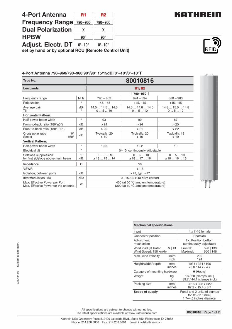
4-Port Antenna 790–960/790–960 90°/90° 15/15dBi 0°–10°/0°–10°T
Type No. 80010816Lowbands R1; R2R1; R2
790–960Frequency range MHz 790 – 862 824 – 894 880 – 960
Polarization ° +45, –45 +45, –45 +45, –45
Average gainTilt
dBi°
14.5 ... 14.5 ... 14.30 ... 5 ... 10
14.6 ... 14.8 ... 14.50 ... 5 ... 10
14.8 ... 15.0 ... 14.80 ... 5 ... 10
Horizontal Pattern:Half-power beam width ° 93 90 87
Front-to-back ratio (180°±0°) dB > 24 > 24 > 25
Front-to-back ratio (180°±30°) dB > 20 > 21 > 22
Cross polar ratio 0°Sector ±60° dB Typically: 20
> 10Typically: 20
> 10Typically: 18
> 10
Vertical Pattern:Half-power beam width ° 10.5 10.2 10
Electrical tilt ° 0–10, continuously adjustable
Sidelobe suppressionfor fi rst sidelobe above main beam
°TdB
0 ... 5 ... 10≥ 18 ... 15 ... 14
0 ... 5 ... 10≥ 18 ... 17 ... 16
0 ... 5 ... 10≥ 18 ... 16 ... 15
Impedance Ω 50
VSWR < 1.5
Isolation, between ports dB > 25, typ. > 27
Intermodulation IM3 dBc < –150 (2 x 43 dBm carrier)
Max. Effective Power per PortMax. Effective Power for the antenna W 400 (at 50 °C ambient temperature)
1200 (at 50 °C ambient temperature)
936.
4843
/b
Sub
ject
to a
ltera
tion.
4-Port AntennaFrequency RangeDual PolarizationHPBWAdjust. Electr. DTset by hand or by optional RCU (Remote Control Unit)
790–960
R2R2
790–960
R1R1
XX
90°90°
0°–10°0°–10°
80010816 Page 1 of 2
Mechanical specifi cations
Input 4 x 7-16 female
Connector position Rearside
Adjustmentmechanism
2x, Position bottomcontinuously adjustable
Wind load (at Rated Wind Speed: 150 km/h)
N | lbf Frontal: 590 | 133Maximal: 650 | 146
Max. wind velocity km/hmph
200124
Height/width/depth mminches
1934 / 374 / 10676.0 / 14.7 / 4.2
Category of mounting hardware H (Heavy)
Weight kglb
18 / 20 (clamps incl.)39.7 / 44.1 (clamps incl.)
Packing size mminches
2216 x 392 x 22287.2 x 15.4 x 8.7
Scope of supply Panel and 2 units of clamps for 42–115 mm |
1.7–4.5 inches diameter
Kathrein USA Greenway Plaza II, 2400 Lakeside Blvd., Suite 650, Richardson TX 75082Phone: 214.238.8800 Fax: 214.238.8801 Email: [email protected]
All specifications are subject to change without notice.The latest specifications are available at www.kathreinusa.com
38 |
1.5
44 |
1.7
106
| 4.2
121
| 4.8
67 | 2.6
188 | 7.4
288 | 11.3
374 | 14.7
2 1 3 4
Bottom viewAll dimensions in mm | inches
790-
96
0 Tilt Tilt 790-960
936.
4843
/b
Sub
ject
to a
ltera
tion.
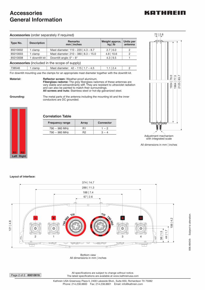
AccessoriesGeneral Information
72 | 2.8
2125
| 83
.7
1964
| 77
.3
1934
| 76
.0
Adjustment mechanismwith integrated scale
All dimensions in mm | inches
For downtilt mounting use the clamps for an appropriate mast diameter together with the downtilt kit.
Material: Refl ector screen: Weather-proof aluminum.Fiberglass radome: The grey fi berglass radomes of these antennas are very stable and extraordinarily stiff. They are resistant to ultraviolet radiation and can also be painted to match their surroundings.All screws and nuts: Stainless steel or hot-dip galvanized steel.
Grounding: The metal parts of the antenna including the mounting kit and the inner conductors are DC grounded.
Page 2 of 2 80010816
Layout of interface:
R1 R2Left Right
Correlation Table
Frequency range Array Connector
790 – 960 MHz R1 1 – 2
790 – 960 MHz R2 3 – 4
Accessories (order separately if required)
Type No. Description Remarksmm | inches
Weight approx.kg | lb
Units per antenna
85010002 1 clamp Mast diameter: 110 – 220 | 4.3 – 8.7 2.7 | 6.0 2
85010003 1 clamp Mast diameter: 210 – 380 | 8.3 – 15.0 4.8 | 10.6 2
85010008 1 downtilt kit Downtilt angle: 0° – 8° 4.3 | 9.5 1
Accessories (included in the scope of supply)
738546 1 clamp Mast diameter: 42 – 115 | 1.7 – 4.5 1.1 | 2.4 2
Kathrein USA Greenway Plaza II, 2400 Lakeside Blvd., Suite 650, Richardson TX 75082Phone: 214.238.8800 Fax: 214.238.8801 Email: [email protected]
All specifications are subject to change without notice.The latest specifications are available at www.kathreinusa.com

738546 Page 1 of 1
Mounting HardwareClamp Included in the Scope of Supply
936.
3920
/c
Sub
ject
to a
ltera
tion.
Suitable for mast diameter (mm)[inches]
42 – 115[1.65 – 4.53]
Antenna – mast distance (mm)[inches]
20 – 25[0.79 – 0.98]
Material of clamp and screws Hot-dip galvanized steel / stainless steel
Weight (kg)[lb]
1.1[2.43]
Please note: Kathrein does not recommend to use counter nuts.The additional nuts supplied are only meant as spares.
All dimensions in mm and [inches]
152 [5.98]
100 [3.94]40 [1.57]
72 [2.83]
35 [1.38]
64 [2.52]
125 [4.92]
40 [1
.57]
20–
25
[0.7
9–
0.98
]
42–115
[1.65–4.53]
M10 MA = 25 Nm
M8 MA = 20 Nm
20–25
[0.79–0.98]
Kathrein USA Greenway Plaza II, 2400 Lakeside Blvd., Suite 650, Richardson TX 75082Phone: 214.238.8800 Fax: 214.238.8801 Email: [email protected]
All specifications are subject to change without notice.The latest specifications are available at www.kathreinusa.com
Page 1 of 2
936.
4037
/a
Sub
ject
to
alte
ratio
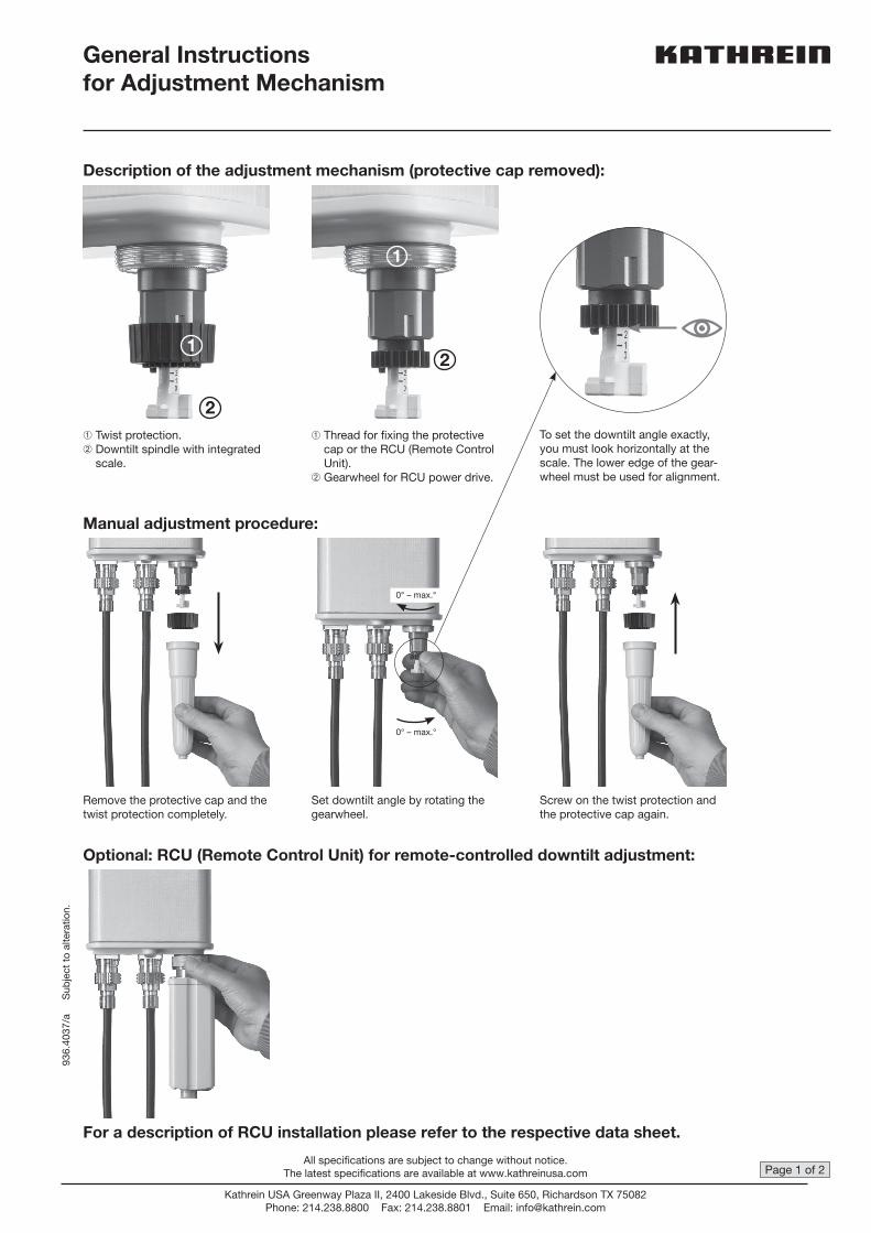
n.General Instructionsfor Adjustment Mechanism
Description of the adjustment mechanism (protective cap removed):
Manual adjustment procedure:
Optional: RCU (Remote Control Unit) for remote-controlled downtilt adjustment:
For a description of RCU installation please refer to the respective data sheet.
Remove the protective cap and the twist protection completely.
➀ Twist protection.➁ Downtilt spindle with integrated
scale.
➀ Thread for fi xing the pro tectivecap or the RCU (Remote ControlUnit).
➁ Gearwheel for RCU power drive.
To set the downtilt angle exactly, you must look horizontally at the scale. The lower edge of the gear-wheel must be used for alignment.
Set downtilt angle by rotating the gearwheel.
Screw on the twist protection and the protective cap again.
0° – max.°
0° – max.°
1
2
2
1
Kathrein USA Greenway Plaza II, 2400 Lakeside Blvd., Suite 650, Richardson TX 75082Phone: 214.238.8800 Fax: 214.238.8801 Email: [email protected]
All specifications are subject to change without notice.The latest specifications are available at www.kathreinusa.com
Page 2 of 2
936.
4037
/a
Sub
ject
to
alte
ratio
n.
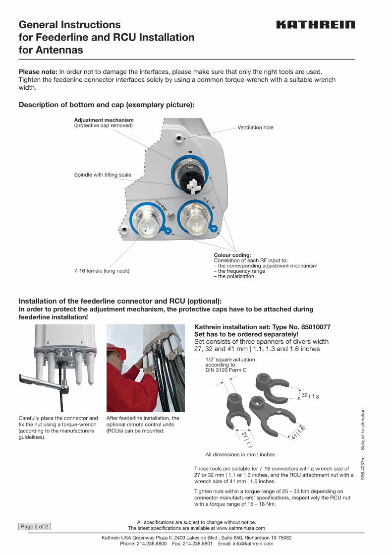
Installation of the feederline connector and RCU (optional):In order to protect the adjustment mechanism, the protective caps have to be attached during feederline installation!
Carefully place the connector and fi x the nut using a torque-wrench (according to the manufacturers guidelines).
After feederline installation, the optional remote control units (RCUs) can be mounted.
These tools are suitable for 7-16 connectors with a wrench size of 27 or 32 mm | 1.1 or 1.3 inches, and the RCU attachment nut with a wrench size of 41 mm | 1.6 inches.
Tighten nuts within a torque range of 25 – 33 Nm depending on connector manufacturers’ specifi cations, respectively the RCU nut with a torque range of 15 – 18 Nm.
Kathrein installation set: Type No. 85010077Set has to be ordered separately!Set consists of three spanners of divers width27, 32 and 41 mm | 1.1, 1.3 and 1.6 inches
32 | 1.3
41 | 1
.627 | 1.1
1/2˝ square actuationaccording toDIN 3120 Form C
All dimensions in mm | inches
Colour coding:Correlation of each RF input to:– the corresponding adjustment mechanism– the frequency range– the polarization
Ventilation hole
Spindle with tilting scale
7-16 female (long neck)
Adjustment mechanism(protective cap removed)
General Instructions for Feederline and RCU Installation for Antennas
Please note: In order not to damage the interfaces, please make sure that only the right tools are used. Tighten the feederline connector interfaces solely by using a common torque-wrench with a suitable wrench width.
Description of bottom end cap (exemplary picture):
Kathrein USA Greenway Plaza II, 2400 Lakeside Blvd., Suite 650, Richardson TX 75082Phone: 214.238.8800 Fax: 214.238.8801 Email: [email protected]
All specifications are subject to change without notice.The latest specifications are available at www.kathreinusa.com