Embed Size (px)
Citation preview

8/3/2019 4 Modified)
http://slidepdf.com/reader/full/4-modified 1/26
IE433 CAD/CAM
Computer Aided Design andComputer Aided Manufacturing
Part-4
Computer Graphics-CAD Software
Industrial Engineering Program
King Saud University

8/3/2019 4 Modified)
http://slidepdf.com/reader/full/4-modified 2/26
CAD Software
CAD software can be divided based upon thetechnology used:
1. 2-D drawing. Its applications include,
· mechanical part drawing
· printed-circuit board design and layout· facilities layout
· cartography
2. Basic 3-D drawing (such as wire-frame modelling)
3. Sculptured surfaces (such as surface modelling)4. 3-D solid modelling
5. Engineering analysis

8/3/2019 4 Modified)
http://slidepdf.com/reader/full/4-modified 3/26
Geometric Modeling
Geometric modelling refers to a set of
techniques concerned mainly with
developing efficient representations of geometric aspects of a design. Therefore,
geometric modelling is a fundamental part
of all CAD tools.

8/3/2019 4 Modified)
http://slidepdf.com/reader/full/4-modified 4/26
Geometric modeling is the basic of manyapplications such as:
•Mass property calculations.
• Mechanism analysis.
• Finite-element modelling.
•NC programming.
Requirements of geometric modelling include:
• Completeness of the part representation.
•
The modelling method should be easy to use by designers.• Rendering capabilities (which means how fast the entities
can be accessed and displayed by the computer).

8/3/2019 4 Modified)
http://slidepdf.com/reader/full/4-modified 5/26
Geometric Modeling Approaches
The basic geometric modelling approaches available to
designers on CAD/CAM systems are:
1. Wire-frame modeling.2. Surface modeling.
3. Solid modeling.

8/3/2019 4 Modified)
http://slidepdf.com/reader/full/4-modified 6/26
Wire-frame Modeling
Wire-frame modelling uses points and curves
(i.e. lines, circles, arcs), and so forth todefine objects.
The user uses edges and vertices of the part
to form a 3-D object
Wire-frame model part

8/3/2019 4 Modified)
http://slidepdf.com/reader/full/4-modified 7/26
Example

8/3/2019 4 Modified)
http://slidepdf.com/reader/full/4-modified 8/26
Surface Modeling
Surface modeling is more sophisticated than wireframe modeling
in that it defines not only the edges of a 3D object, but also its
surfaces.
In surface modeling, objects are defined by their bounding faces.
Examples

8/3/2019 4 Modified)
http://slidepdf.com/reader/full/4-modified 9/26
SURFACE ENTITIES
Similar to wireframe entities, existing CAD/CAM
systems provide designers with both analytic andsynthetic surface entities.
Analytic entities include :
•Plane surface,
•
Ruled surface,•Surface of revolution, and
•Tabulated cylinder.
Synthetic entities include
•The bicubic Hermite spline surface,•B-spline surface,
•Rectangular and triangular Bezier patches,
•Rectangular and triangular Coons patches, and
•Gordon surface.

8/3/2019 4 Modified)
http://slidepdf.com/reader/full/4-modified 10/26
Plane surface. This is the simplest surface. It requires
three noncoincident points to define an infinite plane.

8/3/2019 4 Modified)
http://slidepdf.com/reader/full/4-modified 11/26
Ruled (lofted) surface. This is a linear surface. It interpolates
linearly between two boundary curves that define the surface
(rails). Rails can be any wireframe entity. This entity is ideal to
represent surfaces that do not have any twists or kinks.

8/3/2019 4 Modified)
http://slidepdf.com/reader/full/4-modified 12/26
Surface of revolution. This is an axisymmetric surface
that can model axisymmetric objects. It is generated by
rotating a planar wireframe entity in space about the axisof symmetry a certain angle.

8/3/2019 4 Modified)
http://slidepdf.com/reader/full/4-modified 13/26
Tabulated cylinder. This is a surface generated by
translating a planar curve a certain distance along a
specified direction (axis of the cylinder).

8/3/2019 4 Modified)
http://slidepdf.com/reader/full/4-modified 14/26
Bezier surface. This is a surface that approximates given
input data. It is different from the previous surfaces in
that it is a synthetic surface. Similarly to the Bezier curve,it does not pass through all given data points. It is a
general surface that permits, twists, and kinks . The
Bezier surface allows only global control of the surface.

8/3/2019 4 Modified)
http://slidepdf.com/reader/full/4-modified 15/26
B-spline surface. This is a surface that can approximate
or interpolate given input data (Fig. 6-9). It is a synthetic
surface. It is a general surface like the Bezier surface butwith the advantage of permitting local control of the
surface.

8/3/2019 4 Modified)
http://slidepdf.com/reader/full/4-modified 16/26
Solid Modeling
Solid models give designers a completedescriptions of constructs, shape, surface, volume,
and density.

8/3/2019 4 Modified)
http://slidepdf.com/reader/full/4-modified 17/26
In CAD systems there are a number of representation schemes for solid modeling
include:
•Primitive creation functions.
•Constructive Solid Geometry (CSG)
•Sweeping
•Boundary Representation (BREP)
8/3/2019 4 Modified)
http://slidepdf.com/reader/full/4-modified 18/26
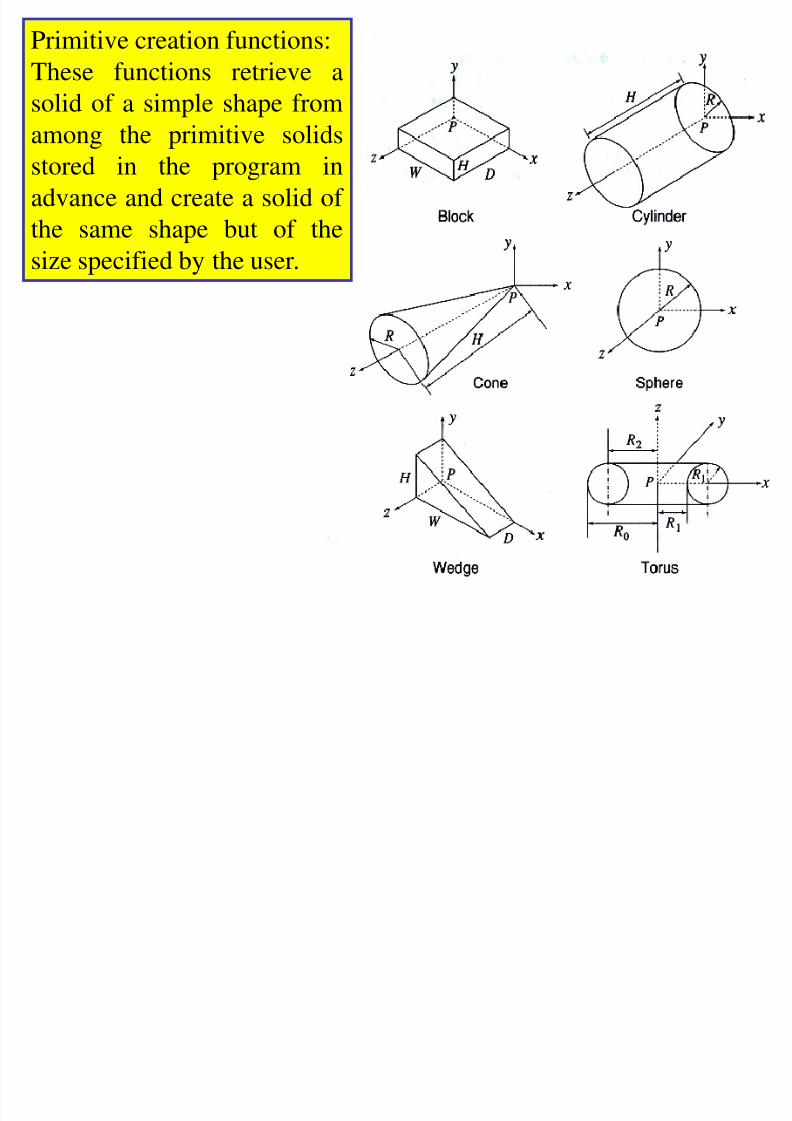
Primitive creation functions:
These functions retrieve a
solid of a simple shape from
among the primitive solidsstored in the program in
advance and create a solid of
the same shape but of the
size specified by the user.
8/3/2019 4 Modified)
http://slidepdf.com/reader/full/4-modified 19/26
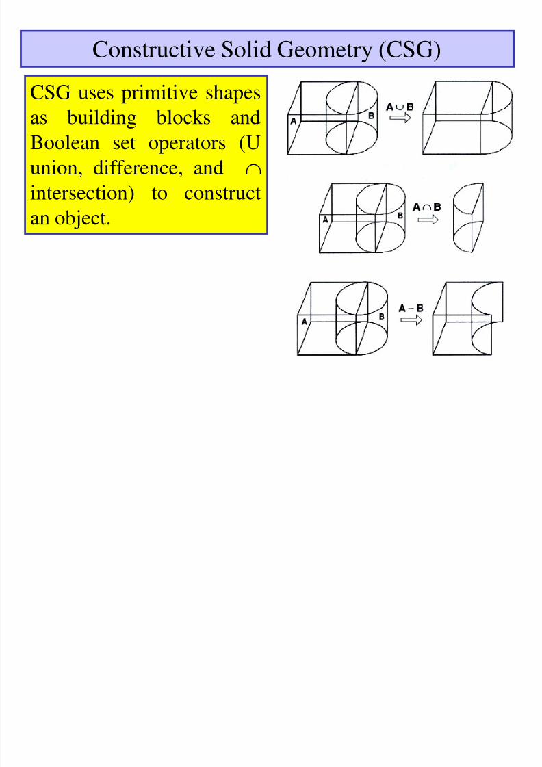
Constructive Solid Geometry (CSG)
CSG uses primitive shapesas building blocks and
Boolean set operators (U
union, difference, and
intersection) to constructan object.

8/3/2019 4 Modified)
http://slidepdf.com/reader/full/4-modified 20/26
Example

8/3/2019 4 Modified)
http://slidepdf.com/reader/full/4-modified 21/26
Sweeping
Sweeping Sweeping is
a modeling function in
which a planar closed
domain is translated or
revolved to form a
solid. When the planardomain is translated,
the modeling activity is
called translational
sweeping; when the
planar region isrevolved, it is called
swinging, or rotational
sweeping.

8/3/2019 4 Modified)
http://slidepdf.com/reader/full/4-modified 22/26
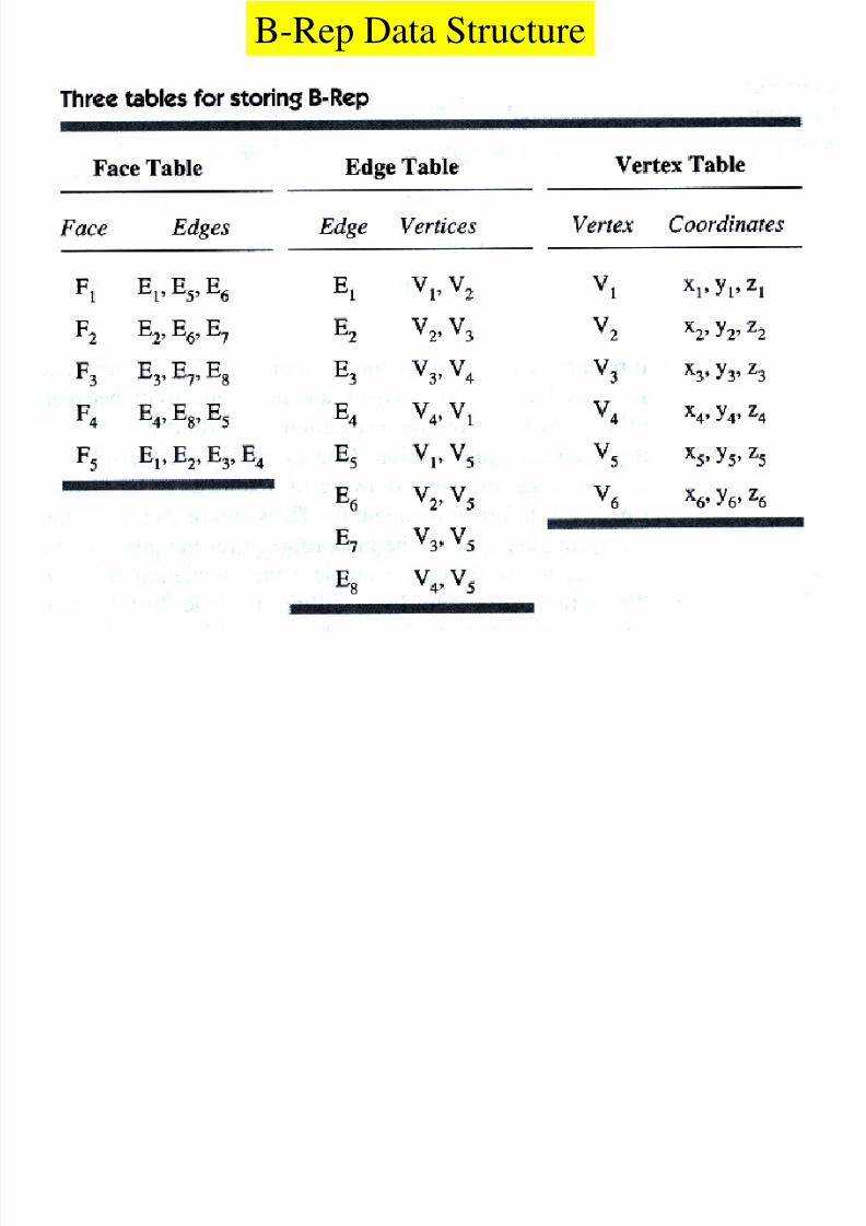
Boundary Representation
Objects are represented by their bounded faces.
8/3/2019 4 Modified)
http://slidepdf.com/reader/full/4-modified 23/26
B-Rep Data Structure

8/3/2019 4 Modified)
http://slidepdf.com/reader/full/4-modified 24/26

8/3/2019 4 Modified)
http://slidepdf.com/reader/full/4-modified 25/26

8/3/2019 4 Modified)
http://slidepdf.com/reader/full/4-modified 26/26