Embed Size (px)
Citation preview

Essex Electronics, Inc. | 805.684.7601 | 800.KEY-LESS | fax 805.684.0232 | keyless.com
○ ○ ○ ○ ○
INSTALLATION & INSTRUCTION MANUAL
K1 SeriesAll-In-One 12-Pad
Essex Electronics, Inc. | 805.684.7601 | 800.KEY-LESS | fax 805.684.0232 | keyless.comi
All rights reserved. No part of this documentation may be reproduced inany form, without prior written consent of Essex Electronics, Inc. EssexElectronics shall not be liable for errors contained in this manual. Theinformation in this document is subject to change without notice. EssexElectronics, Inc. reserves the right to modify this documentation and tomake improvements or changes to the product(s) contained in thisdocumentation at any time.
Document InformationIOMK1 Installation/Operations Manual for the K1 Series All-In-One 12-Pad3x4 and 2x6 - August 2007. This documentation is also applicable to priorrevisions except where noted.
Product InformationThis device complies with Part 15 of the FCC rules. Operation is subject tothe following two conditions: (1) This device may not cause harmfulinterference, and (2) this device must accept any interference includinginterference that may cause undesired operation.
TrademarksKeyless Entry® is a registered trademark of Essex Electronics, Inc.
Contact InformationEssex Electronics, Incorporated1130 Mark Avenue, Carpinteria, CA 93013(805) 684-7601 or (800) 539-5377 (KEY-LESS)FAX (805) 684-0232
Website: keyless.comGeneral email: [email protected] Support email: [email protected]
Copyright© 2005 Essex Electronics, Inc. All rights reserved.
K1 Series All-In-One 12-PadMulti-Format Keypad Reader
Essex Electronics, Inc. | 805.684.7601 | 800.KEY-LESS | fax 805.684.0232 | keyless.com ii
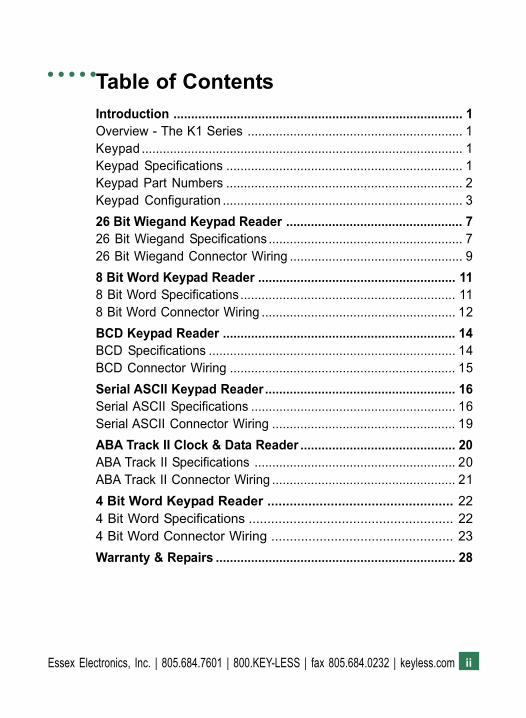
Introduction .................................................................................. 1Overview - The K1 Series ............................................................. 1Keypad ........................................................................................... 1Keypad Specifications ................................................................... 1Keypad Part Numbers ................................................................... 2Keypad Configuration .................................................................... 326 Bit Wiegand Keypad Reader .................................................. 726 Bit Wiegand Specifications ....................................................... 726 Bit Wiegand Connector Wiring ................................................. 98 Bit Word Keypad Reader ........................................................ 118 Bit Word Specifications............................................................. 118 Bit Word Connector Wiring ....................................................... 12BCD Keypad Reader .................................................................. 14BCD Specifications ...................................................................... 14BCD Connector Wiring ................................................................ 15Serial ASCII Keypad Reader...................................................... 16Serial ASCII Specifications .......................................................... 16Serial ASCII Connector Wiring .................................................... 19ABA Track II Clock & Data Reader ............................................ 20ABA Track II Specifications ......................................................... 20ABA Track II Connector Wiring .................................................... 214 Bit Word Keypad Reader .................................................. 224 Bit Word Specifications ....................................................... 224 Bit Word Connector Wiring ................................................. 23Warranty & Repairs .................................................................... 28
Table of Contents○ ○ ○ ○ ○

Essex Electronics, Inc. | 805.684.7601 | 800.KEY-LESS | fax 805.684.0232 | keyless.comiii
1Essex Electronics, Inc. | 805.684.7601 | 800.KEY-LESS | fax 805.684.0232 | keyless.com
Introduction!!!!! Overview � The K1 Series
○ ○ ○ ○
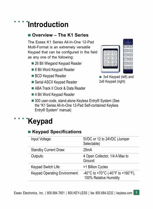
!!!!! 3x4 Keypad (left) and2x6 Keypad (right)
The Essex K1 Series All-In-One 12-PadMulti-Format is an extremely versatileKeypad that can be configured in the fieldas any one of the following:! 26 Bit Wiegand Keypad Reader! 8 Bit Word Keypad Reader! BCD Keypad Reader! Serial ASCII Keypad Reader! ABA Track II Clock & Data Reader! 4 Bit Word Keypad Reader! 500 user-code, stand-alone Keyless Entry® System (See
the �K1 Series All-In-One 12-Pad Self-contained KeylessEntry® System� manual)
Input Voltage: 5VDC or 12 to 24VDC (JumperSelectable)
Standby Current Draw: 25mAOutputs: 4 Open Collector, 1/4 A Max to
GroundKeypad Switch Life: >1 Billion CyclesKeypad Operating Environment: -40°C to +70°C (-40°F to +160°F),
100% Relative Humidity
Keypad!!!!! Keypad Specifications
○ ○ ○ ○

Essex Electronics, Inc. | 805.684.7601 | 800.KEY-LESS | fax 805.684.0232 | keyless.com2
Keypad!!!!! Keypad Specifications, cont�d.
○ ○ ○ ○
3x4 Keypad Dimensions: 5-1/8"H x 3-3/8"W x 7/16"D(13 x 8.6 x 1.1 cm)
2x6 Keypad Dimensions: 7-1/8"H x 1-3/4"W x 3/4"D (13 x 8.6 x 1.1 cm)
3x4 Keypad Weight: 16 oz (454 gm)2x6 Keypad Weight: 4.4 oz (125 gm)LED's: 1 Red, 1 Green
!!!!! Keypad Part Numbers
3x4 KeypadK1-34B Brass Finished* BezelK1-34S Stainless Steel BezelK1-34K Black BezelK1-34X No Bezel
2x6 KeypadK1-26B Brass OverlayK1-26I IlluminatedK1-26S Stainless Steel OverlayK1-26R Braille Overlay*Bezel is brass in appearance. Actual bezel is PVD-coated stainlesssteel.
3Essex Electronics, Inc. | 805.684.7601 | 800.KEY-LESS | fax 805.684.0232 | keyless.com
!!!!! Keypad Configuration
Voltage SelectionThe factory default setting for the Keypad voltage is 12-24VDC.Verify that the jumper is removed or placed over only one pin. For5VDC, the jumper should be placed across both pins. If changingthe voltage is necessary, make sure the power is removed first.
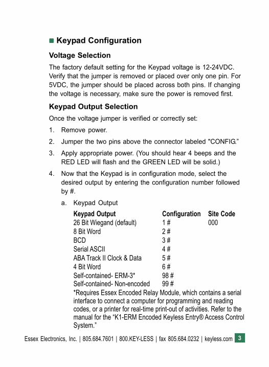
Keypad Output SelectionOnce the voltage jumper is verified or correctly set:
1. Remove power.
2. Jumper the two pins above the connector labeled "CONFIG.�
3. Apply appropriate power. (You should hear 4 beeps and theRED LED will flash and the GREEN LED will be solid.)
4. Now that the Keypad is in configuration mode, select thedesired output by entering the configuration number followedby #.
a. Keypad OutputKeypad Output Configuration Site Code26 Bit Wiegand (default) 1 # 0008 Bit Word 2 #BCD 3 #Serial ASCII 4 #ABA Track II Clock & Data 5 #4 Bit Word 6 #Self-contained- ERM-3* 98 #Self-contained- Non-encoded 99 #*Requires Essex Encoded Relay Module, which contains a serialinterface to connect a computer for programming and readingcodes, or a printer for real-time print-out of activities. Refer to themanual for the �K1-ERM Encoded Keyless Entry® Access ControlSystem.�
Essex Electronics, Inc. | 805.684.7601 | 800.KEY-LESS | fax 805.684.0232 | keyless.com4
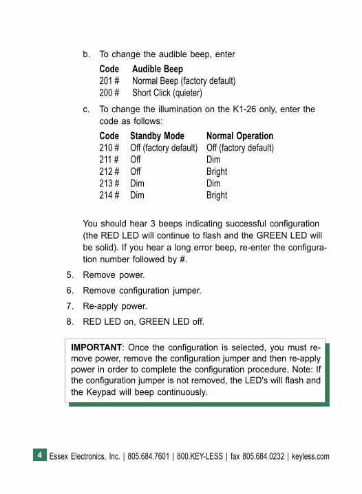
b. To change the audible beep, enterCode Audible Beep201 # Normal Beep (factory default)200 # Short Click (quieter)
c. To change the illumination on the K1-26 only, enter thecode as follows:Code Standby Mode Normal Operation210 # Off (factory default) Off (factory default)211 # Off Dim212 # Off Bright213 # Dim Dim214 # Dim Bright
You should hear 3 beeps indicating successful configuration(the RED LED will continue to flash and the GREEN LED willbe solid). If you hear a long error beep, re-enter the configura-tion number followed by #.
5. Remove power.
6. Remove configuration jumper.
7. Re-apply power.
8. RED LED on, GREEN LED off.
IMPORTANT: Once the configuration is selected, you must re-move power, remove the configuration jumper and then re-applypower in order to complete the configuration procedure. Note: Ifthe configuration jumper is not removed, the LED's will flash andthe Keypad will beep continuously.
5Essex Electronics, Inc. | 805.684.7601 | 800.KEY-LESS | fax 805.684.0232 | keyless.com
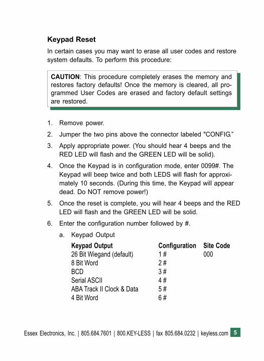
1. Remove power.
2. Jumper the two pins above the connector labeled "CONFIG.�
3. Apply appropriate power. (You should hear 4 beeps and theRED LED will flash and the GREEN LED will be solid).
4. Once the Keypad is in configuration mode, enter 0099#. TheKeypad will beep twice and both LEDS will flash for approxi-mately 10 seconds. (During this time, the Keypad will appeardead. Do NOT remove power!)
5. Once the reset is complete, you will hear 4 beeps and the REDLED will flash and the GREEN LED will be solid.
6. Enter the configuration number followed by #.
a. Keypad OutputKeypad Output Configuration Site Code26 Bit Wiegand (default) 1 # 0008 Bit Word 2 #BCD 3 #Serial ASCII 4 #ABA Track II Clock & Data 5 #4 Bit Word 6 #
Keypad ResetIn certain cases you may want to erase all user codes and restoresystem defaults. To perform this procedure:
CAUTION: This procedure completely erases the memory andrestores factory defaults! Once the memory is cleared, all pro-grammed User Codes are erased and factory default settingsare restored.
Essex Electronics, Inc. | 805.684.7601 | 800.KEY-LESS | fax 805.684.0232 | keyless.com6
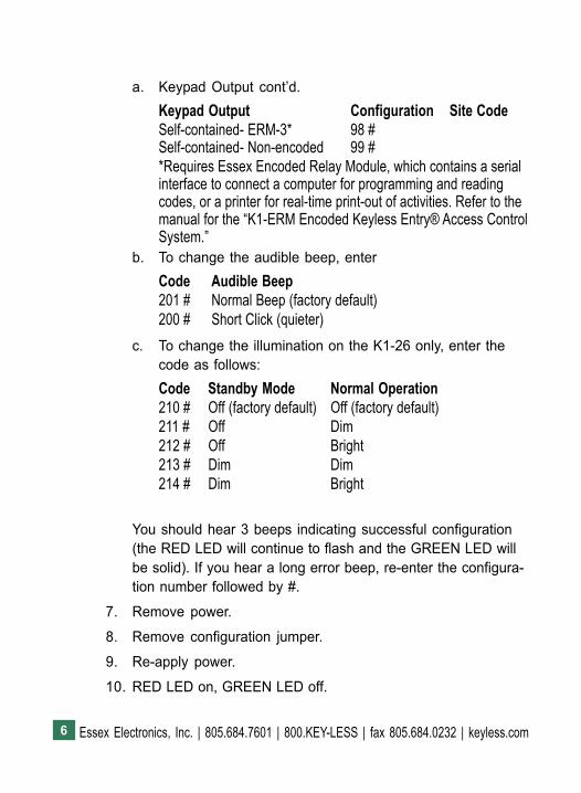
a. Keypad Output cont�d.Keypad Output Configuration Site CodeSelf-contained- ERM-3* 98 #Self-contained- Non-encoded 99 #*Requires Essex Encoded Relay Module, which contains a serialinterface to connect a computer for programming and readingcodes, or a printer for real-time print-out of activities. Refer to themanual for the �K1-ERM Encoded Keyless Entry® Access ControlSystem.�
b. To change the audible beep, enterCode Audible Beep201 # Normal Beep (factory default)200 # Short Click (quieter)
c. To change the illumination on the K1-26 only, enter thecode as follows:Code Standby Mode Normal Operation210 # Off (factory default) Off (factory default)211 # Off Dim212 # Off Bright213 # Dim Dim214 # Dim Bright
You should hear 3 beeps indicating successful configuration(the RED LED will continue to flash and the GREEN LED willbe solid). If you hear a long error beep, re-enter the configura-tion number followed by #.
7. Remove power.
8. Remove configuration jumper.
9. Re-apply power.
10. RED LED on, GREEN LED off.
7Essex Electronics, Inc. | 805.684.7601 | 800.KEY-LESS | fax 805.684.0232 | keyless.com
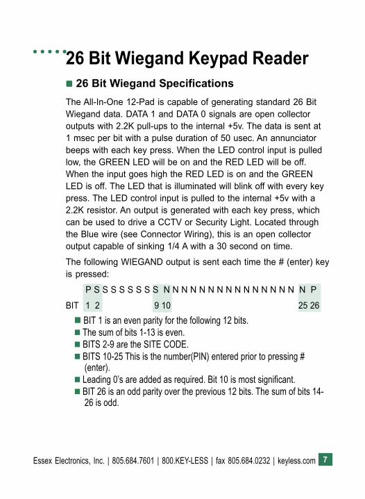
26 Bit Wiegand Keypad Reader!!!!! 26 Bit Wiegand SpecificationsThe All-In-One 12-Pad is capable of generating standard 26 BitWiegand data. DATA 1 and DATA 0 signals are open collectoroutputs with 2.2K pull-ups to the internal +5v. The data is sent at1 msec per bit with a pulse duration of 50 usec. An annunciatorbeeps with each key press. When the LED control input is pulledlow, the GREEN LED will be on and the RED LED will be off.When the input goes high the RED LED is on and the GREENLED is off. The LED that is illuminated will blink off with every keypress. The LED control input is pulled to the internal +5v with a2.2K resistor. An output is generated with each key press, whichcan be used to drive a CCTV or Security Light. Located throughthe Blue wire (see Connector Wiring), this is an open collectoroutput capable of sinking 1/4 A with a 30 second on time.
The following WIEGAND output is sent each time the # (enter) keyis pressed:
P S S S S S S S S N N N N N N N N N N N N N N N N P
BIT 1 2 9 10 25 26! BIT 1 is an even parity for the following 12 bits.! The sum of bits 1-13 is even.! BITS 2-9 are the SITE CODE.! BITS 10-25 This is the number(PIN) entered prior to pressing #
(enter).! Leading 0�s are added as required. Bit 10 is most significant.! BIT 26 is an odd parity over the previous 12 bits. The sum of bits 14-
26 is odd.
○ ○ ○ ○ ○
Essex Electronics, Inc. | 805.684.7601 | 800.KEY-LESS | fax 805.684.0232 | keyless.com8
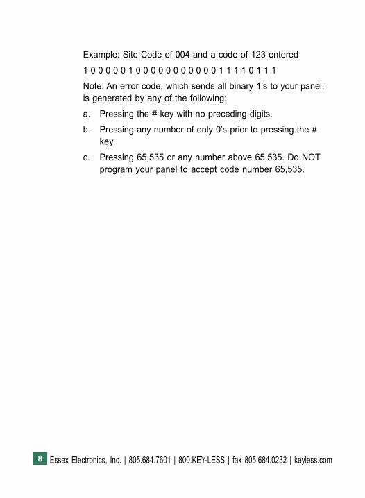
Example: Site Code of 004 and a code of 123 entered
1 0 0 0 0 0 1 0 0 0 0 0 0 0 0 0 0 0 1 1 1 1 0 1 1 1
Note: An error code, which sends all binary 1�s to your panel,is generated by any of the following:
a. Pressing the # key with no preceding digits.
b. Pressing any number of only 0�s prior to pressing the #key.
c. Pressing 65,535 or any number above 65,535. Do NOTprogram your panel to accept code number 65,535.
9Essex Electronics, Inc. | 805.684.7601 | 800.KEY-LESS | fax 805.684.0232 | keyless.com
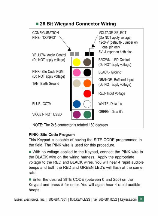
PINK- Site Code ProgramThis Keypad is capable of having the SITE CODE programmed inthe field. The PINK wire is used for this procedure.
! With no voltage applied to the Keypad, connect the PINK wire tothe BLACK wire on the wiring harness. Apply the appropriatevoltage to the RED and BLACK wires. You will hear 4 rapid audiblebeeps and both the RED and GREEN LED�s will flash at the samerate.
! Enter the desired SITE CODE (between 0 and 255) on theKeypad and press # for enter. You will again hear 4 rapid audiblebeeps.
CONFIGURATIONPINS- �CONFIG�
VOLTAGE SELECT(Do NOT apply voltage)12-24V (default)- Jumper on
one pin only5V- Jumper on both pins
YELLOW- Audio Control(Do NOT apply voltage)
PINK- Site Code PGM(Do NOT apply voltage)
BLUE- CCTV
BROWN- LED Control(Do NOT apply voltage)
TAN- Earth Ground
BLACK- Ground
ORANGE- Buffered Input(Do NOT apply voltage)
VIOLET- NOT USED
RED- Input Voltage
WHITE- Data 1�s
GREEN- Data 0�s
!!!!! 26 Bit Wiegand Connector Wiring
NOTE: The 2x6 connector is rotated 180 degrees
Essex Electronics, Inc. | 805.684.7601 | 800.KEY-LESS | fax 805.684.0232 | keyless.com10
! At this point the Keypad will appear non-functional and will notaccept any entries. (If the wrong key is pressed during the pro-gramming sequence, pressing the * key will clear the entry. Youwill then hear 2 rapid beeps and both LED�s will flash at the samerate. The Keypad will generate an error tone if you enter a SITECODE over 255.)
! Disconnect power to the RED wire and disconnect the PINK wirefrom the BLACK wire.
Now you can connect the standard Wiegand 5 wires to the Keypadand the programmed SITE CODE will be generated as part of the26 Bit data when the enter key (#) is pressed.
This procedure may be repeated to change the SITE CODE.
The factory default site code is 000.
BLUE- CCTVPressing any position on the Keypad will generate a 30-second,0.25 Amp, intermittent duty grounding output on the BLUE wire.
ORANGE- Buffered/Hold LineWhen the Hold Line or ORANGE wire is pulled low, codes enteredon the Keypad are stored in the buffer. When the Hold Line isreleased to a logic high, the buffered code is sent. This input ispulled high with a 2.2K resistor.
YELLOW- Audio ControlPulling YELLOW low (grounding) causes the beeper to sound.
TAN- Case GroundIn higher static prone areas, the TAN wire is used to divert staticdischarge away from the microprocessor in the Keypad. Ideally,the TAN wire should be connected to a known Earth Ground at theKeypad installation point (Do NOT run back to the panel throughthe cable).
11Essex Electronics, Inc. | 805.684.7601 | 800.KEY-LESS | fax 805.684.0232 | keyless.com
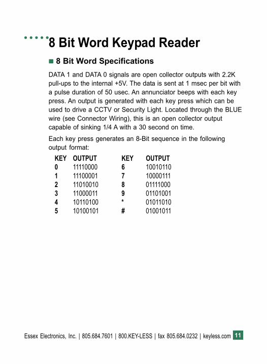
8 Bit Word Keypad Reader!!!!! 8 Bit Word SpecificationsDATA 1 and DATA 0 signals are open collector outputs with 2.2Kpull-ups to the internal +5V. The data is sent at 1 msec per bit witha pulse duration of 50 usec. An annunciator beeps with each keypress. An output is generated with each key press which can beused to drive a CCTV or Security Light. Located through the BLUEwire (see Connector Wiring), this is an open collector outputcapable of sinking 1/4 A with a 30 second on time.
Each key press generates an 8-Bit sequence in the followingoutput format:
KEY OUTPUT KEY OUTPUT0 11110000 6 100101101 11100001 7 100001112 11010010 8 011110003 11000011 9 011010014 10110100 * 010110105 10100101 # 01001011
○ ○ ○ ○ ○
Essex Electronics, Inc. | 805.684.7601 | 800.KEY-LESS | fax 805.684.0232 | keyless.com12
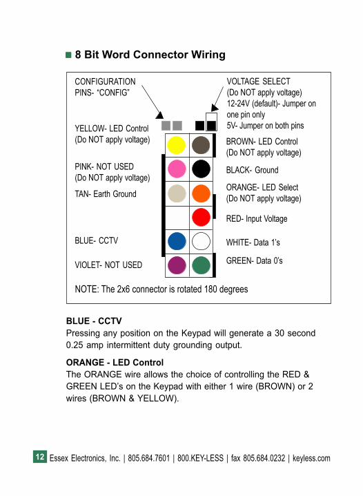
!!!!! 8 Bit Word Connector Wiring
BLUE - CCTVPressing any position on the Keypad will generate a 30 second0.25 amp intermittent duty grounding output.
ORANGE - LED ControlThe ORANGE wire allows the choice of controlling the RED &GREEN LED�s on the Keypad with either 1 wire (BROWN) or 2wires (BROWN & YELLOW).
CONFIGURATIONPINS- �CONFIG�
VOLTAGE SELECT(Do NOT apply voltage)12-24V (default)- Jumper onone pin only5V- Jumper on both pinsYELLOW- LED Control
(Do NOT apply voltage)
PINK- NOT USED(Do NOT apply voltage)
BLUE- CCTV
BROWN- LED Control(Do NOT apply voltage)
TAN- Earth Ground
BLACK- Ground
ORANGE- LED Select(Do NOT apply voltage)
VIOLET- NOT USED
RED- Input Voltage
WHITE- Data 1�s
GREEN- Data 0�s
NOTE: The 2x6 connector is rotated 180 degrees
13Essex Electronics, Inc. | 805.684.7601 | 800.KEY-LESS | fax 805.684.0232 | keyless.com
ORANGE - LED Control, cont�d.a. When the ORANGE wire is floating (not connected), two wires
control the LED�s. When the BROWN wire is pulled low(grounded), the GREEN LED is on. When the YELLOW wire ispulled low, the RED LED is on.
b. To control both LED�s with one wire (BROWN), pull theORANGE wire low. When the LED control input is pulled low,the GREEN LED will be on and the RED LED will be off. Whenthe input goes high, the RED LED will be on and the GREENLED will be off. The LED that is illuminated will blink with everykey press. The LED control is pulled to the internal +5 with a2.2K resistor.
Essex Electronics, Inc. | 805.684.7601 | 800.KEY-LESS | fax 805.684.0232 | keyless.com14
BCD Keypad Reader!!!!! BCD SpecificationsAn Output is generated with each key press with a pulse durationof 75 msec. If a longer pulse width is required, grounding the PINKwire on the connector will increase the pulse width to 150 msec.An annunciator beeps with each key press.
The output is BCD SINKING with internal 2.2K ohm pull-upresistors. If a BCD SOURCING output is required, grounding theORANGE wire on the connector will convert the output to BCDSOURCING thru 2.2K ohm resistors. The resistors are pulled upto the internal 5V.
The BCD outputs are:
1 GREEN2 WHITE4 VIOLET8 BLUE
! Position �0� is sent as a 10
! Position �*� is sent as an 11
! Position �#� is sent as a 12
○ ○ ○ ○ ○
15Essex Electronics, Inc. | 805.684.7601 | 800.KEY-LESS | fax 805.684.0232 | keyless.com
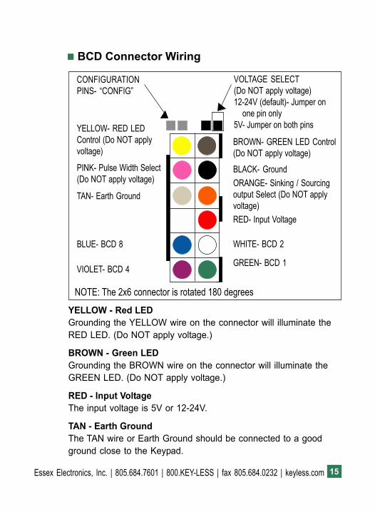
!!!!! BCD Connector Wiring
YELLOW - Red LEDGrounding the YELLOW wire on the connector will illuminate theRED LED. (Do NOT apply voltage.)
BROWN - Green LEDGrounding the BROWN wire on the connector will illuminate theGREEN LED. (Do NOT apply voltage.)
RED - Input VoltageThe input voltage is 5V or 12-24V.
TAN - Earth GroundThe TAN wire or Earth Ground should be connected to a goodground close to the Keypad.
CONFIGURATIONPINS- �CONFIG�
VOLTAGE SELECT(Do NOT apply voltage)12-24V (default)- Jumper on
one pin only5V- Jumper on both pinsYELLOW- RED LED
Control (Do NOT applyvoltage)
PINK- Pulse Width Select(Do NOT apply voltage)
BLUE- BCD 8
BROWN- GREEN LED Control(Do NOT apply voltage)
TAN- Earth Ground
BLACK- GroundORANGE- Sinking / Sourcingoutput Select (Do NOT applyvoltage)
VIOLET- BCD 4
RED- Input Voltage
WHITE- BCD 2
GREEN- BCD 1
NOTE: The 2x6 connector is rotated 180 degrees
Essex Electronics, Inc. | 805.684.7601 | 800.KEY-LESS | fax 805.684.0232 | keyless.com16
Serial ASCII Keypad Reader!!!!! Serial ASCII SpecificationsNormal Serial and Inverted Serial signals are open collectoroutputs with 2.2K pull-ups to the internal +5v. An annunciatorbeeps with each key press. When the LED control input is pulledlow, the GREEN LED will be on and the RED LED will be off.When the input goes high, the RED LED is on and the GREENLED is off. The RED LED will blink with every key press. The LEDcontrol input is pulled to the internal +5v with a 2.2K resistor. Anoutput is generated with each key press which can be used todrive a CCTV or Security Light. Available through the BLUE wire(see Connector Wiring), this is an open collector output capable ofsinking 1/4 A with a 30 second on time. The PINK wire is used tomodify the Keypad baud rate, parity and mode. This can beaccomplished in the field.
Modifying the Baud Rate, Parity and Mode1. Baud Rate (first digit)
With no voltage applied to the Keypad, connect the PINK wireto the BLACK wire on the wiring harness. Apply the appropri-ate voltage to the RED and BLACK wires. You will hear 4 rapidaudible beeps and both the RED and GREEN LED�s will flashat the same rate. Enter the desired first digit on the Keypad toselect the baud rate:
1 = 300 5 = 48002 = 600 6 = 96003 = 1200 7 = 192004 = 2400 8 = 38400Note: All baud rates have a timing error of < 0.2% + Xtal FreqError.
○ ○ ○ ○ ○
17Essex Electronics, Inc. | 805.684.7601 | 800.KEY-LESS | fax 805.684.0232 | keyless.com
If the wrong baud rate is selected, pressing the * key beforeentering the parity option will clear the entry. The Keypad willgenerate an error tone if you enter an invalid number. Youshould hear 2 audible beeps and the RED LED will continueblinking fast while the GREEN LED will blink slow.
2. Parity Option (second digit)
Next, enter the desired second digit on the Keypad to selectthe parity option:
0 = None (8 Data Bits)1 = Odd (7 Data Bits + Odd Parity Bit)2 = Even (7 Data Bits + Even Parity Bit)Note: All Parity formats have a single Start and Stop Bit.
If the wrong parity is selected, pressing the * key beforeentering the mode option will clear the entry. The Keypad willgenerate an error tone if you enter an invalid number. Youshould hear 2 audible beeps and the RED LED will continueblinking fast while the GREEN LED will be solid.
3. Mode (third digit)
To select the desired mode option, enter the desired third digiton the Keypad:
0 = NORMAL (Single character output with each keystroke)*Sends ASCII* - #Sends ASCII#1 = ALTCHAR (Single character output with each keystroke)*Sends ASCII <ESC> - # Sends ASCII <CR>2 = BUFFERBUFFER mode accepts up to 10 characters. If more than 10 charac-ters are entered, you will hear an error beep and the buffer will becleared. Pressing # sends buffered characters + ASCII <CR> at end.Pressing * clears the buffer and outputs 2 beeps. Clear buffer timeoutset to 10 seconds.
Essex Electronics, Inc. | 805.684.7601 | 800.KEY-LESS | fax 805.684.0232 | keyless.com18
You should hear 3 rapid audible beeps and see both LED�sextinguish. At this point the Keypad will appear dead and notaccept any entries.
Examples:
3 1 0 (Sets 1200 baud, odd pariety and normal mode)7 0 2 (Sets 19200 baud, no pariety and buffered mode)This procedure may be repeated to change the Baud Rate andParity option. You must enter all three digits even if you wish tochange only one setting. Factory default is 9600 baud, no parity,normal.
Disconnect power to the RED wire and disconnect the PINK wirefrom the BLACK wire.
NORMAL mode outputs the following codes:0 - 0x30 6 - 0x361 - 0x31 7 - 0x372 - 0x32 8 - 0x383 - 0x33 9 - 0x394 - 0x34 * - 0x2A5 - 0x35 # - 0x23ALTCHAR mode outputs the following codes:0 - 0x30 6 - 0x361 - 0x31 7 - 0x372 - 0x32 8 - 0x383 - 0x33 9 - 0x394 - 0x34 * - 0x1B5 - 0x35 # - 0x0D
Note: All serial output formats use a single start and stop bit.
19Essex Electronics, Inc. | 805.684.7601 | 800.KEY-LESS | fax 805.684.0232 | keyless.com
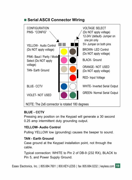
!!!!! Serial ASCII Connector Wiring
BLUE - CCTVPressing any position on the Keypad will generate a 30 second0.25 amp intermittent duty grounding output.
YELLOW- Audio ControlPulling YELLOW low (grounding) causes the beeper to sound.
TAN - Earth GroundCase ground at the Keypad installation point, not through thecable.
Typical connection: WHITE to Pin 2 of DB-9 (232 RX), BLACK toPin 5, and Power Supply Ground.
CONFIGURATIONPINS- �CONFIG�
VOLTAGE SELECT(Do NOT apply voltage)12-24V (default)- Jumper on
one pin only5V- Jumper on both pinsYELLOW- Audio Control
(Do NOT apply voltage)
PINK- Baud / Parity / ModeSelect (Do NOT applyvoltage)
BLUE- CCTV
BROWN- LED Control(Do NOT apply voltage)
TAN- Earth Ground
BLACK- Ground
ORANGE- NOT USED(Do NOT apply voltage)
VIOLET- NOT USED
RED- Input Voltage
WHITE- Inverted Serial Output
GREEN- Normal Serial Output
NOTE: The 2x6 connector is rotated 180 degrees
Essex Electronics, Inc. | 805.684.7601 | 800.KEY-LESS | fax 805.684.0232 | keyless.com20
ABA Track II Clock & Data Reader!!!!! ABA Track II SpecificationsGREEN <Clock> goes low to clock in data. WHITE <Data> outputis determined by ORANGE. If ORANGE is low, then Data output isinverted. If ORANGE is high, then Data output is normal.
Clock and Data signals are open collector outputs with 2.2K pull-ups to the internal +5v. Clock Pulse is sent at 200 usec. Interbitdelay is 750 usec. An annunciator beeps with each key press. Anoutput is generated with each key press which can be used todrive a CCTV or Security Light. Located through the BLUE wire(see Connector Wiring), this is an open collector output capable ofsinking 1/4 A with a 30 second on time.
Each key press generates an ABA Data Format as follows:
1. Each character is sent as a 5 bit value. The first 4 bits of eachcharacter are the data value LSB first. The last bit of eachcharacter is an odd parity bit. The first four 0�s are sent as leadin.
2. The Start Character is sent next. The Start Character is a �B�with odd parity bit. Each entered character is now sent as 5bits per character with odd parity and LSB first. There can beup to a max of 12 characters.
3. After all the keyed in characters have been sent, then the EndSentinel is sent. The End Sentinel is an �F� with odd parity.Next the LRC code is sent as a 5 bit character with odd parity.The LRC code is created by XORing all of the characters sentincluding the Start Characters, the Digit Characters and theEnd Sentinel. It is calculated as a 4 bit value from XORing allthe previous characters. Its value is then sent as a 5 bit value,the 5th bit being its own odd parity.
○ ○ ○ ○ ○
21Essex Electronics, Inc. | 805.684.7601 | 800.KEY-LESS | fax 805.684.0232 | keyless.com
4. Finally 7 0 bits are sent as lead out.
Notes:! # is the Enter key and * is the Clear key. If # is pressed with no datakey first, there is no output from the keypad.! If over 12 data keys are pressed before enter, there is no output from thekeypad.
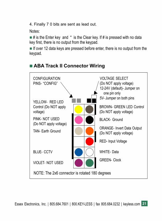
!!!!! ABA Track II Connector Wiring
CONFIGURATIONPINS- �CONFIG�
VOLTAGE SELECT(Do NOT apply voltage)12-24V (default)- Jumper on
one pin only5V- Jumper on both pins
YELLOW- RED LEDControl (Do NOT applyvoltage)PINK- NOT USED(Do NOT apply voltage)
BLUE- CCTV
BROWN- GREEN LED Control(Do NOT apply voltage)
TAN- Earth Ground
BLACK- Ground
ORANGE- Invert Data Output(Do NOT apply voltage)
VIOLET- NOT USED
RED- Input Voltage
WHITE- Data
GREEN- Clock
NOTE: The 2x6 connector is rotated 180 degrees
Essex Electronics, Inc. | 805.684.7601 | 800.KEY-LESS | fax 805.684.0232 | keyless.com22
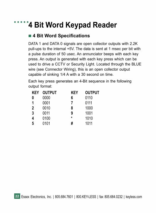
4 Bit Word Keypad Reader!!!!! 4 Bit Word SpecificationsDATA 1 and DATA 0 signals are open collector outputs with 2.2Kpull-ups to the internal +5V. The data is sent at 1 msec per bit witha pulse duration of 50 usec. An annunciator beeps with each keypress. An output is generated with each key press which can beused to drive a CCTV or Security Light. Located through the BLUEwire (see Connector Wiring), this is an open collector outputcapable of sinking 1/4 A with a 30 second on time.
Each key press generates an 4-Bit sequence in the followingoutput format:
KEY OUTPUT KEY OUTPUT0 0000 6 01101 0001 7 01112 0010 8 10003 0011 9 10014 0100 * 10105 0101 # 1011
○ ○ ○ ○ ○
23Essex Electronics, Inc. | 805.684.7601 | 800.KEY-LESS | fax 805.684.0232 | keyless.com
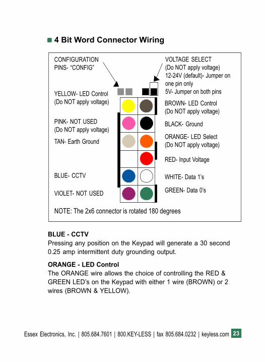
!!!!! 4 Bit Word Connector Wiring
BLUE - CCTVPressing any position on the Keypad will generate a 30 second0.25 amp intermittent duty grounding output.
ORANGE - LED ControlThe ORANGE wire allows the choice of controlling the RED &GREEN LED�s on the Keypad with either 1 wire (BROWN) or 2wires (BROWN & YELLOW).
CONFIGURATIONPINS- �CONFIG�
VOLTAGE SELECT(Do NOT apply voltage)12-24V (default)- Jumper onone pin only5V- Jumper on both pinsYELLOW- LED Control
(Do NOT apply voltage)
PINK- NOT USED(Do NOT apply voltage)
BLUE- CCTV
BROWN- LED Control(Do NOT apply voltage)
TAN- Earth Ground
BLACK- Ground
ORANGE- LED Select(Do NOT apply voltage)
VIOLET- NOT USED
RED- Input Voltage
WHITE- Data 1�s
GREEN- Data 0�s
NOTE: The 2x6 connector is rotated 180 degrees

Essex Electronics, Inc. | 805.684.7601 | 800.KEY-LESS | fax 805.684.0232 | keyless.com24
ORANGE - LED Control, cont�d.a. When the ORANGE wire is floating (not connected), two wires
control the LED�s. When the BROWN wire is pulled low(grounded), the GREEN LED is on. When the YELLOW wire ispulled low, the RED LED is on.
b. To control both LED�s with one wire (BROWN), pull theORANGE wire low. When the LED control input is pulled low,the GREEN LED will be on and the RED LED will be off. Whenthe input goes high, the RED LED will be on and the GREENLED will be off. The LED that is illuminated will blink with everykey press. The LED control is pulled to the internal +5 with a2.2K resistor.

25Essex Electronics, Inc. | 805.684.7601 | 800.KEY-LESS | fax 805.684.0232 | keyless.com
Notes○ ○ ○ ○ ○

Essex Electronics, Inc. | 805.684.7601 | 800.KEY-LESS | fax 805.684.0232 | keyless.com26
Notes○ ○ ○ ○ ○

27Essex Electronics, Inc. | 805.684.7601 | 800.KEY-LESS | fax 805.684.0232 | keyless.com
Notes○ ○ ○ ○ ○

Essex Electronics, Inc. | 805.684.7601 | 800.KEY-LESS | fax 805.684.0232 | keyless.com28
Warranty & Repairs!!!!! Limited Lifetime Warranty
(effective date May 1, 2006)
Essex Electronics Inc. warrants that at the time of originalpurchase from Essex Electronics Inc., the products specified beloware free from defects in workmanship and material. Subject to theconditions and limitations set forth below, Essex Electronics Inc.will, at its option, either repair or replace any part of its productsthat prove defective by reason of improper workmanship ormaterials. Repaired parts or replacement products will be providedby Essex Electronics Inc. on an exchange basis, and will be eithernew or refurbished to be functionally equivalent to new. EssexElectronics Inc. reserves the right to discontinue a product for anyreason, without notice, at any time. If a product that has beendiscontinued proves defective and if Essex Electronics Inc. isunable to repair or replace the product, within the terms expressedin this Limited Lifetime Warranty, a substitute product may beprovided at the Essex Electronics Inc.�s election, as a replacementfor the original discontinued product.
This Limited Lifetime Warranty extends only to the original retail orwholesale Buyer and the original site of installation. It does notcover any damage to this product or parts thereof, if the product isinstalled in violation of the applicable codes or ordinances, or isnot installed in accordance with our installation instructions. Thiswarranty will only include the normal operating life of the LED�swhich will be 10 years from the date of the original sale. It does notcover any damage that results from accident, abuse, misuse,natural disaster, insufficient or excessive electrical supply, abnor-mal mechanical or environmental conditions, or any unauthorizeddisassembly, repair, or modification. This Limited Lifetime Warranty
○ ○ ○ ○ ○

29Essex Electronics, Inc. | 805.684.7601 | 800.KEY-LESS | fax 805.684.0232 | keyless.com
also does not apply to any product on which the original identifica-tion or date of manufacture information has been altered, obliter-ated or removed. In no event shall Essex Electronics Inc. be liablefor any damage to persons, property or area surrounding theinstallation site caused by any malfunction of the product manufac-tured by Essex Electronics Inc.
Essex Electronics Inc. will not pay, nor be responsible for, shipping,transportation or delivery charges, or other cost of removal of adefective product or installation of a replacement product. Theoriginal component replaced under this Limited Lifetime Warrantyin any system shall become the property of Essex Electronics Inc.,and as such will, at our request, be returned to our factory withtransportation charges paid by the Buyer.
Limited Lifetime WarrantyThe Essex Electronics Inc. products with a manufactured date of 5/1/06 to the present date that are covered by this Limited LifetimeWarranty are Keypads, Keyless Entry Access Control Systems andaccessories.
Essex Electronics, Inc.�s liability and Buyer�s remedy under thiswarranty is limited to the repair or replacement at Seller�s electionof the product, or parts thereof, returned to Essex Electronics Inc.at Buyer�s expense and shown to Essex Electronics Inc.�s reason-able satisfaction to have been defective.
Notice of any defect must be sent to Essex Electronics, Inc., 1130Mark Avenue, Carpinteria, California, 93013, USA and mustinclude the date code of the unit, description of the defect andfactory assigned Return Authorization #. Upon receipt of suchnotification, Essex will determine whether to repair or replace. Wealso reserve the right to have our representative make any inspec-tion or repairs, or furnish replacements.
Essex Electronics, Inc. | 805.684.7601 | 800.KEY-LESS | fax 805.684.0232 | keyless.com30
This warranty excludes Elevator and Vehicle Keyless Entry AccessControl Systems. A separate warranty applies to Keyless Entrysystems manufactured for these applications.
Disclaimer of Warranties: Limitation of Buyer�s RemediesExcept for the repair or replacement at seller�s option which isexpressly set forth above, Essex Electronics Inc. extends nowarranty of any kind, express or implied, and disclaims any impliedwarranty of merchantability or suitability for purpose for which sold,with respect to the keypads, keyless entry coded access system oraccessories. Except for the limited repair or replacement specifiedabove, under no circumstances will Essex Electronics Inc. beliable to buyer under or in connection with any manufacture or saleof any of the products set forth above under any tort, negligence,strict liability, contract or other legal or equitable theory, or forincidental or consequential damages, or buyer�s cost of effectinginsurance coverage.
The foregoing limited lifetime warranty expressed herein consti-tutes the sole and entire warranty with respect to the products setforth above and is in place of any and all other warranties, expressor implied.
This warranty may not be expanded or extended by any oralrepresentation, written sales information, advertising, drawings orotherwise. Essex Electronics Inc. is not responsible hereunder forincidental damage to person or property, or other incidental orconsequential damages. The remedies of the buyer shall belimited to those provided in this limited lifetime warranty to theexclusion of any and all other remedies, including, without limita-tion, incidental or consequential damages.
This Limited Lifetime Warranty shall be governed by and inter-preted in accordance with the California Uniform CommercialCode and by the procedural laws of the State of California. Any

31Essex Electronics, Inc. | 805.684.7601 | 800.KEY-LESS | fax 805.684.0232 | keyless.com
lawsuit or other action which arises out of, relates to, or is inconnection with the manufacture or sale of the products set forthabove shall be governed by California law, and the venue for anysuch action shall be the Superior Court of the State of California inand for Santa Barbara County, California.
!!!!! Repair PolicyShould it be necessary for a component or a system to be re-turned for repair, it must be accompanied with an RA# (ReturnAuthorization Number) issued by the factory. Please call 1-800-KEYLESS (800-539-5377) to obtain an RA#. All returns must besent to the factory freight prepaid. Collect shipments will not beaccepted at any time. Standard turnaround time is ten (10) workingdays from the date of receipt. Repaired components will bereturned UPS Ground (or equivalent). Any other shipping requestsor instructions will be at the customer�s expense.
At the factory�s discretion, warranty repairs will include repair orreplacement, update and testing. Returns and repairs out of thewarranty period or in warranty with damage not covered underwarranty shall be subject to a repair charge. All non-warrantyrepair freight charges are paid for by the customer. Non-warrantyrepair charges are returned COD. (Factory Authorized Distributorsare subject to standard terms).

Essex Electronics, Inc. | 805.684.7601 | 800.KEY-LESS | fax 805.684.0232 | keyless.com
○ ○ ○ ○ ○

![arXiv:1608.00292v4 [math.GN] 12 Oct 2016 · 2016-10-13 · We show that the answer is no, ... i2!Ki.! K1 K2 K3 K0 K1 K2 K3 K0! K1 K2 K3 K0 K1 K2 K3 K0 Figure 2. K! K1 K2 K3 K0 K1](https://img.pdfslide.us/doc/110x75/5e779fd8cdc8f45d52235a34/arxiv160800292v4-mathgn-12-oct-2016-2016-10-13-we-show-that-the-answer-is.jpg)