Embed Size (px)
Citation preview

4-1 CivilFEM Workbook. Ingeciber, S.A.©
Ver. 14.5
4. Frame Reinforcement by Eurocode 2
Applicable CivilFEM Product: All CivilFEM Products
Level of Difficulty: Moderate
Interactive Time Required: 35 minutes
Discipline: Structural Concrete
Analysis Type: Linear static
Element Type Used: BEAM3
Active Code Eurocode 2
Units System N, m, s.
CivilFEM Features Demonstrated: Units selection, code selection, material definition, section definition by dimensions, axial and bending reinforcement checking, shear reinforcement checking, axial and bending reinforcement design, shear reinforcement design.
Problem Description
This example illustrates the Eurocode 2 designing criteria for a typical concrete constrained frame. We will use the program skills to check the frame reinforcement and to design the appropriate one if necessary. We will check for axial force, bending moment Z and shear in the Y direction.
We are not considering the self-weight of the reinforced frame. Nevertheless we will apply a distributed load along the left column.
D
B
MC
Y
Z
W
L
H
L

4-2 CivilFEM Workbook. Ingeciber, S.A.©
Ver. 14.5
Loads:
W = 40 kN/m
L = 60 kN/m
Frame geometrical dimensions:
Length L = 6 m
Height H = 5 m
Section properties:
Dimensions:
Width B = 0.4 m
Depth D = 0.5 m
Material:
Concrete C40/50
Steel S400 c=1.5 s=1.15
Reinforcement:
Bending reinforcement: Group 1 3 16 mm at face number 2 (Scalable)
Bending reinforcement: Group 2 3 16 mm at face number 4 (Scalable)
Shear reinforcement: 10 mm / 30 cm
Given
The load distribution, the section geometrical dimensions, material properties and safety factors for concrete and steel reinforcement are shown in the previous table.
Approach and Assumptions
We will use 2D elastic beam elements for this analysis. Model geometry will be defined by direct generation of nodes and elements.

4-3 CivilFEM Workbook. Ingeciber, S.A.©
Ver. 14.5
Summary of Steps
Preprocessing
1. Specify title
2. Set units
3. Set code
4. Define material
5. Define element type
6. Define section
7. Define bending reinforcement properties
8. Define shear reinforcement properties
9. Define Beam & Shell properties
10. Define nodes and elements
11. Save the database
Solution
12. Apply displacement constraints
13. Apply load
14. Solve
Postprocessing
15. Enter the postprocessor and read in results
16. Checking under 2D bending moment and axial force
17. Review elements OK and No OK
18. Plot an interaction diagram
19. Checking under shear force in Y axis
20. Review elements OK and No OK
21. Design for bending moment and axial force
22. Review designed reinforcement for bending moment and axial force
23. Design for shear force in Y axis
24. Review designed reinforcement for shear force
25. Exit the ANSYS program

4-4 CivilFEM Workbook. Ingeciber, S.A.©
Ver. 14.5
Interactive Step-by-Step Solution
Preprocessing
1. Specify title
Utility Menu: File Change title
Enter the title: “Frame Reinforcement by Eurocode 2”
OK to define the title and close the dialog box.
2. Set units
Utility Menu: CivilFEM Civil Setup
OK to accept meters, seconds and newtons and close the units dialog box
1
2
1
1
1
2

4-5 CivilFEM Workbook. Ingeciber, S.A.©
Ver. 14.5
3. Set code
Main Menu: CivilFEM Civil Setup
Pick on the Codes tab
OK to set active code and close the code dialog box.
4. Define material
Main Menu: – CivilFEM Civil Preprocess Materials
Choose New
Select concrete material type
Choose EC2: C40/50 concrete
Add to define material 1
Select Reinforcing steel material type
Choose EC2: S400 reinforcing steel
Add to define material 2 and Exit.
Ok to define material properties and close the dialog box
2
1
3
4
1
1
2
5
6
7
8

4-6 CivilFEM Workbook. Ingeciber, S.A.©
Ver. 14.5
1
2
3
4

4-7 CivilFEM Workbook. Ingeciber, S.A.©
Ver. 14.5
5
6
7
8

4-8 CivilFEM Workbook. Ingeciber, S.A.©
Ver. 14.5
5. Define element type
We will make use of BEAM3.
Main Menu: CivilFEM – Civil Preprocess Element Types Civil Beams
Select 2D Elastic Beam 3
OK to define element type
6. Define section
First, we will define the section geometry and then we will introduce the reinforcements.
Main Menu: CivilFEM Civil Preprocess Cross Sections
Pick on the Concrete button to define a concrete section
1
2
1
1
2

4-9 CivilFEM Workbook. Ingeciber, S.A.©
Ver. 14.5
Choose rectangular shape
Enter 0.5 as depth (TKY)
Enter 0.4 as width (TKZ)
Enter Rectangular Section as Name
To draw the rectangular section click with the right button on the window
Ok to define Concrete Section
Exit to close dialog box
7
2
3
5
6
4
1
8

4-10 CivilFEM Workbook. Ingeciber, S.A.©
Ver. 14.5
7 5
3
4
2
8
6

4-11 CivilFEM Workbook. Ingeciber, S.A.©
Ver. 14.5
7. Define bending reinforcement properties
To define the bending reinforcement we have to take into account the following facts:
a) Number of reinforcement groups to be defined. b) Material of reinforcement group. c) Class of reinforcement group. d) Amount of reinforcement per group. e) Location of reinforcement group.
We will define two reinforcement groups as it was indicated in the section’s graph.
The characteristics of the reinforcement of group 1 are shown in the following table:
Group 1 Reinforcement material Material 2 (S 400) Reinforcement class Scalable
Diameter 16 mm
Number of bars 3
Face number 2
Geometrical cover 0.032 m
The characteristics of the reinforcement group 2 are shown in the following table:
Group 2 Reinforcement material Material 2 (S 400) Reinforcement class Scalable
Diameter 16 mm
Number of bars 3
Face number 4
Geometrical cover 0.032 m
First, we will define the reinforcement group 1:
Main Menu: CivilFEM – Civil Preprocess Cross Sections
Select the Reinforced Concrete section
Pick on the Modify button
Edit Reinforcement Groups
3
1
2

4-12 CivilFEM Workbook. Ingeciber, S.A.©
Ver. 14.5
1
2
3

4-13 CivilFEM Workbook. Ingeciber, S.A.©
Ver. 14.5
New Reinforcement
Select material 2 as material for bars
Select Reinforcement at Face 2
Enter 0.032 for Geometrical cover
Specify reinforcement distribution by number of bars
Select 16 mm as Diameter of Bars
Select Bars at both ends at MC
Enter 3 as number of bars
Ok to define reinforcement group 1
4
5
8
6
7
9
10
12
11
4

4-14 CivilFEM Workbook. Ingeciber, S.A.©
Ver. 14.5
New Reinforcement
7
6
5
8 9
114
10
12
13

4-15 CivilFEM Workbook. Ingeciber, S.A.©
Ver. 14.5
Select material 2 as material for bars
Select Reinforcement at Face 4
Enter 0.032 for Geometrical cover
Specify reinforcement distribution by number of bars
Select 16 mm as Diameter of Bars
Select Bars at both ends at MC
Enter 3 as number of bars
Ok
15
14
16
13
20
17
18
21
19

4-16 CivilFEM Workbook. Ingeciber, S.A.©
Ver. 14.5
16
15
14
17
18
20
19
21

4-17 CivilFEM Workbook. Ingeciber, S.A.©
Ver. 14.5
8. Define shear reinforcement properties
In order to define the shear reinforcement we have to take into account the following considerations:
a) Angles between the stirrups and the element local axis X. b) Shear reinforcement amount.
Shear reinforcement
Angle 90o
Diameter 10 mm
Spacing of stirrups 0.3 m
Number of legs 2
Click New Reinforcement
1
1

4-18 CivilFEM Workbook. Ingeciber, S.A.©
Ver. 14.5
Pick on the Shear tab
Enter 2 for reinforcement material
Enter 90 as angle with X axis (by default = 90º)
Select By number of bars
Enter 2 as number of legs in one stirrup.
Enter 0.3 as distance between stirrups
Select 10 mm as diameter of bars
OK
2
5
4
6
7
8
2
3
3
4 5
6
7
8
9
9

4-19 CivilFEM Workbook. Ingeciber, S.A.©
Ver. 14.5
OK
Exit
10
11
11
10

4-20 CivilFEM Workbook. Ingeciber, S.A.©
Ver. 14.5
9. Define Beam & Shell properties
CivilFEM command ~BMSHPRO will be used to define ANSYS real constants.
Main Menu: CivilFEM Civil Preprocessor Beam & Shell pro
Pick on the New Beam button
Select cross section number
Enter “Concrete Beam” as Name for the Beam property
Select element type BEAM 3
1
1
2
3
4

4-21 CivilFEM Workbook. Ingeciber, S.A.©
Ver. 14.5
Ok
Exit
2
3 4 5
6
6
5

4-22 CivilFEM Workbook. Ingeciber, S.A.©
Ver. 14.5
10. Define nodes and elements
Frame geometry definition implies the creation of nodes and elements.
The steps that you must follow are:
a) Define nodes coordinates in active coordinate system
b) Define elements
Main Menu: Preprocessor –Modeling– Create Nodes In Active CS
Enter 1 as node 1
Introduce the coordinates of node 1
Pick on apply
Enter 11 as node 11
Introduce the coordinates of node 11
Pick on apply
1
2
3
4
5
6
6
1
2
4
5
3
4-23 CivilFEM Workbook. Ingeciber, S.A.©
Ver. 14.5
Enter 23 as node 23
Introduce the coordinates of node 23
Pick on apply
Enter 33 as node 33
Introduce the coordinates of node 33
OK
Now we are going to introduce the rest of the nodes by filling between nodes.
Main Menu: Preprocessor –Modeling– Create Nodes Fill between Nds
Select node 1
Select node 11
OK
7
8
9
10
11
12
10
11
13
14
15
9
7
8
12

4-24 CivilFEM Workbook. Ingeciber, S.A.©
Ver. 14.5
OK
Select node 11
Select node 23
16
1
1
11 23
33
Frame Reinforcement by Eurocode No.2
14
13
17
18
15
16

4-25 CivilFEM Workbook. Ingeciber, S.A.©
Ver. 14.5
1
1
2
3
4
5
6
7
8
9
10
11 23
33
Frame Reinforcement by Eurocode No.2
OK
OK
19
20
17
18
20
19

4-26 CivilFEM Workbook. Ingeciber, S.A.©
Ver. 14.5
23
Select node 23
Select node 33
OK
OK
24
23
22
21
1
1
2
3
4
5
6
7
8
9
10
11 12 13 14 15 16 17 18 19 20 21 22 23
33
Frame Reinforcement by Eurocode No.2
21
24
22

4-27 CivilFEM Workbook. Ingeciber, S.A.©
Ver. 14.5
Now we are going to introduce the first element between nodes 1 and 2
Main Menu: Preprocessor –Modeling– Create Elements Auto
Numbered Thru Nodes +
Pick on nodes 1 and 2
OK
25
26
1
1
2
3
4
5
6
7
8
9
10
11 12 13 14 15 16 17 18 19 20 21 22 23
24
25
26
27
28
29
30
31
32
33
Frame Reinforcement by Eurocode No.2
26
25
25

4-28 CivilFEM Workbook. Ingeciber, S.A.©
Ver. 14.5
Copy the first defined element a total of 32 times, incrementing the nodes number by 1.
Main Menu: Preprocessor –Modeling– Copy –Elements–Auto Numbered +
Pick on the existing element
OK
Enter 32 as Total number of the copies –including the original-
Enter 1 as Node number increment
OK
27
28
29
30
31
1
1
2
3
4
5
6
7
8
9
10
11 12 13 14 15 16 17 18 19 20 21 22 23
24
25
26
27
28
29
30
31
32
33
Frame Reinforcement by Eurocode No.2
27
28

4-29 CivilFEM Workbook. Ingeciber, S.A.©
Ver. 14.5
1
1
2
1
22
33
44
55
66
77
88
99
1010
1111 1212 1313 1414 1515 1616 1717 1818 1919 2020 2121 2222 2323
2424
2525
2626
2727
2828
2929
3030
3131
3232
33X
Y
Z
Frame Reinforcement by Eurocode No.2
30
29
31

4-30 CivilFEM Workbook. Ingeciber, S.A.©
Ver. 14.5
11. Save the database
Before going to the next step, we will save all we have done so far. The save operation will save the database to file.db and file.cfdb
Toolbar: CFSAVE

4-31 CivilFEM Workbook. Ingeciber, S.A.©
Ver. 14.5
SOLUTION
12. Apply displacement constraints
Main Menu: Solution Loads Apply Structural Displacement
On Nodes +
Pick on the nodes 1 and 33
OK
Choose All DOF
Click OK to close dialog box
1
2
3
4
3
4
2

4-32 CivilFEM Workbook. Ingeciber, S.A.©
Ver. 14.5
13. Apply load
Main Menu: Solution Loads Apply Structural Pressure On Beams
Pick Box
Press and drag the left mouse button to form a box around the top beam elements
Apply
Enter 60e3 as pressure value
Choose Apply
4
5
1
2
1 2
4
3
3 3
1
4
5
4

4-33 CivilFEM Workbook. Ingeciber, S.A.©
Ver. 14.5
Pick Box
Press and drag the left mouse button to form a box around the left beam elements
OK
Enter 40e3 as pressure value
OK
1
1
22
33
44
55
66
77
88
99
1010
1111 1212 1313 1414 1515 1616 1717 1818 1919 2020 2121 2222 2323
2424
2525
2626
2727
2828
2929
3030
3131
3232
33X
Y
Z
Frame Reinforcement by Eurocode No.2
8
9
5
6
5
6
7
7
1
1
22
33
44
55
66
77
88
99
1010
1111 1212 1313 1414 1515 1616 1717 1818 1919 2020 2121 2222 2323
2424
2525
2626
2727
2828
2929
3030
3131
3232
33X
Y
Z
Frame Reinforcement by Eurocode No.2
5
5

4-34 CivilFEM Workbook. Ingeciber, S.A.©
Ver. 14.5
14. Solve
1
1
22
33
44
55
66
77
88
99
1010
1111 1212 1313 1414 1515 1616 1717 1818 1919 2020 2121 2222 2323
2424
2525
2626
2727
2828
2929
3030
3131
3232
33X
Y
Z
Frame Reinforcement by Eurocode No.2
8
9

4-35 CivilFEM Workbook. Ingeciber, S.A.©
Ver. 14.5
Main Menu: Solution Solve Current LS

4-36 CivilFEM Workbook. Ingeciber, S.A.©
Ver. 14.5
Postprocessing
15. Enter the postprocessor and read in results
You must select the load step from you want to read results data from CivilFEM results file. This results file contains the calculated forces, moments and stresses.
Main Menu: CivilFEM Civil Postproces Read Results By Load Step
Enter 1 in the Load Step number box
OK to read load step 1
16. Checking under 2D bending moment and axial force
Now we are going to check the frame under bending moment and axial force according to Eurocode 2 provisions. We will check bending on element local plane XY (bending Mz) which is the default value.
Main Menu: CivilFEM – Civil Postprocessor Code Checking Eurocode
2 CHECK BY CODE Beams & Solid 2D Axial+Bend OK to check bending moment Mz according to Eurocode 2
1
1
1
1
2
2

4-37 CivilFEM Workbook. Ingeciber, S.A.©
Ver. 14.5
17. Review elements OK and No OK
In order to review the checked results according to Eurocode 2, we are going to plot the elements OK and No OK in accordance with the code criteria for checking under bending moment and axial force. In this graph, elements that satisfy Eurocode 2 specifications for the requested check are plotted in green, while elements that do not satisfy the code provisions are plotted in red. Elements plotted in grey are elements that have not been checked.
Main Menu: - CivilFEM – Civil Postprocessor Code Checking Eurocode
2 BEAM RESULTS: Plot Results… Choose Axial+Bending
Elements OK/NoOK
OK
X
Y
Z
Frame Reinforcement By Eurocode no. 2
1
3
1
2
3
2

4-38 CivilFEM Workbook. Ingeciber, S.A.©
Ver. 14.5
18. Plot an interaction diagram
We are going to select a non-valid element, for example element 32, and we will get the Ultimate Axial Force – Ultimate Bending Moment Interaction Diagram of the section, for bending on the element local plane XY, (moment Mz).
Main Menu: - CivilFEM – Civil Postproces Code Checking Eurocode 2
BEAM RESULTS: Interac Diag 3D Plot
Pick one element No OK
OK
Select node J
OK
1
3
2
1
4
2
1
1
3
4

4-39 CivilFEM Workbook. Ingeciber, S.A.©
Ver. 14.5
To close this window pick on the exit button
19. Check under shear force in Y axis
Now we are going to check the column elements under shear force in the Y direction, following Eurocode 2 provisions.
Main Menu: - CivilFEM – Civil Postproces Code Checking Eurocode 2
CHECK BY CODE: Beams & Solid Shear & Torsion
Choose Shear Y
OK
20. Review elements Ok and No OK
1
2
1
2
5
5

4-40 CivilFEM Workbook. Ingeciber, S.A.©
Ver. 14.5
As we did for checking under bending moment and axial force, we are going to review the valid and non-valid elements according to Eurocode 2 criteria for checking under shear force.
Main Menu: - CivilFEM – Civil Postprocessor Code Checking Eurocode
2 BEAM RESULTS: Plot Results
Choose Elem OK
OK
1
2
1
2

4-41 CivilFEM Workbook. Ingeciber, S.A.©
Ver. 14.5
21. Design for bending moment and axial force
In this step, we are going to design the reinforcements for bending moment and axial force, to check if we satisfy the active code criteria. For this calculation, we will define the minimum and maximum allowable reinforcement ratios. During the design process, the program will always consider a reinforcement ratio equal or higher than WMIN times the reinforcement initially placed in the section.
Main Menu: - CivilFEM – Civil Postprocessor Code Checking Eurocode
2 DESIGN BY CODE: -Beams & Solid 2D Axial + Bend
Select plane XY (Mz) as Elem. Local Plane Bend
Enter 0.5 as Omega Min.
Enter 5 as Omega Max.
OK
22. Review designed reinforcement for bending moment and axial force
First we are going to plot the designed reinforcement factor.
Main Menu: - CivilFEM – Civil Postprocessor Code Checking Eurocode
2 BEAM RESULTS: Plot Results
Choose REINFACT
OK
1
3
2
4
2
4
1
2
1
3

4-42 CivilFEM Workbook. Ingeciber, S.A.©
Ver. 14.5
23. Design for shear force in Y axis
Now, we are going to design for shear force in Y to check if all elements satisfy the active code criteria.
Main Menu: - CivilFEM – Civil Postprocessor Code Checking Eurocode
2 DESIGN BY CODE: - Beams & Solid Shear & Torsion
1
2

4-43 CivilFEM Workbook. Ingeciber, S.A.©
Ver. 14.5
Select shear Y as type of check
OK
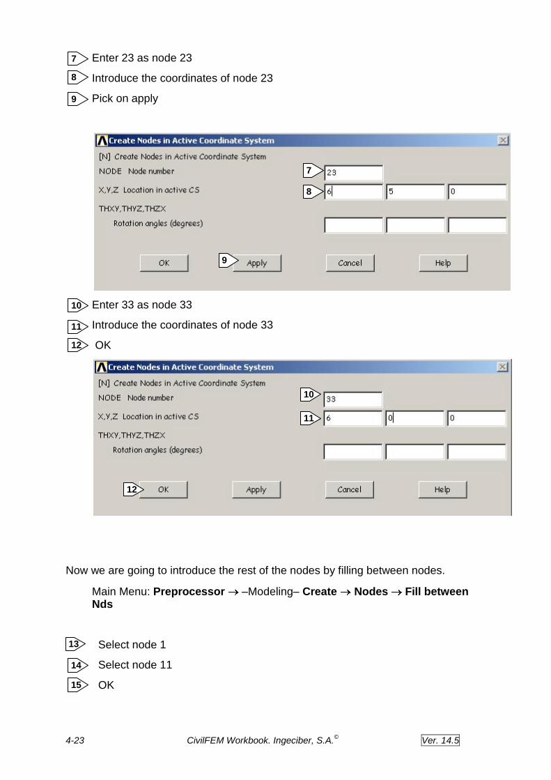
24. Review designed reinforcement for shear force
We are going to plot the designed reinforcement for shear force.
Main Menu: - CivilFEM – Civil Postprocessor Code Checking Eurocode
2 BEAM RESULTS: Plot Results
Choose Shear Design
Choose Area Rnf/Length
OK
1
2
1
2
3
1
2
3
1
2
4-44 CivilFEM Workbook. Ingeciber, S.A.©
Ver. 14.5
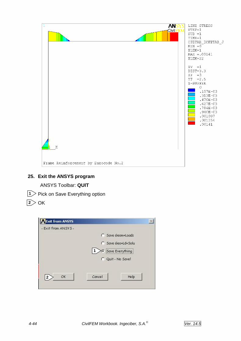
25. Exit the ANSYS program
ANSYS Toolbar: QUIT
Pick on Save Everything option
OK
1
2
1
2