Embed Size (px)
DESCRIPTION
cdfdffdf
Citation preview

n
One of the initial tasks in the preparation of an airport master plan is the collection of information on the
condition of existing facilities and services. This inventory of data is necessary to not only evaluate the
physical attributes of airside and landside infrastructure, but also to complete subsequent study tasks
such as demand/capacity analyses and the determination of facility requirements. Information collected
focuses on the use, size, quantity, type, area, operational intent, and other characteristics of the airside
and landside components of an airport. Typical categories of information that are collected include
history, physical infrastructure, regional setting, surrounding land uses, environmental features, historical
aviation activity, business affairs, and socioeconomic demographics of the surrounding community.
Several sources of information were referenced to compile a comprehensive database of facilities and
services at the Asheville Regional Airport (Airport). These included, but were not limited to, the previous
Airport Master Plan, recent National Environmental Policy Act (NEPA) documents, the Terminal Area
Plan, the Land Use Plan, and the Airport Layout Plan (ALP). In addition, historical enplanements, aircraft
operations, based aircraft, aircraft fleet mix, enplaned cargo, and automobile parking data was obtained
from Federal Aviation Administration (FAA) databases and Airport records. Databases from Woods &
Poole Economics, Inc. provided population, employment, retail sales, and per capita income data for the
11 counties that comprise the Airport’s service area. Finally, an on-site visual inspection of the Airport
was conducted to complete the inventory effort and verify any data discrepancies.
Organized by the following sections, this Chapter summarizes the data that was collected on the
condition of existing Airport facilities and services:
2.1 General Description and Location Information
2.2 History
2.3 Environment and Land Use
2.4 Socioeconomic Data
2.5 Airport Management Structure
2.6 Existing Facilities
2.7 Businesses and Tenants
2.8 Airspace, Air Traffic Control, and Approach/Departure Procedures
2.9 Summary

n
The Asheville Regional Airport is the premier air transportation gateway for Western North Carolina. It is
classified in the National Plan of Integrated Airport Systems (NPIAS) as a primary, small-hub commercial
service airport that is significant to support the aviation demands of the nation’s aviation system. Within
the state aviation system, the North Carolina Department of Transportation (NCDOT) classifies the Airport
as an Air Carrier airport. The Airport holds a Federal Aviation Regulation (FAR) Part 139 operating
certificate, meeting the requirements of a Class I airport capable of serving scheduled and unscheduled
operations of large and small air carrier aircraft. In addition, the Airport meets Aircraft Rescue and Fire
Fighting (ARFF) Index B requirements for firefighting equipment and fire extinguishing agents.
The Airport is located in the Blue Ridge Mountains region of Western North Carolina, approximately ten
miles south of downtown Asheville near the town of Fletcher (Figure 2-1). The property of the Airport
primarily lies within Buncombe County, with a small portion located in Henderson County.
Source: Mead & Hunt
There are four public use, publicly-owned general aviation airports that are in proximity to the Asheville
Regional Airport: the Rutherford County – Marchman Field Airport near Rutherfordton located
approximately 33 miles to the east; the Jackson County Airport near Sylvia located approximately 38
miles to the west; the Avery County – Morrison Field Airport near Spruce Pine located approximately 46

n
miles to the northeast; and the Hickory Regional Airport near Hickory located approximately 68 miles to
the northeast (Figure 2-2). It should be noted that the privately owned public use Hendersonville-Winkler
Airport is located approximately ten miles to the southeast near Hendersonville. Two privately owned,
private use airports are also located near the vicinity of the Asheville Regional Airport: the Transylvania
County Airport near Brevard approximately 12 miles to the southwest and the Wolf Ridge Airport near
Mars Hill approximately 34 miles to the north.
Source: Mead & Hunt, Inc.
Commercial airline service at the Airport is provided by six operators, three of which (Delta Air Lines,
United Airlines, and US Airways) provide service to eight destinations daily. Two airlines, Vision Airlines
and American Eagle, provide daily service seasonally to Ft. Walton Beach, Florida, and Dallas-Ft. Worth,
Texas, respectively, while Allegiant offers service twice a week to the Orlando Sanford International
Airport in Florida. Table 2-1 lists each airline that offers service at the Airport, the destinations they serve,
and the frequency of each arriving and departing flight; Figure 2-3 illustrates the non-stop flights available
from Asheville. It should be noted that AirTran Airways served the Asheville market with daily flights to
Tampa and Orlando, Florida until service was discontinued in January 2012.

n
Note: Destinations and frequency of flights current as of January 2012.
Source: Asheville Regional Airport
Note: Destinations current as of January 2012.
Source: Asheville Regional Airport
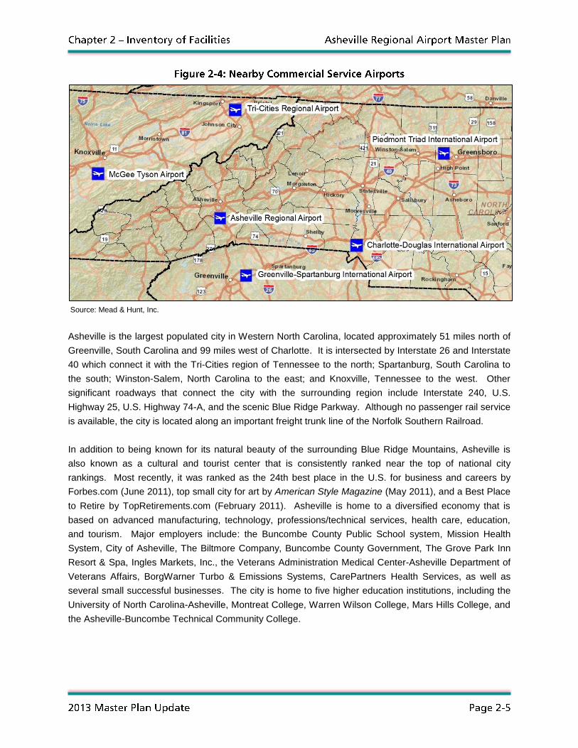
Other airports offering commercial airline service that are nearest to the Asheville region include: the
Greenville-Spartanburg International Airport near Greer, South Carolina located approximately 41 miles to
the south; the Tri-Cities Regional Airport near Blountville, Tennessee located approximately 72 miles to
the north; the McGhee Tyson Airport near Knoxville, Tennessee located approximately 85 miles to the
northwest; the Charlotte Douglas International Airport near Charlotte, North Carolina located
approximately 90 miles to the east; and the Piedmont Triad International Airport in Greensboro, North
Carolina located approximately 152 miles to the northeast (Figure 2-4). The Hartsfield-Jackson Atlanta
International Airport in Atlanta, Georgia located approximately 163 miles to the southwest is also
occasionally used by travelers to access the Western North Carolina region.
n
Source: Mead & Hunt, Inc.
Asheville is the largest populated city in Western North Carolina, located approximately 51 miles north of
Greenville, South Carolina and 99 miles west of Charlotte. It is intersected by Interstate 26 and Interstate
40 which connect it with the Tri-Cities region of Tennessee to the north; Spartanburg, South Carolina to
the south; Winston-Salem, North Carolina to the east; and Knoxville, Tennessee to the west. Other
significant roadways that connect the city with the surrounding region include Interstate 240, U.S.
Highway 25, U.S. Highway 74-A, and the scenic Blue Ridge Parkway. Although no passenger rail service
is available, the city is located along an important freight trunk line of the Norfolk Southern Railroad.
In addition to being known for its natural beauty of the surrounding Blue Ridge Mountains, Asheville is
also known as a cultural and tourist center that is consistently ranked near the top of national city
rankings. Most recently, it was ranked as the 24th best place in the U.S. for business and careers by
Forbes.com (June 2011), top small city for art by American Style Magazine (May 2011), and a Best Place
to Retire by TopRetirements.com (February 2011). Asheville is home to a diversified economy that is
based on advanced manufacturing, technology, professions/technical services, health care, education,
and tourism. Major employers include: the Buncombe County Public School system, Mission Health
System, City of Asheville, The Biltmore Company, Buncombe County Government, The Grove Park Inn
Resort & Spa, Ingles Markets, Inc., the Veterans Administration Medical Center-Asheville Department of
Veterans Affairs, BorgWarner Turbo & Emissions Systems, CarePartners Health Services, as well as
several small successful businesses. The city is home to five higher education institutions, including the
University of North Carolina-Asheville, Montreat College, Warren Wilson College, Mars Hills College, and
the Asheville-Buncombe Technical Community College.
n
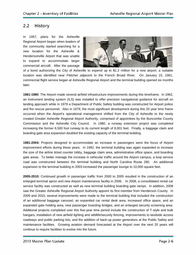
In 1957, plans for the Asheville
Regional Airport began when leaders of
the community started searching for a
new location for the Asheville &
Hendersonville Airport that was unable
to expand to accommodate larger
commercial aircraft. After the passage
of a bond authorizing the City of Asheville to expend up to $1.2 million for a new airport, a suitable
location was identified near Fletcher adjacent to the French Broad River. On January 15, 1961,
commercial flight service began at Asheville Regional Airport and the terminal building opened six months
later.
1961-1980: The Airport made several airfield infrastructure improvements during this timeframe. In 1962,
an instrument landing system (ILS) was installed to offer precision navigational guidance for aircraft on
landing approach while in 1979 a Department of Public Safety building was constructed for Airport police
and fire rescue personnel. Also in 1979, the most significant development during this 20 year time frame
occurred when the Airport’s operational management shifted from the City of Asheville to the newly
created Greater Asheville Regional Airport Authority, comprised of appointees by the Buncombe County
Commission and the Asheville City Council. In 1980, a runway extension project was completed
increasing the former 6,500 foot runway to its current length of 8,001 feet. Finally, a baggage claim and
boarding gate area expansion doubled the existing capacity of the terminal building.
1981-2004: Projects designed to accommodate an increase in passengers were the focus of Airport
improvement efforts during these years. In 1992, the terminal building was again expanded to increase
the size of the airline ticket counter lobby, baggage claim area, administrative office space, and boarding
gate areas. To better manage the increase in vehicular traffic around the Airport campus, a loop service
road was constructed between the terminal building and North Carolina Route 280. An additional
expansion to the terminal building in 2003 increased the passenger lounge to 10,000 square feet.
2005-2010: Continued growth in passenger traffic from 2000 to 2005 resulted in the construction of an
enlarged terminal apron and new Airport maintenance facility in 2006. In 2008, a consolidated rental car
service facility was constructed as well as new terminal building boarding gate ramps. In addition, 2008
saw the Greater Asheville Regional Airport Authority appoint its first member from Henderson County. In
2009 and 2010, several improvements were made to the terminal building that included the construction
of an additional baggage carousel, an expanded car rental desk area, increased office space, and an
expanded gate holding area, new passenger boarding bridges, and an enlarged security screening area.
Additional projects completed over this five-year time period include the construction of T-style and bulk
hangars, installation of new airfield lighting and wildlife/security fencing, improvements to landside access
roadways and public parking lots, and the addition of back-up power generators at the Public Safety and
maintenance facilities. Growing aviation demand forecasted at the Airport over the next 20 years will
continue to require facilities to evolve into the future.
n
In order to plan for future Airport development, an understanding must first be gained of local
environmental conditions and surrounding land uses. Topography, soil type, climate, and local wind
conditions can all factor in determining future infrastructure needs and areas suitable for development
while surrounding land uses can influence growth and expansion opportunities. As part of the inventory
data collection effort, information was gathered on local environmental conditions and a review was
conducted of surrounding land uses. This section summarizes the Airport’s environs and adjacent land
uses.
The review of the Airport’s environs focused on the topography of the surrounding landscape, the types of
soil located on Airport property, historical meteorological conditions, and the average direction and
intensity of local winds. Each one of these environmental elements plays an important role in how future
development occurs at the Airport. A summary of each environ is presented in the following subsections.
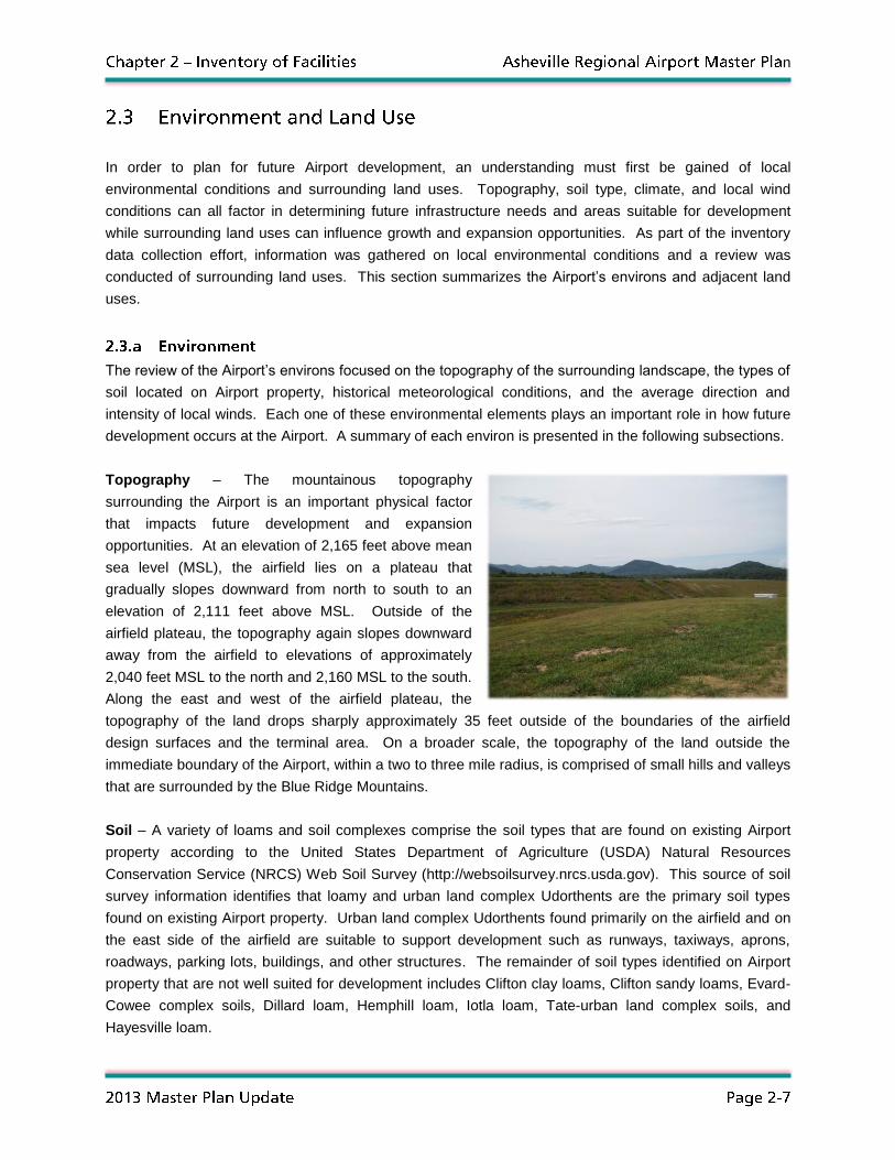
Topography – The mountainous topography
surrounding the Airport is an important physical factor
that impacts future development and expansion
opportunities. At an elevation of 2,165 feet above mean
sea level (MSL), the airfield lies on a plateau that
gradually slopes downward from north to south to an
elevation of 2,111 feet above MSL. Outside of the
airfield plateau, the topography again slopes downward
away from the airfield to elevations of approximately
2,040 feet MSL to the north and 2,160 MSL to the south.
Along the east and west of the airfield plateau, the
topography of the land drops sharply approximately 35 feet outside of the boundaries of the airfield
design surfaces and the terminal area. On a broader scale, the topography of the land outside the
immediate boundary of the Airport, within a two to three mile radius, is comprised of small hills and valleys
that are surrounded by the Blue Ridge Mountains.
Soil – A variety of loams and soil complexes comprise the soil types that are found on existing Airport
property according to the United States Department of Agriculture (USDA) Natural Resources
Conservation Service (NRCS) Web Soil Survey (http://websoilsurvey.nrcs.usda.gov). This source of soil
survey information identifies that loamy and urban land complex Udorthents are the primary soil types
found on existing Airport property. Urban land complex Udorthents found primarily on the airfield and on
the east side of the airfield are suitable to support development such as runways, taxiways, aprons,
roadways, parking lots, buildings, and other structures. The remainder of soil types identified on Airport
property that are not well suited for development includes Clifton clay loams, Clifton sandy loams, Evard-
Cowee complex soils, Dillard loam, Hemphill loam, Iotla loam, Tate-urban land complex soils, and
Hayesville loam.
n
Meteorological/Climate Conditions – Asheville’s latitude, elevation, and the surrounding Blue Ridge
Mountains influence the local climate and meteorological conditions of the region. Though located in a
humid subtropical climate much like the rest of the southeastern United States, temperatures in Asheville
are often cooler as a result of its higher elevation. Summers are warm and humid with the daily maximum
temperature in July averaging 83 degrees Fahrenheit and a low of 63 degrees Fahrenheit. Winters are
cool with below freezing temperatures experienced occasionally as the average daily temperature in
January reaches a high of 46 degrees Fahrenheit and a low of 26 degrees Fahrenheit. Precipitation
totals in Asheville are modest as the region receives approximately 47 inches of rainfall and 13 inches of
snowfall annually. Based on 30 year averages, sunshine is present throughout the region 59 percent of
the year with approximately 97 days experiencing clear skies, 111 days with partly cloudy conditions,
and151 days with overcast skies.
Wind – One of the most important environmental elements at any airport is the direction of local
prevailing winds. Since operational safety is highest when aircraft land and takeoff into the wind, it is
important that the orientations of an airport’s runways are aligned in the same direction as local prevailing
winds. FAA Advisory Circular (AC) 150/5300-13, Airport Design, recommends that the orientation of
runways at an airport provide at least 95 percent wind coverage for types of aircraft using the airport on a
regular basis. This is important since smaller aircraft are greatly impacted by crosswinds, or wind
perpendicular to an aircraft’s path of travel.
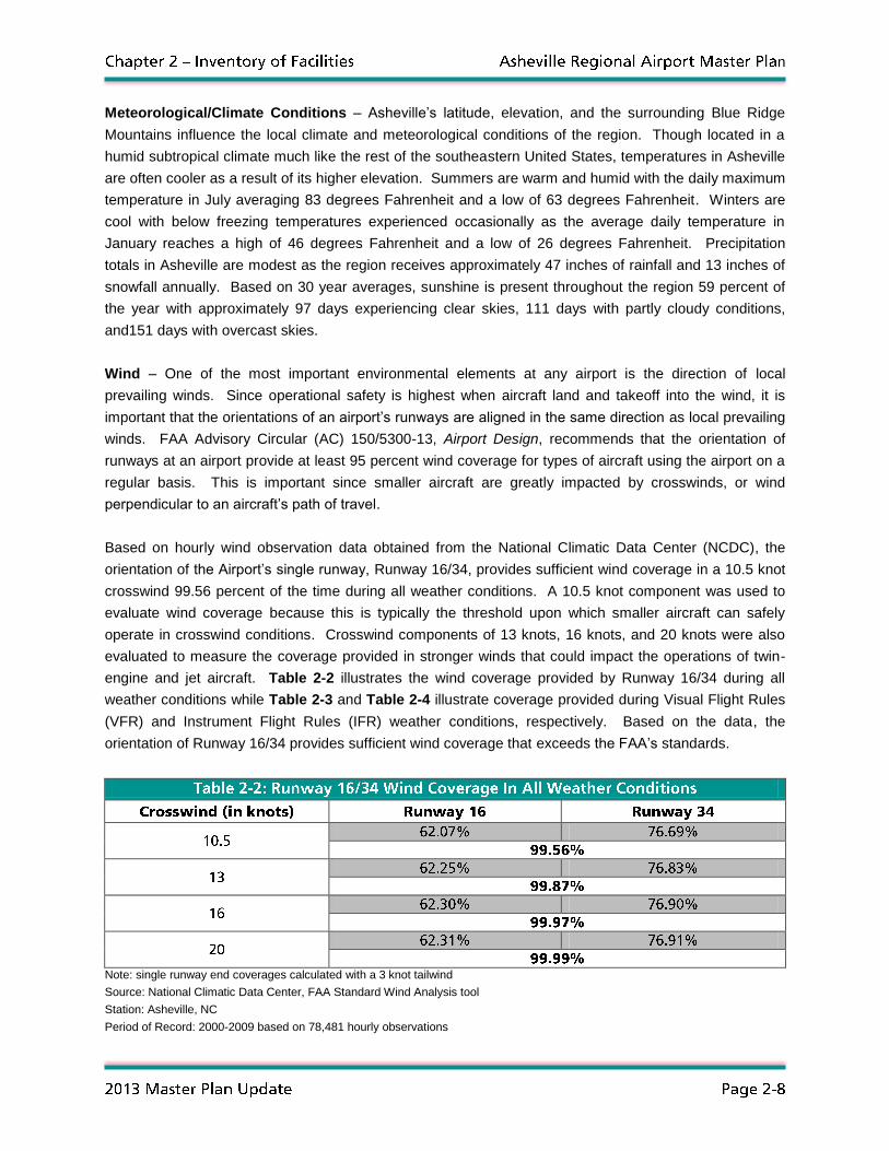
Based on hourly wind observation data obtained from the National Climatic Data Center (NCDC), the
orientation of the Airport’s single runway, Runway 16/34, provides sufficient wind coverage in a 10.5 knot
crosswind 99.56 percent of the time during all weather conditions. A 10.5 knot component was used to
evaluate wind coverage because this is typically the threshold upon which smaller aircraft can safely
operate in crosswind conditions. Crosswind components of 13 knots, 16 knots, and 20 knots were also
evaluated to measure the coverage provided in stronger winds that could impact the operations of twin-
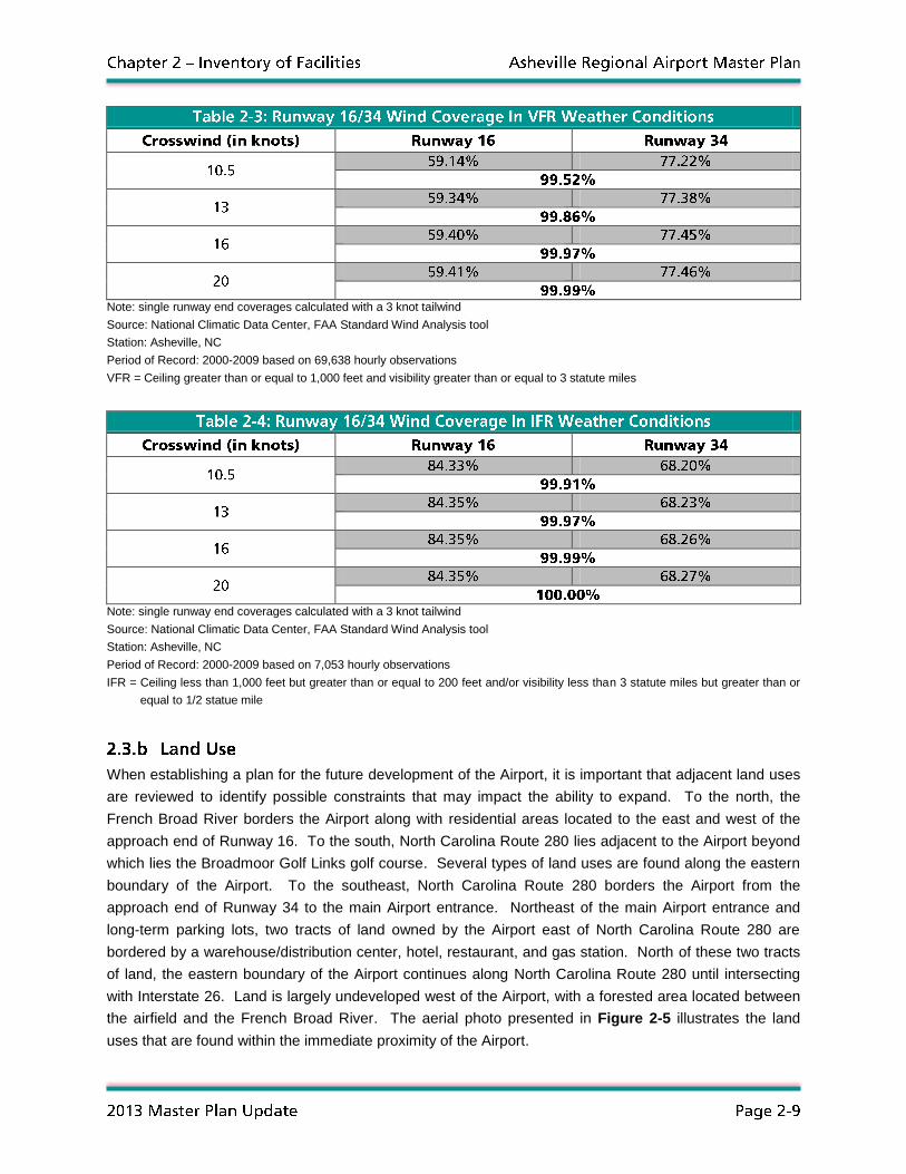
engine and jet aircraft. Table 2-2 illustrates the wind coverage provided by Runway 16/34 during all
weather conditions while Table 2-3 and Table 2-4 illustrate coverage provided during Visual Flight Rules
(VFR) and Instrument Flight Rules (IFR) weather conditions, respectively. Based on the data, the
orientation of Runway 16/34 provides sufficient wind coverage that exceeds the FAA’s standards.
Note: single runway end coverages calculated with a 3 knot tailwind
Source: National Climatic Data Center, FAA Standard Wind Analysis tool
Station: Asheville, NC
Period of Record: 2000-2009 based on 78,481 hourly observations
n
Note: single runway end coverages calculated with a 3 knot tailwind
Source: National Climatic Data Center, FAA Standard Wind Analysis tool
Station: Asheville, NC
Period of Record: 2000-2009 based on 69,638 hourly observations
VFR = Ceiling greater than or equal to 1,000 feet and visibility greater than or equal to 3 statute miles
Note: single runway end coverages calculated with a 3 knot tailwind
Source: National Climatic Data Center, FAA Standard Wind Analysis tool
Station: Asheville, NC
Period of Record: 2000-2009 based on 7,053 hourly observations
IFR = Ceiling less than 1,000 feet but greater than or equal to 200 feet and/or visibility less than 3 statute miles but greater than or
equal to 1/2 statue mile
When establishing a plan for the future development of the Airport, it is important that adjacent land uses
are reviewed to identify possible constraints that may impact the ability to expand. To the north, the
French Broad River borders the Airport along with residential areas located to the east and west of the
approach end of Runway 16. To the south, North Carolina Route 280 lies adjacent to the Airport beyond
which lies the Broadmoor Golf Links golf course. Several types of land uses are found along the eastern
boundary of the Airport. To the southeast, North Carolina Route 280 borders the Airport from the
approach end of Runway 34 to the main Airport entrance. Northeast of the main Airport entrance and
long-term parking lots, two tracts of land owned by the Airport east of North Carolina Route 280 are
bordered by a warehouse/distribution center, hotel, restaurant, and gas station. North of these two tracts
of land, the eastern boundary of the Airport continues along North Carolina Route 280 until intersecting
with Interstate 26. Land is largely undeveloped west of the Airport, with a forested area located between
the airfield and the French Broad River. The aerial photo presented in Figure 2-5 illustrates the land
uses that are found within the immediate proximity of the Airport.

n
Aerial Photo: Woolpert, Inc.
In addition to evaluating existing land uses, it is also important to review the boundaries and locations of
adjacent zoning districts to gain an understanding of future permitted uses of land around the Airport.
Since the Airport is located in both Buncombe and Henderson counties, surrounding land use zoning is
divided between four entities: Buncombe County, the City of Asheville, the Town of Fletcher, and the
Town of Mills River. To the north, as illustrated in Figure 2-6, land within Buncombe County is zoned
primarily for office use, industrial use, storage, warehousing, and wholesale trade (Employment District)
and various residential development that includes low-density and single family uses.

n
Source: Buncombe County GIS Department
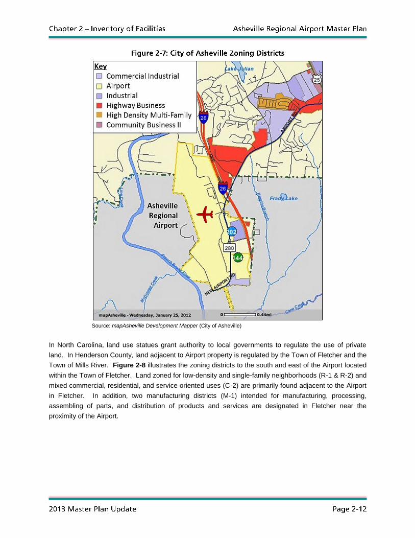
The Airport and an area of land to the northeast lie within the City of Asheville and are subject to the
City’s zoning and land use controls. As illustrated in Figure 2-7, land immediately surrounding the
immediate vicinity of the Airport is zoned for a wide range of commercial and industrial uses such as light
manufacturing, wholesale, warehousing, services, offices, and automobile-oriented commercial
development. In addition, a small area designated for high density multi-family housing types along with
limited institutional, public, and commercial use lies north of the Airport on Airport Road. It should be
noted that Airport land within the City of Asheville is zoned for aviation-related commercial/industrial and
recreational uses.
n
Source: mapAsheville Development Mapper (City of Asheville)
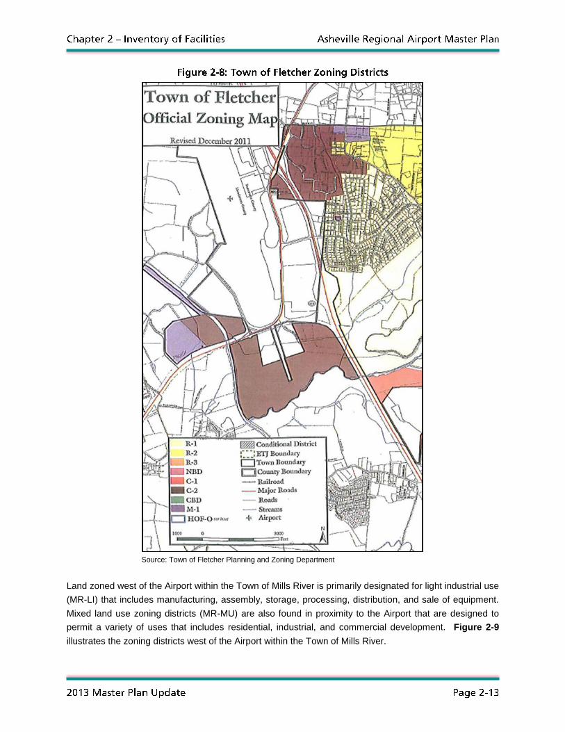
In North Carolina, land use statues grant authority to local governments to regulate the use of private
land. In Henderson County, land adjacent to Airport property is regulated by the Town of Fletcher and the
Town of Mills River. Figure 2-8 illustrates the zoning districts to the south and east of the Airport located
within the Town of Fletcher. Land zoned for low-density and single-family neighborhoods (R-1 & R-2) and
mixed commercial, residential, and service oriented uses (C-2) are primarily found adjacent to the Airport
in Fletcher. In addition, two manufacturing districts (M-1) intended for manufacturing, processing,
assembling of parts, and distribution of products and services are designated in Fletcher near the
proximity of the Airport.
n
Source: Town of Fletcher Planning and Zoning Department
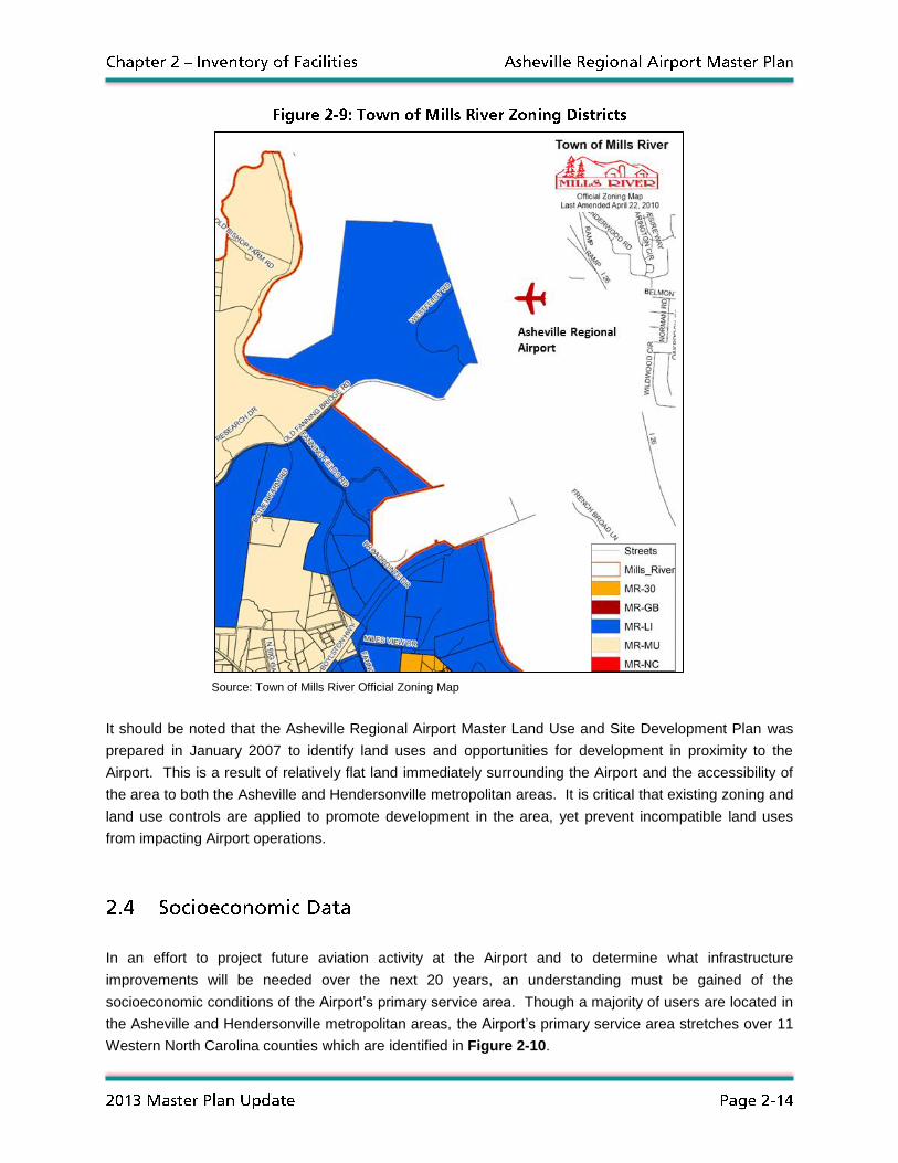
Land zoned west of the Airport within the Town of Mills River is primarily designated for light industrial use
(MR-LI) that includes manufacturing, assembly, storage, processing, distribution, and sale of equipment.
Mixed land use zoning districts (MR-MU) are also found in proximity to the Airport that are designed to
permit a variety of uses that includes residential, industrial, and commercial development. Figure 2-9
illustrates the zoning districts west of the Airport within the Town of Mills River.
n
Source: Town of Mills River Official Zoning Map
It should be noted that the Asheville Regional Airport Master Land Use and Site Development Plan was
prepared in January 2007 to identify land uses and opportunities for development in proximity to the
Airport. This is a result of relatively flat land immediately surrounding the Airport and the accessibility of
the area to both the Asheville and Hendersonville metropolitan areas. It is critical that existing zoning and
land use controls are applied to promote development in the area, yet prevent incompatible land uses
from impacting Airport operations.
In an effort to project future aviation activity at the Airport and to determine what infrastructure
improvements will be needed over the next 20 years, an understanding must be gained of the
socioeconomic conditions of the Airport’s primary service area. Though a majority of users are located in
the Asheville and Hendersonville metropolitan areas, the Airport’s primary service area stretches over 11
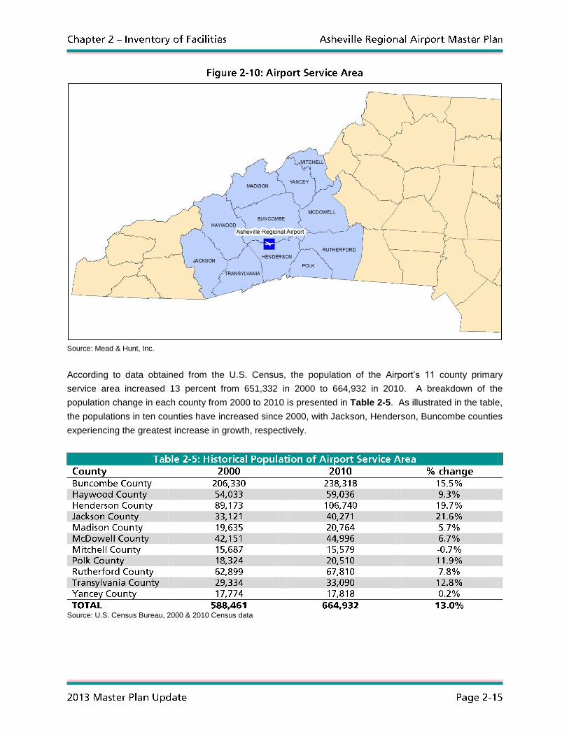
Western North Carolina counties which are identified in Figure 2-10.
n
Source: Mead & Hunt, Inc.
According to data obtained from the U.S. Census, the population of the Airport’s 11 county primary
service area increased 13 percent from 651,332 in 2000 to 664,932 in 2010. A breakdown of the
population change in each county from 2000 to 2010 is presented in Table 2-5. As illustrated in the table,
the populations in ten counties have increased since 2000, with Jackson, Henderson, Buncombe counties
experiencing the greatest increase in growth, respectively.
Source: U.S. Census Bureau, 2000 & 2010 Census data

n
According to 2010 U.S. Census data, 36 percent of the Airport’s service area population lives within
Buncombe County, followed by Henderson County with 16 percent and Rutherford County with 10
percent. Demographically, 51 percent of the population is between the ages of 20 and 59 followed by
persons 60 years of age and older at 26 percent and 19 years of age and under at 23 percent. Table 2-6
illustrates the breakdown in age demographics for the 11 counties that comprise the Airport’s service
area.
Source: U.S. Census Bureau, 2010 Census data
The mean household total personal income offers a method to summarize the economic demographics of
the population within the Airport’s service area. Since 2000, the mean household total income has
fluctuated with some counties experiencing an increase in their average income while others have
decreased. Table 2-7 compares the mean household total personal income for each county that
comprises the Airport’s service area from 2000 to 2010. Data from Woods & Poole Economics, Inc.
indicates that the greatest increase in average total household personal income from 2000 to 2010
occurred in Rutherford County at 4.8 percent while the greatest decrease occurred in Yancey County at
minus 9.1 percent. It is interesting to note that the average of the mean household total personal income
for all counties within the Airport’s service area between 2000 and 2010 has remained constant.
Source: Woods & Poole Economics, Inc. (in 2004 dollars)
n
The management of the Asheville Regional Airport is overseen by the Greater Asheville Regional Airport
Authority Board, which was founded in 1979 and is charged with the maintenance, operation, and
development of the Airport. The Board includes seven members, three of which are appointed by the
Asheville City Council and three of which are appointed by the Buncombe County Board of
Commissioners. A seventh member is selected by the six Authority Board appointees as the At-Large
member.
The Airport Director, with support from the Authority Legal Counsel, General Consultants, and Airport
staff, reports to the Authority Board. The Airport Director is assisted by the Director of Finance and
Accounting, the Director of Administration, the Director of Marketing and Public Relations, and the
Director of Information Technology who are responsible for Airport administrative tasks. These positions
are also supported by coordinators, supervisors, and assistants who are responsible for more specific
administrative tasks.
The Airport Director is also supported by the Deputy Airport Director of Development and Operations who
oversees operations, maintenance, public safety, and the management of capital development projects at
the Airport. Reporting to the Deputy Airport Director of Development and Operations are the Director of
Operations and Maintenance and the Chief of Public Safety who oversee supervisors, coordinators,
technicians, and officers responsible for specific Airport tasks. In all, the Airport Authority is comprised of
60 full-time employees. Figure 2-11 illustrates the organizational structure of Greater Asheville Regional
Airport Authority staff.

n
Source: Greater Asheville Regional Airport Authority
n
A majority of the inventory effort focused on the collection of information related to airside and landside
facilities, along with the aviation support infrastructure necessary to ensure the safe and efficient
operation of the Airport. This library of information that was collected offered a baseline that was used to
complete subsequent study analyses in an effort to determine what will be needed over the next 20 years
to meet anticipated future aviation demand. This section summarizes the data that was collected related
to airside facilities (such as runways, taxiways, aprons, and navigational aids), aviation support facilities
(such as the terminal building, hangars, air traffic control tower (ATCT), Aircraft Rescue and Fire Fighting
(ARFF) station, and maintenance vehicle garage), and landside facilities (such as access roads, parking
lots, and the rental car service facility).
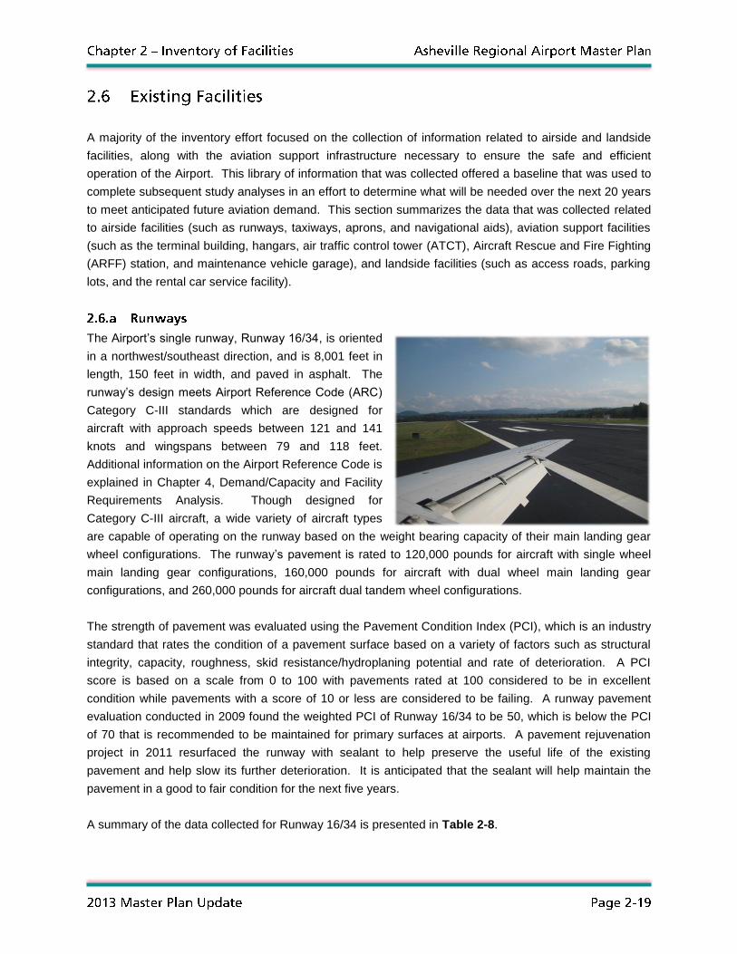
The Airport’s single runway, Runway 16/34, is oriented
in a northwest/southeast direction, and is 8,001 feet in
length, 150 feet in width, and paved in asphalt. The
runway’s design meets Airport Reference Code (ARC)
Category C-III standards which are designed for
aircraft with approach speeds between 121 and 141
knots and wingspans between 79 and 118 feet.
Additional information on the Airport Reference Code is
explained in Chapter 4, Demand/Capacity and Facility
Requirements Analysis. Though designed for
Category C-III aircraft, a wide variety of aircraft types
are capable of operating on the runway based on the weight bearing capacity of their main landing gear
wheel configurations. The runway’s pavement is rated to 120,000 pounds for aircraft with single wheel
main landing gear configurations, 160,000 pounds for aircraft with dual wheel main landing gear
configurations, and 260,000 pounds for aircraft dual tandem wheel configurations.
The strength of pavement was evaluated using the Pavement Condition Index (PCI), which is an industry
standard that rates the condition of a pavement surface based on a variety of factors such as structural
integrity, capacity, roughness, skid resistance/hydroplaning potential and rate of deterioration. A PCI
score is based on a scale from 0 to 100 with pavements rated at 100 considered to be in excellent
condition while pavements with a score of 10 or less are considered to be failing. A runway pavement
evaluation conducted in 2009 found the weighted PCI of Runway 16/34 to be 50, which is below the PCI
of 70 that is recommended to be maintained for primary surfaces at airports. A pavement rejuvenation
project in 2011 resurfaced the runway with sealant to help preserve the useful life of the existing
pavement and help slow its further deterioration. It is anticipated that the sealant will help maintain the
pavement in a good to fair condition for the next five years.
A summary of the data collected for Runway 16/34 is presented in Table 2-8.

n
Source: Airport Layout Plan
Taxiways are defined pavement surfaces used for aircraft to travel safely between the runway and other
airfield destinations such as aprons, hangars, and terminals. An airport’s taxiway configuration should be
designed to efficiently move aircraft between points on the airfield and minimize the amount of time an
aircraft occupies a runway prior to takeoff or after landing. As a result of having a single runway and a
linear organization of facilities, the taxiway configuration at the Airport is relatively simple and is
comprised of a parallel taxiway, connector taxiways, and high speed exit taxiways. The Airport’s parallel
taxiway, Taxiway A, extends the entire length of Runway 16/34 and is 75 feet in width. Connector
taxiways, such as Taxiway B, Taxiway F, Taxiway N, and Taxiway R, intersect the parallel taxiway or
runway perpendicularly, connecting airfield destinations and the runway with the taxiway system. Finally,
high speed exit taxiways such as Taxiway E, Taxiway M, and Taxiway P offer aircraft an acute angle to
quickly exit the runway after landing, increasing its throughput capacity during periods of frequent aircraft
operations. Figure 2-12 illustrates the taxiway configuration at the Airport.
Aerial Photo: Woolpert, Inc.
Aprons, also known as ramps, are large paved surfaces designed for the parking and servicing of aircraft.
Aprons provide access to terminal, hangar, and fixed base operator (FBO) facilities, locations to transfer
passengers and cargo from aircraft, and areas for aircraft fueling and maintenance. The size and
pavement strength of an apron varies upon several factors that include the fleet mix of aircraft intended to
use the surface, available space, special aircraft servicing needs, and the configurations of terminals,

n
hangars, and FBOs. The Airport has four primary aprons that serve the main terminal building, the FBO,
and the numerous corporate and private hangars based on the airfield. The terminal apron,
approximately 417,100 square feet in area, is located adjacent to the main terminal building and is
intended for the exclusive use of commercial airlines to transfer passengers and luggage to and from
aircraft. This apron is also intended for the commercial airlines to service, fuel, and deice aircraft. The
north apron offers parking locations for transient aircraft as well as access to the Landmark Aviation FBO.
The south apron, approximately 357,400 square feet in area, is located north of the terminal apron and
provides access to box-style aircraft hangars that house both corporate and private aircraft. The apron
area located between the north and south aprons is referred to as the middle-ramp, or mid-ramp, and
offers access to the three T-hangar structures as well as tie down locations for based and itinerant
aircraft.
It should be noted that two helicopter parking aprons are located adjacent to the south apron and middle
ramp. Though these surfaces may be referred to as helipads in some documents, they are primarily
designed for the parking and servicing of itinerant helicopters since they are located within the non-
movement area of the airfield. In accordance with air traffic control (ATC) instructions, helicopters are
expected to take off and land at the Airport from the parallel taxiway or runway and hover or ground taxi
to and from the helicopter parking aprons.
Figure 2-13 illustrates the locations of the four apron areas and two helicopter parking locations at the
Airport.
Aerial Photo: Woolpert, Inc.
Navigational aids (NAVAIDs) are forms of visual and electronic equipment designed to assist pilots in
identifying and navigating to an Airport. Ranging from devices that help a pilot visually identify the

n
location of an airport to those that provide the correct glide path and angle of descent for landing on a
runway, NAVAIDs are most useful in nighttime conditions or when a pilot’s visibility is limited. NAVAIDs
that emit electronic signals are especially useful to pilots operating properly equipped aircraft when
navigating an approach to an airport in poor visibility weather conditions. While most NAVAIDs are
ground-based equipment that are installed on an airfield, some are satellite-based that provide
navigational signals for properly equipped aircraft. This section reviews both the ground-based and
satellite-based visual and electronic NAVAID equipment available for aircraft operations at the Airport.
Visual NAVAIDs – Visual NAVAIDs are those that allow a pilot to visually identify the airfield on approach
to landing, when taxiing after landing or prior to takeoff. Visual NAVAIDs range from lighting equipment to
signs identifying airfield locations and devices that indicate the strength and direction of the wind. The
following visual NAVAIDs are located at the Airport:
Rotating Beacon – A rotating beacon is a high intensity light that rotates 360 degrees and is
operated at night and in inclement weather conditions to assist pilots in identifying the location of
an airport from a distance in the air. The beacon is equipped with a green and a white lens
separated 180 degrees from one another that emits alternating white and green flashes indicating
an airport is available for public use. The rotating beacon at the Airport is located on the top of
the ATCT.
Wind Indicators – Wind indicators, also known as wind socks, are orange fabric cones that
indicate the strength and direction of the wind. These NAVAIDs assist pilots in making
navigational corrections to adjust for surface prevailing winds moments before touchdown or prior
to departure. Wind cones are required to be located approximately 1,000 feet from the end of
each runway that serves air carrier aircraft and are to be lighted if an airport is open to
commercial air carrier operations at night. Three lighted wind indicators are located at the Airport:
one inside the segmented circle adjacent to the south ramp, one adjacent to the glide slope
antenna on the approach end of Runway 16, and one adjacent to the glide slope antenna on the
approach end of Runway 34.
Segmented Circle – A segmented circle is a ground based
marking indicating the traffic pattern, wind direction, and wind
strength to pilots en route. A segmented circle features a
series of white or orange markings arranged in a circle with
traffic pattern indicators protruding from the circle to specify
the direction of the traffic pattern. A lighted wind indicator is
placed inside the segmented circle markings to indicate the
direction and intensity of the wind. The segmented circle at
the Airport is located adjacent to the south ramp and includes
two “L” shaped traffic pattern indicators separated 180 degrees away from one another to indicate
the right traffic pattern for Runway 34.

n
MALSR – Medium Intensity Approach Lighting System with Runway Alignment Indicator Lights
(MALSR) assists pilots in visually acquiring the centerline of a runway prior to its threshold.
MALSRs are most beneficial to pilots when aligning an aircraft with a runway centerline moments
before touchdown during inclement weather and night time conditions when visibility is limited. A
typical MALSR arrangement consists of nine light bars, each with five lights that are preceded by
five sequenced flashing (SF) lights. At the Airport, MALSRs are located one at each approach
end of Runway 16/34.
VASI – Visual Approach Slope Indicators (VASIs) are lighting systems that indicate the correct
glide path to pilots when on approach to a runway. A combination of red and white lights emitted
from the VASI allows pilots to identify whether they are above, below, or on path with the correct
glide slope. VASIs are typically a two bar, four-light unit located adjacent to the runway near the
touchdown point aiming point marking. At the Airport, a four-light unit VASI is located on the
approach end of Runway 34.
PAPI – Precision Approach Path Indicators (PAPIs) are a more simplified version of a VASI that
also indicate the correct glide slope to pilots. Like VASIs, the correct glide path is indicated by a
combination of red and white lights that identify whether a pilot is above, below, or on path with
the correct glide slope. PAPIs are typically comprised of a two- or four-light unit located adjacent
to the touchdown zone aiming point marking of a runway. A four-light PAPI is located at the
Airport on the approach end of Runway 16.
Runway Edge Lighting – Runway edge lighting serves as an important navigational tool for
pilots as it helps pilots identify the edge of the runway pavement surface during night and in low
visibility weather conditions. This NAVAID is used by pilots to help align an aircraft with the
centerline of a runway and in judging the distance remaining after touchdown and during takeoff.
Runway edge lights are white except for the last 2,000 feet of an instrument runway when edge
lighting is amber in color to help pilots identify the end of the pavement surface.
Runway edge lights are classified into three types of lighting systems: High Intensity Runway
Lights (HIRL), Medium Intensity Runway Lights (MIRL), and Low Intensity Runway Lights (LIRL).
HIRL systems offer the greatest illumination intensity with five light intensity settings while MIRL
systems offer three light intensity settings and LIRL systems typically have a single intensity
setting. Runway 16/34 at the Airport is equipped with a HIRL system that can be controlled
remotely by the pilot through a series of microphone keys on the Common Traffic Advisory
Frequency (CTAF) when the ATCT is closed between 11:00 p.m. and 6:30 a.m. daily.
Runway Centerline Lights – Runway centerline lights are located in the pavement of a runway
along its centerline to assist pilots in visually identifying the center of a runway. In addition to
helping pilots position an aircraft laterally on a runway during takeoff and landing, runway
centerline lights are also used as an indicator to judge the distance remaining on a runway.
Runway centerline lights are white and extend the entire distance of a runway until the last 3,000
n
feet when red and white lights alternate. For the remaining 1,000 feet, runway centerline lights
are entirely red. Runway 16/34 is equipped with runway centerline lighting in both directions.
Runway Touchdown Zone Lights – Runway touchdown zone (TDZ) lighting is another in-
pavement lighting system utilized by pilots when on approach to a runway to identify the location
of the touchdown zone. This lighting system is especially beneficial to pilots when locating the
landing zone of a runway during nighttime and low visibility conditions. Runway TDZ lights
consist of two rows of traversing three bars, each with three unidirectional lights that extend down
the runway from the beginning of the touchdown zone to a distance of 3,000 feet. At the Airport,
Runway 34 is equipped with TDZ lighting.
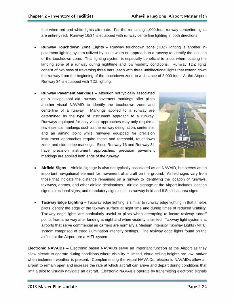
Runway Pavement Markings – Although not typically associated
as a navigational aid, runway pavement markings offer pilots
another visual NAVAID to identify the touchdown zone and
centerline of a runway. Markings applied to a runway are
determined by the type of instrument approach to a runway.
Runways equipped for only visual approaches may only require a
few essential markings such as the runway designation, centerline,
and an aiming point while runways equipped for precision
instrument approaches require these and threshold, touchdown
zone, and side stripe markings. Since Runway 16 and Runway 34
have precision instrument approaches, precision pavement
markings are applied both ends of the runway.
Airfield Signs – Airfield signage is also not typically associated as an NAVAID, but serves as an
important navigational element for movement of aircraft on the ground. Airfield signs vary from
those that indicate the distance remaining on a runway to identifying the location of runways,
taxiways, aprons, and other airfield destinations. Airfield signage at the Airport includes location
signs, directional signs, and mandatory signs such as runway hold and ILS critical area signs.
Taxiway Edge Lighting – Taxiway edge lighting is similar to runway edge lighting in that it helps
pilots identify the edge of the taxiway surface at night time and during times of reduced visibility.
Taxiway edge lights are particularly useful to pilots when attempting to locate taxiway turnoff
points from a runway after landing at night and when visibility is limited. Taxiway light systems at
airports that serve commercial air carriers are normally a Medium Intensity Taxiway Lights (MITL)
system comprised of three illumination intensity settings. The taxiway edge lights found on the
airfield at the Airport are a MITL system.
Electronic NAVAIDs – Electronic based NAVAIDs serve an important function at the Airport as they
allow aircraft to operate during conditions where visibility is limited, cloud ceiling heights are low, and/or
when inclement weather is present. Complementing the visual NAVAIDs, electronic NAVAIDs allow an
airport to remain open and increase the rate at which aircraft can arrive and depart during conditions that
limit a pilot to visually navigate an aircraft. Electronic NAVAIDs operate by transmitting electronic signals
n
which are received by avionic equipment installed on an aircraft providing position, altitude, and speed
information which allows a properly trained and certified pilot to navigate an aircraft using the
instrumentation in the cockpit. Methods of providing electronic navigational information range from
ground-based transmitters installed on the airfield of an airport to satellites orbiting the Earth. Electronic
NAVAIDs utilized at the Airport are listed in the following subsection:
Instrument Landing System – Instrument Landing Systems (ILS) are electronic NAVAIDs that
provide precision vertical and horizontal position information for aircraft on approach to a runway.
An ILS is comprised of two pieces of equipment: a localizer and a glide slope antenna. Localizers
are positioned at the departure end of a runway and transmit a signal that allows aircraft to align
with the centerline of a runway when on approach to land. Signals transmitted from glide slope
antennas position aircraft vertically with the correct glide slope path as they descend for landing
on a runway. An ILS is the most precise navigational guidance systems of all electronic
NAVAIDs.
There are different categories of ILSs based upon their navigational accuracy, decision height,
and visibility requirements. The standard ILS, Category I, allows a properly equipped aircraft to
conduct an approach to a runway when the ceiling is not lower than 200 feet and the visibility is
not lower than a 1/2 mile. At the Airport, Runway 16 and Runway 34 are equipped with Category
I ILSs.
Global Positioning System (GPS) – The Global Positioning System (GPS) is a satellite based
navigational system that allows aircraft equipped with GPS receivers to accurately determine their
location, altitude, direction of travel, and velocity. GPS offers aircraft the ability to conduct non-
precision instrument approaches to runways without the use of ground based navigational
equipment. With the installation of ground based GPS equipment, aircraft can receive more
precise navigational information to conduct a near precision Localizer Performance with Vertical
Guidance (LPV) instrument approach. Aircraft are able to conduct LPV GPS approaches at the
Airport to both Runway 16 and Runway 34.
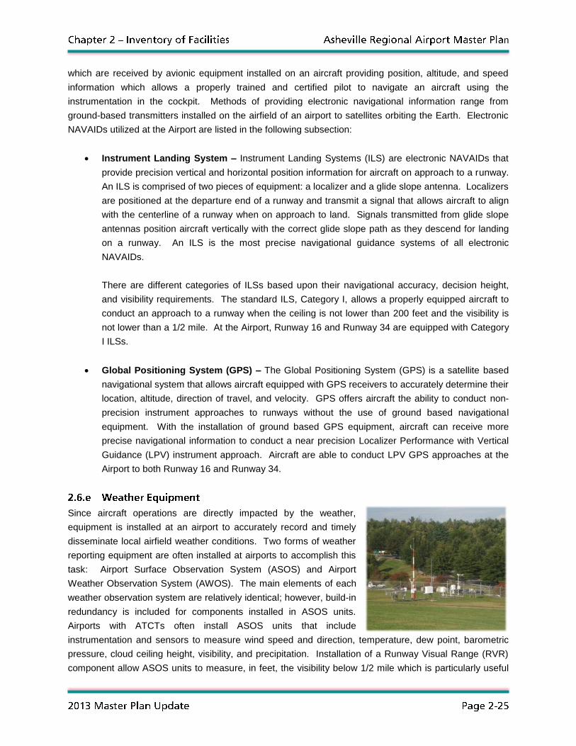
Since aircraft operations are directly impacted by the weather,
equipment is installed at an airport to accurately record and timely
disseminate local airfield weather conditions. Two forms of weather
reporting equipment are often installed at airports to accomplish this
task: Airport Surface Observation System (ASOS) and Airport
Weather Observation System (AWOS). The main elements of each
weather observation system are relatively identical; however, build-in
redundancy is included for components installed in ASOS units.
Airports with ATCTs often install ASOS units that include
instrumentation and sensors to measure wind speed and direction, temperature, dew point, barometric
pressure, cloud ceiling height, visibility, and precipitation. Installation of a Runway Visual Range (RVR)
component allow ASOS units to measure, in feet, the visibility below 1/2 mile which is particularly useful

n
to pilots operating in Instrument Flight Rules (IFR) weather conditions. An ASOS unit with RVR
capabilities is located at the Airport east of Taxiway A and north of the rental car service facility.
Surrounding the Airport, seven Low Level Wind Shear Alert System (LLWAS) sensor towers have been
installed to notify pilots and ATC officials when this weather phenomenon is present. Wind shears are
sudden changes in velocity or direction that are usually associated with warm or cold fronts, low level jet
streams, and mountainous terrain. A strong wind shear can quickly alter the airspeed and path of travel
of an aircraft that may result in a dangerous loss of lift. To warn pilots when these dangerous wind
conditions are present, the seven wind shear indicators are located around the Airport.
Also installed at the Airport is a SCAN Web internet-based weather system that provides a snapshot of
real-time weather information collected from ASOS instrumentation and in-pavement runway sensors.
The system displays weather information such as air temperature, ground temperature, dew point,
relative humidity, precipitation, wind speed, wind direction, and visibility for designated locations across
the airfield. SCAN Web is particularly useful during snow and ice removal operations as in-pavement
sensors on Runway 16/34 can measure the temperature of the pavement and help determine when
precipitation may begin to freeze. This information helps Airport maintenance staff determine when to
expect snow accumulation on the runway and when to apply deicing and anti-icing agents. The SCAN
Web system at the Airport can be accessed by approved personnel through a secure web address on any
internet browsing software.
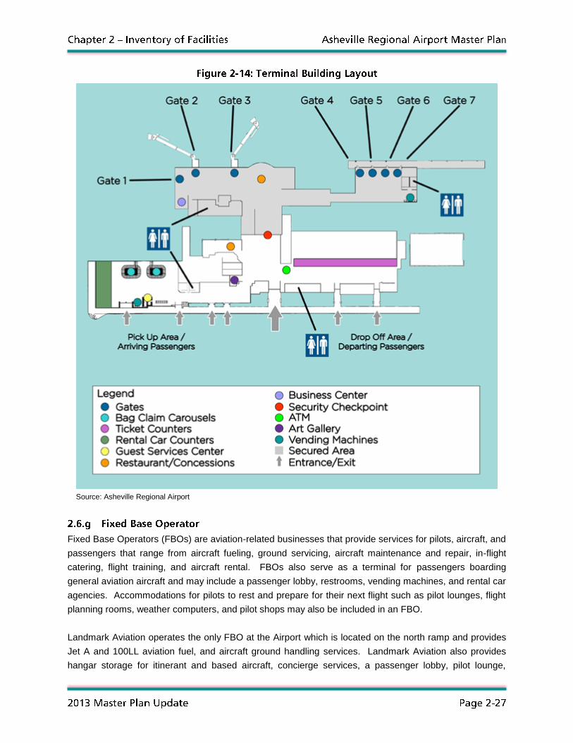
The main terminal building at the Airport is a seven gate facility equipped with five passenger boarding
bridges, two baggage claim devices, and a single security checkpoint. Airline ticket counters are located
in the north wing of the terminal on the public side of the security screening checkpoint while the baggage
claims, rental car counters, and a guest services desk are located in the south wing. Prior to entering the
security checkpoint, a concession stand is located next to the exit lane offering magazines, newspapers,
snacks, and other travel items for purchase. On the secured side of the screening checkpoint, the Blue
Ridge Trading + Tavern provides passengers with a full-service restaurant and bar while the gift shop
sells reading materials, travel essentials, merchandise, and souvenirs. A business center located post
screening near Boarding Gate 1 offers travelers a quiet area to complete work and other tasks. Figure 2-
14 illustrates the floor plan of the terminal building and its features.
Inside the terminal, artwork from Western North Carolina artists is displayed on a rotating basis.
Sculptors and painters are encouraged to apply with the Airport to have their work displayed throughout
the terminal and within the art gallery located near the security screening checkpoint. In addition to
displaying art work, a piano purchased by the Airport in the terminal is available for musicians from
pianists to folk ensembles to use if they apply with the Airport.
It should also be noted that the Airport’s control tower is located on the top of the terminal building
complex. Further discussion about the ATCT is presented in Section 2.8 of this Chapter.
n
Source: Asheville Regional Airport
Fixed Base Operators (FBOs) are aviation-related businesses that provide services for pilots, aircraft, and
passengers that range from aircraft fueling, ground servicing, aircraft maintenance and repair, in-flight
catering, flight training, and aircraft rental. FBOs also serve as a terminal for passengers boarding
general aviation aircraft and may include a passenger lobby, restrooms, vending machines, and rental car
agencies. Accommodations for pilots to rest and prepare for their next flight such as pilot lounges, flight
planning rooms, weather computers, and pilot shops may also be included in an FBO.
Landmark Aviation operates the only FBO at the Airport which is located on the north ramp and provides
Jet A and 100LL aviation fuel, and aircraft ground handling services. Landmark Aviation also provides
hangar storage for itinerant and based aircraft, concierge services, a passenger lobby, pilot lounge,

n
conference room, and flight planning services. In addition, Landmark Aviation also oversees the leasing
of several private general aviation hangars and tie-down spaces on both the north and south ramps.
Figure 2-15 illustrates Landmark Aviation’s FBO terminal facility and its main hangar.
Source: Mead & Hunt, Inc.
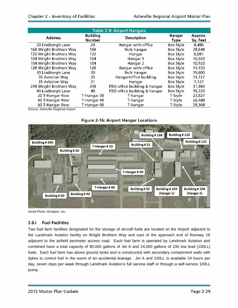
Hangars are enclosed structures for the parking, servicing, and maintenance of aircraft and are designed
for the protection of aircraft from environmental elements such as wind, rain, snow, ice, dust, and shelter-
seeking small animals and birds. Most aircraft hangar structures are either box-style or T-style designs.
Box-style hangars have a rectangular or box-shaped building footprint that range in size from structures
that can house one or two single-engine aircraft to those capable of accommodating multiple jet aircraft.
T-style hangars, also known as T-hangars, are in essence a series of small, interconnected single-engine
aircraft hangars with footprints in the shape of a “T”. Box-style hangars are most often constructed for
multi-engine and jet aircraft while T-hangars are a popular covered storage option for multi- and single-
engine aircraft.
Several box-style hangars are located on both the north and south ramps at the Airport while three T-style
hangar structures are found on the north ramp. Table 2-9 lists the hangars found at the Airport while
Figure 2-16 identifies their location.
n
Source: Asheville Regional Airport
Aerial Photo: Woolpert, Inc.
Two fuel farm facilities designated for the storage of aircraft fuels are located on the Airport adjacent to
the Landmark Aviation facility on Wright Brothers Way and east of the approach end of Runway 16
adjacent to the airfield perimeter access road. Each fuel farm is operated by Landmark Aviation and
combined have a total capacity of 80,000 gallons of Jet A and 24,000 gallons of 100 low lead (100LL)
fuels. Each fuel farm has above ground tanks and is constructed with secondary containment walls with
dykes to control fuel in the event of an accidental leakage. Jet A and 100LL is available 24 hours per
day, seven days per week through Landmark Aviation’s full service staff or through a self-service 100LL
pump.

n
In addition to the two aviation fuel farms, three other fueling facilities for non-aviation related purposes are
located at the Airport. A fuel farm with a capacity of 1,800 gallons of diesel fuel and 1,800 gallons of
unleaded gasoline is located within the airfield maintenance facility that is utilized by the Airport to refuel
vehicles, tractors, snow removal equipment, and ARFF vehicles. A second non-aviation related fuel farm
is located at the rental car maintenance facility at the south end of the Airport and is utilized by the rental
car agencies for the refueling of rental vehicles. This fuel farm has five above ground, double-walled
5,000 gallon unleaded gasoline tanks that have a total capacity of 25,000 gallons. The third non-aviation
fuel farm is located on the south side of the terminal building complex and consists of a single 8,000
gallon double-walled diesel fuel tank. This tank supplies diesel to the several emergency power
generators located adjacent to the terminal that provide electricity to airfield lighting and other essential
electrical components in the event of a power failure.
US Airways operates an air cargo processing facility for
small packages in a building located adjacent to the ARFF
building on the north side on the main terminal apron.
Customers that have established shipping accounts with
US Airways are able to drop off and pick up freight at the
facility during standard business hours Monday through
Friday for transport aboard the US Airways commercial
passenger jets and small single- and twin-engine general
aviation aircraft. The building has a total of eight roll up doors, four facing airside and four facing
landside.
It should be noted that the Airport is utilizing coal-combustion by products (CCBs) for an engineered fill
project on the west side of the airfield adjacent to the approach end of Runway 34 to create additional
areas for future development. While a future use for this area has not yet been officially determined, it is
anticipated that additional air cargo facilities may be constructed at this location. Given the close
proximity of a FedEx Freight processing facility southwest of the airfield, continued efforts to prepare this
area for future development may attract additional air cargo and freight processing facilities.
The Airport’s maintenance facility for vehicles, equipment, and personnel is located landside near the
intersection of Aviation Way and Wright Brothers Way. The three-building facility features storage and
service areas for equipment, vehicle bays, workspaces, and personnel areas for Airport maintenance
staff. The maintenance bay facility includes multiple bays for equipment servicing and includes a vehicle
lift, overhead crane, and retractable pressurized air, electrical, and vehicle fluid hose reels. A personnel
area adjacent to the maintenance bay facility provides staff with workspaces, offices, restrooms/showers,
lockers, a kitchen, lounge, and sleeping quarters for staff use. Two additional multiple bay facilities
provide covered storage for snow removal equipment, tractors, vehicles, mowers, supplies, and snow
removal raw material storage.
n
Several vehicles and self-propelled machines are utilized by the Airport’s maintenance department to
maintain and keep the airfield operational. In addition to pickup trucks, tractors, mowers, fork lifts, and
front end loaders, the Airport’s maintenance vehicle inventory also includes rotary cutters, sweepers, and
tandem axle snowplow trucks. Table 2-10 lists the inventory of maintenance vehicles and other pieces of
self-propelled equipment at the Airport.
Source: Asheville Regional Airport
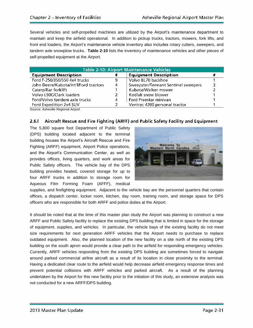
The 5,800 square foot Department of Public Safety
(DPS) building located adjacent to the terminal
building houses the Airport’s Aircraft Rescue and Fire
Fighting (ARFF) equipment, Airport Police operations,
and the Airport’s Communication Center, as well as
provides offices, living quarters, and work areas for
Public Safety officers. The vehicle bay of the DPS
building provides heated, covered storage for up to
four ARFF trucks in addition to storage room for
Aqueous Film Forming Foam (AFFF), medical
supplies, and firefighting equipment. Adjacent to the vehicle bay are the personnel quarters that contain
offices, a dispatch center, locker room, kitchen, day room, training room, and storage space for DPS
officers who are responsible for both ARFF and police duties at the Airport.
It should be noted that at the time of this master plan study the Airport was planning to construct a new
ARFF and Public Safety facility to replace the existing DPS building that is limited in space for the storage
of equipment, supplies, and vehicles. In particular, the vehicle bays of the existing facility do not meet
size requirements for next generation ARFF vehicles that the Airport needs to purchase to replace
outdated equipment. Also, the planned location of the new facility on a site north of the existing DPS
building on the south apron would provide a clear path to the airfield for responding emergency vehicles.
Currently, ARFF vehicles responding from the existing DPS building are sometimes forced to navigate
around parked commercial airline aircraft as a result of its location in close proximity to the terminal.
Having a dedicated clear route to the airfield would help decrease airfield emergency response times and
prevent potential collisions with ARFF vehicles and parked aircraft. As a result of the planning
undertaken by the Airport for this new facility prior to the initiation of this study, an extensive analysis was
not conducted for a new ARFF/DPS building.
n
ARFF services at the Airport are provided by three vehicles that meet Index B requirements as outlined in
FAR Part 139; an E-One Crash Truck, an Oshkosh Crash Truck, and an Oshkosh Striker 1500. At all
times, two of these vehicles comprise the active duty fleet at the Airport while the third is maintained as a
reserve vehicle in the event additional vehicles are needed for an emergency. A fourth fire truck, a
Walters 4x4 Crash Truck, will be taken out of service in 2012 and replaced with a 2012 Rosenbauer
Rapid Intervention Vehicle which is on order. In addition to these vehicles, a Polaris Ranger all-terrain
vehicle (ATV) is used to access locations on the Airport that may be difficult to reach with the larger
trucks.
Since DPS also provides law enforcement at the Airport, two police package Ford Expedition vehicles are
provided for officers to complete routine patrols, traffic stops, and respond to emergency situations. In
addition to these vehicles, a Ford F-350 pickup truck is used for inspecting airfield conditions and taking
surface friction readings during snow removal operations.
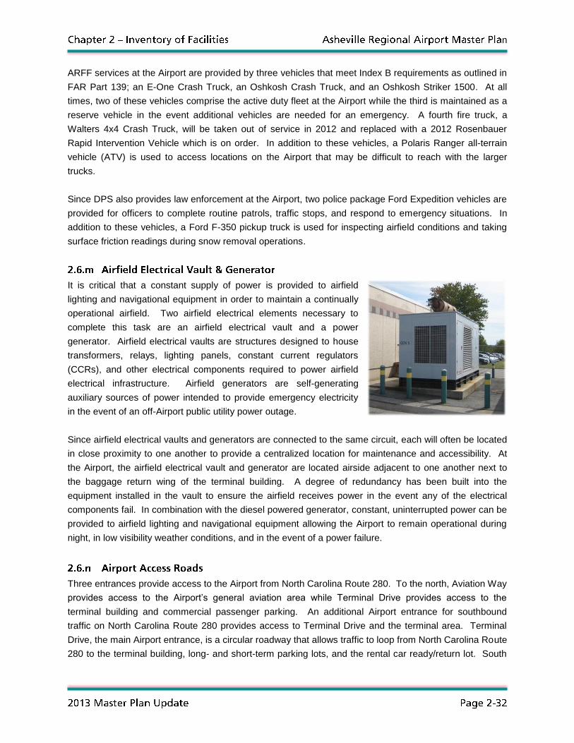
It is critical that a constant supply of power is provided to airfield
lighting and navigational equipment in order to maintain a continually
operational airfield. Two airfield electrical elements necessary to
complete this task are an airfield electrical vault and a power
generator. Airfield electrical vaults are structures designed to house
transformers, relays, lighting panels, constant current regulators
(CCRs), and other electrical components required to power airfield
electrical infrastructure. Airfield generators are self-generating
auxiliary sources of power intended to provide emergency electricity
in the event of an off-Airport public utility power outage.
Since airfield electrical vaults and generators are connected to the same circuit, each will often be located
in close proximity to one another to provide a centralized location for maintenance and accessibility. At
the Airport, the airfield electrical vault and generator are located airside adjacent to one another next to
the baggage return wing of the terminal building. A degree of redundancy has been built into the
equipment installed in the vault to ensure the airfield receives power in the event any of the electrical
components fail. In combination with the diesel powered generator, constant, uninterrupted power can be
provided to airfield lighting and navigational equipment allowing the Airport to remain operational during
night, in low visibility weather conditions, and in the event of a power failure.
Three entrances provide access to the Airport from North Carolina Route 280. To the north, Aviation Way
provides access to the Airport’s general aviation area while Terminal Drive provides access to the
terminal building and commercial passenger parking. An additional Airport entrance for southbound
traffic on North Carolina Route 280 provides access to Terminal Drive and the terminal area. Terminal
Drive, the main Airport entrance, is a circular roadway that allows traffic to loop from North Carolina Route
280 to the terminal building, long- and short-term parking lots, and the rental car ready/return lot. South

n
of the rental car ready/return lot on Terminal Drive, Rental Car Drive provides gated access to the
consolidated rental car service center.
The northern entrance to the Airport provided by Aviation Way intersects Wright Brothers Way which
provides access to the various aeronautical and non-aeronautical businesses that comprise general
aviation area of the Airport. Near Landmark Aviation, Lindbergh Lane intersects Wright Brothers Way to
provide additional access to the FBO as well as Belle Air Maintenance Facility and Hangar #30. All
Airport access roads are considered to be in good condition with recent improvements occurring on
Terminal Drive (resurfacing) and Wright Brothers Way (resurfacing and widening). Figure 2-17 illustrates
the access roads at the Airport.
Aerial Photo: Woolpert, Inc.
At the Airport, there are over 2,500 parking spaces for commercial airline passengers, terminal building
tenant employees, and rental car vehicles divided between ten different lots. The public long-term
parking lot, located adjacent to the terminal building, has the largest parking capacity with 752 available
spaces. Within the long-term lot is a designated short-term lot that provides an additional 192 public
parking spaces. An overflow lot, located south of the long-term lot, adds an additional 520 parking
spaces totaling the Airport’s public parking capacity for commercial airline passengers at 1,465 vehicles.
In addition to these lots, a cell phone waiting lot located south of the employee parking lot provides an
additional 48 spaces for public parking that are designated only for vehicles waiting to pick up arriving
passengers.
South of the terminal building near the baggage claim entrance is a rental car ready/return lot that has a
parking capacity of 107 vehicles. In combination with the consolidated rental car service center that has a
capacity of 578 vehicles, a total of 685 parking spaces at the Airport are available for rental vehicles.
Parking for employees at the Airport is available at two lots south of the rental car ready/return lot that
have a combined capacity of 327 vehicles while parking for Greater Asheville Regional Airport Authority

n
employees is available at two lots north of the terminal building that have a combined capacity of 34
vehicles. DPS and Maintenance employees park in separate lots located within the north employee
parking lot (six parking spaces) and at the Maintenance facility (18 parking spaces). Though the DPS
facility has a parking lot, all spaces are reserved for either DPS vehicles or visitors. Table 2-11
summarizes the total number of allocated parking spaces at the Airport.
Note: Parking spaces in Airport tenant lots not included in this tabulation
Source: Asheville Regional Airport
The Airport’s consolidated rental car facility, constructed in
2008, is located south of the terminal parking area on Rental
Car Drive and provides the rental car agencies a centralized
location to quickly service vehicles in between rentals. The
consolidated rental car facility is comprised of two multiple bay
vehicle service buildings and two service islands. Each
vehicle service building is equipped with service bays that
feature car washing equipment, vehicle lifts, and overhead
retractable hose reels that provide pressurized air and vehicle
fluids. Adjacent to each building is a covered service island
that contains gasoline pumps and vacuums to fuel and clean vehicles.
There are several businesses, organizations, and governmental entities that engage in both aviation and
non-aviation related activities at the Airport. Each of these entities is considered to be a tenant of the
Airport since they lease office space, buildings, ticket counters, storage areas, and/or service space from
the Authority. In the terminal building, Allegiant Air, United Airlines, Delta Air Lines, and US Airways have
ticket counters, offices, and baggage makeup areas for their airline operations. The Paradies Shops,
operators of the Blue Ridge Trading + Tavern restaurant and the gift shop lease restaurant, concession,
and storage areas in the terminal for their operations. In addition to these businesses, two governmental
n
agencies responsible for the safety and security of aviation also lease office space in the terminal
building. The Transportation Security Administration (TSA) leases offices for administrative officials and
Transportation Security Officers (TSOs) while the FAA leases office and work space for its ATC
operations.
Rental car agencies based at the Airport lease space in both the terminal building and the consolidated
rental car facility for their operations. Avis, Budget, Enterprise, Hertz, and National/Alamo lease ticket
counter and office space in the terminal to conduct business transactions while offices and storage areas
at the consolidated rental car facility are leased for service employees, supplies, and materials. Also
involved in ground transportation-related activities at the Airport is Standard Parking, which has offices in
the parking lot toll booth plaza and is responsible for the management and revenue control of the Short-
and Long-Term parking lots.
Other tenants at the Airport include the FBO operator Landmark Aviation, Belle Aircraft Maintenance, and
WNC Aviation, which conducts flight instruction and provides rental aircraft. Two other governmental
entities, the U.S. Forestry Service and the Civil Air Patrol (CAP), lease buildings at the Airport for aerial
firefighting and auxiliary services for the U.S. Air Force, respectively. Finally, Advantage West, a regional
economic development commission, leases a building near the US Airways cargo facility as its center of
operations.
In addition to the collection of data on physical infrastructure elements, information was also gathered on
the surrounding airspace, ATC, and approach/departure procedures at the Airport. Evaluation of this
information from subsequent study tasks has helped to identify the adequacy of existing airspace design
and procedures to support Airport operations for the next 20 years. Elements that comprise the makeup
of airspace surrounding the Airport are presented in the following sections.
All airspace over the United States is classified into one of six different categories by the FAA based on
criteria such as level of activity, type of ATC, and requirements for IFR and VFR flight. Special
restrictions, conditions, and operating rules apply to each classification of airspace. The following lists the
different classes of airspace and describes the operational criteria associated with each.
Class A – Class A airspace is located between the altitudes of 18,000 feet and 60,000 feet MSL and lies
over the entire United States. Aircraft operating in Class A airspace must do so under IFR and file a flight
plan with an FAA Flight Service Station (FSS). All aircraft operating in this airspace must receive
approval from ATC prior to entering and must remain in constant radio communication.
Class B – Class B airspace is located between ground level and an altitude of 10,000 feet MSL and
occurs generally around airports with high levels of air traffic. The horizontal dimension of Class B
n
airspace varies based on the specific needs of an Airport, such as the orientation of runways, surrounding
land uses, and arrival and departure procedures. Aircraft operating in this class of airspace must receive
clearance from ATC prior to entering and remain in constant radio communication.
Class C – Class C airspace is located between ground level and an altitude of 4,000 feet MSL and is
assigned around airports with a control tower, radar approach control, and have a significant number of
IFR operations. The horizontal dimension of Class C airspace varies based upon the specific needs of an
Airport but is generally two-tiered in shape with a with an inner radius of five miles around an airport from
ground level to an altitude of 1,200 feet MSL and an outer radius of ten miles from an altitude of 1,200
feet MSL to 4,000 feet MSL. Permission and constant radio communication from ATC is required for
aircraft to operate in Class C airspace.
Class D – Class D airspace is located between ground level and an altitude of 2,500 feet MSL and is
classified around airports that have an ATCT, but may not have radar approach control in the ATCT. The
horizontal dimension of Class D airspace varies based upon specific airport needs such as type of
arriving and departing aircraft, level of IFR/VFR activity, and aircraft approach and departure routes.
Aircraft must request permission from ATC and remain in constant radio communication to operate in this
airspace.
Class E – Class E airspace is all airspace from ground level to 18,000 feet MSL and from 60,000 feet
MSL to the upper operational ceiling of aircraft that is not classified as A, B, C, D, or G. While aircraft
operating under IFR are required to be in constant communication with ATC in Class E airspace, those
operating VFR are not required to contact ATC.
Class G – Class G airspace is located between ground level up to an altitude of 14,500 feet MSL, though
it is generally assigned to an altitude of 1,200 feet about ground level (AGL). This class of airspace is not
provided ATC services and can be found around large, remote areas.
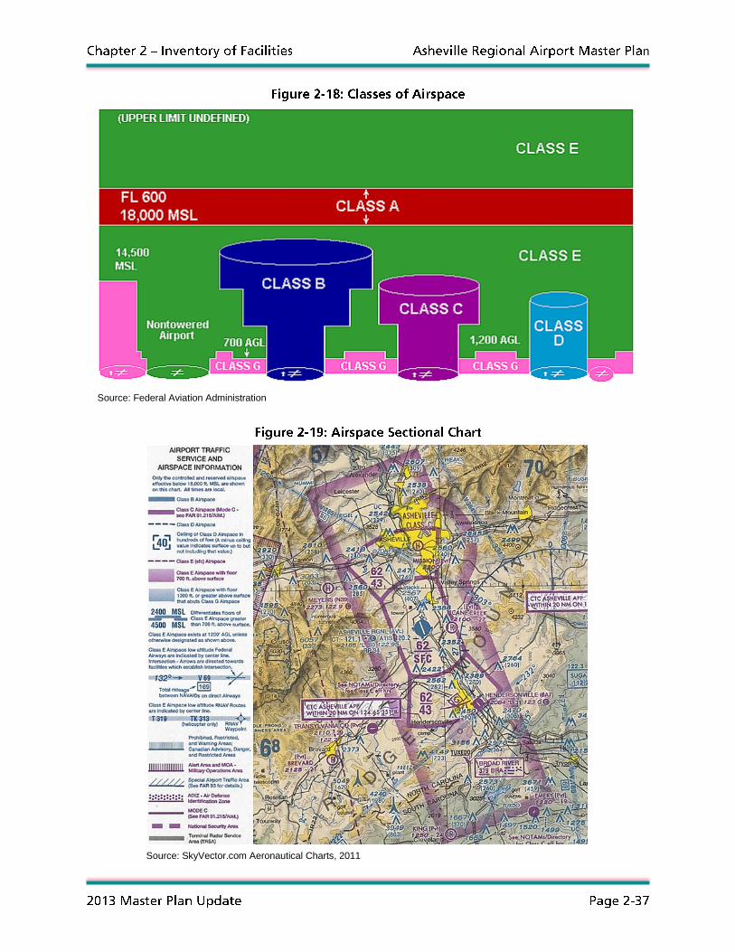
Airspace around the Airport is classified as Class C and is linear shaped based upon the arrival and
departure paths of aircraft to and from Runway 16/34. Aircraft must receive permission to enter the
airspace and be in constant radio communication with both airport control tower and radar approach air
traffic controllers. Figure 2-18 illustrates the six classifications of airspace while Figure 2-19 illustrates
the airspace around the Airport from the FAA Airspace Sectional Chart.
n
Source: Federal Aviation Administration
Source: SkyVector.com Aeronautical Charts, 2011

n
FAR Part 77 was established by the FAA to protect aircraft from obstructions when operating in proximity
to an airport through a set of design surfaces that protect airspace from the construction of towers,
buildings, and other tall objects. Through 14 Code of Federal Regulations (CFR) Part 77, a reporting
method has been established to notify the FAA of proposed construction that may be a hazard to safe air
navigation. Although the FAA will make a decision if the proposed construction will impact the safe and
efficient use of navigable airspace, the determination may not prevent someone from constructing or
altering a structure that is a hazard since the FAA does not have authority to control land use. The five
design surfaces defined in FAR Part 77 are summarized in the following sections.
Primary Surface – The primary surface is centered longitudinally on a runway centerline at the same
elevation as a runway and extends 200 feet beyond each end of a paved runway. On runways with turf
surfaces, the primary surface length is the same length as the runway. The width of this surface is:
250 feet for utility runways (designed for propeller driven aircraft of 12,500 pounds maximum
gross weight or less) having only visual approaches
500 feet for utility runways having non-precision instrument approaches
500 feet for runways other than utility having only visual approaches
500 feet for non-precision instrument runways other than utility having visibility minimums greater
than 3/4 statue mile
1,000 feet for non-precision instrument runways other than utility having a non-precision
instrument approach with visibility minimums as low as 3/4 statue mile
1,000 feet for precision instrument approach runways other than utility
Since Runway 16/34 is a precision instrument runway, its primary surface is 1,000 feet in width and
extends 200 feet beyond each runway end.
Approach Surface – The approach surface is centered on a runway centerline and extends longitudinally
upward and outward away from the primary surface at each runway end. The inner width of the surface
is the same width as the primary surface and expands uniformly to a width of:
1,250 feet for the end of a utility runway with only visual approaches
1,500 feet for the end of a runway other than utility with only visual approaches
2,000 feet for the end of a utility runway with a non-precision instrument approach
3,500 feet for the end of a non-precision instrument runway other than utility having visibility
minimums greater than 3/4 statue mile
4,000 feet for the end of a non-precision instrument runway other than utility having a non-
precision instrument approach with visibility minimums as low as 3/4 statue mile
16,000 feet for precision instrument runways
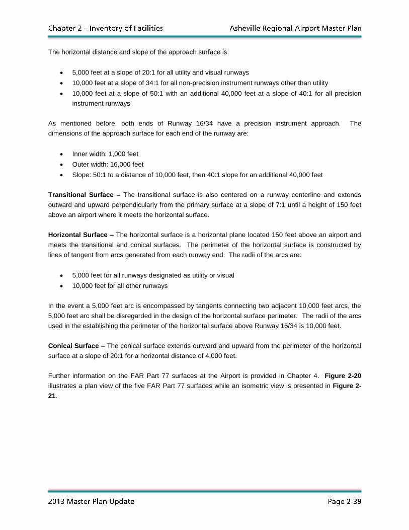
n
The horizontal distance and slope of the approach surface is:
5,000 feet at a slope of 20:1 for all utility and visual runways
10,000 feet at a slope of 34:1 for all non-precision instrument runways other than utility
10,000 feet at a slope of 50:1 with an additional 40,000 feet at a slope of 40:1 for all precision
instrument runways
As mentioned before, both ends of Runway 16/34 have a precision instrument approach. The
dimensions of the approach surface for each end of the runway are:
Inner width: 1,000 feet
Outer width: 16,000 feet
Slope: 50:1 to a distance of 10,000 feet, then 40:1 slope for an additional 40,000 feet
Transitional Surface – The transitional surface is also centered on a runway centerline and extends
outward and upward perpendicularly from the primary surface at a slope of 7:1 until a height of 150 feet
above an airport where it meets the horizontal surface.
Horizontal Surface – The horizontal surface is a horizontal plane located 150 feet above an airport and
meets the transitional and conical surfaces. The perimeter of the horizontal surface is constructed by
lines of tangent from arcs generated from each runway end. The radii of the arcs are:
5,000 feet for all runways designated as utility or visual
10,000 feet for all other runways
In the event a 5,000 feet arc is encompassed by tangents connecting two adjacent 10,000 feet arcs, the
5,000 feet arc shall be disregarded in the design of the horizontal surface perimeter. The radii of the arcs
used in the establishing the perimeter of the horizontal surface above Runway 16/34 is 10,000 feet.
Conical Surface – The conical surface extends outward and upward from the perimeter of the horizontal
surface at a slope of 20:1 for a horizontal distance of 4,000 feet.
Further information on the FAR Part 77 surfaces at the Airport is provided in Chapter 4. Figure 2-20
illustrates a plan view of the five FAR Part 77 surfaces while an isometric view is presented in Figure 2-
21.
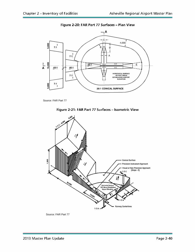
n
Source: FAR Part 77
Source: FAR Part 77
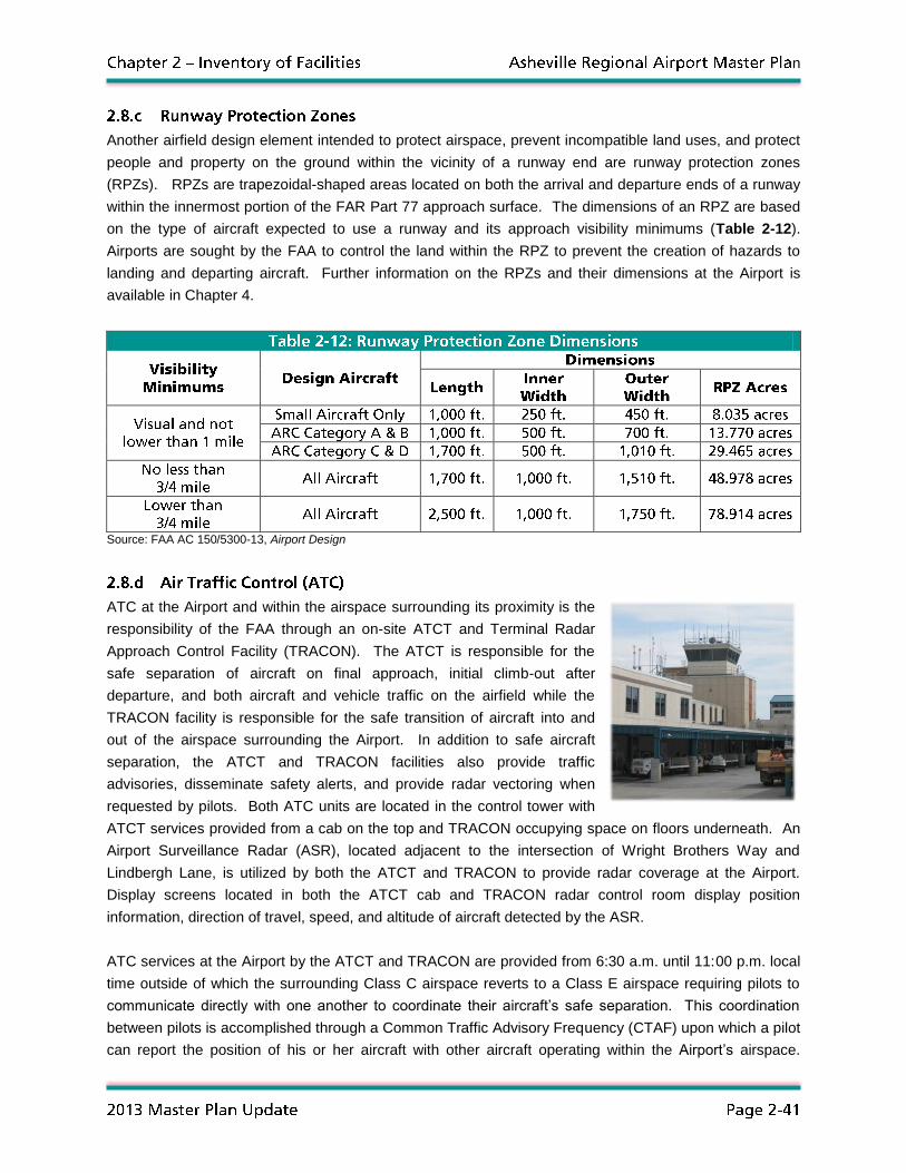
n
Another airfield design element intended to protect airspace, prevent incompatible land uses, and protect
people and property on the ground within the vicinity of a runway end are runway protection zones
(RPZs). RPZs are trapezoidal-shaped areas located on both the arrival and departure ends of a runway
within the innermost portion of the FAR Part 77 approach surface. The dimensions of an RPZ are based
on the type of aircraft expected to use a runway and its approach visibility minimums (Table 2-12).
Airports are sought by the FAA to control the land within the RPZ to prevent the creation of hazards to
landing and departing aircraft. Further information on the RPZs and their dimensions at the Airport is
available in Chapter 4.
Source: FAA AC 150/5300-13, Airport Design
ATC at the Airport and within the airspace surrounding its proximity is the
responsibility of the FAA through an on-site ATCT and Terminal Radar
Approach Control Facility (TRACON). The ATCT is responsible for the
safe separation of aircraft on final approach, initial climb-out after
departure, and both aircraft and vehicle traffic on the airfield while the
TRACON facility is responsible for the safe transition of aircraft into and
out of the airspace surrounding the Airport. In addition to safe aircraft
separation, the ATCT and TRACON facilities also provide traffic
advisories, disseminate safety alerts, and provide radar vectoring when
requested by pilots. Both ATC units are located in the control tower with
ATCT services provided from a cab on the top and TRACON occupying space on floors underneath. An
Airport Surveillance Radar (ASR), located adjacent to the intersection of Wright Brothers Way and
Lindbergh Lane, is utilized by both the ATCT and TRACON to provide radar coverage at the Airport.
Display screens located in both the ATCT cab and TRACON radar control room display position
information, direction of travel, speed, and altitude of aircraft detected by the ASR.
ATC services at the Airport by the ATCT and TRACON are provided from 6:30 a.m. until 11:00 p.m. local
time outside of which the surrounding Class C airspace reverts to a Class E airspace requiring pilots to
communicate directly with one another to coordinate their aircraft’s safe separation. This coordination
between pilots is accomplished through a Common Traffic Advisory Frequency (CTAF) upon which a pilot
can report the position of his or her aircraft with other aircraft operating within the Airport’s airspace.

n
Basic radar services during the closure of the ATCT and TRACON are provided by the Atlanta Air Route
Traffic Control Center (Atlanta ARTCC) located in Atlanta, Georgia, which is responsible for the safe
separation of aircraft in airspace surrounding the Airport.
Aircraft separation services provided by the ATCT and TRACON are divided into operational disciplines
based on the air traffic separation needs for each phase of flight. The following summarizes the
operational disciplines offered by ATC at the Airport:
Ground Control – Ground control is a position within the ATCT that is responsible for the movement of
aircraft and vehicles on runways, taxiways, and aprons located within the aircraft movement area. In
addition to providing taxiing instructions to aircraft and overseeing the safe passage of vehicles, ground
control is also responsible for personnel and equipment operating within the safety area of runways and
taxiways. All aircraft, vehicles, personnel, and equipment are required to:
Request permission from ground control to enter the movement area
Remain in constant radio communication with ground control while within the movement area
Notify ground control upon exiting the movement area
Tower – The tower controller position is responsible for the safe separation of arriving and departing
aircraft from the Airport. In addition to providing landing and takeoff clearances, the tower controller also
is responsible for the separation of aircraft that transition to and from airspace controlled by TRACON.
Approach/Departure Control – Approach/departure controllers are positions within TRACON that are
responsible for the separation of arriving, departing, and transient aircraft within 20 nautical miles of the
Airport. Depending on the traffic volume and available staffing, the approach and departure control
positions may be combined into the responsibility of a single controller.
Table 2-13 summarizes the communication frequencies utilized by ATC controllers at the Airport. In
addition to ground control, tower, and approach/departure control, frequencies are also assigned for the
continual broadcast of weather observations and Airport condition information through the Automatic
Terminal Information Service (ATIS), emergencies, and for non-ATC related radio traffic through the
universal communications frequency (UNICOM).
Source: FAA Airport/Facility Directory
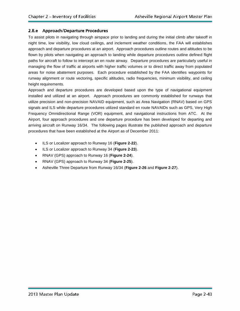
n
To assist pilots in navigating through airspace prior to landing and during the initial climb after takeoff in
night time, low visibility, low cloud ceilings, and inclement weather conditions, the FAA will establishes
approach and departure procedures at an airport. Approach procedures outline routes and altitudes to be
flown by pilots when navigating an approach to landing while departure procedures outline defined flight
paths for aircraft to follow to intercept an en route airway. Departure procedures are particularly useful in
managing the flow of traffic at airports with higher traffic volumes or to direct traffic away from populated
areas for noise abatement purposes. Each procedure established by the FAA identifies waypoints for
runway alignment or route vectoring, specific altitudes, radio frequencies, minimum visibility, and ceiling
height requirements.
Approach and departure procedures are developed based upon the type of navigational equipment
installed and utilized at an airport. Approach procedures are commonly established for runways that
utilize precision and non-precision NAVAID equipment, such as Area Navigation (RNAV) based on GPS
signals and ILS while departure procedures utilized standard en route NAVAIDs such as GPS, Very High
Frequency Omnidirectional Range (VOR) equipment, and navigational instructions from ATC. At the
Airport, four approach procedures and one departure procedure has been developed for departing and
arriving aircraft on Runway 16/34. The following pages illustrate the published approach and departure
procedures that have been established at the Airport as of December 2011:
ILS or Localizer approach to Runway 16 (Figure 2-22).
ILS or Localizer approach to Runway 34 (Figure 2-23).
RNAV (GPS) approach to Runway 16 (Figure 2-24).
RNAV (GPS) approach to Runway 34 (Figure 2-25).
Asheville Three Departure from Runway 16/34 (Figure 2-26 and Figure 2-27).

n
Source: Federal Aviation Administration

n
Source: Federal Aviation Administration

n
Source: Federal Aviation Administration

n
Source: Federal Aviation Administration

n
Source: Federal Aviation Administration

n
Source: Federal Aviation Administration

n
Information collected during the inventory effort of the
master planning process provides a method to
evaluate the conditions of existing Airport facilities and
provide a baseline to measure how well current
infrastructure will be able to accommodate future
aviation demand. Through a review of the inventory
information presented in this Chapter, subsequent
study tasks can be conducted to determine what
improvements will be necessary at the Airport to meet
the air transportation requirements of Western North
Carolina over the next 20 years. In comparison with
future aviation demand projections and demand/capacity analyses, alternatives can be developed to
identify a plan on how the Airport will address the required improvements. Ashville Regional Airport has
continually evolved over its 50-year history to meet the demand of its users, and this study effort will help
direct the prospective growth and expansion of existing Airport facilities to meet future aviation needs.


![Welcome [s3.eu-central-1.amazonaws.com]...bb bb bb bb bb # # # # # b b bb bb bb bb bb bb bb bb 4 4 4 4 4 4 4 4 4 4 4 4 4 4 4 4 4 4 4 4 4 4 4 4 4 4 4 4 4 4 4 4 4 4 4 4 4 4 4 4 44 4](https://img.pdfslide.us/doc/110x75/5e9f761d9d1aa23b1a09f03e/welcome-s3eu-central-1-bb-bb-bb-bb-bb-b-b-bb-bb-bb-bb-bb-bb-bb.jpg)
![Chemical Resistance Chart for Metal - ARC Industrial … Chloride [CH3CH2Cl] 4 4 4 4 3 4 4 4 4 4 4 4 4 4 4 4 4 2 4 ethylene Dichloride [ClCH2CH2Cl] 4 4 4 4 3 4 4 4 4 4 4 4 4 4 4 4](https://img.pdfslide.us/doc/110x75/5ac7280c7f8b9a220b8e82c8/chemical-resistance-chart-for-metal-arc-industrial-chloride-ch3ch2cl-4-4.jpg)


![Finale 2005a - [Untitled1]h).pdf · 2014-02-18 · 4 4 4 4 4 4 4 4 4 4 4 4 4 4 4 4 4 4 4 4 4 4 4 4 4 4 4 4 4 4 4 4 4 4 4 4 4 4 4 4 4 4 4 4 4 4 4 4 4 4 Picc. Flutes Oboe Bassoon Bb](https://img.pdfslide.us/doc/110x75/5b737b707f8b9a95348e2e6f/finale-2005a-untitled1-hpdf-2014-02-18-4-4-4-4-4-4-4-4-4-4-4-4-4-4.jpg)