Embed Size (px)
Citation preview
(4) Equate 0 encIµ with
to obtain d⋅∫ B s B0
2IBr
µπ
= 00
NIB nIl
µ µ= = 0
2NIBr
µπ
=
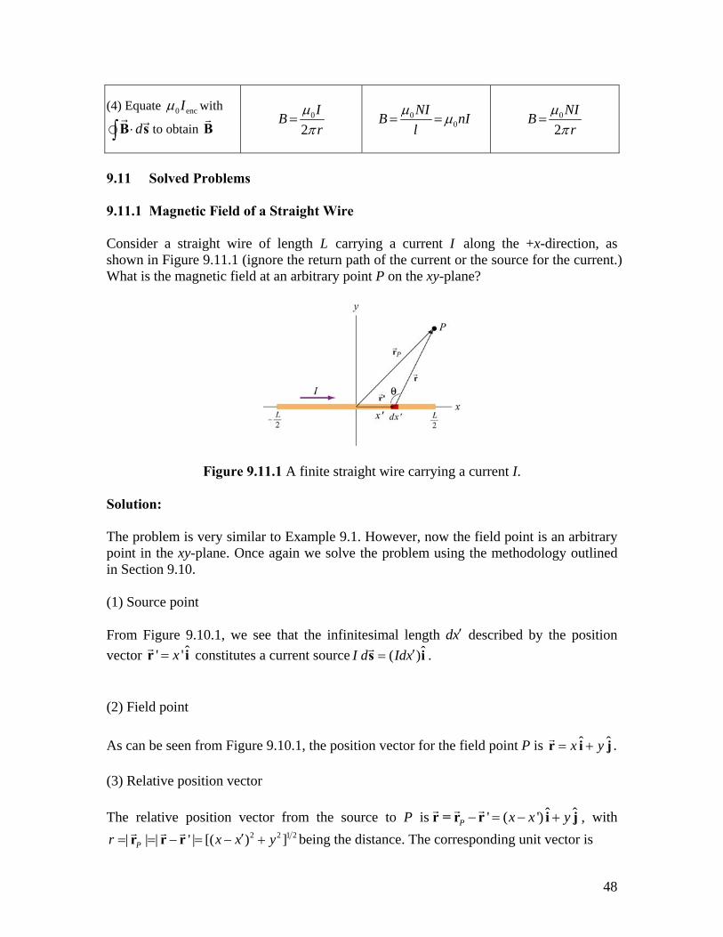
9.11 Solved Problems 9.11.1 Magnetic Field of a Straight Wire Consider a straight wire of length L carrying a current I along the +x-direction, as shown in Figure 9.11.1 (ignore the return path of the current or the source for the current.) What is the magnetic field at an arbitrary point P on the xy-plane?
Figure 9.11.1 A finite straight wire carrying a current I. Solution: The problem is very similar to Example 9.1. However, now the field point is an arbitrary point in the xy-plane. Once again we solve the problem using the methodology outlined in Section 9.10. (1) Source point From Figure 9.10.1, we see that the infinitesimal length dx′ described by the position vector ˆ' 'x=r i constitutes a current source ˆ( )I d Idx′=s i . (2) Field point As can be seen from Figure 9.10.1, the position vector for the field point P is ˆ ˆx y= +r i j . (3) Relative position vector The relative position vector from the source to P is ˆ' ( ')P
ˆx x y− = − +r = r r i j , with 2 2 1| | | ' | [( ) ]Pr x x′= = − = − +r r r 2y being the distance. The corresponding unit vector is
48
2 2 1
ˆ ˆ' ( )ˆ| ' | [( ) ]
P
P2
x x yr x x
′− − += = =
′− − +r rr irr r y
j
(4) Simplifying the cross product The cross product d can be simplified as ×s r ˆ ˆ ˆ ˆ( ' ) [( ') ] 'dx x x y y dx× − + =i i j k where we have used ˆ ˆ and ˆ ˆ× =i i 0 ˆ× =i j k . (5) Writing down dB Using the Biot-Savart law, the infinitesimal contribution due to Id s is
0 0 02 3 2 2
ˆ ˆ4 4 4 [( )
I I Id d y dxdr r x x y 3 2]
µ µ µπ π π
′× ×= = =
′− +s r s rB k (9.11.1)
Thus, we see that the direction of the magnetic field is in the ˆ+k direction. (6) Carrying out the integration to obtain B The total magnetic field at P can then be obtained by integrating over the entire length of the wire:
/ 2/ 2 0 0
2 2 3 2 2 2/ 2wire / 2
02 2 2 2
( )ˆ ˆ4 [( ) ] 4 ( )
( / 2) ( / 2) ˆ4 ( / 2) ( / 2)
LL
LL
Iy dx I x xdx x y y x x y
I x L x Ly x L y x L y
µ µπ π
µπ
−−
′ ′−= = = −
′− + ′− +
⎡ ⎤− += − −⎢ ⎥
⎢ − + + + ⎥⎣ ⎦
∫ ∫B B k
k
k
(9.11.2)
Let’s consider the following limits: (i) 0x = In this case, the field point P is at ( , ) (0, )x y y= on the y axis. The magnetic field becomes
49
0 02 2 2 2 2 2
/ 2 / 2 / 2ˆ ˆ cos4 2( / 2) ( / 2) ( / 2)
I IL L Ly yL y L y L y
µ µ 0 ˆ2
Iy
µ θπ π
⎡ ⎤− += − − = =⎢ ⎥
⎢ − + + + ⎥ +⎣ ⎦B k
πk k
(9.11.3) in agreement with Eq. (9.1.6). (ii) Infinite length limit Consider the limit where ,L x y . This gives back the expected infinite-length result:
0 / 2 / 2 ˆ4 / 2 / 2 2
0 ˆI IL Ly L L y
µπ π
− +⎡ ⎤= − − =⎢ ⎥⎣ ⎦B µk k (9.11.4)
If we use cylindrical coordinates with the wire pointing along the +z-axis then the magnetic field is given by the expression
0 ˆ2
Ir
µπ
=B φ (9.11.5)
where is the tangential unit vector and the field point P is a distance r away from the wire.
φ̂
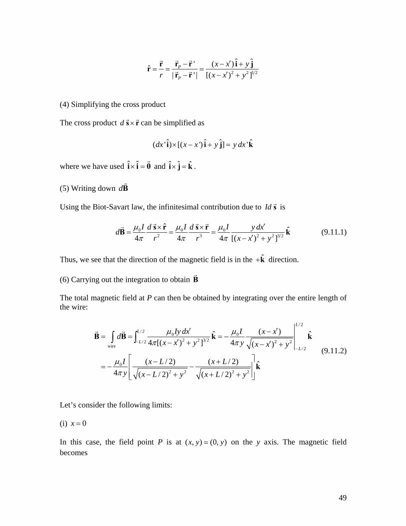
9.11.2 Current-Carrying Arc Consider the current-carrying loop formed of radial lines and segments of circles whose centers are at point P as shown below. Find the magnetic field B at P.
Figure 9.11.2 Current-carrying arc Solution: According to the Biot-Savart law, the magnitude of the magnetic field due to a differential current-carrying element I d s is given by
50
0 0 02 2
ˆ ' '4 4 4
dI I r ddB dr r
µ µ µθ Ir
θπ π π
×= = =
s r (9.11.6)
For the outer arc, we have
0outer 0
'4 4
0I IB db b
θµ µ θθπ π
= =∫ (9.11.7)
The direction of is determined by the cross productouterB ˆd ×s r which points out of the page. Similarly, for the inner arc, we have
0inner 0
'4 4
0I IB da a
θµ µ θθπ π
= =∫ (9.11.8)
For , points into the page. Thus, the total magnitude of magnetic field is innerB ˆd ×s r
0inner outer
1 1 (into page)4
Ia b
µ θπ
⎛ ⎞= = −⎜ ⎟⎝ ⎠
B B + B (9.11.9)
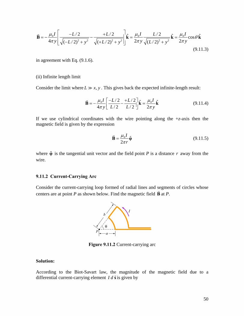
9.11.3 Rectangular Current Loop
Determine the magnetic field (in terms of I, a and b) at the origin O due to the current loop shown in Figure 9.11.3
Figure 9.11.3 Rectangular current loop
51
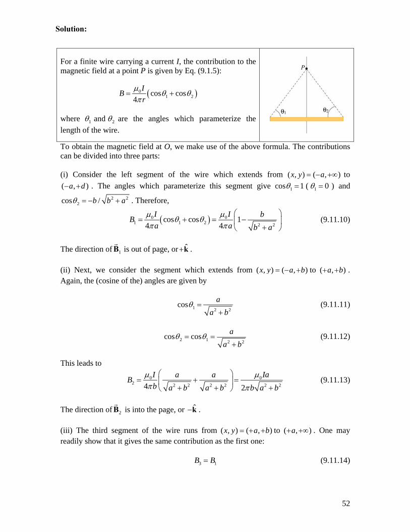
For a finite wire carrying a current I, the contribution to the magnetic field at a point P is given by Eq. (9.1.5):
( )01 2cos cos
4IBr
µ θ θπ
= +
where 1 and 2θ θ are the angles which parameterize the length of the wire.
To obtain the magnetic field at O, we make use of the above formula. The contributions can be divided into three parts: (i) Consider the left segment of the wire which extends from ( , to
. The angles which parameterize this segment give co) ( , )x y a= − +∞
( , )a d− + 1s 1θ = ( 1 0θ = ) and 2
2cos /b b aθ = − + 2 . Therefore,
( )0 01 1 2 2 2
cos cos 14 4
I I bBa a b a
µ µθ θπ π
⎛ ⎞= + = −⎜
+⎝ ⎠⎟ (9.11.10)
The direction of is out of page, or1B ˆ+k . (ii) Next, we consider the segment which extends from ( , ) ( , )x y a b= − + to . Again, the (cosine of the) angles are given by
( , )a b+ +
1 2 2cos a
a bθ =
+ (9.11.11)
2 1 2 2cos cos a
a bθ θ= =
+ (9.11.12)
This leads to
02 2 2 2 2 2 24 2
I a aBb a b a b b a b
µ µπ π
⎛ ⎞= + =⎜ ⎟ 0Ia
+ + +⎝ ⎠ (9.11.13)
The direction of is into the page, or 2B ˆ−k . (iii) The third segment of the wire runs from ( , ) ( , )x y a b= + + to ( , )a+ +∞ . One may readily show that it gives the same contribution as the first one: 3 1B B= (9.11.14)
52
Solution:
The direction of is again out of page, or 3B ˆ+k . The magnetic field is
( )
0 01 2 3 1 2 2 2 2 2
2 2 2 202 2
ˆ ˆ2 12 2
ˆ2
I Iba a b b a b
I b a b b aab a b
µ µπ π
µ
π
⎛ ⎞= + + = + = − −⎜ ⎟
+⎝ ⎠
= + − −+
B B B B B B k k
k
a+ (9.11.15)
Note that in the limit , the horizontal segment is absent, and the two semi-infinite wires carrying currents in the opposite direction overlap each other and their contributions completely cancel. Thus, the magnetic field vanishes in this limit.
0a →
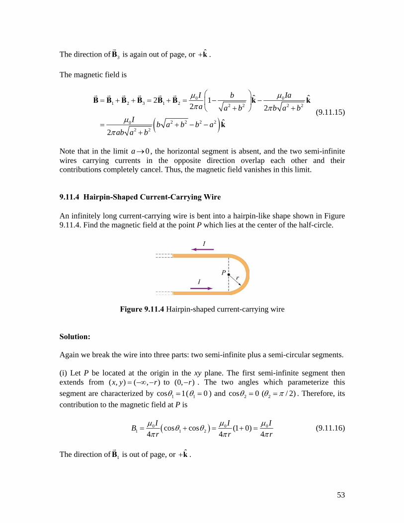
9.11.4 Hairpin-Shaped Current-Carrying Wire An infinitely long current-carrying wire is bent into a hairpin-like shape shown in Figure 9.11.4. Find the magnetic field at the point P which lies at the center of the half-circle.
Figure 9.11.4 Hairpin-shaped current-carrying wire Solution: Again we break the wire into three parts: two semi-infinite plus a semi-circular segments. (i) Let P be located at the origin in the xy plane. The first semi-infinite segment then extends from ( , ) ( , )x y r= −∞ − to (0, )r− . The two angles which parameterize this segment are characterized by 1cos 1θ = ( 1 0θ = ) and 2 2cos 0 ( / 2)θ θ π= = . Therefore, its contribution to the magnetic field at P is
( )0 01 1 2cos cos (1 0)
4 40
4I IBr r
Ir
µ µθ θ µπ π π
= + = + = (9.11.16)
The direction of is out of page, or 1B ˆ+k .
53
(ii) For the semi-circular arc of radius r, we make use of the Biot-Savart law:
02
ˆ4
I dr
µπ
×= ∫
s rB (9.11.17)
and obtain
02 204 4
0I IrdBr r
πµ µθπ
= =∫ (9.11.18)
The direction of is out of page, or2B ˆ+k . (iii) The third segment of the wire runs from ( , ) (0, )x y r= + to ( , r)−∞ + . One may readily show that it gives the same contribution as the first one:
03 1 4
IB Br
µπ
= = (9.11.19)
The direction of is again out of page, or 3B ˆ+k . The total magnitude of the magnetic field is
0 0 01 2 3 1 2
ˆ ˆ2 (2 4 4
I I Ir r r
ˆ2 )µ µ µ ππ π
= + + = + = + = +B B B B B B k k k (9.11.20)
Notice that the contribution from the two semi-infinite wires is equal to that due to an infinite wire:
01 3 1
ˆ22
Ir
µπ
+ = =B B B k (9.11.21)
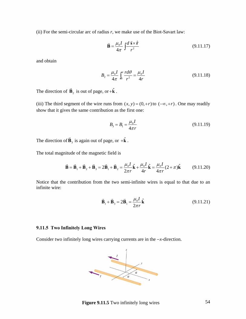
9.11.5 Two Infinitely Long Wires Consider two infinitely long wires carrying currents are in the −x-direction.
54Figure 9.11.5 Two infinitely long wires
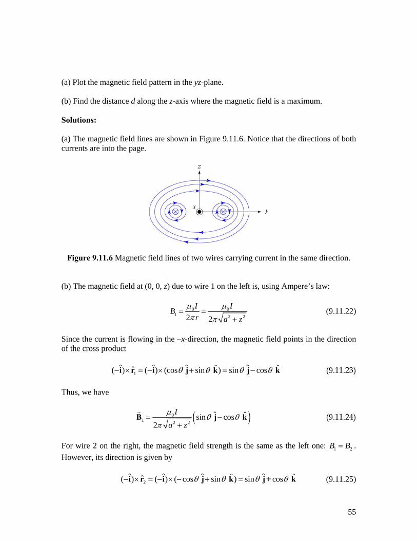
(a) Plot the magnetic field pattern in the yz-plane. (b) Find the distance d along the z-axis where the magnetic field is a maximum. Solutions: (a) The magnetic field lines are shown in Figure 9.11.6. Notice that the directions of both currents are into the page.
Figure 9.11.6 Magnetic field lines of two wires carrying current in the same direction. (b) The magnetic field at (0, 0, z) due to wire 1 on the left is, using Ampere’s law:
0 01 2 22 2
I IBr a z
µ µπ π
= =+
(9.11.22)
Since the current is flowing in the –x-direction, the magnetic field points in the direction of the cross product 1
ˆ ˆ ˆ ˆˆˆ( ) ( ) (cos sin ) sin cos ˆθ θ θ− × = − × + = −i r i j k j kθ (9.11.23) Thus, we have
( )01 2 2
ˆ ˆsin cos 2
Ia zµ θ θ
π= −
+B j k (9.11.24)
For wire 2 on the right, the magnetic field strength is the same as the left one: 1 2B B= . However, its direction is given by 2
ˆ ˆ ˆ ˆˆˆ( ) ( ) ( cos sin ) sin cos ˆθ θ θ− × = − × − + =i r i j k j+ kθ (9.11.25)
55
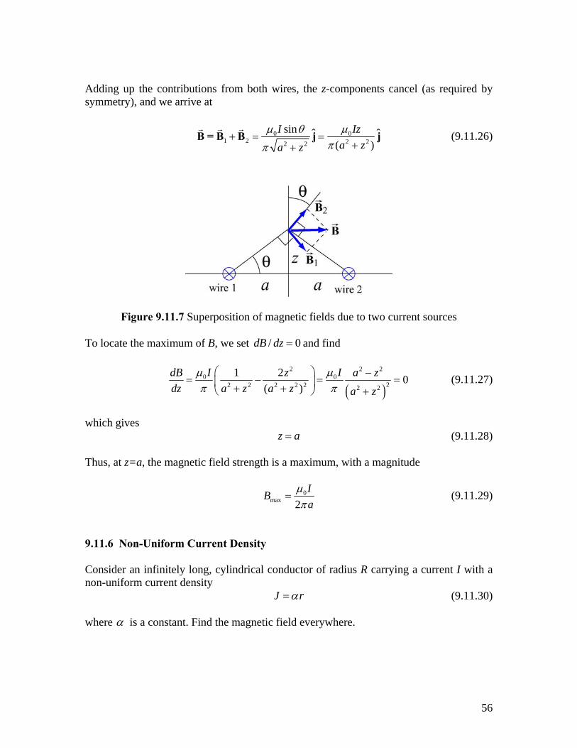
Adding up the contributions from both wires, the z-components cancel (as required by symmetry), and we arrive at
01 2 2 22 2
sin ˆ( )
Ia za z
0 ˆIzµ θ µππ
+ = =++
B = B B j j (9.11.26)
Figure 9.11.7 Superposition of magnetic fields due to two current sources To locate the maximum of B, we set /dB dz 0= and find
( )
2 20 0
22 2 2 2 2 2 2
1 2 0( )
I IdB z a zdz a z a z a z
µ µπ π
⎛ ⎞ −= − =⎜ ⎟+ +⎝ ⎠ +
2
= (9.11.27)
which gives z a= (9.11.28) Thus, at z=a, the magnetic field strength is a maximum, with a magnitude
0max 2
IBa
µπ
= (9.11.29)
9.11.6 Non-Uniform Current Density Consider an infinitely long, cylindrical conductor of radius R carrying a current I with a non-uniform current density J rα= (9.11.30) where α is a constant. Find the magnetic field everywhere.
56
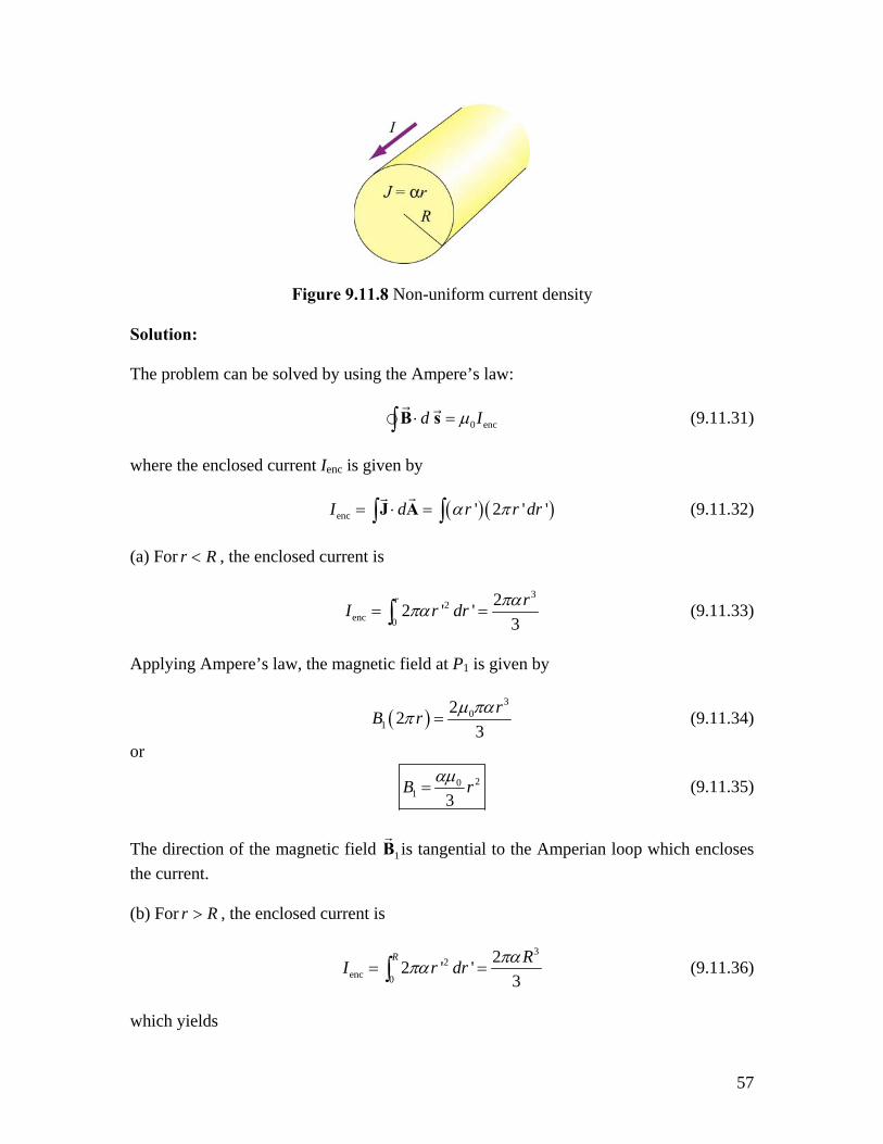
Figure 9.11.8 Non-uniform current density Solution: The problem can be solved by using the Ampere’s law: 0 encd Iµ⋅ =∫ B s (9.11.31) where the enclosed current Ienc is given by ( )( )enc ' 2 ' 'I d r r dα π= ⋅ = r∫ ∫J A (9.11.32) (a) For r , the enclosed current is R<
3
2enc 0
22 ' '3
r rI r dr παπα= =∫ (9.11.33)
Applying Ampere’s law, the magnetic field at P1 is given by
( )3
01
223
rB r µ παπ = (9.11.34)
or
201 3
B rαµ= (9.11.35)
The direction of the magnetic field 1B is tangential to the Amperian loop which encloses the current. (b) For , the enclosed current is r R>
3
2enc 0
22 ' '3
R RI r dr παπα= =∫ (9.11.36)
which yields
57
( )3
02
223
RB r µ παπ = (9.11.37)
Thus, the magnetic field at a point P2 outside the conductor is
3
02 3
RBr
αµ= (9.11.38)
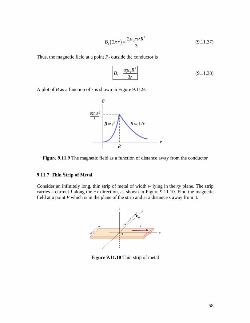
A plot of B as a function of r is shown in Figure 9.11.9:
Figure 9.11.9 The magnetic field as a function of distance away from the conductor 9.11.7 Thin Strip of Metal Consider an infinitely long, thin strip of metal of width w lying in the xy plane. The strip carries a current I along the +x-direction, as shown in Figure 9.11.10. Find the magnetic field at a point P which is in the plane of the strip and at a distance s away from it.
Figure 9.11.10 Thin strip of metal
58
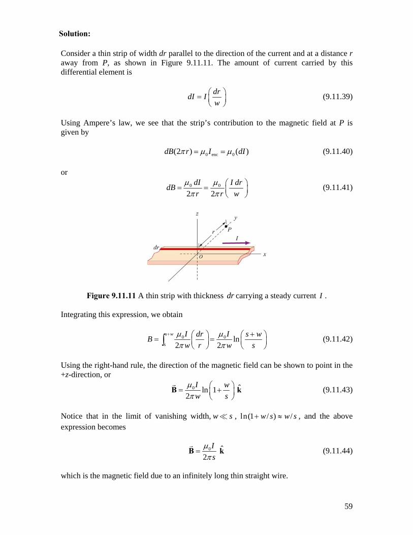
Consider a thin strip of width dr parallel to the direction of the current and at a distance r away from P, as shown in Figure 9.11.11. The amount of current carried by this differential element is
drdI Iw
⎛= ⎜⎝ ⎠
⎞⎟ (9.11.39)
Using Ampere’s law, we see that the strip’s contribution to the magnetic field at P is given by 0 enc 0(2 ) ( )dB r I dIπ µ µ= = (9.11.40) or
0 0
2 2dI I drdBr r w
µ µπ π
⎛= = ⎜⎝ ⎠
⎞⎟ (9.11.41)
Figure 9.11.11 A thin strip with thickness carrying a steady current dr I . Integrating this expression, we obtain
0 0 ln2 2
s w
s
I Idr s wBw r w s
µ µπ π
+ +⎛ ⎞ ⎛= =⎜ ⎟ ⎜⎝ ⎠ ⎝∫ ⎞
⎟⎠
(9.11.42)
Using the right-hand rule, the direction of the magnetic field can be shown to point in the +z-direction, or
0 ˆln 1 2
I ww s
µπ
⎛ ⎞= +⎜ ⎟⎝ ⎠
B k (9.11.43)
Notice that in the limit of vanishing width, , w s ln(1 / ) /w s w s+ ≈ , and the above expression becomes
0 ˆ2
Is
µπ
=B k (9.11.44)
which is the magnetic field due to an infinitely long thin straight wire.
59
Solution:
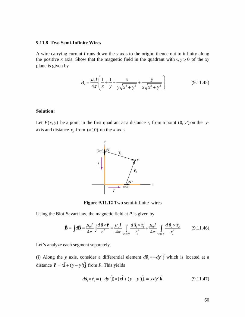
9.11.8 Two Semi-Infinite Wires A wire carrying current I runs down the y axis to the origin, thence out to infinity along the positive x axis. Show that the magnetic field in the quadrant with of the xy plane is given by
,x y > 0
02 2 2 2
1 14z
I x yBx y y x y x x y
µπ
⎛ ⎞⎜= + + +⎜ + +⎝ ⎠
⎟⎟
(9.11.45)
Solution: Let ( , )P x y be a point in the first quadrant at a distance from a point (01r , ')y on the y-axis and distance from on the x-axis. 2r ( ',0)x
Figure 9.11.12 Two semi-infinite wires Using the Biot-Savart law, the magnetic field at P is given by
0 0 01 1 2 22 2
1 2wire wire
ˆ ˆˆ4 4 4y x
I I Id dddr r 2r
µ µ µπ π π
× ××= = = +∫ ∫ ∫ ∫
s r s rs rB B (9.11.46)
Let’s analyze each segment separately. (i) Along the y axis, consider a differential element 1
ˆ'd dy= −s j which is located at a
distance 1ˆ ( ' ˆ)x y y= + −r i j
y
from P. This yields (9.11.47) 1 1
ˆ ˆ ˆ ˆ( ' ) [ ( ') ] 'd dy x y y x d× = − × + − =s r j i j k
60
(ii) Similarly, along the x-axis, we have 2
ˆ'd dx=s i and 2ˆ( ') ˆx x y= − +r i j which gives
2 2
ˆ'd y d× =s r kx (9.11.48) Thus, we see that the magnetic field at P points in the +z-direction. Using the above
results and 2 21 ( ')r x y y= + − and ( )2 2
2r x x′= − + y , we obtain
0 02 2 3/ 2 2 20 0
'4 [ ( ') ] 4 [ ( ') ]z
I Ix dy y dxBx y y y x x 3/ 2
'µ µπ π
∞ ∞= +
+ − + −∫ ∫ (9.11.49)
The integrals can be readily evaluated using
2 2 3/ 2 2 20
1[ ( ) ]
b ds ab a s b b a b
∞= +
+ − +∫ (9.11.50)
The final expression for the magnetic field is given by
02 2 2 2
1 1 ˆ4
I y xx yx x y y x y
µπ
⎡ ⎤= + + +⎢
⎢ + +⎣ ⎦B k⎥
⎥ (9.11.51)
We may show that the result is consistent with Eq. (9.1.5) 9.12 Conceptual Questions 1. Compare and contrast Biot-Savart law in magnetostatics with Coulomb’s law in electrostatics. 2. If a current is passed through a spring, does the spring stretch or compress? Explain. 3. How is the path of the integration of d⋅∫ B s chosen when applying Ampere’s law? 4. Two concentric, coplanar circular loops of different diameters carry steady currents in the same direction. Do the loops attract or repel each other? Explain. 5. Suppose three infinitely long parallel wires are arranged in such a way that when looking at the cross section, they are at the corners of an equilateral triangle. Can currents be arranged (combination of flowing in or out of the page) so that all three wires (a) attract, and (b) repel each other? Explain.
61
9.13 Additional Problems 9.13.1 Application of Ampere's Law The simplest possible application of Ampere's law allows us to calculate the magnetic field in the vicinity of a single infinitely long wire. Adding more wires with differing currents will check your understanding of Ampere's law. (a) Calculate with Ampere's law the magnetic field, | | ( )B r=B , as a function of distance r from the wire, in the vicinity of an infinitely long straight wire that carries current I. Show with a sketch the integration path you choose and state explicitly how you use symmetry. What is the field at a distance of 10 mm from the wire if the current is 10 A?
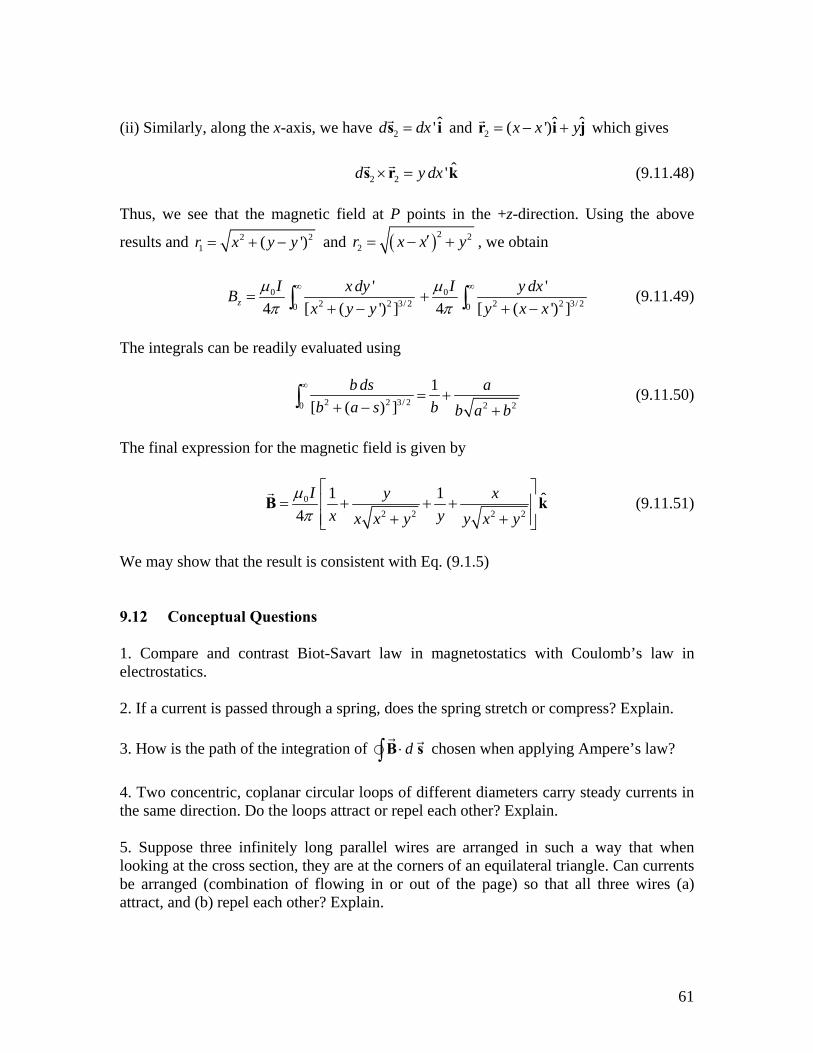
(b) Eight parallel wires cut the page perpendicularly at the points shown. A wire labeled with the integer k (k = 1, 2, ... , 8) bears the current 2k times 0I (i.e., 02kI k I= ). For those with k = 1 to 4, the current flows up out of the page; for the rest, the current flows down into the page. Evaluate d⋅∫ B s along the closed path (see figure) in the direction indicated by the arrowhead. (Watch your signs!)
Figure 9.13.1 Amperian loop
(c) Can you use a single application of Ampere's Law to find the field at a point in the vicinity of the 8 wires? Why? How would you proceed to find the field at an arbitrary point P? 9.13.2 Magnetic Field of a Current Distribution from Ampere's Law Consider the cylindrical conductor with a hollow center and copper walls of thickness
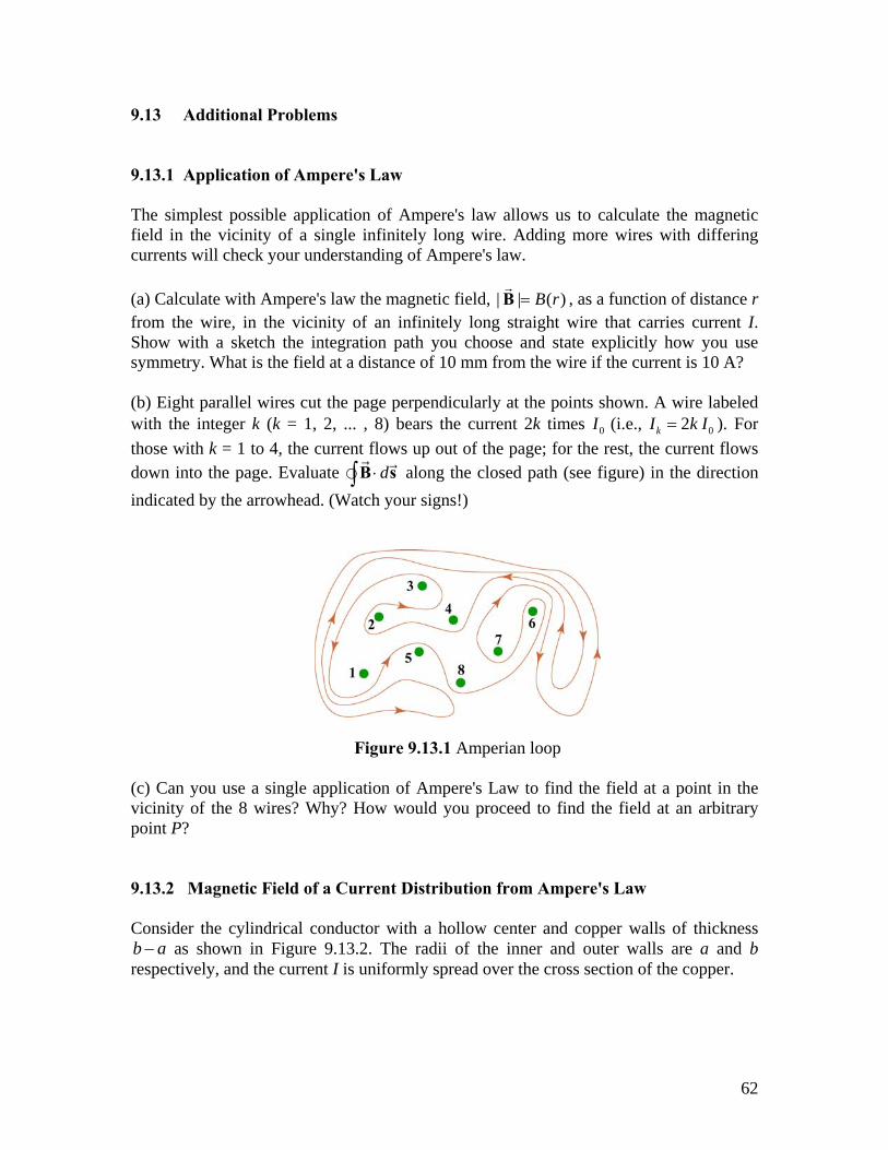
as shown in Figure 9.13.2. The radii of the inner and outer walls are a and b respectively, and the current I is uniformly spread over the cross section of the copper. b a−
62
(a) Calculate the magnitude of the magnetic field in the region outside the conductor, . (Hint: consider the entire conductor to be a single thin wire, construct an
Amperian loop, and apply Ampere's Law.) What is the direction ofr b>
B ?
Figure 9.13.2 Hollow cylinder carrying a steady current I.
(b) Calculate the magnetic field inside the inner radius, r < a. What is the direction of B ? (c) Calculate the magnetic field within the inner conductor, a < r < b. What is the direction of ? B (d) Plot the behavior of the magnitude of the magnetic field B(r) from r = 0 to . Is B(r) continuous at r = a and r = b? What about its slope?
4r = b
(e) Now suppose that a very thin wire running down the center of the conductor carries the same current I in the opposite direction. Can you plot, roughly, the variation of B(r) without another detailed calculation? (Hint: remember that the vectors d from different current elements can be added to obtain the total vector magnetic field.)
B
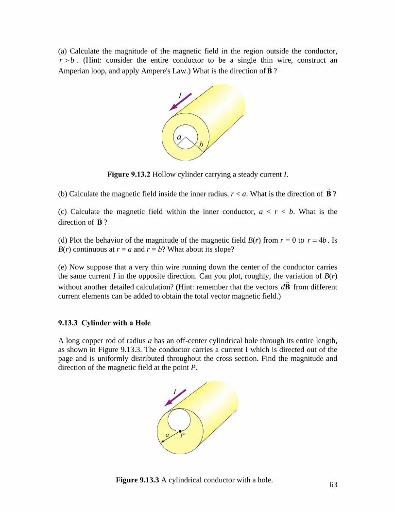
9.13.3 Cylinder with a Hole A long copper rod of radius a has an off-center cylindrical hole through its entire length, as shown in Figure 9.13.3. The conductor carries a current I which is directed out of the page and is uniformly distributed throughout the cross section. Find the magnitude and direction of the magnetic field at the point P.
63Figure 9.13.3 A cylindrical conductor with a hole.
9.13.4 The Magnetic Field Through a Solenoid A solenoid has 200 closely spaced turns so that, for most of its length, it may be considered to be an ideal solenoid. It has a length of 0.25 m, a diameter of 0.1 m, and carries a current of 0.30 A. (a) Sketch the solenoid, showing clearly the rotation direction of the windings, the current direction, and the magnetic field lines (inside and outside) with arrows to show their direction. What is the dominant direction of the magnetic field inside the solenoid? (b) Find the magnitude of the magnetic field inside the solenoid by constructing an Amperian loop and applying Ampere's law. (c) Does the magnetic field have a component in the direction of the wire in the loops making up the solenoid? If so, calculate its magnitude both inside and outside the solenoid, at radii 30 mm and 60 mm respectively, and show the directions on your sketch. 9.13.5 Rotating Disk A circular disk of radius R with uniform charge density σ rotates with an angular speed ω . Show that the magnetic field at the center of the disk is
012
B Rµ σω=
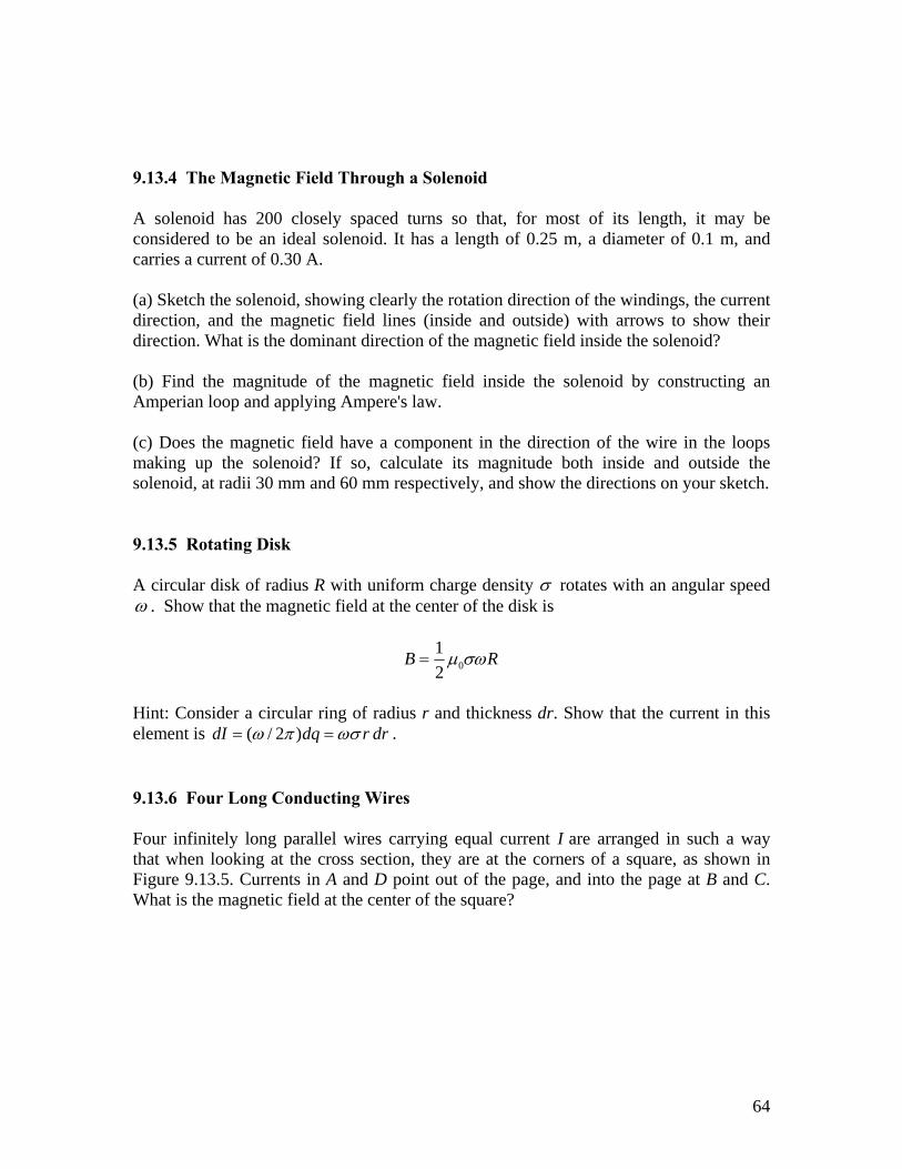
Hint: Consider a circular ring of radius r and thickness dr. Show that the current in this element is ( / 2 )dI dq r drω π ωσ= = . 9.13.6 Four Long Conducting Wires Four infinitely long parallel wires carrying equal current I are arranged in such a way that when looking at the cross section, they are at the corners of a square, as shown in Figure 9.13.5. Currents in A and D point out of the page, and into the page at B and C. What is the magnetic field at the center of the square?
64
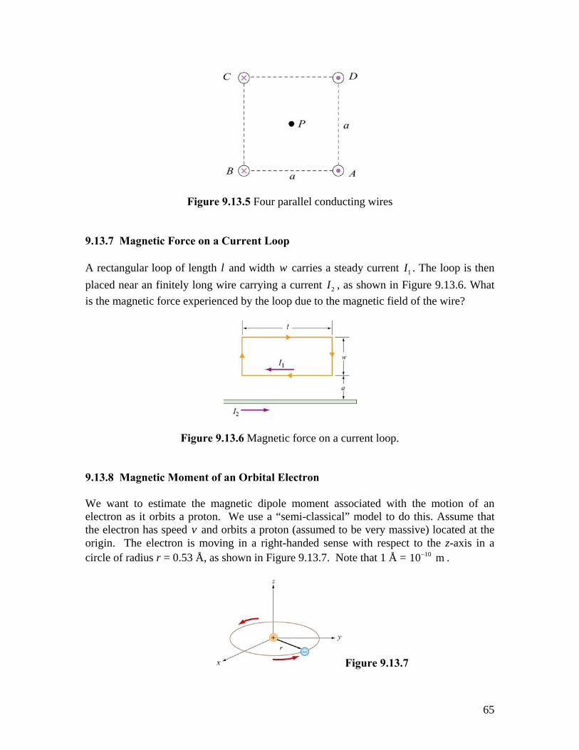
Figure 9.13.5 Four parallel conducting wires 9.13.7 Magnetic Force on a Current Loop A rectangular loop of length l and width carries a steady current w 1I . The loop is then placed near an finitely long wire carrying a current 2I , as shown in Figure 9.13.6. What is the magnetic force experienced by the loop due to the magnetic field of the wire?
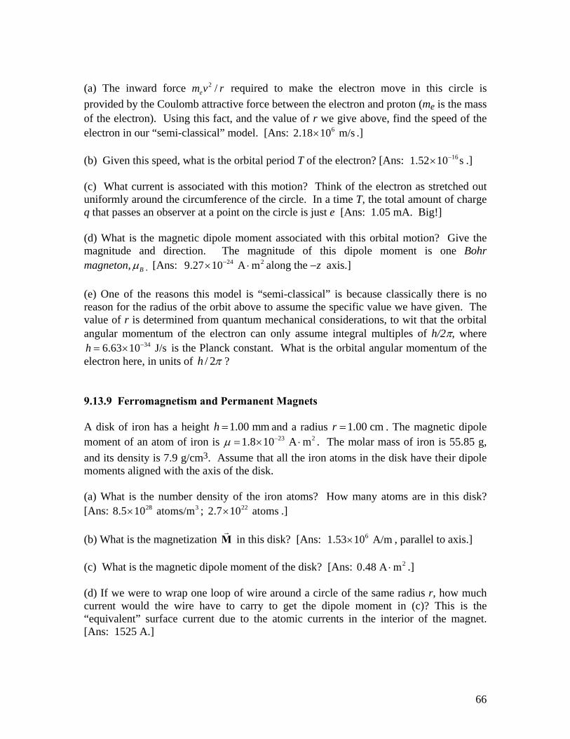
Figure 9.13.6 Magnetic force on a current loop. 9.13.8 Magnetic Moment of an Orbital Electron We want to estimate the magnetic dipole moment associated with the motion of an electron as it orbits a proton. We use a “semi-classical” model to do this. Assume that the electron has speed v and orbits a proton (assumed to be very massive) located at the origin. The electron is moving in a right-handed sense with respect to the z-axis in a circle of radius r = 0.53 Å, as shown in Figure 9.13.7. Note that 1 Å = . 1010 m−
Figure 9.13.7
65
(a) The inward force required to make the electron move in this circle is provided by the Coulomb attractive force between the electron and proton (me is the mass of the electron). Using this fact, and the value of r we give above, find the speed of the electron in our “semi-classical” model. [Ans: .]
2 /em v r
62.18 10 m/s× (b) Given this speed, what is the orbital period T of the electron? [Ans: .] 161.52 10 s−× (c) What current is associated with this motion? Think of the electron as stretched out uniformly around the circumference of the circle. In a time T, the total amount of charge q that passes an observer at a point on the circle is just e [Ans: 1.05 mA. Big!] (d) What is the magnetic dipole moment associated with this orbital motion? Give the magnitude and direction. The magnitude of this dipole moment is one Bohr magneton, Bµ . [Ans: along the −z axis.] 24 29.27 10 A m−× ⋅ (e) One of the reasons this model is “semi-classical” is because classically there is no reason for the radius of the orbit above to assume the specific value we have given. The value of r is determined from quantum mechanical considerations, to wit that the orbital angular momentum of the electron can only assume integral multiples of h/2π, where
is the Planck constant. What is the orbital angular momentum of the electron here, in units of
346.63 10 J/sh −= ×/ 2h π ?
9.13.9 Ferromagnetism and Permanent Magnets A disk of iron has a height and a radius 1.00 mmh = 1.00 cmr = . The magnetic dipole moment of an atom of iron is 23 21.8 10 A mµ −= × ⋅ . The molar mass of iron is 55.85 g, and its density is 7.9 g/cm3. Assume that all the iron atoms in the disk have their dipole moments aligned with the axis of the disk. (a) What is the number density of the iron atoms? How many atoms are in this disk? [Ans: ; .] 28 38.5 10 atoms/m× 222.7 10 atoms× (b) What is the magnetization in this disk? [Ans: , parallel to axis.] M 61.53 10 A/m× (c) What is the magnetic dipole moment of the disk? [Ans: 20.48 A m⋅ .]
(d) If we were to wrap one loop of wire around a circle of the same radius r, how much current would the wire have to carry to get the dipole moment in (c)? This is the “equivalent” surface current due to the atomic currents in the interior of the magnet. [Ans: 1525 A.]
66
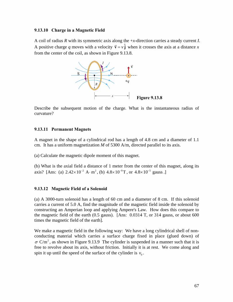
9.13.10 Charge in a Magnetic Field A coil of radius R with its symmetric axis along the +x-direction carries a steady current I. A positive charge q moves with a velocity ˆv=v j when it crosses the axis at a distance x from the center of the coil, as shown in Figure 9.13.8.
Figure 9.13.8
Describe the subsequent motion of the charge. What is the instantaneous radius of curvature? 9.13.11 Permanent Magnets A magnet in the shape of a cylindrical rod has a length of 4.8 cm and a diameter of 1.1 cm. It has a uniform magnetization M of 5300 A/m, directed parallel to its axis. (a) Calculate the magnetic dipole moment of this magnet. (b) What is the axial field a distance of 1 meter from the center of this magnet, along its axis? [Ans: (a) , (b) , or .] 2 22.42 10 A m−× ⋅ 94.8 10 T−× 54.8 10 gauss−× 9.13.12 Magnetic Field of a Solenoid (a) A 3000-turn solenoid has a length of 60 cm and a diameter of 8 cm. If this solenoid carries a current of 5.0 A, find the magnitude of the magnetic field inside the solenoid by constructing an Amperian loop and applying Ampere's Law. How does this compare to the magnetic field of the earth (0.5 gauss). [Ans: 0.0314 T, or 314 gauss, or about 600 times the magnetic field of the earth]. We make a magnetic field in the following way: We have a long cylindrical shell of non-conducting material which carries a surface charge fixed in place (glued down) of
, as shown in Figure 9.13.9 The cylinder is suspended in a manner such that it is free to revolve about its axis, without friction. Initially it is at rest. We come along and spin it up until the speed of the surface of the cylinder is .
2 C/mσ
0v
67
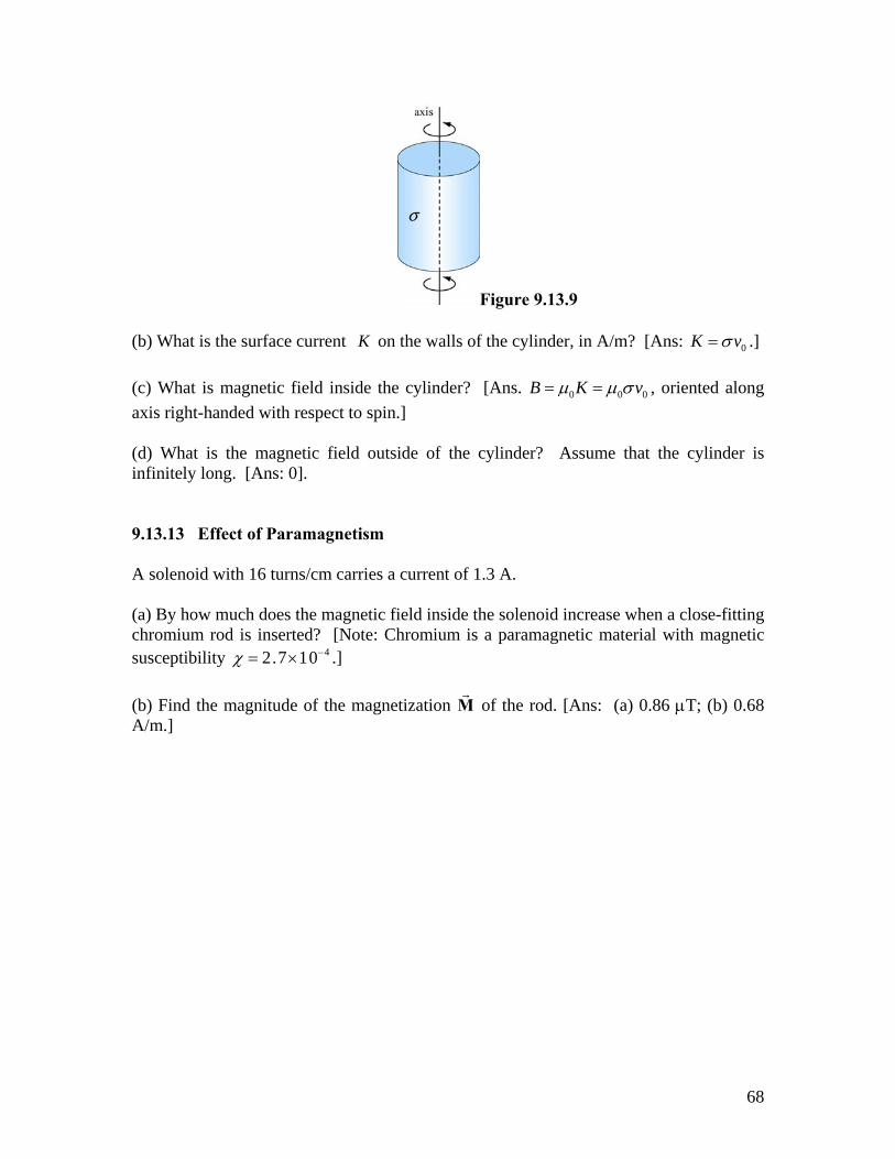
Figure 9.13.9 (b) What is the surface current K on the walls of the cylinder, in A/m? [Ans: 0K vσ= .] (c) What is magnetic field inside the cylinder? [Ans. 0 0 0B K vµ µ σ= = , oriented along axis right-handed with respect to spin.] (d) What is the magnetic field outside of the cylinder? Assume that the cylinder is infinitely long. [Ans: 0]. 9.13.13 Effect of Paramagnetism A solenoid with 16 turns/cm carries a current of 1.3 A. (a) By how much does the magnetic field inside the solenoid increase when a close-fitting chromium rod is inserted? [Note: Chromium is a paramagnetic material with magnetic susceptibility .] 42.7 10χ −= × (b) Find the magnitude of the magnetization M of the rod. [Ans: (a) 0.86 µT; (b) 0.68 A/m.]
68