Embed Size (px)
Citation preview
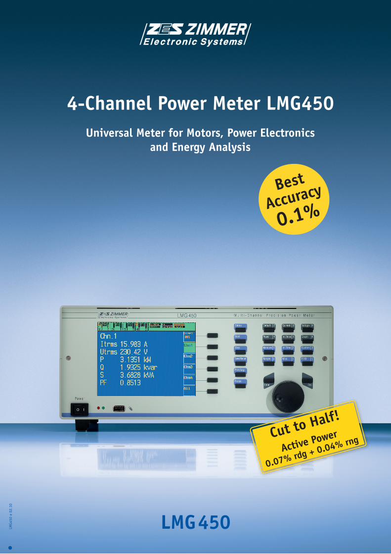
LMG450
4-Channel Power Meter LMG450Universal Meter for Motors, Power Electronics
and Energy Analysis
LMG4
50 e
02.
10
Best
Accuracy
0.1%
Active Power
0.07% rdg + 0.04% rngCut to Half!
General The four-channel LMG450 power meter is another advanced product from ZES ZIMMER LMG series of precision power meters, tried and tested and with great acceptance in the market. It is designed as a uni-versal meter for the entire field
of power electronics and net-work analysis. It can be used in practically all power electronics applications, in development and test systems, in quality as-surance and maintenance. It is fully frequency inverter compatible.
Of course, it can also be used for measurements in motors, transformers, conventional and switched power supply units. It is also suitable for mains analysis measurements.
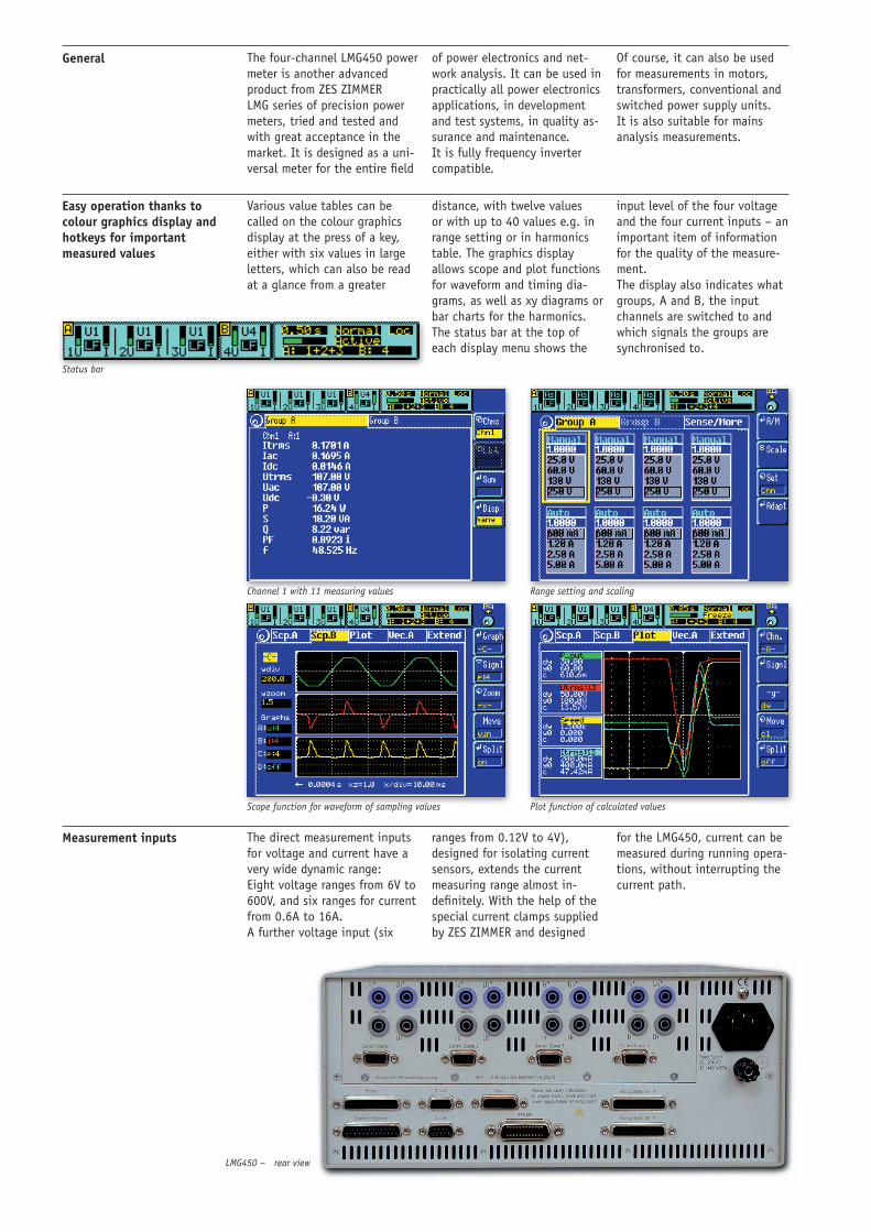
Easy operation thanks to colour graphics display and hotkeys for important measured values
Various value tables can be called on the colour graphics display at the press of a key, either with six values in large letters, which can also be read at a glance from a greater
distance, with twelve values or with up to 40 values e.g. in range setting or in harmonics table. The graphics display allows scope and plot functions for waveform and timing dia-grams, as well as xy diagrams or bar charts for the harmonics. The status bar at the top of each display menu shows the
input level of the four voltage and the four current inputs – an important item of information for the quality of the measure-ment. The display also indicates what groups, A and B, the input channels are switched to and which signals the groups are synchronised to.
Status bar
Channel 1 with 11 measuring values Range setting and scaling
Scope function for waveform of sampling values Plot function of calculated values
Measurement inputs The direct measurement inputs for voltage and current have a very wide dynamic range: Eight voltage ranges from 6V to 600V, and six ranges for current from 0.6A to 16A. A further voltage input (six
ranges from 0.12V to 4V), designed for isolating current sensors, extends the current measuring range almost in-definitely. With the help of the special current clamps supplied by ZES ZIMMER and designed
for the LMG450, current can be measured during running opera-tions, without interrupting the current path.
LMG450 – rear view
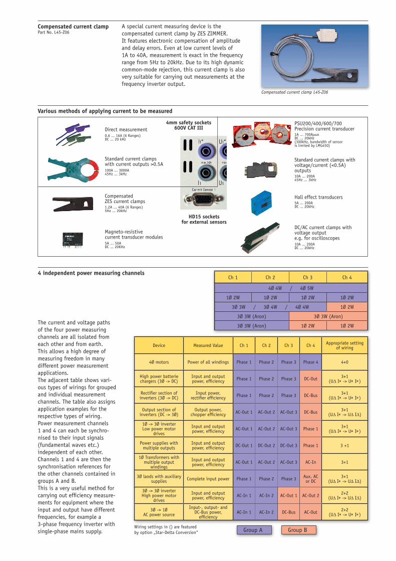
Ch 1 Ch 2 Ch 3 Ch 4
4Ø 4W / 4Ø 5W
1Ø 2W 1Ø 2W 1Ø 2W 1Ø 2W
3Ø 3W / 3Ø 4W / 4Ø 4W 1Ø 2W
3Ø 3W (Aron) 3Ø 3W (Aron)
3Ø 3W (Aron) 1Ø 2W 1Ø 2W
Device Measured Value Ch 1 Ch 2 Ch 3 Ch 4 Appropriate setting of wiring
4Ø motors Power of all windings Phase 1 Phase 2 Phase 3 Phase 4 4+0
High power batterie chargers (3Ø -> DC)
Input and output power, efficiency Phase 1 Phase 2 Phase 3 DC-Out 3+1
(UD I* -> U* I*)
Rectifier section of inverters (3Ø -> DC)
Input power,rectifier efficiency Phase 1 Phase 2 Phase 3 DC-Bus 3+1
(UD I* -> U* I*)
Output section of inverters (DC -> 3Ø)
Output power, chopper efficiency AC-Out 1 AC-Out 2 AC-Out 3 DC-Bus 3+1
(UD I* -> UD ID)
1Ø -> 3Ø inverterLow power motor
drives
Input and output power, efficiency AC-Out 1 AC-Out 2 AC-Out 3 Phase 1 3+1
(UD I* -> U* I*)
Power supplies with multiple outputs
Input and output power, efficiency DC-Out 1 DC-Out 2 DC-Out 3 Phase 1 3 +1
1Ø Transformers with multiple output
windings
Input and output power, efficiency AC-Out 1 AC-Out 2 AC-Out 3 AC-In 3+1
3Ø laods with auxiliary supplies Complete input power Phase 1 Phase 2 Phase 3 Aux. AC
or DC3+1
(UD I* -> UD ID)
3Ø -> 3Ø inverterHigh power motor
drives
Input and output power, efficiency AC-In 1 AC-In 2 AC-Out 1 AC-Out 2 2+2
(UD I* -> UD ID)
3Ø -> 1Ø AC power source
Input-, output- and DC-Bus power,
efficiencyAC-In 1 AC-In 2 DC-Bus AC-Out 2+2
(UD I* -> U* I*)
4mm safety sockets 600V CAT IIIDirect measurement
Standard current clamps with current outputs >0.5A
Compensated ZES current clamps
HD15 sockets for external sensors
Magneto-resistive current transducer modules
PSU200/400/600/700 Precision current transducer
Standard current clamps with voltage/current (<0.5A) outputs
Hall effect transducers
DC/AC current clamps with voltage output e.g. for oscilloscopes
0.6 ... 16A (6 Ranges) DC ... 20 kHz
100A ... 3000A 45Hz ... 3kHz
1.2A ... 40A (6 Ranges) 5Hz ... 20kHz
5A ... 50A DC ... 20KHz
1A ... 700Apeak DC ... 20kHz (300kHz, bandwidth of sensor is limited by LMG450)
10A ... 200A 45Hz ... 3kHz
5A ... 200A DC ... 20kHz
10A ... 200A DC ... 20kHz
Compensated current clamp Part No. L45-Z06
A special current measuring device is the compensated current clamp by ZES ZIMMER. It features electronic compensation of amplitude and delay errors. Even at low current levels of 1A to 40A, measurement is exact in the frequency range from 5Hz to 20kHz. Due to its high dynamic common-mode rejection, this current clamp is also very suitable for carrying out measurements at the frequency inverter output.
Compensated current clamp L45-Z06
Various methods of applying current to be measured
4 independent power measuring channels
The current and voltage paths of the four power measuring channels are all isolated from each other and from earth. This allows a high degree of measuring freedom in many different power measurement applications. The adjacent table shows vari-ous types of wirings for grouped and individual measurement channels. The table also assigns application examples for the respective types of wiring. Power measurement channels 1 and 4 can each be synchro-nised to their input signals (fundamental waves etc.) independent of each other. Channels 1 and 4 are then the synchronisation references for the other channels contained in groups A and B. This is a very useful method for carrying out efficiency measure-ments for equipment where the input and output have different frequencies, for example a 3-phase frequency inverter with single-phase mains supply.
Wiring settings in () are featured by option „Star-Delta Conversion“ Group A Group B
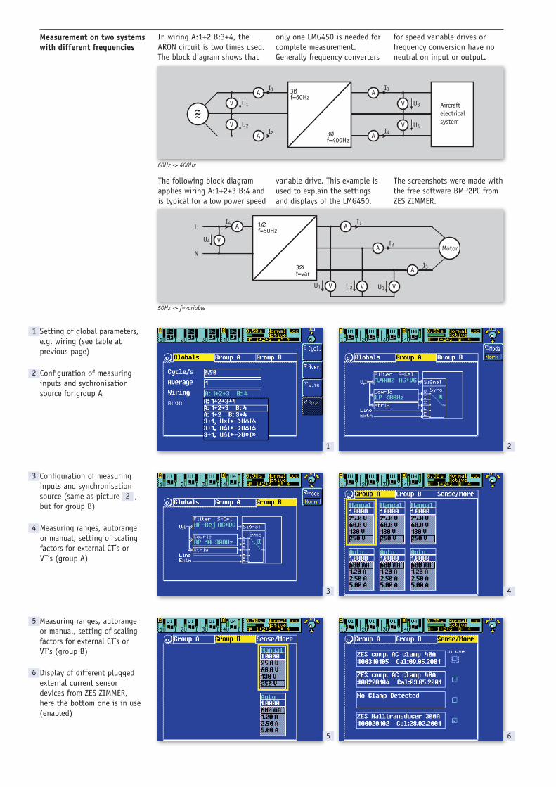
V U4
A
A
I3
I4U2
A
A
I1
I2V
U1V Aircraft electrical system
V U3
3Øf=400Hz
3Øf=60Hz
˜
3f=var
1f=50HzL
N
VU4
AI4
A
VU1 VU2 VU3
AI1
AI2
I3
Motor
1
3 4
5 6
2
Measurement on two systems with different frequencies
In wiring A:1+2 B:3+4, the ARON circuit is two times used. The block diagram shows that
The following block diagram applies wiring A:1+2+3 B:4 and is typical for a low power speed
only one LMG450 is needed for complete measurement. Generally frequency converters
for speed variable drives or frequency conversion have no neutral on input or output.
60Hz -> 400Hz
variable drive. This example is used to explain the settings and displays of the LMG450.
The screenshots were made with the free software BMP2PC from ZES ZIMMER.
50Hz -> f=variable
Setting of global parameters, e.g. wiring (see table at previous page)
Configuration of measuring inputs and sychronisation source for group A
Configuration of measuring inputs and synchronisation source (same as picture , but for group B)
Measuring ranges, autorange or manual, setting of scaling factors for external CT’s or VT’s (group A)
Measuring ranges, autorange or manual, setting of scaling factors for external CT’s or VT’s (group B)
Display of different plugged external current sensor devices from ZES ZIMMER, here the bottom one is in use (enabled)
1
3
4
5
6
2
2
7 8
9 10
11 12
13 14
1615
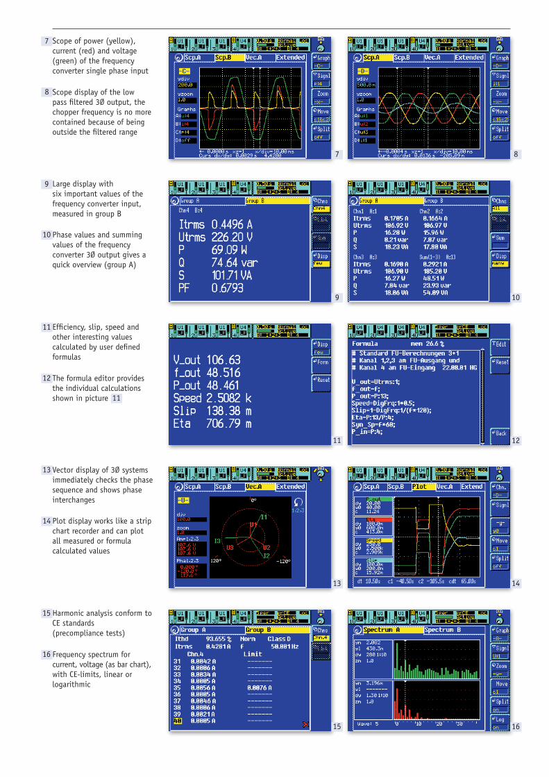
Scope of power (yellow), current (red) and voltage (green) of the frequency converter single phase input
Scope display of the low pass filtered 3Ø output, the chopper frequency is no more contained because of being outside the filtered range
Large display with six important values of the frequency converter input, measured in group B
Phase values and summing values of the frequency converter 3Ø output gives a quick overview (group A)
Efficiency, slip, speed and other interesting values calculated by user defined formulas
The formula editor provides the individual calculations shown in picture
Vector display of 3Ø systems immediately checks the phase sequence and shows phase interchanges
Plot display works like a strip chart recorder and can plot all measured or formula calculated values
Harmonic analysis conform to CE standards (precompliance tests)
Frequency spectrum for current, voltage (as bar chart), with CE-limits, linear or logarithmic
7
8
9
10
11
12
13
14
15
16
11
3f=var
1f=50HzL
N
VU4
AI4
A
VU1
I3
Motor
AI1
VU3VU2
AI2
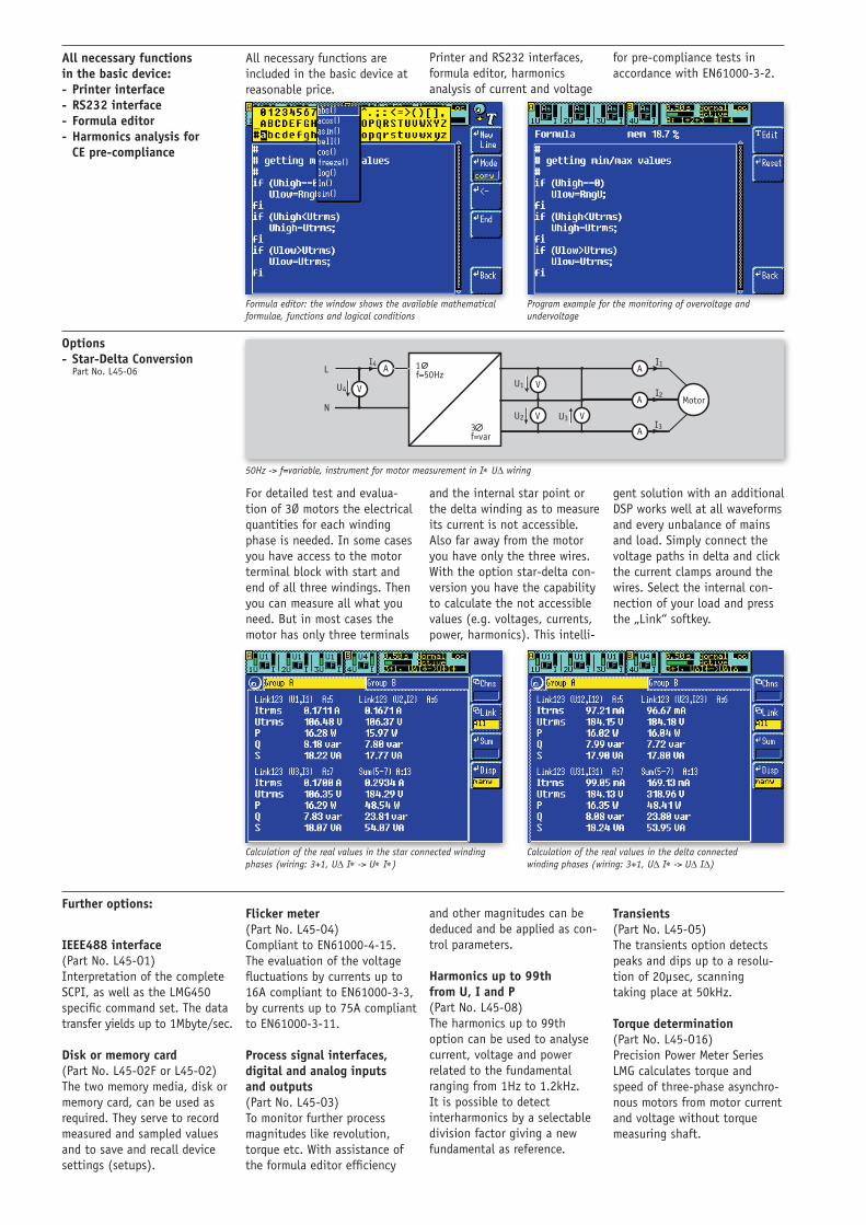
All necessary functions in the basic device: - Printer interface - RS232 interface - Formula editor - Harmonics analysis for CE pre-compliance
All necessary functions are included in the basic device at reasonable price.
Formula editor: the window shows the available mathematical formulae, functions and logical conditions
Program example for the monitoring of overvoltage and undervoltage
Further options:
IEEE488 interface (Part No. L45-O1) Interpretation of the complete SCPI, as well as the LMG450 specific command set. The data transfer yields up to 1Mbyte/sec. Disk or memory card (Part No. L45-O2F or L45-O2) The two memory media, disk or memory card, can be used as required. They serve to record measured and sampled values and to save and recall device settings (setups).
Flicker meter (Part No. L45-O4) Compliant to EN61000-4-15. The evaluation of the voltage fluctuations by currents up to 16A compliant to EN61000-3-3, by currents up to 75A compliant to EN61000-3-11. Process signal interfaces, digital and analog inputs and outputs (Part No. L45-O3) To monitor further process magnitudes like revolution, torque etc. With assistance of the formula editor efficiency
and other magnitudes can be deduced and be applied as con-trol parameters. Harmonics up to 99th from U, I and P (Part No. L45-O8) The harmonics up to 99th option can be used to analyse current, voltage and power related to the fundamental ranging from 1Hz to 1.2kHz. It is possible to detect interharmonics by a selectable division factor giving a new fundamental as reference.
Options - Star-Delta Conversion Part No. L45-O6
For detailed test and evalua-tion of 3Ø motors the electrical quantities for each winding phase is needed. In some cases you have access to the motor terminal block with start and end of all three windings. Then you can measure all what you need. But in most cases the motor has only three terminals
and the internal star point or the delta winding as to measure its current is not accessible. Also far away from the motor you have only the three wires. With the option star-delta con-version you have the capability to calculate the not accessible values (e.g. voltages, currents, power, harmonics). This intelli-
gent solution with an additional DSP works well at all waveforms and every unbalance of mains and load. Simply connect the voltage paths in delta and click the current clamps around the wires. Select the internal con-nection of your load and press the „Link“ softkey.
50Hz -> f=variable, instrument for motor measurement in I* UD wiring
Calculation of the real values in the star connected winding phases (wiring: 3+1, UD I* -> U* I*)
Calculation of the real values in the delta connected winding phases (wiring: 3+1, UD I* -> UD ID)
Printer and RS232 interfaces, formula editor, harmonics analysis of current and voltage
for pre-compliance tests in accordance with EN61000-3-2.
Transients (Part No. L45-O5) The transients option detects peaks and dips up to a resolu-tion of 20µsec, scanning taking place at 50kHz. Torque determination (Part No. L45-O16) Precision Power Meter Series LMG calculates torque and speed of three-phase asynchro-nous motors from motor current and voltage without torque measuring shaft.
3 Phase/ 4 Wire
3 Phase/ 3 Wire
Line to Line Voltage
Line to Neutral/Earth
66/115V 115V 66V
120V 120V 69V
120/208V 208V 120V
240V 240V 139V
230/400V 400V 230V
277/480V 480V 277V
500V 500V 289V
400/690V 690V 400V
1000V 1000V 578V
Voltage measuring ranges Nominal value /V 6 12.5 25 60 130 250 400 600 Maximum trms value /V 7.2 14.4 30 60 130 270 560 720 Maximum peak value for full scale /V 12.5 25 50 100 200 400 800 1600 Overload capability 1500V for 1s Input impedance 1MΩ, 20pF
Current measuring ranges Nominal value /A 0.6 1.2 2.5 5 10 16 Maximum trms value /A 1.3 2.6 5.2 10 18 18 Maximum peak value for full scale /A 1.875 3.75 7.5 15 30 60 Overload capability 18A permanent, 50A for 1s, 150A for 20ms Input impedance 2mΩ
Isolation All direct current and voltage inputs of power measuring channels against each other and against earth isolated, max. 600V/CATIII
Voltage measuring ranges for external isolated current transduceers Nominal value /V 0.12 0.25 0.5 1 2 4 Maximum trms value /V 0.15 0.3 0.6 1.2 2.5 5 Maximum peak value for full scale /V 0.25 0.5 1 2 4 8 Overload capability 250V for 1s Input impedance 100kΩ, 10pF
Measuring range selection Automatic, manual or remotely controlled
Measuring accuracy Accuracies based on: 1. sinusoidal voltage and current 4. definition of power range as the product of 2. ambient temperature (23 ± 3) °C current and voltage range, 0 ≤ IλI ≤ 1, (λ=Power factor=P/S) 3. warm up time 1h 5. calibration interval 12 month Other values All other values are derived from the current, voltage and active power values. Accuracies for derived values depend on the functional relationship (e.g. S = I * U, DS/S = DI/I + DU/U)
Synchronization The measurement is synchronized on the signals period. There is a choice to determine the period from u(t), i(t), p(t), further u2(t), i2(t) by using a settable filter . By this very stable readings are achieved, even at signals of pulse width modulated frequency inverter and amplitude modulated electronic ballast, synchronization also with external signal or „Line“
Scope function Graphical representation of sampled values over the time
Plot function Time diagram of max. four readings, minimal resolution 50ms
Harmonic analysis prCE Harm Measuring of current and voltage according to EN61000-4-7 with evaluation according to EN61000-3-2 (Pre-compliance)
Harmonic analysis Harm100 Analysis of current, voltage and power up to 99th harmonics (max. 10kHz), in total 100 harmonics, when including DC part. Fundamental in the range from 1Hz to 1.2kHz. By selectable integer divider (1...50) a new reference fundamental can be created as to detect interharmonics.
Flicker measuring Flicker Meter according to EN61000-4-15 with evaluation according to EN61000-3-3
Transients – monitoring and storing Storing and graphical displaying of transients with a resolution of 20µs. Storing depth is 1.4 Millions sample values/channel, selectable recording duration from 0.05 to 60 seconds. Adjustable pre-trigger, different possibilities of triggering
Computer interfaces Interfaces: RS232 and IEEE488.2, only one interface can be used at the same time Remote control All functions can be remote controlled, keyboard lock for measuring parameters available Output data Output of all readable data, data formats equal for all interface types, SCPI command set Transfer rate RS232: max.115200 Baud, IEEE488.2: max. 1MByte/sec
Printer interface Parallel PC-Printer interface with 25-pin SUB-D socket for printing measuring values, tables, graphics to matrix, inkjet or laser printers
Processing signal interface 25 pin SUB-D socket with (The option processing signal interface can be built in twice): • fouranaloginputsforregistrationofprocessmagnitudes(16Bit,±10V, 1kHz) • fouranalogoutputsforoutputofreadingsormeasuredmagnitudes(16Bit,±10V, 100kHz) • fourdigitalinputsforregistrationofstates(1kHz,ULOW<1V, UHIGH=4...60V/2.5mA) • fourdigitaloutputstosignalstatesandalarms(opencollector,outputhighmax.30V@100µA,outputlowmax.1.5V@100mA) •oneinputforregistrationoffrequency(0.1Hz...500kHz)androtationdirectionofmotors(ULOW<1V, UHIGH=4...10V, 1MΩ) In- and outputs are isolated groupwise against each other and against the other electronics (testing voltage 500V)
Technical Data
Dimensioning of insulation for all standard low voltages
The measurement inputs are dimensioned for 600V/CAT III, with option L45-O15 up to 1000V. This makes it possible to measure in all standard 3-phase low voltage networks. The adjacent table shows that the voltage “Line to Neutral/Earth” is always less than 600V.
Measuring accuracy ± (% of measuring value + % of measuring range)
DC 1Hz..1kHz 45...65Hz, AC-Coupling 1kHz..5kHz 5kHz...20kHz
Voltage 0.2+0.2 0.1+0.1 0.05+0.05 0.2+0.2 0.3+0.4
Current (direct) 0.4+0.4 0.15+0.1 0.05+0.05 0.2+0.2 0.5+0.5
Active power (direct) 0.5+0.5 0.2+0.1 0.07+0.04 0.3+0.2 0.6+0.5
Current (via ext. current transducer) 0.2+0.2 0.1+0.1 0.05+0.05 0.2+0.2 0.3+0.4
Active power (via ext. current transducer) 0.3+0.3 0.15+0.1 0.07+0.04 0.3+0.2 0.6+0.5
Subject to technical changes, especially to improve the product, at any time without prior notification.
LMG450 accessories ZES ZIMMER compensated current clamps Nominal value /A 1.25 2.5 5 10 20 40 Permissible trms value /A 2.5 5.0 10 20 40 80 Permissible peak value for full scale /A 3.75 7.5 15 30 60 120 Overload capability 500A for 1s Max. cord diameter 12mm Isolation 300V/CATIII, 600V/CATII Part No. L45-Z06 (1 pc.) L45-Z07 (Set of 4 pc.)
Adapter for 3-phase measurements Part No. LMG-MAK3
• CEE-Plug,5pins,16A,2msupplycord • CEE-Socket,5pins,16A,forEUT • SocketforsupplyingthemeterLMG450 • 4mmsafetysockets,measuringaccesstocurrentandvoltage • Safetyacc.IEC61010:300V/CATIII
Hall current sensors for range extension
RS232 - Ethernet - converter, 10/100mbit Part No. L45-Z318
Current transducers with Hall effect sensors for range extension of LMG450, DC...20kHz, accuracy class 0,5 connected to LMG450 via HD15 sensor input, incorporated EEPROM for scaling and adjustment data as well as data for automatically setting of appropriate current range
Other data Display STN colour display, 320 x 240 pixel, 5,7’’ Dimensions - Bench case, W 320mm x H 147mm x D 307mm - 19‘‘-chassis, 84PU, 3HU, D 307mm Weight about 6,5kg Protection class EN61010 (IEC1010, VDE0411), protection class I, overvoltage category III Electromagnetic compatibility EN50081, EN50082 Protection system IP20 in accordance to DIN40050 Operating/storage temperature 0...40°C, -20...50°C Climatic class KYG in accordance to DIN40040 Power supply 85...264V, 47...440Hz, about 45W
Part No. Current Supply nominal trms peak L45-Z28-Hall50 35A 50A 70A Internally L45-Z28-Hall100 60A 100A 120A by LMG450 L45-Z28-Hall200 120A 200A 240A via HD15 L45-Z29-Hall300 250A 300A 500A Externally e.g. with L45-Z29-Hall500 400A 500A 800A ZES power supply for L45-Z29-Hall1000 600A 1000A 1200A up to four sensors L45-Z29-Hall2000 1000A 2000A 2100A Part No. SSU-4
External adaptor, all connectors will fixed at the LMG, supply by LMG
Power supply unit for up to 4 Sensors Part No. SSU-4
Power supply unit for up to 4 Sensors for L45-Z29 and PSU-600 series, device fitting under LMG450/95, design equal to NDL5 (see below)
Measuring accuracy of clampCurrent: ± (% of measuring value + % of measuring range) / Phase: degrees
1Hz...10Hz 10Hz...45Hz 45Hz...1kHz 1kHz...5kHz 5kHz...20kHz 20kHz...50kHz
Current 1.5+0.25 0.4+0.15 0.15+0.05 0.3+0.15 1.0+0.25 4.0+0.5
Phase 6 3 0.5 2 6 20
PC Software Order no. LMG-CONTROL-B Order no. LMG-CONTROL-WA
PC software for data transfer, configuration and visualisation, Modular design, saves and loads device configurations. Interactive mode to set up the measurements. Recording and storage adds timestamps with accuracy in the range of milliseconds. Analysing modules for different applications. Basic version is free of cost. Additional module for LMG-CONTROL, logging and analysis of all sampling values of the LMG, harmonic analysis up to 1MHz, frameanalyser, logging of transients.
Germany (headquarter) ZES ZIMMER Electronic Systems GmbH
Tabaksmühlenweg 30 • D-61440 Oberursel/GermanyTel. +49 6171 628750 • Fax +49 6171 52086
www.zes.com • [email protected]
United States ZES ZIMMER Inc.
4808 Santa Monica Ave. • San Diego, CA 92107 Phone +1 760 550-9371
www.zes.com • [email protected]