Embed Size (px)
Citation preview

4.!,’, .< ?-..‘!..c.d (2%$’.‘.. r’.. ‘- ,?.L...-
!TECHNICAL MEMORANDUMS,,..
NATIONAL ADVISORY COMMITTEE FOR’’=ONiUTICS
1?0. 999
STRESS ANALYSIS OF CIRCULAR FRAMES
By H. Fahlbusch and W. Wegner
LuftfahrtforschungVol. 18, No. 4, April 22, 1941
Verlag von R, Oldenbourgi IN.inchenund Berlin
,, . .. ., :.. ,- -.,., ,., ,.. .,,, - . . . -., ..,.., ,,Washington
,. . ...
December 1941
1’ .
https://ntrs.nasa.gov/search.jsp?R=19930094418 2018-09-07T23:22:47+00:00Z
—
‘~lllllllllll~l31176014404181
. NAT ION’A!i”ADVI SORf-”COMMITTEE” F.OR:AER.C)~.A~TICS
TECHNICAL MEMORANDUM
,,. .. . . . . . .. ..
NO. 999. . ..;,
STRESS ANALYSIS Ol? CIRCULAR FRAMES+,, .
By H. Fahlbusch and W+ Wegner,..,..... :.:,...,.,:,... ..
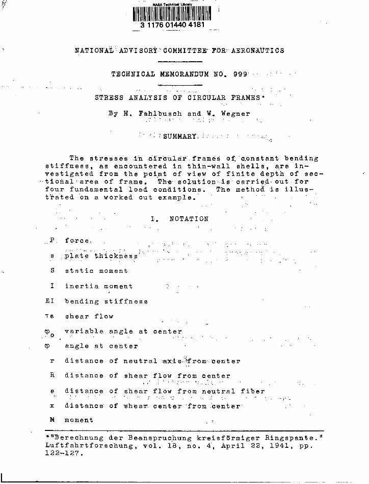
:.,.-”.:. .SUMMARY, ~ ~ ‘-::,,..
The stresses .in’”..~.fr~ultid’,frames of,”c;onsta.ntbendingstiffness, as encountered in thin-wall shells, are in-vestigated from the point of view of finite depth of sec-
-tionalarea of frame. Thesolution...is carri~,d-out. forfour fundamental load conditions. The method is illus-t-tia’ted‘on a,worked out example.’ ;’””’ . . .
...,.
,., . . ,., 1. NOTATION,,.., ..,,
P
s
s
I
EI
7s
r
R
static moment
inertia moment.,
. .
bending stiffness
shear flow .,-,, ,.variable angle at center
. .. .... . ,,.“angle at center
distance of neutral :ak;is.~~from’center,>
distance of shear flow from center.,, ., .,,>’..., ;:...’..,.,:.....”’ ,! ‘.distance of shear flow from neutral fiber
.,
e,.. . . . ,,,, ,.,, ,,,....,>.... ... .:,,., :.. . ,.j...,x distance’ of ‘s”hear.:center ‘from “center
M moment
*llBerechnung der Be.a,’fispr~chung.kreisftlrmiger Ringspante. 11
Luftfahrtforscnung , vol. 1’”8,no= 4“,April 22, 1941, pp.122-127.
II . -. —.

2
B
N
2
x
8
larvid10Rcanthe
XAGA Technical Mernorandnrn No. 99? ;:, ;;- .
bending moment .,,
normal force,. .,’.
transverse force.
.. . . . .statically undetermined quantity”
load and coeffi.cient, respect ively
. ,, ..,.:1-1;. THE FRAME IQU.ILIB.RIUM,. ..;, ; ..,’”- . ,..
......... .,
For the.”ayTli:cAtioh of transverse. forces in a circ~-,.
Rshell wit’h large’ ratio ~, circul’i:r‘f.rarnesare Pr”o.-.
ed. They are in equilibrium with the concentratedds and the shear forces from the shell. Eech loadinghe divided into the transverse force passing throughelastic centroid of the shell and the moment (fig. 1).
ingsheala).
With
Theuncle,r fl
transverse force produces, as a result ‘O”f’bendr transverse force, a sinusoidally distributedow in the shell that reaches ‘~o’:the frame” (fig.
,..
?-s = :s
.:
denoting the mfunction
represents the
The distafor sinusoidal
x
ome nt
she
I =ITR3S
of inertia of the
ar
Ts
fl?ow
J?_fiR
va
.nce of tva.riati
heon,
,.she(fro
~
R//Tsdu
“(-) ..=
g2
riat
ar cm th
& ‘Rn
circul
ion.
enter oe cente
= 1.27
Ela
cmo
,.
shell , the
ircular.vnts to
half
—.— .. .-, .- —.
NilCA.T.e;chni’cal;Memo r,andum No-:.99%. 3
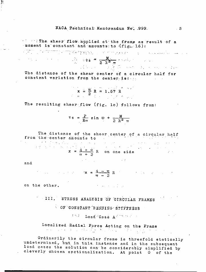
,, :~}The. shear” fl.o.w..hp;pli(ed-at$the f:ram~ as result of a~~moment is” con stant.”and ,~mount.s:t.o(fig:.:1.6):
,, ,.,
The, distance of the shear center of a circular half forconstant variation from the center: is.: :
.- -’, . .. ,.
x= ;R~ 1’:57 R, .!.., ,“
The resulting shear, flow (fig. lc) follows from;
Ts. &sin Q+ MRn 2Re Tr
The distance of the shear center ,,?fa circular halffrom the: center &rnounts to : ,.,- I,
,~f.... ,... . . . . . ..””.... ,.. . ,..:,.
,.. . ,, ,,. .. . ,,, .,. . . .. .4++’R
.,, . ‘,’”x=— on one side ,.
17+2,.. ,
and
. . ‘x = 4,-,. ~R”lT - ~
: .,.’
on the other. ,-.
.111. “STRESS ANALys IS ‘(jr“01”’RCU~ARFRAMEs ‘
: -: ,;- LoadHCa$e A~””” “ ~.
Localized-Radial Force Acting on the Frame,.,. ..: ,. ,, i.”,, ,.,:,,. ,. .
Ordinarily the circular frame is threefold staticallyundetermined. but. in this. In.st:ance and in the subsequentload cases the solution can’be considerably simplified bycleverly chosen sectionalization . At point O of the

4 MAGA Te6hnical .Membr&ndum. No~ 9.99;
load in figure’2, the statically undetermined quantity isX3 = o. ‘The.signs for carrying: out the anazysts are given
in figure 4. The depth of the sectional area of the frame
is introduced by means of the ratio ~. The subsequent re-
sults are valid for @ (fig. 3).=
The elasticity equations re~d.
The displacement quantities generally follow at
EI 6ik =J
Bi Bk du
Determination of the bending moment curve B. in the
statically determined principal system referred to neutralfiber (fig. 4). The tangentially applied shear force ele-ment
sets up s.tpoint T in t~eframe the bending moment
dBo= - TS du e
The distance e follows f~om the geometric relation
e = R -r(sin CPo sin V + cos To COSQ)
Then the bending moment B. at Q is:
,9 Q
‘J
,!.’BoG-S sin Q. d~o + ~ sin ~
Jsin 2 To dCPo +
n l-l09
Ei.z&co’~@” sin CPo cos .90 dqo.Trf
.0 “ !..

1--
NA~A, Technica’1 Mernoiandwm
hence .. ..,..:, ... “. ‘:.””.
, .... ~o.l= P.{ ,, .9 -— i.~ ,:’og-=q;+..”r-~..:,~i~~\
No. :99~ ~~5
; ....:,-.“..
)+-R..
Ba=r (l- cos T) as a result of X2 = 1....’. ..: . .. ,,. :
For reasons of symmetry the “integration can te lim-ited to a half frame. .The,following loads and factorsare obtained. ,’ ..,.
fi :, .. . ,,,,...:’,”
EI tjlo =r (
,..
B1 % du= Pr ~- Rl/o
EI “~=o = Pr2” R(% -:2 “ “ ““: ~
EI il~. = ‘EI 623 > ra+’... ., :,. :. ....,.... .. ...
Solution of the ‘elasticity ‘eg.uations”gives the ‘magnitudeof.the. st,a$,i,cally,,undeter,min,edquantities, .r .~. , .:,
..4 :.. . ..:. .. .. . . . .. . ,,. , ,,
.Xl = - =., .X241-r ‘$(’-:-”iJ”’““
whence the ultimate bending moment ..’!. ..=’
. . . .. .. .. . . .. .
T( ——Pr. .g ~:in..~+=i-2TT )
; C,os.?p:-.’.l.’. (1)
., ,,.

............ . . . . . ,., . ,, .,,,,., ,, . ,
6 IJACA,?e’c,hnical Memorandum. No. .999
The final normal force follows from
.N= No +. XINl + X2N2 .,
The normal force No in the statically determined
principal system at po$nt cp %s obtained by’”splittingthe shear force element in the tangential component fol-lowed by integration from O to Q (fig. ”4“)
,,
dNo = - TS du COS (~ - ~o)
The norme.1 force distribution in the statically undeter-mined system then is ,.
and the transverse force variation
(2)
(3)
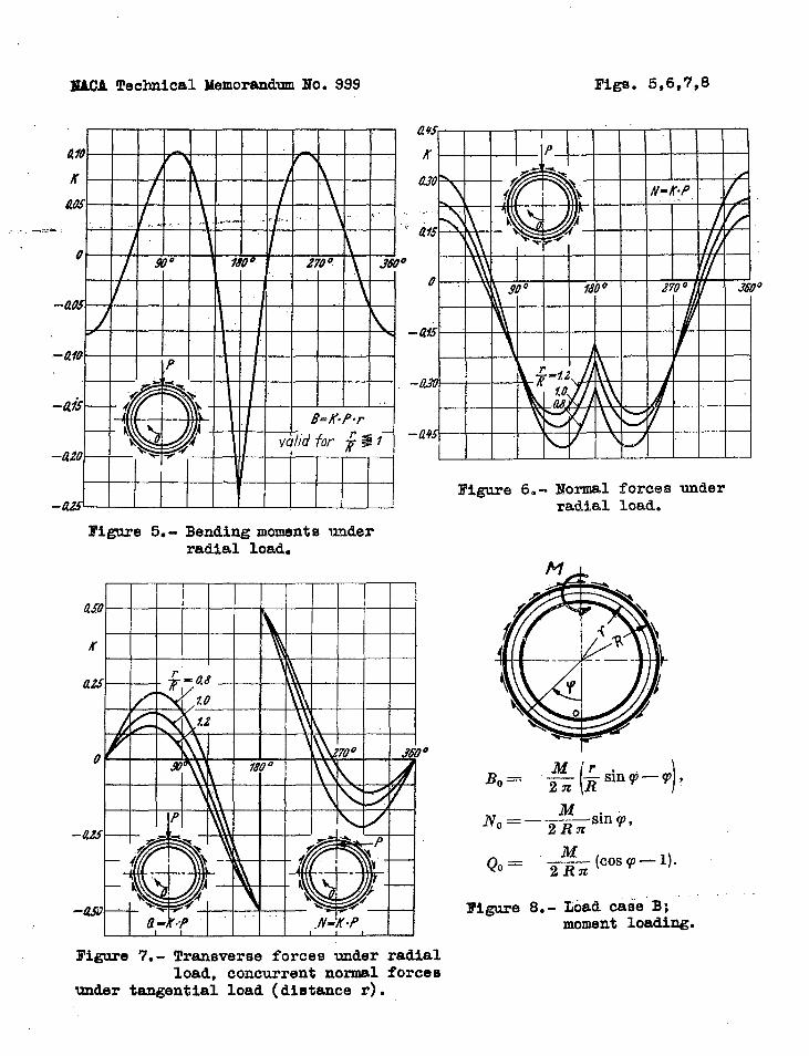
Figures 5 to 7 “show bending moments, normal force,and transverse force plotted against the frame circumfer-
ence. The ratio. ~ serves as parameter forR $=
1,
r–=le2, ~=o.8. . .R R .,’
Load Case 3
Localized Moment Acting Along a,
Diameter of th;e Frame (fi~i 8)
For this load the frame is simply statically unde-termined at point O. The elasticity equation reads

NACA Technical Memorandum No. ‘999, 7
630 + X3833 = o.
Bending moments, normal force-, and -transverse -force in. thestatically determined principal system are obtained as forcase A. The loads and factors are:
The statically undetermined quantity follows at
The final bending moment is
the final normal force is
—— . ——
N=-&1
sin V
and the final transverse force is
(,4)
(5)
(6)
as illustrated in figur.!es9 ,,t.o11... ,.
Load’ Case C
Localized Tangential Force Acting ,Along the Neutral Fiber,., ,..,
of the Frame at a Distance r from the Center “’
In this instance also the frame is simply staticallyundetermined at point 0. The procedure i’s the same .as
——

8 NACA Technical ~lernorandum”No”. 999
before,..
The intermediate an”d’’final results are;
Qo=& (‘4 sin CP + ,’I; Cos CP - —:~,,1
furthermore
and
——— .—...————.
IN=% ( 2R
Cp Cos q) + —r sin V - ~ )1sin V. )1
(7’)
(8j
(9)
B and Q are plotted in figures 13 and 14. N h~s thesame asp~ct as Q in load case A (fig. 7).

. . . ... .... ——.,
NACA Technical M“emorandum’No”O 99g””’.: 9
Localized Tangential Force Acting Alon&. $he:,outer,,=P.eri.phery,,
of the Frame at a Distance R from the Csnter (fig. 15)
The stresses, in this frame loading are obtained whenload case G id superposed by & moment of magnitudeM:> P (R- r); Then :,-’. ., ..,
(B=%” 2 sin q)‘m
-~cpcoscp-~sinq -q (lo)2R
.
L----
(11)
Figure 16 illustrates the bending moment distribution; N
‘N in &oad case C for ~ = 1has the same aspect as and
as Q in load case A at .:.= 1 (cf,. fig, 7). Q in load,...
case D has the same aspect as Q.jin load case+C at ~ = 1
(fig. 14).
IV. EXAMPLE.,, .,
* ,,,. ,. .,. .,
Find the stres’sks in ~ Ci’rc’ularframe with ratio
.- = 1.1 under the following loa:ds,;
(Fig. lT. )
By division’ of the ,forae’ P we get
. ,.., ,,,
.,
,., ..,., . . ,..’ .,

-——..-—- ——. -—,.. ,——.,.——..,,,
NACA Technical Memorandum No. 999
Load Case A: 0.9 1? = 1800 kg acting radially
c: 0.4 F = 800, kg acting tangentially
B: .40 mkg
,.
The resulting bending moment curve is fonnd, ..
numerically by superposition of the results from equations(1), (7), and (4), or by graphical superpositi~n of thebending moment curves from the basic losds illustrated infigures 5, 13, and 9. The same method applies to thenormal and the transverse force. Of gre~test interest isthe knowledge of the l~ngitudinal stresses from the bend-ing moments and normal forces.
BENDING MOMENTS (mkg) IN FRAME FROM
THE NUMERICAL SOLUTION
i It
90 “i80 180 270 360
A ““ ““””-:7.2 I 53,9’ ‘-1~1.~ -141.5
*
53.9’”’ -i7 .’2-3.0 0 0 3.0 0B., , ~,,. ,: ,2, + : 20””’0c’ ● , 20.0 -:2.7:’ 0 ‘
,..,Result -“37;2 5’3.6’ -1”~~.:’” ‘“-121.5’ 5&.’2 ‘1’-4”7.2
TABLE II
NORMAL FORCES “’(iikg) IN FRAME
FROM N,Ui$ERICAL SOLUTIONS e,.
,,. —
o. “ 90 l_80:’: ~~180 270 360case
A 378 -450 -378 -378 -450 378B o 41 -400 4(!0 –41 oc o 1 -39 0 0 39 0
Result 378 -448 -’778 I 22 1-452 ~ 378

NACA Technical Memorandum No. 999 11
Tables I and 11 give several intermediate values ofthe m.ethematical solution, while figure 18 shows the finalbending moment and ncirmal force distribution in.the, .c.ir.--cular frame; ‘- ‘“” ““
l?or the stress analysis of the rivets or welds be-tween circular frame and shell the shear flow distributionis employed. It is computed by the method indicated insection II and has for the particular frame loading theaspect shown in figure 19. The maximum shear flow amountsto 26 kg/cm.
v. SCOPE OF VALIDITY
1. The solutions hold for circular frames withsmall sectional depth compared to curvature radius r.In this case the curved member acts similar to a straightmember. Hence the stress distribution was assumed linearand the cross sections presumed to remain plane. The ef-fect of the longitudinal and transverse forces on the dis-placement factors was disregarded.
2. The bending stiffness of the shell plate comparedwith that of the circular frame wa,s presumed to be small.
3. The departure of the frame contour from the cir-cular shape due to elastic strain was discounted.
Translation by J. Vanier,National Advisory Committeefor Aeronautics,

3?3
c
IF’Figure 1.-
P‘ 2W
‘~ L. ——-,.,
a
Equilibriumof frame and division intobasic load cases.
;<1
Figure 2.- Load cane A; Figure 3.- Representationradial loading. shell diameter.
$>.f
of ratio r/R by equal Fiyme 4.- Identificationof Bo, I?o,~
and Si@B. ‘
cocoa
,,, , ,.. .... ..—-. —-—
lEACATechnical Memorandum Ho. 999 Figs. 5,6,7,8
afo f \K /“ i /
405 I\ . , ,.
0 i \ /
I 97° Wo0 1 2’70°\
3# o
h
/ \ ‘1
0
–aosL
*
-423’ 1
Figure 5.- Bending moments underradial load.
o
Figure 6.- Normal forces underradial load.
(.M r..B,= —2n Rslnv
—+
NO= — &!&- sinq,
Qo= +$Jcosp -1).
,..??igure8.- Load case B;
moment loWIlg.
Figure 7.- Transverse forces under radialload, concurrent normal forces
under tangential load (distance r).

.. . . .. . . . .
HAOA Technioal Memorandum No. 999 rigs. 9,10,11,3.2
.
a30
K
w
afo
00 0
-am
-azo
–(230
Figure 9.- Bending momente under Pigure 10.- IJormalforces undermoment loading.
6?30
A’ I I I I I I I I I I I 1075
/// I
i-u
-a
-a
moment loading.
Figure 12.- Load case C;tangential loading
(distance r). ‘
Figure 11.- Transverse forces undermoment loading.

NACA Technical Memorandum No. 999 Figs. 13,14,15,16
f%06 / \
Kf \
ao4 , } q
,. --- --- -, / ‘““’ \
o
0
Figure 14. - Transverse forces undertangential loading
(distance r).
–ao81I
i I I I I I I I
Figure 13.- Bending moments undertangential loading
(distance r).
Figure 15.- Load case D;tangential loading
(distance r).Figure 16.- Bending moments under
tangential loading(distance r).
:3,*!‘...

IUCA Technical Memorandum No. 999 rigs. 17,18,19
.,. , --
Figure 18.-Bendingmomentsandnormalforces.
Figure 17.- Sample fr~loading.
/P. 4970 Kg
600- 60 n
/ (kg - mkg \
300 - 30 “ j I \ / /
\ /N -8 \ I I }
\ 78000 -o I
/ ‘,90° h
/z 700 /\ 360°
f \
–300 -–30 I ‘\ \ “./l\ /
/ ‘/@
! ,// \ !
!/ ~. ,’– 600 --60 \
\
/-900 ––90 1. f
\ ,/’/!
– %20
-750 \
R’igure19.-Magnitude ““””andvariationof shearflow atframe.

I