Embed Size (px)
Citation preview
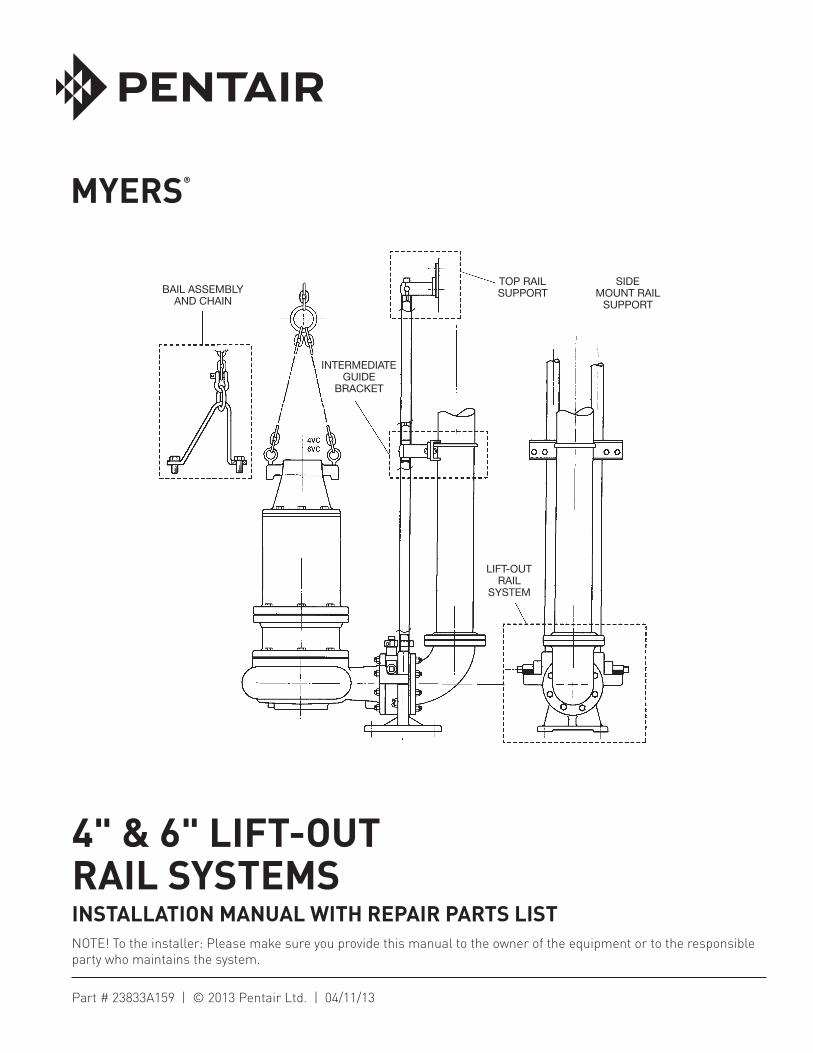
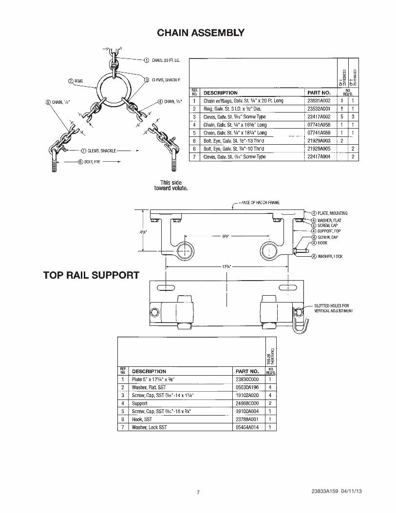
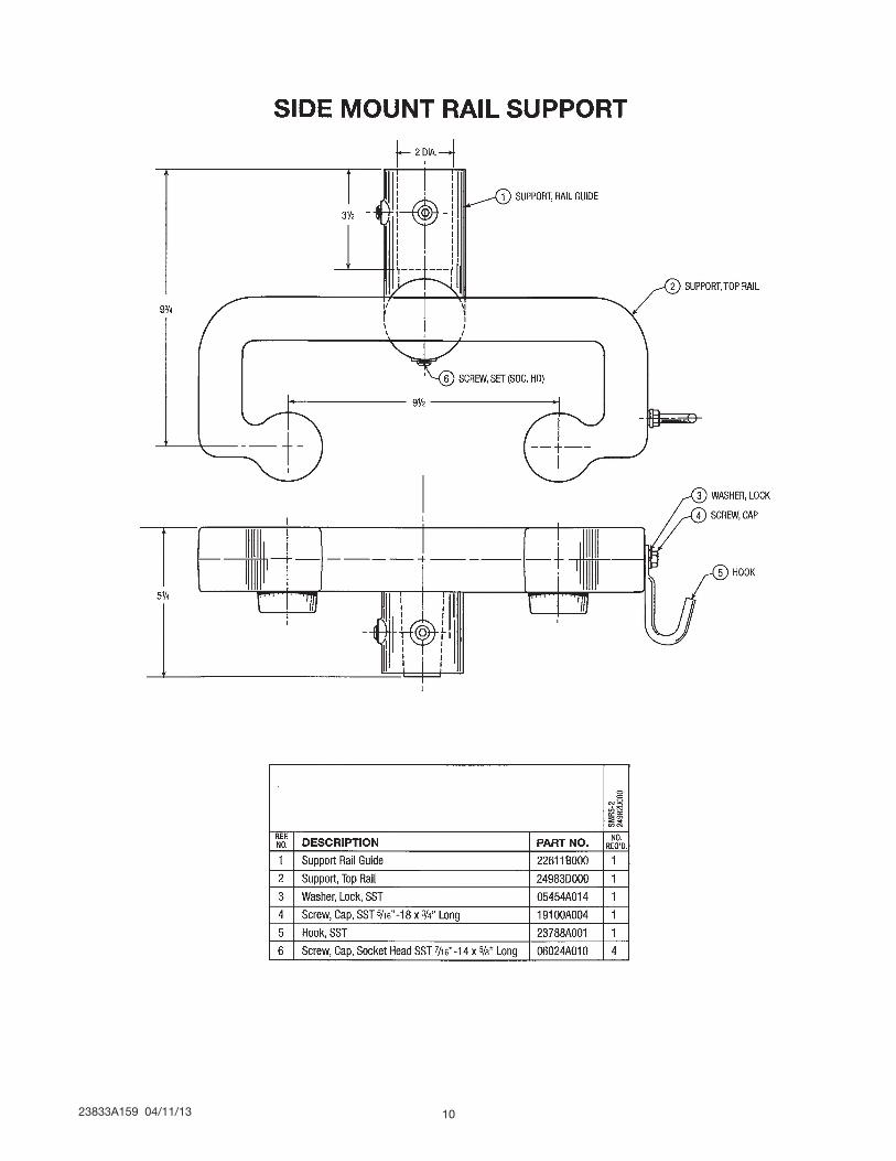
TOP RAIL SUPPORT
SIDE MOUNT RAIL
SUPPORT
LIFT-OUT RAIL
SYSTEM
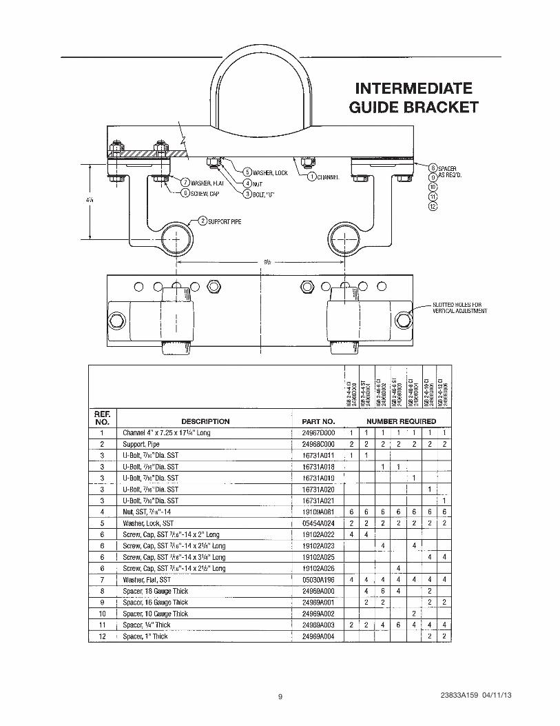
INTERMEDIATE GUIDE
BRACKET
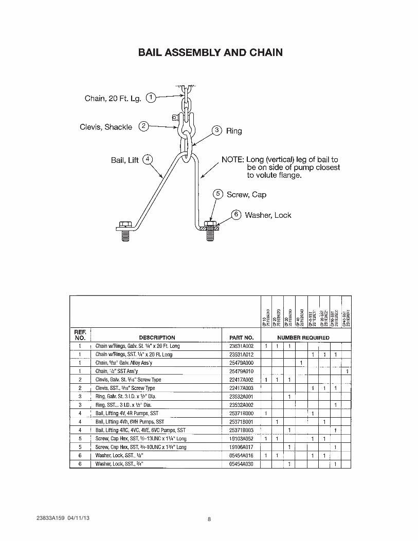
BAIL ASSEMBLY AND CHAIN
NOTE! To the installer: Please make sure you provide this manual to the owner of the equip ment or to the responsible party who maintains the system.
4" & 6" LIFT-OUT RAIL SYSTEMSINSTALLATION MANUAL WITH REPAIR PARTS LIST
Part # 23833A159 | © 2013 Pentair Ltd. | 04/11/13
23833A159 04/11/13 2
CAUTION!
After the pump is installed and sewage has entered the basin, there is DANGER. Sewage water gives off methane and hydrogen sulfide gases which are poisonous. Never enter a wet well unless proper confined space entry procedures are followed.
CALIFORNIA PROPOSITION 65 WARNING:
This product and related accessories contain chemicals known to the State of California to cause cancer, birth defects or other reproductive harm.
VALVES
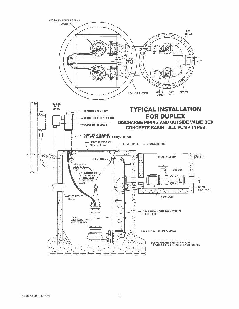
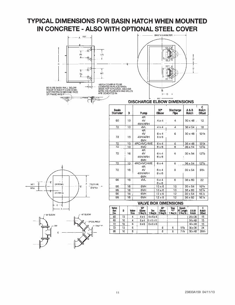
It is recommended that all check valves and shutoff valves be mounted outside the sump – in a valve box. See Typical drawing. Shut-off valves should be of the water works approved type with resilient rubber disk seat.
BASIN BOTTOM
All cement pipe basins must have a smooth, level troweled bottom for level mounting of discharge casting.
BASIN COVERS
Basin hatch type covers are made in either aluminum or steel and for mounting on a concrete basin top or on an aluminum or steel basin cover. When hatch cover is to be mounted on concrete top, it is generally poured in place with the concrete top. Pin lugs are provided to hold the cover in place. Bolts for mounting top rail support are screwed through the cover flange from the back side. This allows the bolts to be cemented in with basin top. All bolts are stainless steel and nuts are provided for securing the brackets. If other than Myers hatch covers are used, dimensions must be similar to the Myers hatch drawing shown. Cover should be drilled and tapped at dimensions shown, and stainless steel bolts installed for mounting top rail support guide brackets. When complete basin cover is steel or aluminum, the cover is secured to concrete basin wall with expansion bolts.
INSTALLING RAIL SYSTEM PARTSMounting Cover, Discharge Base and Rails
1. Set concrete cover with hatch opening in position.
2. Bolt top rail support plates, to hatch frame. Stainless steel bolts are screwed through frame angles when shipped and nuts are provided to hold the plate. Pipe supports have vertical slots so that they can be adjusted for final fit on rails. The plate has slots so the two plates in a duplex
system can be adjusted to obtain required center-to-center distance between pumps.
3. Lower the base or base/elbow assembly into the basin.
4. Position the base elbow assembly by dropping a plumb line from center of pipe supports, located on top rail support plate, to center of tapered pins protruding from the top of the base elbow assembly. Level the elbow flange in two directions, 90° to each other. Shims may be required under the base in order to obtain this level condition. Mark the position of the base hold-down bolts through the holes in the base.
5. Move the base aside to allow drilling the concrete for 3/4" expansion bolts, 2-1/2" long. Move the base over the bolt holes and recheck with level and plumb line. Install expansion bolts.
6. Cut the pipe guide rails to the proper length and install them between the pipe supports at the top of the basin and the pins on the base. Guide rails are schedule 40 galvanized or stainless steel.
7. Install discharge pipe as required by the particular job specifications. If one larger size discharge pipe is required, such as 6" pipe on a 4" pump, a reducing elbow can be provided. IMPORTANT: DISCHARGE PIPE AND GUIDE RAILS MUST BE PARALLEL IF INTERMEDIATE GUIDE BRACKET IS USED.
8. If the top rail support plate cannot be attached to the top hatch cover frame, a special rail bracket, can be furnished for mounting directly to a pipe cemented in the basin wall. This bracket is set and aligned with discharge base the same as described for the rail guide plate attached to the frame.
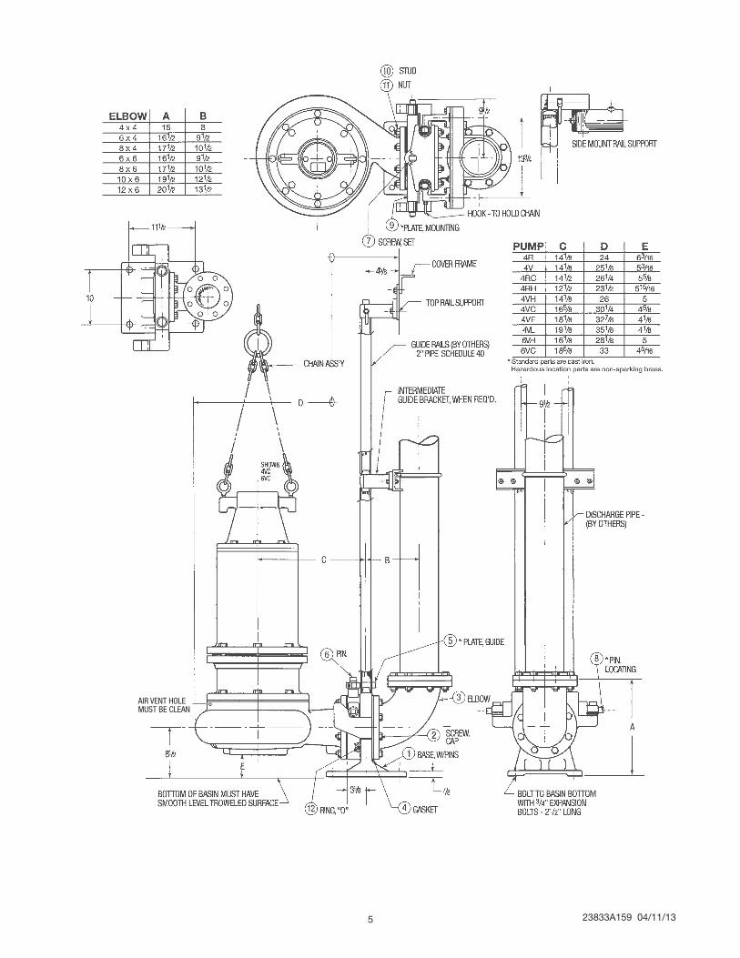
INSTALLING INTERMEDIATE GUIDE BRACKET
GUIDE RAIL LENGTH IGB REQUIRED 21 Ft. or less 0 21 Ft. to 40 Ft. 1 Over 40 Ft. 2
1. Remove guide rails, and cut a piece from each one. These pipes must be exactly the same length and of a length that will permit installing the intermediate guide bracket in the desired location.
2. Place the cut pieces of pipe over the guide rail pins located in the base.
3. Set the intermediate guide bracket in position with tapered guides into pipes. Put U-bolt around discharge pipe and tighten lightly.
4. Measure from joint on tapered plug in intermediate guide bracket to joint of tapered plug on top rail support and cut two rails to this length. Put rails in place and tighten screws in top rail support. Holes are slotted to adjust for any error in rail pipe length.
5. Recheck rails; they must be straight and plumb. Move intermediate guide bracket if necessary
23833A159 04/11/133
to perfectly align rails. Spacers may be added or removed from the intermediate guide bracket to obtain alignment. After alignment is secured, tighten nuts on U-bolt.
6. If a second intermediate guide bracket is used, the above procedure is followed for installation.
Attaching Mounting Plate to Pump
1. With a gasket between the mounting plate and pump discharge, attach the mounting plate with the studs and nuts supplied. The mounting plate should be turned so that two pins are horizontal and one pin vertical – pointing up.
Installing Pump and Mounting Plate
1. Check pump rotation if 3 phase. Connect power cords to pump control panel and lay pump on its side so impeller can be seen. Turn all switches to Off position.
2. Close main circuit breaker, then jog manual switch to On and then Off. Note rotation of impeller. Impeller must turn counterclockwise when looking into the inlet of the impeller. If rotation is wrong, interchange any two line leads to the motor. BE SURE MAIN BREAKER IS OFF WHEN THIS CHANGE IS MADE. MARK WIRES SO THEY CAN BE REPLACED IN THE SAME ORDER.
3. Attach lifting chains to pump. This is done by installing to eye bolts provided with lifting chain. The short leg of chain is installed on discharge flange side of pump.
WARNING! Do not exceed working load limit of chains and other lifting devices. Do not use chains or lifting devices where failure could result in loss of life. Examine chains and lifting devices for deformation or damage before and after each lift.
4. A hook is located on the top rail support, to hold the upper end of the chain when not in use.
5. Mount the guide plate, on the vertical pin of the mounting plate. Vertical pin should not be tight; it should be permitted to turn about 1/2 turn. Tighten the two set screws.
6. Position the pump so the guide rails relocated in the slots of the guide plate. Slowly lower the pump down the guide rails to the base. Lower the pumps until the locating pins (horizontal pins on the mounting plate) seat on the inclined surface of arms on the base.
7. The pump is now properly positioned for operation.
FLOAT SWITCH INSTALLATION 1. Level controls are held by support bracket and
cords are adjusted for proper depth.
a. Lower turn-off control should be set so that pump stops when water level is about at the top of the volute.
b. First turn-on control is set to start pump when level is at height specified above pump.
c. Second turn-on control of a duplex pump system is set at height specified above first turn-on control.
d. Alarm control is set about 6" to 12" above the highest turn-on control.
e. No control should be set above basin inlet invert or in front of inlet.
f. Pump is now completely operational.
AIR VENTING
Air tends to trap in the pump volute when water rises in the sump or when the pump is lowered into water after service. To vent off this air, a small hole is drilled into the pump volute. BE SURE THIS VENT HOLE IS CLEAN AFTER ANY SERVICE WORK ON PUMP. Air venting is not a problem after initial start.
23833A159 04/11/13 4
23833A159 04/11/135
AIR VENT HOLEMUST BE CLEAN
23833A159 04/11/13 6
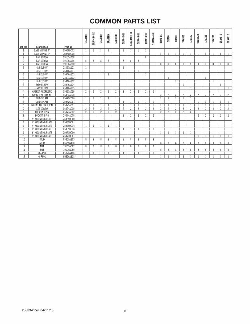
Ref. No. Description Part No.
SRA4
4HH
SRA4
4HH-
LE
SRA4
6HH
SRA4
8HH
SRAM
4HH
SRAX
44HH
SRAX
44HH
-LE
SRAX
46HH
SRAX
48HH
SRAM
X44H
H
SRA6
-LE
SRA6
6
SRA6
8
SRA6
10
SRA6
12
SRA6
X-LE
SRAX
66
SRAX
68
SRAX
610
SRAX
612
1 BASE W/PINS 4" 25068D002 1 1 1 1 1 1 1 11 BASE W/PINS 6" 25070D000 1 1 1 1 1 1 1 1 1 12 CAP SCREW 19105A038 82 CAP SCREW 19105A036 8 8 8 8 8 8 82 CAP SCREW 19106A018 8 8 8 8 8 8 8 8 8 83 4x4 ELBOW 23497A101 1 13 4x6 ELBOW 25046A101 1 13 4x8 ELBOW 25046A103 1 13 6x6 ELBOW 23497A102 1 13 6x8 ELBOW 25046A102 1 13 6x10 ELBOW 25046A104 1 13 6x12 ELBOW 25046A105 1 14 GASKET, NEOPRENE 05863A019 2 2 2 2 2 2 2 2 2 24 GASKET, NEOPRENE 05863A020 2 2 2 2 2 2 2 2 2 25 GUIDE PLATE 25072C000 1 1 1 1 1 1 1 1 1 15 GUIDE PLATE 25072C001 1 1 1 1 1 1 1 1 1 16 MOUNTING PLATE PIN 25073A001 1 1 1 1 1 1 1 1 1 1 1 1 1 1 1 1 1 1 1 17 SET SCREW 06024A010 2 2 2 2 2 2 2 2 2 2 2 2 2 2 2 2 2 2 2 28 LOCATING PIN 25073A002 2 2 2 2 2 2 2 2 2 28 LOCATING PIN 25074A000 2 2 2 2 2 2 2 2 2 29 4" MOUNTING PLATE 25069D0009 4" MOUNTING PLATE 25069D0019 4" MOUNTING PLATE 25069D014 1 1 1 1 19 4" MOUNTING PLATE 25069D016 1 1 1 1 19 6" MOUNTING PLATE 25071D000 1 1 1 1 19 6" MOUNTING PLATE 25071D001 1 1 1 1 110 STUD 05659A103 8 8 8 8 8 8 8 8 8 810 STUD 05659A110 8 8 8 8 8 8 8 8 8 811 NUT 19109A082 8 8 8 8 8 8 8 8 8 811 NUT 19109A080 8 8 8 8 8 8 8 8 8 812 O-RING 05876A126 1 1 1 1 1 1 1 1 1 112 O-RING 05876A128 1 1 1 1 1 1 1 1 1 1
COMMON PARTS LIST
23833A159 04/11/137
23833A159 04/11/13 8
23833A159 04/11/139
23833A159 04/11/13 10
23833A159 04/11/1311
6 x 6 x 6

1101 MYERS PARKWAY 490 PinEbuSh RoAd, unit #4 AShLAnd, ohio, uSA 44805 CAMbRidGE, ontARio, CAnAdA n1t 0A5 419-289-1144 800-363-PuMP
WWW.FEMYERS.CoM
Warranty Rev. 12/13
STANDARD LIMITED WARRANTY
Pentair Myers® warrants its products against defects in material and workmanship for a period of 12 months from the date of shipment from Pentair Myers or 18 months from the manufacturing date, whichever occurs first – provided that such products are used in compliance with the requirements of the Pentair Myers catalog and technical manuals for use in pumping raw sewage, municipal wastewater or similar, abrasive-free, noncorrosive liquids.
during the warranty period and subject to the conditions set forth, Pentair Myers, at its discretion, will repair or replace to the original user, the parts that prove defective in materials and workmanship. Pentair Myers reserves the right to change or improve its products or any portions thereof without being obligated to provide such a change or improvement for prior sold and/or shipped units.
Start-up reports and electrical schematics may be required to support warranty claims. Submit at the time of start- up through the Pentair Myers website: http://forms.pentairliterature.com/startupform/startupform.asp?type=m. Warranty is effective only if Pentair Myers authorized control panels are used. All seal fail and heat sensing devices must be hooked up, functional and monitored or this warranty will be void. Pentair Myers will cover only the lower seal and labor thereof for all dual seal pumps. under no circumstance will Pentair Myers be responsible for the cost of field labor, travel expenses, rented equipment, removal/reinstallation costs or freight expenses to and from the factory or an authorized Pentair Myers service facility.
this limited warranty will not apply: (a) to defects or malfunctions resulting from failure to properly install, operate or maintain the unit in accordance with the printed instructions provided; (b) to failures resulting from abuse, accident or negligence; (c) to normal maintenance services and parts used in connection with such service; (d) to units that are not installed in accordance with applicable local codes, ordinances and good trade practices; (e) if the unit is moved from its original installation location; (f) if unit is used for purposes other than for what it is designed and manufactured; (g) to any unit that has been repaired or altered by anyone other than Pentair Myers or an authorized Pentair Myers service provider; (h) to any unit that has been repaired using non factory specified/oEM parts.
Warranty Exclusions: PEntAiR MYERS MAKES no EXPRESS oR iMPLiEd WARRAntiES thAt EXtEnd bEYond thE dESCRiPtion on thE FACE hEREoF. PEntAiR MYERS SPECiFiCALLY diSCLAiMS thE iMPLiEd WARRAntiES oF MERChAntAbiLitY And FitnESS FoR AnY PARtiCuLAR PuRPoSE.
Liability Limitation: in no EVEnt ShALL PEntAiR MYERS bE LiAbLE oR RESPonSibLE FoR ConSEQuEntiAL, inCidEntAL oR SPECiAL dAMAGES RESuLtinG FRoM oR RELAtEd in AnY MAnnER to AnY PEntAiR MYERS PRoduCt oR PARtS thEREoF. PERSonAL inJuRY And/oR PRoPERtY dAMAGE MAY RESuLt FRoM iMPRoPER inStALLAtion. PEntAiR MYERS diSCLAiMS ALL LiAbiLitY, inCLudinG LiAbiLitY undER thiS WARRAntY, FoR iMPRoPER inStALLAtion. PEntAiR MYERS RECoMMEndS inStALLAtion bY PRoFESSionALS.
Some states do not permit some or all of the above warranty limitations or the exclusion or limitation of incidental or consequential damages and therefore such limitations may not apply to you. no warranties or representations at any time made by any representatives of Pentair Myers shall vary or expand the provision hereof.