Embed Size (px)
Citation preview

Published by R&D OceAlmadar Aljadid Co. Libya www.almadar.ly
July 2014, Vol. 01, No. 01
Cognitive RadioPromising Technology for the Congested Spectrum
ISSN 2313- 156X
Almadar Journal for Communications, Information Technology, and Applications

Almadar Journal for Communications, InformationTechnology, and Applications
Vol. 01, No. 01, July 2014
AJCITA
Almadar Journal for Communications, Information Tech-nology, and Applications (AJCITA) (ISSN 2313−156X),(Local registration number at the Libyan National Li-brary 369/2014) is published semi-annually by the Researchand Development Office, Almadar Aljadid Co. Address:Gurji−Tripoli−Libya, P.O.Box 83792, +218 91 919 0500, Ext.3520, [email protected], www.almadar.ly.
AJCITA aims to provide high-level scientific papers withvalue in academic research and industry. The published paperscan be:
• Original research articles with clear contributions,• Review articles,• Application articles with industrial values,• Invited articles.
DIRECTOR OF JOURNAL
Abdulla A. Abouda, Manger of Research and De-velopment Office, Almadar Aljadid Co. Libya, Email:[email protected]
EDITOR IN CHIEF
Mohammed S. Elmusrati, Professor and Head of Communi-cations and Systems Engineering Group, University of Vaasa,Finland. He is also Professor at Electrical and Electronic En-gineering Department, University of Benghazi, Libya, Email:[email protected]
EDITORIAL BOARD
Mohamed G. El−Tarhuni, Professor and Head of ElectricalEngineering Department, American University of Sharjah,United Arab Emirates, Email: [email protected] A. Ganoun, Assistant Professor at Electrical and Elec-tronic Engineering Department, University of Tripoli, Libya,Email: [email protected] A. Ashibani, Associate Professor at Electrical andElectronic Engineering Department, Collage of IndustrialTechnology, Libya, Email: [email protected] M. Elammari, Associate Professor and Head ofSoftware Engineering Department, University of Benghazi,Libya, Email: [email protected] A. Akki, Professor at Electrical and ElectronicEngineering Department, University of Tripoli, Libya, Email:[email protected]
PUBLICATION STAFF
Asmaiel A. AhteebahAhmed A. Aljarray
REVIEWERS OF THIS ISSUE
Rajab LegnainNaser El−TarhuniAbdulla AboudaMohammed ElfituriDuan RuifengOmar Abu-EllaTarek SheltamiMohamed El−TarhuniMohammed Elmusrati
COVER PAGE DESIGN
Abdulnaser E. ElsousiAbdulla I. Aborwies
SUBMISSIONS
The journal welcomes submissions of original research workin the area of telecommunications, information technology andapplications. Articles both in English and Arabic languageare welcomed. A 500 LYD is granted for accepted papers.Best paper award every year will be granted 5000 LYD. Allcommunications between editorial board and correspondentauthors will be through [email protected]. The submittedpapers will be checked first by the editors to confirm thatit follows the main journal requirements in terms of topicsand style. If the paper passed the first check it will be sent toat least three independent peer reviewers to give acceptancestatement about the paper. The reviewers’ identities will bemasked from the authors.
ADVERTISING
Advertising in AJCITA is accepted at the discretion of thepublisher. In the next couple of issues accepted advertisementwill be published free of charge. All communications relatedto advertising should be directed to [email protected].
COPYRIGHT
All rights reserved for AJCITA, however, abstracting is per-mitted with credit to the source and libraries are permitted tophotocopy. AJCITA is not responsible for opinions presentedin its publication, they represent the views of the individuals.

Almadar Journal for Communications, InformationTechnology, and Applications
Vol. 01, No. 01, July 2014Contents
Editorial Page: Mobile Networks: The Platform for Smart Connected WorldMohammed S. Elmusrati, Page 1.
The Future of WCDMA/HSPA: Delivering Exceptional MBB User Experience EverywhereWhite Paper from Ericsson, Page 2.
Cognitive Radio−An OverviewMonirosharieh Vameghestahbanati and Mohamed El−Tarhuni, Invited Paper, Page 7.
Power Allocation for Cognitive Radios: A SurveyRuifeng Duan, Mohammed S. Elmusrati, and Reino Virrankoski, Page 13.
On Effective Capacity of Cognitive Radios with TAS and MRCRuifeng Duan and Mohammed S. Elmusrati, Page 25.
Interference Mitigation Using Optimal Successive Group Decoding for Interference ChannelsOmar Abu−Ella and Mohammed S. Elmusrati, Page 37.
Advertisments in Arabic
Libyan Innovation Prize 2014 by National Authority for Research, Science, and Technology.
Introduction to Research and Development Office at Almadar Aljadid Co. Libya.
Introduction to Almadar Journal for Communications, Information Technology, and Applications, theArabic version.


1
EDITORIAL PAGEMobile Networks: The Platform for Smart Connected World
Mohmmed S. Elmusrati1
MOBILE networks have expanded dramatically in alldimensions during the last two decades. Based on pre-
diction studies carried out by CISCO, the growth of requiredwireless data rate will increase by more than 11 fold (1100%)between 2013 and 2018. In this year 2014, the number ofInternet accounts over cellular networks has passed 7.2 billionconnections, meaning that there are more device connectionsthan people on Earth!. This refers to the fact that average userhas more than one device connected to Internet networks. Thisindicates the starting of the era of Internet of Things (IoT).IoT includes countless applications beside the conventionalVoIP and Internet applications. Some applications are in fieldsof security, smart cities, machine-to-machine, automations, e-government, smart homes, remote monitoring and control, andsafety applications. According to ABI Research, more than30 billion devices will be wirelessly connected to the Internetbackbone by 2020.
The recent surprised improvements in the performance andreliability of wireless communication technologies motivatethe majority of Internet and IP traffics to use wireless as thefirst hop. Hence, fast and reliable wireless networks becomevery critical requirement for the growing Internet and IPapplication demands.
At abstract level we have wireless communication platformto transfer information signal (voice, video, sensor signal, datafrom certain machine, etc.) from one location to another. Infor-mation Technology (IT) may create several new applicationsto utilize this communication platform for the sake of higherquality of life as well as higher safety and security.
Beside the opportunities of wireless networks and appli-cations, there are many challenges as well. The challengesare everywhere in the wireless communication, IT, and theapplications. Therefore, we have this journal to discuss ideas,analyze problems, propose solutions, suggest applications, and
1 Mohammed S. Elmusrati is a full Professor and Head of Communicationand Systems Engineering Group, University of Vaasa - Finland (On Leave).He is also Professor with Electrical and Electronic Engineering Department -University of Benghazi - Libya (email: [email protected]).
enrich the scientific society of wireless communication and IT.One of the major challenges of wireless communication is
the acute shortage (scarcity) in the spectrum. The whole usefulspectrum (except small ISM bands) has been already licensedfor specific applications. Therefore, it becomes a problem todefine new services or to increase the communication capacity(which is linearly related to the bandwidth). Several noveltechnologies have been developed during the last two decadesto overcome such problems. One method is based on therecycling of licensed bands at the condition that no harmfulinterference could be allowed for the primary user. This isknown as cognitive radio. One invited paper in this regard ispresented in this issue. The paper is titled “Cognitive Radio:An Overview” by M. Vameghestahbanati and M. El-Tarhuni.This invited paper presents a quite general background aboutthe topic. Moreover, two more specific technical papers inthe area of cognitive radios are presented in this issue aswell. The first paper is titled “Power Allocation for CognitiveRadios: A Survey”. This paper gives an important surveyfor the power allocation techniques in cognitive radios. Itis clear that transmit power is the critical parameter forsuccessful cognitive radio system. The second paper in thearea of cognitive radio is titled “On Effective Capacity ofCognitive Radio with TAS and MRC”. This paper presentsnovel analysis of the effective capacity of cognitive radiowith multiple transmit antennas and using transmit antennasselection scheme with MRC.
Another method to overcome the problem of limited spec-trum is by increasing the spectrum efficiency. This can beachieved with different techniques such as MIMO antennas,interference management, global radio resources scheduling,and multiuser detection methods. One important contributionin the area of joint multiuser detection is presented in this is-sue. The paper is titled “Interference Mitigation Using OptimalSuccessive Group Decoding for Interference Channels”.
Beside one invited paper and three peer reviewed papers,we have also one white paper submitted by Ericsson Co.Ericsson’s white paper discusses the future of WCDMA/HSPAas powerful technology for providing mobile broadband duringthe current decade.
Finally we would like to thank all authors for submittingtheir great contributions to the first issue of AJCITA. Further-more we are thankful for the reviewers for their great efforts toreview papers and give important comments and corrections.

2 ALMADAR JOURNAL FOR COMMUNICATIONS, INFORMATION TECHNOLOGY, AND APPLICATIONS, VOL. 01, NO. 01, JULY 2014
The Future of WCDMA/HSPA: DeliveringExceptional MBB User Experience Everywhere
(White Paper from Ericsson1)
Abstract—WCDMA/HSPA enables hundreds of millions ofpeople to access mobile broadband (MBB) through their smart-phones every day. Today, new, low-priced WCDMA/HSPA smart-phones are entering the market, and they will enable MBBfor new hundreds-of-millions-sized markets. WCDMA/HSPA hasevolved into a highly effective MBB technology that will continueto serve both new and traditional markets for years to come, ei-ther as the main MBB technology or as an important complementto LTE.
I. ESSENTIAL TODAY AND TOMORROW
THe number of mobile broadband (MBB) subscribers andthe level of traffic continue to grow at an unprecedented
pace. The key driver behind this growth is an accelerating shiftfrom voice-centric phones and feature phones to increasinglyaffordable MBB-enabled smartphones. In some markets, asmany as 90 percent of all new handset sales are accounted forby MBB enabled smartphones. While this figure varies acrossmarkets with different levels of maturity and consumer buyingpower, the global trend is clear as illustrated in Figure 1. Andit is being driven first and foremost by the falling price ofhighly capable WCDMA/HSPA smartphones.
This transition to smartphones presents a significant newrevenue opportunity for operators, as experience shows thereis substantially higher average revenue per user (ARPU) fromsmartphone users compared with non-smartphone users.
WCDMA/HSPA networks will have an essential role toplay in enabling operators to take advantages of this marketopportunity, both today and for the foreseeable future. This isdriven by mobile operators’ need to satisfy four fundamentalmarket requirements, wherever they are in the world andwhatever the stage of market development. These marketrequirements are:
• Serving the growing volumes of affordable MBB-capableWCDMA/HSPA smartphones that are arriving on themarket.
• Ensuring a “megabit experience”, better than 1Mbpsdownload speed, for all MBB subscribers, and a“superior-”MBB experience, better than 2Mbps downloadspeed, typically 10Mbps, for high-end-device users wher-ever they go.
• Delivering high-quality voice services everywhere.• Meeting the roaming needs of all MBB subscribers
around the world.
1This article is a white paper from Ericsson, provide to Almadar Journalfor Communications, Information Technology, and Applications by PaoloLamberti. (emails: [email protected]).
Fig. 1. The rise of smartphones, mobile PCs, mobile routers and tabletsubscriptions with a cellular connection, 2009-2018 [1].
As with most consumer electronics technology, smartphonesare subject to Moore’s Law. In simple terms, smartphones areroughly doubling their performance. For example, processingpower and data speeds, while halving in cost, every two years.We have reached a stage where the cost of WCDMA/HSPAchipsets is bringing highly capable smartphones into the pricebracket previously occupied only by voice-centric and featurephones. At such sub-USD 100 prices, smartphones appear tohave reached a tipping point and are entering a true mass-market phase.
While the rollout of 4G LTE radio networks is proceed-ing rapidly, especially in developed markets, coverage isstill only a fraction of that provided by GSM/EDGE andWCDMA/HSPA and, from a global perspective, will be formany years to come. Operators need to ensure that 4G sub-scribers MBB experience does not “fall off a cliff” wheneverthey leave LTE coverage. MBB subscribers will always wantgood-quality voice services. WCDMA/HSPA offers a well-proven and efficient voice solution that meets very good KPIs,including voice retainability and voice accessibility. It is alsoable to provide HD voice quality, which is already beingdeployed by several operators.
LTE is being deployed in more than 20 radio bands aroundthe world, unlike WCDMA/ HSPA, which has only four mainbands worldwide. It will take time before one single LTEsmartphone will be able to operate on every LTE networkaround the world. In addition, some markets are still yearsaway from awarding LTE licenses. Nonetheless, operators

ALMADAR JOURNAL FOR COMMUNICATIONS, INFORMATION TECHNOLOGY, AND APPLICATIONS, VOL. 01, NO. 01, JULY 2014 3
Fig. 2. Fixed and mobile subscription growth 2009-2018 [1].
need to ensure that high-value roaming subscribers can enjoya consistent MBB experience.
While LTE is often viewed as the key solution for handlinghigh-capacity situations, WCDMA/HSPA is equally capable ofhandling large numbers of smartphone users. What is more,this capability is being dramatically extended over the comingyears, mainly through the implementation of software features.
Fundamentally, all operators whether they are voice-centricGSM operators or MBB-centric operators who are deployingLTE will benefit from having a strong WCDMA/HSPA net-work, as HSPA is the only technology that will be used in allsmartphones for the foreseeable future.
Operators deploying LTE in the same frequency bandin which they already offer HSPA will benefit fromWCDMA/HSPA functionality that allows effective spectrumrefarming.
II. THE HIGH-GROWTH MARKET
In the past couple of years, MBB has become firmlyestablished as people have grown accustomed to having high-speed-internet access wherever they go. According to marketanalyst firm Wireless Intelligence [2], MBB technologies nowaccount for about one-quarter of total global connections.WCDMA/HSPA makes up the vast majority of MBB con-nections and is the fastest-growing wireless technology so far.
Now MBB is entering its next phase of expansion asthe availability and affordability of devices grows, especiallyin developing markets. Ericsson’s estimates show that therewere 6.6 billion mobile subscriptions (excluding machine-to-machine subscriptions) at the end of 2012 [1]. Of these, about1.5 billion were MBB subscriptions (including feature phones,smartphones, mobile PCs, tablets, mobile routers and dongles).
According to Wireless Intelligence, mobile subscriptions inthe developing world passed the 5 billion mark in the thirdquarter of 2012, and now comprise almost 80 percent of theworld’s total. By the end of 2018, total mobile subscriptionsare expected to grow to 9.3 billion, and about 6.5 billion ofthese will be for MBB, as shown in Figure 2.
Fig. 3. Global smartphone sales forecast by wholesale price tier. Smart-phones below USD 190 are the biggest contributor to volume increases(source:Strategy Analytics) [5].
A. Enter the affordable smartphone
At the centre of this more than fourfold predicted increase inMBB subscriptions is the rising tide of affordable smartphonesand, to a lesser extent, tablets. According to the market analystfirm Strategy Analytics [3], [4], 217 million smartphones weresold in the fourth quarter of 2012 some 40 percent more thanin the same quarter of 2011 overall. Within this figure, sales ofAndroid smartphones grew close to 90 percent year-on-year.And there is a similar story for tablets: fourth-quarter 2012sales were 45 million; 67 percent higher year-on-year overalland 85 percent higher year-on-year for Android devices. Theoverall growth trend is set to continue. Total smartphonesubscriptions are set to rise from 1.1 billion at the end of2012 to about 3.3 billion in 2018. One of the most significantfactors behind this rapid growth in smartphone adoption willbe their significantly lower average selling price, driven bythe availability of lower-cost chipsets, especially from Asianmanufacturers.
We are already starting to see a number of sub-USD100 WCDMA/HSPA smartphones with 14.4Mbps, dual-band,dual-core processor capabilities. There is also strong growthin the midrange smartphone market (USD 100-200), thanksto the arrival of much lower-cost chipsets for 42Mbps, quad-core, HD (1280x720) devices. According to market researchfirm Strategy Analytics [5], unit sales of entry and mid-rangesmartphones are set to grow at a compound annual rate of 45percent between 2011 and 2016, while unit sales of premiumand high-end smartphones will grow by a compound rate ofjust 1.8 percent, as illustrated in Figure 3.
This increase in entry and mid-range smartphones willpower demand for MBB coverage, capacity and throughput,especially in developing markets, where mobile devices willprovide many people’s first taste of high-speed internet con-nectivity. So, which networks will this growing band of MBBsubscribers be using?.

4 ALMADAR JOURNAL FOR COMMUNICATIONS, INFORMATION TECHNOLOGY, AND APPLICATIONS, VOL. 01, NO. 01, JULY 2014
Fig. 4. Mobile subscription growth by technology [1].
B. WCDMA/HSPA scale beats LTE pace
In the second half of 2012, there was extremely rapid growthin LTE connections, mainly driven by smartphone uptakein Japan, South Korea and the US. LTE subscriptions areexpected to grow from just under 100 million at the end of2012 to about 1.6 billion by the end of 2018. However, overthe same period, WCDMA/HSPA subscriptions are predictedto grow from just over 1 billion to 4.4 billion, as shown inFigure 4 [1]. In other words, there are likely to be almostthree times as many WCDMA/HSPA subscriptions as LTEsubscriptions in 2018. It is also worth noting that GSM/EDGEsubscriptions have continued to grow in number, and areonly expected to start declining during 2013. In addition,Ericsson’s predictions forecast that global population coveragefor WCDMA/HSPA will increase from 50 percent in 2012to more than 85 percent in 2017. Furthermore, people areexpected to be using their MBB devices a lot more than today.They will consume roughly four times as much data across alldevice types by 2018, as shown in Figure 5. For example, theaverage monthly data usage for a smartphone is expected torise from 450MB in 2012 to nearly 2GB in 2018 [1].Whichever way we look at the numbers relating to MBB,it is clear that it is a high-growth market that offers greatpotential for revenue growth in developed and developingmarkets. What is also clear is that WCDMA/HSPA is goingto be the MBB workhorse for some years to come. Whetheror not mobile operators have access to LTE spectrum, theywill need to ensure the availability and good performanceof WCDMA/HSPA networks in order to serve the rapidlygrowing numbers of non-LTE smartphones and other devices.Even if they are rolling out LTE, operators need to ensuretheir WCDMA/HSPA networks provide a comparable qualityexperience when users move outside LTE coverage. As de-mand grows, MBB services are putting immense pressure onlimited radio spectrum, and operators will need to find newways of using this spectrum ever more efficiently across 2G,3G and 4G technologies. So, how can operators ensure theyhave the WCDMA/HSPA coverage, capacity, performance andbusiness models they need to meet the rapid increases in MBBuptake, usage and expectations?.
Fig. 5. How average monthly mobile-data usage will grow for mobile PCs,tablets and smartphones [1]
III. DELIVERING MORE
Whether operators are expanding their WCDMA/HSPAcoverage into new areas, or upgrading WCDMA/HSPA cov-erage and capacity as a complement to LTE rollout, the keychallenges are the same:
• Delivering cost-efficient WCDMA/HSPA coverage.• Efficiently handling very high numbers of smartphones,
characterized by a mix of voice and very bursty datatraffic.
• Ensuring a consistent user experience with the focus onKPIs, such as call retainability and accessibility, as wellas high uplink and downlink throughput and short latency.Such KPIs will, to a large extent, define the perceptionof the operator among smartphone users.
• Constantly monitoring the smartphone population andtaking action to shape it, for example, by using subsidiesto encourage users to replace their old network-inefficientsmartphones with newer models that enhance both net-work efficiency and user experience.
Unlike any other radio technology, WCDMA/HSPA is botha proven voice solution and also a very capable MBB solutionthat can deliver very high peak rates in the uplink anddownlink, as well as high cell-edge throughput. Cell-edgethroughput has a dominant influence over the WCDMA/ HSPAsystem’s smartphone capacity.
WCDMA has already gone through a lengthy process ofevolution, and has come a long way from its first Release 99incarnation more than a decade ago. WCDMA/HSPA alreadyexceeds the requirement to deliver a megabit experience forusers everywhere, thanks to:
• Support for up to 42Mbps in the downlink and 5.8Mbpsin the uplink.
• Superior radio performance with a comprehensive basestation portfolio for optimized coverage and capacity.
• Excellent in-service performance built on scalable andfuture-proof 3G platforms.
• A clear evolution path to HSPA Evolution, which willprovide speeds of more than 84Mbps in the downlinkand more than 12Mbps in the uplink.
Behind these headline features, there are numerous improve-ments being developed and applied to WCDMA/HSPA thatwill further boost its ability to deliver a better user experience

ALMADAR JOURNAL FOR COMMUNICATIONS, INFORMATION TECHNOLOGY, AND APPLICATIONS, VOL. 01, NO. 01, JULY 2014 5
through improved smartphone capacity and higher uplink anddownlink bit rates.
Many newer smartphones on the market support featuresthat enable a substantial rise in overall smartphone capacity(number of users per cell). For instance, multicarrier tech-nology enables the WCDMA/HSPA system to use multiple5MHz carriers for one user in both the uplink and downlink.From 3GPP Release 10 onwards, WCDMA/HSPA supportsmulticarrier operation on up to four carriers in the downlink(which can be spread across one or two frequency bands) andup to two carriers in the uplink. Multicarrier technology pro-vides both substantial capacity gains, as well as throughput andpeak rate gains in the cell. The first step in WCDMA/HSPAmulticarrier development (2x5MHz downlink) is available insmartphones today. Multicarrier in the uplink is expected toarrive in smartphones toward the end of 2013.
Another function that boosts capacity is the 3GPP-specifiedFast Dormancy Release 8. This enables a smartphone tomove to an energy-efficient state (Universal Terrestrial Ra-dio Access Network (UTRAN) Registration Area ForwardAccess Channel (URA_FACH)) as soon as it has no datato send, dramatically decreasing the time the smartphone isin the most resource-intensive state (Cell Dedicated Channel(Cell_DCH)).
The WCDMA/HSPA radio uplink is non-orthogonal bynature, meaning that all users in a cell interfere with eachother on the radio interface. The most efficient way to counterthis interference is to eliminate unnecessary, or excessive,network chatter, such as control signalling. This is the purposeof a feature called Continuous Packet Connectivity (CPC),which has the effect of dramatically improving uplink capacityby limiting interference. Many commercially available smart-phones already use fast dormancy and growing numbers areappearing with CPC.
In addition, advances in base station signal processingprovide a clearer received uplink signal, which reduces thecell’s total interference while sustaining uplink quality. Four-way (instead of two-way) receive diversity further amplifiesthe positive effects of advanced uplink receivers.
WCDMA/HSPA enables users that are sending and receiv-ing only small bursts of data (as is typical with smartphonesmost of the time) to handle that data in a semi-active statecalled CELL_Forward Access Channel (CELL_FACH). Toenable even more efficient CELL_FACH operation, 3GPPhas specified High-Speed (HS)_FACH for the downlink andEnhanced Uplink (EUL)_FACH for the uplink. HS_FACH-enabled smartphones are already available and EUL_FACHcapable smartphones are expected during 2013.
A. Enhancing coverage
The ability to extend WCDMA/HSPA coverage efficientlyis vital to turning the proliferation of low-cost HSPA smart-phones into increased revenue from MBB services. One keyway of doing this is to re-farm the 900MHz spectrum fromGSM to WCDMA/HSPA. This spectrum typically gives a 6dBlink budget advantage over the 2100MHz spectrum, whichtranslates into substantial coverage advantages. According to
the Global mobile Suppliers Association (GSA), 57 commer-cial WCDMA 900MHz networks have been deployed in 39countries (as of December 2012) [6]. Other WCDMA/HSPAcoverage-enhancing measures include four-way receiver diver-sity (rather than two-way), lower speech rate for better voicecoverage, and the capability for improved scaling of controland traffic channels.
B. Adapting data plans to market needs
One important aspect of driving the uptake of MBB, andincreasing ARPU overall, is to ensure that data plans meetsubscriber needs, especially in markets where the ARPU hastraditionally been low. The MBB pricing models used inmore established markets may not be appropriate for manydeveloping markets where ARPU can be one-tenth that of adeveloped market, for example. With the trend to bring yourown device (BYO D) in many mature markets, there are sev-eral new plans that are designed to attract new user categories.Often, operations are run by a mobile virtual network operator(MVNO) to differentiate from the major (owner) brand. Theseofferings tend to be characterized by a distinct internet flavour,no operator subsidies for devices and less customer support.Such approaches have proved successful in mature marketsand have attracted new smartphone users.
Another trend in mature markets is “prepaid as postpaid”.Traditionally, before data buckets were introduced, postpaidcustomers often represented a higher ARPU group than pre-paid customers. Data buckets are often defined by a fixedtraffic amount for a fixed price, which has made the distinctionbetween prepaid and postpaid less important for operators.Bucket allowances are typically not exceeded, which providesincreased revenue opportunities for operators. With the in-creasing popularity of tablets in developed markets, opera-tors have an opportunity to monetize this trend by offeringattractive tethering add-ons and sharing plans. Several oper-ators have already successfully transformed their subscriberplans from traditional voice minutes and SMS volume-basedcharging to charging based on actual data use.
The increasing availability of low-priced smartphones willenable 2G/feature phone users to move to a highly capableWCDMA/HSPA smartphone next time they invest in a newdevice, for about the same price. As it is quite likely thatthe WCDMA/HSPA smartphone will be the main broadband-access device for many consumers, operators need to offerappropriate, affordable plans. One way to enable MBB onthese devices is to permit small payments such as pay-per-hour or pay-per-day. Further, some operators have developedplans that permit pay-per- (small) data volume, and here it isimportant that the consumer is given control of the actual data-traffic consumption. For instance, using the operator’s ownportal would not consume any of the data allowance, whileaccessing Facebook would. With consumers in control, overtime they may be more willing to pay for a data bucket forinternet access, resulting in increased operator revenue.
Yet another way to boost revenue is to allow consumerstime-limited free MBB access to any predefined internet ser-vices in return for being shown advertisements before access

6 ALMADAR JOURNAL FOR COMMUNICATIONS, INFORMATION TECHNOLOGY, AND APPLICATIONS, VOL. 01, NO. 01, JULY 2014
is granted. An example could be 30 minutes of free internetuse after a one-minute commercial.
IV. CONCLUSION
Whether or not operators are rolling out LTE 4G networks,they will need to focus their attention on the performanceof their WCDMA/HSPA networks if they are to deliver aconsistent, high-quality user experience throughout their cov-erage areas. Fundamentally, it is vital that network technologymatches the capabilities and cost of the devices subscribers arechoosing to use to access MBB services. For the foreseeablefuture, WCDMA/HSPA will be by far the biggest technol-ogy by subscription numbers and by population coverage.CDMA/HSPA already provides the backbone for most MBBservices, and is being continuously developed to efficientlydeliver a true broadband experience that is on a par with 4Gto any device, in any location. No other technology can makethat claim.
V. GLOSSARY
ARPU Average Revenue per UserBYOD Bring Your Own DeviceCELL_DCH Cell Dedicated ChannelCELL_FACH Cell Forward Access ChannelCPC Continuous Packet ConnectivityEUL_FACH Enhanced Uplink Forward Access ChannelGSA Global mobile Suppliers AssociationHS_FACH High-Speed Forward Access ChannelMBB mobile broadbandMVNO mobile virtual network operatorTD-SCDMA time division synchronous code division multiple accessURA_FACH UTRAN Registration Area Forward Access ChannelUTRAN Universal Terrestrial Radio Access Network
REFERENCES
[1] Ericsson Mobility Report, November 2012, available at: http://www.ericsson.com/ericsson-mobility-report
[2] Global cellular market trends and insights, Wireless Intelligence,Q4, 2012, available at: https://wirelessintelligence.com/analysis/2012/01/global-cellular-market-trends-andinsight-q4-2011/
[3] Android and Apple iOS Capture a Record 92 Percent Share ofGlobal Smartphone Shipments in Q4 2012, Strategy Analytics, January2013, available at: http://www.strategyanalytics.com/default.aspx?mod=reportabstractviewer&a0=8155
[4] Global Tablet OS Market Share: Q4 2012, Strategy Analytics, January2013, available at: http://www.strategyanalytics.com/default.aspx?mod=reportabstractviewer&a0=8147
[5] Global LTE Smartphone Shipments Will Reach 275 MillionUnits in 2013, Strategy Analytics press release, December 2012,available at: http://www.strategyanalytics.com/default.aspx?mod=pressreleaseviewer&a0=5310
[6] UMTS900 Global Status Report, Global mobile Suppliers Associa-tion, http://www.gsacom.com, November 2012, available at:http://www.gsacom.com/php/access.php4

ALMADAR JOURNAL FOR COMMUNICATIONS, INFORMATION TECHNOLOGY, AND APPLICATIONS, VOL. 01, NO. 01, JULY 2014 7
Cognitive Radio−An Overview(Invited Paper)
Monirosharieh Vameghestahbanati1 and Mohamed El-Tarhuni2
Abstract—There has been an increasing demand for highdata rate services, which necessitates the development of moreefficient schemes for using the scarce radio spectrum. Traditionalfrequency allocation schemes are static and, thus, not capableof accommodating the growing number of wireless users andservices. Hence, it is required to have some form of spectrumsharing between existing and new users of the radio spectrum.Cognitive Radio (CR) is a system that allows for sharing thespectrum among users, which offers a highly flexible alternativeto the traditional fixed frequency band assignment. In this paper,we survey the recent progress along with some issues related tocognitive radio technology.
I. INTRODUCTION TO COGNITIVE RADIO
THe emerging multimedia type applications have resultedin increasing the need for higher data rate services. On
the contrary, the precious natural frequency is limited andcannot fulfill all the requirements. Traditionally, radio channelsare assigned to specific users who have a license for theexclusive use of that channel to avoid interference and providea certain quality of service. If the license holder is not usingthe radio channel then that capacity is wasted. To avoid suchloss, new techniques should be developed to efficiently utilizethe radio spectrum.
Spectrum occupancy measurements in the US indicate thatthe licensed spectrum is only utilized for 15% to 85% ofthe time [1], indicating that conventional static frequencyallocation schemes utilize a significant portion of the spectrumin an irregular manner. Therefore, dynamic spectrum sharing,in which a radio unit is able to autonomously alter its featuresaccording to the channel conditions in real time, has beenproposed in [2] in order to improve the spectral efficiency.Dynamic spectrum sharing requires the use of cognitive radios(CR) [3].
CR is an intelligent, low-cost, and highly flexible radiothat is able to adapt itself to its surrounding environment bydynamically changing its radio parameters. It is an innovativealternate to the classic static frequency devices and improvesthe usage of the scarce frequency spectrum due to its cognitivecapability and reconfigurability. By its cognitive capability, itis able to identify the unused portion of the spectrum, whilereconfigurability helps it adjusting its operational parametersin order to perform in the best possible manner [1], [4].
Cognitive radio network contains primary owner of thespectrum that are the legitimate users and have a higherpriority on the usage of the spectrum, and secondary users
1 Vameghestahbanati is with Department of Systems and Computer Engi-neering, Carleton University, Ottawa, ON, Canada.
2 El-Tarhuni is with Department of Electrical Engineering, American Uni-versity of Sharjah, Sharjah, United Arab Emirates. (email: [email protected]).
that have a lower priority on the spectrum and try to use itopportunistically when it is not used by the licensees [5].
II. COGNITIVE RADIO FUNCTIONS AND NETWORKARCHITECUTE
CR system functions involve the following steps: spectrumsensing, analysis, reasoning, and adaptation [4]. Spectrumsensing is needed in order to detect the unutilized portion ofthe spectrum as will be discussed in Section V. It then performsthe spectrum management and handoff so as to select the bestfrequency band with a smooth transition and low latency.
Cognitive radio architecture involves a primary network,which contains a set of primary users or license holderswho communicate either directly or through one or morebase stations. Similarly, the secondary network has a setof secondary users that can communicate either directly orthrough secondary base stations. The secondary users and thesecondary base stations have cognitive radio capabilities. Inthe case when several secondary networks share the samefrequency band, a spectrum broker [6] can manage the usageof the spectrum by assembling information from each network.
Cognitive radios are envisioned to be used in diverse areassuch as wireless networks for biomedical applications, smartgrid, commercial markets for wireless technologies such ascellular systems, military communications, and public safetyand enhancement of the security of homelands [4].
III. TYPES OF COGNITIVE RADIO
Cognitive radio systems fall into three different categories,interweave, underlay and overlay cognitive radio [7].
In an interweave cognitive radio, both the secondary and theprimary users occupy the same frequency band without inter-fering to each other as if their signals are orthogonal to oneanother. This can be accomplished by using multiple accesstechniques such as time-division-multiple-access (TDMA) orfrequency-division-multiple-access (FDMA).
In an underlay cognitive radio, the secondary user canutilize the spectrum simultaneously with the primary user butunder the primary users interference constraint. The nameunderlay cognitive radio results from the fact that the CRsignal looks like a noise under the primary signal [4].
The interference level to the primary user is kept below anacceptable level by limiting the power of the secondary user.This approach becomes more challenging due to the appear-ance of unpredictable new sources of interference. As such,Federal Communications Commission (FCC) in the UnitedStates has proposed a metric named interference temperatureto judge the interference levels. In this way, an interference

8 ALMADAR JOURNAL FOR COMMUNICATIONS, INFORMATION TECHNOLOGY, AND APPLICATIONS, VOL. 01, NO. 01, JULY 2014
restriction is imposed on the receivers. The Interference tem-perature is defined as “the temperature equivalent to the RFpower available at a receiving antenna per unit bandwidth”[4], that is
TI(fc, B) =PI(fc, B)
KB(1)
PI (fc,B) in (1) is the average interference power that ismeasured in Watt and centered at frequency of fc with abandwidth of B measured in Hertz. K is the Boltzmann’sconstant (K = 1.38×10⁻²³) with the unit of Joules per degreeKelvin.
The interference temperature limit is defined as a maximumamount of interference that can be tolerated for a particularfrequency band and location. By this constraint, the transmis-sion plus noise and interference of any unlicensed transmittermust not go beyond the interference temperature limit at thereceiver of the licensee. For example, if TL is the interferencetemperature limit of the legitimate user for a given frequencyband having a bandwidth of B, the average interference of thesecondary transmitter should fall below KBTL.
In an overlay cognitive radio, the secondary user can coexistwith the primary user over the same spectrum by knowingits channel with the licensee along with its operation. Forinstance, it is required to be aware of the primary user’scodebook that can help in decoding the legitimate user’stransmission [8].
IV. COGNITIVE RADIO CHALLENGES
Despite the many advantages that cognitive radio systemsoffer such as improving the spectrum utilization and availinghigh bandwidth to users, they impose some challenges that aresubstantially in behalf of the fluctuating nature of the availablefrequency band, the coordination and coexistence requirementswith the primary users, and the need for various quality ofservice (QoS) in diverse applications. The main challengeswith the CR systems are minimizing interference, as pointedabove in Section III, and guaranteeing the QoS since the CRsystem utilizes the frequency band opportunistically, whichwould change the quantity of the used spectrum [9].
V. SPECTRUM SENSING
IEEE defines Spectrum sensing as “the act of measur-ing information indicative of spectrum occupancy” [10]. Assuch, spectrum sensing deals with the implementation of self-governing process of the secondary users that investigate thespectrum based on the received signals [11], which should beperformed in a delicate manner in order not to interfere withthe primary owner of the spectrum. It is thus a crucial com-ponent for the establishment of the cognitive radio. Spectrumsensing has different aspects that are discussed below:
A. Challenges
Some of the challenges associated with spectrum sensinginclude:
1) Hardware requirements: In traditional systems, the re-ceivers are tuned to receive signals over a limited frequencyband and the problem of estimating the noise and interferenceis easier. However, cognitive radio terminals should be capableof sensing signals over a wide bandwidth, which required wideband amplifiers and antennas. Furthermore, for the cognitiveradios to perform computationally complex functions with alow delay, high speed Digital Signal Processing (DSP) unitsare required.
Spectrum sensing can be performed based on either single-radio or dual-radio architecture. The former is simple andcheap but has a specific time slot dedicated for the spectrumsensing with a bounded sensing duration and poor spectrumaccuracy. Also, since a fraction of the time slot is used forsensing instead of transmitting data, the spectrum efficiency islow. The dual radio architecture allows sensing and data trans-mission at the same time and, hence, provides higher spectrumefficiency and better sensing accuracy. However, it has a highercost, more complexity and more power consumption.
2) Hidden primary user problem: In the case of severemultipath fading or shadowing, there is a possibility for theprimary user to be hidden to the secondary system. Thus, theprimary user might not be detected and thus unwanted interfer-ence is introduced to the legitimate user by the secondary usertransmission. The hidden primary user problem is illustratedin Figure 1. Cooperative spectrum sensing is used to combatthis problem [12].
Fig. 1. Hidden primary user problem in cognitive radio systems.
3) Detecting spread spectrum primary users: There aretwo main types of primary users assigned to use the radiospectrum. The first type has in general narrow band chan-nels with the transmitted energy confined to the assignedchannel. The second type uses wide-band spread spectrumsystems that transmit data over a wider bandwidth than theminimum required bandwidth. Spread spectrum systems mightuse a frequency-hopping (FHSS) scheme by changing thecarrier frequency of the transmitted signal dynamically overa large number of possible frequencies (channels) accordingto a known sequence. Another type of spread spectrum usesdirect sequence (DSSS) to transmit a wideband signal over asingle frequency. If a primary user employs spread spectrumdevices, the transmitted power is spread over a wide rangeof frequencies, which makes it difficult to be detected by thesecondary user. In order to solve this issue, the secondary userneeds to know the spreading code or hopping sequence usedby the primary user.

ALMADAR JOURNAL FOR COMMUNICATIONS, INFORMATION TECHNOLOGY, AND APPLICATIONS, VOL. 01, NO. 01, JULY 2014 9
4) Sensing duration and frequency: As pointed above, thelicensee has the priority to utilize the spectrum over thesecondary user and can demand it whenever needed. Hence,cognitive radio should be able to identify the presence of thelegitimate user within specific time interval in order not tocause interference. As such, the sensing frequency that dealswith the regularity of performing the spectrum sensing task,is required to be considered in the design of the CR system.
5) Security: A selfish user can alter its air interface to mockthe primary owner of the spectrum. In order to overcome thisissue, legal primary users can transmit an encrypted value fortheir validation. Yet, the primary and the secondary users arerequired to coordinate and synchronize.
B. Multi-dimensional spectrum sensing
In order to improve the spectral efficiency, spectrum sensingcan be performed in multi-dimensions that are summarizedbelow [12].
1) Frequency dimension: The spectrum is divided into alarge number of non-overlapping sub-channels and sensing isdone to decide on which sub-channels are available at anytime.
2) Time dimension: A new opportunity can be provided tothe secondary user by considering the fact that the band is notused all the times by the primary user, and some portions ofthe spectrum might be always available. The frequency andtime dimensions are shown in Figure 2.
Fig. 2. Frequency and time dimensions.
3) Code dimension: Simultaneous transmission without in-terfering with the licensee can be feasible by transmitting acode orthogonal to the one used by the primary user. However,secondary user needs to synchronize itself with the primaryuser employing time hopping or frequency hopping, and thustiming information is required. Figure 3 illustrates the codedimension.
4) Geographical space dimension: By noting that the fre-quency band is used in some parts of a geographical areawhile it is available in other parts, geographical space can beviewed as one dimension. This requires sensing the locationof the primary user or in particular sensing the latitude,longitude, elevation, and the distance of the legitimate user.This dimension is clarified in Figure 4.
Fig. 3. Illustration of code dimension.
5) Angle dimension: By employing the recent progressesin multi-antenna technology that allows multiple users to bemultiplexed into the same channel at the same time in the samearea, the direction of the primary user beam i.e. the azimuthand the elevation angles and the location of the licensee, canbe sensed. In that case, the secondary system can transmitin another direction without introducing interference to theprimary one. The angle dimension is illustrated in Figure 5.
Fig. 4. Geographical space dimension.
C. Spectrum sensing methods
In this section, we review some of the spectrum sensingtechniques used in CR systems.
1) Energy detector-based sensing: A commonly used ap-proach in order to detect an unknown signal in the presence ofnoise in CR systems is the energy detection based sensing. Theblock diagram of an energy detector in depicted in Figure 6.The input band pass filter selects the desired channel atfrequency fs and with a bandwidth W . A squaring device and

10 ALMADAR JOURNAL FOR COMMUNICATIONS, INFORMATION TECHNOLOGY, AND APPLICATIONS, VOL. 01, NO. 01, JULY 2014
Fig. 5. Angle space dimension.
integrator measure the energy of the received signal over anobservation interval, T . The integrator output Y is comparedto a threshold λ to decide if a signal is present in the selectedchannel or not [13].
Fig. 6. Block diagram of an energy detector.
This sensing technique is easy to implement and doesnot need prior knowledge about the primary signal due tothe dependency of the threshold on the noise floor. On thecontrary, it is not simple to select the threshold. This approachalso fails in low Signal-to-Noise ratio (SNR) scenarios sinceit is not able to discriminate between the primary user andnoise [4], [12].
2) Waveform-Based Sensing: Waveform-based sensing ismore reliable than energy detector based sensing. In this case,known patterns or pilots are used for synchronization purposes.The known sequence can be transmitted either before eachburst or slot and is called a preamble or in the middle ofeach burst and is called a midamble. At the receiver side, thereceived signal is correlated with a reference to sense if thereceived signal contains the known pattern. Let us assume thatthe received signal has the following form
y(k) = s(k) + w(k) (2)
where s(k) is the primary signal to be detected, w(k) isthe additive white Gaussian noise (AWGN) sample, and k issample index.
The decision metric for the waveform-based sensing can bewritten as
M = <e[K∑
k=1
y(k)s∗(k)
](3)
Where ∗ is the complex conjugation operation and K is thenumber of samples.
When the primary user is not present, the metric becomes
M = <e[K∑
k=1
w(k)s∗(k)
](4)
while when the primary user is present, the metric is
M =K∑
k=1
|s(k)|2 + <e[K∑
k=1
w(k)s∗(k)
](5)
The decision can then be made by comparing the decisionmetric M with a fixed threshold λw.
3) Cyclostationarity- Based Sensing: The cyclostationarityfeatures of the received signals can be used to detect the pres-ence of the primary user. This feature deals with the periodicityin the signal or its statistics like the mean or the autocorrela-tion. Cyclostationary-based sensing has the advantage of beingcapable of differentiating noise from primary users’ signals,since noise is a wide sense stationary (WSS) process and hasno correlation with delayed versions, while a modulated signalis cyclostationary having spectral correlation [12].
Cyclostationarity-Based Sensing differs from the energy-based detector in conducting a hypothesis test in the frequencydomain rather than time domain. The hypothesis model of thereceived signal is [4]
H0 : y(t) = n(t),
H1 : y(t) = hx(t) + n(t) (6)
where x(t) is the primary user’s signal to be detected, n(t)is AWGN, and h is the channel gain from the primary usertransmitter to the secondary user receiver. H0 is the nullhypothesis that signifies the absence of the primary user inthe frequency band of interest, while H1 shows the presenceof the primary user.
The cyclic autocorrelation function (CAF) of the receivedsignal is
Rαy (τ) = E[y(t+ τ)y∗(t− τ)ej2παt
](7)
E[.] is the expectation and α is the cyclic frequency. For adigitally modulated signal, the CAF of the received signal isperiodic. By applying the Fourier series expansion to (7), thecyclic spectrum density (CSD) function, can expressed as
S(f, α) =∞∑
τ=−∞Rαy (τ)e
−j2πfτ (8)
The CSD function have peaks whenever the cyclic fre-quency, α, equals to the fundamental frequency of the trans-mitted signal, x(t). On the other hand, since the noise is notcyclostationary signal, the CSD has no peaks under the H0
hypothesis. As a result, a peak detector can differentiate thetwo hypotheses.
4) Matched Filtering: A matched-filter with a threshold testis an optimal detector in stationary Gaussian noise when thesecondary user has a perfect knowledge of the primary signal.However, it is hard to implement such a detector [13] as thesecondary user needs to know about the primary user’s signallike its bandwidth, operating frequency, modulation type, etc.In addition, this technique requires diverse receiver algorithmsfor detection and thus consumes large amounts of power [12].

ALMADAR JOURNAL FOR COMMUNICATIONS, INFORMATION TECHNOLOGY, AND APPLICATIONS, VOL. 01, NO. 01, JULY 2014 11
D. Cooperative Spectrum Sensing
The three main factors that limit the spectrum sensingperformance include noise, shadowing, and multi-path fading.When the SNR of the received primary signal is below apredetermined threshold, reliable detection is not possibleeven with long sensing time. Therefore, the secondary usercannot detect the presence of the primary user and wouldinterfere with it. As an example, the primary owner of thespectrum can only be detected by one secondary user in ascenario depicted in Figure 7. due to a deep shadowing effect.Cooperative sensing can be used to overcome this problem.Some advantages of cooperation include:
Fig. 7. Cooperative spectrum sensing.
• Increasing the probability of detection that leads to betterprotecting the primary signal.
• Decreasing the false alarm that yields in utilizing thevacant spectrum efficiently.
• Solving the hidden primary user problem (introducedabove).
• Decreasing the sensing time.However, cooperative sensing has some challenges; for
instance, in the case of having a wideband cooperative sensing,multiple unlicensed users needs to investigate a wide range ofchannels that causes a high consumption of energy, a lowerdata throughput, and a large amount of data transfer [4], [12].Cooperative sensing is classified into three main categoriesthat are discussed below:
1) Centralized Sensing: In this technique, a central entitycollects sensing information from cognitive devices in order toidentify the available vacant spectrum. It then broadcasts thisdata to the other CR devices or it is able to directly organize
the cognitive radio traffic. In the case of large number of users,a huge bandwidth is required to report the information. Inorder to decrease this bandwidth, CR devices with the samedata can report their decisions to the central body, whichrequires censoring some of the data.
2) Distributed Sensing: In this approach, cognitive nodesinterchange information with each other, however, they maketheir own decisions about the portion of the spectrum thatthey use. Distributed Sensing does not require a backboneinfrastructure, which implies less cost, and hence differsfrom the centralized sensing. However, the network overheadneeded for sharing the information among collaborating radioswill increase resulting in reduced spectrum efficiency.
3) External Sensing: In this technique, an external agent orbase station performs the spectrum sensing of primary users.The results about spectrum availability are then broadcast tothe cognitive radios. External sensing reduces the impact ofthe hidden primary user problem and improves the power andspectrum efficiencies for the CRs since the processing is doneby an external agent and CRs do not waste time or energy insensing the spectrum [3].
4) Recent Spectrum Sensing Schemes: There has beensome recent techniques for spectrum sensing using machinelearning schemes initially introduced in [14] for single carriermodulation schemes and then extended to multicarrier Or-thogonal Frequency Division Multiplexing (OFDM) schemesin [15]. Those schemes train a polynomial classifier basedon different primary user pattern and then used the trainedclassifier to decide upon the availability of the channel. Theseschemes provide significant improvement in performance interms of improved detection probability without increasing thefalse alarm probability, especially when used in a cooperativearchitecture. Since the classifier training is done offline thenthere is no major increase in complexity. Finally, a new CRsystem using an overlay structure has been proposed in [16]that alleviates the problem of spectrum sensing and allows forsimultaneous use of the radio channel.
VI. WORLDWIDE STANDARDIZATION ACTIVITIES
Major organizations making various standards for cognitiveradio systems (CRS) include the Institute of Electrical andElectronic Engineers (IEEE), International TelecommunicationUnion Radio-communication (ITU-R), European Telecommu-nications Standards Institute (ETSI), and European ComputerManufacturers Association (ECMA).
A. Standardization in IEEE
In the IEEE, cognitive radio systems and their componentsare standardized in several working groups (WG) in standardscoordination committee (SCC) and 802 LAN/MAN StandardsCommittee. IEEE SCC 41 is dealing with the standards asso-ciated to dynamic spectrum access networks with the purposeof improving the utilization of spectrum. On the other hand,IEEE 802 WGs define CRS and its components. The taskof defining CRS is accomplished in the 802.22 and 802.11working groups, while 802.21, 802.22, and 802.19 workinggroups identify components of a CRS.

12 ALMADAR JOURNAL FOR COMMUNICATIONS, INFORMATION TECHNOLOGY, AND APPLICATIONS, VOL. 01, NO. 01, JULY 2014
B. Standardization in the ITU
In the ITU, ITU-R WPs 1B and 5A are preparing reportsthat describe the cognitive radio concepts and the regulatorymeasures associated with that. WP 1B has developed defi-nitions for the software defined radio (SDR) and cognitiveradio system (CRS) [17]. The technical and operational studiesand relevant ITU-R Recommendations that are related to theSDR and CRS are summarized in WP 1B together with therelationship between SDR and CRS [18].
C. Standardization in ETSI
A series of ETSI technical reports (TR 102 838), whichexamine the opportunities associated with reconfigurable radiosystems like SDR and CR and their related standardizationneeds, was released in October 2009 by ETSI’s TechnicalCommittee on reconfigurable radio systems (RRS). The fea-sibility studies performed by the committee was summarizedin the reports. The RRS Standardization is now proceedingwith four different working groups, system aspect studies,reconfigurable radio equipment studies, cognitive networkmanagement studies, and public safety studies, examiningdifferent characteristics of reconfigurable radio systems [19].
D. Standardization in ECMA
Task Group 1 of Technical Committee 48 carries out thestandardization of the cognitive radio systems. In December2009, standard ECMA-392, “MAC and PHY for Operation inTV White Space,” was issued. This standard identifies MACand physical layers for personal/portable cognitive wirelesssystems that function in TV bands. Moreover, a numberof protection mechanisms that might be useful in meetingregulatory requirements are stated in this standard [18].
VII. FUTURE TRENDS IN COGNITIVE RADIO RESEARCH
The evolving cognitive radio technology is anticipated tobecome a vital component in the future generation of “smartradio” technology. As a result, it will optimize the utilizationof the limited radio resources dynamically, and tries to reducethe issue of the radio traffic jam along with improving the effi-ciency of the future wireless devices. The CR is envisioned toemerge as a general purpose radio implemented through SDRand works as an ubiquitous platform for the developmentsin the wireless devices. There are still substantial challengesin the domain of the spectrum policy and valuing dynamicspectrum access, even though significant amount of researchhas been done in various aspects of cognitive radio systems.In addition, the implementation and testing of the cognitiveradio technology should be performed in the real world [19].
VIII. CONCLUSIONS
Cognitive radio is a new paradigm for improved radiospectrum utilization and is expected to be a main drivertowards the goals of future wireless connectivity of billionsof radios. An overview of cognitive radio technologies andissues along with standardization activities is presented in thispaper.
REFERENCES
[1] F. Akyildiz, W. Lee, M. Vuran, and S. Mohanty, “Next genera-tion/dynamic spectrum access/cognitive radio wireless networks: Asurvey,” Comput. Netw., Vol. 50, pp. 2127-2159, May 2006.
[2] N. Devroye, P. Mitran, and V. Tarokh, “Limits on communications in acognitive radio channel,” IEEE Communication Magazine, Jun. 2006.
[3] J. Mitola, “Cognitive Radio: making software radio more personal,”IEEE Personal Communications, Vol. 06, No. 04, pp. 48-52, Aug. 1999.
[4] B. Wang and K. Ray Liu, “Advances in cognitive radio networks: Asurvey,” IEEE Journal of Selected Topics in Signal Processing, Vol. 5,No. 1, Feb. 2011.
[5] E. Axell, G. Leus, E. Larsson, H. Poor, “Spectrum sensing for cognitiveradio : State-of-the-Art and recent advances,” IEEE Signal ProcessingMagazine, Vol.29, No.3, pp.101-116, May 2012.
[6] C. Raman, R. Yates, and N. Mandayam, “Scheduling variable rate linksvia a spectrum server,”in Proc. of IEEE Int. Symposium on New Frontiersin Dynamic Spectrum Access Networks, Baltimore, Maryland, USA,pp.110-118, Nov. 2005.
[7] M. Pischella, D. Ruyet, “Adaptive resource allocation and decodingstrategy for underlay multi-carrier cooperative cognitive radio systems,”Journal Transactions on Emerging Telecommunications Technologies,special issue on Cognitive Radio, Vol. 24, No. (7-8), pp. 748-761, 2013.
[8] N. Devroye, “Information theoretical limits on cognitive radio networks,”Cognitive Radio Communications and Networks; Principles and Prac-tice, A. Wyglinski, M. Nekovee and Y.T. Hou Ed., Elsevier, 2009.
[9] S. Kumar, J. Sahay, G. Mishra, and S. Kumar, “Cognitive radio conceptand challenges in dynamic spectrum access for the future generationwireless communication systems,” Wireless Personal Communications,Vol. 59, pp. 525-535, 2011.
[10] IEEE Standard Definitions and Concepts for Dynamic Spectrum Ac-cess: Terminology Relating to Emerging Wireless Networks, SystemFunctionality, and Spectrum Management. Amendment Addition of NewTerms and Associated Definitions (2013).
[11] A. Mariani, A. Giorgetti, and M. Chiani, “Recent Advances on Wide-band Spectrum Sensing for Cognitive Radio,” in Cognitive Commu-nication and Cooperative HetNet Coexistence, Springer InternationalPublishing, 2014, pp. 1-31.
[12] T. Yucek and H. Arslan, “A Survey of spectrum sensing algorithms forcognitive radio application,” IEEE Communications Surveys Tutorials,Vol. 11, No. 1, 2009.
[13] Ghasemi and E. Sousa, “Collaborative spectrum sensing for opportunis-tic access in fading environments,” in Proc. of IEEE Int. Symposiumon New Frontiers in Dynamic Spectrum Access Networks, Baltimore,Maryland, USA, pp. 131-136, Nov. 2005.
[14] Y. Hassan, M. El-Tarhuni, and K. Assaleh, “Learning-based spectrumsensing for cognitive radio systems,” Journal of Computer Networks andCommunications, Vol. 2012, pp. 1-13, Nov. 2012.
[15] M. Muzaffar, M. El-Tarhuni, and K. Assaleh, “Learning-based Spec-trum Sensing in OFDM Cognitive Radios,” The Second InternationalConference on Advances in Cognitive Radio, May, 2012.
[16] M. Vameghestahbanati, H. Mir, and M. El-Tarhuni, “An MMSE OverlayCognitive Wireless System,” International Journal of InterdisciplinaryTelecommunications and Networking, Vol. 4, No. 4, pp. 64-76, 2012.
[17] ITU-R SM.2152, “Definitions of Software Defined Radio (SDR) andCognitive Radio System (CRS),” Sept. 2009.
[18] S. Filin, H. Harada, H. Murakami, K. Ishizu, “International standard-ization of cognitive radio systems,” IEEE Communications Magazine,Vol. 49, No.3, pp.82-89, Mar. 2011.
[19] E. Hossain, D. Niyato and D. Kim,“ Evolution and future trends ofresearch in cognitive radio: a contemporary survey,” Wireless Commu-nicating and Mobile Computing, 2013.

ALMADAR JOURNAL FOR COMMUNICATIONS, INFORMATION TECHNOLOGY, AND APPLICATIONS, VOL. 01, NO. 01, JULY 2014 13
Power Allocation for Cognitive Radios: A SurveyRuifeng Duan, Mohammed S. Elmusrati, and Reino Virrankoski
Abstract—From the literature we know that power allocationis of great importance in managing the interference in spectrumsharing networks, maximizing the spectrum reuse, increasingcommunication capacity, and making our living environmentgreener. In this paper we reviewed the most important and up-to-date results of the power allocation approaches proposed inliterature from an information-theoretic perspective. Therefore,we will take a look at the optimal power allocation strategies ofthe secondary users in order to maximize their ergodic capacityand effective capacity over fading channels. This survey improvesthe understanding of ultimate performance limits of the cognitiveradios and the cognitive radio systems design.
Index Terms—Cognitive radio, ergodic capacity, effective ca-pacity, optimum power allocation.
I. I NTRODUCTION
SPatial considerations for frequency reuse have been exten-sively studied in cellular systems. However, these systems
largely differ from the cognitive radio (CR) systems [1]. Asthe command-and-control structure of frequency allocationfor traditional wireless communications, the within-systeminterference is the dominant interference to the users operatingwith the same operator. This kind of interference can be wellcontrolled through planning. For these systems, power controlhas been studied in SIR-based, e.g. [2], and information-theoretic contexts for fading and non-fading channels, forinstance [3]–[6]. However, in cognitive radio networks, theinterference is caused not only by the secondary users (SUs),or cognitive users, sharing the same spectrum, but also bythe primary users (PUs), or licensed users, who share thespectrum. Additionally, the secondary users should not causeunacceptable interference to the primary users [7], [8].
In this paper we focus on the information-theoretic ap-proaches, i.e., reviewing the optimal power allocation ap-proaches for the SUs to maximize the achievable rate undercertain constraints. The framework employed to evaluate thepower allocation schemes and other performance matrices ismainly based on information theory [9]. There is a growingbody of literature on power control/allocation in CR systems.In [10] and [11], power control for one pair of secondaryusers coexisting with one pair of primary users is considered.In [10], the secondary transmitter adjusts its transmissionpower to maximize its data rate without increasing the out-age probability at the primary receiver. The authors in [11]proposed the optimal power control schemes based on the
The authors are with Communications and Systems Engineering Group,University of Vaasa, Finland. (emails: [email protected]; {moel,rvir}@uva.fi).
The content of this paper is part of Duan’s thesis, and is reprinted with thepermission of the University of Vaasa. This work was supported in part bythe SMACIW (Statistical Modeling and Control of Aggregate Interference inWireless Systems, Decision no. 265077) project funded by the Academy ofFinland.
soft sensing information, and the capacity of the secondaryuser was maximized under a peak power constraint at theprimary receiver. Power control for opportunistic spectrumaccess (OSA) in TV bands is investigated in [12] and [13],where the primary users transmit all the time and spatial(rather than temporal) spectrum opportunities are exploited bysecondary users. For the interference control of the secondaryusers over television white spaces, Koufoset al. in [14]proposed the power density and deployment based transmitpower control of the secondary users such that the quality ofthe TV services is not violated by the aggregated interference.
Gastpar investigated the ergodic capacity of different non-fading additive-white-Gaussian noise (AWGN) channels [15],[16]. The transmit power of the SU is regulated by the averageinterference power received at a third-party receiver. Theauthor illustrated that the received-signal constraints can leadto substantially different results as compared to transmitted-signal constraints. There are some important findings whichare different from a conventional point-to-point communica-tion. Without fading the author showed that in the point-to-point case, the transmitted- and received-power constraints arelargely equivalent. While in network cases, they can lead toquite different conclusions, for example, multiple accesschan-nels with dependent sources and feedback, and collaborativecommunication scenarios. Ghasemi and Sousa, in [17], showedthat in many cases significant capacity gains may be achievedif the channels are varying due to fading and shadowing undereither the average or the peak interference power constraint. In[18], the authors extended the work in [17] by investigatingtheachievable capacity gains in asymmetric fading environments.
Then, Musavian and Aıssa in [19] studied the capacity gainsoffered by the spectrum-sharing approach in a Rayleigh fadingenvironment subject to both average and peak received-powerconstraints at the primary receiver. In [20], Kang et al. studiedthe optimal power allocation strategies to achieve the ergodic,delay-limited, and outage capacities of a secondary fadingchannel subject to a diverse combinations of peak/averagetransmit and/or peak/average interference power constraints.The authors observed that fading of the channel from sec-ondary transmitter to primary receiver can be a good phe-nomenon for maximizing the capacity of SU fading channel.Zhang concluded in [21] that the average-interference-power(AIP) constraint can be more advantageous over the peak-interference-power for minimizing the resultant capacitylossof the primary fading channel, and AIP should be used forthe purposes of both protecting the PR communications aswell as maximizing the CR capacity. Therefore, in this paperwe review the channel model and the concepts of capacity,and then survey the main results of optimal power allocationapproaches for cognitive radios.

14 ALMADAR JOURNAL FOR COMMUNICATIONS, INFORMATION TECHNOLOGY, AND APPLICATIONS, VOL. 01, NO. 01, JULY 2014
II. CHANNEL MODEL AND CONCEPTS OFCAPACITY
In this section we introduce the channel model, and reviewtwo important concepts, i.e., ergodic capacity and effectivecapacity. We consider independent and identically distributedadditive white Gaussian noise (AWGN) block-fading channels.Generally, we do not specify the fading distributions, but wemention them together with the associated results. The block-fading, or quasi-static, channel model was introduced in [22]and has been commonly used in the literature for studyingwireless communications systems over slowly-varying fadingchannels [22], [23], through which a codeword spans only acertain number of fading blocks. During each fading block,the channel gain remains constant while varying from blockto block. We assumed that the primary user(s) are locatedfar away from the secondary receiver so that there is nosignificant interference to the secondary user [17], [19], [24]–[26]. In addition, the interference from the primary user tothesecondary user could be considered being absorbed into thenoise if the random Gaussian codebooks are applied at theprimary transmitters [27]–[29].
For imperfect channel information scenarios, we adoptthe following channel estimation methods for measuring thechannel gain of ST-PR link, which has been widely used inliterature, e.g. [19]. For Rayleigh fading channels, the complexchannel gain from the secondary transmitter to the primaryreceiver, cps, is zero mean circularly symmetric complexGaussian distributed variable with the imaginary and real partshaving variances of 0.5. However, the CR transmitter is onlyprovided with partial channel information ofcps, namelycps,where cps and cps are jointly ergodic and stationary Gaus-sian processes. The secondary user performs minimum meansquare error estimation (MMSE) ofcps given cps, such thatcps[n] = E {cps[n] | cps[n], cps[n− 1], ...}, where[n] denotesthe time index. The MMSE estimation error can be presentedascps[n] = cps[n]−cps[n], andcps[n] andcps[n] are zero meancircularly symmetric complex Gaussian distributed variableswith variances1−σ2
2 and σ2
2 respectively. So the associatedchannel power gain can be presented asg = |cps|2, g = |cps|2,and the channel power gain estimation error byg = |cps|2. Theprobability density function of estimated channel power gain,g, is characterized by [30]:
fg(g) =1
1− σ2exp
(− g
1− σ2
), g ≥ 0 (1)
A. Ergodic Capacity
This subsection reviews the ergodic capacity formulationof the secondary user. With perfect channel state information(CSI) of the secondary link (ST-SR) and the secondary trans-mitter to the primary receiver (ST-PR), the ergodic capacityof the secondary user is given in [17] by
maximizeps(gss,gps)≥0
Egss,gps
[log
(1 +
ps(gss, gps)gssN1B
)](2)
where ps(gss, gps) is the transmit power of the secondarytransmitter,gss and gps denote the channel power gains ofST-SR and ST-PR, respectively.N1 represents the additivewhite noise density at the secondary receiver.log(·) denotes
the natural logarithm operator, andEx denotes the expectationoperator overx in this paper. The secondary user chooses theoptimal transmit power to maximize the achievable rate ac-cording to the instantaneous CSI of the two channels insteadofonly its own CSI as in the traditional wireless communicationssystems. The maximization is over power allocation functionsthat are being discussed later in certain problems.
B. Effective Capacity
From literature, we know that the ergodic capacity hasno transmission delay limitation, while the outage capacitydoes not allow any delay [31]. In order to study the delayperformance, the concept of effective capacity (EC) wasdeveloped in [32], [33] to define the maximum arrival data ratethat can be supported by the channel subject to the requiredcommunication delay. It is a link-layer channel model andcan be interpreted as the dual of effective bandwidth [34].The quality of service (QoS) is represented by a term, namedQoS exponentθ ∈ R++ defined in Eqn.(3). The EC bridgesthe ergodic capacity and the outage capacity. When the QoSexponentθ → 0, it means that there is no delay limitation,and the EC equals the ergodic capacity. On the other hand, thelink cannot tolerate any delay asθ → ∞. This concept hasreceived much attention in the point-to-point communicationscenarios, e.g., [35], [36], as well as in cognitive radios,e.g.,[37], [38] and references therein. The effective capacity alongwith energy efficiency was also investigated in [39].
Let q(x) be the queue length of a stationary ergodic arrivaland service process. The probability thatq(x) exceeds a certainthresholdTq decays exponentially as a function ofTq, and thedelay QoS exponent is defined in [32] as
θ = − limTq→∞
log(Pr {q(∞) > Tq})Tq
. (3)
It is worth noting thatθ → 0 indicates that the system hasno delay constraint, whileθ → ∞ implies a stringent delayconstraint. The effective capacity is defined in [32, eqn. (12)]by
EC(θ) = − limt→∞
1
θtlog[E(e−θ
∑ti=0 R[i]
)], t ≥ 0 (4)
where{R[i], i = 1, 2, ...} denotes a discrete-time service pro-cess of the maximum achievable instantaneous service rate oftime [i], which is assumed to be ergodic and stationary. For ablock fading channel, the EC can be reduced to [35],
EC(θ) = −1
θlog[E(e−θR[i]
)]. (5)
The maximum achievable instantaneous service rateR[i] ofblock i can be expressed asR[i] = TB log (1 + γ[i]), whereTdenotes the block length duration,B is the channel bandwidth,andγ[i] is the instantaneous SINR of blocki.
III. E RGODIC CAPACITY
This section reviews the optimal power allocation policiesof the secondary user in order to maximize its ergodic ca-pacity (maximum achievable rate) under various constraintscategorized as short-term and long-term constraints. In the

ALMADAR JOURNAL FOR COMMUNICATIONS, INFORMATION TECHNOLOGY, AND APPLICATIONS, VOL. 01, NO. 01, JULY 2014 15
literature, many results have been proposed for cognitiveradios. In [17], Ghasemi and Sousa studied the optimal powerallocation strategies for the secondary user through showingthat with the same limit on the received power level, thechannel ergodic capacity for a range of fading models (e.g.,Rayleigh, Nakagami-m and log-normal fading) exceeds thatof the non-fading AWGN channel.
The remainder of this section review some main resultsin terms of the ergodic capacity of the SU under the short-term constraints, long-term constraints, or the combinationof short-term and long-term constraints. The constraints arecategorized as follows. 1) short-term constraints: peak transmitpower, peak interference power, and outage probability at cer-tain channel state; 2) long-term constraints: average transmitpower, and average interference power. Intuitively, the short-term constraints are more stringent than the long-term ones.The following results hold in [17]–[19], [21], [30], [40]. Weomit the proofs which can be found in the associated papers.
A. Short-Term Constraints
In this subsection, we review the optimal power allocationstrategies for cognitive radio in order to maximize its ergodiccapacity constrained on various combinations of short-termconstraints, i.e., peak transmit power (PTP) denoted asPmax,and peak interference power (PIP) denoted asQpk. Oneformulation of the optimization problem is given by
O1 : maximizeps(gss,gps)≥0
E[log
(1 +
ps(gss, gps)gssN1B
)](6)
C11 : ps(gss, gps)gps ≤ Qpk (7)
C21 : ps(gss, gps) ≤ Pmax (8)
whereC11 andC1
2 denote the PIP and PTP constraints, respec-tively, associated to the objective functionO1. Intuitively, theSU transmits using the power ofmin(Pmax,
Qpk
gps), which is
also given in [20]. In this scenario, the SU transmitter exploitsonly the interference channel state information (CSI).
The fading of the ST-PR channel determines the ergodiccapacity of the SU. In consequence, givenPmax the SUachieves higher ergodic capacity when ST-PR channel experi-ences severe fading, e.g. Rayleigh, than the case that ST-PRis an AWGN without fading or Rician channel. Such that thefade state of ST-PR is a good phenomenon for maximizingthe capacity of the SU. The challenging issue for this schemeis to provide the accurate CSI of ST-PR at the secondarytransmitter. The instantaneous CSI can be fed back to thesecondary transmitter [20], [41].
Figure 1 illustrates the achieved ergodic capacity of thesecondary user versus various peak transmit powers alongwith different values of the peak interference power, wherewe assumed that all the mean values of the channel powergains are 1. We can observe that when the PIP constraintis dominant, i.e.Pmax ≪ Qpk, the secondary user maysimply transmit at the maximum power to achieve its ergodiccapacity. Additionally, underPmax ≪ Qpk, the fades ofgpsare not beneficial to the ergodic capacity of the SU. This isbecause over Rayleigh fading the SU is not able to exploit
−10 −5 0 5 10 15 200
0.2
0.4
0.6
0.8
1
1.2
pmax
(in dB)
Erg
odic
Cap
acity
of t
he S
U (
nats
/sec
/Hz)
g
ss: Rayleigh; g
ps: Rayleigh
gss
: AWGN; gps
: AWGN
gss
: AWGN; gps
: Rayleigh
gss
: Rayleigh; gps
: AWGN
Qpk
= 0dB
Qpk
= −5dB
Fig. 1. Ergodic capacity of the secondary user with different values of peakinterference constraints over AWGN and/or Rayleigh fadingchannels.
some transmission opportunities due to its peak transmit powerconstraint.
1) Mean Value-based Power Allocation:The optimal powerstrategy discussed in previous subsection requires the in-stantaneous CSI of the ST-PR link. In this subsection, wereview the mean-value based power allocation (MVPA) andthe ergodic capacity of a cognitive-share radio under theoutage probability constraint of the interference power totheprimary user [42]. This means that the secondary user hasonly the statistical information of the channel ST-PR. Theergodic capacity optimization problem based on MVPA canbe formulated as [42]
maximizegps,gss
∫ ∞
0
log
(1 +
gssps(gps, gss)
N1B
)fgss(gss) dgss.
(9)
s.t. Pr{gpsps(gps, gss) ≥ Qpk
}≤ P th
O
(10)
where B denotes the bandwidth,gps represents the meanvalue of gps that is assumed to be known at the secondarytransmitter,ps(gps, gss) denotes the transmit power of the ST,fgss(gss) is the probability density function ofgss which isthe channel power gain of the ST-SR link, andP th
O denotes thepredefined outage probability threshold that the instantaneousinterference is allowed to exceed the predefined peak inter-ference power constraintQpk. For Rayleigh fading, which is
assumed in this subsection,fgss(gss) =1
gssexp
{− gss
gss
}, and
N1 is the additive white Gaussian noise density at the SR.logdenotes natural logarithm operation.
The ergodic capacity of the SU with MVPA can be achievedthrough employing a frame-work presented by Zouheir Rezkiand Mohamed-Slim Alouini in [43]. According to [43], theinterference outage probability constraint in the above opti-mization problem is equivalent to
ps(gss, gps) ≤Qpk
F−1gps (1− P th
O )(11)
whereF−1gps (1 − P th
O ) denotes the inverse c.d.f. ofgps. ForRayleigh fading scenarios, the probability density function of

16 ALMADAR JOURNAL FOR COMMUNICATIONS, INFORMATION TECHNOLOGY, AND APPLICATIONS, VOL. 01, NO. 01, JULY 2014
−10 −8 −6 −4 −2 0 2 4 6 8 10
10−2
10−1
100
Qpk
(dB)
Erg
odic
cap
acity
of t
he S
U (
nats
/s/H
z)
POth=0.01, ρ = 1
POth=0.2, ρ = 1
POth=0.01, ρ = 2
POth=0.2, ρ = 2
Fig. 2. Ergodic capacity of the SU versusQpk for different values ofP thO
andρ = gps/gss.
the channel power gain is continuous and not null so thatF−1gps (·) exists. This new transformed constraint is called a
variable peak transmit power constraint in [43]. In MVPAthe secondary transmitter has the statistical informationinstead of the instantaneous ST-PR channel state information. Inaddition,F−1
gps (1 − P thO ) takes a fixed value [43]. This means
that the secondary user uses fixed transmit power which isnot variant with respect togss. Based on the setting thatgps is exponentially distributed with a mean ofgps, i.e.,
F−1gps (1 − P th
O ) = gps log(
1P th
O
). Consequently, the fixed
transmit power for the secondary transmitter is
ps(gss, gps) ≤Qpk
gps log(
1P th
O
) (12)
where we may use the notationps(gps) rather thanps(gss, gps). We can obtain the ergodic capacity of the SUexploiting MVPA as following
C =
∫ ∞
0
log
(1 +
gssps(gps)
N1B
)fgss(gss) dgss.
=
∫ ∞
0
log
(1 +
gssps(gps)
N1B
)1
gsse− gss
gss dgss.
= −eN1B
gssps(gps)Ei
(− N1B
gssps(gps)
)(13)
where in the last two steps we have the help of [44, 4.337-2], and Ei(x) =
∫ x
−∞et
t dt, x < 0 denotes the exponentialintegral function [44, 8.211-1]. This result also was shownin[42] using a different method of proof. The ergodic capacityversusQpk and P th
O are plotted in Figure 2 and in Figure3, respectively. We have to point out that in the discussedenvironment ifP th
O → 0, the secondary user needs to stoptransmission.
B. Long-Term Constraints
We consider the long-term constraints are as follows: aver-age transmit power constraint (ATP) and average interferencepower constraint (AIP) at the primary user. One formulation
0 0.01 0.02 0.03 0.04 0.05 0.06 0.07 0.08 0.09 0.10
0.1
0.2
0.3
0.4
0.5
0.6
0.7
0.8
POth
Erg
odic
cap
acity
of t
he S
U (
nats
/s/H
z)
Qpk
= 5dB
Qpk
= 1dB
Qpk
= 0dB
Qpk
= −5dB
Fig. 3. Ergodic capacity of the SU versusP thO for different values ofQpk
andρ = gps/gss = 1.
of the optimization problem is given by
O2 : maximizeps(gss,gps)≥0
E[log
(1 +
ps(gss, gps)gssN1B
)](14)
C12 : E {ps(gss, gps)gps} ≤ Qav (15)
C22 : E {ps(gss, gps)} ≤ Pav (16)
whereC12 andC2
2 denote the AIP constraint and ATP con-straint, respectively, associated to objective functionO2. Qav
represents the predefined average interference power caused bythe SU at the primary receiver, andPav denotes the averagetransmit power.
Here we have to point out that besides the mentionedlong-term constraints above there is another constraint calledprimary capacity loss constraint (PCLC) proposed in [45].This method was shown to be better than the common ones,e.g. the average and/or peak interference power constraints,in terms of achievable ergodic capacities of both the primaryand the secondary links. It protects the primary transmissionby ensuring that the maximum ergodic capacity loss of theprimary link, due to the secondary transmission, is no greaterthan some predefined value. However, to enable the scheme,not only the CSI of the secondary fading channel and thefading channel from the secondary transmitter to the primaryreceiver, but also the CSI of the primary direct link. For detailsplease refer to [45].
1) AIP constraint only with perfect CSI:In this scenario,the secondary user aims to maximize its ergodic capacity underthe average interference power (AIP) constraint predefinedbythe primary user. This problem is denoted as(O2,C
12). The
optimal power allocation scheme is waterfilling, which is givenin [17] by
p∗s(gss, gps) =
[1
λgps− N1B
gss
]+, (17)
where[x]+ = max(x, 0), andgss andgps denote the channelpower gains from the secondary transmitter to the secondaryreceiver (ST-SR) and primary receiver (ST-PR), respectively.N1 is the noise density at the SR,B denotes the bandwidth,and λ ≥ 0 is the Lagrangian multiplier satisfying the AIP
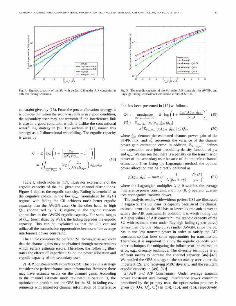
ALMADAR JOURNAL FOR COMMUNICATIONS, INFORMATION TECHNOLOGY, AND APPLICATIONS, VOL. 01, NO. 01, JULY 2014 17
−15 −10 −5 0 5 10 15 20
10−1
100
Qav
/N1B (dB)
Erg
odic
cap
acity
of t
he S
U (
nats
/s/H
z)
AWGNLognormal,σ=4dBLognormal,σ=8dBRayleighNakagami, m=2
Fig. 4. Ergodic capacity of the SU with perfect CSI under AIP constraint indifferent fading scenarios.
constraint given by (15). From the power allocation strategy, itis obvious that when the secondary link is in a good condition,the secondary user may not transmit if the interference linkis also in a good condition, which is dislike the conventionalwaterfilling strategy in [9]. The authors in [17] named thisstrategy as a 2-dimensional waterfilling. The ergodic capacityis given by
C = E
[log
(1 +
[gss
λN1Bgps− 1
]+)]
=
∫∫
gssλN1Bgps
≥1
log
(gss
λN1Bgps
)dgssdps
(18)
Table I, which holds in [17], illustrates expressions of theergodic capacity of the SU given the channel distributions.Figure 4 depicts the ergodic capacity. Fading is beneficial tothe cognitive radios. In the lowQav (normalized byN1B)regime, with fading the CR achieves mush better ergodiccapacity than the AWGN case. On the other hand, in highQav (normalized byN1B) regime, all the ergodic capacityapproaches to the AWGN ergodic capacity. For some rangesof Qav (normalized byN1B), the fading degrades the ergodiccapacity. This can be explained as that the CR can notutilize all the transmission opportunities because of the averageinterference power constraint.
The above considers the perfect CSI. However, as we knowthat the channel gains may be obtained through measurementswhich suffers estimate errors. Therefore, the following illus-trates the effects of imperfect CSI on the power allocation andergodic capacity of the secondary user.
2) AIP constraint with imperfect CSI:The previous strategyconsiders the perfect channel state information. However,theremay have estimate errors on the channel gains. Accordingto the channel estimate mode reviewed in Section II, theoptimization problem and the OPA for the SU in fading envi-ronments with imperfect channel information of interference
−10 −8 −6 −4 −2 0 2 4 6 8 10
10−1
100
Erg
odic
cap
acity
of t
he S
U (
nats
/sec
/Hz)
Qav
/(N0B) in dB
AWGNRayleigh
Rayleigh, σe2=0.01
Rayleigh, σe2=0.1
Rayleigh, σe2=0.4
Fig. 5. The ergodic capacity of the SU under AIP constraint for AWGN, andRayleigh fading with/without estimation errors of ST-PR.
link has been presented in [19] as follows.
O3 : maximizeps(gss,gps)≥0
E[log
(1 +
gssps(gss, gps)
N1B
)](19)
C13 : Egss,gps [ps(gss, gps)gps]
+ σ2eEgss,gps [ps(gss, gps)] ≤ Qav (20)
where gps denotes the estimated channel power gain of theST-PR link, andσ2
e represents the variance of the channelpower gain estimation error. In addition,Egss,gps [·] definesthe expectation over joint probability density function ofgssandgps. We can see that there is a penalty on the transmissionpower of the secondary user because of the imperfect channelestimation. Then Using the Lagrangian method, the optimalpower allocation can be directly obtained as
p∗s(gss, gps) = max
{0,
1
λ (gps + σ2e)
− N1B
gss
}(21)
where the Lagrangian multiplierλ ≥ 0 satisfies the averageinterference power constraint, andmax {0, ·} operator guaran-tees nonnegative transmit power.
The analytic results with/without perfect CSI are illustratedin Figure 5. The SU loses its capacity because of the channelestimate error that the SU has to lower its transmit power tosatisfy the AIP constraint. In addition, it is worth noting thatat higher values of AIP constraint, the ergodic capacity of theSU with estimate error under Rayleigh fading (green curve)is less than the one (blue curve) under AWGN, since the SUhas to use less transmit power in order to satisfy the AIPconstraint so that loses some opportunities for transmission.Therefore, it is important to study the ergodic capacity withother techniques for mitigating the influence of the estimationerror, e.g., diversity technique. The diversity techniqueis anefficient means to increase the channel capacity [46]–[48].We studied the OPA strategy of the secondary user under theimperfect CSI and receiving MRC diversity, and the resultantergodic capacity in [49], [50].
3) ATP and AIP Constraints:Under average transmitpower constraint and average interference power constraintpredefined by the primary user, the optimization problem isgiven by (O2, C1
2, C22) in (14), (15), and (16), respectively.

18 ALMADAR JOURNAL FOR COMMUNICATIONS, INFORMATION TECHNOLOGY, AND APPLICATIONS, VOL. 01, NO. 01, JULY 2014
TABLE IERGODICCAPACITY OF THE SU WITH PERFECTSCI UNDER AIP CONSTRAINT.
gss gps Ergodic Capacity (nats/s/Hz)
AWGN AWGN log(1 + Qav
N1B
)
Lognormal (σ2) Lognormal (σ2) log γ02
[1 + erf
(log γ02σ
)]+ σ√
πexp
(− log2 γ0
4σ2
)
Exponential (1) Exponential (1) log (1 + γ0)
Nakagami (m = 2) Nakagami (m = 2) log (1 + γ0) − γ0(1+γ0)2
* where γ0 = 1/λN1B.
−10 −5 0 5 10 150
0.5
1
1.5
2
2.5
3
3.5
4
4.5
Qav
(in dB)
Erg
odic
cap
acity
of t
he S
U (
bits
/s/H
z)
Pav
= −10dB
Pav
= −7.5dB
Pav
= −5dB
Pav
= −2.5dB
Pav
= 0dB
Pav
= 2.5dB
Pav
= 5dB
Pav
= 7.5dB
Pav
= 10dB
Pav
= 12dB
Pav
= 15dB
Fig. 6. The ergodic capacity of the SU under AIP and ATP constraints.
The associated optimal power allocation scheme for the sec-ondary user to maximize the ergodic capacity is given in [20]by
p∗s(gss, gps) =
(1
µ+ λgps− N1B
gss
)+
, (22)
where µ and λ are the nonnegative Lagrangian variablesassociated with the average transmit power constraint in (16)and average interference power constraint in (15), respectively.We can see that this scheme is also waterfilling. However,the water lever is related to not only the interference channelcondition, but also the average transmit power. Intuitively, evenhaving enough power budget for transmission and the CR linkhas a very good condition, the secondary user may not able totransmit if the interference channel in a very good condition.To solve this problem (O2, C1
2, C22) we used ellipsoid method
[51], [52], shown in Table II.We show the simulation results in the Figure 6 and in Figure
7, where we illustrate the ergodic capacity of the SU usingbits/s/Hz instead of nats/s/Hz only for a purpose of comparisonwith the original results shown in [20]. We can see from thefigures that at lowPav case the ergodic capacity is mainlyaffected by the average transmit power constraint, in otherwords, ATP dominates AIP. On the other hand, at highPav
regime, AIP dominates ATP.4) AIP constraint with imperfect CSI and receive MRC:
The optimal power allocation schemes and the associatedergodic capacity of the SU with receive MRC and imperfect
−10−5
05
1015
−10
0
10
200
1
2
3
4
5
Pav
(in dB)Qav
(in dB)
Erg
odic
cap
acity
of t
he S
U (
bits
/s/H
z)
Fig. 7. The ergodic capacity of the SU under AIP and ATP constraints.
ST-PR channel state information under the AIP constraint arepresented in detail in [50].
From previous analysis, we can see that under the long-term constraints the optimal power allocation approaches are(modified) waterfilling, and the water-level is jointly decidedby the long-term constraints. In the following, we will takea look at how the combined constraints, long-term and short-term, influence the power allocation and the ergodic capacity.
C. Combined Long-term and Short-term Constraints
This section reviews the optimal power allocation schemesand the ergodic capacity of the secondary user under thecombined long-term and short-term constraints, which is prettydifferent from the long-term constraints cases [53]. The opti-mization problem may be formulated as
O4 : maximizeps(gss,gps)≥0
E{log
(1 +
gssps(gss, gps)
N1B
)}(23)
C14 : ps(gss, gps)gps ≤ Qpk (24)
C24 : ps(gss, gps) ≤ Ppk (25)
C34 : E {ps(gss, gps)gps} ≤ Qav (26)
C44 : E {ps(gss, gps)} ≤ Pav (27)
where (24) represents the peak interference power (PIP)constraint, (25) is the peak transmit power (PTP) constraintindicating the maximal transmit power of the SU, (26) and(27) are the average interference power (AIP) constraint and

ALMADAR JOURNAL FOR COMMUNICATIONS, INFORMATION TECHNOLOGY, AND APPLICATIONS, VOL. 01, NO. 01, JULY 2014 19
TABLE IIELLIPSOID METHOD: PSEUDOCODE.
1) Initialization: (subscript or superscript,k, denotes thekth loop)λ1: Lagrangian multiplier associated to AIP.µ1 : Lagrangian multiplier associated to ATP.A1: a 2× 2 positive-definite matrix. An Ellipsoid,Ek, can be defined as
Ek(xk, Ak) =
{[λkµk
]:
([λkµk
]− xk
)T
A−1k
([λkµk
]− xk
)≤ 1
}, where
xk is the center ofEk .2) repeat{
a) calculatep(k)s using (22).
b) calculate the subgradients at
[λk
µk
]using
sg =
Qpk − E
{p(k)s (gss, gps)gps
}
Pav − E{p(k)s (gss, gps)
}
and normalized subgradientssg = sg/√
sgTAksgc) update the multipliers and the ellipsoid by[
λk+1
µk+1
]=
[λk
µk
]− Ak sg
2+1.
Ak+1 = 22
(2+1)2−1
(Ak − 2
2+1Ak sgsg
TAk
).
} until E{p(k)s (gss, gps)gps
}−Qpk ≤ 0, E
{p(k)s (gss, gps)
}− Pav ≤ 0,
and√
sgTAksg < ǫ, whereǫ is the desired accuracy.
the average transmit power (ATP) constraint, respectively.The optimization problem can be solved by using Lagrangianmethod. The numerical results can be obtained through usingbisection method.
1) PIP and AIP Constraints:Under the PIP and AIPconstraints predefined by the primary user, the optimizationproblem is given by(O4,C
14,C
34) in (23), (24), and (26).
The resultant optimal power allocation for the secondary userholds in [30] by
p∗(gss, gps) =
Qpk
gps,
gpsgss
< λ0
N1B1
λ1gps− N1B
gss, λ0
N1B≤ gps
gss≤ λ1
N1B
0, otherwise
(28)
where the Lagrangian multipliersλ0 ≥ 0 andλ1 ≥ 0 are asso-ciated to the PIP constraint given by (24) and AIP constraintby(26), respectively. We can see that the optimal power controlto achieve the secondary maximum ergodic capacity underjoint peak and average interference power constraints at theprimary receiver is a function of the channel state informationof the secondary user and of the link ST-PR. Compared tothe case that there is only AIP constraint, this strategy is acombination of channel inversion and water-filling. The ratioof the channel gains,gpsgss
, plays a key role in this case. InFigure 8, the ergodic capacity of the SU is plotted for AWGNand Rayleigh fading with different ratios ofρ =
Qpk
Qav. In
addition, for ρ > 1 the figure states that at higher valuesof Qav/(N1B), the PIP constraint can be ignored. Moreover,when ρ < 1 the secondary user loses some opportunitiesfor transmission resulting in lower ergodic capacity than theAWGN case at higher regime ofQav/(N1B).
2) PTP and AIP Constraints:The optimization problemunder peak transmit power constraint (PTP) and averageinterference power constraint is given by(O4,C
24,C
34) in
(23), (25), and (26). The optimal power allocation for thesecondary user to maximize the ergodic capacity holds in [20]
−10 −8 −6 −4 −2 0 2 4 6 8 10
10−1
100
Erg
odic
Cap
acity
of t
he S
U (
nats
/sec
/Hz)
Qav
/(N1B) in dB
AWGN, no PIPRayleigh, ρ=0.5Rayleigh, ρ=1Rayleigh, ρ=1.5Rayleigh, no PIP
Fig. 8. Ergodic capacity of the SU under average and peak interferenceconstraints for AWGN and Rayleigh fading with different values ofρ =
Qpk
Qav.
as
p∗s(gss, gps) =
Ppk, gps ≤ 1
λ(Ppk+N1Bgss
)1
λgps− N1B
gss, 1
λ(Ppk+N1Bgss
)< gps <
gssλN1B
0, gssλN1B
≤ gps(29)
The Lagrangian multiplierλ satisfies the following KTTcondition
Egss,gps [gpsp∗s(gss, gps)] = Qav (30)
The optimal power allocation scheme is a combination ofthe fixed power transmission and the water filling approach.Figure 9 depicts the simulation results. If there is no interfer-ence power constraint, the secondary user transmits by usingits maximal transmit power. With the combination of PTP andAIP constraints, if the value of the AIP constraint is smallercompared to the value of the PTP, the secondary user looses

20 ALMADAR JOURNAL FOR COMMUNICATIONS, INFORMATION TECHNOLOGY, AND APPLICATIONS, VOL. 01, NO. 01, JULY 2014
−10 −8 −6 −4 −2 0 2 4 6 8 100
0.5
1
1.5
2
2.5
3
Qav
(dB)
Erg
odic
Cap
acity
of t
he S
U (
nats
/sec
/Hz)
Ppk
=0dB
Ppk
=5dB
Ppk
=5dB, no interf. constr.
Ppk
=10dB, no interf. constr.
Ppk
=10dB
Ppk
=0dB, no interf. constr.
no transmit power constr.
Fig. 9. Ergodic capacity of the SU under different values of PTP and AIPconstraints over Rayleigh fading.
some opportunities to transmit. This corresponds to the AIP-dominant regime. On the other hand, if the PTP is dominant,the ergodic capacity is unbounded by the ergodic capacity withthe ATP constraint. This is because that the SU has a lot ofchances to transmit, but the PTP limits the ergodic capacity.
3) ATP and PIP Constraints:Under the average transmitpower constraint and peak interference power constraint, theoptimization problem is formulated by (O4,C
14,C
44) in (23),
(24), and (27). The resultant optimal power allocation for thesecondary user holds in [20] as
p∗s(gss, gps) =
Qpk
gps, gps ≥ Qpk
1λ−N1B
gss
, gss > λN1B
1λ − N1B
gss, gps <
Qpk
1λ−N1B
gss
, gss > λN1B
0, gss ≤ λN1B(31)
It is intuitive that the power allocation scheme is a combinationof channel inverse and waterfilling. The waterfilling reflectsthe average transmit power constraint and the channel inversereflects the peak interference power constraint. The simulationresults are shown in Figure 10. The ergodic capacity of the SUis capped bylog
(1 +
Qpk
gpsN1Bgss
). In the low-ATP regime, the
ergodic capacity is dominated by the ATP constraint, while inthe high-ATP regime the ergodic capacity is limited by the PIP.These can be explained as follows: In the low-ATP regime, thepower allocation scheme is mainly the water-filling, and in inthe high-ATP regime the power allocation scheme is performedas the channel inversion.
D. Summary
We can see that the strategies how the secondary userallocates the optimal transmit power to maximize the ergodiccapacity are decided by the types of constraints. When theconstraint is the peak interference constraint, the OPA is thechannel inversion with respect to the interference channelfrom the secondary transmitter to the primary receiver (ST-PR). If the constraint is the average interference constraint,the OPA is the water-filling scheme, where the water level isdecided by the interference channel, ST-PR, power gain. Forthe combined long-term and/or short-term constraints, theOPA
−10 −5 0 5 10 150
0.2
0.4
0.6
0.8
1
1.2
1.4
1.6
1.8
Pav
(dB)
Erg
odic
cap
acity
of t
he S
U (
nats
/s/H
z)
Without ATPWith ATP
Qpk
= 5 dB
Qpk
= 0 dB
Qpk
= −5 dB
Fig. 10. Ergodic capacity of the SU under different values ofATP and PIPConstraints over Rayleigh fading.
schemes are combined channel inversion and water filling ortwo-dimensional water filling. As we know that in the analysisof ergodic capacity, the delay limit is not considered whichmeans that it can be approaching to infinity. In the successivesection, we review the effective capacity which takes the delayinto consideration.
IV. EFFECTIVE CAPACITY
The concept of effective capacity (EC) has been reviewedin subsection II-B. This section reviews some results ofoptimal power allocation strategies and effective capacity ofthe secondary user over block fading channels. For simplicity,we in this section omit the parameters forps(θ, gss, gps), i.e.the transmit power of the SU is denoted asps. The objectivefunction and possible constraints are listed in the following,
O5 : maximizeps(θ,gss,gps)≥0
−1
θlog
[E(e−θTB log
(1+ psgss
N1B
))](32)
Constraints:
C15 : psgps ≤ Qpk (33)
C25 : ps ≤ Ppk (34)
C35 : E {psgps} ≤ Qav (35)
C45 : E {ps} ≤ Pav (36)
whereT denotes the block length duration,B is the channelbandwidth,θ is the delay exponent,Ppk denotes the maximumallowed peak transmit power,Pav denotes the average transmitpower constraint, andQpk and Qav represent the peak andaverage interference power threshold, respectively. We canuse Lagrangian method to solve the optimization problemswith different combinations of constraints. Without loss ofgenerality we assume thatTB = 1 andN1B = 1 in followingsimulations.
A. Short-term Constraint
The same as in the previous sections that the short-termconstraints include the peak transmit power constraint andthepeak interference power constraint.

ALMADAR JOURNAL FOR COMMUNICATIONS, INFORMATION TECHNOLOGY, AND APPLICATIONS, VOL. 01, NO. 01, JULY 2014 21
1) PTP and PIP Constraints:The optimization problem isgiven by (O5,C
15,C
35) in (32), (33), and (34). The power
allocation strategy is straightforward obtained that the SUtransmits using the power ofmin
(Ppk,
Qpk
gps
). Then the ef-
fective capacity can be obtained as
EC = −1
θlog
E
1 +
min(Ppk,
Qpk
gps
)gss
N1B
−θTB
(37)
Given the distributions of the fading channels, the expressionof the EC can be obtained numerically, since, to the bestof our knowledge, there are no closed-form expressions forthe common fading scenarios, e.g., Rayleigh and Nakagami-m. Thus we derive the upper bound expression, i.e. withoutconsidering the peak transmit power constraint, under inde-pendent Rayleigh fading for the effective capacity of this caseas a verification. Leth denote the ratio of two independentexponential variablesgssgps
, andh be the mean ratio ofgss/gps.Then we have the p.d.f. ofh by using [54, 5-15] as
f(h) =h
(h+ h
)2 (38)
ECub = −1
θlog
{E
[(1 +
QpkgssgpsN1B
)−θTB]}
= −1
θlog
E
[(1 +
Qpkh
N1B
)−θTB]
︸ ︷︷ ︸C1
where
C1 =
∫ ∞
0
(1 +
Qpkh
N1B
)−θTBh
(h+ h
)2 dh
= B(1, 1 + θTB) 2F1
(θTB, 1; θTB + 2, 1− Qh
N1B
)
where, in the last step, we have used [44, 3.197-1],2F1 (a, b; c, d) is hypergeometric function [44, 9.14], andB(a, b) denotes the beta function [44, 8.38].
Then we have
ECub = −1
θlog {B(1, 1 + θTB)
× 2F1
(θTB, 1; θTB + 2, 1− Qh
N1B
)} (39)
Figures 11 and 12 illustrate the effective capacity of theSU versus different values of the delay component along withthe different ratios of PIP and PTP over Rayleigh fading. Inthe simulation we assume that the mean value of the channelpower gains are 1, and the AWGN power at the receiver is1. First, it is intuitive that when the value ofQpk decreases,i.e. ρ decreases, the effective capacity of the SU decreases.Second, when the value ofρ is bigger than 1 , for instance,ρ = 1 andρ = 100, the effective capacity of the SU increasesslowly and will converge. This is because the peak transmit
power constraint becomes to dominate. In the two figures, wealso show the upper bounds given by Eq. (39), i.e. no peaktransmit power constraint, forQpk = −5dB andQpk = 5dB.
10−2
10−1
100
101
102
10−3
10−2
10−1
100
θ
Effe
ctiv
e ca
paci
ty o
f the
SU
(na
ts/s
/Hz)
ρ=0.001ρ=0.01ρ=0.1ρ=1ρ=100
ECup, Qpk
= 5dB
ECup, Qpk
= −5dB
Fig. 11. Effective capacity of the SU under different valuesof θ over Rayleighfading withPpk = −5dB, whereρ = Qpk/Ppk.
10−2
10−1
100
101
102
10−2
10−1
100
θ
Effe
ctiv
e ca
paci
ty o
f the
SU
(na
ts/s
/Hz)
ρ=0.001ρ=0.01ρ=0.1ρ=1ρ=10ρ=100
ECup, Qpk
= 5dB
ECup, Qpk
= −5dB
Fig. 12. Effective capacity of the SU under different valuesof θ over Rayleighfading withPpk = 5dB, whereρ = Qpk/Ppk.
B. Long-term Constraints
In the following, we review the optimal power allocationstrategies and the simulation results of the effective capacityof the SU under long-term constraints.
1) AIP Constraint:Under average interference power con-straint and secondary QoS constraint, the optimization problemis given by(O5,C
35) in (32) and (34). The resultant optimal
power allocation for the secondary user to maximize effectivecapacity holds in [38] by
p∗s =
N1B
[β
11+α
g1
1+αps g
α1+αss
− 1gss
]+, gps ≤ βgss
0, otherwise
(40)
where[x]+ = max(0, x), α = θTB, β = αλN1B
, andλ is thenon-negative Lagrangian variable associated with the averageinterference power constraint. Based on the above optimal

22 ALMADAR JOURNAL FOR COMMUNICATIONS, INFORMATION TECHNOLOGY, AND APPLICATIONS, VOL. 01, NO. 01, JULY 2014
−5 −4 −3 −2 −1 0 1 2 3 4 50
0.2
0.4
0.6
0.8
1
1.2
1.4
1.6
1.8
Qav
(in dB)
Effe
ctiv
e ca
paci
ty o
f the
SU
(na
ts/s
/Hz)
θ=0.001θ=0.01θ=0.1θ=1θ=10θ=20θ=50θ=100
Fig. 13. Effective capacity of the SU under different valuesof θ over Rayleighfading.
power allocation scheme, the closed-form expression of theeffective capacity of the SU over Nakagami-m fading channelswas derived in [38]. Here we show the simulations over i.i.d.Rayleigh fading channels.
From the simulation shown in Figure 13 we can see thatwhen the delay is stringent (θ has large values), the averageinterference power constraint sightly influences the effectivecapacity of the SU. This is because the SU needs to transmitat very low rate in order to fulfill the delay requirement. Thisis, the delay component dominates the effective capacity ofthe SU. On the other hand,θ is small, the AIP has dramaticinfluence on the effective capacity. The reason is that in lowerAIP regime the SU has very limited amount of opportunities totransmit; however, in higher AIP regime, the SU could utilizealmost all the opportunities for its transmission. Now the AIPdominates the effective capacity of the SU.
2) ATP and AIP Constraints:The results of the effectivecapacity under the average interference power and averagetransmit power constraints along with the QoS constraint,to the best of our knowledge, have not been proposed inliterature. In following we show our results.
The optimization problem is given by(O5,C35,C
45) in (32),
(35), and (36). The resultant optimal power allocation for thesecondary user to maximize effective capacity can be obtainedby using Lagrangian method as
p∗s = N1B
[α
11+α
(N1B (λgps + µ))1
1+α gα
1+αss
− 1
gss
]+(41)
whereα = θTB, andλ andµ are the non-negative Lagrangianvariables associated with the AIP constraint in (35) and ATPconstraint in (36), respectively. To the best of our knowledge,with the above optimal power allocation scheme there is noclosed-expression of the effective capacity. Here we show thesimulations in Figure 14 for i.i.d. Rayleigh fading channels.The optimal power can be obtained applying the pseudocodein Table II by using proper transmit power and interferenceconstraints. From the Figure, one thing we need to point outis that in the low ATP,Pav = −5dB, the ATP constraintdominates the effective capacity of the secondary user. This
10−2
10−1
100
101
0
0.2
0.4
0.6
0.8
1
1.2
1.4
θ
Effe
ctiv
e ca
paci
ty o
f the
SU
(na
ts/s
/Hz)
Qav
=−5dB, Pav
=−5dB
Qav
=5dB, Pav
=−5dB
Qav
=−5dB, Pav
=5dB
Qav
=5dB, Pav
=5dB
Fig. 14. Effective capacity of the SU over Rayleigh fading.
suggests us that when ATP≪AIP, the secondary user canignore the average interference constraint.
C. Combined Long- and Short-Term Constraints
To the best of our knowledge, the results of the effectivecapacity under the combined long-term and short-term con-straints have not been proposed in literature. In followingweshow our results.
1) ATP and PIP Constraints:Under average transmitpower and peak interference power constraints, and delayconstraint, the optimization problem is given by(O5,C
15,C
46)
in (32), (33) and (36). Using Lagrangian method, the resultantoptimal power allocation for the secondary user to maximizeeffective capacity is obtained as
p∗s =
min
{Qpk
gps, N1B
[β
11+α
gα
1+αss
− 1gss
]+}, 1 ≤ βgss
0, otherwise(42)
whereα = θTB, β = αλN1B
, andλ is the non-negative La-grangian variable associated with the average transmit powerconstraint. This power allocation is a water-filling schemebutcapped by the peak interference power constraint. Therefore,the water level is defined by these two constraints. To the bestof our knowledge, there is no closed-form expression for theeffective capacity for this case. Here we show the simulationsfor i.i.d. Rayleigh fading channels in Figure 15.
In Figure 15, we can discover two differences from theprevious case which is under AIP and ATP constraints. First,in low ATP, Pav = −5dB, cases, the values of the effectivecapacity for Qpk = −5dB and Qpk = 5dB are slightlydifferent. When the value of the delay componentθ is small,i.e. the delay is not stringent, the higherQpk value, thelarger effective capacity. However, whenθ is big, the EChas lower values whenQpk = 5dB than Qpk = −5dB.Second, in the case thatPav = 5dB, the gap of the effectivecapacity of the two cases,Qpk = 5dB andQpk = −5dB,increases. The effect of theQpk is similar in the lower andhigher value regimes ofθ. The phenomenon can be explainedas follows: whenθ is small, the secondary user is able to

ALMADAR JOURNAL FOR COMMUNICATIONS, INFORMATION TECHNOLOGY, AND APPLICATIONS, VOL. 01, NO. 01, JULY 2014 23
10−2
10−1
100
101
0
0.2
0.4
0.6
0.8
1
1.2
1.4
θ
Effe
ctiv
e ca
paci
ty o
f the
SU
(na
ts/s
/Hz)
Qpk
= −5dB, Pav
= −5dB
Qpk
= −5dB, Pav
= 5dB
Qpk
= 5dB, Pav
= −5dB
Qpk
= 5dB, Pav
= 5dB
Pav
= −5dB
Pav
= 5dB
Fig. 15. Effective capacity of the SU over Rayleigh fading under PIP andATP constraints.
utilize higher power to transmit when the opportunities appearwith the average transmit power budget; however, when delayrequirement is stringent, the secondary user needs to maintaina constant rate as possible not to use a higher power to obtaina higher instantaneous transmission rate. In later case, thesecondary user has more opportunities than the former casefor transmission.
2) PTP and AIP Constraints:Under peak transmit powerand average interference power constraints, and delay con-straint, the optimization problem is given by(O5,C
25,C
35) in
(32), (34) and (35). Using Lagrangian method, the resultantoptimal power allocation for the secondary user to maximizeeffective capacity is obtained as
p∗s =
min
Ppk, N1B
[β
11+α
g1
1+αps g
α1+αss
− 1gss
]+ ,
gpsgss
≤ β
0, otherwise(43)
where α = θTB, β = αλN1B
, and λ is the non-negativeLagrangian variable associated with the average interferencepower constraint. This power allocation scheme is capped bythe peak transmit power. Thus the water level of the waterfilling algorithm is different from the AIP-only case and theATP-PIP scenario that the water level is changing from blockto block. To the best of our knowledge, there is no closed-formexpression for the effective capacity for this case. In Figure 16we show the simulations for i.i.d. Rayleigh fading channels.
From Figure 16 we can see that when the average inter-ference power constraint is low,Qav = −5dB, higher peaktransmit power threshold is not an advantage at the higherPpk regime. In addition, the effective capacity of the case ofQav = 5dB andPav = −5dB is supreme over the case ofQav = −5dB andPav = 5dB at the stringent delay regime.This can be explained as that whenθ is large, the secondaryuser needs to maintain the rate as constant as possible, andin lower Qav and higherPpk case the SU has much lessopportunities to transmit than the case of higherQav andlower Ppk. Moreover, when the PTP constraint is lower andnot bigger thanQav, Ppk = −5dB, the AIP constraint can beignored.
10−2
10−1
100
101
0
0.2
0.4
0.6
0.8
1
1.2
1.4
θ
Effe
ctiv
e ca
paci
ty o
f the
SU
(na
ts/s
/Hz)
Qav
= −5dB, Ppk
= −5dB
Qav
= −5dB, Ppk
= 5dB
Qav
= 5dB, Ppk
= −5dB
Qav
= 5dB, Ppk
= 5dB
Ppk
= −5dB, Qav
= +/− 5dB
Fig. 16. Effective capacity of the SU over Rayleigh fading under AIP andPTP constraints.
V. CONCLUSION
In this paper, we reviewed the main results of the optimalpower allocation schemes for cognitive radios under differentconstraints and objectives.
The optimal power allocation schemes mainly can be cate-gorized as following:
• Channel inversion: when only the peak interferencepower constraint is applied, i.e. short-term constraint.
• Two-dimensional waterfilling: when the average transmitand/or interference power constraints are applied, i.e.long-term constraints.
• Capped two-dimensional waterfilling: when the aver-age/peak transmit power constraint and peak/average in-terference power constraint are considered, i.e. combinedlong- and short-constraints.
The ergodic capacity is mainly influenced by the interfer-ence channel from the secondary transmitter to the primaryreceiver. In addition, the effective capacity is affected by thedelay component besides the interference channel. Especially,the short-term constraints, i.e. peak transmit power and peakinterference power constraints, have different influencesonthe effective capacity over lower and higher delay componentregimes.
REFERENCES
[1] N. Hoven and A. Sahai, “Power scaling for cognitive radio,” in Proc.Int’l Conf. Wireless Netw., Commun. and Mobile Computing, Vol. 1,pp. 250–255, Jun. 2005.
[2] M. Chiang, P. Hande, T. Lan, and C. W. Tan, “Power control in wirelesscellular networks,”Foundations and TrendsR©in Networking, Vol. 2,No. 4, pp. 381–533, 2008.
[3] O. Kaya and S. Ulukus, “Optimum power control for cdma withdeterministic sequences in fading channels,”IEEE Trans. Inf. Theory,Vol. 50, No. 10, pp. 2449–2462, Oct. 2004.
[4] R. Knopp and P. Humblet, “Information capacity and powercontrolin single-cell multiuser communications,” inProc. IEEE ICC, Vol. 1,pp. 331–335, Jun. 1995.
[5] R. Yates, “A framework for uplink power control in cellular radiosystems,”IEEE J. Sel. Areas Commun., Vol. 13, No. 7, pp. 1341–1347,Sep. 1995.
[6] A. Goldsmith and P. Varaiya, “Capacity of fading channels with channelside information,”IEEE Trans. Inf. Theory, Vol. 43, No. 6, pp. 1986–1992, Nov. 1997.

24 ALMADAR JOURNAL FOR COMMUNICATIONS, INFORMATION TECHNOLOGY, AND APPLICATIONS, VOL. 01, NO. 01, JULY 2014
[7] A. Goldsmith, S. A. Jafar, I. Maric, and S. Srinivasa, “Breaking spectrumgridlock with cognitive radios: An information theoretic perspective,”Proc. IEEE, Vol. 97, No. 5, pp. 894–914, May 2009.
[8] S. Haykin, “Cognitive radio: brain-empowered wirelesscommunica-tions,” IEEE J. Sel. Areas Commun., Vol. 23, No. 2, pp. 201–220,Feb. 2005.
[9] T. M. Cover and J. A. Thomas,Elements of Information Theory, 2nd ed.John Wiley & Sons, Inc., 2006.
[10] Y. Chen, G. Yu, Z. Zhang, H. hwa Chen, and P. Qiu, “On cognitive radionetworks with opportunistic power control strategies in fading channels,”IEEE Trans. Wireless Commun., Vol. 7, No. 7, pp. 2752–2761, Jul. 2008.
[11] S. Srinivasa and S. A. Jafar, “Soft sensing and optimal power controlfor cognitive radio,” IEEE Trans. Wireless Commun., Vol. 9, No. 12,pp. 3638–3649, Dec. 2010.
[12] H. Islam, Y. chang Liang, and A. Hoang, “Joint power control and beam-forming for cognitive radio networks,”IEEE Trans. Wireless Commun.,Vol. 7, No. 7, pp. 2415–2419, Jul. 2008.
[13] L. Qian, X. Li, J. Attia, and Z. Gajic, “Power control forcognitiveradio ad hoc networks,” inProc. IEEE LANMAN Workshop, pp. 7–12,Jun. 2007.
[14] K. Koufos, K. Ruttik, and R. Jantti, “Controlling the interference frommultiple secondary systems at the tv cell border,” inPIMRC, pp. 645–649, 2011.
[15] M. Gastpar, “On capacity under received-signal constraints,” inProc.42nd Annual Allerton Conf. on Commun., Control and Comp.,(Monticello, IL, USA), Sept. 29 - Oct. 1 2004.
[16] ——, “On capacity under receive and spatial spectrum-sharing con-straints,” IEEE Trans. Inf. Theory, Vol. 53, No. 2, pp. 471–487,Feb. 2007.
[17] A. Ghasemi and E. S. Sousa, “Fundamental limits of spectrum-sharingin fading environments,”IEEE Trans. Wireless Commun., Vol. 6, No. 2,pp. 649–658, Feb. 2007.
[18] H. Suraweera, P. Smith, and M. Shafi, “Capacity limits and performanceanalysis of cognitive radio with imperfect channel knowledge,” IEEETrans. Veh. Technol., Vol. 59, No. 4, pp. 1811–1822, May 2010.
[19] L. Musavian and S. Aissa, “Fundamental capacity limitsof cognitiveradio in fading environments with imperfect channel information,” IEEETrans. Commun., Vol. 57, No. 11, pp. 3472–3480, Nov. 2009.
[20] X. Kang, Y.-C. Liang, A. Nallanathan, H. Garg, and R. Zhang, “Opti-mal power allocation for fading channels in cognitive radionetworks:Ergodic capacity and outage capacity,”IEEE Trans. Wireless Commun.,Vol. 8, No. 2, pp. 940–950, Feb. 2009.
[21] R. Zhang, “On peak versus average interference power constraints forprotecting primary users in cognitive radio networks,”IEEE Trans.Wireless Commun., Vol. 8, No. 4, pp. 2112–2120, Apr. 2009.
[22] L. Ozarow, S. Shamai, and A. Wyner, “Information theoretic consider-ations for cellular mobile radio,”IEEE Trans. Veh. Technol., Vol. 43,No. 2, pp. 359–378, May 1994.
[23] E. Biglieri, J. Proakis, and S. Shamai, “Fading channels: information-theoretic and communications aspects,”IEEE Trans. Inf. Theory, Vol. 44,No. 6, pp. 2619–2692, Oct. 1998.
[24] H. Ding, J. Ge, D. Benevides da Costa, and Z. Jiang, “Asymptoticanalysis of cooperative diversity systems with relay selection in aspectrum-sharing scenario,”IEEE Trans. Veh. Technol., Vol. 60, No. 2,pp. 457–472, Feb. 2011.
[25] J. Lee, H. Wang, J. G. Andrews, and D. Hong, “Outage probabilityof cognitive relay networks with interference constraints,” IEEE Trans.Wireless Commun., Vol. 10, No. 2, pp. 390–395, Feb. 2011.
[26] C. Zhong, T. Ratnarajah, and K.-K. Wong, “Outage analysis of decode-and-forward cognitive dual-hop systems with the interference constraintin nakagami- fading channels,”IEEE Transactions on Vehicular Tech-nology, Vol. 60, No. 6, pp. 2875 –2879, Jul. 2011.
[27] T. Duong, P. L. Yeoh, V. N. Q. Bao, M. Elkashlan, and N. Yang,“Cognitive relay networks with multiple primary transceivers underspectrum-sharing,”IEEE Signal Process. Lett., Vol. 19, No. 11, pp. 741–744, 2012.
[28] K. J. Kim, T. Duong, H. Poor, and L. Shu, “Performance analysis ofcyclic prefixed single-carrier spectrum sharing relay systems in primaryuser interference,”IEEE Trans. Signal Processing, Vol. 60, No. 12,pp. 6729–6734, Dec. 2012.
[29] R. Etkin, A. Parekh, and D. Tse, “Spectrum sharing for unlicensedbands,” IEEE J. Sel. Areas Commun., Vol. 25, No. 3, pp. 517–528,Apr. 2007.
[30] L. Musavian and S. Aissa, “Capacity and power allocation for spectrum-sharing communications in fading channels,”IEEE Trans. WirelessCommun., Vol. 8, No. 1, pp. 148–156, Jan. 2009.
[31] D. Tse and S. Hanly, “Multiaccess fading channels. I. polymatroidstructure, optimal resource allocation and throughput capacities,” IEEETrans. Inf. Theory, Vol. 44, No. 7, pp. 2796–2815, Nov. 1998.
[32] D. Wu and R. Negi, “Effective capacity: a wireless link model forsupport of quality of service,”IEEE Trans. Wireless Commun., Vol. 2,No. 4, pp. 630–643, Jul. 2003.
[33] ——, “Downlink scheduling in a cellular network for quality-of-serviceassurance,”IEEE Trans. Veh. Technol., Vol. 53, No. 5, pp. 1547–1557,Sep. 2004.
[34] C.-S. Chang and J. Thomas, “Effective bandwidth in high-speed digitalnetworks,”IEEE J. Sel. Areas Commun., Vol. 13, No. 6, pp. 1091–1100,Aug. 1995.
[35] J. Tang and X. Zhang, “Quality-of-service driven powerand rateadaptation over wireless links,”IEEE Trans. Wireless Commun., Vol. 6,No. 8, pp. 3058–3068, Aug. 2007.
[36] ——, “Quality-of-service driven power and rate adaptation for mul-tichannel communications over wireless links,”IEEE Trans. WirelessCommun., Vol. 6, No. 12, pp. 4349–4360, Dec. 2007.
[37] S. Akin and M. Gursoy, “Effective capacity analysis of cognitive radiochannels for quality of service provisioning,”IEEE Trans. WirelessCommun., Vol. 9, No. 11, pp. 3354–3364, Nov. 2010.
[38] L. Musavian and S. Aissa, “Effective capacity of delay-constrainedcognitive radio in Nakagami fading channels,”IEEE Trans. WirelessCommun., Vol. 9, No. 3, pp. 1054–1062, Mar. 2010.
[39] M. Gursoy, D. Qiao, and S. Velipasalar, “Analysis of energy efficiency infading channels under qos constraints,”IEEE Trans. Wireless Commun.,Vol. 8, No. 8, pp. 4252–4263, Aug. 2009.
[40] C.-X. Wang, X. Hong, H.-H. Chen, and J. Thompson, “On capacityof cognitive radio networks with average interference power con-straints,”IEEE Trans. Wireless Commun., Vol. 8, No. 4, pp. 1620–1625,Apr. 2009.
[41] J. Peha, “Sharing spectrum through spectrum policy reform and cogni-tive radio,” Proc. IEEE, Vol. 97, No. 4, pp. 708–719, Apr. 2009.
[42] S. Lim, H. Wang, H. Kim, and D. Hong, “Mean value-based powerallocation without instantaneous CSI feedback in spectrumsharingsystems,”IEEE Trans. Wireless Commun., Vol. 11, No. 3, pp. 874–879,Mar. 2012.
[43] Z. Rezki and M. Alouini, “Ergodic capacity of cognitiveradio underimperfect channel-state information,”IEEE Trans. Veh. Technol., Vol. 61,No. 5, pp. 2108–2119, Jun. 2012.
[44] I. Gradshteyn and I. Ryzhik,Table of Integrals, Series, and Products,Seventh Edition, 7th ed. Academic Press, 2007.
[45] R. Zhang, “Optimal power control over fading cognitiveradio channel byexploiting primary user CSI,” inProc. IEEE GLOBECOM, Nov. 2008.
[46] D. Brennan, “Linear diversity combining techniques,”Proc. IEEE,Vol. 91, No. 2, pp. 331–356, Feb. 2003.
[47] M.-S. Alouini and A. Goldsmith, “Capacity of rayleigh fading channelsunder different adaptive transmission and diversity-combining tech-niques,” IEEE Trans. Veh. Technol., Vol. 48, No. 4, pp. 1165–1181,Jul. 1999.
[48] I. E. Telatar, “Capacity of multi-antenna gaussian channels,”Eur. Trans.Telecomm., Vol. 10, No. 6, pp. 585–595, 1999.
[49] R. Duan, M. Elmusrati, R. Jantti, and R. Virrankoski, “Capacity forspectrum sharing cognitive radios with MRC diversity at thesecondaryreceiver under asymmetric fading,” inProc. IEEE Global Telecommu-nications Conference, pp. 1–5, Dec. 2010.
[50] R. Duan, R. Jantti, M. Elmusrati, and R. Virrankoski, “Capacity forspectrum sharing cognitive radios with MRC diversity and imperfectchannel information from primary user,” inProc. IEEE Global Telecom-munications Conference, pp. 1–5, Dec. 2010.
[51] R. G. Bland, D. Goldfarb, and M. J. Todd, “The ellipsoid method: Asurvey,”Operations Research, Vol. 29, No. 6, pp. 1039–1091, Dec. 1981,http://www.jstor.org/stable/170362.
[52] S. Boyd and L. Vandenberghe,Convex Optimization. New York, NY,USA: Cambridge University Press, 2004.
[53] M. Khojastepour and B. Aazhang, “The capacity of average and peakpower constrained fading channels with channel side information,” inProc. IEEE WCNC, Vol. 1, pp. 77–82, Mar. 2004.
[54] A. Papoulis and S. U. Pillai,Probability, Random Variables and Stochas-tic Processes, 4th ed. McGraw-Hill, 2002.

ALMADAR JOURNAL FOR COMMUNICATIONS, INFORMATION TECHNOLOGY, AND APPLICATIONS, VOL. 01, NO. 01, JULY 2014 25
On Effective Capacity of Cognitive Radios withTAS and MRC
Ruifeng Duan and Mohammed S. Elmusrati
Abstract—We investigate the effective capacity of a cognitive-shared channel with implementing transmit antenna selection atthe secondary transmitter and maximal ratio combining at thesecondary receiver under different transmit antenna selectionschemes, minimum interference selection, maximum secondarycomposite channel gain selection, and the maximum channel ratioselection. Closed-form expressions for the effective capacity arepresented and validated through simulations.
Index Terms—Cognitive radio, generalized selection combin-ing, ergodic capacity, symbol error probability.
I. I NTRODUCTION
FRom the literature we know that the ergodic capacityhas no transmission delay limitation, while the outage
capacity does not allow any delay. To this point, the conceptof effective capacity (EC) was developed in [1] to define themaximum arrival data rate that can be supported by the channelsubject to the required communication delay. It is a link-layerchannel model and can be interpreted as the dual of effectivebandwidth [2]. The quality of service (QoS) is represented by aterm, named QoS exponent. When the QoS exponentθ → 0,it means that there is no delay limitation, and the effectivecapacity equals the ergodic capacity. On the other hand, thelink cannot tolerate any delay asθ → ∞. This concept hasreceived much attention in the point-to-point case, e.g., [3],[4], as well as in cognitive radios, e.g., [5], [6] and referencestherein.
A combined transmitter antenna selection and receivermaximal ratio combing scheme was proposed in [7]. Theauthors investigated the system performance in terms of theaverage bit-error rate, and proved that the diversity orderofthe product of the number of transmit and receive antennascould be achieved, so that this scheme significantly improvesthe diversity. On one hand, this combined scheme providesnot only the diversity gain as the selection combining at thetransmitter and the selection combining at the receiver (SC/SC)but also provides the combining gain which the SC/SC doesnot have. On the other hand, using the SC at the transmitterreduces the complexity of the transmitter and transmit powerso that it is suitable in the uplink communication [7]. There-after, the transmit antenna selection (TAS) and the maximalratio combining (MRC) techniques have been extensively
The authors are with Communications and Systems Engineering Group,University of Vaasa, Finland. (emails: [email protected]; [email protected]).
The content of this paper is part of Duan’s thesis, and is reprinted with thepermission of the University of Vaasa. This work was supported in part bythe SMACIW (Statistical Modeling and Control of Aggregate Interference inWireless Systems, Decision no. 265077) project funded by the Academy ofFinland.
studied in the literature for traditional wireless communicationsystems, e.g. [8]–[10]. In [8], [9], the authors investigated theoutage probability and bit error rate of TAS/MRC in Rayleighand Nakagami-m fading channels, respectively. In [10], theauthors proposed the expressions of the outage probabilityofmultiuser diversity for a TAS/MRC system in independentand identically distributed Nakagami-m channels. The fulldiversity is achieved at high SNR regime.
Recently, the authors in [11] studied the ergodic capacityof a spectrum sharing secondary user link with TAS/MRC, inthe Rayleigh fading environment. The closed-form expressionof the ergodic capacity of the secondary user with peakinterference power constraint was derived, while the case withadditional peak transmit power for the SU was simulated.The ergodic capacity depends only on the product of thenumbers of transmit and receive antennas and the product ofthe peak signal-to-noise ratio (SNR) and the mean channelpower gain ratio. To the best of our knowledge, the EC of acognitive-shared channel with TAS/MRC in a Rayleigh fadingenvironment and the comparison of the EC with differenttransmit antenna selection schemes have not been studied inthe literature. We investigated this problem under differentselection schemes in this paper.
The remainder of this paper is organized as follows. InSection II, we present the system and channel model, and thetransmit selection schemes investigated in this paper, as wellas the probability density function (p.d.f) and cumulativedis-tribution function (c.d.f) of the SNR at the secondary receiver.In Section III, the EC of the SU under peak interference power(PIP) constraint is studied with different antenna selectiontechniques. In Section IV, the EC of the secondary userunder average interference power (AIP) constraint is analyzed.The results are then depicted in Section V. The last Sectionconcludes this paper.
II. SYSTEM AND CHANNEL MODEL
The spatial diversity scheme for a cognitive-shared channelinvestigated in this paper is depicted in Figure 1. This modelforms a combination of transmit antenna selection (TAS) atthe secondary transmitter (ST) and maximal ratio combining(MRC) at the secondary receiver (SR). The ST is equippedwith M antennas and the SR employsL receiving branchesthat are assumed to be independent from each other. Theprimary receiver (PR) has one antenna. We assume that thesecondary system is far away from the primary transmitter(PT), so that the interference from the PT to the SR isignored. This pattern has been adopted widely in the research

26 ALMADAR JOURNAL FOR COMMUNICATIONS, INFORMATION TECHNOLOGY, AND APPLICATIONS, VOL. 01, NO. 01, JULY 2014
Fig. 1. System Model: theith transmit antenna is selected.
of performance analysis of cognitive radio [6], [12]–[18].Inthis scenario, the secondary transmitter aims to maximize itseffective capacity, where the interference caused at the primaryreceiver must be regulated by the predefined interferenceconstraint. Therefore, the ST will select one of its transmitantennas by using proper transmit power to maximize itseffective capacity. in order to see how the different transmit an-tenna selection schemes influence the capacity, we study threescenario: minimum interference selection (Sel (1)), maximumsecondary composite channel gain selection (Sel (2)), and themaximum channel ratio selection (Sel (3)).
In addition, we consider underlay paradigm which is oneof the cognitive radio paradigms. In underlay paradigm, thesecondary and primary users could transmit simultaneously,if the interference caused by the secondary users to thelicensed users is below a predefined threshold [19]. Thisparadigm assumes that the secondary user has the channelstate information (CSI) of the interference channel from thesecondary transmitter to the primary receiver, which can begathered by the spectrum manager, primary receiver or a third-party device and then fed back to the secondary transmitter[13]. Of course, this CSI can be assumed to be perfect forsimplicity. However, in practice it is always imperfect dueto, such as, fading, Doppler, limited feedback channel, andmeasurement error. The interference can be regulated by theinterference temperature.
Let g(il)ss , which is assumed to be i.i.d∀l = 1, · · · , L, bethe channel power gain from theith antenna element of theST to thelth antenna element of the SR with meangss, g
(i)ss
denote the composite channel power gain from theith antennaelement of the ST to the SR, andg(i)ps represents the channelpower gain from theith antenna element of the ST to thePR. In our analysis, we assume that the wireless channelsexperience block Rayleigh fading assumed to be ergodic andstationary. Thus, the channel state does not change duringeach block, and the channel states are uncorrelated betweenblocks [20]. LetT denote the time duration of a block. Inconsequence, in a Rayleigh fading the channel power gaing(i)ps follows exponential distribution with mean valuegps.
The compound channel power gaing(i)ss is characterized bya Chi-square distribution with2L degrees of freedom, and the
corresponding p.d.f. and c.d.f. ofg(i)ss are given as follows [21]:
fg(i)ss(h)=
hL−1 exp (−h/gss)
gLss(L− 1)!, h ≥ 0, 1 ≤ i ≤ M (1)
Fg(i)ss(h)=
1
(L− 1)!γ
(L,
h
gss
)
= 1− exp
(− h
gss
) L−1∑
l=0
1
l!
(h
gss
)l
(2)
where the noise at each branch is assumed to be uncorrelatedadditive white Gaussian noise (AWGN). The p.d.f. ofg
(i)ps is
represented by
fg(i)ps(g) =
1
gpse−g/gps , g ≥ 0, 1 ≤ i ≤ M. (3)
The MRC technique requires perfect knowledge of thebranch amplitudes and phases, and provides the optimal di-versity. Hence, it offers the maximal capacity improvementrelative to other linear combining techniques [22]. The trans-mit power of the secondary transmitter is regulated by peakinterference power (Qpk) constraint or the average interferencepower (Qav) constraint at the primary receiver. We investigatethe following three schemes of transmit antenna selection ofthe secondary transmitter:
• Minimum interference selection (Sel (1)): the antennaelement at the secondary transmitter is selected whichcauses minimum interference to the primary user. Inother words, the interference channel (from the secondarytransmitter to the primary receiver, ST-PR) power gainis the minimum. In this case the ST uses only theinterference channel information for making selection.
• Maximum secondary composite channel gain selection(Sel (2)): the antenna element is selected to maximize thedata rate of the secondary user. That is, the antenna ele-ment which has maximum channel gain to the secondaryreceiver is selected (from the secondary transmitter to thesecondary receiver, ST-SR).
• Maximum channel ratio selection (Sel (3)): the antennaelement is selected at the secondary transmitter which hasthe maximal channel gain ratio ofg(i)ss /g
(i)ps .
For deriving the expressions of the effective capacity of thesecondary user, we first investigate the related p.d.f. and c.d.f.expressions in the following.
A. Minimum interference selection
The transmit antenna which minimizes the interference tothe primary is selected, i.e., the channel from the selectedantenna to the primary user has the minimal channel gainamong all antennas.
k = arg∀imin{g(i)ps
}, 1 ≤ i ≤ M. (4)
Using order theorem [23], the c.d.f. and the p.d.f. ofg(k)ps are
given by
Fg(k)ps
(g) = 1−[exp
(− g
gps
)]M(5)

ALMADAR JOURNAL FOR COMMUNICATIONS, INFORMATION TECHNOLOGY, AND APPLICATIONS, VOL. 01, NO. 01, JULY 2014 27
and
fg(k)ps
(g)= M
[exp
(− g
gps
)]M−1 exp(−g/gps
)
gps
=M
gps
[exp
(− g
gps
)]M(6)
Now we derive the probability distribution of the ratio,g(k)ss /g
(k)ps . Let z = g
(k)ss /g
(k)ps and w = g
(k)ps . The Jacobian
is given by
Jz,w = det
∣∣∣∣w z0 1
∣∣∣∣ = w (7)
The joint p.d.f. ofz andw.
fz,w = fg(k)ss ,g
(k)ps
(h = zw, g = w)w (8)
=M
gps
[exp
(− w
gps
)]M(zw)L−1e−zw/gss
gLss(L − 1)!w
The p.d.f. ofz.
fz(z) =
∫ ∞
0
fz,w(z, w) dw (9)
=MzL−1
gpsgLss(L − 1)!
∫ ∞
0
wL exp
(−Mw
gps− zw
gss
)dw
=MLρzL−1
(z +Mρ)L+1
whereρ = gss/gps. The last step is with the help of [24, eqn.3.351-1]
The c.d.f. ofz.
Fz(z)=
∫ z
0
fz(x) dx =
∫ z
0
MLρxL−1
(x+Mρ)L+1dx
=
(z
z +Mρ
)L
(10)
B. Maximum secondary composite channel gain selection
The transmit antenna which has maximal channel gain ofST-SR is selected, i.e., the channel from the selected antennato the secondary receiver has the maximal composite channelgain among all antennas.
k = arg∀imax{g(i)ss
}, 1 ≤ i ≤ M. (11)
Using order theorem [23], the c.d.f. of the maximum channelgain,g(k)ss , can be represented as
Fg(k)ss
(x)
=
M∏
l=1
Fhl(x) =
M∏
l=1
[1
(L− 1)!γ
(L,
x
gss
)](12)
=
M∏
l=1
[1− e−
xgss
L−1∑
kl=0
1
kl!
(x
gss
)kl]
=∑
n∈θM
M∏
l=1
(−1)nl
[e−
xgss
L−1∑
kl=0
1
kl!
(x
gss
)kl]nl
=∑
n∈θM
M∏
l=1
(−1)nle−x
gssnl
[L−1∑
kl=0
1
kl!
(x
gss
)kl]nl
=∑
n∈θM
e−x
gss
∑Ml=1 nl
M∏
l=1
(−1)nl
L−1∑
kl=0
Lnl−1
(kl!)nl
(x
gss
)klnl
=∑
n∈θM
L−1∑
k1=0
· · ·L−1∑
kM=0
e−x
gss
∑Ml=1 nlx
∑Ml=1 klnl
×M∏
l=1
(−1
kl!
)nl Lnl−1
gklnlss
=∑
n∈θM
L−1∑
k1=0
· · ·L−1∑
kM=0
Kn,ke−xBnxAn,k
whereθM is defined as the binary number set withM elements
Kn,k =
M∏
l=1
(−1
kl!
)nl Lnl−1
gklnlss
(13)
Bn =1
gss
M∑
l=1
nl (14)
An,k =
M∑
l=1
klnl (15)
The above proof follows the Lemma in [25] and [26]. Thep.d.f. can be obtained as following
fg(k)ss
(x) =d
dxFhmax(x)
=∑
n∈θM
L−1∑
k1=0
· · ·L−1∑
kM=0
Kn,ke−xBnxAn,k−1 [An,k − xBn]
(16)
Let z = g(k)ss /g
(k)ps andw = g
(k)ps . The Jacobian is given by
Jz,w = det
∣∣∣∣w z0 1
∣∣∣∣ = w (17)
The joint p.d.f. ofz andw can be obtained by
fz,w= fg(k)ss ,g
(k)ps
(h = zw, g = w)w
=1
gpse−w/gps
∑
n∈θM
L−1∑
k1=0
· · ·L−1∑
kM=0
Kn,ke−zwBn
×(zw)An,k−1 [An,k − zwBn]w (18)

28 ALMADAR JOURNAL FOR COMMUNICATIONS, INFORMATION TECHNOLOGY, AND APPLICATIONS, VOL. 01, NO. 01, JULY 2014
The p.d.f. ofz can be expressed as
fz(z)=
∫ ∞
0
fz,w(z, w) dw
=1
gps
∑
n∈θM
L−1∑
k1=0
· · ·L−1∑
kM=0
Kn,kzAn,k−1
×∫ ∞
0
e−w/gps−zwBnwAn,k [An,k − zwBn] dw
=∑
n∈θM
L−1∑
k1=0
· · ·L−1∑
kM=0
Kn,kgAn,k
×(An,kΓ(An,k + 1)zAn,k−1
(1 +Bngpsz
)An,k+1
−BngpsΓ(An,k + 2)zAn,k
(1 + Bngpsz
)An,k+2
)(19)
where in the last step we have used [24, eqn. 3.381-4].It is obvious that ifBn = 0, i.e. n ∈ 0M we also have
An,k = 0, thenfz(z) = 0. In the following, without loss ofgenerality we assume thatn ∈ θM representsn ∈ θM andn 6= 0M , where0M is binary set withM zero elements.
C. Maximum channel ratio selection
The transmit antenna which maximizeszi , g(i)ss
g(i)ps
is selected,
i.e.,
k = arg∀imax
{g(i)ss
g(i)ps
}, 1 ≤ i ≤ M. (20)
The p.d.f. ofzi can be obtained as follows.
fzi(x) =LρxL−1
(x+ ρ)L+1
(21)
whereρ = gss/gps.
Proof: Let zi =g(i)ss
g(i)ps
andw = g(i)ps . Then the Jacobian,
J(zi, w), is given by
Jzi,w(z, w) = det
∣∣∣∣w z0 1
∣∣∣∣ = w (22)
fzi,w(z, w)= fg(i)ss
(h = zw) fg(i)ps
(g = w)w
=(zw)L−1e−zw/gss
gLss(L− 1)!
1
gpse−w/gpsw
Then the marginal distribution ofzi can be obtained byintegratingfz,w(z, w) overw.
fzi(z)=
∫ ∞
0
fzi,w(z, w)dw
=
∫ ∞
0
(zw)L−1e−zw/h
hL(L− 1)!
1
ge−w/gwdw
=LρzL−1
(z + ρ)L+1
The c.d.f. can be obtained as
Fzi(z) =
∫ z
0
fzi(x)dx =
∫ z
0
LρxL−1
(x+ ρ)L+1
dv =
(z
z + ρ
)L
(23)Then according to the order theorem the p.d.f. ofzk can beobtained as
fzk(z) = M(Fzi(z))M−1fzi(z) = MLρ
zML−1
(z + ρ)ML+1
(24)
III. E FFECTIVE CAPACITY UNDER PIP CONSTRAINT
In this section we study the effective capacity of thesecondary user under peak interference power (PIP) constraintfor different transmit antenna selection schemes.
First, we again briefly review the concept of the effectivecapacity and derive a closed-form expression for the EC. Theprobability of the queue lengthq(x) of a stationary ergodicarrival and service process exceeding a certain thresholdTq
decays exponentially as a function ofTq [3]. The delay QoSexponent is defined as
θ = − limTq→∞
log(Pr {q(∞) > Tq})Tq
. (25)
It is worth noting thatθ → 0 indicates that the system hasno delay constraint, whileθ → ∞ implies a stringent delayconstraint. The effective capacity is defined in [1, Eqn. (12)]as follows,
EC(θ) = − limt→∞
1
θtlog[E(e−θ
∑ti=0 R[i]
)], t ≥ 0 (26)
where{R[i], i = 1, 2, ...} denotes a discrete-time service pro-cess, which is assumed to be ergodic and stationary. For ablock fading channel, the EC can be reduced to [3],
EC(θ) = −1
θlog[E(e−θR[i]
)]. (27)
The maximum achievable instantaneous service rateR[i] ofblock i can be expressed as
R[i] = TB log
(1 +
ps(θ, g(k)ss , g
(k)ss )g
(k)ss
N1B
)
where the superscriptk denotes thekth transmit antennabranch is selected,ps(θ, g
(k)ss , g
(k)ps ) is the transmit power of the
secondary transmitter,T denotes the block length duration,N1
denotes the AWGN power density at the secondary receiver,andB is the channel bandwidth. In the following we derivethe expressions of the effective capacity of the secondary userin different scenarios.
Notations: Let B(x, y) denote the Beta function givenby∫ 1
0tx−1(1 − t)y−1dt, and 2F1(a, b; c; z) be the Gauss’s
hypergeometric function [27]. For convenience, letα = θTB.
A. Minimum interference selection
In this case, the p.d.f. of the channel power gains,zk, isgiven by (9). The resultant effective capacity of the secondaryuser is given by the following theorem.
Theorem 1: The effective capacity of the cognitive-sharedchannel of Figure 1 under peak interference power constraint

ALMADAR JOURNAL FOR COMMUNICATIONS, INFORMATION TECHNOLOGY, AND APPLICATIONS, VOL. 01, NO. 01, JULY 2014 29
10−2
10−1
100
101
102
0
0.2
0.4
0.6
0.8
1
1.2
1.4
θ
Effe
ctiv
e ca
paci
ty o
f the
SU
(na
ts/s
/Hz)
M=1, L=1M=2, L=1M=4, L=1M=1, L=2M=1, L=4M=2, L=2
Fig. 2. Effective capacity of the SU versus QoS exponent under PIP constraintand minimum interference selection, where the mean channelpower gain ratioρ = 1, N1B = 1, andQpk = −5dB.
over Rayleigh fading with minimum interference selectionscheme is given by
EC(θ)= −1
θlog [LB(L, 1 + α)
× 2F1
(α,L;L+ 1 + α; 1 − QpkMρ
N1B
)](28)
Proof:
EC(θ)= −1
θlog
[Ezk
(e−α log
(1+
zQpkN1B
))]
= −1
θlog
[∫ ∞
0
(1 +
zQpk
N1B
)−αMLρzL−1
(z +Mρ)L+1dz
]
= −1
θlog [LB(L, 1 + α)
× 2F1
(a, L;L+ 1 + α; 1 − QpkMρ
N1B
)]
where in the last step, we have used Eqn. (3.197-1) in [24].
In Fig. 2 we show the effective capacity of the secondaryuser when the SU chooses the transmit antenna element havingthe minimum channel gain from the secondary transmitterto the primary receiver over different transmit and receivedegrees of diversity. Without loss of generality,N1B = 1.First, it is obvious that the TAS/MRC improves the achievableeffective capacity over a large range of the QoS exponent.Second, the performance of using multiple receive antennassurpasses the one using multiple transmit antennas, e.g. theperformance ofM = 1, L = 2 is better than the one ofM = 2, L = 1, andM = 1, L = 4 is better than the oneof M = 4, L = 1. Third, in this case usingM = 2 andL = 2 can not achieve the full diversity, because we onlyutilize partial channel information, i.e. only the interferencechannel information. Forth, at highθ regime,M = 1, L = 2is slightly better thanM = 4, L = 1. This is because theMRC is the optimal linear combing technique [22], and thebenefit of using TAS is not able to compensate the capacityloss caused by the channel deep fading.
B. Maximum secondary composite channel gain selection
In this case, the p.d.f. ofzk is given by (19). The resultanteffective capacity of the secondary user is given by thefollowing theorem.
Theorem 2: The effective capacity of the cognitive-sharedchannel of Figure 1 under peak interference power constraintover Rayleigh fading with maximum secondary compositechannel gain selection is given by
EC(θ) = −1
θlog
{ ∑
n∈θM
L−1∑
k1=0
· · ·L−1∑
kM=0
Kn,k
BAn,kn
[C1 + C2]}
(29)
whereC1 for Bn 6= 0 andC2 for Bn = 0 are given by
C1 =
[An,kΓ (An,k + 1)B(An,k, α+ 1)
× 2F1
(α,An,k;An,k + α+ 1; 1− Qpk
N1BgpsBn
)]
(30)
and
C2 =
[−Γ (An,k + 2)B(An,k + 1, α+ 1)
× 2F1
(α,An,k + 1;An,k + α+ 2; 1− Qpk
N1BgpsBn
)]
(31)
Proof: see Appendix A for details.
10−2
10−1
100
101
102
0
0.2
0.4
0.6
0.8
1
1.2
1.4
θ
Effe
ctiv
e ca
paci
ty o
f the
SU
(na
ts/s
/Hz)
M=1, L=1M=2, L=1M=4, L=1M=1, L=2M=1, L=4M=2, L=2
Fig. 3. Effective capacity of the SU versus QoS exponent under PIP constraintand maximum MRC channel gain, where the mean channel power gain ratioρ = 1, N1B = 1, andQpk = −5dB.
In Fig. 3 we show the effective capacity of the secondaryuser when the SU chooses the transmit antenna element havingthe maximum ST-SR channel gain over different transmitand receive degrees of diversity. First, it is obvious that theTAS/MRC improves the achievable effective capacity over alarge range of the QoS exponent. Second, in this case usingmore receiving antennas always (over the simulated range ofθ)is superior using more transmit antennas given the same valueof M ×L. This is different from the case of Sel (1) scheme atthe highθ regime. Third, the larger value ofM×L, the better

30 ALMADAR JOURNAL FOR COMMUNICATIONS, INFORMATION TECHNOLOGY, AND APPLICATIONS, VOL. 01, NO. 01, JULY 2014
10−2
10−1
100
101
102
0
0.2
0.4
0.6
0.8
1
1.2
1.4
θ
Effe
ctiv
e ca
paci
ty o
f the
SU
(na
ts/s
/Hz)
M=1, L=1M=2, L=1M=4, L=1M=1, L=2M=1, L=4M=2, L=2
Fig. 4. Effective capacity of the SU versus QoS exponent under PIP constraintand maximum channel radio selection, where the mean channelpower gainratio ρ = 1, N1B = 1, andQpk = −5dB.
performance the SU has. However, the performance of thescenario ofM = 1, L = 4 surpasses the one ofM = 2, L = 2.This is because the former case can use the full diversity whilethe later does not according to the antenna selection method.
C. Maximum Channel Ratio Selection
In this case the channel information of ST-PR and ST-SR areused to make the selection. Thus the secondary user utilizesthe full diversity of multiple antennas which can be seen fromthe following theorem and the simulation.
Theorem 3: The effective capacity of the cognitive-sharedchannel of Figure 1 with exploiting maximum channel ratioselection scheme under peak interference power constraintover Rayleigh fading is given by
EC(θ) =− 1
θlog
[MLB(ML,α+ 1)
× 2F1
(α,ML;α+ML+ 1; 1− Qpkρ
N1B
)]
(32)
Proof: see Appendix B for details.It is proved that the EC depends on the diversity orderM×
L, the QoS exponentθ, the product of the channel bandwidthand the channel coherence time (duration of fading block), theinterference power constraint, the noise power and the meanchannel power gain ratio. The simulated results are plottedinFig. 4.
We have investigated the performance of the secondary userin terms of the effective capacity under the peak interferencepower constraint. Next, we study the performance underaverage interference power constraint for the different antennaselection schemes.
IV. EFFECTIVE CAPACITY UNDER AIP CONSTRAINT
In this section we study the effective capacity of thesecondary user where the interference to the primary user
is limited by the average interference power,Qav. We mayformulate the following optimization problem.
maximize −1
θE
e
−α log
(1+
g(k)ss ps(θ,g
(k)ps ,g
(k)ss )
N1B
) (33)
subject to
E[g(k)ps ps(θ, g
(k)ps , g(k)ss )
]≤ Qav (34)
ps(θ, g(k)ps , g(k)ss ) ≥ 0 (35)
This optimization problem can be equivalently written as
minimize E
(1 +
g(k)ss ps(θ, g
(k)ps , g
(k)ss )
N1B
)−α (36)
subject to (34), (35)
The power allocation can be obtained through using La-grangian method as
ps(θ, g(k)ps , g(k)ss ) = N1B
β
11+α
g(k)ss
α1+α
g(k)ps
11+α
− 1
g(k)ss
+
(37)
where α = θTB, β = αλN1B
, and λ is the Lagrangianmultiplier associated to (34).
A. Minimum Interference Selection
In this case, the p.d.f. of the channel power gains,zk =
g(k)ss /g
(k)ps , is given by (9). Although this case is not practical
that the SU does not utilize all the channel state information(CSI) for making transmitter antenna selection, we here juststudy the impact of using CSI of ST-PR only on the effectivecapacity and the power adaptation uses all the CSI. Theresultant effective capacity of the secondary user is givenbythe following theorem.
Theorem 4: The effective capacity of the cognitive-sharedchannel of Figure 1 with exploiting minimum interferencechannel ratio selection scheme under average interferencepower constraint over Rayleigh fading is given by
EC(θ)
= −1
θlog
[1
(Mρβ)L2F1
(L+ 1, L;L+ 1;− 1
Mρβ
)
+MLρβ(1 + α)
1 + 2α
× 2F1
(L+ 1, 1 +
α
1 + α; 2 +
α
1 + α;−Mρβ
)
(38)
Proof: see Appendix C for details.The Lagrangian multiplier satisfies the following condition
Qav =MLρN1Bβ2
2
[2 + 2α
1 + 2α
× 2F1
(L+ 1, 1 +
α
1 + α; 2 +
α
1 + α;−Mρβ
)
− 2F1 (L+ 1, 2; 3;−Mρβ)
]
(39)

ALMADAR JOURNAL FOR COMMUNICATIONS, INFORMATION TECHNOLOGY, AND APPLICATIONS, VOL. 01, NO. 01, JULY 2014 31
Proof:
Qav =E[g(k)ps ps(θ, g
(k)ps , g(k)ss )
]
=
∫ ∞
0
N1B
[β
11+α
zα
1+α− 1
z
]+fzk(z) dz
=
∫ ∞
1/β
N1B
[β
11+α
zα
1+α− 1
z
]MLρzL−1
(z +Mρ)L+1dz
=N1BMLρ
[β
11+α
∫ ∞
1/β
zL− α1+α−1
(z +Mρ)L+1dz
−∫ ∞
1/β
zL−2
(z +Mρ)L+1dz
]
we then have the result by employing [24, Eqn. (3.194-2)] tothe last step.
10−2
10−1
100
101
102
0
0.2
0.4
0.6
0.8
1
1.2
1.4
θ
Effe
ctiv
e ca
paci
ty o
f the
SU
(na
ts/s
/Hz)
M=1, L=1M=2, L=1M=4, L=1M=1, L=2M=1, L=4M=2, L=2
Fig. 5. Effective capacity of the SU versus QoS exponent under AIP constraintand minimum interference selection, where the mean channelpower gain ratioρ = 1, N1B = 1, andQav = −5dB.
In Fig. 5 we show the effective capacity of the secondaryuser when the SU chooses the transmit antenna element havingthe minimum channel gain from the secondary transmitter tothe primary receiver over different transmit and receive degreesof diversity. First, it is obvious that the TAS/MRC improvesthe achievable effective capacity over a large range of the QoSexponent. Second, the performance of using multiple receiveantennas slightly surpasses the one using multiple transmitantennas at the range of small values ofθ, e.g. the performanceof M = 1, L = 2 is better than the one ofM = 2, L = 1,andM = 1, L = 4 is better than the one ofM = 4, L = 1.However, the gap rises whenθ increases. This phenomenon isdifferent from the one under PIP constraint. Third, in this caseusingM = 2 andL = 2 can not achieve the full diversity,because we only utilize partial channel information, i.e. onlythe interference channel information. Forth, at highθ regime,M = 1, L = 2 is slightly better thanM = 4, L = 1. Thiscan be explained as that the benefit of using TAS is not ableto compensate the capacity loss caused by the channel deepfading.
Comparing the results in Fig. 3 and Fig. 5, it is clear thatAIP constraint is more favorable than PIP constraint. Thisresult also confirms the conclusions drawn in [28] that the
AIP-based power allocations are more flexible to utilize theopportunities (channel fading states) for transmission, whereAIP-based power control depends on the both channels, ST-PRand ST-SR, while PIP-based one depends only ST-PR.
B. Maximum Secondary Composite Channel Gain Selection
In this case, the p.d.f. of the channel power gains,zk, isgiven by (19). The same as in previous subsection that theSU uses the CSI of ST-SR for making transmitter antennaselection, however, the power adaptation uses all the CSI. Theresultant effective capacity of the secondary user is givenbythe following theorem.
Theorem 5: The effective capacity of the cognitive-sharedchannel of Figure 1 with exploiting maximum secondarycomposite channel gain selection scheme under average in-terference power constraint over Rayleigh fading is given by
EC(θ) = −1
θlog
{ ∑
n∈θM
L−1∑
k1=0
· · ·L−1∑
kM=0
Kn,kgAn,kps [I1 + I2]
}
Proof: see Appendix D for details.The Lagrangian multiplier satisfies the following condition
Qav = N1B∑
n∈θM
L−1∑
k1=0
· · ·L−1∑
kM=0
Kn,kgAn,kps [Q1 −Q2] (40)
whereQ1 is given by (43) and (45), andQ2 is given by (44)and (46).
Proof: see Appendix E for details.
10−2
10−1
100
101
102
0
0.2
0.4
0.6
0.8
1
1.2
1.4
θ
Effe
ctiv
e ca
paci
ty o
f the
SU
(na
ts/s
/Hz)
M=1, L=1M=2, L=1M=4, L=1M=1, L=2M=1, L=4M=2, L=2
Fig. 6. Effective capacity of the SU versus QoS exponent under AIP constraintand maximum MRC channel selection, where the mean channel power gainratio ρ = 1, N1B = 1, andQav = −5dB.
We depict the results in Fig. 6. Besides the improve-ment through using multiple antennas, the performance ofthe scenario ofM1, L = 2 is not superior to the one ofM = 4, L = 1 as in the cases using Sel (1) scheme. Moreover,the performance of the cases with larger value ofM × Lsurpasses the ones with lower value ofM × L.
C. Maximum Channel Ratio Selection
This scheme uses the all the channel state information fortransmit antenna selection and for transmit power adaptation.

32 ALMADAR JOURNAL FOR COMMUNICATIONS, INFORMATION TECHNOLOGY, AND APPLICATIONS, VOL. 01, NO. 01, JULY 2014
Theorem 6: The effective capacity,EC(θ), of the cognitive-shared channel of Figure 1 with exploiting maximum channelratio selection scheme under peak interference power con-straint over Rayleigh fading is given by
− 1
θlog
[(1
ρβ
)ML
2F1
(ML+ 1,ML; 1 +ML;− 1
ρβ
)
+MLρβ
1 + α1+α
2F1
(ML+ 1, 1 +
α
1 + α; 2 +
α
1 + α;−ρβ
)]
(41)
Proof: see Appendix F for details.It is obviously that the EC depends on the diversity order
M × L, the QoS exponentθ, the product of the channelbandwidth and the channel coherence time (duration of fadingblock), the interference power constraint, the noise powerandthe mean channel power gain ratio. Fig. 7 depicts the results.The Lagrangian multiplier satisfies the following condition
Qav=MLρN1Bβ2
2
[2 + 2α
1 + 2α
×2F1
(ML+ 1, 1 +
α
1 + α; 2 +
α
1 + α;−ρβ
)
− 2F1 (ML+ 1, 2; 3;−ρβ)
](42)
Proof:
Qav= E[g(k)ps ps(θ, g
(k)ps , g(k)ss )
]
=
∫ ∞
0
N1B
[β
11+α
zα
1+α− 1
z
]+fzk(z) dz
=
∫ ∞
1/β
N1B
[β
11+α
zα
1+α− 1
z
]MLρzML−1
(z + ρ)ML+1
dz
= N1BMLρ
[β
11+α
∫ ∞
1/β
zML− α1+α−1
(z + ρ)ML+1dz
−∫ ∞
1/β
zML−2
(z + ρ)ML+1dz
]
we then have the result by employing [24, Eqn. (3.194-2)] tothe last step.
V. SIMULATION RESULTS
This section presents simulation results for the EC bycomparison. The same as in previous simulations, we assumeRayleigh block fading channels,TB = 1, and additive whiteGaussian noise powerN1B = 1.
Fig. 8 and Fig. 9 compare the EC of three selection schemesversusθ under peak interference power (PIP) constraint withdiversity orderM × L = 2 and M × L = 4, respectively.From Fig. 8 we can see that Sel (1) scheme is superior to Sel(2) at the low range of delay componentθ which representsdelay-insensitive regime. However, along with increasingthevalue of θ, Sel (2) becomes better than Sel (1). Moreover,The effective capacity is capped by using full diversity order.Fig. 9 shows the similar phenomenon as in Fig. 8. We may
10−2
10−1
100
101
102
0
0.2
0.4
0.6
0.8
1
1.2
1.4
θ
Effe
ctiv
e ca
paci
ty o
f the
SU
(na
ts/s
/Hz)
M=1, L=1M=2, L=1M=4, L=1M=1, L=2M=1, L=4M=2, L=2
Fig. 7. Effective capacity of the SU versus QoS exponent under AIP constraintand maximum channel radio selection, where the mean channelpower gainratio ρ = 1, andQav = −5dB.
10−2
10−1
100
101
102
0
0.1
0.2
0.3
0.4
0.5
0.6
0.7
0.8
0.9
θ
Effe
ctiv
e ca
paci
ty o
f the
SU
(na
ts/s
/Hz)
M=1, L=1Sel (1), M=2, L=1Sel (2), M=2, L=1Sel (3), M=2, L=1Sel (1), M=1, L=2Sel (2), M=1, L=2Sel (3), M=1, L=2
Fig. 8. Effective capacity comparison under PIP constraintand different TASschemes, where,M ×L = 2, the mean channel power gain ratioρ = 1, andQpk = −5dB.
10−2
10−1
100
101
102
0
0.2
0.4
0.6
0.8
1
1.2
1.4
θ
Effe
ctiv
e ca
paci
ty o
f the
SU
(na
ts/s
/Hz)
M=1, L=1Sel (1), M=4, L=1Sel (2), M=4, L=1Sel (3), M=4, L=1Sel (1), M=1, L=4Sel (2), M=1, L=4Sel (3), M=1, L=4Sel (1), M=2, L=2Sel (2), M=2, L=2Sel (3), M=2, L=2
Fig. 9. Effective capacity comparison under PIP constraintand different TASschemes, where,M ×L = 4, the mean channel power gain ratioρ = 1, andQpk = −5dB.
conclude that at the stringent case, i.e. lager values ofθ, withthe same diversity order the receiving diversity is superior to

ALMADAR JOURNAL FOR COMMUNICATIONS, INFORMATION TECHNOLOGY, AND APPLICATIONS, VOL. 01, NO. 01, JULY 2014 33
10−2
10−1
100
101
102
0
0.1
0.2
0.3
0.4
0.5
0.6
0.7
0.8
0.9
1
θ
Effe
ctiv
e ca
paci
ty o
f the
SU
(na
ts/s
/Hz)
M=1, L=1Sel (1), M=2, L=1Sel (2), M=2, L=1Sel (3), M=2, L=1Sel (1), M=1, L=2Sel (2), M=1, L=2Sel (3), M=1, L=2
Fig. 10. Effective capacity comparison under AIP constraint and differentTAS schemes, where,M×L = 2, the mean channel power gain ratioρ = 1,andQav = −5dB.
the transmit diversity.Fig. 10 and Fig. 11 show the results under average inter-
ference power constraint with diversity orderM × L = 2and M × L = 4, respectively. The significant differencein terms of effective capacity from the cases under peakinterference power constraint is the improvement by usingmultiple antennas at the highθ regime.
Taking look at these results, we can see that in high QoSexponentθ and under AIP constraint the gap in capacityachievement between different schemes remains slight differ-ence in opposite to the case of PIP constraint. This is becauseof the behavior of hypergeometric function,2F1(a, b; c;x).Also, when the QoS exponent goes to infinity, the EC is ap-proaching to the outage capacity. However, we leave the workof deriving the scaling laws as our future work. Additionally,in high QoS exponent and under PIP constraint, the EC ofMIMO, MISO, SIMO systems is reduced but still differentfrom the one of SISO system. This is another phenomenonthat AIP constraint is more favorable than PIP constraint.The secondary user could use some opportunities that the ST-PR channel experiences deep fading. Though, the multiplesantennas can benefit the secondary transmission, there is aPIP constraint such that the secondary user only can transmitwith certain amount power. Moreover, if at the same time, itsown channel is experiencing severe fading, the instantaneousrate will be low. In contrast, AIP-based power control schemeprovides the secondary user transmit opportunities by takinginto consideration both the ST-PR and ST-SR channel states.
In sum, the EC increases as the number of TAS/MRCantennas increases. And for given interference power con-straint at the primary receiver, the more stringent the QoSrequirement, e.g.,θ → ∞, the less the effective capacity is.This is because of the delay limitation. Different selectionschemes have different amount of advantages at various rangeof the delay exponentθ.
VI. CONCLUSION AND DISCUSSION
In this paper, we have studied and derived an expressionfor the effective capacity of a cognitive-shared channel with
10−2
10−1
100
101
102
0
0.2
0.4
0.6
0.8
1
1.2
1.4
θ
Effe
ctiv
e ca
paci
ty o
f the
SU
(na
ts/s
/Hz)
M=1, L=1Sel (1), M=4, L=1Sel (2), M=4, L=1Sel (3), M=4, L=1Sel (1), M=1, L=4Sel (2), M=1, L=4Sel (3), M=1, L=4Sel (1), M=2, L=2Sel (2), M=2, L=2Sel (3), M=2, L=2
Fig. 11. Effective capacity comparison under AIP constraint and differentTAS schemes, where,M×L = 4, the mean channel power gain ratioρ = 1,andQav = −5dB.
transmit antenna selection and maximal ratio combining underpeak or average interference power constraint. The resultsare compared for using different transmit antenna selectionstrategies, minimum interference selection, maximum sec-ondary channel gain selection, and maximum channel gainratio selection. The multiple antenna techniques improve thecommunication quality significantly.
However, we have more work to do in the future. In theprevious study, we considered only the perfect channel stateinformation cases. Thus the influence on the effective capacityof being provided imperfect channel state information, e.g.delayed channel information, channel information with mea-surement errors, or both, are also important for understandingcognitive radio systems. Moreover, we need to investigate themultiple users scenarios, for instance, multiple primary users,multiple secondary users, or both. Furthermore, some newselection schemes are needed to be developed and studied ifwe only have the channel statistics information without theinstantaneous channel state information, for instance, meanvalues. We will leave these as our future work.
APPENDIX
For simplicity, we use the following notation,
−→∑=∑
n∈θM
L−1∑
k1=0
· · ·L−1∑
kM=0

34 ALMADAR JOURNAL FOR COMMUNICATIONS, INFORMATION TECHNOLOGY, AND APPLICATIONS, VOL. 01, NO. 01, JULY 2014
A. Proof of Theorem 2
EC(θ)
= −1
θlog
[∫ ∞
0
(1 +
Qpk
N1Bz
)−α1
gps
−→∑ Kn,k
BAn,k+1n
×
An,kΓ(An,k + 1)zAn,k−1
(z + 1
Bngps
)An,k+1− Γ(An,k + 2)zAn,k
(z + 1
Bngps
)An,k+2
dz
= −1
θlog
[(Qpk/N1B)
−α
gps
−→∑ Kn,k
BAn,k+1n
∫ ∞
0
(N1B
Qpk+ z
)−α
×
An,kΓ(An,k + 1)zAn,k−1
(z + 1
Bngps
)An,k+1− Γ(An,k + 2)zAn,k
(z + 1
Bngps
)An,k+2
dz
then we have the result in (29) by implying [24, Eqn. (3.197-1)] to the above integration.
B. Proof of Theorem 3
−1
θlog
[Ezk
(e−α log
(1+
QpkN1B z
))]
= −1
θlog
[∫ ∞
0
(1 +
Qpk
N1Bz
)−α
MLρzML−1
(z + ρ)ML+1dz
]
= −1
θlog [MLB(ML,α+ 1)
× 2F1
(α,ML;α+ n+ 1; 1− Qpkρ
N1B
)]
where in the last step, we have used [24, Eqn. (3.197-1)].
C. Proof of Theorem 4
− 1
θlog[Ezk
(e−α log(1+psg
(k)ss /N1B)
)]
=− 1
θlog
[∫ ∞
0
(1 +
[β
11+α z
11+α − 1
]+)−α
× MLρzL−1
(z +Mρ)L+1dz
]
=− 1
θlog
[∫ 1/β
0
MLρzL−1
(z +Mρ)L+1dz
+
∫ ∞
1/β
β− α1+α z−
α1+α
MLρzL−1
(z +Mρ)L+1dz
]
We then have the result (38) by using [24, Eqn. (3.194-1) and(3.194-2)] to the integrals.
D. Proof of Theorem 5
EC(θ)
= −1
θlog
[∫ ∞
0
(1 +
[β
11+α z
11+α − 1
]+)−α −→∑Kn,kg
An,kps
× An,kΓ(An,k + 1)zAn,k−1
(1 +Bngpsz
)An,k+1−
BngpsΓ(An,k + 2)zAn,k
(1 +Bngpsz
)An,k+2
︸ ︷︷ ︸G
dz
= −1
θlog
−→∑Kn,kgps
An,k
∫ 1/β
0
G dz
︸ ︷︷ ︸I1
+
∫ ∞
1/β
β− α1+α z−
α1+α G dz
︸ ︷︷ ︸I2
where forAn,k 6= 0
I1 =Γ(An,k + 1)
βAn,k2F1
(An,k + 1, An,k;An,k + 2;−gpsBn
β
)
− BnΓ(An,k + 1)gps
βAn,k+1
× 2F1
(An,k + 2, An,k + 1;An,k + 2;−gpsBn
β
)
I2 =Γ(An,k + 1)β (1 + α)(gpsBn
)An,k+1(1 + 2α)
×[An,k 2F1
(An,k + 1, 1 +
α
1 + α; 2 +
α
1 + α;− β
gpsBn
)
− (An,k + 1) 2F1
(An,k + 2, 1 +
α
1 + α; 2 +
α
1 + α;− β
gpsBn
)]
and forAn,k = 0
I1 = −Bng
β2F1
(2, 1; 2;−gpsBn
β
)
I2 = − β (1 + α)
gpsBn (1 + 2α)
×2 F1
(2, 1 +
α
1 + α; 2 +
α
1 + α;− β
gpsBn
)
in the above we have used [24, Eqn. (3.194-1) and (3.194-2)]andΓ(1 + x) = xΓ(x).
E. Proof of the expression of Qav given by (40)
The proof is on the next page.
F. Proof of Theorem 6
The proof is on the next page.
REFERENCES
[1] D. Wu and R. Negi, “Effective capacity: a wireless link model forsupport of quality of service,”IEEE Trans. Wireless Commun., Vol. 2,No. 4, pp. 630–643, Jul. 2003.
[2] C.-S. Chang and J. Thomas, “Effective bandwidth in high-speed digitalnetworks,”IEEE J. Sel. Areas Commun., Vol. 13, No. 6, pp. 1091–1100,Aug. 1995.

ALMADAR JOURNAL FOR COMMUNICATIONS, INFORMATION TECHNOLOGY, AND APPLICATIONS, VOL. 01, NO. 01, JULY 2014 35
Proof of the expression ofQav given by (40).
Qav = E[g(k)ps ps(θ, g
(k)ps , g(k)ss )
]=
∫ ∞
0
N1B
[β
11+α
zα
1+α− 1
z
]+fzk (z) dz
=
∫ ∞
1/β
N1B
[β
11+α
zα
1+α− 1
z
] ∑
n∈θM
L−1∑
k1=0
· · ·L−1∑
kM=0
Kn,kgAn,kps
(An,kΓ(An,k + 1)zAn,k−1
(1 +Bngpsz
)An,k+1− BngpsΓ(An,k + 2)zAn,k
(1 +Bngpsz
)An,k+2
)dz
= N1B∑
n∈θM
L−1∑
k1=0
· · ·L−1∑
kM=0
Kn,kgAn,kps
β
11+αΓ(An,k + 1)
∫ ∞
1β
[An,kz
An,k− α1+α
−1
(1 +Bngpsz
)An,k+1− Bngps(An,k + 1)zAn,k+
11+α
−1
(1 +Bngpsz
)An,k+2
]dz
︸ ︷︷ ︸Q1
−[Γ(An,k + 1)
∫ ∞
1/β
An,kzAn,k−2
(1 +Bngpsz
)An,k+1− Bngps(An,k + 1)zAn,k−1
(1 +Bngpsz
)An,k+2dz
]
︸ ︷︷ ︸Q2
For An,k 6= 0, we by using [24, Eqn. (3.194-2)] have
Q1 =β2Γ(An,k + 1)(1 + α)(gpsBn
)An,k+1(1 + 2α)
[An,k 2F1
(An,k + 1, 1 +
α
1 + α; 2 +
α
1 + α;− β
gpsBn
)(43)
−(An,k + 1) 2F1
(An,k + 2, 1 +
α
1 + α; 2 +
α
1 + α;− β
gpsBn
)]
Q2 =β2Γ(An,k + 1)
2(gpsBn
)An,k+1
[An,k 2F1
(An,k + 1, 2; 3;− β
gpsBn
)(An,k + 1) 2F1
(An,k + 2, 2; 3;− β
gpsBn
)](44)
and forAn,k = 0
Q1 = −β2 (1 + α)
gpsBn 2
F1
(2, 1 +
α
1 + α; 2 +
α
1 + α;− β
gpsBn
)(45)
Q2 = − β2
2gpsBn2F1
(2, 2; 3;− β
gpsBn
)(46)
in the above we have used [24, Eqn. (3.194-2)] andΓ(1 + x) = xΓ(x).
Proof of theorem 6.
EC(θ)
= −1
θlog
[Ezk
(e−α log
(1+
psg(k)ss
N1B
))]= −1
θlog
[∫ ∞
0
(1 +
[β
11+α z
11+α − 1
]+)−α
×MLρzML−1
(z + ρ)ML+1
dz
]
= −1
θlog
[∫ 1/β
0
MLρzML−1
(z + ρ)ML+1dz +
∫ ∞
1/β
β− α1+α z−
α1+α
MLρzML−1
(z + ρ)ML+1dz
]
= −1
θlog
ML
(ρβ)ML(ML+ α
1+α
) × 2F1
(ML+ 1,ML+
α
1 + α;ML+ 1 +
α
1 + α;− 1
ρβ
)+MLρβ 2F1 (ML+ 1, 1; 2;−ρβ)
We have used [24, Eqn. (3.194-1) and (3.194-2)] to the above integrals.

36 ALMADAR JOURNAL FOR COMMUNICATIONS, INFORMATION TECHNOLOGY, AND APPLICATIONS, VOL. 01, NO. 01, JULY 2014
[3] J. Tang and X. Zhang, “Quality-of-service driven power and rateadaptation over wireless links,”IEEE Trans. Wireless Commun., Vol. 6,No. 8, pp. 3058–3068, Aug. 2007.
[4] ——, “Quality-of-service driven power and rate adaptation for mul-tichannel communications over wireless links,”IEEE Trans. WirelessCommun., Vol. 6, No. 12, pp. 4349–4360, Dec. 2007.
[5] S. Akin and M. Gursoy, “Effective capacity analysis of cognitive radiochannels for quality of service provisioning,”IEEE Trans. WirelessCommun., Vol. 9, No. 11, pp. 3354–3364, Nov. 2010.
[6] L. Musavian and S. Aissa, “Effective capacity of delay-constrainedcognitive radio in Nakagami fading channels,”IEEE Trans. WirelessCommun., Vol. 9, No. 3, pp. 1054–1062, Mar. 2010.
[7] S. Thoen, L. Van der Perre, B. Gyselinckx, and M. Engels, “Perfor-mance analysis of combined transmit-SC/receive-MRC,”IEEE Trans.Commun., Vol. 49, No. 1, pp. 5–8, Jan. 2001.
[8] Z. Chen, J. Yuan, and B. Vucetic, “Analysis of transmit antennaselection/maximal-ratio combining in Rayleigh fading channels,” IEEETrans. Veh. Technol., Vol. 54, No. 4, pp. 1312–1321, Jul. 2005.
[9] Z. Chen, Z. Chi, Y. Li, and B. Vucetic, “Error performanceof maximal-ratio combining with transmit antenna selection in flat Nakagami-mfading channels,”IEEE Trans. Wireless Commun., Vol. 8, No. 1, pp. 424–431, Jan. 2009.
[10] C.-C. Hung, C.-T. Chiang, N.-Y. Yen, and R.-C. Wu, “Outage probabilityof multiuser transmit antenna selection/maximal-ratio combining sys-tems over arbitrary nakagami-m fading channels,”IET Commun., Vol. 4,No. 1, pp. 63–68, Jan. 2010.
[11] V. Blagojevic and P. Ivanis, “Ergodic capacity for TAS/MRC spectrumsharing cognitive radio,”IEEE Commun. Lett., Vol. 16, No. 3, pp. 321–323, Mar. 2012.
[12] A. Ghasemi and E. S. Sousa, “Fundamental limits of spectrum-sharingin fading environments,”IEEE Trans. Wireless Commun., Vol. 6, No. 2,pp. 649–658, Feb. 2007.
[13] J. Peha, “Sharing spectrum through spectrum policy reform and cogni-tive radio,” Proc. IEEE, Vol. 97, No. 4, pp. 708–719, Apr. 2009.
[14] A. Jovicic and P. Viswanath, “Cognitive radio: An information-theoreticperspective,”IEEE Trans. Inf. Theory, Vol. 55, No. 9, pp. 3945–3958,Sep. 2009.
[15] X. Kang, Y.-C. Liang, A. Nallanathan, H. Garg, and R. Zhang, “Opti-mal power allocation for fading channels in cognitive radionetworks:Ergodic capacity and outage capacity,”IEEE Trans. Wireless Commun.,Vol. 8, No. 2, pp. 940–950, Feb. 2009.
[16] L. Musavian and S. Aissa, “Fundamental capacity limitsof cognitiveradio in fading environments with imperfect channel information,” IEEETrans. Commun., Vol. 57, No. 11, pp. 3472–3480, Nov. 2009.
[17] H. Suraweera, P. Smith, and M. Shafi, “Capacity limits and performanceanalysis of cognitive radio with imperfect channel knowledge,” IEEETrans. Veh. Technol., Vol. 59, No. 4, pp. 1811–1822, May 2010.
[18] R. Zhang, Y. chang Liang, and S. Cui, “Dynamic resource allocation incognitive radio networks,”IEEE Signal Process. Mag., Vol. 27, No. 3,pp. 102–114, May 2010.
[19] A. Goldsmith, S. A. Jafar, I. Maric, and S. Srinivasa, “Breaking spectrumgridlock with cognitive radios: An information theoretic perspective,”Proc. IEEE, Vol. 97, No. 5, pp. 894–914, May 2009.
[20] L. Ozarow, S. Shamai, and A. Wyner, “Information theoretic consider-ations for cellular mobile radio,”IEEE Trans. Veh. Technol., Vol. 43,No. 2, pp. 359–378, May 1994.
[21] J. Proakis and M. Salehi,Digital Communications, 5th ed. McGraw-Hill, 2008.
[22] D. Brennan, “Linear diversity combining techniques,”Proc. IEEE,Vol. 91, No. 2, pp. 331–356, Feb. 2003.
[23] H. A. David and H. N. Nagaraja,Order Statistics. Hoboken, NewJersey: John Wiley & Sons, Inc., 2003.
[24] I. Gradshteyn and I. Ryzhik,Table of Integrals, Series, and Products,Seventh Edition, 7th ed. Academic Press, 2007.
[25] F. Yilmaz, A. Yilmaz, M.-S. Alouini, and O. Kucur, “Transmit antennaselection based on shadowing side information,” inProc. IEEE VTC’11Spring, pp. 1–5, May 2011.
[26] A. Yilmaz, F. Yilmaz, M. Alouini, and O. Kucur, “On the performance oftransmit antenna selection based on shadowing side information,” IEEETrans. Veh. Technol., Vol. 62, No. 1, pp. 454–460, Jan. 2013.
[27] M. Abramowitz and I. A. Stegun, Eds.,Handbook of MathematicalFunctions, With Formulas, Graphs, and Mathematical Tables. DOVER,1964, 10th Printing with corrections, Dec. 1972.
[28] R. Zhang, “On peak versus average interference power constraints forprotecting primary users in cognitive radio networks,”IEEE Trans.Wireless Commun., Vol. 8, No. 4, pp. 2112–2120, Apr. 2009.

ALMADAR JOURNAL FOR COMMUNICATIONS, INFORMATION TECHNOLOGY, AND APPLICATIONS, VOL. 01, NO. 01, JULY 2014 37
Interference Mitigation Using Optimal SuccessiveGroup Decoding for Interference Channels
Omar Abu-Ella and Mohammed Elmusrati
Abstract—In this study we aim to assess the optimal successivegroup decoder (OSGD) considering different scenarios and in awide range of testing metrics. We investigate the OSGD in theK−user interference channel (IC) and evaluate its capabilityto mitigate interference. We inspect OSGD performance interms of its (ergodic and effective) capacity. Also, we evaluateits minimum required energy per bit, bit error rate (BER),and outage probability, under different quality of service (QoS)constraints. This study considers both the spatially correlatedand uncorrelated (Rayleigh and Rician) flat fading channels.In addition, it explores performance of the OSGD in differentSNR and SIR environments, where we consider both the power-limited and bandwidth-limited regimes with various cross-talkvalues, taking in account several transmit-receive multiple-inputmultiple-output (MIMO) antenna configurations. The obtainednumerical results in this work, show that OSGD technique ex-hibits very efficient performance to cope with interferencein theinvestigated scenarios, proving by that its competency comparingto the most developed interference cancellation approaches.1 Thismakes OSGD a favorable technique for interference reduction;especially, if we bear in mind that OSGD is formed on receive-side processing only. This confirmed also if we contemplatethe reduction of its arithmetic complexity, as a result of itsinnate complexity controlling characteristic, comparing to thelarge computational complexity of the other optimal interferencecancellation schemes, such as, the maximum likelihood multi-user detection (ML-MUD) or the other iterative interferencealignment schemes.
Index Terms—Interference Mitigation, Optimal Successive,Group Decoding, Interference Channels, MIMO, InterferenceAlignment, Effective Capacity.
I. I NTRODUCTION
T He accelerated expansion of wireless communication isforeseen to carry on due to the quick move towards the
next generation technologies. This inspires researchers to makepromising development to realize peak bit rates as high as 1Gbit/s and more. Achievement of such rate is predicted to befacilitated by the deployment of distributed broadband wire-less communications (BWC) systems. This indicates that theessential importance in the prospect wireless communicationsystems is to devise wireless transceivers with the capabilityto communicate in a reliable manner in the existence ofinterferers [1]. Therefore; studying the interference channel(IC) and its adopted technologies becomes an indispensableto keep up and to cope with the demands of such emergingwireless networks.
Therefore, as a starting point we define the interferencechannel as in [2] by the channel of multi pairs of input-
1Part of the results in this article has been published by OmarAbu-Ella, andMohammed Elmusrati, onOptimal Successive Group Decoding to MitigateInterference in Wireless Systems.In Proc. 10th IEEE International Conferenceon Distributed Computing in Sensor Systems (DCOSS ’14).
output terminals, where each input communicates through acommon medium with its respective outputs. Also, authors of[3] presented the interference channel as a model for studyingnetworks with two or more (source-destination) pairs wherethe signals of the sources interfere with each other at thedestination.
Now, we proceed to introduce one of the most crucialprinciples of the interference channel systems, which is how tointerpret the interference effect, traditional wireless transceiverdesigners commonly view interference as an augmentation tothe additive Gaussian noise. This assumption is not consis-tently true; it is valid only if the employed detectors do nottake into consideration the interference formation; however, infact, practical systems have some level of knowledge aboutinterference; because the signals emitted by the interferersbelong to discrete constellations [4]. In the light of thisfact and because of interference management is essential toattain higher spectral efficiency and thereupon higher peakbit rates, researchers have evolved and enhanced abundant ofinterference-aware mitigation techniques. One of those meth-ods has lately grabbed much research concentration, knownas (interference alignment) [5]–[7]. Interference alignmentis fundamentally established on the concept of designingtransmitter and receiver to align interfering signals to eachother at receiver side [8]. More precisely, vector interferencealignment divides the dimensions of the receiver observationspace to two subspaces, one of the subspaces is occupiedby the desired signal and all the undesired interference arealigned to the other subspace. From the theoretical point ofview, interference alignment is claimed to establish optimalityto approach Shannon capacity of interference network athigh SNR [9]. However, the existing interference alignmentschemes in fact are facing very challenging problems when itcomes to practical implementation. Here we state some of thechallenges that considered as strain in practical implementa-tion of interference alignment algorithms:
• Generally, analytical solution for the interference align-ment is difficult to obtain. The existing closed formsolutions are only been founded for certain cases withvery limited number of users.
• When the closed form expression exists, global channelknowledge is required to obtain such a closed formsolution, which is of course requires an overwhelmingfeedback overhead. In practice, restricted feedback con-ditions, can lead to imperfect channel state information atthe transmitter (CSIT), which severely affects the systemefficiency and performance.
• The required signaling dimension of interference align-

38 ALMADAR JOURNAL FOR COMMUNICATIONS, INFORMATION TECHNOLOGY, AND APPLICATIONS, VOL. 01, NO. 01, JULY 2014
ment scheme grows exponentially with the total numberof users in the system; consequently, a question rises upabout the impracticality of implementing such a system.
• Although, the distributed interference alignment algo-rithms require only local channel knowledge at each node,it is yet require an extensive computational complex-ity due to the iterative manner of finding its optimumsolution. In addition, the final values and the conver-gence speed of the kernel iterative algorithm, which thedistributed interference alignment schemes rely on tooptimize their objective function, is very sensitive to theinitialization conditions.
• To avoid feedback some of interference alignmentschemes are build on the assumption of reciprocity ofthe wireless network which does not always hold.
To overcome all the previously stated challenges facing in-terference alignment strategy, we have to look for (no orvery limited) feedback system with tolerable complexity usingnon-iterative technique. We try to avoid feedback becausethe exhibited overall achieved capacity of the feedback-basedregimes, for instance, in the case of interference alignmentschemes, can be misleading when it is compared to non-feedback system capacity. In other words, feedback in somecases can hurt the system more than helping it, by decreasingthe pure throughput of the system. Consequently, our goal isto have a better strategy to mitigate interference with limitedfeedback. So, we should avoid all interference mitigation pro-cesses at the transmitter side, and consider only the approacheswith the operations at the receiver side, at the same time, wewant to accomplish this task within a feasible computationalcomplexity.
Looking for another track of research to cope with inter-ference, we encounter an alternative traditional methodology,which is based on designing decoders in presence of inter-ference. This approach employs one of the two followingtechniques: successive interference cancelation for small SIRregimes [10], or, on the other hand, treating interference likenoise for larger SIR regimes. This can be seen in power allo-cation systems for frequency selective Gaussian interferencechannels [11], and in CDMA cellular communication systemdesign [12]. However, there is still some range of SIR whenboth of these techniques are suffering from an error floor [13].
Motivated by the necessary need for an optimal interferencemitigation technique considers all ranges of interferencelevels,a novel interference mitigation scheme proposed in [14], wherethe authors assumed that each receiver uses a successivegroup decoder (SGD) which is considered as an extensionof the conventional successive decoder, however, instead ofdecoding only one user at each decoding stage, a subgroupof users are jointly decoded. Considering an interferencechannel system where a fixed power allocated to all users andassuming predetermined rates for all transmitters, the authorsof [14] obtained the decoding strategy minimizes the outageprobability at every receiver and generates the optimal subsetof interferers that must be decoded along with the desired userunder an imposed complexity constraint.
It is worth to mention that successive group decoders havea substantial feature, that they can be implemented with
different levels of complexity. They can be implemented withas low complexity as the conventional successive single-userdecoder to the high-complexity of the maximum likelihooddecoder. Therefore, by imposing a constraint on the decodercomplexity, we can adopt the decoder with an adequatecomplexity that each receiver can sustain. In this stream ofresearch, a constrained partial group decoding (CPGD) schemewas proposed in [15], [16]. In this technique, each receiveremploys a constrained partial group decoder to decode itsdesired message conjointly with a part of the interference.In other words, this decoder exploits the knowledge aboutthe interference to determine which interfering signals (witha constraint on their group size) should jointly decoded alongwith the desired signal, while treating the remaining interferingsignals as Gaussian noise.
The bottom line contribution of this work is to explorethe efficiency of using the OSGD in the interference channelsystems, by extensively inspecting its performance in terms ofachieved (ergodic and effective) capacity. In addition to that,we evaluate its minimum required energy per bit, BER, andoutage probability, under different quality of service (QoS)constraints. For generality purposes, this study considers boththe spatially correlated and uncorrelated (Rayleigh and Rician)flat fading channels. Moreover, it investigates the operation ofthe OSGD in different SNR and SIR environments, wherewe consider both the power-limited and bandwidth-limitedregimes with different cross-talk values, as well as consid-ering different transmit-receive multiple-input multiple-output(MIMO) antenna configurations. To make our results moresensible, we contrast the aforementioned performance withthose of other well known interference mitigation approaches,such as, maximum likelihood multi-user detection (ML-MUD)and interference alignment technique.
The remainder of this work is organized as follows: Sec-tion II defines the used notation in this work. Followed bySection III describing the model of interference channel whichapplied in this study. A brief description of the addressedconcepts and interference mitigation techniques is presentedin Section IV. Complexity issues related to the presentedschemes are discussed in Section V. Numerical results of thedifferent scenarios in terms of achieved ergodic and effectivecapacity, minimum required energy per bit, in addition to thebit error rate and outage probability performance evaluationare demonstrated in Section VI. Finally, Section VII concludesthis study.
II. N OTATION
Scalars represented in this study with lowercase italics, vec-tors, and matrices denoted respectively by lowercase boldfaceand uppercase boldface; superscripts·T and ·H symbolizethe transpose and Hermitian (complex-conjugate) transpose;[·]i,j stands for the(i, j)th element of a matrix;tr(A) impliesthe trace of matrixA; abs(·) designates the absolute value;‖H‖2 =
∑Nr
i=1
∑Nt
j=1 |[H]i,j |2 = tr(HHH) is the squaredFrobenius norm ofH; E{·} expresses the statistical average;∼denotes the distribution equivalence between the left and rightrandom variables;≈ means approximately equals;, means

ALMADAR JOURNAL FOR COMMUNICATIONS, INFORMATION TECHNOLOGY, AND APPLICATIONS, VOL. 01, NO. 01, JULY 2014 39
is equal by definition to; the operator(x)+ , max(0, x) isthe projection on the nonnegative orthant;⊗ indicates thekronecker product; uppercase calligraphic letter (e.g.,M)indicates a finite set of integers; the underlined uppercasecalligraphic letter (e.g.,G) represents the ordered partition ofa set;|A| indicates cardinality of the setA; ∈ stands for: iselement of;B ⊆ D indicates thatB is a subset ofD; Pr(·) is ashorthand for the probability of;log(·) expresses the logarithmterm.
III. I NTERFERENCECHANNEL MODEL
We consider only the temporally uncorrelated discretemodel of a flat-fadingK-user interference channel (IC) de-picted in Fig. 1. In this study we assume that each transmitteris equipped withNt ≥ 1 antennas, and intends to commu-nicate with its designated receiver which is equipped withNr ≥ 1 antennas. But, due to the broadcasting nature ofthe wireless channel the transmitted signal is received by allthe K receivers. Thekth receiver is interested only in thesignal transmitted by thekth transmitter; however, it is awareof the coding scheme employed by all other users, (this ispractical assumption since the security of the informationcanbe maintained by using proper encryption techniques). Thereceiver may choose to decode some or all of the users onlyif it presumes that will assist the decoding of its intendeduser. The received signal of thekth receiver at thenthsymbol interval through a K-user interference channel can beexpressed by
yk[n] =√PHkkxk[n] +
√αP
K∑
i=1,i6=k
Hkixi[n] + zk[n],
1 ≤ k ≤ K (1)
where yk[n] is the Nrk × 1 received signal vector. further,in this system we assume a quasi static flat fading scenario,where the channel gain experienced by thekth receiver fromthe ith transmitter is described by theNrk ×Nti matrix Hki
consists as in [17], [18] of two components, deterministic (i.e.,mean) denoted byHd and random component represented byHr
H =
√K
1 +KHd +
√1
1 +KHr (2)
where√
K1+K is the LOS component of the channel and√
11+K is the fading component, assuming uncorrelated flat
fading.K is the RiceanK-factor of the channel and is definedas the ratio of the power in the LOS component of the channelto the power in the fading component.
K =‖Hd‖2
E{‖Hr‖2}(3)
It is clear that forK = 0, the MIMO channelHki has a pureRayleigh fading, also, if0 < K <∞, then,Hki has a Ricianfading; while, the case ofK =∞ corresponds to a non-fadingchannel scenario.
In this study, we use the Kronecker correlation modelexpressed in (4) to simulate the correlation effect in the
x2
x1
y1
y2
H 12
H 11
H 22
H 21
xK
yK
H 1K
H 2K
H K1H K2
H KK
Fig. 1: The interference channel.
both ends of the channel, i.e., in the transmit and receivesides. Despite its simplicity, Kronecker model seems to bea reasonable choice when the correlation is quickly vanishingwith the distance between the transmit and receive ends [19].
Hr = R12r HwR
12t (4)
where Hw is an (Nr × Nt) normalized complex Gaussianrandom matrix,Rt, Rr, are the deterministic correlation ma-trices at the transmit and receive end respectively. Because ofits simplicity and relative accuracy to simulate the realisticantenna inter-element correlation, we adopted the exponentialcorrelation model to generate the transmit and receive corre-lation matrices, where they can be constructed using a singlecorrelation factorρ ∈ C and |ρ| ≤ 1 as follows
Rij =
{ρabs(j−i) , i 6 j(ρabs(j−i)
)∗, i > j
(5)
In this work, Hki is assumed to be perfectly known to thekth receiver, but it is unknown to any of the transmitters andany other receiver.zk[n] is the Ntk × 1 complex additivewhite Gaussian noise (AWGN) vector at the receiverk. Itis assumed to have independent and identically distributed(i.i.d.)∼ CN (0, 1) elements and it is temporally uncorrelated.P represents the average transmit power used by theith user.α denotes the cross-talk factor between users, i.e., it representsthe relative propagation path loss of the interference channel.xi[n] represents a unit power symbol vector transmitted fromthe ith user during thenth time interval. Hereafter, for thesake of simplicity, we omit the symbol interval indexn.
IV. OVERVIEW FOR THEADDRESSEDCONCEPTS AND
SCHEMES
This section gives a brief review for the concepts and thedifferent systems which we address in this study. This sectionis concluded by detailed description of the main idea of theOSGD and its employed algorithms.

40 ALMADAR JOURNAL FOR COMMUNICATIONS, INFORMATION TECHNOLOGY, AND APPLICATIONS, VOL. 01, NO. 01, JULY 2014
A. Effective Capacity
Modeling the wireless channel regarding to the connectionquality of service (QoS) metrics such as delay, ratio of packetloss and bandwidth is crucial to promote the QoS in thefuture wireless networks. However, the commonly adoptedconventional physical-layer wireless models do not preciselydistinguish these QoS metrics. Intelligently, authors in [20],proposed and develop a new approach to model the channelQoS, they introduced a new terminology called (effectivecapacity, EC) analogous to the (effective bandwidth), wherethey assessed the wireless channel by two EC parameters,the probability of non-empty buffer, and the connection QoSexponent.
The first metric, i.e., the non-empty buffer probability isequivalent in concept to the outage probability of the system,where the later means that the signal-to-noise ratio (SNR)at the receive falls below a specific threshold. However, theprobability of non-empty buffer does not equal the outageprobability; because, the former considers the packet accumu-lation effect on the system, while, the later dose not. Therefore,the outage probability is less than the probability of non-emptybuffer [20].
Generally, effective capacity is defined as in [21], [22] bythe maximum fixed rate of arrival, that can be supported bysome service process, such that, the requirements specifiedbythe QoS exponent are statistically guaranteed. More explicitly,if we defineQ as the stationary length of a queue, then, thedecaying rate of the tail ofQ distribution, which denoted byθ is given by
θ = − limq→∞
1
qlogPr(Q ≥ q) (6)
It is important to notice thatθ → 0 refers to a system that hasno delay constraint. On the other hand,θ → ∞ correspondsto a system with a rigorous delay constraint. In other words,largerθ implies more restriction on QoS, while smallerθ refersto looser QoS guarantees.
Equivalently, if we define the buffering delay of the packetat the steady-state byD, then for a largedmax, Pr(D ≥dmax) ≈ e−θδdmax , where δ is a constant depends on theservice and the arrival processes. The effective capacity isdefined in [23]–[25]
−Λ(−θ)θ
= − limt→∞
1
θtloge E
{e−θS[t]
}(7)
where S[t] =∑t
i=1 R[i] is the time-accumulated serviceprocess, and{R[i], i = 1, 2, . . .} refers to a discrete time sta-tionary ergodic stochastic service process. Assuming a blockfading scenario with a frame durationT , the formula of theeffective capacity simplifies to
−Λ(−θ)θ
= − 1
θTloge E
{e−θTR[i]
}(8)
with a short-time constraint on the total allocated power andusing a normalized input covariance matrixQx defined as
Qx =E{
xxH}
P/B(9)
whereB stands for the system bandwidth,P is the allocatedpower. The stochastic service process in a multiple-inputmultiple-out (MIMO) channel system is given by
B log2 det
(I +
P
BN0HQxHH
)=
B log2 det(
I +NrSNRHQxHH)
bps (10)
and the signal-to-noise ratio (SNR) defined as
SNR =E{‖x‖2
}
E {‖n‖2} =P
NrBN0. (11)
whereN0 is the power spectral density of the noise.Now, we can obtain effective capacity of the closed and
open loop MIMO systems. First, we take into account thecase of closed loop MIMO system, i.e., the system with thechannel state information available at the transmitter (CSIT).Therefore, the transmitter can adapt its transmitted powerandconsequently,Qx according to the channel fading. Hence,using (8) we can formulate the effective capacity after normal-izing it by the receiver dimensionalityNr and the bandwidthB as in (12) in the top of next page.
The trace ofQx conditioned to be less than or equal1to maintain the total allocated power condition. From theformula, one can notice that whenθ → 0, QoS constraintsturn to be loose, and the effective capacity reaches the ergodiccapacity as in (13).
However, forθ > 0 the ergodic capacity is generally greaterthan the effective capacity. One can readily see that in (14)by applying Jensen’s inequality after interchanging the theexpectation and the logarithm terms in (12).
Second, we consider the case of the open loop MIMOsystem, i.e., the channel state information (CSI) is not availableat the transmitter side. Then, in practice, it is preferred toallocate power uniformly across the MIMO antennas, andconsequentlyQx = 1
NtI . Therefore, the effective capacity is
given by (15).where, the subscript (id) refers to the identical distribution
of the power across the antenna elements.
B. Water-filling Power Allocation
As described in [26] for single-user MIMO channel whichcan be decomposed to a set of non-interfering parallel sub-channels, each of them is corrupted by an independent noise,with a constrained on the total allocated power, such that,
PT =
N∑
n=1
Pn, (16)
whereN is the number of parallel sub-channels, andPn is theallocated power to thenth sub-channel. Then, the maximumrate of reliable communication using this scheme is
N∑
n=1
log
(1 +
Pn|hn|2σ2
)(17)

ALMADAR JOURNAL FOR COMMUNICATIONS, INFORMATION TECHNOLOGY, AND APPLICATIONS, VOL. 01, NO. 01, JULY 2014 41
CE(SNR, θ) = −1
θTBNrloge E
{exp
(−θTB max
Qx�0,tr(Qx)≤1log2 det
(I +NrSNRHQxHH
))}bps/Hz/dimension (12)
limθ→0
CE(SNR, θ) =1
NrE{
maxQx�0,tr(Qx)≤1
log2 det(
I +NrSNRHQxHH)}
bps/Hz/dimension (13)
CE(SNR, θ) = −1
θTBNrloge E
{exp
(−θTB max
Qx�0,tr(Qx)≤1log2 det
(I +NrSNRHQxHH
))}
≤ − 1
θTBNrE{loge exp
(−θTB max
Qx�0,tr(Qx)≤1log2 det
(I +NrSNRHQxHH
))}
=1
NrE{
maxQx�0,tr(Qx)≤1
log2 det(
I +NrSNRHQxHH)}
(14)
CE,id(SNR, θ) = −1
θTBNrloge E
{exp
(−θTB log2 det
(I +
Nr
NtSNRHHH
))}bps/Hz/dimension (15)
It is easy to notice that the sum rate given by (17) can bemaximized by choosing the (optimal power allocation) as
CN := maxP1,... ,PN
N∑
n=1
log
(1 +
Pn|hn|2σ2
)(18)
under the constraint of
N∑
n=1
Pn = PT , Pn > 0, n = 1, . . . , N. (19)
Using the Lagrangian method we can solve the problem of theconcave objective function in (18) as follows
L(λ, P1, . . . , PN ) :=N∑
n=1
log
(1 +
Pn|hn|2σ2
)− λ
N∑
n=1
Pn,
(20)where λ is the Lagrange multiplier. The allocation poweroptimality condition is given by
∂L∂Pn
=
{= 0 if Pn > 06 0 if Pn = 0
By definingx+ := max(x, 0), then the optimal power alloca-tion which satisfies the optimality condition can be expressedas
P ∗n =
(1
λ− σ2
|hn|2)+
, (21)
Then, a numerical algorithm can be employed to compute theLagrange multiplierλ to satisfy the total power constraint
N∑
n=1
(1
λ− σ2
|hn|2)+
= PT . (22)
Given the channel information, noise variance and using (21)transmitter can determine how to optimally allocate poweracross the sub-channels.
It is worth to notice that water-filling does not allocate allthe power to the channels with the highest SNR, instead, it isstill provides some power to the the channels with weaker SNR
levels. This is because the functionf(SNR) = log2(1 + SNR)is a concave function, and it can be approximated using
log2(1 + x) ≈ x, x→ 0 (23)
log2(1 + x) ≈ log2(x), x≫ 1 (24)
Consequently, the system attains a decaying marginal capacitygain by adding more power to the the sub-channels with higherSNR. On the other hand, capacity increases linearly withpower in the low SNR levels. Therefore, providing some powerto weaker sub-channels can increase the total sum capacity[27]. However, water-filling scheme does not allocate powerto the sub-channels with too low SNR; because, transmittinginformation through such sub-channels is waste of power.Then, capacity of water-filling power allocation algorithmisgiven by
C =
N∑
n=1
log2
(1 +
P ∗n |hn|2σ2
). (25)
The above argument also can be seen from other point ofview, for instance assuming that the system can concentrateitsresources, i.e., the transmitted power in this case, in the timeswhen the channel has high SNR, then the system can achievea huge capacity gain. By reflecting this insight into a multi-user system scenario with large number of users; we can claimthat it is most likely to have at any time instance a sub-groupof users whose channels are in good condition, then, usinga proper selection scheme the multi-user system capacity canbe achieved. This form of diversity is called (opportunisticbeamforming) [28].
Finally, if the SNR of all sub-channels are equal, or thetransmitter does not know the channel state information, water-filling algorithm transformed to be an equal power allocationscheme, i.e.,Pn = PT /N and capacity in this case is
C =
N∑
n=1
log2
(1 +
PT
Nσ2
). (26)
As one can observe, the slope of thelog function is lessthan N ; then, the sum capacity is significantly larger thanthe capacity of SISO system.

42 ALMADAR JOURNAL FOR COMMUNICATIONS, INFORMATION TECHNOLOGY, AND APPLICATIONS, VOL. 01, NO. 01, JULY 2014
C. Interference alignment using minimization of the interfer-ence leakage (MIL)
Fundamentally, interference alignment schemes are basedon the concept of designing transmitter and receiver to alginthe interfering signals at the receiver side [8]. In this studywe choose the interference alignment scheme which employsan iterative algorithm to minimize the interference leakagebetween users. The basic idea of this scheme as representedrecently in [29] is to design an iterative interference alignmentalgorithm, iterates between two objective functions with acommon interference leakage term, to find the locally optimumvk and wk. The minimization of the interference leakage isperformed subject to a constraint on the dimension of thedesired signal subspace.
Considering the design of thewk which is the receiver filtervector at the receiverk, for a fixed precoding vectorsvk atall transmitters. The received interference plus noise at thereceiverk is given by
rk =
K∑
j=1,j 6=k
wHk Hkjvjxj + wH
k zk. (27)
When the interference signals are aligned, we need to find awk such that
∑Kj=1,j 6=k wkHk,jvj = 0. A reasonable choice
for wk is one that minimize the interference leakage powerat receiverk. There is also a constraint on the dimensionalityof the desired signal: rank(wkHkkvk) = dk, wheredk is thedegree of freedom (DOF) assigned to thekth transmitter. Thusgiven the channel realizationHkk and the precoding vectorsvk, the optimal receive filterwk is designed to minimize thecost function
Jk , tr(wHk Qkwk) (28)
such thatwH
k Hkkvk = βIdk(29)
whereQk is the interference plus noise covariance matrix atreceiverk, and it is given by
Qk =
K∑
j=1,j 6=k
Pj [Hkjvj ][Hkjvj ]H + INrk(30)
andβ > 0 is selected such thattr(wHk wk) = 1. Here,Pj is
the transmit power of userj. The solution to (30) is given by
woptk = βQ−1
k uk[uHk Q−1
k uk]−1 (31)
whereuk = Hkkvk is the desired signal subspace of thekthuser
β =1√
tr{[Q−1k u kQ
−1
k ]H[Q−1k ukQ
−1
k ]}, (32)
and Qk = uHk Q−1
k uk
Now consider designing the precoding vectorsvk at theall transmitters, given the receive filtering vectorswk at allreceivers. The interference signal due to transmitterk at theunintended receivers is given by
skj = wjHjkvkxk, j = 1, 2, · · · ,K, j 6= k (33)
The Iterative MIL Algorithm1 Initialize v k, k = 1, 2, · · · , K to be arbitrary precoding vectors2 Compute the matrixQk in (30) for k = 1, 2, · · · ,K3 Obtain wk, k = 1, 2, · · · ,K using (31)4 Compute the matrixRk in (41) for k = 1, 2, · · · , K5 Obtain vk, k = 1, 2, · · · ,K using (42)6 Repeat steps 2-5 until convergence of
∑Kk=1 Jk and
∑Kk=1 Lk
From the feasibility condition for perfect interference align-ment, one requires
wHj Hjvk = 0, j = 1, 2, · · · ,K, j 6= k (34)
Again, a judicious choice for the precoding vectors wouldbe to selectvk such that the total interference power at theunintended receives due to transmitterk is minimized. Theinterference power due to transmitterk at receiverj is obtainedfrom the squared Frobenius norm ofwH
j Hjkvk as
Lkj = tr{PkvHk [wjHjk]H[wjHjk]vk}. (35)
Thus, the total interference power due to the transmitterk isgiven by
Lk = tr{vHk Rkvk}. (36)
where
Rk = Pk
K∑
j=1,j 6=k
[wHj Hjk]
H[wHj Hjk]. (37)
The objective function here is to choosevk to mini-mize Lk, subject to the desired signal dimension constraint,i.e, rank(wH
k Hkkvk) = dk. Including the regularization termthe objective function is modified as
Lk = tr{vHk Rkvk + vHk vk}. (38)
Thus, the constrained optimization is given by
minvk
Lk = tr{vHk Hkkvk}, (39)
such thatwH
k Hkkvk = γIdk(40)
andγ > 0 s selected such thattr(vHk vk) = 1, and
Rk = Pk
K∑
j=1,j 6=k
[wHj Hjk]
H[wHj Hjk] + INtj
. (41)
Notice thatR is the reflected covariance matrix of a virtualchannel obtained by interchanging the transmitters and re-ceivers. The optimum solution forvk is given by
voptk = γR−1k tHk [tkR−1
k tHk ]−1, k = 1, 2, · · · ,K (42)
wheretk = wHk Hkk
γ =1√
tr{[R−1k tHk t
−1
k ]H[R−1k tHk t
−1
k ]}, (43)
and tk = tkR−1k tHk
The iterative MIL algorithm is summarized as follows

ALMADAR JOURNAL FOR COMMUNICATIONS, INFORMATION TECHNOLOGY, AND APPLICATIONS, VOL. 01, NO. 01, JULY 2014 43
D. Optimal Maximum Likelihood Multi-User Detection
Assuming that all of the data symbol vectors are equallylikely, ML scheme is optimal in the sense of minimizing theprobability of error of the detected signal [30]. For our systemmodel, the ML detector is given by
xML = argminx∈D{‖rk − yk‖2} (44)
where
yk =√PHkkxk +
√αP
K∑
i=1,i6=k
Hkixi (45)
Eachx represents anNt×1 transmit vector, wherex , [x1, · ··, xNt ]
T , themth data symbolxm is a complex valued, drawnfrom constellation alphabetA, all elements of the vectorx areassumed to be independent and have zero mean unit variance.Also, setD includes all possible transmitted data vectorsx,and its cardinality|D| = |A|KNt , with an exponential growthwith KNt. One disadvantage of ML detection is related toits optimization problem, whereD is in fact not a convexset. Therefore, the often used numerical convex optimizationmethods are not suitable for such a scheme [30]. Becausethe conventional exhaustive search method to find the optimalsolution of (44) by evaluating the‖rk−yk‖2 has a complexityO(|A|KNt), it is common to consider the maximum likelihoodmultiuser detection infeasible for most current communica-tion applications [31]. Recently, authors in [32] introduceda novel promising approach of designing a low-complexitymaximum likelihood multi-user detector employing quantumsearch algorithms (QSA) for potential application in wirelesscommunication systems. Their presented results show thatthe employed quantum based MUD search algorithm ties theperformance of the conventional optimal ML-MUD. However,this performance achieved with a significant computationalcomplexity reduction compared to the conventional ML-MUD.This can be seen as an opening for using the joint and groupdetection (GD) techniques that can support larger numberof users and higher order modulation schemes in the nextgeneration of the communication systems.
E. Optimal Successive Group Decoding
Successive group decoder (SGD) was introduced as anextension of the standard successive decoder in which at eachstage a subset of users is jointly decoded after treating thetransmissions of the remaining users as a Gaussian interfer-ence.
In this system, each receiver employs a successive decodingprocedure, in each stage a subset of users are jointly decoded,after subtracting the already decoded users from the receivedsignal, and by treating the remaining users as AWGN. OSGDlimits the number of users being jointly decoded at each stageto be at mostµ to control the complexity of the decoder.In the remainder of this section, for the sake of the readerconvenience, we reproduce the basic concepts of the OSGD.
Assuming that the power and the rate of all users are pre-specified and are not dependent on the channel realizations.Then, we employ the OSGD proposed in [14], which min-imizes the outage probability of each user. Considering the
receiveri, the user of interest will be useri, and given the users
ratesR, channel realizationH(i)
= [√P1H(i)
1 , · · · ,√PKH(i)K ],
M , {1, · · · ,K}, and any disjoint subsetsA, B ofM, It saysthat an ordered partitionG = {G1, · · · ,Gp} of any subset ofM , {1, · · · ,K} for any p ≥ 1 is valid, if:
• Gk 6= φ• fi(Gk) = 1, 1 ≤ k ≤ p• i ∈ Gp
where,fi(·) is a bounding function whose purpose is to imposedecoding complexity constraint given as
fi(J ) ={
1 |J | ≤ µi
0 otherwise
for a specified integerµi ≥ 1.By defining a rate outage as an event where in a decod-
ing stage the rates of the signals to be decoded falls outof the corresponding achievable rate region, andRi to bethe transmission rate of the signal on transmitteri, also,R , [Ri]1≤i≤M. Then, the rate margin for decodingA whiletreatingB as noise for two disjoint subsetsA, B ⊆ M isdefined as follows
ε(H(i),A,B,R) , min
D⊆A,D6=φ{△ (H
(i),D,B,RD)}, A 6= φ
(46)with ε(H
(i), φ,B,R) = 0 and where
△ (H(i),D,B,RD) , (47)
log
∣∣∣∣I + H(i)HD
(I + H
(i)
B H(i)HB
)−1
H(i)
D
∣∣∣∣−∑
j∈DRj
Note that RA ∈ C(H(i),A,B) if and only if
ε(H(i),A,B,R) ≥ 0. Now, for any valid ordered partition
G = {G1, · · · ,Gp} ∈Qi we define
ε(H(i),G,R) , min
16k6p
{ε(
H(i),Gk,M\∪kj=1 Gj ,R
)}
(48)Now, let Qi to be the set of all valid ordered partitions of
all subsets ofM which containi, then, the outage eventO(i)
occurs for the valid ordered partitionG = {G1, · · · ,Gp} ∈Qiif and only if
ε(H(i),G,R) < 0. (49)
Therefore, an OSGD using the partitionG ∈ Qi will attempt
to decode useri if and only if ε(H(i),G,R) ≥ 0.
To perform this decoding procedure each receiveri where1 ≤ i ≤ K employs a greedy algorithm (Algorithm 1) thateither declare an outage or yields an optimal valid partition ofthe OSGD. The involved steps of the successive decoding forthe OSGD in theith receiver are as follows.
1) Initialize with inputH(i),R
2) Receiveri runs Algorithm 13) If there is no outage, Algorithm 1 outputs an optimal
partition,Gopt = {G1, · · · ,Gp}, Then
For 1 ≤ k ≤ p

44 ALMADAR JOURNAL FOR COMMUNICATIONS, INFORMATION TECHNOLOGY, AND APPLICATIONS, VOL. 01, NO. 01, JULY 2014
• Compute the noise covariance matrix:
Φ(i)Gk
= I +∑
j∈M\∪kj=1Gj
H(i)
j HiH
j andjointly decode the users inGk using the ML
rule on
{r (i)[n] =
(Φ
(i)Gk
)− 12
y(i)[n]}J
n=1assuming the model
r (i)[n] =(Φ
(i)Gk
)− 12
H(i)
GkxGk
[n] +
z(i)[n], 1 ≤ n ≤ Jwith z(i)[n] ∼ CN (0, I).
• Update{
y(i)[n]←− y(i)[n]− H(i)
Gkx(i)Gk
[n]}J
n=1,
where x(i)Gk[n] is the decision made
corresponding to thenth symbol interval,through the coherence interval ofJ symbols,in the codeword of the users in the setGk,which are re-encoded and modulated byreceiveri post-processing.
End For4) Otherwise, Algorithm 1 declares an outage for the
intended useri.
Algorithm 1 Greedy Partitioning for Fixed Rates
1 Initialize S =M, G(i)opt = φ2 Determine a groupG∗ ⊆ S using Algorithm 2 after initializing it
with user setS and ratesRS .
3 If ε(H(i)
,G∗,S\G∗,R) < 0 then4 Declare an outage andStop.5 else6 Update S ←− S\G∗ andG(i)opt ←− {G
(i)opt,G∗}
7 If i ∈ G∗8 Output G(i)opt.9 Stop.10 else11 Go to Step 212 End if13 End if
Algorithm 2 Selecting an Optimal Group1 Initialize user setS and ratesRS2 FormS , {G ⊆ S : G 6= φ, |G| = µi or G = S} and setS1 = φ, δ = −∞.3 For eachG ∈ S4 Repeat5 Update S1 ←− {S1,G}.6 Determine
ξ = minW⊆G,W6=φ ∆(H(i)
,W ,S\G,RW)
and letW be the minimizing set which amongall minimizers has the smallest cardinality
7 If δ < ξ then setA = G andδ = ξ.8 Update G ←− G\W9 Until G = φ or G ∈ S1
10 End For
11 Output G∗ = A, ε(H(i),G∗,S\G∗,R) = δ andstop.
V. COMPLEXITY ISSUES
In this section, we summarize the computational complexityissues related to the different used techniques in this study.Starting with few remarks on the complexity of the OSGDand its employed algorithms. Given the users setS andthe group size constraintµi, we find that the number ofsub-groups that Algorithm 2 is examining will be at most
O(|S|min{(|S|−µi)
+,µi})
, where(x)+ = max(0, x). Also, the
loop consists the steps 4 to 9 is repeated at most|G| times.Therefore, since Algorithm 1 will invoke Algorithm 2 no morethanK times, the complexity of Algorithm 1 for fixed groupsize µi is O
(Kmin{K−µi+1,µi+1}), which is polynomial in
K.On the other hand, the MIL iterative interference alignment
scheme requires a huge computational complexity to computethe transmit precoding vectors and receiving filters. For in-stance, in each iteration, the kernel algorithm of this schemerequiresK(K− 1)(NrNt+N2
r ) andK(K− 1)(NtNr +N2t )
complex multiplications, only to compute the covariance ma-trix in the transmitter and the receiver respectively. Also, sinceit is an iterative based algorithm, it needs (depending on theinitial conditions) a considerable number of iterationsL toconverge.
Finally, the maximum likelihood multi-user detection is thescheme with the highest computational complexity, where ituses the exhaustive search to find the optimal solution of itsobjective function as shown in Subsection IV-D. This meansthe receiver performs its search over all combination of allpossible transmitted vectors. Therefore, overall complexity ofthis scheme grows exponentially with the number of usersand the number of transmit antennas. Thus, if we denotethe searching set byD, then, its size is given by|A|KNt ,where|A| is the constellation size of the employed modulationscheme.
VI. SIMULATION RESULTS
In this section we present the numerical results carried outby Monte Carlo simulation of K-user interference channelMIMO system. Intentionally, we limit the number of usersin the simulated scenarios; because of the fact that in manyrealistic scenarios the number of interfering users whichsignificantly affecting the wireless connection between theaccess point and its desired user is usually limited. As in thecase of downlink cellular system, where there are only limitednumber of co-channel interfering base stations disturbingtheconnection between the base station of interest and its desireduser. Also, in uplink system, assuming that there is no intra-cell interference, which is a reasonable assumption for themost of the modern cellular systems, the only source ofinterference comes from the co-channel users in the otherneighboring cells and those users must be close enough to thebase station of interest to be considered as interferers, thus, it isreasonable to assume that they are limited too. Therefore, in allof the following simulation setups of the interference channelsystems we assume the number of usersK is 3 transmit-receive pairs. One user represented as a desired client andthe other two as interfering sources.
In this work we aim to investigate the OSGD performance indifferent scenarios and using a wide range of testing metrics.We inspect the OSGD in the interference channel in termsof its achieved (ergodic, effective and outage) capacity, also,we assess its minimum required energy per bit, as well, weevaluate its BER and outage probability performance. Thisstudy considers both the spatially uncorrelated and correlated

ALMADAR JOURNAL FOR COMMUNICATIONS, INFORMATION TECHNOLOGY, AND APPLICATIONS, VOL. 01, NO. 01, JULY 2014 45
−30 −20 −10 0 10 20 30 400
2
4
6
8
10
12
14
16
18
SNR (dB)
Rat
e pe
r us
er (
bps/
Hz)
OGD, µ = 3, θhat = 0
OGD, µ = 3, θhat = 5
OGD, µ = 3, θhat = 10
OGD, µ = 2, θhat = 0
OGD, µ = 2, θhat = 5
OGD, µ = 2, θhat = 10
MMSE, θhat = 0
MMSE, θhat = 5
MMSE, θhat = 10
Fig. 2: OSGD-µ = 2, 3 and MMSE effective rate versus SNR(dB), α = 1, Nt = 3, Nr = 3, ρ = 0 and the normalized QoSexponentθ = 0, 5 and10.
(with various inter-element correlation factors) flat fadingchannels, under different QoS constraint values. Also, thiswork explores the OSGD efficiency in different SNR and SIRenvironments, (where we consider both the power-limited andbandwidth-limited regimes with different cross-talk values).All of aforementioned investigation performed with numeroustransmit-receive antenna configurations.
A. Achieved Capacity
In the first subsection we study the achieved ergodic andeffective capacity in (bps/Hz) of the OSGD versus the signal-to-noise ratio SNR in (dB). We consider the (3×3 and6×6)-MIMO interference channel, with three different values forthe normalized QoS exponents (θ = 0, 5 and10), also we usetwo inter-element correlation factors (0, for the uncorrelatedchannel and 0.9 for the highly spatial correlated channel).Allthe comparisons carried out here is for a strong interferenceenvironment, where the cross-talk parameter (α) is set to be1. Figures (2, 3, 4 and 5) present the achieved ergodic andeffective capacity results of MMSE receiver and OSGD withgroup-size (µ) equals 2 and 3 respectively. Clearly, it can beseen from the figures that OSGD has the highest achievedergodic and effective capacity in all cases. Also, we can noticethat the OSGD withµ = 3 is the least affected scheme bychanging the QoS metricθ. Another point to mention here is,we can observe the achieved capacity of the OSGD becomeslower as the channel becomes more correlated. This can beinterpreted as a result of decreasing the degrees of freedom(DoF), where, the channel turns out to be less ranked byincreasing the correlation between its elements, consequently,its eignmodes tend to concentrate in one dominated mode. Onthe other hand, since the MMSE receiver is based on extractingthe desired user alone, this case can be an advantage for sucha scheme, thus, it can help increasing its achieved capacity.Nevertheless, the achieved capacity of MMSE receiver in allcases is still far less than that for the OSGD.
−50 −40 −30 −20 −10 0 10 20 30 400
5
10
15
SNR (dB)
Rat
e pe
r us
er (
bps/
Hz)
OGD, µ = 3, θhat = 0
OGD, µ = 3, θhat = 5
OGD, µ = 3, θhat = 10
OGD, µ = 2, θhat = 0
OGD, µ = 2, θhat = 5
OGD, µ = 2, θhat = 10
MMSE, θhat = 0
MMSE, θhat = 5
MMSE, θhat = 10
Fig. 3: OSGD-µ = 2, 3 and MMSE effective rate versus SNR(dB), α = 1, Nt = 3, Nr = 3, ρ = 0.9 and the normalizedQoS exponentθ = 0, 5 and10.
−50 −40 −30 −20 −10 0 10 20 30 400
5
10
15
20
25
30
35
SNR (dB)
Rat
e pe
r us
er (
bps/
Hz)
OGD, µ = 3, θhat = 0
OGD, µ = 3, θhat = 5
OGD, µ = 3, θhat = 10
OGD, µ = 2, θhat = 0
OGD, µ = 2, θhat = 5
OGD, µ = 2, θhat = 10
MMSE, θhat = 0
MMSE, θhat = 5
MMSE, θhat = 10
Fig. 4: OSGD-µ = 2, 3 and MMSE effective rate versus SNR(dB), α = 1, Nt = 6, Nr = 6, ρ = 0 and the normalized QoSexponentθ = 0, 5 and10.
−30 −20 −10 0 10 20 30 400
5
10
15
20
25
30
SNR (dB)
Rat
e pe
r us
er (
bps/
Hz)
OGD, µ = 3, θhat = 0
OGD, µ = 3, θhat = 5
OGD, µ = 3, θhat = 10
OGD, µ = 2, θhat = 0
OGD, µ = 2, θhat = 5
OGD, µ = 2, θhat = 10
MMSE, θhat = 0
MMSE, θhat = 5
MMSE, θhat = 10
Fig. 5: OSGD-µ = 2, 3 and MMSE effective rate versus SNR(dB), α = 1, Nt = 6, Nr = 6, ρ = 0.9 and the normalizedQoS exponentθ = 0, 5 and10.

46 ALMADAR JOURNAL FOR COMMUNICATIONS, INFORMATION TECHNOLOGY, AND APPLICATIONS, VOL. 01, NO. 01, JULY 2014
−30 −20 −10 0 10 20 30 400
5
10
15
20
25
SNR (dB)
Rat
e pe
r us
er (
bps/
Hz)
OGD 4×4
OGD 3×3MIL 4×4
MIL 3×3
Fig. 6: OSGD and MIL effective rate versus SNR (dB),α = 1,(3×3, 4×4)-MIMO, ρ = 0 and the normalized QoS exponentθ = 3.
B. Interference Mitigation Capability
In the second subsection, we study the OSGD capability tomitigate and suppress interference, so we compare its achievedeffective rate per user measured by (bps/Hz) with the achievedrate of a well known interference alignment scheme whichminimizes the leakage interference between users, we pointithere by (MIL). This comparison is done using four differentMIMO configurations (3×3, 4×4, 6×6 and8×8), in a highcross-talk environment, where theα parameter set up to be 1,the the normalized QoS exponent chosen to be 3, and for twodifferent antenna inter-element correlation factors (0, and 0.9).From figures (6, 7, 8 and 9), we notice that in all cases OSGDhas achieved a higher effective capacity comparing with theMIL scheme. For instance, whenρ = 0, for the3× 3 MIMOconfiguration, the effective rate per user of the OSGD is 70%higher than that for the MIL. This percentage goes up to 107%in case of the6× 6 MIMO channel. However, whenρ = 0.9this percentages become 79% and 119% for the3 × 3 and6 × 6 MIMO configurations respectively. This implies thatOSGD is less affected by the channel inter-element correlationcomparing with the MIL. The overall results in this subsectionreveal that OSGD is more effective to suppress interferencecomparing with the MIL interference alignment scheme.
C. Minimum Required Energy Per Bit
Now, with the same aforementioned simulation setup in theprevious subsection, we study the minimum required energyper bit (Eb/N0)min for the OSGD and compare it withthat for the MIL interference alignment algorithm. Where,Eb/N0 = SNR
RE(SNR) , andRE(SNR) is the effective rate ofthe system at the givenSNR. Results of this comparison arepresented in figures (10, 11, 12, and 13). Interestingly, weobserve that for both OSGD and MIL increasing the inter-element correlation helps the system to work at lower energyper bit, because the two systems benefit from the concentrationof the channel eignmodes in only one dominant mode. All theresults show that OSGD requires a lower minimum energy per
−30 −20 −10 0 10 20 30 400
2
4
6
8
10
12
14
16
18
20
SNR (dB)
Rat
e pe
r us
er (
bps/
Hz)
OGD 4×4
OGD 3×3MIL 4×4
MIL 3×3
Fig. 7: OSGD and MIL effective rate versus SNR (dB),α = 1,(3 × 3, 4 × 4)-MIMO, ρ = 0.9 and the normalized QoSexponentθ = 3.
−30 −20 −10 0 10 20 30 400
5
10
15
20
25
30
35
40
45
50
SNR (dB)
Rat
e pe
r us
er (
bps/
Hz)
OGD 8×8
OGD 6×6MIL 8×8
MIL 6×6
Fig. 8: OSGD and MIL effective rate versus SNR (dB),α = 1,(6×6, 8×8)-MIMO, ρ = 0 and the normalized QoS exponentθ = 3.
−30 −20 −10 0 10 20 30 400
5
10
15
20
25
30
35
40
SNR (dB)
Rat
e pe
r us
er (
bps/
Hz)
OGD 8×8
OGD 6×6MIL 8×8
MIL 6×6
Fig. 9: OSGD and MIL effective rate versus SNR (dB),α = 1,(6 × 6, 8 × 8)-MIMO, ρ = 0.9 and the normalized QoSexponentθ = 3.

ALMADAR JOURNAL FOR COMMUNICATIONS, INFORMATION TECHNOLOGY, AND APPLICATIONS, VOL. 01, NO. 01, JULY 2014 47
−15 −10 −5 0 510
−3
10−2
10−1
100
101
102
Eb/N
o (dB)
Effe
ctiv
e ra
te p
er u
ser
(bps
/Hz)
MIL 3×3
MIL 4×4OGD 3×3
OGD 4×4
Fig. 10: OSGD and MIL effective rate versusEb/No (dB),α = 1, (3 × 3, 4× 4)-MIMO, ρ = 0 and the normalized QoSexponentθ = 3.
−15 −10 −5 0 510
−3
10−2
10−1
100
101
Eb/N
o (dB)
Effe
ctiv
e ra
te p
er u
ser
(bps
/Hz)
MIL 3×3
MIL 4×4OGD 3×3
OGD 4×4
Fig. 11: OSGD and MIL effective rate versusEb/No (dB),α = 1, (3×3, 4×4)-MIMO, ρ = 0.9 and the normalized QoSexponentθ = 3.
bit comparing to the MIL scheme. For instance, the OSGDneeds 0.9 dB less energy in case of the highly correlated(3 × 3) Rayleigh fading channel and this gap increases to be4.5 dB less required minimum energy per bit in case of (8×8)uncorrelated channel.
D. Capacity Upper Bound
In this part, to have a benchmark for our comparison, wecontrast the achieved ergodic capacity per user of the OSGDwith the achieved capacity of the single user (i.e., interference-free) (1 × 2, 2 × 2 and 3 × 3)-MIMO uncorrelated channelsystems using the equal and adaptive power allocation. Thiscomparison is carried out for the band-limited and power-limited regimes, i.e., in high and low SNR environments.From the results drawn in figures (14, 15, 16 and 17) whichrepresent the achieved capacity of the three systems, one cansee that at very low SNR, OSGD capacity is similar to thatof the interference-free with equal power allocation system,because in such environment the dominant disturbing factor
−25 −20 −15 −10 −5 0 510
−3
10−2
10−1
100
101
102
Eb/N
o (dB)
Effe
ctiv
e ra
te p
er u
ser
(bps
/Hz)
MIL 6×6
MIL 8×8OGD 6×6
OGD 8×8
Fig. 12: OSGD and MIL effective rate versusEb/No (dB),α = 1, (6× 6, 8× 8)-MIMO, ρ = 0 and the normalized QoSexponentθ = 3.
−25 −20 −15 −10 −5 0 510
−3
10−2
10−1
100
101
102
Eb/N
o (dB)
Effe
ctiv
e ra
te p
er u
ser
(bps
/Hz)
MIL 6×6
MIL 8×8OGD 6×6
OGD 8×8
Fig. 13: OSGD and MIL effective rate versusEb/No (dB),α = 1, (6×6, 8×8)-MIMO, ρ = 0.9 and the normalized QoSexponentθ = 3.
is the noise not the interference. However, there is still agap between the OSGD and the adaptive power allocationscheme which uses the water-filing algorithm to distributethe total power across the antennas. This gap arises becauseavailability of the channel state information at the transmitter(CSIT) for the water-filing scheme helps it to allocate powermore intelligently across the paths; while, the OSGD lakesthis feature as it is based on a receiver-side processing only,thus, it assumes an equal power allocation in the transmitterside. More importantly, we ought to remember that the purethroughput of the water-filing scheme is hugely affected bythe required feedback. After all, we should also keep inmind that both of the equal and water-filing power allocationsystems mentioned here are only a single user systems, i.e.,nointerference is assumed, and we compare our system, whichis working in a strong interference environment, whereα = 1,with them only because we need to have an upper boundreference for the possible achieved capacity.

48 ALMADAR JOURNAL FOR COMMUNICATIONS, INFORMATION TECHNOLOGY, AND APPLICATIONS, VOL. 01, NO. 01, JULY 2014
−50 −40 −30 −20 −10 0 10 20 30 400
5
10
15
Power
Rat
e pe
r us
er (
bps/
Hz)
SU−MIMO−WF, perfect CSISU−MIMO −equal allocated powerOGD
Fig. 14: Ergodic rate per user versus SNR (dB) for OSGD, Wa-ter filing and Equal power allocation schemes,Nt = 1, Nr =2, andα = 1, ρ = 0.
−50 −40 −30 −20 −10 0 10 20 30 400
5
10
15
20
25
30
SNR (dB)
Rat
e pe
r us
er (
bps/
Hz)
SU−MIMO−WF, perfect CSISU−MIMO −equal allocated powerOGD, with strong interference
Fig. 15: Ergodic rate per user versus SNR (dB) for OSGD, Wa-ter filing and Equal power allocation schemes,Nt = 2, Nr =2, andα = 1, ρ = 0.
−50−45−40 −35 −30 −25 −20 −15 −10 −50
0.2
0.4
0.6
0.8
1
1.2
1.4
1.6
1.8
SNR (dB)
Rat
e pe
r us
er (
bps/
Hz)
SU−MIMO−WF, perfect CSISU−MIMO−WF, quantized CSI, (8 bits)SU−MIMO−EPOGD, strong interference
Fig. 16: Ergodic rate per user versus SNR (dB) for OSGD,Water filing and Equal power allocation schemes in power-limited regeim,Nt = 2, Nr = 2, andα = 1, ρ = 0.
−50−45−40 −35 −30 −25 −20 −15 −10 −50
0.5
1
1.5
2
2.5
3
SNR (dB)
Rat
e pe
r us
er (
bps/
Hz)
SU−MIMO−WF, perfect CSISU−MIMO−WF, quantized CSI , (8 bits)SU−MIMO−EPOGD, strong interference
Fig. 17: Ergodic rate per user versus SNR (dB) for OSGD,Water filing and Equal power allocation schemes in power-limited regeim,Nt = 3, Nr = 3, andα = 1, ρ = 0.
E. Effect of Cross-Talk Factor
In this subsection we discuss the effect of changing thecross talkα on the capacity of the OSGD scheme. It is clearthat the cross-talk factor plays a major role in determiningthe final level of the achieved capacity of any interferencechannel system, simply becauseα represents the level ofexchanged interference among users. Thus, it is important forour investigation to evaluate the OSGD effectiveness usingdifferent values ofα. However, to gain deeper insight wechoose to do this task in different SNR levels. In this part, theused interference environment is set up to be (4 × 4) MIMOflat fading channel connecting each transmit-receive pair.Toavoid any other effects we adjust both of the normalized QoSexponentθ and the antenna inter-element correlation factorρto be 0. Figures (18, 19 and 20) present the achieved capacityagainst a wide decibel range of cross-talk intensity for differentlevels of SNR. From the results, it is clear that for highcross-talk intensities (in the left side of the figures, whichrepresents the scenario of the strong interference environment),OSGD with group sizeµ = 3 outperforms both of the OSGDwith µ = 2 and the MMSE receiver. On the other hand, forlower levels ofα (on the right side of the figures) there isno difference of the performance of the three schemes; thisis simply because in the very low cross-talk levels OSGDtends to decode its desired user alone, treating the other weakinterfering signals as Gaussian noise, i.e., the OSGD convertsto MMSE decoder.
F. Effect of Number of Antennas
This subsection focuses on the effect of number of antennason the achieved capacity of the different systems. Again,similarly as in the preceding subsection, we set both ofθ andρ to be 0, then, we evaluate the achieved capacity for MMSEreceiver and OSGD with (µ = 2, and 3) against the SNR levelsusing different sizes of MIMO transmit-receive pairs, the con-sidered MIMO configurations are (1×1, 2×2, 4×4, 6×6, 8×8and10×10). Results of the three systems are shown in figures

ALMADAR JOURNAL FOR COMMUNICATIONS, INFORMATION TECHNOLOGY, AND APPLICATIONS, VOL. 01, NO. 01, JULY 2014 49
−40−35−30−25−20−15−10−500
5
10
15
20
25
30
35
40
Cross talk factor (α) in (dB)
Cap
acity
(bp
s/H
z)SNR = 30 dBSNR = 20 dBSNR = 10 dBSNR = 0 dBSNR = −10 dB
Fig. 18: MMSE ergodic capacity versus cross-talk factor indifferent SNR levels,Nt = 4, Nr = 4, ρ = 0.
−40−35−30−25−20−15−10−500
5
10
15
20
25
30
35
40
Cross talk factor (α) in (dB)
Cap
acity
(bp
s/H
z)
SNR = 30 dBSNR = 20 dBSNR = 10 dBSNR = 0 dBSNR = −10 dB
Fig. 19: OSGD withµ = 2 ergodic capacity versus cross-talkfactor in different SNR levels,Nt = 4, Nr = 4, ρ = 0.
−40−35−30−25−20−15−10−500
5
10
15
20
25
30
35
40
Cross talk factor (α) in (dB)
Cap
acity
(bp
s/H
z)
SNR = 30 dBSNR = 20 dBSNR = 10 dBSNR = 0 dBSNR = −10 dB
Fig. 20: OSGD withµ = 3 ergodic capacity versus cross-talkfactor in different SNR levels,Nt = 4, Nr = 4, ρ = 0.
(21, 22, and 23). From the outcomes, one can see that althoughthe OSGD with group size of 2 is more efficient in exploitingthe increase of MIMO antenna size than the MMSE receiver,
−20 −15 −10 −5 0 5 10 15 20 25 300
1
2
3
4
5
6
7
8
SNR (dB)
Effe
ctiv
e C
apac
ity (
bps/
Hz)
10×108×8
6×64×4
2×21×1
Fig. 21: MMSE ergodic capacity versus SNR using differentsizes of MIMO configuration,ρ = 0.
−20 −15 −10 −5 0 5 10 15 20 25 300
2
4
6
8
10
12
SNR (dB)
Effe
ctiv
e C
apac
ity (
bps/
Hz)
10×108×8
6×64×4
2×21×1
Fig. 22: OSGD withµ = 2 ergodic capacity versus SNR usingdifferent sizes of MIMO configuration,ρ = 0.
it is still far away from the efficiency of the OSGD with groupsize of 3. It is also clear that MMSE is an interference-limitedscheme no matter what the MIMO size is. Differently, OSGDwith µ = 3 exhibits a noise-limited behavior, revealing itscapability to suppress interference. In between, we perceivethat although OSGD withµ = 2 is not as powerful as theOSGD withµ = 3, but, it succeeds to push its interference-limited behavior to appear at higher SNR levels, demonstratinga moderate interference mitigation capability; yet, it hasthecomplexity reduction advantage over the OSGD with the fullgroup size.
G. Effect of Antenna Inter-Element Correlation
In this part, we aim our attention to study the relationshipbetween the antenna inter-element correlation factorρ andthe achieved capacity. In the following scenario, we employ(4 × 4)-MIMO channel for every transmit-receive pair, withcross-talk parameterα = 1 and θ = 0. From the results infigures (24, 25 and 26), one can notice that for a specificSNR level achieved capacity of OSGD withµ = 3 decreasesmonotonically with increasing the correlation factor. However,

50 ALMADAR JOURNAL FOR COMMUNICATIONS, INFORMATION TECHNOLOGY, AND APPLICATIONS, VOL. 01, NO. 01, JULY 2014
−20 −15 −10 −5 0 5 10 15 20 25 300
5
10
15
20
25
30
35
40
45
50
SNR (dB)
Effe
ctiv
e C
apac
ity (
bps/
Hz)
10×108×8
6×64×4
2×21×1
Fig. 23: OSGD withµ = 3 ergodic capacity versus SNR usingdifferent sizes of MIMO configuration,ρ = 0.
0 0.1 0.2 0.3 0.4 0.5 0.6 0.7 0.8 0.9 10
1
2
3
4
5
6
Inter−element Correlation factor (ρ)
Cap
acity
(bp
s/H
z)
γ = 20 dBγ = 10 dB
γ = 3 dBγ = 0 dBγ = −3 dB
γ = −10 dBγ = −20 dB
Fig. 24: MMSE ergodic capacity versus antenna inter-elementcorrelation factor in different SNR levels, using4× 4 MIMOfor each transmit-receive pair.
this is not the case for the OSGD withµ = 2 or the MMSEreceiver. They exhibit a monotonic decrease of their attainedcapacity with increasing the correlation factor only at lowlevels of SNR, but for higher SNR levels, they are interestinglyrevealing a sudden increase in their capacities in an overshoot-like behavior for short range of correlation values, beforethey return to steeply decreasing their capacity for highercorrelation. However, apparently, we can recognize that forall correlation and SNR combination the OSGD is the schemewith the highest achieved capacity.
H. Bit Error Rate
This subsection presents the results of BER evaluation forthe OSGD scheme in different scenarios, where we conductthis assessment using various SIMO and MIMO configura-tions, using several correlation factors. In the first scenario,we assume a strong interference environmentα = 1 with un-correlated Rayleigh flat fading, where, single transmit antennausers communicate with their intended receivers which employOSGD and are equipped in each case with (2, 3, 4, or 5)
0 0.1 0.2 0.3 0.4 0.5 0.6 0.7 0.8 0.9 10
1
2
3
4
5
6
7
Inter−element Correlation factor (ρ)
Cap
acity
(bp
s/H
z)
γ = 30 dBγ = 20 dB
γ = 10 dBγ = 3 dBγ = 0 dBγ = −3 dB
γ = −10 dBγ = −20 dB
Fig. 25: OSGD withµ = 2 ergodic capacity versus antennainter-element correlation factor in different SNR levels,using4× 4 MIMO for each transmit-receive pair.
0 0.1 0.2 0.3 0.4 0.5 0.6 0.7 0.8 0.9 10
2
4
6
8
10
12
14
16
18
Inter−element Correlation factor (ρ)
Cap
acity
(bp
s/H
z)
γ = 30 dBγ = 20 dB
γ = 10 dBγ = 3 dBγ = 0 dBγ = −3 dB
γ = −10 dBγ = −20 dB
Fig. 26: OSGD withµ = 3 ergodic capacity versus antennainter-element correlation factor in different SNR levels,using4× 4 MIMO for each transmit-receive pair.
antennas. The modulation scheme used here is the BPSK, andinformation decoded in the receiving side symbol by symbol.The results are depicted in Fig. 27, from which it is obviousthat BER decreasing linearly with the logarithmic scale ofEb
N0.
Also, we can readily notice the increase of the diversity gain(which can be inferred from the increase of the absolute slopeof the BER curves) by increasing the number of the receiveantennas. Now, to get a deeper insight on the OSGD efficiency,we choose to compare its performance with the ML-MUDscheme, where all the users are jointly decoded in the receiverside. Fig. 28 presents the BER performance of the OSGD andML-MUD in a strong uncorrelated interference environment,but in this case, all of the transmitters and receivers areequipped with multiple antennas. At each transmitter theinformation bits are modulated and transmitted simultaneouslyover all antenna elements of that user, this is of course willintroduce a transmit diversity gain over the previous singleantenna case. The results of this scenarios show that at highSNR levels BER performance of the OSGD is slightly deviates

ALMADAR JOURNAL FOR COMMUNICATIONS, INFORMATION TECHNOLOGY, AND APPLICATIONS, VOL. 01, NO. 01, JULY 2014 51
Fig. 27: OSGD BER performance versus SNR for1 × (2, 3, 4, 5) SIMO configurations, with cross-talk fac-tor α = 1 and receive antenna inter-element correlationρ = 0.
0 1 2 3 4 5 6 7 8 9 1010
−6
10−5
10−4
10−3
10−2
10−1
100
Eb/N
o (dB)
BE
R
OGD, 2×2ML−MUD, 2×2
OGD, 3×3ML−MUD, 3×3OGD, 4×4ML−MUD, 4×4
OGD, 5×5ML−MUD, 5×5
Fig. 28: OSGD and ML-MUD BER performance versusSNR for different MIMO configurations, with cross-talk fac-tor α = 1 and antenna inter-element correlationρ = 0.
from the ML-MUD performance; however, in low SNR levelsOSGD exhibits very enhanced capability to decode its desiredusers and matches with the ML-MUD scheme. The reason forthe slight performance drift is that OSGD tends to be a singledecoder at higher SNR levels. On the other hand, Figures (29and 30) demonstrate the OSGD BER performance for the(4×4 and5×5) MIMO configuration in a strong interferenceenvironment, in this scenario we assume correlation existsbetween the elements of each antenna. Results in both figurespresent the BER performance of OSGD and ML-MUD for twodifferent correlation levels, where (ρ = 0.5 and0.9) along withthe no correlation case, i.e.,ρ = 0. All of the shown resultsclearly prove that BER performance of OSGD is significantlymatches the performance of the ML-MUD scheme, especiallyfor the tight specification environments, i.e., for low SNR andhigher correlation levels. demonstrating by that the OSGDcapability to cope with interference.
0 1 2 3 4 5 6 7 8 9 10
10−4
10−3
10−2
10−1
100
Eb/N
o (dB)
BE
R
OGD, 4×4, ρ = 0.9ML−MUD, 4×4, ρ = 0.9
OGD, 4×4, ρ = 0.5ML−MUD, 4×4, ρ = 0.5
OGD, 4×4, ρ = 0ML−MUD, 4×4, ρ = 0
Fig. 29: OSGD and ML-MUD BER performance versus SNRfor 4 × 4 MIMO configuration, with cross-talk factorα = 1and antenna inter-element correlationρ = 0, 0.5 and0.9.
0 1 2 3 4 5 6 7 810
−6
10−5
10−4
10−3
10−2
10−1
100
Eb/N
o (dB)
BE
R
OGD, 5×5, ρ = 0.9ML−MUD, 5×5, ρ = 0.9
OGD, 5×5, ρ = 0.5ML−MUD, 5×5, ρ = 0.5
OGD, 5×5, ρ = 0ML−MUD, 5×5, ρ = 0
Fig. 30: OSGD and ML-MUD BER performance versus SNRfor 5 × 5 MIMO configuration, with cross-talk factorα = 1and antenna inter-element correlationρ = 0, 0.5 and0.9.
I. Outage Probability
In this section we present the outage probability resultsof the OSGD scheme for several transmit data rates, usingdifferent MIMO configurations, with various correlation set-tings, including the (uncorrelated, semi-correlated and fullycorrelated) scenarios, also for the heterogeneous (Rayleigh andRacian) flat fading environments. All the results shown in thispart are based on a three-user interference system channel,with cross-talk factorα = 1, where, simulation results of eachsetup are carried out using 10000 channel realizations.
Results depicted in figures (31, 32 and 33) show the outageprobability against the decibel SNR level, using (2× 2, 3× 3and4×4) Rayleigh MIMO configuration, for the transmit datarate of (2, 3, and 4) bps/Hz respectively, in this case we assumeno correlation. From the figures we can perceive the increaseof the negative slope of the outage probability (which can beappreciated as a diversity gain) as the MIMO size increase.Also, from the multiplexing gain point of view, it can beseen that OSGD efficiently exploits the MIMO dimension to

52 ALMADAR JOURNAL FOR COMMUNICATIONS, INFORMATION TECHNOLOGY, AND APPLICATIONS, VOL. 01, NO. 01, JULY 2014
reduce the required power for a specific rate at a predeterminedoutage level. For instance, at10−3 outage probability for therate of 4 bps/Hz, the required power is reduced by 10 dBwhen the2 × 2 MIMO replaced by a3 × 3 system, furtherincrease of the MIMO dimension to4 × 4 yields more 5.5dB reduction in power to sustain the same data rate given theaforesaid outage probability. From other point of view, Fig. 34represents the effect of Rician-Rayleigh channel effect ontheoutage probability of the OSGD, for this scenario, we assumethat, the channel between the receiver of interest and its desiredtransmitter is modeled by Rician fading withκ factor equals 10dB, and the channels between the mentioned receiver and theother two undesired sources are modeled by Rayleigh fading.This assumption is reasonable as indicated in [18] for indoorand femtocell systems, where the receiver has a direct line ofsight component from its intended user and non-line of sightcomponents from the interferers. By comparing the results inFig. 34 with that in Fig. 33, we do not notice any significantdifferences in the outage performance, except for the smallMIMO dimension, i.e., the (2× 2), where we notice less than1 dB power reduction in the case of existing line of sight(L.O.S.) path between the receiver and its desired transmitter.
Now, to evaluate the effect of the antenna inter-elementcorrelation on the outage probability of the OSGD, we assumethat antenna in each end has a strong inter-element correlationρ = 0.9, and we present results of the (2× 2, 3× 3 and4× 4)Rayleigh fading used in this scenario in Fig. 35. Referringagain to Fig. 33, to compare its results with those in Fig. 35,one can clearly see that antenna inter-element correlationsignificantly affects the outage probability of the system.Also,it can be noticed that, the bigger the MIMO dimension thestronger the effect is. In addition, by contrasting the sametwofigures once more, we notice that, when the correlation exists,it pushes the required power to achieve the predeterminedoutage percentage, say for example,Pout = 10−3, then,existing of correlation raises the required power by (6, 7 and7.5) dB, for the (2×2, 3×3 and4×) MIMO configuration re-spectively. Finally, to show the effect of antenna inter-elementcorrelation more comprehensively, we choose to look overthis effect on the system from different point of views. Thus,we evaluate the outage probability in four different cases:(i)- Non-correlation case, (ii)- Strong correlation between theelements of the receive antenna, and no correlation in thetransmit side, (iii)- Strong correlation between the elementsof the transmit antenna, and no correlation in the receive side,(iv)- Strong correlation between the elements of each antennain the transmit and receive sides. This comparison is carriedout for two different MIMO dimensions,2×2 with data rate of4 bps/Hz and8×8 with data rate of 16 bps/Hz. The results ofthese cases are shown in figures (36 and 37). From the depictedresults, we can observe that, as expected, the best performanceis encountered in the non-correlation case, and the worst caseis when each antenna in both side has an inter-element cor-relation, i.e., the fully correlated case. However, interestingly,although we assume the same correlation intensity for the case(ii) and (iii) which represent the semi-correlation cases,wenotice that, performance in case (ii), i.e., when the receive sideantenna elements are correlated, exhibits better performance
−10 −8 −6 −4 −2 0 2 4 6 810
−3
10−2
10−1
100
SNR (dB)
Out
age
prob
abili
ty fo
r a
rate
of:
(2)
bps/
Hz
2×2, ρ = 0
3×3, ρ = 0
4×4, ρ = 0
Fig. 31: OSGD outage probability performance versus SNR,using rate of 2 bps/Hz, for different MIMO configurations,with cross-talk factorα = 1 and antenna inter-elementcorrelationρ = 0.
−6 −4 −2 0 2 4 6 8 10 1210
−3
10−2
10−1
100
SNR (dB)
Out
age
prob
abili
ty fo
r a
rate
of:
(3)
bps/
Hz
2×2, ρ = 0
3×3, ρ = 0
4×4, ρ = 0
Fig. 32: OSGD outage probability performance versus SNR,using rate of 3 bps/Hz, for different MIMO configurations,with cross-talk factorα = 1 and antenna inter-elementcorrelationρ = 0.
comparing with case (iii), i.e., when the transmit side antennaelements are correlated. This may reflect the ability of OSGDto overcome correlation to improve the system performanceas it is a receive-side processing technique.
VII. C ONCLUSION
To summarize our contribution in this study, we say that weexplored the OSGD in the interference channel environment.In addition, we extensively investigated its performance basedon different criteria, among which, achieved ergodic and effec-tive capacity. Also, we evaluated its minimum required energyper bit, we also assessed its BER, and outage probabilityperformance, under different QoS constraints. For generalitypurposes, this study considered the spatially correlated anduncorrelated (Rayleigh and Rician) flat fading channels. More-over, it investigated performance of the OSGD in differentSNR and SIR environments, where we considered both the

ALMADAR JOURNAL FOR COMMUNICATIONS, INFORMATION TECHNOLOGY, AND APPLICATIONS, VOL. 01, NO. 01, JULY 2014 53
−4 −2 0 2 4 6 8 10 12 14 1610
−3
10−2
10−1
100
SNR (dB)
Out
age
prob
abili
ty fo
r a
rate
of:
(4)
bps/
Hz
2×2, ρ = 0
3×3, ρ = 0
4×4, ρ = 0
Fig. 33: OSGD outage probability performance versus SNR,using rate of 4 bps/Hz, for different MIMO configurations,with cross-talk factorα = 1 and antenna inter-elementcorrelationρ = 0.
−4 −2 0 2 4 6 8 10 12 14 1610
−3
10−2
10−1
100
SNR (dB)
Out
age
prob
abili
ty fo
r a
rate
of:
(4)
bps/
Hz
2×2, κ = 10 dB, ρ = 0
3×3, κ = 10 dB, ρ = 0
4×4, κ = 10 dB, ρ = 0
Fig. 34: OSGD outage probability performance versus SNR,using rate of 4 bps/Hz, for different MIMO configurations,with cross-talk factorα = 1 , antenna inter-element corre-lation ρ = 0, for the Racian-Rayleigh fading scenario withκ− factor = 10 dB.
power-limited and bandwidth-limited regimes with differentcross-talk values, as well as it considered various transmit-receive multiple-input multiple-output antenna configurations.To make our results more sensible, we contrasted the outcomesof aforementioned performance assessments with the resultsof other well known interference mitigation approaches, suchas, the ML-MUD scheme and the MIL interference alignmenttechnique. Finally, from the findings of this work, whichclearly demonstrate the OSGD effectiveness to mitigate inter-ference; besides, being the OSGD a receiver-based processingscheme, thus, it does avoid the huge feedback overhead forFDD mode or any assumption of network reciprocity inTDD mode which is usually required for other multi-userdetection schemes. Also, because of its ability to adjust thecomputational complexity to fit with the processing capabilityof the employed receivers as a result of its built-in com-
0 5 10 15 20 2510
−3
10−2
10−1
100
SNR (dB)
Out
age
prob
abili
ty fo
r a
rate
of:
(4)
bps/
Hz
2×2, ρ = 0.9
3×3, ρ = 0.9
4×4, ρ = 0.9
Fig. 35: OSGD outage probability performance versus SNR,using rate of 4 bps/Hz, for different MIMO configurations,with cross-talk factorα = 1 and antenna inter-elementcorrelationρ = 0.9.
8 10 12 14 16 18 20 2210
−3
10−2
10−1
100
SNR (dB)
Out
age
prob
abili
ty fo
r a
rate
of:
(4)
bps/
Hz
2×2, ρTx
= 0.9, ρRx
= 0.9
2×2, ρTx
= 0.9, ρRx
= 0
2×2, ρTx
= 0, ρRx
= 0.9
2×2, ρTx
= 0, ρRx
= 0
Fig. 36: OSGD outage probability performance versus SNR,using rate of 4 bps/Hz, for2 × 2 MIMO configuration, withcross-talk factorα = 1 and different antenna inter-elementcorrelationρ = 0 and0.9.
plexity controlling feature; we conclude that OSGD can bea promising candidate for the detection strategy of the futurecommunication networks in the interference channel systems.
REFERENCES
[1] J. Lee, D. Toumpakaris, and W. Yu, “Interference mitigation via jointdetection in a fading environment,” inInformation Theory and Applica-tions Workshop (ITA), pp. 1 –7, Feb. 2011.
[2] T. Han and K. Kobayashi, “A new achievable rate region forthe inter-ference channel,”IEEE Transactions on Information Theory, Vol. 27,No. 1, pp. 49–60, Jan. 1981.
[3] G. Kramer, “Review of rate regions for interference channels,” in 2006International Zurich Seminar on Communications, pp. 162–165, 2006.
[4] X.-H. You, “Future: towards beyond 3G mobile communications,” inFrontiers of Mobile and Wireless Communication, 2004. Proceedings ofthe IEEE 6th Circuits and Systems Symposium on Emerging Technolo-gies:, Vol. 1, pp. 1–5, Jun. 2004, .
[5] V. Cadambe and S. Jafar, “Interference alignment and spatial degrees offreedom for the k user interference channel,” in2008. ICC ’08. IEEEInternational Conference on Communications, pp. 971–975, May 2008.

54 ALMADAR JOURNAL FOR COMMUNICATIONS, INFORMATION TECHNOLOGY, AND APPLICATIONS, VOL. 01, NO. 01, JULY 2014
4 6 8 10 12 14 1610
−3
10−2
10−1
100
SNR (dB)
Out
age
prob
abili
ty fo
r a
rate
of:
(16)
bps
/Hz
8×8, ρTx
= 0.9, ρRx
= 0.9
8×8, ρTx
= 0.9, ρRx
= 0
8×8, ρTx
= 0, ρRx
= 0.9
8×8, ρTx
= 0, ρRx
= 0
Fig. 37: OSGD outage probability performance versus SNR,using rate of 16 bps/Hz, for8× 8 MIMO configuration, withcross-talk factorα = 1 and different antenna inter-elementcorrelationρ = 0 and0.9.
[6] R. Tresch, M. Guillaud, and E. Riegler, “On the achievability of interfer-ence alignment in the k-user constant MIMO interference channel,” in2009. SSP ’09. IEEE/SP 15th Workshop on Statistical Signal Processing,pp. 277–280, Sep. 2009.
[7] M. Yamada and T. Ohtsuki, “Interference alignment in the2×(1+n)MIMO model,” in GLOBECOM Workshops (GC Wkshps), 2010 IEEE,pp. 1963–1967, Dec. 2010.
[8] J. H. Lee and W. Choi, “Opportunistic interference aligned user selectionin multiuser MIMO interference channels,” inGLOBECOM 2010, 2010IEEE Global Telecommunications Conference, pp. 1–5, Dec. 2010.
[9] K. Gomadam, V. Cadambe, and S. Jafar, “Approaching the capacity ofwireless networks through distributed interference alignment,” in GlobalTelecommunications Conference, 2008. IEEE GLOBECOM 2008.IEEE,pp. 1–6, Dec. 2008, .
[10] A. Zanella, M. Chiani, and M. Win, “Mmse reception and successiveinterference cancellation for MIMO systems with high spectral effi-ciency,” IEEE Transactions on Wireless Communications, Vol. 4, No. 3,pp. 1244–1253, May 2005.
[11] W. Yu, G. Ginis, and J . Cioffi , “ Distributed multiuser powercontrol for digital subscriber lines,”IEEE Journal on Selected Areasin Communications, Vol. 20, No. 5, pp. 1105–1115, Jun. 2002.
[12] J. Wang and L. Milstein, “CDMA overlay situations for microcellu-lar mobile communications,”IEEE Transactions on Communications,Vol. 43, No. 234, pp. 603–614, Feb/Mar/Apr 1995.
[13] J. Lee, D. Toumpakaris, and W. Yu, “Interference mitigation via jointdetection,”IEEE Journal on Selected Areas in Communications, Vol. 29,No. 6, pp. 1172–1184, Jun. 2011.
[14] N. Prasad and X. Wang, “Outage minimization and rate allocationfor the multiuser gaussian interference channels with successive groupdecoding,”IEEE Transactions on Information Theory, Vol. 55, No. 12,pp. 5540–5557, Dec. 2009.
[15] C. Gong, A. Tajer, and X. Wang, “Interference channel with con-strained partial group decoding,”IEEE Transactions on Communica-tions, Vol. 59, No. 11, pp. 3059–3071, 2011.
[16] C. Gong, O. Abu-Ella, X. Wang, and A. Tajer, “Constrained group de-coder for interference channels,”JOURNAL OF COMMUNICATIONS,Vol. 7, No. 5, pp. 382–390, May 2012.
[17] E. Biglieri, R. Calderbank, A. Constantinides, A. Goldsmith, A. Paulraj,and H. V. Poor, MIMO Wireless Communications. New York, NY,USA: Cambridge University Press, 2007.
[18] C. Siriteanu, S. D. Blostein, A. Takemura, H. Shin, and S. Yousefi,“Exact performance analysis of MIMO zero forcing detectionfortransmit correlated rician rayleigh fading,”CoRR, Vol. abs/1307.2958,2013.
[19] C.-N. Chuah, D. Tse, J. Kahn, and R. Valenzuela, “Capacity scaling inMIMO wireless systems under correlated fading,”IEEE Transactions onInformation Theory, Vol. 48, No. 3, pp. 637–650, 2002.
[20] D. Wu and R. Negi, “Effective capacity: a wireless link model for
support of quality of service,”IEEETransactions on Wireless Commu-nications, Vol. 2, No. 4, pp. 630–643, 2003.
[21] M. Gursoy, “MIMO wireless communications under statistical queueingconstraints,” inControl, and Computing, 2009. Allerton 2009. 47thAnnual Allerton Conference on Communication, 2009, pp. 1153–1160.
[22] L. Musavian and S. Aissa, “Effective capacity of delay-constrainedcognitive radio in nakagami fading channels,”IEEE Transactions onWireless Communications, Vol. 9, No. 3, pp. 1054–1062, 2010.
[23] C.-S. Chang, “Stability, queue length, and delay of deterministic andstochastic queueing networks,”IEEE Transactions on Automatic Con-trol, Vol. 39, No. 5, pp. 913–931, 1994.
[24] C. S. Chang,Performance Guarantees in Communication Networks.London, UK, UK: Springer-Verlag, 2000.
[25] M. Gursoy, “MIMO wireless communications under statistical queueingconstraints,”IEEE Transactions on Information Theory, Vol. 57, No. 9,pp. 5897–5917, 2011.
[26] D. Tse and P. Viswanath,Fundamentals of Wireless Communication.New York, NY, USA: Cambridge University Press, 2005.
[27] R. Adve, “MIMO systems and transmit diversity,” http://www.comm.utoronto.ca/~rsadve/Notes/DiversityTransmit.pdf, 2007.
[28] P. Viswanath, D. Tse, and R. Laroia, “Opportunistic beamforming usingdumb antennas,”IEEE Transactions on Information Theory, Vol. 48,No. 6, pp. 1277–1294, 2002.
[29] P. Mohapatra, K. E. Nissar, and C. R. Murthy, “Interference alignmentalgorithms for thek user constant mimo interference channel,” IEEETransactions on Signal Processing, Vol. 59, No. 11, pp. 5499–5508,Nov. 2011.
[30] D. Seethaler, H. Artes, and F. Hlawatsch, “Detection techniques forMIMO spatial multiplexing systems,”Elektrotechnik und Information-stechnik (E & I), Vol. 122, No. 3, pp. 91–96, 2005.
[31] H. Dai, A. Molisch, and H. Poor, “Downlink capacity of interferencelim-ited MIMO systems with joint detection,”IEEE Transactions on WirelessCommunications, Vol. 3, No. 2, pp. 442–453, 2004.
[32] P. Botsinis, S. X. Ng, and L. Hanzo, “Quantum search algorithms,quantum wireless, and a low-complexity maximum likelihooditerativequantum multi-user detector design,”Access, IEEE, Vol. 1, pp. 94–122,2013.


4
مكتب البحث والتطوير
شركة المدار الجديد -مكتب البحث والتطوير تعريف بال
شركة المدار الجديد
االتصاالت التابعة للشركة حدى شركات المدار الجديد هي إ شركة
الليبية لالتصاالت وتقنية المعلومات القابضة. تأسست شركة المدار
. 6991، وبدأت في تقديم خدماتها للجمهور سنة 6991سنة الجديد
تعتبر شركة المدار الجديد أول مشغل للهاتف المحمول في ليبيا.
% من المناطق 99حاليا ما يقارب من الجديد تغطي شبكة المدار
محطة، 6199المأهولة بالسكان في ليبيا، مستعملة ما يقارب من
1800و MHz 900أغلب هذه المحطات عند ترددي تعمل
MHzبتقنية ، GSM ( وتطويراتهاGPRS, EDGE .) يصل عدد
مليون مشترك. 4المشتركين بالشبكة إلى حوالي
حيث سيتم تحديث ،ا كبير ا تطورالجديد قريبا ستشهد شبكة المدار
( والجاهز لتقبل 3.7Gمكوناتها لدعم تقنيات الجيل الثالث المتطور )
حول هذا المشروع . مزيد من التفاصيل (4G) تقنيات الجيل الرابع
.هذه المجلةالطموح تظهر في اإلصدار القادم من
مكتب البحث والتطوير
مواكبة البحث العلمي وتطوراته، في المدار الجديد شركة سعيا من
،ليبيا وخارجها ع المؤسسات التعليمية والبحثية داخلوربط الشركة م
هذا بدأ . الشركةتم استحداث مكتب خاص بالبحث والتطوير داخل
يعمل المكتب كحلقة و الماضي، المكتب نشاطاته منذ شهر سبتمبر
يات والمراكز شركة والجامعات والكللباوصل بين اإلدارات المختلفة
على حاليا المكتب البحثية داخل ليبيا وخارجها. تشتمل نشاطات
االتي:
.القيام بأبحاث علمية وعملية في مجال نشاط الشركة
ال عمل الشركة عرض واستقبال مقترحات لنقاط بحثية في مج
هذه النقاط البحثية شراف عليها. يمكن تقسيم وتبني تمويلها واإل
إلى:فيها إلى مستوى العمل المتوقع استنادا
o .نقاط بحثية على شكل مشاريع تخرج لطلبة البكالوريوس
o .نقاط بحثية على شكل رسائل ماجستير
o نقاط بحثية علمية للباحثين وأعضاء هيئة التدريس
. والمراكز البحثية بالجامعات والكليات
بطلبة صيفي خاصالتدريب متكامل للشراف على برنامج اإل
المرحلة الجامعية.
شراف على إصدار مجلة علمية محكمة تحت عنوان "مجلة اإل
".اموتطبيقاته المدار لالتصاالت وتقنية المعلومات
يمكن االطالع على الموقع المكتبمزيد من التفاصيل حول نشاطات ل
.(w.almadar.lywwاإللكتروني لشركة المدار الجديد )
3102/3102جامعي البحثية الممولة خالل العام النقاط ال
الهاتف المحمول على تشويشالمشكلة التشويش بسبب أجهزة
Interference Due to Mobile)الموجودة بالمساجد
Jammers in Mosques)
( مشكلة صناديق الشفراتSIM Boxes)
( مشكلة حساب التكلفةService Cost Modeling)
ير منظومة ذكية إلعداد التقاريرتطو(Developing
Business Intelligence Report)
تطبيقات المنزل الذكي(Smart Home Applications)

3
املالتصاالت وتقنية المعلومات وتطبيقاتهمجلة المدار
تراكمت إذا استثنائيا عددا إصدار التحرير لهيئة يجوز
يجوز كما نشرها. سرعة االبحاث أهمية تطلبت أو المشاركات
بعينه. موضوعا تعالج التي األبحاث يتناول خاصا عددا إصدار
،النشر حق إليها ويؤول لها ملكا يصبح المجلة في المنشور البحث
أن بد ال الحالة هذه وفي كتاب في بحثه نشر إعادة للباحث يحق لكن
للنشر. األصلي المصدر إلى يشير
الورقات إعداد
يمكن للسادة الراغبين في نشر أعمالهم بالمجلة إرسال أعمالهم إلى
وإذا تم قبول العمل ، pdfهيئة التحرير على شكل ملف في صيغة
التي تطلبها هيئة صيغة الللنشر يجب على الباحث إعادة إرساله في
مع االلتزام بالمواصفات الواردة بموقع المجلة. التحرير
آلية التقديم
بين الباحثين وهيئة تحرير المجلة عبر البريد المراسالتتكون جميع
[email protected]اإللكتروني
اختيار الورقات المناسبة للنشر
يتم الفحص األولي لألوراق المقدمة للنشر في المجلة من قبل هيئة
التحرير للتأكد من أنها تتبع المتطلبات الرئيسية للمجلة من حيث
المواضيع واألسلوب، وفي حالة تحقق المتطلبات الرئيسية يتم إرسالها
بعد طمس مراجعين على األقل لتقييم الورقة ومراجعتهاإلى ثالثة
.أسماء المؤلفين
رفض الورقات
يتم رفض الورقة المقدمة إذا توفرت إحدى األسباب التالية:
الورقة ال تقدم أي مساهمة قيمة، على سبيل المثال، ورقة تعرض
إال أن تضيف جديدا إلى المكتبة العربية في نتائج معروفة
.المجال كما سبق ذكره
الورقة تحتوي على أخطاء في المفاهيم البديهية أو االستنتاجات أو
التحليل.
.الورقة تحتوي على احتيال وانتهاك واضح لحقوق النشر
.الورقة تحتوي على الكثير من األخطاء اللغوية والمطبعية
ضمن اهتمامات المجلة.موضوع الورقة ليس
المراجعون
تقوم هيئة التحرير بإعداد قاعدة بيانات للمراجعين في كل تخصص
ويتم إرسال الورقة دون ذكر أسماء المؤلفين حفاظا على سرية دقيق،
ومن المتوقع أن يقوم المراجع باآلتي:التقييم ونزاهته،
الورقة بسرية تامة، بحيث أن المراجع ال يرسل الورقة مراجعة
ألي طرف ثالث وال يستخدم األفكار الجديدة في هذه الورقة في
عمله المستقبلي حتى يتم نشر هذه الورقة وبعد ذلك يستخدمها
كمرجع.
يتجنب المراجع مراجعة الورقة إذا كان هناك تضارب في
الورقة ال يكون من المصالح مع أحد الباحثين أو أن موضوع
ضمن تخصص المراجع.
قراءة الورقة بالتفصيل، والتحقق من المعادالت والخوارزميات
، وتقييم المساهمات، والتحقق من قائمة المراجع، واألشكال
ونسق ووحدة الورقة، والتحقق من لغة وتنظيم الورقة.
تقرير مفصل عن الورقة، ويوصي المراجع بأن تكون كتابة
نتيجة تقييم الورقة أحد الخيارات التالية:
o .قبول
o .قبول بشروط
o .طلب تعديالت جوهرية
o .رفض
حيث يبرر المراجع قراره لكل من هيئة التحرير والباحث في تقرير
مفصل.
،ذكر جميع النقاط اإليجابية والسلبية للورقة في تقرير المراجع
كما يتم اإلشارة إلى االحتيال المشبوه أو االنتهاك لحقوق النشر
في تقرير خاص بهيئة التحرير.
لهيئة التحرير الحق في رفض تقرير المراجع إذا لم يقدم تبريرات
وتعليقات مقنعة في تقريره.
أسابيع من تاريخ استالم طلب التقييم 6تستكمل عملية المراجعة خالل
ويمكن تمديد هذه المدة أسبوعين إضافيين كحد أقصى إذا والمراجعة،
طلب المراجع ذلك، وسيتم رفض تقرير المراجع عند وصوله بعد
أسابيع. 8فترة تزيد عن
مكافآت تشجيعية
نتاج أوراق علمية رفيعة وتشجيع إ ،في إطار نشر ثقافة البحث العلمي
:المكافآت التالية تم تخصيصالمستوى
د.ل )خمسمائة دينار ليبي( كمنحة لكل 011قدرها مكافأة مالية
ورقة علمية مقبولة للنشر.
الف دينار ليبي( آد.ل )خمسة 0111مكافأة مالية قدرها
، ويتم تحديد أفضل ا رسمية كجائزة ألفضل ورقة سنوي وشهادة
ورقة سنويا بناء على تقييم المراجعين وهيئة تحرير المجلة.
حيث أن عملية تقييم ومراجعة األوراق العلمية المستلمة للنشر
بالمجلة تستلزم مجهودات كبيرة من قبل السادة المراجعين،
وعرفانا بهذه المجهودات تصرف مكافأة مالية لكل مراجع عن
كل مقالة يقوم بمراجعتها للمجلة بحيث ال تتجاوز قيمة هذه
مسون دينار ليبي(. يمكن دينار ليبي )مائتان وخ 401المكافأة
أن تصرف هذه المكافأة على شكل قيمة نقدية أو على شكل هدية
عينية أو رصيد مكالمات هاتفية من شركة المدار الجديد لرقم
يحدده المراجع.

2
املالتصاالت وتقنية المعلومات وتطبيقاتهمجلة المدار
المجلة تحرير هيئة عمل
كلما أو األقل على أشهر ثالثة كل واحدة مرة التحرير هيئة تجتمع
سكرتيره. أو التحرير رئيس من بدعوة ذلك إلى الحاجة دعت
تخلف إذا الهيئة عضوية من التحرير هيئة أعضاء من عضو أي يعفى
على متفرقة اجتماعات خمسة أو متتالية اجتماعات ثالثة حضور عن
.مقبول عذر بدون السنة مدار
التقييم في مشاركينال والسادة التحرير هيئة أعضاء أسماء نشرت
تقتضيه ما حسب أو المجلة من يصدر عدد كل صدارة في والمراجعة
.خراجاإل طبيعة
:التالية االختصاصات المجلة تحرير هيئة تمارس
ما تحويل وإقرار للنشر المعروضة والبحوث الدراسات متسل
.والمراجعة للتقييم منها يصلح
بها تهتم التي المحاور راروإق المجلة سياسة رسم.
و وإهدائها توزيعها وطرق االشتراك ورسوم المجلة سعر تحديد
.أمورها تسيير شأنه من ما كل
وتقييم والنشر التحكيم سياسات ومراجعة المجلة تطوير
.هال واألكاديمي العلمي المستوى
:التالية االختصاصات التحرير هيئة رئيس يمارس
التحرير هيئة اجتماعات رئاسة.
والقضائية الرسمية الهيئات أمام المجلة تمثيل.
بالمجلة التحريرية األمور على اإلشراف.
عليها والرد المجلة إلى ترد التي المراسالت تلقي.
لطباعةا إلى تحويلها قبل المجلة مواضيع كافة مراجعة.
:التالية االختصاصات التحرير سكرتير يمارس
التحرير هيئة اجتماعات جدول إعداد.
وتسجيلها المحاضر وتحرير التحرير هيئة الجتماعات الدعوة.
غيابه حالة في عنه والنيابة أعماله في التحرير رئيس مساعدة
.التحرير هيئة قرارات متابعة على واإلشراف
المواضيع بترتيب منها يتعلق ما سيما وال المجلة طباعة متابعة
.الغالف ومواضيع
رالنش قواعدتعتمد الموافقة على نشر المقاالت البحثية على الثقة، حيث أن القراء
يثقون في إجراءات محرري المجلة لتحديد الورقات األكثر أهمية
الرفيع، كما أن هيئة التحرير تعطي الثقة للمراجعين ذات المستوى
بأنهم سيعطون الوقت والجهد للتأكد من جميع المعادالت واألشكال
في كل الورقات، وكذلك الباحثون يثقون في صدق المراجعين
.وعدلهم في اختيار الورقات التي سيتم نشرها
دون يجب على الباحثين أن يقدموا أفضل ملخص لعملهم األصلي
.وجود أي احتيال أو انتهاك لحقوق الطباعة والنشر
ينبغي أن يستند ترتيب قائمة أسماء الباحثين على نسبة العمل المنجز،
وذلك بأن يكون االسم األول للباحث األكثر مساهمة في الورقة، ثم
الباحث الذي يليه وهكذا، وال يتم قبول ورقة تشتمل على أسماء في
ليس لديهم مساهمة في الورقة.بت أنه يثقائمة الباحثين
يجب ذكر مصادر تمويل البحوث المقدمة للنشر في المجلة )شركة،
جامعة، منحة التمويل، الخ( وذلك باإلشارة لها داخل الورقة كنوع من
الشكر والتقدير.
يجب أال تكون الورقات المقدمة للنشر في المجلة قد سبق أن نشرت
، وأال تكون تحت المراجعة الحالية من في أي مجلة أو مؤتمر آخر
قبل مؤتمر أو مجلة أخرى، كما أنه سيتم توقيع اتفاق نقل حقوق النشر
لألوراق المقبولة قبل نشرها.
يجوز تقديم ورقات نشرت جزئيا من قبل في مجالت أو مؤتمرات
أخرى، بحيث تكون هناك مساهمة جديدة واضحة في األوراق
المقدمة.
الورقة المقدمة مسئولون عن جميع القضايا والدعاوى الباحثون في
المتعلقة بحقوق النشر والملكية الفكرية التي ت ثار من الغير ضد المجلة
ويتحملون كافة التبعات القانونية المترتبة بالخصوص دون أدنى
.مسئولية من المجلة
يجب على الباحثين احترام أخالقيات الكتابة والنشر وأي احتيال
سوف يعتبر جريمة علمية و كلي لعمل قام به باحثون آخرون ي أجزئ
وفي هذه الحالة سوف يتم اتخاذ اإلجراءات التالية:
.رفض نشر هذه الورقة
يجب على الباحثين المشاركين في هذه الورقة تقديم تقرير
توضيحي حول هذه الحالة لمعرفة المسؤول عن هذا العمل.
الباحثين المسؤولين عن عملية االحتيال من التعاون حرمان
واالشتراك مرة أخرى في المجلة.
الوطنية والمؤسسات يحق لرئيس تحرير المجلة إبالغ الجمعيات
األخرى حول هذه وهيئات تحرير الدوريات العلمية والدولية
الجريمة.
إذا تم اكتشاف احتيال في وقت الحق بعد نشر العمل، سوف يتم
حب الورقة ونشر مذكرة االحتيال.س
يجوز للباحثين االعتراض على أي إجراء عند هيئة تحرير
المجلة عن طريق تقديم اعتراض كتابي موجه إلى رئيس هيئة
التحرير، وفي هذه الحالة فإنه يجوز لهيئة التحرير استشارة
خبراء في هذا المجال للحكم في المسألة.
: يلي ما النشر أولوية في يراعى
إجراء طلب التي لبحوثل األسبقية تعطىو البحث استالم تاريخ
.عليها تعديالت
المجلة تنشر بحيث التوازن لتحقيق والباحثين األبحاث تنوع
في األقطار من ممكن عدد أكبر ومن الكتاب من عدد ألكبر
.التنوع من مدى وبأوسع الواحد العدد
الشركة اهتمام أو الليبي الشأن تخص التي المواضيع.

1
املالتصاالت وتقنية المعلومات وتطبيقاتهمجلة المدار
تعريف بالمجلة ال
أهداف المجلة
ISSN) المدار لالتصاالت وتقنية المعلومات وتطبيقاتهما مجلة
2313-156X) هي ( 4102\963)رقم إيداع بدار الكتب الوطنية
مجلة علمية محكمة متخصصة في مجالي االتصاالت وتقنية
البحث مكتبالمعلومات وتطبيقاتهما، تصدر نصف سنويا عن
هذه تطمح والتطوير بشركة المدار الجديد بدعم الشركة ورعايتها.
:ةالتاليهداف األإلى تحقيق المجلة
.تشجيع ونشر ثقافة البحث العلمي في مجاالت عمل الشركة
ذو موثوقية عالية يخدم الطالب رصين توفير مرجع علمي
الدارسين والمهندسين العاملين والباحثين واألكاديميين
والمؤسسات ذات بالجامعات والمراكز البحثية والصناعية
داخل ليبيا وخارجها.العالقة
المساهمة في تنمية العلوم الهندسية والتقنية وتطبيقاتها من خالل
لتأكيد على الجودة العالية نشر البحوث النظرية والتطبيقية مع ا
لهذه البحوث وارتباطها بالواقع حاضرا ومستقبال.
بنشر المجاالت المستهدفة والباحثين في بدعين إتاحة الفرصة للم
نتاج أنشطتهم العلمية والبحثية.
.المساهمة في إقامة شبكة تعاون علمي بحثي أكاديمي
الت وتقنية متابعة النشاطات العلمية في مجال هندسة االتصا
ليبيا خاصة.في المعلومات في العالم عامة و
محتويات المجلة
مع توفير من المجلة إصدار يتم طباعة نسخ ورقية بكمية محدودة لكل
النسخة اإللكترونية منه عبر الموقع اإللكتروني للشركة. وتشمل
محتويات المجلة ما يلي:
ص.من قبل نخبة من أهل االختصاعلمية محكمة ورقات
االتصاالت وتقنية يالت علمية مدعوة لخبراء في مجالمقا
ا.مالمعلومات وتطبيقاته
قطاع االتصاالت وتقنية المعلومات في ليبيا.ومستجدات أخبار
إعالنات تجارية ذات طابع تقني يقع ضمن اهتمام المجلة من
مختلف المؤسسات والشركات العامة والخاصة.
ذات العالقة مجاالت الإعالنات ودعايات لنشاطات مختلفة في
مسابقات. العمل والورش ومؤتمرات كالالمجلة اتاهتمامب
لغة النشر في المجلة
تعتمد المجلة لغتان للنشر هما اللغة اإلنجليزية واللغة العربية. يفترض
يدة في المقاالت المقدمة للنشر باللغة اإلنجليزية أن تقدم مشاركة جد
في مجال العمل، أما المقاالت المقدمة للنشر باللغة العربية فيمكن أن
تكون عبارة عن مقاالت تعريفية بتقنيات حديثة ال يتوفر عنها مصادر
باللغة العربية.
مجاالت اهتمام المجلة
تغطي المجلة مجموعة واسعة من المواضيع المتعلقة بهندسة
فعلى سبيل المثال ال ا، موتطبيقاتهاالتصاالت وتقنية المعلومات،
تقنيات االتصاالت الحصر تقع المواضيع التالية ضمن اهتمام المجلة:
، االتصاالت المتنقلة ة، الشبكات الالسلكي، الالسلكية ونمذجة القناة
، معالجة اإلشارات، الهوائيات، الشبكات المتنقلة ذات النطاق العريض
تطبيقات تقنية المعلومات على ، ةاألتمتة الالسلكي، شبكات الحاسوب
، اتصاالت األلياف البصرية، شبكات الحماية، شبكات المحمول
تطبيقات تقنية المعلومات واالتصاالت ، شبكات األقمار االصطناعية
تحديد المواقع باستخدام شبكات الهاتف ، المدن الذكية، في نظم الطاقة
، وغيرها.شبكات االستشعار، المحمول
تحرير المجلةهيئة
المشرف العام
مدير مكتب البحث والتطوير بشركة المدار ،عبدهللا علي أعبودة
[email protected] :كتروني، البريد اإلل، ليبياالجديد
رئيس التحرير
االتصاالت والنظم أستاذ ورئيس مجموعة ،محمد سالم المصراتي
قسم الهندسة الكهربائية بأستاذ وكذلك نلندا،ف بجامعة فازا،الهندسية
:لكترونياإلليبيا، البريد ،جامعة بنغازيواإللكترونية،
أعضاء هيئة التحرير
، الكهربائيةأستاذ ورئيس قسم الهندسة ،جمعة الترهونيمحمد
اإلمارات العربية المتحدة، الشارقة، األمريكية في الشارقة الجامعة
[email protected] :لكترونيالبريد اإل
أستاذ مساعد بقسم الهندسة الكهربائية واإللكترونية، ، علي أحمد قنون
:ليبيا، البريد اإللكتروني، جامعة طرابلس
ليبيا، التقنية الصناعية، بكليةأستاذ مشارك ،مجدي علي الشيباني
[email protected] :لكترونيالبريد اإل
، ورئيس قسم هندسة البرمجيات شاركم أستاذ، محمد مرعي العماري
:ليبيا، البريد اإللكتروني نغازي،جامعة ب
بقسم الهندسة الكهربائية واإللكترونية، أستاذ ،عبدالقادر الصادق عكي
[email protected] :لبريد اإللكترونيا ليبيا، جامعة طرابلس،