Embed Size (px)
Citation preview

1
FUNCTION MODELING USING IDEF-0
IE 469 Manufacturing Systems ع 694 ع ن ال ص

2
What is IDEF?
• Definition: IDEF is the common name referring toclasses of enterprise modeling languages.
• Objective: IDEF is used for modeling activitiesnecessary to support system analysis, design,improvement or integration.
• Originally, IDEF was developed to enhancecommunication among people trying to understandthe system. Now, IDEF is being used fordocumentation, understanding, design, analysis,planning, and Integration.

3
IDEF History
• In the 1970’s, IDEF0 originated in the U.S. Air Force under the Integrated Computer Aided Manufacturing(ICAM) program from a well-established graphical language, the Structured Analysis and Design Technique (SADT).

4
IDEF Family
• IDEF Family of Methods:– IDEF0: for Function Modeling (purpose:description)
– IDEF1: for Information Modeling. (purpose:description)
– IDEF1x: for Data Modeling. (purpose:design)
– IDEF3: for Process Modeling. (purpose:description)
– IDEF4: for Object-Oriented Design. (purpose:design)
– IDEF5: for Ontology Description Capture. (purpose:description)

5
IDEFØ
The IDEF Function Modeling Method

6
IDEF0:Example 1
MANUFACTURINGACTIVITY
(Mill Workpiece)
INPUT OUTPUT
MECHANISM
CONTROL
NC part program
work piece finished component
CNC lathe

7
IDEF0:Primitives Example 2
ORDER REQUISITION
INPUT OUTPUT
MECHANISM
CONTROL
purchasing policy
information on the requisition
purchase order
purchasing agent

8
IDEF0 Methodology
• The activity box and four arcs provide a conciseexpression: an input is transformed into anoutput by an activity (function) performed by amechanism and governed by a control.
• Top down modeling approach
• 1st layer is a single activity box that describes thefunction or process that is the subject of themodel
• 2nd layer is the decomposition of the first layerinto major sub-activities.
1st
layer
2nd layer

9
Syntax: Boxes
• Solid lines
• Verb or verb phrase
• Box number

10
Syntax: Arrows
Straight Bent – note arcs
Fork Join

11
Box and Arrow Syntax Rules
• Boxes– Boxes shall be sufficient in size to insert box name.
– Boxes shall be rectangular in shape, with square corners.
– Boxes shall be drawn with solid lines.
• Arrows– Arrows that bend shall be curved using only 90 degree arcs.
– Arrows shall be drawn in solid line segments.
– Arrows shall be drawn vertically or horizontally, not diagonally.
– Arrow ends shall touch the outer perimeter of the function box and shall not cross into the box.
– Arrows shall attach at box sides, not at corners.
12
Semantics

13
Semantics
Something (matter, energy, information, system) transformed by the process
Something that guides, facilitates, limits, or
constrains the process
Something that results
from the process
A means by which the process is
performed
A reference to another model.

14
Example

15
More Box and Arrow Syntax Rules
1. A box shall be named with an active verb or verb phrase.2. Each side of a function box shall have a standard box/arrow
relationship:a. Input arrows shall interface with the left side of a box.b. Control arrows shall interface with the top side of a box.c. Output arrows shall interface with the right side of the box.d. Mechanism arrows (except call arrows) shall point upward and shall connect to
the bottom side of the box.e. Mechanism call arrows shall point downward, shall connect to the bottom side of
the box, and shall be labeled with the reference expression for the box which details the subject box.
3. Arrow segments, except for call arrows, shall be labeled with a noun or noun phrase unless a single arrow label clearly applies to the arrow as a whole.
4. A “squiggle” ( ) shall be used to link an arrow with its associated label, unless the arrow/label relationship is obvious.
5. Arrow labels shall not consist solely of any of the following terms: function, input, control, output, mechanism, or call.

16
IDEF0 Diagrams and Text
• Top-Level Context Diagram
• Child Diagram
• Parent Diagram
• Text and Glossary
• For Exposition Only Diagrams

17
Top-Level Context Diagram
• Subject of model represented by single box with bounding arrows.
• Called A-0 (“A minus zero”)
• Box and arrows are very general
• Sets model scope or boundary and orientation.
• Should include– Purpose
– Viewpoint

18
Example Context Diagram:A-0 Assemble widgets
Purpose: To illustrate IDEF0 modeling for the Work Systems Engineering process.
Viewpoint: Industrial/manufacturing engineer.

19
Child Diagram
• Single process in Context Diagram (A-0) may be decomposed into subprocesses and modeled in a child (A0) diagram.
• Each process in the A0 diagram may be decomposed further into subprocesses and modeled in (grand-) child (A1, A2, … A6) diagrams.
• Each (grand-) child process may be decomposed further into subprocesses and modeling (great-grand-) child diagrams.
• And so on …

20
Parent Diagram
• Diagram that contains one or more parent boxes, i.e., boxes detailed on child diagrams.

21
Process Decomposition
A-0
A0
A3
parent
child
parent
child

22
Text and Glossary
• Text– Associated textual information used to clarify model.
• Glossary– Definitions of
» processes (activities, functions)
» inputs
» controls
» outputs
» mechanisms
– Examples
» Get widget parts (process)• The process of getting widget parts from the stock areas so that widgets may be
assembled.
» Parts for widgets (output)• Parts retrieved from the workstation stock areas and ready to be used in assembly.

23
Diagram Features
• Arrows As Constraints
• Concurrent Operation
• Arrows As Pipelines
• Branching Arrows
• Inter-Box Connections
• Boundary Arrows
• Tunneled Arrows
• Call Arrows

24
Arrows As Constraints
• Connecting output of a box representing a process that is input/control/mechanism to another box means that the second process is constrained by the first.
A1
Restock parts
A2
Get widget parts
A3
Assemble parts
Stock levels
Stocked partsParts for widgets
Part demand

25
Concurrent Operation
• Box order and connections do not necessarily imply sequence!
• Processes may proceed concurrently.
Concurrent with A32 and A33

26
Arrows As Pipelines
• Think of arrows as pipelines or conduits.
• High-level arrows have general labels.
• Low-level arrows have specific labels.
• If an arrow forks, the branches may have more specific labels.

27
Branching Arrows

28
Inter-Box Connections
• Except for A-0, diagrams contain 3 – 6 boxes.
• Normally organized on diagonal (“staircase”).
• Any output of one box may be input, control, or mechanism of another box.
• If box is detailed on child diagram, every arrow connected to the box appears on the child diagram (unless it is tunneled).

29
Inter-Box Connections

30
Inter-Box Connections(arrows for child diagram)

31
Boundary Arrows:Arrows from parent box on parent
diagram
Coded by prefix and number

32
Tunneled Arrows
• Arrows that provide information at one level of decomposition but are not needed at another (parent, child) level.
does not appear on parent
does not appear on parent
does not appear on child
does not appear on child

33
Box Numbers and Node Numbers
• Box numbers– Single box in context (A-0) diagram numbered A0 (“Activity” 0).
– Boxes in context diagram’s child numbered A1, A2, A3, … [A6].
– Boxes in A1’s child diagram numbered A11, A12, …
– Boxes in A2’s child diagram numbered A21, A22, …
– Boxes in A21’s child diagram numbered A211, A212, …
– and so on …
• Node – for our purposes, another name for a diagram
• Node numbers– Context diagram is node A-0
– A-0’s child node is node A0
– A0’s children are nodes A1, A2, …
– In general, a node bears the same number as the box in the parent node it details.

34
Node (Diagram) A-0 (Context)

35
Node (Diagram) A0

36
Node (Diagram) A3

37
Terminology of IDEFØ
• Function Modeling
• Functions and activities
• Diagrams, Boxes, and Arrows
• ICOMs: Inputs, Controls, Outputs, and Mechanisms
• Arrows, links, relationships, and concepts
• Splits, Joins, Unbundling, Bundling, and Branching
• Decompositions
• Viewpoint, Purpose, and Context
• NIST (FIPS ) standard
38
What is a Function Model?
A Representation of the Activities and Relationships
Between Activities in an Existing or Planned
System.

39
What is IDEFØ?
• An IDEF method for modeling functions– Graphics (diagrams)
– Text (glossary & narrative)
• Provides both a process and a language for constructing a model of the decisions, actions, and activities in an organization

40
What is an IDEFØ Model?
• A definition of activities and information– Within a particular Context
– Having a consistent Viewpoint
– For a particular Purpose
• Series of diagrams (that decompose a subject into manageable chunks)
• A foundation for requirements specification, design, and programming
• A useful record throughout the life-cycle of an enterprise

41
IDEFØ Diagram
• Definition of activities performed
• Definition of information “Surrounding” the functions

42
Example IDEFØ Diagram
Build System
A3
DesignSystem
A2
EstablishReqmnts.
A1
Needs
Alternative Technologies
Knowledge of Previous Design
Customer Expectations
Understanding of Customer Requirements
Requirements
Contract for Tradeoff Decisions
Design
ProductRaw Material
Analysis Methods Design Methods Fabrication Methods

43
Diagram Construction (1)
• Boxes represent functions
• Arrows represent real objects or data
FUNCTION
CONTROL
OUTPUTINPUT
MECHANISM

44
Labels
FUNCTION LABEL
CONTROL LABEL
OUTPUT LABEL
INPUT LABEL
MECHANISM LABEL

45
• Labels are words that name functions and data/real objects
• Function labels are verbs or verb phrases and are put in the center of the function box
• Data labels are nouns or noun phrases
• Data labels name the input, control, output, and mechanism arrows
Diagram Construction (2)
Label
CONTROL
OUTPUTINPUT
MECHANISM

46
IDEFØ Function
• An Activity, Action, Process, or Operation
• A Description of “What Happens” in a Particular Environment
• Accomplished by People, Machines, Computers
• Labeled with an Active Verb or Verb Phrase
Function Label

47
IDEFØ Functions (Activities)Represented as a box in an IDEF0 Model.
First diagram has one Function which bounds the context of the Model. (A - 0 diagram)
Diagram has a maximum of 6 functions & a minimum of 3
A0A0
A1
A2
A3
A4
A5
A6
A1
A2
A3

48
IDEFØ Relationships (Between Functions)
• Represented as arrows
• AKA concepts
• Real objects, data, people, machines, and computers

49
ICOMs
• Inputs
• Controls
• Outputs
• Mechanisms

50
Inputs
• Real Objects or Data Needed to Perform a Function
• Objects or Data Transformed by a Function
• Labeled with a Noun or Noun Phrase
INPUTS FUNCTION

51
Output
• Objects or Data Produced as a Result of the Function
• Labeled with a Noun or Noun Phrase
INPUTS OUTPUTSFUNCTION

52
Control• That which Governs the Accomplishment of the Function
• Things that Influence or Determine the Outputs
• Labeled with a Noun or Noun Phrase
INPUTS OUTPUTS
CONTROLS
FUNCTION

53
Mechanism
• Person, Device, or Data which Carries out the Function
• The Means by which the Function is Performed
• Labeled with a Noun or Noun Phrase
INPUTS OUTPUTS
CONTROLS
MECHANISMS
FUNCTION

54
Box and Arrow Relations in a Diagram
1
2
3
INPUT
OUTPUT TO INPUTS
OUTPUT TO CONTROL
OUTPUT TO MECHANISM
OUTPUT
ARROWS BRANCHING
(Split)
FEED BACK OUTPUT TO CONTROL
(Join)

55
Arrows: "Branching"Output can branch and be used by two functions
simultaneously or sequentially
Without labels we cannot tell how the branching occurs
1
2
3
OUTPUT DATA
ONCE THIS DATA IS SUPPLIED, FUNCTIONS 2 & 3 CAN OPERATE SIMULTANEOUSLY OR SEQUENTIALLY

56
Arrows: "Joining"
FINISHED SUB-PARTS
PROCURED ITEMSPRODUCTION ITEMS
CONTROL PRODUCTION
ITEMS & TOOLS

57
Arrows: "Feedback"
SYSTEM REQUIREMENTS
DRAFT SPECIFICATIONS
COMMENTS
DRAFT SPECIFICATION WITH DESIGN CHANGES
DESIGN
REVIEW
APPROVED DESIGN

58
Bundling and Unbundling
Bundle: Concepts B and C are bundled to form concept A.
Unbundle: Concept A is unbundled into concepts B and C.
C
BA
A
B
C

59
Bundles and Unbundles
PerformBilling
DeliverProducts
A2
Keep Records
A1
Orders
ManagementDirectives
Files
Invoices
Transaction Entries
BillingEntries
Prices &Tax Tables
AccountEntries
CustomerRecords
Unbundle
Bundle
A3
Transactions
Files = Customer Records + Price & Tax Tables
Account Entries = Transaction Entries + Billing Entries
60
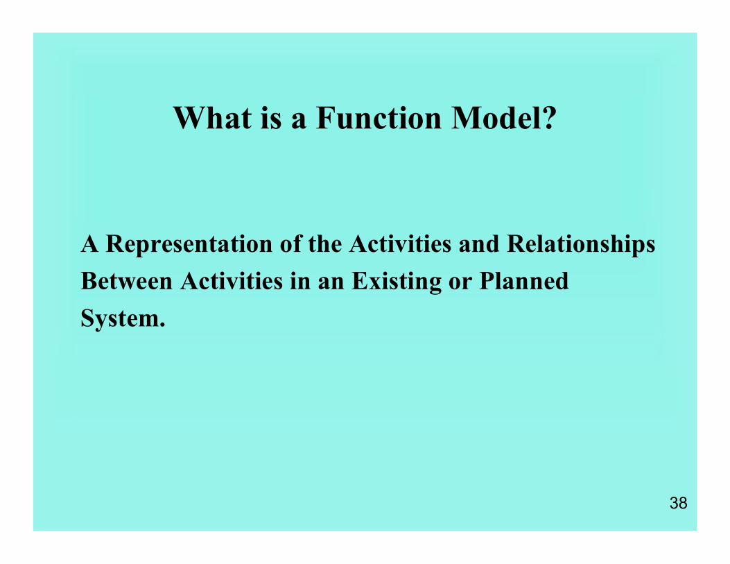
Bundles and Unbundles: PCB ASSEMBLY
Place chipon board
Applysolderpaste A2
Load boardonto m/c
A1
ManagementDirectives
Bare boards
Chip positioned board
placementcompleteddata
Placement method
Unbundle
Bundle
A3
Pasteappliedboard
Process Plan = loading details + solder paste details + chip placement method
Assembly Records = soldering completed data + placement completed data
Process plan
Solder pastemethod
solderingcompleteddata Assembly
Records

61
Function Decomposition
“Parent” Activities Represent a Higher Level of Abstraction than that of Their “Children”
A0
A0
A-0
A1
A2
A3
A4
Parent Diagram
Child Diagram
More General
More Detailed

62
Further Decomposition
Parent Activity
A0
A1
A2
A3
A4
A3
A32
A33
A34
A31
Child Diagram
Parent Diagram

63
Decomposition
• Establishes model hierarchy
• Functions are comprised of other functions
• Decompositions is a process of breaking down of the functions (level-by-level)
• Data consistency is required throughout the level-by-level decomposition breakdown

64
Complexity Simplification Technique
Tunneled Arrows
Tunneled Arrows at Unconnected Ends
(Concept Does Not Appear on the Next Higher Level.)
Tunneled Arrows at Connected Ends
(Concept Does Not Appear on the Next Lower Level.)

65
Tunneling Example
This control will not appearon child diagram.
This control will still be designated as C3 on child diagram.
This output will not be shownon parent diagram.
A0
A-0 Parent Diagram
A0
A1
A2
A3
C1 C3
O1
I1
Child Diagram

66
Steps in Building a Model
• 1. Define Viewpoint, Purpose, and Context
• 2. Develop the Context Diagram (Putting the situation in context)
• 3. Decompose activities to fit scope of modeling task (complete modeling per rules, etc)
• 4. Develop glossary

67
Model Orientation!!!!
• Context (Subject)The Boundaries of the Subject Matter
• Viewpoint (Bias)The Perspective from which a Subject is Analyzed
• Purpose (Objective)The Reason(s) a Model is Created

68
Example - Context Diagram
AcquireMaterials
Inventory Policy
Purchase policy
Stock Levels Payments
Rejected Materials
Vendor
ABC Co.
A0
A-0 Diagram

69
Example - Decomposition of the Context Diagram
A0 Diagram
Payments
Check Stock Levels & Det Reorder Qty
A1Prepare Authorize & Mail P O A2
Receive PO Produce & Ship A3
Receive Shipment & Inspect A4
Restock & Make Payment A5
Inventory Policy
Stock Levels
Reorder Qty
Purchase Policy
Invoice
Material OK Material
ABC Co. Vendor
Rejected Material
Purchase Order
PO Prep. Policy
Inspection Policy

70
IDEFØ Captures What an Enterprise Does

71
Why Develop An IDEFØ Activity Model?
To identify, document, and communicate an enterprise’s core activities.
To understand how activities relate to one another.
To identify value-added and non-value-added activities.
To identify activities that need to be improved.

72
Benefits of Activity Modeling
Documents current activities.
Reduces the learning curve for new activity users.
Captures and analyzes As-Is activities.
Facilitates the design/redesign of activities for To-Be scenarios.

73
An IDEFØ Activity Box
(what is produced by an activity, e.g., reports, products, etc.)
Inputs
Controls
Mechanisms
Function orActivity
(Verb Phase)
Outputs
(constraints on an activity, e.g., procedures, budgets, etc.)
(what enables an activity, e.g., equipment, personnel assignments, etc.)
(what is required before an activity can occur, e.g., purchase order, supervisor’s signature, etc.)

74
Context, Purpose, and Viewpoint:
The context defines the boundaries of your model—i.e., what will be included in the model.
For example, Employee/Position Data comes from outside the model.
PerformPersonnel
Actions
Applicant Data
Customer Request
Employee/PositionData
Personnel Action
Reports
Information System
Personnel Office Staff
Supplies & Equipment
Personnel Regulations
Department Policy
Supervisor Instructions
Manning Conditions

75
We define purpose as the reason to develop this particular activity model.
Purpose: To document the activities associated with managing Personnel Actions and identify non-value-added activities that might be eliminated.
Context, Purpose, and Viewpoint:
PerformPersonnel
Actions
Applicant Data
Customer Request
Employee/PositionData
Personnel Action
Reports
Information System
Personnel Office Staff
Supplies & Equipment
Personnel Regulations
Department Policy
Supervisor Instructions
Manning Conditions

76
Viewpoint can be thought of as the perspective of the person/group developing the model.
Context, Purpose, and Viewpoint:
Viewpoint:
Personnel Officer
PerformPersonnel
Actions
Applicant Data
Customer Request
Employee/PositionData
Personnel Action
Reports
Information System
Personnel Office Staff
Supplies & Equipment
Personnel Regulations
Department Policy
Supervisor Instructions
Manning Conditions

77
Maintain AccountsPayable
A0
Purchase request
Accounting staff
Company guidelines
Budget guidelines
Correct ledger
Payment
Decomposition: An Example

78
Process guidelinesProcess guidelines
Company guidelinesCompany guidelines
Invoice guidelinesInvoice guidelines
Processrequest
A1
A2
Processinvoice
Applypurchase to books
A3
Ledger guidelinesLedger guidelines
Purchase requestPurchase request
Accounting staffAccounting staff
PaymentPaymentInvoiceInvoice
Correct ledgerCorrect ledger
OrderOrder
Decomposition: An Example

79
Function Model for Planning and Implementing a Feat Ext module
• Purpose: To obtain a better understanding of the various tasks involved in planning and implementation of a feature extraction module
• Context: We will assume CAD model formats, process planning requirements and resources available (people and computers) are known. The FE module will be built using available existing resources (no new tools or software will be purchased).
• Viewpoint: that of an industrial / mfg engineer who has a background in designing / building software systems


![交通大學] system controller using modified IDEF0](https://img.pdfslide.us/doc/110x75/61688e43d394e9041f708c9c/-system-controller-using-modified.jpg)