Embed Size (px)
Citation preview
4
1
23
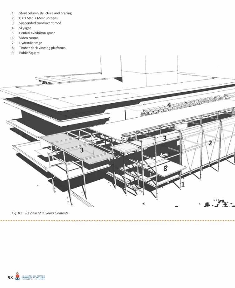
Steel column structure and bracing1. GKD Media Mesh screens2. Suspended translucent roof3. Skylight4. Central exhibiiton space5. Video rooms6. Hydraulic stage7. Timber deck viewing platforms8. Public Square9.
3
8
3D View of Building ElementsFig. 8.1.
98
7
6
5
9
08_ TECHNICAL INVESTIGATION
STRUCTUREThe structure comprises mostly of a primary steel structure of columns and beams with composite concrete floors. The steel struc-ture on the exterior of the building acts as a temporary exhibition space and has the ca-pacity to carry the load of temporary floors (constructed from light-weight materials). Steel members will be braced according to engineer’s specifications in all directions.A central stage/exhibition area protrudes from the main steel structure. This “stage” consists of a light-weight floor structure on six hydraulic lifting columns. They allow the stage to move up or down to allow better vis-ibility of performances from different areas in and around the new building.
TEMPORARY EXHIBITION SPACEThe building is orientated towards the public square to the west. This creates problems of unwanted heat gain on summer afternoons. A series of stainless steel mesh curtains with interwoven LED lamps are suspended from the external steel framework. These curtains act as shading devices to the restaurant and exhibition spaces, and act as large media screens to the public square. The patented mesh system will be discussed at length later in this chapter.
A light-weight translucent roof with a 1° pitch and with its highest point towards Sammy Marks Square, is suspended from the steel structure. This roof structure will cause large wind loads on the steel structure and will be securely tied back from both above and be-low through the use of steel cables.
GALLERYThe southern half of the building is a gal-lery. Natural ventilation is allowed through a system of folding/stackable doors that can be individually rotated. These doors consist of low UV-absorbent polycarbonate cellular panels in an aluminium frame. Each panel can be individually rotated to prevent direct sun-light from entering the building. Doors can be moved away to open the interior space com-pletely.
The upper floor of the gallery contains two video rooms that consist of coloured PAN-ELITE glass panels in fixed aluminium frames around the entire façade.
Cool air is allowed to move through louvered windows on the western façade of the dance studios on the third floor. Warm air is allowed to exit through a louvered skylight that forms a light well between the existing and new buildings.
TECHNICAL INVESTIGATION 99
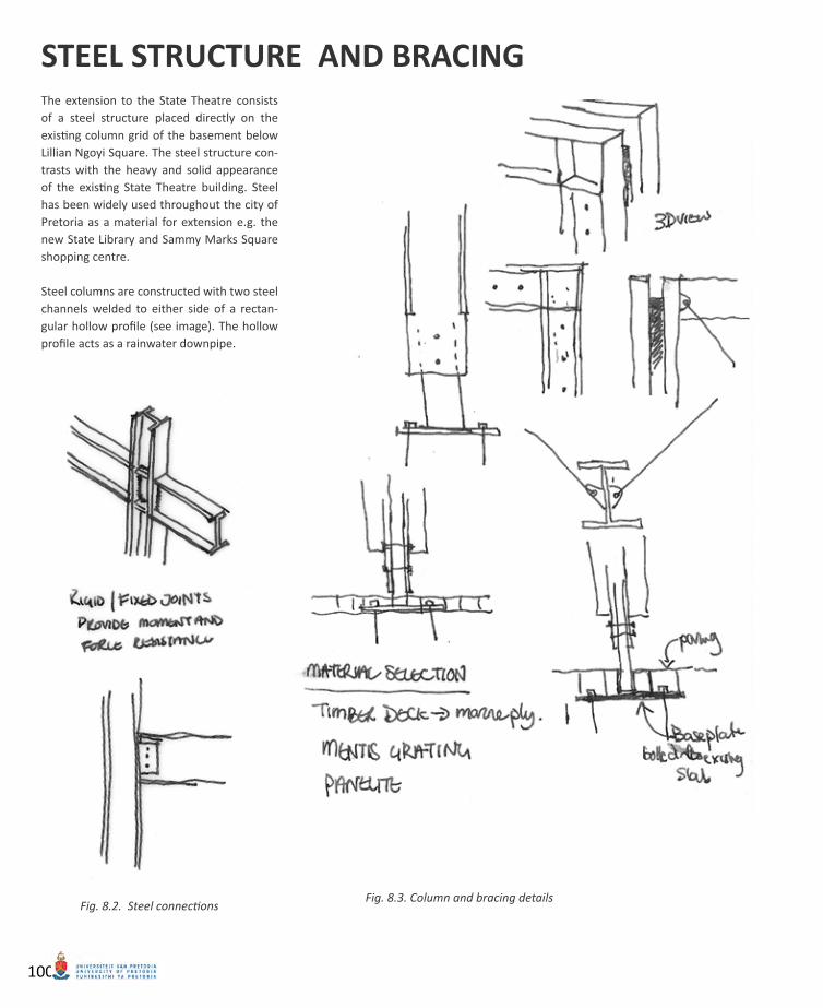
Column and bracing detailsFig. 8.3. Steel connectionsFig. 8.2.
The extension to the State Theatre consists of a steel structure placed directly on the existing column grid of the basement below Lillian Ngoyi Square. The steel structure con-trasts with the heavy and solid appearance of the existing State Theatre building. Steel has been widely used throughout the city of Pretoria as a material for extension e.g. the new State Library and Sammy Marks Square shopping centre.
Steel columns are constructed with two steel channels welded to either side of a rectan-gular hollow profile (see image). The hollow profile acts as a rainwater downpipe.
STEEL STRUCTURE AND BRACING
100
9150mm span
8540mm span
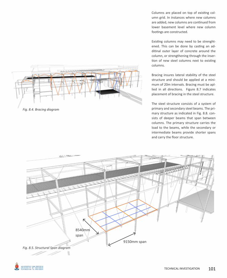
Columns are placed on top of existing col-umn grid. In instances where new columns are added, new columns are continued from lower basement level where new column footings are constructed.
Existing columns may need to be strenght-ened. This can be done by casting an ad-ditinal outer layer of concrete around the column, or strengthening through the inser-tion of new steel columns next to existing columns.
Bracing insures lateral stability of the steel structure and should be applied at a mini-mum of 20m intervals. Bracing must be apl-lied in all directions. Figure 8.7 indicates placement of bracing in the steel structure.
The steel structure consists of a system of primary and secondary steel beams. The pri-mary structure as indicated in Fig. 8.8. con-sists of deeper beams that span between columns. The primary structure carries the load to the beams, while the secondary or intermediate beams provide shorter spans and carry the floor structure.
Bracing diagramFig. 8.4.
Structural Span diagramFig. 8.5.
TECHNICAL INVESTIGATION 101
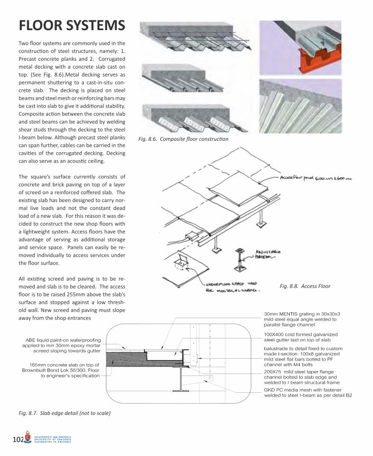
Slab edge detail (not to scale)Fig. 8.7.
Access FloorFig. 8.8.
Composite floor constructionFig. 8.6.
Two floor systems are commonly used in the construction of steel structures, namely: 1. Precast concrete planks and 2. Corrugated metal decking with a concrete slab cast on top. (See Fig. 8.6).Metal decking serves as permanent shuttering to a cast-in-situ con-crete slab. The decking is placed on steel beams and steel mesh or reinforcing bars may be cast into slab to give it additional stability. Composite action between the concrete slab and steel beams can be achieved by welding shear studs through the decking to the steel I-beam below. Although precast steel planks can span further, cables can be carried in the cavities of the corrugated decking. Decking can also serve as an acoustic ceiling.
The square’s surface currently consists of concrete and brick paving on top of a layer of screed on a reinforced coffered slab. The existing slab has been designed to carry nor-mal live loads and not the constant dead load of a new slab. For this reason it was de-cided to construct the new shop floors with a lightweight system. Access floors have the advantage of serving as additional storage and service space. Panels can easily be re-moved individually to access services under the floor surface.
All existing screed and paving is to be re-moved and slab is to be cleared. The access floor is to be raised 255mm above the slab’s surface and stopped against a low thresh-old wall. New screed and paving must slope away from the shop entrances
FLOOR SYSTEMS
102
HYDRAULIC STAGE SYSTEM
SQUARE ELEMENTS
Water feature detailFig. 8.9.
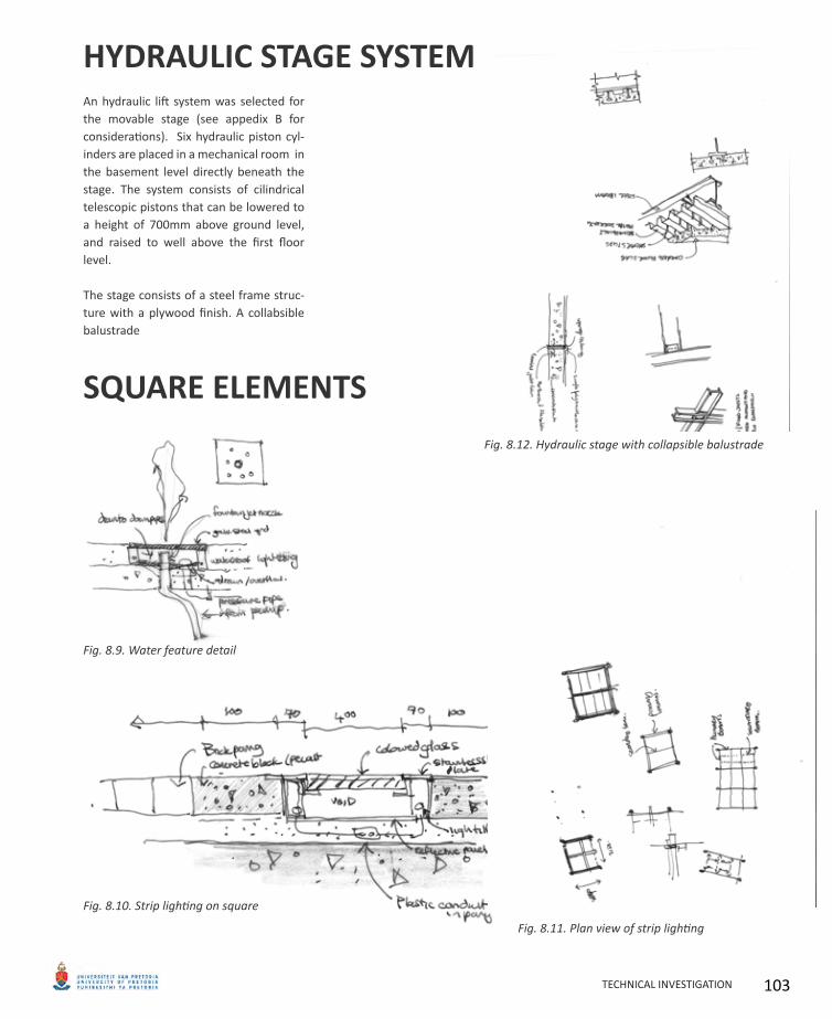
An hydraulic lift system was selected for the movable stage (see appedix B for considerations). Six hydraulic piston cyl-inders are placed in a mechanical room in the basement level directly beneath the stage. The system consists of cilindrical telescopic pistons that can be lowered to a height of 700mm above ground level, and raised to well above the first floor level.
The stage consists of a steel frame struc-ture with a plywood finish. A collabsible balustrade
Plan view of strip lightingFig. 8.11.
Strip lighting on squareFig. 8.10.
Hydraulic stage with collapsible balustradeFig. 8.12.
TECHNICAL INVESTIGATION 103
©20
08 P
AN
ELI
TE L
LC
NY
: 2
12.9
47.8
292
LA :
323
.297
.011
5 P
AN
EL
ITE
ww
w.p
anel
ite.u
s
02 Index03 User Guide04 Product Selector05 Laminated Series06 Bonded Series07 Cast Polymer 08 Mica Laminates 09 ClearShadeTM IGU10 IGU technical11 IGU technical12 IGU technical13 PFS System14 PFS details15 ITL System16 ITL details17 ITL details18 Sliding System19 Sliding System20 Custom Fabrication21 Contract Furniture22 Contact 23 Distribution
The Panelite ClearShadeTM insulating glass unit was developed for exterior glazing applications using a UV-stabilized tubular honeycomb core with patented polymer technology that offers superior shading performance. In addition to the benefits of visual privacy and a Visible Light Transmittance of up to 50%, the ClearShadeTM IGU achieves a Solar Heat Gain Coefficient of 0.18 at midday, approximately 75% lower than that of other insulating glass units without the need for tinted, reflective or specialty glass. This dramatically reduces climate control requirements and results in significant energy savings over the life of a building.
The ClearShadeTM IGU may be customized to meet a broad range of performance and aesthetic requirements.
PANEL COMPOSITIONSTANDARD UNIT COMPOSITION1” overall unit thicknessINBOARD LITE: 1/4” clear tempered glassINTERIOR: 1/2” airspace with Panelite ClearShadeTM honeycomb coreOUTBOARD LITE: 1/4” clear tempered glass
HONEYCOMB CORE OPTIONSCell Diameter: 1/4” standardStandard core thickness: 1/2”Standard Colors: Clear, Orange, Blue, Black, White, RedAll colors UV-stabilized. Custom color cores available for 1600 sqft. minimum order.
GLASS LITE FACING OPTIONSLaminated (1/4”, 5/16”, 3/8”, 7/16”, 1/2”, and 9/16”)Tempered (1/4”, 3/8”, and 1/2”)Custom colored PVB interlayer (laminated glass only).Standard Glass colors: bronze, grey, blue, green, and white Acid-etched, low-e coated glass, starphire low ironCeramic frit patterns
PANEL DIMENSIONSUnits are produced to specified dimensions per projectMaxiumum dimensions: 53” X 120”Panel thickness is subject to unit composition
MINIMUM ORDER800 SF for standard color units1600 SF for custom color core units
CLEARSHADETM IGU SERIES
PANELITETM IGU/TO4 • IIT McCormick Tribune Campus Center, Chicago IL • Design: OMA • Photography: Floto + Warner
PANELITE™ IGU/TC4 • INV Management • Design: Gluckman Mayner Architects • Photography: Panelite
PANELITE™ IGU/TO4 • Falcon Headquarters, Mexico City, Mexico • Design: Rojkind Arquitectos • Photography: Panelite
IGU/TC4
IGU/TO4
IGU/TW4
US Patent PendingPlease consult Panelite’s installation specifications under “product info” at www.panelite.us for complete handling, installation and technical information.
pg 09
IGU/TB4
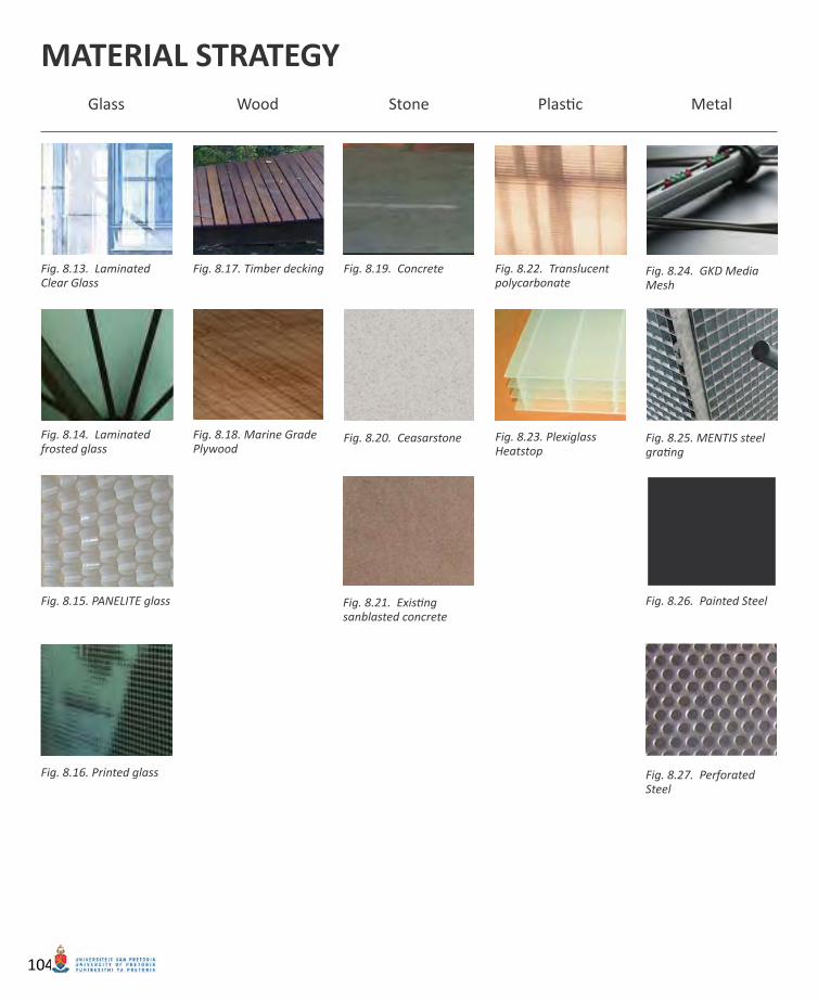
Glass Wood Stone Plastic Metal
Laminated Fig. 8.13. Clear Glass
Laminated Fig. 8.14. frosted glass
PANELITE glassFig. 8.15.
Printed glassFig. 8.16.
Timber deckingFig. 8.17.
Marine Grade Fig. 8.18. Plywood
ConcreteFig. 8.19.
CeasarstoneFig. 8.20.
Existing Fig. 8.21. sanblasted concrete
Translucent Fig. 8.22. polycarbonate
Plexiglass Fig. 8.23. Heatstop
GKD Media Fig. 8.24. Mesh
MENTIS steel Fig. 8.25. grating
Painted SteelFig. 8.26.
Perforated Fig. 8.27. Steel
MATERIAL STRATEGY
104
Material palettes of public buildings are generally required to be durable and easy to clean. The materials selected for the ex-tension of the State Theatre are displayed on the facing page arranged according to type. These materials were selected to create an effect of transparency.
The palette was selected to complement the existing theatre and surrounding buildings and give the building a high-tech appearance and contrast the old and new. Material consideration further included solar heat gain, durability, U value, and sustainability. Wood, Plastic and metals are recyclable. Glass products are strong and durable but will not be recyclable, however, they may be reusable.
GLASSThe brief requires a building that acts as a filter between the old and the new. Glass is used extensively throughout the project including staircase walls, lift shaft, parti-tioning panels, stairs and sliding walls.
The material acts as a filter material which allows the user a visual connection to the existing context without necessarily al-lowing a direct physical connection. Glass comes in a variety of finishes and options that will be discussed in this chapter.
Panelite (Fig.8.16) is an insulating glass unit that has been developed for exterior glazing applications. Panels consist of a UV-stabilized honey come core of polycar-bonate which allows the glass to act as a shading device. Panelite is available in a range of colours.
WOODTimber is a visually pleasing material which is warm to the touch. Timber slats is used throughout the building as sun-screens and sliding screens.
Timber decking is used on upper floor ex-hibition areas. Floor boards can be spaced
up to 10mm apart allowing water runoff though the boards and eliminating the need for drains and storm water channels. Plywood is used as a floor material on the movable stage. The material was selected for its durability and ability to last when exposed to sun and rain. Plywood is avail-able in large panels and can be used to create a large even surface which is ideal for dance floors.
STONEStone materials are hard and cold. Con-crete and stone was chosen for its durabil-ity and visual effect. The existing textured concrete facade of the Theatre is exposed celebrated.
Floors are constructed of concrete with a polished screen finish. This finish was chosen because of its durability as heavy sculptures and stage equipment may be moved around on the floor surface.
Ceasarstone is used for bar counters. The product is strong and easy to clean. It comes in a variety of colours and edge fin-ishes and is ideal for use as counter tops in kitchens and bars.
PLASTICBacklit polycarbonate sheeting can dis-perse light over a great distance, acting as a large light source while hiding unat-tractive light fittings. This material is hard wearing and can be recycled at the end of its usable life. Polycarbonate is used in restaurant areas as ceiling panels (see Fig.8.22).
Cellular polycarbonate sheeting (Fig.8.23) is used as material for the floor and door surfaces in the Gallery (Plexiglass HEAT-STOP), as well as a translucent screen in the restaurant and cafe spaces (plexiglass RESIST). Plexiglass HEATSTOP is a UV-ab-sorbing multi-skin cellular panel with a U-value of 4.4 and less for 12mm panels. This is an excellent rating which is compa-
rable to UV resistant glass.
METALGKD media mesh is used on the western facade as both a media screen to the pub-lic square, and a shading device to the restaurant/temporary exhibition space. These screens can act as an additional source of income as they could display ad-vertisements.
Steel grating is used as floor and wall sur-faces throughout the project. The mate-rial acts as a filter, a visual connection and free movement of air.
Steel columns are painted a dark grey colour and perforated steel is used for the underside of the translucent suspended roof in the gallery space. Perforated steel panels are used as a shading device as the underside of the suspended roof in the temporary exhibition space facing the public square.
TECHNICAL INVESTIGATION 105

Fig. 8.28. Fig. 8.29.
Fig. 8.30.
Fig. 8.31.
GKD MEDIA MESH
Advantages of media meshMaximum transparency is possible• Functions as both a media screen and a shading • device to a western façadeLong life and low energy consumption of LED lights• Pixel pitch can be chosen• Low maintenance• Can be used for the screening of media events• Can be used as a source of income as media • screens can be used for advertising
106
LED Media mesh curtains on the western façade serve as information screens to passers-by. They could serve as large screens on which live video feeds of the performances held on the stage may be displayed. On occasion, the square could act as a large outdoor cinema on hot summer nights. The Media mesh system is a transparent media screen system consisting of GKD stainless steel wire mesh with interwoven LED lights. LEDs are only visible from one side (the public square), while the mesh acts as a shading device that protects the restaurant/café spaces from the harsh western sun. With up to 90% transparency, the mesh maintains a visual link between the square and the restaurant and bal-cony spaces.
GKD Media Mesh is available in three different options; namely Me-dia Mesh (with the Tigris type mesh), PC media mesh (a modified rod mesh) and Illumesh, which is merely a coloured and illuminated façade that cannot display a clear image.
Greater distance from the media mesh curtains allows a better resolu-tion of the image displayed; therefore, the mesh is best viewed from the seating/steps provided on the edges of the square. Pixel pitch is adjustable and resolution of the image displayed depends on the spac-ing of LEDs. A higher resolution is equal to greater cost.
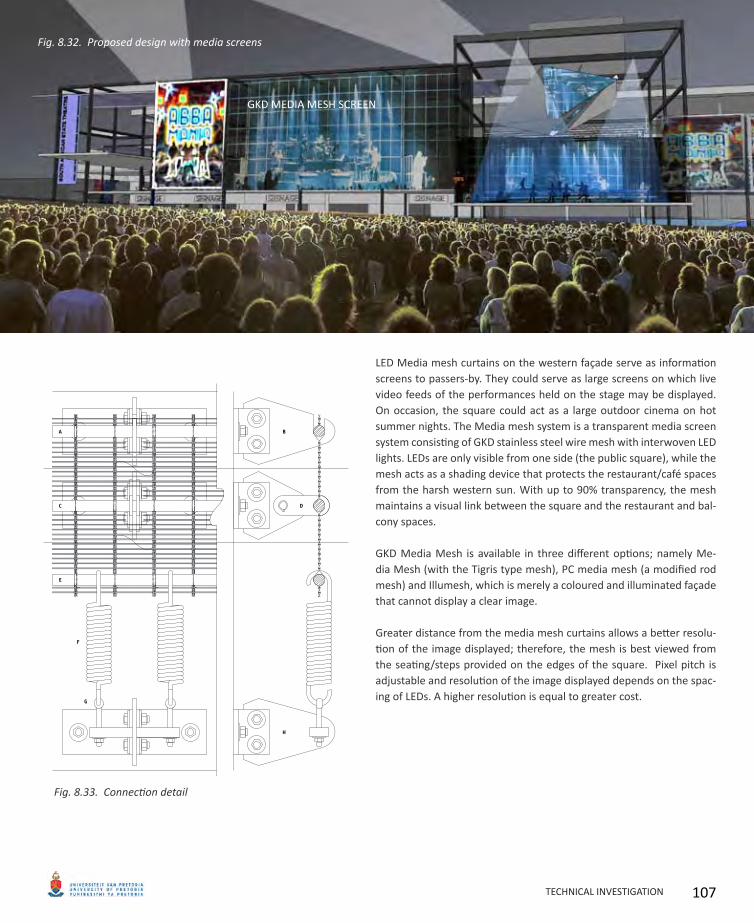
Connection detailFig. 8.33.
Proposed design with media screensFig. 8.32.
GKD MEDIA MESH SCREEN
TECHNICAL INVESTIGATION 107
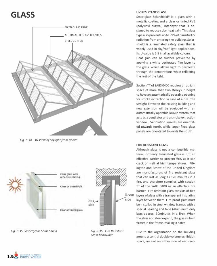
AUTOMATED GLASS LOUVRES
STEEL GUTTER
GLASS UV RESISTANT GLASSSmartglass Solarshield® is a glass with a metallic coating and a clear or tinted PVB (polyvinyl butyral) interlayer that is de-signed to reduce solar heat gain. This glass type also prevents up to 99% of harmful UV radiation from entering the building. Solar-shield is a laminated safety glass that is widely used in sky/roof-light applications. Its U-value is 5.8 in all available colours.Heat gain can be further prevented by applying a white perforated film layer to the glass, which allows light to permeate through the penetrations while reflecting the rest of the light.
Section TT of SABS 0400 requires an atrium space of more than two storeys in height to have an automatically operable opening for smoke extraction in case of a fire. The skylight between the existing building and new extension will be equipped with an automatically operable louvre system that acts as a ventilator and a smoke extraction window. Ventilation louvres are orientat-ed towards north, while larger fixed glass panels are orientated towards the south.
FIRE RESISTANT GLASSAlthough glass is not a combustible ma-terial, ordinary laminated glass is not an effective barrier to prevent fire, as it can crack or melt at high temperatures. Pilk-ington and Schott of the United Kingdom are manufacturers of fire resistant glass that can last as long as 120 minutes in a fire, and therefore complies with section TT of the SABS 0400 as an effective fire barrier. Fire resistant glass consists of two layers of glass with a transparent insulating layer between them. Fire-proof glass must be installed in steel window frames with a special beading and tape (Aluminium only lasts approx. 30minutes in a fire). When the glass and steel expand, the glass is held firmer in the frame, making it safer.
Due to the organization on the building around a central double volume exhibition space, an exit on either side of each sec-
3D View of skylight from aboveFig. 8.34.
Fire Resistant Fig. 8.36. Glass behaviour
Smartgralls Solar ShieldFig. 8.35.
FIXED GLASS PANEL
108
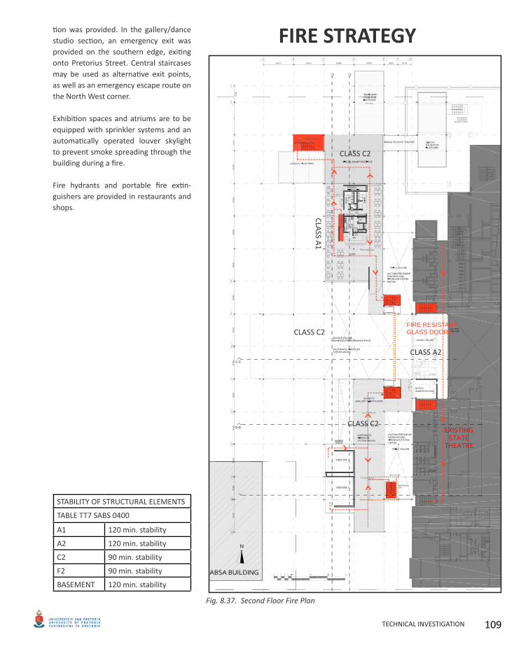
tion was provided. In the gallery/dance studio section, an emergency exit was provided on the southern edge, exiting onto Pretorius Street. Central staircases may be used as alternative exit points, as well as an emergency escape route on the North West corner.
Exhibition spaces and atriums are to be equipped with sprinkler systems and an automatically operated louver skylight to prevent smoke spreading through the building during a fire.
Fire hydrants and portable fire extin-guishers are provided in restaurants and shops.
FIRE STRATEGY
STABILITY OF STRUCTURAL ELEMENTS
TABLE TT7 SABS 0400
A1 120 min. stability
A2 120 min. stability
C2 90 min. stability
F2 90 min. stability
BASEMENT 120 min. stability
FIRE RESISTANT GLASS DOORS
Second Floor Fire PlanFig. 8.37.
CLASS C2
CLASS C2
CLASS C2
CLASS A2
CLASS A
1
TECHNICAL INVESTIGATION 109
PANELITE CLEARSHADE CELLULAR INSULATED GLASS
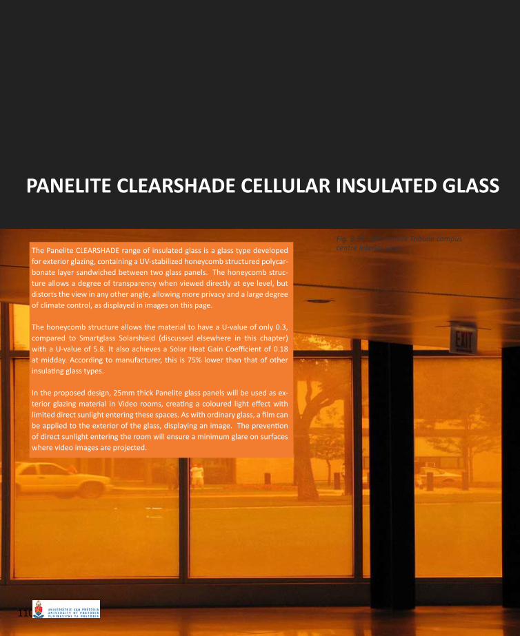
The Panelite CLEARSHADE range of insulated glass is a glass type developed for exterior glazing, containing a UV-stabilized honeycomb structured polycar-bonate layer sandwiched between two glass panels. The honeycomb struc-ture allows a degree of transparency when viewed directly at eye level, but distorts the view in any other angle, allowing more privacy and a large degree of climate control, as displayed in images on this page.
The honeycomb structure allows the material to have a U-value of only 0.3, compared to Smartglass Solarshield (discussed elsewhere in this chapter) with a U-value of 5.8. It also achieves a Solar Heat Gain Coefficient of 0.18 at midday. According to manufacturer, this is 75% lower than that of other insulating glass types.
In the proposed design, 25mm thick Panelite glass panels will be used as ex-terior glazing material in Video rooms, creating a coloured light effect with limited direct sunlight entering these spaces. As with ordinary glass, a film can be applied to the exterior of the glass, displaying an image. The prevention of direct sunlight entering the room will ensure a minimum glare on surfaces where video images are projected.
McCormick Tribune campus Fig. 8.38. centre interior view.
110
©20
08 P
AN
ELI
TE L
LC
NY
: 2
12.9
47.8
292
LA :
323
.297
.011
5 P
AN
EL
ITE
ww
w.p
anel
ite.u
s
02 Index03 User Guide04 Product Selector05 Laminated Series06 Bonded Series07 Cast Polymer 08 Mica Laminates 09 ClearShadeTM IGU10 IGU technical11 IGU technical12 IGU technical13 PFS System14 PFS details15 ITL System16 ITL details17 ITL details18 Sliding System19 Sliding System20 Custom Fabrication21 Contract Furniture22 Contact 23 Distribution
The Panelite ClearShadeTM insulating glass unit was developed for exterior glazing applications using a UV-stabilized tubular honeycomb core with patented polymer technology that offers superior shading performance. In addition to the benefits of visual privacy and a Visible Light Transmittance of up to 50%, the ClearShadeTM IGU achieves a Solar Heat Gain Coefficient of 0.18 at midday, approximately 75% lower than that of other insulating glass units without the need for tinted, reflective or specialty glass. This dramatically reduces climate control requirements and results in significant energy savings over the life of a building.
The ClearShadeTM IGU may be customized to meet a broad range of performance and aesthetic requirements.
PANEL COMPOSITIONSTANDARD UNIT COMPOSITION1” overall unit thicknessINBOARD LITE: 1/4” clear tempered glassINTERIOR: 1/2” airspace with Panelite ClearShadeTM honeycomb coreOUTBOARD LITE: 1/4” clear tempered glass
HONEYCOMB CORE OPTIONSCell Diameter: 1/4” standardStandard core thickness: 1/2”Standard Colors: Clear, Orange, Blue, Black, White, RedAll colors UV-stabilized. Custom color cores available for 1600 sqft. minimum order.
GLASS LITE FACING OPTIONSLaminated (1/4”, 5/16”, 3/8”, 7/16”, 1/2”, and 9/16”)Tempered (1/4”, 3/8”, and 1/2”)Custom colored PVB interlayer (laminated glass only).Standard Glass colors: bronze, grey, blue, green, and white Acid-etched, low-e coated glass, starphire low ironCeramic frit patterns
PANEL DIMENSIONSUnits are produced to specified dimensions per projectMaxiumum dimensions: 53” X 120”Panel thickness is subject to unit composition
MINIMUM ORDER800 SF for standard color units1600 SF for custom color core units
CLEARSHADETM IGU SERIES
PANELITETM IGU/TO4 • IIT McCormick Tribune Campus Center, Chicago IL • Design: OMA • Photography: Floto + Warner
PANELITE™ IGU/TC4 • INV Management • Design: Gluckman Mayner Architects • Photography: Panelite
PANELITE™ IGU/TO4 • Falcon Headquarters, Mexico City, Mexico • Design: Rojkind Arquitectos • Photography: Panelite
IGU/TC4
IGU/TO4
IGU/TW4
US Patent PendingPlease consult Panelite’s installation specifications under “product info” at www.panelite.us for complete handling, installation and technical information.
pg 09
IGU/TB4
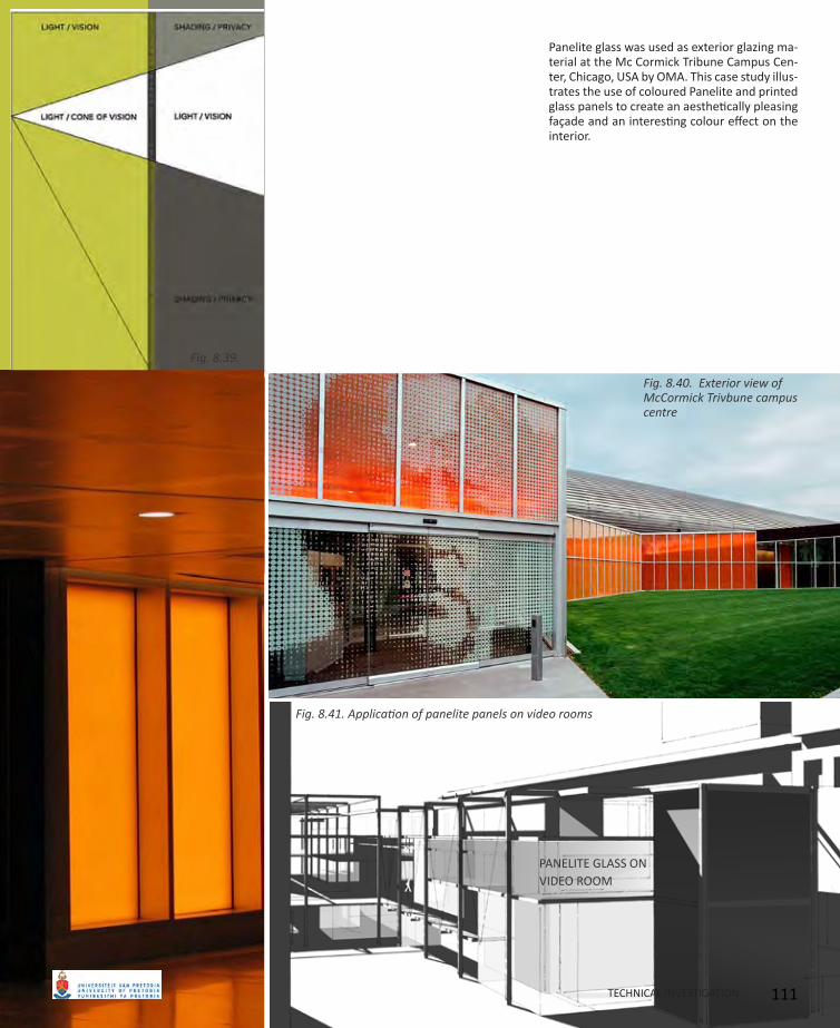
Panelite glass was used as exterior glazing ma-terial at the Mc Cormick Tribune Campus Cen-ter, Chicago, USA by OMA. This case study illus-trates the use of coloured Panelite and printed glass panels to create an aesthetically pleasing façade and an interesting colour effect on the interior.
Fig. 8.39.
Exterior view of Fig. 8.40. McCormick Trivbune campus centre
Application of panelite panels on video roomsFig. 8.41.
PANELITE GLASS ON VIDEO ROOM
TECHNICAL INVESTIGATION 111
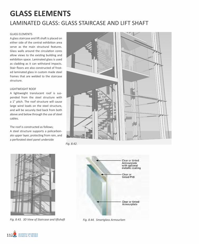
GLASS ELEMENTSA glass staircase and lift shaft is placed on either side of the central exhibition area serve as the main structural features. Glass walls around the circulation cores allow views to the existing building and exhibition space. Laminated glass is used as cladding as it can withstand impacts. Stair floors are also constructed of frost-ed laminated glass in custom made steel frames that are welded to the staircase structure.
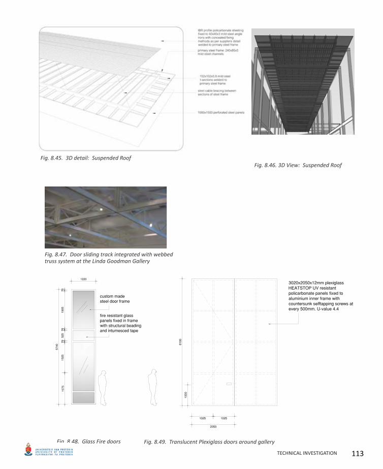
LIGHTWEIGHT ROOFA lightweight translucent roof is sus-pended from the steel structure with a 1° pitch. The roof structure will cause large wind loads on the steel structure, and will be securely tied back from both above and below through the use of steel cables.
The roof is constructed as follows; A steel structure supports a policarbon-ate upper layer, protecting from rain, and a perforated steel panel underside
GLASS ELEMENTSLAMINATED GLASS: GLASS STAIRCASE AND LIFT SHAFT
Fig. 8.42.
3D View of Staircase and liftshaftFig. 8.43. Smartglass ArmourlamFig. 8.44.
112
LAMINATED GLASS: GLASS STAIRCASE AND LIFT SHAFT
3D detail: Suspended RoofFig. 8.45. 3D View: Suspended RoofFig. 8.46.
Door sliding track integrated with webbed Fig. 8.47. truss system at the Linda Goodman Gallery
Glass Fire doorsFig. 8.48. Translucent Plexiglass doors around galleryFig. 8.49.
TECHNICAL INVESTIGATION 113
GREEN STRATEGIES
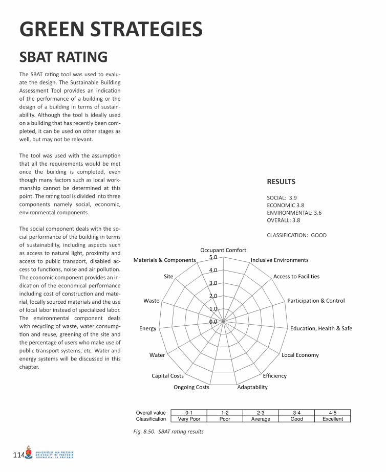
The SBAT rating tool was used to evalu-ate the design. The Sustainable Building Assessment Tool provides an indication of the performance of a building or the design of a building in terms of sustain-ability. Although the tool is ideally used on a building that has recently been com-pleted, it can be used on other stages as well, but may not be relevant.
The tool was used with the assumption that all the requirements would be met once the building is completed, even though many factors such as local work-manship cannot be determined at this point. The rating tool is divided into three components namely social, economic, environmental components.
The social component deals with the so-cial performance of the building in terms of sustainability, including aspects such as access to natural light, proximity and access to public transport, disabled ac-cess to functions, noise and air pollution. The economic component provides an in-dication of the economical performance including cost of construction and mate-rial, locally sourced materials and the use of local labor instead of specialized labor. The environmental component deals with recycling of waste, water consump-tion and reuse, greening of the site and the percentage of users who make use of public transport systems, etc. Water and energy systems will be discussed in this chapter.
RESULTS
SOCIAL: 3.9ECONOMIC 3.8ENVIRONMENTAL: 3.6OVERALL: 3.8
CLASSIFICATION: GOOD
SBAT RATING
Instructions
Objective
The objective of the tool is to provide an indication of the performance of a building or the design of a building in terms of sustainability
Scope
The tool should be ideally be used on a building that has just been completed.
It can be used at other stages of a building's lifecycle but some criteria may not be relevant
The tool can be used on most building types such as schools, housing and offices, conventionally used by people to live and work in
Instructions
Step One Setting the Project Up
Complete the project and assessment sections of the A. Report section
Refer to definitions below
Step Two Entering Measurements
Complete each of the sections B. Social, C. Economic and D. Environmental
Under the column Measured indicate the percentage compliance from 0 to 100 % for each of the relevant criteria
If you do not have the information required for the criteria enter O%
Should you have any queries about criteria, refer to Notes adjacent to the criteria
Should you wish to make limited comments please note these in red under the Notes section
Detailed technical performance information on your building should be entered direcly into the powerpoint accommpanying this document
Step Three Reading the Report
On completion return to the A. Report section. The spidergraph should now have filled and values should have appeared in all boxes.
Social provides an indication of the social performance of the building in terms of sustainability
Economic provides an indication of the economic performance of the building in terms of sustainability
Environmental provides an indication of the environmental performance of the building in terms of sustainability
Overall provides an indicatotion of the overall building performance in terms of sustainability
To rate the building use the scale below and enter the relevant building classification (Very Poor to Excellent)
Overall value 0-1 1-2 2-3 3-4 4-5
Classification Very Poor Poor Average Good Excellent
Definitions
Occupied Space: Space that is normally used by people for living or working in
User: People who regularly use the building
Contact
Should you wish to comment on this tool, please contact:
Jeremy Gibberd, FPM, CSIR
Tel: 012 841 2839 Fax: 012 841 3504
Email: [email protected]
SBAT rating resultsFig. 8.50.
114
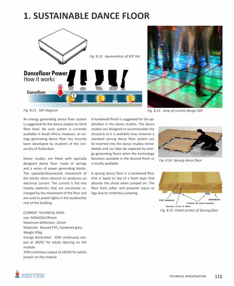
An energy generating dance floor system is suggested for the dance studios on third floor level. No such system is currently available in South Africa, however, an en-ergy generating dance floor has recently been developed by students of the Uni-versity of Rotterdam.
Dance studios are fitted with specially designed dance floor made of springs and a series of power generating blocks. The upwards/downwards movement of the blocks when danced on produces an electrical current. The current is fed into nearby batteries that are constantly re-charged by the movement of the floor and are used to power lights in the studios/the rest of the building
CURRENT TECHNICAL DATA:size: 650x650x195mmMaximum deflection: 10mmMaterials: Reused PVC, hardened glassWeight 45kgEnergy Generated: 10W continuous out-put at 18VDC for adults dancing on the module.20W continious output at 18VDV for adults jumpin on the module
A hardwood finish is suggested for the ap-plication in the dance studios. The dance studios are designed to accommodate the structure as it is available now, however a standard sprung dance floor system can be inserted into the dance studios imme-diately and can later be replaced by ener-gy generating floors when the technology becomes available in the desired finish or is locally available.
A sprung dance floor is a hardwood floor that is layed on top of a foam layer that absorbs the shock when jumped on. The floor feels softer and prevents injury to legs due to continious jumping.
1. SUSTAINABLE DANCE FLOOR
SDF diagramFig. 8.51.
Axonometric of SDF tileFig. 8.52.
View of current design SDFFig. 8.53.
Sprung dance floorFig. 8.54.
Detail section of Sprung floorFig. 8.55.
TECHNICAL INVESTIGATION 115
2. VENTILATION STRATEGY
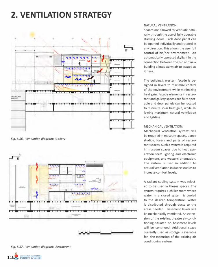
Ventilation diagram: GalleryFig. 8.56.
Ventilation diagram: RestaurantFig. 8.57.
NATURAL VENTILATION:Spaces are allowed to ventilate natu-rally through the use of fully operable stacking doors. Each door panel can be opened individually and rotated in any direction. This allows the user full control of his/her environment. An automatically operated skylight in the connection between the old and new building allows warm air to escape as it rises.
The building’s western facade is de-signed in layers to maximize control of the environment while minimizing heat gain. Facade elements in restau-rant and gallery spaces are fully oper-able and door panels can be rotated to minimize solar heat gain, while al-lowing maximum natural ventilation and lighting.
MECHANICAL VENTILATION:Mechanical ventilation systems will be required in museum spaces, dance studios, foyers and parts of restau-rant spaces. Such a system is required in museum spaces due to heat gen-eration form lighting and electronic equipment, and western orientation. The system is used in addition to natural ventilation in dance studios to increase comfort levels.
A radiant cooling system was select-ed to be used in theses spaces. The system requires a chiller room where water in a closed system is cooled to the desired temperature. Water is distributed through ducts to the areas needed. Basement levels will be mechanically ventilated. An exten-sion of the existing theatre air-condi-tioning situated on basement levels will be continued. Additional space currently used as storage is available for the extension of the existing air conditioning system.
116
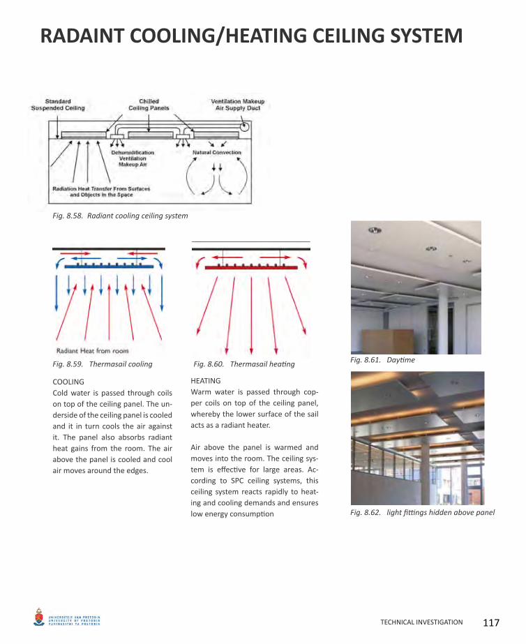
RADAINT COOLING/HEATING CEILING SYSTEM
HEATINGWarm water is passed through cop-per coils on top of the ceiling panel, whereby the lower surface of the sail acts as a radiant heater.
Air above the panel is warmed and moves into the room. The ceiling sys-tem is effective for large areas. Ac-cording to SPC ceiling systems, this ceiling system reacts rapidly to heat-ing and cooling demands and ensures low energy consumption
COOLINGCold water is passed through coils on top of the ceiling panel. The un-derside of the ceiling panel is cooled and it in turn cools the air against it. The panel also absorbs radiant heat gains from the room. The air above the panel is cooled and cool air moves around the edges.
Radiant cooling ceiling systemFig. 8.58.
Thermasail coolingFig. 8.59. Thermasail heatingFig. 8.60. DaytimeFig. 8.61.
light fittings hidden above panelFig. 8.62.
TECHNICAL INVESTIGATION 117
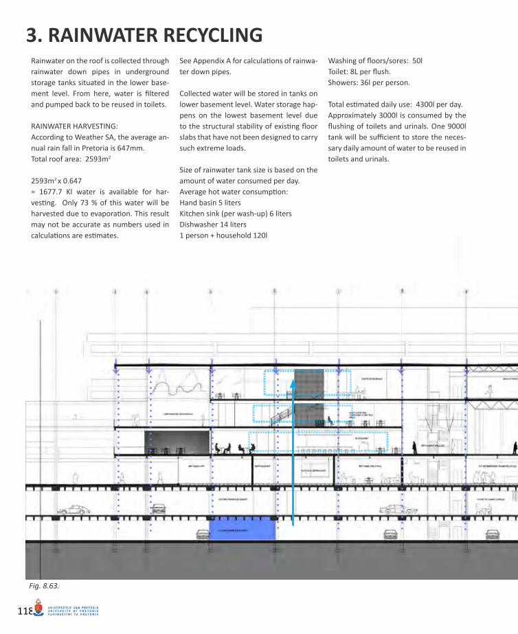
Rainwater on the roof is collected through rainwater down pipes in underground storage tanks situated in the lower base-ment level. From here, water is filtered and pumped back to be reused in toilets.
RAINWATER HARVESTING:According to Weather SA, the average an-nual rain fall in Pretoria is 647mm. Total roof area: 2593m2
2593m2 x 0.647= 1677.7 Kl water is available for har-vesting. Only 73 % of this water will be harvested due to evaporation. This result may not be accurate as numbers used in calculations are estimates.
See Appendix A for calculations of rainwa-ter down pipes.
Collected water will be stored in tanks on lower basement level. Water storage hap-pens on the lowest basement level due to the structural stability of existing floor slabs that have not been designed to carry such extreme loads.
Size of rainwater tank size is based on the amount of water consumed per day.Average hot water consumption: Hand basin 5 litersKitchen sink (per wash-up) 6 litersDishwasher 14 liters1 person + household 120l
Washing of floors/sores: 50lToilet: 8L per flush.Showers: 36l per person.
Total estimated daily use: 4300l per day.Approximately 3000l is consumed by the flushing of toilets and urinals. One 9000l tank will be sufficient to store the neces-sary daily amount of water to be reused in toilets and urinals.
3. RAINWATER RECYCLING
Fig. 8.63.
118
TECHNICAL INVESTIGATION 119
09_ CONCLUSION
120
This thesis has investigated principles in the design of successful public spaces in order to find a solution to the possible improvement of an existing public square in Pretoria, namely Lil-lian Ngoyi Square. Despite the square’s prime location within the city, the lack of interaction between the square and its surroundings had caused a lack of activity on the square.
The design has provided a possible solution to the improvement of the quality of the square by breaking down physical and imaginary bound-aries between the theatre and the public. This has been achieved by providing a western “bal-cony” and a new entrance to the theatre, that opens onto the public square. The design has attempted to create a more inclusive public space that would invite visitors to enjoy and ex-perience life in the city. It has also attempted to provide a comfortable and safe public space for visitors to rest and enjoy people-watching.
The design has proposed an outdoor theatre and a number of street cafes opening onto the square that would enhance the image and tour-ist value of the public space. Further, the design has suggested the improvement of pedestrian access and an easier transition between the square and the surrounding streets.
The building was intended to be a filter that would create a transition between the formal theatre and the informal public square. The purpose has been for the building to draw new visitors to the site and to educate the man on the street about the arts and the opportunities provided by the State Theatre. The concept of a filter has been drawn through the urban de-sign to the detail level of design and all building elements. Materials were specifically chosen to give the “filter” effect that would allow visual access, or a physical connection. The transpar-ency of the structural frame was intended to be a skeleton from which the stage and decoration could be constructed during concerts and for temporary exhibitions. The scheme has pro-vided the opportunity for investment into the future of the theatre as a factory of the per-forming arts.
121TECHNICAL INVESTIGATION