Embed Size (px)
Citation preview
2002/10 (Ver.1) (Discharging)3- 1
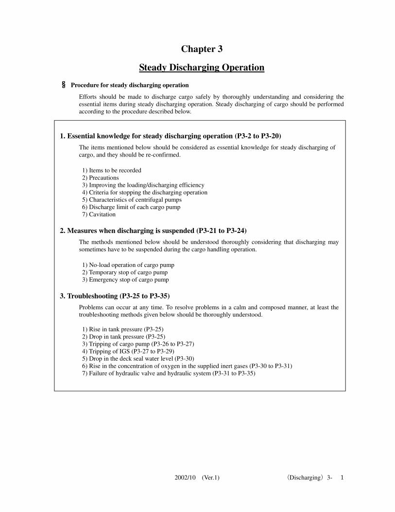
Chapter 3
Steady Discharging Operation
§§§§ Procedure for steady discharging operation
Efforts should be made to discharge cargo safely by thoroughly understanding and considering the
essential items during steady discharging operation. Steady discharging of cargo should be performed
according to the procedure described below.
1. Essential knowledge for steady discharging operation (P3-2 to P3-20)
The items mentioned below should be considered as essential knowledge for steady discharging of
cargo, and they should be re-confirmed.
1) Items to be recorded 2) Precautions 3) Improving the loading/discharging efficiency 4) Criteria for stopping the discharging operation 5) Characteristics of centrifugal pumps 6) Discharge limit of each cargo pump 7) Cavitation
2. Measures when discharging is suspended (P3-21 to P3-24)
The methods mentioned below should be understood thoroughly considering that discharging may
sometimes have to be suspended during the cargo handling operation.
1) No-load operation of cargo pump 2) Temporary stop of cargo pump 3) Emergency stop of cargo pump
3. Troubleshooting (P3-25 to P3-35)
Problems can occur at any time. To resolve problems in a calm and composed manner, at least the
troubleshooting methods given below should be thoroughly understood.
1) Rise in tank pressure (P3-25) 2) Drop in tank pressure (P3-25) 3) Tripping of cargo pump (P3-26 to P3-27) 4) Tripping of IGS (P3-27 to P3-29) 5) Drop in the deck seal water level (P3-30) 6) Rise in the concentration of oxygen in the supplied inert gases (P3-30 to P3-31) 7) Failure of hydraulic valve and hydraulic system (P3-31 to P3-35)
2002/10 (Ver.1) (Discharging)3- 2
1. Inspections, checks and records during the steady discharging operation
1.1 Items to be checked and recorded
Click here to view video – 026.mp4
1.1.1 During steady discharging, the items mentioned below should be monitored at all times to
confirm that no abnormality exists. The said items should be recorded every hour.
1) Pump rpm 2) Pump discharge pressure (CCR) 3) Pump suction pressure (CCR) 4) Manifold pressure 5) Draft 6) Ullage (of all tanks) 7) Pressure (of all tanks) 8) P/V breaker water level 9) Discharging capacity 10) Discharging rate 11) Pump flow rate 13) Concentration of oxygen in the supplied IG (confirm that this is less than 5%) 14) Direction and distance of buoy and condition of mooring system (any abnormality?) when ship is
moored at the SPM/SBM berth (SPM: Single Point Mooring/SBM: Single Buoy Mooring;
hereafter referred to as SPM) 15) Position of Chiksan arm and condition of mooring system (any abnormality?) during berthing 16) Wind direction and wind speed
1.1.2 The items below should be measured and recorded at least once every hour.
1) Pump discharge pressure 2) Pump suction pressure 3) Pump casing temperature 4) Pump bearing temperature 5) Any abnormality in the pump room?
1.2 General Precautions
1) Check the pressure of each tank at least once every hour and confirm that it is being regulated at
the predetermined pressure during the discharging operation. At this stage, also compare the IG
main line pressure and the P/V breaker water level and confirm that there is no abnormality. 2) During parallel operation of two or more pumps, there is sometimes a "defeated" pump. Monitor
this pump according to the judgment method, and if necessary, adjust the pump rpm or the
discharge pressure. (Refer to "3.3.4 the phenomenon of “defeated” during parallel operation" on
P2-25 of the "Discharging Section.") 3) During the discharging operation, the ullage becomes large, differences arise in the oil levels in
various tanks, and as a result, various phenomena occur in the cargo pumps in operation. If the
pump is not operated (within the operating range) to cope with the changes in level, the discharging
efficiency reduces and cavitation occurs leading to pump damage. This point should be carefully
noted. Efforts should be made to avoid cavitation *20
and the pump should be operated correctly
when cavitation occurs. Cavitation can be easily detected when it occurs since the discharge and
suction pressures vary, giving rise to large noise and vibrations. However, measures should be
adopted promptly. If no action is taken against cavitation, it becomes difficult to continue operation,
and in the worst case, the pump may be damaged. (Refer to "1.6.2 Measures to be adopted when
cavitation occurs" on P3-11 of the "Discharging Section.") 4) Precautions should be taken to guard against overheating of the casing or vapor lock
*21 during
no-load operation of the pump when discharging is suspended. 5) Care should be taken against the occurrence of water hammer, which is the main cause of pump
damage. Scrupulous care is necessary to ensure that oil flows in the suction line during cargo pump
operation. If the suction valve is closed by mistake, high negative pressure may occur
2002/10 (Ver.1) (Discharging)3- 3
instantaneously and the pump may trip due to overspeed simultaneously. If the suction valve is
opened in haste, the pump may be damaged due to the water hammer effect that appears immediately.
6) As discharging progresses, the oil level reduces leading to a reduction in the suction pressure. As a
result, the discharge flow rate reduces, the line resistance reduces and therefore, the manifold
pressure also reduces even if the pump rpm does not change When the manifold pressure reduces as
discharging progresses, it is to be noted that the pump rpm should be raised in order to maintain the
manifold pressure (to maintain the required flow rate). 7) Flow should be maintained in the suction line in order to strictly adhere to the allowable flow
velocity in the pipe (6 m/sec.) for the butterfly valve. Suction valves of one or more tanks should be
fully opened for discharging oil cargo using one pump after referring to the allowable flow velocity
in the pipeline.
* Checking the recording system
The CCR watch should check the automatic recording of oxygen concentration of the IGS and the tank
pressures, and confirm that the system is working correctly based on the records entered on the record
sheets. For instance, let us take the case of zigzag, ridged curves due to load fluctuations on the record sheet
for oxygen concentration. If this curve is a straight line, then the oxygen concentration gauge is
probably abnormal. This can be adjusted by comparing with a portable oxygen concentration gauge on
site. Similarly, the tank pressure repeatedly overshoots the predetermined pressure immediately after IGS
operation. Over time, the pressure stabilizes at the predetermined pressure. Thus, these records enable
confirmation of correct functioning of the system. *20 What is cavitation?
During pump operation, the pressure of the flow near the impeller entrance reduces locally. If the
absolute pressure is equal to or less than the saturated vapor pressure of the liquid at that temperature,
the liquid in that part starts vaporizing even if no heat is applied, and gas bubbles are created. The phenomenon of occurrence of gas bubbles in the liquid is called cavitation. When cavitation occurs,
the discharge pressure or the suction pressure varies, noise and vibrations increase, and the operation
can no longer be continued. Cavitation leads to pump damage such as erosion, and to the shortening of
pump life.
*21 What is vapor lock?
The oil in the pump casing gradually gets heated up due to impact with the impeller during its rotation.
As the oil temperature rises, it vaporizes, and a condition similar to racing due to vapor suction occurs.
This phenomenon is called vapor lock. This vapor lock can lead to tripping of pump, strain due to high temperatures, and burn-out of the
impeller, bearing or gland packing.
1.3 Improving loading/discharging efficiency
The discharging time is influenced significantly by the ship's attitude (trim, list) and the difference in
levels of various tanks during the discharging operation. The basic items mentioned below should be
thoroughly understood for discharging cargo oil efficiently.
a) Trim b) List c) Ullage differences among the discharging tanks
In such a case, it is necessary to first close the discharge valve, reduce the pump rpm to minimum rpm and then
stop the pump. To eliminate the negative pressure, gradually open the air cock of the pump to obtain atmospheric
pressure within the line. Although the tank gas pressure in the cargo tank should be used to obtain positive
pressure If valve lineup to obtain positive pressure using tank gas pressure is not possible, then use of the air
cock should also be considered.
2002/10 (Ver.1) (Discharging)3- 4
d) Features and functions of slop tank
1.3.1 Trim
Click here to view video – 027.mp4
1) Immediately after starting the operation, "discharge uniformly" the cargo from tanks without
trimming the vessel. Regardless of draft restrictions, the tanks to be discharged are discharged evenly by about 2 to 3 m
at the same time, avoiding the complex operations immediately after starting the discharging
operation. This operation is called "discharging uniformly." If oil is not discharged uniformly,
especially at a discharging site with draft restrictions, the trim increases and there is a risk of the
ship's bottom touching the sea bed. 2) When the ship is trimmed, care should be taken against overflow.
If the ship is trimmed to an appreciable extent when the tanks are full (98% of the tank capacity),
and if the watertightness of hatches, Butterworth openings and ullage openings of tanks to be
discharged are unsatisfactory due to poor maintenance, there is a risk of gas spewing out or oil
leaking out due to localized pressure. Safety measures should be adopted considering the
maximum aft trim as about 6 m when the tanks are fully loaded. 3) Guidelines for planning trim are given below.
After "discharging uniformly" the cargo by 2 to 3 m, the tank valve should be adjusted such that
the anticipated aft trim is obtained gradually while ensuring that the draft restriction is not
exceeded. During the initial stage of discharging, a large aft trim may not be required but a trim of
more than 4 m is required during stripping of the tank, and where possible, a 6-m trim should be
ensured bearing in mind that other tanks may be fully loaded. In a VLCC, the increase in head
pressure from the No. 1 tank at an aft trim of 6 m is about 0.3 MPa (about 0.3 kg/cm2).
4) The hull strength should be considered when the vessel is to be trimmed. Trim adjustments should be made while monitoring and ensuring hull strength by entering the
latest data in the computer and carrying out ballasting work in parallel. In most cases, the planned
trim should be obtained by ballasting. 5) The general relationships between basic piping arrangement and trim in a tanker are as given
below. a) Gas lines are installed forward of the upper deck tanks, and gas main and stripping bell mouth are
installed at the aftermost part within the tanks. b) The IG branch valve and the breather valve fitted to the tank are installed at the forward part of
the tank, and are arranged considering their use in adjusting trim by the stern. Consequently,
special care is necessary for trim by the head. In practice, tanks cannot be stripped with a forward trim. Therefore, the problem of forward trim
is resolved when formulating the discharging plan. c) The main and stripping bell mouths in the cargo tank are installed at the aftermost part of the tank,
designed so as to achieve optimum stripping with an aft trim. However, in some ships, these may
be installed in the forward part of the tank near the center of the tank bottom because of the tank
shape as in the 5P/S and SLOP P/S tanks. In such tanks, the bell mouth is installed in the lowest
part of the tank bottom considering the tank structure. In these tanks, optimum stripping cannot be
achieved with a large aft trim. Therefore, the installed positions of the bell mouths should be
confirmed on the final drawing.
1.3.2 List (heel)
1) If the ship is heeled to a large extent when berthing it, the fenders on the terminal are likely to be
damaged. Care should be taken to prevent a heel greater than 1.0 degree (difference in draft at
port/starboard about 100 cm). (Precautions for mooring lines should be taken when heeling the ship during berthing.)
2) The ship may be heeled using ballast so that optimum stripping is obtained after studying the
arrangement of the stripping bell mouths in the tanks, but the heel may need to be adjusted using
cargo, depending on the operation. 3) Generally, two kinds of stripping bell mouth arrangements may be used.
2002/10 (Ver.1) (Discharging)3- 5
a) Bell mouths arranged on the port side of the tank in the starboard and center tanks, and arranged
on the starboard side of the tank in the port side tank. In this case, the starboard and center tanks can be efficiently stripped if the ship is heeled to port,
and port tank can be efficiently stripped if the ship is heeled to starboard. b) Bell mouths arranged on the port side in all the tanks
In this case, all tanks can be efficiently stripped if the ship is heeled to port. This arrangement is
adopted in the Takasago Maru. The ship can be heeled easily as desired if the port side slop tank is
taken as the final tank to be discharged.
1.3.3 Ullage difference among the discharging tanks After discharging uniformly the cargo (ullage of 2 to 3 m), the tank valves should be adjusted to trim
the ship by aft. The difference in levels of forward and aft cargo oil tanks should be generally about 1
to 2 m, but the difference in levels in the No. 1 cargo oil tank and the No. 5 cargo oil tank (without slop
tank) should be taken as approximately 2 to 4 m. In principle, oil should be discharged fully from the
forward cargo oil tank first. That is, the closer the tank to the aft cargo oil tank, the larger is the volume
of oil the tank holds. The items mentioned below related to tank valve adjustments should be
thoroughly understood before performing the adjustments.
1) For the same pipe diameter, the pipe with the shorter length has smaller resistance. 2) The smaller the piping resistance and closer the tank is to the pump, the greater is the suction flow
rate. The above implies that the closer the tank to the aft cargo oil tank, the greater is the throttling of
the tank valve during steady discharging operation.
1.3.4 Characteristics of the slop tank
1) In principle, cargo tanks are unpainted except tank bottom, but slop tanks are painted with tar
epoxy coating. 2) The capacity of slop tank is 3% greater than the capacity of the cargo tank. The slop tank is
designed as a small tank with large depth. Not only is oil/water segregation easy, but very little
water remains after discharging the tank. 3) The washing oil suction is fitted about 2 m above the bottom of the tank and designed such that
moisture (antistatic measures adopted) and impurities such as sludge are not sucked in. 4) Where ballast water or washing water that has been settled, is passed through the ODM (Oil
Discharge Monitoring and Control System) and discharged legally in accordance with rules and
regulations, oily water above the regulated value is recovered in the slop tank automatically.
1.3.5 Functions of the slop tank
1) Used as washing oil delivery tank during crude oil washing work and as a collection tank for
stripped oil.
2) Also used as an eductor-driven oil tank and collection tank and used for stripping tanks other than
slop tanks. To minimize the drop in discharging efficiency of the cargo pump during the
discharging operation, change over to stripping the tank with the eductor before the level in the
tank to be discharged drops and before discharging with the cargo pump becomes severe. The
discharging efficiency using the cargo pump can be improved if small oil is led from other tanks
with high liquid level through the main valves of these tanks. 3) Used as a header tank for preventing cavitation.
Oil is collected in the slop tank using the tank cleaning pump and negative pump suction pressure
is reduced by means of discharge small amount of oil concurrently from the slop tank while
maintaining a safe and steady level (generally an ullage of 10 m) as suction pressure for the
collecting oil by the tank cleaning pump. If crude oil washing is not carried out at the final stage of
discharging, the cargo handling time can be curtailed by this method.
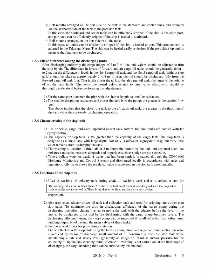
The washing oil suction is fitted about 2 m above the bottom of the tank and designed such that impurities
such as sludge are not sucked in. There is the ship as not fitted suction above such design.
2002/10 (Ver.1) (Discharging)3- 6
4) When gas is sucked into the cargo pump and operation becomes unstable at the final stage of
discharging, the suction line up to the pump is primed using the slop head. The capacity of the bottom line of the cargo main is about 100 m
3 per line.
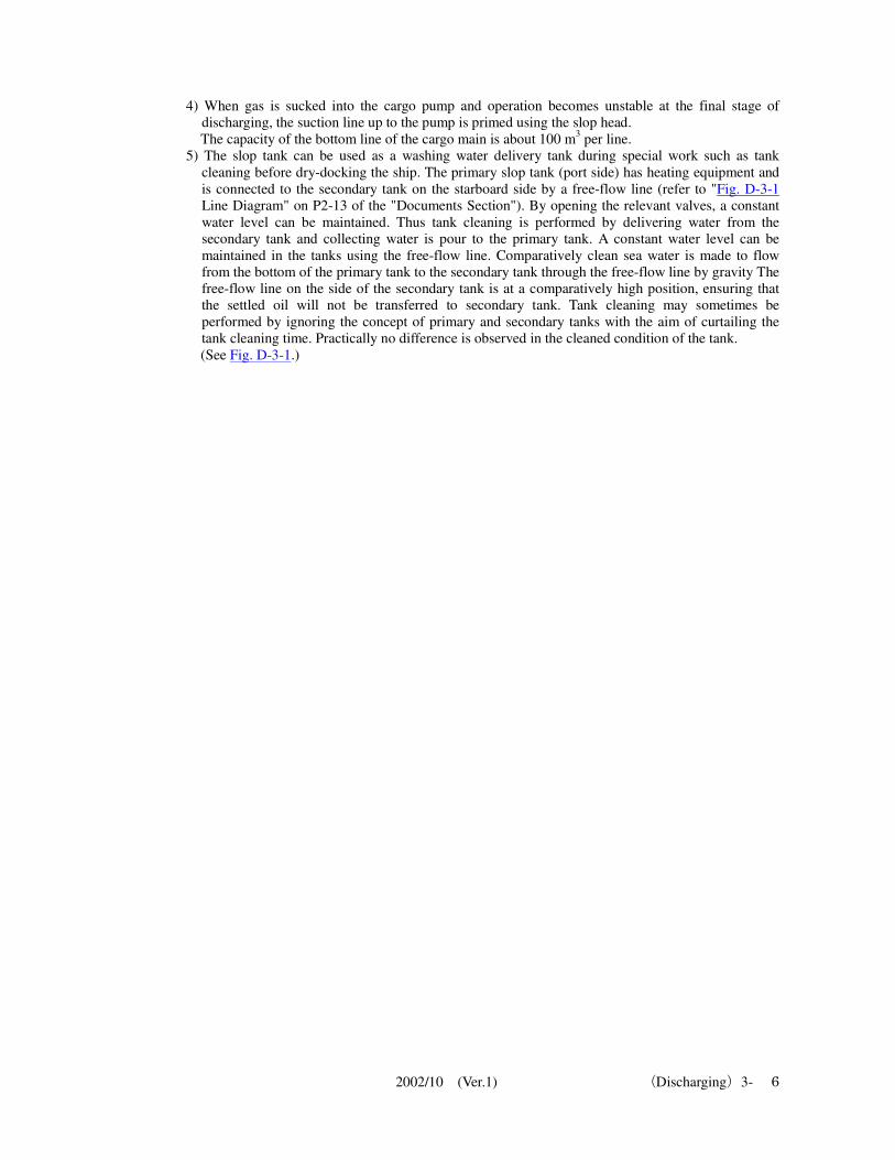
5) The slop tank can be used as a washing water delivery tank during special work such as tank
cleaning before dry-docking the ship. The primary slop tank (port side) has heating equipment and
is connected to the secondary tank on the starboard side by a free-flow line (refer to "Fig. D-3-1
Line Diagram" on P2-13 of the "Documents Section"). By opening the relevant valves, a constant
water level can be maintained. Thus tank cleaning is performed by delivering water from the
secondary tank and collecting water is pour to the primary tank. A constant water level can be
maintained in the tanks using the free-flow line. Comparatively clean sea water is made to flow
from the bottom of the primary tank to the secondary tank through the free-flow line by gravity The
free-flow line on the side of the secondary tank is at a comparatively high position, ensuring that
the settled oil will not be transferred to secondary tank. Tank cleaning may sometimes be
performed by ignoring the concept of primary and secondary tanks with the aim of curtailing the
tank cleaning time. Practically no difference is observed in the cleaned condition of the tank. (See Fig. D-3-1.)
2002/10 (Ver.1) (Discharging)3- 7
2002/10 (Ver.1) (Discharging)3- 8
1.4 Discharge limit of each cargo pump
When discharging cargo oil from a full-load cargo tank on the ship to a shore tank with low oil level,
the cargo pump may sometimes be running in the overload condition, well above the rated operating
condition. If the pump is operated continuously for a long period in this condition, it may be damaged
therefore, precautions are necessary.
1.4.1 Pump operation
When the tank level is high, the discharge pressure of the cargo pump is low (back pressure (=total
discharge head*22
)is low) and the pump rpm is raised, the discharge flow rate easily and significantly
exceeds the rated flow rate even if the pump rpm is below the rated rpm. This indicates that the cargo
pump's performance curves have been exceeded. If the pump is operated for a long period in a
condition where the performance curves are exceeded, overload and cavitation may occur depending on
the liquid level, leading to pump damage. Precautions are necessary to avoid raising the pump rpm
excessively when the discharge pressure is low.
1.4.2 Pump discharge rate
The discharge rate per cargo pump during the discharging operation should be restricted to the
designated flow rate even if the suction head is adequately large. Precautions are particularly necessary when the flow rate at the terminal reception facility exceeds the
capacity of the cargo pump on the ship. When the pump is running at a high rpm, high discharge
pressure, the discharge valve is fully open, and the designated flow rate is exceeded, it is not a good
plan to reduce the delivery valve opening to adjust flow rate and perform adjustments by the reducing
rpm of the pump. (Refer to "1.7.2 Operating points and flow rate adjustments of centrifugal pump" on P3-18 of the
"Discharging Section.")
1.4.3 Pump operation at the rated rpm
When the suction pressure is normal there is no risk of cavitation, and The pump may be operated at
the rated rpm only the case is ensured such that the suction pressure is ensured adequately without no
risk of cavitation and the discharge pressure can be maintained enough high even if the delivery valve
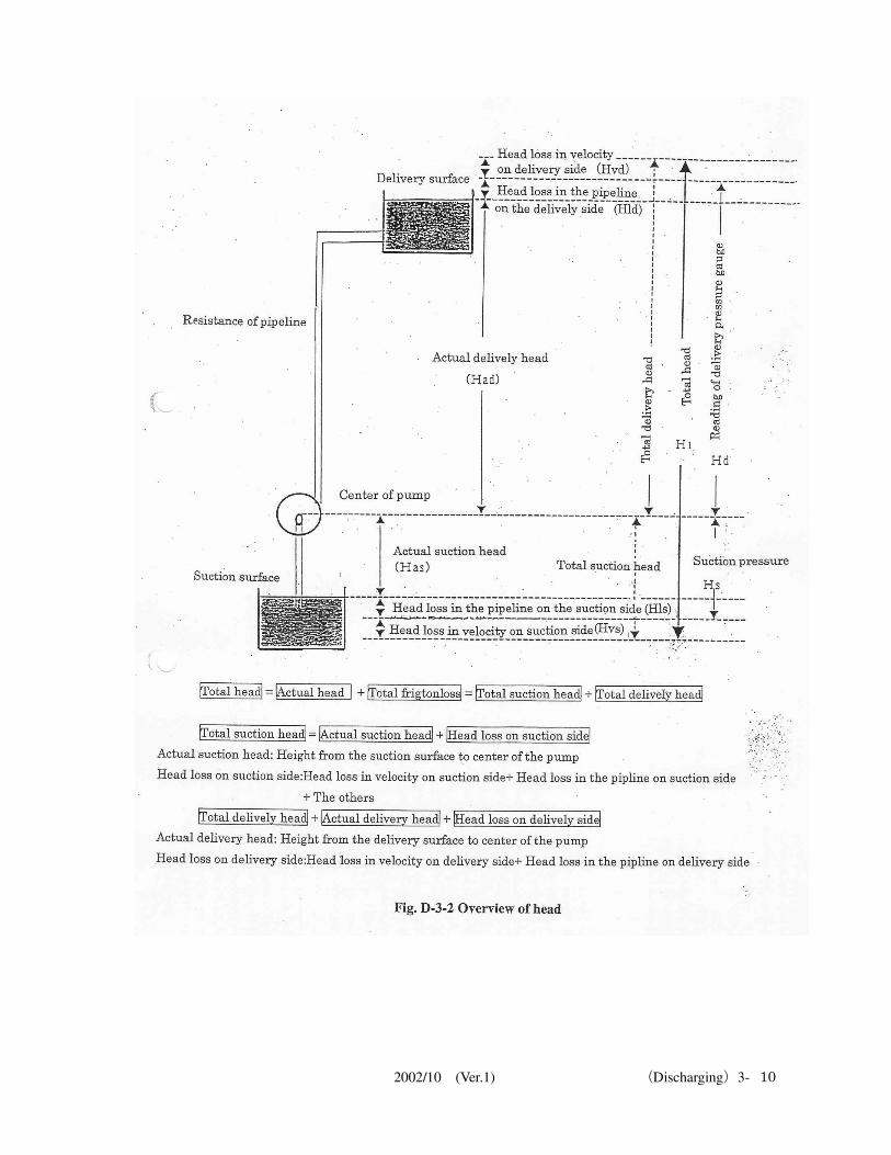
opened fully and the total head is more than 90% of the rated head. *22 What is head? (See Fig. D-3-2)
A pump is a machine that transfers liquid continuously from a low (low pressure) location to a high
(high pressure) location. This requires the pump to overcome various kinds of resistance. This
resistance is called lift or head of water. Head may of five types mentioned below.
1) Actual head The vertical distance from the suction surface to the surface to be discharged is called actual head.
2) Velocity head Energy proportional to the flow velocity is required for the liquid to flow. This energy is called
velocity head and it is shown in the same units as the water head. If velocity head is ignored, then pump suction pressure is approximately equal to suction tank head
pressure minus suction line resistance. The relationship between flow rate and resistance is:
"Resistance is directly proportional to the square of the flow rate and the pipe length when the pipe
diameter is constant." Thus, if the suction line remains the same, the pump suction pressure
reduces as the suction flow rate increases. 3) Pressure head
Pressure head is the mean of atmospheric pressure which is exposed for all objects on the earth's
surface. When calculate the pressure in the tank,you should consider that the suction surface in the
tank is pressurized by inert gas. 4) Head loss in pipeline
Resistance exists between liquid and pipe when a liquid flows in a pipe. Moreover, the flowing
liquid also has to overcome its own resistance when it causes turbulence. This resistance is called
loss head in pipeline. Bends in the pipeline, branching points, changes in pipe diameter and various

2002/10 (Ver.1) (Discharging)3- 9
valves constitute a large resistance. 5) Total head
The sum of the heads from 1) to 4) is called total head.
2002/10 (Ver.1) (Discharging)3- 10
2002/10 (Ver.1) (Discharging)3- 11
1.5 Criteria for stopping the discharging operation
Discharging should be stopped when the conditions mentioned below occur.
1) Oxygen concentration in the tank exceeds 8% by volume. 2) If supply is no longer possible because of failure of the inert gas system 3) If the pressure within the tank has dropped below +1.961 kPa (+200 mmAq) 4) If the charterer or the terminal has specified restrictions on oxygen concentration that are stricter
than the criteria given above, then those restrictions take priority.
1.6 Cavitation
1.6.1 Occurrence of cavitation The pump should be operated correctly during the discharging operation before cavitation occurs.
Cavitation can be easily detected when it occurs since noise and vibrations increase. It should be borne
in mind that if appropriate measures against cavitation are not adopted, continuous operation becomes
difficult, and in the worst case, the pump may be damaged. (Refer to "*20 What is cavitation?" on P3-3
of the "Discharging Section.") 1.6.2 Measures to be adopted when cavitation occurs
The measures below are required to be adopted when cavitation occurs.
1) Reduce the pump rpm. 2) Throttle the discharge valve. 3) If there is a tank with head, open the suction valve of the tank and reduce the negative pressure.
That is, if the eductor can be used, the oil should be collected in the slop tank to develop the head.
The suction valve in the slop tank should be opened to some extent (usually about 30%, but this
may be changed depending on the condition) to ensure the pump suction pressure. 4) Increase the number of suctions tanks using the stripping line. In this case, oil should have been
filled in the stripping line before connect the line to the main line. It is important to have the line used for discharging fully filled with oil during the pump priming
work so that it can be readily used whenever required.
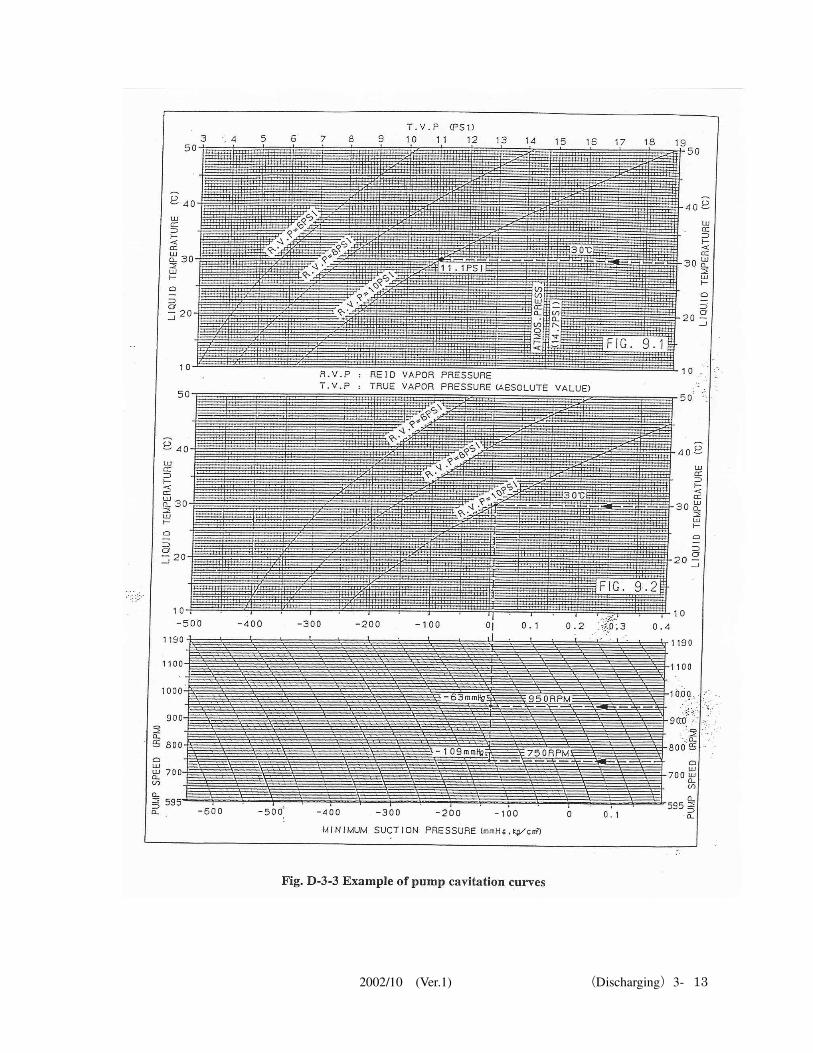
1.6.3 Cavitation occurrence limit (refer to Fig. D-3-3 for an example of pump cavitation curves)
Cavitation occurs within the pump under the condition as:
1) When Av. NPSH*24
= required NPSH The cavitation occurrence limit is:
2) Av. NPSH = Req. NPSH Consequently,
3) Suction pressure = (Req. NPSH x spec. gravity ÷ 10) + (saturated vapor pressure) < absolute
pressure: kgf/cm2.>
a) The gauge pressure is:
Gauge pressure = (absolute pressure) - (atmospheric pressure) = (absolute pressure) - (1.033) b) For mercury column (mmHg) indication, since atmospheric pressure (1.033 kgf/cm
2) is equivalent
to a mercury column of 760 mmHg, we get: mmHg = (Gauge pressure) x (760/1.033) c) For water head indication (m): Head (m) = (Gauge pressure) ÷ (specific weight) < kgf/m
3>
d) To obtain the pressure in SI units: kPa = (Gauge pressure) x (101.3/1.033) e) Atmospheric pressure = 1.033 kgf/cm
2 = 101.3 kPa = 760 mmHg = 1 atm
(CGS units) (SI units) (mercury column) (1 atmosphere) f) Differences between density, specific weight and specific gravity
(1) Density (ρ): Mass per unit volume Units are kg/m
3, kg/cm
3, g/cm
3
(2) Specific weight (γ): Weight per unit volume (weight expressed in terms of force)

2002/10 (Ver.1) (Discharging)3- 12
Units are in kgf/m3
(3) Specific gravity (SG): Comparison with water No units
2002/10 (Ver.1) (Discharging)3- 13
2002/10 (Ver.1) (Discharging)3- 14
1.6.4 NPSH (Net Positive Suction Head) NPSH should be understood thoroughly if cavitation is to be prevented. The occurrence of cavitation
within the pump depends on whether the lowest pressure of the liquid flowing in the pump (the part
immediately after the impeller entrance is the part with the lowest pressure) is higher or lower than the
saturated vapor pressure of the liquid. The suction head is used to determine whether cavitation occurs,
but using the Net Positive Suction Head is more convenient than using the suction head. There are two
kinds of NPSH.
1)Av. NPSH
*23( Available NPSH ): Available net positive suction head
This is equivalent to the result of subtracting the saturated vapor pressure at the liquid temperature
from the total suction head at the center of the impeller.
Av. NPSH = (Total suction head) - (saturated vapor pressure) * When atmospheric pressure acts on the suction surface during suction: Av. NPSH = (Atmospheric pressure) - (actual suction head) - (head loss on suction side) - (saturated
vapor pressure) < Head loss on suction side: losses in pipeline and velocity > Av. NPSH = H0 – Has – Hls – Hvs – Hvp … Head indication = ( 10 P2 / Sg ) + ( Vs
2 / 2g ) – ( 10 Pvp / Sg )
Where,
H0 :Atmospheric pressure
Has :Actual suction head …. Height from the suction surface to the center of the pump
Hls : Head loss in the pipeline on the suction side
Hvs : Head loss in velocity on the suction side
Hvp : Saturated vapor pressure
P2 : Suction pressure (kgf/cm2: absolute pressure) = H0 -Has -Hls
Vs2 / 2g : Loss on the suction side expressed as suction velocity
Pvp : Saturated vapor pressure indication … 10Pvp/Sg becomes head = Hvp
When atmospheric pressure acts on and presses against the suction surface Av. NPSH = (Atmospheric pressure) + (actual suction head) - (head loss on suction side) - (saturated
vapor pressure)
Av. NPSH = H0 + Has – Hls – Hvs – Hvp … Water head/lift indication
= ( 10 P2 / Sg ) + ( Vs2 / 2g ) – ( 10 Pvp / Sg ) * Suction pressure indication is the same although the notation of Has is different.
2) Req. NPSH *24
( Required NPSH ) : Net positive suction head required
Local pressure drop (∆h) occurs immediately after the pump impeller entrance but the liquid does not
vaporize due to this pressure drop. This is the head required for pumping.
Req. NPSH = ∆h + (Vs2/2g) ≒ ∆h
* Since Vs2/2g is very small, it can be ignored.
* ∆h: The liquid flowing from the impeller entrance to the interior brings about changes in the velocity
and direction of flow according to the shape of the impeller blades. The maximum pressure drop occurs
in the vicinity immediately after the impeller entrance.
*23 What is Av. NPSH?
It is the value of net suction head and is determined by the actual head on the pump suction side,
various conditions of pipelines, flow velocity and saturated vapor pressure. That is, its value varies
depending on the degree of opening of the suction valve and the type of the liquid used.
*24 What is Req. NPSH?
Its value is determined by the shape of the impeller and the flow rate (rpm, flow velocity).
2002/10 (Ver.1) (Discharging)3- 15
1.6.5 Determination of suction pressure that does not cause cavitation (concrete example) Since cavitation occurs when Av. NPSH ≦ Req. NPSH, it can be prevented by either increasing Av.
NPSH or by decreasing Req. NPSH.
1) Conditions
With the conditions of Reid vapor pressure of crude oil at 37.8 °C equal to 0.33 kgf/cm2, specific
weight of 850 kgf/m3 and Req. NPSH of discharging flow rate of cargo pump equal to 4.5 m, let us
determine the suction pressure required for operating the cargo pump so that no cavitation occurs. 2) Condition for cavitation not to occur
Av. NPSH > Req. NPSH
3) Suction pressure Suction pressure = (Req. NPSH X specific gravity ÷ 10) + (Reid vapor pressure) … absolute
pressure: kgf/cm2 < It is convenient to use Reid vapor pressure instead of saturated vapor pressure for crude oil >
P2 = (4.5×0.85÷10 ) + 0.33 = 0.7125 kgf/cm2 ata (or A or abs) Absolute pressure
* Specific gravity of crude oil = Specific weight of crude oil/Specific weight of water = 850/1000
= 0.85 4) Gauge pressure
Gauge pressure = (Absolute pressure) - (atmospheric pressure) = 0.7125 – 1.033
= - 0.3205 kgf/cm2G
5) Mercury column indication mmHg = (Gauge pressure) X(760/1.033)
= - 0.3205 × 760 ÷ 1.033
= - 235.8 mmHg
6) Crude oil height indication Crude oil height (m) = (Gauge pressure) ÷ (Specific weight)
= - 0.3205 × 10000 ÷ 850 … (in meter units)
=- 3.77 m
* Suction is possible up to this height (height of crude oil surface from the center of the pump) 7) SI units indication kPa = (Gauge pressure) x (101.3/1.033)
= - 0.3205 × 101.3 ÷ 1.033
= - 31.43 kPa G
1.7 Centrifugal (volute) pump characteristics
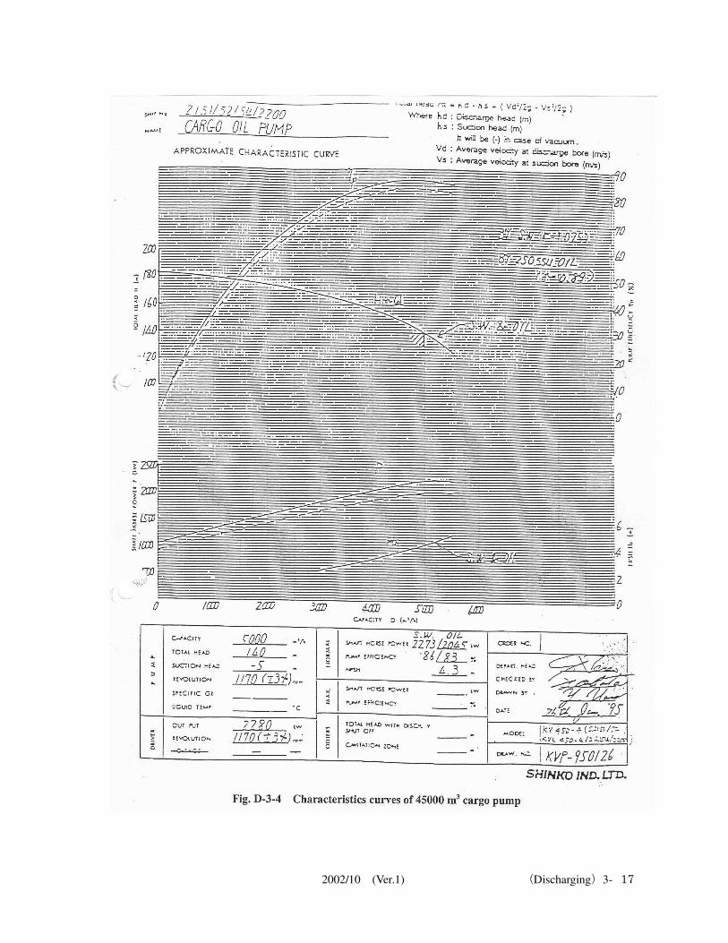
1.7.1 Performance curves of centrifugal pump The performance curves of the centrifugal pump are explained here, based on the characteristic curves
shown in Fig. D-3-4.
1) Pump performance at rated rpm
A steam turbine is the primer mover of this pump. When the pump is operating at the ratings below,
maximum efficiency is indicated. (1) Rpm: 1,170 (±3%) (2) Pressure head on suction side: -5 m (3) Total head: 140 m (4) Capacity: 5,000 m
3/h
(5) Output: 2,280 kW (6) Shaft power: 2,045 kW
2) Performance curves The performance curves mentioned below are included in the characteristic curves.
(1) Total head curves (H~Q) The discharge rate of the centrifugal pump reduces when the head increases. Conversely, if the
head decreases, the discharge rate increases. When the discharge valve is throttled to obtain a high head in tankers, the discharge capacity
2002/10 (Ver.1) (Discharging)3- 16
reduces with the increase in the head. This can be determined from the head curves. When the pump is operating at the rated rpm, the total head is 140 m and the discharge rate is
5,000 m3/h. If the discharge valve is throttled and the total head is made 168 m, the discharge rate
becomes 3,000 m3/h. It can also be seen from this table that discharging is not possible when the
total head is greater than 182 m. (2) Shaft power curves (P)
The shaft power curves show that the shaft power decreases with the decrease in the discharge
rate. Therefore, it can be concluded that starting the centrifugal pump with the discharge valve in
the closed condition is favorable from the aspect of starting torque. (3) Efficiency curves (ηp)
This curve indicates the operating efficiency of the pump. It can be seen from the curve that the efficiency is maximum at rated rpm of the pump.
(4) NPSH curves (HS) This curve indicates the Req. NPSH value of the pump.
2002/10 (Ver.1) (Discharging)3- 17
2002/10 (Ver.1) (Discharging)3- 18
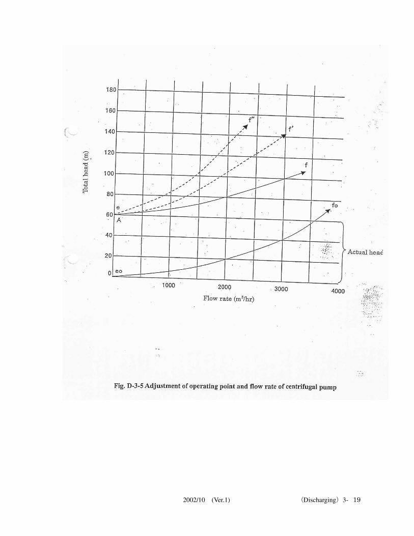
1.7.2 Operating point and flow rate adjustments of centrifugal pump The head loss of the oil delivery pipeline may be considered to increase proportionally to the square of
the flow rate.
Since the total head of the pump is the sum of the actual head and the head loss in the pipeline, if the
actual head is taken along the vertical axis (at point A), and if resistance curves e-f are plotted by
shifting the resistance curves eo-fo to the point A taken as the starting point, then these resistance
curves express the total heads of the pump due to the oil delivery pipelines corresponding to various
flow rates. If the discharge valve in the oil delivery pipeline is throttled, the resistance in the discharge valve
increases. The resistance curves e-f change to curve e-f' and further to e-f" as the valve is throttled. Thus, the operating point of the pump is the intersection of the total head curve and the resistance curve.
To change the flow rate, the total head and the resistance may be changed. The methods given below describe how to change the total head and the resistance.
1) Changing the degree of opening of valve
By changing the degree of opening of the suction and discharge valves, the head loss changes, and
as a result the flow rate and the pump efficiency changes. However, the degree of opening of the
suction valve should not be adjusted because of the risk of cavitation. Throttling the discharge
valve and operating for a long period at less than 50% of the required flow rate is also not
recommended. 2) Changing the pump rpm
Changes the total head. The pump efficiency does not change, therefore the method of adjusting
the discharge valve is a recommended method. 3) Flow rate adjustment by adjusting the bypass valve
The method of returning a part of the discharged liquid to the suction side may also be used.
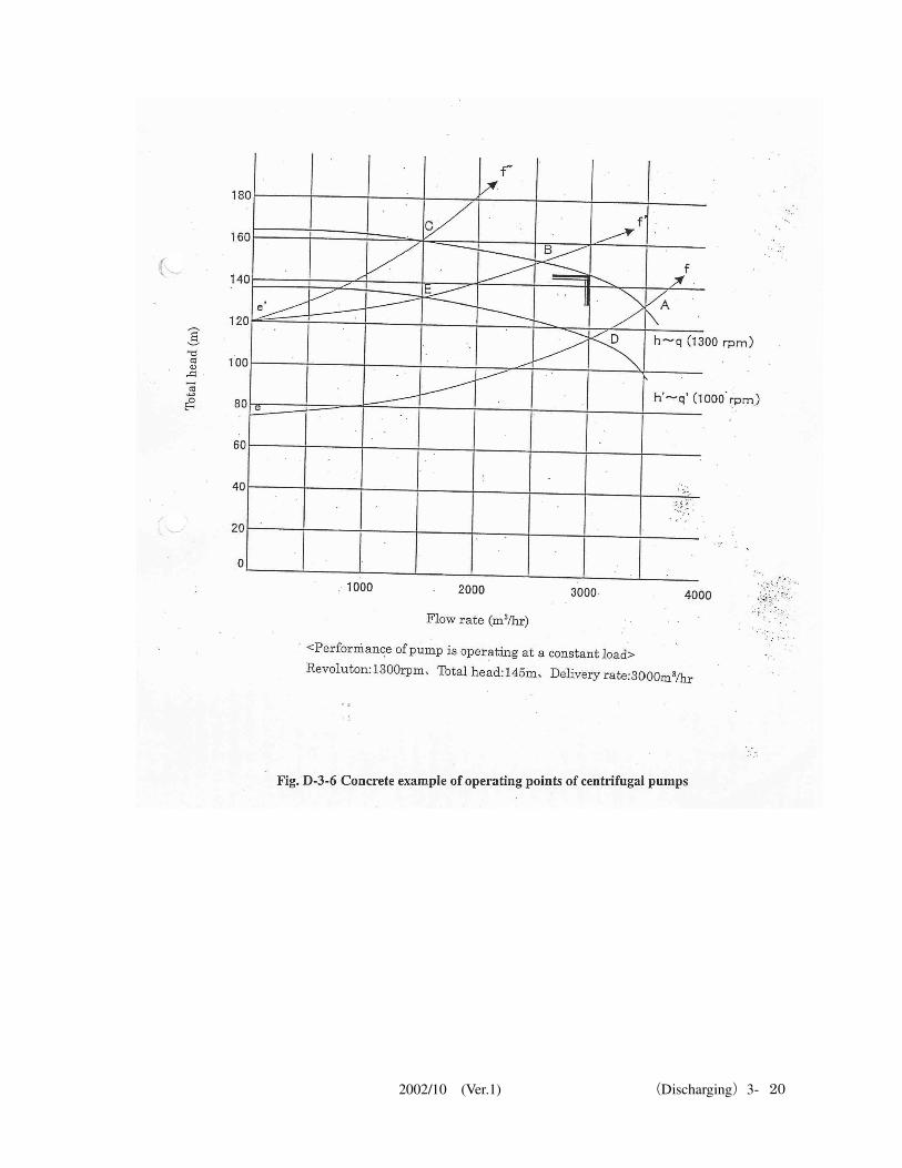
1.7.3 Concrete example of operating points of centrifugal pump
Fig. D-3-6 is used to explain the concrete example of operating points. If the actual head is taken as 75 m (point e), the resistance curve when the discharge valve is fully open
is taken as the curve e-f, and the pump is operating at the rated rpm, then the operating point of the
pump becomes point A, which is the intersection of the resistance curve e-f and the total head curve h-q.
In this case, the pump will be operating at a point not at the rated rpm. From the curve h-q, the total
head is approximately 130 m, the discharge rate is approximately 3,500 m3/h and the shaft power is
about 1,550 kW, indicating that the prime mover is overloaded. As delivery of oil to the shore tank progresses, the level in the shore tank rises and the level in the
ship's tank drops so that the actual head shifts from point e (75 m) to the point e' (120 m). Accordingly,
the resistance curve also shifts gradually from e-f to e'-f'. As a result the operating point of the pump shifts from point A to point B on the h-q curve, the total
head increases and the discharge rate decreases. If the valve in the oil delivery line is throttled when the pump is operating at point B, the resistance
curve e'-f' changes to the curve e'-f" and the operating point shifts from point B to point C. In this case,
the total head does not change appreciably but the discharge rate varies significantly. The points D and E indicate operating points when the rpm of the pump operating at points A and B
respectively is reduced and the total head curve becomes h'-q'. As mentioned above, either the pump rpm can be changed or the valve on the discharge side of the
pump can be throttled to change the operating point of the pump. Moreover, adequate care is necessary,
especially during cargo handling operations of tankers because a change in the operating point occurs
due to a shift in the resistance curve since the change in the actual head is large.
2002/10 (Ver.1) (Discharging)3- 19
2002/10 (Ver.1) (Discharging)3- 20
2002/10 (Ver.1) (Discharging)3- 21
2. Measures when discharging work is suspended
Click here to view video – 031.mp4
2.1 Pump no-load operation
Sometimes the discharging operation is suspended temporarily either for changing over the shore tank
or for some other reason. If the suspension of operation is for a short time, the cargo pump is not
stopped but the discharge valve is closed until the operation can be resumed. The no-load operation of
the pump saves time since the pump need not be stopped and re-started. It is adopted so that
discharging of cargo oil can be re-started immediately.
2.1.1 Procedure for no-load operation of pump
The procedure for no-load operation of the cargo pump is as described below.
1) Notify the Engine Department about the no-load operation of the cargo pump. 2) Station the relevant personnel in the pump room.
3) Fully close the pump discharge valve and reduce the pump rpm to the minimum rpm. 4) Fully open the suction line from the tank to the pump. 5) If discharging was being carried out by opening multiple tanks, make each set of pump/tank
independent to prevent transfer of oil due to the difference in ullage between tanks. 6) Discuss the handling of manifold gate valve with the relevant staff at the terminal.
2.1.2 Precautions during no-load operation
Take the precautions mentioned below during no-load operation of the pump.
1) Guard against overheating trip of the pump casing. During no-load operation, the pump casing temperature rises since the oil in the pump casing is not
replaced. Although the overheat tripping temperature of the pump casing is not fixed and depends
on the actual condition of the ship, it is generally about 65 °C to 75 °C.
2) Depending on the terminal, if the casing temperature rises, the oil in the pump may be returned to
tanks filled with the same grade of oil through the direct filling line or the eductor line for replacing
the oil. In such cases, there may not be restrictions on the time for the no-load operation, but if the time for
the no-load operation is expected to exceed 15 minutes, then the pump should be stopped. 3) It should be borne in mind that most troubles occur when the operation is changed over from
unconventional to normal operation.
2.2 Temporary stop of cargo pump
The cargo pump may sometimes be stopped temporarily and the discharging operation suspended for
changing over the shore reception tank.
2.2.1 Procedure for temporary stop of pump
The procedure for temporary stop of the cargo pump is described below.
1) Station the relevant crew members in the pump room. 2) Notify the Engine Department about the temporary stop of the cargo pump with a request to station
The personnel stationed in the pump room should check and report pump casing temperatures. However, in
some ships, the pump casing and bearing temperatures can be monitored in the CCR.
The manifold gate valve is generally closed
The pump casing temperature varies depending on conditions such as the season, the oil temperature and the
temperature in the pump room. Although, it cannot be stated unconditionally, there should be no problem in
performing the no-load operation for about 10 to 15 minutes.
2002/10 (Ver.1) (Discharging)3- 22
the staff in the pump room. Take measures to cope with changes in boiler loads. 3) Checks by the deck watch on manifold pressure and presence of vibrations should be reported to
the CCR. 4) Gradually decrease the discharge rate under instructions from the terminal. Never operate the pump
to reduce the discharge rate abruptly. 5) If two or more pumps are operating in parallel, adjust the rpm and the discharge valve while
maintaining a proper balance in all the pumps in operation. 6) When the rpm of all the cargo pumps approach the minimum rpm, adjust the number of tank valves
such that each pair of tank/pump is isolated so as to prevent the transfer of oil due to ullage
differences in the tanks. Achieve line segregation by making common lines independent. This measure is also to prevent
transfer of oil when level differences exist in different tanks. 7) Operate all pumps at the minimum rpm, close the discharge valves fully and stop the delivery of
oil. 8) Request the Engine Department to stop the pumps. Also notify them the time by which the pumps
are to be stopped. 9) After discussing with the terminal, close the manifold gate valve fully.
Sometimes measures to prevent the liquid-sealed condition may have to be adopted when the gate
valve is fully closed, depending on the duration of the suspension of operation. Although measures for preventing the liquid-sealed condition vary with the terminal, generally the
crossover gas intake valve and the direct filling valve are opened to prevent such a condition. (Refer to "2.4.2 Concrete example of the method for preventing liquid-sealed condition" on P3-24
of the "Discharging Section.")
2.2.2 Precautions during temporary stop of pump
Take the precautions mentioned below during the temporary stop of the cargo pump.
1) Operate the governor so as to reduce the rpm by 20 each time, similar to the procedure for raising
pump rpm, taking care to avoid abrupt load fluctuations. 2) If multiple tanks are being discharged, differences in the levels of tanks exist, and all cargo pumps
have approached close to their minimum rpm, take precautions for draft, trim and heel otherwise oil
may shift among the tanks.
2.3 Emergency stop of cargo pump
2.3.1 Conditions for emergency stop The conditions below may be considered for initiating an emergency stop.
1) When there is a risk of major damage to the Chiksan arm as a result of shifting of the ship due to
gust or gale during the discharging operation 2) When an earthquake or tsunami occurs during the discharging operation 3) When a major oil leak has occurred on the ship or at the receiving terminal
2.3.2 Harmful effects of emergency stop
The harmful effects of emergency stop of the cargo pump are as given below.
1) Small or large pressure surges occur during an emergency stop of the cargo pump Secondary damage may occur to cargo handling equipment such as lines and valves on the ship or
at the terminal due to such pressure surges. 2) The supply-demand balance of steam for the boiler collapses abruptly. The safety valve of the
boiler activates, and a large quantity of steam that was being supplied to the turbine may be
dumped. Large noise occurs as a consequence. 3) Black smoke is emitted due to the abrupt load fluctuations of the boiler.
2.3.3 Emergency stop method
The method described below is to be adopted when an emergency stop of the cargo pump is initiated
from the CCR.
2002/10 (Ver.1) (Discharging)3- 23
1) If a push button is provided, open the protective cover of the emergency stop button and press the
button. 2) If a lever is provided, open the protective cover of the emergency stop lever, pull the lever toward
you and turn it toward the emergency stop side.
2.3.4 Measures after the emergency stop
Adopt the measures given below after the emergency stop of the cargo pump.
1) Fully close the discharge valve. 2) Restore the governor to the minimum rpm position. 3) After the discharge valve is fully closed, fully open the tank suction valve. 4) After discussing with the terminal, close the gate valve if possible. To mitigate the pressure surge,
the time for closure of gate valve is taken as 60 or more seconds, whenever possible. 5) Notify the Engine Department and check for abnormalities in the turbine, pump and other parts. 6) Check the cargo handling appliances and other necessary locations on the ship and the shore
reception terminal. 7) When normal conditions are restored, perform the reset operation and make preparations to restart
the pump. Reset operation may sometimes be performed from the engine room or from the CCR. If an emergency stop lever has been provided, remove the protective cover, pull the lever toward
you, turn it to the normal position and reset.
2.4 Measures to prevent liquid-sealed condition
Click here to view video – 034.mp4
When cargo handling is suspended, the liquid remaining in the lines should be removed if necessary,
while communicating with the terminal in order to prevent oil leaks due to excessive pressure in the
line, and subsequently, measures to prevent the liquid-sealed condition should be adopted.
2.4.1 Methods for preventing the liquid-sealed condition
Methods for preventing the liquid-sealed condition are given below.
1) Method of using the gas intake valve 2) Method of using tank valve through direct filling line
Oil circulation in the ship's discharge line becomes necessary when implementing measures to
prevent liquid-sealed condition at SPM, depending on the method adopted. This work should be
performed again when re-starting the discharging operation. When the pump is stopped, measures should be taken using tank valves to prevent shift of oil
between the tanks.
2002/10 (Ver.1) (Discharging)3- 24
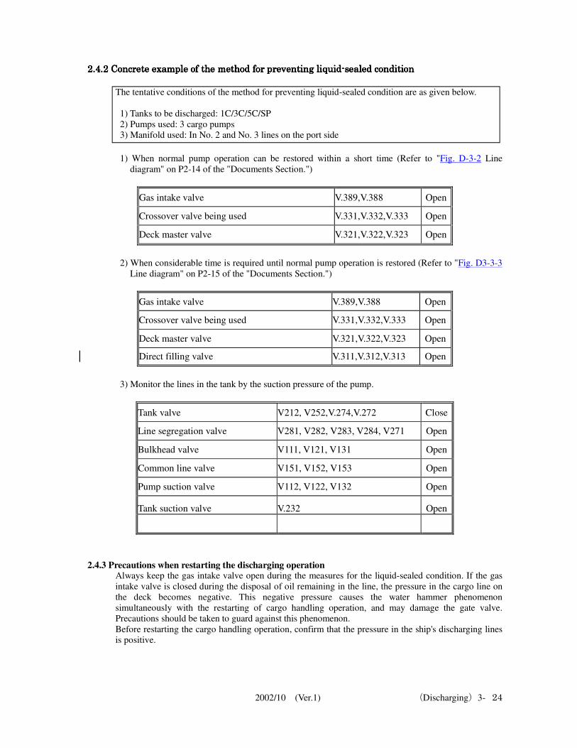
2.4.2 Concrete example of the m2.4.2 Concrete example of the m2.4.2 Concrete example of the m2.4.2 Concrete example of the method for preventing liquidethod for preventing liquidethod for preventing liquidethod for preventing liquid----sealed conditionsealed conditionsealed conditionsealed condition
The tentative conditions of the method for preventing liquid-sealed condition are as given below.
1) Tanks to be discharged: 1C/3C/5C/SP 2) Pumps used: 3 cargo pumps 3) Manifold used: In No. 2 and No. 3 lines on the port side
1) When normal pump operation can be restored within a short time (Refer to "Fig. D-3-2 Line
diagram" on P2-14 of the "Documents Section.")
Gas intake valve V.389,V.388 Open
Crossover valve being used V.331,V.332,V.333 Open
Deck master valve V.321,V.322,V.323 Open
2) When considerable time is required until normal pump operation is restored (Refer to "Fig. D3-3-3
Line diagram" on P2-15 of the "Documents Section.")
Gas intake valve V.389,V.388 Open
Crossover valve being used V.331,V.332,V.333 Open
Deck master valve V.321,V.322,V.323 Open
Direct filling valve V.311,V.312,V.313 Open
3) Monitor the lines in the tank by the suction pressure of the pump.
Tank valve V212, V252,V.274,V.272 Close
Line segregation valve V281, V282, V283, V284, V271 Open
Bulkhead valve V111, V121, V131 Open
Common line valve V151, V152, V153 Open
Pump suction valve V112, V122, V132 Open
Tank suction valve V.232 Open
2.4.3 Precautions when restarting the discharging operation
Always keep the gas intake valve open during the measures for the liquid-sealed condition. If the gas
intake valve is closed during the disposal of oil remaining in the line, the pressure in the cargo line on
the deck becomes negative. This negative pressure causes the water hammer phenomenon
simultaneously with the restarting of cargo handling operation, and may damage the gate valve.
Precautions should be taken to guard against this phenomenon. Before restarting the cargo handling operation, confirm that the pressure in the ship's discharging lines
is positive.
2002/10 (Ver.1) (Discharging)3- 25
3. Troubleshooting
3.1 Rise in tank pressure
If the tank pressure rises beyond the set value and can no longer be controlled, work that has caused
this rise should be stopped. 3.1.1 Causes
The causes mentioned below may be considered for the rise in tank pressure.
1) Rise in tank pressure due to crude oil washing 2) Rise in tank pressure due to abnormality in systems such as IGS
3.1.2 Measures to be adopted
1) When tank pressure rises due to crude oil washing If crude oil washing is performed using crude oil of high vapor pressure, the tank pressure exceeds
the predetermined pressure and rises. The tank pressure cannot be controlled, and release of gas to
the atmosphere may become unavoidable. If the tank pressure shows a rising trend (as confirmed
from IGS record sheets) and if the discharging rate is to be reduced, then the COW work should be
stopped. If the discharging rate is low and if it has to be increased a short while later, then the tank pressure
can be reduced and COW can be implemented. In this case, extreme care should be taken against
fluctuations in the tank pressure. Release of gas to the atmosphere during the discharging operation
is prohibited except in the event of an emergency when it is unavoidable. 2) When the tank pressure rises due to an abnormality in systems such as IGS
a) Sometimes the tank pressure cannot be controlled at the predetermined pressure and it rises
because of an abnormality in the IGS. In this case, the capacity of the inert gas fan exceeds the discharging capacity. The cause may be
attributed to abnormality in the control signal to the valve which to be exhaust excessive inert gas
through the funnel or abnormality in the valve itself. The tank pressure can be controlled in such a
case by manual adjustments of the relevant valve. b) Sometimes a false signal is input due to abnormal pressure signal from the pickup line of the IG
main line and a pressure greater than the actual pressure is indicated. The breather valve and the
P/V breaker do not activate upon receiving false signals since they activate only at the actual
pressure, so they do not release any gas to the atmosphere. In this case, the water level of the P/V
breaker and the correct tank pressure can be known from the pressure gauges in each tank. Thus, if
discharging is performed with care, the operation can be continued.
3.2 Drop in tank pressure
If discharging is continued without adopting any measures even though the tank pressure is dropping,
then the pressure in the tank becomes negative and a major accident such as denting of the tank occurs.
3.2.1 Causes
The drop in tank pressure may be attributed to the discharging capacity exceeding the capacity of the
inert gas fan. 3.2.2 Measures
The tank pressure can be raised by starting the standby inert gas fan and the pressure can be controlled
at the predetermined pressure. The capacity of the inert gas fan is 125% of the maximum discharging
capacity of the ship. If the standby fan cannot be used, the discharging rate should be reduced until the tank pressure can be
controlled.
* About tank pressure alarm settings
2002/10 (Ver.1) (Discharging)3- 26
Means have been provided in the IGS control panel for setting alarms for tank pressure arbitrarily.
Although tank pressure is monitored, settings should be made such that rise or drop in tank pressure
can be detected visually or audibly at an early stage. Fixed alarms are provided that issue alerts at the
low pressure level of 1.96 kPa (200 mmAq) and at the very low pressure level of 0.98 kPa (100
mmAq.) If the IGS (tank pressure) and cargo pump have been interlocked, then the cargo pump initiates an
emergency stop when the tank pressure drops below 0.98 kPa(100 mmAq).
3.3 Tripping of cargo pump
3.3.1 Causes The tripping of the cargo pump may be attributed to the causes given below.
1) Abnormality in the cargo pump If the abnormality is in the pump, only the pump trips. In addition to tripping due to abnormality in
the pump itself, the pump may trip due to wrong activation of the sensor. Also, if two or more
pumps are in operation, the so-called "defeated" phenomenon may occur. The kinds of manual and automatic trips of the pump are as given below.
a) Emergency stop from the CCR that causes the pump to trip b) Emergency stop from the pump room that causes the pump to trip c) Emergency stop from the turbine side that causes the pump to trip d) Overheating of pump casing e) Overheating of pump bearing f) High pump discharge pressure (high back pressure) g) Overheating of bulkhead stuffing box h) Overspeeding of pump rpm i) Low LO pressure in the steam turbine bearing
2) Abnormality in the boiler If an abnormality occurs due to tripping of the boiler from misfiring or other reasons, stop all the
operating pumps manually. 3) IGS trip
If the cargo pump and IGS have been linked, the protective device for preventing denting of the
tank activates and the pump stops automatically when the IG main pressure becomes 0.98 kPa
(100 mmAq).
4) Blackout In case of a power failure, all operating pumps trip and stop. This is the most important problem,
which is also unavoidable. 3.3.2 Measures
1) Fully close the discharge valve and restore the governor to the minimum rpm position. (Should be
conformed on the turbine side also) 2) If any pump is still operating, take care in the reduction of suction pressure since the discharge rate
per pump is likely to increase. Reduce the pump rpm, throttle the discharge valve or close it fully, if
necessary. 3) Maintain close contact with the Engine Department and make adjustments such as changing the
rpm (increase or decrease rpm) of the pump to match the load fluctuations of the boiler. 4) If all the pumps have tripped, make efforts to prevent the shift of oil among cargo tanks by
operating the relevant valves. Maintain the ship's attitude (draft, trim, heel, etc.) before the tripping
of the pump. 5) If tripping has occurred due to blackout, one of the hydraulic pumps can generally be operated by
the emergency generator, and valves can be remotely controlled. However, the system provided on
the ship should be confirmed. Valve operations should be performed using the emergency hand
Thus, this is a system in which low pressure alarm activates when the tank pressure is 1.96 kPa (200 mmAq),
visually and audibly notifies an abnormal condition and makes it necessary for measures to be adopted before
the pump trips
2002/10 (Ver.1) (Discharging)3- 27
pump. Although the positions of the valves at blackout are maintained, prompt measures should be
adopted. 3.3.3 Cause investigation
If a pump trips, it should not be restarted without investigating the cause of the trip.
1) The cause of tripping of the pump is not restricted to the ship alone; sometimes, error in valve
operation on the shore may cause pressure surge, and the pump may have tripped due to excessive
pressure. In such cases, thorough checks for the presence of oil leaks and checks of cargo handling
equipment such as two-way valves and lines should be carried out. 2) A pump trip may occur due to a simple cause or due to multiple causes that are interrelated in a
complex manner. Thus, simple conclusions should not be arrived at but the causes should be
investigated from various angles. It should be borne in mind that if the pump is restarted after
making simple judgments, the inherent fault may develop into a major accident.
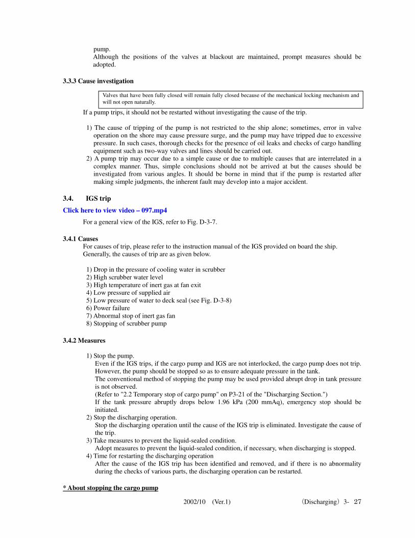
3.4. IGS trip
Click here to view video – 097.mp4
For a general view of the IGS, refer to Fig. D-3-7.
3.4.1 Causes
For causes of trip, please refer to the instruction manual of the IGS provided on board the ship. Generally, the causes of trip are as given below.
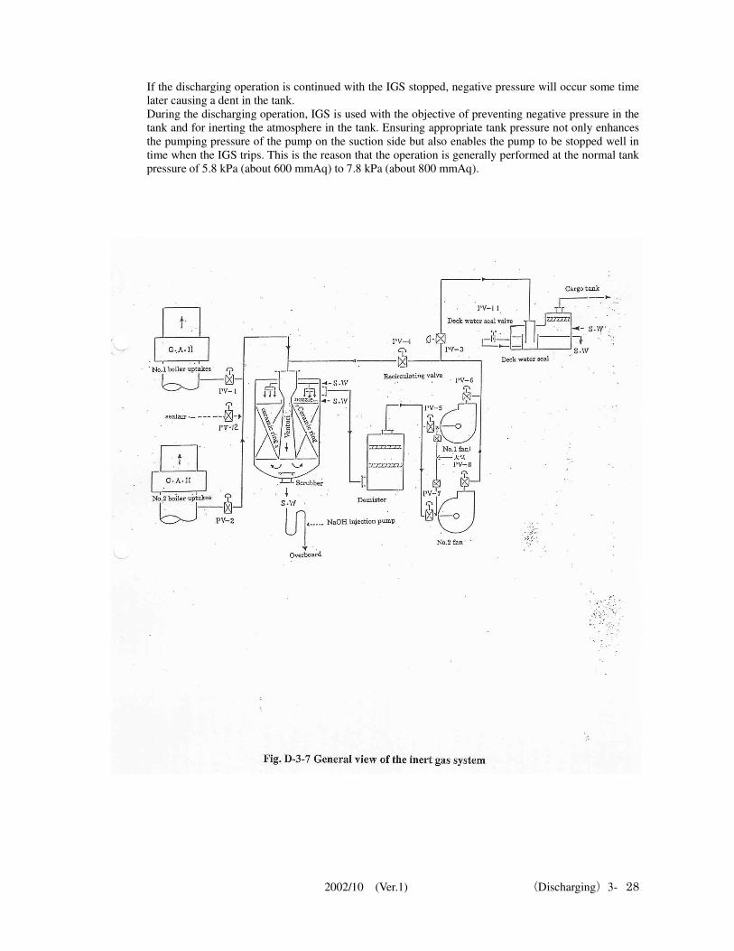
1) Drop in the pressure of cooling water in scrubber 2) High scrubber water level 3) High temperature of inert gas at fan exit 4) Low pressure of supplied air 5) Low pressure of water to deck seal (see Fig. D-3-8) 6) Power failure 7) Abnormal stop of inert gas fan 8) Stopping of scrubber pump
3.4.2 Measures
1) Stop the pump. Even if the IGS trips, if the cargo pump and IGS are not interlocked, the cargo pump does not trip.
However, the pump should be stopped so as to ensure adequate pressure in the tank. The conventional method of stopping the pump may be used provided abrupt drop in tank pressure
is not observed. (Refer to "2.2 Temporary stop of cargo pump" on P3-21 of the "Discharging Section.") If the tank pressure abruptly drops below 1.96 kPa (200 mmAq), emergency stop should be
initiated. 2) Stop the discharging operation.
Stop the discharging operation until the cause of the IGS trip is eliminated. Investigate the cause of
the trip. 3) Take measures to prevent the liquid-sealed condition.
Adopt measures to prevent the liquid-sealed condition, if necessary, when discharging is stopped. 4) Time for restarting the discharging operation
After the cause of the IGS trip has been identified and removed, and if there is no abnormality
during the checks of various parts, the discharging operation can be restarted.
* About stopping the cargo pump
Valves that have been fully closed will remain fully closed because of the mechanical locking mechanism and
will not open naturally.
2002/10 (Ver.1) (Discharging)3- 28
If the discharging operation is continued with the IGS stopped, negative pressure will occur some time
later causing a dent in the tank. During the discharging operation, IGS is used with the objective of preventing negative pressure in the
tank and for inerting the atmosphere in the tank. Ensuring appropriate tank pressure not only enhances
the pumping pressure of the pump on the suction side but also enables the pump to be stopped well in
time when the IGS trips. This is the reason that the operation is generally performed at the normal tank
pressure of 5.8 kPa (about 600 mmAq) to 7.8 kPa (about 800 mmAq).
2002/10 (Ver.1) (Discharging)3- 29
2002/10 (Ver.1) (Discharging)3- 30
3.5 Drop in the level of deck seal water
When the IGS is in operation, alarm is issued when the condition is "Low deck seal water level" or
"Drop in flow." The deck seal prevents back flow of gas from the cargo tank using liquids such as sea
water, and is called the deck water seal. Although IG isolating valve or non-return valve is installed in
the IG piping system, if these valves fail, oil leak cannot be exempted. If the deck seal is not provided,
the gas in the tank will flow back to the engine room.
3.5.1 Causes
The items mentioned below may be considered as causes for the low deck seal water level.
1) Failure of pump supplying water to the deck seal 2) Damage to the deck seal itself (hole in the seal due to corrosion of the piping supplying seal water
or corrosion of the blind flange in the drain.) 3) Closure of the water supply line
3.5.2 Measures
1) In case of failure of pump supplying water to the deck seal Two dedicated pumps are provided for supplying water to the deck seal - one dedicated pump and
one pump used for miscellaneous purposes, which is the standby pump. If the cause is in the pump,
then start the standby pump. One deck water seal pump should always be in operation except during maintenance and when the
ship is dry-docked. 2) When the cause is in the piping or in the seal water tank
Stop the IGS and the cargo pump. Also, if the seal water tank is almost empty, measures to prevent
backflow from the cargo tank, such as by closing the IG master valve should be adopted. If
measures to prevent backflow are not adopted, there is a risk of entry of inert gas or petroleum gas
into the engine room, which is a very dangerous condition. 3) If backflow prevention measures are adopted
a) At terminals where gas can be released to the atmosphere, stop the cargo pump and then
release the tank pressure by opening the vent riser. b) If gas cannot be released to the atmosphere, stop the cargo pump, then close the IG branch
valve in each tank. Subsequently, bring the pressure in the IG main line to zero by opening
the vent riser.
3.6 Rise in the concentration of oxygen in the supplied inert gases
3.6.1 Causes In most cases, the rise in the concentration of oxygen in the supplied inert gases occurs due to load
fluctuations of the boiler (reduce the rpm of the cargo pump or reduce the number of pumps being
used). Generally, the concentration of oxygen in the supplied inert gases fluctuates temporarily due to load
fluctuations of the boiler and then rises.
3.6.2 Measures
1) When the concentration of oxygen in the supplied inert gases rises due to load fluctuations of the
boiler, the concentration will drop if a constant load condition of the boiler is maintained. This
Concrete example (when ship is underway)
1) The internal surfaces of the deck seal water tank were painted, but the blind flange which was not painted,
corroded and holed within about one year. The blind flange was renewed. During inspection of the deck seal
water tank, it should be carefully noted that the usage environment is very severe due to the presence of
sulfur content, which cannot be removed by the scrubber.
2) Corrosion of the piping occurred at locations where the piping was secured using U-bands and at flat
portions of the piping that were not inclined. The pipes were removed and repaired
2002/10 (Ver.1) (Discharging)3- 31
condition is not favorable for equipment such as condensers, but if excess steam from boiler can be
dumped out,the oxygen concentration reduces and its value can be regulated at a constant level. 2) Stop the discharging operation.
Stop the discharging operation when the concentration of oxygen in the supplied inert gases rises
and if any of the conditions mentioned below is satisfied. a) Oxygen concentration in the tank exceeds 8% by volume. b) If supply is no longer possible because of failure of the inert gas system c) If the pressure within the tank has dropped below +1.961 kPa (+200 mmAq) d) If the charterer or the terminal has specified restrictions on oxygen concentration that are
stricter than the criteria given above, then those restrictions take priority.
3.7 Failure of the hydraulic valve and the hydraulic system
If the hydraulic valve or the hydraulic system fails, the valve should be operated using the emergency
hand pump. However, the actions to be taken differs depending on the type of failure that has occurred.
3.7.1 Measures against failure of solenoid valve
(If installed in the accommodation space (hydraulic pump unit room)
1) If remote operation from the CCR is not possible, press the manual operating buttons to the left and
right ends of the solenoid (open/close sides) using the tip of a screw driver and close or open as
required. However, if the abnormality is in the open side of the open-shut valve, even if it is opened, it may
be excited to initiate closing and the valve may be closed. 2) If remote operation is not possible even after performing the procedure in 1), the solenoid is likely
to be defective (open or closed side of the solenoid) and it should be renewed. There is no need to
shut off the power for removing the defective part and replacing it with a spare. Moreover, no tools
are required for the replacement, and the replacement work can be easily performed. 3) Operating the valve using the hand pump
Most of the solenoid valves in the hydraulic pump unit room are valves of the pump room.
Therefore, the hand pump can be directly connected to the valve actuator and the valve can be
opened or closed. If the solenoid valve itself has failed, the power needs to be shut off. However,
to avoid shutting off the power, the power unit of the solenoid valve can be removed and the hand
pump can be used for opening/closing the valve. Remote operation of other valves can also be
performed in this way. The connector for the hand pump is installed near the solenoid valve
chamber. Fully open or fully close the valve at the selected position while observing the flowmeter
on site. Follow the procedure given below for operating the valve using the hand pump.
a) The hand pump cannot be connected easily to the self-seal coupling since it is subjected to
pressure. Therefore, release the pressure by pressing against the connector strongly with a flat tool.
With this action, there is a possibility that hydraulic oil at high pressure may spray out. If it does,
use cotton waste to suppress the hydraulic oil. If you use the "air bleed handle provided with the
self-seal coupling," you can easily release the pressure. b) Fit the self-seal coupling after releasing the pressure. c) Set the hand pump selector lever to the "Open" or "Close" side and operate the hand pump.
(Refer to "3) To directly operate the valve in the pump room" on P3-32 of the "Discharging
Section.")
3.7.2 Measures against failure of solenoid valve (when solenoid is in the local box on the upper deck)
The measures below are to be adopted when the solenoid valve cannot be replaced and hydraulic pump
cannot be stopped since the system is working during the cargo handling operation, and moreover,
when the hydraulic stop valve of the local box cannot be closed. Under such conditions, all valves other
than the valve with the abnormality can be remotely operated from the CCR.
1) Open-shut valve
a) Remove both the closing and opening sides of the power unit of the solenoid in the open-shut
valve.
2002/10 (Ver.1) (Discharging)3- 32
b) Since hydraulic pressure is acting on one of the connectors fitted to the self-seal coupling of the
hand pump, release pressure by pressing against it strongly with a flat tool. With this action, there is a possibility that hydraulic oil at high pressure may spew out. If it does,
use cotton waste to suppress the hydraulic oil. If you use the "air bleed handle provided with the
self-seal coupling," you can easily release the pressure. c) Fit the self-seal coupling after releasing the pressure. d) Set the hand pump selector lever to the "Open" or "Close" side and operate the hand pump. e) Fully open or fully close the valve at the selected position while observing the flowmeter on
site. f) In the fully closed condition, the valve cannot open and remains closed due to the mechanical
locking mechanism. 2) Valve whose degree of opening can be adjusted
a) Set the valve position at the CCR to neutral for valve whose degree of opening can be adjusted. b) Fit the self-seal coupling. c) Set the hand pump selector lever to the "Open" or "Close" side and operate the hand pump. d) Fully open or fully close the valve at the selected position while observing the flowmeter on
site. f) In the fully closed condition, the valve cannot open due to the mechanical locking mechanism. g) If the valve remains excited even if its position is set to "Neutral," remove the power supply
unit. 3) Directly operating the valve in the pump room
a) The valve can be operated regardless of whether the hydraulic system is operating or not. b) The valve can be operated regardless of the position of the valve operating knob in the CCR. c) Close the stop valve in the hydraulic pipe connected to the actuator of the valve. d) Remove the self-seal coupling (hydraulic pipe) fitted to the valve. e) Fit the self-seal coupling of the hand pump to the relevant part. f) Set the hand pump selector lever to the "Open" or "Close" side and operate the hand pump. g)Open or close the valve fully at the selected position while observing the open/close indicator
visible from outside the valve body. 3.7.3 Measures against damage to the hydraulic piping in the tank
If the hydraulic piping in the tank is damaged, the valve cannot be operated even if the hydraulic
system is operating normally. Free the gases in the tank containing the valve and repair the hydraulic
piping. If the discharging operation is in progress, the schedule needs to be changed by switching over from the
tank main valve to the tank stripping valve for discharging the said tank. Depending on the oil
remaining in the tank, the discharging time may be delayed, but there should not be any problem in the
discharging operation itself.
1) Measures to be adopted when the damage to the hydraulic piping in the tank is minor a) Rotate the needle valve
*25 of the solenoid valve in the local box counterclockwise and increase
he flow rate of the hydraulic oil. At the normal flow rate, the valve cannot be operated because of leaks in the hydraulic line in
the tank. For this reason, the flow rate should be increased so as to compensate for the amount
lost due to leaks. b) Turn the valve operating knob in the CCR to open or close the valve. c) If the oil leak is minor, then the valve operates. d) If cargo handling operation is continued with the existing condition, the hydraulic oil may
flow continuously out of the tank, and the oil will have to be replenished in the hydraulic
pump unit room. If no further action is taken, the hydraulic pump trips due to low sump tank
oil level. 2) Measures to be adopted when the damage to the hydraulic piping in the tank is major
a) Rotate the needle valve *25
of the solenoid valve in the local box counterclockwise, increase the
flow rate of the hydraulic oil, and estimate the magnitude of the damage.
If the damage to the hydraulic piping is minor, the needle valve can be opened to a larger degree than is done usually,
even if the valve does not operate at the normal position of the needle valve. When this action is taken, the valve may
sometimes operate, so it may be worthwhile to take this action and confirm whether the valve works or not.
2002/10 (Ver.1) (Discharging)3- 33
If a large amount of hydraulic oil is leaking out and if you operate the valve from the CCR, the
sound of a large amount of hydraulic oil flowing through the needle valve can be heard. b) The valve cannot be operated if a large amount of hydraulic oil is flowing through. c) When the main suction cannot be used, discharging has to be carried out using the stripping
line. d) Rotate the needle valve of the said solenoid valve in the clockwise direction and fully close
it.Leakage of hydraulic oil can be stopped by this action. By this method, all valves other than the valve in the damaged hydraulic line can be operated
remotely in the normal manner. If the hydraulic stop valve in the local box is closed, all valves
in that local box cannot be used. e) This instance refers to damage to the hydraulic piping, and the valve cannot be operated even
by using a hand pump.
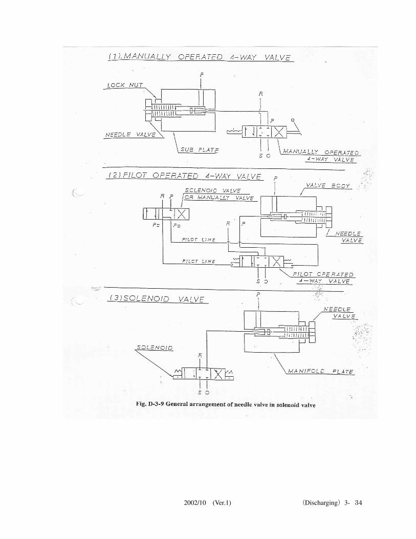
*25 What is a needle valve? (See Fig. D-3-9)
The needle valve (flow control valve) is fitted to the solenoid valve and is used for adjusting the flow
rate of hydraulic oil in the valve. If turned clockwise, the valve is throttled and the flow rate decreases; if turned counterclockwise, the
flow rate increases. Adjustments to the speed of opening/closing the valve are performed using this needle valve. The
needle valve has a lock nut, which should always be locked after performing adjustments.
2002/10 (Ver.1) (Discharging)3- 34
2002/10 (Ver.1) (Discharging)3- 35
3.7.4 Measures when the hydraulic motor of the hydraulic pump unit fails The hydraulic pump unit has two hydraulic motors of identical capacity. Normally, one motor is in
operation while the other is in the standby condition. If several valve operations are performed together,
the hydraulic pressure will drop but the standby motor operates automatically due to the backup
mechanism and maintains the designated pressure. When no backup mechanism is provided, the
standby motor should be operated manually. Even if one of the motors has failed, the other can be used for cargo handling operation.
3.7.5 Measures when the accumulator pressure drops
Sometimes the pressure of nitrogen gas charged in the accumulator *26
drops or the rubber bag in the
accumulator becomes holed and the designated pressure cannot be maintained. This abnormality can be
detected since the hydraulic pump repeatedly loads/unloads around the designated pressure even when
the valve is not operated. The nitrogen gas should be charged or the accumulator replaced after the
cargo handling operation is completed. This action is also repeated frequently when the predetermined
pressure for loading/unloading is abnormal.
*26 What is an accumulator?
An accumulator is a device that maintains the operating pressure by accumulating and releasing oil
using the compressibility of gas. The main reasons for installing the accumulator are:
1) To release the accumulated high pressure oil into the hydraulic circuit, cut down the working time
and to save energy 2) To use the accumulator to maintain pressure 3) To prevent surge pressure that occurs in the piping system
At operating pressures of 7.8 mPa (80 kg/cm2) to 8.8 mPa (90 kg/cm
2), the pressure of nitrogen
charged in the accumulator is 6.9 mPa (80 kg/cm2), and at operating pressures of 4.9 mPa (50
kg/cm2) to 5.9 mPa (60 kg/cm
2), the corresponding pressure is 3.9 mPa (40 kg/cm
2).
*27 What is an actuator?
An actuator is a device that converts the pressure energy of oil to mechanical energy, and is used in the
valve driving unit.

2002/10 (Ver.1) (Discharging)3- 36
Line Diagram Title Page
D-3-1 Free Flow Line 2-36
D-3-2 Preventing liquid-sealed condition (1/2) 2-37
D-3-3 Preventing liquid-sealed condition (2/2) 2-38
2002/10 (Ver.1) (Discharging)3- 37
2002/10 (Ver.1) (Discharging)3- 38
2002/10 (Ver.1) (Discharging)3- 39