Embed Size (px)
Citation preview
1
A 20 GW Thermal 300-metre3/sec Wave-energised, Surge-modeNutrient-pump for Removing Atmospheric Carbon dioxide,
Increasing Fish Stocks and Suppressing Hurricanes.
S H Salter
Institute for Energy Systems, School of Engineering, University of Edinburgh EH9 3JL, Scotland
AbstractAs an outcome of a workshop following Hurricane
Katrina this paper extends ideas submitted to the RoyalSociety Call for Submissions on geoengineering. Thefrequency and severity of hurricanes rise sharply if thesurface temperature of the sea exceeds 26.5 C. This isbecause of our definition of hurricane categories ratherthan having anything to do with atmospheric physics. Ifwe can pump warm water downwards to below thethermocline perhaps we can have gentle hurricanes.Designers of overtopping wave plant for energygeneration want a high product of head and flow. But thehead of water needed to overcome the density differencedue to the temperature drop with depth in many hurricanebreeding sites is often less than 200 mm. This means thatwe can use the horizontal movement of sea waves tomove water through a wall of non-return valves into anenclosure with a down-tube reaching to the thermocline.The warm water from above will mix with cold, nutrient-rich water, giving a mixture of an intermediatetemperature which will rise until is reaches the level ofthe same density, from where it will spread sideways. Ifthis layer is at 100 metres below the surface there will beenough daylight to allow the growth of phytoplankton.These are efficient carbon absorbers and the start of themarine food chain.
Keywords: Climate change, wave-energy, nutrient pump,thermocline, hurricane suppression, phytoplankton, marine foodchain.
1 Wave pumpsThere have been several proposals for using waves to
pump sea water for energy generation. Some involvewater moving over the top of a wall [1] or ramp [2], [3]into a lagoon above sea level with height optimized tomaximize the product of head and flow volume. For thehurricane-suppressing project we need a head only justlarge enough to overcome the density difference betweenthe upper and lower thermal layers.
______________________________________________© Proceedings of the 8th European Wave and Tidal EnergyConference, Uppsala, Sweden, 2009
For a salt concentration of 35,000 ppm andtemperature range from 25 C down to 10C this is only2.76 kg/m3 so that the head of water needed is very smallcompared with ocean wave heights. This means that wecan use a low freeboard enclosure with a wall of non-return valves. Most of the water will enter horizontallyrather than by over topping. A sectional view of thedesign is shown in figure 1. A vertical non-permeabletube below the valve wall will carry the water down to thethermocline. The lower part will be subject to a gentle,steady hoop tension.
2 StructureThe top of the structure seen in plan in figure 2 is a
buoyant ring formed by lashing used tyres in a hexagonalarray with buoyancy provide by foamed concrete. Tensilemembers in the form of spokes made from polypropylenerope can give it strength in the horizontal plane. Thisgives a structure which can conform to long waves andwhich has low or, because of the tyres, even a negativematerial cost.
Hanging at a depth of 17 metres below this is a secondring of tyres containing normal density concrete or bagsof gravel for negative buoyancy. The rings are joined byvertical strands of a high tensile glass/Kevlar compositearound which are Vee-shaped chlorinated rubberextrusions, shown in figure 3, which can move together toform a low drag foil section or open to make contact withthe adjacent extrusion to form a closed valve. Outside thevertical strands are horizontal hoop strands of the fullwall diameter which lie in notches in the noses of the foilsand pull the vertical strands inwards to give a doublecurvature. These horizontal hoops will resist the pressureinside the walls.
The downward water velocity is low and so the downtube can be tapered so as to increase velocity with littledrag penalty but an increase of momentum force. It canalso be tilted to direct the flow to one side. If it carries aseries of inflatable tubes it can be raised to adjust itslength, for movement in shallow water and for eventualrecovery.

2
Figure 1. A side view of the wave sink with a tapered down-tube reaching to below the thermocline in workingconfiguration and with its tapered skirt hitched up for transport in shallow water.
It will not be easy to handle a 100 metre diameter200 metre long tube of thin plastic in air but it will bepossible to edge-weld material being unwound fromsix rolls with axes slightly tilted from the verticalmounted on six rafts joined in a ring. The tube canbe lowered into the water as welding progresses andnever be separately handled.
Many wave inventors leave moorings and sea bedattachment to the end of the design process and findthat the problem is expensive and the installationslow. Wave sinks will be subject to the drag forcesof any local current and also to momentum forcesproportional to the squares of incident and reflectedwaves. Furthermore the structure has no strong pointsto which mooring cables can be connected and wemay need to operate in very deep water.
Many ocean currents take the form of largevortices known as gyres. One solution to the mooringproblem is not to moor at all. We let the units driftfreely but we bias the exit flow to one side so thatthere is a force tending to move them towards thecentre of whichever gyre is to be cooled or enriched.By adjusting the proportion of side flows we cankeep them moving round the gyre at any chosenradius from its centre. This looks quite easy in themany gyres of the Caribbean and the two alternatingcurrents along the hurricane-breeding track fromWest Africa. The Coriolis effect means that there willbe a change in the direction of a current withchanging depth so the trail of nutrients will divergefrom the path of the sink and give good dispersion.

3
Figure 2. A plan view of the more rigid part of the structure made by lashing rings of used tyres in four layers.
Figure 3. The valve wall uses 17 metre long rubber extrusions clipped to a grid of vertical and hoop wires.

4
3 Pumping rate
In a deep water wave the particles move in circularorbits with diameters which decay with depth, but therate of decay is less for longer wave periods. If weintegrate the displacements from the surface down tothe bottom of the valve wall, multiply by the wavefrequency and ignore any effect of standing wavesgenerated by the non-permeable tube below the valvewall, we can estimate water transfer as a function ofwall depth for any period.
Figure 4 Plots flow in cubic metres per second, permetre width of valve wall, per metre amplitude of theincident wave for periods of 6 to 10 seconds as afunction of the wall depth.
Figure 4. Flow coefficient as a function of wall depth.
This shows that the effect of rapid orbital decay ofshort waves balances the slower occurrence of longwaves at wall depths of about 17 metres, giving a flowof about 2.6 cubic metres a second per metre width andmetre amplitude for most of the useful wave periods. Ifwe take the annual wave climate scatter-diagram forLanzarote, typical of many trade-wind sites, reducewave amplitudes by 0.15 metres for the thermal headand 0.03 metres for loss through a non-return valve, wefind that a 100 metre diameter valve wall will transfer amean annual flow of about 150 m3/second. If wemultiply this flow rate by the specific heat of sea waterand a temperature difference of 15K we get a meantransfer rate of thermal energy of 9.6 GW.
However we can argue that this analysis isconservative because water that enters the enclosurewill form the crest of a wave that travels across itsdiameter until it reaches a closed valve-wall at theopposite side. It will then be reflected and the trough ofthe resulting anti-node will draw more water into theenclosure. The process will be repeated after anotherdiameter of travel.
If there are no spilling or plunging breakers thetransfer of energy by deep water waves to the next partof the sea is extremely efficient. One certain way ofmaking a very efficient wave energy device is to let thewater move in same way as it does when driving thenext bit of sea with the correct pressures anddisplacements at each point through the depth but alsoto prevent the generation of any further waves. For thisto happen the water should be driving a purely resistiveload with a force in proportion to velocity and with noreactive components.
Most practical wave converters must have theinevitable mechanical inertia of the material of theirdisplacing elements and also some added hydrodynamicinertia if the displacement of the water around themdiffers from that of an undisturbed wave. The skill ofthe wave energy designer should be aimed atminimizing total inertia, canceling the remaining inertiaat the most useful frequency with a spring term and thenproviding the correct resistive damping for small andmoderate wave heights and periods.
The wall of rectifying valves will present the perfectloading and displacement for half the time but will actas a reflector for the other half of the cycle. It willbehave like an electrical transmission cable with thecorrect matching resistor in series with an ideal diode.This suggests that the conversion of wave energy topumping energy ought to be nearly 100% for half thetime and zero for the other half, an average of 50% lessany flow losses caused by pressure drop through valvesor leakage from imperfect closure.
When we calculate power from flow and pressurefor the valve-wall system described above, theefficiency is only 10%, leaving considerable room forimprovement and a question about where the rest of theenergy has gone.
A second approach is to suppose that, because forhalf the time we have the ideal mechanism and for halfthe time a bad one, the incoming energy will splitequally between transmitted and reflected waves. Asenergy depends on the square of amplitude, thesuccessive internal reflections and transmissions shouldhave amplitudes which are 1/√2 of the previous wave.This series converges on the value 3.414.
The project needs numerical modeling of internalreflection and tank tests but perhaps we may hope for aflow increase of 2 to 2.5, giving flow rates of 300 to375 m3/sec and a thermal transfer of over 20 GW fromeach 100m unit in a gentle wave climate such asLanzarote. The larger waves found at higher latitudesmight double this.
The valves will open to prevent any inward force.Outward forces will be resisted by the hoop wires andradial ties. It may be possible to design valves whichopen to relieve unwanted excessive internal pressure.
0 10 20 30 40 500
1
2
3
4
5
Rectifying wall depth
m3
perm
wid
than
dm
ampl
itidu
de
5
4 Biological effects
Moving warm water down provides a large but onlytemporary thermal store. This may be useful for savingNew York from the next Katrina but there is a secondbenefit. Water at the surface will be in carbon dioxideequilibrium with the present-day atmosphere but mixingwith water below the thermocline is normally veryslow. The deep water has pre-industrial CO2 level. Thesolubility of CO2 rises with falling temperature andhigher pressure so the second effect of the system willbe the transfer of some CO2 from the atmosphere todeeper parts of the ocean.
We can influence the amount of mixing by choosingthe shape of the bottom tube. A nicely shaped returncurve and an outer sleeve will allow warm water to stayclose to the down-tube and perhaps rise back to thesurface. However vertical slits will give thin planar jetswith a large area to mix with the outside water. Byfilling or emptying water tubes in the slit edges we canchange the exit slit geometry and so adjust the mixingratio.
Numerical models support a conjecture, due toMyhrvold [4], that warm surface water mixed with coldbut nutrient-rich thermocline water will rise to the levelat which it finds water of its own density and thenspread sideways as a ‘density stratum’. Caldeira [5]points out that if the mix is controlled so that theequilibrium point is 100 metres below the surface therewill be enough light for the growth of phytoplankton.The biological food chain is a powerful way to movecarbon dioxide from the atmosphere to the sea bedwithout increasing acidity, Behrenfeld et al [6].
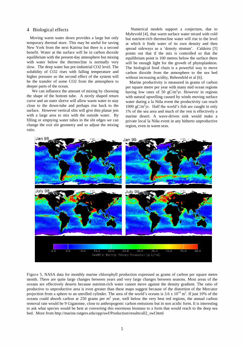
Marine productivity is measured in grams of carbonper square metre per year with many mid ocean regionshaving low rates of 50 gC/m2yr. However in regionswith natural upwelling caused by winds moving surfacewater during a la Niña event the productivity can reach1000 gC/m2yr. Half the world’s fish are caught in only1% of the sea area and much of the rest is effectively amarine desert. A wave-driven sink would make aprivate local la Niña event in any hitherto unproductiveregion, even in warm seas.
Figure 5. NASA data for monthly marine chlorophyll production expressed as grams of carbon per square metremonth. There are quite large changes between years and very large changes between seasons. Most areas of theoceans are effectively deserts because nutrient-rich water cannot move against the density gradient. The ratio ofproductive to unproductive area is even greater than these maps suggest because of the distortion of the Mercatorprojection from a sphere to an unrolled cylinder. The area of the world’s oceans is 3.6 x 10¹⁴ m2. If just 10% of theoceans could absorb carbon at 250 grams per m2 year, well below the very best red regions, the annual carbonremoval rate would be 9 Gigatonne, close to anthropogenic carbon emissions but in non acidic form. It is interestingto ask what species would be best at converting this enormous biomass to a form that would reach to the deep seabed. More from http://marine.rutgers.edu/opp/swf/Production/results/all2_swf.html

6
A steady input of all the natural nutrients all the yearround at the right level might be better than intermittentshort surges such as those that occur when fertilizersbrought down the Mississippi to the Gulf of Mexicoproducing excessive growth leading to an oxygenshortage.
Provisional estimates for direct carbon removal arebetween 104 and 105 tonnes per year from each sink,with a corresponding increase in world fish protein,Caldeira and Wood [7].
The resulting fish production is itself a usefulmechanism for carbon removal. Wilson et al [8] writethat fish drink sea water continuously and raise itsalkalinity to the range pH 8.5 to 9.2. This precipitatescalcium and some magnesium as insoluble carbonates.Small fish in warm water are proportionally moreproductive per unit of body mass. Wilson et al.suggested that the present removal rate is in the range40 to 110 x 106 tonnes of carbon a year. In a subsequenton-line addendum [9] they increase this to 900 x 106
tonnes a year with a suggestion that even this might beconservative. It would be interesting to know if wavesinks could increase the productive fraction of theoceans from 1% to say 20%.
5 Conclusions
Although the initial ideas behind this paper arosefrom a requirement to reduce the frequency and severityof hurricanes it may turn out that wave-driven down-welling may have substantial beneficial effects withregard to CO2 removal and fish production.
Entry of water horizontally through the valve-walloffers the ideal impedance-match for wave energytransfer to a low head enclosure for half the time butwill reflect energy for the other half.
This flow pattern must be distinguished fromovertopping into the much higher heads needed forpower generation.
The thermal energy transferred to the thermocline isfar larger than the incident wave energy, even if weignore the possible extra flow caused by secondaryinternal reflections.
Mooring problems can be avoided if the units canvary the side to which water is discharged so as to varytheir distance from the centre of an ocean gyre.
It may be possible to provide permanent, private laNiña events anywhere in the many large unproductiveregions of the oceans and so increase world fishproduction by an order of magnitude.
The project needs help from marine biologists toadvise about which species can be most effective forconversion of the absorbed carbon dioxide.
AcknowledgementsWork on the development of the ideas in this paper isfunded by Intellectual Ventures
References
[1] E. Mehlum. Tapchan. In Hydrodynamics OceanWave-Energy Utilization. Evans DV and FalcaoA.F. eds. Springer-Verlag, Berlin, pp. 51–55, 1986.
[2] A. N. Walton-Bott. Power plus proteins from thesea. J. Royal Society of Arts. vol 123,pp 486-503, 1975.
[3] J. P.Kofoed and A. Nielsen. The Wave Dragon–evaluation of a wave energy converter. fromhttp://people.civil.aau.dk/~i5jpk/, 1997.
[4] N. Myhrvold. Personal communication. 2008
[5] K. Caldeira. Personal communication. 2008
[6] M. J. Behrenfeld, R.O’Malley, D.A. Seigel,C. R. McClain, J. L. Sarmiento, G. C. Feldman,P. G. Milligan, R. M. Letelier, and E. S. Boss.Climate-driven trend in contemporary oceanproductivity. Nature, vol. 444, pp 752-753, 2006.
[7] K. Caldeira K and L. Wood. Personalcommunication, 2008.
[8] R. W. Wilson, F. J. Millero, J. R. Taylor,P. J. Walsh, V. Christensen, S. Jennings andM. Grosell. Contribution of fish to the marineinorganic carbon cycle. Science, vol 323pp 359-361,2009
[9] Wilson RW,et al. addendum to above.www.sciencemag.org/cgi/data/323/5912/359/DC1/12009.