Embed Size (px)
Citation preview
c o n t e n t s
2 commentary: It’s not easy Being Green 3 the Production of Steels applying 100% DrI for nitrogen removal
9 massive Savings in co2 Generation by Use of HBI
12 newS & VIewS: Jindal Steel & Power Limited announces new coal Gasification mIDreX® Plant in India
13 midrex opens UK office
www.midrex.com
3 r d / 4 t h q u a r t e r 2 0 0 9
commentary
It’s not easy Being Green
2 taBle of contents
By Christopher RavenscroftMarketing Manager
DIrect From mIDreX Page 2 thiRd/fouRth quARtER 2009
< >
In 1970, a year after the first MIDREX® Plant
started up in Portland Oregon, songwriter
Joe Raposo penned a timeless tune sung
by a children’s favorite who crooned simply
that “it’s not easy being green.” How
true that sentiment is on many levels, and
more still today. Regarding the environment,
the difficulty of being green is no excuse for
avoiding the issue.
In December world leaders met in
Copenhagen for the United Nations Climate
Change Conference (COP 15). Their goal was
for “a comprehensive, ambitious and fair
international climate change deal” to be
agreed upon by world leaders in attendance.
How much progress they make remains to
be seen; however, it is clear that the global
movement is here on a grand scale and the
steel industry must continue to be proactive
by minimizing its environmental impact.
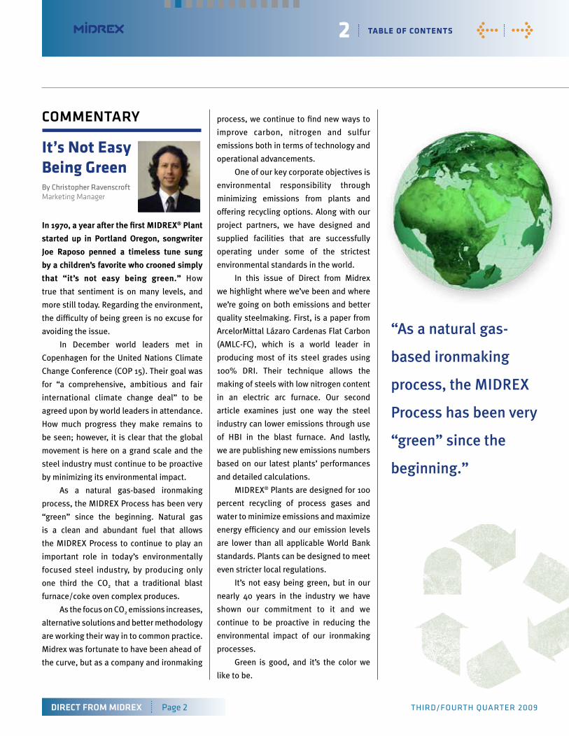
As a natural gas-based ironmaking
process, the MIDREX Process has been very
“green” since the beginning. Natural gas
is a clean and abundant fuel that allows
the MIDREX Process to continue to play an
important role in today’s environmentally
focused steel industry, by producing only
one third the CO2 that a traditional blast
furnace/coke oven complex produces.
As the focus on CO2 emissions increases,
alternative solutions and better methodology
are working their way in to common practice.
Midrex was fortunate to have been ahead of
the curve, but as a company and ironmaking
process, we continue to find new ways to
improve carbon, nitrogen and sulfur
emissions both in terms of technology and
operational advancements.
One of our key corporate objectives is
environmental responsibility through
minimizing emissions from plants and
offering recycling options. Along with our
project partners, we have designed and
supplied facilities that are successfully
operating under some of the strictest
environmental standards in the world.
In this issue of Direct from Midrex
we highlight where we’ve been and where
we’re going on both emissions and better
quality steelmaking. First, is a paper from
ArcelorMittal Lázaro Cardenas Flat Carbon
(AMLC-FC), which is a world leader in
producing most of its steel grades using
100% DRI. Their technique allows the
making of steels with low nitrogen content
in an electric arc furnace. Our second
article examines just one way the steel
industry can lower emissions through use
of HBI in the blast furnace. And lastly,
we are publishing new emissions numbers
based on our latest plants’ performances
and detailed calculations.
MIDREX® Plants are designed for 100
percent recycling of process gases and
water to minimize emissions and maximize
energy efficiency and our emission levels
are lower than all applicable World Bank
standards. Plants can be designed to meet
even stricter local regulations.
It’s not easy being green, but in our
nearly 40 years in the industry we have
shown our commitment to it and we
continue to be proactive in reducing the
environmental impact of our ironmaking
processes.
Green is good, and it’s the color we
like to be.
“As a natural gas-
based ironmaking
process, the MIDREX
Process has been very
“green” since the
beginning.”
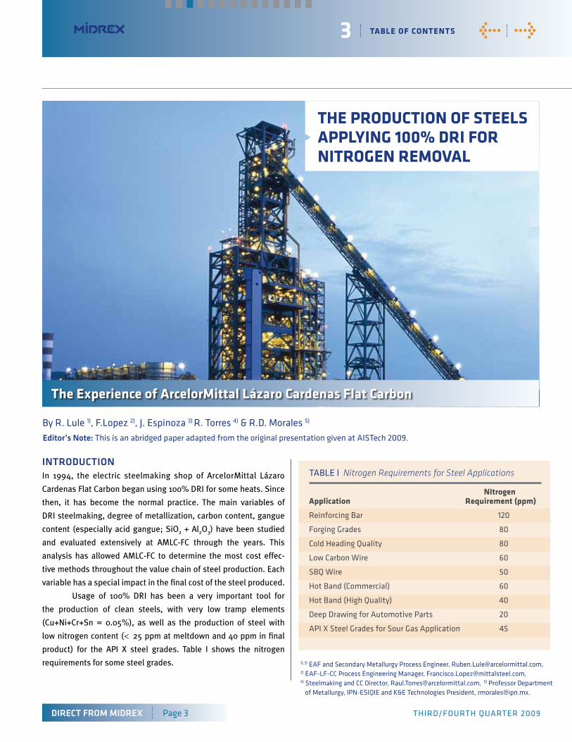
IntroDUctIon In 1994, the electric steelmaking shop of ArcelorMittal Lázaro
Cardenas Flat Carbon began using 100% DRI for some heats. Since
then, it has become the normal practice. The main variables of
DRI steelmaking, degree of metallization, carbon content, gangue
content (especially acid gangue; SiO2 + Al2O3) have been studied
and evaluated extensively at AMLC-FC through the years. This
analysis has allowed AMLC-FC to determine the most cost effec-
tive methods throughout the value chain of steel production. Each
variable has a special impact in the final cost of the steel produced.
Usage of 100% DRI has been a very important tool for
the production of clean steels, with very low tramp elements
(Cu+Ni+Cr+Sn = 0.05%), as well as the production of steel with
low nitrogen content (< 25 ppm at meltdown and 40 ppm in final
product) for the API X steel grades. Table I shows the nitrogen
requirements for some steel grades.
3 taBle of contents
application requirement (ppm)
Reinforcing Bar
forging Grades
Cold heading quality
Low Carbon Wire
SBq Wire
hot Band (Commercial)
hot Band (high quality)
deep drawing for Automotive Parts
APi X Steel Grades for Sour Gas Application
120
80
80
60
50
60
40
20
45
tABLE i Nitrogen Requirements for Steel Applications
By R. Lule 1), f.Lopez 2), J. Espinoza 3) R. torres 4) & R.d. Morales 5)
1),3) EAf and Secondary Metallurgy Process Engineer, [email protected], 2) EAf-Lf-CC Process Engineering Manager, [email protected], 4) Steelmaking and CC director, [email protected], 5) Professor department of Metallurgy, iPN-ESiqiE and K&E technologies President, [email protected].
DIrect From mIDreX Page 3 thiRd/fouRth quARtER 2009
< >
the ProductIon of steels aPPlYInG 100% drI for nItroGen reMoVal
the experience of arcelorMittal lázaro cardenas flat carbon
nItrogen
editor’s note: this is an abridged paper adapted from the original presentation given at AiStech 2009.
Nitrogen control of steel grades produced in BOFs and in EAFs
has been extensively studied, establishing a better understanding
of the metallurgical basis. Table II indicates typical levels of
nitrogen content, according to steelmaking method. In recent
recent years, high carbon levels in DRI have been studied as a
means of to CO evolution to remove nitrogen from the steel.
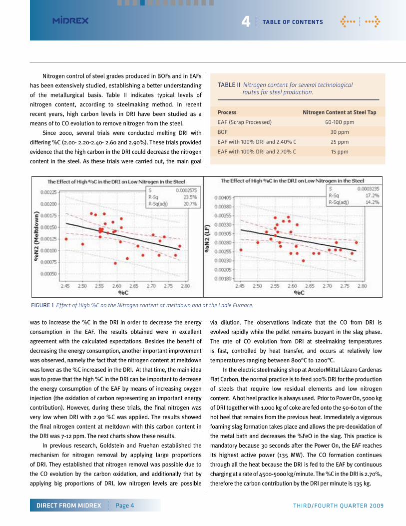
Since 2000, several trials were conducted melting DRI with
differing %C (2.00- 2.20-2.40- 2.60 and 2.90%). These trials provided
evidence that the high carbon in the DRI could decrease the nitrogen
content in the steel. As these trials were carried out, the main goal
was to increase the %C in the DRI in order to decrease the energy
consumption in the EAF. The results obtained were in excellent
agreement with the calculated expectations. Besides the benefit of
decreasing the energy consumption, another important improvement
was observed, namely the fact that the nitrogen content at meltdown
was lower as the %C increased in the DRI. At that time, the main idea
was to prove that the high %C in the DRI can be important to decrease
the energy consumption of the EAF by means of increasing oxygen
injection (the oxidation of carbon representing an important energy
contribution). However, during these trials, the final nitrogen was
very low when DRI with 2.90 %C was applied. The results showed
the final nitrogen content at meltdown with this carbon content in
the DRI was 7-12 ppm. The next charts show these results.
In previous research, Goldstein and Fruehan established the
mechanism for nitrogen removal by applying large proportions
of DRI. They established that nitrogen removal was possible due to
the CO evolution by the carbon oxidation, and additionally that by
applying big proportions of DRI, low nitrogen levels are possible
via dilution. The observations indicate that the CO from DRI is
evolved rapidly while the pellet remains buoyant in the slag phase.
The rate of CO evolution from DRI at steelmaking temperatures
is fast, controlled by heat transfer, and occurs at relatively low
temperatures ranging between 800°C to 1200°C.
In the electric steelmaking shop at ArcelorMittal Lázaro Cardenas
Flat Carbon, the normal practice is to feed 100% DRI for the production
of steels that require low residual elements and low nitrogen
content. A hot heel practice is always used. Prior to Power On, 5000 kg
of DRI together with 1,000 kg of coke are fed onto the 50-60 ton of the
hot heel that remains from the previous heat. Immediately a vigorous
foaming slag formation takes place and allows the pre-deoxidation of
the metal bath and decreases the %FeO in the slag. This practice is
mandatory because 30 seconds after the Power On, the EAF reaches
its highest active power (135 MW). The CO formation continues
through all the heat because the DRI is fed to the EAF by continuous
charging at a rate of 4500-5000 kg/minute. The %C in the DRI is 2.70%,
therefore the carbon contribution by the DRI per minute is 135 kg.
4 taBle of contents
DIrect From mIDreX Page 4 thiRd/fouRth quARtER 2009
< >
fiGuRE 1 Effect of High %C on the Nitrogen content at meltdown and at the Ladle Furnace.
Process nitrogen content at steel tap
EAf (Scrap Processed)
Bof
EAf with 100% dRi and 2.40% C
EAf with 100% dRi and 2.70% C
60-100 ppm
30 ppm
25 ppm
15 ppm
tABLE ii Nitrogen content for several technological routes for steel production.
5 taBle of contents
DIrect From mIDreX Page 5 thiRd/fouRth quARtER 2009
< >
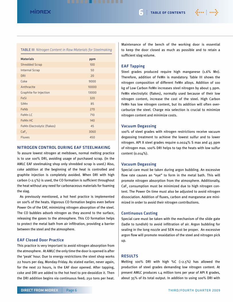
With this technology, there are several reactions responsible for
the CO formation through the heat. They were explained by R.
Morales in a previous document.
The first reaction takes place at the slag-metal interface
during the addition of DRI and coke onto the hot heel in order to
carry out the metal bath pre-deoxidation.
c + (feo) = co + fe (1)
When the oxygen injection begins, there is a direct reaction
between the gaseous oxygen and the carbon in the metal bath,
taking place at the gas-metal interface.
c + 1/2 o2 = co (2)
The decarburization of the metallic charge promotes FeO forma-
tion. Lowering carbon level in the bath raises oxygen levels and
vice versa. The next reaction is generated by the reduction of iron
oxide by the carbon in the slag at the carbon-slag interface.
(feo) + c = fe + co (3)
And, there are two reactions which consume CO. The first is
reduction of iron oxide at the surface of a CO bubble, shown as
Reaction (4). This can be controlled by an intermediate reaction
which is shown as Reaction (5). Reactions (4) and (5) occur at the
slag-gas and carbon-gas interfaces, respectively.
(feo) + co = fe + co2 (4)
co2 + c = 2co (5)
fiGuRE 3 Schematic representation of the chemical reactions that take place during slag foaming practice in the EAF. (Numbers in the figure refer to the chemical reactions described in the text.)
All of the reactions promoting CO formation are important.
They help avoid nitrogen pick up form the air. By means of
continuous slag flushing, the dissolved gases collected in the
slag are removed. DRI containing high carbon is the key to
maintenance of proper slag foaming by means of CO evolution
thoughout the heat.
nItroGen content In tHe eaF raw materIaLSIn steels produced in an EAF, nitrogen comes from two main sources:
• From the scrap (mainly from purchased scraps)
• By air infiltration into the EAF
To assure low nitrogen content of the steel and to avoid sudden
changes in nitrogen from the raw materials, all raw material inputs
to steelmaking were sampled and analyzed. Results of these
analyses are shown in Table III. (following page)
Based upon this analysis, care is taken to minimize addition
of any materials that might represent an important nitrogen
contribution.
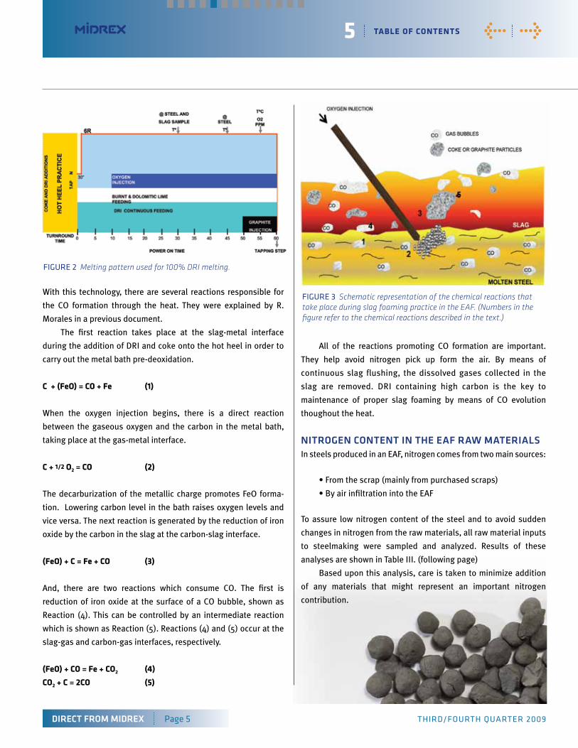
fiGuRE 2 Melting pattern used for 100% DRI melting.
6 taBle of contents
DIrect From mIDreX Page 6 thiRd/fouRth quARtER 2009
< >
nItroGen controL DUrInG eaF SteeLmaKInGTo assure lowest nitrogen at meltdown, normal melting practice
is to use 100% DRI, avoiding usage of purchased scrap. (In the
AMLC EAF steelmaking shop only shredded scrap is used.) Also,
coke addition at the beginning of the heat is controlled and
graphite injection is completely avoided. When DRI with high
carbon (>2.5%) is used, the CO formation is sufficient throughout
the heat without any need for carbonaceous materials for foaming
the slag.
As previously mentioned, a hot heel practice is implemented
on 100% of the heats. Vigorous CO formation begins even before
Power On of the EAF, minimizing nitrogen absorption of the steel.
The CO bubbles adsorb nitrogen as they ascend to the surface,
releasing the gases to the atmosphere. This CO formation helps
to protect the metal bath from air infiltration, providing a barrier
between the steel and the atmosphere.
eaF closed Door PracticeThis practice is very important to avoid nitrogen absorption from
the atmosphere. At AMLC the only time the door is opened is after
the ‘peak’ hour. Due to energy restrictions the steel shop works
22 hours per day, Monday-Friday. As stated earlier, never again,
for the next 22 hours, is the EAF door opened. After tapping,
coke and DRI are added to the hot heel to pre-deoxidize it. Then
the DRI addition begins via continuous feed; 250 tons per heat.
Maintenance of the bench of the working door is essential
to keep the door closed as much as possible and to retain a
sufficient slag volume.
eaF tappingSteel grades produced require high manganese (1.6% Mn).
Therefore, addition of FeMn is mandatory. Table III shows the
nitrogen composition of different FeMn alloys. Addition of 100
kg of Low Carbon FeMn increases steel nitrogen by about 5 ppm.
FeMn electrolytic (flakes), normally used because of their low
nitrogen content, increase the cost of the steel. High Carbon
FeMn has low nitrogen content, but its addition will often over-
carburize the steel. Charge mix selection is crucial to minimize
nitrogen content and minimize costs.
Vacuum Degassing100% of steel grades with nitrogen restrictions receive vacuum
degassing treatment to achieve the lowest sulfur and to lower
nitrogen. API X steel grades require 0.0024% S max and 45 ppm
of nitrogen max. 100% DRI helps to tap the heats with low sulfur
content (0.014%).
Vacuum DegassingSpecial care must be taken during argon bubbling. An excessive
flow rate causes an “eye” to form in the metal bath. This will
promote nitrogen absorption from the atmosphere. Additionally,
CaF2 consumption must be minimized due to high nitrogen con-
tent. The Power On time must also be adjusted to avoid nitrogen
dissociation. Addition of fluxes, carbon and manganese are mini-
mized in order to avoid their nitrogen contributions.
continuous castingSpecial care must be taken with the mechanism of the slide gate
(ladle to tundish) to avoid infiltration of air. Argon bubbling for
sealing in the long nozzle and SEN must be proper. An excessive
argon flow will promote reoxidation of the steel and nitrogen pick
up.
reSULtSMelting 100% DRI with high %C (>2.5%) has allowed the
production of steel grades demanding low nitrogen content. At
present AMLC produces 1.4 million tons per year of API X grades,
about 35% of its total output. In addition to using 100% DRI with
Materials ppm
Shredded Scrap
internal Scrap
dRi
Coke
Anthracite
Graphite for injection
feSi
SiMn
feNb
feMn LC
feMn hC
feMn Electrolytic (flakes)
Caf2
fluxes
100
50
20
9000
10000
13000
320
85
270
710
140
45
3060
450
tABLE iii Nitrogen Content in Raw Materials for Steelmaking
7 taBle of contents
DIrect From mIDreX Page 7 thiRd/fouRth quARtER 2009
< >
high carbon, raw material selection is very important to assure low
nitrogen content.
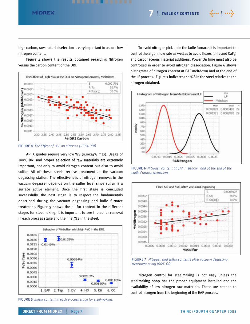
Figure 4 shows the results obtained regarding Nitrogen
versus the carbon content of the DRI.
API X grades require very low %S (0.0024% max). Usage of
100% DRI and proper selection of raw materials are extremely
important, not only to avoid nitrogen content but also to avoid
sulfur. All of these steels receive treatment at the vacuum
degassing station. The effectiveness of nitrogen removal in the
vacuum degasser depends on the sulfur level since sulfur is a
surface active element. Once the first stage is concluded
successfully, the next stage is to respect the fundamentals
described during the vacuum degassing and ladle furnace
treatment. Figure 5 shows the sulfur content in the different
stages for steelmaking. It is important to see the sulfur removal
in each process stage and the final %S in the steel.
To avoid nitrogen pick up in the ladle furnace, it is important to
control the argon flow rate as well as to avoid fluxes (lime and CaF2 )
and carbonaceous material additions. Power On time must also be
controlled in order to avoid nitrogen dissociation. Figure 6 shows
histograms of nitrogen content at EAF meltdown and at the end of
the LF process. Figure 7 indicates the %S in the steel relative to the
nitrogen obtained.
Nitrogen control for steelmaking is not easy unless the
steelmaking shop has the proper equipment installed and the
availability of low nitrogen raw materials. These are needed to
control nitrogen from the beginning of the EAF process.
fiGuRE 4 The Effect of %C on nitrogen (100% DRI)
fiGuRE 5 Sulfur content in each process stage for steelmaking.
fiGuRE 6 Nitrogen content at EAF meltdown and at the end of the Ladle Furnace treatment
fiGuRE 7 Nitrogen and sulfur contents after vacuum degassingtreatment using 100% DRI
8 taBle of contents
DIrect From mIDreX Page 8 thiRd/fouRth quARtER 2009
< >
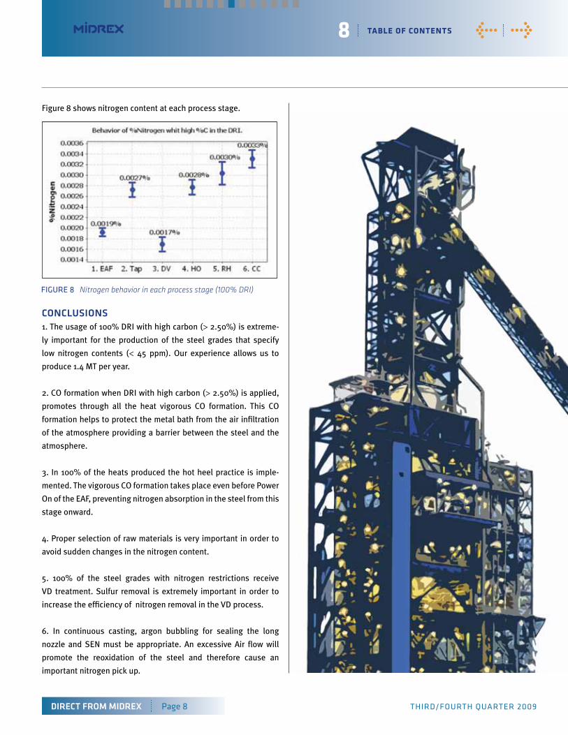
Figure 8 shows nitrogen content at each process stage.
concLUSIonS1. The usage of 100% DRI with high carbon (> 2.50%) is extreme-
ly important for the production of the steel grades that specify
low nitrogen contents (< 45 ppm). Our experience allows us to
produce 1.4 MT per year.
2. CO formation when DRI with high carbon (> 2.50%) is applied,
promotes through all the heat vigorous CO formation. This CO
formation helps to protect the metal bath from the air infiltration
of the atmosphere providing a barrier between the steel and the
atmosphere.
3. In 100% of the heats produced the hot heel practice is imple-
mented. The vigorous CO formation takes place even before Power
On of the EAF, preventing nitrogen absorption in the steel from this
stage onward.
4. Proper selection of raw materials is very important in order to
avoid sudden changes in the nitrogen content.
5. 100% of the steel grades with nitrogen restrictions receive
VD treatment. Sulfur removal is extremely important in order to
increase the efficiency of nitrogen removal in the VD process.
6. In continuous casting, argon bubbling for sealing the long
nozzle and SEN must be appropriate. An excessive Air flow will
promote the reoxidation of the steel and therefore cause an
important nitrogen pick up.
fiGuRE 8 Nitrogen behavior in each process stage (100% DRI)
Massive savings in co2 Generation by use of hBI
9
By Robert hunter, Product Application ManagerMidrex technologies, inc.
< >
Carbon emissions are a growing issue on a global scale. Modern
society has advanced through industrialization and that has led
to better standards of living and prosperity worldwide but also
contributed to increased emissions. As greater focus on CO2
becomes more mainstream, alternative solutions and better
methodology are working their way into common practice. The
industrial world contributes in a significant way to CO2 emissions
and ironmaking, like agriculture and transportation, is a major
culprit, but there is also room for improvement. This paper
examines just one way the steel industry can lower carbon
emissions through use of HBI.
IronmaKInGFrom the dawn of the Iron Age, over 3,000 years ago until the
early-1700’s, all iron was made using charcoal as the reductant.
Then, around 1710, Abraham Darby built the first blast furnace to
be fueled by coke. Darby’s development was revolutionary and it
was one of the founding events of the Industrial Revolution. It was
essential to provide the enormous quantity of iron used in mod-
ern times. Each of the past two years (2007 and 2008) the world
produced approximately one billion tons of iron, an amount that
would be unsustainable using charcoal, because there simply
aren’t enough trees in the world to make the requisite amount of
charcoal year after year.
From charcoal to coke to natural gasEven though it was a major innovation, ironmaking with coke took
hold slowly. It did not become the dominant method of ironmaking
until the mid-19th century. Today coke-fueled blast furnaces
produce well over 90 percent of the world’s iron. Natural gas
(methane) is responsible for about five percent, coal for about two
percent (primarily in rotary kilns) and only about one percent, or
less, is made with charcoal. Many of the blast furnaces, especially
the newer, larger ones, also employ an additional fuel other
than coke (pulverized coal, oil, methane).
DIrect From mIDreX Page 9 thiRd/fouRth quARtER 2009
taBle of contents
Ironmaking’s contributiuon to the world’s co2 generationAll of these fuels, except for natural gas, share one important
characteristic. They are comprised almost totally of carbon and
generate lots of carbon dioxide as a by-product. Including the
processing step to make the coke from metallurgical coal,
approximately 1.8 tons of CO2 are produced for every ton of iron
that is made. Different sources give figures varying from 1.6 tons
of CO2 to 2.2 ton of CO2. The differences evolve from how one
accounts for other by-products of coke making. For instance, if
some of the coke oven gas is used to generate electricity, the
CO2 produced by burning that coke oven gas should not be
counted against the iron. On the other hand, any coke oven gas
that is burned to heat the coke battery should be accounted
as being used in ironmaking.
Regardless of how one calculates it, ironmaking is clearly
responsible for a massive amount of CO2 generation. Using the
1.8 tons of CO2 per ton of hot metal figure and multiplying by
the tonnage of hot metal produced each year gives about 1.8
billion tons of CO2 per year. Figures for the total contribution of
CO2 for all of mankind also vary, from 31 billion tons per year to
35 billion tons per year. Ironmaking is responsible for five to six
percent of the entire production of CO2 by all of civilization!
10 taBle of contents
DIrect From mIDreX Page 10 thiRd/fouRth quARtER 2009
< >
The remainder of processing steps in steelmaking generate an
additional one to two percent. Note that each one percent repre-
sents 310 million tons per year.
Using natural Gas Direct reductionSo, let’s return to the question of how iron is reduced from the oxide
into metal. In 1957 in Monterrey, Mexico, Juan Celada of Hylsamex
started up the first commercial ironmaking plant using methane
as the reductant. In 1969, Don Beggs of Midland-Ross commis-
sioned the first MIDREX® Direct Reduction Plant for Gilmore Steel
in Portland, Oregon. Today the heirs of these technologies make
over 50 million tons per year of direct reduced iron using natural
gas. In 2008, 40 million tons were made by the MIDREX® Pro-
cess, almost 10 million tons by the HYL/Energiron Process and an
additional one million tons by a plant in Venezuela which
operates using the Finmet Process.
What is different about using methane instead of charcoal
or coke? Answer: the environmental effects. Methane is a far
cleaner fuel, especially when CO2 generation is considered.
To reduce iron with coke or charcoal each atom of oxygen in the
iron oxide (iron ore) requires one atom of carbon. In a blast furnace
the carbon from the coke or charcoal is first partially oxidized to car-
bon monoxide (CO) using gaseous oxygen. This oxygen is provided
by the blast air (heated air enriched with additional oxygen, then
injected into the blast furnace at the tuyeres). This carbon monox-
ide diffuses into the highly porous ore and collects an additional
oxygen atom from the iron oxide, creating metallic iron (Fe) and
forming carbon dioxide. On the other hand, when methane is used,
each molecule of CH4 is first reformed into one carbon monoxide
molecule) and two hydrogen molecules (each is H2). Each of these
three molecules will take one oxygen atom fromeach molecule of
CH4 is first reformed into one carbon monoxide molecule) and two
hydrogen molecules (each is H2). Each of these three molecules will
take one oxygen atom from the iron oxide. So the products of the
reduction reaction are two water molecules (H2O) and one carbon
dioxide molecule (CO2). Only one-third as much CO2 is generated.
Were it possible to produce the entire world’s iron with natural
gas direct reduction plants, over one billion tons of CO2 could be
avoided per year. While that is not likely, the CO2 savings through
use of DRI are significant. An example is the use of DRI in the blast
furnace, as is done by AK Steel of Middletown, Ohio.
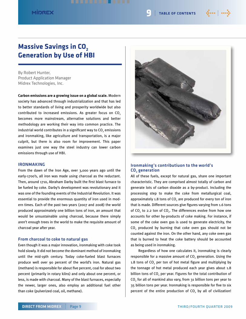
reSULtS: eXPerIence at aK SteeLFor nearly two decades, AK Steel has been adding hot briquetted
iron (HBI) to the charge mix of their blast furnace. This is quite
similar to the practice of adding prepared scrap or other metallic
sources of iron (used grinding balls, for instance) to a blast
furnace. It greatly enhances the productivity of the furnace while
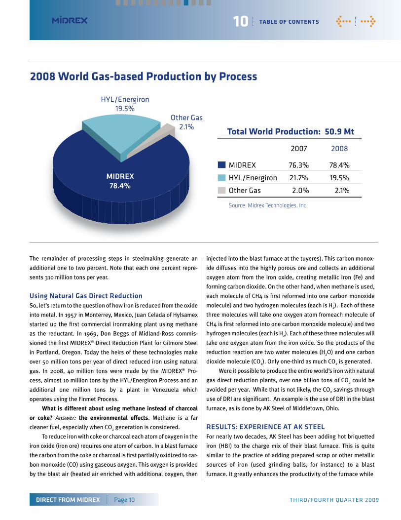
2008 World Gas-based Production by Process
total World Production: 50.9 Mt
2007 2008
MidREX 76.3% 78.4%
hYL/Energiron 21.7% 19.5%
other Gas 2.0% 2.1%
Source: Midrex Technologies, Inc.
mIDreX 78.4%
hYL/Energiron 19.5%
other Gas2.1%
11 taBle of contents
DIrect From mIDreX Page 11 thiRd/fouRth quARtER 2009
< >
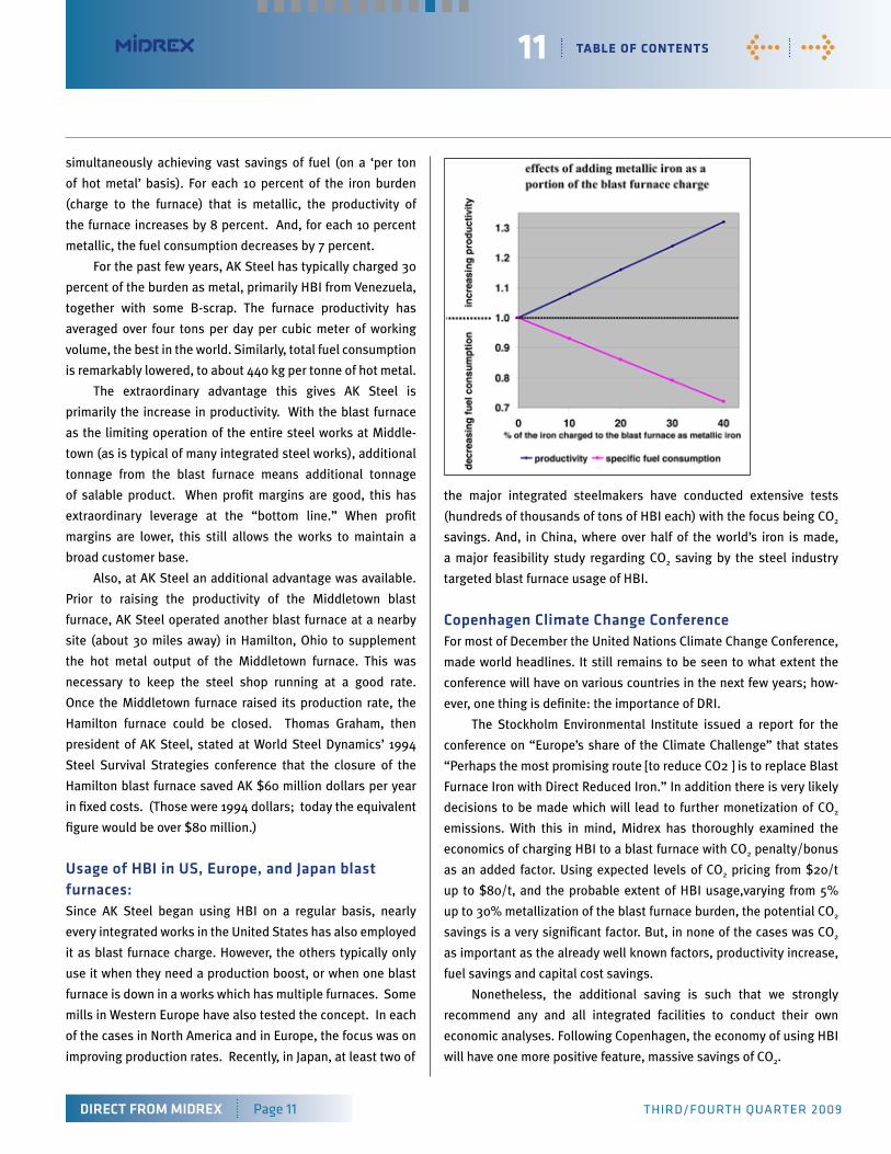
simultaneously achieving vast savings of fuel (on a ‘per ton
of hot metal’ basis). For each 10 percent of the iron burden
(charge to the furnace) that is metallic, the productivity of
the furnace increases by 8 percent. And, for each 10 percent
metallic, the fuel consumption decreases by 7 percent.
For the past few years, AK Steel has typically charged 30
percent of the burden as metal, primarily HBI from Venezuela,
together with some B-scrap. The furnace productivity has
averaged over four tons per day per cubic meter of working
volume, the best in the world. Similarly, total fuel consumption
is remarkably lowered, to about 440 kg per tonne of hot metal.
The extraordinary advantage this gives AK Steel is
primarily the increase in productivity. With the blast furnace
as the limiting operation of the entire steel works at Middle-
town (as is typical of many integrated steel works), additional
tonnage from the blast furnace means additional tonnage
of salable product. When profit margins are good, this has
extraordinary leverage at the “bottom line.” When profit
margins are lower, this still allows the works to maintain a
broad customer base.
Also, at AK Steel an additional advantage was available.
Prior to raising the productivity of the Middletown blast
furnace, AK Steel operated another blast furnace at a nearby
site (about 30 miles away) in Hamilton, Ohio to supplement
the hot metal output of the Middletown furnace. This was
necessary to keep the steel shop running at a good rate.
Once the Middletown furnace raised its production rate, the
Hamilton furnace could be closed. Thomas Graham, then
president of AK Steel, stated at World Steel Dynamics’ 1994
Steel Survival Strategies conference that the closure of the
Hamilton blast furnace saved AK $60 million dollars per year
in fixed costs. (Those were 1994 dollars; today the equivalent
figure would be over $80 million.)
Usage of HBI in US, europe, and Japan blast furnaces:Since AK Steel began using HBI on a regular basis, nearly
every integrated works in the United States has also employed
it as blast furnace charge. However, the others typically only
use it when they need a production boost, or when one blast
furnace is down in a works which has multiple furnaces. Some
mills in Western Europe have also tested the concept. In each
of the cases in North America and in Europe, the focus was on
improving production rates. Recently, in Japan, at least two of
the major integrated steelmakers have conducted extensive tests
(hundreds of thousands of tons of HBI each) with the focus being CO2
savings. And, in China, where over half of the world’s iron is made,
a major feasibility study regarding CO2 saving by the steel industry
targeted blast furnace usage of HBI.
copenhagen climate change conferenceFor most of December the United Nations Climate Change Conference,
made world headlines. It still remains to be seen to what extent the
conference will have on various countries in the next few years; how-
ever, one thing is definite: the importance of DRI.
The Stockholm Environmental Institute issued a report for the
conference on “Europe’s share of the Climate Challenge” that states
“Perhaps the most promising route [to reduce CO2 ] is to replace Blast
Furnace Iron with Direct Reduced Iron.” In addition there is very likely
decisions to be made which will lead to further monetization of CO2
emissions. With this in mind, Midrex has thoroughly examined the
economics of charging HBI to a blast furnace with CO2 penalty/bonus
as an added factor. Using expected levels of CO2 pricing from $20/t
up to $80/t, and the probable extent of HBI usage,varying from 5%
up to 30% metallization of the blast furnace burden, the potential CO2
savings is a very significant factor. But, in none of the cases was CO2
as important as the already well known factors, productivity increase,
fuel savings and capital cost savings.
Nonetheless, the additional saving is such that we strongly
recommend any and all integrated facilities to conduct their own
economic analyses. Following Copenhagen, the economy of using HBI
will have one more positive feature, massive savings of CO2.
12 taBle of contents
DIrect From mIDreX Page 12 thiRd/fouRth quARtER 2009
< >
mIDreX news & Views
(CHARLOTTE, NC, USA) Jindal Steel & Power Limited (JSPL)
has announced that it will build a 1.8 million ton per year coal
gasification-based MIDREX® Direct Reduction Plant in Angul,
Orissa, India. The new MIDREX® Module will pair commercially
available gasification technology from Lurgi GmbH of Germany,
together with a 7.15 meter MIDREX® Shaft Furnace to produce
direct reduced iron (DRI) for use in meltshop applications. This
will be the first time a Lurgi gasifier will be paired will a MIDREX®
Furnace; the new installation will use indigenous coal and iron ore.
The new MIDREX® Plant will have the flexibility to produce
both cold and hot DRI (HDRI) for a new greenfield meltshop to
be supplied by SMS Siemag AG of Germany and will use a hot
transport conveyor similar to that installed at Hadeed Module E
in Saudi Arabia. This commercially proven system is supplied by
AUMUND Fördertechnik of Germany.
The Angul MIDREX Plant will utilize syngas produced in the
gasification plant to produce high quality DRI for melting in an EAF.
Coal gasification is the process that converts coal to Synthesis gas
by partial oxidation using oxygen and superheated steam as the
reactants. The synthesis gas mainly consists of carbon monoxide,
hydrogen and methane which will be utilized as a reducing agent
for the iron oxide to produce DRI in the MIDREX Shaft Furnace.
The world’s first application of coal gasification to produce DRI
in a MIDREX Plant started up in 1999 at ArcelorMittal Steel South
Africa (formerly Saldanha Steel). This facility includes a COREX®
Plant, supplied by Siemens VAI, which uses a melter/gasifier to
simultaneously produce pig iron and a by-product synthesis gas
that feeds a MIDREX MEGAMOD® Shaft Furnace.
The Coal Gas MIDREX® Direct Reduction Plant is an
economica land environmentally sound solution for the iron and
steel industry in areas of the world where natural gas as a fuel is
not a viable option.
A coal gasification plant can use a wide range of low cost
fuels, such as bituminous and sub-bituminous coal, lignite, pet
coke, and petroleum refinery bottoms to generate a synthesis
gas. This syngas can be an acceptable reducing gas source for
producing DRI in a MIDREX Plant.
JInDaL SteeL & Power LImIteDhttp://www.jindalsteelpower.com
With an annual turnover of over US $2.00 billion (Rs. 10,000
crore), Jindal Steel & Power Limited (JSPL) forms a part of the US
$12 billion (over Rs. 60,000 crore) Jindal Group. JSPL is a leading
player in steel, power, mining, oil & gas and infrastructure.
JSPL has consistently tapped new opportunities by
increasing production capacity, diversifying investments, and
leveraging its core capabilities to venture into new businesses.
JSPL’s investment commitments in steel, power, oil & gas and
mining have touched more than US $30 billion (Rs. 1,50,000
crore). The company, today, is the largest private sector investor
in the state of Chhattisgarh with a total investment commitment
of over US$6.25 billion (Rs. 31,250 crore).
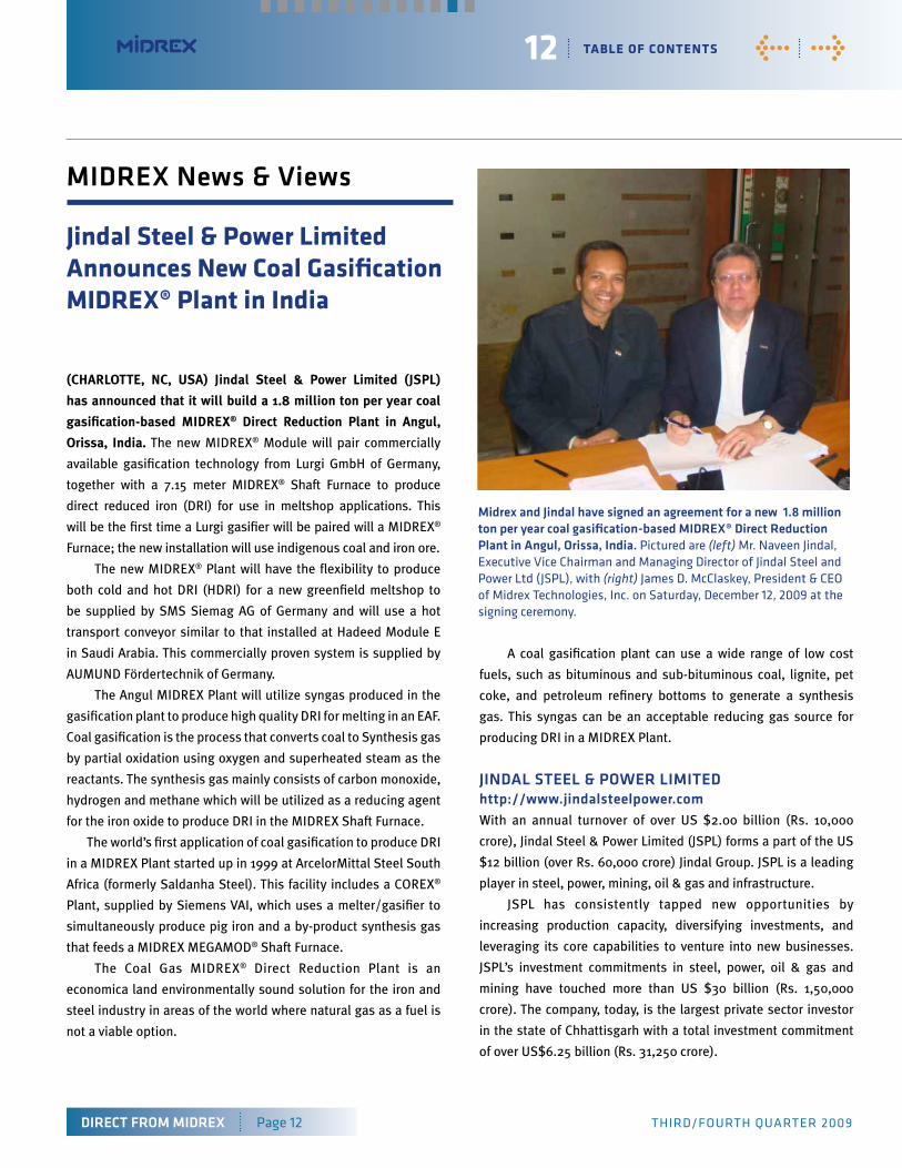
Jindal steel & Power limited announces new coal Gasification MIdreX® Plant in India
midrex and Jindal have signed an agreement for a new 1.8 million ton per year coal gasification-based mIDreX® Direct reduction Plant in angul, orissa, India. Pictured are (left) Mr. Naveen Jindal, Executive Vice Chairman and Managing director of Jindal Steel and Power Ltd (JSPL), with (right) James d. McClaskey, President & CEo of Midrex technologies, inc. on Saturday, december 12, 2009 at the signing ceremony.
13 table of contents
Direct From miDrex Page13 third/fourthquArtEr2009
<
miDrex News & Views
Christopher M. Ravenscroft: Editor
DIRECT FROM MIDREX is published quarterly by
Midrex Technologies, Inc.,
2725 Water Ridge Parkway, Suite 100, Charlotte,
North Carolina 28217 U.S.A.,
Phone: (704)373-1600 Fax: (704)373-1611,
Web Site: www.midrex.com under agreement
with Midrex Technologies, Inc.
The publication is distributed worldwide by email
to persons interested in the direct reduced iron
(DRI) market and its growing impact on the iron
and steel industry.
©2009 by Midrex Technologies, Inc.
To subscribe please register at www.midrex.com
to receive our email service.
coNtactiNg miDrex
General E-mail:
Phone: (704) 373-1600
2725 Water Ridge Parkway
Charlotte, NC 28217 USA
General Press/Media Inquiries
Christopher M. Ravenscroft
Phone: (704) 378-3380
With much of Midrex’s present and future direct reduction business in the Middle East and Eastern Europe/CIS, this office
provides an exceptional location for holding meetings with potential clients, suppliers, and others. In addition, it will prove useful
in the future for coordinating and managing projects.
A further benefit is that given London’s preeminence in global financing, there is ready access to a wealth of commercial and
investment banks, financial consultants, and other financial expertise.
Midrex opens UK office Midrex is proud to announce its first European Office, Midrex UK, Ltd. Located in the heart of London, England at 2 London Bridge, Midrex UK marks a strategic move for the company to position Midrex Technologies, Inc. for the future by increasing projects coordination throughout the world.


![[PPT]PowerPoint Presentation - SIMA. Providing input …. Presentations 2016 (attached) 9... · Web viewPresented by Midrex technologies, inc. Midrex® MXCOL® DR Plant IntegratedwithSES](https://img.pdfslide.us/doc/110x75/5aa60b4f7f8b9afa758e0339/pptpowerpoint-presentation-sima-providing-input-presentations-2016-attached.jpg)