Embed Size (px)
Citation preview

Dimensioning Dimensioning symbols Symbols are used to indicate geometrical features relating to a dimension. Symbol proportions are related to the height (h) of the characters used on a particular drawing. Table 1.6 shows symbols in common use.
Dimension and projection lines These lines are thin, continuous type B lines drawn outside the outline wherever possible.
Projection lines are used as follows: 1. to project from one view to another in order to
transfer detail (refer to Figure 3.4) 2. to allow dimensions to be inserted-projection
lines indicate the extremities of a dimension Dimension lines are necessary to indicate the
extent of a measurement. Figure 1.19 shows the use of projection and
dimension lines with appropriate measurements indicating dimension line spacing, projection line gap and extension.
Arrowheads are drawn open / ,,"" ~"" "" long and 1 mm wide
Figures should be approximately 2.5 mm high
rejection lines re thin lines nd may cross ~ ver when ecessary
p a a o n
~ N
\
0 N
~
~aCing between dimension
36
Figure is normally pia ced lines and outline should be equal and about 12 to 15 mm above the line in the
d"lrection of the arrowheads and readable from bottom or right-hand side
Fig. 1.19 Use of projection and dimensioning lines
Table 1 6 Dimensioning symbols
Symbol Drawing col/out
L--L _~9'>12 "T--()'J-t Diameter ,
R----t c(RfO
1 Radius
O=f°·7h _*Of2
Square
are thin lines r Dimension lines
2 mm past dimen slon line
22
8
~lmmgap
Ar rowheads should uch projection to
lin of
es at extremities the dimension
/ <0 ~ "'
""'- Arrowhea ds are placed
10
~, on the out side of projection
mailer dimensions Jines for s
Description
n ion lin is dra Dime 5 e wn parallel to direction of measurement and placed outside the view where possible
The symbol is placed In front of the dimension and indicates that it refers to the diameter of a circle, hole, cylinder or other circular feature (Fig. 1.25).
The symbol is placed in front of the dimension and indicates that it refers to the radius of part of a circle (Fig. 1.26).
The symbol is placed in front of the dimension and Indicates that it refers to the width across the flats of a square section (Fig. 1.29).
(continued)
15
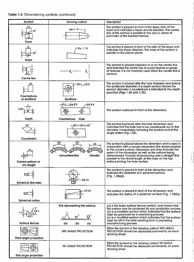
Table 1.6 Dimensioning symbols (continued)
Symbol Drawing callout Description
~ The symbol Is placed in front of the slope ratio of the
30' +~IB-taper and Indicates a taper and Its direction. The centre h line of the symbol is parallel to the axis or plane of
r---QJ symmetry of the tapered feature.
Taper
2h cS;0
The symbol Is placed In front of the ratio of the slope and
F~30' Indicates the slope direction. The base of the symbol Is parallel to the datum plane.
Slope
t=f 2'h l! The symbol Is placed adjacent to or on the centre line and Indicates the centre line of a part, feature or group
Ilhl:::T --t,-- of features. It is not normally used when the centre line is
I obvious.
Centre line
n ~¢6LJ¢12 The symbol Is placed after the hole diameter and before the spoHaced diameter. If a depth symbol follows the k-LJ second diameter a counterbore Is Indicated to the depth
! specified (Figs 1.34 and 1.35). Counterbore or spotfoce SpoHace
h {LJ¢8H r¢6n
0.6h1=-~i ] The symbol Is placed in front of the dimension. -{f)- -$-Depth Counterbore Hole
90' I ~i~¢lro. The symbol Is placed after the hole dimension and
V~ indicates that the hole has to be countersunk out to the diameter Immediately following the symbol and at the
-r angle stated (Fig. 1.33).
Countersink
~A~ The symbol Is placed above the dimension and Is used In conjunction with a curved dimension line drawn parallel
O~ to the curved surface. Dimension end lines indicate the extent of the dimension as well as the surface being
circumferential chordal dimensioned. Chordal dimensioning uses a straight line parallel to the chord length, In this case on the top
Curved surface or surface joining the hole centres. arc length
sq,=t -~S¢20 The symbol Is placed In front of the dimension and Indicates the diameter of a spherical surface (Fig. 1.29(a»).
Spherical diameter
SR-+ _BSR20 The symbol is placed in front of the dimension and , indicates the radius of a spherical surface (Fig. 1.28(b)).
Spherical radius
1.'f0.02t h line representing the surface (a) is the basic surface texture symbol, and means that
the surface may be produced by any production process
; ij", :i"",;$t (b) Is a modified symbol which indicates that the surface
60' must be produced by a machining process (c) Is a modified symbol which Indicates that the surface must be left In the state resulting from a preceding
Surface texture (a) (b) (c) manufacturing process.
1·@)·Ej·1 Either the symbol or the drawing callout '3RD ANGLE 3RD ANGLE PROJECTION PROJECTION' should be displayed prominently on each
drawing sheet. Third angle projection
Either the symbol or the drawing callout '1ST ANGLE
IS-@JI 1 ST ANGLE PROJECTION PROJECTION' should be displayed prominently on each drawing sheet.
First angle projection

Figure 1.20 illustrates correct and incorrect methods of employing centre lines and projection lines for dimensioning purposes.
, !
i
~1Yh I t .. \D'. . _.-$-------$-.- .-.l
I -j
(a) correct
I I
, ( 1\ I \ ..... I
- A-. . $ -'+' I
(b) incorrect
Fig. 1.20 Use of centre and projection lines in dimensioning
Linear dimensions These should preferably be expressed in millimetres. It is not necessary to write the symbol 'mm' after every dimension. A general note such as 'all dimensions are in millimetres' in the title block is sufficient.
Angular dimensions Angular dimensions should be stated in degrees; in degrees and minutes; or in degrees, minutes and seconds; for example 36.5°, 36°30', 36°29'30". A zero should be used to indicate an angle less than one degree, for example 0°30'0.5°.
Methods of dimensioning Two methods of indicating dimensions are in common use:
1. unidirectional, where the dimensions are drawn parallel to the bottom of the drawing, that is horizontal
2. aligned, where the dimensions are drawn parallel to the related dimension line and are readable from the bottom or right-hand side of the drawing
Dimensions and notes indicated by leaders should use the unidirectional method as illustrated in Figure 1.21.
w _~:s k: fO_~ ,
"
\ I 040 24.75
2S!:O.25 2S .25
\ I 135° =f 2f=
012
.tt{ _Etr~S
(a) unidirectional
~ $' k: ' "" /
(b) aligned
Fig. 1.21 Methods of dimensioning
17

</180
</160
</140
</125
Fig. 1.22 Use of staggered dimensions
Staggered dimensions Where a number of parallel dimensions are close together they should be staggered to ensure clear reading, as shown in Figure 1.22.
Functional dimensions Some dimensions are essential for the proper operation or function of a component. These are called functional dimensions and are always inserted on the component detail drawing. Functional dimensions may also be toleranced if necessary to ensure a proper working relationship with mating parts on assembly.
Overall dimensions When a length consists of a number of dimensions, an overall dimension may be shown outside the dimensions concemed (see Fig. 1.23). The end projection lines are extended to allow this. When an overall dimension is shown, however, one or more of the dimensions which make up the overall length is omitted. This is done to allow for variations in sizes which may occur during production. The omitted dimension is always a non-functional dimension, that is, one which does not affect the function of the product. Functional dimensions are those which are necessary for the operation of the product; these dimensions are essential.
Auxiliary dimensions When all the dimensions which add up to give an overall length are functional and/or convenient for manufacture, the overall dimension may be added as an auxiliary dimension. This is indicated by enclosing the dimension in brackets.
18
e
0 N
~ N
125
25 40 40
I V 1
-,/\<1>45_ j ~
1 V: T
0 .. ~ -
Fig. 1.23 Use of overall dimensions
Auxiliary dimensions are never toleranced and are in no way binding as far as machining operations are concerned. Figure 1.24 illustrates the use of an auxiliary dimenSion, narnely (100).
If the overall length dimension is important, then one of the intermediate dimensions is redundant, for example the dimension 42 from the left-hand end. This dimension may be inserted as an auxiliary.
4 2
17 r f-
20
42
58
1100)
Fig. 1.24 Use of auxiliary dimensions
Dimensions not to scale When it is desirable to indicate that a dimension is not drawn to scale, the dimension is underlined with a continuous, thick type A line, for example:
25.35 I • , I

Dimensions not complete Where a dimension is defining a feature that cannot be completely inserted on a drawing (for example, for a large distance or diameter) the free end is terminated in a double arrowhead pointing in the direction the dimension would take if it could be completed:
o N
"
I R 450
??:
7/
'" N
0 " N
" «> M
"
(a)
(b)
Dimensioning common features Diameters End view The symbol 0 shall be used to precede the dimension indicating a hole or cylinder. See Figure 1.25(a) for methods which are used on circles ranging from small to large diameters.
Side view This may be indicated, as shown in Figure 1.25(b), by the use of the symbol 0 preceding the dimension or by the use of leaders which are at right angles to the outline in conjunction with the symbol 0.
I I 10
I I/> 15
, 1/>20 1---'
8
I
10
i 1/>8
I
Fig. 1.25 Diameters dimensioned on end view (a) and side view (b)
19

Radii Figure 1.26 illustrates methods of dimensioning these features. A radius dimension is preceded by the letter R. Leaders should pass through or be in line with the centres of arcs to which they refer.
R5 R3
/ R 50
I
--f--
o o
'" or
Fig. 1.26 Methods of dimensioning radii
Small spaces
R 10
R20
Figure 1.27 illustrates methods of dimensioning small spaces which are too small to be dimensioned by normal methods.
3
3
3
I ~
Fig. 1.27 Dimensioning small spaces
20
Spherical surfaces These are dimensioned as shown in Figure 1.28. Note the distinction made between spherical diameters and spherical radii.
Sq,20
Sq,20
----- -hi'+--
(8) diameters
_~ __ ':45
1'.2
0
(b) radii
Fig. 1.28 Methods of dimensioning spherical surfaces
Squares The symbol 0 separated from the dimension by a single space indicates the size of a square as shown in Figure 1.29.
- I I
020
Fig. 1.29 Methods of dimensioning squares

+ 0.1 HOLE 012 0
</>12 'l'10
Fig. 1.30 Methods of dimensioning holes
Holes
M10
Holes either go right through a material or to a certain depth, and this must be specified as well as the diameter. If no indication is given, a hole is taken as going right through. Figure 1.30 above illustrates methods of dimensioning holes using both end and side views.
(a) holes equally spaced
¢>10LJ</>20'l'10 </>12LJ¢25
I </>~O I
Positioning holes Holes may be positioned by specifying the diameter of pitch circles as shown in Figure 1.31 or by specifying rectangular coordinates of centre distances as shown in Figure 1.32.
-~~---
, ----$-.
(a) co*ordinates of holes on a pitch circle (c) holes positioned by co*ordinate
dimensions
(b) holes unequally spaced
Fig. 1.31 Positioning holes by angular dimensions
I I I (b) symmetrical holes
:1-L .1 1_ , --BT-T
(d) holes positioned relative to an edge
Fig. 1.32 POSitioning holes by co-ordinate dimensions
21
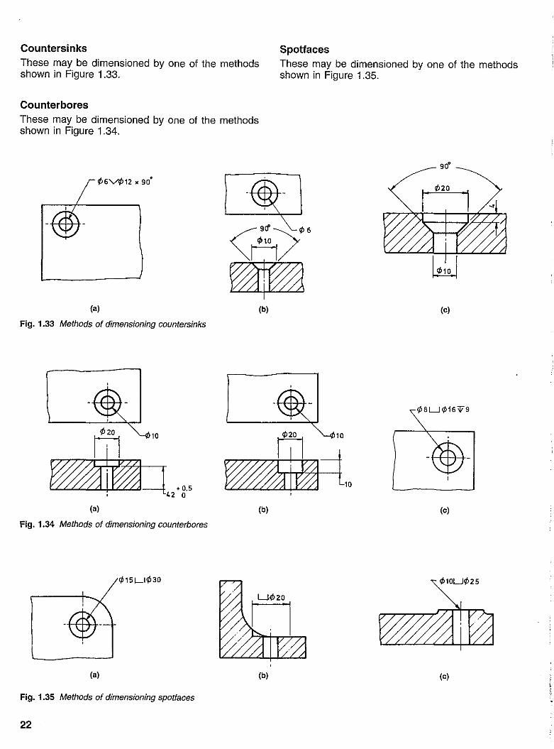
Countersinks These may be dimensioned by one of the methods shown in Figure 1.33.
Counterbores These may be dimensioned by one of the methods shown in Figure 1.34.
¢6V¢12 • 90'
(a)
Fig. 1.33 Methods of dimensioning countersinks
¢20 m -~."' , 42 0
10
(a)
Fig. 1.34 Methods of dimensioning counterbores
¢15LI¢30
(a)
Fig. 1.35 Methods of dimensioning spotfaces
22
(b)
(b)
(b)
Spotfaces These may be dimensioned by one of the methods shown in Figure 1.35.
90"
Mo
(c)
(c)
¢10U¢25
(c)

Fig. 1.36 Methods of dimensioning chamfers
Chamfers These may be dimensioned by one of the methods shown in Figure 1.36 above.
Keyways-square and rectangular Methods of dimensioning keyways in shafts and hubs, both parallel and tapered, are shown in Figure 1.37, together with suitable proportions for drawing rectangular keys. Enlarged details of key and keyways are shown in Figures 1.38 and 1.39.
DIA 12 r:l .,---- ---f-
proportions of rectangular key for drawing purposes
~~ /-,'1--- - -1---
parallel hub parallel shaft
Fig. 1.37 Methods of dimensioning keys and keyways
3r1'
Note: Tables 1.7 and 1.8 give dimensions and tolerances for square and rectangular parallel' keyways.
parallel keyway in a tapered shaft
~l:X
tapered keyway in a parallel hub
-j----_.
parallel keyway in a tapered hub
23

SECTION XX
Fig. 1.38 Enlarged detail of key and keyways
Table 1.7 Dimensions and tolerances for square parallel keyways
All dimensions in millimelres As amended July 1974
1 I 2 3 4 5 6 7 I 8 9 10 11 12 13 14 I 15
Shaft Key Keyway Isee Note)
width nominal b depth diameter radius
Isee Note) section tolerance for class of fit r d bxh shaftt, hub t,
width close and x free normal inter-
thickness terence
nom. over incl. shaft nom. tal. nom. tal. max. min.
shaft hub shaft hub and hub IH9) (010) IN9) IJ,9r IP9)
6 8 2x2 2 + 0.025 + 0.060 - 0.004 + 0.012 - 0.006 1.2 1 0.16 0.08 8 10 3x3 3 0 + 0.020 - 0.029 - 0.012 - 0.031 1.8 1.4 0.16 0.08
10 12 4x4 4 2.5 + 0.1 1.8 + 0.1 0.16 0.08 0 0
12 17 5x5 5 +0.030 + 0.078 0 + 0.015 - 0.012 3 2.3 0.25 0.16 0 + 0.030 -0.030 - 0.015 - 0.042
17 22 6x6 6 3.5 2.8 0.25 0.16
'The limits for tolerance J,9 are quoted from as 4500 (ISO limits and fits), to three significant figures. NOTE. The relations between shaft diameter and key section given above are for general applications. The use of smaller key sections is permitted if suitable for the torque transmitted. In cases such as stepped shafts when large diameters are required, for example to resist bending, and when fans, gears and impellers are fitted with a smaller key than normal, an unequal disposition of key in shaft with relation to the hub results. Therefore, dimensions d - t1 and d + t2 should be recalculated to maintain the h/2 relationship.
The use of larger key sections which are special to any particular application is outside the scope of this standard.
24

X SECTION X X
Fig. 1.39 Enlarged detail of key and keyways
Table 1.8 Dimensions and tolerances for rectangular parallel keyways
All dimensions in miJJjmetres
1 2 3 4 5 I 6 I 7 I 8 9 I 10 I 11 12 13 I 14 15
Shaft Key Keyway (see Nole)
widlh nominal b deplh diameter radius
(see Nole) section tolerance for class of fit r d bxh shaft I, hub I,
widlh free normal close x
thickness nom. shaft over incl. shaft hub shaft hub and hub nom. 101. nom. 101. max. min.
(H9) (010) (N9) (J,9), (P9)
22 30 8x7 8 + 0.036 + 0.098 0 + 0.018 - 0.015 4 3.3 0.25 0.16 30 38 10 x 8 10 0 + 0.040 - 0.036 - 0.018 -0.051 5 3.3 OAO 0.25
38 44 12 x 8 12 5 3.3 OAO 0.25 44 50 14 x 9 14 + 0.043 + 0.120 0 + 0.021 - 0.018 5.5 3.8 OAO 0.25 50 58 16 x 10 16 0 + 0.050 - 0.043 - 0.021 - 0.061 6 + 0.2 4.3 + 0.2 OAO 0.25 58 65 18 x 11 18 7 0 4.4 0 OAO 0.25
65 75 20 x 12 20 7.5 4.9 0.60 OAO 75 85 22 x 14 22 + 0.052 + 0.149 0 + 0.026 - 0.022 9 SA 0.60 OAO 85 95 25 x 14 25 0 + 0.065 - 0.052 - 0.026 - 0.074 9 SA 0.60 OAO 95 110 28 x 16 28 10 6A 0.60 OAO
110 130 32 x 18 32 11 7A 0.60 OAO 130 150 36 x 20 36 + 0.062 + 0.180 0 + 0.031 - 0.026 12 8A 1.00 0.70 150 170 40 x 22 40 13 9A 1.00 0.70 170 200 45 x 25 45 0 + 0.080 - 0.062 - 0.031 - 0.088 15 lOA 1.00 0.70 200 230 50 x 28 50 17 llA 1.00 0.70
230 260 56 x 32 56 20 + 0.3 12A + 0.3 1.60 1.20 260 290 63 x 32 63 + 0.074 + 0.220 0 + 0.037 - 0.032 20 0 12A 0 1.60 1.20 290 330 70 x 36 70 0 + 0.100 - 0.074 - 0.037 - 0.106 22 14A 1.60 1.20 330 380 80 x 40 80 25 15A 2.50 2.00
380 440 90 x 45 90 + 0.087 + 0.260 0 + 0.043 - 0.037 28 17A 2,50 2,00 440 500 100 x 50 100 0 + 0.120 - 0.087 - 0,043 - 0.124 31 19,5 2,50 2,00
"The limits for tolerance J,9 are quoted from as 4500 (ISO limits and fits), to three significant figures, NOTE. The relations between shaft diameter and key section given above are for general applications. The use of smaller key sections is permitted jf suitable for the torque transmitted. In cases such as stepped shafts when large diameters are required, for example to resist bending, and when fans, gears and impellers are fitted with a smaller key than normal, an unequal disposition of key in shaft with relation to the hub results. Therefore, dimensions d - I, and d + 12 should be recalculated to maintain the hl2 relationship.
Tne use of !arger key sections IS not permitted.
25

Keyways-Woodruff Methods of dimensioning Woodruff keyways in shafts and hubs, both parallel and tapered, are shown in Figure 1.40.
parallel hub
parallel shaft
Fig. 1.40 Methods of dimensioning Woodruff keys
/" :
is
(0)
INCLUDED ANGLE ('
- .-
(e)
Fig. 1.41 Methods of dimensioning tapers
26
<: Cl
Tapers Tapers are dimensioned by one of the four methods shown in Figure 1.41.
tapered hub
tapered shaft
-e..l:X
<: Cl
DI5T
(b)
~[+-- ]~ LL-i -LG----l)
(d)

Screw threads General representation The methods shown in Figure 1.42 are recommended for right-hand or left-hand representation of screw threads. The diameter (0 DIA) of a thread is the nominal size of the thread, for example for a 12 mm thread (M12, see p. 28), DIA = 12 mm.
(a) external thread: side and end view
Threads on assembly and special threads Figure 1.43(a) illustrates the method of representing two threads in assembly. Figure 1.43(b) shows the assembly of two members by a stud mounted in one of them. Special threads are usually represented by a scrap sectional view illustrating the form of the thread, as shown in Figure 1.43(c).
(b) external thread: section
DRILL POINT 120'
1--4--'CLEARANCE
(e) internal thread: outside view (d) internal thread: sectional view (e) internal thread: end view
Fig. 1.42 Methods of representing screw threads
STUD
(b) assembly 01 a slud in a blind hole
NUT
SPRING WASHER
MEMBER A
MEMBER B
Fig. 1.43 Methods of representing assembled and special threads
(a) threads in assembly
(e) square thread
27

Dimensioning full and runout threads When full and runout threads have to be distinguished, the methods of dimensioning shown in Figure 1.44 are recommended. Where there is no design requirement, the runout threads need not be dimensioned.
Dimensioning metric threads in holes Figure 1.45 (below) shows various methods used to dimension threaded holes. The diameter of the thread is always preceded by the capital letter M, which indicates metric threads.
The coarse thread series is dimensioned simply by the letter M followed by a numeral, for example M12. However, fine threads should show the pitch of
20
'j
I:
the thread as well, for example M12 x 1.25. The term 6H contained in the thread dimensions of Figure 1.45(b), (c) and (d) refers to the grade of tolerance to be used in the manufacture of these threaded holes. This tolerance combined with a similar tolerance on the mating screw provides a certain 'fit' when the screw is assembled into the threaded hole. The system used for threaded 'fits' is the same as that used for plain shaft and hole 'fits' described on page 54.
If it is not important, the runout threads need not be dimensioned. However, in blind holes it is often important to have fully formed threads for a certain depth, and dimensioning must be provided to control this.
20 MIN
[ (a) dimensioning length of full thread
II [ I----t -I+--~ -(b) dimensioning to end of full thread
25 MIN
I, --+-[ t ~
.1 28 MAX
(e) dimensioning length of full thread and runout
Fig. 1.44 Methods of dimensioning threaded members
M12 20 MIN LG FULL THO
(a)
M18 x 1.5- 6H 22 MIN LG FULL THO
(b) M18
Fig. 1.45 Methods of dimensioning threads in holes
28
(e)
o ~ N N
M20x l.S-6H 20 MIN LG FULL
THO 26 MAX INCL RUNQUT
(d)

The Australian metric thread profile Figure 1.46 shows the profile of the internal and external metric threads, which are suitable for single point screw cutting at maximum material condition according to AS 1721 :1985. If the rounded projection is not used, a flat should be ground on the appropriate tool to the values of Wn and W, and the corners will round off as the tool wears.
INTERNAL THREAD
/
Detail A
Fig. 1.46 Profile of the Australian metric thread
The ISO metric thread Figure 1.47 shows the profile of the ISO metric thread, together with proportions of the various defined parts of the thread.
p = pitch of thread
H = 0.866 P H S=0.108p
3H "8 = 0.325 P
H 4 = 0.217 P
5H "8 = 0.541 P
MAJOR DIAMETER
I PITCH
DIAMETER
I MINOR DIAMETER
I
In practice the crest may be rouhded
Detail A
Internal thread (Detail A)
h, = 0.577 P R, = 0.072 P W,(max) = 0.072 P W,(min) = 0
p
Fig. 1.47 Basic profife and proportions of the ISO metric thread
p
4
External thread (Detail B)
h. = 0.604 P R,=0.125P W,(max) = 0.177 P W.(min) = 0.144 P
:I:
"'''''
29

/ /
4.5
4
3.5
ISO metric coarse~ / I
ISO metric fine
~ /
3
2.5
E .§.
/ /'"
.,/ /'" /'"
/'" / --/ ._-
/
r _.
V /
V
.
'0 .. !
2 -5 '0
1.75 .s: £
.5 c:: 1
1 .25
1 0.8 0.7 0.5 OA
o 1 2 3 4 5 6 7 B 9 10 12 14 16 1 B 20 22 24 27 30 33 36 39 o
42 Diamete, (mm)
Fig. 1.48 Graphical comparison of metric threads
Graphical comparison of metric thread series ISO metric threads are of two kinds: coarse and fine thread. A graphical comparison of these two series is shown in Figure 1.48.
Tapping size and clearance holes for ISO metric threads Tapping sizes and clearance holes for metric threads are shown in Table 1.9 (page 32). In this table column 1 represents first and second choices of thread diameters. The sizes listed under second choice should be used only when it is not possible to use sizes in the first choice column.
The pitches listed in column 2 are compared on the graph in Figure 1.48. These pitches, together with the corresponding first and second choice diameters of column 1, are those combinations which have been recommended by the ISO as a selected 'coarse' and 'fine' series for screws, bolts, nuts and other threaded fasteners commonly used in most general engineering applications. Column 3 is the tapping size for the coarse and fine series. These values represent approximately 83 per cent full depth of thread, and can be calculated simply by the formula:
30
tapping drill size = outside diameter - pitch 3.3 = 4 - 0.7
Sometimes the drill size has to be rounded off to the next largest stock drill size; this can be obtained from Table 1.10 (page 33).
Column 4 of Table 1.9 gives tapping sizes for coarse threads in mild steel only; these will give approximately 71 per cent of the full depth of thread. In most general engineering applications this depth of thread is sufficient and desirable for the following reasons:
1. Tapping 83 per cent depth of thread necessitates about three times more power than tapping 71 per cent depth of thread.
2. The possibility of tap breakage is greater as the depth of thread increases.
3. The 83 per cent depth of thread has approximately 5 per cent more strength than the 71 per cent depth of thread.
4. The amount of metal removed from a 71 per cent depth of thread is much less than that removed for 83 per cent depth of thread.
There are cases when a deeper thread is necessary, for example on machines and in situations where movement in the mating threads is to be kept to a minimum.
Column 5 of Table 1.9 gives three classes of clearance holes recommended for the various sizes of metric threads.