Embed Size (px)
Citation preview

| 1W
l[ ?
g_
'43,-4N r"-
tO tO ooI m
N "_ o
_-- ..J J w
oO ..J w
w-,.J (_. c_ ,0
Ballelle• . • Putting Technology To Work
.... 2
3o3_o 7
REPORT"PHASE I
SPACE STATION
LONG TERM
LUBRICATION
ANALYSIS
PHASE I
PRELIMINARY
TRIBOLOGICAL
SURVEY
To
GEORGE C. MARSHALL SPACE FLIGHT
CENTER
MARSHALL SPACE FLIGHT CENTER,
ALABAMA
SEPTEMBER 21, 1990
https://ntrs.nasa.gov/search.jsp?R=19920024972 2018-07-19T01:53:50+00:00Z
w
_m
g
z
tl
i
lu
g
i
mii
til
m
|
J
IBg
m
!J
mII
J
m_
mu
|
|

! !z!
zr
! i
__=:_
NASA Marshall Space Flight CenterAttn:
Marshall Space Flight Center, AL 35812
AP52-F
CN22D
AT01
BF30
CC01/Wofford
EM13B-21
KA02
EH14/Fred Dolan
_ NASA Scientific and Technical
Information Facility
Attn: Accessioning DepartmentP.O. Box 8757
Baltimore/Washington International
Airport, Maryland 21240
E.E. Montgomery
SRS Technologies
990 Explorer Blvd. N.W.
Cummings Research Park West
Huntsville, AL 35808
Monthly
Progress ....
Repo.rt
3
1
0
1
i
1
5 + repro
1 + repro
Final
Progress
0 _
0
0
0
1
0
0
2
0
Final
Progress
Approved
1
5
1
1
1
1
1
10 + repro
1 + repro
Financial
Management
Report
1
0
0
1
0
1
1
1
0
!
um
_i l_
ml
Imlm
_m
ms
im
m
J
m
um
mnmm
I
m
lil
!
L J
M
i
m
Ill
m
k..:PHASE I REPORT
.
on
SPACE STATION LONG TERM
LUBRICATION ANALYSIS
PHASE I PRELIMINARY TRIBOLOGICAL SURVEY
!
s
tO
. H
GEORGE C. MARSHALL SPACE FLIGHT CENTER
Marshall Space Flight Center, Alabama 35812
September 21, 1990
by
r_ __
K.F. Dufrane, J.W. Kannel, and J.A. Lowry
BATTELLE
505 King Avenue
Columbus, Ohio 43201
and
E.E. Montgomery
SRS Technologies
990 Explorer Blvd., NW
Huntsville, AL 35806

i
i
in
i
H
H
= _
i
i
I
|
i
_e
gig
_q
k_..
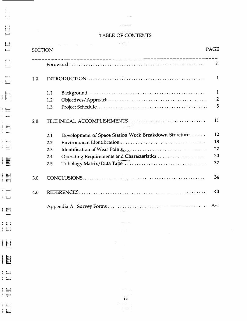
TABLE OF CONTENTS
PAGE
r_,,.1
] [_7]
_L
a, _4
INTRODUCTION ....................................... 1
SUMMARY .......................................... 5
SPACE STATION LUBRICATION REQ_REMENTS ................ 6
Lubricant Considerations ......... 10
Solid Film Lubrication .................................. 10
Advantages and Disadvantages ........................... 10
i :
Selection of Solid Lubricants ............................ 11
Rolling Contacts ................................... 13
Liquid/Grease Lubrication . ........... 19
Advantages and Disadvantages ........................... 19
Thermo-Vacuum Evaporation ........................... 19
Friction and Wear Performance .......................... 22
IDENTIFICATION OF SPECIFIC TRIBOLOGICAL COMPONENTS ...... 26
REFERENCES ........................................ 28
BIBLIOGRAPHY ....................................... 30
APPENDIX A. SRS TECHNOLOGIES SUBCONTRACTOR REPORT ..... 37
Figure 1.
Figure 2.
Figure 3.
LIST OF FIGURES
PAGE
Overall Layout of Space Station ........................ 7
Comparison of Ball Bearing Operating Torques .............. 16
Dependence of Vapor Pressure on Temperature for a PerfluoroEther Lubricant .................................. 21
n
m
m
B
m
i
i
I
i
I
m
mm_u
z
I
m :
I
m
I
hil
=
ld
k:i
i: ==_
LL!
i _
i i
Table 1.
Table 2.
Table 3.
Table 4.
Table 5.
Table 6.
Table 7,
Table 8.
Table 9.
Table 10.
Table 11.
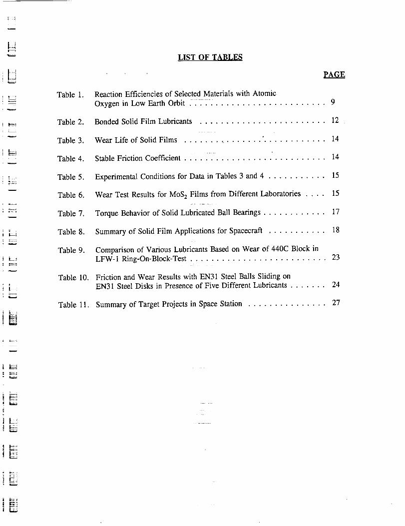
LIST OF TABLES
_AGE
Reaction Efficiencies of Selected Materials with Atomic
Oxygen in Low Earth Orbit . . . 9
Bonded Solid Film Lubricants ........................ 12
Wear Life of Solid Films ......... " 14
22 ....
Stable Friction Coefficient ........................... 14
Experimental Conditions for Data in Tables 3 and 4 ........... 15
Wear Test Results for MoS 2 Films from Different Laboratories .... 15
Torque Behavior of Solid Lubricated Ball Bearings ............ 17
Summary of Solid Film Applications for Spacecraft ........... 18
Comparison of Various Lubricants Based on Wear of 440C Block in
LFW-1 Ring-On-Block-Test .......................... 23
Friction and Wear Results with EN31 Steel Balls Sliding on
EN31 Steel Disks in Presence of Five Different Lubricants ....... 24
Summary of Target Projects in Space Station ............... 27
1m _, ,,
I E;i
L,..- _
t
iE

w
w
mliJI
m
I
rnl
mm
m
J
m
!l
Z
U
I
U
m
!
w _
It ;
t
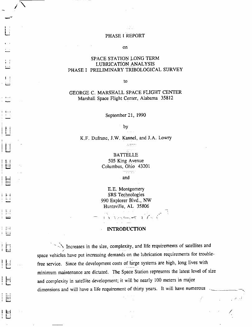
PHASE I REPORT
on
PHASE I
SPACE STA_ON LONG TERM
LUBRICATION ANALYSIS
PRELIMINARY TRIBOLOGICAL SURVEY
to
GEORGE C. MARSHALL SPACE FLIGHT CENTER
Marshall Space Flight Center, Alabama 35812
c_
r_
u
September 21, 1990
by
K.F. Dufrane, J.W. Kannel, and J.A. Lowry
BATTELLE
505 King Avenue
Columbus, Ohio 43201
and
E.E. Montgomery
SRS Technologies
990 Explorer Blvd., NW
Huntsville, AL 35806
INTRODUCTION
---C'_ increases in the size, complexity, and life requirements of satellites andf .....
space vehicles have put increasing demands on the lubrication requirements for trouble-
free service. Since the development costs Of large systems are high, long lives with
minimum maintenance are dictated. The Space Station represents the latest level of size
and complexity in satellite development; it will be nearly 100 meters in major
dimensions and will have a life requirement of thirty years. It will have numerous
/
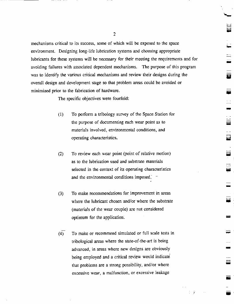
mechanisms critical to its success, some of which will be exposed to the space
environment. Designing long-life lubrication systems and choosing appropriate
lubricants for these systems will be necessary for their meeting the requirements and for
avoiding failures with associated dependent mechanisms. The purpose of this program
was to identify the various critical mechanisms and review their designs during the
overall design and development stage so that problem areas could be avoided or
minimized prior to the fabrication of hardware.
The specific objectives were fourfold:
(1) To perform a tribology survey of the Space Station for
the purpose of documenting each wear point as to
materials involved, environmental conditions, and
operating characteristics.
(2)
(3)
(4)
To review each wear point (point of relative motion)
as to the lubrication used and substrate materials
selected in the context of its operating characteristics
and the environmental conditions imposed.?i
To make recommendations for improvement in areas
where the lubricant chosen and/or where the substrate
(materials of the wear couple) are not considered
optimum for the application.
To make or recommend simulated or full scale tests in
tribological areas where the state-of-the-art is being
advanced, in areas where new designs are obviously
being employed and a critical review would indicate
that problems are a strong possibility, and/or where
excessive wear, a malfunction, or excessive leakage
u
w
= =
m
m
M
m
l
mR
I
m
m
=
I
I
I
I
u
mm
i
m
I
L_H
Lk
i
3
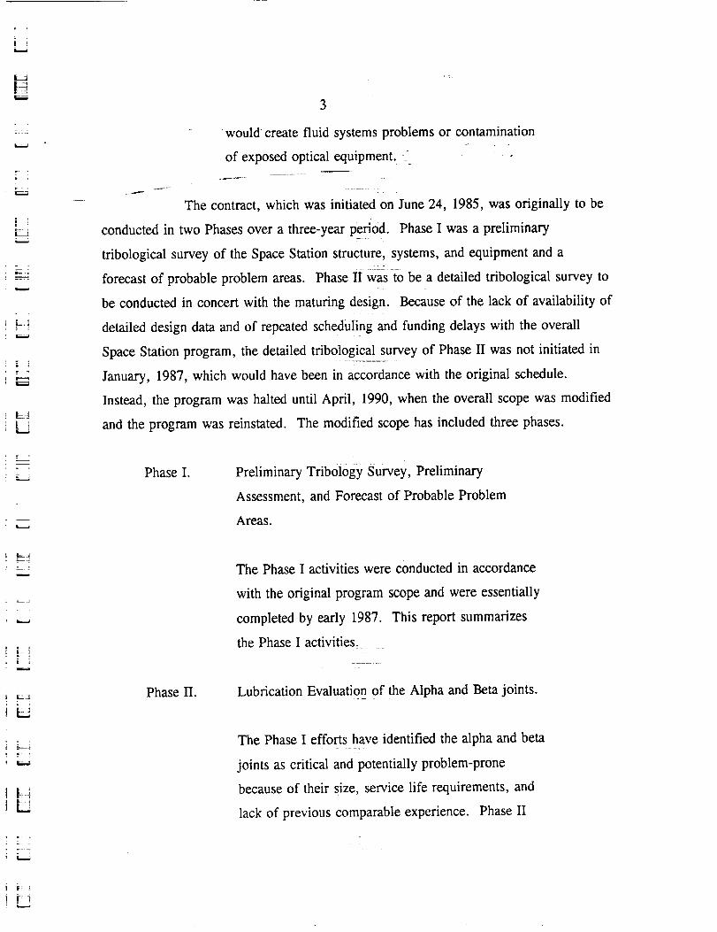
would •create fluid systems problems or contamination" t
of exposed optical equipment. -=
The contract, which was initiated on June 24, 1985, was originally to be
conducted in two Phases over a three-year period. Phase I was a preliminary
tribological survey of the Space Station structure, systems, and equipment and a
forecast of probable problem areas. Phase II Was to be a detailed tribological survey to
be conducted in concert with the maturing design. Because of the lack of availability of
detailed design data and of repeated scheduling and funding delays with the overall
Space Station program, the detailed tribological survey of Phase II was not initiated in
January, 1987, which would have been in accordance with the original schedule.
Instead, the program was halted until April, 1990, when the overall scope was modified
and the program was reinstated. The modified scope has included three phases.
Phase I. Preliminary Tribol0gy Survey, Preliminary
Assessment, and Forecast of Probable Problem
Areas.
JL
_L
Phase II.
The Phase I activities were conducted in accordance
with the original program scope and were essentially
completed by early 1987. This report summarizes
the Phase I activities,
Lubrication Evaluation of the Alpha and Beta joints.
The Phase I efforts have identified the alpha and beta
joints as critical and potentially problem-prone
because of their size, service life requirements, and
lack of previous comparable experience. Phase II

PhaseII.
(cont.)
4
will consistof a review of thesejoints. The intent is
to evaluatewhetheralphaandbetajoints of thecurrent
design(incorporatingreasonablemodificationsif found
necessary)are likely to meettherequirementsof
consistenttorqueandoutgassingspecificationsfor a
servicelife of 25 years. The reviewwill includethe
lubricationmethodology(grease,transferfilms, or
solid films) andthetrade-offsconsideredin arriving at
themethodology(maintenanceintervals,outgassing,
seals,friction levels,anddebrisgeneration). In
addition,a reviewwill be madeof the testsalready
performedin supportof thedesignand thosespecified
for future evaluations.The resultsof the review,
includinganevaluationof the currentdesignand
recommendationsfor modificationsor neededtests,
will bedocumentedin the PhaseII sectionof thefinal
report.
B
w
zmI
II
mm
m
u
m
mm
i
I
Phase III. Lubricant Selection Guide
Phase HI will consist of preparation of a practical
lubricant selection guide for use by designers of
Space Station components. While the potentially
available liquid and dry-film lubricants number in the
hundreds, a large percentage are not practical for
Space Station components because of such factors as
outgassing properties, creep properties, viscosity,
long-term stability, corrosive properties, or wear
protection. The purpose of the Phase III effort will
be to reduce the number of lubricants to a practical
I
z
mm
I
u
m
U
I
U
H
..=
_,_ _ i_ :
5
working number for designers to consider. Guides
will be given for the selection of specific lubricants
from the recommended list. The design guide will be
incorporated in the final report.
This report is to document the Phase I activities. It describes the general
Space Station requirements that will affect lubrication and the basic lubrication
approaches available to address these requirements. The report by SRS Technologies, a
major subcontractor on Phase I, is included in its entirety as Appendix A. SRS
Technologies had responsibility for documenting the Space Station components and
mechanisms regarding lubrication requirements.
HSUMMARY
J
L_
_-S__S_-
The Phase I activities began with a review of the various work packages
of the primary contractors to identify tribological points of interest (SRS Technologies)
and a review of pertinent literature to identify likely lubricants for use in the
tribological applications (Battelle). As de_is of the various tribological points were
identified, Battelle was to perform a review to assess the likelihood of success.
Difficulties were encountered in attaining the needed design details because of the early
stage of the design (details on loads and sizes were not available) and because of overall
program delays. Consequently, a comprehensive review could not be made of most of
the 72 specific components identified in the survey of 14 target projects. Of these, the
most critical by far were the alpha and beta joints because of their size, lack of prior
history, and their criticability to the Space Station. Since a change was made in
contractors for these joints from the time the Phase I survey was conducted, the
detailed design information obtained in the survey was useful only in a general sense...... i
Because of the importance of these joints, the modified scope for the Phase II activities
of the program concentrates specifically on these joints.
6
The literaturereview identifiedpapers,reports,andbooksdealingwith
developmentsin lubricantsfor aerospacemechanisms.Recentadvancesin solid
lubricantshaveinvolvedtheadditionsof antimonyandantimonycompoundsto improve
the friction and wearpropertiesof bondedmolybdenumdisulfidesolid lubricants. The
selectioncriteria are based on the longevity needed and the possible deterioration of the
binder from exposure to the space environment. Of the various candidate liquid (and
grease) lubricants, the perfluoro ethers have come to dominate the field because of their
low vapor pressure and acceptable lubricating properties. Friction and wear data and
flight history data are available to assist in the selection and application of the perfluoro
ethers. The Lubricant Selection Guide of Phase III will detail the specific preferred
lubricants for example families of tribological contacts and provide data on advantages,
disadvantages, and life-limiting considerations for their application.
SPACE STATION LUBRICATION REQUIREMENTS
The combination of size, complexity, and desired life of the Space
Station is unprecedented in satellite design. As shown in Figure 1, the overall layout of
the Space Station includes a central module that will be held in alignment to the surface
of the earth. Large solar panels to provide power will be attached through "alpha" and
"beta" joints to permit orienting the panels toward the sun. The size of the joints
(approximately 3 meters in diameter for the bearing at the alpha joint) and associated
structure demands that these beatings be capable of operation for the intended thirty
year life. Changing the beatings would require major unacceptable provisions for
astronaut time and for restraining the panel assembly. Inherent reliability of the
beating and lubrication systems for these large structures is therefore required.
The thirty year life will also expose components to 175,000 thermal
cycles. The range of these cycles will be controlled primarily by the optical properties
of the surfaces involved unless active thermal control is provided. Thermal cycles can
affect lubricants in several ways. For liquid lubricants, the immediate effect is a
change in viscosity. If the lower temperature extreme is below the pour point of the
w
l
W
i
m
mm
m
U
I
i
I
m
I
w
!
a
i
m
I

;- z
U
m 7
: 3 _L
[ .....
w
i
m
u
_LFIGURE 1. OVERALL LAYOUT OF SPACE STATION
L
8
liquid, it may be unable to reach the critical surfaces in the beating or mechanism
needing lubrication. Similarly, the high temperature extreme may lower the viscosity
to a level where the lubricant cannot function properly. High temperatures can also
degrade the lubricant through a variety of thermal degradation mechanisms. While dry
film (solid) lubricants are relatively unaffected by temperature cycles, the binding agent
must be chosen appropriately to avoid thermal degradation at the upper temperatures.
The thirty year life requirement introduces time-related lubrication
degradation mechanisms, which must also be considered. Evaporation, creep, and
degradation by atomic oxygen all represent potential problems that must be addressed in
the design of mechanisms and selection of lubricants. Evaporation and creep of liquid
lubricants present the dual problems of lubricant loss at the needed surface and of
potential contamination of optical surfaces by the lost lubricant. These problems are
controlled primarily by the basic chemical composition of the lubricant. Atomic
oxygen, however, presents a new challenge for spacecraft design in that a variety of
organic materials are attacked. Experiments on two Space Shuttle missions, Space
Transportation Systems 5 and 8 (STS-5 and STS-8), provided data that showed
materials containing carbon, silver, and osmium react with atomic oxygen to form
volatile • -0)ox_oes . Table 1 lists the reaction efficiencies for a representative set of
materials (2_. Because of the reactions with organic materials, liquid lubricants and dry
film lubricants having organic binders must be protected from exposure or selected with
a knowledge that continual degradation will occur. In the case of thin solid films using
an epoxy-based binder, exposure to atomic oxygen may degrade the binder in a matter
of days (2). For practical systems requiring exposure, therefore, inorganic binders, such
as silicates, may be required to avoid the problem.
I
I
I
i
i
m
m
mm
m '
i
mm
B
mn
m
m
m
I
I
mi

7 -
Ld
9
| _+++
w
TABLE 1. REACTION EFFICIENCIES OF SELECTED MATERIALS WITH
ATOMIC OXYGEN IN LOW EARTH ORBIT (REFERENCE 2)
Material
Kapton 3
Mylar 3.4
Tedlar 3.2
Polyethylene 3.7
Polysulfone 2.4
Graphite/epoxy
1034C 2.1
5208/T300 2.6
Epoxy 1.7
Silicones < 0.02*
White paint A276 0.3 to 0.4*
Black paint Z302 2.3*
Perfluorinated polymers
Teflon, TFE < 0.05
Teflon, FEP < 0.05
Carbon (various forms) 0.9 to 1.7
Silver (various forms) Heavily attacked
Reaction Efficiency, 10 .24 cm3/atom
IL
*Units of mg/cm 2 for STS-8 mission. Loss is assumed to occur in early part of
exposure; therefore, no assessment of efficiency can be made.
10
Lubricant Considerationsm
Lubricants can be divided into two basic classes: solid films and liquids.
Both types have been used extensively in space applications. Both have advantages and
disadvantages that must be carefully considered in their selection. The factors of
particular importance for Space Station lubrication are considered in this section.
Solid Film Lubrication
Advantages and Disadvantages
From Reference 3, the following lists the basic advantages and
disadvantages of solid film lubricants.
m
i
I
I
n
mI
Advantages of Solid Lubricants !
°
2.
3.
4.
5.
6.
7.
8.
9.
Do not collect grit.
Can be used under extremely high load conditions.
Excellent storage stability.
LOX and oxygen compatible (inorganically bonded films).
Suitable for use over wide temperature range.
Resistent to the effects of nuclear and gamma radiation.
No disposal problem.
Friction decreases with increasing load.
In some applications solid films will provide lubrication for the life of the
parts.
Disadvantages of Solid Lubricants
1. Limited amount of lubricant available.
.= =-
M
m
m
u
Z
I
m
B
J
m
m
- 4
|_r
_|_, L ¸_-
I .
.
3.
4.
.
6.
.
11
Friction coefficient higher than with hydrodynamic lubrication.
Provisions for the effective removal of wear debris must be provided.
Considerations must be given to removing heat from contact zone of
bearings and gears when using solid film lubricants.
More expensive (costly relubrication).
Avoidance of contamination during coating processes and assembly of
parts lubricated with solid film lubricants.
Elevated temperature cure cycle of some solid films will damage the
mechanical properties of some materials.
Selection of Solid Lubricants
i|iii
: -: i
i = z
]
Solid lubricants provide capabilities unavailable with liquid lubricants,
but they are not a universal lubricant. The requirements of some applications prevent
their use entirely. Also, there is no single solid lubricant that will meet all of the
requirements. Therefore, the selection of the basic class of lubricant (solid or liquid)
and the specific lubricant must consider the needs of the particular application and the
requirements of the system of which the application is a part.
The obvious advantages of solid films are that they add virtually no
weight to the system and create virtually no problems due to outgassing. The primary
disadvantages of solid films are that they have limited life and are very difficult to
replenish.
The three basic solid film lubricants that have traditionally been given the
most attention and used most extensively are:
• Graphite,
• Polytetrafluorethelene _TFE), and
• Molybdenum disulfide (MoS_.
Table 2 (4) lists several bonded films and application methods. Recent work in solid
films has involved some compositional variations in these lubricants primarily to

M
12m
U_
.<
©
©
.<E_
oma
oil
('_
c_
,e.b
c_
c_
r_
c__J
olU
c_
C_
+-t- _ -t- -t-
o_.._
-Jr + .4- + _ _-_
0 0 0 0 _
G_
_me
¢)
• --.,i _l_
J
m
J
HI
i
n
b
i
mI
ill
i
Jm
I
E
Hi
I
J
m _m _
III -
w
k.:13
achieve improved wear life and possibly reduced friction.
Bartz, Holeniski, and Xu (5) indicate that there exists optimum
concentrations for MoS 2 doped with materiais such as graphite and antimony
compounds to yield longer wear life than attainable with single components. A
comparison of wear lives as obtained in rub block experiments is given in Table 3, and
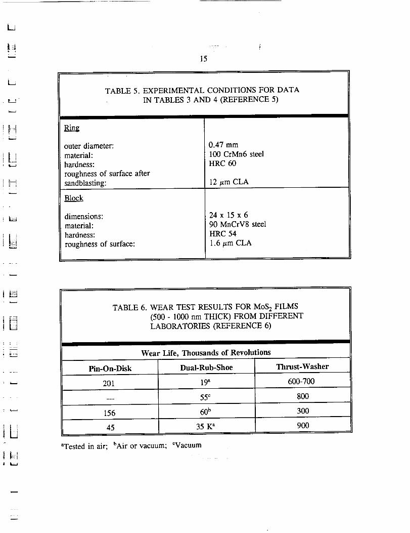
the friction coefficients are presented in Table 4. Table 5 shows the test conditions.
Wear lives of 100,000 cycles are possible with this approach, which should be adequate
for many components of Space Station. While graphite is probably inappropriate for
vacuum service. Bartz research indicates that solid films exist that should provide good
service life.
Fleshauer (6) is doing extensive work in evaluation of solid films,
especially MoS 2 formulations. Table 6 summarizes the wear lives obtained with three
different contact conditions. The pin-on-disi_ tests were run at a load of 700 MPa. The
results have shown that the wear life can be increased significantly if the MoS 2 is doped
with antimony. Again, a wear life of 105 cycles is shown to be possible.
Rolling Contacts
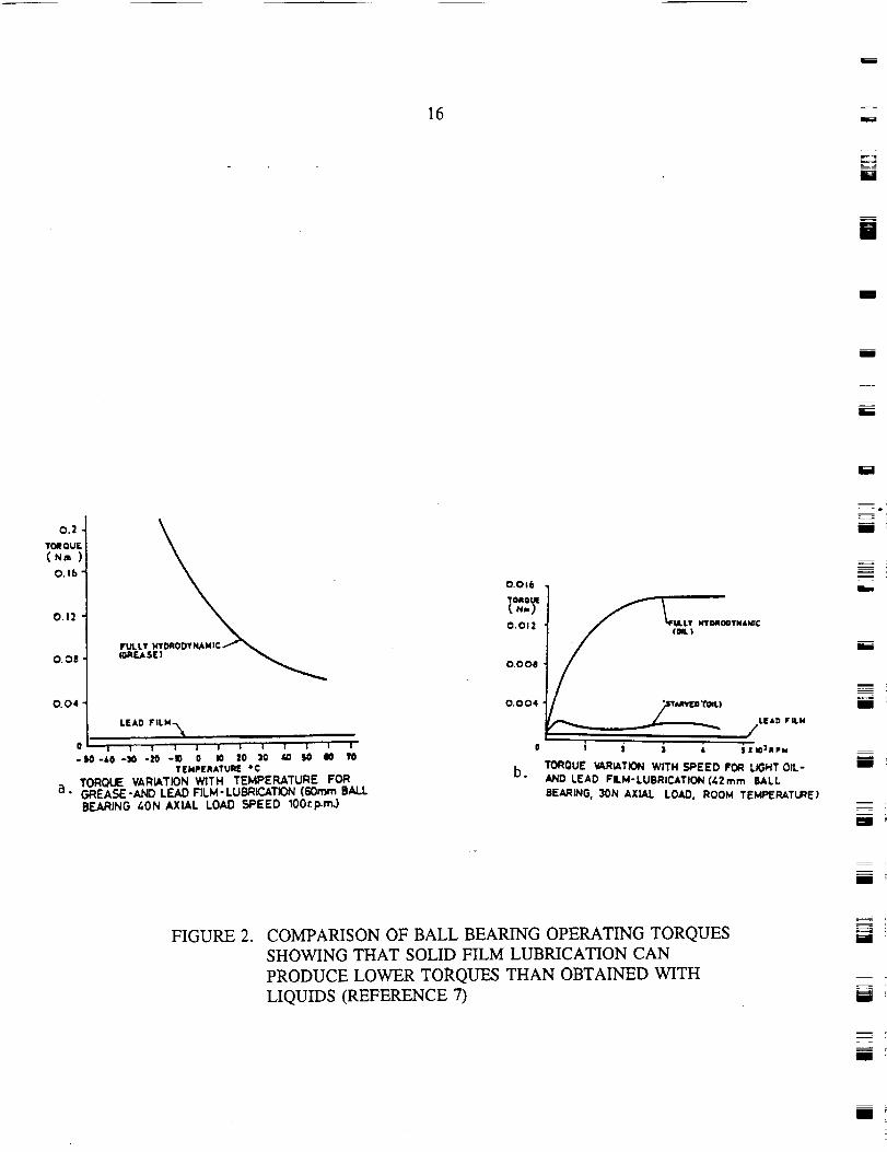
Friction in rolling contact can be lower with solid films than with grease
lubrication. Todd and Bentall (7) present data (Figure 2) that illustrate this effect.
Table 7 summarizes data for solid lubricated ball bearings (7_. In some ball bearings, it
is possible to extend the coating life by using transfer film technology (8'9). In this
technology the solid film is transferred from the bearing cage to the ball and races.
The cage in essence is then the lubricant supply. Transfer film technology represents a
good approach for extending the life of space bearings beyond that attained with solid
lubricant coatings.
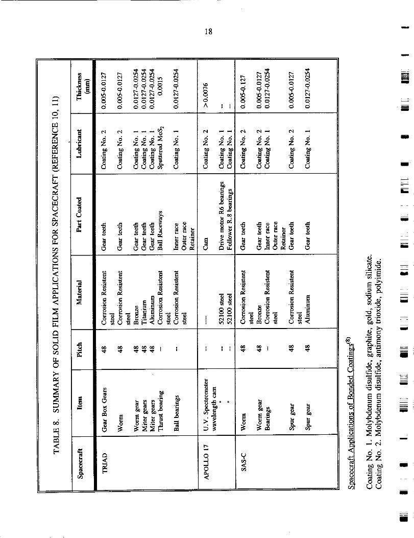
A summary of examples of successful applications of solid film lubricants
to cams, gears, and bearings in spacecraft (t°'11_ is given in Table 8.
s _77

14
--I
UTABLE 3. WEAR LIFE OF SOLID FILMS (REFERENCE 5)
Material
MoS 2
K Cycles980 N (500 min "1)
50
980 N (1000 min q)
<10
Graphite < 10 < 5
Sb(SbS4) ....
MoS 2 + Sb(SbS4) 140 40
Graphite + Sb(SbS4) 20 10
MoS 2 + Graphite 200 75
MoS 2 + Graphite + Sb(SbS4) 500 100
Bonded Solid Lubricant 200 50
mm
[]
M
l
I
I
mI
l
TABLE 4. STABLE FRICTION COEFFICIENT (REFERENCE 5)
Load
N
245
980
1470
Speedmin -I
Graphite
Lubricant
CSb-B MoS 2
500 none 0.14-0.15 0.03-0.05
500 none none 0.05
500 none none none
MSb-B
0.02-0.04
0.01-0.03
noneI
z
m
m
I
15
L -_.
[ i!
Li
L
TABLE 5. EXPERIMENTAL CONDITIONS FOR DATA
IN TABLES 3 AND 4 (REFERENCE 5)
outer diameter:
material:
hardness:
roughness of surface after
sandblasting:
Block
dimensions:
material:
hardness:
roughness of surface:
0.47 mm
100 CrMn6 steel
HRC 60
12 _m CLA
24x 15x6
90 MnCrV8 steel
HRC 54
1.6 _m CLA
3
Z = :
TABLE 6. WEAR TEST RESULTS FOR MoS 2 FILMS
(500 - 1000 nm THICK) FROM DIFFERENT
LABORATORIES (REFERENCE 6)
Wear Life, Thousands of Revolutions
Pin-On-Disk Dual-Rub-Shoe Thrust-Washer
201 19_ 600-700
--- 55 _ 800
156 60 b 300
45 35 K _ 900
L,d
Wested in air; hAir or vacuum; ¢Vacuum
?
16
i
m!s
BEE
i
i
0.2 "
TOR OUF.
(Nm
O.16
0.12
O. OI!
0.04
LEAD FILM-_
'''' '' ';0' ' ';0-S0 -&O -30 -20 -10 O 110 |0 _W SO liO
TEMPERATURE *C
TORQUE VARIATION WITH TEMPERATURE FORa. GREASE-AND LEAD FILM-LUBRICATION (60ram BALL
BEARING 40N AXIAL LOAD SPEED lOOrpm.)
O.Oe6
OltOUT
0.012
O.O011
0.004
LEAD FILM
X W31_PM
TOROUE VARIATION WITH SPEED FOR LIGHT OIL-
AND LEAD FILM-LUBRICATION (42ram BALL
BEARING, 30H AXIAL LOAD. ROOM TEMPERATURE_
_=mm
I
m
mm
umm
m
mm
FIGURE 2. COMPARISON OF BALL BEARING OPERATING TORQUESSHOWING THAT SOLID FILM LUBRICATION CANPRODUCE LOWER TORQUES THAN OBTAINED WITHLIQUIDS (REFERENCE 7)
i
i
R

L
t =:
_-i
17
¢,.1--a
L
i E ._
F
F_
F_
TABLE 7. TORQUE BEHAVIOR OF SOLID LUBRICATED BALL BEARINGS
(REFERENCE 7)
Method of
Lubrication
PTFE/MoS2/
glass fiber cage,
degreased racesand balls
MoS2-coated
raceways,
Phenolic cage
IP lead on
raceways, lead
bronze cage
Preload
fN)
40
100
100
Cumulative
time at
100 rpm
(rain)
0
30
60
0
5
15
30
60
74
5
15
35
60
240
Torque (N-m x 10 -4)
to oscillation
Average
(+)
21
25
57
34.5
31.5
42
45
39
Peak-Peak
76
98
147
148
156
246
282
168
failed by excess
torque
50 320
45 132
45 120
45 135
45 180
failed by excess
torque
Remarks
Progressive torqueincrease
Smooth start
} trace
} developing
} spikes
Spikes duringrun-in
} very smooth
} stable
} torque traces
i [::_
18 u
©
r.¢lZ©
.1
©
©
°_
o
m
0
6 dddN 6Z Z ZZZ N Z
o o ou u _66& u
e e eeeN
u _ _6 u_
°
A
I I I
t"q
_r_ cq
8_
r,.,.-
ddZZ
d dZ Z
o
.. .2
_ ! _-
o
O'_
o t19
m
,i..i °_,._
_E
o
66zZtall_¢- e-
•_.._ ',_,
mmm
U
BI
m
L_
m
m
I
I
I
U
I
I
i _
I
m
_t_
19
Liquid/Grease Lubrication
Advantages and Disadvantages
i L,.._
The primary advantage obtained with liquid lubricants is that bearing surfaces
separated by hydrodynamic films of liquid lubricants have virtually no wear and thereby
have the potential for indefinite lives. LiqUidiubricants provide the viscosity needed
for forming the hydrodynamic films, low shear strengths for low friction, cooling
capability in recirculating systems, and the abiiity to minimize wear in low-speed (non-
hydrodynamic) situations. Since no single lubricant can meet the often conflicting
requirements of various applications for liquids, hundreds of specialty lubricants have
been developed for aerospace applications _3). The primary disadvantages of liquid
lubricants are the need for containment, th-e propensity to creep, large changes in
viscosity with temperature, and loss by evaporation under vacuum conditions. The use
of thickeners to form greases provides a means of retaining the liquids in the needed
region, thereby addressing one of the primary disadvantages. Greases are widely used
for aerospace lubricants. The loss by evaporation greatly restricts the available liquids
for vacuum applications to the few chemical species having low vapor pressures. The
following sections consider the evaporation rates and the lubricating performance of
liquids (and greases based on these liquids) in bearing applications.
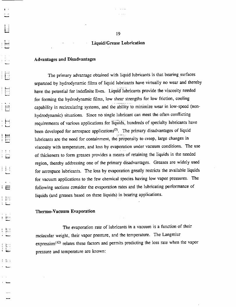
Thermo-Vacuum Evaporation
The evaporation rate of lubricants in a vacuum is a function of their
molecular weight, their vapor pressure, and the temperature. The Langmiur
expression o_) relates these factors and permits predicting the loss rate when the vapor
pressure and temperature are known:
20U
m
m
m
where,
P = vapor pressure (mm of Hg),
M = molecular weight, and
T = temperature of lubricant (°K).
The vapor pressure is strongly dependent on temperature, as shown for a perfluoro
ether in Figure 3(2). Perfluoro ethers are among the fluids having the lowest vapor
pressures and are leading candidates for satellite applications exposed to vacuum. At
the top of Figure 3 is the time predicted to evaporate a film 2.5 x 10.4 cm (100
microinches) thick in accordance with the Langmiur expression. With this strong
temperature dependence, two conclusions are drawn:
1. The temperature of lubricant films exposed to vacuum must be controlled to
retain the lubricant.
, Provisions must be made for the reapplication of lubricant if temperature
cannot be controlled to acceptable levels.
The chemical composition of a lubricant and its molecular weight are the
dominating factors in determining the resulting vapor pressures and loss rates. For
vacuum applications, silicones and perfluoro ethers have lower loss rates by 4 to 5
glO
Iil
= =
u
U
N
l
M
[]
m
mmm
[]
I
-.__=
M
!
B_
z
I

r ¸
21
LJ
19YR75D 21HR1 x 10-4 (_10-6) i
1 xl0 "5Aa:
O1 x10-6
E
0.
UJ" 1 xl0 "7
cOcOuJ 1 x 10⁻⁸ (_10-10)
o..n,.Oa. 1 x 10⁻⁹
>
1 x 10"10
1 x 10-11 (-10-13)293 373
TEMPERATURE, ° K
0.025 HR
473
=- ._
FIGURE 3. DEPENDENCE OF VAPOR PRESSURE ON TEMPERATURE
FOR A PERFLUORO ETHER LUBRICANT (REFERENCE 2)
L_5

22
orders of magnitude compared with mineral oils (hydrocarbons) or diesters 03). On the
basis of loss rates by evaporation, the selection of lubricants is limited to the perfluoro
ethers or silicones -- both from the standpoint of retaining the lubricant on the beating
surfaces where they are needed and of preventing contamination of optical systems by
condensation of the evaporated lubricant. As discussed in the next section, the wear
performance of the various lubricants combined with the creep behavior of silicones
further limits the practical choice to the perfluoro ether fluids.
Friction and Wear Performance
i
tl
l
l
Among the many properties provided by liquid lubricants for bearing
applications, the ability to generate hydrodynamic films to separate the surfaces in
relative motion and the ability to maintain low wear rates if the operating conditions
prevent film formation are two of the most important properties. Film formation
capabilities are largely determined by the viscosity, which is generally high in fluids
selected to have low evaporation rates. Therefore, the ability to lubricate under very
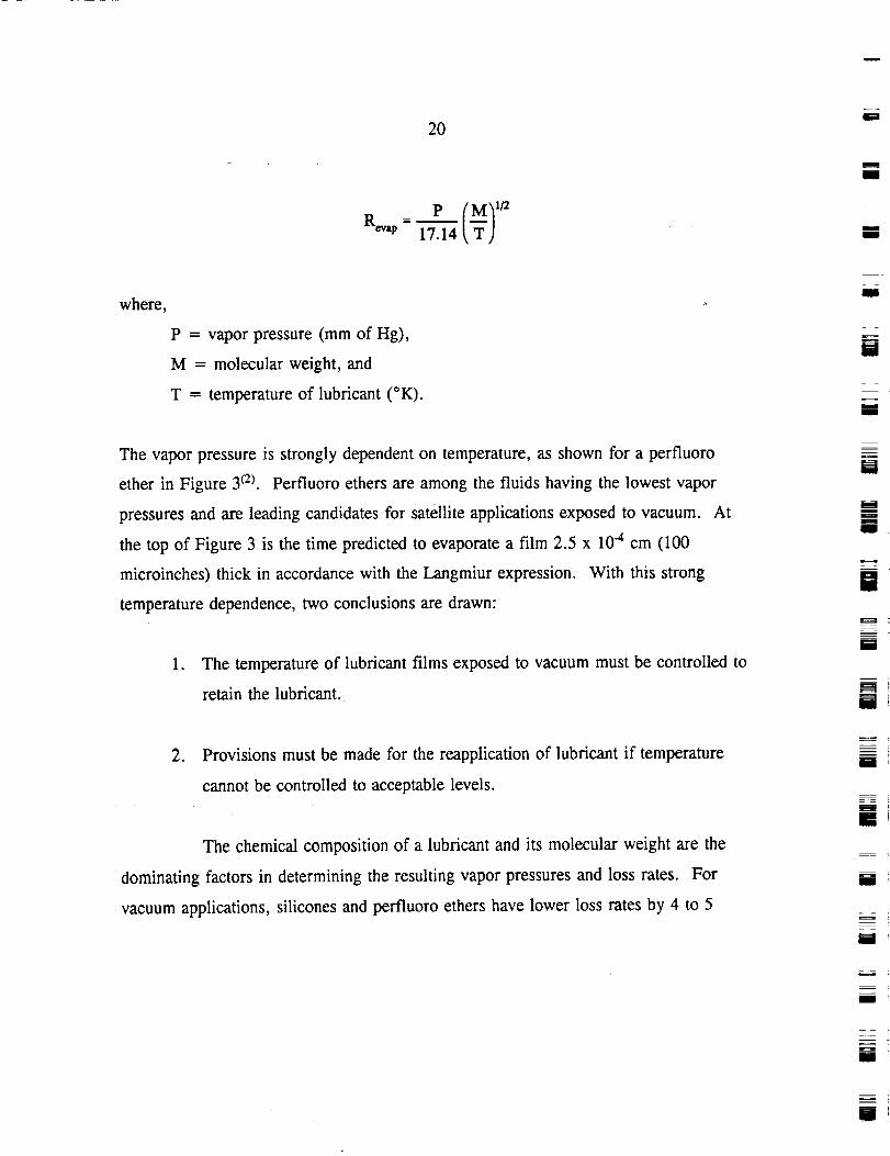
thin film (boundary) conditions is the performance property of interest.
Table 9 presents a summary of comparison data obtained from LFW-1 ring-
on-block tests with various lubricants and 440C rings and blocks (14). Of particular
interest is the performance of the perfluoro ether (Krytox 143AB oil and Krytox
240AB grease) relative to the silicones, mineral oil, and diesters. No instances of
galling were observed with the perfluoro ethers, but several instances of galling were
encountered with the silicones, diesters, and mineral oils. Although the lowest wear
was measured with the FS1265 silicones, its viscosity was also the highest, which may
have influenced the results. The wear with the perfluoro ether was less than that
measured with the mineral oils and was considered acceptable since no instances of
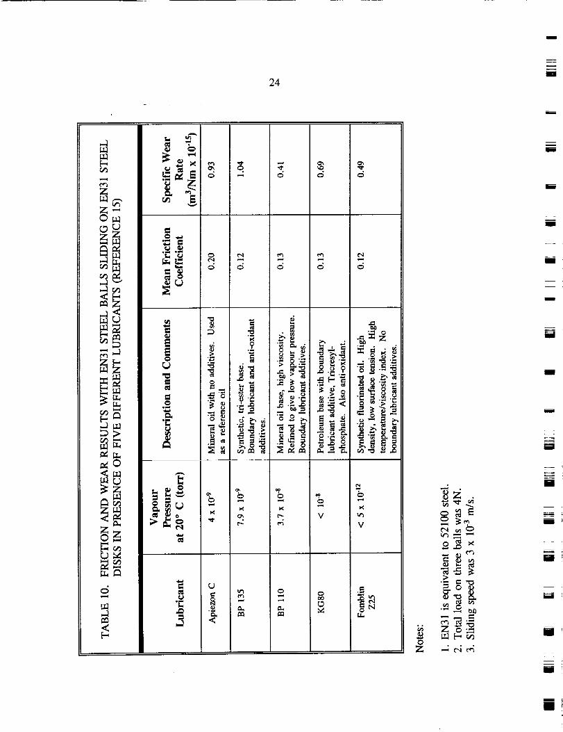
galling occurred. As shown in Table 10, similar results were obtained in slow-speed
sliding tests using a ball-on-flat geometry (15). The perfluoro ether (Fomblin Z25) had a
friction coefficient tying the lowest of the five and a specific wear rate only slightly
m
m
u
l
w
U
i
I
I
im!
1m
i:
LJ
= :
r_
E_
: LL_
!_ r_!
]]
©,-1
©
0
0,-1
©_z
23
I.I
A A A A A
O
Zo
• _ _ _
_. _ ,i_ ..
tm ._
",_ OO
24I
i
u_
_J9
Z'-
"" ..1
L)
r..)M
°_ _
_ ° _
0_
o
_ ._-._ - _
0
_
0
v
o
v
Z
z
i
i
I
i
i
=i
i
i
i
=_ =
I
E
fw
25
higher than the lowest recorded (a mineral oil with boundary lubricant additives).
Based on friction and wear results such as these, a much lower propensity to creep, and
satisfactory flight experience, the perfluoro ethers have displaced the silicones in
spacecraft applications 06).
Besides the Krytox and Fomblin fluids, the Bray Oil Co. has produced a series
of lubricants by further distilling and refining the Fomblin fluid base stock to produce
Bray 815Z oil and 3L38RP grease, which have had flight experience in spacecraft
mechanisms. The products are now available through the Bray Products Division of
Burmah-Castrol, Inc. Braycote 601 is the new designation for the 3L38RP grease.
w
!
Z -T _
26
IDENTIFICATION OF SPECIFIC TRIBOLOGICAL COMPONENTS
SRS Technologies, as a major subcontractor on the Space Station Long Term
Lubrication Analysis program, undertook the effort to identify the specific wear/bearing
points in the overall Space Station and obtain design information to permit a review
from a tribology standpoint. From the relatively broad range of assemblies,
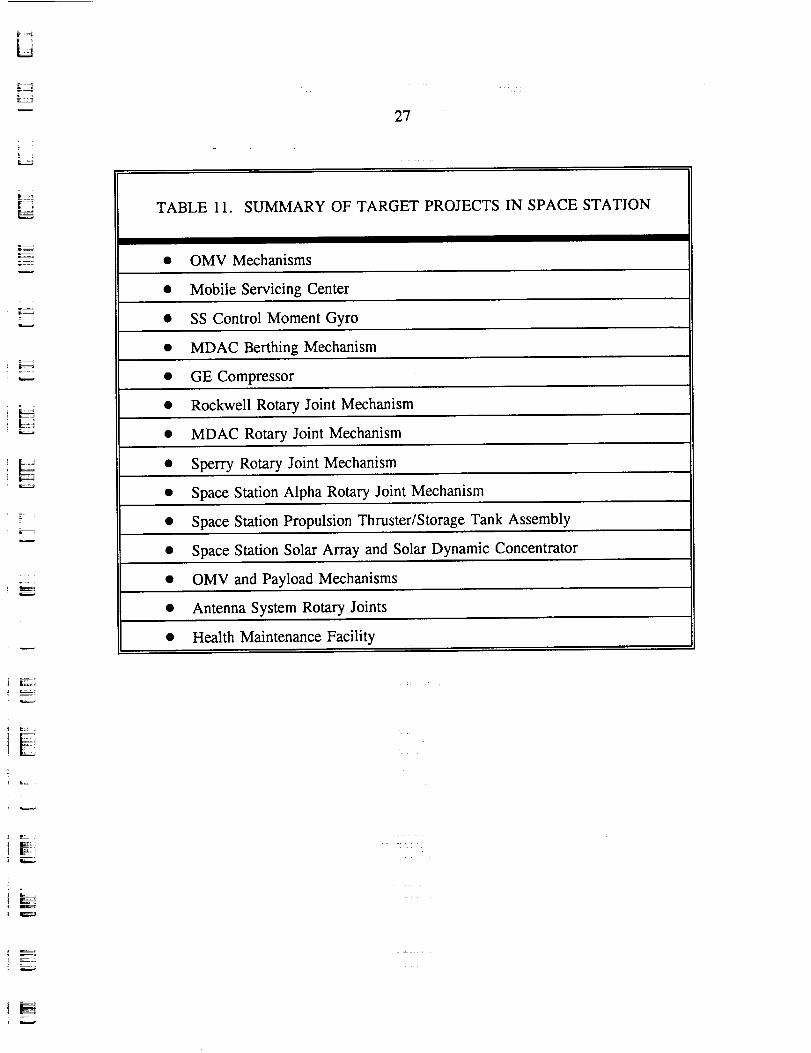
components, and mechanisms, a group of 14 target projects were identified as being
likely to contain wear points of interest. A listing of these 14 target projects is
presented in Table 11. A discussion of the efforts to attain detailed design data are
presented on pages 22 through 29 of the SRS Technologies report in Appendix A.
Specific tribological components identified in the survey are summarized in Table 2,
pages 35 through 39 of the SRS Technologies report. While 72 specific components
were identified, insufficient details were available at the time the survey was done to
permit a review of their likely performance.
While sufficient design details were not forthcoming, the survey clearly
identified the large alpha and beta joints to be critical components without comparable
prior flight performance. Therefore, the bearings comprising these joints are worthy of
more detailed examination. The design of the hundreds of other tribological contacts
will range in difficulty from relatively routine (conservative designs with flight history)
to the complexity and size of the alpha and beta joints. To assist the process, the
preparation of a lubrication guide for use by the designers as a practical guide for
choosing lubricants suitable for various types of applications appeared to be a useful
and attainable goal. Therefore, the remainder of the program was structured to be:
Phase II.
Phase III.
Evaluation of Lubrication of the alpha and beta joints
The preparation of a lubricant guide for NASA and/or
contractors to use in selecting and evaluating component
lubrication techniques.
m
m
U
B
i
z
m
-- =
U
[]
m
m
m
m
J
m
I
m
i
R
=
27
TABLE 11. SUMMARY OF TARGET PROJECTS IN SPACE STATION
• OMV Mechanisms
• Mobile Servicing Center
• SS Control Moment Gyro
• MDAC Berthing Mechanism
• GE Compressor
• Rockwell Rotary Joint Mechanism
• MDAC Rotary Joint Mechanism
• Sperry Rotary Joint Mechanism
• Space Station Alpha Rotary Joint Mechanism
• Space Station Propulsion Thruster/Storage Tank Assembly
• Space Station Solar Array and Solar Dynamic Concentrator
• OMV and Payload Mechanisms
• Antenna System Rotary Joints
• Health Maintenance Facility
E_
28
REFERENCES
.
o
.
.
.
.
,
Leger, L.J., Visentine, J.T., and Schliesing, J.A., "A Consideration of Atomic
Oxygen Interactions with Space Station", AIAA 23rd Aerospace Sciences Meeting,
January 14-17, 1985, AIAA Paper 85-0476.
Leger, L.J., and Dufrane, K.F., "Space Station Lubrication Considerations",
Proceedings 21 st Aerospace Mechanism Symposium (NASA Conference
Publication No. 2470), April 29-May 1, 1987, pp. 285-294.
McMurtrey, E.L., "Lubrication Handbook for the Space Industry", NASA
Technical Memorandum NASA TM-86556, December, 1985.
Martin, P., Jr., "A Survey of Solid Lubricant Technology", U.S. Army Weapons
Command, AD741764, March, 1972.
Bartz, W.J., Holinski, R., and Xu, J., "Wear Life and Frictional Behavior of
Bonded Solid Lubricants", Lubrication Engineering, December 1986, pp. 762-769.
Fleischauer, P.D., Hilton, M.R., and Bauer, R., "Effects of Microstructure and
Adhesion on Performance of Sputter-Deposited MoS 2 Solid Lubricant Coatings;
conducted for Wright Research and Development Center, WPAFB, Contract No.F04701-88-C-0089, Aerospace Report No. TOR-0090(5064)-2, January 15, 1990.
Todd, M.J., and Bentall, R.H., "lead Film Lubrication in Vacuum", European
Space Tribology Lab., Risley, U.K. and European Space Tribology Center,
Noordwijk, Holland.
8. Scott D., and Blackwell, J., "Sacrificial Cage Materials for the In-Situ Lubrication
of Rolling Bearings", paper presented at the European Space Tribology
Symposium, Frascati, 9-11 April 1975.
9. Kannel, J.W., Gleeson, J.B., Dufrane, K.F., "Battelle Self Lubricating Insert
Configuration (BASIC) Retainer", Earth-to-Orbit Conference, May, 1990,
Huntsville, AL.
10. Lansdown, A.R., "Low Temperature Lubrication", Swansea Tribology Center,
prepared for European Space Agency, 27 April 1978.
Matley, R.A., "Lubrication of Space Systems", Lub. Eng. 34 (2), 79, 1978.
Dushman, S., Scientific Foundations of Vacuum Technique, Special Edition, John
Wiley and Sons, Inc., New York, NY, 1962, p. 18.
I
b
m
I
m
m
m
il
U
i
M i
!
==--i JB
M
I '
ii
[]
!imw
mi
i

L !
_.+:-
13.
29
Hamilton, D.B., and Ogden, J.S., "The Evaporation of Various Lubricant Fluids in
Vacuum", (ASLE Preprint, 1972).
14. Babecki, A.J., Grenier, W.G., and Haehner, C_L., "Liquid and Grease Lubricants
for Space Applications", Goddard Space Flight Center Materials Technology
Report MTR No. 313-003, December 1976, N81-71132.
15. Thomas, A., "Boundary Lubrication of Steel by Various Oils of Low Vapor
Pressure", Proceedings of the Second Space Tribology Workshop, European Space
Agency, 1980, Risley, U.K., pp. 65-68.
16. Briscoe, H.M., "Some Considerations onLubricants for use in Spacecraft",
Spacecraft Materials in Space Environment, European Space Agency ESA SP-178,
1982, pp. 27-34.
, r
l L:.
=
|
!
:: ::::::: .
30
BIBLIOGRAPHY
Liquid Lubricants
Babecki, A.J., Grenier, W.G., Haehner, C.L., "An Evaluation of Liquid and Grease
Lubricants for Spacecraft Applications", Materials Technology Report, Dec 1976,
Materials Control and Applications Branch, Goddard Flight Center.
Hafner, E.R., "Proper Lubrication - The Key to Better Bearing Life (part 3), Extreme
Operating Conditions", Mechanical Engineering, Vol. 99 (no. 12), pages 35-40, Dec.1977.
Paris, J., Szydlo, S.T., "Lubricating Miniature Bearings", Machine Design, July 1989.
Progress Report, "The Performance of Fomblin Z25 Oil in Ball Bearing Operating in
Vacuum", European Space Tribology Lab., Risley, U.K., July 1983.
Stevens, K.T., "The Torque Behavior of Grease-Lubricated Angular Contact Bearings
Operating at Low Speeds", European Space Tribology Lab., Risley, U.K..
Thomas, A., "Boundary Lubrication of Steel by Various Oils of Low Vapor Pressure",
Proceedings of Second Space Tribology Workshop, European Space Tribology Lab.,
Risley, U.K., Dec. 1980.
Zaretsky, E.V., Schuller, F.T., Coe, H.H., "Lubrication and Performance of High-
Speed Rolling-Element Bearings", prepared for the 1985 Annual Meeting of the
American Society of Lubrication Engineers, Las Vegas, Nevada, 6-9 May 1985.
Spacecraft Lubricants
Babecki, A.J., Grenier, W.G., Haehner, C.L., "An Evaluation of Liquid and Grease
Lubricants for Spacecraft Applications", Materials Technology Report, Dec. 1976,
Materials Control and Application Branch, Goddard Flight Center.
Baxter, B.H., "The Use of MoS 2 Loaded Greases in Antenna Despin Mechanisms
under Simulated Space Conditions", Proceedings of European Space Agency
Symposium on Spacecraft Materials, 2-5 Oct. 1979.
m
= =
M
I
I
Ill
I
m
mg
m
S
H
ll
ul
M
Z
III
I
7
m
I
im
rk.....
H
L
=:: =
w
__=
_L
31
Benzing, R.J., Strang, J.R., Capt., USAF, "Failure Mode Analysis of Lubricated
Satellite Components", Nonmetallic Matei'ialsDiv., Lubricants and Tribology Branch,
AFML/MBT, Wright-Patterson AFB, OH 45433, July 1973.
Briscoe, H.M., "Some Considerations on Lubricants for Use in Spacecraft", European
Space Agency, European Space Research and Technology Center, Noordwijk,
Netherlands.
Briscoe, H.M., Todd, M.J., "Considerations on Lubrication of Spacecraft
Mechanisms", European Space Agency, European Space Research and Technology
Center, Noordwijk, Netherlands, The 17th Aerospace Mechanisms Symposium, pages19-38.
Brouwer, G.F., "Lubrication of a Stainless Steel Actuating Cable", Proceedings of
Second Space Tribology Workshop, European Space Tribology Lab., Risley, U.K.,Dec. 1980.
Guertin, L.J., "Lubrication on the Space Shuttle Orbiter", 15th National SAMPE
Technical Conference, Cincinnati, OH, 4'6 OCt. 1983.
Guidelines for Space Materials Selection, European Space Research and Technology
Center, Product Assurance Division, Noordwijk, The Netherlands, July 1976.
Hadley, H., "Mechanisms of U.K. Radiometers Flown on Nimbus 5 and 6 with
Particular Reference to Bearings, Pivots and Lubrication", Proceedings of the 14th
Aerospace Mechanisms Symposium, pages 101-i 10.
Investigation of Torque Anomaly in Oscillating PDM Bearings, Contract Report,
European Space Agency, Risley, U.K., May 1981.
Jantzen, Dr. E., "A Dry Lubrication System for Space-Proofed Bearings", paper
presented at the European Space Tribology Symposium, Frascati, 9-11 April 1975.
Lansdown, A.R., "Low Temperature Lubrication", Swansea Tribology Center,
prepared for European Space Agency, 27 April 1978.
Leger, L.J., Dufrane, K., "Space Station Lubrication Considerations", Proceedings
21st Aerospace Mechanism Symposium (NASA Conference Publication No. 2470),
April 29-May 1, 1987, pp. 285-294.
Loewenthal, S.H., Schuller, F.T., "Feasibility Study of a Discrete Bering/Roller Drive
Rotary Joint for the Space Station", NASA Technical Memorandum 88800, Lewis
Research Center, Cleveland, OH., July 1986.
L
32
McMurtrey, E.L., "Lubrication Handbook for the Space Industry", NASA Technical
Memorandum, TM-86556, May, 1983.
MoS 2 Helps Prevent "Tennis Elbow" in Space Shuttle Manipulator Arm, Amax, Vol
XXVI (no. 1), May 1984, Climax Molybdenum Co., New York.
Spacecraft Materials in a Space Environment, European Space Agency, Paris, France,
July 1982.
Stevens, K.T., "Some New Observations on Wear in Oil-Lubricated Satellite Bali
Bearings", Proceedings of Second Space Tribology Workshop, European Space
Tribology Lab., Risley, U.K., Dec. 1980.
Todd, M.J., "Solid Lubrication of Ball Beatings for Spacecraft Mechanisms",
Tribology International, Vol. 15 (no. 6), pages 331-337, Dec. 1982.
Ward, W.E., "Evaluation of a 90-mm Bore Bearing Operating in a Simulated Space
Environment", Air Force Wright Aeronautical Lab., Wright Patterson AFB, OH.,
45433, Presented at the 38th Annual Meeting in Houston Texas, 24-28 April 1983.
Ward, W.E., "Evaluation of 100-ram Bore Bearings After Accelerated Testing in a
Simulated Space Environment", Technical Report, July 1979, Nonmetallic Div., Fluids,Lubricants and Elastomers Branch, Air Force Materials Lab., Wright-Patterson AFB,
OH., 45433.
Solid Lubricants
Bartz, W.J., Holinski, R., Xu, J., "Wear Life and Frictional Behavior of Bonded Solid
Lubricants", Lubrication Engineering, Vol. 42 (no. 12), pages 762-770, Dec. 1986.
Cerini, J.P., Devine, G.M., "Development of Improved High Temperature Solid
Lubricant Concepts, phase I", General Technology, 2560 Prescott Road, Havertown,
PA 19083-1301, May 1990.
Todd, M.J., Bentall, R.H., "Lead Film Lubrication in Vacuum", European Space
Tribology Lab., Risley, U.K. and European Space Tribology Center, Noordwijk,
Holland.
Citations From the Engineering Index Database, "Solid Lubricants: Graphite,
Polymers, Fluorides, and General Studies (Feb. 82 - Nov. 85)", Battelle Reports
Library, 505 King Ave., Columbus, OH 43201.
I
J
__.._
=
N
INU
I!
Him
mm
g
!-_ ..... Citations From the Engineering index Database, "Solid Lubricants:m
Graphite,
Polymers," Fluorides, and General Studies (Feb. 82 - Nov. 84)", Battelle Reports
Library, 505 King Avel, Columbus, OH 43201.
Didziulisl S.V., Fleischauer, P.D., "EffectYs of Chemical Treatments on SiC surface
composition and Subsequent MoS a Film Growth", The Aerospace Corp., Chemistry and
PhysicS_Labo_o_, Prepar_ for Defense-Advanced Research Projects Agency,
!_-- :.... Arlington VA 22209.
!i_ _ Fleischauer, P.D., Lincel]LR_,Bertrandl _i-,_,'"Electronic Structure and Lubrication
Properties of MoS2: A Qualitative Molecular Orbital Approach", The Aerospace
, _ C0_.; Chemist_ _d Physics Lab0ratory, Prepared for Space Systems Div. Air Force
_ Systems Command, Los Angeles Air Force Base, L.A., CA 90009-2960.
!B
iB= -- =
= z =
Fleischauer, P.D., Hilton, M.R., Bauer, R., "Effects of Microstructure and Adhesion
on Performance of Sputter-Deposited MoS 2 Solid Lubricant Coatings", Chemistry and
Physics Lab., The AeroSpace Corp., prepared for Wright Research and Development
Center, Wright-Patterson AFB, 15 Jan. 1990.
Fleischauer, P.D., Hilton, M.R., Bauer, R., "Effects of Microstructure and Adhesion
on Performance of Sputter-Deposited MoS 2 Solid Lubricant Coatings", The Aerospace
Corp., Chemist_ _d Physics Laboratory, Prepared for Wright Research and
Development Center, Wright Patterson Air Force Base, OH 45433.
Gardos, M.N., "Seif-Lubricating Composites for Extreme Environment Applications",
Tribology International, Vol. 15 (no. 5), pages 273-283, Oct. 1982.
Klenke, C.J., "Tribological Performance of MoS 2 - B203 Compacts", Tribology
International, Vol. 23 (no. 1), pages 23-26, Feb. 1990.
Lansdown, A,R., "Molybdenum Disulfide Lubrication", A Continuation Survey 1979-
80, Sw_sea Tribology Center, _U.K., European Space Agency Contract no 2261/74........... : :_?: .........
Martin, P., Jr., "A Survey of Solid Lubricant Technology", Technical Report,
Research, Development and Engineering Directorate, U.S. Army Weapons Command,March 1972.
Scott, D. and, Black-well, J., "Sacrificial Cage Materials for the In-Situ Lubrication of
Rolling Bearings", papei: presented at the European Space Tribology Symposium,Frascati, 9-11 April 1975.
Spalvins, T., "Sputtering and Ion Plating for Aerospace Applications", NASA
Technical Memor_dUmgI726, prepared for the National Conference of the American
Electroplaters' Society, Boston, MA, June 28 - July 2, 1981.
i
mm
34
Thomas, A., Todd, M.J., Garnham, A.L., "Current Status of I_gad Lubrication of Ball
Bearings", Proceedings of the Second Space Tribology Workshop, ESTL, Risley, U.K.,
15-17 October 1980.
Todd, M.J., "A Method for the Calculation of Torque in Dry-Lubricated Ball Bearings
Including the Influence of Temperature and Fit", Proceedings of Second Space
Tribology Workshop, European Space Tribology Lab., Risley, U.K., 15-17 Oct. 1980.
Todd, M.J., "Solid Lubrication of Ball Bearings for Spacecraft Mechanisms",
Tribology International, Vol. 15 (no. 6), pages 31-337, Dec. 1982.
White, C., Todd, M.J., "Torque Properties of Oscillating Dry-Lubricated Ball Bearings
in Vacuum", European Space Tribology Lab., Risley, U.K., Sept. 1983.
Slip Rings
Anderson, J.C., Roberts, E.W., "Satellite Slip Ring Performance - A Summary of
ESTL Work 1974-81", European Space Tribology Lab., Risley, U.K., Aug 1982.
Anderson, J.C., "The Wear and Electrical Characteristics of Some Dry Lubricated Slip
Ring/Brush Contacts", Proceedings of Second Space Tribology Workshop, European
Space Tribology Lab., Risley, U.K., 15-17 Oct 1980.
Roberts, E.W., "A Review of Sliding Electrical Contacts for Space Application",
European Space Tribology Lab., Risley, U.K., Oct 1981.
w
U
I
m
I
m
D
Gears
ESTL Progress Report for 1982, European Space Tribology Lab., Risley, U.K., March
1984.
First European Space Mechanisms and Tribology Symposium, Proceedings of a
Symposium held at Neuchatel, Switzerland, 12-14 Oct 1983.
Stevens, K.T., "The Tribology of Gears for Satellite Applications", Proceedings of the
First European Space Mechanisms and Tribology Symposium, Neuchatel, Switzerland,
12-14 Oct 1983.
I
b
L _ .
L2
i g==---.
J
L1
35
Stevens, K.T.,-"The Wear of Small Plyacetal and Polyimide Gears in Vacuum",
European Space Tribology Lab., Risley, U.K..
Transport Studies
Ahlborn, G.H., "Lubricant Barrier Film Contaminated Ball Bearings - A Bearing Life
Threat?", Lubrication Engineering, Vol. 35 (no, 12), 12 Dec 1979, pages 677-686.
Fleischauer, P.D., Marten, H.D., "Surface Creep of Mineral Oil on Inner Ring of
Momentum Wheel Beating", presented at the 40th Annual Meeting in Las Vegas,
Nevada, 6-9 May 1985, Lubrication Engineering, Vol. 42 (no. 5), pages 300-304.
Fote, A.A., Slade, R.A., Feuerstein, S., "Barriers to the Surface Transport of Oil",
Interim Report prepared for Space and Missiie Systems Org., 18 Feb 1977, Air Force
Systems Command, Los Angeles Air Force Station.
Fore, A.A., Slade, R.A., Feuerstein, S., "The Prevention of Lubricant Migration in
Spacecraft", Wear, Vol. 51 (no. 1), pages 67-75, 1 Nov 1978.
Fote, A.A., Slade, R.A., Feuerstein, S., "Behavior of Thin Oil Films in the Presence
of Porous Lubricant Reservoirs", Wear, Vol. 46 (no. 2), pages 377-385, 2 Feb 1978.
Hamilton, D.B., Ogden, J.S., "The Evaporation of Various Lubricant Fluids in
Vacuum", presented as an American Society of Lubrication Engineers paper at theASME/ASLE International Lubrication Conference, New York City, 9-12 Oct i972.
w
Miscellaneous Articles
Anacapri, Italy, "Europe May Barter for External Payloads on NASA/International
Space Station", Aviation Week and Space TeChnology, 10 July 1989, pages 29-30.
Brahney, J.H., "Large Payload Launch Vehicles Examined", Aerospace Engineering,
April 1985, pages 28-33.
Brahney, J.H., "Space Station: an investment in scientific research", Aerospace
Engineering, Aug. 1985, pages 27-31.
n
36
Brahney, J.H.,-"Space Station's Biggest Challenge: servicing satellites in orbit",
Aerospace Engineering, March 1985, pages 9-13.
Buckley, D.H., "Tribological Systems as Applied to Aircraft Engines", prepared for
the 60th AGARD Structure and Materials Panel Meeting, San Antonio, TX, 21-26
April 1985.
Davis, K., Keller, M., Martin, R., "Accelerated Life Prediction Techniques", Final
Report for Period 31 July 1978 - 31 May 1981, Materials Lab., Air Force Wright
Aeronautical Lab., Wright-Patterson AFB, OH, 45433.
Feuerstein, S., Forster, A.S., "A Concept of Despin Mechanical Assembly Life
Testing Involving Total Characterization", Aerospace Corp., prepared for Space and
Missile Systems Org., Los Angeles Air Force Station, L.A., CA 90045, 29 July 1975.
Holt, D.J., "Will Solar Dynamic Power Be Used for the Space Station?", Aerospace
Engineering, Sept. 1985, pages 49-55.
Lauer, J.L., "Structure of Solid Surfaces in Wear Situation", Final Report to Air Force
Office of Scientific Research, 17 Oct. 1984.
McCarty, L.H., "Space Station Rotary Joint Eliminates Stiffness Dead Band", Design
News, 15 Feb. 1988, pages 160-161.
w
i
I
m
m
!
[]
m
m
I
ili
[][]
[]
I
m_
m
B
tmI
i
w
37
i_i iii
E
_L!
APPENDIX A
SRS TECHNOLOGIES SUBCONTRACTOR REPORT
1 F
i
m
i
|
m
i
m
m
m
m
i
m
i
m
U
i
i
i
i
t= i
SRS/STG TR90-84
Space StationLong Term Lubrication Study
Final Report
June, 1990
; =
- _
= = ,
BY
EDWARD. E. MONTGOMERY
SRS Purchase Contract Number: G-9038
NASA Contract: NAS8-36655
iK
APPROVED BY: /_" 'Sq. _'_'-'-*'--Z_(J U
Jay H. Laue
Director, Aerospace Systems
APPROVED BY: C'l_,_ _,
c. w. Mea__General Manager, Systems Technology Group
! :
L= _
Foreword
This document was prepared by SRS Technologies under subcontract to
Battelle Columbus Laboratories for work relating to the "Space Station Long Term
Lubrication Study" for the Materials and Processes Laboratory at NASA's George C.
Marshall Space Flight Center. The work was performed under the supervision of
Mr. Keith Dufrane, the Battelle project manager and the NASA COTR, Mr. Fred
Dolan. It presents a comprehensive final reporting of the Phase I activities of this
project. The study was performed by SRS during the period from August, 1985 to
May, 1990. The SRS contract manager is Jay H. Laue of SRS Technologies' Systems
Technology Group, Aerospace Systems Directorate, in Huntsville, Alabama. The
SRS project leader is Edward E. Montgomery. Other significant contributors at SRS
included:
James C. Pearson, Jr.
Rod Myers
Anthony Stone
Cynthia Koontz
m
m
H
i
iI
zzm
i
m
u
m
I
Zi
zm ;
L_
I
!
m
i
I
u
D
mint
iii
ui
L..--
L
SECTION
TABLE OF CONTENTS
PAGE
rForeword ......................................................... ii
L
1.0 INTRODUCTION ................................................. 1
[[,_ 1.1
i_ 1.2
1.3
Background ................................................. 1
Objectives/Approach ......................................... 2
Project Schedule .............................................. 5
i L"
2.0 TECHNICAL ACCOMPLISHMENTS ................................ 11
2.1
2.2
! _'-_ 2.3
i L'___ 2.4
'_° 2.5
;- -_'_ 3.0
4.0=
Development of Space Station Work Breakdown Structure ...... 12
Environment Identification .................................. 18
Identification of Wear Points .................................. 22
Operating Requirements and Characteristics ................... 30
Tribology Matrix/Data Tape ................................... 32
CONCLUSIONS ................................................... 34
REFERENCES ..................................................... 40
Appendix A. Survey Forms ........................................ A-1
-¢i i
I _
l _7=i
iii
_
HaII
mira
mi
mi
m
_L_Im
iim
HI
m
[]
I
iiiim
Hi
in
_m
mIU
i
MI
I sIlUl
r •
i i i
i kJ
i L:-:_
i i-!
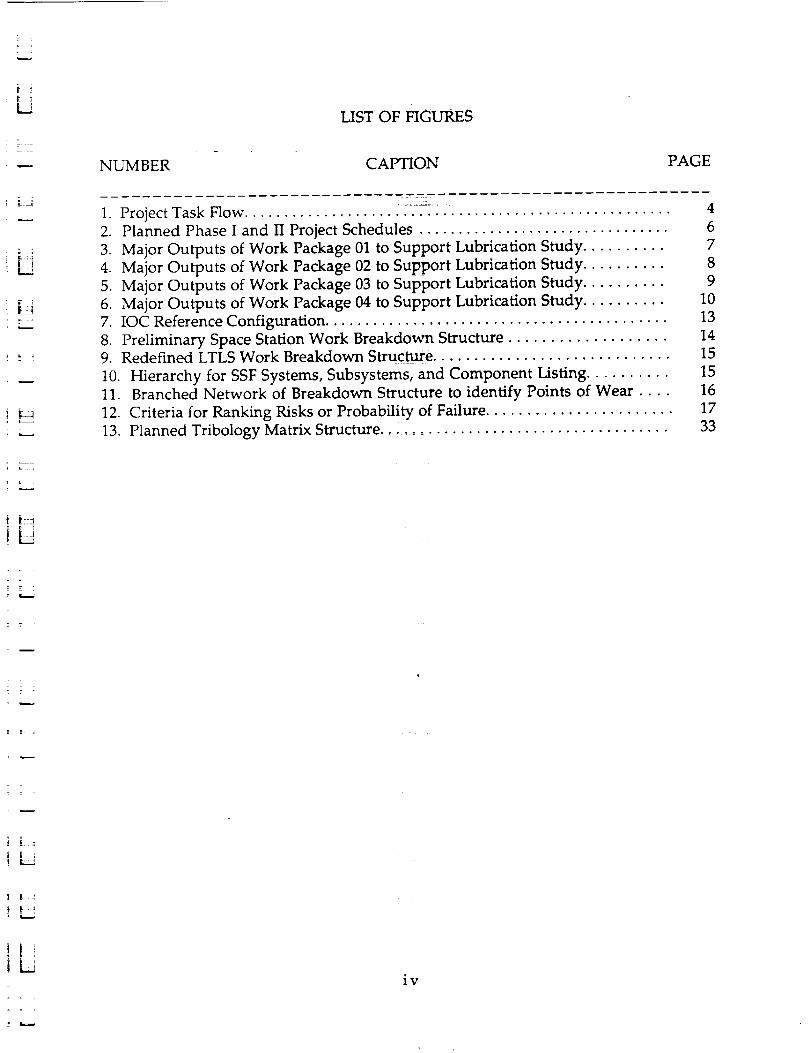
LIST OF FIGU'RES
NUMBER CAPTION
1. Project Task Flow ......................................................
2. Planned Phase I and II Project Schedules ................................
3. Major Outputs of Work Package 01 to Support Lubrication Study ..........
4. Major Outputs of Work Package 02 to Support Lubrication Study ..........
5. Major Outputs of Work Package 03 to Support Lubrication Study ..........
6. Major Outputs of Work Package 04 to Support Lubrication Study ..........
7. IOC Reference Configuration ...........................................
8. Preliminary Space Station Work Breakdown Structure ...................9. Redefined LTLS Work Breakdown Structure .............................
10. Hierarchy for SSF Systems, Subsystems, and Component Listing ..........11. Branched Network of Breakdown Structure to identify Points of Wear ....
12. Criteria for Ranking Risks or Probability of Failure .......................
13. Planned Tribology Matrix Structure... .................................
PAGE
4
6
7
8
9
10
13
14
15
15
16
17
33
J i
iv

LIST OF TABLES
NUMBER CAPTION PAGE
1. Representat_vebutgassing Data for Typical G_eases and Lul_ricants ......... 31
2. Preliminary Tribology Matrix 35
V
u
i
h
l
m
D
m
I
mI
mm
M_
m :
i .[
i
- i
Ii iir
Lii=
ii:L
] [±! -
= 2 =
= =
1.0 INTRODUCTION
7
Under subcontract to Battelle Columbus Laboratories (SRS purchase contract
G-9038) SRS performed selected activities in support of the "Space Station Long
Term Lubrication Study" (NAS8-36655), a contract effort with the Materials and
Processes Laboratory at MSFC/NASA. Mr. Fred Dolan is the NASA COTR, Mr.
Keith Dufrane is the BCL Project Leader, and Mr. Edward Montgomery is the SRS
Project Leader.
The Space Station Long Term Lubrication Study (LTLS) is part of the
Advanced Development Program (ADP) within the Space Station Program. In fiscal
Year 1985, the ADP was initiated to accelerate the development of a series of new
technologies. Its objectives were to enhance the performance of the Space Station,
reduce the life cycle cost during the operations phase, and reduce the risk that might
be encountered with new technologies:during the development phase.
1.1 Background
Work on the contract began on August 1, 1985. The project was scheduled to
be conducted over a 3-year time frame in-two phases. Phase I was a preliminary
analysis conducted in parallel with the preliminary design phases of the Space
Station program. Phase II was to be a more detailed analysis conducted during Phase
C/D when the design became more established. Phase I was to conclude 20 months
into the study (April 1987) and be based primarily on design data packages planned
to be released along with the Space Station Phase B SDR in September 1986.
However, the Space Station program schedule began to slip significantly. In
addition, major configuration changes continued to occur. As a result, the design
information was not maturing to a level sufficient to support the kinds of analyses
planned in the LTLS. An interim approach was taken in which the LTLS utilized
preliminary design data resulting from other ADP programs in lieu of mainstream
SSF design review packages (which were not available). The problem became
evident as early as October 1986 when it was first addressed in monthly progress
reports to the government. In April, 1987, at the originally planned date for
conclusion of the phase I activities, effort was suspended on the study to allow the
Space Station program schedule to catch up. Unfortunately, further SSF slippages
and major redesign efforts continued to keep the Long Term Lubrication Study
dormant through the original LTLS contract end date in August, 1988.

In October, 1988, an SRS representative attended a Space Station Space
Environmental Effects Data Exchange meeting at MSFC which included a
lubrication concerns topic on the agenda. Otherwise, no effort was expended on the
contract by SRS after April, 1987 until April, 1990. At that time, NASA extended the
LTLS contract schedule and, subsequently, a new subcontract was negotiated
between SRS and BCL. The scope and deliverables of the renegotiated effort were
reduced from previous subcontract. During the renegotiations, it was mutually
agreed that one of the previously established deliverables, a magnetic tape
containing data from SRS survey results for use by Battelle in performing
tribological assessments in Phase II, would no longer be a significant benefit to BCL
or NASA. The remaining deliverable for SRS would be this final report.
1.2 Objectives/Approach
The overall objective of the Space Station Long Term Lubrication Study was:
"to assure NASA that all Space Station mechanical, electrical, and
electromechanical equipment will function as intended for their
required lives."
The goals of the study were to document and evaluate each wear point on the
Space Station and assist in the improvement/resolution of suspected excessive wear
or high maintenance areas. The prime duties for SRS were to gain access to design
data for each wear point and assemble, organize, and document tribological data for
analysis and evaluation. Battelles's prime duties were to analyze and evaluate each
wear point and report on the estimated life of the hardware and the probability of
success.
The Phase I approach established for the SRS activities included five major
tasks:
1.2.1.1 Develop a system/component work breakdown structure for the
Space Station to identify major moving mechanical assemblies.
1.2.1.2-4 Identify wear points and operating characteristics as to materials and
surface treatments, lubrication scheme, operating characteristics,
and environments.
2
U
m
I
m
m
m
I
I
m
m
[]
U
m
_L 2_
LE _=J
1.2.1.4 Indicate the location of potentially contamination-causing fittings,
lubricants, and bearing materials.
1.2.1.5
1.2.3.3
Develop a detailed tribology matrix containing the synthesized data
to support the tribology assessment.
Implement a survey data tape on the NASA/MSFC computer
system to include the results of the tribology survey and assessment.
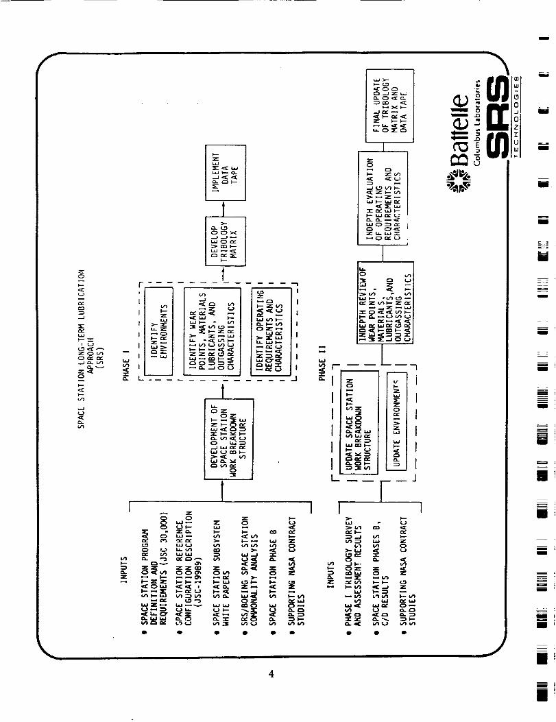
Phase II tasks for SRS were originally planned to accomplish an update of
these same tasks after the release of Space'Station Phase B SDR data packages and
again near the Phase C/D Space Station Preliminary Design Review. Figure 1
illustrates the logic flow of this appr0acft. SRS deliverables were to include a
comprehensive work breakdown structU_-:f0r the Space Station identifying major
moving mechanical assemblies (MMA), a complete list of operating characteristics,
materials, and environments for each:;_tified MMA used to support tribology
assessment, an identification of potential contamination sources on Space Station
(location and distribution of greases and lubricants), a data tape containing the
results of the tribology survey and assessment, and an identification of high priority
areas for further long-term lubrication study.
3
:- .=_=_
lit
i KLJ
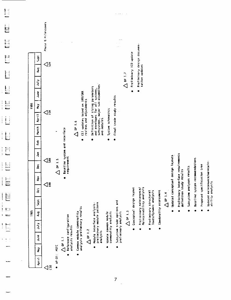
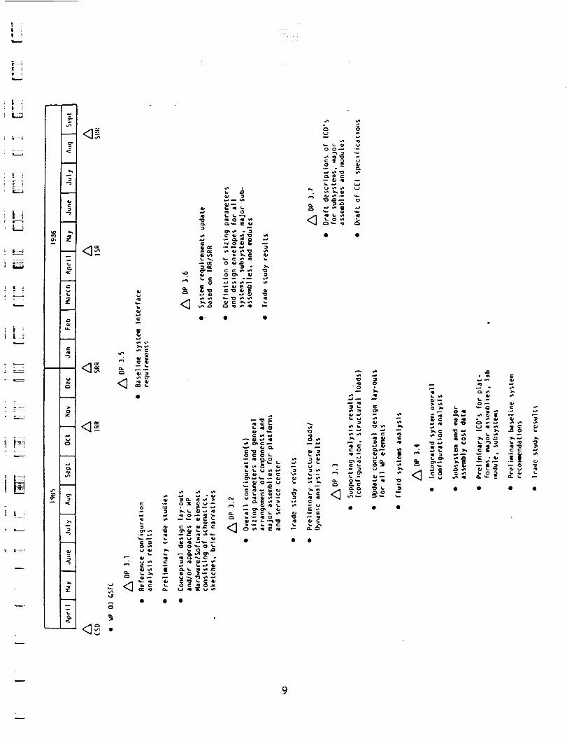
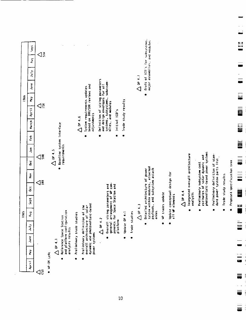
1.3 Project Schedule
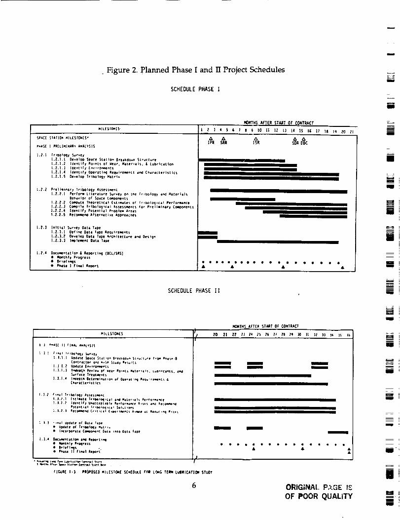
The original schedule for Phases I and II of the Space Station Long Term
Lubrication Study and major milestones are shown in Figure 2. Also shown on
the figure are the dates of major Space Stat-ion Program milestones as planned at the
start of the study. Close coordination was planned between the activities of this
study and the progress of design activities.Figures 3 through 6 show the expected
publication dates for major outputs of the four major space station work packages.
K_
L i
5
_ Figure 2. Planned Phase I and IT Project Schedules
SCHEDULE PHASE I
MONTHS AFTER STAAT OF CONTRACT
NIL[StOnES I Z ] 4 5 6 7 e 9 tO I| 12 D 14 15 13 IT 18 i9 20 _|
SPACE STATION NIL{STOkES"
P.a$[ [ PBELININAR_ aNALYSIS
l._.l Ir+OOlOqy Survey
).Z.I.I Develop Space SLation 8reakOo_n Structure
|._.|.2 l_enLify POinL$ of Wear, Materials. & LubricatiOn
1._.|.] |Oentif I [nvlrOnment$
i.Z.I.4 Ioentiry Operati_:J Requirements aeaJ C_aracterltt ic$
[.Z.I.5 Develop Trtbology Ma&rlz
|.Z.2 Preliminary lribotogy A$$etsment
[._.2.[ Perforl Literature Survey o_ tee trlbOIOqy and Nateria|_
Behavior of Space Component_
|._._._ Campsite Theoretical [$(imdtes of Ir_boloqtcal PerformanCe
|.Z.2.] Camp tie Triboloqical A$se$_nts for PreliminAty ComGonent$
1.2.2.4 [Oenctfy Potential ProDlem Areas
I.Z.Z.5 Rec_menO A|terhdtive ApprOdChe_
I.Z.] Initial Survey Data Tape
1.2.3+1 Oefie_e Data Tape Requtrement$
[.2.|.2 Develop DAta Tape Artht|etture and DesignL.Z.].| l_le_e| Data Tape
I.Z+a Oocuaentatloa & Repot|in 9 (BCL/$RS}
• _Onth|y ProgreSS
• 8rtefie_js
• Phase I FJm=l leporL
]PR SAP ISR SOP EOC
I
I
I
• & •
SCHEDULE PHASE II
i
i
I
iI
i
I
q
mmI
i
NIL[SIOt_[$
I ] P.t${ II +InAt anaLYSIS
] _ ['_41 l_lbOlO4_y Suevel
|. ].|.l UPdate SpaCl Silt 'O" SreatO0._ Structure ero_ _i_e.|
_Ont tic|or le_l k;$a Stu4_ |eSul_$
i, ],|rP U_late |m, erO+_N'+IS
I,].l. | I_lep_h levle, o+ veer Po_nts mate,,a_$. LuO+_¢a_tS, a_l
Surface TrOll.+hiS
I.J.I.4 I_ept_ Oetermt_tt +O_ of Ooe,at'_ri ee_u "rementS &C_aratterltt_¢t
|.l._ /" trill Trib¢loq)r AS_.eSSIIM'AI
I.]+_+1 |settee lrt_loqt¢=l i_ MILtr+#I_ Performae_:e
i.]+_+_ Identify Un4cceDl#Ole afrfo_t_ e a,_i_ 4_d le(Omm_ 4P_|enl_41 l_Oo;oq,c_l $olut,o_S
l.|._.] |fCOmIPev4 C¢_ticil (.petrifies &taueO _t ledu(,e_q li_i..
I ] | " ,_ll UOO+ItI Of 04el l_Ipe
• U_411e of tri_43tlt_l Natri=
• ie_cO¢_Oel|e C(l_oe_nl Ditl _Io Olt_l llpe
|,].a Oo(;_l'etltlOe IM leoorttml
air |el I_$P_l'.e l| fie,41 llpoel"
lllv_l q 11141 14me L_4eI(I|III _IIIeM4 111.1t qllllll flip ]fill _+11|II I (III.MI |11. I lilt*
rlr.ui[ 1.3 PIO_OS(D miLeStOnE SCx[OuL( _nR L_G T[Ikl LUIIICATIOn S_UOY
6
NONTX$ AFT(R ST_T OF CONTRACT
ZO 2| ZZ lJ Za _ II l_ l] 1_ _0 It )Z )) )a )_ I+
I I I
I I I
I
I I
I
• • • • • • • II • • e • • • • •
ORIGINAL P._.GE I-3
OF POOR QUALITY
m
M
i
i
m
m
m
I i
g +
L__U
i E
ER
w
r_
0.J
E E
7

• • • • •
I
m
mE
mE
i
u_
i
m
R
In
ImmmnU
mlira
i
m
um
m o
am
u
U _
f
=
J
O • •
i
m
i
10iNN
= =
| t
2.0 TECHNICAL ACCOMPLISHMENTS
During the Phase I efforts, a number of achievements occurred despite the
difficulties in obtaining solid detailed design information. Some of the results are
no longer applicable due to differences in the station configuration at the start of the
study and now, the "75 kW Space Station reference IOC" concept represented in Pre-
Phase B White Papers document and the current Space Station Freedom
Configuration. Also, atomic oxygen effects were just coming under close analysis
through data obtained from shuttle experiments. Since the time of these analyses,
the understanding of physical mechanisms and orbital environments has increased
significantly and may advance further in the near future as the results of the
recently recovered Long Duration Exposure Facility are analyzed and documented.
The results of the task activities are presented in greater detail in the following
sections of this report. Included are discussions of the development of a Space
Station Work Breakdown Structure, environment identification, wear points,
materials, lubricants, & outgassing, oper_ifirig-requirements and characteristics, and
the data tape.
=:= : .
J L=i
7 "_ 7 "¸
z_;̧ifi:=
|
11
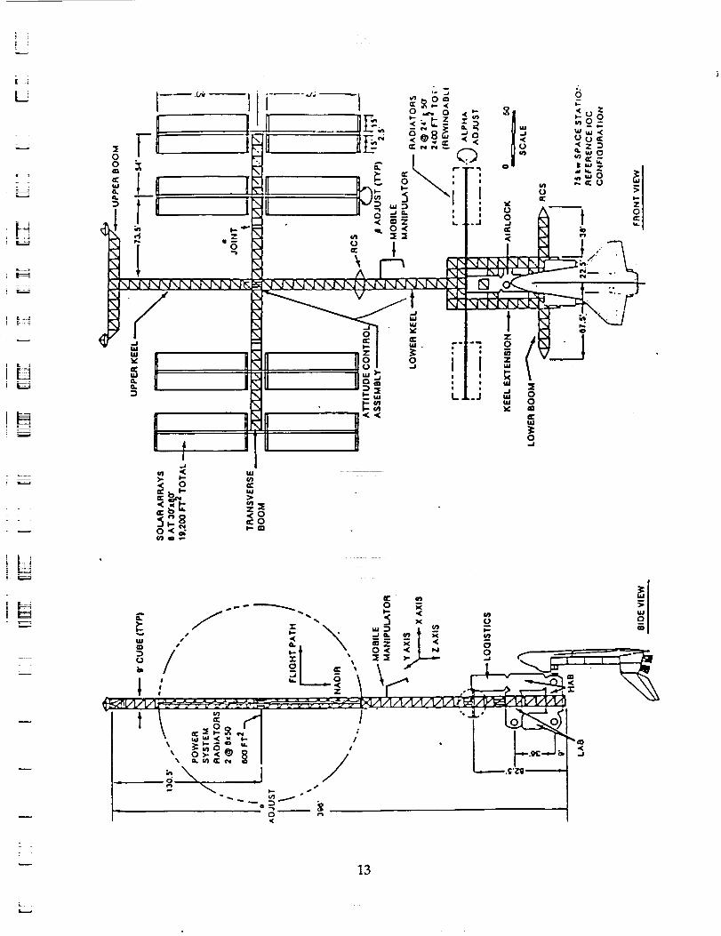
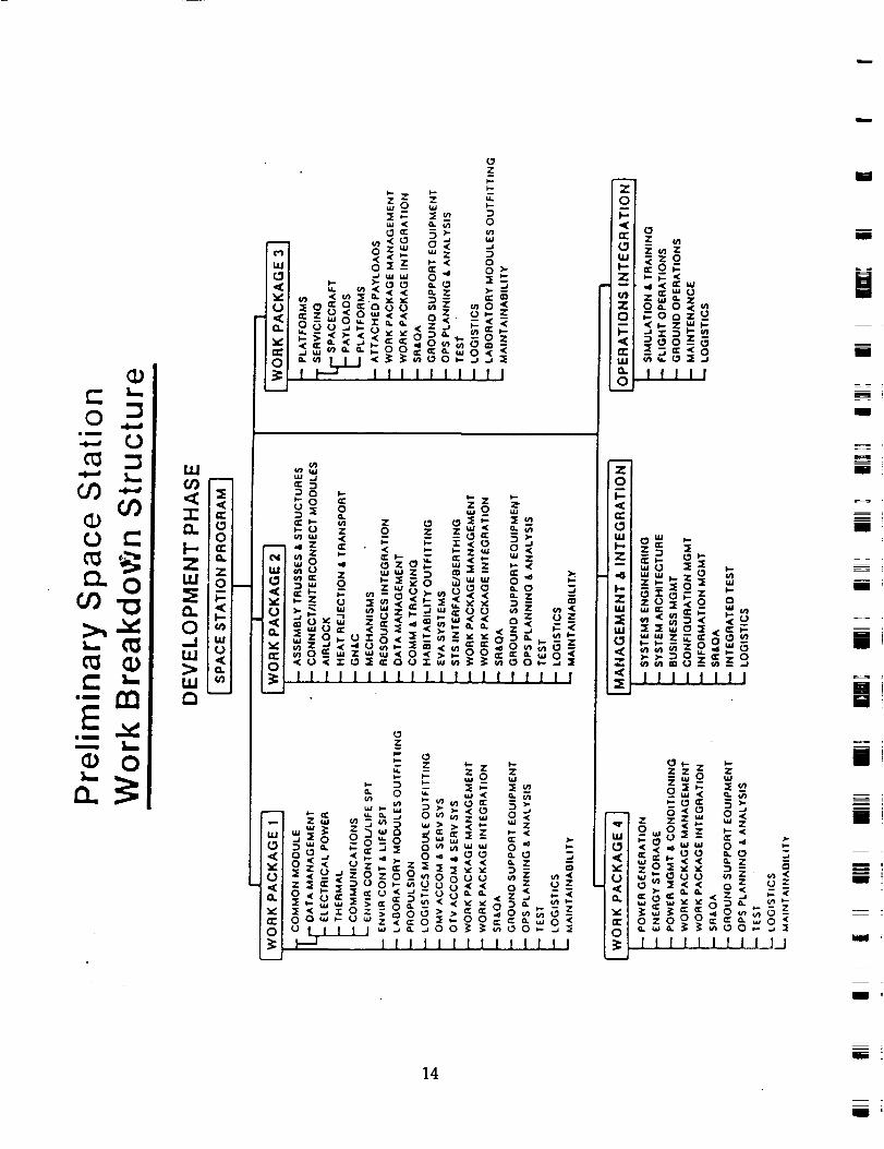
2.1 Development of Space Station Work Breakdown Structure
A comprehensive listing of the Work Breakdown including all major system,
subsystems, equipment, was developed and used as the basis for for identifying wear
points and critical lubrication concerns. The Space Station IOC reference
configuration shown in figure 7 served as the baseline configuration for this
analysis. This configuration is based on a set of deployed linear trusses constituting
the keel and booms to which the modules, subsystems, and equipment are
connected. It contains numerous mechanisms and joints that provide interfaces
with and support to external payloads and equipment for various experiments and
servicing functions (e.g., satellite, orbital/space transfer vehicle, and orbital
maneuvering vehicle servicing). Phase I of this program began about the time Phase
B of the Space Station program began in which there were still a number of parallel
contractors involved in each work package. SRS obtained design data products from
the Martin Marietta and Boeing Work Package efforts early in the study and
compared these with the reference configuration. Some variances occurred as can be
expected, especially at the lower levels. It should be noted that there existed an
official Space Station Work Breakdown Structure for the program, the top levels of
which are shown in figure 8. For the purposes of this study it was necessary to
modify the program WBS which includes functional elements (e.g., safety,
reliability, etc.). The WBS for this study was intended as a cataloging tool to promote
a complete identification of wear points in space hardware and therefore only
includes the breakdown of on-orbit hardware items. Much similarity exists in the
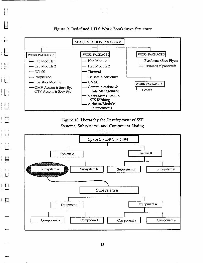
two items. Figure 9 depicts the difference in those structures at the top level. Both
agree at the program level and the project level definition was retained in
anticipation of continuing further with WP-1 than the others.
The basic concept of the hierarchical network as shown in figure 10 was used
to identify the Space Station breakdown structure levels and contents. The use of
this system to catalog and describe the large number of equipment hardware items
in the space station provided a systematic approach which was easily automated for
computer analyses of the interrelationships of all elements within a breakdown
structure level. Figure 11 illustrates the manner in which each level is subdivided to
provide a detailed listing of components and parts for identifying wear points. The
WBS structure levels were defined along the approach NASA uses.
i
I
m
im
m
I
= =
I
!
m
m ig
m
m
i
m
M
m
!
I
M
12i
U
L
!7!
! "_=_
iH
iN
m
t t
13
_ _ Zz_ Z
r_j _ Z _ _IZ_Z_l_zOlu, l _Z _< 0
--' u-- ¢_ 0 > _I ¢0_ __w 0 TM 2_ Zl_<
[]
_o_ -_ o_ Ol_Ooz_
_<<_ °__=°z _i_oo_P_ _
C _m L.L.J < _ _°_3 J2 _1 _ _
I _ IIIIIIIIII _llllll
09 _ z_
_0 Z 0 Z Z _ _m
=- - z=- ,,oo =o _/_:_;z _ i;
" " "" '"'""'"'" ii
- Z_ Z ZZ_
8<o
0 _ :_5_ o_ o _ _ _ <<_ . . _ _
3 _:ouo _z _< _ i
__ >_ <_ _ _- Z
= oo--U_z<=o_-99====o_ : ozone= ==0_<
H lllllllllJllll },lllllllllJJ i_
14
=Bi
i ;
k._
b
L
L
iLi
'LIi :i
Figure 9. Redefined LTLS Work Breakdown Structure
1I I
m Lab Module 1
m Lab Module 2
m EC LSS
Propulsion
Logistics Module
OMV Accom & Serv SysOTV Accom & Serv Sys
I SPACE STATION PROGRAM I
WORK PACKAGE
Hab Module 1
Hab Module 2
Thermal
Trusses & Structure
GN&C
Communications &
Data Management
Mechanisms, EVA, &
STS Berthing
I[ WORK PACKAGE 3 I
L Platforms/Free FlyersPayloads/Spacecraft
II_°_C_ I
L Power
Interconnects
- -_±
Figure 10. Hierarchy for Development of SSF
Systems, Subsystems, and Component Listing
| _
II
I
Space Station Structure I!
II
I I
I
ISystem X I
ISubsystem y
!Equipment 1 [
tComponent a [ Component b ] ] Component x
IEquipment n ]
1I
15
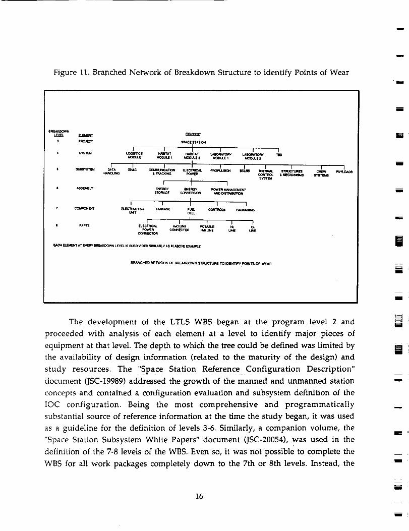
Figure 11. Bra_nched Network of Breakdown Structure to identify Points of Weari
$ SUESYSTI_
11 ASSEMgLY
7 COMPONENT
I PART8
e RF._KIX:X_m
,1 PROJECT SPACE STATII_Ii
I I J I I 1
4 5YSTIEkl LOGISTICS HABITAT 14AB/TAT LA_TORY LAIIOPATORY TOO
MODULE MOOULE 1 MOOULE 2 MOOULE _ MOOULE 2i
I I I J I I I I I I
DATA GNAC COI_MUNk_.A TION ELECTRICAL PR(_IIU._K_I EcL.q8 THERMAL STRIJC TLIRI_ CREW PAYt_
HANO(.INO & TRACKING POW_ _ & _S SY_'Ekil6$YSTIgd
f J I
I I J I I
E].EC'rlqOLY$1S TANKAGE _ CONTROI_ PACKAGINGUNIT CELL
I I I I I I
ELECTR_AL I-bO LINE POTABLE I_ OePOIA_ Pl CONNECT_ HIO LINE Lk_'4E LINE
CONNECTOR
EACH ELEMENT AT EVERY BREAKDOWN LEVEL IS SUBOMDED SIMILARLY AS IN ABOVE EXAMPLE
BRANCHED NETWORK OF BREAKDOWN 5TRUC'rURE TO IOENTIFY POINTS; OF WEAR
The development of the LTLS WBS began at the program level 2 and
proceeded with analysis of each element at a level to identify major pieces of
equipment at that level. The depth to whicl_ the tree could be defined was limited by
the availability of design information (related to the maturity of the design) and
study resources. The ',Space Station Reference Configuration Description"
document (JSC-19989) addressed the growth of the manned and unmanned station
concepts and contained a configuration evaluation and subsystem definition of the
IOC configuration. Being the most comprehensive and programmatically
substantial source of reference information at the time the study began, it was used
as a guideline for the definition of levels 3-6. Similarly, a companion volume, the
"Space Station Subsystem White Papers" document (JSC-20054), was used in the
definition of the 7-8 levels of the WBS. Even so, it was not possible to complete the
WBS for all work packages completely down to the 7th or 8th levels. Instead, the
J
N
zJ
m
i
M
i
M
m
J
mWi !
m
i
16
m
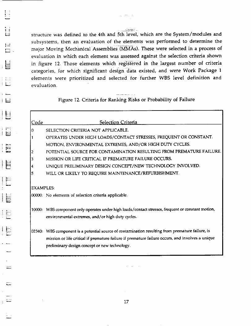
|
i J
_z_
m_t! !_,
_L z
J _ "_
structure was defined to the 4th and 5th level, which are the System/modules and
subsystems, then an evaluation of the elements was performed to determine the
major Moving Mechanical Assemblies (MMAs). These were selected in a process of
evaluation in which each element was assessed against the selection criteria shown
in figure 12. Those elements which regi_s_ered in the largest number of criteria
categories, for which significant design data existed, and were Work Package 1
elements were prioritized and selected for further WBS level definition and
evaluation.
Figure 12. Criteria for Ranking Risks or Probability of Failure
Code
0
1
Selection Criteria
SELECTION CRITERIA NOT APPLICABLE.
OPERATES UNDER HIGH LOADS/CONTACT STRESSES, FREQUENT OR CONSTANT.
MOTION, ENVIRONMENTAL EXTREMES, AND/OR HIGH DUTY CYCLES.
POTENTIAL SOURCE FOR CONTAMINATION RESULTING FROM PREMATURE FAILURE.
MISSION OR LIFE CRITICAL IF PREMATURE FAILURE OCCURS.
UNIQUE PRELIMINARY DESIGN CONCEPT/NEW TECHNOLOGY INVOLVED.
WILL OR LIKELY TO REQUIRE MAINTENANCE/REFURBISHMENT.
EXAMPLES:
00000: No elements of selection criteria applicable,
10000: WBS component only operates under high loads/contact stresses, frequent or constant motion,
environmental extremes, and/or high duty cycles.
02340: WBS component is a potential source of contamination resulting from premature failure, is
mission or life critical if premature failure if premature failure occurs, and involves a unique
preliminary design concept or new technology.
17
= .
2.2 Environment Identification
Establishment of the environments for each wear point was required for the
assessment of performance and life characteristics of the particular surfaces of
interest in the identified wear points. In general, environments enclosing surfaces
in relative motion can be different depending on the duty cycle of the mechanism.
For example, when the mechanism is not operating, the environment may be at a
different temperature and pressure than when the mechanism is operating.
Mechanisms at rest may, however, be under static load and, depending on materials
and environments, failures such as long term stress corrosion may occur. If high
loads and;or high relative speeds are present such as in the contacts of high speed
rolling bearings, temperature in the contacts will be vastly different from those for
static conditions. These thermal environments and temperature cycling set
stringent requirements on long term lubricants and the ability of the lubricants to
provide the necessary elastohydrodynamic for proper lubrication at operation
temperature. In general, the life of these contact surfaces is dependent on the
elastohydrodynamic conditions in the contacts which is a complex function of load
levels, speeds, and operating environment.
In some specific applications, such as the Space Station refrigeration systems,
the lubrication system for refrigerant compressors may require isolation to prevent
lubricant contamination of evaporator and condenser surfaces. In some designs this
may involve dynamic seals in a refrigerant and high temperature lubricant
environment. These environments must be identified and characterized to support
wear and life assessments of these components. Other mechanisms, such as
external fluid rotary joints and docking mechanisms, will have external surfaces
exposed to the space environment for long periods of time. Lubricants used for these
applications must therefore be compatible with these environments. The
assessment of environmental effects on contacts and/or wear point performance,
durability, and life requires a definition of these environments over the entire duty
cycle of the mechanism and/or component.
The objectives of this effort were to identify the environment for each wear
point over the duty cycle of the mechanism, characterize the environment for
assessment of wear point durability and life, provide comprehensive rationale to
support findings, data base, and documentation requirements. Environments over
the complete duty cycle were determined for each Space Station MMA component.
18
mu
m
I
[]
I
m
mm
I
m
mI
m
mi
m
m
i
lI
t_I
u
k_
L
=
These environments were then characterized to determine the specific
environmental component s that affected wear point performance and durability.
Many components, such as thermal control coolant pumps, essentially
operate continuously at relatively steady loads. Other components, such as docking
mechanisms and latches, may not operate over several times per year. Mechanisms
such as Space Station Solar Array actuators and drive mechanisms will operate
several times per orbital period. These++are examples of mechanisms that have
relatively steady environments and large fluctuations in environments depending
on duty cycles. Surfaces exposed to the orbital environment (latches, docking
probes, etc.) will be exposed to many elements that could cause surface degradation
leading to loss of performance and decreased durability. The space environmental
effects most likely to affect materials and lubricants in Low Earth Orbit are:
• Vacuum Outgassing (1 X 10 -6 to1 X 1:0-7 Torr (per specification SP-R-0022A)
• Solar Radiation
- Proton - 2.9 X 10³ rad (c), Energy >100 keV to 2.2 X 10³ rad (Si)
- Electron - 7.5 X 10⁵ rad (C), Energy >40 keV to 6.8 X 10⁵ rad (Si)
- Ultraviolet - 55,000 Sun Hours
• Atomic Oxygen
- Concentration - Approximately 1 X 10⁹ atoms/cm3 @ 290 nmi. altitude
- Exposure - perpendicular to Flight Path
- 2.36 X 10¹⁵ atoms/cm2/sec
- 3.5 X 10²⁰ atoms/era2 in 41.0 hours
• Micrometeoroids - 8200 impacts/m 2 (mass < 10-12 gin)
+ Meteoroids & Debris - 4 impacts/m 2 (diameter > 0.01 an)
• Thermal Cycles - 58,500 over 10 years
The space vacuum has varied effects on materials depending on the material
characteristics. For example, it has a beneficial effect on the fatigue life of alloys
susceptible to stress corrosion (removed or absorbed molecules eliminating the
electrolyte).+ Vacuum and thermal effects can cause removal of surface gases from
materials with detrimental effects. Losses of absorbed gases for materials in sliding
surfaces can cause appreciable changes in friction coefficients. Lubrication
characteristics may also change significantly when exposed to space vacuum over
long periods of time. A lubricant's volatility is a function of its vapor pressure, and
vapor pressure is related inversely to molecular weight. In general, lower weight
19
fractions of a lubricant will be lost through vaporization before the heavier
constituents. This does not necessarily mean that those with very low vaporpressure and evaporation rates will give the longest life in vacuum service. The
only conclusive means in determining lubricant service life in vacuum is by
experimentation. Long term tests of grease type lubricants are underway at MSFCand will provide valuable information for the assessment of long term vacuumeffect on these lubricants.
In low earth orbit the principal source of electromagnetic radiation is the sun.
Solar radiation covers the wave length region from around 0.01 _m to greater than104 _tm. This region includes low energy gamma ray, x-ray, UV, visible, infrared,
and microwave photons with an energy density of 1353 W/m 2. In developing thesolar environments for specific components the lOcation of the component relative
to the sun and earth is important as well as shading and/or blockage from adjacentstructures. For estimates of material degradation due to sun exposure, total exposuretimes will be estimated based on orbital time averages of solar exposure for each
mechanism. Solar flux distributions for outer surfaces of the Space Station will bedeveloped by Phase B contractors for thermal design of SSF. This will be the
principal source of data for this environmental information. In specific caseswheredata may not be available, SRShas the capability to develop this information.
The trapped particles of the South Atlantic Anomaly are essentially electronsand protons trapped in magnetic flux lines an reach a low point at about 30 degrees
inclination or greater, there will be approximately five passes through thisanomalous area each 24 hours. Material degradation occurs through ionization of
the atoms or molecules by the electrons and energy deposition in the materials by
protons.Atomic oxygen effects on materials and surface degradation is a strong
function of the direction of the surface with respect to the velocity vector. Thegreatest amount of degradation occurs on the forward surface of the STSOrbiter
perpendicular to the velocity vector. Therefore, atomic oxygen fluxes must beestimated based on the relative location of the surface of interest. Materials
experiments have been flown on many STS flights and data reported in the
literature. The recently retrieved Long Duration Exposure Facility should providesome very relevant information from AO experiment results.
During the LTLS study, the responsibility for leading space station propulsionsystem design was being transferred to JSC.Mr. Walt Karakulko at NASA/JSC was
m
i
I
r_
m
I
I
ml
I
I
m i
u
i !
U
20m
l
2 i
contacted and provided these guidelines on operating characteristics of the space
station thruster/storage tank assembly.
gaseous fuel: <3000 psi; (20 deg. F.)<T<(150 deg. F)
liquid fuel: 400-500 psi; (20 deg. F.)<T<(150 deg. F)
i o
[,....a
=
21
2.3 Identification of Wear Points i
In this section, the activities performed in pursuit of the tribology survey data
and the MMA's identified in this process are discussed. This first subsection
summarizes these activities and includes a list of the MMA's selected. Succeeding
subsections discuss each MMA separately.
2.3.1 Summary
From a relatively broad range of assemblies, components, and mechanisms, a
group of items were selected for focus in the evaluation and assessment activities.
For these items, a contacts were established, usually with the NASA technical
monitor and the contractor (or subcontractor) performing technology studies or
advanced developments for the items. In many cases SRS met with project leaders
and discussed lubrication concerns directly with the individuals involved in the
studies. This was made possible in most cases by scheduling splinter sessions in
conjunction with SS Phase B Work Package Reviews and SS Advanced
Development Program Reviews held at MSFC. The list of areas below comprise this
set of target projects.
m
m
m
mmm
g
i
J
Collection of data and survey of lubrication aspects of:
o OMV Mechanisms,
o Mobile Servicing Center,
o SS Control Moment Gyro,
o MDAC Berthing Mechanism,
o GE Compressor,
o Rockwell Rotary Joint Mechanism,
o MDAC Rotary Joint Mechanism,
o Sperry Rotary Joint Mechanism,
o Space Station Alpha Rotary Joint Mechanism,
o Space Station Propulsion Thruster/Storage Tank Assembly,
o Space Station Solar Array and Solar Dynamic Concentrator,
o OMV and Payload Mechanisms,
o Antenna System Rotary Joints, and
o Health Maintenance Facility.
22
i
m
m_
m
m
m
m
mm

L
z
i Liz_
ILii L i,
Lubrication issues, although of concern to all such projects, were not the
main goal of most of these projects. Typically, the objectives were to assess relevant
technologies in areas like mechanisms, power generation, or LOX/LH2 propulsion
concepts and produce proof-of-concept prototypes. Therefore, the effort which these
projects could put forth in coordinating _th the LTLS was limited. In all cases, SRS,
in conjunction with the COTR for this study, Mr. Fred Dolan, sent written requests
for pertinent information and provided lubrication survey forms. In several
instances, the projects were able to make an assessment and provide very useful
feedback. In other cases, the projects provided data products (technical reports,
concept descriptions, design drawings, etc.) which allowed SRS to perform
assessments for lubrication concerns connected with the item. Also, through
alternate sources and basic research, enough information was obtained to make
some evaluation. Some projects never reached a level of maturity to support
definition of all the the structural, mechanical, lubricant selection, outgassing
information necessary for a complete survey of the concern. Looking forward to
updates planned for later in the LTLS project, SRS retained these items in the
tribology data base with as much informati0n as was available.
In addition, SRS continued to track the the global program to monitor for the
identification of additional lubrication concerns/items as they became apparent.
Those activities included acquisition and assessment for wear points in Boeing WP-
1 and SS ADP Review Data, participation in Space Station Materials Sub-Panel
Meeting at NASA/Langley Research Center, communications with MSFC, Phase B
contractors, and ADP's to obtain environment and operating characteristics of
MMA's, and coordination with ADP centers to request inclusion of the completed
Survey Forms as part of Phase C/D PDR data requirements.
At the Langley Materials Sub-Panel Meeting, the issue of design maturity and
the timeliness of LTLS study products was addressed. In response to the need for a
tribology assessment for the Major Moving Mechanical Assemblies (MMA's) prior
to their respective Critical Design Reviews (CDRs), the LTLS study aproach was
revised. The initial approach was based on making use of Design data published in
Preliminary Design Review (PDR) data packages. However, this data has been
neither complete nor mature enough to support a tribology assessment. It has been
determined a more direct method of obtaining environmental and operating
characteristics of the MMAs is needed if the tribology assessments are to be made
before CDR.
23
m
To resolve this problem, the tribology survey forms previously developed in
this study for in-house use, were sent to the responsible COTR's and contractors
prior to design reviews. Letters .of explanation and Survey Forms were sent to:
m
i
o Sperry -Alpha and Beta Rotary Joints
o Boeing -Gimballed Radiator and Two Phase Thermal Bus
o Grumman -Space Erectable Radiator and Two Phase Thermal Bus
o General Electric -Compressor for SS Refrigeration system
o MacDonnell Douglas -Berthing Mechanism
In addition, a letter and survey form encouraging their inputs to this study
were sent to David Thomasson of the Huntsville Boeing office. Boeing Aerospace
Company is an MSFC WP-1 Prime Contractor. Also, a complete set of the red-books
containing the presentation materials from the Space Station Advanced
Development Program Review were obtained and reviewed for information
indicating possible Major Moving Mechanical Assembly candidates for further
lubrication study in this program.
2.3.2 Orbital Maneuvering Vehicle & Mobile Servicing Center
i
m
m
m
im
I
I
John Forbes/MSFC, the manager for Orbital Maneuvering Vehicle (OMV)
Mechanisms was contacted and agreed to follow through in providing wear point
information towards the objective of developing a survey response. The OMV
became an LTLS topic of focus when SRS attended the annual review of the
Grumman Aerospace "Advanced Orbital Servicing Technology" effort at MSFC on
June 24. No hardware design activities pertinent to this study were identified as part
of that AOST study, but during the review suggestions were made to research the
mechanisms on the Mobile Remote Manipulator System (MRMS) and the Orbital
Maneuvering Vehicle (OMV). SRS followed up in the pursuit of lubrication aspects
of the mechanisms on the Mobile Remote Manipulator System (MRMS) and the
Orbital Maneuvering Vehicle (OMV) by contacting Luther Powell, then director of
the MSFC Space Station Program Office. He provided SRS with a contact in the
MRMS program-Brian Erb of the NASA Johnson Space Center. JSC was to develop
the base with SPAR of Canada providing the manipulator arm. In initial discussions
with Mr. Erb, he indicated project was still very much in the conceptual phase, but
he would do some checking and call back on the availability of data. Later, Brian Erb
24
=I
U
m
ml
LI
m
I '
m .
Z_
I
L i
L
i
_L
(also of the Canadian Research Council) was sent LTLS survey forms and forwarded
them to appropriate technologists. There was no further response from that source.
Additional discussions with Zack Th0m_n, Stan MacIntyre, and Tom Byrd of
MSFC indicated there was some potential for lubrication issues associated with
fluid, electrical, and payload quick disc_on_cts. In a follow-up to that meeting, Tom
Byrd of NASA/MSFC indicated three design areas with possible lubrication
concerns and agreed to supply pertinent data on:
(1) 3-point latch mechanism for Space Telescope,
(2) Fluid coupling for propulsion system, and
(3) Payload gimbaling.
Also, on July 16, 1986, SRS sent a letter to Mr. Jeffrey Corbin of Martin
Marietta requesting contacts to provide data on OMV/OTV Accommodations items
relating to docking mechanisms and pumps from their Phase B work:
2.3.3 Space Station Control Moment Gyro ....
_L
!L
w
T ,
L
z
z
Early conversations with Lewis Cook, COTR for this Bendix project indicated
that a survey was underway for supporting mechanisms with an expected time of
completion is two weeks. In the Attitude Control and Stabilization session of an
ADP program review held later, Mr. Cook of MSFC presented the status of a Control
Moment Gyro design activity. Parts 0f this system were currently on order for a
CMG prototype. However, only limited design data pertinent to lubrication was
available.
2.3.4 GE Compressor
Lockheed Missiles and Space Company studies of mechanical assemblies in
the Thermal Storage Unit and Refrigerator System focused on the GE compressor.
Mr. Rudy Trabanino of NASA/JSC agreed to forward a survey data form to the
appropriate individuals at the General Electric operations in Houston. A survey was
sent for the advanced development program they were pursuing on a Compressor
for the Space Station Refrigeration system. Later, Mr. Trabinino requested additional
survey forms to send to General Electric. During the project, GE Houston operations
underwent a cut in workforce. The original request and form may have been lost.

2.3.5 Truss & Rotary Joint Mechanism
Discussions with Leon Smith of the McDonnell Douglas Astronautics
Company identified Lockheed Missiles and Space Company as the provider of a
rotary joint design as part of the Work Package 2 Phase B activity. However, not
enough detail was then available to justify a survey. The competition sensitive
nature of the design/configuration was expected to limit the availability of
significant design information until mid to late 1987.
Lubrication survey data forms were provided to Mr. Harley Rockoff of
Rockwell for their Rotary Joint Mechanism work. A second request was made as a
result of an Space Station Advanced Development Program Review meeting held at
LaRC.
Conversation with Fred Jankowski of NASA/MSFC indicated that little
pertinent information to support a tribological analysis of the McDonnell Douglas
Rotary Joint Mechanism was available at the ADP review. Detail drawings were
only beginning to be prepared at the time.
John Gustasson of NASA/LaRC was contacted and agreed to send a package of
documentation containing all available design information on the Space Station
Truss and Joint Designs being sponsored by LaRC.
Mr. Obie Bradley of the NASA Langley Research Center provided SRS with a
report on testing and design drawings of three Rotary Joint Mechanism concepts.
Upon Evaluation of the Sperry Alpha Rotary Joint Design Drawings, seven areas of
potential wear problems were identified:
m
I
m
[]
mm
I '
m
m
m
I
(1) Power/Signal Transfer Bearing
(2) Pinion Gear/Bearing Housing Gear Interface
(3) Shaft Bearing (P/N 3HKR102 P7)
(4) Pinion Bearing (P/N KAA10 AG)
(5) Follower Bearing (P/N KB020 CPO)
(6) t_ Solar Array Joint 36 inch Bearing Assembly
(Alternate Construction)
(7) Alpha Solar Array Joint 108 inch Bearing Assembly
(Alternate Construction)
mI
!
26
I

E •
L
Along with the preliminary survey data forms, other pertinent drawings and
specifications were sent to Battelle Columbus Laboratories for further tribology
assessment.
Harold Bush of NASA/LaRC) was contacted and agreed to send a package of
documentation containing all available design information. SRS received a data
package on a preferred truss concept (several were still being considered). After
review of this package, additional information on a few specifics was requested.
The rotary joints in the antenna system had similarities to the Ball Aerospace
and Sperry designs in the solar array application. Jim Kelly of NASA/JSC, agreed to
send lubrication reports and drawings on the shuttle KU band antenna gimbal
system. That system was produced by Hughes Aircraft in E1 Segundo, California.
z,=
2.3.6 Berthing Mechanism
The McDonnell Douglas Astronautics Company began Berthing Mechanism
design activities in mid 1986. In July, at the request of SRS, Mr. Fred Jankowski
MSFC/EP33 forwarded a survey data form to MDAC for completion. Results were
expected on or about August 1986.
2.3.7 Radiator
Parish of NASA/JSC, LTLS survey forms wereThrough Mr. Richard
distributed to appropriate individuals at the Boeing Aerospace Company for the
Two Phase TCS and Gimbal Radiator and Grumman for the Two Phase TCS and
Space Erectable Radiator. In follow-up discussions it was reported that they were
being prepared and might be available within a month.
t-...,
2.3.8 Coarse Pointing Mechanism
In telephone contacts with Kevin Grady of the NASA Goddard Space Flight
Center, the Coarse Pointing Mechanism project was still in a very conceptual stage.
He suggested contacting the work package 2 contractors General Electric and Ball
Brothers again around the first of September when more mature data may be
available.
2.3.9 Propulsion System Thrusters
27
i
Mr. Ralph Burns MSFC/EP33 provided SRS with a data package containing a
schematic and drawing of portions of the space station thruster/storage tank
assembly. SRS reviewed this information to identify possible wear point candidates.
Initially, potential areas of concern included O-rings, V-seals, K-seals, screw threads,
fuel/oxidizer quick disconnects, and solenoid and latching valves. In the end, the
SRS evaluations resulted in the identification of 36 wear points with possible long-
term lubrication concerns. The points identified were associated with the fuel and
oxygen solenoid valves, the oxygen and nitrogen latching valves, and the thruster
assembly.
During this time, the responsibility for leading space station propulsion
system design was being transferred to JSC. Walt Karakulko at NASA/JSC was
contacted and provided these guidelines on operating characteristics.
gaseous fuel: <3000 psi; (20 deg. F.)<T<(150 deg. F)
liquid fuel: 400-500 psi; (20 deg. F.)<T<(150 deg. bO
On July 16,1986 SRS sent a letter to Mr. Jeffrey Corbin of Martin Marietta
requesting contacts to provide data on items from their Phase B work on the Space
Station Propulsion System including an electromechanical solenoid quick
disconnect fitting, thruster valves, isolation valves, and propellant/pressurant quick
disconnects.
2.3.10 Solar Array
Mr. Wayne Bartlett of the NASA Lewis Research Center provided SRS with
three sets of detailed notes on lubrication aspects of the LMSC Space Station Solar
Array. His notes included a drawing and addressed mechanical assemblies at the
base of the array connecting to the Beta joint. Another set of notes prepared by Mr.
Rick Elms of LMSC identified a large number of wear points and proposed
lubricants for locations on the array, base, ancl deployment mechanism. Also
included was a copy of a memo from Mr. Fred Dolan MSFC/EH14 to Ann Whitaker
MSFC/EH12 on the lubrication recommendations for the Solar Electric Propulsion /
Solar Array Flight Experiment dated February 15, 1979. Although the depth of
information was limited in these notes, they were sufficient to identify the location
of potential lubrication concerns and some candidate lubricants for evaluation.
From this information, SRS identified a number of wear points and collected
28
i
I
m
i
I
m
i
ii
D
r_
g
i '
u
[]
miI
g
i
i
i
iii
|
i|
Mii
m
ii

2
: = :
tribology data associated with the items. SRS concentrated mainly on the
component description and materials summary. Mr. Bartlett later met with SRS
contract representatives, providing survey forms completed by Rocketdyne also on
components of the Solar array structure. The information was complementary since
Rocketdyne concentrated on operating characteristics and also served to verify the
points identified. Mr. Bartlett anticipated sending more detailed drawings/pictures
of the individual components as they became available. A total of eight wear points
were identified and surveyed in connection with the solar array and solar dynamic
generator components.
2.3.11 Health Maintenance Facility
The in-flight clinical medical care facility onboard the Space Station was still
in the definition process, according to Mr. James Logan, Medical Operations Branch
Chief, at NASA's Johnson Space Center when he was contacted by SRS. Some small
pumps were potential sources of lubricati6ffconcerns, but design candidates had not
yet been defined.
-_ a! i i
|:!
i !:!
] L_ :J : :z
29

2.4 Operating Requirements and Characteristics
Lubrication schemes may be classified according to the general type of
lubricants, whether dry film or fluids. Typical dry film lubricants include MoS2,
Teflon, and graphite. Typical fluid lubricants include oil and greases. Determining
the type of lubrication scheme for a specific element and the performance
characteristics of the lubricant to reduce surface wear is an important factor in
support of tribology assessments. However, the type of lubrication scheme depends
on the operating characteristics of the component such as loads, rotational speeds,
relative velocities and environment. Consequently, a characterization of lubricants
and operating characteristics was necessary.
Lubricants operating near optical or thermal control surfaces were assessed
against the outgassing requirements defined in SP-R-0022A, "General Specification
Vacuum Stability Requirements of Polymeric Material for Spacecraft Application".
This outgassing requirement restricts the use of polymeric materials near critical
optical and thermal control surfaces to those materials having a maximum volatile
condensed material (VCM) content of 0.1 percent and a total mass loss (TML) of 1.0
percent or less when tested under the following controlled test conditions:
0
0
0
0
Pressure: 10-6 torr or less
Temperature of Specimen: 125 deg. C - 1 deg. C
Temperature of Condensable Plates: 25 deg. C - 1 deg. C
Vacuum Exposure Time: 24 hours
Representative outgassing data for typical greases and lubricants are listed in
Table 1. SP-R-0022A defines specific procedures for NASA approval of polymeric
material selected for application near optical and thermal control surfaces. These
procedures served as a baseline guide to evaluate the performance characteristics of
lubricants identified during the survey. The pertinent survey data base data
consisted of listing:
0
0
0
0
Manufacturer's trade name
Manufacturer of the material
Thermal vacuum stability (VCM and TML) data
Rationale for use of material which failed outgassing requirement.
30
mg
I
m
L _
mm
l
i
i
z
m
i
u
g
I
j
R
I
ml
!l
m
W
U
= =

L :
w
! J
w
i.+
1 [
; i +
f
i|vli
-!_.jlI
e
II
;i
i
• .._ ........... , _ ........... _._. •
• ''_ ............. o_ "___'_"
=., , .., ! !tt_ . f -- d_itl
___.. _.+o.... _ !---!1 .l _-o o-ili_l
...................+,_,!• -,.,_ooo....._.....!_!_ _ _i_....i....i_.mmmmm
.o_lliitt oooooooo + I +----i m ulllllllllil :+l1t ltlil
lllttt+ttlllllllli_ _..............--.:_ltltttill'--''--
J
31
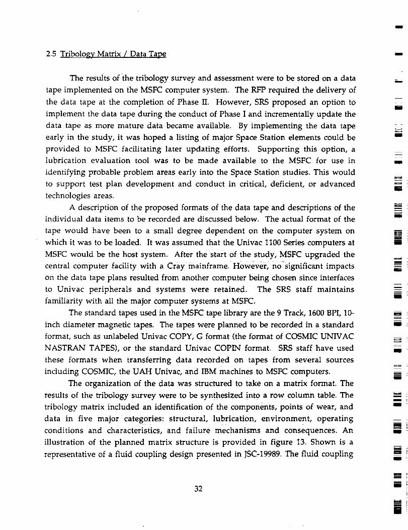
M
2.5 Tribology Matrix / Data Tape
The results of the tribology survey and assessment were to be stored on a data
tape implemented on the MSFC computer system. The RFP required the delivery of
the data tape at the completion of Phase II. However, SRS proposed an option to
implement the data tape during the conduct of Phase I and incrementally update the
data tape as more mature data became available. By implementing the data tape
early in the study, it was hoped a listing of major Space Station elements could be
provided to MSFC facilitating later updating efforts. Supporting this option, a
lubrication evaluation tool was to be made available to the MSFC for use in
identifying probable problem areas early into the Space Station studies. This would
to support test plan development and conduct in critical, deficient, or advanced
technologies areas.
A description of the proposed formats of the data tape and descriptions of the
individual data items to be recorded are discussed below. The actual format of the
tape would have been to a small degree dependent on the computer system on
which it was to be loaded. It was assumed that the Univac 1100 Series computers at
MSFC would be the host system. After the start of the study, MSFC upgraded the
central computer facility with a Cray mainframe. However, no significant impacts
on the data tape plans resulted from another computer being chosen since interfaces
to Univac peripherals and systems were retained. The SRS staff maintains
familiarity with all the major computer systems at MSFC.
The standard tapes used in the MSFC tape library are the 9 Track, 1600 BPI, 10-
inch diameter magnetic tapes. The tapes were planned to be recorded in a standard
format, such as unlabeled Univac COPY, G format (the format of COSMIC UNIVAC
NASTRAN TAPES), or the standard Univac COPIN format. SRS staff have used
these formats when transferring data recorded on tapes from several sources
including COSMIC, the UAH Univac, and IBM machines to MSFC computers.
The organization of the data was structured to take on a matrix format. The
results of the tribology survey were to be synthesized into a row column table. The
tribology matrix included an identification of the components, points of wear, and
data in five major categories: structural, lubrication, environment, operating
conditions and characteristics, and failure mechanisms and consequences. An
illustration of the planned matrix structure is provided in figure 13. Shown is a
representative of a fluid coupling design presented in JSC-19989. The fluid coupling
32
I
m
i
m
I
!
m
m
U
m
R
El
g
m
U
!g
m
m
m
m
m
U
g
m
n
m

L
L]L
= ,
has been broken down to the structured element level, and materials, surface
finishes, environments, and oeprating characteistics have been identified.
,_:_ F_///////////_ ' .......' .. \_- '-"""- 1IF- ,.,,,.--,
l ! ,1¢9,. Tr( i l-I. I,,_h / I o,'1 I _l._r_t.d I OI m, -Cot
I I_..... ,,, I ,, , , ..,..,..,,,
, _.:_
$otin
16e
,SlyIA'tJl
, tl,Sie_re
J_,r_
Fillvrlr _C _a_ _(onSeqvence_
iUT_
33

3.0 CONCLUSIONS
Upon completion of the Phase I activities, the information was organized
into the tribology matrix format and compiled into a preliminary tribology matrix as
depicted as table 2 in the following pages. The information necessary to provide
meaningful indications of failure mechanisms and consequences was not available
and was deleted from the format. Originally, there were planned to be two updates
to the matrix. Those updates were eliminated in the renegotiations of the contracted
effort. Since the LTLS program was brought to focus on a few items early in the
program, there no longer existed a need for a computer system to host and
manipulate vast amounts of data. Early data base programming efforts using the
RIM 5 relational data base software were discontinued when it became apparent that
a different scope was prudent in the data requirements of the project. Appendix A
contains the individual data sheets prepared from the survey results for each of the
line items summarized below.
Most of the wear points identified were in conjunction with the RCS thruster
assemblies and the solar array. A few wear points were identified for the Beta Joint,
the Solar Dynamic Concentrator, and pumps in the fluid control system.
M
I
m
u
U
m
I "
m
i
U_
g z
g
34
m
mz
!
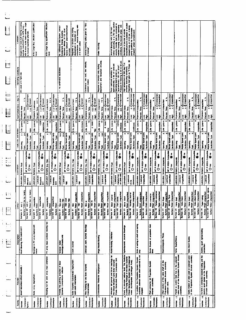
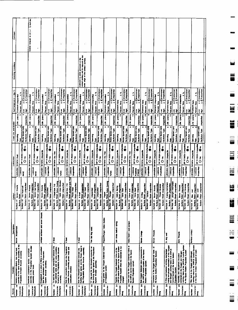
l
i
m
mm
g_
II
[]m
ml
Im
mid
Ill
___E4.uim
M
mDi
um
mB
mm
I
m
U _
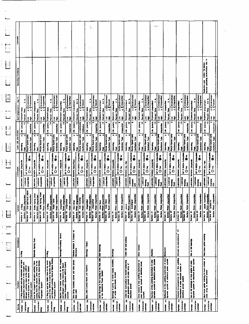
,k....
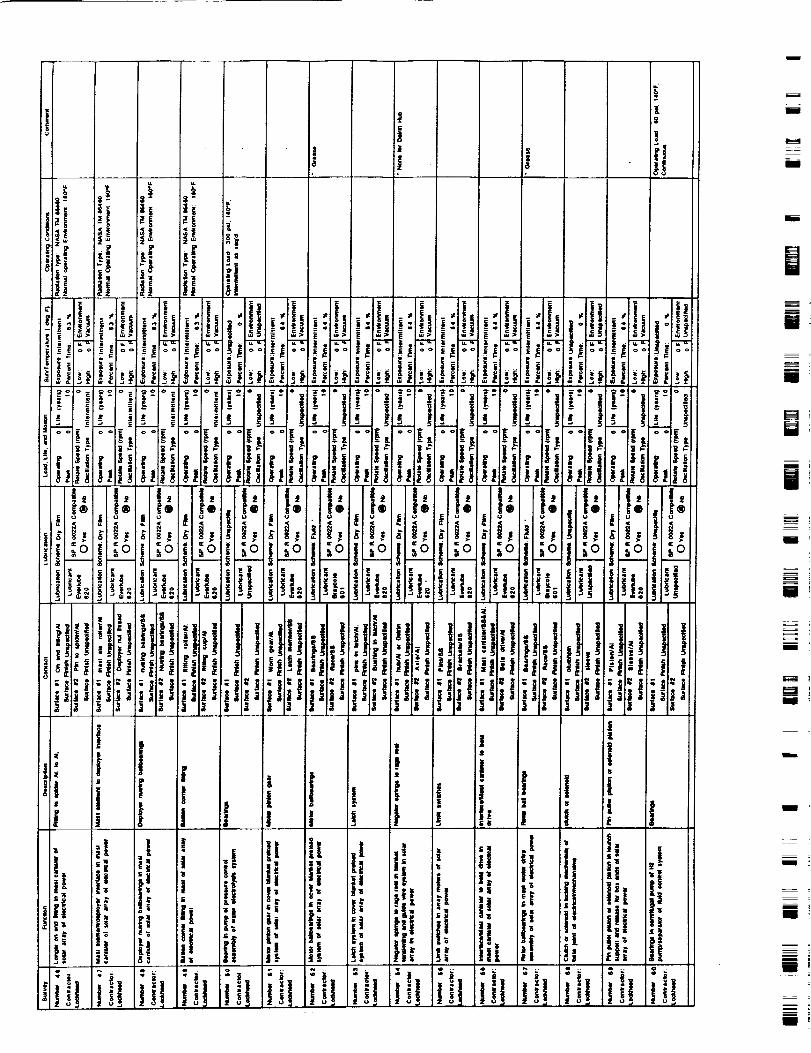
m
H
i'm
mi
W
[]
[]iW
m _
IB
m_
m
mlm _
U _
ml
mm _
mm_
m_m
mmm
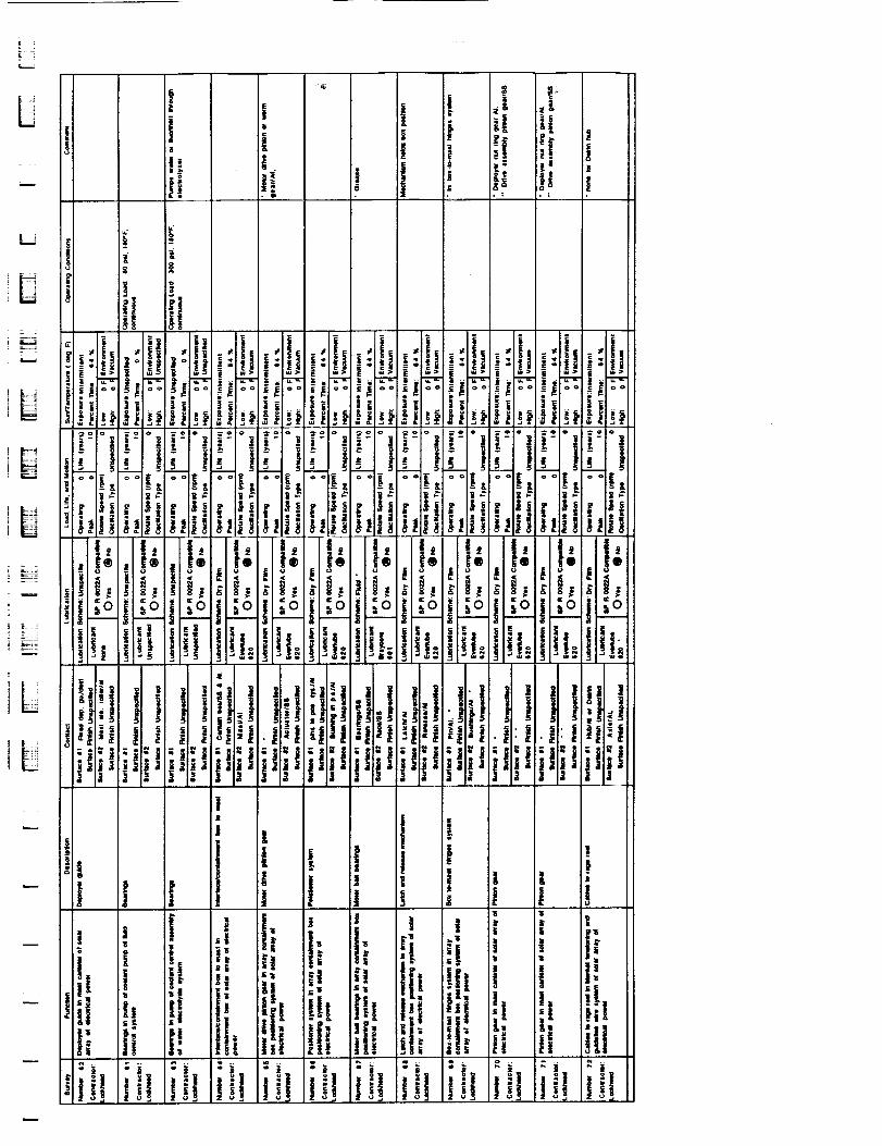
L,mJ
U
L
_j
imJ
,b
iLi
4.0 REFERENCES In
Dolan,-F., "Space Station Long Term Lubrication Studies Contract, 'Kickoff' _.
Meeting", Presentation Charts, National Aeronautics and Space
Administration, MSFC/EH14, August 1985.M
"Space Station Long Term Lubrication, Orientation Briefing" Presentation Charts,
Battelle Columbus Laboratories and SRS Technologies, August 28, 1985. m
"Space Station Reference Configuration Description", JSC-19989. i
"Space Station Subsystem White Papers", JSC-20054.
"General Specification Vacuum Stability Requirements of Polymeric Material for
Spacecraft Application", SP-R-0022A.
m
mmm
I
m
m
M
m
u
R
mI
!
m
40 l
m
u
Appendix A
Survey Forms
=
A-I
m_
IN
I
D
g
m I
ml
l
mIm
z
mmI
i
J
mR
mI
i
ID '
m
I
mmmmmm
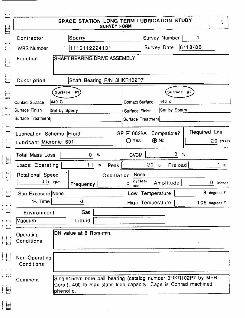
USPACE STATION LONG TERM LUBRICATION STUDY
SURVEY FORM
ri=..
Contractorr _
.._ WBS Number
ISperry
I1 11 61122241 31
Survey Number I 1
Survey Date 16/1 8/86
Function
SHAFT
BEARING DRIVE ASSEMBLY
_:_ Description IShaft Bearing P/N 3HKR102P7
Contact Surface
_2 Surface Finish
1440 C
tSet by Sperry
Contact Surface
Surface Finish
[440 c ]
ISet by Sperry
Surface Treatment[
Lubrication Scheme IFluid
Lubricant IMicronic 601
Surface Treatment[
SP R 0022A Compatible? Required Life
0 Yes (_) No 2 0 years
i [ J
iFiTotal Mass Loss I 0 %
Loads: Operating I 1 1 Ib
CVCMI o %_!,,11.
Peak[ 20 Ib Preload I 1 tb
Rotational Speed
I 0.5 rpm Frequency I
Oscillation INone
0 cycles/ Amplitude Isec
0 inches
Sun Exposure INone
% Time I 0
Low Temperature [
High Temperature I
8 degrees F
1 0 5 degrees F
Environment
_:_ Ivacuum Liquid I
Operating IDN value at 8 Rpm-min.Conditions INon-Operating
Conditions
Comment Single15mm bore ball bearing (catalog number 3HKR102P7 by MPB
Corp.). 400 Ib max static load capacity. Cage is Conrad machined
phenolic.
| |_:-
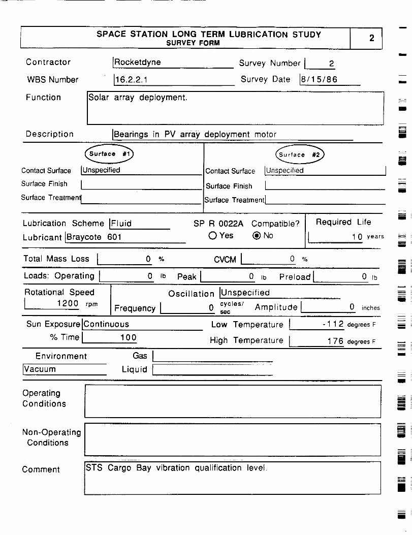
SPACE STATION LONG TERM LUBRICATION STUDYSURVEY FORM
2
Contractor
WBS Number
IRocketdyne
J16.2.2.i
Survey Number J 2
Survey Date [8/1 5/86m
m
Function
Solar array deployment.I
Description JBearings in PV array deployment motoru
B
Ill
Contact Surface IUnspecified
Surface Finish I
Surface Treatmenl I
Contact Surface Lunspecified
Surface Finish J
Surface TreatmentJ
Lubrication Scheme JFluid
Lubricant IBraycote 601
SP R 0022A Compatible?
J
Required Life
O Yes _) No 1 0 years
JI
u_m
mlid
mill
J
Total Mass Loss J 0 % CVCM I 0 %
Loads: Operating J 0 Ib PeakJ 0 Jb PreloadJ 0 Ib
Rotational Speed
J 1 200 rpmFrequency I
Oscillation IUnspecified
0 cycles/ Amplitude J,_BC
0 inches
m
I
Sun Exposure JContinuous
% Time J 1 0 0
Low Temperature l
High Temperature l
- 1 1 2 degrees F
1 7 6 degrees F
m
Environment
IVacuum
GasILiquid J
Iil
OperatingConditions
Non-OperatingConditions
STS Cargo Bay vibration qualification level.
m
ilm
I
Z
li
CommentII
il
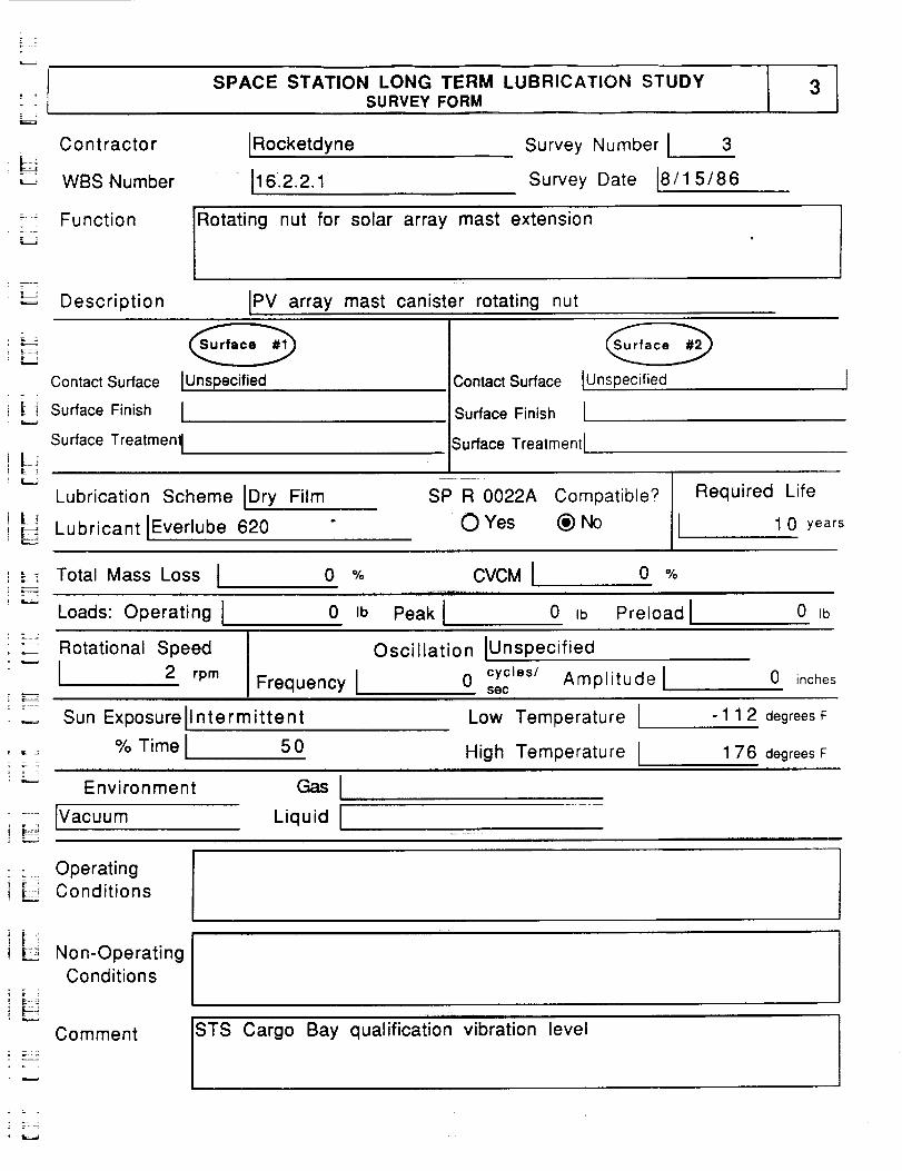
]
SPACE STATION LONG TERM LUBRICATION STUDYSURVEY FORM
= ,
Contractor
WBS Number
IRocketdyne
i16.2.2.1
Survey Number i 3
Survey Date i8/15/86
_÷ Function Rotating nut for solar array mast extension
_-.J Description IPV array mast canister rotating nut
L-
Contact Surface IUnspecified
- Surface Finish= =
Surface TreatmenlE _
[ []
Contact Surface IUnspecified
Surface Finish I
Surface Treatmenl I
Lubrication Scheme IDry Film
i _ Lubricant Everlube 620
SP R 0022A Compatible.'?
O Yes (_) No
Required Life
1 0 years
i _ Total Mass Loss I, = =
Loads: Operating I
0 % CVCM I 0 %
0 Ib Peak I 0 Ib Preload I 0 Ib
: _ _ Rotational Speed
"- i 2 rpm
=
Frequency I
Oscillation IUnspec ified
0 cycles/ Amplitudelsec
0 inches
Sun Exposurellntermittent Low Temperature
% Time I 50 High Temperature I
-1 1 2 degrees F
1 76 degreesF
Environment Gas I
.... IVacuu m Liquid I
STS Cargo Bay qualification vibration level
Operating
_ Conditions
, _ Non-Operating
Conditions
Comment
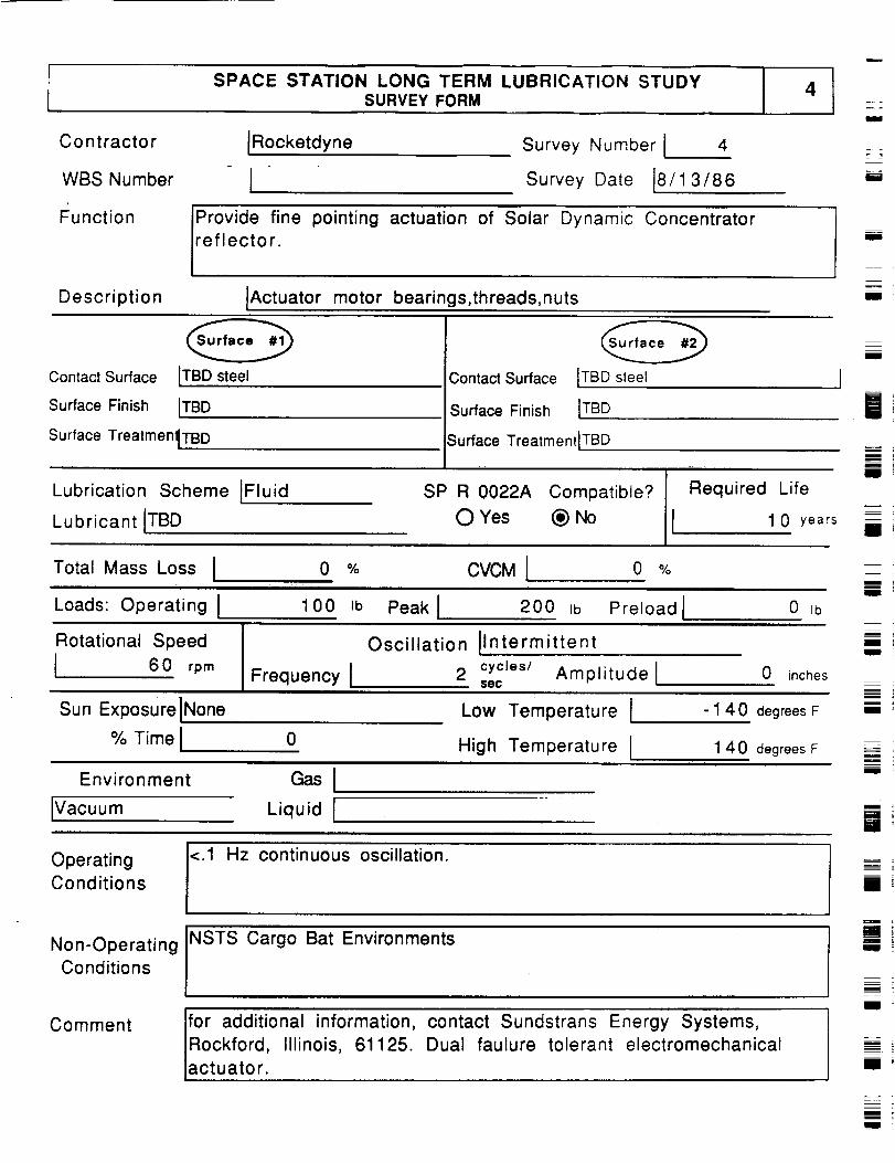
SPACE STATION LONG TERM LUBRICATION STUDYSURVEY FORM
IRocketdyneContractor
WBS Number I
Function IProvide fine pointing actuation of Solar Dynamic Concentrator
reflector.
Description IActuator motor bearings,threads,nuts
Survey Number I 4
Survey Date 18/1 3/86
i
i
m!
i
Contact Surface ITBD steel
Surface Finish ITBD
Surface TreatmentTBD
Lubrication Scheme IFluid
Lubricant ITBD
Contact Surface
Surface Finish ITBD
Surface TreatmentlTBD
[TBD sleel
SP R 0022A Compatible?
0 Yes (_) No
Required Life
I 1 0 years
m
!
J
m
R
BB
BB
Total Mass Loss I 0 % CVCM I 0 % u
I
Loads: Operating I 100 Ib Peakl 200 Ib Preload I 0 rb
Rotational Speed
I 6 0 rpmFrequency I
Oscillation Ilntermittent
2 cycles/ Amplitude l$ec
0 inches
Sun ExposurelNone Low Temperature I -1 40 degrees F
Emi
!
i
% Time I 0High Temperature I 1 40 degrees F
Environment
IVacuum Liquid I mlib
OperatingConditions
<l Hz continuous oscillation.
NSTS Cargo Bat EnvironmentsNon-OperatingConditions
i ;
Comment for additional information, contact Sundstrans Energy Systems,
Rockford, illinois, 61125. Dual faulure tolerant electromechanical
actuator.i ;
mI
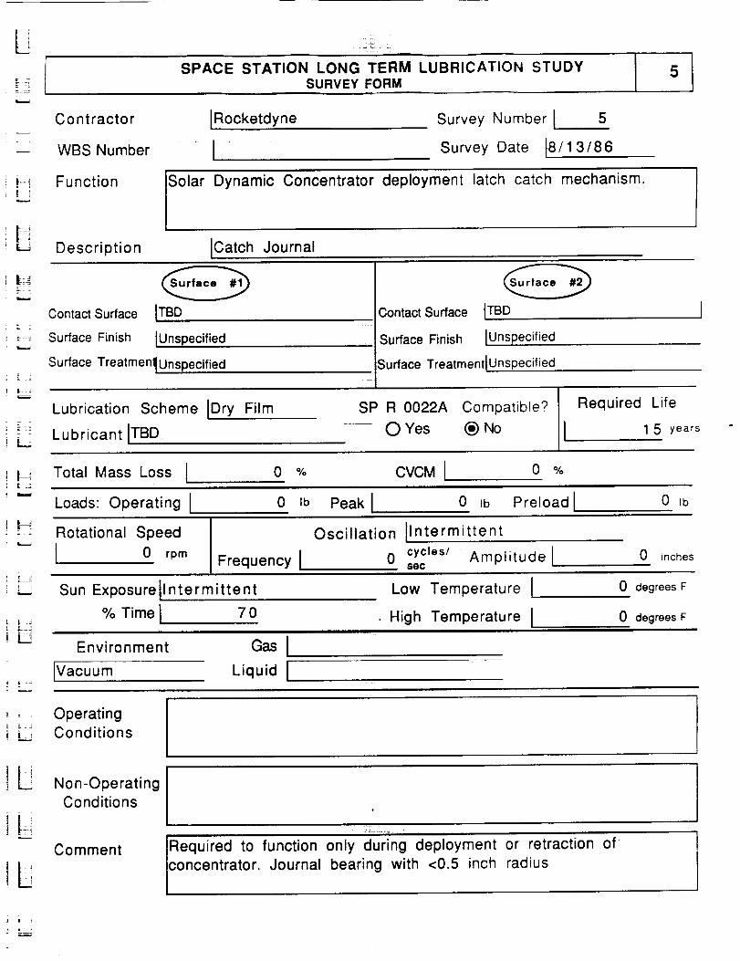
|L
SPACE STATION LONG TERM LUBRICATION STUDYSURVEY FORM
5
Contractor
--- WBS Number
IRocketdyne
ISurvey Number I 5
Survey Date t8/1 3/86
i:! Function Solar Dynamic Concentrator deployment latch catch mechanism.
ir_ ¸
' _ Description ICatch Journal
Contact Surface ITBD
:__ Surface Finish IUnspecified
Contact Surface
Surface Finish
LTBD
IUnspecified
Surface TreatmentiUnspecified
Lubrication Scheme [Dry Film
Lubricant ITBD
Surface Treatmenl IUnspecified
SP R 0022A Compatible?
O Yes (_) No
Required Life
I 1 5 years
Total Mass Loss I 0 % CVCM I 0 %
Loads: Operating I 0 Ib Peak I 0 ,b Preload I 0 ,b
Rotational Speed
I 0 rpm
Oscillation IIntermittent
Frequency I o secCyCles/Amplitude l 0 inches
Sun Exposurell ntermittent
% Time I 7 0
Environment GasIIVacuum Liquid I
Low Temperature IHigh Temperature 1
0 degrees F
0 degrees F
OperatingConditions
Non-OperatingConditions
Required to function only during deployment or retraction of
concentrator. Journal bearing with <0.5 inch radius
Comment
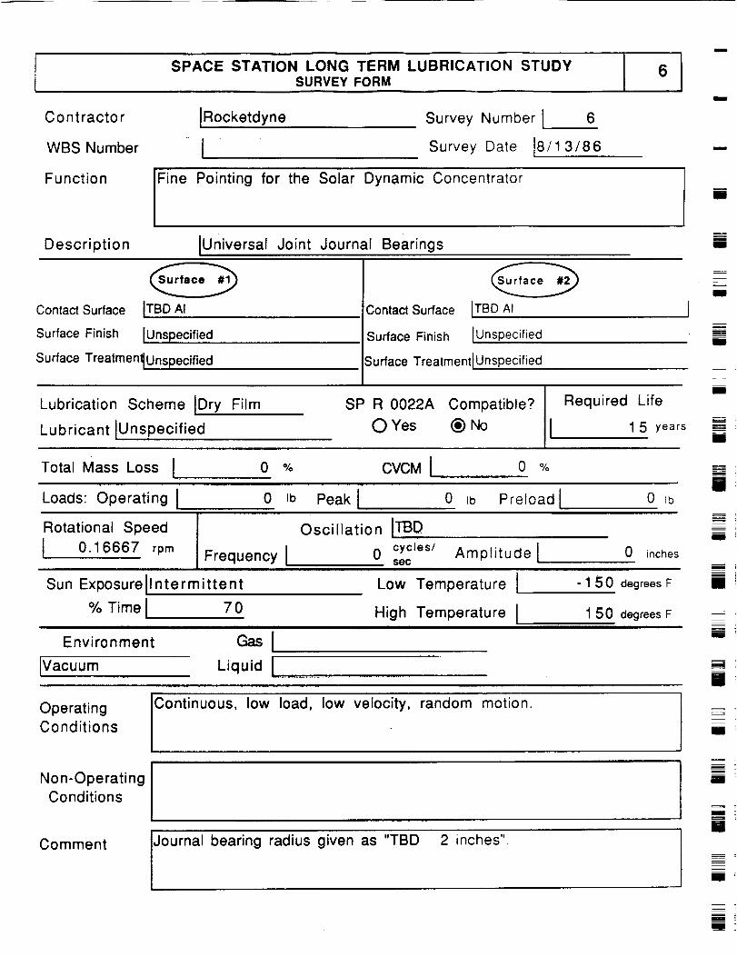
SPACE STATION LONG TERM LUBRICATION STUDYSURVEY FORM °1
Contractor
WBS Number
Function
IRocketdyne
1Survey Number [ 6
Survey Date 18/1 3/86
Fine Pointing for the Solar Dynamic Concentrator
m
m
li
Description IUniversal Joint Journal Bearings II
Contact Surface ITBD AI
Surface Finish IUnspecified
Contact Surface
Surface Finish
ITBD AI J
IUnspecified
Surface TreatmentlUnspecified Surface Treatment tUnspecified
Lubrication Scheme IDry Film
Lubricant IUnspecified
SP R 0022A Compatible?
O Yes (_) No
Required Life
1 5 years
ZEll
m
IB
Ill
m
II
Total Mass Loss I 0 % CVCMI....... o %
Loads: Operating ! 0 Ib Peak I 0 _b Preloadl 0 _b
Rotational Speed
I 0.16667 rpm Frequency I
Sun Exposurell ntermittent
% Time I 7 0
Environment _i
IVacuum
Oscillation ITBD0 cycles/ Amplitude I 0 inches
sec
Low Temperature I - 1 50 degreesF
High Temperature I _'150. degreesF
l
immEEl
Bli
Operating
Conditions
Continuous, low load, low velocity, random motion.
Journal bearing radius given as "TBD 2 inches".
Ill
Non-OperatingConditions
Comment
i
m
U
im

= ,
I SPACE STATION LONG TERM LUBRICATION STUDYSURVEY FORM
C o ntractor IRocketdyneT
,-- WBS Number
Survey Number I 7
Survey Date 18/1 3/86
_ _ Function IConcentrator
Reflector Deployment
Description IHinge Needle Bearing
L-J
Contact Surface ITBD
| i Surface Finish IUnspecified
Surface Treatmenl_ Unspecified
Lubrication Scheme IDry Film
_ Lubricant IUnspecified
Contact Surface ITBD
Surface Finish IUnsp ecified
;urface Treatment IUnspecified
SP R 0022A Compatible? Required Life
0 Yes _ No 1 5 years
Total Mass Loss I 0 % CVCM I 0 %
" _ Loads: Operating I 100 Ib Peak I 150 _b Preload I 0 Ib
Rotational Speed
[ 0.16667 rpm
Oscillation INone
Frequency I 0 secCyCleS/ Amplitude [ 0 inches
'Li
Sun Exposurell ntermittent
% Time I 7 0i i
Environment GasIIVacuum Liquid I
Low Temperature I
High Temperature I
-150 degreesF
150 degrees F
Operating
_ Conditions
Required to function only during deployment and retraction on-orbit.
Roller bearing
Non-Operating
Conditions
Comment

SPACE STATION LONG TERM LUBRICATION STUDYSURVEY FORM
Contractor
WBS Number
Function
Description
IRocketdyne Survey Number I 8
1 Survey Date 18/15/86
Cycle Solar Dynamic Power Generation
iAItenator foil journal and thrust bearings for the Closed Drayton
Power Conversion Unit.
IRotor/Housing Interface
i
im
m
II
II
Contact Surface
Surface Finish
Surface Treatmenl Unspecified
IRotor Journal Contact Surface
lUnspecified
Lubrication Scheme IFluid
IFoil Leaves
Surface Finish IUnspecified
Surface Treatment IUnspecified
SP R 0022A Compatible? Required Life
II
il
II
Lubricant IHelium/Xenon (MW=40) O Yes _) No I 3 0 yearsII
Total Mass Loss I o % CVCMI o %
Loads: Operating I 0 tb Peak I 0 Ib Preload I 0 _b
Rotational Speed
I 32000 rpm
Oscillation IContinuous
Frequency I 1060 secCyCles/ Amplitude I 0 inches
Sun Exposure None Low Temperature l 100 degrees F
% Time
Environment
0 High Temperature l 300 degrees F
Gas IHelium/Xenon (MW=40)
_= =
IPressurized Liquid I
Rotor lubricant inventory is approximately 4 Ibs of lubricant.
Operating load is given as "approximately 100 kW Shaft". Pressure in
housing is 20 to 60 psi.
Operating
Conditions
Non-Operating
Conditions
Comment IJournal Bearing with 2.726 inch radius operating at a 760 fps relative
velocity.Volatile fluid is contained in welded housing. Extreme
operating conditions may include temps -100 deg F to 400 deg F.
mw
=_
t
i
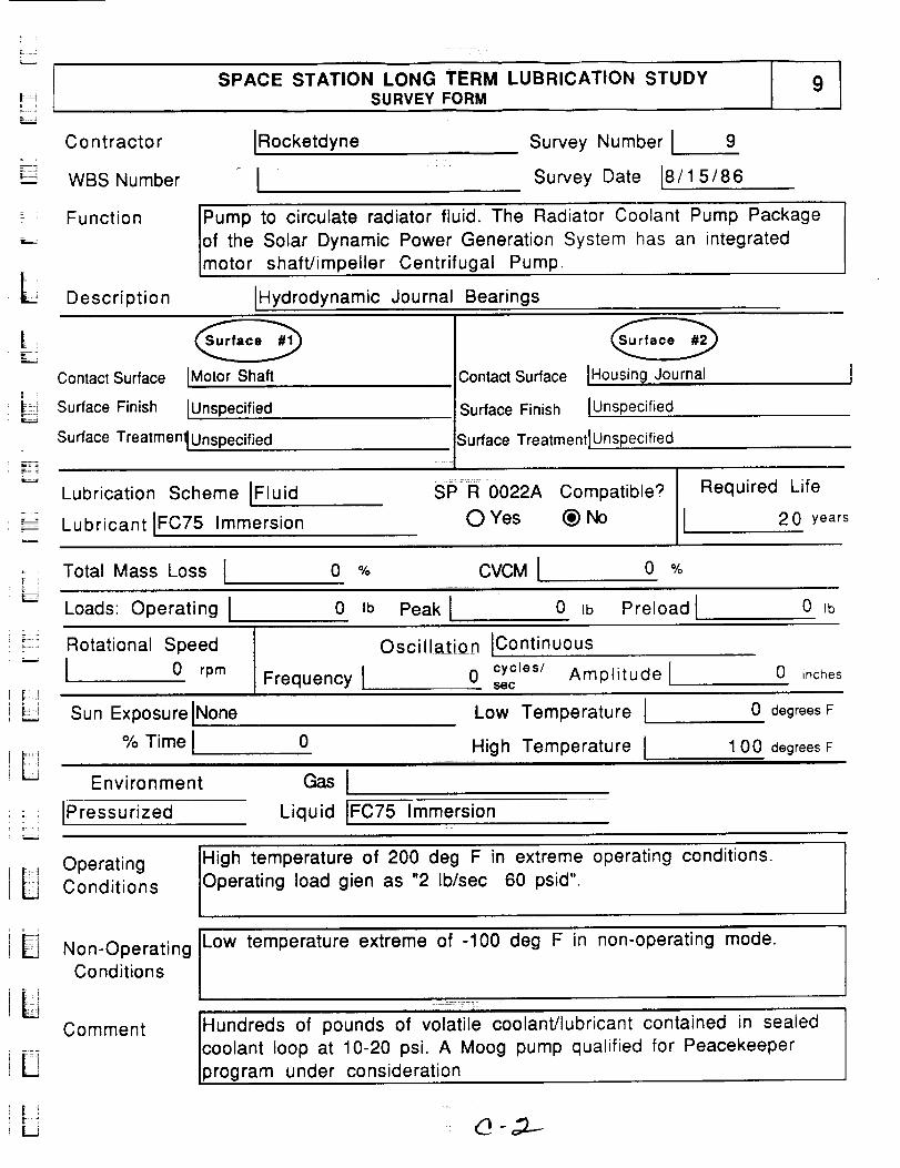
L
9SPACE STATION LONG TERM LUBRICATION STUDYSURVEY FORM
_=--Ez_
C o nt racto r [Rocketdyne
WBS Number [
Survey Number [ 9
Survey Date 18/15/86
L
Function IPump to circulate radiator fluid. The Radiator Coolant Pump Package
Iof the Solar Dynamic Power Generation System has an integratedImotor shaft/impeller Centrifugal Pump.
Description [Hydrodynamic Journal Bearings
F
E-Z
Contact Surface [Motor Shaft
Surface Finish [Unspecified
Surface Treatment[Unspecified
Lubrication Scheme [Fluid
Lubricant IFC75 Immersion
Contact Surface [Housing Journal
Surface Finish [Unspecified
Surface Treatment IUnspecified
SP R 0022A Compatible?
O Yes (_) No
Required Life
2 0 years
; ; Total Mass Loss [ 0 % CVCM I 0 %
4
Loads: Operating I 0 Ib Peak [ 0 Ib Preload I 0 Ib
;:::: Rotational Speed
w I 0 rpm Frequency I
Oscillation IContinuous
0 cycles/ Amplitude[sec
0 inches
! Sun Exposure INone
% Time I 0L
Environment GasI::i [Pressurized Liquid IFC75 Immersion
Low Temperature [
High Temperature [
0 degrees F
100 degrees F
, o , Operating
L Conditions
High temperature of 200 deg F in extreme operating conditions.
Operating load gien as "2 lb/sec 60 psid".
Low temperature extreme of -100 deg F in non-operating mode.
Hundreds of pounds of volatile coolant/lubricant contained in sealed
coolant loop at 10-20 psi. A Moog pump qualified for Peacekeeper
program under consideration
Non-OperatingConditions
Comment
i

SPACE STATION LONG TERM LUBRICATION STUDYSURVEY FORM
10
i
Contractor
WBS Number
Function
IRocketdyne Survey Number I 1 0
i Survey Date 18/4/86
To position the Propulsion System thruster assembly
when solenoid is not engaged.
Description Ends of spring at shaft and spring stop
solenoid valve
ill
[]i
i,,.
Contact Surface IUnspecified
Surface Finish IUnspecified
Surface TreatmenllUnspecified
Contact Surface IUnspecified
Surface Finish IUnspecified
Surface TreatmentlUnspecified
m
Ii
Lubrication Scheme IUnspecifie
Lubricant IUnspecified
SP R 0022A Compatible?
O Yes (_) No -
Required Life
0 years
i
Total Mass Loss I 0 % CVCM I 0 %
Loads: Operating I 0 Ib Peak I 0 Ib Preload I 0 ib
Rotational Speed
0 rpmFrequency I
Oscillation IUnspecified
0 cycles/ Amplitude lsec
0 inches
Low Temperature I
High Temperature Ii i i i J
i
Sun Exposure IUnspecified
% Time I 0irl i ir i i i
Environment Gas I
IUnspecified Liquid !
0 degrees F
0 degrees Fi
i
Operating
Conditions
Non-Operating
Conditions
Comment
m
U
[]
i

SPACE STATION LONG TERM LUBRICATION STUDYSURVEY FORM
C o n t racto r IRocketdyne
WBS Number I
Survey Number ! 1 1
Survey Date 8/5/86
-"-¢ 4
Function Fluid connector for Propuslion System thruster assembly.
Description IScrew threads on propellant feed lines
Contact Surface IMale connector
=__ Surface Finish IUnspecified
Surface Treatmen_Unspecified
Lubrication Scheme IUnspecifie
Lubricant IUnspecified
Contact Surface IFemale connector
Surface Finish IUnsp ecified
Surface TreatmenlJUnspecified
SP R 0022A Compatible?
O Yes (_) No
Required Life
I 0 years
Total Mass Loss I 0 % CVCMI 0 %
Loads: Operating I 0 Ib Peak i o ,b Preload I 0 tb
L .
_ Rotational Speed
"--" 0 rpmFrequency I
Oscillation IUnspec ified
0 cycles/ Amplitude[sgc
0 inches
i F
Sun Exposure IU nspecified
% Time I 0
Environment
21 IUnsp ecified
Gas l
Liquid [
Low Temperature I
. High Temperature 1: J rUlllnl
0 degrees F
0 degrees F
OperatingConditions
Non-OperatingConditions
Comment
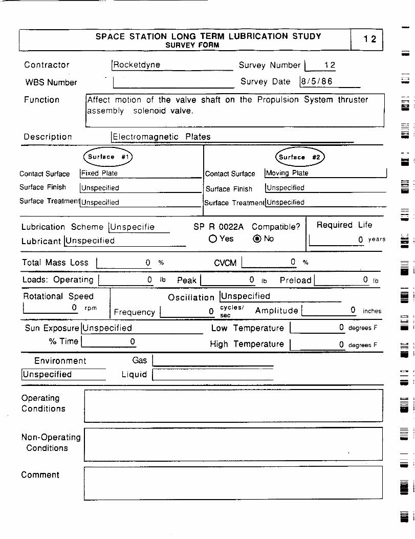
SPACE STATION LONG TERM LUBRICATION STUDYSURVEY FORM
IRocketdyne
ISurvey Number i 12
Survey Date i8/5/86
Contractor
WBS Number
Function JAffect motion of the valve shaft on the Propulsion System thruster
assembly solenoid valve.
Description IElectromagnetic Plates
I
M
u
L_
i
I '
Contact Surface IFixed Plate
Surface Finish [Unspecified
Surface Treatment_Unspecified
Contact Surface iMoving Plate
Surface Finish IUnspecified
Surface TreatmentlU nspecified
i
m
Lubrication Scheme lUnspecifie
Lubricant iUnspecified
SP R 0022A Compatible?
0 Yes (_) No
Required Life
i 0 years
i '
Total Mass Loss I 0 % CVCM I 0 %r
Loads: Operating I 0 Jb Peak I 0 =b Preload I 0 Ib
B
mi
Rotational Speed
I 0 rpm Frequency i
Oscillation IUnspecified
0 cyctes/ Amplitude lsec
0 inches
Sun Exposure IU nspecified Low Temperature i 0 degrees F
I
i
% Time 1
Environment
IUnspecified
0
Gas I
Liquid I
High Temperature I 0 degrees Flatt i n t i i i
m
m
I
OperatingConditions m
I
Non-OperatingConditions
Comment
mm
i
mi
i
mi
M
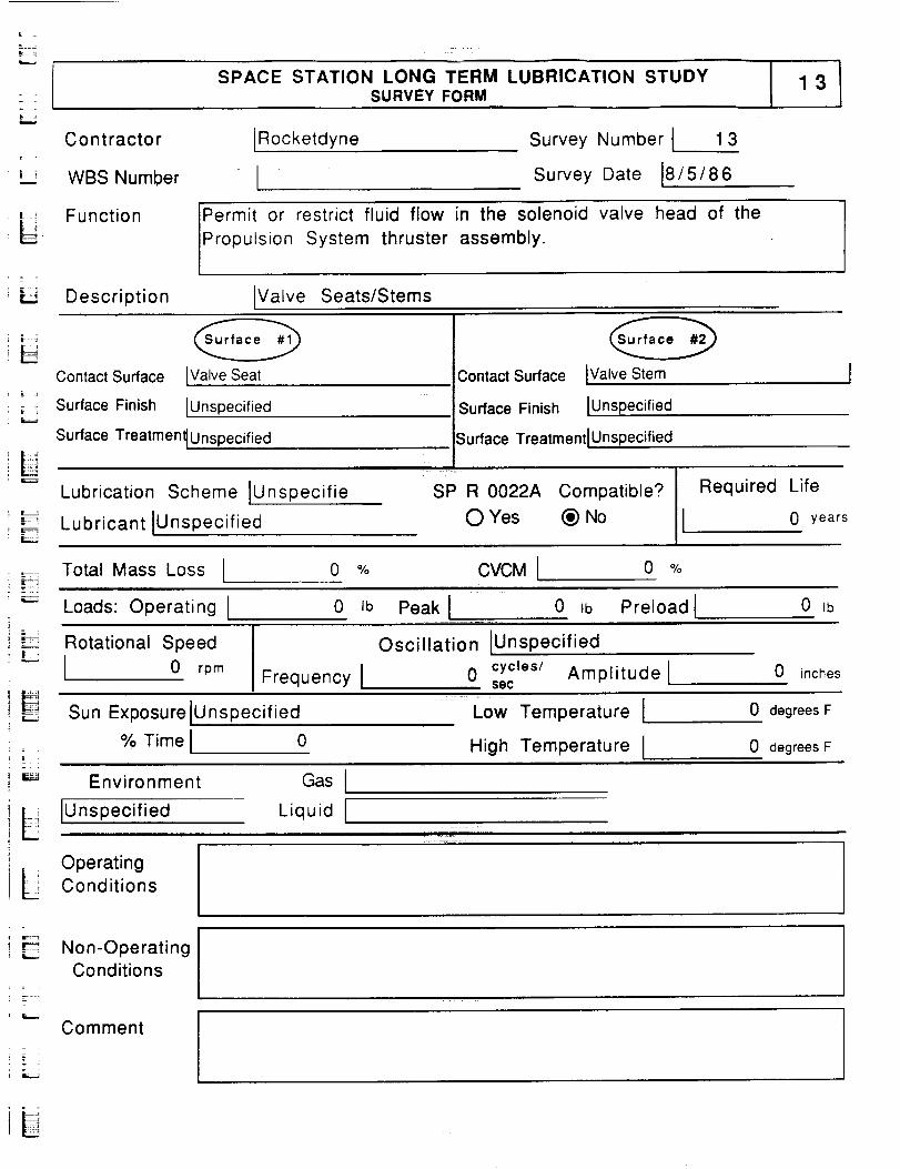
= =
SPACE STATION LONG TERM LUBRICATION STUDYSURVEY FORM
13
L_
Contractor
WBS Number
Function
[Rocketdyne Survey Number [ 1 3
Survey Date 18/5/86
Permit or restrict fluid flow in the solenoid valve head
Propu s on System thruster assembly.
of the
i 3
Description IValve Seats/Stems
Contact Surface [Valve Seat
Surface Finish [Unspecified
Surface Treatment IUnspecified
Lubrication Scheme IUnspecifie
Lubricant IUnspecified
Contact Surface IValve Stem
Surface Finish [Unspecified
Surface Treatment[ Unspecified
SP R 0022A Compatible?
O Yes (_ No
Required Life
0 years
Total Mass Loss 0 % CVCM I 0 %
i =
Loads: Operating I
Rotational Speed
I 0 rpm
0 Ib
Frequency I
Peak [ 0 Ib Preload 1
Oscillation [Unspec ified
0 cycles/ Amplitude lsec
0 Ib
0 inches
Sun Exposure IU nspecified
% Time [ 0
Low Temperature I
High Temperature I
0 degrees F
0 degrees F
: = := =
i _ Environment
il L IUnspecified
Gas[
Liquid I
i Operating
L Conditions
Non-OperatingConditions
Comment
iU
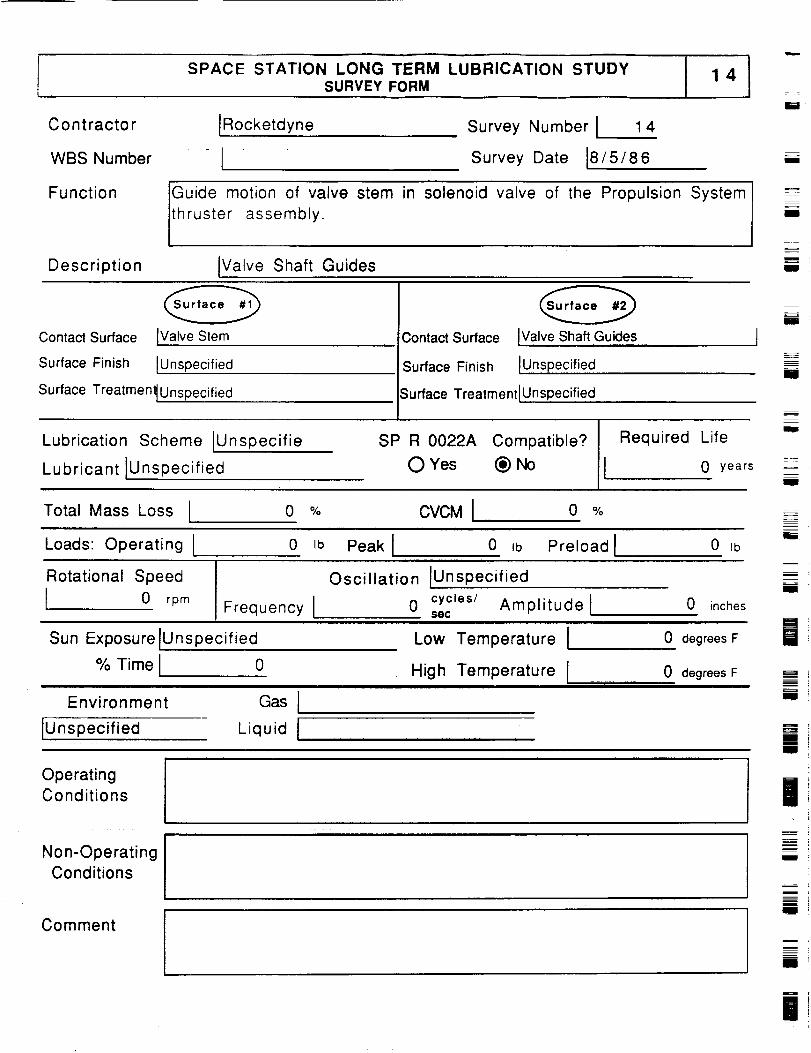
SPACE STATION LONG TERM LUBRICATION STUDYSURVEY FORM
14
Contractor
WBS Number
Function
Description
IRocketdyne
ISurvey Number I 1 4
Survey Date 18/5/86
Guide motion of valve stem
thruster assembly.
in solenoid valve of the Propulsion System
IValve Shaft Guides
i
i
I
I
Contact Surface IValve Stem
Surface Finish IUnspecified
Surface Treatment_Unspecified
Contact Surface [Valve Shaft Guides
Surface Finish IUnspecified
Surface Treatment IUnspecified
i
i
=
R
Lubrication Scheme IUnspecifie
Lubricant IUnspecified
SP R 0022A Compatible?
O Yes (_) No
Required Life
I 0 years m
g
Total Mass Loss I 0 % CVCMI 0 =/o
Loads: Operating I 0 Ib Peak I 0 lb Preload I 0 lb
m
Rotational Speed
I 0 rpm Frequency I
Oscillation IUnspecified
0 cycles/ Amplitude lsec
0 inches
Sun Exposure IUnspecified Low Temperature I 0 degrees F
m
m
Rl
% TimeI 0
Environment
Iunspecified
Gas I
Liquid I
High Temperature [ 0 degrees F
i
OperatingConditions
Non-OperatingConditions
Comment
iiI
!
i i
m
m
I
i1

t SPACE STATION LONG TERM LUBRICATION STUDY 1 5i_ SURVEY FORM
C o n t racto r JRocketdyne
WBS Number J
Survey Number I 1 5
Survey Date J00/00/00
Function JTo form a connection between tubing and the dummy spark igniter in
Ithe Propulsion SYstem thruster assembly.
Description JDummy spark igniter/tubing connection
U
L
[Tygon tubingContact Surface
Surface Finish [Unspecified
Surface Treatmen_ Unspecified
Contact Surface IDummy Spark Igniter
Surface Finish JUnspecified
Surface TreatmentJ Unspecified
Lubrication Scheme Lunspecifie
Lubricant JUnspecified
SP R 0022A Compatible?
O Yes (_ No
Required Life
0 years
Total Mass Loss I
Loads: Operating I
0 %
0 lb
CVCMI 0 O,oPeakJ 0 Ib Preload[ 0 Ib
= =
Rotational Speed
I 0 rpmFrequency I
Oscillation IUnspecified
0 cycles/ Amplitude l86C
0 inches
Low Temperature 1
High Temperature J
j _iliJ,L Sun Exposure tUnspecified
% Time I 0
Environment
IUnspecified
Gas J
Liquid I
0 degrees F
0 degrees F
! "-c::z
Operating
i L Conditions
, F_ Non-OperatingConditions
J L _"
_. L.,
Comment

SPACE STATION LONG TERM LUBRICATION STUDYSURVEY FORM
Contractor
WBS Number I
IRocketdyne Survey Number i 1 6
Survey Date 18/5/86
I
gm
m
Function hardare attachment device. Hex head bolt asembly in the valve bracket
assembly of the Propulsion SYstem thruster assembly.
Description IScrew threads/bolt
mi
_MI
Contact Surface IScrew threads
Surface Finish I
Surface Treatmen_
ContactSurface
Surface Finish
IHex head bolt I
IUnspecified
Surface Treatment IUnspecified
mI
m
Lubrication Scheme IFluid
Lubricant IMoS2
I
SP R 0022A Compatible? iII Required LifeO Yes @ NO 0 years
Total Mass Loss I 0 % CVCM I 0 %
i
I
Loads: Operating I 0 Ib Peak I 0 Ib Preload I 0 _bi
Rotational Speed
I 0 rpmFrequency I
Oscillation IUnspecified
0 cycles/ Amplitude lsec
0 inches
[]
m
t
Sun Exposure IUnspecified
% Time I 0
Environment
IUnspecified
Gas I
Liquid I
Low Temperature I
High Temperature I1 f .i : .i .| ii i! . i J
0 degrees F
0 degrees F
I
i
i ;
OperatingConditions
m
M
Non-OperatingConditions
m ]
M
Commenti ;
____==i
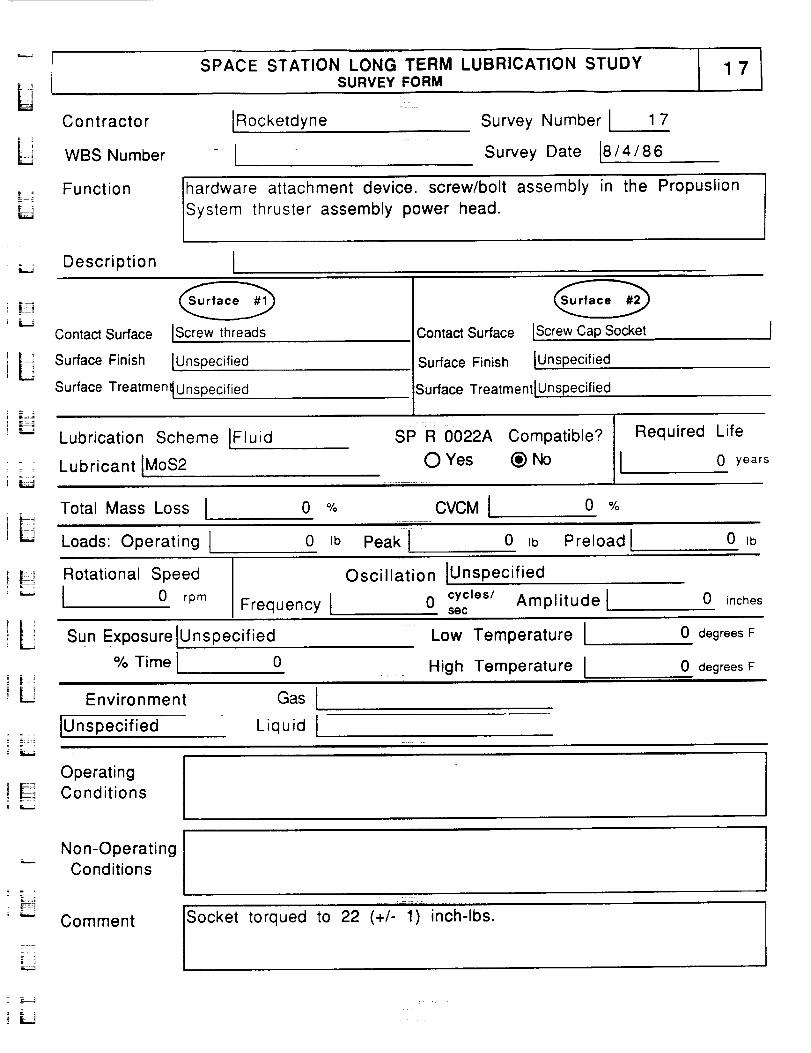
SPACE STATION LONG TERM LUBRICATION STUDYSURVEY FORM
Contractor
WBS Number
[Rocketdyne
[Survey Number I 17
Survey Date [8/4/86
Function hardware attachment device, screw/bolt assembly
System thruster assembly power head.
in the Propuslion
LJ Description I
L
- .
Contact Surface IScrewthreads
Surface Finish IUnspecified
Surface Treatmen_ Unspecified
Contact Surface IScrew Cap Socket
Surface Finish IUnspecified
Surface Treatment IUnspecified
Lubrication Scheme IFluid
Lubricant IMoS2
: I|
SP R 0022A Compatible? I Required LifeOYes (_)No I 0 years
Total Mass Loss I 0 °_o CVCMI 0 O_o
f _ Loads: Operating [ 0 Ib Peakl o ,b Preloadl 0 ,b
! !_i Rotational Speed
I 0 rpm
Oscillation IUnspec ified
Frequency I 0 cyc=es/secAmplitude l 0 inches
L Sun ExposurelUnspecified :_ Low Temperature I 0 degrees F
% Time I 0 High Temperature I 0 degrees F
Environment Gas I
: _:; lUnsp ecified Liquid I
Operating
! _! Conditions
Non-OperatingConditions
Comment to 22 (+/- 1)inch-lbs.
Socket torqued
:- =

i_i
i
i
[]
R
__
ii
i
i
i
--_'_-
i
__
i !
i!
i
i!
i!
--
i!
n_nm!
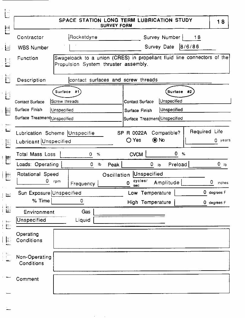
l .
SPACE STATION LONG TERM LUBRICATION STUDYSURVEY FORM
C o ntracto r [Rocketdyne
_=_ WBS NumberL.'
Survey Number I 1 8
Survey Date 18/6/86
Function Swageloack to a union (CRES) in propellant fluid
Propulsion System thruster assembly.line connectors of the I
Description lcontact surfaces and screw threads
LContact Surface lScrew threads
_ Surface Finish [Unspecified
, i ....
Contact Surface
Surface Finish
IUnspecified
[Unspecified
Surface Treatment[Unspecifie d Surface TreatmentlUnspecified
Lubrication Scheme IUnspecifie
Lubricant IUnspecified
SP R 0022A Compatible? Required Life
0 Yes (_) No 0 years
Total Mass Loss I 0 %I
F r_-
CVCMI 0 %
: _ Loads: Operating I 0 =b Peak I 0 ib Preload I 0 Ib
! L:
= #, Rotational Speed
! _" I 0 rpm Frequency I
Oscillation IUnspec ified
0 cycles/ Amplitude !$ec
0 inches
Sun Exposure IUnspecified
% Time I 0
Environment
IUnspecified
Gas !
Liquid I
Low Temperature I
High Temperature I
0 degrees F
0 degrees F
Operatingi _ Conditions
c
.... Non-Operating
Conditions
Comment
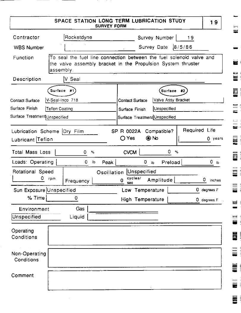
SPACE STATION LONG TERM LUBRICATION STUDYSURVEY FORM
Contractor
WBS Number
Function
lRocketdyne Survey Number I 1 9
I Survey Date 18/5/86
the valve assembly bracket in the Propulsion Systemassembly.
_o seal the fuel line connection between the fuel solenoid valve and
thruster
Description IV Seal
L==_li
m
Contact Surface IV-Seal-lnco 718
Surface Finish ITeflon Coating
Surface Treatmen_Unspecified
Contact Surface tValve Assy Bracket
Surface Finish IUnspecified
Surface TreatmentlUnspecified
===_,
i
Lubrication Scheme Dry Film
Lubricant ITeflon
SP R 0022A Compatible?
O Yes (_) No
Required Life
I 0 years
Total Mass Loss I
Loads: Operating I
o % CVCMI o %
0 Ib Peak I 0 Ib Preload I 0 Ib
Rotational Speed
I 0 rpm Frequency I
Oscillation IUnspec ified
0 cycles/ Amplitude lsec
0 inches
Sun Exposure IUnspecified
% Time I 0
Low Temperature
High Temperature I
0 degrees F
0 degrees F
Z
M
zm
i
Environment
[Unspecified
Gas I
Liquid I
Operating
Conditions
Non-Operating
Conditions
Comment
m
m!i
m
pR
! tm
m
m .
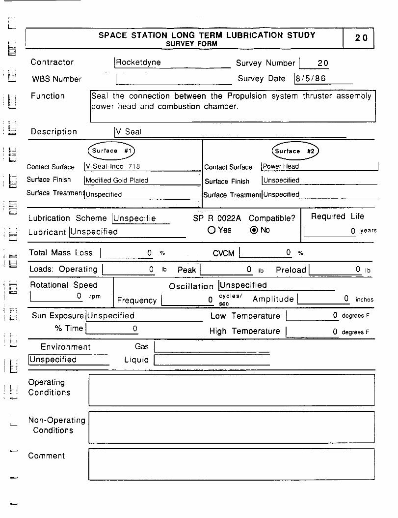
SPACE STATION LONG TERM LUBRICATION STUDYSURVEY FORM
20
Co ntracto r IRocketdyne"= i
: = =
-_ ! WBS Number ISurvey Number I 20
Survey Date [8/5/86
_ Function
Description IV Seal
Seal the connection between the Propulsion
power head and combustion chamber.
system thruster assembly
Contact Surface IV-Seal-lnco 718
i i-,_j Surface Finish IModified Gold Plated
Surface Treatment_Unspecifie d
Contact Surface IPowerHead
Surface Finish [Unspecified
Surface Treatment IUnspecified
- i
Lubrication Scheme IUnspecifie
Lubricant IUnspecified
SP R 0022A Compatible?
O Yes (_) No
Required Life
t 0 years
Total Mass Loss i 0 % CVCM I 0 %
Loads: Operating I 0 Ib Peak I.... 0 ,b Preload I 0 Ib
_:_ Rotational Speed
"" 0 rpmFrequency I
Oscillation IUnspecified
0 cycles/ Amplitudelsec
0 inches
Sun Exposure Iunspecified
% Time I 0
Low Temperature I
High Temperature I
0 degrees F
0 degrees F
LEnvironment
IUnspecified
Gas I
Liquid I:j_ _
OperatingConditions
Non-OperatingConditions
Comment
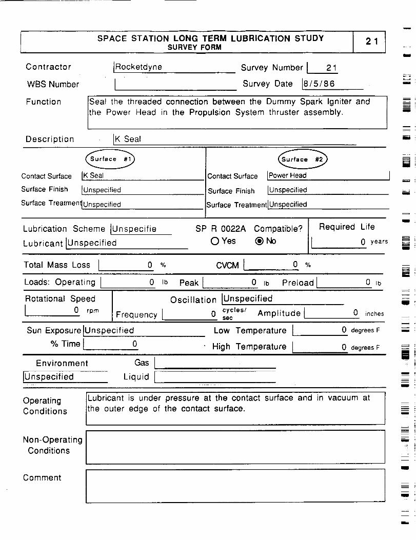
SPACE STATION LONG TERM LUBRICATION STUDYSURVEY FORM
21
Contractor
WBS Number
Function
Description
Rocketdyne
ISurvey Number I 21
Survey Date 18/5/86
Seal the threaded connection between the Dummy Spark Igniter and
the Power Head in the Propulsion System thruster assembly.
IK Seal
il
m
JiIIII
i
Contact Surface
Surface Finish
IK Seal
IUnspecified
Contact Surface [Power Head J
Surface Finish IUnspec flied
Surface Treatmen_Unspecified
Lubrication Scheme IUnspecifie
Lubricant IUnspecified
Surface Treatment IUnspecified
I
SP R 0022A Compatible? !II Required LifeO Yes @ NO 0 years
[]
zI
Illl
mi
Total Mass Loss l 0 %
Loads: Operating I 0 Ib
CVCMI o %i i i ii i ii i ii iii i i i ii
Peak I 0 Ib Preload I 0 Ib
W_
Rotational Speed
I 0 rpmFrequency I
Oscillation iUnspecified
0 cycles/ Amplitude lsec
0 inches
i :
Sun Exposure iUnspecified
% Time I 0i i mr i n iBm inili ilia lie I
Environment Gas l
iUnspecified Liquid I
Low Temperature I
High Temperature t
0 degrees F
0 degrees F
m ;
n
mi
OperatingConditions
Non-Operating
Conditions
Lubricant is under pressure at the contact surface and in vacuum at
the outer edge of the contact surface.m
ml
Commentz
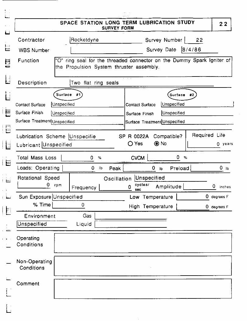
SPACE STATION LONG TERM LUBRICATION STUDYSURVEY FORM
L _Co nt ractor Rocketdyne
WBS Number I
Survey Number I 22
Survey Date 18/4/86
= =
t_= =
E _
Function I"O" ring seal for the threaded connector on the Dummy Spark Igniter of
the Propulsion System thruster assembly.
Description Two flat ring seals
i===i
Contact Surface
Surface Finish IUnspecified
Surface Treatmen_Unspecified
IUnspecified Contact Surface IUnspecified
Surface Finish IUnspecified
Surface Treatment IUnspecified
= .
= _
Lubrication Scheme [Unspecifie
Lubricant JUnspecified
SP R 0022A Compatible?
O Yes (_) No
Required Life
0 years
= Total Mass Loss I
Loads: Operating[
0 % CVCMI 0 %
0 Ib Peak [- 0 ,b Preload I 0 Ib
.... Rotational Speed
I 0 rpmFrequency I
Oscillation [Unspecified
0 cycles/ Amplitude lsec
0 inches
Sun Exposure IUnspecified
% Time I 0
Low Temperature I
High Temperature I
0 degrees F
0 degrees F
Environment
IUnspecified
Gas
Liquid [
. , OperatingConditions
Non-OperatingConditions
;_.,.
Comment
L
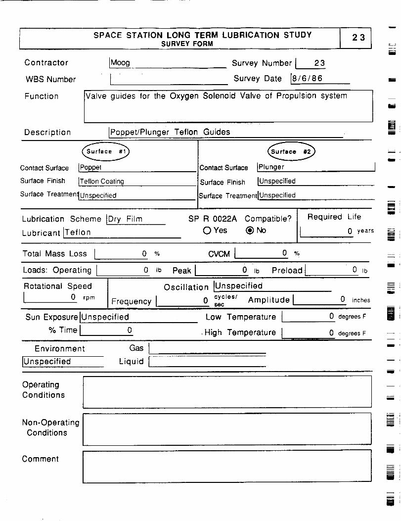
SPACE STATION LONG TERM LUBRICATION STUDY
Contractor IMoog
WBS Number I
SURVEY FORM
Survey Number i 23
Survey Date 18/6/86
i
mm
Function Valve guides for the Oxygen Solenoid Valve of Propulsion system
Description [Poppet/Plunger Teflon Guides
i
[]mU
Contact Surface IPoppet
Surface Finish ITeflon Coating
Surface Treatment_un specified
Contact Surface IP!unger
Surface Finish IUnspecified
Surface TreatmentlUn specified
m
m
mm
Lubrication Scheme IDry Film
Lubricant [Teflon
SP R 0022A Compatible?
O Yes (_) No
Required Life
0 years
g =
mBg
Total Mass Loss I 0 % CVCM I 0 O,'o
Loads: Operating I 0 Ib Peak J 0 =b Preload I 0 Ib
Rotational Speed
J 0 rpm Frequency I
Sun ExP0sureiunspecified
% Time I 0
Oscillation IUnspecified
0 cycles/ Amplitudelsec
Low Temperature 1
,High Temperature I
0 inches
0 degrees F
0 degrees F
m
i
lM
Environment
IUnspecified
Gas I
Liquid I
n
OperatingConditions
Non-OperatingConditions
lComment
m i
m_=_
[]
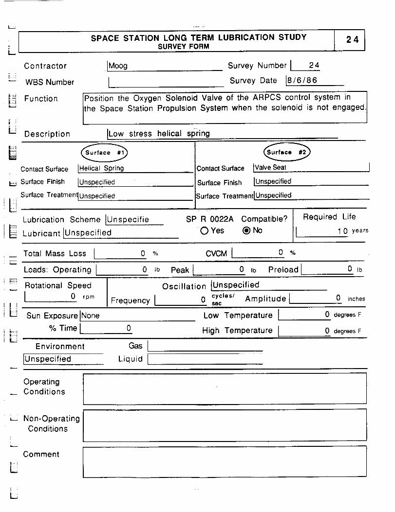
LSPACE STATION LONG TERM LUBRICATION STUDY
SURVEY FORM24
_ _ Contractor .[M°°g
WBS Number
Survey Number I 24
Survey Date [8/6/86
_ Function IPosition the Oxygen Solenoid Valve of the ARPCS control system in
'_ _ 'lthe Space Station Propulsion System when the solenoid is not engaged
_JDescription ILowstress helical spnng
Contact Surface2 .
Surface Finish
IHelicat Spring
IUnspecified
Surface Treatmen_Unspecified
Lubrication Scheme IUnspecifie
Lubricant IUnspecified
.3ontactSurface IValveSeat
Surface Finish IUnspecified
Surface TreatmentlUnspecified
SP R 0022A Compatible?
--O Yes (_)No
Required Life
1 0 years
Total Mass Loss I 0 % CVCM I 0 %
Loads: Operating [ 0 Jb Peakl 0 Ib Preload[ 0 Ib
L
Rotational Speed
I 0 rpmFrequency I
Oscillation IUnsp ecified
0 cycles/ Amplitude l800
0 inches
Sun Exposure INone Low Temperature I 0 degrees F
% Time I 0High Temperature I 0 degrees F
Environment
IUnspecified
Gas I
Liquid I
OperatingConditions
Non-OperatingConditions
Comment
L
l :
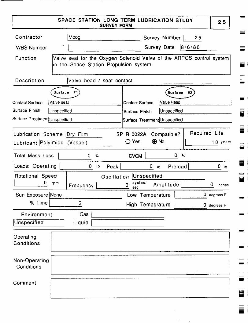
SPACE STATION LONG TERM LUBRICATION STUDYSURVEY FORM
i
IMoog
ISurvey Number I 25
Survey Date J8/6/86
Contractor
WBS Number
Function Valve seat for the Oxygen Solenoid Valve of the ARPCS control system
n the Space Station Propulsion system.
Description IValve head / seat contact
m
i
i
Contact Surface
Surface Finish
[Valve seat
[Unspecified
Contact Surface
Surface Finish
IValve Head
IUnspecified
surface Treatment{Unspecified
Lubrication Scheme [Dry Film
Lubricant IPolyimide (Vespel)
Surface Treatment I Unspecified
SP R 0022A Compatible?
O Yes _) No
Required Life
I 1 0 years
i
[]
m !m
Total Mass Loss I o % CVCMI o %ut
Loads: Operating I 0 Ib Peak I 0 Jb Preload I 0 Jb
Rotational Speed
I 0 rpmFrequency I
Oscillation tUnspecified
0 cycles/ Amplitude8ec
0 inches[]
Sun Exposure INone
% TimeI 0
Low Temperature I
High Temperature I
0 degrees F
0 degrees F
i t
Environment
IUnspecified
Gas I
Liquid I
Operating
Conditions
Non-Operating
Conditions
Comment
m
i
m_m_
m
i
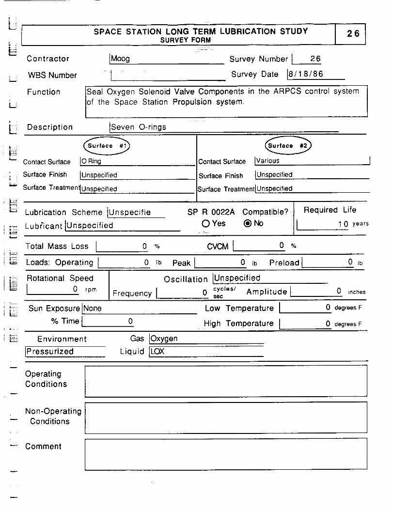
LSPACE STATION LONG TERM LUBRICATION STUDY
I 26SURVEY FORM
"_ Contractor IMoog
j WBS Number I
Survey Number I 26
Survey Date 18/1 8/86
Function Seal Oxygen Solenoid Valve Components in the ARPCS control system
of the Space Station Propulsion system.
Description ISeven O-rings
Contact Surface IO Ring
; • Surface Finish IUnspecified
"-" Surface Treatmen_Unspecified
Contact Surface
Surface Finish
IVarious
IUnspecified
Surface Treatment IUnspecified
Lubrication Scheme IUnspecifie
Lubficant IUnspecified
SP R 0022A Compatible? Required
O Yes (_) No
Life
1 0 years
Total Mass Loss I 0 % CVCMI 0 %
Loads: erating 0 Ib Peak ! 0 Ib Preload I 0 Ib
} _ Rotational Speed_ f..._ I 0 rpm Frequency I
Oscillation IUnspec ified
0 cycles/ Amplitude tsec
0 inches
.... Sun Exposure
% Time
None
0
Low Temperature I
High Temperature I
0 degrees F
0 degrees F
: :°:_ Environment
IPressurized
Gas Oxygen
Liquid ILOX
OperatingConditions
Non-Operating"- Conditions
=
Comment
w
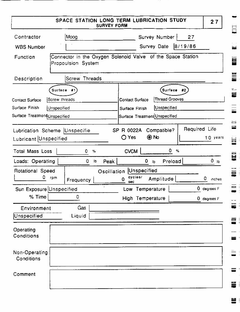
SPACE STATION LONG TERM LUBRICATION STUDYSURVEY FORM
I
C o n t racto r [Moog
WBS Number [
Survey Number I 27
Survey Date 18/19/86 I
Function Connector in the Oxygen Solenoid Valve of the Space Station
_Propoulsion System
Description [Screw Threads
i
iiI
Contact Surface lScrew threads
Surface Finish IUnspecified
Surface Treatmen_ Unspecified
Contact Surface IThreadGrooves
Surface Finish IUnspecified
Surface TreatmentlUnspecified
I
II
Lubrication Scheme lUnspecifie
Lubricant IUnspecified
SP R 0022A Compatible?
0 Yes (_) No
Required Life
I 1 0 years
I
I
Total Mass Loss I
Loads: Operating I
o % CVCMI 0 %i
0 Ib Peak I 0 Ib Preload I 0 Ib
L_
H
ill
Rotational Speed
I 0 rpmFrequency I
Oscillation IUnspecified
0 cycles/ Amplitude 1so(:
0 inches
u
li
Sun Exposure IUnspecified
% Time I 0
Low Temperature I
High Temperature I
0 degrees F
0 degrees F
ill
Environment Gas I
IUnspecified Liquid I __
OperatingConditions
li
rl
iI
INon-Operating
Conditions
CommentI
i
Ill
m
II

SPACE STATION LONG TERM LUBRICATION STUDYSURVEY FORM
- IM"_ Contractor oog
--: ' WBS I, Number= ::
Survey Number l 28
Survey Date 8/15/86
LFunction O-Ring seal between latching mechanism casing and plunger
mechanism of the Oxygen and Nitrogen Latching Valve in th ARPCS
Control System of the Space Station Propulsion System
Description 10- ring seal
L4
Contact Surface ICasing mechanism
IUnspecified
Surface Treatment_Unspecified
"-_' Surface Finish
Contact Surface IPlunger mechanism
Surface Finish IUnspec ified
Surface Treatment lunspecified
kLubrication Scheme IUnspecifie
Lubricant IUnspecified
SP R 0022A Compatible?
O Yes (_) No -
Required Life
I 1 0 years
Total Mass Loss I 0 % CVCMI 0
;_' Loads" Operating I 0 Ib Peak i......... 0 Ib Preload I 0 lb
_:_ Rotational Speed
i _" _ [ 0 rpmFrequency [
Oscillation IUnspec ified
0 cycaes/ Amplitude lsec
0 inches
L Sun Exposure INone% Time I 0
Low Temperature I
.High Temperature I
0 degrees F
0 degrees F
_ L Environment
i [ :, IPressurized
Gas I
Liquid Iiii
Operating
o_ Conditions
.... Non-Operating
Conditions
i L:iComment
x F,=:
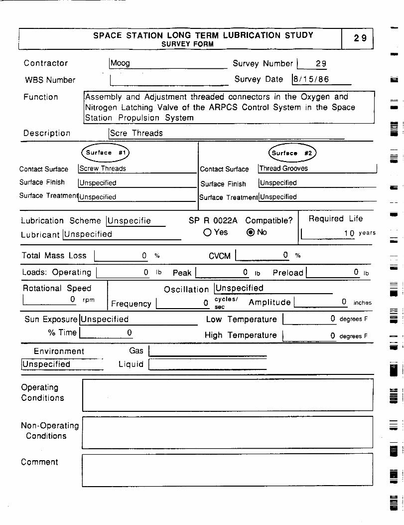
SPACE STATION LONG TERM LUBRICATION STUDYSURVEY FORM
29
IMoog Survey Number I 29
Survey Date 18/15/86
Contractor
WBS Number I
Function Assembly and Adjustment threaded connectors in the Oxygen and
Nitrogen Latching Valve of the ARPCS Control System in the Space
Station Propulsion System
Description IScre Threads
i
lii
b-
inIlll
m
II
Contact Surface IScrew Threads
Surface Finish IUnspecified
Surface Treatmen_Unspecified
Contact Surface IThread Grooves
Surface Finish IUnspecified
Surface TreatmenttUnspecified
m
Illl
Iiii
Lubrication Scheme IUnspecifie
Lubricant IUnspecified
SP R 0022A Compatible?
O Yes (_)No II Required
Life
1 0 years
mW
i
Total Mass Loss I 0 % CVCM I 0 %
Loads: Operating I 0 Ib Peak I 0 Ib Preload I 0 lb
m
i
Rotational Speed
I 0 rpm Frequency I
Oscillation IUnspecified
0 cycles/ AmplitudetSeC
0 inches
ZuIIII
Sun Exposure IUnspecified
% Time I 0n iii
Low Temperature I
High Temperature I
0 degrees F
0 degrees F
III '
Environment Gas I
IUnspecified Liquid [ ...........
OperatingConditions
Non-OperatingConditions
Comment
ill -
gm
uU
n
[]Hi
[]II
i
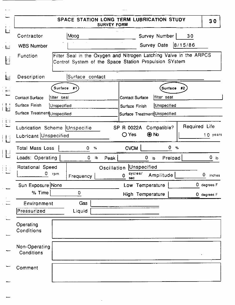
SPACE STATION LONG TERM LUBRICATION STUDYSURVEY FORM
3O
Contractor
= ,
L,_ WBS Number
IMoog
ISurvey Number I 30
Survey Date 18/1 5/86
Function Filter Seal in the Oxygen and Nitrogen Latching Valve in the ARPCS
Control System of the Space Station Propulsion SYstemt
_,_: Description ISurface contact
_-E_
Contact Surface Ifilter seal
!:_ Surface Finish IUnspecified
Surface Treatmen_ Unspecified
Contact Surface Ifilter seat
Surface Finish IUnspecified
Surface TreatmentlUnspecified
Lubrication Scheme IUnspecifie
Lubricant IUnspecified
SP R 0022A Compatible?
O Yes (_)No
Required Life
I 1 0 years
Total Mass Loss I 0 % CVCM I 0 %
LLoads: Operating I 0 Ib Peak I 0 Ib Preload I 0 ib
Z i Rotational Speed= .
"- [ 0 rpmFrequency I
Oscillation IUnspecified
0 cycles/ Amplitude lsec
0 inches
Sun Exposure INone
% Time I 0
Low Temperature I
High Temperature I
0 degrees F
0 degrees F
Environment Gas I
[Pressurized Liquid I
OperatingConditions
Non-OperatingConditions
Comment
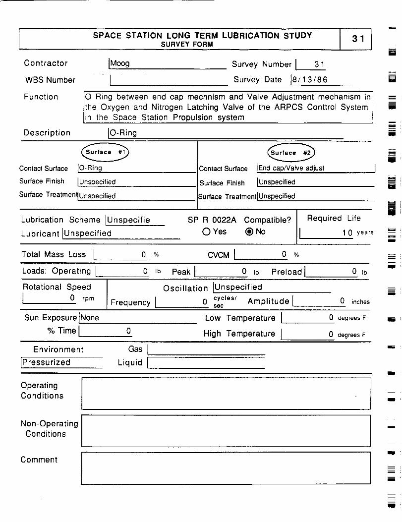
SPACE STATION LONG TERM LUBRICATION STUDYSURVEY FORM
31
B
Contractor
WBS Number
Function
Description
JMoog Survey Number I 3 1
I Survey Date 18/13/86
O Ring between end cap mechnism and Valve Adjustment mechanism in
the Oxygen and Nitrogen Latching Valve of the ARPCS Conttrol Systemin the Space Station Propulsion system
IO-Ring
i
I
m
Contact Surface
Surface Finish
IO-Ring
IUnspecified
Contact Surface
Surface Finish
[End cap/Valve adjust J
lUnspecified
Surface Treatment_Unspecified Surface TreatmentlUnspecified
Lubrication Scheme IUnspecifie
Lubricant IUnspecified
SP R 0022A Compatible? Required Life
OYes (_)No I 10 years
i
i
i
I
Total Mass Loss [ 0 % CVCMI o %Ill
Loads: Operating I 0 _b Peak I 0 _b Preload I 0 _b
Rotational Speed
I 0 rpmFrequency I
Oscillation IUnspecified
0 cycles/ Amplitude lse¢0 inches
m
Sun Exposure INone% Time I 0
Low Temperature I
High Temperature I
0 degrees F
0 degrees F
Environment
IPressurized
GasILiquid I
b
OperatingConditions
m
Non-OperatingConditions
Comment
m
i T
W
m

SPACE STATION LONG TERM LUBRICATION STUDYSURVEY FORM
L Contractor
" WBS Number
[Moog
1Survey Number I 32
Survey Date 18/12/86
Function Seal the Oxygen & Nitrogen Latching Valve casing from the electric
drive motor in the ARPCS COntro System of the Space Station
Propulsion System
; _ Description IBellevile Spring Seal
L Contact Surface
.... Surface Finish
_ Surface Treatmendunsnecified/ _"
IBville Spring Inner
iUnspecified
Contact Surface iBville Spring Outer
Surface Finish iUnspec ified
Surface TreatmentlUnspecified
Lubrication Scheme IUnspecifie
Lubricant iUnspecified
SP R 0022A Compatible?
O Yes (_)No
Required Life
I 0 years
Total Mass Loss I 0 % CVCM I 0 %
• : : Loads: Operating I 0 Ib Peak I 0 Ib Preload I 0 Ib
i _ i Rotational Speed!_ ! 0 rpm
Frequency [
Oscillation IUnspecified
0 cycles/ Amplitude lSeC
0 inches
Sun Exposure IUnspecified
% Time I 0
Low Temperature I
High Temperature I
0 degrees F
0 degrees F
Environment
IUnspecified
Gas 1
Liquid I
OperatingConditions
Non-Operating.- Conditions
_,-: Comment
=

SPACE STATION LONG TERM LUBRICATION STUDYSURVEY FORM
I
Contractor
WBS Number -
Function
Description
IMoog Survey Number I 33
- [ Survey Date 100/00/00
O Ring to seal the Relief Valve to the motor case in the ARPCS Control
System Oxygen and Niotrogen Latching Valve of Space Station
Propulsion System
IO-Rlng
iil
i
Ill
l
Contact Surface IO-Rlng
Surface Finish IUnspecified
Surface TreatmenlUnspecified
Contact Surface IRelief Valve
Surface Finish Unspecified
_urface Treatment IUnspecified
I
I
Lubrication Scheme IUnspecifie
Lubricant IUnspecified
SP R 0022A Compatible?
O Yes _) No
Required Life
1 0 years
b
lU
Total Mass Loss I 0 % CVCMI 0 %
Loads: Operating I 0 Ib Peak I 0 Ib Preload I 0 Ib II
Rotational Speed
I 0 rpmFrequency l
Oscillation IUnspecified
0 cycles/ Amplitude isec
0 inches
Z=[]
Sun Exposure INone
% Time I 0
Low Temperature I
High Temperature I
0 degrees F
0 degrees F
I
Environment
IPressurized
Gas I
Liquid I
!
m
OperatingConditions
m
Non-Operating
Conditionsn
CommentIlJ
mIII
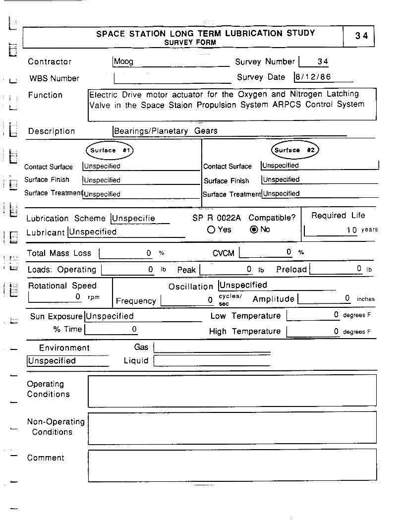
L
KSPACE STATION LONG TERM LUBRICATION STUDY
SURVEY FORM
Contractor
WBS Number
IMoog
ISurvey Number ! 34
Survey Date 18/1 2/86
"= .
L
Function Electric Drive motor actuator for the Oxygen and Nitrogen Latching
Valve in the Space Staion Propulsion System ARPCS Control SystemE
Description
iii
IBearings/Planetary Gears
Contact Surface IUnspecified
i _ Surface Finish [Unspecified
Surface Treatment[Unspecifiedi -.- i
!LLubrication Scheme IUnspecifie
i F
I I_
Contact Surface IUnspecified
Surface Finish IUnspec ified
Surface Treatment IUnspecified
SP R 0022A Compatible? Required Life
Lubricant IUnspecifiedO Yes (_) No 1 0 years
Total Mass Loss I 0 %t
CVCM I 0 %
Loads: Operating I 0 Ib Peak I 0 Ib Preload I 0 Ib
,i i_:_,, Rotational Speed
! _ 1 0 rpmFrequency I
Oscillation IUnspecified
0 cycles/ Amplitudelsoc
0 inches
Sun Exposure IUnspecified
% Time I 0
Low Temperature I
High Temperature I
0 degrees F
0 degrees F
Environment
lUnspecified
Gas I
Liquid I
OperatingConditions
Non-OperatingConditions I
-- Comment

SPACE STATION LONG TERM LUBRICATION STUDYSURVEY FORM
Contractor
WBS Number
[Lockheed Survey Number I 3 5
Survey Date 13/1/86 "
Function Wire Wrap transfers power and data across Beta Joint
Description IRelative Motion & Cc
lWire WrapContact Surface
Surface Finish JUnspecified
Surface Treatment_Unspecified
)ntact w/ Structure
3ontact Surface IAxle Housing
Surface Finish IUnspecified
Surface TreatmentlUnspecified
Lubrication Scheme INone Plann
Lubricant I
SP R 0022A Compatible? Required Life
OYes @_ I 10 years
i
mm
w
mI
i
[]
[]
Total Mass Loss IIHI
Loads: Operating I
0i i i
0
% CVCM I 0 O/o=
Ib Peak i 0 Ib Preload I 0 Ib
Rotational Speed
J0.00000405 rpm Frequency I
Oscillation IContinuous
0 cycles/ Amplitude lsec
0 inches
z
I
Sun Exposurellntermittent
% Time I 6 4
Low Temperature [
High Temperature I
0 degrees F
0 degrees F
Environment
Ivacuum
Gas i
Liquid J
mi
OperatingConditions
I
Non-OperatingConditions
Comment
R
M
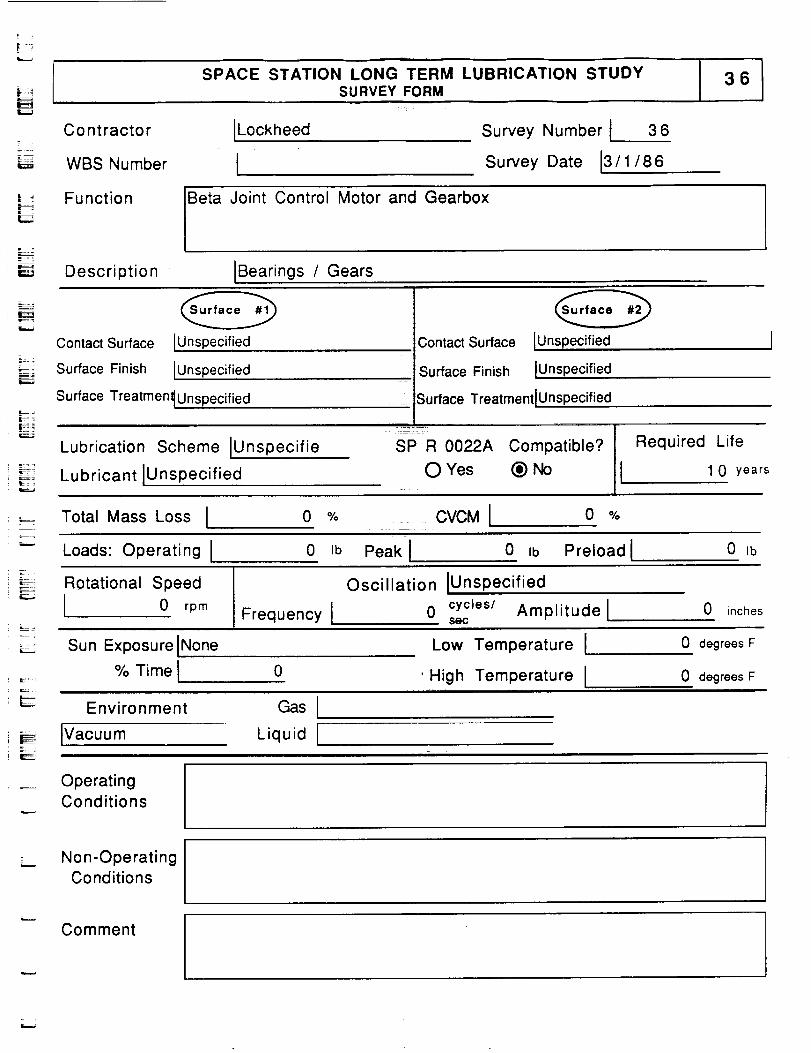
SPACE STATION LONG TERM LUBRICATION STUDYSURVEY FORM
L_
R
ILockheed Survey Number 3 6
Date 13/1/86Survey
Contractor
WBS Number I
Function Beta Joint Control Motor and Gearbox
IBearings / GearsDescriptionI
¢....,
Contact Surface
Surface Finish
[Unspecified
[Unspecified
Surface Treatmen_ Unspecified
Contact Surface
Surface Finish
IUnspecified
IUnspecified
Surface TreatrnentlUnspecified
Lubrication Scheme iUnspecifie
i _;;F_ Lubricant IUnspecified
SP R 0022A Compatible?
O Yes (_) No
Required Life
1 0 years
Total Mass Loss I 0 % CVCMI 0 %
Loads: Operating I 0 Ib Peak I 0 Ib Preload I 0 Ib
:-_ Rotational Speed
I 0 rpmFrequency I
Oscillation IUnspec ified
0 cycles/ Amplitude lsec
0 inches
L
Sun Exposure INone% Time i 0
Low Temperature I
'High Temperature I
0 degrees F
0 degrees F
Environment Gas [
Ivacuum Liquid [
OperatingConditions
Non-OperatingConditions
,r....*
Comment

SPACE STATION LONG TERM LUBRICATION STUDYSURVEY FORM
m
Contractor
WBS Number
Function
Description
[Lockheed
ISurvey Number [ 3 7
Survey Date J3/1/86
Main Bearings in the housing
System
of the Beta Joint of the Electrical Power
IMain Bearings
u
m
m
I
Contact Surface
Surface Finish
Ilnner Race
[Unspecified
Contact Surface
Surface Finish
[Outer Race
[Unspecified
Surface Treatmen_ Unspecified
Lubrication Scheme [Unspecifie
Lubricant IUnspecified
;urface TreatmentlUnspecified
I
SP R 0022A Compatible? III Required LifeO Yes (_) No 1 0 years
a
I
I
m=i
Total Mass Loss I 0 % CVCM I 0 %m
Loads: Operating I 0 Ib Peak I 0 =b Preload I 0 _b
Rotational Speed
I 0 rpm Frequency I
Oscillation IUnspec ified
0 cycles/ Amplitude lsec
0 inches
Sun Exposurellntermittent
% Time I 6 4
Environment Gas 1
_/acuum Liquid[
Low Temperature I
High Temperature Iii 1|
0 degrees F
0 degrees F
W
! !
!
Operating
Conditions i !
Non-Operating
Conditions|
z :
Comment
m
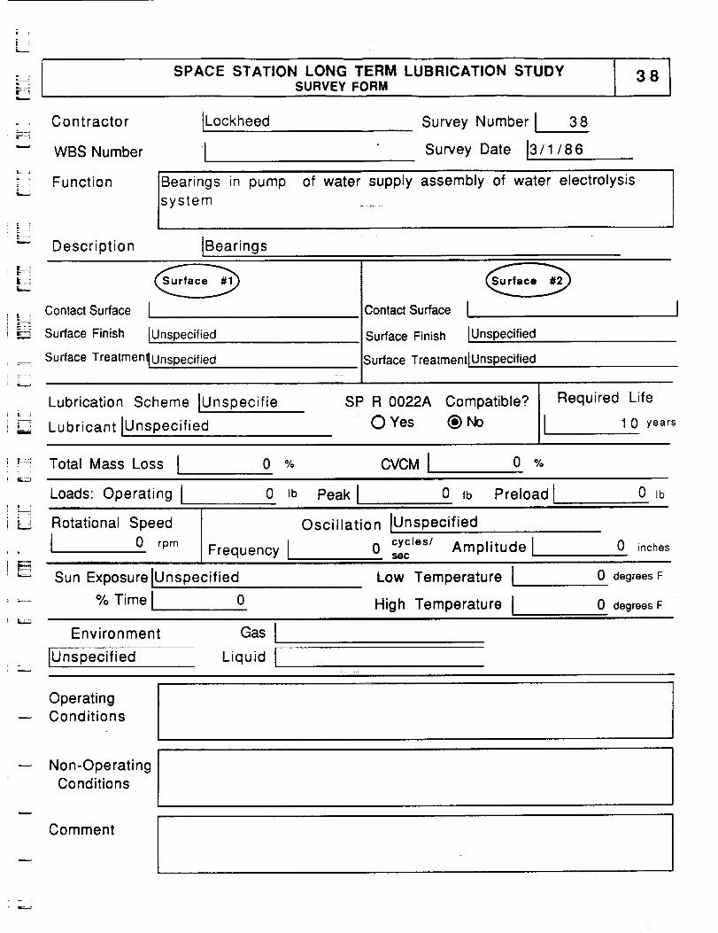
bSPACE STATION LONG TERM LUBRICATION STUDY
SURVEY FORM38
Contractor
WBS Number
ILockheed
1Survey Number I 38
Survey Date 13/1/86
Function Bearings in
system
pump of water supply assembly of water electrolysis
i--=,._
Description IBearingsLJ
] _:=,
Contact Surface I
Surface Finish IUnspecified
Surface Treatmenl_Unspecified
Lubrication Scheme IUnspecifie
Lubricant iUnspecified
ContactSurface I
Surface Finish IUnspecified
Surface TreatmentlUnspecified
SP R 0022A Compatible? Required Life
OYes (_)No I 10 years
-_-: Total Mass Loss I 0 % CVCM I 0 %
i _
Loads: Operating l
Rotational Speed
I 0 rpm
0 Ib
Frequency I
Peak I 0 tb Preload I 0 Ibi ii i
Oscillation IUnspec ified
0 cycies/ Amplitude l 0 inchessOC
Sun Exposure
% Time
Unspecified Low Temperature I
High Temperature I
0 degrees F
0 degrees F
Environment
Unspecified
Gas I
Liquid I
OperatingConditions
Non-OperatingConditions
Comment
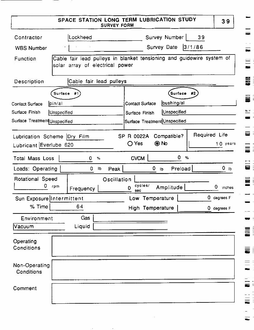
SPACE STATION LONG TERM LUBRICATION STUDYSURVEY FORM
39
Contractor
WBS Number
Function
Description
ILockheed
I
Survey Number I 39
Survey Date 03/1/86
Cable fair lead pulleys in blanket tensioning and guidewire system of
solar array of electrical power
ICable fair lead pulleys
U
i
i
_-- [
Contact Surface IPin/at
Surface Finish IUnspecified
Surface Treatment IUnspecified
Contact Surface Ibushing/al
Surface Finish IUnspecified
Surface TreatmentlUnspecified
m_
-'==-i
i !
Lubrication Scheme Dry Film
Lubricant IEverlube 620
SP R 0022A Compatible?
O Yes (_) No
Required Life
I 1 0 years
U
Total Mass Loss I o O,o CVOMt 0 O,o
Loads: Operating I 0 ib Peak I 0 ,b Preload I 0 Ib
Rotational Speed
I 0 rpm
Oscillation I
Frequency I 0 secCyCles/ Amplitude l 0 inches
Sun Exposurellntermittent Low Temperature I 0 degrees F
% Time I 64 High Temperature I 0 degrees F
I •
Environment Gas I
Ivacuum Liquid I
OperatingConditions
Non-OperatingConditions
Comment
a
i
R
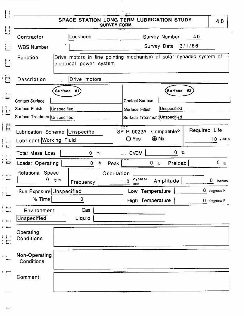
SPACE STATION LONG TERM LUBRICATION STUDYSURVEY FORM
4O
Co ntracto r ILockheed
WBS Number 1
Survey Number I 40
Survey Date [3/1/86
Function Drive motors in fine pointing mechanism of solar dynamic system of
electrical power systemi .,
L-:Description IDrive motors
r--__-
Contact Surface I
_!_ Surface Finish IUnspecified
"-- Surface Treatmen_Unspecified
Contact Surface I
Surface Finish IUnspec ified
Lubrication Scheme IUnspecifie
Lubricant IWorking Fluid
Surface Treatment IUnspecified
..... T--:" "
SP R 0022A Compatible?
O Yes _ No
Required Life
I 1 0 years
Total Mass Loss I 0 % CVCMI 0 %
Loads: Operating [ 0 Ib Peak[ ...... 0 ,b Preload I 0 Ib
Rotational Speed
I 0 rpm Frequency I
Oscillation I
0 cycles/ Amplitude lsec
0 inches
L
i --z;i;
Sun Exposure
% Time
Unspecified
0
Environment Gas l - r
IUnspecified Liquid I
Low Temperature I
High Temperature I
0 degrees F
0 degrees F
f
E
¢:_
OperatingConditions
Non-OperatingConditions
Comment
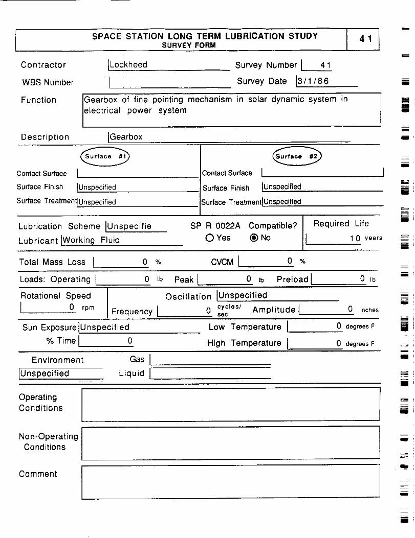
SPACE STATION LONG TERM LUBRICATION STUDYSURVEY FORM
Contractor
WBS Number
Function
Description
JLockheed Survey Number J 41
Survey Date J3/1/86
Gearbox of fine pointing mechanism in solar dynamic system in
electrical power system
IGearbox
i
I
mm
mIll
II
Contact Surface J
Surface Finish JUnspecified
Surface TreatmenlUnspecified
Contact Surface I
Surface Finish
Surface Treatment IUnspecified
lunspecified ,,
Lubrication Scheme IUnspecifie
Lubricant IWorking Fluid 1
SP R 0022A Compatible?
O Yes _) No
Required Life
1 0 years
m
I
m_=i
li
i
iu
Total Mass Loss I o % CVCMI o %m
Loads: Operating I 0 tb Peak I 0 Ib Preload i 0 Jb
Rotational Speed
I 0 rpm Frequency I
Sun ExPosure iUnspecified
% Time I 0
Oscillation jUnspecified
0 cycles/ Amplitude Jsec
i
Low Temperature I
High Temperature !
0 inches
0 degrees F
0 degrees F
Environment Gas I
iE_
m
Ill
IUnspecified Liquid I ===.
Ill
OperatingConditions !
Ill
Non-OperatingConditions
Comment
I
i
I
m
i
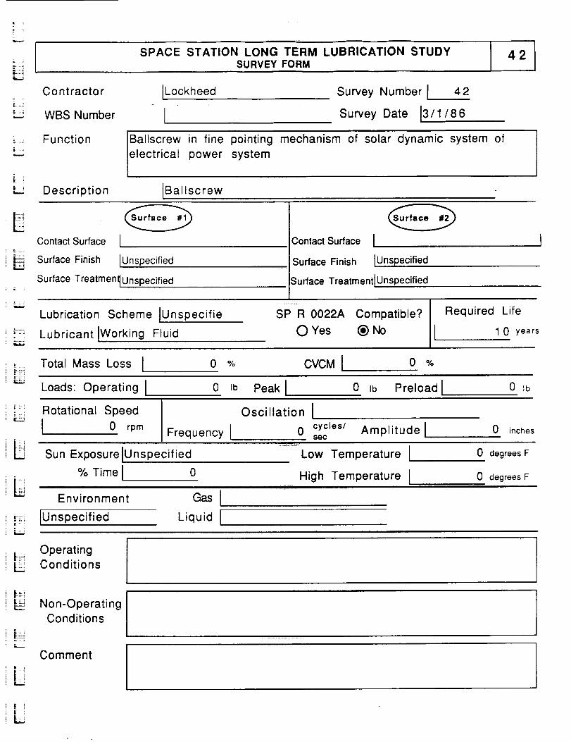
i SPACE STATION LONG TERM LUBRICATION STUDYSURVEY FORM
42
- z
Contractor
WBS Number
ILockheed
ISurvey Number I 42
Survey Date 13/1/86
= Function Ballscrew in fine pointing mechanism of solar dynamic system of
electrical power system
Description IBallscrew
LE
Contact Surface I
Surface Finish IUnspecified
Surface Treatmen_ Unspecified
Contact Surface I
Surface Finish IUnsp,,e,cified
Surface TreatmentIUnspecified
Lubrication Scheme IUnspecifie
Lubricant IWorking Fluid
SP R 0022A Compatible?
O Yes (_) No
Required Life
I 1 0 years
Total Mass Loss I 0 % CVCM! o %
Loads: Operating I 0 Ib Peak I 0 Ib Preload I 0 Ib
t:_:! Rotational Speed
I 0 rpmFrequency [
Oscillation I
0 cycles/ Amplitude lsec
0 inches
Sun Exposure IU nspecified Low Temperature I 0 degrees F
% Time I 0 High Temperature I
Environment Gas I
0 degrees F
_:; IUnspecified Liquid I
|: OperatingL Conditions
|_.-
,___;JNon-OperatingConditions
Comment
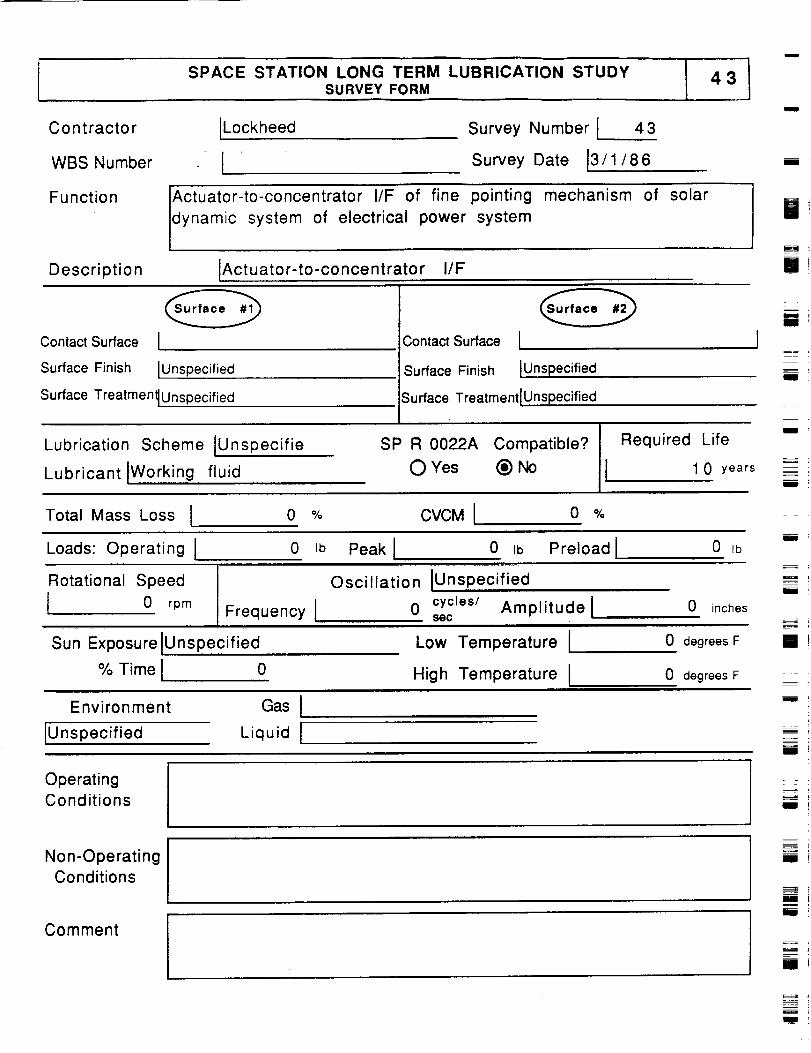
SPACE STATION LONG TERM LUBRICATION STUDYSURVEY FORM
43
Contractor
WBS Number
[Lockheed
ISurvey Number [ 43
Survey Date 13/1/86
m
limb
Function
Description
Actuator-to-concentrator I/F of fine pointing
dynamic system of electrical power system
mechanism of solar
[Actuator-to-concentrator , I/F
ii
Contact Surface [
Surface Finish IUnspecified
Surface Treatmen_ Unspecified
Contact Surface [
Surface Finish [Unspecified
Surface Treatment]Unspecified
aIII
Illl
Lubrication Scheme ]Unspecifie
Lubricant[Working fluid
SP R 0022A Compatible?
0 Yes _) No
Required Life
1 0 years
iiii
I
Total Mass Loss ] 0 % CVCMI 0 %
Loads: Operating [ 0 Ib Peak I 0 ab Preload I 0 IbIll
Rotational Speed
0 rpm Frequency I
Sun Exposure lUnspecified
% Time i 0
Oscillation IUnspec ified
0 cycles/ Amplitude lsec
"iLow Temperature
High Temperature I
0 inches
0 degrees F
0 degrees F
mi
m
i
Environment
IUnspecified
Gas I
Liquid [
mw
OperatingConditions
Non-OperatingConditions
Comment
IIi
!i
f
i!
Ill
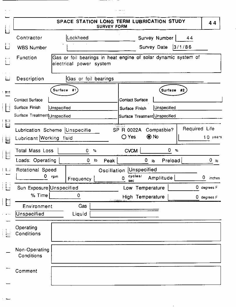
SPACE STATION LONG TERM LUBRICATION STUDYSURVEY FORM
Co ntractor [Lockheed
L WBS Number I
Survey Number I 44
Survey Date 13/1/ 86
Function IGas or foil bearings in heat engine of solar dynamic system of
electrical power system
Description IGas or foil bearings
= ,
Contact Surface
_ Surface Finish
IIUnspecified
Contact Surface I ]
Surface Finish IUnspecified
Surface Treatmen_ Unspecified
Lubrication Scheme [Unspecifie
i L_ [Working fluid_ _-. Lubricant
Surface Treatment I Unspecified
SP R 0022A Compatible?
O Yes (_) No
Required Life
I 1 0 years
_ Total Mass Loss I o %
Loads: Operating I 0 ib
CVCM I 0 %
Peak I 0 Ib Preload I 0 Ib
Rotational Speed
I 0 rpmFrequency I
Oscillation IUnspecified
0 cycles/ Amplitude lsec
0 inches
L
Sun Exposure IUnspecified
% Time I 0
Environment
IUnspecified
Gas I
Liquid I
Low Temperature !
.......... High Temperature [.... 1 _ ilUlllllll i iii i
0 degrees F
0 degrees F
, Operating: _ Conditions
Non-OperatingConditions
Comment
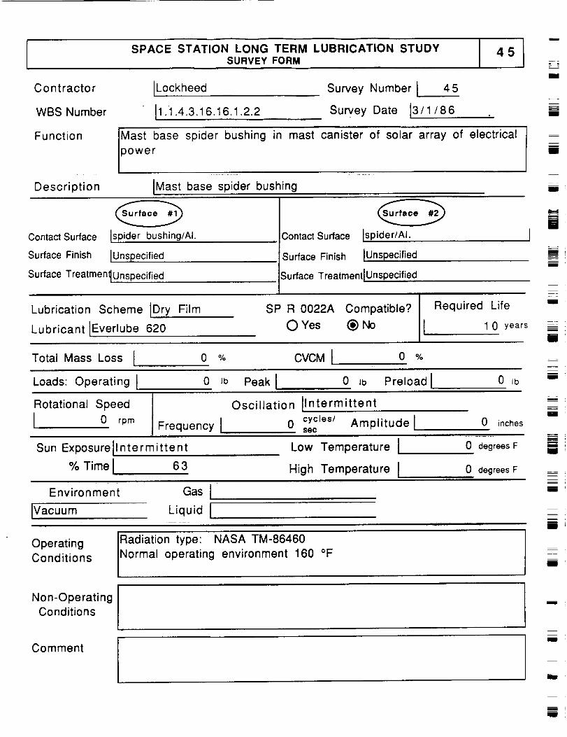
SPACE STATION LONG TERM LUBRICATION STUDYSURVEY FORM
m
Contractor
WBS Number
[Lockheed
[1 .i .4.3.16.16.1.2.2
Survey Number i 4 5
SurveY Date 13/1/86
i
I
Function
Description
Mast base spider bushing
power
in mast canister of solar array of electrical
IMast base spider bushing
m
m
D
Contact Surface [spider bushing/AI.
Surface Finish IUnspecified
Surface Treatmen_ Unspecified
Contact Surface
Surface Finish
Surface TreatmentlUnspecified
O WIspider/Al. t
IUnspecified _.==----=
m
Lubrication Scheme [Dry Film
Lubricant IEverlube 620
SP R 0022A Compatible?
0 Yes _) No
m
Required Life "=
J 1 0 years =
Total Mass Loss I 0 % CVCMI 0 % h_m
Loads: Operating t 0 lb Peak J 0 Ib Preload I 0 IbmI
Rotational Speed
I 0 rpm Frequency I!1 L @ira .
Sun Exposurell ntermittent
% Time I 6 3
Oscillation Ilntermittent
0 cyctes/ Amplitude lsec
0 inches
Low Temperature ! 0 degrees F
High Temperature I 0 degreesF
Environment Gas I
m
I
R
I
Ivacuum Liquid J
OperatingConditions
Radiation type NASA TM-86460
Normal operating environment 160 °F
m
m
I
m
Non-OperatingConditions
Comment
mm
I
=!
mi
U
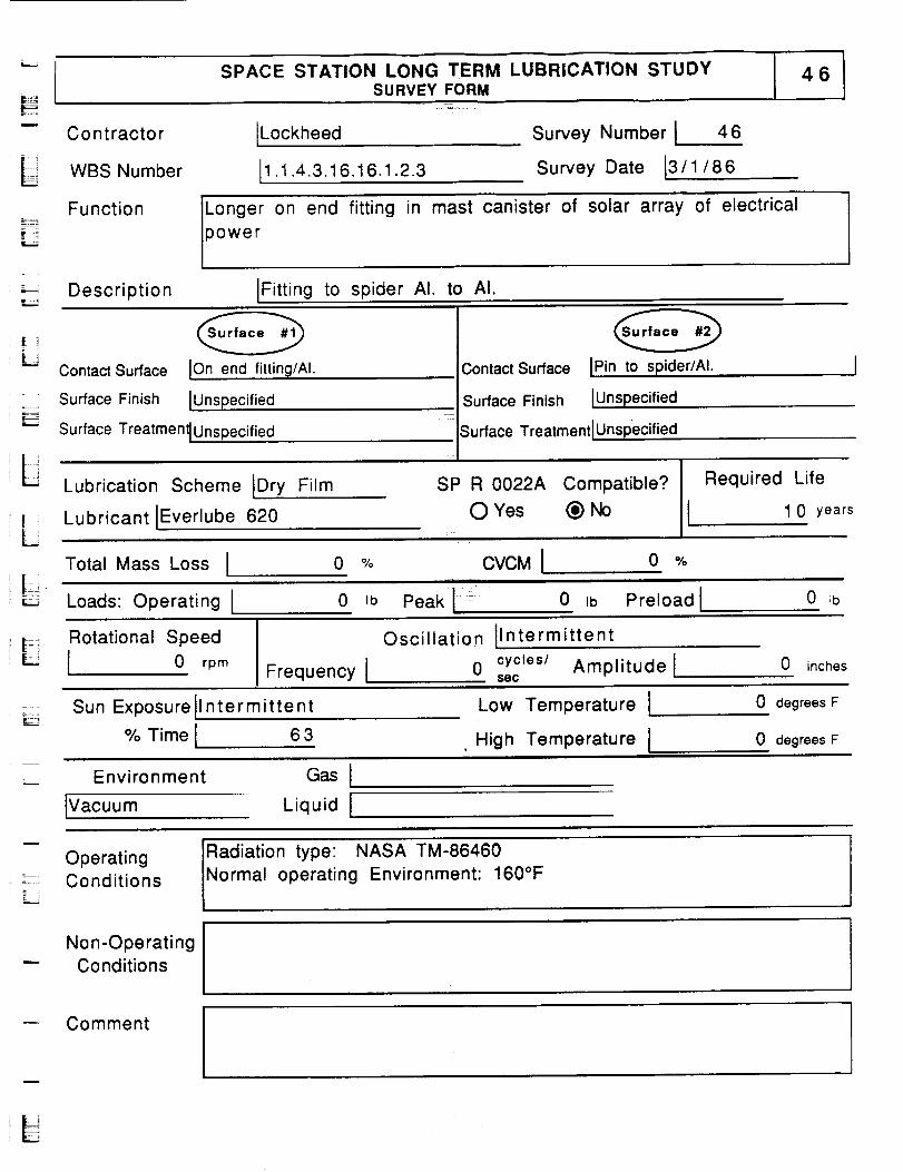
SPACE STATION LONG TERM LUBRICATION STUDYSURVEY FORM
L
Contractor
WBS Number
Function
ILockheed
11.1.4.3.16.16.1.2.3
Survey Number I 46
Survey Date 13/1/86
Longer on end fitting in mast canister of solar array of electrical
3ower
Description ]Fitting to spider AI. to AI.
IL
i.....
L
L
ContactSurface Ionend fitting/AI.
Surface Finish IUnspecified
Surface Treatmen_Unspecified
Lubrication Scheme IDry Film
Lubricant IEverlube 620
Contact Surface IPin to spider/AI.
Surface Finish lUnspecified
Surface Treatment IUnspecified
SP R 0022A Compatible?
O Yes _No
Required Life
1 0 years
Total Mass Loss I 0 °Jo CVCMI o Ojo
Loads: Operating I 0 =b Peak !_ 0 Ib Preload I 0 _b
_! Rotational Speed
I 0 rpm
Oscillation IIntermittent
Frequency I 0 secCyctes/Amplitude l 0 inches
E_Sun Exposurellntermittent
% Time I 6 3
Low Temperature I
High Temperature I
0 degrees F
0 degrees F
Environment
iVacuum
Gas I
Liquid I
Operating: _ Conditions
Radiation type: NASA TM-86460
Normal operating Environment: 160°F
Non-OperatingConditions
-- Comment
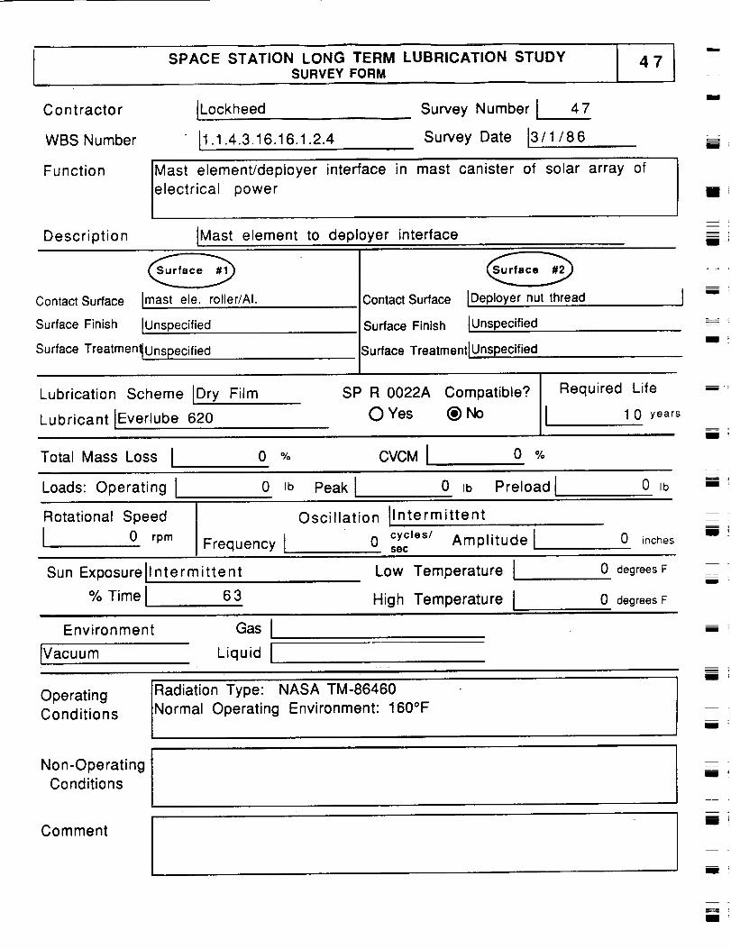
SPACE STATION LONG TERM LUBRICATION STUDYSURVEY FORM
Contractor
WBS Number
Function
Description
ILockheed
I1.1.4.3.16.16.1.2.4
Survey Number I 47
Survey Date J3/1/86
Mast element/deployer interface in mast canister of solar array of
electrical power
tMast element to deployer interface
_Im
i
ii
iJ
Contact Surface Imast ele. roller/AI.
Surface Finish IUnspecified
Surface Treatmen_ Unspecified
ContactSurface JDeployernut thread
Surface Finish JUnspecified
Surface TreatmentlUnspecified
m
I __i
Lubrication Scheme Dry Film
Lubricant IEverlube 620
SP R 0022A Compatible?
O Yes (_) No
Required Life
1 0 years
Total Mass Loss J 0 °Jo CVCMI o Ojo
Loads:Operating I 0 ,b Peak I 0 ,b Preload I 0,b
n
R
Rotational Speed
I 0 rpm
Oscillation I Intermittent
Frequency t 0 cycleS/secAmplitude l 0 inchesi ;
Sun ExposureJl ntermittent
% Time J 6 3
Low Temperature t
High Temperature !
0 degrees F
0 degrees F
Environment
IVacuum
Gas I
Liquid ImmI
OperatingConditions
Non-OperatingConditions
Comment
Radiation Type: NASA TM-86460
Normal Operating Environment: 160°F
i
m
mIll
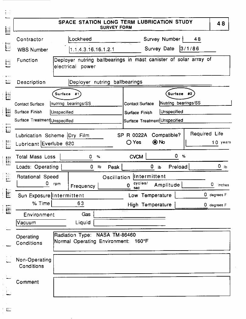
SPACE STATION LONG TERM LUBRICATION STUDYSURVEY FORM
Contractor
WBS Number
ILockheed.-
I1.1.4.3.16.16.1.2.1
Survey Number I 48
Survey Date 13/1/86
Function
_._ Description
Deployer nutring ballbearings in mast canister of solar array of
electrical power
IDeployer nutring ballbearings
Contact Surface
_ Surface Finish
Inutring bearings/SS
IUnspecified
Surface Treatmen_ Unspecified
Contact Surface INutring bearings/SS
Surface Finish IUnspecified
Surface TreatmentlUnspecified
Lubrication Scheme IDry Film
Lubricant IEverlube 620
SP R 0022A Compatible?
O Yes @ No
Required Life
1 0 years
......._.Total Mass Loss I 0 % CVCM I 0 %
Loads: Operating I 0 Ib Peak I 0 ab Preload I 0 Ib
Rotational Speed
-'_'_ I 0 rpm
EFrequency I
Oscillation IIntermittent
0 cycles/ Amplitude lsec
0 inches
Sun Exposurell ntermittent Low Temperature I 0 degrees F
% Time I
Environment
Ivacuum
63
Gas I
Liquid I
High Temperature I 0 degrees F
OperatingConditions
Radiation Type' NASA TM-86460
Normal Operating Environment: 160°F
_:_ Non-Operating
Conditions
Comment
.._, .
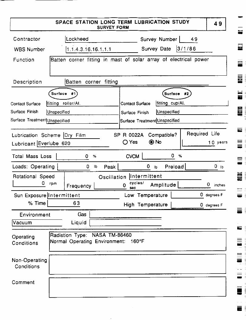
Contractor
WBS Number
Function
Description
SPACE STATION LONG TERM LUBRICATION STUDYSURVEY FORM
J
ILockheed
11.1.4.3.16.16.1.1.1
Survey Number I 49
Survey Date 13/1/86
Batten corner fitting in mast of solar array of electrical power
IBatten corner fitting
I
m
m
II
B
ill
Contact Surface
Surface Finish
Ifitting rotler/Al.
IUnspecified
Contact Surface
Surface Finish
Ifitting cup/AI. 1
IUnspecified
Surface Treatmen_ Unspecified Surface TreatmentlUnspecified
Lubrication Scheme IDry Film
Lubricant IEverlube 620
SP R 0022A Compatible? Required Life
OYes ®No I 10 years
m
II
=
m!
Total Mass Loss I 0 % CVCM I 0 %
Loads: Operating I 0 Ib Peak I 0 Ib Preloadl 0 ib
Rotational Speed
I 0 rpmFrequency I
Oscillation Ilntermitte nt
0 cycles/ Amplitude lsec
0 inches
mi
fill
Sun Exposurellntermitte nt
% Time I 6 3
Low Temperature I
High Temperature Ii i iii i
Environment Gas I
Ivacuum Liquid I
0 degrees F
0 degrees F
u !
li
i
OperatingConditions
Non-OperatingConditions
Radistion Type: NASA TM-86460
Normal Operating Environment: 160°Fmm !
Comment--- iillu_
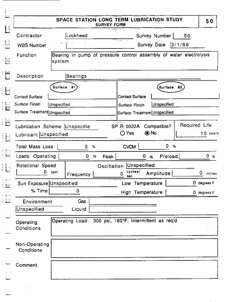
SPACE STATION LONG TERM LUBRICATION STUDYSURVEY FORM
5O
L_
Contractor
..... WBS Number
ILockheed Survey Number I 50
Survey Date 13/1/86
Function Bearing
system
in pump of pressure control assembly of water electrolysis
Description IBearings
i ,
L_
Contact Surface I
Surface Finish IUnspecified
Surface Treatmen_ Unspecified
Contact Surface I
Surface Finish IUnspecified
Surface Treatment IUnspecified
Lubrication Scheme [Unspecifie
Lubricant IUnspecified
SP=R 0022A Compatible?
O Yes @No
Required Life
1 0 years
Total Mass Loss I 0 % CVCM I 0 %
Loads: Operating l 0 Ib Peak I 0 i1_ Preload I 0 lb
;:J Rotational Speed
_-'-' I 0 rpmFrequency I
Oscillation IUnspecified
0 cycles/ Amplitude lsec
0 inches
Sun Exposure IU nspecified
% Time I 0
Low Temperature I
.....High Temperature I
0 degrees F
0 degrees F
Environment
Unspecified
Gas I
Liquid I
OperatingConditions
Operating
Load: 300 psi, 180°F, Intermittent as req'd
Non-OperatingConditions
Comment

SPACE STATION LONG TERM LUBRICATION STUDYSURVEY FORM
Contractor
WBS Number
Function
Description
ILockheed
ISurvey Number I 51
Survey Date 13/1/86
Motor pinion gear in cover blanket preload system of solar array of
electrical power
Moter pinion gear
lil
Ill
I
Contact Surface
Surface Finish
Iworn gear/Al.
IUnspecified
Contact Surface
Surface Finish
ILatchmember/SS
IUnspecified
Surface Treatmen_ Unspecified Surface Treatment I Unspecified
Lubrication Scheme JDry Film
Lubricant JEverlube 620
SP R 0022A Compatible?
O Yes (_) No
Required Life
1 0 years
Total Mass Loss I 0 % CVCMI 0 %
L
R
m
I
I11
Loads: Operating J 0 Ib Peak I 0 Ib Preload I 0 Ib III '
Rotational Speed
I 0 rpm Frequency I
Oscillation IUnsp ecified
0 cycles/ Amplitude lsec
0 inches
m
llll
Sun Exposurell ntermittent
% Time I 6 4
Low Temperature I
High Temperature I
0 degrees F
0 degrees F
mi
Environment
IVacuum
Gas i
Liquid I
i
_.m
Operating
Conditions=
Non-Operating
Conditions
Comment
I
ul
I
m
ii

i=_--
SPACE STATION LONG TERM LUBRICATION STUDYSURVEY FORM
Co ntracto r ILockheed
_= WBS Number, ISurvey Number I 52
Survey Date 13/1/ 8 6
L
Function Motor ballbearings in ocver blanket preload system of solar array of
electrical power
Description IMotor ballbearings
= :
Contact Surface IBearings/SS
;:_ Surface Finish IUnspecified
Contact Surface
Surface Finish
IRace/SSIUnspecified
Surface Treatmen_ Unspecified Surface TreatmentlUnspecified
Lubrication Scheme IFluid *
Lubricant IBraycote 601
SP R 0022A Compatible?
" O Yes (_)No
Required Life
I 1 0 years
_,,__ Total Mass Loss I 0 % CVCM I 0 %
Loads: Operating l
Rotational Speed
I 0 rpm
0 Jb Peak [ 0 ,b Preload I 0 Ib
Frequency t
Oscillation IUnspec ified
0 cycles/ Amplitude lsec
0 inches
Sun Exposurell ntermittent
% Time I 6 4
Low Temperature IHigh Temperature I
0 degrees F
0 degrees F
Environment
IVacuum
Gas I
Liquid I
OperatingConditions
_,,_ Non-OperatingConditions
Grease
r.._...,
Comment
lt
J
L-..
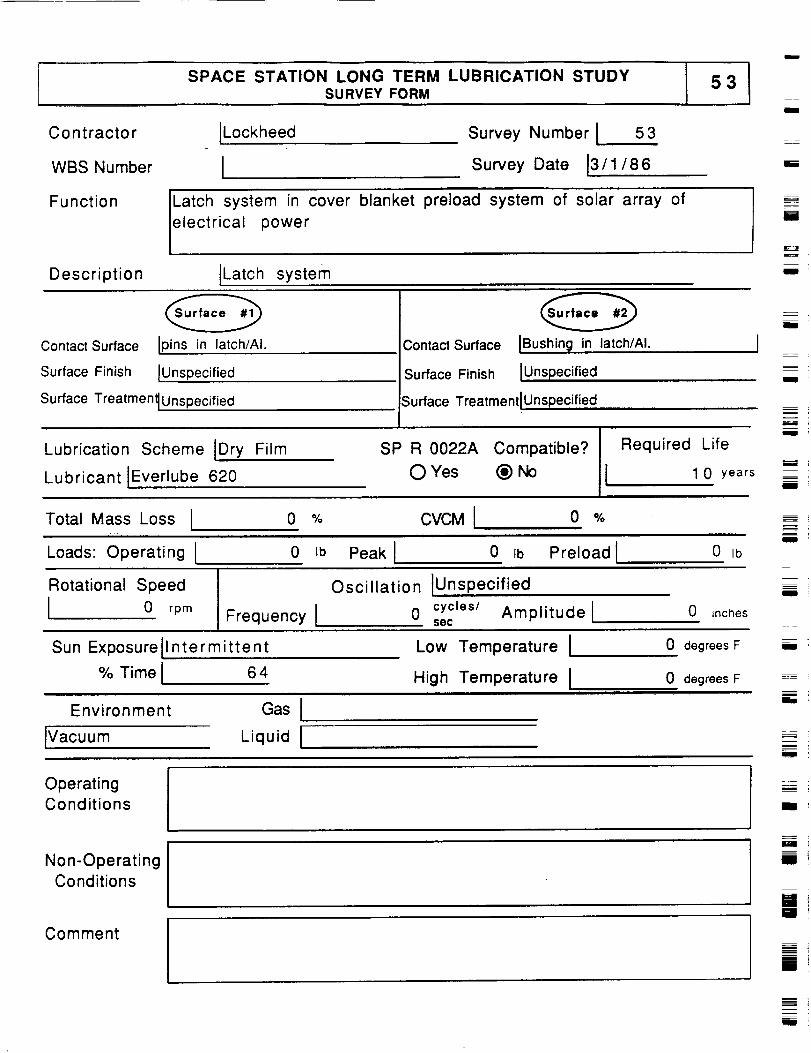
SPACE STATION LONG TERM LUBRICATION STUDYSURVEY FORM
53
Contractor
WBS Number
Function
Description
[Lockheed
ISurvey Number I 53
Survey Date 13/1/86
Latch system in cover blanket preload system of solar array of
electrical power
ILatch system
I
ii
ii
_==
i
Contact Surface IPins in latch/AI.
Surface Finish [Unspecified
Surface Treatmen_ Unspecified
Contact Surface iBushing in latch/AI.
Surface Finish IUnspec ified
Surface TreatmentlUnspecified
II
I '
.--.
Lubrication Scheme IDry Film
Lubricant IEverlube 620
SP R 0022A Compatible?
0 Yes (_)No
Required Life
I 1 0 years _ ii
Total Mass Loss I o % CVCMI o %
Loads: Operating I 0 ,b Peak I 0 ,b Preload I 0,b
Rotational Speed
I 0 rpm
Oscillation IUnspecified =--1
Frequency I 0 cycles/sec Amplitude l 0 inches
LOW Temperature I 0 degrees F
High Temperature I 0 degrees F
Sun Exposure
% Time
Intermittent
64
Environment
IVacuum
Gas I
Liquid I
li ,
mi
!
Operating
Conditions
:._=
I
Non-Operating
Conditions
Comment
N
ii
mJi
!
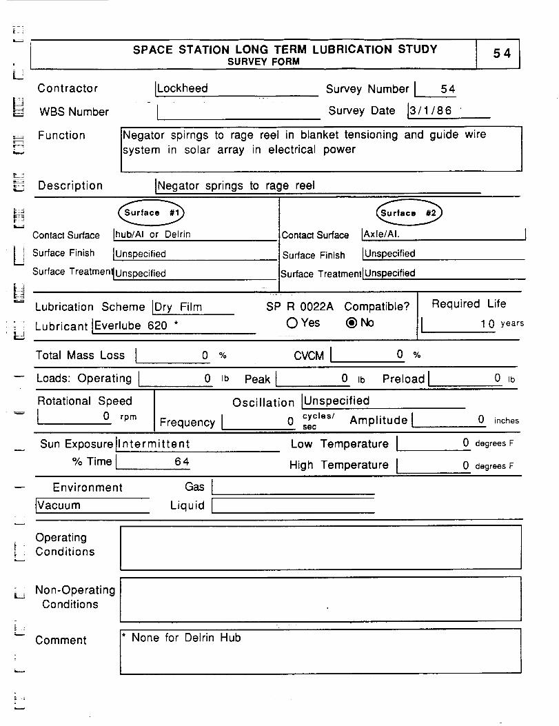
SPACE STATION LONG TERM LUBRICATION STUDYSURVEY FORM
LContractor
WBS Number
ILockheed
lSurvey Number I 54
Survey Date 13/1/86
F,Z_=.
r-----.,
Function Negator spirngs to rage reel in blanket tensioning and guide wire
system in solar array in electrical power
i_ __
Description INegator springs to rage reel
Contact Surface Ihub/AI or Delrin
Surface Finish IUnspecified
Surface Treatment IUnspecified
Contact Surface IAxle/AI.
Surface Finish lUnspec ified
Surface Treatment IUnspecified
H
Lubrication Scheme IDry Film
,......_, Lubricant IEverlube 620 *- =!
SP R 0022A Compatible? Required Life
O Yes (_) No 1 0 years
Total Mass Loss I 0 % CVCMI o %
Loads: Operating I 0 Ib Peak I 0 tb Preload I 0 Ib
Rotational Speed
l 0 rpm Frequency I
Oscillation IUnspecified
0 cycles/ Amplitudelsec
0 inches
Sun Exposurell ntermitte nt
% Time I 6 4
Low Temperature I
High Temperature I
0 degrees F
0 degrees F
-- Environment
Vacuum
Gas I
Liquid I
Operatingi Conditions
Non-OperatingConditions
* None for Delrin Hub
=
- :E
Comment
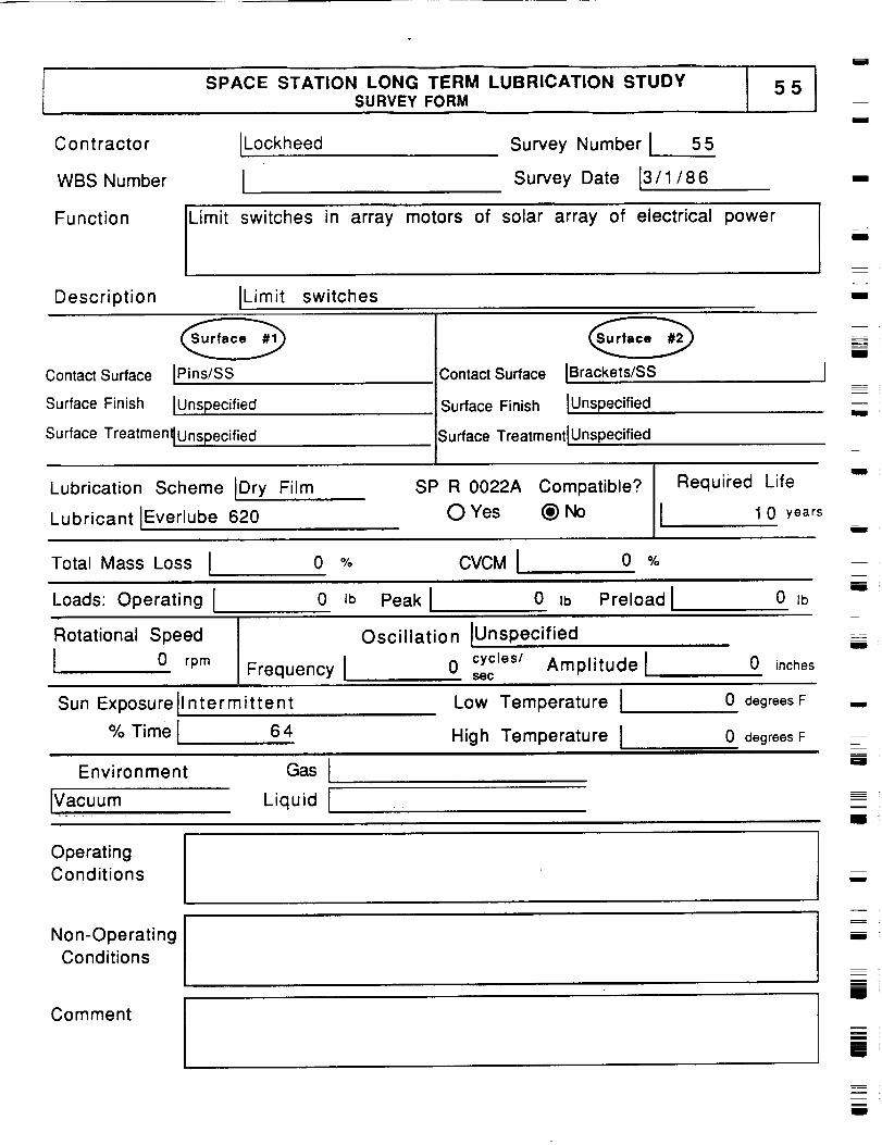
SPACE STATION LONG TERM LUBRICATION STUDY
i
SURVEY FORM
C o nt racto r ILockheed
WBS Number I
Survey Number I 55
Survey Date 13/1/86
i
I
Function Limit switches in array motors of solar array of electrical power
Description ILimit switches
i
I
Contact Surface IPins/SS
Surface Finish IUnspecified
Surface Treatmen_Unspecified
Contact Surface IBrackets/SS
Surface Finish IUnspec ified
Surface Treatment IUnspecified
m
I
i
Lubrication Scheme IDry Film
Lubricant IEverlube 620
SP R 0022A Compatible?
O Yes (_) No
Required Life
1 0 years
J
i
Total Mass Loss I 0 % CVCM I 0 %
Loads: Operating I 0 Ib Peak I 0 ,b Preload I 0 Ib
Ei
Rotational Speed
I 0 rpm Frequency I
Oscillation IUnspecified
0 cycles/ Amplitude lSOC
0 inches
i
Sun Exposurell ntermittent
% Time I 64
Low Temperature I
High Temperature I
Environment Gas I
IVacuum Liquid I
0 degrees F
0 degrees F
i
Ill '
I
OperatingConditions
w
Non-Operating
Conditions
i
m
i
Comment
[]
zJ
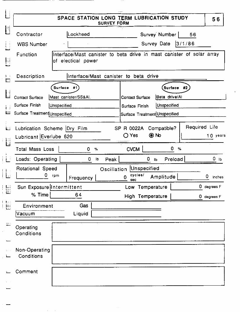
SPACE STATION LONG TERM LUBRICATION STUDYSURVEY FORM
= :
Contractor
WBS Number
ILockheed Survey Number I 56
Survey Date 13/ 1 / 8 6
LF_
Function lnterface/Mast canister to
of electical power
beta drive in mast canister of solar array
;___ Description Ilnterface/Mast canister to beta drive
OContact Surface IMast canister/SS&Al.
o _ Surface Finish IUnspecified
Surface Treatment_Unspecified
Contact Surface IBeta drive/AI
Surface Finish IUnspecified
Surface Treatment IUnspecified
Lubrication Scheme Dry Film
Lubricant IEverlube 620
SP R 0022A Compatible?
O Yes _) No
Total Mass Loss I 0 °Jo CVCMI|
! i:L Loads: Operating 0 Ib Peak
IIRequired Life
0 %
0 Ib Preload I
1 0 years
0 Ib
_ Rotational Speed
iL_ 1 0 rpm
Oscillation IUnspec ified
Frequency I 0 secCyCleS/Amplitude l 0 inches
w
Sun Exposurell ntermittent
% Time I 6 4
Low Temperature I
High Temperature I
0 degrees F
0 degrees F
',_-: Environment
IVacuum Liquid I
OperatingConditions
Non-Operating'_ Conditions
..- Comment
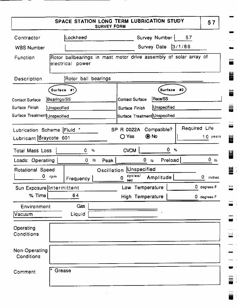
SPACE STATION LONG TERM LUBRICATION STUDYSURVEY FORM
57
C o n t racto r ILockheed
WBS Number I
Function
Survey Number I 57
Survey Date !3/1/86
Rotor ballbearings in mast motor drive assembly of solar array of
electrical power
Description IRotor ball bearings
I
i
[]
Contact Surface IBearings/SS
Surface Finish IUnspecified
Surface TreatmenlUnspecified
ContactSurface IRace/SS
Surface Finish IUnspecified
Surface TreatmentlUnspecified
m
I
=
!
I
Lubrication Scheme IFluid *
Lubricant II_raycote 601
SP R 0022A Compatible?
0 Yes (_)No
Required Life
I 1 0 years
i
iTotal Mass Loss I 0 % CVCM I 0 %
Loads: Operating I 0 ib Peak I 0 ib Preload I 0 Ib
Rotational Speed
0 rprn Frequency I
Oscillation IUnsp ecified
0 cycles/ Amplitude lSSC
0 inches
E!
Sun Exposurellntermittent
% Time I 64
Low Temperature I
High Temperature I
Environment Gas I
0 degrees F
0 degrees F
_B
lVacuum Liquid I mm
zmI
OperatingConditions
mw
mI
Non-OperatingConditions
Comment
* Greasem
F_Ill
m
[]
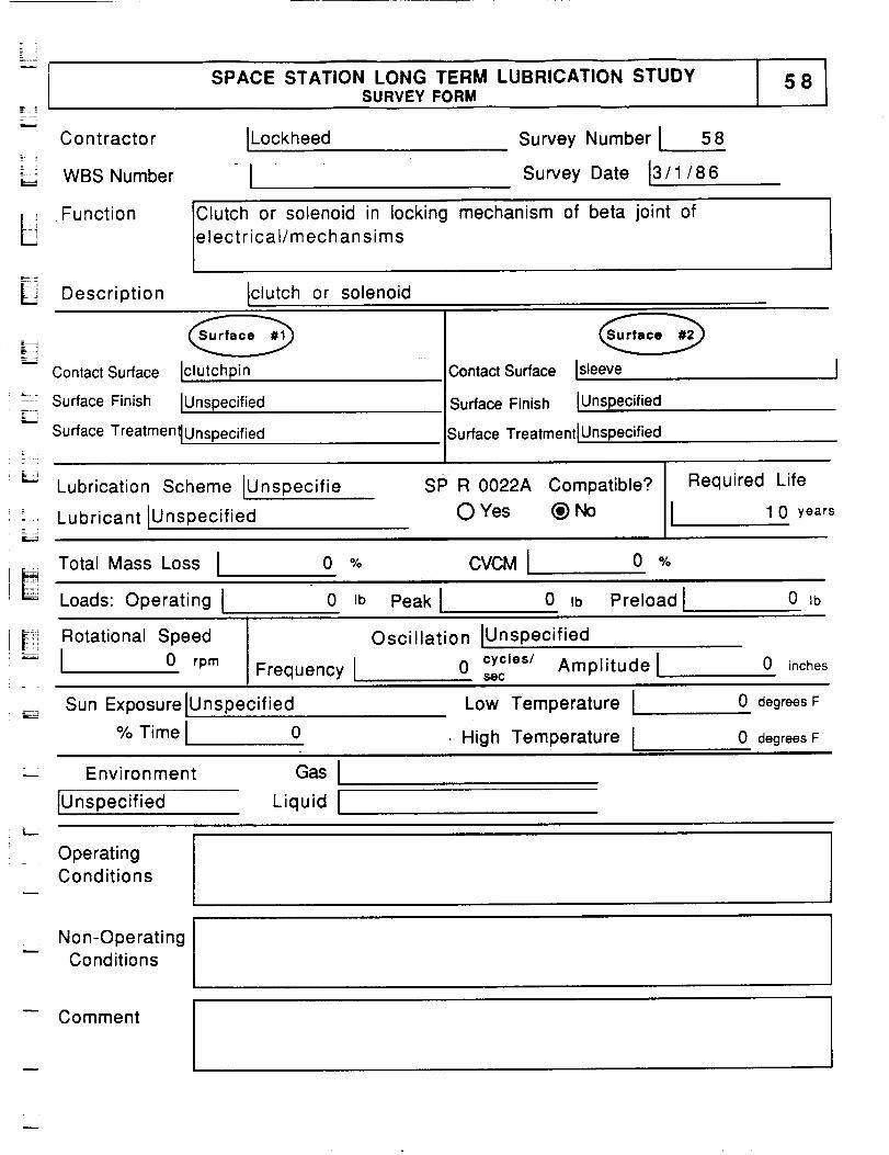
-C-2
SPACE STATION LONG TERM LUBRICATION STUDYSURVEY FORM
C o nt racto r ILockheed-: !
L_:_ WBSNumber - I
Survey Number I 58
Survey Date [3/1/86
_ FunctionE i " Clutch or solenoid in locking mechanism of beta joint of
electrical/mechansims
|_! Description Iclutch or solenoid
Contact Surface Iclutchpin
Surface Finish IUnspecified
Contact Surface
Surface Finish
Isleeve
IUnspecified
Surface Treatmenl IUnspecified ;urface Treatment IUnspecified
Lubrication Scheme IUnspecifie
Lubricant IUnspecified
SP R 0022A Compatible?
0 Yes @ No
Required Life
1 0 years
L Total Mass Loss I o % CVCMI o %
Loads: Operating I 0 Ib Peak I 0 ,b Preload I 0 Ib
El Rotational Speed
I 0 rpmFrequency I
Oscillation IUnspe cified
0 cycles/ Amplitude l$ec
0 inches
Sun ExposurelUnspecified
% Time I 0
Low Temperature !
High Temperature I
0 degrees F
0 degrees F
Environment
IUnspecified
GasILiquid I
OperatingConditions
Non-OperatingConditions
Comment I
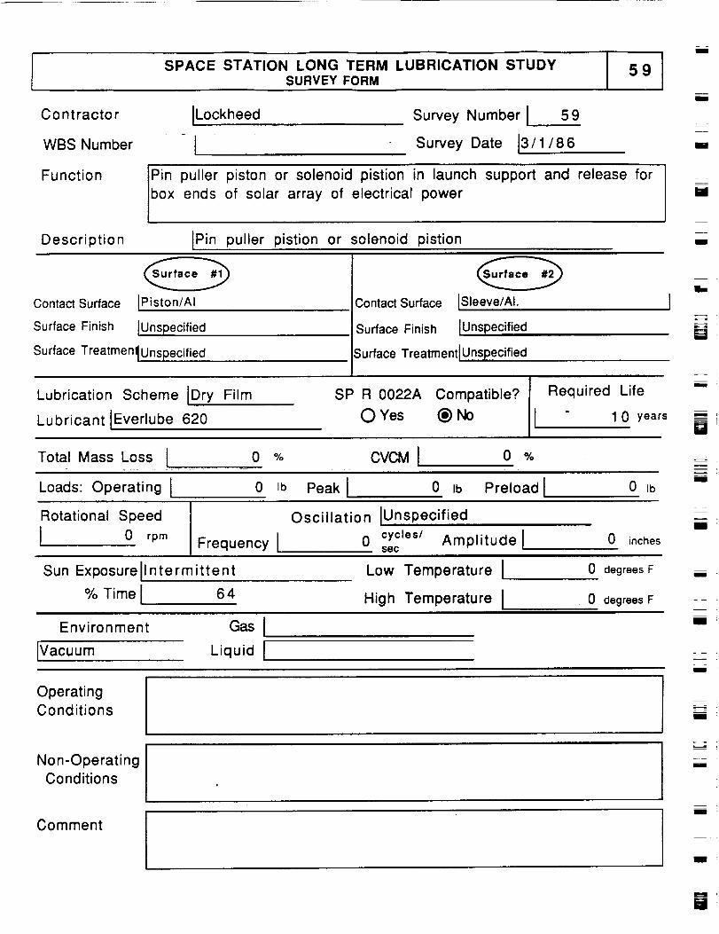
SPACE STATION LONG TERM LUBRICATION STUDYSURVEY FORM
I
Contractor
WBS Number
Function
Description
ILockheed Survey Number I 59
[ Survey Date 13/ 1/86
Pin puller piston or solenoid pistion in launch support and release for
box ends of solar array of electrical power
IPin puller pistion or solenoid pistion
zI
c
i
i
Contact Surface IPiston/AI
Surface Finish IUnspecified
Surface Treatmenl Unspecified
Contact Surface ISleeve/AI.
Surface Finish IUnspecified
Surface Treatment IUnspecified
i.
m__
Lubrication Scheme IDry Film
Lubricant IEverlube 620
SP R 0022A Compatible?
O Yes _)No
Required Life
1 0 years
Total Mass Loss I 0 % CVCMI o %
Loads: Operating I 0 Ib Peak I 0 _b Preload I 0 Ib
Rotational Speed
I 0 rpm Frequency I
Oscillation IUnspecified
0 cycles/ Amplitudelsec
0 inches
=zBI
Sun Exposurell ntermittent
% Time I 64
Low Temperature I
High Temperature I
0 degrees F
0 degrees F
Environment Gas Ii
IVacuum Liquid Ii
OperatingConditions
I
Non-OperatingConditions
Comment
i
m
U
i
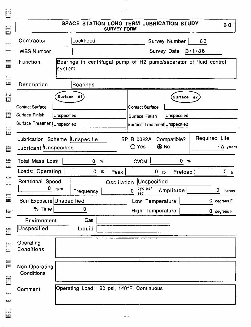
SPACE STATION LONG TERM LUBRICATION STUDYSURVEY FORM
t_
Contractor
WBS Number
Lockheed Survey Number I 60
Survey Date 13/1/86
IF-=._ Function Bearings in centrifugal
system
pump of H2 pump/separator of fluid control
Description IBearings
E_
Contact Surface I
Surface Finish IUnspecified
Surface Treatmenl IUnsPecified
Lubrication Scheme IUnspecifie
Lubricant IUnspecified
:if:
Contact Surface I
Surface Finish IUnspecified
Surface Treatment IUnspecified
SP R 0022A Compatible? Required Life
O Yes (_) No I 1 0 years
Total Mass Loss I 0 % CVCM I 0 O/o
Loads: Operating I 0 Ib Peak I 0 Ib Preload I 0 Ib
Rotational Speed
0 rpm Frequency I
Oscillation IUnspecified
0 cycles/ Amplitude l$ec
0 inches
Sun Exposure IUnspecified
% Time I 0
Low Temperature I
High Temperature I
0 degrees F
0 degrees FL
Environment
_- IUnspecified
GasILiquid I
_- Operating._. Conditions
Non-OperatingConditions
60 psi, 140°F, ContinuousComment
Operating Load:
=
_E
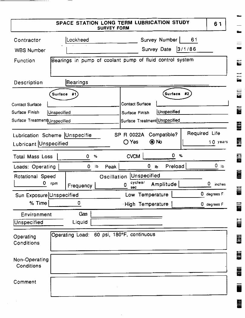
SPACE STATION LONG TERM LUBRICATION STUDYSURVEY FORM
Contractor
WBS Number
JLockheed
!Survey Number J 61
Survey Date 13/1/86I
Function Bearings in pump of coolant pump of fluid control systemz
B
Description IBearingsi
Contact Surface I
Surface Finish IUnspecified
ContactSurface I
Surface Finish IUnspecified
Surface TreatmentlUnspecified
Lubrication Scheme IUnspecifie
Lubricant IUnspecified
Surface TreatmentlUnspecified .
I
SP R 0022A Compatible? III Required LifeO Yes @ NO 1 0 years
W
Rm
M[]
Total Mass Loss J 0 % CVCM I 0 %
Loads:Operating I 0 ,b Peak I 0 ,b Preloadl 0,b[]
Rotational Speed
J 0 rpm
Oscillation IUnsp ecified
Frequency I 0 cycleS/secAmplitude l 0 inches
Sun Exposure JUnspecified Low Temperature I 0 degrees F
mI
=
U
% Time I o
Environment
IUnspecified
Gas I
Liquid I
• High Temperature I
60 psi, 180°F, continuous
0 degrees FF--==l
i
iOperatingConditions
Operating Load:[]I
Non-OperatingConditions
ilJI
Comment
|
li
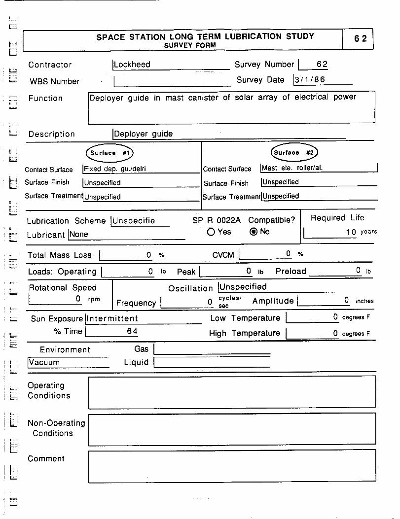
L
LSPACE STATION LONG TERM LUBRICATION STUDY
SURVEY FORMi
Contractor ILockheed
WBS Number I
Survey Number I 62
Survey Date 13/1/86
Function Deployer guide in mast canister of solar array of electrical power
Description IDeployer guide
Contact Surface
|_ Surface Finishf,..J
LJ
IFixed dep. gu./delri
IUnspecified
Contact Surface
Surface Finish
IMast ele. roller/al.
IUnspecified
Surface Treatment_Unspecified
Lubrication Scheme IUnspecifie
Lubricant iNone
Surface Treatmentl Unspecified
SP R 0022A Compatible?
: OYes (_)No
Required Life
1 0 years
Total Mass Loss I 0 % CVCM I 0 O/o
Loads:OperatingI 0 ,o P_kl 0 ,_ P_loa_l 0,oi _ Rotational Speed
I 0 rpm
Oscillation IUnspec ified
Frequency I 0 secCyCies/Amplitude l 0 inches
Sun Exposurell ntermittent
% Time I 64
Environment
IVacuum
GasILiquid [
Low Temperature !
High Temperature I
0 degrees F
0 degrees F
; - Operating=_ Conditionsr,,,=_.,,
F==:
Non-OperatingConditions
Commenti i!I J ;;
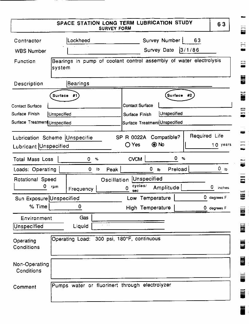
m
SPACE STATION LONG TERM LUBRICATION STUDYSURVEY FORM
63
ii
Contractor
WBS Number
Function
Description
iLockheed
ISurvey Number I 63
Survey Date 13/ 1 / 8 6
Bearings
s.!stem
in pump of coolant control assembly of water electrolysis
IBearings
= =
i
I
m
i
Contact Surface 1
Surface Finish IUnspecified
3ontact Surface I
Surface Finish lUnspec ified
Surface Treatmen_ Unspecified Surface TreatmentlUnspecified
Lubrication Scheme IUnspecifie
Lubricant iUnspecified
SP R 0022A Compatible?
O Yes _) No
Required Life
I 1 0 years
m
J
mu
z
Total Mass Loss I 0 % CVCMI 0 %
Loads: Operating I 0 Jb Peak I 0 Ib Preload I 0 Ib
Rotational Speed
I 0 rpm Frequency I
Oscillation lUnspec ified
0 cycles/ Amplitude !$ec
0 inches
Sun ExposureiUnspecified Low Temperature I 0 degrees F
m
w
m
!
% Time ! 0 High Temperature I
Environment GasI
0 degrees Fi i = ====
!
IUnspecified Liquid I i
U
Operating Operating Load: 300 psi, 180°F, continuous
Conditions
Non-Operating
Conditions
Comment Pumps water or fluorinert through electrolyzer
umi
i
i
i
i
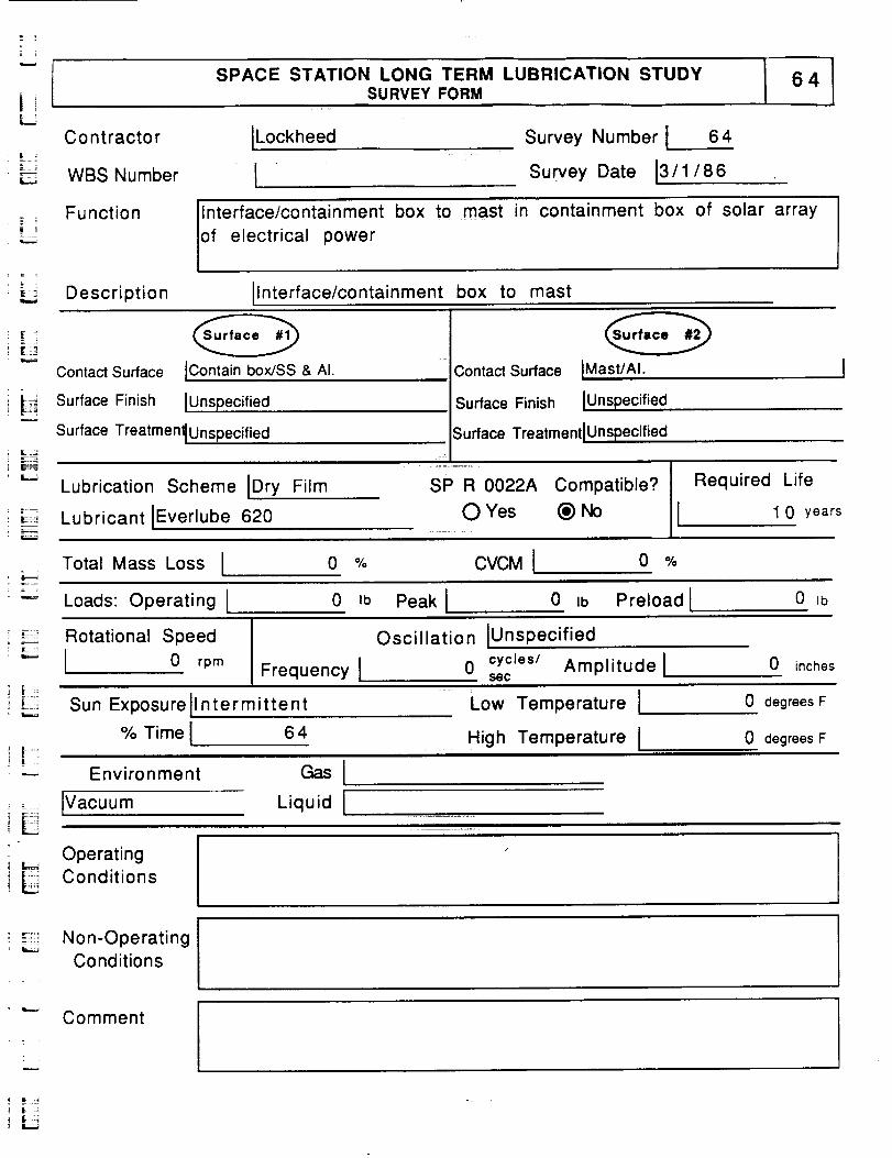
SPACE STATION LONG TERM LUBRICATION STUDYSURVEY FORM
C o nt racto r ILockheed=_ :
_:_:_, WBS Number I
Survey Number I 64
Survey Date 13/1/86
== .
L _
Function Ilnterface/containment box to mast in containment box of solar array
of electrical power
Description Ilnterface/containment box to mast
i=.=._
w
IContain box/SS & AI.Contact Surface
Surface Finish IUnspecified
Surface TreatmentlUnspecified
Contact Surface IMast/Al.
Surface Finish IUnspecified
Surface TreatmentlUnspecified
Lubrication Scheme IDry Film
Lubricant IEverlube 620
SP R 0022A Compatible?
O Yes _) No
Total Mass Loss I 0 % CVCMI 0 %
Required Life
I 1 0 years
Loads: Operating I 0 Ib Peak I 0 Ib Preload I 0 Ib
' _ Rotational Speed
; _ [ 0 rpmFrequency I
Oscillation lUnspec ified
0 cycles/ Amplitude lsec
0 inches
, =
r :
E
Sun Exposurell ntermittent
% Time I 6 4
Environment
[Vacuum
Operating
_ Conditions
Liquid I
ril]
Low Temperature I
High Temperature I
0 degrees F
0 degrees F
m! .......
: -_::_:_Non-OperatingConditions
Comment
! E :
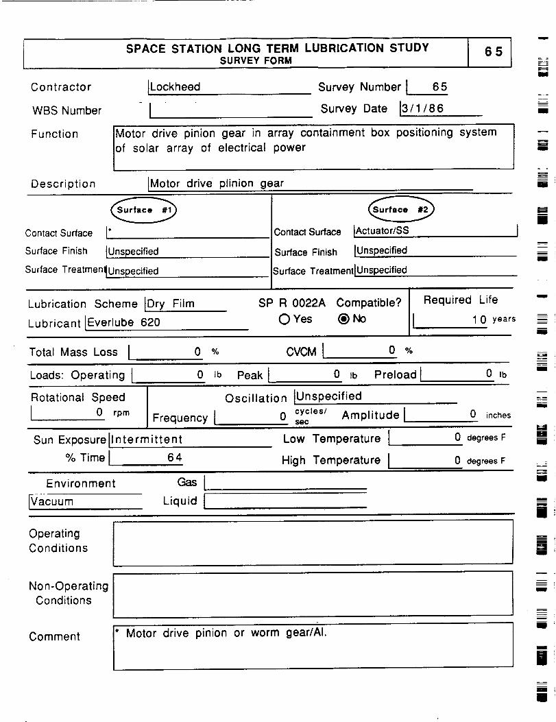
SPACE STATION LONG TERM LUBRICATION STUDYSURVEY FORM
I
Contractor
WBS Number
Function
Description
ILockheed Survey Number I 65
Survey Date 13/1/ 8 6
Motor drive pinion gear in array containment box positioning system
of solar array of electrical power
IMotor drive plinion gear
li
IIII
= =
li
Contact Surface I*
Surface Finish IUnspecified
Surface Treatmen_ Unspecified
Contact Surface IActuator/SS
Surface Finish IUnspecified
Surface TreatmentlUnspecified
I===lm
i
Will
Lubrication Scheme tDry Film
Lubricant IEverlube 620
SP R 0022A Compatible?
O Yes (_) No
Required Life
I 1 0 years
W
l
Total Mass Loss I 0 % CVCMI o %
Loads: Operating[ 0 ,b Peak I 0 tb Preload I 0 ,bMll
Rotational Speed
I 0 rpm Frequency I
Sun Exposureilntermittent
% Time I 6 4
Environment Gas I
IVacuum Liquid I
Oscillation IUnspec ified
0 cycles/ Amplitude lsec
Low Temperature I
High Temperature I
0 inches
0 degrees F
0 degrees F
_-=
i
OperatingConditions
==,.l
mi
Non-OperatingConditions
Comment
I Motor drive pinion or worm gear/AI.
m
Illl
mI
II
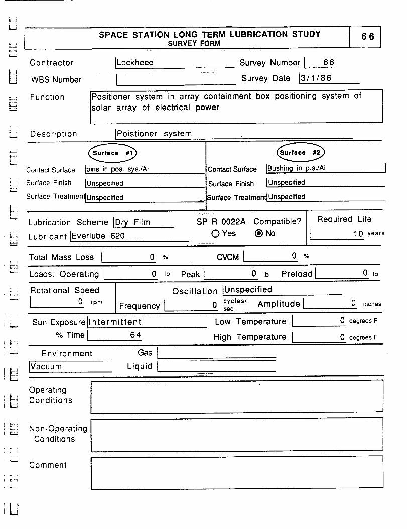
f i
SPACE STATION LONG TERM LUBRICATION STUDYSURVEY FORM
b,..,..
Co nt racto r ILockheed
WBS Number I
Survey Number I 66
Survey Date 13/1/86
= = Function Positioner system in array containment box positioning system of
solar array of electrical power
lii= Description iPoistioner system
L_
= .
L_
Contact Surface
Surface Finish
Ipins in pos. sys./AI
lUnspecified
Contact Surface
Surface Finish
iBushing in p.s./AI
iUnspecified
Surface TreatmentlUnspecified
Lubrication Scheme iDry Film
Lubricant IEverlube 620
= Surface TreatmentiUnspecified
i
SP R 0022A Compatible?
O Yes (_) No
Required Life
I 1 0 years
Total Mass Loss I 0 % CVCM I 0 o/_
Loads: Operating I 0 Ib Peak I 0 Ib Preload I 0 Ib
Rotational Speed
I 0 rpm
Oscillation IUnspecified
Frequency I 0 cycleS/secAmplitude l 0 inches
Sun Exposureilntermittent
% Time I 6 4
Low Temperature I
High Temperature I
0 degrees F
0 degrees F
LEnvironment GasI
Ivacuum Liquid I
Operating}=_ ConditionsL
: =
_-" Non -OperatingConditions
= : ;
Comment
L
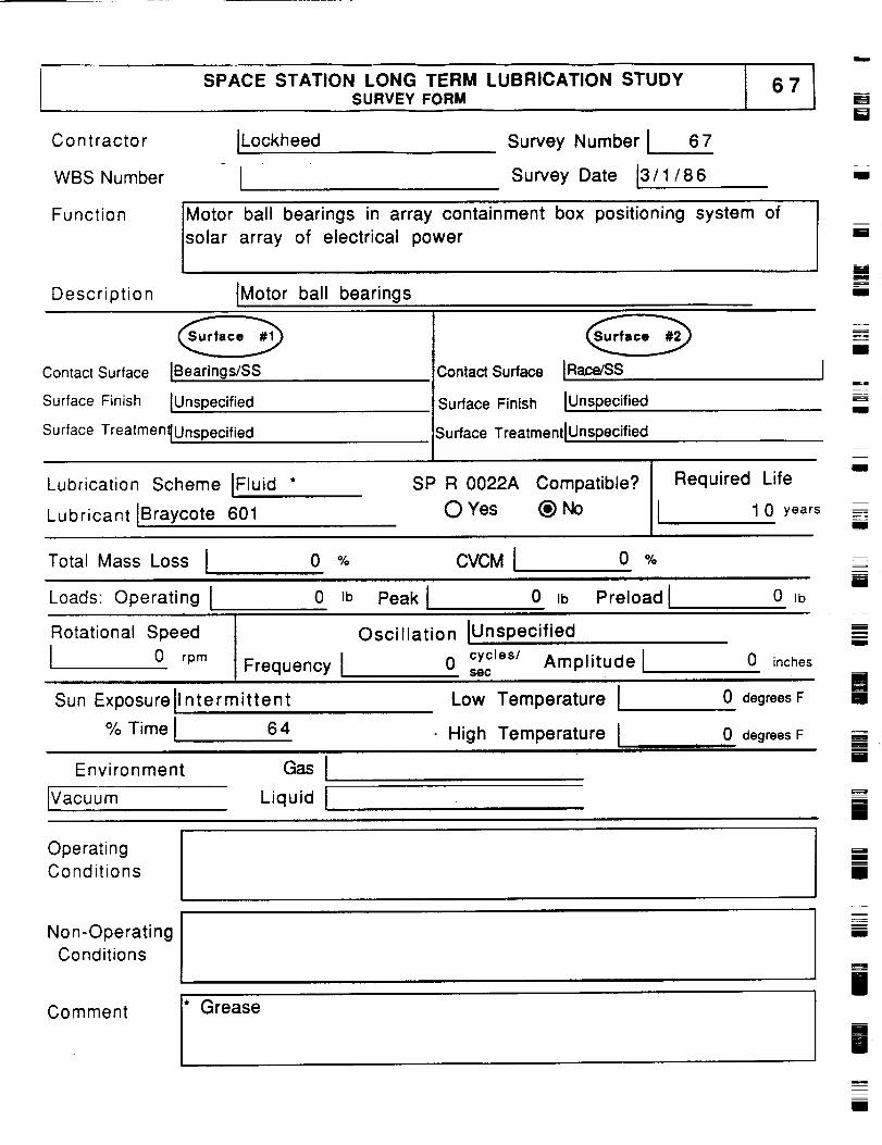
,,,,
SPACE STATION LONG TERM LUBRICATION STUDYSURVEY FORM
N
Contractor
WBS Number
ILockheed Survey Number ! 67
Survey Date 13/1/86
Function Motor ball bearings in array containment box positioning system of
solar array of electrical power
Description JMotor ball bearings
Contact Surface IBearings/SS
Surface Finish IUnspecified
Surface TreatmenlUnspecified
Lubrication Scheme IFluid *
Contact Surface IRace/SS
Surface Finish IUnspecified
;urface TreatmentlUnspecified
SP R 0022A Compatible?
II RequiredLubricant JBraycote 601 0 Yes (_) No
Life
1 0 years
Total Mass Loss I 0 % CVCMI o %
u
ii
I!
II
lii
I
II
Iil
Loads Operating I 0 Ib Peak I 0 Ib Preload I 0 Ib
Rotational Speed
I 0 rpm Frequency I
Oscillation IUnsp ecified
0 cycles/ Amplitude Jsec
0 inches
l
1Sun ExposureJlntermittent
% Time I
Environment
JVacuum
64
Liquid I
Low Temperature I
High Temperature I ....
0 degrees F
0 degrees Fii
i
i i
i
Im
mm
Operating
Conditions
Non-OperatingConditions
Comment
* Grease
ill
II!i
im
l!
mIll

SPACE STATION LONG TERM LUBRICATION STUDYSURVEY FORM
L
C o nt racto r ILockheed
WBS Number I
Survey Number I 68
Survey Date 13/1/86
Function Latch and release mechanism in array containment box positioning
system of solar array of electrical power
Description ILatch and release mechanism
i _--4
Contact Surface ILatch/AI
Surface Finish IUnspecified
Surface Treatmen_ Unspecified
Lubrication Scheme IDry Film
Lubricant IEverlube 620
Contact Surface IRelease/AI
Surface Finish lUnspecified
;urface Treatmentl Unspecified
SP R 0022A Compatible?
O Yes (_) No
Required Life
1 0 years
Total Mass Loss I 0 % CVCM I 0 %
'--' Loads: Operating 0 ,b Peak I 0 ,b Preload ! 0 lb
,L=_ Rotational Speed
i _ ! 1 0 rpm Frequency I
Oscillation IUnsp ecified
0 cycles/ Amplitude lsec
0 inches
[ ;.--,
[ L-.
L
Sun Exposure
% Time
ntermittent
64
Low Temperature I
High Temperature I
Environment Gas I
Vacuum Liquid I
0 degrees F
0 degrees F
LOperatingConditions
Non-Operating
Conditions
Mechanism holds box positionI L.J
.-,=_
Comment
L
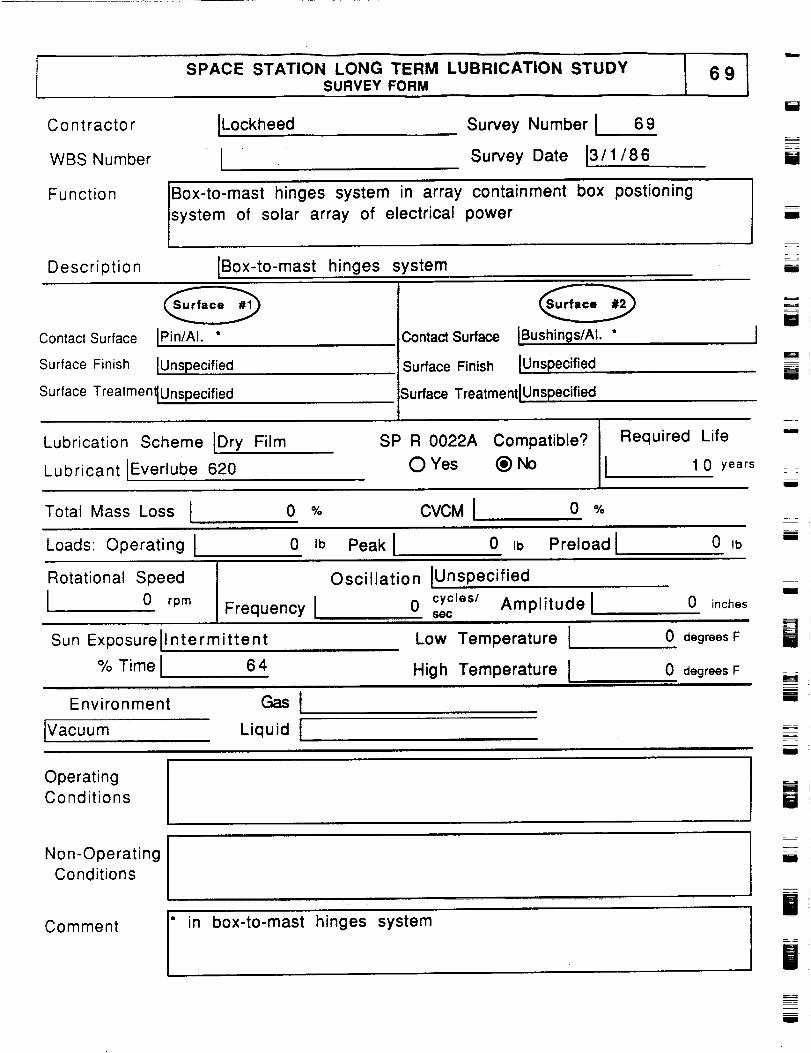
SPACE STATION LONG TERM LUBRICATION STUDYSURVEY FORM
C o nt racto r ILockheed
WBS Number I
Function Box-to-mast hinges system in array
system of solar array of electrical
Survey Number I 69
Survey Date 13/1/86
Description IBox-to-mast hinges system
containment box
power
postioning
i
i
I
i
Contact Surface
Surface Finish
IPin/AI. *
IUnspecified
ContactSurface
Surface Finish
IBush, in_s/Ai. *
IUns ecifiedpi
Surface TreatmenlUnspecified Surface TreatmentlUnspecified
Lubrication Scheme IDry Film
Lubricant IEverlube 620
SP R 0022A Compatible?
O Yes _
Required Life
1 0 years
__ =_
[]
M
I
i
I
Total Mass Loss I 0 % CVCMI 0
Loads: Operating I 0 Ib Peak I 0 Ib Preload ! 0 IbmI
Rotational Speed
I 0 rpm Frequency I
Oscillation IUnspec ified
0 cycles/ Amplitude lSOC
0 inchesI
H
Sun Exposureli ntermittent
% Time I 6 4
Low Temperature i
High Temperature I
Environment
IVacuum
GasILiquid I
0 degrees F
0 degrees F
[]
Mi
rl
I
OperatingConditions []
Non-OperatingConditions
Comment
t
in box-to-mast hinges system
m
I
i
B
m
mw
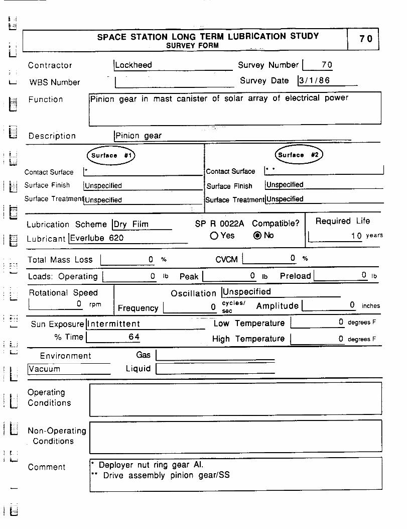
SPACE STATION LONG TERM LUBRICATION STUDYSURVEY FORM
70
C o n t racto r ILockheed
° I,-- WBS Number
Survey Number I 70
Survey Date 13/ 1 / 86
FunctionPinion gear in mast canister of solar array of electrical power
U Description IPinion gear
Contact Surface [*
-i_ Surface Finish IUnspecified
Surface Treatmen_Unspecified
ContactSurface I* *
Surface Finish lUnsp ecified
Surface TreatmentlUnspecified
Lubrication Scheme IDry Film
Lubricant Everlube 620
SP R 0022A Compatible?
0 Yes (_)No
Required Life
I 1 0 years
Total Mass Loss I 0 % CVCM I 0 %
Loads: Operating I 0 Ib Peak I 0 Ib Preload I 0 Ib
Rotational Speed
i L I 0 rprnFrequency I
Oscillation IUnsp ecified
0 cycJes/ Amplitude lS6C
0 inches
L
Sun Exposurell ntermittent
% Time I 6 4
Low Temperature I
....... High Temperature I
Environment
IVacuum
Ga,ILiquid I
0 degrees F
0 degrees F
OperatingConditions
[ii iNon-Operating
Conditions
Comment
* Deployer nut ring gear AI.** Drive assembly pinion gear/SS
I
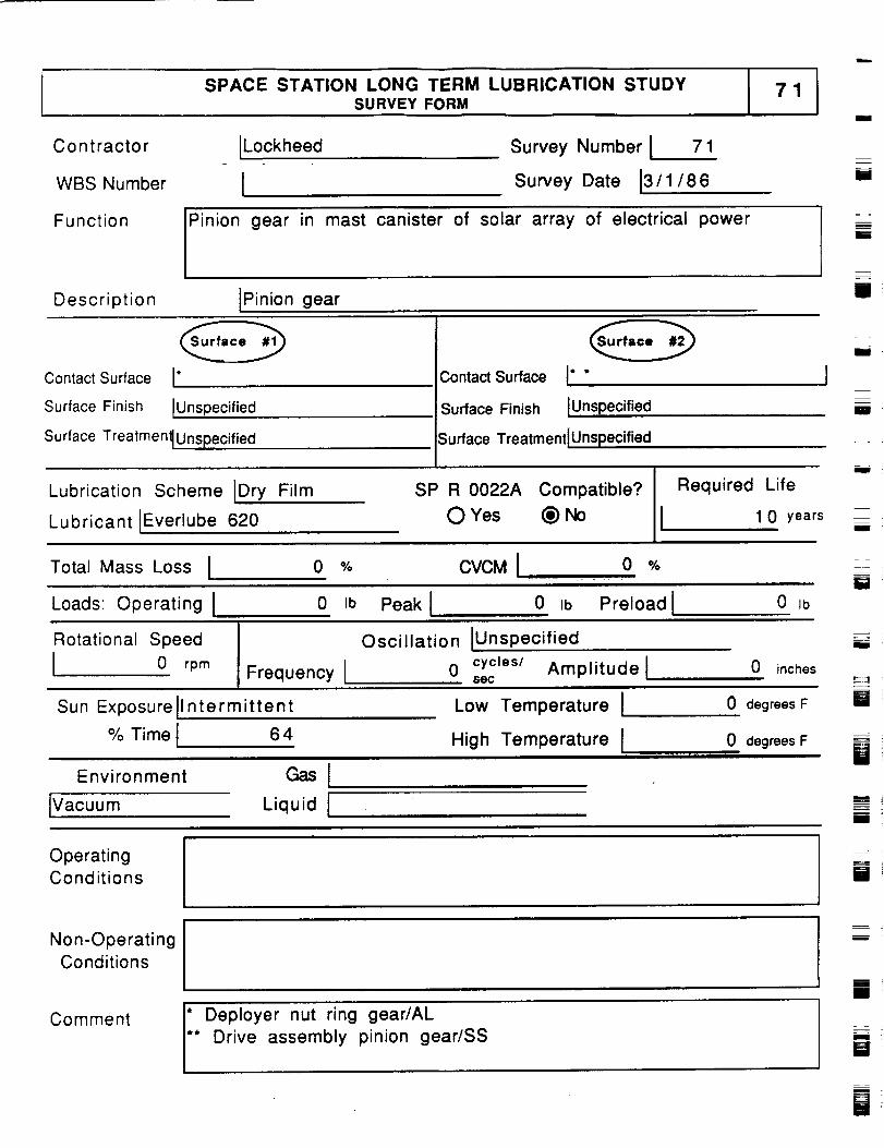
SPACE STATION LONG TERM LUBRICATION STUDYSURVEY FORM
i
C o n t racto r ILockheed
WBS Number 1
Survey Number I 71
Survey Date 13/1/86U
Function
Pi
nion gear in mast canister of solar array of electrical power
Description IPinion gear
lii
i
Contact Surface [*
Surface Finish [Unspecified
Contact Surface I* *
Surface Finish IUnspecified
Surface Treatmen_ Unspecified Surface Treatment[Unspecified
Lubrication Scheme IDry Film
Lubricant [Everlube 620
SP R 0022A Compatible?
O Yes _
Required Life
I 1 0 years
i
i
m
m
Ill
Total Mass Loss I 0 %
Loads: Operating I 0 Ib
CVCMI. 0 %
Peak I 0 Ib Preload ! 0 IbI
Rotational Speed
I 0 rpm Frequency I
Oscillation IUnspecified
0 cycles/ Amplitudelsec
0 inches
Sun Exposurell ntermittent Low Temperature I 0 degrees F W
% Time i 6 4 High Temperature Iiii
Environment
IVacuum
GaslLiquid I
0 degrees F
li
OperatingConditions i
Non-OperatingConditions
Comment
* Deployer nut ring gear/AL** Drive assembly pinion gear/SS
iw
--.__=
i
lib
[]
=
Biiii
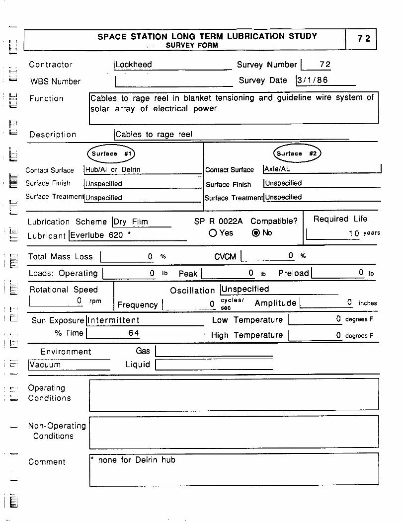
SPACE STATION LONG TERM LUBRICATION STUDY_. SURVEY FORM
Co nt racto r ILockheed
WBS Number I
Survey Number I 72
Survey Date 13/1/86
iT...;
Function ICables to rage reel in blanket tensioning and guideline wire system of
solar array of electrical power
Description ICables to rage reel
E
!.....
Contact Surface IHub/AI or Delrin
Surface Finish [Unspecified
Surface Treatment tUnspecified
Lubrication Scheme IDry Film
Lubricant IEverlube 620 *
Contact Surface IAxle/AL
--I Surface Finish IUnspec ified
i
I
isu rfae-'e TreatmentlUnspecifie, d
SP R 0022A Compatible?
O Yes (_)No
Required Life
I 1 0 years
Total Mass Loss I 0 % CVCMI 0
LJI
Loads Operating I
Rotational Speed
0 rpm
0 Ib
Frequency I
Peak I 0 Ib Preload I 0 Ib
Oscillation IUnspec ified
0 cycles/ Amplitude I 0 inchessec
Sun Exposurell ntermittent
% Time I
Environment
IVacuum
64
Liquid I
Low Temperature I
High Temperature I
0 degrees F
0 degrees F
_, OperatingConditions
Non-OperatingConditions
i
Comment
* none for Delrin hub
E
FIE

I
I
I
_D
m_m
m
i
u _
mM
WIB
mm
m
I
_m
i
imI
mmmm
m
mmmRII
|mmm
R