Embed Size (px)
Citation preview
3M™ Cold Shrink QT-III Silicone Rubber Indoor Termination KitWith High-K Stress Relief
For Tape Shielded, Wire Shielded and UniShield® Cable
7620-T-95
InstructionsIEEE Std. No. 48Class 1 Termination5/8 kV Class95 kV BIL
F CAUTION Working around energized systems may cause serious injury or death. Installation should
be performed by personnel familiar with good safety practice in handling electrical equipment. De-energize and ground all electrical systems before installing product.
March 201378-8113-5098-8 Rev F 3
2 78-8113-5098-8 Rev F
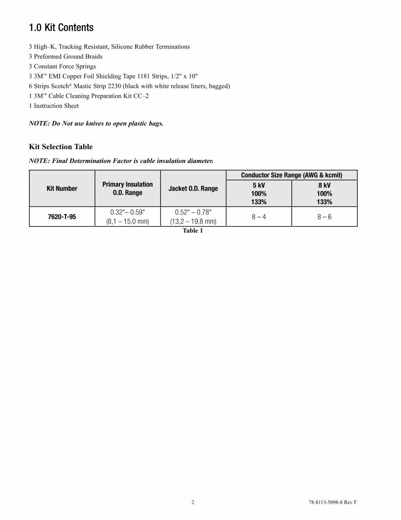
1.0 Kit Contents
3 High–K, Tracking Resistant, Silicone Rubber Terminations3 Preformed Ground Braids3 Constant Force Springs3 3M™ EMI Copper Foil Shielding Tape 1181 Strips, 1/2" x 10"6 Strips Scotch® Mastic Strip 2230 (black with white release liners, bagged)1 3M™ Cable Cleaning Preparation Kit CC–21 Instruction Sheet
NOTE: Do Not use knives to open plastic bags.
Kit Selection Table
NOTE: Final Determination Factor is cable insulation diameter.
Kit NumberPrimary Insulation
O.D. RangeJacket O.D. Range
Conductor Size Range (AWG & kcmil)5 kV100%133%
8 kV100%133%
7620-T-950.32"– 0.59"
(8,1 – 15,0 mm)0.52" – 0.78"
(13,2 – 19,8 mm)8 – 4 8 – 6
Table 1
78-8113-5098-8 Rev F 3
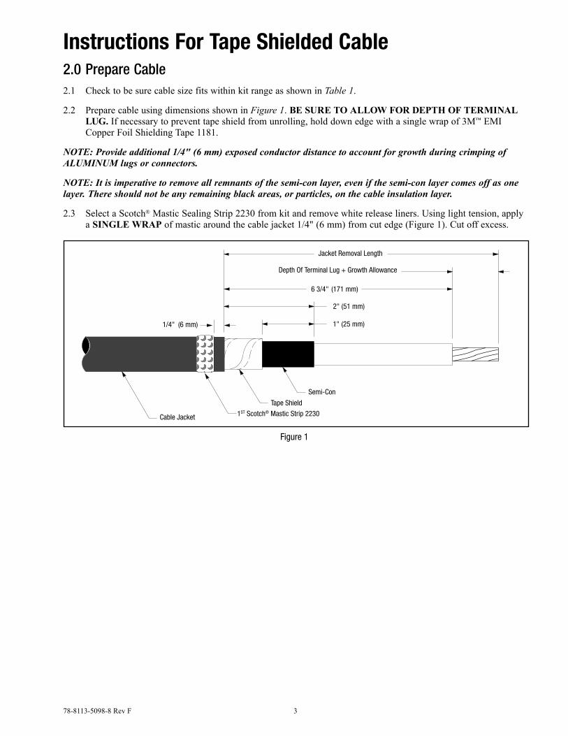
Instructions For Tape Shielded Cable2.0 Prepare Cable2.1 Check to be sure cable size fits within kit range as shown in Table 1.
2.2 Prepare cable using dimensions shown in Figure 1. Be Sure To allow for depTh of Terminal lug. If necessary to prevent tape shield from unrolling, hold down edge with a single wrap of 3M™ EMI Copper Foil Shielding Tape 1181.
NOTE: Provide additional 1/4" (6 mm) exposed conductor distance to account for growth during crimping of ALUMINUM lugs or connectors.
NOTE: It is imperative to remove all remnants of the semi-con layer, even if the semi-con layer comes off as one layer. There should not be any remaining black areas, or particles, on the cable insulation layer.
2.3 Select a Scotch® Mastic Sealing Strip 2230 from kit and remove white release liners. Using light tension, apply a Single wrap of mastic around the cable jacket 1/4" (6 mm) from cut edge (Figure 1). Cut off excess.
Jacket Removal Length
6 3/4" (171 mm)
2" (51 mm)
Semi-Con
Tape Shield
Depth Of Terminal Lug + Growth Allowance
1" (25 mm)
Cable Jacket
1/4" (6 mm)
1ST Scotch® Mastic Strip 2230
Figure 1
4 78-8113-5098-8 Rev F
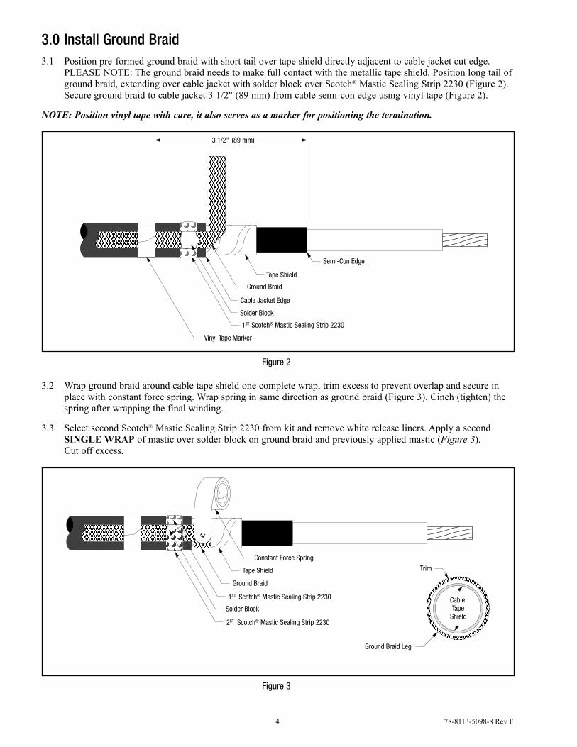
3.0 Install Ground Braid3.1 Position pre-formed ground braid with short tail over tape shield directly adjacent to cable jacket cut edge.
PLEASE NOTE: The ground braid needs to make full contact with the metallic tape shield. Position long tail of ground braid, extending over cable jacket with solder block over Scotch® Mastic Sealing Strip 2230 (Figure 2). Secure ground braid to cable jacket 3 1/2" (89 mm) from cable semi-con edge using vinyl tape (Figure 2).
NOTE: Position vinyl tape with care, it also serves as a marker for positioning the termination.
Tape Shield
Ground Braid
Cable Jacket Edge
Vinyl Tape Marker
Semi-Con Edge
Solder Block
1ST Scotch® Mastic Sealing Strip 2230
3 1/2" (89 mm)
Figure 2
3.2 Wrap ground braid around cable tape shield one complete wrap, trim excess to prevent overlap and secure in place with constant force spring. Wrap spring in same direction as ground braid (Figure 3). Cinch (tighten) the spring after wrapping the final winding.
3.3 Select second Scotch® Mastic Sealing Strip 2230 from kit and remove white release liners. Apply a second Single wrap of mastic over solder block on ground braid and previously applied mastic (Figure 3). Cut off excess.
Tape Shield
Constant Force Spring
Ground Braid
1ST Scotch® Mastic Sealing Strip 2230
Solder Block
2ST Scotch® Mastic Sealing Strip 2230
Ground Braid Leg
Trim
CableTape
Shield
Figure 3
78-8113-5098-8 Rev F 5
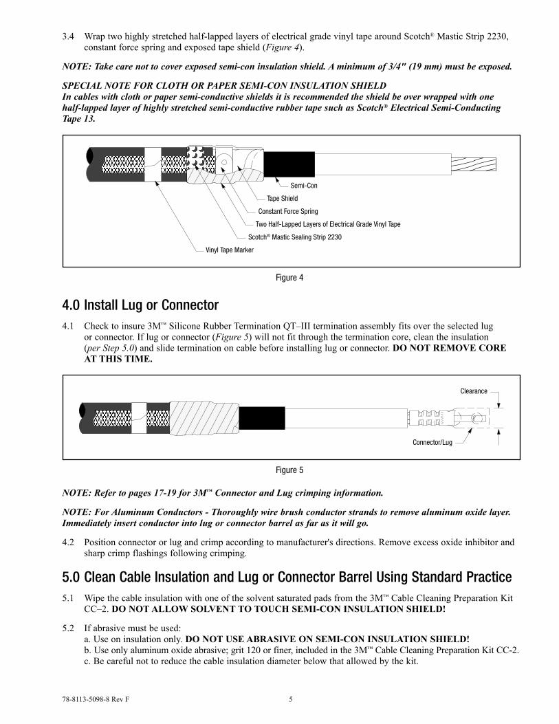
3.4 Wrap two highly stretched half-lapped layers of electrical grade vinyl tape around Scotch® Mastic Strip 2230, constant force spring and exposed tape shield (Figure 4).
NOTE: Take care not to cover exposed semi-con insulation shield. A minimum of 3/4" (19 mm) must be exposed.
SPECIAL NOTE FOR CLOTH OR PAPER SEMI-CON INSULATION SHIELD In cables with cloth or paper semi-conductive shields it is recommended the shield be over wrapped with one half-lapped layer of highly stretched semi-conductive rubber tape such as Scotch® Electrical Semi-Conducting Tape 13.
Semi-Con
Constant Force Spring
Two Half-Lapped Layers of Electrical Grade Vinyl Tape
Tape Shield
Scotch® Mastic Sealing Strip 2230
Vinyl Tape Marker
Figure 4
4.0 Install Lug or Connector4.1 Check to insure 3M™ Silicone Rubber Termination QT–III termination assembly fits over the selected lug
or connector. If lug or connector (Figure 5) will not fit through the termination core, clean the insulation (per Step 5.0) and slide termination on cable before installing lug or connector. do noT remoVe Core aT ThiS Time.
Clearance
Connector/Lug
Figure 5
NOTE: Refer to pages 17-19 for 3M™ Connector and Lug crimping information.
NOTE: For Aluminum Conductors - Thoroughly wire brush conductor strands to remove aluminum oxide layer. Immediately insert conductor into lug or connector barrel as far as it will go.
4.2 Position connector or lug and crimp according to manufacturer's directions. Remove excess oxide inhibitor and sharp crimp flashings following crimping.
5.0 Clean Cable Insulation and Lug or Connector Barrel Using Standard Practice5.1 Wipe the cable insulation with one of the solvent saturated pads from the 3M™ Cable Cleaning Preparation Kit
CC–2. do noT allow SolVenT To TouCh Semi-Con inSulaTion Shield!
5.2 If abrasive must be used: a. Use on insulation only. do noT uSe aBraSiVe on Semi-Con inSulaTion Shield! b. Use only aluminum oxide abrasive; grit 120 or finer, included in the 3M™ Cable Cleaning Preparation Kit CC-2. c. Be careful not to reduce the cable insulation diameter below that allowed by the kit.
6 78-8113-5098-8 Rev F
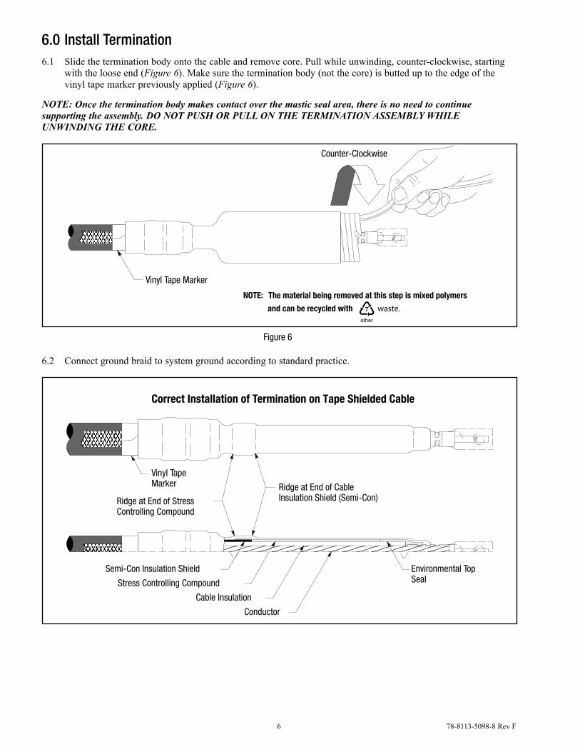
6.0 Install Termination6.1 Slide the termination body onto the cable and remove core. Pull while unwinding, counter-clockwise, starting
with the loose end (Figure 6). Make sure the termination body (not the core) is butted up to the edge of the vinyl tape marker previously applied (Figure 6).
NOTE: Once the termination body makes contact over the mastic seal area, there is no need to continue supporting the assembly. DO NOT PUSH OR PULL ON THE TERMINATION ASSEMBLY WHILE UNWINDING THE CORE.
The material being removed at this step is mixed polymersNOTE:
waste.and can be recycled with
Vinyl Tape Marker
Counter-Clockwise
Figure 6
6.2 Connect ground braid to system ground according to standard practice.
Semi-Con Insulation Shield
Ridge at End of CableInsulation Shield (Semi-Con)Ridge at End of Stress
Controlling Compound
Correct Installation of Termination on Tape Shielded Cable
Vinyl TapeMarker
Environmental TopSeal
Conductor
Cable Insulation
Stress Controlling Compound
78-8113-5098-8 Rev F 7
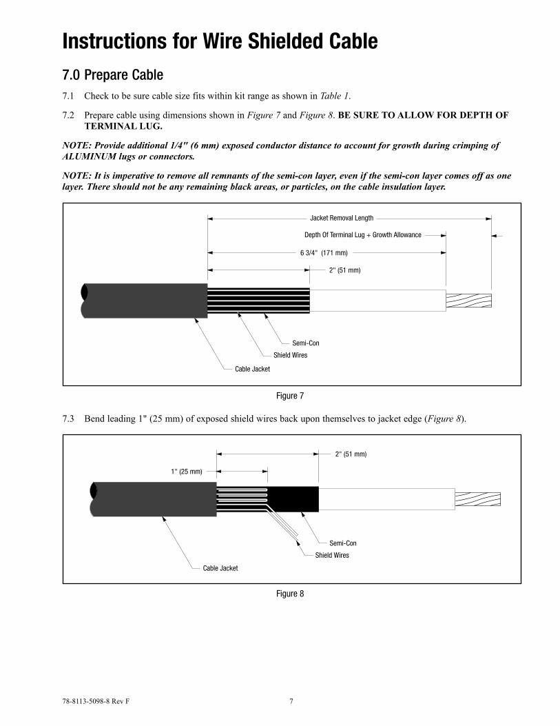
Instructions for Wire Shielded Cable7.0 Prepare Cable7.1 Check to be sure cable size fits within kit range as shown in Table 1.
7.2 Prepare cable using dimensions shown in Figure 7 and Figure 8. Be Sure To allow for depTh of Terminal lug.
NOTE: Provide additional 1/4" (6 mm) exposed conductor distance to account for growth during crimping of ALUMINUM lugs or connectors.
NOTE: It is imperative to remove all remnants of the semi-con layer, even if the semi-con layer comes off as one layer. There should not be any remaining black areas, or particles, on the cable insulation layer.
6 3/4" (171 mm)
Depth Of Terminal Lug + Growth Allowance
2" (51 mm)
Jacket Removal Length
Semi-Con
Shield Wires
Cable Jacket
Figure 7
7.3 Bend leading 1" (25 mm) of exposed shield wires back upon themselves to jacket edge (Figure 8).
2" (51 mm)
1" (25 mm)
Semi-Con
Shield Wires
Cable Jacket
Figure 8
8 78-8113-5098-8 Rev F
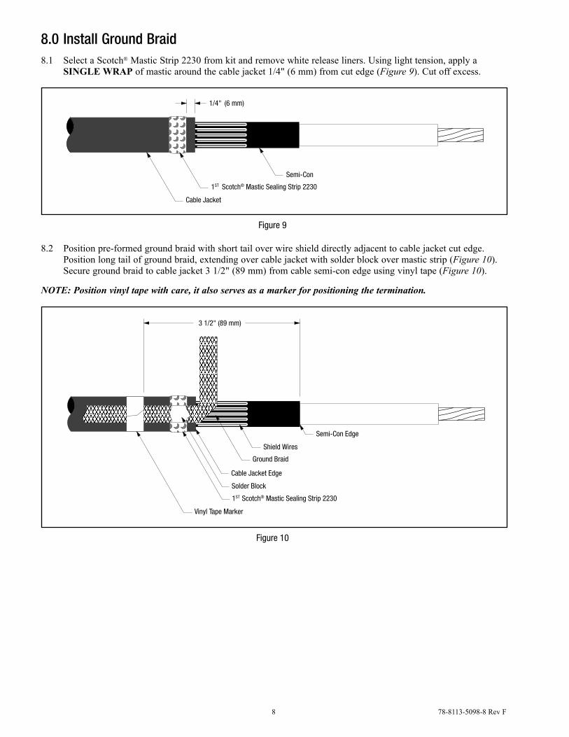
8.0 Install Ground Braid8.1 Select a Scotch® Mastic Strip 2230 from kit and remove white release liners. Using light tension, apply a
Single wrap of mastic around the cable jacket 1/4" (6 mm) from cut edge (Figure 9). Cut off excess.
Semi-Con
1ST Scotch® Mastic Sealing Strip 2230
Cable Jacket
1/4" (6 mm)
Figure 9
8.2 Position pre-formed ground braid with short tail over wire shield directly adjacent to cable jacket cut edge. Position long tail of ground braid, extending over cable jacket with solder block over mastic strip (Figure 10). Secure ground braid to cable jacket 3 1/2" (89 mm) from cable semi-con edge using vinyl tape (Figure 10).
NOTE: Position vinyl tape with care, it also serves as a marker for positioning the termination.
Shield Wires
Ground Braid
Cable Jacket Edge
Vinyl Tape Marker
Semi-Con Edge
Solder Block
1ST Scotch® Mastic Sealing Strip 2230
3 1/2" (89 mm)
Figure 10
78-8113-5098-8 Rev F 9
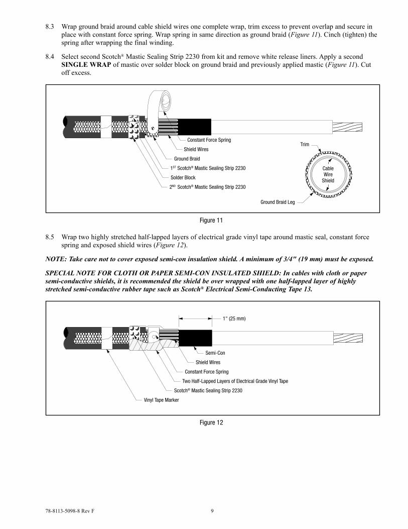
8.3 Wrap ground braid around cable shield wires one complete wrap, trim excess to prevent overlap and secure in place with constant force spring. Wrap spring in same direction as ground braid (Figure 11). Cinch (tighten) the spring after wrapping the final winding.
8.4 Select second Scotch® Mastic Sealing Strip 2230 from kit and remove white release liners. Apply a second Single wrap of mastic over solder block on ground braid and previously applied mastic (Figure 11). Cut off excess.
Shield Wires
Constant Force Spring
Ground Braid
1ST Scotch® Mastic Sealing Strip 2230
Solder Block
2ND Scotch® Mastic Sealing Strip 2230
Ground Braid Leg
Trim
CableWire
Shield
Figure 11
8.5 Wrap two highly stretched half-lapped layers of electrical grade vinyl tape around mastic seal, constant force spring and exposed shield wires (Figure 12).
NOTE: Take care not to cover exposed semi-con insulation shield. A minimum of 3/4" (19 mm) must be exposed.
SPECIAL NOTE FOR CLOTH OR PAPER SEMI-CON INSULATED SHIELD: In cables with cloth or paper semi-conductive shields, it is recommended the shield be over wrapped with one half-lapped layer of highly stretched semi-conductive rubber tape such as Scotch® Electrical Semi-Conducting Tape 13.
Semi-Con
Constant Force Spring
Two Half-Lapped Layers of Electrical Grade Vinyl Tape
Shield Wires
Scotch® Mastic Sealing Strip 2230
Vinyl Tape Marker
1" (25 mm)
Figure 12
10 78-8113-5098-8 Rev F
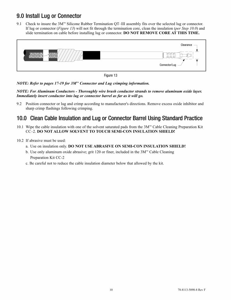
9.0 Install Lug or Connector9.1 Check to insure the 3M™ Silicone Rubber Termination QT–III assembly fits over the selected lug or connector.
If lug or connector (Figure 13) will not fit through the termination core, clean the insulation (per Step 10.0) and slide termination on cable before installing lug or connector. do noT remoVe Core aT ThiS Time.
Clearance
Connector/Lug
Figure 13
NOTE: Refer to pages 17-19 for 3M™ Connector and Lug crimping information.
NOTE: For Aluminum Conductors - Thoroughly wire brush conductor strands to remove aluminum oxide layer. Immediately insert conductor into lug or connector barrel as far as it will go.
9.2 Position connector or lug and crimp according to manufacturer's directions. Remove excess oxide inhibitor and sharp crimp flashings following crimping.
10.0 Clean Cable Insulation and Lug or Connector Barrel Using Standard Practice10.1 Wipe the cable insulation with one of the solvent saturated pads from the 3M™ Cable Cleaning Preparation Kit
CC–2. do noT allow SolVenT To TouCh Semi-Con inSulaTion Shield!
10.2 If abrasive must be used: a. Use on insulation only. do noT uSe aBraSiVe on Semi-Con inSulaTion Shield! b. Use only aluminum oxide abrasive; grit 120 or finer, included in the 3M™ Cable Cleaning Preparation Kit CC-2 c. Be careful not to reduce the cable insulation diameter below that allowed by the kit.
78-8113-5098-8 Rev F 11
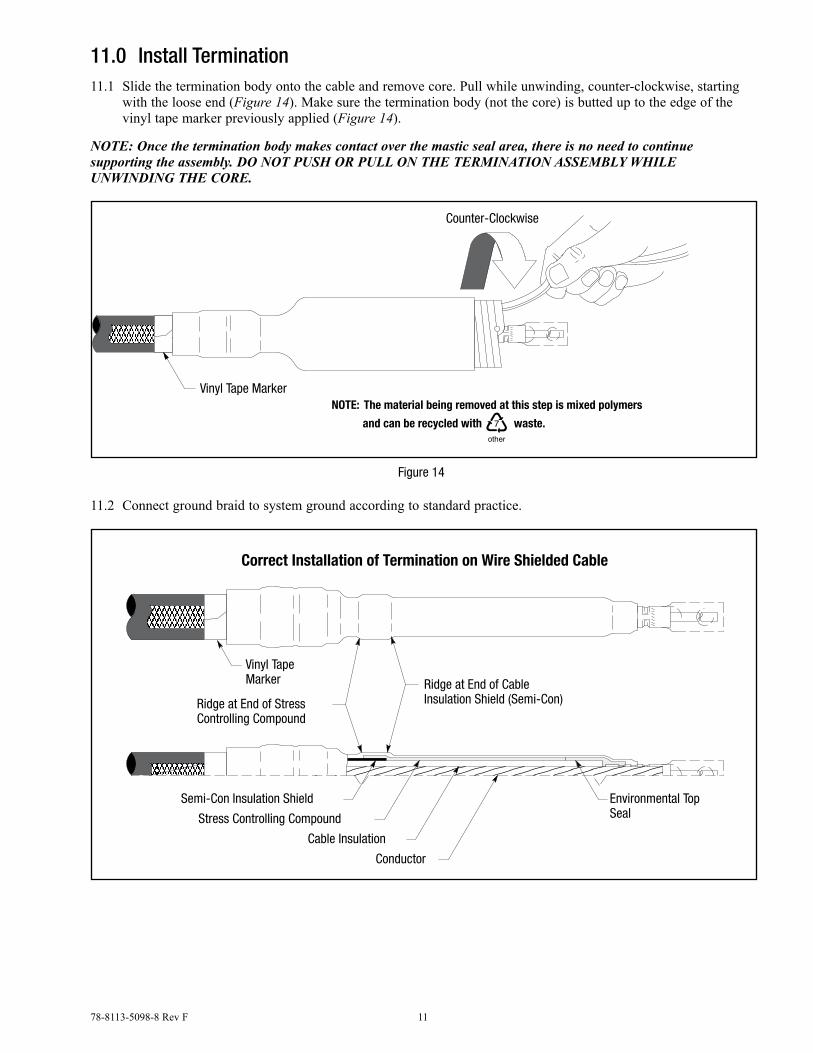
11.0 Install Termination11.1 Slide the termination body onto the cable and remove core. Pull while unwinding, counter-clockwise, starting
with the loose end (Figure 14). Make sure the termination body (not the core) is butted up to the edge of the vinyl tape marker previously applied (Figure 14).
NOTE: Once the termination body makes contact over the mastic seal area, there is no need to continue supporting the assembly. DO NOT PUSH OR PULL ON THE TERMINATION ASSEMBLY WHILE UNWINDING THE CORE.
The material being removed at this step is mixed polymersNOTE:
waste.and can be recycled with
Counter-Clockwise
Vinyl Tape Marker
Figure 14
11.2 Connect ground braid to system ground according to standard practice.
Semi-Con Insulation Shield
Ridge at End of CableInsulation Shield (Semi-Con)Ridge at End of Stress
Controlling Compound
Correct Installation of Termination on Wire Shielded Cable
Vinyl TapeMarker
Environmental TopSeal
Conductor
Cable Insulation
Stress Controlling Compound
12 78-8113-5098-8 Rev F
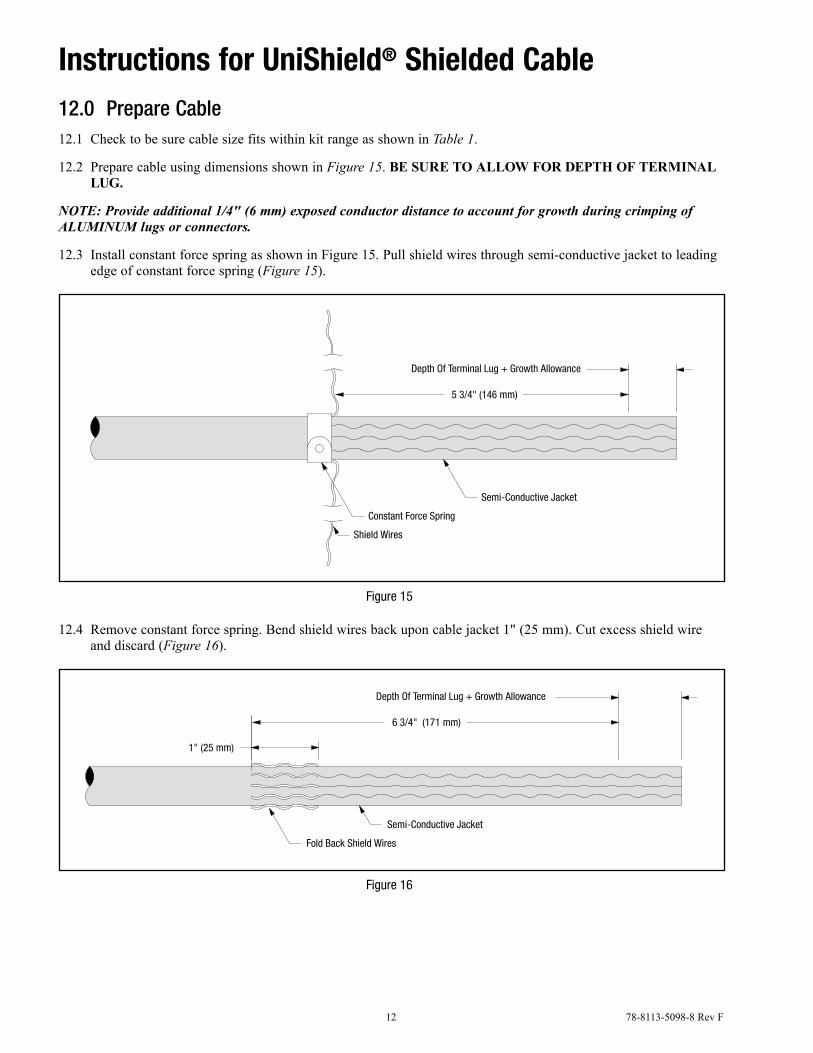
Instructions for UniShield® Shielded Cable12.0 Prepare Cable12.1 Check to be sure cable size fits within kit range as shown in Table 1.
12.2 Prepare cable using dimensions shown in Figure 15. Be Sure To allow for depTh of Terminal lug.
NOTE: Provide additional 1/4" (6 mm) exposed conductor distance to account for growth during crimping of ALUMINUM lugs or connectors.
12.3 Install constant force spring as shown in Figure 15. Pull shield wires through semi-conductive jacket to leading edge of constant force spring (Figure 15).
5 3/4" (146 mm)
Semi-Conductive Jacket
Constant Force Spring
Shield Wires
Depth Of Terminal Lug + Growth Allowance
Figure 15
12.4 Remove constant force spring. Bend shield wires back upon cable jacket 1" (25 mm). Cut excess shield wire and discard (Figure 16).
6 3/4" (171 mm)
1" (25 mm)
Semi-Conductive Jacket
Fold Back Shield Wires
Depth Of Terminal Lug + Growth Allowance
Figure 16
78-8113-5098-8 Rev F 13
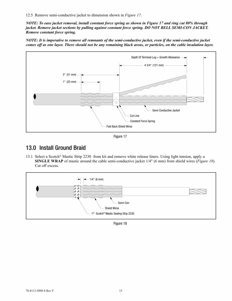
12.5 Remove semi-conductive jacket to dimension shown in Figure 17.
NOTE: To ease jacket removal, install constant force spring as shown in Figure 17 and ring cut 80% through jacket. Remove jacket sections by pulling against constant force spring. DO NOT BELL SEMI-CON JACKET. Remove constant force spring.
NOTE: It is imperative to remove all remnants of the semi-conductive jacket, even if the semi-conductive jacket comes off as one layer. There should not be any remaining black areas, or particles, on the cable insulation layer.
Depth Of Terminal Lug + Growth Allowance
4 3/4" (121 mm)
1" (25 mm)
Semi-Conductive Jacket
Cut Line
Constant Force Spring
Fold Back Shield Wires
2" (51 mm)
Figure 17
13.0 Install Ground Braid13.1 Select a Scotch® Mastic Strip 2230 from kit and remove white release liners. Using light tension, apply a
Single wrap of mastic around the cable semi-conductive jacket 1/4" (6 mm) from shield wires (Figure 18). Cut off excess.
Semi-Con
Shield Wires
1ST Scotch® Mastic Sealing Strip 2230
1/4" (6 mm)
Figure 18
14 78-8113-5098-8 Rev F
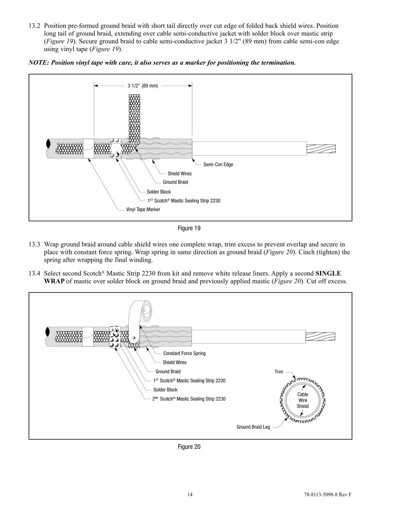
13.2 Position pre-formed ground braid with short tail directly over cut edge of folded back shield wires. Position long tail of ground braid, extending over cable semi-conductive jacket with solder block over mastic strip (Figure 19). Secure ground braid to cable semi-conductive jacket 3 1/2" (89 mm) from cable semi-con edge using vinyl tape (Figure 19).
NOTE: Position vinyl tape with care, it also serves as a marker for positioning the termination.
Shield Wires
Ground Braid
Solder Block
Semi-Con Edge
1ST Scotch® Mastic Sealing Strip 2230
Vinyl Tape Marker
3 1/2" (89 mm)
Figure 19
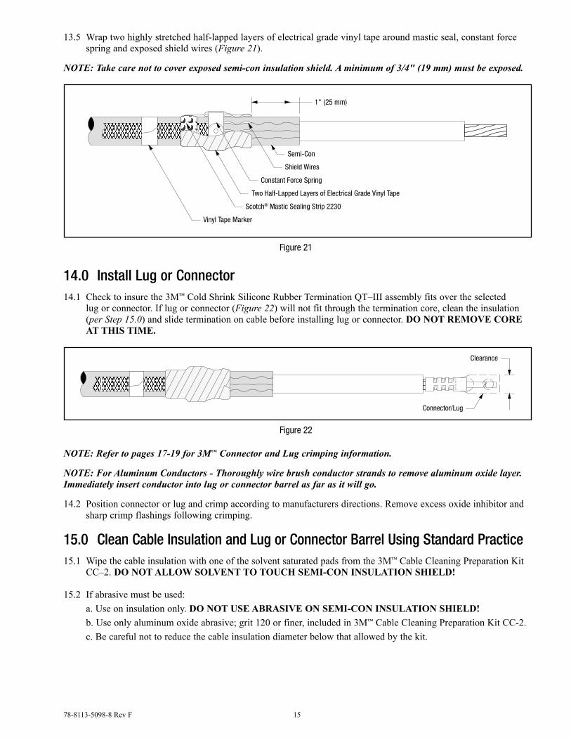
13.3 Wrap ground braid around cable shield wires one complete wrap, trim excess to prevent overlap and secure in place with constant force spring. Wrap spring in same direction as ground braid (Figure 20). Cinch (tighten) the spring after wrapping the final winding.
13.4 Select second Scotch® Mastic Strip 2230 from kit and remove white release liners. Apply a second Single wrap of mastic over solder block on ground braid and previously applied mastic (Figure 20). Cut off excess.
Shield Wires
Constant Force Spring
Ground Braid
1ST Scotch® Mastic Sealing Strip 2230
Solder Block
2ND Scotch® Mastic Sealing Strip 2230
Ground Braid Leg
Trim
CableWire
Shield
Figure 20
78-8113-5098-8 Rev F 15
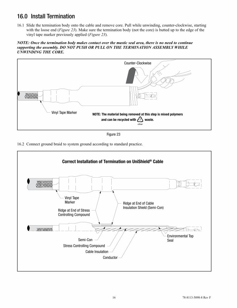
13.5 Wrap two highly stretched half-lapped layers of electrical grade vinyl tape around mastic seal, constant force spring and exposed shield wires (Figure 21).
NOTE: Take care not to cover exposed semi-con insulation shield. A minimum of 3/4" (19 mm) must be exposed.
Semi-Con
Constant Force Spring
Two Half-Lapped Layers of Electrical Grade Vinyl Tape
Shield Wires
Scotch® Mastic Sealing Strip 2230
Vinyl Tape Marker
1" (25 mm)
Figure 21
14.0 Install Lug or Connector14.1 Check to insure the 3M™ Cold Shrink Silicone Rubber Termination QT–III assembly fits over the selected
lug or connector. If lug or connector (Figure 22) will not fit through the termination core, clean the insulation (per Step 15.0) and slide termination on cable before installing lug or connector. do noT remoVe Core aT ThiS Time.
Clearance
Connector/Lug
Figure 22
NOTE: Refer to pages 17-19 for 3M™ Connector and Lug crimping information.
NOTE: For Aluminum Conductors - Thoroughly wire brush conductor strands to remove aluminum oxide layer. Immediately insert conductor into lug or connector barrel as far as it will go.
14.2 Position connector or lug and crimp according to manufacturers directions. Remove excess oxide inhibitor and sharp crimp flashings following crimping.
15.0 Clean Cable Insulation and Lug or Connector Barrel Using Standard Practice15.1 Wipe the cable insulation with one of the solvent saturated pads from the 3M™ Cable Cleaning Preparation Kit
CC–2. do noT allow SolVenT To TouCh Semi-Con inSulaTion Shield!
15.2 If abrasive must be used: a. Use on insulation only. do noT uSe aBraSiVe on Semi-Con inSulaTion Shield! b. Use only aluminum oxide abrasive; grit 120 or finer, included in 3M™ Cable Cleaning Preparation Kit CC-2. c. Be careful not to reduce the cable insulation diameter below that allowed by the kit.
16 78-8113-5098-8 Rev F
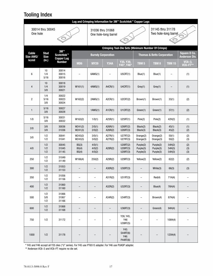
16.0 Install Termination16.1 Slide the termination body onto the cable and remove core. Pull while unwinding, counter-clockwise, starting
with the loose end (Figure 23). Make sure the termination body (not the core) is butted up to the edge of the vinyl tape marker previously applied (Figure 23).
NOTE: Once the termination body makes contact over the mastic seal area, there is no need to continue supporting the assembly. DO NOT PUSH OR PULL ON THE TERMINATION ASSEMBLY WHILE UNWINDING THE CORE.
The material being removed at this step is mixed polymersNOTE:
waste.and can be recycled with
Vinyl Tape Marker
Counter-Clockwise
Figure 23
16.2 Connect ground braid to system ground according to standard practice.
Ridge at End of StressControlling Compound
Semi-Con
Ridge at End of CableInsulation Shield (Semi-Con)
Correct Installation of Termination on UniShield® Cable
Vinyl TapeMarker
Environmental TopSeal
Stress Controlling Compound
Conductor
Cable Insulation
78-8113-5098-8 Rev F 17
Tooling IndexLug and Crimping Information for 3M™ Scotchlok™ Copper Lugs
30014 thru 30045One hole
31036 thru 31068One hole-long barrel
Cable Size AWG/
kcmil
Stud Size(in.)
3M™
Scotchlok™ Copper Lug
Number
Crimping Tool-Die Sets (Minimum Number Of Crimps)
Burndy Corporation Thomas & Betts Corporation Square D Co. Anderson Div.
MD6 MY29 Y34A Y35, Y39, Y45*, Y46* TBM 5 TBM 8 TBM 15 VC6–3,
VC6–FT**
6101/45/16
300143001530016
– 6AWG(1) – U5CRT(1) Blue(1) Blue(1) – (1)
4101/43/8
300183001930021
W161(1) 4AWG(1) A4CR(1) U4CRT(1) Grey(1) Grey(1) – (1)
21/45/163/8
300223002330024
W162(2) 2AWG(1) A2CR(1) U2CRT(2) Brown(1) Brown(1) 33(1) (2)
15/163/8
3002730028
– 1AWG(1) A1CR(1) U1CRT(2) Green(1) Green(1) 37(1) (2)
1/05/163/8
3003130032
W163(2) 1/0(1) A25R(1) U25RT(1) Pink(2) Pink(2) 42H(2) (1)
2/03/83/8
3003631036
W241(2)W241(3)
2/0(1)2/0(2)
A26R(1)A26R(2)
U26RT(2)U26RT(3)
Black(2)Black(3)
Black(2)Black(3)
45(1)45(2)
(1)(2)
3/01/21/2
3004131041
W243(2)W243(3)
3/0(1)3/0(2)
A27R(1)A27R(2)
U27RT(2)U27RT(3)
Orange(2)Orange(3)
Orange(2)Orange(3)
50(1)50(2)
(2)(3)
4/01/21/21/2
300453104531145
BG(3)BG(4)BG(4)
4/0(1)4/0(2)4/0(2)
A28R(2)U28RT(2)U28RT(3)U28RT(3)
Purple(2)Purple(3)Purple(3)
Purple(2)Purple(3)Purple(3)
54H(2)54H(3)54H(3)
(2)(3)(3)
2501/21/2
3104931149
W166(4) 250(2) A29R(2) U29RT(3) Yellow(2) Yellow(2) 62(2) (2)
3001/21/2
3105331153
– – A30R(2) U30RT(3) – White(3) 66(3) (3)
3501/21/2
3105631156
– – A31R(2) U31RT(3) – Red(4) 71H(4) –
4001/21/2
3106031160
– – A32R(2) U32RT(3) – Blue(4) 76H(4) –
5001/25/81/2
310663106731166
– – A34R(2) U34RT(3) – Brown(4) 87H(4) –
6001/21/2
3106831168
– – – U36RT(3) – Green(4) 94H(4) –
750 1/2 31172 – – –Y39, Y45,
Y46U39RT(5)
– – 106H(4) –
1000 1/2 31178 – – –
Y45: S44RT(6)
Y46: P44RT(6)
– – 125H(4) –
* Y45 and Y46 accept all Y35 dies (“U” series). For Y45 use PT6515 adapter. For Y46 use PUADP adapter.** Anderson VC6–3 and VC6–FT require no die set.
31145 thru 31178Two hole-long barrel
18 78-8113-5098-8 Rev F
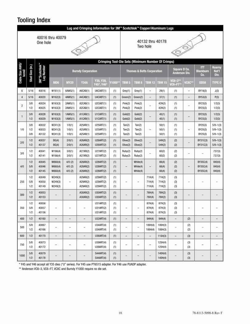
Tooling IndexLug and Crimping Information for 3M™ Scotchlok™ Copper/Aluminum Lugs
40016 thru 40079One hole 40132 thru 40178
Two hole
Cabl
e Si
ze A
WG/
kcm
il
Stud
Siz
e (in
.)
3M™
Scot
chlo
k™
Lug
Num
ber
Crimping Tool-Die Sets (Minimum Number Of Crimps)
Burndy Corporation Thomas & Betts Corporation Square D Co. Anderson Div.
ITTBlackburn
Co.
KearnyNat’lDiv.
MD6 MY29 Y34A Y35, Y39,Y45*, Y46* Y1000** TBM 5 TBM 8 TBM 12 TBM 15 VC6–3**
VC6–FT** VC8C** OD58 TYPE O
6 5/16 40016 W161(1) 6AWG(1) A6CAB(1) U6CABT(1) (1) Grey(1) Grey(1) – 29(1) (1) – BY19(3) J(3)
4 5/16 40020 W162(3) 4AWG(1) A4CAB(1) U4CABT(1) (1) Green(2) Green(2) – 37(1) (1) – BY53(3) P(3)
23/8
1/2
40024
40025
W163(3)
W163(3)
2AWG(1)
2AWG(1)
A2CAB(1)
A2CAB(1)
U2CABT(1)
U2CABT(1)
(1)
(1)
Pink(2)
Pink(2)
Pink(2)
Pink(2)–
42H(2)
42H(2)
(1)
(1)–
BY23(3)
BY23(3)
1/2(3)
1/2(3)
13/8
1/2
40028
40029
W163(3)
W163(3)
1AWG(1)
1AWG(1)
A1CAR(1)
A1CAR(1)
U1CART(1)
U1CART(1)
(1)
(1)
Gold(2)
Gold(2)
Gold(2)
Gold(2)–
45(1)
45(1)
(1)
(1)–
BY23(3)
BY23(3)
1/2(3)
1/2(3)
1/0
3/8
1/2
3/8
40032
40033
40132
W241(3)
W241(3)
W241(3)
1/0(1)
1/0(1)
1/0(1)
A25AR(1)
A25AR(1)
A25AR(1)
U25ART(1)
U25ART(1)
U25ART(1)
(1)
(1)
(1)
Tan(2)
Tan(2)
Tan(2)
Tan(2)
Tan(2)
Tan(2)
–
50(1)
50(1)
50(1)
(1)
(1)
(1)
–
BY25(3)
BY25(3)
BY25(3)
5/8–1(3)
5/8–1(3)
5/8–1(3)
2/01/2
1/2
40037
40137
BG(4)
BG(4)
2/0(1)
2/0(1)
A26AR(2)
A26AR(2)
U26ART(2)
U26ART(2)
(1)
(1)
Olive(2)
Olive(2)
Olive(2)
Olive(2)–
54H(2)
54H(2)
(2)
(2)–
BY31C(3)
BY31C(3)
5/8–1(3)
5/8–1(3)
3/01/2
1/2
40041
40141
W166(4)
W166(4)
3/0(1)
3/0(1)
A27AR(2)
A27AR(2)
U27ART(2)
U27ART(2)
(1)
(1)
Ruby(2)
Ruby(2)
Ruby(2)
Ruby(2)–
60(2)
60(2)
(2)
(2)– –
737(3)
737(3)
4/0
1/2
5/8
1/2
40045
40046
40145
W660(4)
W660(4)
W660(4)
4/0 (2)
4/0 (2)
4/0 (2)
A28AR(2)
A28AR(2)
A28AR(2)
U28ART(2)
U28ART(2)
U28ART(2)
(1)
(1)
(1)
–
White(4)
White(4)
White(4)
–
66(4)
66(4)
66(4)
(2)
(2)
(2)
–
BY35C(4)
BY35C(4)
BY35C(4)
840(4)
840(4)
840(4)
250
1/2
5/8
1/2
40049
40050
40149
W249(3)
W249(3)
W249(3)
–
A29AR(2)
A29AR(2)
A29AR(2)
U29ART(2)
U29ART(2)
U29ART(2)
(1)
(1)
(1)
– –
71H(4)
71H(4)
71H(4)
71H(2)
71H(2)
71H(2)
(3)
(3)
(3)
– – –
3001/2
1/2
40053
40153– –
A30AR(2)
A30AR(2)
U30ART(2)
U30ART(2)
(1)
(1)– –
76H(4)
76H(4)
76H(2)
76H(2)
(3)
(3)– – –
350
1/2
5/8
1/2
40056
40057
40156
– – –
U31ART(2)
U31ART(2)
U31ART(2)
(1)
(1)
(1)
– –
87H(4)
87H(4)
87H(4)
87H(3)
87H(3)
87H(3)
(3)
(3)
(3)
– – –
400 1/2 40160 – – – U32ART(4) (1) – – 94H(4) 94H(4) – (2) – –
5005/8
1/2
40067
40166– – –
U34ART(4)
U34ART(4)
(1)
(1)– –
106H(4)
106H(4)
106H(3)
106H(3)–
(2)
(2)– –
600 1/2 40170 – – – U36ART(4) (1) – – – 115H(3) – (3) – –
7505/8
1/2
40073
40172– – –
U39ART(4)
U39ART(4)
(1)
(1)– – –
125H(4)
125H(4)–
(3)
(3)– –
10005/8
1/2
40079
40178– – –
S44ART(4)
S44ART(4)
(1)
(1)– – –
140H(4)
140H(4)–
(3)
(3)– –
* Y45 and Y46 accept all Y35 dies (“U” series). For Y45 use PT6515 adapter. For Y46 use PUADP adapter.** Anderson VC6–3, VC6–FT, VC8C and Burndy Y1000 require no die set.
78-8113-5098-8 Rev F 19
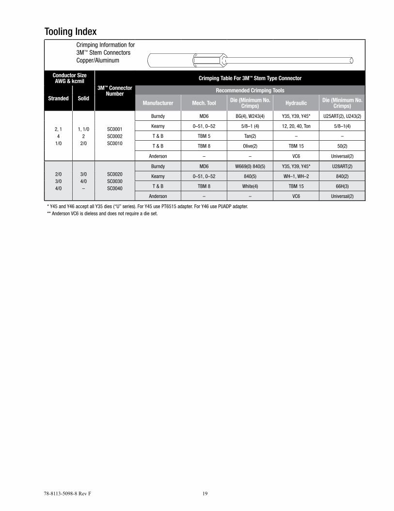
Tooling IndexCrimping Information for3M™ Stem ConnectorsCopper/Aluminum
Conductor SizeAWG & kcmil
3M™ ConnectorNumber
Crimping Table For 3M™ Stem Type Connector
Stranded SolidRecommended Crimping Tools
Manufacturer Mech. Tool Die (Minimum No. Crimps) Hydraulic Die (Minimum No.
Crimps)
2, 14
1/0
1, 1/02
2/0
SC0001 SC0002SC0010
Burndy MD6 BG(4), W243(4) Y35, Y39, Y45* U25ART(2), U243(2)
Kearny 0–51, 0–52 5/8–1 (4) 12, 20, 40, Ton 5/8–1(4)
T & B TBM 5 Tan(2) – –
T & B TBM 8 Olive(2) TBM 15 50(2)
Anderson – – VC6 Universal(2)
2/03/04/0
3/04/0–
SC0020SC0030SC0040
Burndy MD6 W669(0) 840(5) Y35, Y39, Y45* U28ART(2)
Kearny 0–51, 0–52 840(5) WH–1, WH–2 840(2)
T & B TBM 8 White(4) TBM 15 66H(3)
Anderson – – VC6 Universal(2)
* Y45 and Y46 accept all Y35 dies (“U” series). For Y45 use PT6515 adapter. For Y46 use PUADP adapter.** Anderson VC6 is dieless and does not require a die set.
3M, Scotch and Scotchlok are trademarks of 3M Company. UniShield is a trademark of General Cable Technologies Corporation.
Important NoticeAll statements, technical information, and recommendations related to 3M's products are based on information believed to be reliable, but the accuracy or completeness is not guaranteed. Before using this product, you must evaluate it and determine if it is suitable for your intended application. You assume all risks and liability associated with such use. Any statements related to the product which are not contained in 3M's current publications, or any contrary statements contained on your purchase order shall have no force or effect unless expressly agreed upon, in writing, by an authorized officer of 3M.
Warranty; Limited Remedy; Limited Liability. This product will be free from defects in material and manufacture at the time of purchase. 3M MAKES NO OTHER WARRANTIES INCLUDING, BUT NOT LIMITED TO, ANY IMPLIED WARRANTY OF MERCHANTABILITY OR FITNESS FOR A PARTICULAR PURPOSE.
If this product is defective within the warranty period stated above, your exclusive remedy shall be, at 3M's option, to replace or repair the 3M product or refund the purchase price of the 3M product. Except where prohibited by law, 3M will not be liable for any indirect, special, incidental or consequential loss or damage arising from this 3M product, regardless of the legal theory asserted.
Electrical Markets Division6801 River Place Blvd. Austin, TX 78726-9000 800.245.3573Fax 800.245.0329www.3M.com/electrical
Please Recycle. Printed in USA.© 3M 2013. All Rights Reserved.78-8113-5098-8 Rev F