Embed Size (px)
Citation preview

Product specificationArticulated robot
IRB 6400RF-200/2.5IRB 6400RF-200/2.8M2004

Product specification
Articulated robot3HAC026552-001
Rev.EIRB 6400RF-200/2.5IRB 6400RF-200/2.8
M2004

The information in this manual is subject to change without notice and should not be construed as a commitment by ABB. ABB assumes no responsibility for any errors that may appear in this manual.Except as may be expressly stated anywhere in this manual, nothing herein shall be construed as any kind of guarantee or warranty by ABB for losses, damages to persons or property, fit-ness for a specific purpose or the like.In no event shall ABB be liable for incidental or consequential damages arising from use of this manual and products described herein.This manual and parts thereof must not be reproduced or copied without ABB's written per-mission, and contents thereof must not be imparted to a third party nor be used for any unau-thorized purpose. Contravention will be prosecuted.Additional copies of this manual may be obtained from ABB at its then current charge.
©Copyright 2006 ABB All right reserved.
ABB ABRobotics Products
SE-721 68 VästeråsSweden

Table of Contents
Overview 5
1 Description 7
1.1 Structure . . . . . . . . . . . . . . . . . . . . . . . . . . . . . . . . . . . . . . . . . . . . . . . . . . . . . . . . . . . . . . . . . . . . . . . . .71.1.1 Introduction . . . . . . . . . . . . . . . . . . . . . . . . . . . . . . . . . . . . . . . . . . . . . . . . . . . . . . . . . . . . . . . .71.1.2 Different robot versions . . . . . . . . . . . . . . . . . . . . . . . . . . . . . . . . . . . . . . . . . . . . . . . . . . . . . . .8
1.2 Safety/Standards . . . . . . . . . . . . . . . . . . . . . . . . . . . . . . . . . . . . . . . . . . . . . . . . . . . . . . . . . . . . . . . . .111.2.1 Standards . . . . . . . . . . . . . . . . . . . . . . . . . . . . . . . . . . . . . . . . . . . . . . . . . . . . . . . . . . . . . . . . .11
1.3 Installation . . . . . . . . . . . . . . . . . . . . . . . . . . . . . . . . . . . . . . . . . . . . . . . . . . . . . . . . . . . . . . . . . . . . . .141.3.1 Introduction . . . . . . . . . . . . . . . . . . . . . . . . . . . . . . . . . . . . . . . . . . . . . . . . . . . . . . . . . . . . . . .141.3.2 Operating requirements . . . . . . . . . . . . . . . . . . . . . . . . . . . . . . . . . . . . . . . . . . . . . . . . . . . . . .141.3.3 Mounting the manipulator . . . . . . . . . . . . . . . . . . . . . . . . . . . . . . . . . . . . . . . . . . . . . . . . . . . .15
1.4 Calibration and References . . . . . . . . . . . . . . . . . . . . . . . . . . . . . . . . . . . . . . . . . . . . . . . . . . . . . . . .171.4.1 Fine calibration. . . . . . . . . . . . . . . . . . . . . . . . . . . . . . . . . . . . . . . . . . . . . . . . . . . . . . . . . . . . .171.4.2 Absolute Accuracy calibration . . . . . . . . . . . . . . . . . . . . . . . . . . . . . . . . . . . . . . . . . . . . . . . . .17
1.5 Load diagrams . . . . . . . . . . . . . . . . . . . . . . . . . . . . . . . . . . . . . . . . . . . . . . . . . . . . . . . . . . . . . . . . . . .191.5.1 Introduction . . . . . . . . . . . . . . . . . . . . . . . . . . . . . . . . . . . . . . . . . . . . . . . . . . . . . . . . . . . . . . .191.5.2 Diagram . . . . . . . . . . . . . . . . . . . . . . . . . . . . . . . . . . . . . . . . . . . . . . . . . . . . . . . . . . . . . . . . . .20
1.6 Mounting equipment . . . . . . . . . . . . . . . . . . . . . . . . . . . . . . . . . . . . . . . . . . . . . . . . . . . . . . . . . . . . . .211.6.1 Holes for mounting extra equipment . . . . . . . . . . . . . . . . . . . . . . . . . . . . . . . . . . . . . . . . . . . .23
1.7 Robot Motion . . . . . . . . . . . . . . . . . . . . . . . . . . . . . . . . . . . . . . . . . . . . . . . . . . . . . . . . . . . . . . . . . . . .251.7.1 Introduction . . . . . . . . . . . . . . . . . . . . . . . . . . . . . . . . . . . . . . . . . . . . . . . . . . . . . . . . . . . . . . .251.7.2 Performance according to ISO 9283 . . . . . . . . . . . . . . . . . . . . . . . . . . . . . . . . . . . . . . . . . . . .281.7.3 Velocity . . . . . . . . . . . . . . . . . . . . . . . . . . . . . . . . . . . . . . . . . . . . . . . . . . . . . . . . . . . . . . . . . .291.7.4 Stopping distance/time . . . . . . . . . . . . . . . . . . . . . . . . . . . . . . . . . . . . . . . . . . . . . . . . . . . . . . .29
1.8 Customer connections . . . . . . . . . . . . . . . . . . . . . . . . . . . . . . . . . . . . . . . . . . . . . . . . . . . . . . . . . . . .301.8.1 Introduction . . . . . . . . . . . . . . . . . . . . . . . . . . . . . . . . . . . . . . . . . . . . . . . . . . . . . . . . . . . . . . .30
1.9 Maintenance and Troubleshooting . . . . . . . . . . . . . . . . . . . . . . . . . . . . . . . . . . . . . . . . . . . . . . . . . .301.9.1 Introduction . . . . . . . . . . . . . . . . . . . . . . . . . . . . . . . . . . . . . . . . . . . . . . . . . . . . . . . . . . . . . . .30
2 Specification of Variants and Options 31
2.1 Introduction . . . . . . . . . . . . . . . . . . . . . . . . . . . . . . . . . . . . . . . . . . . . . . . . . . . . . . . . . . . . . . . . . . . . .312.1.1 General . . . . . . . . . . . . . . . . . . . . . . . . . . . . . . . . . . . . . . . . . . . . . . . . . . . . . . . . . . . . . . . . . . .312.1.2 Manipulator . . . . . . . . . . . . . . . . . . . . . . . . . . . . . . . . . . . . . . . . . . . . . . . . . . . . . . . . . . . . . . .312.1.3 Floor cables . . . . . . . . . . . . . . . . . . . . . . . . . . . . . . . . . . . . . . . . . . . . . . . . . . . . . . . . . . . . . . .332.1.4 Process DressPack . . . . . . . . . . . . . . . . . . . . . . . . . . . . . . . . . . . . . . . . . . . . . . . . . . . . . . . . . .342.1.5 DressPack Floor . . . . . . . . . . . . . . . . . . . . . . . . . . . . . . . . . . . . . . . . . . . . . . . . . . . . . . . . . . . .372.1.6 Documentation . . . . . . . . . . . . . . . . . . . . . . . . . . . . . . . . . . . . . . . . . . . . . . . . . . . . . . . . . . . . .37
3 Accessories 39
3HAC026552-001 Rev.E 3

Table of Contents
4 Rev.E 3HAC026552-001

Overview
OverviewAbout this Product specification
It describes the performance of the manipulator or a complete family of manipulators in terms of:
• The structure and dimensional prints
• The fulfilment of standards, safety and operating requirements
• The load diagrams, mounting of extra equipment, the motion and the robot reach
• The integrated auxiliary equipments as that is: Customer connections on to the upper arm
• The specification of variant and options available
UsersIt is intended for:
• Product managers and Product personnel
• Sales and Marketing personnel
• Order and Customer Service personnel
ContentsPlease see Table of Contents on page 3.
Revisions
Complementary Product specifications
Revision Description
Revision - New product specification
Revision A - Footnote added to “Pose accuracy”- Control of load case by “RobotLoad”
Revision B - Changes in chapter Standards - Directions of forces- Warranty information for load diagrams
Revision C - Option 29-1 and 29-2
Revision D - Changes for Calibration data- Work range- Explanation of ISO values (new figure and table)- Stopping distance- User documentation on DVD
Revision E - General update for 9.1 release
Product specification Description
Controller IRC5 with FlexPendant, 3HAC021785-001
Controller Software IRC5
RobotWare 5.12, 3HAC022349-001
3HAC026552-001 Rev.E 5

Overview
Robot User Documen-tation
IRC5 and M2004, 3HAC024534-001
Product specification Description
6 Rev.E 3HAC026552-001

1 Description1.1.1 Introduction
1 Description
1.1 Structure
1.1.1 Introduction
GeneralThe IRB 6400RF is a robust, high payload robot with a high accuracy, especially designed for harsh environments.The robot is available in two variants, with a Reach of 2.5 m or 2.8 m, both with a Handling capacity of 200 kg.The robots have FoundryPlus protection.All this make the IRB 6400RF ideal for Machine Tending, Material Handling and Pre-Machining applications with high standards.
IRC5 and RobotWareThe IRB 6400RF is equipped with the IRC5 single cabinet controller and robot control software RobotWare, which supports every aspect of the robot system, such as motion control, development and execution of application programs, communication, etc., see Product specification - IRC5 with FlexPendant.
SafetySafety standards require that the controller is connected to the robot.
Additional functionalityFor additional functionality, the robot can be equipped with optional software for Motion performance, Motion coordination and Application support. For instance Advanced shape Tuning, MultiMove Coordinated, Conveyor Tracking, Sensor Synchronization and Collision Detection. For a complete description on optional software, see the Product specification - Controller software IRC5.
Foundry Plus The Foundry Plus option is designed for harsh environments where the robot is exposed to sprays of coolants, lubricants and metal spits that are typical for die cast-ing applications or other similar applications. The Foundry Plus robot is painted with two-component epoxy on top of a special primer for excellent corrosion protection. To further improve the corrosion protection additional rust preventive are applied to exposed areas. The entire robot is IP67 compliant according to IEC 60529 - from base to wrist, which means that the electrical compartments are virtually sealed against liquid and solid contaminants. Among other things all sensitive parts are highly protected.
3HAC026552-001 Rev.E 7

1 Description1.1.2 Different robot versions
Foundry Plus features:
• Improved sealing to prevent damp from penetrating into cavities• Additional protection of cabling and electronics• Special covers protecting cavities• Special connectorsThe Foundry Plus robot can be cleaned with adequate washing equipment.
Manipulator axes
Figure 1 The IRB 6400RF manipulator has 6 axes.
1.1.2 Different robot versions
GeneralThe IRB 6400RF is available in two variants with a Reach of 2.5 m or 2.8 m, both with a Handling capacity of 200 kg.
Manipulator weight
Axis 3
Axis 4Axis 5
Axis 6
Axis 2
Axis 1-
-
-
--
-
+
+
+
+ +
+
Robot type Handling capacity (kg) Reach (m)
IRB 6400RF 200 kg 2.5 m
IRB 6400RF 200 kg 2.8 m
Robot Weight (kg)
IRB 6400RF-200/2.5 2230 kg
IRB 6400RF-200/2.8 2390 kg
8 Rev.E 3HAC026552-001
1 Description1.1.2 Different robot versions
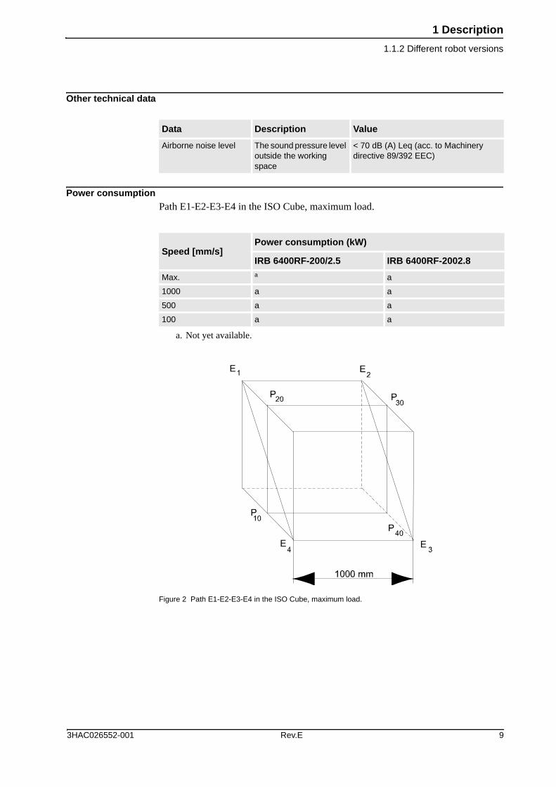
Other technical data
Power consumptionPath E1-E2-E3-E4 in the ISO Cube, maximum load.
Figure 2 Path E1-E2-E3-E4 in the ISO Cube, maximum load.
Data Description Value
Airborne noise level The sound pressure level outside the working space
< 70 dB (A) Leq (acc. to Machinery directive 89/392 EEC)
Speed [mm/s]Power consumption (kW)
IRB 6400RF-200/2.5 IRB 6400RF-2002.8
Max. a
a. Not yet available.
a
1000 a a
500 a a
100 a a
3HAC026552-001 Rev.E 9

1 Description1.1.2 Different robot versions
Dimensions IRB 6400RF
Figure 3 View of the manipulator from the side, rear and above (dimensions in mm).
Pos Description
A With wrist protection installed
B Fork lift device
10 Rev.E 3HAC026552-001

1 Description1.2.1 Standards
1.2 Safety/Standards
1.2.1 Standards
Health and safety standardsThe robot complies fully with the health and safety standards specified in the EEC’s Machinery Directives.The robot controlled by the IRC5 conforms to the following standards:
Standard Description
EN ISO 12100-1 Safety of machinery, terminology
EN ISO 12100-2 Safety of machinery, technical specifications
EN 954-1 Safety of machinery, safety related parts of control systems
EN ISO 60204-1:2005 Safety of machinery - Electrical equipment of machines
EN ISO 10218-1:2006a
a. There is a deviation from paragraph 6.2 in that only worst case stop distances andstop times are documented.
Robots for industrial environments - Safety requirements
EN 60204 Electrical equipment of industrial machines
EN 61000-6-4 (option) EMC, Generic emission
EN 61000-6-2 EMC, Generic immunity
Standard Description
IEC 60529 Degrees of protection provided by enclosures
Standard Description
ISO 9787 Manipulating industrial robots, coordinate systems and motions
Standard Description
ANSI/RIA 15.06/1999 Safety Requirements for Industrial Robots and Robot Systems
ANSI/UL 1740-1998 (option)
Safety Standard for Robots and Robotic Equipment
CAN/CSA Z 434-03 (option)
Industrial Robots and Robot Systems - General Safety Requirements
3HAC026552-001 Rev.E 11

1 Description1.2.1 Standards
SafetyThe robot controller is designed with absolute safety in mind. It has a dedicated safety system based on a two-channel circuit which is continuously monitored. If any component fails, the electrical power supplied to the motors is cut off and the brakes engage.
Safety function Description
Safety category 3 Malfunction of a single component, such as a sticking relay, will be detected at the next MOTOR OFF/MOTOR ON operation. MOTOR ON is then prevented and the faulty section is indicated. The executing circuits are continuously monitored.This complies with category 3 of EN 954-1, Safety of machinery - safety related parts of control systems - Part 1.
Selecting the operating mode
The robot can be operated either manually or automatically. In manual mode, the robot can only be operated via the FlexPendant, that is not by any external equipment.
Reduced speed In manual mode, the speed is limited to a maximum of 250 mm/s (600 inch/min.).The speed limitation applies not only to the TCP (Tool Center point), but to all parts of the robot. It is also possible to monitor the speed of equipment mounted on the robot.
Three position enabling device
The enabling device on the FlexPendant must be used to move the robot when in manual mode. The enabling device consists of a switch with three positions, meaning that all robot movements stop when either the enabling device is pushed fully in, or when it is released completely. This makes the robot safer to operate.An additional enabling device can be connected to the safety system, for two operator safety.
Safe manual movement
The robot is moved using a joystick instead of the operator having to look at the FlexPendant to find the right key.
Over-speed protection The speed of the robot is monitored by two independent computers.
Emergency stop There is one emergency stop push button on the controller and another one on the FlexPendant. Additional emergency stop buttons can be connected to the robot’s safety chain circuit.
Protective stop The controller has a number of electrical inputs which can be used to connect external safety equipment, such as safety gates and light curtains. This allows the robot’s safety functions to be activated both by peripheral equipment and by the robot itself.
Delayed protective stop A delayed stop gives a smooth stop. The robot stops in the same way as at a normal program stop with no deviation from the programmed path. After approximately 1 second the power supplied to the motors is cut off.
Collision detection In case of an unexpected mechanical disturbance like a collision, electrode sticking, etc., the robot will stop and then slightly back off from its stop position.
Restricting the working space
SoftwareThe movement of each axis can be restricted.HardwareLimit switches can be connected to the robot´s safety chain circuit.
12 Rev.E 3HAC026552-001

1 Description1.2.1 Standards
Hold-to-run control “Hold-to-run” means that you must depress the FlexPendant start button and another button in order to move the robot. When the hold-to-run button is released the robot will stop. The hold-to-run function makes program testing safer. At reduced speed it can be activated/deactivated by a system parameter.
Fire safety The control system complies with UL’s (Underwriters Laboratories Inc.) requirements for fire safety.
Safety lamp As an option, a safety lamp mounted on the manipulator can be connected. The lamp is activated when the controller is in the MOTORS ON state.
MultiMove When several robots are connected to one Control Module, all these robots are regarded as one robot from the safety system’s point of view. When in manual mode all coordinated robots can be jogged simultaneously as well as only one robot or other mechanical unit at a time can be jogged, selected from the FlexPendant.
Safety function Description
3HAC026552-001 Rev.E 13
1 Description1.3.1 Introduction
1.3 Installation
1.3.1 Introduction
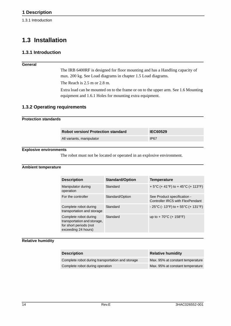
GeneralThe IRB 6400RF is designed for floor mounting and has a Handling capacity of max. 200 kg. See Load diagrams in chapter 1.5 Load diagrams.The Reach is 2.5 m or 2.8 m.Extra load can be mounted on to the frame or on to the upper arm. See 1.6 Mounting equipment and 1.6.1 Holes for mounting extra equipment.
1.3.2 Operating requirements
Protection standards
Explosive environmentsThe robot must not be located or operated in an explosive environment.
Ambient temperature
Relative humidity
Robot version/ Protection standard IEC60529
All variants, manipulator IP67
Description Standard/Option Temperature
Manipulator during operation
Standard + 5°C (+ 41°F) to + 45°C (+ 113°F)
For the controller Standard/Option See Product specification - Controller IRC5 with FlexPendant
Complete robot during transportation and storage
Standard - 25°C (- 13°F) to + 55°C (+ 131°F)
Complete robot during transportation and storage, for short periods (not exceeding 24 hours)
Standard up to + 70°C (+ 158°F)
Description Relative humidity
Complete robot during transportation and storage Max. 95% at constant temperature
Complete robot during operation Max. 95% at constant temperature
14 Rev.E 3HAC026552-001

1 Description1.3.3 Mounting the manipulator
1.3.3 Mounting the manipulator
Maximum load in relation to the base coordinate system.
Figure 4 Direction of forces.
Note regarding Mxy and Fxy
The bending torque (Mxy) can occur in any direction in the XY-plane of the base coordinate system.The same applies to the transverse force (Fxy).
Endurance load in operation Max. load at emergency stop
Force XY ± 1400 N ± 38000 N
Force Z 22000 ± 8000 N 22000 ± 19000 N
Torque XY ± 34000 Nm ± 61000 Nm
Torque Z ± 7000 Nm ± 15000 Nm
3HAC026552-001 Rev.E 15

1 Description1.3.3 Mounting the manipulator
Figure 5 Hole configuration for robot base (dimensions in mm).
16 Rev.E 3HAC026552-001

1 Description1.4.1 Fine calibration
1.4 Calibration and References
1.4.1 Fine calibration
GeneralFine calibration is made using the Levelmeter 2000, please see Product manual - Instruction for Levelmeter calibration.
1.4.2 Absolute Accuracy calibration
GeneralRequires RobotWare option Absolute Accuracy, please see Product specification - Controller software IRC5/RobotWare Options for more details.
The calibration conceptAbsolute Accuracy (AbsAcc) is a calibration concept, which ensures a TCP absolute accuracy of better than ± 1 mm in the entire working range.Absolute accuracy compensates for:
• Mechanical tolerances in the robot structure
• Deflection due to load
Absolute accuracy calibration is focusing on positioning accuracy in the cartesian coordinate system for the robot. It also includes load compensation for deflection caused by the tool and equipment. Tool data from robot program is used for this purpose. The positioning will be within specified performance regardless of load.
Calibration dataThe user is supplied with robot calibration data (compensation parameters saved on the manipulator SMB) and a certificate that shows the performance (Birth certifi-cate). The difference between an ideal robot and a real robot without AbsAcc can typically be 8 mm, resulting from mechanical tolerances and deflection in the robot structure.If there is a difference, at first start-up, between calibration data in controller and the robot SMB, correct by copying data from SMB to controller.
3HAC026552-001 Rev.E 17

1 Description1.4.2 Absolute Accuracy calibration
Absolute Accuracy optionAbsolute Accuracy option is integrated in the controller algorithms for compensation of this difference and does not need external equipment or calculation.Absolute Accuracy is a RobotWare option and includes an individual calibration of the robot (mechanical arm).Absolute Accuracy is a TCP calibration in order to Reach (m) a good positioning in the Cartesian coordinate system.
Figure 6 The Cartesian coordinate system.
Production dataTypical production data regarding calibration are:
RobotPositioning accuracy (mm)
Average Max % Within 1 mm
IRB 6400RF-200/2.5 0.55 mm 1.20 mm 95%
IRB 6400RF-200/2.8 0.55 mm 1.20 mm 95%
18 Rev.E 3HAC026552-001

1 Description1.5.1 Introduction
1.5 Load diagrams
1.5.1 Introduction
If incorrect load data and/or loads outside load diagram is used the following parts can be damaged due to overload:
• motors
• gearboxes
• mechanical structure
GeneralThe load diagrams include a nominal payload inertia of J0<100 kgm2.J0 is the maximum component (JX0=, JY0= and JZ0=) of the moment of inertia of the handling weight at is center of gravity.
Control of load case by “RobotLoad”For an easy check of a specific load case, use the calculation program ABB RobotLoad. Please contact your local ABB organization.
It is very important to always define correct actual load data and correct payload of the robot. Incorrect definitions of load data can result in overloading of the robot.
In the robot system is the service routine LoadIdentify available, which allows the user to make an automatic definition of the tool and load, to determine correct load parameters. Please see Operating Manual - IRC5 with FlexPendant, art. No. 3HAC16590-1, for detailed information.
Robots running with incorrect load data and/or with loads outside load diagram will not be covered by the robot warranty.
3HAC026552-001 Rev.E 19

1 Description1.5.2 Diagram
1.5.2 Diagram
IRB 6400RF-200/2.5 and IRB 6400RF-200/2.8
Figure 7 Maximum permitted load mounted on the robot tool flange at different positions (center of gravity).
20 Rev.E 3HAC026552-001

1 Description1.5.2 Diagram
1.6 Mounting equipment
GeneralExtra loads can be mounted on the upper arm and on the robot base. Definitions of distances and masses are shown in Figure 8. The robot is supplied with holes for mounting of extra equipment. See Figure 10. Maximum permitted load depends on center of gravity of arm load and robot payload.
Upper armFor permitted extra load on upper arm and the maximum handling capacity see Figure 8:
• M1 < 50 kg with distance a < 500 mm for center of gravity in axis 3 extension
or• M2 < 50 kg with distance b < 400 mm
or• M3 < 15 kg with distance c > 300 mm
When the handling weight is lower than the max. handling capacity (200 kg), M1 or M2 can be increased with the difference.For instance, with a handling weight of 150 kg the extra load for M1 or M2 can be 100 kg.
Figure 8 Permitted extra load on the upper arm.
Pos Description
A Mass center
3HAC026552-001 Rev.E 21

1 Description1.5.2 Diagram
Robot baseFor permitted extra load on the robot base, use the formula:
• JH = JH0 + M4 x R2
For recommended position of extra load, see Figure 9.
Figure 9 Permitted extra load for the robot base.
Quantity Description
JH = 120 kgm2 Permitted moment of inertia for the robot base
JH0 (kgm2) Moment of inertia for the extra load
R (m) Radius from center of axis 1
M4 (kg) Total mass of the extra load
Pos Description
A View from above
B View from the rear
22 Rev.E 3HAC026552-001

1 Description1.6.1 Holes for mounting extra equipment
1.6.1 Holes for mounting extra equipment
Upper arm
Figure 10 Holes for mounting of extra equipment on to the upper arm (dimensions in mm).
Pos Description
A From the rear
B 104 for “Hole 1”93 for “Hole 2”
C M10 (4x) Depth 20
D “Hole 1”
E “Hole 2”
3HAC026552-001 Rev.E 23

1 Description1.6.1 Holes for mounting extra equipment
Robot base
Figure 11 Holes for mounting of equipment on to the robot base (dimensions in mm).
Robot tool flange
Figure 12 The robot tool flange, ISO 9409-1-A125 (dimensions in mm).
Pos Description
A M10 (8x) on both sides, depth min. 20
B View from above
C Ø 18 (2x3) on both sides (use a 170 mm long bolt when mounting additional equipment)
Pos Description
A D = 10 H7 depth 10
B M10 (6x) depth 18
24 Rev.E 3HAC026552-001

1 Description1.7.1 Introduction
1.7 Robot Motion
1.7.1 Introduction
IRB 6400RF
Axis Type of motionRange of movement
from to
1 Rotation motion +180° -180°
2 Arm motion +85° -70°
3 Arm motion +110° -28°
4 Wrist motion +300° -300°
5 Bend motion +120° -120°
6 Turn motion +300° -300°+150 rev.a to -150 rev. Max.b
a. rev. = Revolutionsb. The default working range for axis 6 can be extended by changing parameter values in
the software.Option 610-1 “Independent axis” can be used for resetting the revolution counter afterthe axis has been rotated (no need for “rewinding” the axis).
3HAC026552-001 Rev.E 25

1 Description1.7.1 Introduction
Figure 13 The extreme positions of the robot arms.
Positions and angles IRB 6400RF-200/2.5
Pos No. (see Figure 13) X Position (mm) Z Position (mm)
0 1415 2075
1 185 1909
2 415 1445
3 766 387
4 1096 -290
5 2467 701
6 1804 2389
26 Rev.E 3HAC026552-001

1 Description1.7.1 Introduction
Positions and angles IRB 6400RF-200/2.8
Pos No. (see Figure 13) X Position (mm) Z Position (mm)
0 1760 2075
1 490 2071
2 760 1463
3 648 63
4 978 -614
5 2791 583
6 2108 2551
3HAC026552-001 Rev.E 27

1 Description1.7.2 Performance according to ISO 9283
1.7.2 Performance according to ISO 9283
GeneralAt rated maximum load, maximum offset and 1 m/s velocity on the inclined ISO test plane, 1 m cube with all axes in motion.The figures for AP, RP, AT and RT are mesured according to Figure 14.
Figure 14 Explanation of ISO values.
The above values are the range of average test results from a number of robots.
Pos Description Pos Description
A Programmed position E Programmed path
B Mean position at program execution D Actual path at program execution
AP Mean distance from programmed position
AT Max deviation from E
RP Tolerance of posiotion B at repeated positioning
RT Tolerance of the path at repeated program execution
Description IRB 6400RF-200/2.5 and -200/2.8
Pose accuracy, APa (mm)
a. AP according to the ISO test above, is the difference between the teached position(position manually modified in the cell) and the average position obtained duringprogram execution.
Not yet available
Pose repeatability, RP (mm) 0.1
Pose stabilization time, Pst (s) 0.35
Path accuracy, AT (mm) 2.1
Path repeatability, RT (mm) 1.0
28 Rev.E 3HAC026552-001
1 Description1.7.3 Velocity
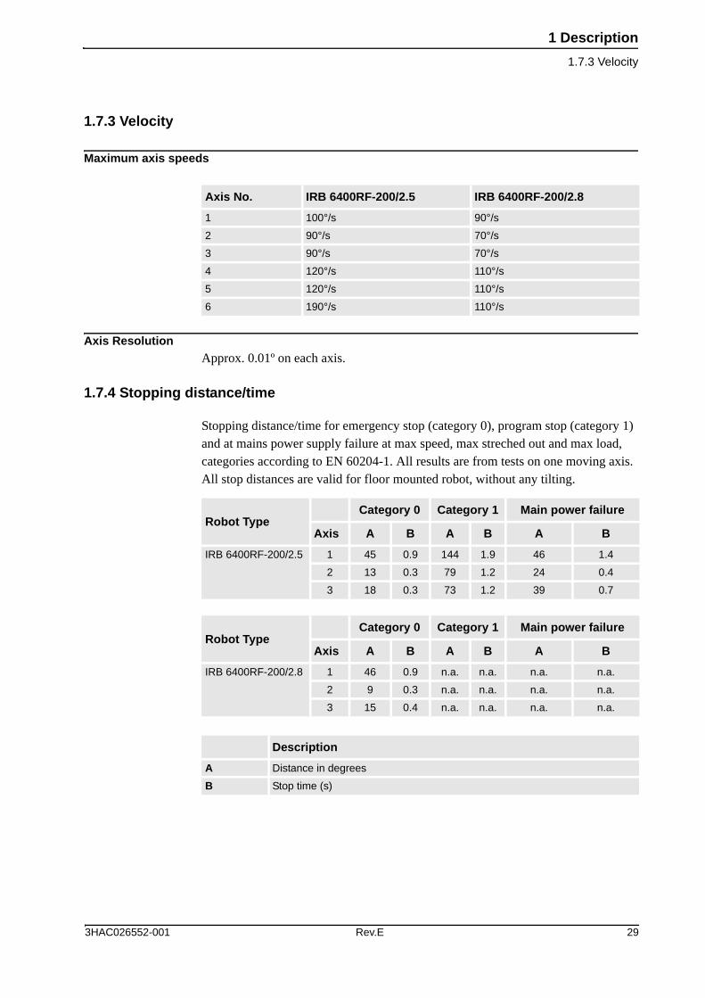
1.7.3 Velocity
Maximum axis speeds
Axis ResolutionApprox. 0.01º on each axis.
1.7.4 Stopping distance/time
Stopping distance/time for emergency stop (category 0), program stop (category 1) and at mains power supply failure at max speed, max streched out and max load, categories according to EN 60204-1. All results are from tests on one moving axis. All stop distances are valid for floor mounted robot, without any tilting.
Axis No. IRB 6400RF-200/2.5 IRB 6400RF-200/2.8
1 100°/s 90°/s
2 90°/s 70°/s
3 90°/s 70°/s
4 120°/s 110°/s
5 120°/s 110°/s
6 190°/s 110°/s
Robot TypeCategory 0 Category 1 Main power failure
Axis A B A B A B
IRB 6400RF-200/2.5 1 45 0.9 144 1.9 46 1.4
2 13 0.3 79 1.2 24 0.4
3 18 0.3 73 1.2 39 0.7
Robot TypeCategory 0 Category 1 Main power failure
Axis A B A B A B
IRB 6400RF-200/2.8 1 46 0.9 n.a. n.a. n.a. n.a.
2 9 0.3 n.a. n.a. n.a. n.a.
3 15 0.4 n.a. n.a. n.a. n.a.
Description
A Distance in degrees
B Stop time (s)
3HAC026552-001 Rev.E 29

1 Description1.8.1 Introduction
1.8 Customer connections
1.8.1 Introduction
GeneralCustomer connection in terms of Customer Power (CP), Customer Signals (CS) and Air are integrated in the robot and starts on the robot base and ends on the upper arm at axis 4.For the specification of the customer connection, see Specification of Variants and Options, Media outlet.
1.9 Maintenance and Troubleshooting
1.9.1 Introduction
GeneralThe robot requires only a minimum maintenance during operation. It is designed to make it as easy to service as possible:
• Maintenance-free AC motors are used.
• Liquid grease and oil is used for the gear boxes.
• The cabling is routed for longevity, and in the unlikely event of a failure, its modular design makes it easy to change.
MaintenanceThe maintenance intervals depend on the use of the robot, the required maintenance activities also depends on selected options. For detailed information on maintenance procedures, see Maintenance section in the Product Manual.
30 Rev.E 3HAC026552-001

2 Specification of Variants and Options2.1.1 General
2 Specification of Variants and Options
2.1 Introduction
2.1.1 General
The different variants and options for the IRB 6400RF are described below.The same numbers are used here as in the Specification form.For controller options, see Product specification - Controller IRC5 with FlexPendant, and for software options, see Product specification - Controller software IRC5/RobotWare Options.
2.1.2 Manipulator
Variants
Manipulator color
Safety lamp
Fork lift device
Option Robot type Handling capacity (kg) Reach (m)
435-15 IRB 6400RF-200/2.5 200 kg 2.5 m
435-23 IRB 6400RF-200/2.8 200 kg 2.8 m
Option Name Description
209-1 ABB Orangestandard
The robot is painted in color ABB Orange.
209-4--192 RAL code The manipulator is painted with chosen RAL-color
Option Name Description
213-1 Safety lamp A safety lamp with an orange fixed light can be mounted on the manipulator.The safety lamp is active in MOTORS ON mode. The safety lamp is required on a UL/UR approved robot.
Option Name Description
159-1 Fork lift device Lifting device on the manipulator for fork-lifthandling is mounted at delivery.Lifting eyes for use with an overhead crane is integrated as standard.
3HAC026552-001 Rev.E 31

2 Specification of Variants and Options2.1.2 Manipulator
Brake release cover
The brake release cover (option 50-1) is always included in the IRB 6400RF.
Position switches axis 1
Position switches connected to
Working range limitTo increase the safety of the robot, the working range of axis 1, 2 and 3 can be restricted by extra mechanical stops.
Option Name Description
50-1 Brake release cover Protective cover overpush-buttons on brake release unit.
Option Name Description
25-3 Three Three redundant position zones are available, each with two independent switches and cams. Two plus one zone.
Option Name Description
271-1 Cabinet Connection on the cabinet wall.Cables inside the cabinet are included.
Option Name Description
29-1 Axis 1, 15 degrees Two stops which allow the working range to be restricted in increments of 15°.
29-2 Axis 1, 7.5 degrees Two stops, which allow the working range to be restricted in increments of 7.5°.
32-1 Axis 2 Six stops which allow the working range to be restricted in increments of 15º at both end positions. Each stop decreases the motion by 15°.
34-1 Axis 3 Six stops which allow the working range to be restricted in increments of 15º at both end positions. Each stop decreases the motion by 15°.
32 Rev.E 3HAC026552-001

2 Specification of Variants and Options2.1.3 Floor cables
2.1.3 Floor cables
GeneralAdditional floor cable options for Process DressPack, see chapter 2.1.5 DressPack Floor.
Manipulator cable length
Cable length, Position switches axis 1
Option Lengths
210-2 7 m
210-3 15 m
210-4 22 m
210-5 30 m
Option Lengths
273-1 7 m
273-2 15 m
273-3 22 m
273-4 30 m
3HAC026552-001 Rev.E 33

2 Specification of Variants and Options2.1.4 Process DressPack
2.1.4 Process DressPack
Media outlet
Figure 15 Customer connections at the upper arm axis 4.
Option Name
218-6 At upper arm axis 4
TypeAt terminals in cabinet
At connection point
Cable part area
Allowed capacity
Customer Power (CP)Utility PowerProtective earth
2 21
1.0 mm2
1.0 mm2250V AC, 8 A250V AC, 8 A
Customer Signals (CS) 10 10 0.24 mm2 50V AC/DC 250 mA
Customer busCAN/DeviceNet PowerCAN/DeviceNet Signals separate shielded
22+1
22+1
0.24 mm2
0.24 mm250V AC/DC, 2 A5V AC/DC, 250 mA
MediaAir (PROC 1) 1 13 mm inner
diameterMax. 10 bar
Pos Connection type Description
A R2.CP Customer power
B R2.CS Customer signal
C R2.CANBUS CAN/DeviceNet signal
D R2.CAIR Customer air
34 Rev.E 3HAC026552-001

2 Specification of Variants and Options2.1.4 Process DressPack
Connected to
Figure 16 Connections at the robot base.
Option Name Description
16-1 Cabineta
a. Note! In a MultiMove application additional robots have no Control module. Thescrew terminals with internal cabling are then delivered separately to be mountedin the main robot Control module or in another encapsulation.
The signals are connected to 12-pole screw terminals, Phoenix MSTB 2.5/12-ST-5.08 to the Control module.
Pos Connection type Description
A R1.MP Motor power
B R1.SMB Serial measurement board signal
C R1.CP/CS Customer power and Customer signal
D R1.CAIR Customer air
E R1.SW1 Position switches axis 1
(A)
(B)
(C)
(D)
(E)
3HAC026552-001 Rev.E 35
2 Specification of Variants and Options2.1.4 Process DressPack
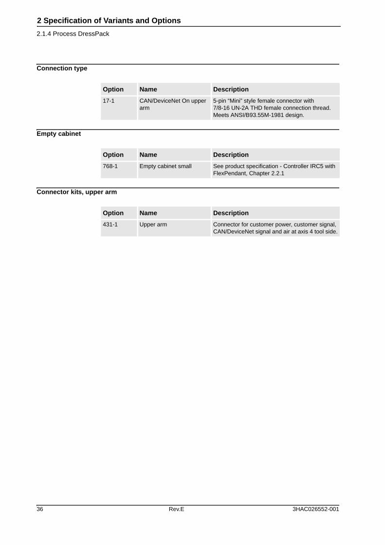
Connection type
Empty cabinet
Connector kits, upper arm
Option Name Description
17-1 CAN/DeviceNet On upper arm
5-pin “Mini” style female connector with 7/8-16 UN-2A THD female connection thread. Meets ANSI/B93.55M-1981 design.
Option Name Description
768-1 Empty cabinet small See product specification - Controller IRC5 with FlexPendant, Chapter 2.2.1
Option Name Description
431-1 Upper arm Connector for customer power, customer signal, CAN/DeviceNet signal and air at axis 4 tool side.
36 Rev.E 3HAC026552-001

2 Specification of Variants and Options2.1.5 DressPack Floor
2.1.5 DressPack Floor
Connection of Media outlet and CAN/DeviceNet
Connection to First drive
Connection to First and Second drive
2.1.6 Documentation
DVD User Documentation
Option Lengths
90-2 7 m
90-3 15 m
90-4 22 m
90-5 30 m
Option Lengths
786-1 7 m
786-2 15 m
786-3 22 m
786-4 30 m
Option Lengths
787-1 7 m
787-2 15 m
787-3 22 m
787-4 30 m
Option Type Description
808-1 Documentation on DVD See Product specification Robot User Documentation
3HAC026552-001 Rev.E 37

2 Specification of Variants and Options2.1.6 Documentation
38 Rev.E 3HAC026552-001

3 Accessories
3 AccessoriesThere is a range of tools and equipment available, specially designed for the robot.
Basic software and software options for robot and PCFor more information, see Product specification - Controller IRC5 with FlexPendant and Product specification - Controller software IRC5/RobotWare Options.
Robot Peripherals• Track Motion
• Motor Units
3HAC026552-001 Rev.E 39

3 Accessories
40 Rev.E 3HAC026552-001

Index
AAccessories, 39accessories, 39Additional functionality, 7Advanced shape Tuning, 7Ambient temprature, 14application programs, 7Application support, 7available, 39axis 1, 32
Bbase coordinate system, 15Basic software, 39Brake release cover, 32
CCabinet, 35CAN/DeviceNet, 37Collision Detection, 7Communication, 7Connection, 36, 37Connector kits, 36Conveyor Tracking, 7cooling device, 9DDevelopment, 7DressPack Floor, 37
Eequipment
mounting, 21permitted extra load, 21
Equipment, available, 39Execution, 7Explosive environments, 14
FFloor cables, 33Fork lift device, 10, 31forklift, 29FoundryPlus protection, 7HHandling capacity, 7, 31Hole configuration, 16
IIRC5 controller, 7ISO Cube, 9Llength, 33load diagrams, 19
MMachine Tending, 7
Manipulator axes, 8Manipulator cable, 33Manipulator color, 31Material Handling, 7Maximum load, 15Media outlet, 34, 37Motion control, 7Motion coordination, 7Motion performance, 7Motor Units, 39mounting
extra equipment, 21MultiMove Coordinated, 7NNoise level, 9OOptions, 31options, 31
PPosition switch, 32position switch, 32Power consumption, 9Pre-Machining applications, 7Process DressPack, 34Protection standards, 14
RReach, 7, 31Relative humidity, 14Robot Peripherals, 39Robot versions, 8RobotWare, 7SSafety, 11Safety lamp, 31Sensor Synchronization, 7service position indicator, 32Software option, 39Space requirements, 9Standard, 11standard, RAL code, 31structure, 7TTools, 39Track Motion, 39type, 36
Uupper arm, 36
VVariants, 31
3HAC026552-001 Rev.E 41

Index
WWorking range limit, 32wrist protection, 10
42 Rev.E 3HAC026552-001


ABB ABRobotics ProductsS-721 68 VÄSTERÅSSWEDENTelephone: +46 (0) 21 344000Telefax: +46 (0) 21 132592
3HA
C 0
2655
2-00
1, R
evis
ion
E, e
n