Embed Size (px)
Citation preview
3GPP TS 36.213 V8.2.0 (2008-03)Technical Specification
3rd Generation Partnership Project;Technical Specification Group Radio Access Network;Evolved Universal Terrestrial Radio Access (E-UTRA);
Physical layer procedures(Release 8)
The present document has been developed within the 3rd Generation Partnership Project (3GPP TM) and may be further elaborated for the purposes of 3GPP. The present document has not been subject to any approval process by the 3GPP Organisational Partners and shall not be implemented. This Specification is provided for future development work within 3GPP only. The Organisational Partners accept no liability for any use of this Specification.Specifications and reports for implementation of the 3GPP TM system should be obtained via the 3GPP Organisational Partners’ Publications Offices.
HTC/ZTE EXHIBIT 1004
3GPP
3GPP TS 36.213 V8.2.0 (2008-03)2Release 8
Keywords UMTS, radio, layer 1
3GPP
Postal address
3GPP support office address 650 Route des Lucioles – Sophia Antipolis
Valbonne – France Tel.: +33 4 92 94 42 00 Fax: +33 4 93 65 47 16
Internet http://www.3gpp.org
Copyright Notification
No part may be reproduced except as authorized by written permission. The copyright and the foregoing restriction extend to reproduction in all media.
© 2008, 3GPP Organizational Partners (ARIB, ATIS, CCSA, ETSI, TTA, TTC).
All rights reserved.
HTC/ZTE EXHIBIT 1004-2
3GPP
3GPP TS 36.213 V8.2.0 (2008-03)3Release 8
Contents Foreword ............................................................................................................................................................5 1 Scope ........................................................................................................................................................6 2 References ................................................................................................................................................6 3 Definitions, symbols, and abbreviations ..................................................................................................6 3.1 Symbols ............................................................................................................................................................. 6 3.2 Abbreviations..................................................................................................................................................... 6 4 Synchronisation procedures .....................................................................................................................7 4.1 Cell search ......................................................................................................................................................... 7 4.2 Timing synchronisation ..................................................................................................................................... 7 4.2.1 Synchronisation primitives........................................................................................................................... 7 4.2.2 Radio link monitoring .................................................................................................................................. 7 4.2.3 Inter-cell synchronisation............................................................................................................................. 7 4.2.4 Transmission timing adjustments................................................................................................................. 7 5 Power control ...........................................................................................................................................8 5.1 Uplink power control ......................................................................................................................................... 8 5.1.1 Physical uplink shared channel .................................................................................................................... 8 5.1.1.1 UE behaviour.......................................................................................................................................... 8 5.1.2 Physical uplink control channel ................................................................................................................... 9 5.1.2.1 UE behaviour.......................................................................................................................................... 9 5.1.3 Sounding Reference Symbol ...................................................................................................................... 10 5.1.3.1 UE behaviour........................................................................................................................................ 10 5.2 Downlink power allocation.............................................................................................................................. 11 5.2.1 UE behaviour ............................................................................................................................................. 11 5.2.2 eNodeB behaviour...................................................................................................................................... 11 5.2.3 Downlink channel subcarrier transmit power offset................................................................................... 11 6 Random access procedure ......................................................................................................................11 6.1 Physical non-synchronized random access procedure ..................................................................................... 12 6.1.1 Timing........................................................................................................................................................ 12 6.1.1.1 Synchronized ........................................................................................................................................ 12 6.1.1.2 Unsynchronized.................................................................................................................................... 12 6.1.2 Preamble Sequence selection ..................................................................................................................... 12 7 Physical downlink shared channel related procedures ...........................................................................12 7.1 UE procedure for receiving the physical downlink shared channel................................................................. 12 7.1.1 Single-antenna port .................................................................................................................................... 12 7.1.2 Transmit diversity..................................................................................................................................... 13 7.1.3 Open-loop spatial multiplexing ................................................................................................................ 13 7.1.4 Closed-loop spatial multiplexing.............................................................................................................. 13 7.1.5 Void .......................................................................................................................................................... 13 7.1.6 Resource allocation................................................................................................................................... 13 7.1.6.1 Resource allocation type 0.................................................................................................................... 13 7.1.6.2 Resource allocation type 1.................................................................................................................... 14 7.1.6.3 Resource allocation type 2.................................................................................................................... 14 7.2 UE procedure for reporting channel quality indication (CQI), precoding matrix indicator (PMI) and rank
indication (RI).................................................................................................................................................. 15 7.2.1 Aperiodic/Periodic CQI/PMI/RI Reporting using PUSCH ........................................................................ 16 7.2.2 Periodic CQI/PMI/RI Reporting using PUCCH......................................................................................... 20 7.2.3 Channel quality indicator (CQI) definition ................................................................................................ 23 7.2.4 Precoding Matrix Indicator (PMI) definition ............................................................................................. 25 8 Physical uplink shared channel related procedures ................................................................................25 8.1 Resource Allocation for PDCCH DCI Format 0.............................................................................................. 25 8.2 UE sounding procedure ................................................................................................................................... 25 8.2.1 Sounding definition.................................................................................................................................... 26
HTC/ZTE EXHIBIT 1004-3
3GPP
3GPP TS 36.213 V8.2.0 (2008-03)4Release 8
8.3 UE ACK/NACK procedure ............................................................................................................................. 26 8.4 UE PUSCH Hopping procedure ...................................................................................................................... 26 8.4.1 Type 1 PUSCH Hopping............................................................................................................................ 27 8.4.2 Type 2 PUSCH Hopping............................................................................................................................ 27 8.5 UE Reference Symbol procedure..................................................................................................................... 28 9 Physical downlink control channel procedures ......................................................................................28 9.1 UE procedure for determining physical downlink control channel assignment............................................... 28 9.1.1 PDCCH Assignment Procedure ................................................................................................................. 28 9.1.2 PHICH Assignment Procedure................................................................................................................... 28 10 Physical uplink control channel procedures...........................................................................................29 10.1 UE procedure for determining physical uplink control channel assignment ................................................... 29 10.2 Uplink ACK/NACK timing ............................................................................................................................. 29
Annex A (informative): Change history ...............................................................................................30
HTC/ZTE EXHIBIT 1004-4
3GPP
3GPP TS 36.213 V8.2.0 (2008-03)5Release 8
Foreword This Technical Specification (TS) has been produced by the 3rd Generation Partnership Project (3GPP).
The contents of the present document are subject to continuing work within the TSG and may change following formal TSG approval. Should the TSG modify the contents of this present document, it will be re-released by the TSG with an identifying change of release date and an increase in version number as follows:
Version x.y.z
where:
x the first digit:
1 presented to TSG for information;
2 presented to TSG for approval;
3 or greater indicates TSG approved document under change control.
y the second digit is incremented for all changes of substance, i.e. technical enhancements, corrections, updates, etc.
z the third digit is incremented when editorial only changes have been incorporated in the document.
HTC/ZTE EXHIBIT 1004-5
3GPP
3GPP TS 36.213 V8.2.0 (2008-03)6Release 8
1 Scope The present document specifies and establishes the characteristics of the physicals layer procedures in the FDD and TDD modes of E-UTRA.
2 References The following documents contain provisions which, through reference in this text, constitute provisions of the present document.
• References are either specific (identified by date of publication, edition number, version number, etc.) or non-specific.
• For a specific reference, subsequent revisions do not apply.
• For a non-specific reference, the latest version applies. In the case of a reference to a 3GPP document (including a GSM document), a non-specific reference implicitly refers to the latest version of that document in the same Release as the present document.
[1] 3GPP TR 21.905: “Vocabulary for 3GPP Specifications”
[2] 3GPP TS 36.201: “Evolved Universal Terrestrial Radio Access (E-UTRA); Physical Layer – General Description”
[3] 3GPP TS 36.211: “Evolved Universal Terrestrial Radio Access (E-UTRA); Physical channels and modulation”
[4] 3GPP TS 36.212: “Evolved Universal Terrestrial Radio Access (E-UTRA); Multiplexing and channel coding”
[5] 3GPP TS 36.214: “Evolved Universal Terrestrial Radio Access (E-UTRA); Physical layer – Measurements”
3 Definitions, symbols, and abbreviations
3.1 Symbols For the purposes of the present document, the following symbols apply:
DLRBN Downlink bandwidth configuration, expressed in units of RB
scN as defined in [3] ULRBN Uplink bandwidth configuration, expressed in units of RB
scN as defined in [3]
sT Basic time unit as defined in [3]
3.2 Abbreviations For the purposes of the present document, the following abbreviations apply.
ACK Acknowledgement BCH Broadcast Channel CCE Control Channel Element CQI Channel Quality Indicator CRC Cyclic Redundancy Check
HTC/ZTE EXHIBIT 1004-6
3GPP
3GPP TS 36.213 V8.2.0 (2008-03)7Release 8
DL Downlink DTX Discontinuous Transmission EPRE Energy Per Resource Element MCS Modulation and Coding Scheme NACK Negative Acknowledgement PBCH Physical Broadcast Channel PCFICH Physical Control Format Indicator Channel PDCCH Physical Downlink Control Channel PDSCH Physical Downlink Shared Channel PHICH Physical Hybrid ARQ Indicator Channel PRACH Physical Random Access Channel PRB Physical Resource Block PUCCH Physical Uplink Control Channel PUSCH Physical Uplink Shared Channel QoS Quality of Service RBG Resource Block Group RE Resource Element RPF Repetition Factor RS Reference Signal SIR Signal-to-Interference Ratio SINR Signal to Interference plus Noise Ratio SRS Sounding Reference Symbol TA Time alignment TTI Transmission Time Interval UE User Equipment UL Uplink UL-SCH Uplink Shared Channel VRB Virtual Resource Block
4 Synchronisation procedures
4.1 Cell search Cell search is the procedure by which a UE acquires time and frequency synchronization with a cell and detects the physical layer Cell ID of that cell. E-UTRA cell search supports a scalable overall transmission bandwidth corresponding to 6 resource blocks and upwards.
The following signals are transmitted in the downlink to facilitate cell search: the primary and secondary synchronization signals.
4.2 Timing synchronisation
4.2.1 Synchronisation primitives
4.2.2 Radio link monitoring
4.2.3 Inter-cell synchronisation [For example, for cell sites with a multicast physical channel]
4.2.4 Transmission timing adjustments Upon reception of a timing advance command, the UE shall adjust its uplink transmission timing. The timing advance command is expressed in multiples of 16 sT and is relative to the current uplink timing.
HTC/ZTE EXHIBIT 1004-7
3GPP
3GPP TS 36.213 V8.2.0 (2008-03)8Release 8
For a timing advance command received on subframe n, then corresponding adjustment occurs at the beginning of subframe n+x.
Editor’s note: RAN1 needs to agree on x.
5 Power control Downlink power control determines the energy per resource element (EPRE). The term resource element energy denotes the energy prior to CP insertion. The term resource element energy also denotes the average energy taken over all constellation points for the modulation scheme applied. Uplink power control determines the average power over a DFT-SOFDM symbol in which the physical channel is transmitted.
5.1 Uplink power control Uplink power control controls the transmit power of the different uplink physical channels.
A cell wide overload indicator (OI) is exchanged over X2 for inter-cell power control. An indication X also exchanged over X2 indicates PRBs that an eNodeB scheduler allocates to cell edge UEs and that will be most sensitive to inter-cell interference.
[Note: Above lines regarding OI, X and X2 to be moved to an appropriate RAN3 spec when it becomes available]
5.1.1 Physical uplink shared channel
5.1.1.1 UE behaviour
The setting of the UE Transmit power PUSCHP for the physical uplink shared channel (PUSCH) transmission in subframe i is defined by
)}())(()())((log10,min{)( TFO_PUSCHPUSCH10MAXPUSCH ifiTFPLjPiMPiP +Δ+⋅++= α [dBm]
where,
• MAXP is the maximum allowed power that depends on the UE power class
• )(PUSCH iM is the size of the PUSCH resource assignment expressed in number of resource blocks valid for subframe i.
• )(O_PUSCH jP is a parameter composed of the sum of a 8-bit cell specific nominal component )( PUSCHO_NOMINAL_ jP signalled from higher layers for j=0 and 1 in the range of [-126,24] dBm with 1dB
resolution and a 4-bit UE specific component )(O_UE_PUSCH jP configured by RRC for j=0 and 1 in the range of [-8, 7] dB with 1dB resolution. For PUSCH (re)transmissions corresponding to a configured scheduling grant then j=0 and for PUSCH (re)transmissions corresponding to a received PDCCH with DCI format 0 associated with a new packet transmission then j=1.
• { }1,9.0,8.0,7.0,6.0,5.0,4.0,0∈α is a 3-bit cell specific parameter provided by higher layers
• PL is the downlink pathloss estimate calculated in the UE
• )12(log10))(( 10TF −=Δ ⋅ SKMPRiTF for 25.1=SK and 0 for 0=SK where SK is a cell specific parameter given by RRC
o )(iTF is the PUSCH transport format valid for subframe i
o MPR = modulation x coding rate = REINFO / NN where INFON are the number of information bits and
REN is the number of resource elements determined from )(iTF and )(PUSCH iM for subframe i
HTC/ZTE EXHIBIT 1004-8
3GPP
3GPP TS 36.213 V8.2.0 (2008-03)9Release 8
• PUSCHδ is a UE specific correction value, also referred to as a TPC command and is included in PDCCH with DCI format 0 or jointly coded with other TPC commands in PDCCH with DCI format 3/3A. The current PUSCH power control adjustment state is given by )(if which is defined by:
o )()1()( PUSCHPUSCH Kiifif −+−= δ if )(∗f represents accumulation
where 0)0( =f and PUSCHK = 4
The UE attempts to decode a PDCCH of DCI format 0 and a PDCCH of DCI format 3/3A in every subframe except when in DRX
0PUSCH =δ dB for a subframe where no TPC command is decoded or where DRX occurs.
The PUSCHδ dB accumulated values signalled on PDCCH with DCI format 0 are [-1, 0, 1, 3].
The PUSCHδ dB accumulated values signalled on PDCCH with DCI format 3/3A are one of [-1, 1] or [-1, 0, 1, 3] as semi-statically configured by higher layers.
If UE has reached maximum power, positive TPC commands are not accumulated
If UE has reached minimum power, negative TPC commands shall not be accumulated
UE shall reset accumulation
• at cell-change
• when entering/leaving RRC active state
• when an absolute TPC command is received
• when )(O_UE_PUSCH jP is received
• when the UE (re)synchronizes
o )()( PUSCHPUSCH Kiif −= δ if )(∗f represents current absolute value
where )(PUSCH PUSCHKi −δ was signalled on PDCCH with DCI format 0 on subframe
PUSCHKi −
where 4=PUSCHK
The PUSCHδ dB absolute values signalled on PDCCH with DCI format 0 are [-4,-1, 1, 4].
)1()( −= ifif for a subframe where no PDCCH with DCI format 0 is decoded or where DRX occurs.
o )(∗f type (accumulation or current absolute) is a UE specific parameter that is given by RRC.
5.1.2 Physical uplink control channel
5.1.2.1 UE behaviour
The setting of the UE Transmit power PUCCHP for the physical uplink control channel (PUCCH) transmission in subframe i is defined by
)}()(,min{)( TF_PUCCHO_PUCCHMAXPUCCH igTFPLPPiP +Δ++= [dBm]
where
• )(TF_PUCCH TFΔ table entries for each PUCCH transport format (TF ) defined in Table 5.4-1 in [3] are given by RRC
o Each signalled )(TF_PUCCH TFΔ 2-bit value corresponds to a TF relative to PUCCH DCI format 0.
HTC/ZTE EXHIBIT 1004-9
3GPP
3GPP TS 36.213 V8.2.0 (2008-03)10Release 8
• O_PUCCHP is a parameter composed of the sum of a 5-bit cell specific parameter PUCCH O_NOMINAL_P provided by higher layers with 1 dB resolution in the range of [-127, -96] dBm and a UE specific component
O_UE_PUCCHP configured by RRC in the range of [-8, 7] dB with 1 dB resolution.
• PUCCHδ is a UE specific correction value, also referred to as a TPC command, included in a PDCCH with DCI format 1A/1/2 or sent jointly coded with other UE specific PUCCH correction values on a PDCCH with DCI format 3/3A.
o The UE attempts to decode a PDCCH with DCI format 3/3A and a PDCCH with DCI format 1A/1/2 on every subframe except when in DRX.
o PUCCHδ from a PDCCH with DCI format 1A/1/2 overrides that from a PDCCH with DCI format 3/3A when both are decoded in a given subframe.
o PUCCHδ =0 dB for a subframe where no PDCCH with DCI format 1A/1/2/3/3A is decoded or where DRX occurs.
o )()1()( PUCCHPUCCH Kiigig −Δ+−= where )(ig is the current PUCCH power control adjustment state with initial condition 0)0( =g .
The PUCCHδ dB values signalled on PDCCH with DCI format 1A/1/2 are [-1, 0, 1, 3].
The PUCCHδ dB values signalled on PDCCH with DCI format 3/3A are [-1,1] or [-1,0,1,3] as semi-statically configured by higher layers.
If UE has reached maximum power, positive TPC commands are not accumulated
If UE has reached minimum power, negative TPC commands shall not be accumulated
UE shall reset accumulation
• at cell-change
• when entering/leaving RRC active state
• when )(O_UE_PUCCH jP is received
• when the UE (re)synchronizes
5.1.3 Sounding Reference Symbol
5.1.3.1 UE behaviour
The setting of the UE Transmit power SRSP for the Sounding Reference Symbol transmitted on subframe i is defined by
)}()()(log10,min{)( O_PUSCHSRS10SRS_OFFSETMAXSRS ifPLjPMPPiP +⋅+++= α [dBm]
where
• SRS_OFFSETP is a 4-bit UE specific parameter semi-statically configured by higher layers with 1dB step size in the range [-3, 12] dB.
• SRSM is the bandwidth of the SRS transmission in subframe i expressed in number of resource blocks.
• )(if is the current power control adjustment state for the PUSCH, see Section 5.1.1.1.
• )(O_PUSCH jP is a parameter as defined in Section 5.1.1.1.
HTC/ZTE EXHIBIT 1004-10
3GPP
3GPP TS 36.213 V8.2.0 (2008-03)11Release 8
5.2 Downlink power allocation The eNodeB determines the downlink transmit energy per resource element.
A UE may assume downlink reference symbol EPRE is constant across the downlink system bandwidth and constant across all subframes until different RS power information is received.
For each UE, the PDSCH-to-RS EPRE ratio among REs in all the OFDM symbols containing RS is equal and is denoted by Aρ .
The UE may assume that for 64 QAM or RI>1 spatial multiplexing Aρ is equal to AP which is a UE specific semi-static parameter signalled by higher layers.
For each UE, the PDSCH-to-RS EPRE ratio among REs in all the OFDM symbols not containing RS is equal and is denoted by Bρ .
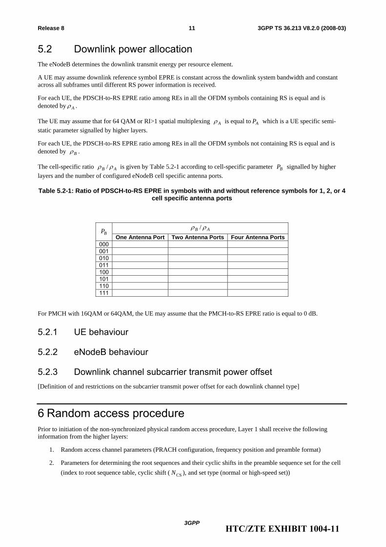
The cell-specific ratio AB ρρ / is given by Table 5.2-1 according to cell-specific parameter BP signalled by higher layers and the number of configured eNodeB cell specific antenna ports.
Table 5.2-1: Ratio of PDSCH-to-RS EPRE in symbols with and without reference symbols for 1, 2, or 4 cell specific antenna ports
AB ρρ / BP
One Antenna Port Two Antenna Ports Four Antenna Ports 000 001 010 011 100 101 110 111
For PMCH with 16QAM or 64QAM, the UE may assume that the PMCH-to-RS EPRE ratio is equal to 0 dB.
5.2.1 UE behaviour
5.2.2 eNodeB behaviour
5.2.3 Downlink channel subcarrier transmit power offset [Definition of and restrictions on the subcarrier transmit power offset for each downlink channel type]
6 Random access procedure Prior to initiation of the non-synchronized physical random access procedure, Layer 1 shall receive the following information from the higher layers:
1. Random access channel parameters (PRACH configuration, frequency position and preamble format)
2. Parameters for determining the root sequences and their cyclic shifts in the preamble sequence set for the cell (index to root sequence table, cyclic shift ( CSN ), and set type (normal or high-speed set))
HTC/ZTE EXHIBIT 1004-11
3GPP
3GPP TS 36.213 V8.2.0 (2008-03)12Release 8
6.1 Physical non-synchronized random access procedure From the physical layer perspective, the L1 random access procedure encompasses the transmission of random access preamble and random access response. The remaining messages are scheduled for transmission by the higher layer on the shared data channel and are not considered part of the L1 random access procedure. A random access channel occupies 6 resource blocks in a subframe or set of consecutive subframes reserved for random access preamble transmissions. The eNodeB is not prohibited from scheduling data in the resource blocks reserved for random access channel preamble transmission.
The following steps are required for the L1 random access procedure:
1. Layer 1 procedure is triggered upon request of a preamble transmission by higher layers.
2. A preamble index, preamble transmission power (PREAMBLE_TRANSMISSION_POWER), associated RA-RNTI, and PRACH resource are indicated by higher layers as part of the request.
3. A preamble sequence is then selected from the preamble sequence set using the preamble index.
4. A single preamble transmission then occurs using the selected preamble sequence with transmission power PREAMBLE_TRANSMISSION_POWER on the indicated PRACH resource.
5. If no associated PDCCH with RA-RNTI is detected within the random access response window then the corresponding DL-SCH transport block is passed to higher layers.
6. If the random access response window has past then the physical random access procedure is exited.
6.1.1 Timing
6.1.1.1 Synchronized
6.1.1.2 Unsynchronized
6.1.2 Preamble Sequence selection
7 Physical downlink shared channel related procedures
7.1 UE procedure for receiving the physical downlink shared channel
The UE is semi-statically configured via higher layer signalling to receive the physical downlink shared channel based on one of the following transmission modes:
1. Single-antenna port 2. Transmit diversity 3. Open-loop spatial multiplexing 4. Closed-loop spatial multiplexing 5. Multi-user MIMO
7.1.1 Single-antenna port In the single-antenna port mode, the UE may assume that the eNB transmits on the physical downlink shared channel according to Section 6.3.4.1 of [3]
HTC/ZTE EXHIBIT 1004-12
3GPP
3GPP TS 36.213 V8.2.0 (2008-03)13Release 8
7.1.2 Transmit diversity In the transmit diversity mode, the UE may assume that the eNB transmits on the physical downlink shared channel according to Section 6.3.4.3 of [3]
7.1.3 Open-loop spatial multiplexing In the open-loop spatial multiplexing transmission mode, the UE may assume, based on the rank indication (RI) obtained from the associated DCI as determined from the number of assigned transmission layers, that the eNB transmits on the physical downlink shared channel according to the following:
RI = 1 : transmit diversity as defined in Section 6.3.4.3 of [3] RI > 1 : large delay CDD as defined in Section 6.3.4.2.2 of [3]
For RI>1, the operation of large delay CDD is further defined as follows:
For 2 antenna ports, the precoder for data resource element index i, denoted by W(i) is selected according to 1)( CiW = where 1C denotes the precoding matrix corresponding to precoder index 1 in Table 6.3.4.2.3-1 of
[3]. For 4 anetnna ports, the UE may assume that the eNB cyclically assigns different precoders to different data
resource elements on the physical downlink shared channel as follows. A different precoder is used every υ data resource elements, where υ denotes the number of transmission layers in the case of spatial multiplexing. In particular, the precoder for data resource element index i, denoted by W(i) is selected
according to kCiW =)( , where k is the precoder index given by 14,1mod +⎟⎟⎠
⎞⎜⎜⎝
⎛−⎥⎥
⎤⎢⎢⎡=υik , where k=1,2,…4,
and 4321 ,,, CCCC denote precoder matrices corresponding to precoder indices 12,13,14 and 15, respectively, in Table 6.3.4.2.3-2 of [3]. .
7.1.4 Closed-loop spatial multiplexing In the closed-loop spatial multiplexing transmission mode, the UE may assume that the eNB transmits on the physical downlink shared channel according to zero/small delay CDD for all the applicable number of transmission layers as defined in Section 6.3.4.2.1 of [3].
7.1.5 Void
7.1.6 Resource allocation The UE shall interpret the resource allocation field depending on the PDCCH DCI format detected. A resource allocation field in each PDCCH includes two parts, a type field and information consisting of the actual resource allocation. PDCCH with type 0 and type 1 resource allocation have the same format and are distinguished from each other via the single bit type field. For system bandwidth less than or equal to 10 PRBs the resource allocation field in each PDCCH contains only information of the actual resource allocation. PDCCH with DCI format 0 and 1A have a type 2 resource allocation which is a different format from PDCCH with a type 0 or type 1 resource allocation. PDCCH with a type 2 resource allocation do not have a type field.
7.1.6.1 Resource allocation type 0
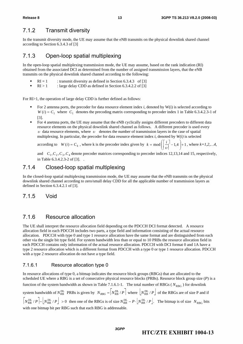
In resource allocations of type 0, a bitmap indicates the resource block groups (RBGs) that are allocated to the scheduled UE where a RBG is a set of consecutive physical resource blocks (PRBs). Resource block group size (P) is a function of the system bandwidth as shown in Table 7.1.6.1-1. The total number of RBGs ( RBGN ) for downlink
system bandwidth of DLRBN PRBs is given by ⎡ ⎤PNNRBG /DL
RB= where ⎣ ⎦PN /DLRB of the RBGs are of size P and if
⎡ ⎤ ⎣ ⎦ 0// DLRB
DLRB >− PNPN then one of the RBGs is of size ⎣ ⎦PNPN /DL
RBDLRB ⋅− . The bitmap is of size RBGN bits
with one bitmap bit per RBG such that each RBG is addressable.
HTC/ZTE EXHIBIT 1004-13
3GPP
3GPP TS 36.213 V8.2.0 (2008-03)14Release 8
Table 7.1.6.1-1: Type 0 Resource Allocation RBG Size vs. Downlink System Bandwidth
System Bandwidth RBG SizeDLRBN (P)
≤10 1 11 -– 26 2
27 -– 6463 3 64 -– 110 4
7.1.6.2 Resource allocation type 1
In resource allocations of type 1, a bitmap of size ⎡ ⎤PN /DLRB indicates to a scheduled UE the PRBs from the set of
PRBs from one of P resource block group subsets. Also P is the resource block group size associated with the system bandwidth as shown in Table 7.1.6.1-1. The portion of the bitmap used to address PRBs in a selected RBG subset has size TYPE1
RBN and is defined as
⎡ ⎤ ⎡ ⎤ 1)(log/ 2DLRB
TYPE1RB −−= PPNN
where ⎡ ⎤PN /DLRB is the overall bitmap size and ⎡ ⎤)(log2 P is the minimum number of bits needed to select one of the
P RBG subsets and one additional bit is used to indicate whether the addressable PRBs of a selected RBG subset is left justified or is right justified (right shifted) where the shift is needed for full resource block granular addressability of all PRBs in a carrier since the number of PRBs in a RBG subset is larger than the PRB addressing portion of the bitmap as
indicated by ⎡ ⎤PNN /DLRB
TYPE1RB < . Each bit in the PRB addressing portion of the bitmap addresses a single
addressable PRB in the selected RBG subset starting at the left most addressable PRB.
7.1.6.3 Resource allocation type 2
In resource allocations of type 2, the resource allocation information indicates to a scheduled UE a set of contiguously allocated physical or virtual resource blocks depending on the setting of a 1-bit flag carried on the associated PDCCH. PRB allocations vary from a single PRB up to a maximum number of PRBs spanning the system bandwidth. For VRB allocations .the resource allocation information consists of a starting VRB number and a number of consecutive VRBs where each VRB is mapped to multiple non-consecutive PRBs.
A type 2 resource allocation field consists of a resource indication value (RIV) corresponding to a starting resource block ( startRB ) and a length in terms of contiguously allocated resource blocks ( CRBsL ). The resource indication value is defined by
if ⎣ ⎦2/)1( DLRBCRBs NL ≤− then
startCRBsDLRB RBLNRIV +−= )1(
else
)1()1( startDLRBCRBs
DLRB
DLRB RBNLNNRIV −−++−=
HTC/ZTE EXHIBIT 1004-14
3GPP
3GPP TS 36.213 V8.2.0 (2008-03)15Release 8
7.2 UE procedure for reporting channel quality indication (CQI), precoding matrix indicator (PMI) and rank indication (RI) The time and frequency resources that can be used by the UE to report CQI, PMI, and RI are controlled by the eNB. For spatial multiplexing, as given in [3], the UE shall determine a RI corresponding to the number of useful transmission layers. For transmit diversity as given in [3], RI is equal to one.
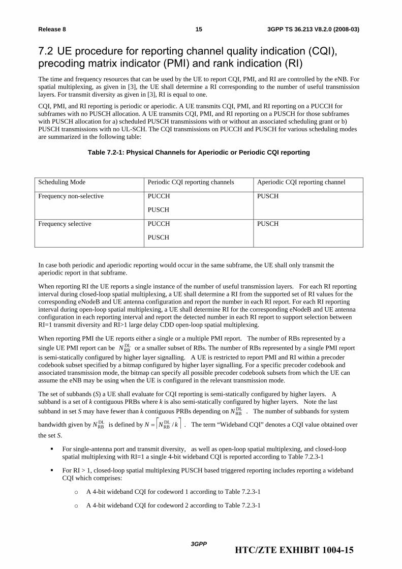
CQI, PMI, and RI reporting is periodic or aperiodic. A UE transmits CQI, PMI, and RI reporting on a PUCCH for subframes with no PUSCH allocation. A UE transmits CQI, PMI, and RI reporting on a PUSCH for those subframes with PUSCH allocation for a) scheduled PUSCH transmissions with or without an associated scheduling grant or b) PUSCH transmissions with no UL-SCH. The CQI transmissions on PUCCH and PUSCH for various scheduling modes are summarized in the following table:
Table 7.2-1: Physical Channels for Aperiodic or Periodic CQI reporting
Scheduling Mode Periodic CQI reporting channels Aperiodic CQI reporting channel
Frequency non-selective PUCCH
PUSCH
PUSCH
Frequency selective PUCCH
PUSCH
PUSCH
In case both periodic and aperiodic reporting would occur in the same subframe, the UE shall only transmit the aperiodic report in that subframe.
When reporting RI the UE reports a single instance of the number of useful transmission layers. For each RI reporting interval during closed-loop spatial multiplexing, a UE shall determine a RI from the supported set of RI values for the corresponding eNodeB and UE antenna configuration and report the number in each RI report. For each RI reporting interval during open-loop spatial multiplexing, a UE shall determine RI for the corresponding eNodeB and UE antenna configuration in each reporting interval and report the detected number in each RI report to support selection between RI=1 transmit diversity and RI>1 large delay CDD open-loop spatial multiplexing.
When reporting PMI the UE reports either a single or a multiple PMI report. The number of RBs represented by a single UE PMI report can be DL
RBN or a smaller subset of RBs. The number of RBs represented by a single PMI report is semi-statically configured by higher layer signalling. A UE is restricted to report PMI and RI within a precoder codebook subset specified by a bitmap configured by higher layer signalling. For a specific precoder codebook and associated transmission mode, the bitmap can specify all possible precoder codebook subsets from which the UE can assume the eNB may be using when the UE is configured in the relevant transmission mode.
The set of subbands (S) a UE shall evaluate for CQI reporting is semi-statically configured by higher layers. A subband is a set of k contiguous PRBs where k is also semi-statically configured by higher layers. Note the last subband in set S may have fewer than k contiguous PRBs depending on DL
RBN . The number of subbands for system
bandwidth given by DLRBN is defined by ⎡ ⎤kNN /DL
RB= . The term “Wideband CQI” denotes a CQI value obtained over the set S.
For single-antenna port and transmit diversity, as well as open-loop spatial multiplexing, and closed-loop spatial multiplexing with RI=1 a single 4-bit wideband CQI is reported according to Table 7.2.3-1
For RI > 1, closed-loop spatial multiplexing PUSCH based triggered reporting includes reporting a wideband CQI which comprises:
o A 4-bit wideband CQI for codeword 1 according to Table 7.2.3-1
o A 4-bit wideband CQI for codeword 2 according to Table 7.2.3-1
HTC/ZTE EXHIBIT 1004-15
3GPP
3GPP TS 36.213 V8.2.0 (2008-03)16Release 8
For RI > 1, closed-loop spatial multiplexing PUCCH based reporting includes separately reporting a 4-bit wideband CQI for codeword 1 according to Table 7.2.3-1 and a wideband spatial differential CQI each with a distinct reporting period and relative subframe offset. The wideband spatial differential CQI comprises:
o A 3-bit wideband spatial differential CQI for codeword 2 = wideband CQI index for codeword 1 – wideband CQI index for codeword 2. The set of exact offset levels is {-4, -3, -2, -1, 0, +1, +2, +3}
7.2.1 Aperiodic/Periodic CQI/PMI/RI Reporting using PUSCH A UE shall perform aperiodic CQI, PMI and RI reporting using the PUSCH upon receiving an indication sent in the scheduling grant.
The aperiodic CQI report size and message format is given by RRC.
The minimum reporting interval for aperiodic reporting of CQI and PMI and RI is 1 subframe. The subband size for CQI shall be the same for transmitter-receiver configurations with and without precoding.
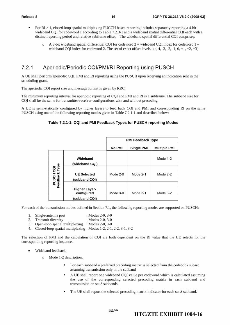
A UE is semi-statically configured by higher layers to feed back CQI and PMI and corresponding RI on the same PUSCH using one of the following reporting modes given in Table 7.2.1-1 and described below:
Table 7.2.1-1: CQI and PMI Feedback Types for PUSCH reporting Modes
PMI Feedback Type
No PMI Single PMI Multiple PMI
Wideband Mode 1-2 (wideband CQI)
UE Selected Mode 2-0 Mode 2-1 Mode 2-2
(subband CQI)
Higher Layer-configured Mode 3-0 Mode 3-1 Mode 3-2
PUSC
H C
QI
Feed
back
Typ
e
(subband CQI) For each of the transmission modes defined in Section 7.1, the following reporting modes are supported on PUSCH:
1. Single-antenna port : Modes 2-0, 3-0 2. Transmit diversity : Modes 2-0, 3-0 3. Open-loop spatial multiplexing : Modes 2-0, 3-0 4. Closed-loop spatial multiplexing : Modes 1-2, 2-1, 2-2, 3-1, 3-2
The selection of PMI and the calculation of CQI are both dependent on the RI value that the UE selects for the corresponding reporting instance.
• Wideband feedback
o Mode 1-2 description:
For each subband a preferred precoding matrix is selected from the codebook subset assuming transmission only in the subband
A UE shall report one wideband CQI value per codeword which is calculated assuming the use of the corresponding selected precoding matrix in each subband and transmission on set S subbands.
The UE shall report the selected precoding matrix indicator for each set S subband.
HTC/ZTE EXHIBIT 1004-16
3GPP
3GPP TS 36.213 V8.2.0 (2008-03)17Release 8
Subband size is given by Table 7.2.1-2.
• Higher Layer-configured subband feedback
o Mode 3-0 description:
A UE shall report a wideband CQI value which is calculated assuming transmission on set S subbands
The UE shall also report one subband CQI value for each set S subband. The subband CQI value is calculated assuming transmission only in the subband The CQI represents channel quality for the first codeword, even when RI>1.
o Mode 3-1 description:
A single precoding matrix is selected from the codebook subset assuming transmission on set S subbands
A UE shall report one subband CQI value per codeword for each set S subband which are calculated assuming the use of the single precoding matrix in all subbands
A UE shall report a wideband CQI value per codeword which is calculated assuming the use of the single precoding matrix in all subbands and transmission on set S subbands
The UE shall report the single selected precoding matrix indicator
o Mode 3-2 description:
For each subband a preferred precoding matrix is selected from the codebook subset assuming transmission only in the subband
A UE shall report one subband CQI value per codeword for each set S subband. The subband CQI value is calculated assuming the use of the corresponding selected precoding matrix in each set S subband.
A UE shall report a wideband CQI value per codeword which is calculated assuming the use of the corresponding selected precoding matrix in each subband and transmission on set S subbands
A UE shall report the selected precoding matrix indicator for each set S subband.
o Subband CQI for each codeword are encoded differentially with respect to their respective wideband CQI using 2-bits as defined by
Subband differential CQI = subband CQI index – wideband CQI index
• Possible subband differential CQI values are {-2, 0, +1, +2}
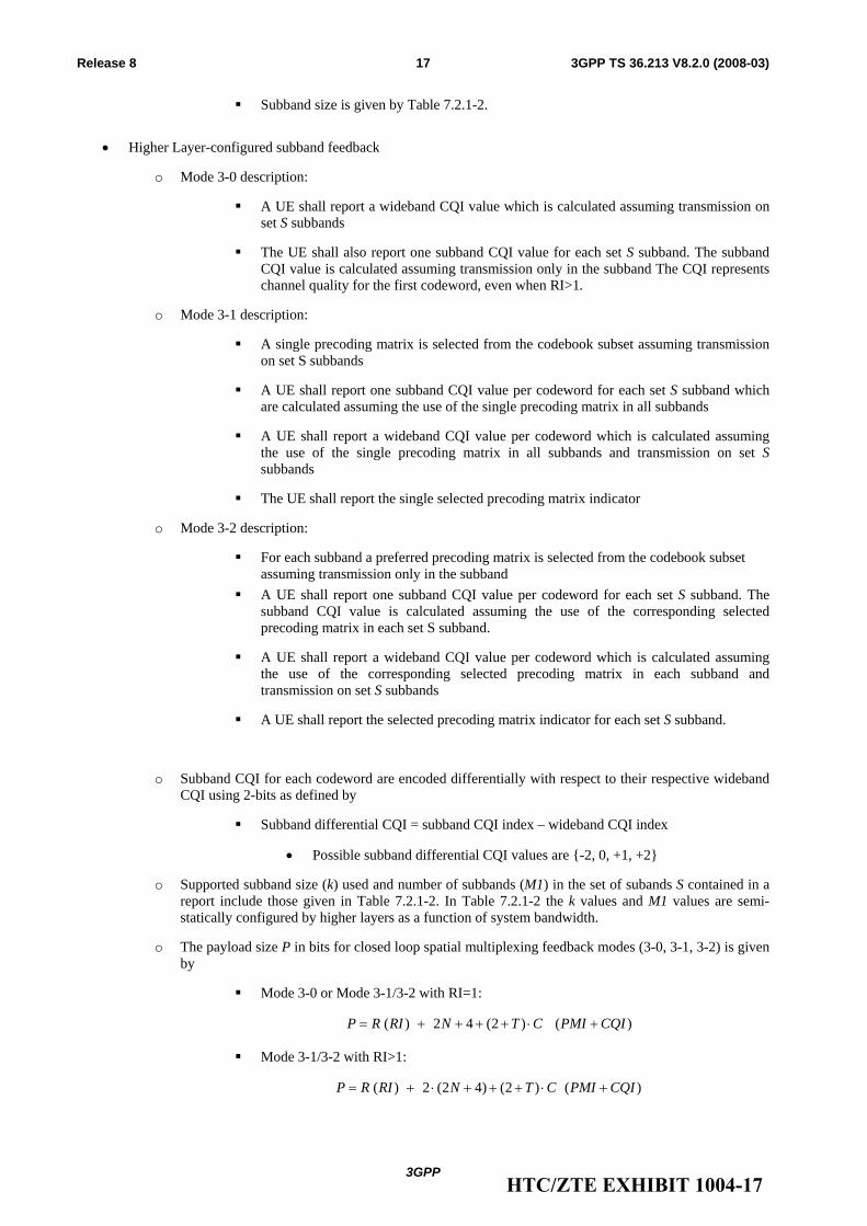
o Supported subband size (k) used and number of subbands (M1) in the set of subands S contained in a report include those given in Table 7.2.1-2. In Table 7.2.1-2 the k values and M1 values are semi-statically configured by higher layers as a function of system bandwidth.
o The payload size P in bits for closed loop spatial multiplexing feedback modes (3-0, 3-1, 3-2) is given by
Mode 3-0 or Mode 3-1/3-2 with RI=1:
)()2(42)( CQIPMICTNRIRP +⋅++++=
Mode 3-1/3-2 with RI>1:
)()2()42(2)( CQIPMICTNRIRP +⋅+++⋅+=
HTC/ZTE EXHIBIT 1004-17
3GPP
3GPP TS 36.213 V8.2.0 (2008-03)18Release 8
where T=2 if 4 antenna ports for common reference symbols are configured, for 2 antenna ports T=y, while for mode 3-0 then T=0
Editor’s note: RAN1 needs to agree on y.
where C=N for mode 3-2 else C=1 for mode 3-1 and C=0 for mode 3-0
where R=2 for up to 4-layer spatial multiplexing else R=1 for up to 2-layer spatial multiplexing and R=0 otherwise
Table 7.2.1-2: Subband Size and #Subband CQI in S vs. System Bandwidth
System Bandwidth Subband Size #Subband CQI in S DLRBN (k) (M1)
6 - 7 (wideband CQI only) 8 - 10 4
11 - 26 4 27 - 63 6 64 - 110 8
• UE-selected subband feedback
o Mode 2-0 description:
The UE shall select a set of M preferred subbands of size k (where k and M are given in Table 7.2.1-3 for each system bandwidth range) within the set of subbands S.
The UE shall also report one CQI value reflecting transmission only over the M selected subbands determined in the previous step. The CQI represents channel quality across all layers irrespective of computed or reported RI.
Additionally, the UE shall also report one wideband CQI value.
o Mode 2-1 description:
A single precoding matrix is selected from the codebook subset assuming transmission on set S subbands
The UE shall perform joint selection of a set of M preferred subbands of size k within the set of subbands S assuming the use of selected preferred precoding matrix.
The UE shall report one CQI value per codeword reflecting transmission only over the selected M preferred subbands and using the same selected preferred single precoding matrix in each of the M subbands
A UE shall report a wideband CQI value per codeword which is calculated assuming the use of the single preferred precoding matrix in all subbands and transmission on set S subbands
A UE shall also report the selected single preferred precoding matrix indicator for all set S subbands
o Mode 2-2 description:
The UE shall perform joint selection of the set of M preferred subbands of size k within the set of subbands S and a preferred single precoding matrix selected from the codebook subset that is preferred to be used for transmission over the M selected subbands.
HTC/ZTE EXHIBIT 1004-18
3GPP
3GPP TS 36.213 V8.2.0 (2008-03)19Release 8
The UE shall report one CQI value per codeword reflecting transmission only over the selected M preferred best subbands and using the same selected single precoding matrix in each of the M subbands.
The UE shall also report the selected single precoding matrix preferred for the M selected subbands.
A single precoding matrix is selected from the codebook subset assuming transmission on set S subbands
A UE shall report a wideband CQI value per codeword which is calculated assuming the use of the single precoding matrix in all subbands and transmission on set S subbands
A UE shall also report the selected single precoding matrix indicator for all set S subbands.
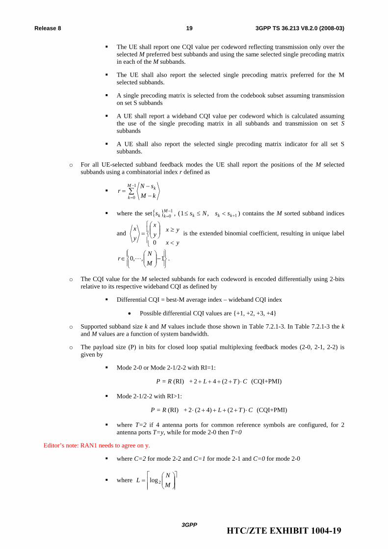
o For all UE-selected subband feedback modes the UE shall report the positions of the M selected subbands using a combinatorial index r defined as
∑−
= −−
=1
0
M
k
k
kMsN
r
where the set{ } 10−=
Mkks , ( 1,1 +<≤≤ kkk ssNs ) contains the M sorted subband indices
and ⎪⎩
⎪⎨⎧
<
≥⎟⎟⎠
⎞⎜⎜⎝
⎛=
yx
yxyx
yx
0 is the extended binomial coefficient, resulting in unique label
⎪⎭
⎪⎬⎫
⎪⎩
⎪⎨⎧
−⎟⎟⎠
⎞⎜⎜⎝
⎛∈ 1,,0
MN
r L .
o The CQI value for the M selected subbands for each codeword is encoded differentially using 2-bits relative to its respective wideband CQI as defined by
Differential CQI = best-M average index – wideband CQI index
• Possible differential CQI values are {+1, +2, +3, +4}
o Supported subband size k and M values include those shown in Table 7.2.1-3. In Table 7.2.1-3 the k and M values are a function of system bandwidth.
o The payload size (P) in bits for closed loop spatial multiplexing feedback modes (2-0, 2-1, 2-2) is given by
Mode 2-0 or Mode 2-1/2-2 with RI=1:
P = R (RI) + CTL ⋅++++ )2(42 (CQI+PMI)
Mode 2-1/2-2 with RI>1:
P = R (RI) + CTL ⋅++++⋅ )2()42(2 (CQI+PMI)
where T=2 if 4 antenna ports for common reference symbols are configured, for 2 antenna ports T=y, while for mode 2-0 then T=0
Editor’s note: RAN1 needs to agree on y.
where C=2 for mode 2-2 and C=1 for mode 2-1 and C=0 for mode 2-0
where ⎥⎥⎥
⎤
⎢⎢⎢
⎡⎟⎟⎠
⎞⎜⎜⎝
⎛=
MN
L 2log
HTC/ZTE EXHIBIT 1004-19
3GPP
3GPP TS 36.213 V8.2.0 (2008-03)20Release 8
where R=2 for up to 4-layer spatial multiplexing else R=1 for up to 2-layer spatial multiplexing and R=0 otherwise
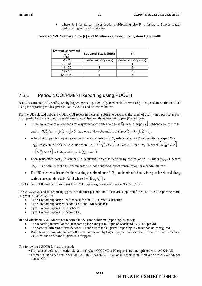
Table 7.2.1-3: Subband Size (k) and M values vs. Downlink System Bandwidth
System Bandwidth DLRBN Subband Size k (RBs) M
6 – 7 (wideband CQI only) (wideband CQI only) 8 – 10 2 1 11 - 26 2 3 27 - 63 3 5 64 - 110 4 6
7.2.2 Periodic CQI/PMI/RI Reporting using PUCCH A UE is semi-statically configured by higher layers to periodically feed back different CQI, PMI, and RI on the PUCCH using the reporting modes given in Table 7.2.2-1 and described below. For the UE-selected subband CQI, a CQI report in a certain subframe describes the channel quality in a particular part or in particular parts of the bandwidth described subsequently as bandwidth part (BP) or parts.
• There are a total of N subbands for a system bandwidth given by DLRBN where ⎣ ⎦kN /DL
RB subbands are of size k
and if ⎡ ⎤ ⎣ ⎦ 0// DLRB
DLRB >− kNkN then one of the subbands is of size ⎣ ⎦kNkN /DL
RBDLRB ⋅− .
• A bandwidth part is frequency-consecutive and consists of JN subbands where J bandwidth parts span S or DLRBN as given in Table 7.2.2-2 and where JN is ⎡ ⎤JkN //DL
RB . Given J>1 then JN is either ⎡ ⎤JkN //DLRB
or ⎡ ⎤ 1//DLRB −JkN depending on DL
RBN , k and J.
• Each bandwidth part j is scanned in sequential order as defined by the equation ),mod( JNj SF= where
SFN is a counter that a UE increments after each subband report transmission for a bandwidth part.
• For UE selected subband feedback a single subband out of JN subbands of a bandwidth part is selected along
with a corresponding L-bit label where ⎡ ⎤JNL 2log= . The CQI and PMI payload sizes of each PUCCH reporting mode are given in Table 7.2.2-3. Three CQI/PMI and RI reporting types with distinct periods and offsets are supported for each PUCCH reporting mode as given in Table 7.2.2-3:
• Type 1 report supports CQI feedback for the UE selected sub-bands • Type 2 report supports wideband CQI and PMI feedback. • Type 3 report supports RI feedback • Type 4 report supports wideband CQI
RI and wideband CQI/PMI are not reported in the same subframe (reporting instance):
• The reporting interval of the RI reporting is an integer multiple of wideband CQI/PMI period. • The same or different offsets between RI and wideband CQI/PMI reporting instances can be configured. • Both the reporting interval and offset are configured by higher layers. In case of collision of RI and wideband
CQI/PMI the wideband CQI/PMI is dropped.
The following PUCCH formats are used: • Format 2 as defined in section 5.4.2 in [3] when CQI/PMI or RI report is not multiplexed with ACK/NAK • Format 2a/2b as defined in section 5.4.2 in [3] when CQI/PMI or RI report is multiplexed with ACK/NAK for
normal CP
HTC/ZTE EXHIBIT 1004-20
3GPP
3GPP TS 36.213 V8.2.0 (2008-03)21Release 8
• Format 2 as defined in section 5.4.2 in [3] when CQI/PMI or RI report is multiplexed with ACK/NAK for extended CP
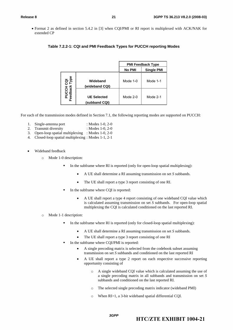
Table 7.2.2-1: CQI and PMI Feedback Types for PUCCH reporting Modes
PMI Feedback Type No PMI Single PMI
Wideband Mode 1-0 Mode 1-1
(wideband CQI)
UE Selected Mode 2-0 Mode 2-1 PUC
CH
CQ
I
Fe
edba
ck T
ype
(subband CQI)
For each of the transmission modes defined in Section 7.1, the following reporting modes are supported on PUCCH:
1. Single-antenna port : Modes 1-0, 2-0 2. Transmit diversity : Modes 1-0, 2-0 3. Open-loop spatial multiplexing : Modes 1-0, 2-0 4. Closed-loop spatial multiplexing : Modes 1-1, 2-1
• Wideband feedback
o Mode 1-0 description:
In the subframe where RI is reported (only for open-loop spatial multiplexing):
• A UE shall determine a RI assuming transmission on set S subbands.
• The UE shall report a type 3 report consisting of one RI.
In the subframe where CQI is reported:
• A UE shall report a type 4 report consisting of one wideband CQI value which is calculated assuming transmission on set S subbands. For open-loop spatial multiplexing the CQI is calculated conditioned on the last reported RI.
o Mode 1-1 description:
In the subframe where RI is reported (only for closed-loop spatial multiplexing):
• A UE shall determine a RI assuming transmission on set S subbands. • The UE shall report a type 3 report consisting of one RI
In the subframe where CQI/PMI is reported: • A single precoding matrix is selected from the codebook subset assuming
transmission on set S subbands and conditioned on the last reported RI • A UE shall report a type 2 report on each respective successive reporting
opportunity consisting of
o A single wideband CQI value which is calculated assuming the use of a single precoding matrix in all subbands and transmission on set S subbands and conditioned on the last reported RI.
o The selected single precoding matrix indicator (wideband PMI)
o When RI>1, a 3-bit wideband spatial differential CQI.
HTC/ZTE EXHIBIT 1004-21
3GPP
3GPP TS 36.213 V8.2.0 (2008-03)22Release 8
• UE Selected subband feedback
o Mode 2-0 description:
In the subframe where RI is reported (only for open-loop spatial multiplexing):
• A UE shall determine a RI assuming transmission on set S subbands.
• The UE shall report a type 3 report consisting of one RI.
In the subframe where wideband CQI is reported:
• The UE shall report a type 4 report on each respective successive reporting opportunity consisting of one wideband CQI value conditioned on the last reported RI.
In the subframe where CQI for the selected subbands is reported:
• The UE shall select the preferred subband within the set of N subbands in each of the J bandwidth parts where J is given in Table 7.2.2-2. For open-loop spatial multiplexing, the selection is conditioned on the last reported RI.
• The UE shall report a type 1 report consisting of one CQI value reflecting transmission only over the selected subband of a bandwidth part determined in the previous step along with the corresponding best subband L-bit label. A type 1 report for each bandwidth part will in turn be reported in respective successive reporting opportunities. The CQI represents channel quality across all layers irrespective of the computed or reported RI. For open-loop spatial multiplexing, the selection is conditioned on the last reported RI
o Mode 2-1 description:
In the subframe where RI is reported: • A UE shall determine a RI assuming transmission on set S subbands. • The UE shall report a type 3 report consisting of one RI.
In the subframe where wideband CQI/PMI is reported: • A single precoding matrix is selected from the codebook subset assuming
transmission on set S subbands and conditioned on the last reported RI.
• A UE shall report a type 2 report on each respective successive reporting opportunity consisting of:
o A wideband CQI value which is calculated assuming the use of a single precoding matrix in all subbands and transmission on set S subbands and conditioned on the last reported RI.
o The selected single precoding matrix indicator (wideband PMI).
o When RI>1, and additional 3-bit wideband spatial differential CQI.
In the subframe where CQI for the selected subbands is reported: • The UE shall select the preferred subband within the set of Nj subbands in each
of the J bandwidth parts where J is given in Table 7.2.2-2 conditioned on the last reported wideband PMI and RI.
• The UE shall report a type 1 report per bandwidth part on each respective successive reporting opportunity consisting of:
o A single CQI value 1 reflecting transmission only over the selected subband of a bandwidth part determined in the previous step along with the corresponding best subband L-bit label conditioned on the last reported wideband PMI and RI.
HTC/ZTE EXHIBIT 1004-22
3GPP
3GPP TS 36.213 V8.2.0 (2008-03)23Release 8
o If RI>1, an additional 3-bit spatial differential CQI represents the difference between CQI value 1 for codeword 1 and CQI value 2 for codeword 2 assuming the use of the most recently reported single precoding matrix in all subbands and transmission on set S subbands.
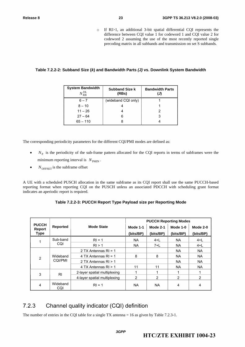
Table 7.2.2-2: Subband Size (k) and Bandwidth Parts (J) vs. Downlink System Bandwidth
System Bandwidth DLRBN
Subband Size k (RBs)
Bandwidth Parts (J)
6 – 7 (wideband CQI only) 1 8 – 10 4 1
11 – 26 4 2 27 – 64 6 3
65 – 110 8 4
The corresponding periodicity parameters for the different CQI/PMI modes are defined as:
• PN is the periodicity of the sub-frame pattern allocated for the CQI reports in terms of subframes were the
minimum reporting interval is PMINN .
• OFFSETN is the subframe offset A UE with a scheduled PUSCH allocation in the same subframe as its CQI report shall use the same PUCCH-based reporting format when reporting CQI on the PUSCH unless an associated PDCCH with scheduling grant format indicates an aperiodic report is required.
Table 7.2.2-3: PUCCH Report Type Payload size per Reporting Mode
PUCCH Reporting Modes Mode 1-1 Mode 2-1 Mode 1-0 Mode 2-0PUCCH
Report Type
Reported Mode State
(bits/BP) (bits/BP) (bits/BP) (bits/BP)
RI = 1 NA 4+L NA 4+L 1 Sub-band CQI RI > 1 NA 7+L NA 4+L
2 TX Antennas RI = 1 NA NA 4 TX Antennas RI = 1 8 8 NA NA 2 TX Antennas RI > 1 NA NA
2 Wideband CQI/PMI
4 TX Antennas RI > 1 11 11 NA NA 2-layer spatial multiplexing 1 1 1 1 3 RI 4-layer spatial multiplexing 2 2 2 2
4 Wideband CQI
RI = 1 NA NA 4 4
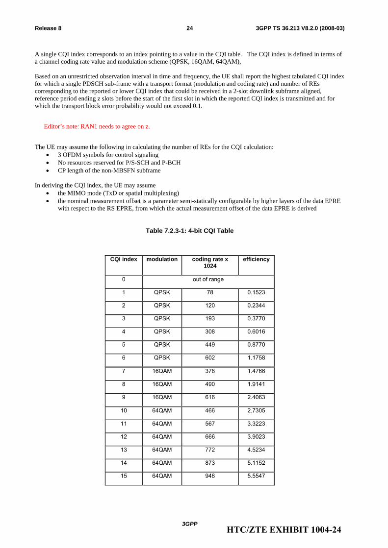
7.2.3 Channel quality indicator (CQI) definition The number of entries in the CQI table for a single TX antenna = 16 as given by Table 7.2.3-1.
HTC/ZTE EXHIBIT 1004-23
3GPP
3GPP TS 36.213 V8.2.0 (2008-03)24Release 8
A single CQI index corresponds to an index pointing to a value in the CQI table. The CQI index is defined in terms of a channel coding rate value and modulation scheme (QPSK, 16QAM, 64QAM), Based on an unrestricted observation interval in time and frequency, the UE shall report the highest tabulated CQI index for which a single PDSCH sub-frame with a transport format (modulation and coding rate) and number of REs corresponding to the reported or lower CQI index that could be received in a 2-slot downlink subframe aligned, reference period ending z slots before the start of the first slot in which the reported CQI index is transmitted and for which the transport block error probability would not exceed 0.1.
Editor’s note: RAN1 needs to agree on z.
The UE may assume the following in calculating the number of REs for the CQI calculation:
• 3 OFDM symbols for control signaling • No resources reserved for P/S-SCH and P-BCH • CP length of the non-MBSFN subframe
In deriving the CQI index, the UE may assume
• the MIMO mode (TxD or spatial multiplexing) • the nominal measurement offset is a parameter semi-statically configurable by higher layers of the data EPRE
with respect to the RS EPRE, from which the actual measurement offset of the data EPRE is derived
Table 7.2.3-1: 4-bit CQI Table
CQI index modulation coding rate x 1024
efficiency
0 out of range
1 QPSK 78 0.1523
2 QPSK 120 0.2344
3 QPSK 193 0.3770
4 QPSK 308 0.6016
5 QPSK 449 0.8770
6 QPSK 602 1.1758
7 16QAM 378 1.4766
8 16QAM 490 1.9141
9 16QAM 616 2.4063
10 64QAM 466 2.7305
11 64QAM 567 3.3223
12 64QAM 666 3.9023
13 64QAM 772 4.5234
14 64QAM 873 5.1152
15 64QAM 948 5.5547
HTC/ZTE EXHIBIT 1004-24
3GPP
3GPP TS 36.213 V8.2.0 (2008-03)25Release 8
7.2.4 Precoding Matrix Indicator (PMI) definition For closed-loop spatial multiplexing transmission, precoding feedback is used for channel dependent codebook based precoding and relies on UEs reporting precoding matrix indicator (PMI). A UE shall report PMI based on the feedback modes described in 7.2.1 and 7.2.2. Each PMI value corresponds to a codebook index given in Table 6.3.4.2.3-1 or Table 6.3.4.2.3-2 of [3]. For open-loop spatial multiplexing transmission, PMI reporting is not supported.
8 Physical uplink shared channel related procedures For FDD, there shall be 8 HARQ processes in the uplink. For FDD, the UE shall upon detection of a PDCCH with DCI format 0 and/or a PHICH transmission in subframe n intended for the UE, adjust the corresponding PUSCH transmission in subframe n+4 according to the PDCCH and PHICH information.
For TDD, the number of HARQ processes shall be determined by the DL/UL configuration. For TDD, the UE shall upon detection of a PDCCH with DCI format 0 and/or a PHICH transmission in subframe n intended for the UE, adjust the corresponding PUSCH transmission in subframe n+k, with k>3 according to the PDCCH and PHICH information
8.1 Resource Allocation for PDCCH DCI Format 0 A resource allocation field in the scheduling grant consists of a resource indication value (RIV) corresponding to a starting resource block ( STARTRB ) and a length in terms of contiguously allocated resource blocks ( CRBsL ). The resource indication value is defined by
if ⎣ ⎦2/)1( ULRBCRBs NL ≤− then
STARTCRBsULRB )1( RBLNRIV +−=
else
)1()1( STARTULRBCRBs
ULRB
ULRB RBNLNNRIV −−++−=
For the case where an odd number of resource block pairs have been configured for PUCCH transmissions and a UE’s PUSCH resource allocation includes PRBs at a carrier band edge then the PRB of the allocated PUSCH band edge PRB pair occupied by the PUCCH resource slot will not be used for the PUSCH.
8.2 UE sounding procedure The following Sounding Reference Symbol (SRS) parameters are UE specific semi-statically configurable by higher layer signalling:
• RPF=2 transmission comb assignment and location
• Duration of SRS transmission (valid until disabled or until the session ends)
• Periodicity of SRS transmissions: {2, 5, 10, 20, 40, 80, 160, 320} ms
• Symbol location in the subframe
• Frequency hopping
HTC/ZTE EXHIBIT 1004-25
3GPP
3GPP TS 36.213 V8.2.0 (2008-03)26Release 8
• Cyclic shift
• Bandwidth of SRS transmission which does not include the PUCCH region
o Narrowband SRS: BW=2 RB if 6ULRB ≤N else BW=2, 4, or 6 RB if 6UL
RB >N
A UE shall not transmit SRS in the case of simultaneous CQI and SRS transmission.
When a UE is RRC configured to support both A/N and SRS transmissions in the same subframe, then the UE shall transmit A/N using a shortened PUCCH format where the A/N symbol corresponding to the SRS location is punctured. When a UE is not RRC configured to support both A/N and SRS transmissions in the same subframe then the UE shall only transmit the A/N using PUCCH format 1a or 1b as defined in Section 5.4.1 of [3].
A UE shall not transmit SRS in the case of simultaneous SR and SRS transmission..
8.2.1 Sounding definition
8.3 UE ACK/NACK procedure When A/N and SR are transmitted in the same sub-frame a UE shall transmit the A/N on its assigned ACK/NACK PUCCH resource for a negative SR transmission and transmit the A/N on its assigned SR PUCCH resource for a positive SR transmission.
When only an ACK/NACK or only a SR is transmitted a UE shall use PUCCH Format 1a or 1b for the ACK/NACK resource and PUCCH Format 1 for the SR resource as defined in section 5.4.1 in [3].
8.4 UE PUSCH Hopping procedure The UE shall perform PUSCH frequency hopping if the single bit frequency hopping (FH) field in a corresponding PDCCH with DCI format 0 is set otherwise no PUSCH frequency hopping is performed.
A UE performing PUSCH frequency hopping shall determine its PUSCH resource allocation for the first slot of a subframe (S1) including the lowest index PRB ( )(1 nnS
PRB ) in subframe n from a subset of the type 2 resource allocation field in a corresponding PDCCH with DCI format 0 received on subframe n-4. For a non-adaptive retransmission of a packet on a dynamically assigned PUSCH resource a UE shall determine its hopping type based on the last received PDCCH with DCI Format 0 associated with the packet. For a PUSCH transmission on a persistently allocated resource on subframe n in the absence of a corresponding PDCCH with a DCI Format 0 in subframe n-4, the UE shall determine its hopping type based on the hopping information in the initial grant that assigned the persistent resource allocation. The initial grant is either a PDCCH with DCI Format 0 or is higher layer signaled.
The subset of the type 2 resource allocation field excludes either 1 or 2 bits used for hopping information as indicated by Table 8.4-1 below where the number of PUSCH resource blocks is defined as PUCCH
RBULRB
PUSCHRB NNN −= where
PUCCHRBN is defined in [3]. The resource indication value (RIV) is defined as
∑−
=−′+−=
2
0STARTCRBs
PUSCHRB
CRBs
)1(L
iiBRLNRIV where 0START =′BR is the first PRB after PUCCH.
A UE performing PUSCH frequency hopping shall use one of two possible PUSCH frequency hopping types based on the hopping information. PUSCH hopping type 1 is described in section 8.4.1 and type 2 is described in section 8.4.2.
HTC/ZTE EXHIBIT 1004-26
3GPP
3GPP TS 36.213 V8.2.0 (2008-03)27Release 8
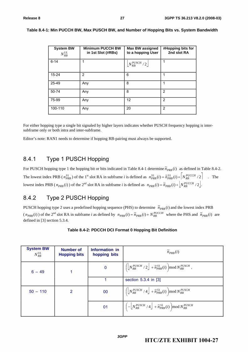
Table 8.4-1: Min PUCCH BW, Max PUSCH BW, and Number of Hopping Bits vs. System Bandwidth
System BW ULRBN
Minimum PUCCH BW in 1st Slot (#RBs)
Max BW assigned to a hopping User
#Hopping bits for 2nd slot RA
6-14 1 ⎣ ⎦2/PUSCHRBN
1
15-24 2 6 1
25-49 Any 8 1
50-74 Any 8 2
75-99 Any 12 2
100-110 Any 20 2
For either hopping type a single bit signaled by higher layers indicates whether PUSCH frequency hopping is inter-subframe only or both intra and inter-subframe.
Editor’s note: RAN1 needs to determine if hopping RB-pairing must always be supported.
8.4.1 Type 1 PUSCH Hopping For PUSCH hopping type 1 the hopping bit or bits indicated in Table 8.4-1 determine )(~ inPRB as defined in Table 8.4-2.
The lowest index PRB ( 1SPRBn ) of the 1st slot RA in subframe i is defined as ⎡ ⎤2/)(~)( 11 PUCCH
RBSPRB
SPRB Ninin += . The
lowest index PRB ( )(inPRB ) of the 2nd slot RA in subframe i is defined as ⎣ ⎦2/)(~)( PUCCHRBPRBPRB Ninin += .
8.4.2 Type 2 PUSCH Hopping PUSCH hopping type 2 uses a predefined hopping sequence (PHS) to determine )(~ inPRB and the lowest index PRB
( )(inPRB ) of the 2nd slot RA in subframe i as defined by PUCCHRBPRBPRB Ninin += )(~)( where the PHS and )(~ inPRB are
defined in [3] section 5.3.4.
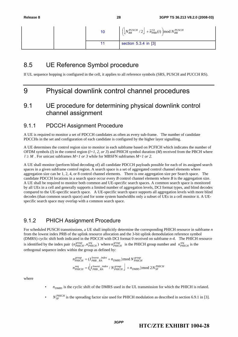
Table 8.4-2: PDCCH DCI Format 0 Hopping Bit Definition
System BW ULRBN
Number of Hopping bits
Information in hopping bits )(~ inPRB
0 ⎣ ⎦ PUSCHRB
SPRB
PUSCHRB NinN mod)(~2/ 1 ⎟
⎠⎞⎜
⎝⎛ + ,
6 – 49 1
1 section 5.3.4 in [3]
00 ⎣ ⎦ PUSCHRB
SPRB
PUSCHRB NinN mod)(~4/ 1 ⎟
⎠⎞⎜
⎝⎛ + 50 – 110 2
01 ⎣ ⎦ PUSCHRB
SPRB
PUSCHRB NinN mod)(~4/ 1 ⎟
⎠⎞⎜
⎝⎛ +−
HTC/ZTE EXHIBIT 1004-27
3GPP
3GPP TS 36.213 V8.2.0 (2008-03)28Release 8
10 ⎣ ⎦ PUSCHRB
SPRB
PUSCHRB NinN mod)(~2/ 1 ⎟
⎠⎞⎜
⎝⎛ +
11 section 5.3.4 in [3]
8.5 UE Reference Symbol procedure If UL sequence hopping is configured in the cell, it applies to all reference symbols (SRS, PUSCH and PUCCH RS).
9 Physical downlink control channel procedures
9.1 UE procedure for determining physical downlink control channel assignment
9.1.1 PDCCH Assignment Procedure A UE is required to monitor a set of PDCCH candidates as often as every sub-frame. The number of candidate PDCCHs in the set and configuration of each candidate is configured by the higher layer signalling.
A UE determines the control region size to monitor in each subframe based on PCFICH which indicates the number of OFDM symbols (l) in the control region (l=1, 2, or 3) and PHICH symbol duration (M) received from the PBCH where
Ml ≥ . For unicast subframes M=1 or 3 while for MBSFN subframes M=1 or 2.
A UE shall monitor (perform blind decoding of) all candidate PDCCH payloads possible for each of its assigned search spaces in a given subframe control region. A search space is a set of aggregated control channel elements where aggregation size can be 1, 2, 4, or 8 control channel elements. There is one aggregation size per Search space. The candidate PDCCH locations in a search space occur every B control channel elements where B is the aggregation size. A UE shall be required to monitor both common and UE-specific search spaces. A common search space is monitored by all UEs in a cell and generally supports a limited number of aggregation levels, DCI format types, and blind decodes compared to the UE-specific search space. A UE-specific search space supports all aggregation levels with more blind decodes (than common search space) and for some system bandwidths only a subset of UEs in a cell monitor it. A UE-specific search space may overlap with a common search space.
9.1.2 PHICH Assignment Procedure For scheduled PUSCH transmissions, a UE shall implicitly determine the corresponding PHICH resource in subframe n from the lowest index PRB of the uplink resource allocation and the 3-bit uplink demodulation reference symbol (DMRS) cyclic shift both indicated in the PDCCH with DCI format 0 received on subframe n-4. The PHICH resource is identified by the index pair ),( seq
PHICHgroupPHICH nn where group
PHICHn is the PHICH group number and seqPHICHn is the
orthogonal sequence index within the group as defined by:
⎣ ⎦ PHICHSFDMRS
groupPHICH
indexlowestRAPRB
seqPHICH
groupPHICHDMRS
indexlowestRAPRB
groupPHICH
NnNIn
NnIn
2mod)/(
mod)(
__
__
+=
+=
where
• DMRSn is the cyclic shift of the DMRS used in the UL transmission for which the PHICH is related.
• PHICHSFN is the spreading factor size used for PHICH modulation as described in section 6.9.1 in [3].
HTC/ZTE EXHIBIT 1004-28
3GPP
3GPP TS 36.213 V8.2.0 (2008-03)29Release 8
• indexlowestRAPRBI _
_ is the lowest index PRB of the uplink resource allocation
• groupPHICHN is the number of PHICH groups configured
10 Physical uplink control channel procedures
10.1 UE procedure for determining physical uplink control channel assignment
The resource blocks reserved for PUCCHs in a sub-frame are semi-statically configured.
For a PDSCH transmission on subframe n corresponding to a PDCCH with DCI format 1A/1/2 received on subframe n-4, the UE shall determine the PUCCH index for ACK/NACK implicitly from the lowest CCE index used to construct the associated PDCCH.
For each PDSCH transmission corresponding to a configured scheduling assignment the UE shall use a PUCCH index for ACK/NACK previously received explicitly from higher layer signalling associated with the configured scheduling assignment. While the configured scheduling assignment is valid a UE shall continue to use the explicitly signalled PUCCH index for ACK/NACK for a PDSCH transmission on subframe n when no corresponding PDCCH with DCI format 1A/1/2 was received on subframe n-4.
10.2 Uplink ACK/NACK timing For FDD, the UE shall upon detection of a PDSCH transmission in subframe n intended for the UE and for which an ACK/NACK shall be provided, transmit the ACK/NACK response in subframe n+4.
For TDD, the UE shall upon detection of a PDSCH transmission in subframe n intended for the UE and for which an ACK/NACK shall be provided, transmit the ACK/NACK response in UL subframe n+k, with k>3.
For TDD, the use of a single ACK/NACK response for providing HARQ feedback for multiple PDSCH transmissions is supported by performing logical AND of all the corresponding individual PDSCH transmission ACK/NACKs.
HTC/ZTE EXHIBIT 1004-29
3GPP
3GPP TS 36.213 V8.2.0 (2008-03)30Release 8
Annex A (informative): Change history
Change history Date TSG # TSG Doc. CR Rev Subject/Comment Old New 2006-09 Draft version created 0.0.02006-10 Endorsed by RAN1 0.0.0 0.1.02007-01 Inclusion of decisions from RAN1#46bis and RAN1#47 0.1.0 0.1.12007-01 Endorsed by RAN1 0.1.1 0.2.02007-02 Inclusion of decisions from RAN1#47bis 0.2.0 0.2.12007-02 Endorsed by RAN1 0.2.1 0.3.02007-02 Editor’s version including decisions from RAN1#48 & RAN1#47bis 0.3.0 0.3.12007-03 Updated Editor’s version 0.3.1 0.3.22007-03 RAN#35 RP-070171 For information at RAN#35 0.3.2 1.0.02007-03 Random access text modified to better reflect RAN1 scope 1.0.0 1.0.12007-03 Updated Editor’s version 1.0.1 1.0.22007-03 Endorsed by RAN1 1.0.2 1.1.02007-05 Updated Editor’s version 1.1.0 1.1.12007-05 Updated Editor’s version 1.1.1 1.1.22007-05 Endorsed by RAN1 1.1.2 1.2.02007-08 Updated Editor’s version 1.2.0 1.2.12007-08 Updated Editor’s version – uplink power control from RAN1#49bis 1.2.1 1.2.22007-08 Endorsed by RAN1 1.2.2 1.3.02007-09 Updated Editor’s version reflecting RAN#50 decisions 1.3.0 1.3.12007-09 Updated Editor’s version reflecting comments 1.3.1 1.3.22007-09 Updated Editor’s version reflecting further comments 1.3.2 1.3.32007-09 Updated Editor’s version reflecting further comments 1.3.3 1.3.42007-09 Updated Edtior’s version reflecting further comments 1.3.4 1.3.52007-09 RAN#37 RP-070731 Endorsed by RAN1 1.3.5 2.0.02007-09 RAN#37 RP-070737 For approval at RAN#37 2.0.0 2.1.012/09/07 RAN_37 RP-070737 - - Approved version 2.1.0 8.0.028/11/07 RAN_38 RP-070949 0001 2 Update of 36.213 8.0.0 8.1.005/03/08 RAN_39 RP-080145 0002 - Update of TS36.213 according to changes listed in cover sheet 8.1.0 8.2.0
HTC/ZTE EXHIBIT 1004-30


![Test Plan for 2x2 Downlink MIMO and Transmit Diversity ... · [1] 3GPP TR 37.977: Verification of radiated multi-antenna reception performance of User Equipment (UE) [2] 3GPP TS 36.213:](https://img.pdfslide.us/doc/110x75/60112fa63e612334df2c0ae4/test-plan-for-2x2-downlink-mimo-and-transmit-diversity-1-3gpp-tr-37977-verification.jpg)