Embed Size (px)
Citation preview
3GPP TS 26.132 V10.2.0 (2011-09) Technical Specification
3rd Generation Partnership Project;
Technical Specification Group Services and System Aspects;
Speech and video telephony terminal acoustic test
specification
(Release 10)
The present document has been developed within the 3rd Generation Partnership Project (3GPP TM) and may be further elaborated for the purposes of 3GPP.
The present document has not been subject to any approval process by the 3GPP Organizational Partners and shall not be implemented.
This Specification is provided for future development work within 3GPP only. The Organizational Partners accept no liability for any use of this
Specification.
Specifications and reports for implementation of the 3GPP TM system should be obtained via the 3GPP Organizational Partners' Publications Offices.
3GPP
3GPP TS 26.132 V10.2.0 (2011-09) 2 Release 10
Keywords
UMTS, 3,1kHz, telephony, acoustic, testing, video, LTE
3GPP
Postal address
3GPP support office address
650 Route des Lucioles - Sophia Antipolis Valbonne - FRANCE
Tel.: +33 4 92 94 42 00 Fax: +33 4 93 65 47 16
Internet
http://www.3gpp.org
Copyright Notification
No part may be reproduced except as authorized by written permission.
The copyright and the foregoing restriction extend to reproduction in all media.
© 2011, 3GPP Organizational Partners (ARIB, ATIS, CCSA, ETSI, TTA, TTC).
All rights reserved.
UMTS™ is a Trade Mark of ETSI registered for the benefit of its members
3GPP™ is a Trade Mark of ETSI registered for the benefit of its Members and of the 3GPP Organizational Partners
LTE™ is a Trade Mark of ETSI currently being registered for the benefit of its Members and of the 3GPP Organizational Partners
GSM® and the GSM logo are registered and owned by the GSM Association
3GPP
3GPP TS 26.132 V10.2.0 (2011-09) 3 Release 10
Contents
Foreword ............................................................................................................................................................ 6
Introduction ........................................................................................................................................................ 6
1 Scope ........................................................................................................................................................ 7
2 References ................................................................................................................................................ 7
3 Definitions, symbols and abbreviations ................................................................................................... 8 3.1 Definitions ......................................................................................................................................................... 8 3.2 Abbreviations ..................................................................................................................................................... 9
4 Interfaces .................................................................................................................................................. 9
5 Test configurations ................................................................................................................................. 10 5.1 Setup for terminals ........................................................................................................................................... 10 5.1.1 Setup for handset terminals ........................................................................................................................ 11 5.1.2 Setup for headset terminals ........................................................................................................................ 12 5.1.3 Setup for hands-free terminals .................................................................................................................... 12 5.1.3.1 Vehicle-mounted hands-free ................................................................................................................. 12 5.1.3.2 Desktop hands-free ............................................................................................................................... 13 5.1.3.3 Hand-held hands-free ............................................................................................................................ 13 5.1.3.4 Softphone including speakers and microphone ..................................................................................... 15 5.1.3.5 Softphone with separate speakers ......................................................................................................................... 17 5.1.4 Position and calibration of HATS .............................................................................................................. 21 5.2 Setup of the electrical interfaces ...................................................................................................................... 21 5.2.1 Codec approach and specification .............................................................................................................. 21 5.2.2 Direct digital processing approach ............................................................................................................. 22 5.3 Accuracy of test equipment .............................................................................................................................. 22 5.4 Test signals ...................................................................................................................................................... 23 5.5 Void ................................................................................................................................................................. 23 5.5.1 Void............................................................................................................................................................ 24 5.5.2 Void............................................................................................................................................................ 24
6 Test conditions ....................................................................................................................................... 24 6.1 Environmental conditions ................................................................................................................................ 24 6.1.1 Handset and headset terminals ................................................................................................................... 24 6.1.2 Hands-free terminals .................................................................................................................................. 24 6.2 System simulator conditions ............................................................................................................................ 25
7 Narrowband telephony transmission performance test methods ........................................................... 25 7.1 Applicability .................................................................................................................................................... 25 7.2 Overall loss/loudness ratings ........................................................................................................................... 25 7.2.1 General ....................................................................................................................................................... 25 7.2.2 Connections with handset UE..................................................................................................................... 26 7.2.2.1 Sending loudness rating (SLR) ............................................................................................................. 26 7.2.2.2 Receiving loudness rating (RLR) .......................................................................................................... 26 7.2.3 Connections with desktop and vehicle-mounted hands-free UE ................................................................ 26 7.2.3.1 Sending loudness rating (SLR) ............................................................................................................. 26 7.2.3.2 Receiving Loudness Rating (RLR) ....................................................................................................... 27 7.2.4 Connections with hand-held hands-free UE ............................................................................................... 27 7.2.4.1 Sending loudness rating (SLR) ............................................................................................................. 27 7.2.4.2 Receiving loudness rating (RLR) .......................................................................................................... 28 7.2.5 Connections with headset UE ..................................................................................................................... 28 7.3 Idle channel noise (handset and headset UE) ................................................................................................... 28 7.3.1 Sending ....................................................................................................................................................... 28 7.3.2 Receiving.................................................................................................................................................... 29 7.4 Sensitivity/frequency characteristics ................................................................................................................ 29 7.4.1 Handset and headset UE sending ............................................................................................................... 29
3GPP
3GPP TS 26.132 V10.2.0 (2011-09) 4 Release 10
7.4.2 Handset and headset UE receiving ............................................................................................................. 29 7.4.3 Desktop and vehicle-mounted hands-free UE sending ............................................................................... 30 7.4.4 Desktop and vehicle-mounted hands-free UE receiving ............................................................................. 30 7.4.5 Hand-held hands-free UE sending .............................................................................................................. 30 7.4.6 Hand-held hands-free UE receiving ........................................................................................................... 31 7.5 Sidetone characteristics .................................................................................................................................... 31 7.5.1 Connections with handset UE..................................................................................................................... 31 7.5.1.1 void 31 7.5.1.2 Connections with handset UE – HATS method .................................................................................................... 31 7.5.2 Headset UE ................................................................................................................................................ 32 7.5.3 Hands-free UE (all categories) ................................................................................................................... 32 7.6 Stability loss ..................................................................................................................................................... 32 7.7 Acoustic echo control ...................................................................................................................................... 33 7.7.1 General ....................................................................................................................................................... 33 7.7.2 Acoustic echo control in a hands-free UE .................................................................................................. 33 7.7.3 Acoustic echo control in handset UE ......................................................................................................... 34 7.7.4 Acoustic echo control in a headset UE ....................................................................................................... 35 7.8 Distortion ......................................................................................................................................................... 36 7.8.1 Sending distortion ...................................................................................................................................... 36 7.8.2 Receiving.................................................................................................................................................... 37 7.9 Ambient noise rejection ................................................................................................................................... 38
8 Wideband telephony transmission performance test methods ............................................................... 40 8.1 Applicability .................................................................................................................................................... 40 8.2 Overall loss/loudness ratings ........................................................................................................................... 40 8.2.1 General ....................................................................................................................................................... 40 8.2.2 Connections with handset UE..................................................................................................................... 40 8.2.2.1 Sending loudness rating (SLR) ............................................................................................................. 40 8.2.2.2 Receiving loudness rating (RLR) .......................................................................................................... 41 8.2.3 Connections with desktop and vehicle-mounted hands-free UE ................................................................ 41 8.2.3.1 Sending loudness rating (SLR) ............................................................................................................. 41 8.2.3.2 Receiving loudness rating (RLR) .......................................................................................................... 42 8.2.4 Connections with hand-held hands-free UE ............................................................................................... 42 8.2.4.1 Sending loudness rating (SLR) ............................................................................................................. 42 8.2.4.2 Receiving loudness rating (RLR) .......................................................................................................... 42 8.2.5 Connections with headset UE ..................................................................................................................... 43 8.3 Idle channel noise (handset and headset UE) ................................................................................................... 43 8.3.1 Sending ....................................................................................................................................................... 43 8.3.2 Receiving.................................................................................................................................................... 44 8.4 Sensitivity/frequency characteristics ................................................................................................................ 44 8.4.1 Handset and headset UE sending ............................................................................................................... 44 8.4.2 Handset and headset UE receiving ............................................................................................................. 44 8.4.3 Desktop and vehicle-mounted hands-free UE sending ............................................................................... 45 8.4.4 Desktop and vehicle-mounted hands-free UE receiving ............................................................................. 45 8.4.5 Hand-held hands-free UE sending .............................................................................................................. 45 8.4.6 Hand-held hands-free UE receiving ........................................................................................................... 46 8.5 Sidetone characteristics .................................................................................................................................... 46 8.5.1 Connections with handset UE..................................................................................................................... 46 8.5.2 Headset UE ................................................................................................................................................ 46 8.5.3 Hands-free UE (all categories) ................................................................................................................... 47 8.5.4 Sidetone delay for handset or headset ........................................................................................................ 47 8.6 Stability loss ..................................................................................................................................................... 47 8.7 Acoustic echo control ...................................................................................................................................... 49 8.7.1 General ....................................................................................................................................................... 49 8.7.2 Acoustic echo control in a hands-free UE .................................................................................................. 49 8.7.3 Acoustic echo control in a handset UE ....................................................................................................... 49 8.7.4 Acoustic echo control in a headset UE ....................................................................................................... 50 8.8 Distortion ......................................................................................................................................................... 51 8.8.1 Sending distortion ...................................................................................................................................... 51
3GPP
3GPP TS 26.132 V10.2.0 (2011-09) 5 Release 10
8.8.2 Receiving.................................................................................................................................................... 52 8.9 Ambient noise rejection ................................................................................................................................... 54
Annex A: Interpolation method for diffuse-field correction (normative) ................. 56
Annex B (informative): Change history ............................................................................................... 57
3GPP
3GPP TS 26.132 V10.2.0 (2011-09) 6 Release 10
Foreword
This Technical Specification has been produced by the 3GPP.
The contents of the present document are subject to continuing work within the TSG and may change following formal
TSG approval. Should the TSG modify the contents of this TS, it will be re-released by the TSG with an identifying
change of release date and an increase in version number as follows:
Version x.y.z
where:
x the first digit:
1 presented to TSG for information;
2 presented to TSG for approval;
3 or greater indicates TSG approved document under change control.
y the second digit is incremented for all changes of substance, i.e. technical enhancements, corrections, updates,
etc.
z the third digit is incremented when editorial only changes have been incorporated in the specification.
Introduction
The present document specifies test methods to allow the minimum performance requirements for the acoustic
characteristics of GSM and 3G terminals when used to provide narrowband or wideband telephony to be assessed.
The objective for narrowband services is to reach a quality as close as possible to ITU-T standards for PSTN circuits.
However, due to technical and economic factors, there cannot be full compliance with the general characteristics of
international telephone connections and circuits recommended by the ITU-T.
The performance requirements are specified in TS 26.131; the test methods and considerations are specified in the main
body of the text.
3GPP
3GPP TS 26.132 V10.2.0 (2011-09) 7 Release 10
1 Scope
The present document is applicable to any terminal capable of supporting narrowband or wideband telephony, either as
a stand-alone service or as the telephony component of a multimedia service. The present document specifies test
methods to allow the minimum performance requirements for the acoustic characteristics of GSM and 3G terminals
when used to provide narrowband or wideband telephony to be assessed.
2 References
The following documents contain provisions which, through reference in this text, constitute provisions of the present
document.
References are either specific (identified by date of publication, edition number, version number, etc.) or
non-specific.
For a specific reference, subsequent revisions do not apply.
For a non-specific reference, the latest version applies. In the case of a reference to a 3GPP document (including
a GSM document), a non-specific reference implicitly refers to the latest version of that document in the same
Release as the present document.
[1] 3GPP TS 26.131: "Terminal Acoustic Characteristics for Telephony; Requirements".
[2] ITU-T Recommendation B.12 (1988): "Use of the decibel and the neper in telecommunications".
[3] ITU-T Recommendation G.103 (1998): "Hypothetical reference connections".
[4] ITU-T Recommendation G.111 (1993): "Loudness ratings (LRs) in an international connection".
[5] ITU-T Recommendation G.121 (1993): "Loudness ratings (LRs) of national systems".
[6] ITU-T Recommendation G.122 (1993): "Influence of national systems on stability and talker echo
in international connections".
[7] ITU-T Recommendation G.711 (1988): "Pulse code modulation (PCM) of voice frequencies".
[8] ITU-T Recommendation P.11 (1993): "Effect of transmission impairments".
[9] ITU-T Recommendation P.38 (1993): "Transmission characteristics of operator telephone systems
(OTS)".
[10] ITU-T Recommendation P.50 (1993): "Artificial voices".
[11] 3GPP TS 03.58 (Release 1997): "Digital Cellular Telecommunications System (Phase 2+)
Characterization test methods and quality assessment for hands-free mobiles".
[12] IEC Publication 60651: “Sound Level Meters”.
[13] ITU-T Recommendation P.51 (1996): "Artificial mouth".
[14] ITU-T Recommendation P.57 (2005): "Artificial ears".
[15] ITU-T Recommendation P.58 (1996): "Head and torso simulator for telephonometry."
[16] ITU-T Recommendation P.79 (2007) with Annex A: "Calculation of loudness ratings for telephone
sets."
[17] 3GPP TS 06.77 (R99): “Minimum Performance Requirements for Noise Suppresser Application to
the AMR Speech Encoder”.

3GPP
3GPP TS 26.132 V10.2.0 (2011-09) 8 Release 10
[18] ITU-T Recommendation P.64: "Determination of sensitivity/frequency characteristics of local
telephone systems".
[19] ITU-T Recommendation P.581: "Use of head and torso simulator (HATS) for hands-free and
handset terminal testing".
[20] ITU-T Recommendation P.340: "Transmission characteristics and speech quality parameters of
hands-free terminals".
[21] ITU-T Recommendation G.712: "Transmission performance characteristics of pulse code
modulation channels".
[22] ITU-T Recommendation P.501: "Test signals for use in telephonometry".
[23] ITU-T Recommendation O.41: "Psophometer for use on telephone-type circuits".
[24] ITU-T Recommendation O.131: "Quantizing distortion measuring equipment using a pseudo-
random noise test signal".
[25] ISO 9614: "Acoustics - Determination of sound power levels of noise sources using sound
intensity".
[26] ISO 3745: "Acoustics - Determination of sound power levels of noise sources using sound pressure
- Precision methods for anechoic and hemi-anechoic rooms".
[27] ITU-T Recommendation O.132: "Quantizing distortion measuring equipment using a sinusoidal
test signal".
[28] ETSI TS 103 737: "Transmission requirements for narrowband wireless terminals (handset and
headset) from a QoS perspective as perceived by the user".
[29] ETSI TS 103 738: "Transmission requirements for narrowband wireless terminals (handsfree) from
a QoS perspective as perceived by the user".
[30] ETSI TS 103 739: "Transmission requirements for wideband wireless terminals (handset and
headset) from a QoS perspective as perceived by the user".
[31] ETSI TS 103 740: "Transmission requirements for wideband wireless terminals (handsfree) from a
QoS perspective as perceived by the user".
[32] ITU-T Recommendation P.380: "Electro-acoustic measurements on headsets".
3 Definitions, symbols and abbreviations
3.1 Definitions
For the purposes of the present document the term narrowband refers to signals sampled at 8 kHz; wideband refers to
signals sampled at 16 kHz.
For the purposes of the present document, the terms dB, dBr, dBm0, dBm0p and dBA, shall be interpreted as defined in
ITU-T Recommendation B.12 [2]; the term dBPa shall be interpreted as the sound pressure level relative to 1 pascal
expressed in dB (0 dBPa is equivalent to 94 dB SPL).
A 3GPP softphone is a telephony system running on a general purpose computer or PDA complying with the 3GPP
terminal acoustic requirements (TS 26.131 and 26.132).
3GPP
3GPP TS 26.132 V10.2.0 (2011-09) 9 Release 10
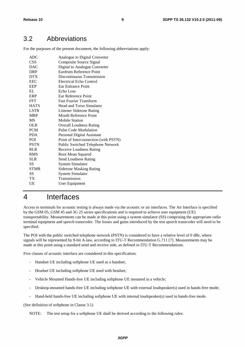
3.2 Abbreviations
For the purposes of the present document, the following abbreviations apply:
ADC Analogue to Digital Converter
CSS Composite Source Signal
DAC Digital to Analogue Converter
DRP Eardrum Reference Point
DTX Discontinuous Transmission
EEC Electrical Echo Control
EEP Ear Entrance Point
EL Echo Loss
ERP Ear Reference Point
FFT Fast Fourier Transform
HATS Head and Torso Simulator
LSTR Listener Sidetone Rating
MRP Mouth Reference Point
MS Mobile Station
OLR Overall Loudness Rating
PCM Pulse Code Modulation
PDA Personal Digital Assistant
POI Point of Interconnection (with PSTN)
PSTN Public Switched Telephone Network
RLR Receive Loudness Rating
RMS Root Mean Squared
SLR Send Loudness Rating
SS System Simulator
STMR Sidetone Masking Rating
SS System Simulator
TX Transmission
UE User Equipment
4 Interfaces
Access to terminals for acoustic testing is always made via the acoustic or air interfaces. The Air Interface is specified
by the GSM 05, GSM 45 and 3G 25 series specifications and is required to achieve user equipment (UE)
transportability. Measurements can be made at this point using a system simulator (SS) comprising the appropriate radio
terminal equipment and speech transcoder. The losses and gains introduced by the test speech transcoder will need to be
specified.
The POI with the public switched telephone network (PSTN) is considered to have a relative level of 0 dBr, where
signals will be represented by 8-bit A-law, according to ITU-T Recommendation G.711 [7]. Measurements may be
made at this point using a standard send and receive side, as defined in ITU-T Recommendations.
Five classes of acoustic interface are considered in this specification:
- Handset UE including softphone UE used as a handset;
- Headset UE including softphone UE used with headset;
- Vehicle Mounted Hands-free UE including softphone UE mounted in a vehicle;
- Desktop-mounted hands-free UE including softphone UE with external loudspeaker(s) used in hands-free mode;
- Hand-held hands-free UE including softphone UE with internal loudspeaker(s) used in hands-free mode.
(See definition of softphone in Clause 3.1)
NOTE: The test setup for a softphone UE shall be derived according to the following rules:
3GPP
3GPP TS 26.132 V10.2.0 (2011-09) 10 Release 10
- When using a softphone UE as a handset: the test setup shall correspond to handset mode.
- When using a softphone UE with headset: the test setup shall correspond to headset mode.
- When a softphone UE is mounted in a vehicle: the test setup shall correspond to vehicle-mounted hands-
free mode.
- When using a softphone UE in hands-free mode:
- When using internal loudspeaker(s), the test setup shall correspond to hand-held hands-free.
- When using external loudspeaker(s), the test setup shall correspond to desktop-mounted hands-free.
5 Test configurations
This section describes the test setups for terminal acoustic testing.
NOTE: If the terminal has several mechanical configurations (e.g., sliding design open or closed), all
manufacturer-defined configurations shall be tested.
5.1 Setup for terminals
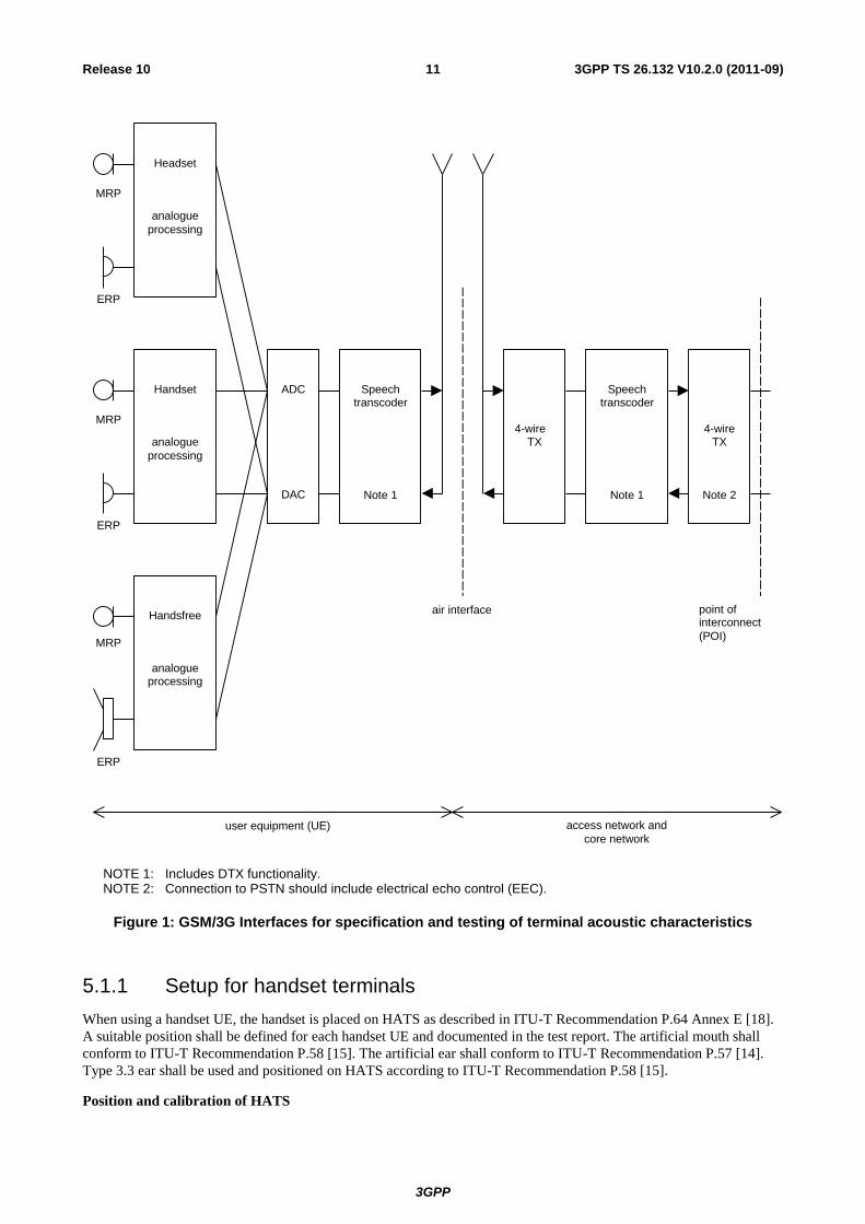
The general access to terminals is described in figure 1. The preferred acoustic access to GSM and 3G terminals is the
most realistic simulation of the “average” subscriber. This can be made by using HATS (head and torso simulator), with
appropriate ear simulation and appropriate mountings of handset terminals to the HATS in a realistic but reproducible
way. Hands-free terminals shall use the HATS or free field microphone techniques in a realistic but reproducible way.
HATS is described in ITU-T Recommendation P.58 [15], appropriate ears are described in ITU-T Recommendation
P.57 [14] (Type 3.3), proper positioning of handsets in realistic conditions is found in ITU-T Recommendation P.64,
and the test setups for various types of hands-free terminals can be found in ITU-T Recommendation P.581.
Unless stated otherwise, if a volume control is provided, the setting is chosen such that the nominal RLR is met as close
as possible.
The preferred way of testing is the connection of a terminal to the system simulator with exact defined settings and
access points. The test sequences are fed in either electrically using a reference codec, using the direct signal processing
approach, or acoustically using ITU-T specified devices.
3GPP
3GPP TS 26.132 V10.2.0 (2011-09) 11 Release 10
MRP
ERP
MRP
ERP
MRP
ERP
ADC
DAC
Speechtranscoder
Note 1
Handset
analogue
processing
Headset
analogue
processing
Handsfree
analogueprocessing
Speechtranscoder
Note 1
4-wireTX
4-wireTX
Note 2
point ofinterconnect
(POI)
air interface
user equipment (UE) access network and
core network
NOTE 1: Includes DTX functionality. NOTE 2: Connection to PSTN should include electrical echo control (EEC).
Figure 1: GSM/3G Interfaces for specification and testing of terminal acoustic characteristics
5.1.1 Setup for handset terminals
When using a handset UE, the handset is placed on HATS as described in ITU-T Recommendation P.64 Annex E [18].
A suitable position shall be defined for each handset UE and documented in the test report. The artificial mouth shall
conform to ITU-T Recommendation P.58 [15]. The artificial ear shall conform to ITU-T Recommendation P.57 [14].
Type 3.3 ear shall be used and positioned on HATS according to ITU-T Recommendation P.58 [15].
Position and calibration of HATS
3GPP
3GPP TS 26.132 V10.2.0 (2011-09) 12 Release 10
The sending and receiving characteristics shall be tested with the HATS. It shall be indicated what application force was
used. If not stated otherwise in TS 26.131, an application force of 8 ± 2 N shall be used.
The horizontal positioning of the HATS reference plane shall be guaranteed within ± 2º.
5.1.2 Setup for headset terminals
Recommendations for the setup and positioning of headsets are given in ITU-T Recommendation P.380. If not stated
otherwise, headsets shall be placed in their recommended wearing position. Some insert earphones might not fit properly
in Type 3.3 ear simulators. For such insert type headsets, an ITU-T Recommendation P.57 [14] Type 2 ear simulator
may be used in conjunction with the HATS mouth simulator. The HATS should be equipped with two artificial ears as
specified in ITU-T Recommendation P.57 [14]. For binaural headsets two artificial ears are required.
5.1.3 Setup for hands-free terminals
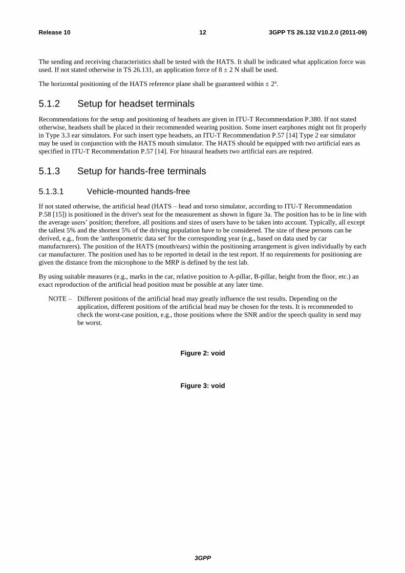
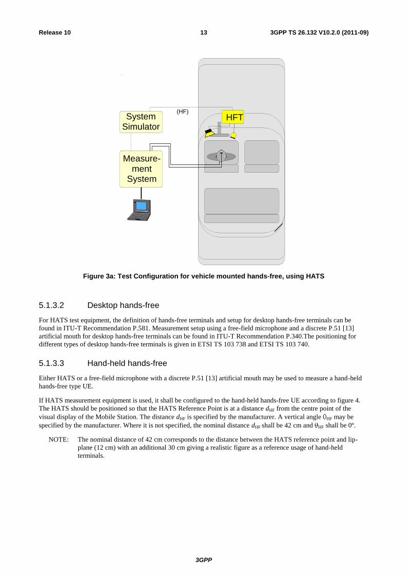
5.1.3.1 Vehicle-mounted hands-free
If not stated otherwise, the artificial head (HATS – head and torso simulator, according to ITU-T Recommendation
P.58 [15]) is positioned in the driver's seat for the measurement as shown in figure 3a. The position has to be in line with
the average users‟ position; therefore, all positions and sizes of users have to be taken into account. Typically, all except
the tallest 5% and the shortest 5% of the driving population have to be considered. The size of these persons can be
derived, e.g., from the 'anthropometric data set' for the corresponding year (e.g., based on data used by car
manufacturers). The position of the HATS (mouth/ears) within the positioning arrangement is given individually by each
car manufacturer. The position used has to be reported in detail in the test report. If no requirements for positioning are
given the distance from the microphone to the MRP is defined by the test lab.
By using suitable measures (e.g., marks in the car, relative position to A-pillar, B-pillar, height from the floor, etc.) an
exact reproduction of the artificial head position must be possible at any later time.
NOTE – Different positions of the artificial head may greatly influence the test results. Depending on the
application, different positions of the artificial head may be chosen for the tests. It is recommended to
check the worst-case position, e.g., those positions where the SNR and/or the speech quality in send may
be worst.
Figure 2: void
Figure 3: void
3GPP
3GPP TS 26.132 V10.2.0 (2011-09) 13 Release 10
HFT
Measure-ment
System
System Simulator
(HF)
Figure 3a: Test Configuration for vehicle mounted hands-free, using HATS
5.1.3.2 Desktop hands-free
For HATS test equipment, the definition of hands-free terminals and setup for desktop hands-free terminals can be
found in ITU-T Recommendation P.581. Measurement setup using a free-field microphone and a discrete P.51 [13]
artificial mouth for desktop hands-free terminals can be found in ITU-T Recommendation P.340.The positioning for
different types of desktop hands-free terminals is given in ETSI TS 103 738 and ETSI TS 103 740.
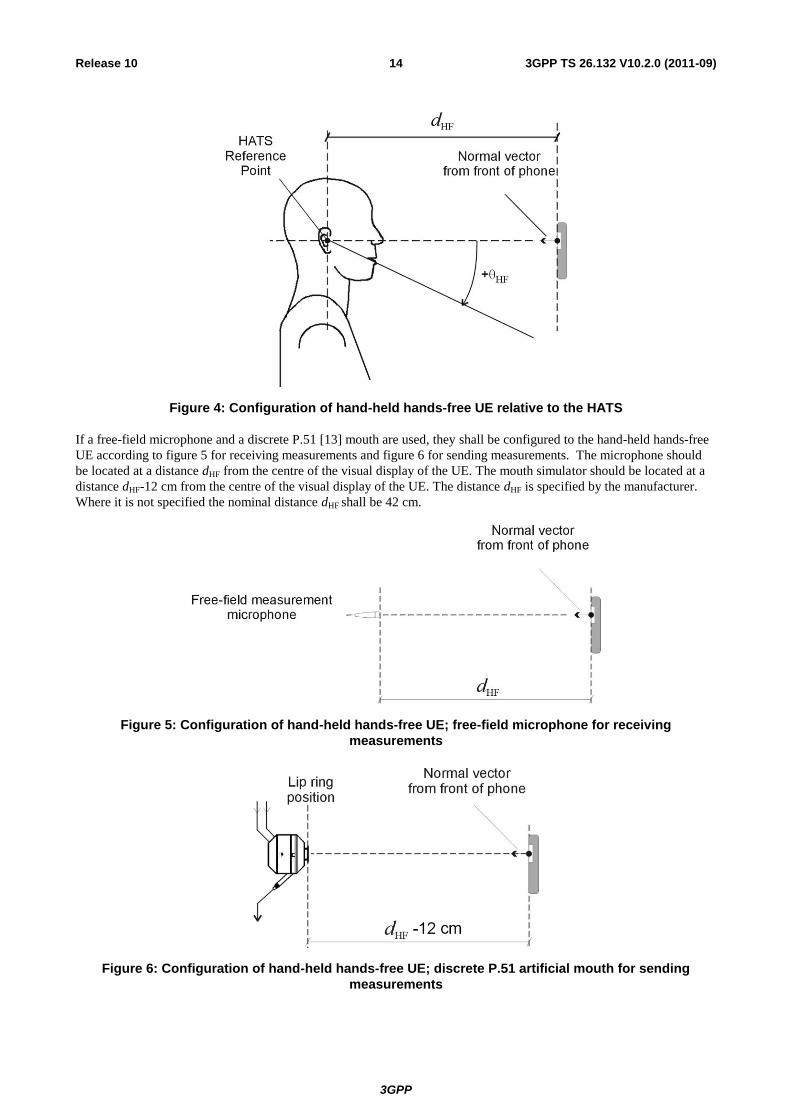
5.1.3.3 Hand-held hands-free
Either HATS or a free-field microphone with a discrete P.51 [13] artificial mouth may be used to measure a hand-held
hands-free type UE.
If HATS measurement equipment is used, it shall be configured to the hand-held hands-free UE according to figure 4.
The HATS should be positioned so that the HATS Reference Point is at a distance dHF from the centre point of the
visual display of the Mobile Station. The distance dHF is specified by the manufacturer. A vertical angle HF may be
specified by the manufacturer. Where it is not specified, the nominal distance dHF shall be 42 cm and HF shall be 0º.
NOTE: The nominal distance of 42 cm corresponds to the distance between the HATS reference point and lip-
plane (12 cm) with an additional 30 cm giving a realistic figure as a reference usage of hand-held
terminals.
3GPP
3GPP TS 26.132 V10.2.0 (2011-09) 14 Release 10
Figure 4: Configuration of hand-held hands-free UE relative to the HATS
If a free-field microphone and a discrete P.51 [13] mouth are used, they shall be configured to the hand-held hands-free
UE according to figure 5 for receiving measurements and figure 6 for sending measurements. The microphone should
be located at a distance dHF from the centre of the visual display of the UE. The mouth simulator should be located at a
distance dHF-12 cm from the centre of the visual display of the UE. The distance dHF is specified by the manufacturer.
Where it is not specified the nominal distance dHF shall be 42 cm.
Figure 5: Configuration of hand-held hands-free UE; free-field microphone for receiving
measurements
Figure 6: Configuration of hand-held hands-free UE; discrete P.51 artificial mouth for sending
measurements
3GPP
3GPP TS 26.132 V10.2.0 (2011-09) 15 Release 10
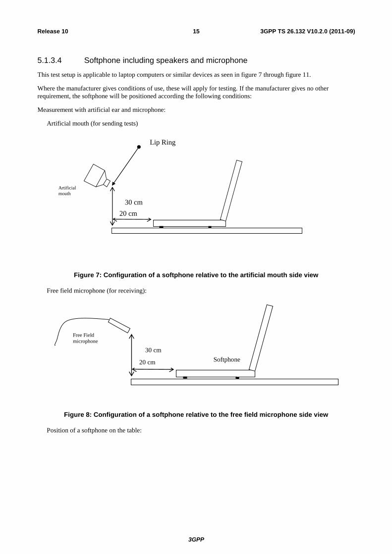
5.1.3.4 Softphone including speakers and microphone
This test setup is applicable to laptop computers or similar devices as seen in figure 7 through figure 11.
Where the manufacturer gives conditions of use, these will apply for testing. If the manufacturer gives no other
requirement, the softphone will be positioned according the following conditions:
Measurement with artificial ear and microphone:
Artificial mouth (for sending tests)
20 cm
Lip Ring
30 cm
40 cm
Artificial
mouth
Figure 7: Configuration of a softphone relative to the artificial mouth side view
Free field microphone (for receiving):
20 cm
30 cm
Softphone
Free Field
microphone
Figure 8: Configuration of a softphone relative to the free field microphone side view
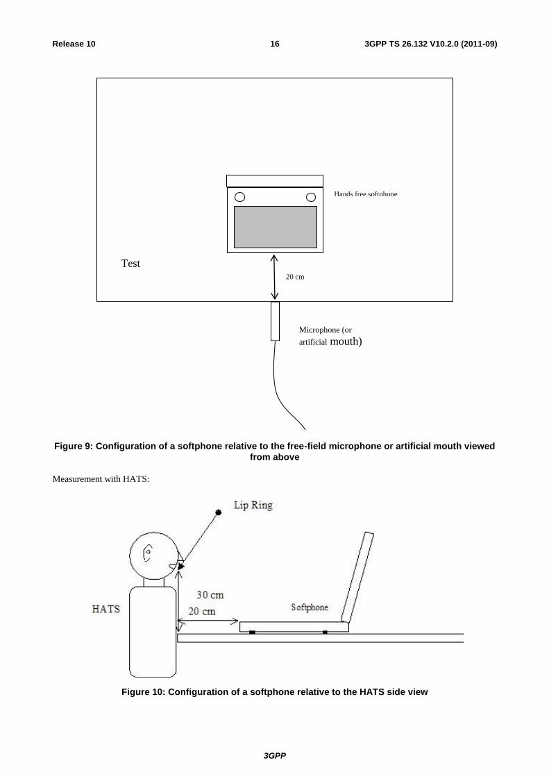
Position of a softphone on the table:
3GPP
3GPP TS 26.132 V10.2.0 (2011-09) 16 Release 10
20 cm
Test
table
Hands free softphone
Microphone (or
artificial mouth)
Figure 9: Configuration of a softphone relative to the free-field microphone or artificial mouth viewed
from above
Measurement with HATS:
Figure 10: Configuration of a softphone relative to the HATS side view
3GPP
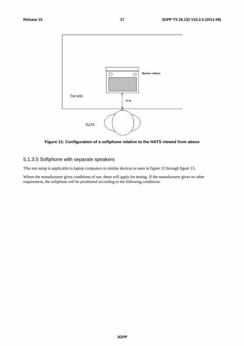
3GPP TS 26.132 V10.2.0 (2011-09) 17 Release 10
Figure 11: Configuration of a softphone relative to the HATS viewed from above
5.1.3.5 Softphone with separate speakers
This test setup is applicable to laptop computers or similar devices as seen in figure 12 through figure 15.
Where the manufacturer gives conditions of use, these will apply for testing. If the manufacturer gives no other
requirement, the softphone will be positioned according to the following conditions:
3GPP
3GPP TS 26.132 V10.2.0 (2011-09) 18 Release 10
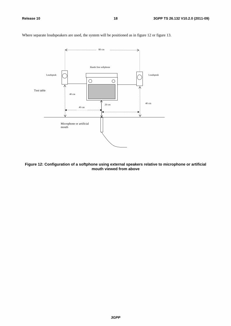
Where separate loudspeakers are used, the system will be positioned as in figure 12 or figure 13.
20 cm
Test table
Hands free softphone
Microphone or artificial
mouth
40 cm
40 cm
80 cm
Loudspeaker
Loudspeaker
40 cm
Figure 12: Configuration of a softphone using external speakers relative to microphone or artificial
mouth viewed from above
3GPP
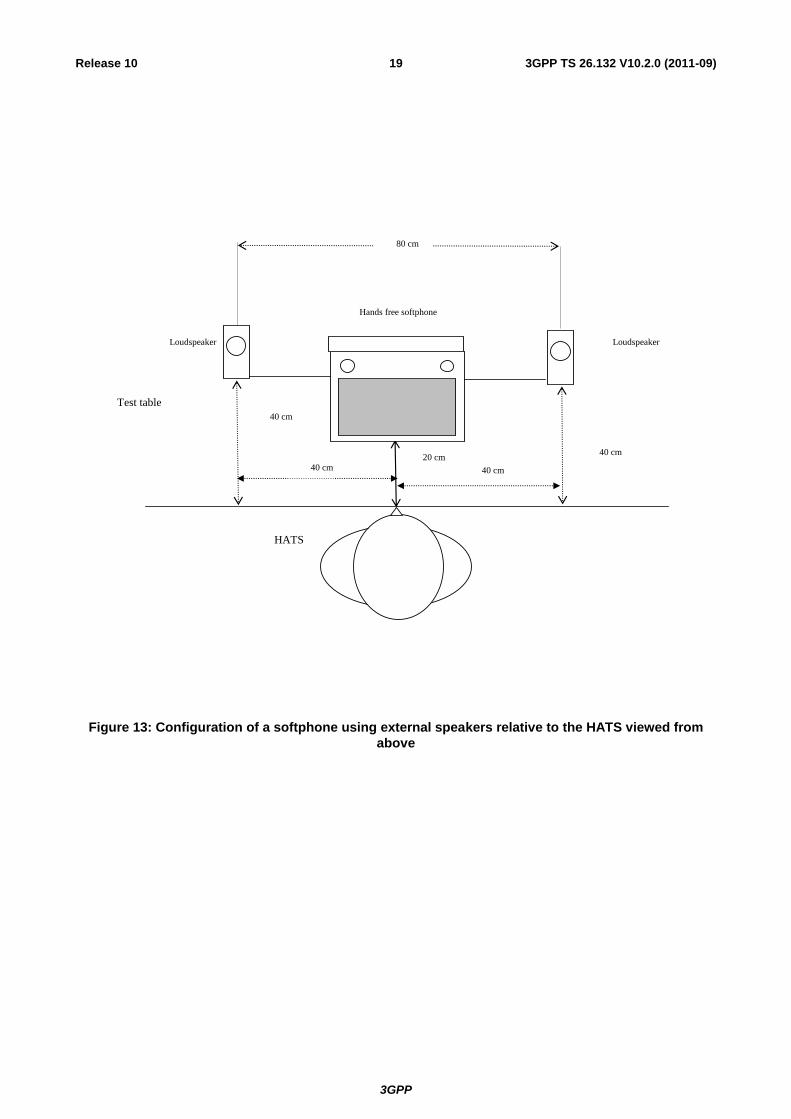
3GPP TS 26.132 V10.2.0 (2011-09) 19 Release 10
20 cm
Test table
Hands free softphone
HATS
40 cm
40 cm
80 cm
Loudspeaker
Loudspeaker
40 cm 40 cm
Figure 13: Configuration of a softphone using external speakers relative to the HATS viewed from
above
3GPP
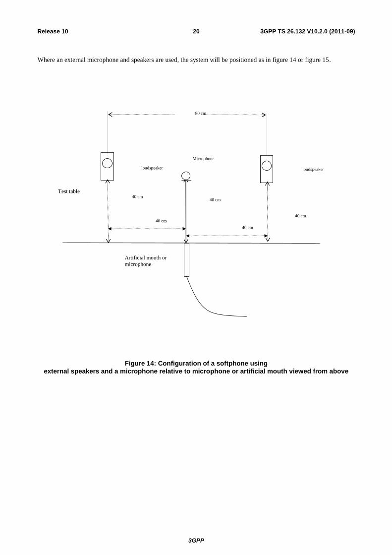
3GPP TS 26.132 V10.2.0 (2011-09) 20 Release 10
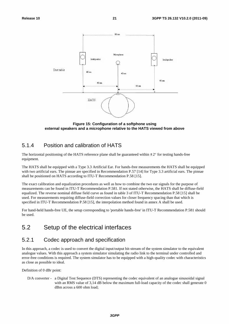
Where an external microphone and speakers are used, the system will be positioned as in figure 14 or figure 15.
40 cm
Test table
Microphone
Artificial mouth or
microphone
40 cm
40 cm
80 cm
loudspeaker loudspeaker
40 cm
40 cm
Figure 14: Configuration of a softphone using
external speakers and a microphone relative to microphone or artificial mouth viewed from above
3GPP
3GPP TS 26.132 V10.2.0 (2011-09) 21 Release 10
Figure 15: Configuration of a softphone using
external speakers and a microphone relative to the HATS viewed from above
5.1.4 Position and calibration of HATS
The horizontal positioning of the HATS reference plane shall be guaranteed within 2 for testing hands-free
equipment.
The HATS shall be equipped with a Type 3.3 Artificial Ear. For hands-free measurements the HATS shall be equipped
with two artificial ears. The pinnae are specified in Recommendation P.57 [14] for Type 3.3 artificial ears. The pinnae
shall be positioned on HATS according to ITU-T Recommendation P.58 [15].
The exact calibration and equalization procedures as well as how to combine the two ear signals for the purpose of
measurements can be found in ITU-T Recommendation P.581. If not stated otherwise, the HATS shall be diffuse-field
equalized. The reverse nominal diffuse field curve as found in table 3 of ITU-T Recommendation P.58 [15] shall be
used. For measurements requiring diffuse-field correction values for closer frequency spacing than that which is
specified in ITU-T Recommendation P.58 [15], the interpolation method found in annex A shall be used.
For hand-held hands-free UE, the setup corresponding to 'portable hands-free' in ITU-T Recommendation P.581 should
be used.
5.2 Setup of the electrical interfaces
5.2.1 Codec approach and specification
In this approach, a codec is used to convert the digital input/output bit-stream of the system simulator to the equivalent
analogue values. With this approach a system simulator simulating the radio link to the terminal under controlled and
error-free conditions is required. The system simulator has to be equipped with a high-quality codec with characteristics
as close as possible to ideal.
Definition of 0 dBr point:
D/A converter - a Digital Test Sequence (DTS) representing the codec equivalent of an analogue sinusoidal signal
with an RMS value of 3,14 dB below the maximum full-load capacity of the codec shall generate 0
dBm across a 600 ohm load;
3GPP
3GPP TS 26.132 V10.2.0 (2011-09) 22 Release 10
A/D converter - a 0 dBm signal generated from a 600 ohm source shall give the digital test sequence (DTS)
representing the codec equivalent of an analogue sinusoidal signal with an RMS value of 3,14 dB
below the maximum full-load capacity of the codec.
Narrowband telephony testing
For testing of a GSM or 3G terminal supporting narrowband telephony, the system simulator shall use the AMR speech
codec as defined in the 3GPP TS 26 series of specifications, at the source coding bit-rate of 12,2 kbit/s.
Wideband telephony testing
For testing of a GSM or 3G terminal supporting wideband telephony, the system simulator shall use the AMR-WB
speech codec as defined in 3GPP TS 26 series of specifications, at the source coding bit-rate of 12,65 kbit/s.
5.2.2 Direct digital processing approach
In this approach, the digital input/output bit-stream of the terminal connected through the radio link to the system
simulator is operated upon directly.
Narrowband telephony testing
For testing of a GSM or 3G terminal supporting narrowband telephony, the system simulator shall use the AMR speech
codec as defined in the 3GPP TS 26 series of specifications, at the source coding bit-rate of 12,2 kbit/s.
Wideband telephony testing
For testing of a GSM or 3G terminal supporting wideband telephony, the system simulator shall use the AMR-WB
speech codec as defined in the 3GPP TS 26 series of specifications, at the source coding bit rate of 12,65 kbit/s.
5.3 Accuracy of test equipment
Unless specified otherwise, the accuracy of measurements made by test equipment shall exceed the requirements defined
in table 1a.
Table 1a: Test equipment measurement accuracy
Item Accuracy
Electrical Signal Power ± 0,2 dB for levels -50 dBm
± 0,4 dB for levels < -50 dBm
Sound pressure ± 0,7 dB
Time ± 5%
Frequency ± 0,2%
3GPP
3GPP TS 26.132 V10.2.0 (2011-09) 23 Release 10
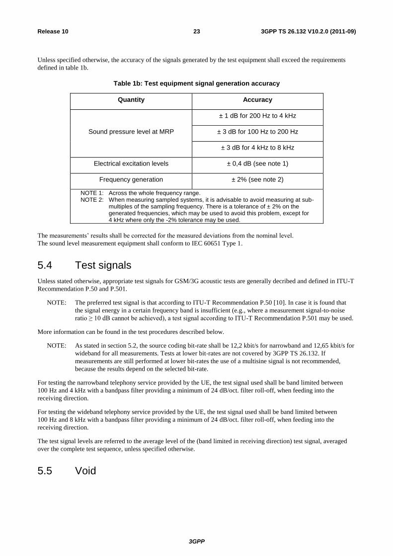
Unless specified otherwise, the accuracy of the signals generated by the test equipment shall exceed the requirements
defined in table 1b.
Table 1b: Test equipment signal generation accuracy
Quantity Accuracy
Sound pressure level at MRP
± 1 dB for 200 Hz to 4 kHz
± 3 dB for 100 Hz to 200 Hz
± 3 dB for 4 kHz to 8 kHz
Electrical excitation levels ± 0,4 dB (see note 1)
Frequency generation ± 2% (see note 2)
NOTE 1: Across the whole frequency range. NOTE 2: When measuring sampled systems, it is advisable to avoid measuring at sub-
multiples of the sampling frequency. There is a tolerance of ± 2% on the generated frequencies, which may be used to avoid this problem, except for 4 kHz where only the -2% tolerance may be used.
The measurements‟ results shall be corrected for the measured deviations from the nominal level.
The sound level measurement equipment shall conform to IEC 60651 Type 1.
5.4 Test signals
Unless stated otherwise, appropriate test signals for GSM/3G acoustic tests are generally decribed and defined in ITU-T
Recommendation P.50 and P.501.
NOTE: The preferred test signal is that according to ITU-T Recommendation P.50 [10]. In case it is found that
the signal energy in a certain frequency band is insufficient (e.g., where a measurement signal-to-noise
ratio ≥ 10 dB cannot be achieved), a test signal according to ITU-T Recommendation P.501 may be used.
More information can be found in the test procedures described below.
NOTE: As stated in section 5.2, the source coding bit-rate shall be 12,2 kbit/s for narrowband and 12,65 kbit/s for
wideband for all measurements. Tests at lower bit-rates are not covered by 3GPP TS 26.132. If
measurements are still performed at lower bit-rates the use of a multisine signal is not recommended,
because the results depend on the selected bit-rate.
For testing the narrowband telephony service provided by the UE, the test signal used shall be band limited between
100 Hz and 4 kHz with a bandpass filter providing a minimum of 24 dB/oct. filter roll-off, when feeding into the
receiving direction.
For testing the wideband telephony service provided by the UE, the test signal used shall be band limited between
100 Hz and 8 kHz with a bandpass filter providing a minimum of 24 dB/oct. filter roll-off, when feeding into the
receiving direction.
The test signal levels are referred to the average level of the (band limited in receiving direction) test signal, averaged
over the complete test sequence, unless specified otherwise.
5.5 Void
3GPP
3GPP TS 26.132 V10.2.0 (2011-09) 24 Release 10
5.5.1 Void
5.5.2 Void
6 Test conditions
6.1 Environmental conditions
6.1.1 Handset and headset terminals
For handset and headset measurements the test room shall be practically free-field down to a lowest frequency of
275 Hz; the handset or headset, including the HATS, shall be totally within this free-field volume. This shall be met if
deviations of the ideal free-field conditions are less than ± 1 dB. Qualification of the test room may be performed using
the method described in either ISO 3745 Annex A, or ITU-T P. 340 §5.4.
Alternatively, a test room may be used which meets the following two criteria:
1. The relationship between the pressure at the mouth opening and that at 5,0 cm, 7,5 cm and 10 cm in front of the
centre of the lip ring is within ± 0.5 dB of that which exists in a known acoustic free-field.
2. The relationship between the pressure at the mouth opening and that at the Ear canal Entrance Point (EEP) at
both the left and right ears of the HATS does not differ by more than ± 1 dB from that which exists in a known
free-field.
The ambient noise level shall be less than -30 dBPa(A); for idle channel noise measurements the ambient noise level
shall be less than –64dBPa(A).
Echo measurements shall be conducted in realistic rooms with an ambient noise level ≤ -64 dBPa(A).
6.1.2 Hands-free terminals
Hands-free terminals should generally be tested in their typical environment of application. Care must be taken that, e.g.,
noise levels are sufficiently low in order not to interfere with the measurements.
For desktop hands-free terminals the appropriate requirements shall be taken from ITU-T Recommendation P.340.
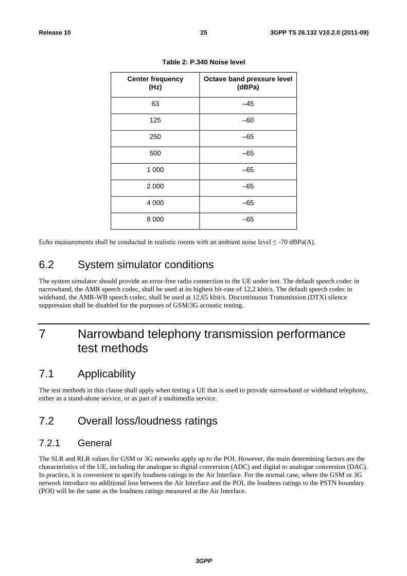
The broadband noise level shall not exceed –70 dBPa(A). The octave band noise level shall not exceed the values
specified in Table 2.
3GPP
3GPP TS 26.132 V10.2.0 (2011-09) 25 Release 10
Table 2: P.340 Noise level
Center frequency
(Hz)
Octave band pressure level
(dBPa)
63 –45
125 –60
250 –65
500 –65
1 000 –65
2 000 –65
4 000 –65
8 000 –65
Echo measurements shall be conducted in realistic rooms with an ambient noise level ≤ -70 dBPa(A).
6.2 System simulator conditions
The system simulator should provide an error-free radio connection to the UE under test. The default speech codec in
narrowband, the AMR speech codec, shall be used at its highest bit-rate of 12,2 kbit/s. The default speech codec in
wideband, the AMR-WB speech codec, shall be used at 12,65 kbit/s. Discontinuous Transmission (DTX) silence
suppression shall be disabled for the purposes of GSM/3G acoustic testing.
7 Narrowband telephony transmission performance test methods
7.1 Applicability
The test methods in this clause shall apply when testing a UE that is used to provide narrowband or wideband telephony,
either as a stand-alone service, or as part of a multimedia service.
7.2 Overall loss/loudness ratings
7.2.1 General
The SLR and RLR values for GSM or 3G networks apply up to the POI. However, the main determining factors are the
characteristics of the UE, including the analogue to digital conversion (ADC) and digital to analogue conversion (DAC).
In practice, it is convenient to specify loudness ratings to the Air Interface. For the normal case, where the GSM or 3G
network introduce no additional loss between the Air Interface and the POI, the loudness ratings to the PSTN boundary
(POI) will be the same as the loudness ratings measured at the Air Interface.
3GPP
3GPP TS 26.132 V10.2.0 (2011-09) 26 Release 10
7.2.2 Connections with handset UE
7.2.2.1 Sending loudness rating (SLR)
a) The test signal to be used for normative measurements shall be the artificial voice according to ITU-T
Recommendation P.50 [10]. Alternatively, a speech-like test signal as described in ITU-T Recommendation
P.501 may be used. The type of test signal used shall be stated in the test report. The spectrum of the acoustic
signal produced by the artificial mouth is calibrated under free-field conditions at the MRP. The test signal level
shall be -4,7 dBPa measured at the MRP. The test signal level is averaged over the complete test signal sequence.
b) The handset terminal is setup as described in clause 5. The sending sensitivity shall be calculated from each band
of the 14 frequencies given in table 1 of ITU-T Recommendation P.79 [16], bands 4 to 17. For the calculation,
the averaged measured level at the electrical reference point for each frequency band is referred to the averaged
test signal level measured in each frequency band at the MRP.
c) The sensitivity is expressed in terms of dBV/Pa and the SLR shall be calculated according to ITU-T
Recommendation P.79 [16], formula (A-23b), over bands 4 to 17, using m = 0,175 and the sending weighting
factors from ITU-T Recommendation P.79 [16], table 1.
7.2.2.2 Receiving loudness rating (RLR)
a) The test signal to be used for normative measurements shall be the artificial voice according to ITU-T
Recommendation P.50 [10]. Alternatively a speech-like test signal as described in ITU-T Recommendation P.501
may be used. The type of test signal used shall be stated in the test report. The test signal level shall be -16 dBm0
measured at the digital reference point or the equivalent analogue point. The test signal level is averaged over the
complete test signal sequence.
b) The handset terminal is setup as described in clause 5. The receiving sensitivity shall be calculated from each
band of the 14 frequencies given in table 1 of ITU-T Recommendation P.79 [16], bands 4 to 17. For the
calculation, the averaged measured level at each frequency band is referred to the averaged test signal level
measured in each frequency band.
c) The sensitivity is expressed in terms of dBPa/V and the RLR shall be calculated according to ITU-T
Recommendation P.79 [16], formula (A-23c), over bands 4 to 17, using m = 0,175 and the receiving weighting
factors from table 1 of ITU-T Recommendation P.79 [16].
d) DRP-ERP correction is used. No leakage correction shall be applied.
7.2.3 Connections with desktop and vehicle-mounted hands-free UE
Vehicle-mounted hands-free UE should be tested within the vehicle (for totally integrated vehicle hands-free systems) or
in a vehicle simulator, as described in 3GPP TS 03.58 [11].
Free-field measurements for vehicle-mounted hands-free are for further study.
7.2.3.1 Sending loudness rating (SLR)
a) The test signal to be used for normative measurements shall be the artificial voice according to ITU-T
Recommendation P.50 [10]. Alternatively, a speech-like test signal as described in ITU-T Recommendation
P.501 may be used. The type of test signal used shall be stated in the test report. The spectrum of the acoustic
signal produced by the artificial mouth is calibrated under free-field conditions at the MRP. The test signal level
shall be –4,7 dBPa measured at the MRP. The test signal level is averaged over the complete test signal
sequence. The broadband signal level is then adjusted to –28,7 dBPa at the HFRP or the HATS HFRP (as
defined in ITU-Recommendation P.581) and the spectrum is not altered.
The spectrum at the MRP and the actual level at the MRP (measured in 1/3-octaves) are used as references to
determine the sending sensitivity SmJ.
3GPP
3GPP TS 26.132 V10.2.0 (2011-09) 27 Release 10
b) The hands-free terminal is setup as described in clause 5. The sending sensitivity shall be calculated from each
band of the 14 frequencies given in table 1 of ITU-T Recommendation P.79 [16], bands 4 to 17. For the
calculation, the averaged measured level at the electrical reference point for each frequency band is referred to
the averaged test signal level measured in each frequency band at the MRP.
c) The sensitivity is expressed in terms of dBV/Pa and the SLR shall be calculated according to ITU-T
Recommendation P.79 [16], formula (A-23b), over bands 4 to 17, using m = 0,175 and the sending weighting
factors from ITU-T Recommendation P.79 [16], table 1.
7.2.3.2 Receiving Loudness Rating (RLR)
a) The test signal to be used for normative measurements shall be the artificial voice according to ITU-T
Recommendation P.50 [10]. Alternatively, a speech-like test signal as described in ITU-T Recommendation
P.501 may be used. The type of test signal used shall be stated in the test report. The test signal level shall be -16
dBm0 measured at the digital reference point or the equivalent analogue point. The test signal level is averaged
over the complete test signal sequence.
b) The hands-free terminal is setup as described in clause 5. If a HATS is used, then it is free-field equalized as
described in ITU-T Recommendation P.581. The equalized output signal of each artificial ear is power-averaged
over the total duration of the analysis; the right and left artificial ear signals are voltage-summed for each 1/3-
octave frequency band; these 1/3-octave band data are considered as the input signal to be used for calculations
or measurements. The receiving sensitivity shall be calculated from each band of the 14 frequencies given in
table 1 of ITU-T Recommendation P.79 [16], bands 4 to 17.
For the calculation, the averaged measured level at each frequency band is referred to the averaged test signal
level measured in each frequency band.
c) The sensitivity is expressed in terms of dBPa/V and the RLR shall be calculated according to ITU-T
Recommendation P.79 [16], formula (A-23c), over bands 4 to 17, using m = 0,175 and the receiving weighting
factors from table 1 of ITU-T Recommendation P.79 [16].
d) No leakage correction shall be applied. The hands-free correction, as described in ITU-T Recommendation P.340
shall be applied. To compute the receiving loudness rating (RLR) for a hands-free terminal (see also ITU-T
Recommendation P.340), when using the combination of left and right artificial ear signals from the HATS, the
HFLE has to be 8 dB instead of 14 dB. For further information see ITU-T Recommendation P.581.
7.2.4 Connections with hand-held hands-free UE
7.2.4.1 Sending loudness rating (SLR)
a) The test signal to be used for normative measurements shall be the artificial voice according to ITU-T
Recommendation P.50 [10]. Alternatively, a speech-like test signal as described in ITU-T Recommendation
P.501 may be used. The type of test signal used shall be stated in the test report. The spectrum of the acoustic
signal produced by the artificial mouth is calibrated under free-field conditions at the MRP. The test signal level
shall be –4,7 dBPa measured at the MRP. The test signal level is averaged over the complete test signal
sequence. The broadband signal level is then adjusted to –28,7 dBPa at the HFRP or the HATS HFRP (as
defined in ITU-T Recommendation P.581) and the spectrum is not altered.
The spectrum at the MRP and the actual level at the MRP (measured in 1/3-octaves) are used as references to
determine the sending sensitivity SmJ.
b) The hands-free terminal is setup as described in clause 5. The sending sensitivity shall be calculated from each
band of the 14 frequencies given in table 1 of ITU-T Recommendation P.79 [16], bands 4 to 17. For the
calculation, the averaged measured level at the electrical reference point for each frequency band is referred to
the averaged test signal level measured in each frequency band at the MRP.
c) The sensitivity is expressed in terms of dBV/Pa and the SLR shall be calculated according to ITU-T
Recommendation P.79 [16], formula (A-23b), over bands 4 to 17, using m = 0,175 and the sending weighting
factors from ITU-T Recommendation P.79 [16], table 1.
3GPP
3GPP TS 26.132 V10.2.0 (2011-09) 28 Release 10
7.2.4.2 Receiving loudness rating (RLR)
a) The test signal to be used for normative measurements shall be the artificial voice according to ITU-T
Recommendation P.50 [10]. Alternatively, a speech-like test signal as described in ITU-T Recommendation
P.501 may be used. The type of test signal used shall be stated in the test report. The test signal level shall be -16
dBm0 measured at the digital reference point or the equivalent analogue point. The test signal level is averaged
over the complete test signal sequence.
b) The hands-free terminal is setup as described in clause 5. If a HATS is used, then it is free-field equalized as
described in ITU-T Recommendation P.581. The equalized output signal of each artificial ear is power-averaged
over the total duration of the analysis; the right and left artificial ear signals are voltage-summed for each 1/3-
octave frequency band; these 1/3-octave band data are considered as the input signal to be used for calculations
or measurements. The receiving sensitivity shall be calculated from each band of the 14 frequencies given in
table 1 of ITU-T Recommendation P.79 [16], bands 4 to 17.
For the calculation, the averaged measured level at each frequency band is referred to the averaged test signal
level measured in each frequency band.
c) The sensitivity is expressed in terms of dBPa/V and the RLR shall be calculated according to ITU-T
Recommendation P.79 [16], formula (A-23c), over bands 4 to 17, using m = 0,175 and the receiving weighting
factors from table 1 of ITU-T Recommendation P.79 [16].
d) No leakage correction shall be applied. The hands-free correction as described in ITU-T Recommendation P.340
shall be applied. To compute the receiving loudness rating (RLR) for hands-free terminals (see also ITU-T
Recommendation P.340), when using the combination of left and right artificial ear signals from the HATS, the
HFLE has to be 8 dB instead of 14 dB. For further information see ITU-T Recommendation P.581.
7.2.5 Connections with headset UE
Same as for handset.
7.3 Idle channel noise (handset and headset UE)
For idle noise measurements in sending and receiving directions, care should be taken that only the noise is windowed
out by the analysis and the result is not impaired by any remaining reverberation or by noise and/or interference from
various other sources. Some examples are air-conducted or vibration-conducted noise from sources inside or outside the
test chamber, disturbances from lights and regulators, mains supply induced noise including grounding issues, test
system and system simulator inherent noise as well as radio interference from the UE to test equipment such as ear
simulators, microphone amplifiers, etc.
7.3.1 Sending
The terminal should be configured to the test equipment as described in subclause 5.1.
The environment shall comply with the conditions described in subclause 6.1.
The noise level at the output of the SS is measured with psophometric weighting. The psophometric weighting filter is
described in ITU-T Recommendation O.41.
A test signal may have to be intermittently applied to prevent „silent mode‟ operation of the MS. This is for further
study.
The measured part of the noise shall be 170,667 ms (which equals 8192 samples in a 48 kHz sample rate test system).
The spectral distribution of the noise is analyzed with an 8k FFT using windowing with ≤ 0,1 dB leakage for non bin-
centered signals. This can be achieved with a window function commonly known as a “flat top window”. Within the
specified frequency range, the FFT bin that has the highest level is searched for; the level of this bin is the maximum
level of a single frequency disturbance.
To improve repeatability, the test sequence (optional activation followed by the noise level measurement) may be
contiguously repeated one or more times.
3GPP
3GPP TS 26.132 V10.2.0 (2011-09) 29 Release 10
The total noise powers obtained from such repeats shall be averaged. The total result shall be 10 * log10 of this average
in dB.
The single frequency maximum powers obtained from such repeats shall be averaged. The total result shall be 10*log10
of this average in dB.
7.3.2 Receiving
The terminal should be configured to the test equipment as described in subclause 5.1.
The environment shall comply with the conditions described in subclause 6.1.
A test signal may have to be intermittently applied to prevent „silent mode‟ operation of the MS. This is for further
study.
The noise level shall be measured with A-weighting at the DRP with diffuse-field correction. The A-weighting filter is
described in IEC 60651.
The measured part of the noise shall be 170,667 ms (which equals 8192 samples in a 48 kHz sample rate test system).
The spectral distribution of the noise is analyzed with an 8k FFT using windowing with ≤ 0.1 dB leakage for non bin-
centred signals. This can be achieved with a window function commonly known as a “flat top window”. Within the
specified frequency range, the FFT bin that has the highest level is searched for; the level of this bin is the maximum
level of a single frequency disturbance.
To improve repeatability, considering the test sequence (optional activation followed by the noise level measurement)
may be contiguously repeated one or more times.
The total noise powers obtained from such repeats shall be averaged. The total result shall be 10*log10 of this average in
dB.
The single frequency maximum powers obtained from such repeats shall be averaged. The total result shall be 10*log10
of this average in dB.
7.4 Sensitivity/frequency characteristics
7.4.1 Handset and headset UE sending
a) The test signal to be used for normative measurements shall be the artificial voice according to ITU-T
Recommendation P. 50 [10]. Alternatively, a speech-like test signal as described in ITU-T Recommendation
P.501 may be used. The type of test signal used shall be stated in the test report. The spectrum of the acoustic
signal produced by the artificial mouth is calibrated under free-field conditions at the MRP. The test signal level
shall be –4,7 dBPa measured at the MRP. The test signal level is averaged over the complete test signal
sequence.
b) The handset terminal is setup as described in clause 5. Measurements shall be made at 1/12-octave intervals as
given by the R.40 series of preferred numbers in ISO 3 for frequencies from 100 Hz to 4 kHz inclusive. For the
calculation, the averaged measured level at the electrical reference point for each frequency band is referred to
the averaged test signal level measured in each frequency band at the MRP.
c) The sensitivity is expressed in terms of dBV/Pa.
7.4.2 Handset and headset UE receiving
a) The test signal to be used for normative measurements shall be the artificial voice according to ITU-T
Recommendation P.50 [10]. Alternatively, a speech-like test signal as described in ITU-T Recommendation
P.501 may be used. The type of test signal used shall be stated in the test report. The test signal level shall be -16
dBm0 measured at the digital reference point or the equivalent analogue point. The test signal level is averaged
over the complete test signal sequence.
3GPP
3GPP TS 26.132 V10.2.0 (2011-09) 30 Release 10
b) The handset terminal is setup as described in clause 5. Measurements shall be made at 1/12-octave intervals as
given by the R.40 series of preferred numbers in ISO 3 for frequencies from 100 Hz to 4 kHz inclusive. For the
calculation, the averaged measured level at each frequency band is referred to the averaged test signal level
measured in each frequency band.
c) The HATS is diffuse-field equalized. The sensitivity is expressed in terms of dBPa/V. Information about
correction factors is available in ITU-T Recommendation P.57 [14].
Optionally, the measurements may be repeated with 2 N and 13 N application force. For these test cases no normative
values apply.
7.4.3 Desktop and vehicle-mounted hands-free UE sending
a) The test signal to be used for normative measurements shall be the artificial voice according to ITU-T
Recommendation P.50 [10]. Alternatively, a speech-like test signal as described in ITU-T Recommendation
P.501 may be used. The type of test signal used shall be stated in the test report. The spectrum of the acoustic
signal produced by the artificial mouth is calibrated under free-field conditions at the MRP. The test signal level
shall be –4,7 dBPa measured at the MRP. The test signal level is averaged over the complete test signal
sequence. The broadband signal level is then adjusted to –28,7 dBPa at the HFRP or the HATS HFRP (as
defined in ITU-T Recommendation P.581) and the spectrum is not altered.
The spectrum at the MRP and the actual level at the MRP (measured in 1/3-octaves) are used as references to
determine the sending sensitivity SmJ.
b) The hands-free terminal is setup as described in clause 5. Measurements shall be made at 1/3-octave intervals as
given by the R.40 series of preferred numbers in ISO 3 for frequencies from 100 Hz to 4 kHz inclusive. For the
calculation, the averaged measured level at each frequency band is referred to the averaged test signal level
measured in each frequency band.
c) The sensitivity is expressed in terms of dBV/Pa.
7.4.4 Desktop and vehicle-mounted hands-free UE receiving
a) The test signal to be used for normative measurements shall be the artificial voice according to ITU-T
Recommendation P. 50 [10]. Alternatively, a speech-like test signal as described in ITU-T Recommendation
P.501 may be used. The type of test signal used shall be stated in the test report. The test signal level shall be -16
dBm0 measured at the digital reference point or the equivalent analogue point. The test signal level is averaged
over the complete test signal sequence.
b) The hands-free terminal is setup as described in clause 5. If a HATS is used, then it is free-field equalized as
described in ITU-T Recommendation P.581. The equalized output signal of each artificial ear is power-averaged
over the total duration of the analysis; the right and left artificial ear signals are voltage-summed for each 1/3-
octave frequency band; these 1/3-octave band data are considered as the input signal to be used for calculations
or measurements. Measurements shall be made at 1/3-octave intervals as given by the R.40 series of preferred
numbers in ISO 3 for frequencies from 100 Hz to 4 kHz inclusive. For the calculation the averaged measured
level at each frequency band is referred to the averaged test signal level measured in each frequency band.
c) The sensitivity is expressed in terms of dBPa/V.
7.4.5 Hand-held hands-free UE sending
a) The test signal to be used for normative measurements shall be the artificial voice according to ITU-T
Recommendation P.50 [10]. Alternatively, a speech-like test signal as described in ITU-T Recommendation
P.501 may be used. The type of test signal used shall be stated in the test report. The spectrum of the acoustic
signal produced by the artificial mouth is calibrated under free-field conditions at the MRP. The test signal level
shall be –4,7 dBPa measured at the MRP. The test signal level is averaged over the complete test signal
sequence. The broadband signal level then is adjusted to –28,7 dBPa at the HFRP or the HATS HFRP (as
defined in ITU-T Recommendation P.581) and the spectrum is not altered.
3GPP
3GPP TS 26.132 V10.2.0 (2011-09) 31 Release 10
The spectrum at the MRP and the actual level at the MRP (measured in 1/3-octaves) are used as reference to
determine the sending sensitivity SmJ.
b) The hands-free terminal is setup as described in clause 5. Measurements shall be made at 1/3-octave intervals as
given by the R.40 series of preferred numbers in ISO 3 for frequencies from 100 Hz to 4 kHz inclusive. For the
calculation, the averaged measured level at each frequency band is referred to the averaged test signal level
measured in each frequency band.
c) The sensitivity is expressed in terms of dBV/Pa.
7.4.6 Hand-held hands-free UE receiving
a) The test signal to be used for normative measurements shall be the artificial voice according to ITU-T
Recommendation P.50 [10]. Alternatively, a speech-like test signal as described in ITU-T Recommendation
P.501 may be used. The type of test signal used shall be stated in the test report. The test signal level shall be -16
dBm0 measured at the digital reference point or the equivalent analogue point. The test signal level is averaged
over the complete test signal sequence.
b) The hands-free terminal is setup as described in clause 5. If a HATS is used, then it is free-field equalized as
described in ITU-T Recommendation P.581. The equalized output signal of each artificial ear is power-averaged
over the total duration of the analysis; the right and left artificial ear signals are voltage-summed for each 1/3-
octave band frequency band; these 1/3-octave band data are considered as the input signal to be used for
calculations or measurements. Measurements shall be made at 1/3-octave intervals as given by the R.40 series of
preferred numbers in ISO 3 for frequencies from 100 Hz to 4 kHz inclusive. For the calculation, the averaged
measured level at each frequency band is referred to the averaged test signal level measured in each frequency
band.
c) The sensitivity is expressed in terms of dBPa/V.
7.5 Sidetone characteristics
7.5.1 Connections with handset UE
The test signal to be used for normative measurements shall be the artificial voice according to ITU-T Recommendation
P.50 [10]. Alternatively, a speech-like test signal as described in ITU-T Recommendation P.501 may be used. The type
of test signal used shall be stated in the test report. The spectrum of the acoustic signal produced by the artificial mouth
is calibrated under free-field conditions at the MRP. The test signal level shall be –4,7 dBPa measured at the MRP. The
test signal level is averaged over the complete test signal sequence.
7.5.1.1 void
7.5.1.2 Connections with handset UE – HATS method
The handset UE is setup as described in clause 5. The application force shall be 13 N on the Type 3.3 artificial ear.
Where a user-operated volume control is provided, the measurements shall be carried out at the nominal setting of the
volume control. In addition, the measurement is repeated at the maximum volume control setting.
Measurements shall be made at 1/12-octave intervals as given by the R.40 series of preferred numbers in ISO 3 for
frequencies from 100 Hz to 8 kHz inclusive. For the calculation, the averaged measured level at each frequency band
(ITU-T Recommendation P.79 [16], table 4, bands 4 to 17) is referred to the averaged test signal level measured in each
frequency band.
The sidetone path loss (LmeST), as expressed in dB, and the Sidetone Masking Rating (STMR), expressed in dB, shall
be calculated from formula 5-1 of ITU-T Recommendation P.79 [16], using m = 0.225 and the weighting factors in
table B.2 (unsealed condition) of ITU-T Recommendation P.79 [16]. No leakage correction (LE) shall be applied. DRP-
ERP correction is used.
3GPP
3GPP TS 26.132 V10.2.0 (2011-09) 32 Release 10
7.5.2 Headset UE
The test signal to be used for normative measurements shall be the artificial voice according to ITU-T Recommendation
P. 50 [10]. Alternatively, a speech-like test signal as described in ITU-T Recommendation P.501 may be used. The type
of test signal used shall be stated in the test report. The spectrum of the acoustic signal produced by the artificial mouth
is calibrated under free-field conditions at the MRP. The test signal level shall be –4,7 dBPa measured at the MRP. The
test signal level is averaged over the complete test signal sequence.
Measurements shall be made at 1/12-octave intervals as given by the R.10 series of preferred numbers in ISO 3 for
frequencies from 100 Hz to 8 kHz inclusive. For the calculation, the averaged measured level at each frequency band
(ITU-T Recommendation P.79 [16], table 4, bands 4 to 17) is referred to the averaged test signal level measured in each
frequency band.
The sidetone path loss (LmeST), as expressed in dB, shall be calculated from each band of the 14 frequencies given in
table 1 of ITU-T Recommendation P.79 [16], bands 4 to 17. The STMR (in dB) shall be calculated from formula B-4 of
ITU-T Recommendation P.79 [16], using m = 0.225 and the weighting factors in table B.2 (unsealed condition) of ITU-
T Recommendation P.79 [16]. No leakage correction (LE) shall be applied. DRP-ERP correction is used.
7.5.3 Hands-free UE (all categories)
No requirement other than echo control.
7.6 Stability loss
Where a user-controlled volume control is provided it is set to maximum.
Handset UE: The handset is placed on a hard plane surface with the earpiece facing the surface.
Headset UE: The requirement applies for the closest possible position between microphone and headset receiver within
the intended wearing position.
NOTE: Depending on the type of headset it may be necessary to repeat the measurement in different positions.
Hands-free UE (all categories): No requirement other than echo loss.
Before the actual test a training sequence consisting of 10 s male artificial voice and 10 s female artificial voice
according to ITU-T Recommendation P.50 [10] is applied. The training sequence level shall be –16 dBm0 in order to
not overload the codec.
The test signal is a PN-sequence complying with ITU-T Recommendation P.501 with a length of 4 096 points (for a
48 kHz sampling rate system) and a crest factor of 6 dB instead of 11 dB. The duration of the test signal is 250 ms. With
an input signal of -3 dBm0, the attenuation from input to output of the system simulator shall be measured under the
following conditions:
a) The handset or the headset, with the transmission circuit fully active, shall be positioned on a hard plane surface
with at least 400 mm free space in all directions; the earpiece shall face towards the surface as shown in
figure 15c;
b) The headset microphone is positioned as close as possible to the receiver(s) within the intended wearing position;
c) For a binaural headset, the receivers are placed symmetrically around the microphone.
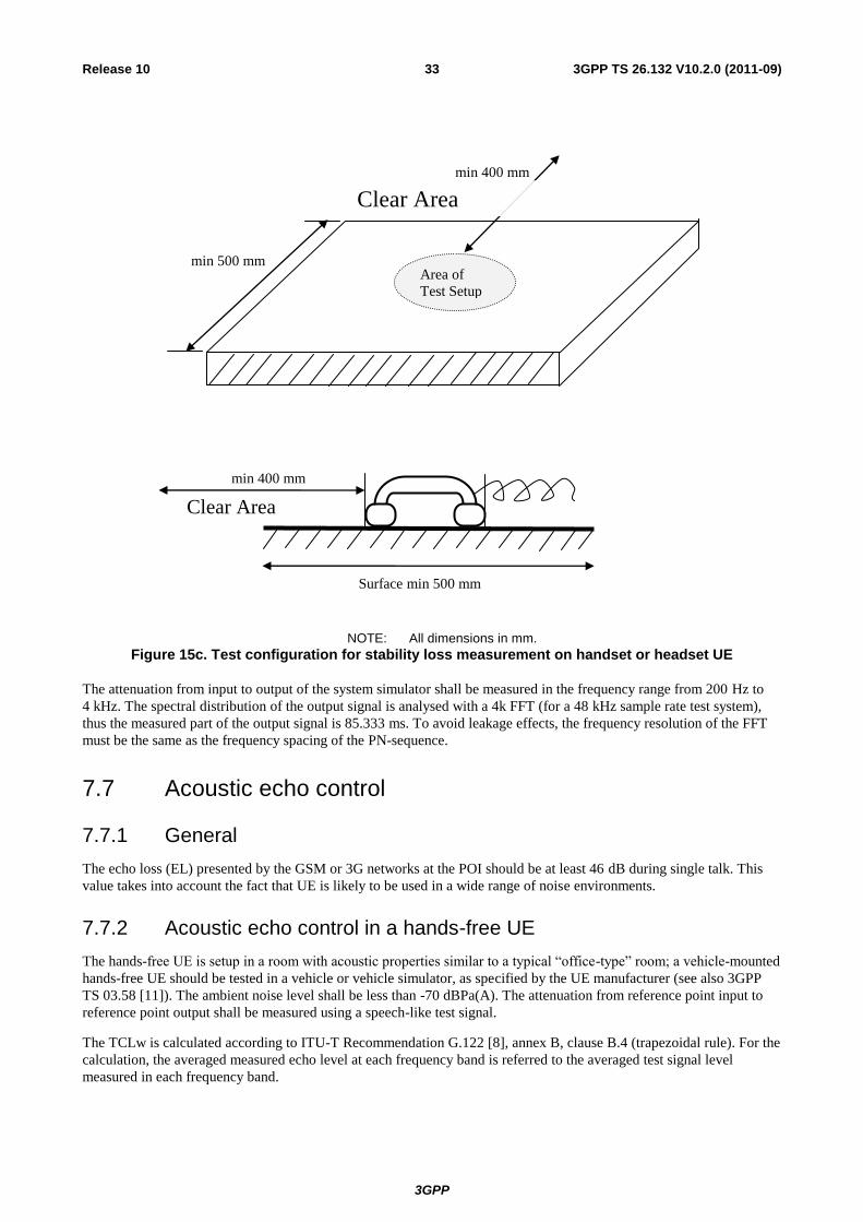
3GPP
3GPP TS 26.132 V10.2.0 (2011-09) 33 Release 10
Area of
Test Setup
min 500 mm
min 400 mm
Clear Area
min 400 mm
Clear Area
Surface min 500 mm
NOTE: All dimensions in mm.
Figure 15c. Test configuration for stability loss measurement on handset or headset UE
The attenuation from input to output of the system simulator shall be measured in the frequency range from 200 Hz to
4 kHz. The spectral distribution of the output signal is analysed with a 4k FFT (for a 48 kHz sample rate test system),
thus the measured part of the output signal is 85.333 ms. To avoid leakage effects, the frequency resolution of the FFT
must be the same as the frequency spacing of the PN-sequence.
7.7 Acoustic echo control
7.7.1 General
The echo loss (EL) presented by the GSM or 3G networks at the POI should be at least 46 dB during single talk. This
value takes into account the fact that UE is likely to be used in a wide range of noise environments.
7.7.2 Acoustic echo control in a hands-free UE
The hands-free UE is setup in a room with acoustic properties similar to a typical “office-type” room; a vehicle-mounted
hands-free UE should be tested in a vehicle or vehicle simulator, as specified by the UE manufacturer (see also 3GPP
TS 03.58 [11]). The ambient noise level shall be less than -70 dBPa(A). The attenuation from reference point input to
reference point output shall be measured using a speech-like test signal.
The TCLw is calculated according to ITU-T Recommendation G.122 [8], annex B, clause B.4 (trapezoidal rule). For the
calculation, the averaged measured echo level at each frequency band is referred to the averaged test signal level
measured in each frequency band.
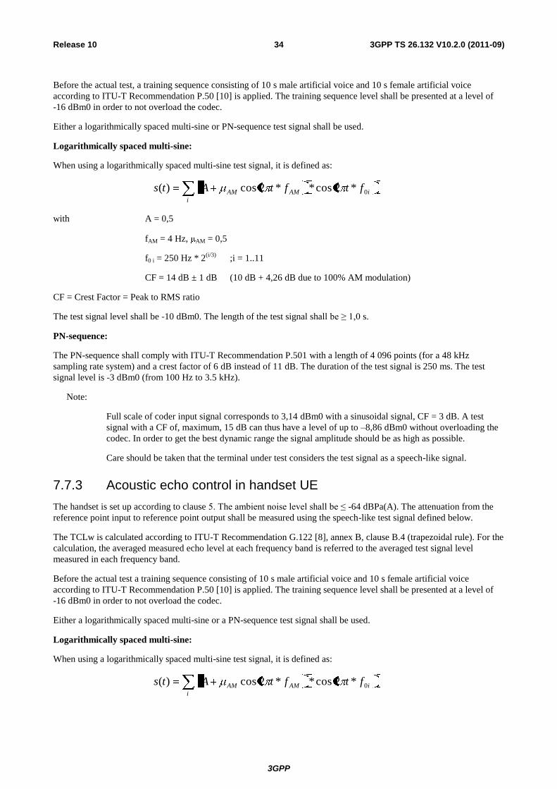
3GPP
3GPP TS 26.132 V10.2.0 (2011-09) 34 Release 10
Before the actual test, a training sequence consisting of 10 s male artificial voice and 10 s female artificial voice
according to ITU-T Recommendation P.50 [10] is applied. The training sequence level shall be presented at a level of
-16 dBm0 in order to not overload the codec.
Either a logarithmically spaced multi-sine or PN-sequence test signal shall be used.
Logarithmically spaced multi-sine:
When using a logarithmically spaced multi-sine test signal, it is defined as:
i
iAMAM ftftAts 0*2cos**2cos)(
with A = 0,5
fAM = 4 Hz, AM = 0,5
f0 i = 250 Hz * 2(i/3)
;i = 1..11
CF = 14 dB ± 1 dB (10 dB + 4,26 dB due to 100% AM modulation)
CF = Crest Factor = Peak to RMS ratio
The test signal level shall be -10 dBm0. The length of the test signal shall be ≥ 1,0 s.
PN-sequence:
The PN-sequence shall comply with ITU-T Recommendation P.501 with a length of 4 096 points (for a 48 kHz
sampling rate system) and a crest factor of 6 dB instead of 11 dB. The duration of the test signal is 250 ms. The test
signal level is -3 dBm0 (from 100 Hz to 3.5 kHz).
Note:
Full scale of coder input signal corresponds to 3,14 dBm0 with a sinusoidal signal, CF = 3 dB. A test
signal with a CF of, maximum, 15 dB can thus have a level of up to –8,86 dBm0 without overloading the
codec. In order to get the best dynamic range the signal amplitude should be as high as possible.
Care should be taken that the terminal under test considers the test signal as a speech-like signal.
7.7.3 Acoustic echo control in handset UE
The handset is set up according to clause 5. The ambient noise level shall be ≤ -64 dBPa(A). The attenuation from the
reference point input to reference point output shall be measured using the speech-like test signal defined below.
The TCLw is calculated according to ITU-T Recommendation G.122 [8], annex B, clause B.4 (trapezoidal rule). For the
calculation, the averaged measured echo level at each frequency band is referred to the averaged test signal level
measured in each frequency band.
Before the actual test a training sequence consisting of 10 s male artificial voice and 10 s female artificial voice
according to ITU-T Recommendation P.50 [10] is applied. The training sequence level shall be presented at a level of
-16 dBm0 in order to not overload the codec.
Either a logarithmically spaced multi-sine or a PN-sequence test signal shall be used.
Logarithmically spaced multi-sine:
When using a logarithmically spaced multi-sine test signal, it is defined as:
i
iAMAM ftftAts 0*2cos**2cos)(
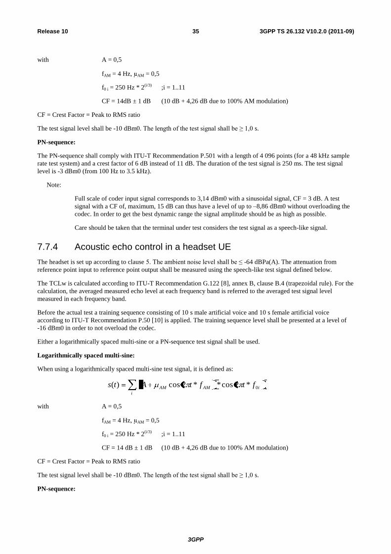
3GPP
3GPP TS 26.132 V10.2.0 (2011-09) 35 Release 10
with A = 0,5
fAM = 4 Hz, AM = 0,5
f0 i = 250 Hz * 2(i/3)
;i = 1..11
CF = 14dB ± 1 dB (10 dB + 4,26 dB due to 100% AM modulation)
CF = Crest Factor = Peak to RMS ratio
The test signal level shall be -10 dBm0. The length of the test signal shall be ≥ 1,0 s.
PN-sequence:
The PN-sequence shall comply with ITU-T Recommendation P.501 with a length of 4 096 points (for a 48 kHz sample
rate test system) and a crest factor of 6 dB instead of 11 dB. The duration of the test signal is 250 ms. The test signal
level is -3 dBm0 (from 100 Hz to 3.5 kHz).
Note:
Full scale of coder input signal corresponds to 3,14 dBm0 with a sinusoidal signal, CF = 3 dB. A test
signal with a CF of, maximum, 15 dB can thus have a level of up to –8,86 dBm0 without overloading the
codec. In order to get the best dynamic range the signal amplitude should be as high as possible.
Care should be taken that the terminal under test considers the test signal as a speech-like signal.
7.7.4 Acoustic echo control in a headset UE
The headset is set up according to clause 5. The ambient noise level shall be ≤ -64 dBPa(A). The attenuation from
reference point input to reference point output shall be measured using the speech-like test signal defined below.
The TCLw is calculated according to ITU-T Recommendation G.122 [8], annex B, clause B.4 (trapezoidal rule). For the
calculation, the averaged measured echo level at each frequency band is referred to the averaged test signal level
measured in each frequency band.
Before the actual test a training sequence consisting of 10 s male artificial voice and 10 s female artificial voice
according to ITU-T Recommendation P.50 [10] is applied. The training sequence level shall be presented at a level of
-16 dBm0 in order to not overload the codec.
Either a logarithmically spaced multi-sine or a PN-sequence test signal shall be used.
Logarithmically spaced multi-sine:
When using a logarithmically spaced multi-sine test signal, it is defined as:
i
iAMAM ftftAts 0*2cos**2cos)(
with A = 0,5
fAM = 4 Hz, AM = 0,5
f0 i = 250 Hz * 2(i/3)
;i = 1..11
CF = 14 dB ± 1 dB (10 dB + 4,26 dB due to 100% AM modulation)
CF = Crest Factor = Peak to RMS ratio
The test signal level shall be -10 dBm0. The length of the test signal shall be ≥ 1,0 s.
PN-sequence:
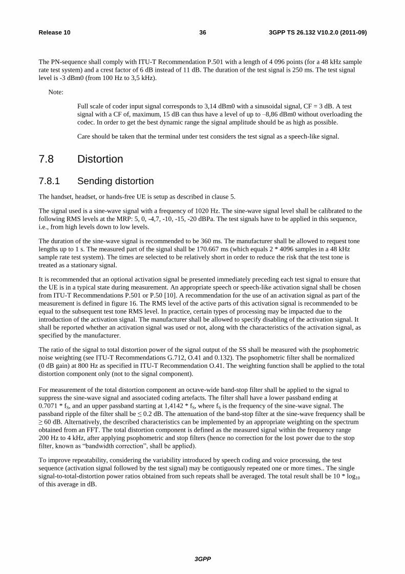
3GPP
3GPP TS 26.132 V10.2.0 (2011-09) 36 Release 10
The PN-sequence shall comply with ITU-T Recommendation P.501 with a length of 4 096 points (for a 48 kHz sample
rate test system) and a crest factor of 6 dB instead of 11 dB. The duration of the test signal is 250 ms. The test signal
level is -3 dBm0 (from 100 Hz to 3,5 kHz).
Note:
Full scale of coder input signal corresponds to 3,14 dBm0 with a sinusoidal signal, CF = 3 dB. A test
signal with a CF of, maximum, 15 dB can thus have a level of up to –8,86 dBm0 without overloading the
codec. In order to get the best dynamic range the signal amplitude should be as high as possible.
Care should be taken that the terminal under test considers the test signal as a speech-like signal.
7.8 Distortion
7.8.1 Sending distortion
The handset, headset, or hands-free UE is setup as described in clause 5.
The signal used is a sine-wave signal with a frequency of 1020 Hz. The sine-wave signal level shall be calibrated to the
following RMS levels at the MRP: 5, 0, -4,7, -10, -15, -20 dBPa. The test signals have to be applied in this sequence,
i.e., from high levels down to low levels.
The duration of the sine-wave signal is recommended to be 360 ms. The manufacturer shall be allowed to request tone
lengths up to 1 s. The measured part of the signal shall be 170.667 ms (which equals 2 * 4096 samples in a 48 kHz
sample rate test system). The times are selected to be relatively short in order to reduce the risk that the test tone is
treated as a stationary signal.
It is recommended that an optional activation signal be presented immediately preceding each test signal to ensure that
the UE is in a typical state during measurement. An appropriate speech or speech-like activation signal shall be chosen
from ITU-T Recommendations P.501 or P.50 [10]. A recommendation for the use of an activation signal as part of the
measurement is defined in figure 16. The RMS level of the active parts of this activation signal is recommended to be
equal to the subsequent test tone RMS level. In practice, certain types of processing may be impacted due to the
introduction of the activation signal. The manufacturer shall be allowed to specify disabling of the activation signal. It
shall be reported whether an activation signal was used or not, along with the characteristics of the activation signal, as
specified by the manufacturer.
The ratio of the signal to total distortion power of the signal output of the SS shall be measured with the psophometric
noise weighting (see ITU-T Recommendations G.712, O.41 and 0.132). The psophometric filter shall be normalized
(0 dB gain) at 800 Hz as specified in ITU-T Recommendation O.41. The weighting function shall be applied to the total
distortion component only (not to the signal component).
For measurement of the total distortion component an octave-wide band-stop filter shall be applied to the signal to
suppress the sine-wave signal and associated coding artefacts. The filter shall have a lower passband ending at
0.7071 * fS, and an upper passband starting at 1,4142 * fS, where fS is the frequency of the sine-wave signal. The
passband ripple of the filter shall be ≤ 0.2 dB. The attenuation of the band-stop filter at the sine-wave frequency shall be
≥ 60 dB. Alternatively, the described characteristics can be implemented by an appropriate weighting on the spectrum
obtained from an FFT. The total distortion component is defined as the measured signal within the frequency range
200 Hz to 4 kHz, after applying psophometric and stop filters (hence no correction for the lost power due to the stop
filter, known as “bandwidth correction”, shall be applied).
To improve repeatability, considering the variability introduced by speech coding and voice processing, the test
sequence (activation signal followed by the test signal) may be contiguously repeated one or more times.. The single
signal-to-total-distortion power ratios obtained from such repeats shall be averaged. The total result shall be 10 * log10
of this average in dB.
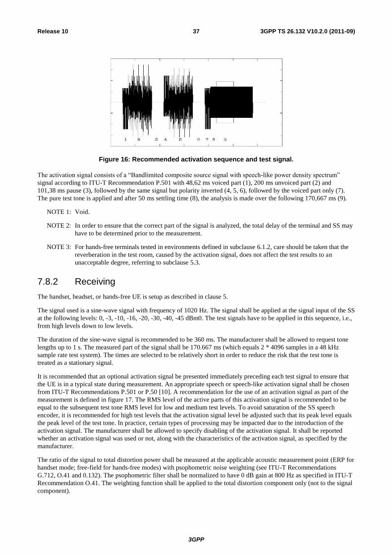
3GPP
3GPP TS 26.132 V10.2.0 (2011-09) 37 Release 10
Figure 16: Recommended activation sequence and test signal.
The activation signal consists of a “Bandlimited composite source signal with speech-like power density spectrum”
signal according to ITU-T Recommendation P.501 with 48,62 ms voiced part (1), 200 ms unvoiced part (2) and
101,38 ms pause (3), followed by the same signal but polarity inverted (4, 5, 6), followed by the voiced part only (7).
The pure test tone is applied and after 50 ms settling time (8), the analysis is made over the following 170,667 ms (9).
NOTE 1: Void.
NOTE 2: In order to ensure that the correct part of the signal is analyzed, the total delay of the terminal and SS may
have to be determined prior to the measurement.
NOTE 3: For hands-free terminals tested in environments defined in subclause 6.1.2, care should be taken that the
reverberation in the test room, caused by the activation signal, does not affect the test results to an
unacceptable degree, referring to subclause 5.3.
7.8.2 Receiving
The handset, headset, or hands-free UE is setup as described in clause 5.
The signal used is a sine-wave signal with frequency of 1020 Hz. The signal shall be applied at the signal input of the SS
at the following levels: 0, -3, -10, -16, -20, -30, -40, -45 dBm0. The test signals have to be applied in this sequence, i.e.,
from high levels down to low levels.
The duration of the sine-wave signal is recommended to be 360 ms. The manufacturer shall be allowed to request tone
lengths up to 1 s. The measured part of the signal shall be 170.667 ms (which equals 2 * 4096 samples in a 48 kHz
sample rate test system). The times are selected to be relatively short in order to reduce the risk that the test tone is
treated as a stationary signal.
It is recommended that an optional activation signal be presented immediately preceding each test signal to ensure that
the UE is in a typical state during measurement. An appropriate speech or speech-like activation signal shall be chosen
from ITU-T Recommendations P.501 or P.50 [10]. A recommendation for the use of an activation signal as part of the
measurement is defined in figure 17. The RMS level of the active parts of this activation signal is recommended to be
equal to the subsequent test tone RMS level for low and medium test levels. To avoid saturation of the SS speech
encoder, it is recommended for high test levels that the activation signal level be adjusted such that its peak level equals
the peak level of the test tone. In practice, certain types of processing may be impacted due to the introduction of the
activation signal. The manufacturer shall be allowed to specify disabling of the activation signal. It shall be reported
whether an activation signal was used or not, along with the characteristics of the activation signal, as specified by the
manufacturer.
The ratio of the signal to total distortion power shall be measured at the applicable acoustic measurement point (ERP for
handset mode; free-field for hands-free modes) with psophometric noise weighting (see ITU-T Recommendations
G.712, O.41 and 0.132). The psophometric filter shall be normalized to have 0 dB gain at 800 Hz as specified in ITU-T
Recommendation O.41. The weighting function shall be applied to the total distortion component only (not to the signal
component).
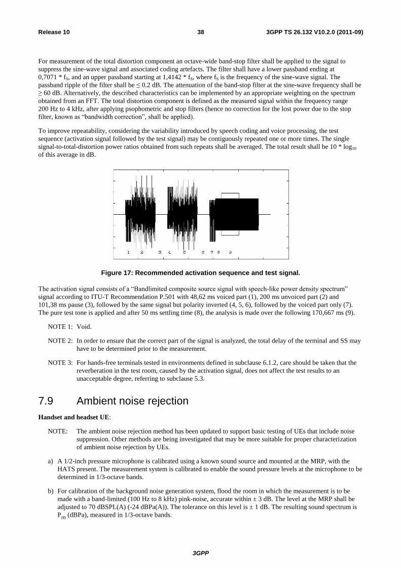
3GPP
3GPP TS 26.132 V10.2.0 (2011-09) 38 Release 10
For measurement of the total distortion component an octave-wide band-stop filter shall be applied to the signal to
suppress the sine-wave signal and associated coding artefacts. The filter shall have a lower passband ending at
0,7071 * fS, and an upper passband starting at 1,4142 * fS, where fS is the frequency of the sine-wave signal. The
passband ripple of the filter shall be ≤ 0.2 dB. The attenuation of the band-stop filter at the sine-wave frequency shall be
≥ 60 dB. Alternatively, the described characteristics can be implemented by an appropriate weighting on the spectrum
obtained from an FFT. The total distortion component is defined as the measured signal within the frequency range
200 Hz to 4 kHz, after applying psophometric and stop filters (hence no correction for the lost power due to the stop
filter, known as “bandwidth correction”, shall be applied).
To improve repeatability, considering the variability introduced by speech coding and voice processing, the test
sequence (activation signal followed by the test signal) may be contiguously repeated one or more times. The single
signal-to-total-distortion power ratios obtained from such repeats shall be averaged. The total result shall be 10 * log10
of this average in dB.
Figure 17: Recommended activation sequence and test signal.
The activation signal consists of a “Bandlimited composite source signal with speech-like power density spectrum”
signal according to ITU-T Recommendation P.501 with 48,62 ms voiced part (1), 200 ms unvoiced part (2) and
101,38 ms pause (3), followed by the same signal but polarity inverted (4, 5, 6), followed by the voiced part only (7).
The pure test tone is applied and after 50 ms settling time (8), the analysis is made over the following 170,667 ms (9).
NOTE 1: Void.
NOTE 2: In order to ensure that the correct part of the signal is analyzed, the total delay of the terminal and SS may
have to be determined prior to the measurement.
NOTE 3: For hands-free terminals tested in environments defined in subclause 6.1.2, care should be taken that the
reverberation in the test room, caused by the activation signal, does not affect the test results to an
unacceptable degree, referring to subclause 5.3.
7.9 Ambient noise rejection
Handset and headset UE:
NOTE: The ambient noise rejection method has been updated to support basic testing of UEs that include noise
suppression. Other methods are being investigated that may be more suitable for proper characterization
of ambient noise rejection by UEs.
a) A 1/2-inch pressure microphone is calibrated using a known sound source and mounted at the MRP, with the
HATS present. The measurement system is calibrated to enable the sound pressure levels at the microphone to be
determined in 1/3-octave bands.
b) For calibration of the background noise generation system, flood the room in which the measurement is to be
made with a band-limited (100 Hz to 8 kHz) pink-noise, accurate within ± 3 dB. The level at the MRP shall be
adjusted to 70 dBSPL(A) (-24 dBPa(A)). The tolerance on this level is ± 1 dB. The resulting sound spectrum is
Prn (dBPa), measured in 1/3-octave bands.
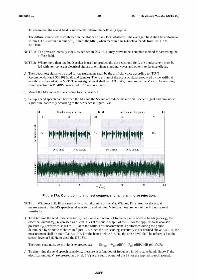
3GPP
3GPP TS 26.132 V10.2.0 (2011-09) 39 Release 10
To ensure that the sound field is sufficiently diffuse, the following applies:
The diffuse sound-field is calibrated in the absence of any local obstacles. The averaged field shall be uniform to
within ± 3 dB within a radius of 0,15 m of the MRP, when measured in 1/3-octave bands from 100 Hz to
3,15 kHz.
NOTE 1: The pressure intensity index, as defined in ISO 9614, may prove to be a suitable method for assessing the
diffuse field.
NOTE 2: Where more than one loudspeaker is used to produce the desired sound field, the loudspeakers must be
fed with non-coherent electrical signals to eliminate standing waves and other interference effects.
c) The speech test signal to be used for measurements shall be the artificial voice according to ITU-T
Recommendation P.50 [10] (male and female). The spectrum of the acoustic signal produced by the artificial
mouth is calibrated at the MRP. The test signal level shall be +1,3 dBPa, measured at the MRP. The resulting
sound spectrum is Po dBPa, measured in 1/3-octave bands.
d) Mount the MS under test, according to subclause 5.1.1.
e) Set up a send speech path between the MS and the SS and reproduce the artificial speech signal and pink noise
signal simultaneously according to the sequence in figure 17a:
0 10 20 30 40 50 60Time (s)
5 s 5 s 10 s
Pin
k n
ois
eA
rtif
icia
l sp
eech
P.50 male P.50 maleP.50 female P.50 female
Conditioning sequence Measurement sequence
I II III IV V
Figure 17a: Conditioning and test sequence for ambient noise rejection.
NOTE: Windows I, II, III are used only for conditioning of the MS. Window IV is used for the actual
measurement of the MS speech send sensitivity and window V for the measurement of the MS noise send
sensitivity.
f) To determine the send noise sensitivity, measure as a function of frequency in 1/3-octave bands (index j), the
electrical output Vjrn, (expressed as dB rel. 1 V) at the audio output of the SS for the applied noise acoustic
pressure Pjrn (expressed as dB rel. 1 Pa) at the MRP. This measurement is performed during the period
determined by window V shown in figure 17a. Since the MS sending sensitivity is not defined above 3,4 kHz, the
measurement shall be cut off at 3,4 kHz. For the bands below 315 Hz, the noise level shall be referenced to the
speech level at 315 Hz to yield the DELSM.
The room send noise sensitivity is expressed as: Sm jrn = Vjrn (dBV) - Pjrn (dBPa) dB rel. 1V/Pa
g) To determine the send speech sensitivity, measure as a function of frequency in 1/3-octave bands (index j) the
electrical output, Vj, (expressed as dB rel. 1 V) at the audio output of the SS for the applied speech acoustic
3GPP
3GPP TS 26.132 V10.2.0 (2011-09) 40 Release 10
pressure, Pj0, (expressed as dB rel. 1 Pa), at the MRP. This measurement is performed during the period
determined by window IV shown in figure 17a.
The speech sending sensitivity is expressed as;
Smjs (dB) = Vj (dBV) - Pjo (dBPa) dB rel. 1 V/Pa.
h) The difference between the room noise sensitivity and the speech sending sensitivity, DELSM ( jSM), in each
1/3-octave band for the MS is determined as:
DELSM ( jSM) = Smjrn - Smjs (dB) (for j = 1 to 2, Smjs = Sm3s).
i) The Ambient noise rejection, ANR, is calculated as a single figure value according to the following formula:
jsiW
i
jSMANR0175.0
13
1
105
4
j = The index of 1/3-octave bands centered at frequencies from 200 Hz to 3150 Hz inclusive.
Wjsi = the sending weighting factors from ITU-T Recommendation P.79 [16], table 1 for the jth
1/3-octave
band centre frequency.
Hands-free UE (all categories):
No test method for hands-free operations.
8 Wideband telephony transmission performance test methods
8.1 Applicability
The test methods in this clause shall apply when testing a UE that is used to provide narrowband or wideband telephony,
either as a stand-alone service, or as part of a multimedia service.
The application force used to apply the handset against the artificial ear shall be 8 ± 2 N. For the headset case, the
application of the headset shall comply with ITU-T Recommendation P.57 [14].
8.2 Overall loss/loudness ratings
8.2.1 General
The SLR and RLR values for GSM or 3G networks apply up to the POI. However, the main determining factors are the
characteristics of the UE, including the analogue to digital conversion (ADC) and digital to analogue conversion (DAC).
In practice, it is convenient to specify loudness ratings to the Air Interface. For the normal case, where the GSM or 3G
network introduce no additional loss between the Air Interface and the POI, the loudness ratings to the PSTN boundary
(POI) will be the same as the loudness ratings measured at the Air Interface.
8.2.2 Connections with handset UE
8.2.2.1 Sending loudness rating (SLR)
a) The test signal to be used for normative measurements shall be the artificial voice according to ITU-T
Recommendation P.50 [10]. Alternatively, a speech-like test signal as described in ITU-T Recommendation
P.501 may be used. The type of test signal used shall be stated in the test report. The spectrum of the acoustic
3GPP
3GPP TS 26.132 V10.2.0 (2011-09) 41 Release 10
signal produced by the artificial mouth is calibrated under free-field conditions at the MRP. The test signal level
shall be –4,7 dBPa measured at the MRP. The test signal level is averaged over the complete test signal
sequence.
b) The handset terminal is setup as described in clause 5. The sending sensitivity shall be calculated from each band
of the 20 frequencies given in table G.1 of ITU-T Recommendation P.79 Annex A [16], bands 1 to 20. For the
calculation, the averaged measured level at the electrical reference point for each frequency band is referred to
the averaged test signal level measured in each frequency band at the MRP.
c) The sensitivity is expressed in terms of dBV/Pa and the SLR shall be calculated according to ITU-T
Recommendation P.79 [16], formula (A-23b), over bands 1 to 20, using m = 0,175 and the sending weighting
factors from ITU-T Recommendation P.79 Annex A [16], table A2.
8.2.2.2 Receiving loudness rating (RLR)
a) The test signal to be used for normative measurements shall be the artificial voice according to ITU-T
Recommendation P.50 [10]. Alternatively, a speech-like test signal as described in ITU-T Recommendation
P.501 may be used. The type of test signal used shall be stated in the test report. The test signal level shall be
-16 dBm0 measured at the digital reference point or the equivalent analogue point. The test signal level is
averaged over the complete test signal sequence.
b) The handset terminal is setup as described in clause 5. The receiving sensitivity shall be calculated from each
band of the 20 frequencies given in table A.2 of ITU-T Recommendation P.79 Annex A [16], bands 1 to 20. For
the calculation, the averaged measured level at each frequency band is referred to the averaged test signal level
measured in each frequency band.
c) The sensitivity is expressed in terms of dBPa/V and the RLR shall be calculated according to ITU-T
Recommendation P.79 [16], formula (A-23c), over bands 1 to 20, using m = 0,175 and the receiving weighting
factors from table A.2 of ITU-T Recommendation P.79 Annex A [16].
d) DRP-ERP correction is applied. No leakage correction shall be applied.
8.2.3 Connections with desktop and vehicle-mounted hands-free UE
Vehicle-mounted hands-free UE should be tested within the vehicle (for the totally integrated vehicle hands-free
systems) or in a vehicle simulator, as described in 3GPP TS 03.58 [11].
Free-field measurements for vehicle-mounted hands-free are for further study.
8.2.3.1 Sending loudness rating (SLR)
a) The test signal to be used for normative measurements shall be the artificial voice according to ITU-T
Recommendation P.50 [10]. Alternatively, a speech-like test signal as described in ITU-T Recommendation
P.501 may be used. The type of test signal used shall be stated in the test report. The spectrum of the acoustic
signal produced by the artificial mouth is calibrated under free-field conditions at the MRP. The test signal level
shall be –4,7 dBPa measured at the MRP. The test signal level is averaged over the complete test signal
sequence. The broadband signal level then is adjusted to –28,7 dBPa at the HFRP or the HATS HFRP (as
defined in ITU-Recommendation P.581) and the spectrum is not altered.
The spectrum at the MRP and the actual level at the MRP (measured in 1/3-octaves) are used as references to
determine the sending sensitivity SmJ.
b) The hands-free terminal is setup as described in clause 5. The sending sensitivity shall be calculated from each
band of the 20 frequencies given in table A.2 of ITU-T Recommendation P.79 Annex A [16], bands 1 to 20. For
the calculation, the averaged measured level at the electrical reference point for each frequency band is referred
to the averaged test signal level measured in each frequency band at the MRP.
c) The sensitivity is expressed in terms of dBV/Pa and the SLR shall be calculated according to ITU-T
Recommendation P.79 [16], formula (A-23b), over bands 1 to 20, using m = 0,175 and the sending weighting
factors from ITU-T Recommendation P.79 Annex A [16], table A.2.
3GPP
3GPP TS 26.132 V10.2.0 (2011-09) 42 Release 10
8.2.3.2 Receiving loudness rating (RLR)
a) The test signal to be used for normative measurements shall be the artificial voice according to ITU-T
Recommendation P.50 [10]. Alternatively, a speech-like test signal as described in ITU-T Recommendation
P.501 may be used. The type of test signal used shall be stated in the test report. The test signal level shall be
-16 dBm0 measured at the digital reference point or the equivalent analogue point. The test signal level is
averaged over the complete test signal sequence.
b) The hands-free terminal is setup as described in clause 5. If a HATS is used, then it is free-field equalized as
described in ITU-T Recommendation P.581. The equalized output signal of each artificial ear is power-averaged
over the total duration of the analysis; the right and left artificial ear signals are voltage-summed for each 1/3-
octave frequency band; these 1/3-octave band data are considered as the input signal to be used for calculations
or measurements. The receiving sensitivity shall be calculated from each band of the 20 frequencies given in
table A.2 of ITU-T Recommendation P.79 Annex A [16], bands 1 to 20.
For the calculation, the averaged measured level at each frequency band is referred to the averaged test signal
level measured in each frequency band.
c) The sensitivity is expressed in terms of dBPa/V and the RLR shall be calculated according to ITU-T
Recommendation P.79 [16], formula (A-23c), over bands 1 to 20, using m = 0,175 and the receiving weighting
factors from table A.2 of ITU-T Recommendation P.79 Annex A [16].
d) No leakage correction shall be applied. The hands-free correction as described in ITU-T Recommendation P.340
shall be applied. To compute the receiving loudness rating (RLR) for a hands-free terminal (see also ITU-T
Recommendation P.340), when using the combination of left and right artificial ear signals from the HATS, the
HFLE has to be 8 dB instead of 14 dB. For further information see ITU-T Recommendation P.581.
8.2.4 Connections with hand-held hands-free UE
8.2.4.1 Sending loudness rating (SLR)
a) The test signal to be used for normative measurements shall be the artificial voice according to ITU-T
Recommendation P.50 [10]. Alternatively, a speech-like test signal as described in ITU-T Recommendation
P.501 may be used. The type of test signal used shall be stated in the test report. The spectrum of the acoustic
signal produced by the artificial mouth is calibrated under free-field conditions at the MRP. The test signal level
shall be –4,7 dBPa measured at the MRP. The test signal level is averaged over the complete test signal
sequence. The broadband signal level then is adjusted to –28,7 dBPa at the HFRP or the HATS HFRP (as
defined in P.581) and the spectrum is not altered.
The spectrum at the MRP and the actual level at the MRP (measured in 1/3-octaves) are used as reference to
determine the sending sensitivity SmJ.
b) The hands-free terminal is setup as described in clause 5. The sending sensitivity shall be calculated from each
band of the 20 frequencies given in table A.2 of ITU-T Recommendation P.79 Annex A [16], bands 1 to 20. For
the calculation the averaged measured level at the electrical reference point for each frequency band is referred to
the averaged test signal level measured in each frequency band at the MRP.
c) The sensitivity is expressed in terms of dBV/Pa and the SLR shall be calculated according to ITU-T
Recommendation P.79 [16], formula (A-23b), over bands 1 to 20, using m = 0,175 and the sending weighting
factors from ITU-T Recommendation P.79 Annex A [16], table A.2.
8.2.4.2 Receiving loudness rating (RLR)
a) The test signal to be used for normative measurements shall be the artificial voice according to ITU-T
Recommendation P.50 [10]. Alternatively, a speech-like test signal as described in ITU-T Recommendation
P.501 may be used. The type of test signal used shall be stated in the test report. The test signal level shall be
-16 dBm0 measured at the digital reference point or the equivalent analogue point. The test signal level is
averaged over the complete test signal sequence.
3GPP
3GPP TS 26.132 V10.2.0 (2011-09) 43 Release 10
b) The hands-free terminal is setup as described in clause 5. If a HATS is used, then it is free-field equalized as
described in ITU-T Recommendation P.581. The equalized output signal of each artificial ear is power-averaged
over the total duration of the analysis; the right and left artificial ear signals are voltage-summed for each 1/3-
octave frequency band; these 1/3-octave band data are considered as the input signal to be used for calculations
or measurements. The receiving sensitivity shall be calculated from each band of the 20 frequencies given in
table A.2 of ITU-T Recommendation P.79 Annex A [16], bands 1 to 20.
For the calculation, the averaged measured level at each frequency band is referred to the averaged test signal
level measured in each frequency band.
c) The sensitivity is expressed in terms of dBPa/V and the RLR shall be calculated according to ITU-T
Recommendation P.79 [16], formula (A-23c), over bands 1 to 20, using m = 0,175 and the receiving weighting
factors from table A.2 of ITU-T Recommendation P.79 Annex A [16].
d) No leakage correction shall be applied. The hands-free correction as described in ITU-T Recommendation P.340
shall be applied. To compute the receiving loudness rating (RLR) for hands-free terminals (see also ITU-T
Recommendation P.340) when using the combination of left and right artificial ear signals from the HATS the
HFLE has to be 8 dB, instead of 14 dB. For further information see ITU-T Recommendation P.581.
8.2.5 Connections with headset UE
Same as for handset.
8.3 Idle channel noise (handset and headset UE)
For idle noise measurements in sending and receiving directions, care should be taken that only the noise is windowed
out by the analysis and the result is not impaired by any remaining reverberation or by noise and/or interference from
various other sources. Some examples are air-conducted or vibration-conducted noise from sources inside or outside the
test chamber, disturbances from lights and regulators, mains supply induced noise including grounding issues, test
system and system simulator inherent noise as well as radio interference from the UE to test equipment such as ear
simulators, microphone amplifiers, etc.
8.3.1 Sending
The terminal should be configured to the test equipment as described in subclause 5.1.
The environment shall comply with the conditions described in subclause 6.1.
The noise level at the output of the SS is measured with A-weighting. The A-weighting filter is described in IEC 60651.
A test signal may have to be intermittently applied to prevent „silent mode‟ operation of the MS. This is for further
study.
The measured part of the noise shall be 170,667 ms (which equals 8192 samples in a 48 kHz sample rate test system).
The spectral distribution of the noise is analyzed with an 8k FFT using windowing with ≤ 0,1 dB leakage for non bin-
centered signals. This can be achieved with a window function commonly known as a “flat top window”. Within the
specified frequency range, the FFT bin that has the highest level is searched for; the level of this bin is the maximum
level of a single frequency disturbance.
To improve repeatability, the test sequence (optional activation followed by the noise level measurement) may be
contiguously repeated one or more times.
The total noise powers obtained from such repeats shall be averaged. The total result shall be 10 * log10 of this average
in dB.
The single frequency maximum powers obtained from such repeats shall be averaged. The total result shall be 10 * log10
of this average in dB.
3GPP
3GPP TS 26.132 V10.2.0 (2011-09) 44 Release 10
8.3.2 Receiving
The terminal should be configured to the test equipment as described in subclause 5.1.
The environment shall comply with the conditions described in subclause 6.1.
A test signal may have to be intermittently applied to prevent „silent mode‟ operation of the MS. This is for further
study.
The noise shall be measured with A-weighting at the DRP with diffuse-field correction. The A-weighting filter is
described in IEC 60651.
The measured part of the noise shall be 170,667 ms (which equals 8192 samples in a 48 kHz sample rate test system).
The spectral distribution of the noise is analyzed with an 8k FFT using windowing with ≤ 0,1 dB leakage for non bin-
centered signals. This can be achieved with a window function commonly known as a “flat top window”. Within the
specified frequency range the FFT bin that has the highest level is searched for; the level of this bin is the maximum
level of a single frequency disturbance.
To improve repeatability, the test sequence (optional activation followed by the noise level measurement) may be
contiguously repeated one or more times.
The total noise powers obtained from such repeats shall be averaged. The total result shall be 10 * log10 of this average
in dB.
The single frequency maximum powers obtained from such repeats shall be averaged. The total result shall be 10 * log10
of this average in dB.
8.4 Sensitivity/frequency characteristics
8.4.1 Handset and headset UE sending
The headset case is similar to the handset one, except for the application force.
a) The test signal to be used for normative measurements shall be the artificial voice according to ITU-T
Recommendation P.50 [10]. Alternatively, a speech-like test signal as described in ITU-T Recommendation
P.501 may be used. The type of test signal used shall be stated in the test report. The spectrum of the acoustic
signal produced by the artificial mouth is calibrated under free-field conditions at the MRP. The test signal level
shall be –4,7 dBPa measured at the MRP. The test signal level is averaged over the complete test signal
sequence.
b) The handset terminal is setup as described in clause 5. Measurements shall be made at 1/12-octave intervals as
given by the R.40 series of preferred numbers in ISO 3 for frequencies from 100 Hz to 8 kHz inclusive. For the
calculation, the averaged measured level at the electrical reference point for each frequency band is referred to
the averaged test signal level measured in each frequency band at the MRP.
c) The sensitivity is expressed in terms of dBV/Pa.
8.4.2 Handset and headset UE receiving
a) The test signal to be used for normative measurements shall be the artificial voice according to ITU-T
Recommendation P.50 [10]. Alternatively, a speech-like test signal as described in ITU-T Recommendation
P.501 may be used. The type of test signal used shall be stated in the test report. The test signal level shall be
-16 dBm0 measured at the digital reference point or the equivalent analogue point. The test signal level is
averaged over the complete test signal sequence.
b) The handset terminal is setup as described in clause 5. Measurements shall be made at 1/12-octave intervals as
given by the R.40 series of preferred numbers in ISO 3 for frequencies from 100 Hz to 8 kHz inclusive. For the
calculation, the averaged measured level at each frequency band is referred to the averaged test signal level
measured in each frequency band.
3GPP
3GPP TS 26.132 V10.2.0 (2011-09) 45 Release 10
c) The HATS is diffuse-field equalized. The sensitivity is expressed in terms of dBPa/V. Information about
correction factors is available in ITU-T Recommendation P.57 [14].
Optionally, the measurements may be repeated with 2 N and 13 N application force. For these test cases no normative
values apply.
8.4.3 Desktop and vehicle-mounted hands-free UE sending
a) The test signal to be used for normative measurements shall be the artificial voice according to ITU-T
Recommendation P.50 [10]. Alternatively, a speech-like test signal as described in ITU-T Recommendation
P.501 may be used. The type of test signal used shall be stated in the test report. The spectrum of the acoustic
signal produced by the artificial mouth is calibrated under free-field conditions at the MRP. The test signal level
shall be –4,7 dBPa measured at the MRP. The test signal level is averaged over the complete test signal
sequence. The broadband signal level is then adjusted to –28,7 dBPa at the HFRP or the HATS HFRP (as
defined in ITU-T Recommendation P.581) and the spectrum is not altered.
The spectrum at the MRP and the actual level at the MRP (measured in 1/3-octaves) are used as references to
determine the sending sensitivity SmJ.
b) The hands-free terminal is setup as described in clause 5. Measurements shall be made at 1/3-octave intervals as
given by the R.40 series of preferred numbers in ISO 3 for frequencies from 100 Hz to 8 kHz inclusive. For the
calculation the averaged measured level at each frequency band is referred to the averaged test signal level
measured in each frequency band.
c) The sensitivity is expressed in terms of dBV/Pa.
8.4.4 Desktop and vehicle-mounted hands-free UE receiving
a) The test signal to be used for normative measurements shall be the artificial voice according to ITU-T
Recommendation P.50 [10]. Alternatively, a speech-like test signal as described in ITU-T Recommendation
P.501 may be used. The type of test signal used shall be stated in the test report. The test signal level shall be
-16 dBm0 measured at the digital reference point or the equivalent analogue point. The test signal level is
averaged over the complete test signal sequence.
b) The hands-free terminal is setup as described in clause 5. If a HATS is used, then it is free-field equalized as
described in ITU-T Recommendation P.581. The equalized output signal of each artificial ear is power-averaged
over the total duration of the analysis; the right and left artificial ear signals are voltage-summed for each 1/3-
octave frequency band; these 1/3-octave band data are considered as the input signal to be used for calculations
or measurements. Measurements shall be made at 1/3-octave intervals as given by the R.40 series of preferred
numbers in ISO 3 for frequencies from 100 Hz to 8 kHz inclusive. For the calculation, the averaged measured
level at each frequency band is referred to the averaged test signal level measured in each frequency band.
c) The sensitivity is expressed in terms of dBPa/V.
8.4.5 Hand-held hands-free UE sending
a) The test signal to be used for normative measurements shall be the artificial voice according to ITU-T
Recommendation P.50 [10]. Alternatively, a speech like test signal as described in ITU-T Recommendation
P.501 may be used. The type of test signal used shall be stated in the test report. The spectrum of the acoustic
signal produced by the artificial mouth is calibrated under free-field conditions at the MRP. The test signal level
shall be –4,7 dBPa measured at the MRP. The test signal level is averaged over the complete test signal
sequence. The broadband signal level is then adjusted to –24,3 dBPa at the HFRP or the HATS HFRP (as
defined in subclause 8.2.3.1) and the spectrum is not altered.
The spectrum at the MRP and the actual level at the MRP (measured in 1/3-octaves) are used as reference to
determine the sending sensitivity SmJ.
b) The hands-free terminal is setup as described in clause 5.1.3.3. Measurements shall be made at 1/3-octave
intervals as given by the R.40 series of preferred numbers in ISO 3 for frequencies from 100 Hz to 8 kHz
3GPP
3GPP TS 26.132 V10.2.0 (2011-09) 46 Release 10
inclusive. For the calculation, the averaged measured level at each frequency band is referred to the averaged test
signal level measured in each frequency band.
c) The sensitivity is expressed in terms of dBV/Pa.
8.4.6 Hand-held hands-free UE receiving
a) The test signal to be used for normative measurements shall be the artificial voice according to ITU-T
Recommendation P.50 [10]. Alternatively, a speech-like test signal as described in ITU-T Recommendation
P.501 may be used. The type of test signal used shall be stated in the test report. The test signal level shall be
-16 dBm0 measured at the digital reference point or the equivalent analogue point. The test signal level is
averaged over the complete test signal sequence.
b) The hands-free terminal is setup as described in clause 5. If a HATS is used, then it is free-field equalized as
described in ITU-T Recommendation P.581. The equalized output signal of each artificial ear is power-averaged
over the total duration of the analysis; the right and left artificial ear signals are voltage-summed for each 1/3-
octave band frequency band; these 1/3-octave band data are considered as the input signal to be used for
calculations or measurements. Measurements shall be made at 1/3-octave intervals as given by the R.40 series of
preferred numbers in ISO 3 for frequencies from 100 Hz to 8 kHz inclusive. For the calculation, the averaged
measured level at each frequency band is referred to the averaged test signal level measured in each frequency
band.
c) The sensitivity is expressed in terms of dBPa/V.
8.5 Sidetone characteristics
8.5.1 Connections with handset UE
The test signal to be used for normative measurements shall be the artificial voice according to ITU-T Recommendation
P.50 [10]. Alternatively, a speech-like test signal as described in ITU-T Recommendation P.501 may be used. The type
of test signal used shall be stated in the test report. The spectrum of the acoustic signal shall be produced by the HATS.
The test signal level shall be -4,7 dBPa measured at the MRP. The test signal level is averaged over the complete test
signal sequence.
The handset UE is set up as described in clause 5. The application force shall be 13 N on the Type 3.3 artificial ear.
Where a user-operated volume control is provided, the measurements shall be carried out at the nominal setting of the
volume control. In addition the measurement is repeated at the maximum volume control setting.
Measurements shall be made at 1/12-octave intervals as given by the R.40 series of preferred numbers in ISO 3 for
frequencies from 100 Hz to 8 kHz inclusive. For the calculation, the averaged measured level at each frequency band
(ITU-T Recommendation P.79 [16], table 4, bands 1 to 20) is referred to the averaged test signal level measured in each
frequency band.
The sidetone path loss (LmeST), as expressed in dB, and the Sidetone Masking Rating (STMR), expressed in dB, shall
be calculated from formula 5-1 of ITU-T Recommendation P.79 [16], using m = 0.225 and the weighting factors in
table B2 (unsealed condition) of ITU-T Recommendation P.79 [16]. No leakage correction (LE) shall be applied. DRP-
ERP correction is used.
8.5.2 Headset UE
The test signal to be used for normative measurements shall be the artificial voice according to ITU-T Recommendation
P.50 [10]. Alternatively, a speech-like test signal as described in ITU-T Recommendation P.501 may be used. The type
of test signal used shall be stated in the test report. The spectrum of the acoustic signal produced by the artificial mouth
is calibrated under free-field conditions at the MRP. The test signal level shall be –4,7 dBPa measured at the MRP. The
test signal level is averaged over the complete test signal sequence.
Measurements shall be made at 1/12-octave intervals as given by the R.40 series of preferred numbers in ISO 3 for
frequencies from 100 Hz to 8 kHz inclusive. For the calculation, the averaged measured level at each frequency band
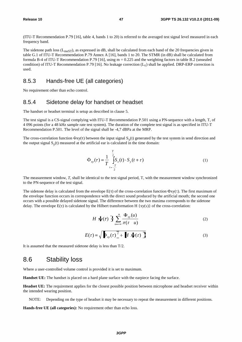
3GPP
3GPP TS 26.132 V10.2.0 (2011-09) 47 Release 10
(ITU-T Recommendation P.79 [16], table 4, bands 1 to 20) is referred to the averaged test signal level measured in each
frequency band.
The sidetone path loss (LmeST), as expressed in dB, shall be calculated from each band of the 20 frequencies given in
table G.1 of ITU-T Recommendation P.79 Annex A [16], bands 1 to 20. The STMR (in dB) shall be calculated from
formula B-4 of ITU-T Recommendation P.79 [16], using m = 0.225 and the weighting factors in table B.2 (unsealed
condition) of ITU-T Recommendation P.79 [16]. No leakage correction (LE) shall be applied. DRP-ERP correction is
used.
8.5.3 Hands-free UE (all categories)
No requirement other than echo control.
8.5.4 Sidetone delay for handset or headset
The handset or headset terminal is setup as described in clause 5.
The test signal is a CS-signal complying with ITU-T Recommendation P.501 using a PN-sequence with a length, T, of
4 096 points (for a 48 kHz sample rate test system). The duration of the complete test signal is as specified in ITU-T
Recommendation P.501. The level of the signal shall be -4,7 dBPa at the MRP.
The cross-correlation function xy( ) between the input signal Sx(t) generated by the test system in send direction and
the output signal Sy(t) measured at the artificial ear is calculated in the time domain:
)()(1
)(2
2
tStST
y
T
Tt
xxy (1)
The measurement window, T, shall be identical to the test signal period, T, with the measurement window synchronized
to the PN-sequence of the test signal.
The sidetone delay is calculated from the envelope E( ) of the cross-correlation function xy( ). The first maximum of
the envelope function occurs in correspondence with the direct sound produced by the artificial mouth; the second one
occurs with a possible delayed sidetone signal. The difference between the two maxima corresponds to the sidetone
delay. The envelope E( ) is calculated by the Hilbert transformation H {xy( )} of the cross-correlation:
u
xy
u
uxyH
)(
)()( (2)
22
)()()( xyHE xy
(3)
It is assumed that the measured sidetone delay is less than T/2.
8.6 Stability loss
Where a user-controlled volume control is provided it is set to maximum.
Handset UE: The handset is placed on a hard plane surface with the earpiece facing the surface.
Headset UE: The requirement applies for the closest possible position between microphone and headset receiver within
the intended wearing position.
NOTE: Depending on the type of headset it may be necessary to repeat the measurement in different positions.
Hands-free UE (all categories): No requirement other than echo loss.

3GPP
3GPP TS 26.132 V10.2.0 (2011-09) 48 Release 10
Before the actual test a training sequence consisting of 10 s male artificial voice and 10 s female artificial voice
according to ITU-T Recommendation P.50 [10] is applied. The training sequence level shall be -16 dBm0 in order to
not overload the codec.
The test signal is a PN-sequence complying with ITU-T Recommendation P.501 with a length of 4 096 points (for a
48 kHz sampling rate system) and a crest factor of 6 dB instead of 11 dB. The duration of the test signal is 250 ms. With
an input signal of -3 dBm0, the attenuation from input to output of the system simulator shall be measured under the
following conditions:
a) The handset or the headset, with the transmission circuit fully active, shall be positioned on a hard plane surface
with at least 400 mm free space in all directions. The earpiece shall face towards the surface as shown in
figure 17c;
b) The headset microphone is positioned as close as possible to the receiver(s) within the intended wearing position;
c) For a binaural headset, the receivers are placed symmetrically around the microphone.
Area of
Test Setup
min 500 mm
min 400 mm
Clear Area
min 400 mm
Clear Area
Surface min 500 mm
NOTE: All dimensions in mm.
Figure 17c. Test configuration for stability loss measurement on handset or headset UE
The attenuation from input to output shall be measured in the frequency range from 100 Hz to 8 kHz. The spectral
distribution of the output signal is analysed with a 4k FFT (for a 48 kHz sample rate test system), thus the measured part
of the output signal is 85,333 ms. To avoid leakage effects the frequency resolution of the FFT must be the same as the
frequency spacing of the PN-sequence.
3GPP
3GPP TS 26.132 V10.2.0 (2011-09) 49 Release 10
8.7 Acoustic echo control
8.7.1 General
The echo loss (EL) presented by the GSM or 3G networks at the POI should be at least 46 dB during single talk. This
value takes into account the fact that UE is likely to be used in a wide range of noise environments.
8.7.2 Acoustic echo control in a hands-free UE
The hands-free UE is setup in a room with acoustic properties similar to a typical “office-type” room; a vehicle-mounted
hands-free UE should be tested in a vehicle or vehicle simulator, as specified by the UE manufacturer (see also 3GPP
TS 03.58 [11]). The ambient noise level shall be less than -70 dBPa(A). The attenuation from reference point input to
reference point output shall be measured using a speech-like test signal.
The TCLw is calculated according to ITU-T Recommendation G.122 [8], annex B, clause B.4 (trapezoidal rule). For the
calculation, the averaged measured echo level at each frequency band is referred to the averaged test signal level
measured in each frequency band.
Before the actual test a training sequence consisting of 10 s male artificial voice and 10 s female artificial voice
according to ITU-T Recommendation P.50 [10] is applied. The training sequence level shall be presented at a level of
-16 dBm0 in order to not overload the codec.
Either a logarithmically spaced multi-sine or a PN-sequence test signal shall be used.
Logarithmically spaced multi-sine:
When using a logarithmically spaced multi-sine test signal, it is defined as:
i
iAMAM ftftAts 0*2cos**2cos)(
with A = 0,5
fAM = 4 Hz, AM = 0,5
f0 i = 250 Hz * 2(i/3)
;i = 1..11
CF = 14 dB ± 1 dB (10 dB + 4,26 dB due to 100% AM modulation)
CF = Crest Factor = Peak to RMS ratio
The test signal level shall be -10 dBm0. The length of the test signal shall be ≥ 1,0 s.
PN-sequence:
The PN-sequence shall comply with ITU-T Recommendation P.501 with a length of 4 096 points (for a 48 kHz
sampling rate system) and a crest factor of 6 dB instead of 11 dB. The duration of the test signal is 250 ms. The test
signal level is -3 dBm0 (from 50 Hz to 7 kHz).
Note:
Full scale of coder input signal corresponds to 3,14 dBm0 with a sinusoidal signal, CF = 3dB. A test
signal with a CF of, maximum, 15 dB can thus have a level of up to –8,86 dBm0 without overloading the
codec. In order to get the best dynamic range the signal amplitude should be as high as possible.
Care should be taken that the terminal under test considers the test signal as a speech-like signal.
8.7.3 Acoustic echo control in a handset UE
The handset is set up according to clause 5. The ambient noise level shall be ≤ -64 dBPa(A). The attenuation from the
reference point input to reference point output shall be measured using the speech-like test signal defined below.
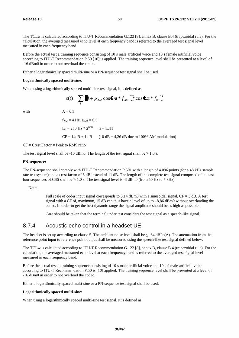
3GPP
3GPP TS 26.132 V10.2.0 (2011-09) 50 Release 10
The TCLw is calculated according to ITU-T Recommendation G.122 [8], annex B, clause B.4 (trapezoidal rule). For the
calculation, the averaged measured echo level at each frequency band is referred to the averaged test signal level
measured in each frequency band.
Before the actual test a training sequence consisting of 10 s male artificial voice and 10 s female artificial voice
according to ITU-T Recommendation P.50 [10] is applied. The training sequence level shall be presented at a level of
-16 dBm0 in order to not overload the codec.
Either a logarithmically spaced multi-sine or a PN-sequence test signal shall be used.
Logarithmically spaced multi-sine:
When using a logarithmically spaced multi-sine test signal, it is defined as:
i
iAMAM ftftAts 0*2cos**2cos)(
with A = 0,5
fAM = 4 Hz, AM = 0,5
f0 i = 250 Hz * 2(i/3)
;i = 1..11
CF = 14dB ± 1 dB (10 dB + 4,26 dB due to 100% AM modulation)
CF = Crest Factor = Peak to RMS ratio
The test signal level shall be -10 dBm0. The length of the test signal shall be ≥ 1,0 s.
PN-sequence:
The PN-sequence shall comply with ITU-T Recommendation P.501 with a length of 4 096 points (for a 48 kHz sample
rate test system) and a crest factor of 6 dB instead of 11 dB. The length of the complete test signal composed of at least
four sequences of CSS shall be ≥ 1,0 s. The test signal level is -3 dBm0 (from 50 Hz to 7 kHz).
Note:
Full scale of coder input signal corresponds to 3,14 dBm0 with a sinusoidal signal, CF = 3 dB. A test
signal with a CF of, maximum, 15 dB can thus have a level of up to –8,86 dBm0 without overloading the
codec. In order to get the best dynamic range the signal amplitude should be as high as possible.
Care should be taken that the terminal under test considers the test signal as a speech-like signal.
8.7.4 Acoustic echo control in a headset UE
The headset is set up according to clause 5. The ambient noise level shall be ≤ -64 dBPa(A). The attenuation from the
reference point input to reference point output shall be measured using the speech-like test signal defined below.
The TCLw is calculated according to ITU-T Recommendation G.122 [8], annex B, clause B.4 (trapezoidal rule). For the
calculation, the averaged measured echo level at each frequency band is referred to the averaged test signal level
measured in each frequency band.
Before the actual test, a training sequence consisting of 10 s male artificial voice and 10 s female artificial voice
according to ITU-T Recommendation P.50 is [10] applied. The training sequence level shall be presented at a level of
-16 dBm0 in order to not overload the codec.
Either a logarithmically spaced multi-sine or a PN-sequence test signal shall be used.
Logarithmically spaced multi-sine:
When using a logarithmically spaced multi-sine test signal, it is defined as:
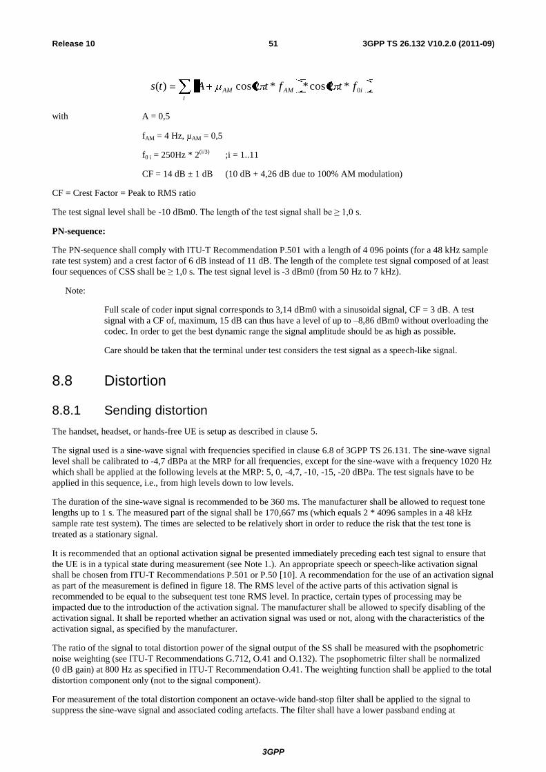
3GPP
3GPP TS 26.132 V10.2.0 (2011-09) 51 Release 10
i
iAMAM ftftAts 0*2cos**2cos)(
with A = 0,5
fAM = 4 Hz, AM = 0,5
f0 i = 250Hz * 2(i/3)
;i = 1..11
CF = 14 dB ± 1 dB (10 dB + 4,26 dB due to 100% AM modulation)
CF = Crest Factor = Peak to RMS ratio
The test signal level shall be -10 dBm0. The length of the test signal shall be ≥ 1,0 s.
PN-sequence:
The PN-sequence shall comply with ITU-T Recommendation P.501 with a length of 4 096 points (for a 48 kHz sample
rate test system) and a crest factor of 6 dB instead of 11 dB. The length of the complete test signal composed of at least
four sequences of CSS shall be ≥ 1,0 s. The test signal level is -3 dBm0 (from 50 Hz to 7 kHz).
Note:
Full scale of coder input signal corresponds to 3,14 dBm0 with a sinusoidal signal, CF = 3 dB. A test
signal with a CF of, maximum, 15 dB can thus have a level of up to –8,86 dBm0 without overloading the
codec. In order to get the best dynamic range the signal amplitude should be as high as possible.
Care should be taken that the terminal under test considers the test signal as a speech-like signal.
8.8 Distortion
8.8.1 Sending distortion
The handset, headset, or hands-free UE is setup as described in clause 5.
The signal used is a sine-wave signal with frequencies specified in clause 6.8 of 3GPP TS 26.131. The sine-wave signal
level shall be calibrated to -4,7 dBPa at the MRP for all frequencies, except for the sine-wave with a frequency 1020 Hz
which shall be applied at the following levels at the MRP: 5, 0, -4,7, -10, -15, -20 dBPa. The test signals have to be
applied in this sequence, i.e., from high levels down to low levels.
The duration of the sine-wave signal is recommended to be 360 ms. The manufacturer shall be allowed to request tone
lengths up to 1 s. The measured part of the signal shall be 170,667 ms (which equals 2 * 4096 samples in a 48 kHz
sample rate test system). The times are selected to be relatively short in order to reduce the risk that the test tone is
treated as a stationary signal.
It is recommended that an optional activation signal be presented immediately preceding each test signal to ensure that
the UE is in a typical state during measurement (see Note 1.). An appropriate speech or speech-like activation signal
shall be chosen from ITU-T Recommendations P.501 or P.50 [10]. A recommendation for the use of an activation signal
as part of the measurement is defined in figure 18. The RMS level of the active parts of this activation signal is
recommended to be equal to the subsequent test tone RMS level. In practice, certain types of processing may be
impacted due to the introduction of the activation signal. The manufacturer shall be allowed to specify disabling of the
activation signal. It shall be reported whether an activation signal was used or not, along with the characteristics of the
activation signal, as specified by the manufacturer.
The ratio of the signal to total distortion power of the signal output of the SS shall be measured with the psophometric
noise weighting (see ITU-T Recommendations G.712, O.41 and O.132). The psophometric filter shall be normalized
(0 dB gain) at 800 Hz as specified in ITU-T Recommendation O.41. The weighting function shall be applied to the total
distortion component only (not to the signal component).
For measurement of the total distortion component an octave-wide band-stop filter shall be applied to the signal to
suppress the sine-wave signal and associated coding artefacts. The filter shall have a lower passband ending at
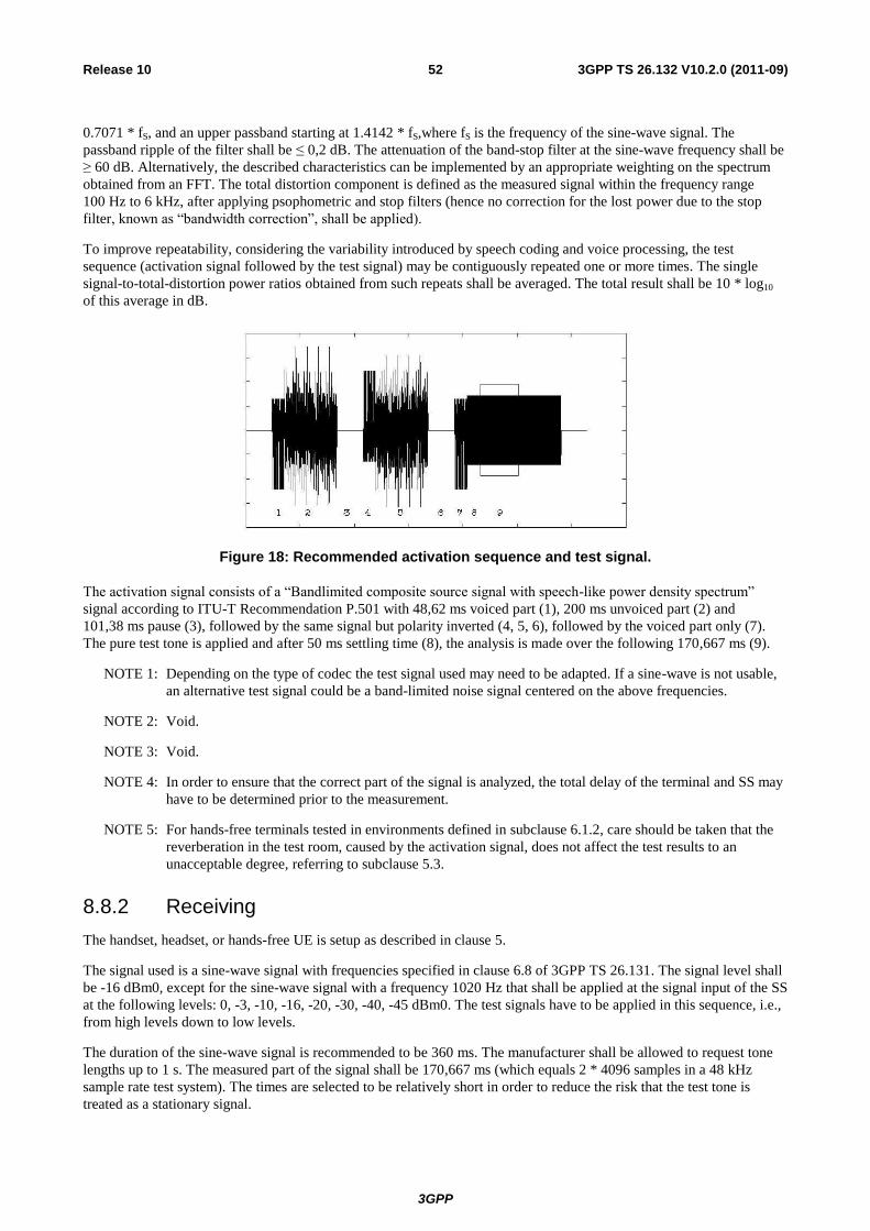
3GPP
3GPP TS 26.132 V10.2.0 (2011-09) 52 Release 10
0.7071 * fS, and an upper passband starting at 1.4142 * fS,where fS is the frequency of the sine-wave signal. The
passband ripple of the filter shall be ≤ 0,2 dB. The attenuation of the band-stop filter at the sine-wave frequency shall be
≥ 60 dB. Alternatively, the described characteristics can be implemented by an appropriate weighting on the spectrum
obtained from an FFT. The total distortion component is defined as the measured signal within the frequency range
100 Hz to 6 kHz, after applying psophometric and stop filters (hence no correction for the lost power due to the stop
filter, known as “bandwidth correction”, shall be applied).
To improve repeatability, considering the variability introduced by speech coding and voice processing, the test
sequence (activation signal followed by the test signal) may be contiguously repeated one or more times. The single
signal-to-total-distortion power ratios obtained from such repeats shall be averaged. The total result shall be 10 * log10
of this average in dB.
Figure 18: Recommended activation sequence and test signal.
The activation signal consists of a “Bandlimited composite source signal with speech-like power density spectrum”
signal according to ITU-T Recommendation P.501 with 48,62 ms voiced part (1), 200 ms unvoiced part (2) and
101,38 ms pause (3), followed by the same signal but polarity inverted (4, 5, 6), followed by the voiced part only (7).
The pure test tone is applied and after 50 ms settling time (8), the analysis is made over the following 170,667 ms (9).
NOTE 1: Depending on the type of codec the test signal used may need to be adapted. If a sine-wave is not usable,
an alternative test signal could be a band-limited noise signal centered on the above frequencies.
NOTE 2: Void.
NOTE 3: Void.
NOTE 4: In order to ensure that the correct part of the signal is analyzed, the total delay of the terminal and SS may
have to be determined prior to the measurement.
NOTE 5: For hands-free terminals tested in environments defined in subclause 6.1.2, care should be taken that the
reverberation in the test room, caused by the activation signal, does not affect the test results to an
unacceptable degree, referring to subclause 5.3.
8.8.2 Receiving
The handset, headset, or hands-free UE is setup as described in clause 5.
The signal used is a sine-wave signal with frequencies specified in clause 6.8 of 3GPP TS 26.131. The signal level shall
be -16 dBm0, except for the sine-wave signal with a frequency 1020 Hz that shall be applied at the signal input of the SS
at the following levels: 0, -3, -10, -16, -20, -30, -40, -45 dBm0. The test signals have to be applied in this sequence, i.e.,
from high levels down to low levels.
The duration of the sine-wave signal is recommended to be 360 ms. The manufacturer shall be allowed to request tone
lengths up to 1 s. The measured part of the signal shall be 170,667 ms (which equals 2 * 4096 samples in a 48 kHz
sample rate test system). The times are selected to be relatively short in order to reduce the risk that the test tone is
treated as a stationary signal.
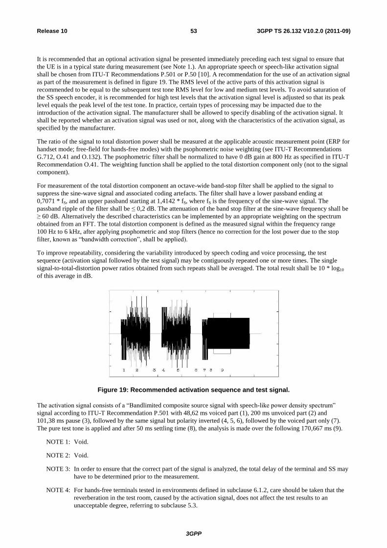
3GPP
3GPP TS 26.132 V10.2.0 (2011-09) 53 Release 10
It is recommended that an optional activation signal be presented immediately preceding each test signal to ensure that
the UE is in a typical state during measurement (see Note 1.). An appropriate speech or speech-like activation signal
shall be chosen from ITU-T Recommendations P.501 or P.50 [10]. A recommendation for the use of an activation signal
as part of the measurement is defined in figure 19. The RMS level of the active parts of this activation signal is
recommended to be equal to the subsequent test tone RMS level for low and medium test levels. To avoid saturation of
the SS speech encoder, it is recommended for high test levels that the activation signal level is adjusted so that its peak
level equals the peak level of the test tone. In practice, certain types of processing may be impacted due to the
introduction of the activation signal. The manufacturer shall be allowed to specify disabling of the activation signal. It
shall be reported whether an activation signal was used or not, along with the characteristics of the activation signal, as
specified by the manufacturer.
The ratio of the signal to total distortion power shall be measured at the applicable acoustic measurement point (ERP for
handset mode; free-field for hands-free modes) with the psophometric noise weighting (see ITU-T Recommendations
G.712, O.41 and O.132). The psophometric filter shall be normalized to have 0 dB gain at 800 Hz as specified in ITU-T
Recommendation O.41. The weighting function shall be applied to the total distortion component only (not to the signal
component).
For measurement of the total distortion component an octave-wide band-stop filter shall be applied to the signal to
suppress the sine-wave signal and associated coding artefacts. The filter shall have a lower passband ending at
0,7071 * fS, and an upper passband starting at 1,4142 * fS, where fS is the frequency of the sine-wave signal. The
passband ripple of the filter shall be ≤ 0,2 dB. The attenuation of the band stop filter at the sine-wave frequency shall be
≥ 60 dB. Alternatively the described characteristics can be implemented by an appropriate weighting on the spectrum
obtained from an FFT. The total distortion component is defined as the measured signal within the frequency range
100 Hz to 6 kHz, after applying psophometric and stop filters (hence no correction for the lost power due to the stop
filter, known as “bandwidth correction”, shall be applied).
To improve repeatability, considering the variability introduced by speech coding and voice processing, the test
sequence (activation signal followed by the test signal) may be contiguously repeated one or more times. The single
signal-to-total-distortion power ratios obtained from such repeats shall be averaged. The total result shall be 10 * log10
of this average in dB.
Figure 19: Recommended activation sequence and test signal.
The activation signal consists of a “Bandlimited composite source signal with speech-like power density spectrum”
signal according to ITU-T Recommendation P.501 with 48,62 ms voiced part (1), 200 ms unvoiced part (2) and
101,38 ms pause (3), followed by the same signal but polarity inverted (4, 5, 6), followed by the voiced part only (7).
The pure test tone is applied and after 50 ms settling time (8), the analysis is made over the following 170,667 ms (9).
NOTE 1: Void.
NOTE 2: Void.
NOTE 3: In order to ensure that the correct part of the signal is analyzed, the total delay of the terminal and SS may
have to be determined prior to the measurement.
NOTE 4: For hands-free terminals tested in environments defined in subclause 6.1.2, care should be taken that the
reverberation in the test room, caused by the activation signal, does not affect the test results to an
unacceptable degree, referring to subclause 5.3.
3GPP
3GPP TS 26.132 V10.2.0 (2011-09) 54 Release 10
8.9 Ambient noise rejection
Handset and headset UE:
NOTE: The ambient noise rejection method has been updated to support basic testing of UEs that include noise
suppression. Other methods are being investigated that may be more suitable for proper characterization
of ambient noise rejection by UEs.
a) A 1/2-inch pressure microphone is calibrated using a known sound source and mounted at the MRP, with the
HATS present. The measurement system is calibrated to enable the sound pressure levels at the microphone to be
determined in 1/3-octave bands.
b) For calibration of the background noise generation system, flood the room in which the measurement is to be
made with a band-limited (100 Hz to 8 kHz) pink-noise, accurate within ± 3 dB. The level at the MRP shall be
adjusted to 70 dBSPL(A) (-24 dBPa(A)). The tolerance on this level is ± 1 dB. The resulting sound spectrum is
Prn (dBPa), measured in 1/3-octave bands.
To ensure that the sound field is sufficiently diffuse, the following applies:
The diffuse sound-field is calibrated in the absence of any local obstacles. The averaged field shall be uniform to
within ± 3 dB within a radius of 0,15 m of the MRP, when measured in 1/3-octave bands from 100 Hz to
6,3 kHz.
NOTE 1: The pressure intensity index, as defined in ISO 9614, may prove to be a suitable method for assessing the
diffuse field.
NOTE 2: Where more than one loudspeaker is used to produce the desired sound field, the loudspeakers must be
fed with non-coherent electrical signals to eliminate standing waves and other interference effects.
c) The speech test signal to be used for measurements shall be the artificial voice according to ITU-T
Recommendation P.50 [10] (male and female). The spectrum of the acoustic signal produced by the artificial
mouth is calibrated at the MRP. The test signal level shall be +1,3 dBPa, measured at the MRP. The resulting
sound spectrum is Po (dBPa), measured in 1/3-octave bands.
d) Mount the MS under test, according to subclause 5.1.1.
e) Set up a send speech path between the MS and the SS and reproduce the artificial speech signal and pink noise
signal simultaneously according to the sequence in figure 19a:

3GPP
3GPP TS 26.132 V10.2.0 (2011-09) 55 Release 10
0 10 20 30 40 50 60Time (s)
5 s 5 s 10 s
Pin
k n
ois
eA
rtif
icia
l sp
eech
P.50 male P.50 maleP.50 female P.50 female
Conditioning sequence Measurement sequence
I II III IV V
Figure 19a: Conditioning and test sequence for ambient noise rejection.
NOTE: Windows I, II, III are used only for conditioning of the MS. Window IV is used for the actual
measurement of the MS speech send sensitivity and window V for the measurement of the MS noise send
sensitivity.
f) To determine the send noise sensitivity, measure as a function of frequency in 1/3-octave bands (index j), the
electrical output, Vjrn, (expressed as dB rel. 1 V) at the audio output of the SS for the applied noise acoustic
pressure Pjrn (expressed as dB rel. 1 Pa) at the MRP. This measurement is performed during the period
determined by window V shown in figure 19a. Since the MS sending sensitivity is not defined above 6,3 kHz, the
measurement shall be cut off at 6,3 kHz. For the bands below 315 Hz, the send noise sensitivity shall be
referenced to the send speech sensitivity at 315 Hz to yield the DELSM.
The send noise sensitivity is expressed as:
Sm jrn = Vjrn (dBV) - Pjrn (dBPa).
g) To determine the send speech sensitivity, measure as a function of frequency in 1/3-octave bands (index j) the
electrical output, Vj, (expressed as dB rel. 1 V), at the audio output of the SS for the applied speech acoustic
pressure, Pj0, (expressed as dB rel. 1 Pa), at the MRP. This measurement is performed during the period
determined by window IV shown in figure 19a.
The send speech sensitivity is expressed as:
Smjs (dB) = Vj (dBV) - Pjo (dBPa) dB rel. 1 V/Pa.
h) The difference between the room noise sensitivity and the speech sending sensitivity DELSM ( jSM) in each 1/3-
octave band for the MS is determined as:
DELSM ( jSM) = Smjrn - Smjs (dB) (for j = 1 to 2, Smjs = Sm3s).
i) The Ambient noise rejection ANR is calculated as a single figure value according to the following formula:
jsiW
i
jSMANR0175.0
16
1
105
4
j = The index of 1/3-octave bands centered at frequencies from 200 Hz to 6300 Hz inclusive.
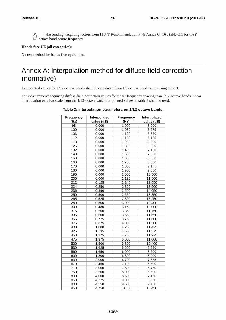
3GPP
3GPP TS 26.132 V10.2.0 (2011-09) 56 Release 10
Wjsi = the sending weighting factors from ITU-T Recommendation P.79 Annex G [16], table G.1 for the jth
1/3-octave band centre frequency.
Hands-free UE (all categories):
No test method for hands-free operations.
Annex A: Interpolation method for diffuse-field correction (normative)
Interpolated values for 1/12-octave bands shall be calculated from 1/3-octave band values using table 3.
For measurements requiring diffuse-field correction values for closer frequency spacing than 1/12-octave bands, linear
interpolation on a log scale from the 1/12-octave band interpolated values in table 3 shall be used.
Table 3: Interpolation parameters on 1/12-octave bands.
Frequency
(Hz) Interpolated
value (dB) Frequency
(Hz) Interpolated
value (dB) 95 0,000 1 000 5,000
100 0,000 1 060 5,375 106 0,000 1 120 5,750 112 0,000 1 180 6,125 118 0,000 1 250 6,500 125 0,000 1 320 6,800 132 0,000 1 400 7,150 140 0,000 1 500 7,550 150 0,000 1 600 8,000 160 0,000 1 700 8,550 170 0,000 1 800 9,175 180 0,000 1 900 9,850 190 0,000 2 000 10,500 200 0,000 2 120 11,500 212 0,125 2 240 12,550 224 0,250 2 360 13,500 236 0,390 2 500 14,050 250 0,500 2 650 13,850 265 0,525 2 800 13,250 280 0,500 3 000 12,400 300 0,480 3 150 12,000 315 0,500 3 350 11,750 335 0,600 3 550 11,650 355 0,725 3 750 11,600 375 0,875 4 000 11,500 400 1,000 4 250 11,425 425 1,135 4 500 11,375 450 1,275 4 750 11,275 475 1,375 5 000 11,000 500 1,500 5 300 10,400 530 1,625 5 600 9,550 560 1,650 6 000 8,600 600 1,800 6 300 8,000 630 2,000 6 700 7,375 670 2,450 7 100 6,800 710 3,000 7 500 6,450 750 3,500 8 000 6,500 800 4,000 8 500 7,150 850 4,325 9 000 8,250 900 4,550 9 500 9,450 950 4,750 10 000 10,450
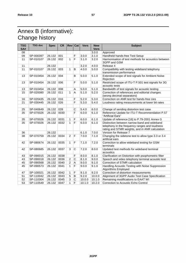
3GPP
3GPP TS 26.132 V10.2.0 (2011-09) 57 Release 10
Annex B (informative): Change history
TSG
SA#
TSG doc Spec CR Rev Cat Vers New
Vers
Subject
08 3.0.0 Approved
09 SP-000397 26.132 001 F 3.0.0 3.1.0 Handheld hands-free Test Setup
11 SP-010107 26.132 002 1 F 3.1.0 3.2.0 Harmonisation of test methods for acoustics between 3GPP and GSM
11 26.132 3.2.0 4.0.0 Release 4
11 SP-010107 26.132 003 1 B 4.0.0 5.0.0 Compatibility with testing wideband telephony transmission performance
13 SP-010454 26.132 004 B 5.0.0 5.1.0 Extended scope of test signals for Ambient Noise Rejection
13 SP-010454 26.132 006 F 5.0.0 5.1.0 Restricted scope of ITU-T P.501 test signals for 3G acoustic tests
13 SP-010454 26.132 008 A 5.0.0 5.1.0 Bandwidth of test signals for acoustic testing
15 SP-020080 26.132 011 1 A 5.1.0 5.2.0 Correction of references and editorial changes (wrong decimal separators)
16 SP-020435 26.132 016 F 5.2.0 5.3.0 Correction on ANR test for hands-free Ues
21 SP-030445 26.132 026 F 5.3.0 5.4.0 Loudness rating measurements at lower bit rates
25 SP-040649 26.132 028 C 5.4.0 6.0.0 Change of sending distortion test case
35 SP-070026 26.132 0030 F 6.0.0 6.1.0 Reference Update for ITU-T Recommendation P.57 “Artificial Ears”
35 SP-070026 26.132 0031 1 F 6.0.0 6.1.0 Update of reference [16] to P.79-2001 Annex G
35 SP-070026 26.132 0032 1 F 6.0.0 6.1.0 Distinction between narrow-band and wideband telephony in the frequency ranges and loudness rating and STMR weights, and in ANR calculation
36 26.132 6.1.0 7.0.0 Version for Release 7
38 SP-070759 26.132 0034 2 F 7.0.0 7.1.0 Changing the sidetone test to allow type 3.3 or 3.4 artificial ears
42 SP-080674 26.132 0035 1 F 7.1.0 7.2.0 Correction to allow wideband testing for GSM terminals
42 SP-080685 26.132 0037 3 C 7.2.0 8.0.0 Updated test methods for wideband terminal acoustics
43 SP-090015 26.132 0038 F 8.0.0 8.1.0 Clarification on Distortion with psophometric filter
43 SP-090018 26.132 0036 2 C 8.1.0 9.0.0 Speech and video telephony terminal acoustic test
45 SP-090568 26.132 0040 2 A 9.0.0 9.1.0 Correction of STMR calculation
45 SP-090573 26.132 0041 1 F 9.0.0 9.1.0 Handling Acoustic Testing with Noise Suppression Algorithms Employed
47 SP-100021 26.132 0042 1 F 9.1.0 9.2.0 Correction of distortion measurements
51 SP-110042 26.132 0043 5 B 9.2.0 10.0.0 Alignment of 3GPP Audio Test Case Specification
52 SP-110304 26.132 0045 3 C 10.0.0 10.1.0 Remaining modifications to EAAT WI
53 SP-110549 26.132 0047 1 F 10.1.0 10.2.0 Correction to Acoustic Echo Control


![3GPP TS 32.251 V7.3 - Microsoft · 5.2.3 CDR generation ... 3GPP. Release 7 7 3GPP TS 32.251 V7.3.0 ... [11-19] Void. [20] 3GPP TS 32.260: "Telecommunication management;](https://img.pdfslide.us/doc/110x75/5b3ba7e67f8b9a0e628cf248/3gpp-ts-32251-v73-microsoft-523-cdr-generation-3gpp-release-7-7-3gpp.jpg)