Embed Size (px)
Citation preview
3GPP TS 23.401 V8.0.0 (2007-12)
Technical Specification
3rd Generation Partnership Project;Technical Specification Group Services and System Aspects;
General Packet Radio Service (GPRS) enhancements forEvolved Universal Terrestrial Radio Access Network
(E-UTRAN) access(Release 8)
GLOBAL SYSTEM FOR
MOBILE COMMUNICATIONS
R
The present document has been developed within the 3rd Generation Partnership Project (3GPP TM) and may be further elaborated for the purposes of 3GPP.
The present document has not been subject to any approval process by the 3GPP Organizational Partners and shall not be implemented.This Specification is provided for future development work within 3GPP only. The Organizational Partners accept no liability for any use of this Specification.Specifications and reports for implementation of the 3GPP TM system should be obtained via the 3GPP Organizational Partners' Publications Offices.
NSN677-1016, Page 1
3GPP
3GPP TS 23.401 V8.0.0 (2007-12)2Release 8
KeywordsGSM, UMTS, GPRS, architecture, stage 2
3GPP
Postal address
3GPP support office address650 Route des Lucioles - Sophia Antipolis
Valbonne - FRANCETel.: +33 4 92 94 42 00 Fax: +33 4 93 65 47 16
Internethttp://www.3gpp.org
Copyright Notification
No part may be reproduced except as authorized by written permission.The copyright and the foregoing restriction extend to reproduction in all media.
© 2007, 3GPP Organizational Partners (ARIB, ATIS, CCSA, ETSI, TTA, TTC).All rights reserved.
NSN677-1016, Page 2
3GPP
3GPP TS 23.401 V8.0.0 (2007-12)3Release 8
Contents
Foreword........................................................................................................................................................... 7
1 Scope ...................................................................................................................................................... 8
2 References .............................................................................................................................................. 8
3 Definitions and abbreviations ................................................................................................................. 93.1 Definitions .........................................................................................................................................................93.2 Abbreviations...................................................................................................................................................10
4 Architecture model and concepts.......................................................................................................... 114.1 General concepts..............................................................................................................................................114.2 Architecture reference model ...........................................................................................................................114.2.1 Non-roaming architecture...........................................................................................................................114.2.2 Roaming architecture .................................................................................................................................124.3 High level functions .........................................................................................................................................144.3.1 General .......................................................................................................................................................144.3.2 Network access control functions...............................................................................................................144.3.2.1 General..................................................................................................................................................144.3.2.2 Network/Access network selection.......................................................................................................154.3.2.3 Authentication and authorisation function ............................................................................................154.3.2.4 Admission control function...................................................................................................................154.3.2.5 Policy and Charging Enforcement Function .........................................................................................154.3.2.6 Lawful Interception...............................................................................................................................154.3.3 Packet routeing and transfer functions .......................................................................................................154.3.3.1 General..................................................................................................................................................154.3.3.2 IP header compression function............................................................................................................154.3.3.3 Packet screening function .....................................................................................................................154.3.4 Security functions.......................................................................................................................................154.3.4.1 Ciphering function ................................................................................................................................154.3.4.2 Integrity protection function .................................................................................................................164.3.5 Mobility management functions.................................................................................................................164.3.5.1 General..................................................................................................................................................164.3.5.2 Tracking and Reachability Management for UE in ECM-IDLE state ..................................................164.3.5.3 Inter-eNodeB mobility anchor function ................................................................................................164.3.5.4 Inter-3GPP mobility anchor function....................................................................................................164.3.5.5 Idle mode signalling reduction function ...............................................................................................164.3.6 Radio Resource Management functions .....................................................................................................164.3.7 Network management functions.................................................................................................................164.3.7.1 General..................................................................................................................................................164.3.6.2 Load balancing between MMEs ...........................................................................................................164.3.8 Selection functions .....................................................................................................................................174.3.8.1 PDN GW selection function (3GPP accesses) ......................................................................................174.3.8.2 Serving GW selection function.............................................................................................................174.3.8.3 MME selection function .......................................................................................................................184.3.8.4 SGSN selection function.......................................................................................................................184.3.8.5 Selection of PCRF ................................................................................................................................184.3.9 IP network related functions.......................................................................................................................184.3.9.1 Domain Name Service function............................................................................................................184.3.9.2 DHCP function .....................................................................................................................................184.4 Network elements ............................................................................................................................................184.4.1 E-UTRAN ..................................................................................................................................................184.4.2 MME ..........................................................................................................................................................194.4.3 Gateway......................................................................................................................................................194.4.3.1 General..................................................................................................................................................194.4.3.2 Serving GW ..........................................................................................................................................194.4.3.3 PDN GW...............................................................................................................................................204.4.4 SGSN..........................................................................................................................................................204.4.5 GERAN ......................................................................................................................................................21
NSN677-1016, Page 3
3GPP
3GPP TS 23.401 V8.0.0 (2007-12)4Release 8
4.4.6 UTRAN ......................................................................................................................................................214.4.7 PCRF..........................................................................................................................................................214.4.7.1 General..................................................................................................................................................214.4.7.2 Home PCRF (H-PCRF) ........................................................................................................................214.4.7.3 Visited PCRF (V-PCRF) ......................................................................................................................214.5 Reference points...............................................................................................................................................214.6 EPS Mobility Management and Connection Management states.....................................................................224.6.1 General .......................................................................................................................................................224.6.2 Definition of main EPS Mobility Management states ................................................................................234.6.2.1 EMM-DEREGISTERED......................................................................................................................234.6.2.2 EMM-REGISTERED ...........................................................................................................................234.6.3 Definition of EPS Connection Management states.....................................................................................234.6.3.1 ECM-IDLE ...........................................................................................................................................234.6.3.2 ECM-CONNECTED ............................................................................................................................244.6.4 State transition and functions .....................................................................................................................244.7 Overall QoS concept ........................................................................................................................................254.7.1 PDN connectivity service ...........................................................................................................................254.7.2 The EPS bearer...........................................................................................................................................254.7.2.1 The EPS bearer in general.....................................................................................................................254.7.2.2 The EPS bearer with GTP-based S5/S8................................................................................................264.7.2.3 The EPS bearer with PMIP-based S5/S8 ..............................................................................................274.7.3 Bearer level QoS parameters ......................................................................................................................274.7.4 Application of PCC in the Evolved Packet System....................................................................................28
5 Functional description and information flows ...................................................................................... 295.1 Control and user planes....................................................................................................................................295.1.1 Control Plane..............................................................................................................................................295.1.1.1 General..................................................................................................................................................295.1.1.2 eNodeB - MME ....................................................................................................................................305.1.1.3 UE - MME ............................................................................................................................................305.1.1.4 SGSN - MME .......................................................................................................................................315.1.1.5 SGSN - S-GW.......................................................................................................................................315.1.1.6 S-GW - P-GW.......................................................................................................................................325.1.1.7 MME - MME........................................................................................................................................325.1.1.8 MME - S-GW .......................................................................................................................................335.1.1.9 MME - HSS ..........................................................................................................................................335.1.2 User Plane ..................................................................................................................................................345.1.2.1 UE - P-GW user plane with E-UTRAN................................................................................................345.1.2.2 eNodeB - S-GW....................................................................................................................................345.1.2.3 UE - PDN GW user plane with 2G access via the S4 interface ............................................................355.1.2.4 UE - PDN GW user plane with 3G access via the S12 interface ..........................................................365.1.2.5 UE - PDN GW user plane with 3G access via the S4 interface ............................................................375.2 Identities...........................................................................................................................................................375.2.1 EPS bearer identity.....................................................................................................................................375.2.2 Globally Unique Temporary UE Identity ...................................................................................................375.2.3 Tracking Area Identity (TAI) .....................................................................................................................385.2.4 eNodeB S1-AP UE Identity (eNB S1-AP UE ID)......................................................................................385.2.5 MME S1-AP UE Identity (MME S1-AP UE ID) .......................................................................................385.3 Authentication, security and location management..........................................................................................385.3.1 IP address allocation...................................................................................................................................385.3.1.1 General..................................................................................................................................................385.3.1.2 IP address allocation mechanisms for GTP based S5/S8 ......................................................................405.3.1.2.1 IPv4 address allocation via default bearer activation ......................................................................405.3.1.2.2 IPv6 prefix allocation via IPv6 stateless address autoconfiguration................................................405.3.1.2.3 IPv6 parameter configuration via stateless DHCPv6 ......................................................................405.3.1.2.4 IPv4 address allocation and IPv4 parameter configuration via DHCPv4 ........................................405.3.1.2.5 IPv6 prefix delegation via DHCPv6................................................................................................415.3.2 Attach procedure ........................................................................................................................................415.3.2.1 E-UTRAN Initial Attach.......................................................................................................................415.3.2.2 UTRAN/GERAN Initial Attach............................................................................................................465.3.3 Tracking Area Update procedures ..............................................................................................................465.3.3.1 Tracking Area Update procedure with MME and Serving GW change................................................46
NSN677-1016, Page 4
3GPP
3GPP TS 23.401 V8.0.0 (2007-12)5Release 8
5.3.3.2 E-UTRAN Tracking Area Update ........................................................................................................485.3.3.3 E-UTRAN to UTRAN Iu Mode Routeing Area Update .......................................................................535.3.3.4 UTRAN Iu mode to E-UTRAN Tracking Area Update with ISR, URA_PCH handling......................565.3.3.5 GERAN A/Gb mode to E-UTRAN Tracking Area Update ..................................................................575.3.3.6 E-UTRAN to GERAN Routeing Area Update .....................................................................................615.3.4 Service Request procedures........................................................................................................................655.3.4.1 UE triggered Service Request ...............................................................................................................655.3.4.2 Handling of abnormal conditions in UE triggered Service Request .....................................................665.3.4.3 Network Triggered Service Request .....................................................................................................675.3.5 S1 release procedure...................................................................................................................................675.3.6 ME identity check procedure......................................................................................................................695.3.7 GUTI Reallocation procedure ....................................................................................................................695.3.8 Detach procedure........................................................................................................................................705.3.8.1 General..................................................................................................................................................705.3.8.2 UE-initiated Detach procedure..............................................................................................................705.3.8.3 MME-initiated Detach procedure .........................................................................................................715.3.8.4 HSS-initiated Detach procedure............................................................................................................725.3.9 HSS User Profile management function procedure ....................................................................................735.3.9.1 General..................................................................................................................................................735.3.9.2 Insert Subscriber Data procedure..........................................................................................................735.3.9.3 Purge function.......................................................................................................................................745.4 Session Management, QoS and interaction with PCC functionality ................................................................745.4.1 Dedicated bearer activation ........................................................................................................................745.4.2 Bearer modification with bearer QoS update .............................................................................................765.4.2.1 PDN GW initiated bearer modification with bearer QoS update................................................................765.4.2.2 MME Initiated Bearer Modification with Bearer QoS Update .............................................................775.4.3 Dedicated bearer modification without bearer QoS update ........................................................................785.4.4 Bearer deactivation.....................................................................................................................................805.4.4.1 PDN GW initiated bearer deactivation .................................................................................................805.4.4.2 MME Initiated Dedicated Bearer Deactivation.....................................................................................815.4.5 UE requested bearer resource allocation ....................................................................................................825.4.6 UE Requested Bearer Resource Release ....................................................................................................845.5 Handover..........................................................................................................................................................845.5.1 Intra-EUTRAN handover ...........................................................................................................................855.5.1.1 Inter eNodeB handover without MME relocation.................................................................................855.5.1.1.1 General ............................................................................................................................................855.5.1.1.2 Inter eNodeB handover without MME relocation and without Serving GW relocation .................855.5.1.1.3 Inter eNodeB handover without MME relocation, with Serving GW relocation ............................865.5.1.2 Inter eNodeB handover with MME relocation......................................................................................875.5.2 Inter RAT handover....................................................................................................................................915.5.2.1 E-UTRAN to UTRAN Iu mode Inter RAT handover...........................................................................915.5.2.1.1 General ............................................................................................................................................915.5.2.1.2 Preparation phase ............................................................................................................................915.5.2.1.3 Execution phase ..............................................................................................................................945.5.2.2 UTRAN Iu mode to E-UTRAN Inter RAT handover...........................................................................965.5.2.2.1 General ............................................................................................................................................965.5.2.2.2 Preparation phase ............................................................................................................................975.5.2.2.3 Execution phase ..............................................................................................................................995.5.2.3 E-UTRAN to GERAN A/Gb mode Inter RAT handover ...................................................................1015.5.2.3.1 General ..........................................................................................................................................1015.5.2.3.2 Preparation phase ..........................................................................................................................1025.5.2.3.3 Execution phase ............................................................................................................................1055.5.2.4 GERAN A/Gb mode to E-UTRAN Inter RAT handover ...................................................................1085.5.2.4.1 General ..........................................................................................................................................1085.5.2.4.2 Preparation phase ..........................................................................................................................1085.5.2.4.3 Execution phase ............................................................................................................................1115.6 Information storage ........................................................................................................................................1135.6.1 HSS ..........................................................................................................................................................1135.6.2 MME ........................................................................................................................................................1145.6.3 Serving GW..............................................................................................................................................1165.7 Charging.........................................................................................................................................................1175.8 MBMS ...........................................................................................................................................................118
NSN677-1016, Page 5
3GPP
3GPP TS 23.401 V8.0.0 (2007-12)6Release 8
5.9 Interactions with other services......................................................................................................................1185.10 Multiple-PDN support....................................................................................................................................1185.10.1 General .....................................................................................................................................................1185.10.2 UE requested PDN connectivity...............................................................................................................118
Annex A (normative): Agreed requirements, principles and content that should be moved toother TSs ..................................................................................................... 122
A.1 Requirements derived from technical analysis ................................................................................... 122
Annex B (normative): Standardized QCI characteristics ............................................................. 123
Annex C (informative): Standardized QCI characteristics – rationale and principles................. 125
Annex D (normative): Interoperation with SGSNs of earlier 3GPP standards releases ............ 126
D.1 General Considerations....................................................................................................................... 126
D.2 Interoperation Scenario....................................................................................................................... 126D.2.1 Roaming interoperation scenario ...................................................................................................................126D.2.2 Non-roaming interoperation scenario.............................................................................................................127
D.3 Interoperation procedures ................................................................................................................... 127D.3.1 General...........................................................................................................................................................127D.3.2 Tracking Area Update between Pre-Rel 8 UTRAN and E-UTRAN..............................................................128D.3.2.1 Pre-Rel 8 UTRAN Iu mode to E-UTRAN Tracking Area Update ...........................................................128D.3.2.2 E-UTRAN to UTRAN Iu mode Routeing Area Update ...........................................................................132D.3.3 MME to 3G SGSN handover and SRNS relocation procedure......................................................................136D.3.4 3G SGSN to MME combined hard handover and SRNS relocation procedure .............................................141D.3.5 MME to 2G SGSN Routeing Area Update ....................................................................................................146D.3.6 Pre Rel-8 2G SGSN to MME Tracking Area Update ....................................................................................151
Annex E (normative): Mapping between EPS and pre-Rel-8 QoS parameters .......................... 155
Annex F (normative): Dedicated bearer activation in combination with the Attachprocedure .................................................................................................... 157
Annex G (informative): Differentiation between TS 23.060 and TS 23.401 ................................... 160
Annex H (informative): Mapping of EPS core network identities to legacy signalling messages. 162
Annex I (informative): Guidance for contributors to this specification........................................ 163
Annex J (informative): High Level ISR flows.................................................................................. 164
Annex K (informative): Change history............................................................................................ 167
NSN677-1016, Page 6
3GPP
3GPP TS 23.401 V8.0.0 (2007-12)7Release 8
ForewordThis Technical Specification has been produced by the 3rd Generation Partnership Project (3GPP).
The contents of the present document are subject to continuing work within the TSG and may change following formalTSG approval. Should the TSG modify the contents of the present document, it will be re-released by the TSG with anidentifying change of release date and an increase in version number as follows:
Version x.y.z
where:
x the first digit:
1 presented to TSG for information;
2 presented to TSG for approval;
3 or greater indicates TSG approved document under change control.
y the second digit is incremented for all changes of substance, i.e. technical enhancements, corrections, updates, etc.
z the third digit is incremented when editorial only changes have been incorporated in the document.
NSN677-1016, Page 7
3GPP
3GPP TS 23.401 V8.0.0 (2007-12)8Release 8
1 ScopeThe present document defines the Stage 2 service description for the Evolved 3GPP Packet Switched Domain - alsoknown as the Evolved Packet System (EPS) in this document. The Evolved 3GPP Packet Switched Domain provides IPconnectivity using the Evolved Universal Terrestrial Radio Access Network (E-UTRAN).
The specification covers both roaming and non-roaming scenarios and covers all aspects, including mobility between E-UTRAN and pre-E-UTRAN 3GPP radio access technologies, policy control and charging, and authentication.
The Radio Access Network functionality is documented only to the extent necessary to describe the overall system.TS 36.300 [5] contains the overall description of the Evolved Universal Terrestrial Radio Access (E-UTRA) andEvolved Universal Terrestrial Radio Access Network (E-UTRAN).
ITU-T Recommendation I.130 [3] describes a three-stage method for characterisation of telecommunication services,and ITU-T Recommendation Q.65 [4] defines Stage 2 of the method.
TS 23.402 [2] is a companion specification to this specification.
2 ReferencesThe following documents contain provisions which, through reference in this text, constitute provisions of the presentdocument.
References are either specific (identified by date of publication, edition number, version number, etc.) ornon-specific.
For a specific reference, subsequent revisions do not apply.
For a non-specific reference, the latest version applies. In the case of a reference to a 3GPP document (includinga GSM document), a non-specific reference implicitly refers to the latest version of that document in the sameRelease as the present document.
[1] 3GPP TR 21.905: "Vocabulary for 3GPP Specifications".
[2] 3GPP TS 23.402: "Architecture enhancements for non-3GPP accesses".
[3] ITU-T Recommendation I.130: "Method for the characterization of telecommunication servicessupported by an ISDN and network capabilities of an ISDN".
[4] ITU-T Recommendation Q.65: "The unified functional methodology for the characterization ofservices and network capabilities".
[5] 3GPP TS 36.300: "Evolved Universal Terrestrial Radio Access (E-UTRA) and Evolved UniversalTerrestrial Radio Access (E-UTRAN); Overall description; Stage 2".
[6] 3GPP TS 23.203: "Policy and charging control architecture".
[7] 3GPP TS 23.060: "General Packet Radio Service (GPRS); Service description; Stage 2".
[8] 3GPP TS 43.129: "Packet-switched handover for GERAN A/Gb mode; Stage 2".
[9] 3GPP TS 23.003: "Numbering, addressing and identification".
[10] 3GPP TS 23.122: "Non-Access-Stratum (NAS) functions related to Mobile Station in idle mode".
[11] 3GPP TS 43.022: "Functions related to MS in idle mode and group receive mode".
[12] 3GPP TS 25.304: "UE procedures in idle mode and procedures for cell re-selection in connectedmode".
[13] 3GPP TS 23.246: "Multimedia Broadcast/Multicast Service (MBMS); Architecture and functionaldescription".
NSN677-1016, Page 8
3GPP
3GPP TS 23.401 V8.0.0 (2007-12)9Release 8
[14] 3GPP TS 29.060: "GPRS Tunnelling Protocol (GTP) across the Gn and Gp interface".
[15] 3GPP TS 43.051: "GERAN Overall description - Stage 2".
[16] 3GPP TS 25.401: "UTRAN overall description".
[17] IETF RFC 1034 (1987): "Domain names – concepts and facilities" (STD 13).
[18] IETF RFC 4862: "IPv6 Stateless Address Autoconfiguration".
[19] IETF RFC 2131: "Dynamic Host Configuration Protocol".
[20] IETF RFC 3736: "Stateless Dynamic Host Configuration Protocol (DHCP) Service for IPv6".
[21] IETF RFC 3633: "IPv6 Prefix Options for Dynamic Host Configuration Protocol (DHCP) version6".
[22] 3GPP TS 25.413: "UTRAN Iu interface Radio Access Network Application Part (RANAP)signalling".
[23] 3GPP TS 44.064: "Mobile Station - Serving GPRS Support Node (MS-SGSN); Logical LinkControl (LLC) Layer Specification".
[24] 3GPP TS 23.251: "Network Sharing; Architecture and functional description".
[25] IETF RFC 4039: "Rapid Commit Option for the Dynamic Host Configuration Protocol version 4(DHCPv4)".
[26] IETF RFC 768: "User Datagram Protocol".
[27] 3GPP TS 23.221: "Architectural requirements".
[28] 3GPP TS 23.008: "Organization of subscriber data".
[29] 3GPP TS 23.078: "Customized Applications for Mobile network Enhanced Logic (CAMEL) PhaseX; Stage 2".
[30] 3GPP TS 23.236: "Intra-domain connection of Radio Access Network (RAN) nodes to multipleCore Network (CN) nodes".
[31] IETF RFC 3588: "Diameter Base Protocol".
[32] IETF RFC 4861: "Neighbor Discovery for IP Version 6 (IPv6)".
[33] 3GPP TS 25.331: "Radio Resource Control (RRC); Protocol Specification".
[34] 3GPP TS 36.304: "Evolved Universal Terrestrial Radio Access (E-UTRA); User Equipment (UE)procedures in idle mode".
[35] IETF RFC 2960: "Stream Control Transmission Protocol".
3 Definitions and abbreviations
3.1 Definitions
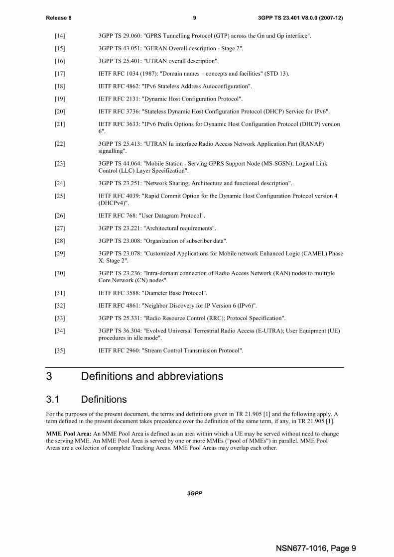
For the purposes of the present document, the terms and definitions given in TR 21.905 [1] and the following apply. Aterm defined in the present document takes precedence over the definition of the same term, if any, in TR 21.905 [1].
MME Pool Area: An MME Pool Area is defined as an area within which a UE may be served without need to changethe serving MME. An MME Pool Area is served by one or more MMEs ("pool of MMEs") in parallel. MME PoolAreas are a collection of complete Tracking Areas. MME Pool Areas may overlap each other.
NSN677-1016, Page 9
3GPP
3GPP TS 23.401 V8.0.0 (2007-12)10Release 8
Serving GW Service Area: A Serving GW Service Area is defined as an area within which a UE may be servedwithout need to change the Serving GW. A Serving GW Service Area is served by one or more Serving GWs inparallel. Serving GW Service Areas are a collection of complete Tracking Areas. Serving GW Service Areas mayoverlap each other.
3.2 Abbreviations
For the purposes of the present document, the abbreviations given in TR 21.905 [1] and the following apply. Anabbreviation defined in the present document takes precedence over the definition of the same abbreviation, if any, inTR 21.905 [1].
AMBR Aggregate Maximum Bit RateDL TFT DownLink Traffic Flow TemplateECM EPS Connection ManagementEMM EPS Mobility ManagementEPC Evolved Packet CoreEPS Evolved Packet SystemGUMMEI Globally Unique MME IdentifierGUTI Globally Unique Temporary IdentityGW GatewayPDB Packet Delay BudgetPLR Packet Loss RateLBI Linked EPS Bearer IdMME Mobility Management EntityMMEC MME CodeM-TMSI M-Temporary Mobile Subscriber IdentityP-GW PDN GatewayPTI Protocol Transaction IdS-GW Serving GatewayS-TMSI S-Temporary Mobile Subscriber IdentitySDF Service Data FlowTAC Tracking Area CodeTAI Tracking Area IdentityTAU Tracking Area UpdateUL TFT UpLink Traffic Flow Template
NSN677-1016, Page 10
3GPP
3GPP TS 23.401 V8.0.0 (2007-12)11Release 8
4 Architecture model and concepts
4.1 General concepts
Local breakout of IP traffic via the visited PLMN is supported, when network policies and user subscription allow it.Local breakout may be combined with support for multiple simultaneous PDN connections, described in clause 5.10.
4.2 Architecture reference model
4.2.1 Non-roaming architecture
SGi
S12
S3S1-MME
PCR
S7
S6a
HSS
Operator's IP Services(e.g. IMS, PSS etc.)
Rx+
S10
UE
SGSN
"LTE-Uu"
E-UTRAN
MME
S11
S5ServingGateway
PDNGateway
S1-U
S4
UTRAN
GERAN
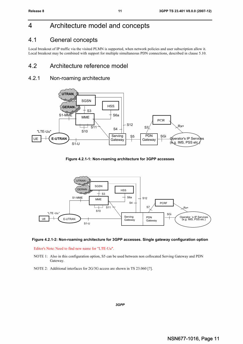
Figure 4.2.1-1: Non-roaming architecture for 3GPP accesses
SGi
S12
S3
S1-MME
PCRF
S7
S6a
HSS
Operator ’s IP Services(e.g. IMS, PSS etc.)
Rx+
UE
GERANSGSN
“LTE -Uu ”
E-UTRAN
MME
S11
S1-U
ServingGateway
PDNGateway
S10
UTRAN
S4
Figure 4.2.1-2: Non-roaming architecture for 3GPP accesses. Single gateway configuration option
Editor's Note: Need to find new name for "LTE-Uu".
NOTE 1: Also in this configuration option, S5 can be used between non collocated Serving Gateway and PDNGateway.
NOTE 2: Additional interfaces for 2G/3G access are shown in TS 23.060 [7].
NSN677-1016, Page 11
3GPP
3GPP TS 23.401 V8.0.0 (2007-12)12Release 8
4.2.2 Roaming architecture
S6a
HSS
S8a
S3
S1-MME
S10
UTRAN
GERAN
SGSN
MME
S11
ServingGateway
UE
“LTE -Uu”
E-UTRAN
S12
HPLMN
VPLMN
PCRF
S7 Rx+
SGi Operator’s IPServices
(e.g. IMS, PSS etc.)
PDNGateway
S1-U
S4
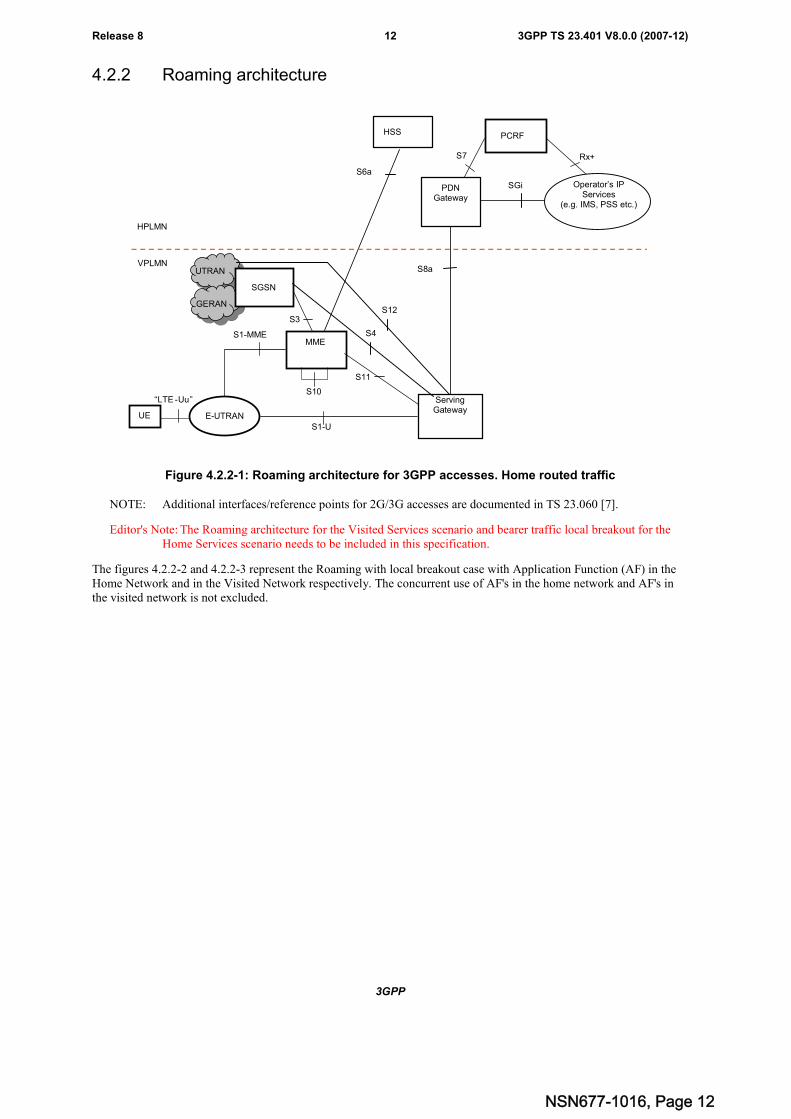
Figure 4.2.2-1: Roaming architecture for 3GPP accesses. Home routed traffic
NOTE: Additional interfaces/reference points for 2G/3G accesses are documented in TS 23.060 [7].
Editor's Note: The Roaming architecture for the Visited Services scenario and bearer traffic local breakout for theHome Services scenario needs to be included in this specification.
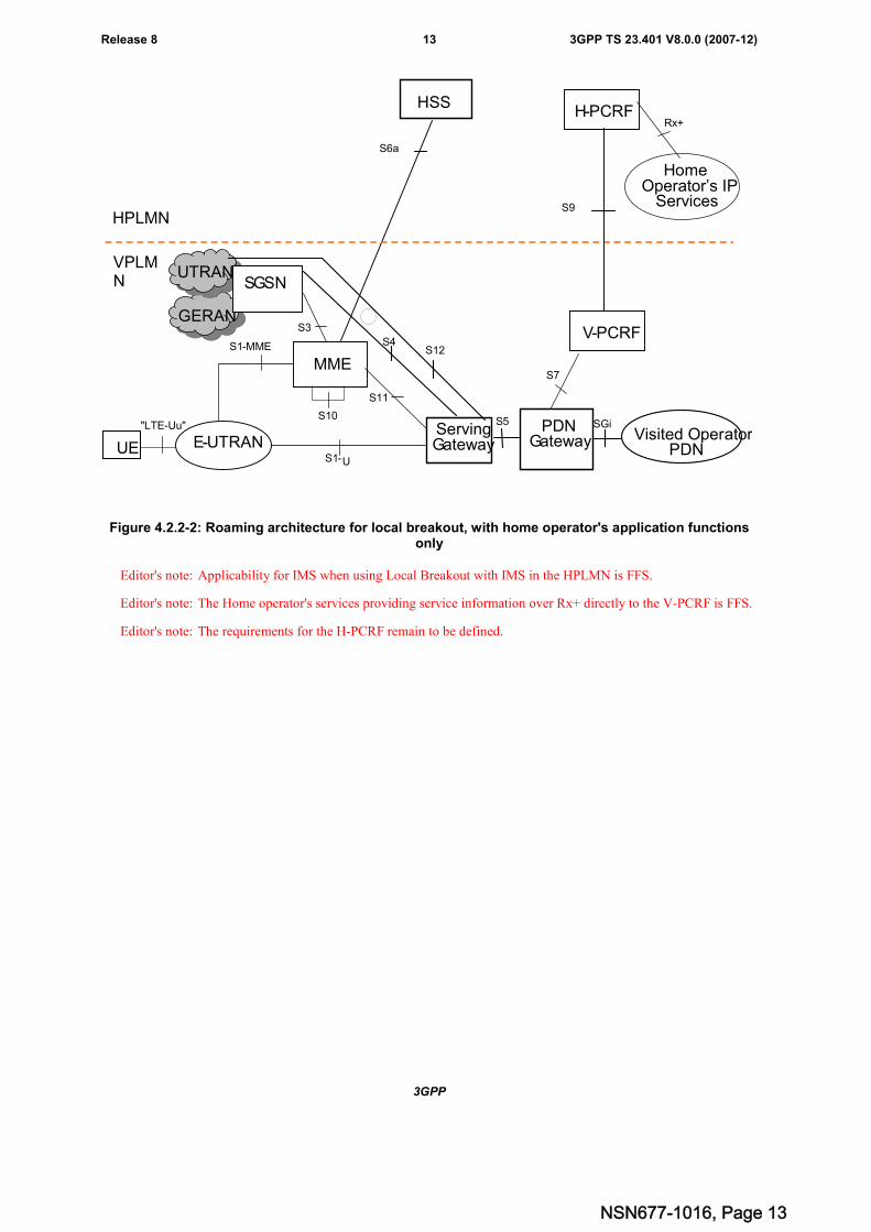
The figures 4.2.2-2 and 4.2.2-3 represent the Roaming with local breakout case with Application Function (AF) in theHome Network and in the Visited Network respectively. The concurrent use of AF's in the home network and AF's inthe visited network is not excluded.
NSN677-1016, Page 12
3GPP
3GPP TS 23.401 V8.0.0 (2007-12)13Release 8
S6a
HSS
S5
S3
S1-MME
S10
GERAN
UTRANSGSN
MME
S11
ServingGatewayUE
"LTE-Uu"
E-UTRAN
S4
HPLMN
VPLMN
V-PCRF
S7
SGiPDNGateway
S1-U
H-PCRF
S9
HomeOperator’s IP
Services
Rx+
Visited OperatorPDN
S12
Figure 4.2.2-2: Roaming architecture for local breakout, with home operator's application functionsonly
Editor's note: Applicability for IMS when using Local Breakout with IMS in the HPLMN is FFS.
Editor's note: The Home operator's services providing service information over Rx+ directly to the V-PCRF is FFS.
Editor's note: The requirements for the H-PCRF remain to be defined.
NSN677-1016, Page 13
3GPP
3GPP TS 23.401 V8.0.0 (2007-12)14Release 8
S6a
HSS
S5
S3
S1-MME
S10
UTRANSGSN
MME
S11
ServingGatewayUE
“LTE-Uu”
E-UTRAN
S4
HPLMN
VPLMN
V-PCRF
S7
SGi
PDNGateway
S1-U
H-PCRF
S9
HomeOperator’s IP
Services
Rx+
GERAN
S12
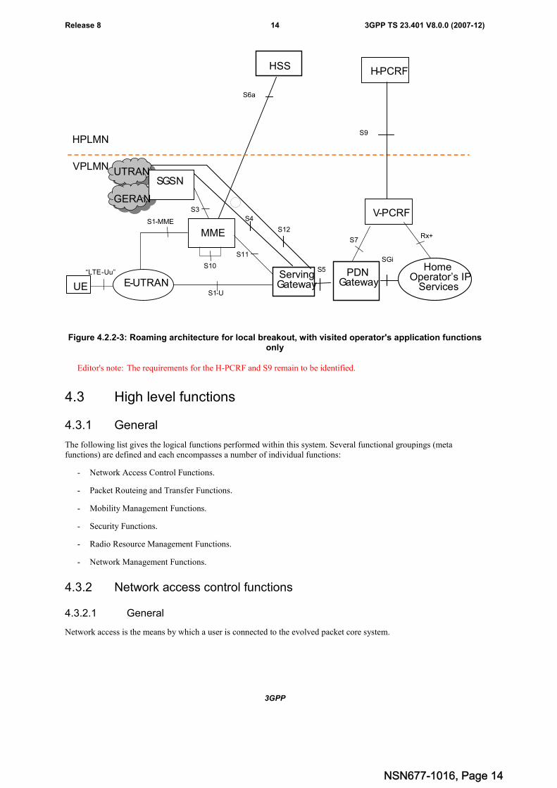
Figure 4.2.2-3: Roaming architecture for local breakout, with visited operator's application functionsonly
Editor's note: The requirements for the H-PCRF and S9 remain to be identified.
4.3 High level functions
4.3.1 General
The following list gives the logical functions performed within this system. Several functional groupings (metafunctions) are defined and each encompasses a number of individual functions:
- Network Access Control Functions.
- Packet Routeing and Transfer Functions.
- Mobility Management Functions.
- Security Functions.
- Radio Resource Management Functions.
- Network Management Functions.
4.3.2 Network access control functions
4.3.2.1 General
Network access is the means by which a user is connected to the evolved packet core system.
NSN677-1016, Page 14
3GPP
3GPP TS 23.401 V8.0.0 (2007-12)15Release 8
4.3.2.2 Network/Access network selection
It is the means by which a UE selects a PLMN/Access network from which to gain IP connectivity. The network/accessnetwork selection procedure varies for different access technologies. For 3GPP access networks, the network selectionprinciples are described in TS 23.122 [10]. For 3GPP access networks, the access network selection procedures aredescribed in TS 36.300 [5], TS 43.022 [11] and TS 25.304 [12].
Architectural impacts stemming from support for network/access network selection procedures for non-3GPP accessand between 3GPP access and non-3GPP accesses are described in TS 23.402 [2].
4.3.2.3 Authentication and authorisation function
This function performs the identification and authentication of the service requester, and the validation of the servicerequest type to ensure that the user is authorised to use the particular network services. The authentication function isperformed in association with the Mobility Management functions.
4.3.2.4 Admission control function
The purpose of admission control is to determine if the requested resources are available, and then reserve thoseresources.
4.3.2.5 Policy and Charging Enforcement Function
This includes all the functionality of PCEF as defined by TS 23.203 [6]. The PCEF encompasses service data flowdetection, policy enforcement and flow based charging functionalities as defined in TS 23.203 [6].
4.3.2.6 Lawful Interception
Lawful interception is the action, performed by a network operator / access provider / service provider, of makingavailable certain information and providing that information to a law enforcement monitoring facility.
4.3.3 Packet routeing and transfer functions
4.3.3.1 General
A route is an ordered list of nodes used for the transfer of packets within and between the PLMN(s). Each route consistsof the originating node, zero or more relay nodes and the destination node. Routeing is the process of determining andusing, in accordance with a set of rules, the route for transmission of a message within and between the PLMN(s).
The EPS is an IP network and uses the standard routeing and transport mechanism of underlying IP network.
Editor's note: The above text does not appear to be relevant to a functional description.
4.3.3.2 IP header compression function
The IP header compression function optimises use of radio capacity by IP header compression mechanisms.
4.3.3.3 Packet screening function
The packet screening function provides the network with the capability to check that the UE is using the exact IPv4-Address/IPv6-Prefix/Full-IPv6-Address that was assigned to the UE.
4.3.4 Security functions
4.3.4.1 Ciphering function
The ciphering function preserves the confidentiality of user data and signalling across the radio channels.
NSN677-1016, Page 15
3GPP
3GPP TS 23.401 V8.0.0 (2007-12)16Release 8
4.3.4.2 Integrity protection function
The integrity protection function ensures the integrity of the signalling between the UE and the network.
4.3.5 Mobility management functions
4.3.5.1 General
The mobility management functions are used to keep track of the current location of a UE.
4.3.5.2 Tracking and Reachability Management for UE in ECM-IDLE state
Tracking and Reachability Management comprises the functions to trace the location of a UE in ECM-IDLE state. Thelocation of a UE in ECM-IDLE state is known by the network on a Tracking Area List granularity. A UE in ECM-IDLEstate is paged in all cells of the Tracking Areas in which it is currently registered. The UE may be registered in multipleTracking Areas. A UE performs periodic Tracking Area Updates to ensure its reachability from the network.
4.3.5.3 Inter-eNodeB mobility anchor function
The Inter-eNodeB Mobility Anchor is the functional entity that anchors the user plane for E-UTRAN mobility.
4.3.5.4 Inter-3GPP mobility anchor function
The Inter-3GPP Mobility Anchor is the functional entity that anchors the user plane for mobility between 3GPP 2G/3Gaccess systems and the E-UTRA access system.
4.3.5.5 Idle mode signalling reduction function
The Idle mode Signalling Reduction function provides a mechanism to limit signalling during inter-RAT cell-reselection in idle mode (ECM-IDLE, PMM-IDLE, GPRS STANDBY states).
4.3.6 Radio Resource Management functions
Radio resource management functions are concerned with the allocation and maintenance of radio communicationpaths, and are performed by the radio access network. Refer to TS 36.300 [5] for further information on E-UTRAN.
4.3.7 Network management functions
4.3.7.1 General
Network management functions provide mechanisms to support O&M functions related to the Evolved System.
The Network management architecture and functions for the evolved packet core system are described in TS ss.xyz [qq]
4.3.6.2 Load balancing between MMEs
The MME Load Balancing functionality permits UEs that are entering into an MME Pool Area to be directed to anappropriate MME in a manner that achieves load balancing between MMEs.
The MME Load Re-balancing functionality permits UEs that are registered on an MME (within an MME Pool Area) tobe moved to another MME.
NOTE: An example use for the MME Load Re-balancing function is for the O+M related removal of one MMEfrom an MME Pool Area.
Editor's Note: Details of these functions need to be added.
NSN677-1016, Page 16
3GPP
3GPP TS 23.401 V8.0.0 (2007-12)17Release 8
4.3.8 Selection functions
4.3.8.1 PDN GW selection function (3GPP accesses)
The PDN GW selection function allocates a PDN GW that shall provide the PDN connectivity for the 3GPP access. Thefunction uses subscriber information provided by the HSS and possibly additional criteria. For each of the subscribedPDNs, the HSS provides:
- an IP address of a PDN GW and an APN, or
- an APN and an indication for this APN whether the allocation of a PDN GW from the visited PLMN is allowedor whether a PDN GW from the home PLMN shall be allocated.
Editor's note: It is FFS what additional criteria beyond the subscriber information can be used for PDN GWselection.
The HSS also indicates which of the subscribed PDNs is the default PDN for the UE.
To establish connectivity with a PDN when the UE is already connected to one or more PDNs, the UE provides therequested APN for the PDN GW selection function.
Editor's note: It is FFS whether the UE can provide upon initial attach additional input information (e.g. the desiredAPN) for the PDN GW selection function.
If the HSS provides an IP address of a PDN GW, no further PDN GW selection functionality is performed. Note thatthe provision of an IP address of a PDN GW as part of the subscriber information allows also for a PDN GW allocationby HSS.
If the HSS provides an APN of a PDN and the subscription allows for allocation of a PDN GW from the visited PLMNfor this APN, the PDN GW selection function derives a PDN GW address from the visited PLMN. If a visited PDN GWaddress cannot be derived, or if the subscription does not allow for allocation of a PDN GW from the visited PLMN,then the APN is used to derive a PDN GW address from the HPLMN. The PDN GW address is derived from the APN,subscription data and additional information by using the Domain Name Service function. If the APN-OI Replacementfield exists in the subscription data, the PDN GW domain name will be constructed by replacing the APN-OI with thevalue received in the APN-OI Replacement field. Otherwise, or when the resolution of the above PDN GW domainname fails, the PDN GW domain name will be constructed by appending '.mnc<MNC>.mcc<MCC>.gprs' as specifiedin Annex A of Pre-Rel-8 TS 23.060 [7] and TS 23.003 [9]. If the Domain Name Service function provides a list of PDNGW addresses, one PDN GW address is selected from this list. If the selected PDN GW cannot be used, e.g. due to anerror, then another PDN GW is selected from the list.
If the UE provides an APN for a PDN, this APN is then used to derive the PDN GW address as specified for the case ofHSS provided APN if the subscription allows for this APN.
As part of PDN GW selection, an IP address of the assigned PDN GW may be provided to the UE for use with hostbased mobility as defined in TS 23.402 [2], if the PDN GW supports host-based mobility for inter-access mobilitytowards accesses where host-based mobility can be used.
4.3.8.2 Serving GW selection function
The Serving GW selection function selects an available Serving GW to serve a UE. The selection bases on networktopology, i.e. the selected Serving GW serves the UE's location and in case of overlapping Serving GW service areas,the selection may prefer Serving GWs with service areas that reduce the probability of changing the Serving GW. Othercriteria for Serving GW selection should include load balancing between Serving GWs.
If a subscriber of a GTP only network roams into a PMIP network, the PDN GWs selected for local breakout supportthe PMIP protocol, while PDN GWs for home routed traffic use GTP. This means the Serving GW selected for suchsubscribers may need to support both GTP and PMIP, so that it is possible to set up both local breakout and homerouted sessions for these subscribers. For a Serving GW supporting both GTP and PMIP, the MME/SGSN shouldindicate the Serving GW which protocol should be used over S5/S8 interface.
If a subscriber of a GTP only network roams into a PMIP network, the PDN GWs selected for local breakout maysupport GTP or the subscriber may not be allowed to use PDN GWs of the visited network. In both cases a GTP onlybased Serving GW may be selected. These cases are considered as roaming between GTP based operators.
NSN677-1016, Page 17
3GPP
3GPP TS 23.401 V8.0.0 (2007-12)18Release 8
If combined Serving and PDN GWs are configured in the network the Serving GW Selection Function preferablyderives a Serving GW that is also a PDN GW for the UE.
The Domain Name Service function may be used to resolve a DNS string into a list of possible Serving GW addresseswhich serve the UE's location. The details of the selection are implementation specific.
Editor's note: In case of handover from non-3GPP accesses in roaming scenario, the serving GW selection functionfor local anchoring is described in TS 23.402.
4.3.8.3 MME selection function
The MME selection function selects an available MME for serving a UE. The selection is based on network topology,i.e. the selected MME serves the UE's location and in case of overlapping MME service areas, the selection may preferMMEs with service areas that reduce the probability of changing the MME. Other criteria for MME selection shouldinclude load balancing between MMEs.
4.3.8.4 SGSN selection function
The SGSN selection function selects an available SGSN to serve a UE. The selection is based on network topology, i.e.the selected SGSN serves the UE's location and in case of overlapping SGSN service areas, the selection may preferSGSNs with service areas that reduce the probability of changing the SGSN. Other criteria for SGSN selection may beload balancing between SGSNs.
4.3.8.5 Selection of PCRF
The PDN-GW and AF may be served by one or more PCRF nodes in the HPLMN and, in roaming with local breakoutscenarios, one or more PCRF nodes in the VPLMN.
The selection of PCRF and linking of the different UE's PCC sessions over the multiple PCRF interfaces (e.g. Rx+session, S7 session, S9 session etc.) for a UE IP CAN session is described in TS 23.203 [6].
4.3.9 IP network related functions
4.3.9.1 Domain Name Service function
The Domain Name Service function resolves logical PDN GW names to PDN GW addresses. This function is standardInternet functionality according to RFC 1034 [17], which allows resolution of any name to an IP address (or addresses)for PDN GWs and other nodes within the EPS.
4.3.9.2 DHCP function
The Dynamic Host Configuration Function allows to deliver IP configuration information for UEs. This function isstandard Internet functionality according to RFC 2131 [19], RFC 3736 [20], RFC 3633 [21] and RFC 4039 [25].
4.4 Network elements
4.4.1 E-UTRAN
E-UTRAN is described in more detail in TS 36.300 [5].
In addition to the E-UTRAN functions described in TS 36.300 [5], E-UTRAN functions include:
- Header compression and user plane ciphering;
- MME selection when no routeing to an MME can be determined from the information provided by the UE;
- UL bearer level rate enforcement based on AMBR and MBR(e.g. by limiting the amount of UL resources granted per UE over time);
- UL and DL bearer level admission control;
NSN677-1016, Page 18
3GPP
3GPP TS 23.401 V8.0.0 (2007-12)19Release 8
- Transport level packet marking in the uplink, e.g. setting the DiffServ Code Point, based on the QCI of theassociated EPS bearer.
4.4.2 MME
MME functions include:
- NAS signalling;
- NAS signalling security;
- Inter CN node signalling for mobility between 3GPP access networks (terminating S3);
- UE Reachability in ECM-IDLE state (including control and execution of paging retransmission);
- Tracking Area list management (for UE in idle and active mode);
- PDN GW and Serving GW selection;
- MME selection for handovers with MME change;
- SGSN selection for handovers to 2G or 3G 3GPP access networks;
- Roaming (S6a towards home HSS);
- Authentication;
- Bearer management functions including dedicated bearer establishment.
NOTE: The Serving GW and the MME may be implemented in one physical node or separated physical nodes.
4.4.3 Gateway
4.4.3.1 General
Two logical Gateways exist:
- Serving GW (S-GW);
- PDN GW (P-GW).
NOTE: The PDN GW and the Serving GW may be implemented in one physical node or separated physicalnodes.
4.4.3.2 Serving GW
The Serving GW is the gateway which terminates the interface towards E-UTRAN.
For each UE associated with the EPS, at a given point of time, there is a single Serving GW.
The functions of the Serving GW, for both the GTP-based and the PMIP-based S5/S8, include:
- the local Mobility Anchor point for inter-eNodeB handover;
- Mobility anchoring for inter-3GPP mobility (terminating S4 and relaying the traffic between 2G/3G system andPDN GW);
- ECM-IDLE mode downlink packet buffering and initiation of network triggered service request procedure;
- Lawful Interception;
- Packet routeing and forwarding;
- Transport level packet marking in the uplink and the downlink, e.g. setting the DiffServ Code Point, based on theQCI of the associated EPS bearer;
NSN677-1016, Page 19
3GPP
3GPP TS 23.401 V8.0.0 (2007-12)20Release 8
- Accounting on user and QCI granularity for inter-operator charging;
- UL and DL charging per UE, PDN, and QCI(e.g. for roaming with home routed traffic).
Additional Serving GW functions for the PMIP-based S5/S8 are captured in TS 23.402 [2].
4.4.3.3 PDN GW
The PDN GW is the gateway which terminates the SGi interface towards the PDN.
If a UE is accessing multiple PDNs, there may be more than one PDN GW for that UE.
PDN GW functions include for both the GTP-based and the PMIP-based S5/S8:
- Per-user based packet filtering (by e.g. deep packet inspection);
- Lawful Interception;
- UE IP address allocation;
- Transport level packet marking in the uplink and downlink, e.g. setting the DiffServ Code Point, based on theQCI of the associated EPS bearer;
- UL and DL service level charging as defined in TS 23.203 [6](e.g. based on SDFs defined by the PCRF, or based on deep packet inspection defined by local policy);
- UL and DL service level gating control as defined in TS 23.203 [6];
- UL and DL service level rate enforcement as defined in TS 23.203 [6](e.g. by rate policing/shaping per SDF);
- DL rate enforcement based on AMBR(e.g. by rate policing/shaping per aggregate of traffic of SDFs associated with Non-GBR QCIs);
- DL rate enforcement based on the accumulated MBRs of the aggregate of SDFs with the same GBR QCI(e.g. by rate policing/shaping);
- DHCPv4 and DHCPv6 functions (client, relay and server);
- The network does not support PPP bearer type in this version of the specification. Pre-Release 8 PPPfunctionality of a GGSN may be implemented in the PDN GW.
Additionally the PDN GW includes the following functions for the GTP-based S5/S8:
- UL and DL bearer binding as defined in TS 23.203 [6];
- UL bearer binding verification;
Editor's Note: This is to verify that the UE applies the UL packet filters correctly and does not misbehave, e.g., bysending packets on a "premium bearer" even though the packets do not match the UE's UL packet filtersassociated with that "premium bearer". Once the term 'UL bearer binding verification' has been defined inTS 23.203 this editor's note can be replaced with a corresponding reference.
- Functionality as defined in RFC 4861 [32].
4.4.4 SGSN
In addition to the functions described in TS 23.060 [7], SGSN functions include:
- Inter EPC node signalling for mobility between 2G/3G and E-UTRAN 3GPP access networks;
- PDN and Serving GW selection;
- MME selection for handovers to E-UTRAN 3GPP access network.
NSN677-1016, Page 20
3GPP
3GPP TS 23.401 V8.0.0 (2007-12)21Release 8
4.4.5 GERAN
GERAN is described in more detail in TS 43.051 [15].
4.4.6 UTRAN
UTRAN is described in more detail in TS 25.401 [16].
4.4.7 PCRF
4.4.7.1 General
PCRF is the policy and charging control element. PCRF functions are described in more detail in TS 23.203 [6].
In non-roaming scenario, there is only a single PCRF in the HPLMN associated with one UE's IP-CAN sessionThePCRF terminates the Rx+ interface and the S7 interface.
In a roaming scenario with local breakout of traffic there may be two PCRFs associated with one UE's IP-CAN session:
- H-PCRF that resides within the H-PLMN;
- V-PCRF that resides within the V-PLMN.
4.4.7.2 Home PCRF (H-PCRF)
The functions of the H-PCRF include:
- terminates the Rx+ reference point for home network services;
- terminates the S9 reference point for roaming with local breakout;
- associates the sessions established over the multiple reference points (S9, Rx+), for the same UE's IP-CANsession (PCC session binding).
The functionality of H-PCRF is described in TS 23.203 [6].
4.4.7.3 Visited PCRF (V-PCRF)
The functions of the V-PCRF include:
- terminates the S7 and S9 reference points for roaming with local breakout;
- terminates Rx+ for roaming with local breakout and visited operator's Application Function.
The functionality of V-PCRF is described in TS 23.203 [6].
4.5 Reference points
S1-MME:Reference point for the control plane protocol between E-UTRAN and MME.
S1-U: Reference point between E-UTRAN and Serving GW for the per bearer user plane tunnelling and intereNodeB path switching during handover.
S3: It enables user and bearer information exchange for inter 3GPP access network mobility in idle and/oractive state. It is based on Gn reference point as defined between SGSNs.
S4: It provides related control and mobility support between GPRS Core and the 3GPP Anchor function ofServing GW and is based on Gn reference point as defined between SGSN and GGSN. In addition, ifDirect Tunnel is not established, it provides the user plane tunnelling.
NSN677-1016, Page 21
3GPP
3GPP TS 23.401 V8.0.0 (2007-12)22Release 8
S5: It provides user plane tunneling and tunnel management between Serving GW and PDN GW. It is usedfor Serving GW relocation due to UE mobility and if the Serving GW needs to connect to a non-collocated PDN GW for the required PDN connectivity.
S6a: It enables transfer of subscription and authentication data for authenticating/authorizing user access to theevolved system (AAA interface) between MME and HSS.
S7: It provides transfer of (QoS) policy and charging rules from PCRF to Policy and Charging EnforcementFunction (PCEF) in the PDN GW. The interface is based on the Gx interface.
S8a: Inter-PLMN reference point providing user and control plane between the Serving GW in the VPLMNand the PDN GW in the HPLMN. It is based on Gp reference point as defined between SGSN and GGSN.S8a is the inter PLMN variant of S5.
S9: It provides transfer of (QoS) policy and charging control information between the Home PCRF and theVisited PCRF in order to support local breakout function.
S10: Reference point between MMEs for MME relocation and MME to MME information transfer.
S11: Reference point between MME and Serving GW.
S12: Reference point between UTRAN and Serving GW for user plane tunneling when Direct Tunnel isestablished. It is based on the Iu-u/Gn-u reference point using the GTP-U protocol as defined betweenSGSN and UTRAN or respectively between SGSN and GGSN. Usage of S12 is an operator configurationoption.
SGi: It is the reference point between the PDN GW and the packet data network. Packet data network may bean operator external public or private packet data network or an intra operator packet data network, e.g.for provision of IMS services. This reference point corresponds to Gi for 3GPP accesses.
Rx+ The Rx reference point resides between the AF and the PCRF in the TS 23.203 [6].
Editor's note: It is FFS if the Rx+ is significantly different from the Rel-7 Rx reference point to warrant defining itto be Rx+.
When data forwarding is used as part of mobility procedures different user plane routes may be used based on thenetwork configuration (e.g. direct or indirect data forwarding). These routes can be between eNodeB and RNC, eNodeBand SGSN, RNC and S-GW or between S-GW and SGSN. Explicit reference points are not defined for these routes.
Protocol assumption:
- The S1-U is based on GTP-U protocol;
- The S3 is based on GTP protocol;
- The S4 is based on GTP protocol;
- The S5 is based on GTP protocol. PMIP variant of S5 is described in TS 23.402 [2];
- The S8a is based on GTP protocol. PMIP variant of S8a (S8b) is described in TS 23.402 [2].
NOTE: Redundancy support on reference points S5 and S8a should be taken into account.
4.6 EPS Mobility Management and Connection Managementstates
Editor's note: The relationship and impact of the inter-system mobility to the EMM/ECM states are FFS. Thecurrent definitions of ECM-IDLE and ECM-CONNECTED states roughly correspond to PMM-IDLE andPMM-CONNECTED 3G-SGSN/UTRAN states.
4.6.1 General
The EPS Mobility Management (EMM) states describe the Mobility Management states that result from the mobilitymanagement procedures e.g. Attach and Tracking Area Update procedures.
NSN677-1016, Page 22
3GPP
3GPP TS 23.401 V8.0.0 (2007-12)23Release 8
The EPS Connection Management (ECM) states describe the signalling connectivity between the UE and the EPC.
The ECM and EMM states are independent of each other.
NOTE: For example, the UE has to be in the ECM-CONNECTED state in order for the network to send aTracking Area Update Reject message to the UE.
4.6.2 Definition of main EPS Mobility Management states
4.6.2.1 EMM-DEREGISTERED
In the EMM-DEREGISTERED state, the EMM context in MME holds no valid location or routeing information for theUE. The UE is not reachable by a MME, as the UE location is not known.
In the EMM-DEREGISTERED state, some UE context can still be stored in the UE and MME, e.g. to avoid running anAKA procedure during every Attach procedure.
4.6.2.2 EMM-REGISTERED
The UE enters the EMM-REGISTERED state by a successful registration procedure which is either an Attachprocedure or a Tracking Area Update procedure. In the EMM-REGISTERED state, the UE can receive services thatrequire registration in the EPS.
The UE location is known in the MME to at least an accuracy of the tracking area list allocated to that UE (excludingsome abnormal cases).
In the EMM-REGISTERED state, the UE shall:
- perform a tracking area update if the new TA is not in the list of TAs that the UE has received from the networkin order to maintain the registration and enable the MME to page the UE;
- perform the periodic tracking area updating procedure to notify the EPC that the UE is available;
- answer to paging from the MME by performing a service request procedure;
- perform the service request procedure in order to establish the radio bearers when uplink user data is to be sent.
After performing the Detach procedure, the state is changed to EMM-DEREGISTERED in the UE and in the MME.Upon receiving the TAU Reject and Attach Reject messages the actions of the UE and MME depend upon the 'causevalue' in the reject message, but, in many cases the state is changed to EMM-DEREGISTERED in the UE and in theMME.
The MME may perform an implicit detach any time after the UE reachable timer expires.
Editor's note: Interaction with UE reachable timer is FFS.
4.6.3 Definition of EPS Connection Management states
4.6.3.1 ECM-IDLE
A UE is in ECM-IDLE state when no NAS signalling connection between UE and network exists. In ECM-IDLE state,a UE performs cell selection/reselection according to TS 36.304 [34] and PLMN selection according to TS 23.122 [10].
There exists no UE context in E-UTRAN for the UE in the ECM-IDLE state. There is no S1_MME and no S1_Uconnection for the UE in the ECM-IDLE state.
The UE and the MME shall enter the ECM-CONNECTED state when the signalling connection is established betweenthe UE and the MME.
NSN677-1016, Page 23
3GPP
3GPP TS 23.401 V8.0.0 (2007-12)24Release 8
4.6.3.2 ECM-CONNECTED
The UE location is known in the MME with an accuracy of a cell ID. The mobility of UE is handled by the handoverprocedure. The UE performs the tracking area update procedure when TAI in the EMM system information is not in thelist of TA's that the UE is registered with the network.
For a UE in the ECM-CONNECTED state, there exists a signalling connection between the UE and the MME. Thesignalling connection is made up of two parts: an RRC connection and an S1_MME connection.
The S1 release procedure changes the state at both UE and MME from ECM-CONNECTED to ECM-IDLE.
NOTE: The UE may not receive the indication for the S1 release, e.g. due to radio link error or out of coverage.In this case, there can be temporal mismatch between the ECM-state in the UE and the ECM-state in theMME.
After a signalling procedure (e.g. tracking area update), the MME may decide to release the signalling connection to theUE, after which the state at both the UE and the MME is changed to ECM-IDLE.
Editor's note: There are some error cases where the UE also changes to EMM-IDLE. The details are FFS.
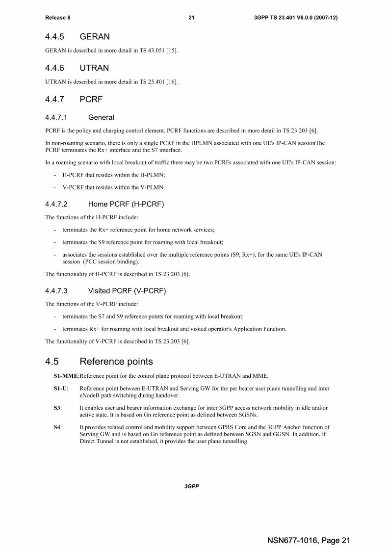
4.6.4 State transition and functions
EMM-DEREGISTERED EMM-REGISTERED
Attach accept,TAU accept
Detach,Attach Reject,TAU reject
Figure 4.6.4-1: EMM state model in UE
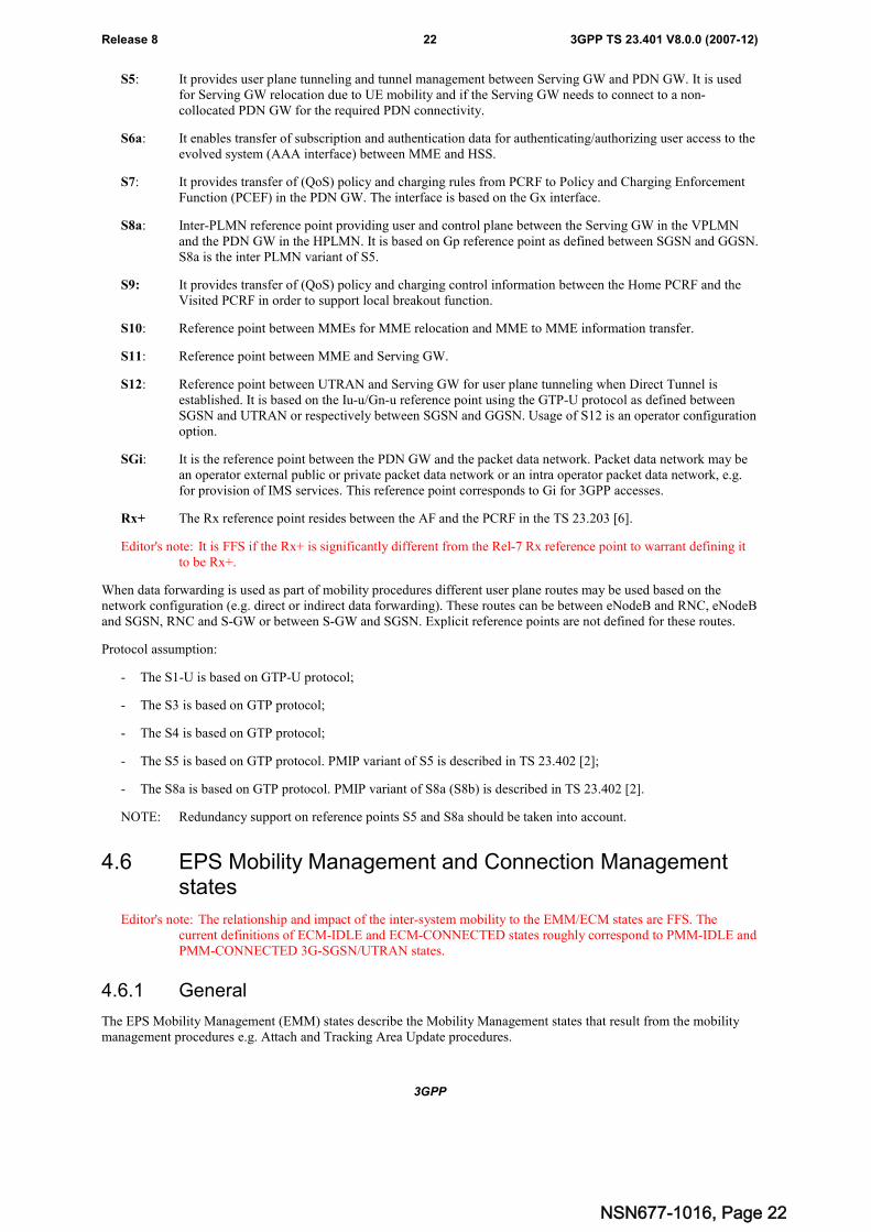
EMM-DEREGISTERED EMM-REGISTERED
Attach accept,TAU accept
Detach,Attach Reject,TAU reject
Figure 4.6.4-2: EMM state model in MME
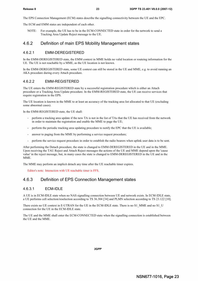
ECM-IDLE ECM-CONNECTED
RRC connectionestablished
RRC connectionreleased
Figure 4.6.4-3: ECM state model in UE
NSN677-1016, Page 24
3GPP
3GPP TS 23.401 V8.0.0 (2007-12)25Release 8
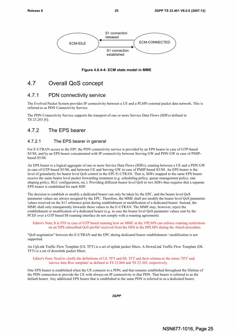
ECM-IDLE ECM-CONNECTED
S1 connectionestablished
S1 connectionreleased
Figure 4.6.4-4: ECM state model in MME
4.7 Overall QoS concept
4.7.1 PDN connectivity service
The Evolved Packet System provides IP connectivity between a UE and a PLMN external packet data network. This isreferred to as PDN Connectivity Service.
The PDN Connectivity Service supports the transport of one or more Service Data Flows (SDFs) defined inTS 23.203 [6].
4.7.2 The EPS bearer
4.7.2.1 The EPS bearer in general
For E-UTRAN access to the EPC the PDN connectivity service is provided by an EPS bearer in case of GTP-basedS5/S8, and by an EPS bearer concatenated with IP connectivity between Serving GW and PDN GW in case of PMIP-based S5/S8.
An EPS bearer is a logical aggregate of one or more Service Data Flows (SDFs), running between a UE and a PDN GWin case of GTP-based S5/S8, and between UE and Serving GW in case of PMIP-based S5/S8. An EPS bearer is thelevel of granularity for bearer level QoS control in the EPC/E-UTRAN. That is, SDFs mapped to the same EPS bearerreceive the same bearer level packet forwarding treatment (e.g. scheduling policy, queue management policy, rateshaping policy, RLC configuration, etc.). Providing different bearer level QoS to two SDFs thus requires that a separateEPS bearer is established for each SDF.
The decision to establish or modify a dedicated bearer can only be taken by the EPC, and the bearer level QoSparameter values are always assigned by the EPC. Therefore, the MME shall not modify the bearer level QoS parametervalues received on the S11 reference point during establishment or modification of a dedicated bearer. Instead, theMME shall only transparently forwards those values to the E-UTRAN. The MME may, however, reject theestablishment or modification of a dedicated bearer (e.g. in case the bearer level QoS parameter values sent by thePCEF over a GTP based S8 roaming interface do not comply with a roaming agreement).
Editor's Note: It is FFS in case of GTP based roaming how an MME in the VPLMN can enforce roaming restrictionson an 'EPS subscribed QoS profile' received from the HSS in the HPLMN during the Attach procedure.
"QoS negotiation" between the E-UTRAN and the EPC during dedicated bearer establishment / modification is notsupported.
An UpLink Traffic Flow Template (UL TFT) is a set of uplink packet filters. A DownLink Traffic Flow Template (DLTFT) is a set of downlink packet filters.
Editor's Note: Need to clarify the definitions of UL TFT and DL TFT and their relation to the terms 'TFT' and'service data flow template' as defined in TS 23.060 and TS 23.203, respectively.
One EPS bearer is established when the UE connects to a PDN, and that remains established throughout the lifetime ofthe PDN connection to provide the UE with always-on IP connectivity to that PDN. That bearer is referred to as thedefault bearer. Any additional EPS bearer that is established to the same PDN is referred to as a dedicated bearer.
NSN677-1016, Page 25
3GPP
3GPP TS 23.401 V8.0.0 (2007-12)26Release 8
Every EPS bearer is associated with an UL TFT in the UE and a DL TFT in the PCEF.
NOTE: The evaluation precedence order of the filters associated with the default bearer, in relation to thoseassociated with the dedicated bearers, is up to operator configuration. However, if the default bearer isintended to be used for all traffic that doesn't match any of the filters associated to dedicated bearersand/or it is associated with a "match all" filter, then operators should assure that the filters associated withthe default bearer are assigned the lowest evaluation precedence order of all filters within that IP-CANsession. Any other configuration would effectively exclude the dedicated bearers associated with filters oflower precedence order from being used, and should therefore be considered a mis-configuration in thisparticular context.
The initial bearer level QoS parameter values of the default bearer are assigned by the network, based on subscriptiondata (in case of E-UTRAN the MME sets those initial values based on subscription data retrieved from HSS). ThePCEF may change those values based in interaction with the PCRF or based on local configuration.
NOTE: In case of 3GPP access: if PCC is enabled the MME should not verify bearer level QoS parameter valuesreceived on the S11 reference point against any subscription data stored in HSS. This is independent ofwhether a bearer is a default or a dedicated bearer.
The distinction between default and dedicated bearers should be transparent to the access network (e.g. E-UTRAN).
An EPS bearer is referred to as a GBR bearer if dedicated network resources related to a Guaranteed Bit Rate (GBR)value that is associated with the EPS bearer are permanently allocated (e.g. by an admission control function in theeNodeB) at bearer establishment/modification. Otherwise, an EPS bearer is referred to as a Non-GBR bearer.
NOTE: Admission control can be performed at establishment / modification of a Non-GBR bearer even though aNon-GBR bearer is not associated with a GBR value.
A dedicated bearer can either be a GBR or a Non-GBR bearer. A default bearer shall be a Non-GBR bearer.
NOTE: A default bearer remains permanently established to provide the UE with always-on IP connectivity to acertain PDN. That motivates the restriction of a default bearer to bearer type Non-GBR.
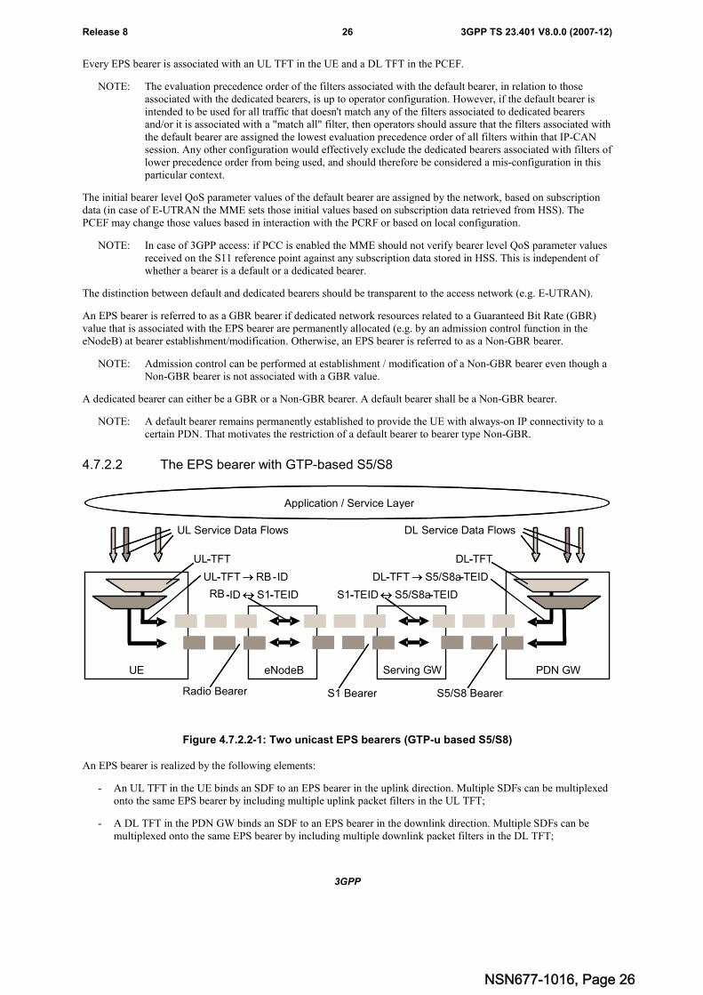
4.7.2.2 The EPS bearer with GTP-based S5/S8
Serving GW PDN GWeNB
Radio Bearer S5/S8 Bearer
Application / Service Layer
UL-TFT RB-ID
DL Service Data Flows
DL-TFT
DL-TFT S5/S8a-TEID
RB-ID S1-TEID
S1 Bearer
S1-TEID S5/S8a-TEID
UE
UL Service Data Flows
UL-TFT
Serving GW PDN GWeNodeB
-
-
- -
- - - -
UE
-
Figure 4.7.2.2-1: Two unicast EPS bearers (GTP-u based S5/S8)
An EPS bearer is realized by the following elements:
- An UL TFT in the UE binds an SDF to an EPS bearer in the uplink direction. Multiple SDFs can be multiplexedonto the same EPS bearer by including multiple uplink packet filters in the UL TFT;
- A DL TFT in the PDN GW binds an SDF to an EPS bearer in the downlink direction. Multiple SDFs can bemultiplexed onto the same EPS bearer by including multiple downlink packet filters in the DL TFT;
NSN677-1016, Page 26
3GPP
3GPP TS 23.401 V8.0.0 (2007-12)27Release 8
- A radio bearer (defined in TS 36.300 [5]) transports the packets of an EPS bearer between a UE and an eNodeB.There is a one-to-one mapping between an EPS bearer and a radio bearer;
- An S1 bearer transports the packets of an EPS bearer between an eNodeB and a Serving GW;
- An S5/S8 bearer transports the packets of an EPS bearer between a Serving GW and a PDN GW;
- A UE stores a mapping between an uplink packet filter and a radio to create the binding between an SDF and aradio bearer in the uplink;
- A PDN GW stores a mapping between a downlink packet filter and an S5/S8a bearer to create the bindingbetween an SDF and an S5/S8a bearer in the downlink;
- An eNodeB stores a one-to-one mapping between a radio bearer and an S1 to create the binding between a radiobearer and an S1 bearer in both the uplink and downlink;
- A Serving GW stores a one-to-one mapping between an S1 bearer and an S5/S8a bearer to create the bindingbetween an S1 bearer and an S5/S8a bearer in both the uplink and downlink.
4.7.2.3 The EPS bearer with PMIP-based S5/S8
See clause 4.6 in TS 23.402 [2].
4.7.3 Bearer level QoS parameters
The bearer level (i.e. per bearer or per bearer aggregate) QoS parameters are QCI, ARP, GBR, MBR, and AMBRdescribed in this section.
Each EPS bearer (GBR and Non-GBR) is associated with the following bearer level QoS parameters:
- QoS Class Identifier (QCI);
- Allocation and Retention Priority (ARP).
A QCI is a scalar that is used as a reference to access node-specific parameters that control bearer level packetforwarding treatment (e.g. scheduling weights, admission thresholds, queue management thresholds, link layer protocolconfiguration, etc.), and that have been pre-configured by the operator owning the access node (e.g. eNodeB). A one-to-one mapping of standardized QCI values to standardized characteristics is captured in Annex B.
NOTE 1: On the radio interface and on S1, each PDU (e.g. RLC PDU or GTP-u PDU) is indirectly associated withone QCI via the bearer identifier carried in the PDU header. The same applies to the S5 and S8 interfacesif they are based on GTP-u.
The primary purpose of ARP is to decide whether a bearer establishment / modification request can be accepted orneeds to be rejected in case of resource limitations (typically available radio capacity in case of GBR bearers). Inaddition, the ARP can be used (e.g. by the eNodeB) to decide which bearer(s) to drop during exceptional resourcelimitations (e.g. at handover). Once successfully established, a bearer's ARP shall not have any impact on the bearerlevel packet forwarding treatment (e.g. scheduling and rate control). Such packet forwarding treatment should be solelydetermined by the other bearer level QoS parameters: QCI, GBR, MBR, and AMBR.
NOTE 2: The ARP should be understood as "Priority of Allocation and Retention"; not as "Allocation, Retention,and Priority". A more precise definition of ARP, e.g. the encoding of 'retention', is left FFS.
Each GBR bearer is additionally associated with the following bearer level QoS parameters:
- Guaranteed Bit Rate (GBR);
- Maximum Bit Rate (MBR).
The GBR denotes the bit rate that can be expected to be provided by a GBR bearer. The MBR limits the bit rate that canbe expected to be provided by a GBR bearer (e.g. excess traffic may get discarded by a rate shaping function). TheMBR may be greater than or equal to GBR for a particular GBR bearer.
Editor's note: Whether a Non-GBR bearer may also be associated with an MBR is FFS.
NSN677-1016, Page 27
3GPP
3GPP TS 23.401 V8.0.0 (2007-12)28Release 8
Editor's note: Rate-adaptation schemes are FFS.
Each PDN connection (i.e. IP address) is associated with the following IP-CAN session level QoS parameter:
- Aggregate Maximum Bit Rate (AMBR).
Multiple EPS bearers of the same PDN connection can share the same AMBR. That is, each of those EPS bearers couldpotentially utilize the entire AMBR, e.g. when the other EPS bearers do not carry any traffic. The AMBR limits theaggregate bit rate that can be expected to be provided by the EPS bearers sharing the AMBR (e.g. excess traffic may getdiscarded by a rate shaping function). AMBR applies to all Non-GBR bearers belonging to the same PDN connection.GBR bearers are outside the scope of AMBR.
The GBR and MBR denote bit rates of traffic per bearer while AMBR denotes a bit rate of traffic per group of bearers.Each of those three bearer level QoS parameters has an uplink and a downlink component. On S1_MME the values ofthe GBR, MBR, and AMBR refer to the bit stream excluding the GTP-u header overhead on S1_U.
Editor's note: A more precise definition of GBR, MBR, and AMBR, e.g. whether those parameters only denote a bitrate or additionally also a token bucket size, is left FFS.
One 'EPS subscribed QoS profile' is defined for each APN permitted for the subscriber. It contains the bearer level QoSparameter values for that APN's default bearer (QCI and ARP) and that APN's AMBR.
NOTE: Subscription data related to bearer level QoS parameter values for dedicated bearers is specified inTS 23.203 [6].
4.7.4 Application of PCC in the Evolved Packet System
The Evolved Packet System applies the PCC framework as defined in TS 23.203 [6] for QoS policy and chargingcontrol. PCC functionality is present in the AF, PCEF and PCRF.
An EPS needs to support both PCEF and PCRF functionality to enable dynamic policy and charging control by meansof installation of PCC rules based on user and service dimensions. However, an EPS may only support PCEFfunctionality in which case it shall support static policy and charging control.
NOTE: The local configuration of PCEF static policy and charging control functionality is not subject tostandardization. The PCEF static policy and control functionality is not based on subscriptioninformation.
The following applies to the use of dynamic policy and charging control in EPS:
- The service level (per SDF) QoS parameters are conveyed in PCC rules (one PCC rule per SDF) over the S7reference point. The service level QoS parameters consist of a QoS Class Identifier (QCI) Allocation andRetention Priority (ARP) and authorised Guaranteed and Maximum Bit Rate values for uplink and downlink.The QCI is a scalar that represents the QoS characteristics that the EPS is expected to provide for the SDF. ARPis an indicator of the priority of allocation and retention for the SDF. The service level ARP assigned by PCRFin a PCC rule may be different from the bearer level ARP stored in subscription data;
- The set of standardized QCIs and their characteristics that the PCRF in an EPS can select from is provided inAnnex B, table B-1. It is expected that the PCRF selects a QCI in such a way that the IP-CAN receiving it cansupport it;
- It is not required that an IP-CAN supports all standardized QCIs;
- For local breakout, the visited network has the capability to reject the QoS authorized by the home networkbased on operator policies.
The following applies regardless of whether dynamic or static policy and charging control is used in EPS:
- For E-UTRAN the value of the ARP of an EPS bearer is identical to the value of the ARP of the SDF(s) mappedto that EPS bearer;
- For the same UE/PDN connection: SDFs associated with different QCIs or with the same service-level QCI butdifferent ARP shall not be mapped to the same EPS bearer;
NSN677-1016, Page 28
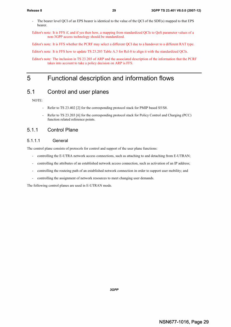
3GPP
3GPP TS 23.401 V8.0.0 (2007-12)29Release 8
- The bearer level QCI of an EPS bearer is identical to the value of the QCI of the SDF(s) mapped to that EPSbearer.
Editor's note: It is FFS if, and if yes then how, a mapping from standardized QCIs to QoS parameter values of anon-3GPP access technology should be standardized.
Editor's note: It is FFS whether the PCRF may select a different QCI due to a handover to a different RAT type.
Editor's note: It is FFS how to update TS 23.203 Table A.3 for Rel-8 to align it with the standardized QCIs.
Editor's note: The inclusion in TS 23.203 of ARP and the associated description of the information that the PCRFtakes into account to take a policy decision on ARP is FFS.
5 Functional description and information flows
5.1 Control and user planes
NOTE:
- Refer to TS 23.402 [2] for the corresponding protocol stack for PMIP based S5/S8.
- Refer to TS 23.203 [6] for the corresponding protocol stack for Policy Control and Charging (PCC)function related reference points.
5.1.1 Control Plane
5.1.1.1 General
The control plane consists of protocols for control and support of the user plane functions:
- controlling the E-UTRA network access connections, such as attaching to and detaching from E-UTRAN;
- controlling the attributes of an established network access connection, such as activation of an IP address;
- controlling the routeing path of an established network connection in order to support user mobility; and
- controlling the assignment of network resources to meet changing user demands.
The following control planes are used in E-UTRAN mode.
NSN677-1016, Page 29
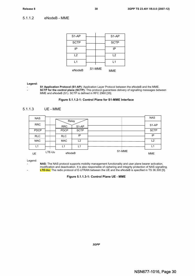
3GPP
3GPP TS 23.401 V8.0.0 (2007-12)30Release 8
5.1.1.2 eNodeB - MME
SCTP
L2
L1
IP
L2
L1
IP
SCTP
S1-MMEeNodeB MME
S1-AP S1-AP
Legend:- S1 Application Protocol (S1-AP): Application Layer Protocol between the eNodeB and the MME.- SCTP for the control plane (SCTP): This protocol guarantees delivery of signalling messages between
MME and eNodeB (S1). SCTP is defined in RFC 2960 [35].
Figure 5.1.1.2-1: Control Plane for S1-MME Interface
5.1.1.3 UE - MME
SCTP
L2
L1
IP
L2
L1
IP
SCTP
S1-MMEeNodeB MME
S1-AP S1-AP
NAS
MAC
L1
RLC
PDCP
UE
RRC
MAC
L1
RLC
PDCP
RRC
LTE-Uu
NASRelay
Legend:- NAS: The NAS protocol supports mobility management functionality and user plane bearer activation,
modification and deactivation. It is also responsible of ciphering and integrity protection of NAS signalling.- LTE-Uu: The radio protocol of E-UTRAN between the UE and the eNodeB is specified in TS 36.300 [5].
Figure 5.1.1.3-1: Control Plane UE - MME
NSN677-1016, Page 30
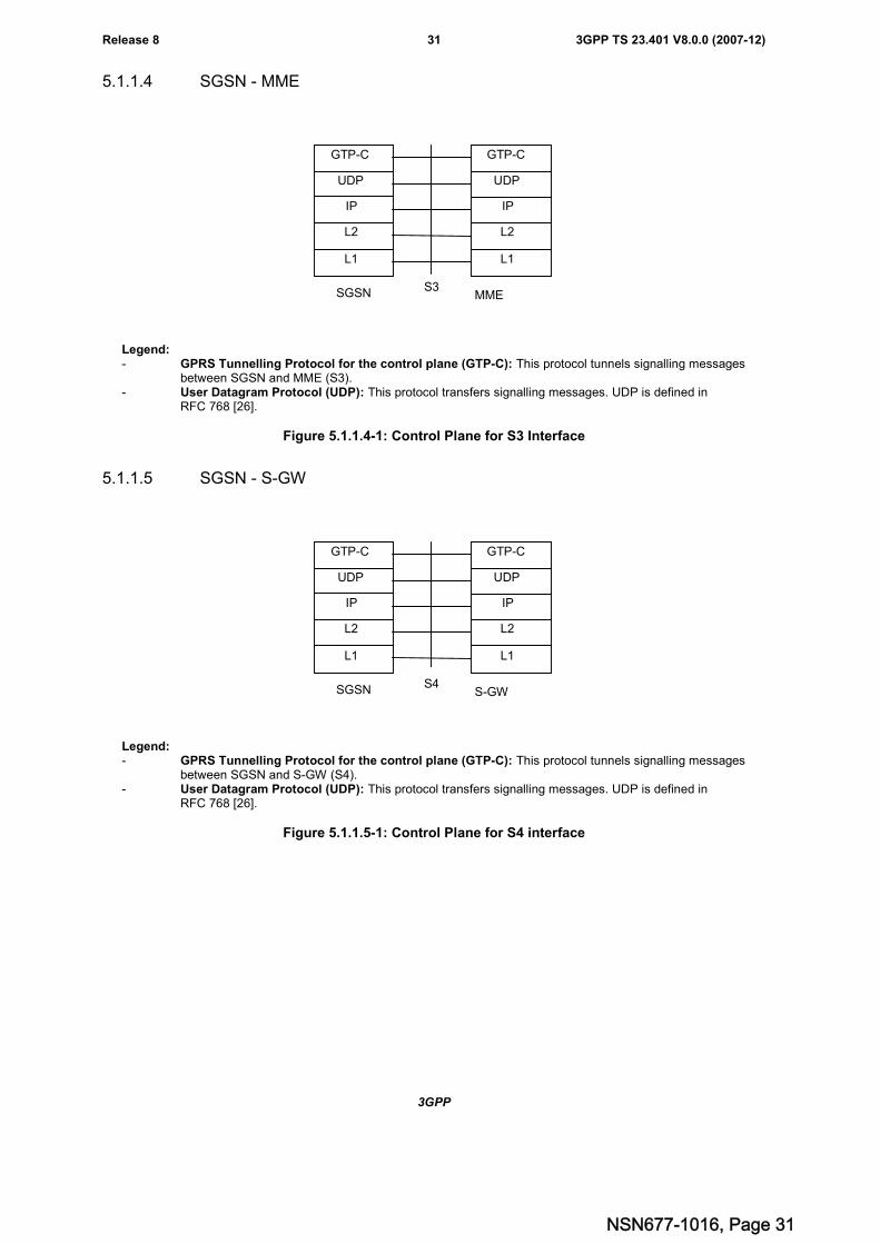
3GPP
3GPP TS 23.401 V8.0.0 (2007-12)31Release 8
5.1.1.4 SGSN - MME
UDP
L2
L1
IP
L2
L1
IP
UDP
S3SGSN MME
GTP-C GTP-C
Legend:- GPRS Tunnelling Protocol for the control plane (GTP-C): This protocol tunnels signalling messages
between SGSN and MME (S3).- User Datagram Protocol (UDP): This protocol transfers signalling messages. UDP is defined in
RFC 768 [26].
Figure 5.1.1.4-1: Control Plane for S3 Interface
5.1.1.5 SGSN - S-GW
UDP
L2
L1
IP
L2
L1
IP
UDP
S4SGSN S-GW
GTP-C GTP-C
Legend:- GPRS Tunnelling Protocol for the control plane (GTP-C): This protocol tunnels signalling messages
between SGSN and S-GW (S4).- User Datagram Protocol (UDP): This protocol transfers signalling messages. UDP is defined in
RFC 768 [26].
Figure 5.1.1.5-1: Control Plane for S4 interface
NSN677-1016, Page 31
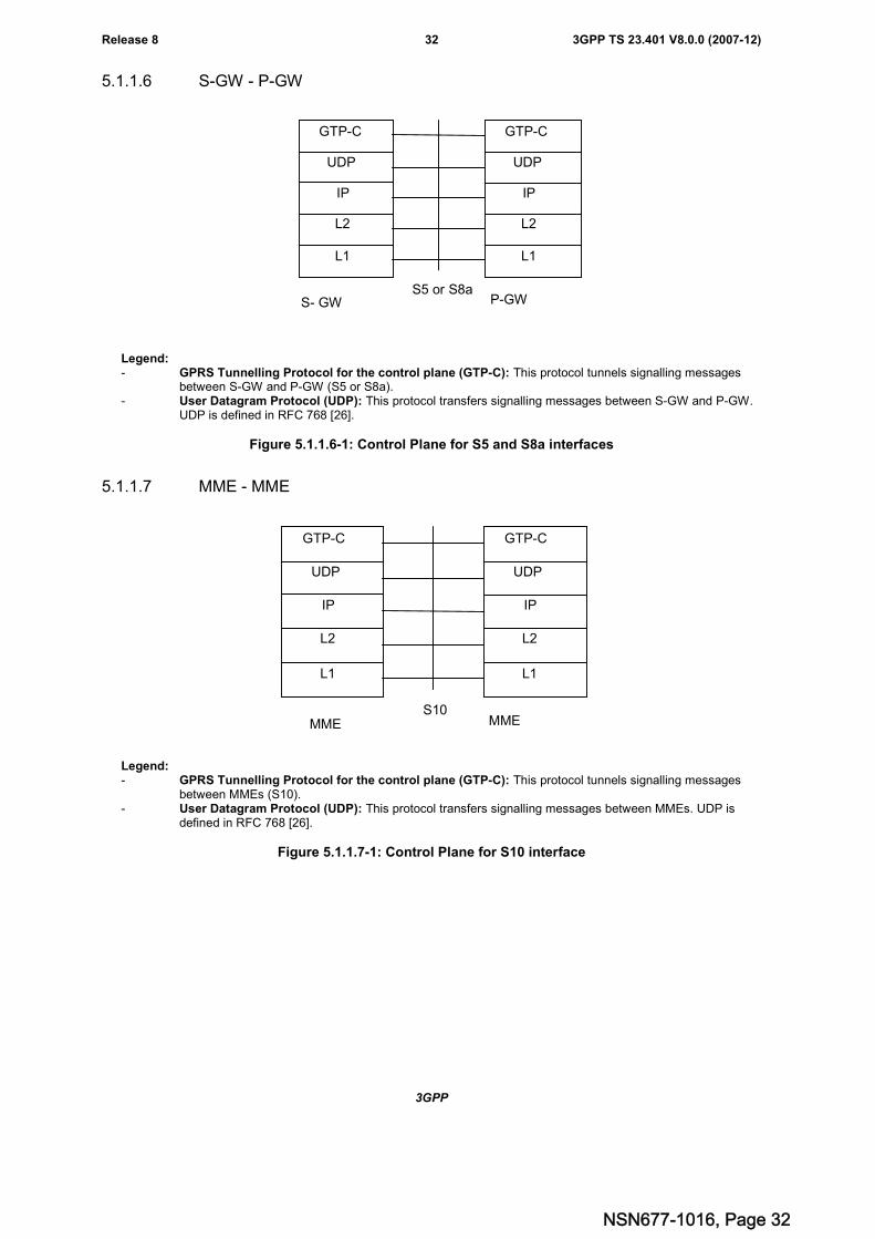
3GPP
3GPP TS 23.401 V8.0.0 (2007-12)32Release 8
5.1.1.6 S-GW - P-GW
UDP
L2
L1
IP
L2
L1
IP
UDP
S5 or S8aS- GW P-GW
GTP-C GTP-C
Legend:- GPRS Tunnelling Protocol for the control plane (GTP-C): This protocol tunnels signalling messages
between S-GW and P-GW (S5 or S8a).- User Datagram Protocol (UDP): This protocol transfers signalling messages between S-GW and P-GW.
UDP is defined in RFC 768 [26].
Figure 5.1.1.6-1: Control Plane for S5 and S8a interfaces
5.1.1.7 MME - MME
UDP
L2
L1
IP
L2
L1
IP
UDP
S10MME MME
GTP-C GTP-C
Legend:- GPRS Tunnelling Protocol for the control plane (GTP-C): This protocol tunnels signalling messages
between MMEs (S10).- User Datagram Protocol (UDP): This protocol transfers signalling messages between MMEs. UDP is
defined in RFC 768 [26].
Figure 5.1.1.7-1: Control Plane for S10 interface
NSN677-1016, Page 32
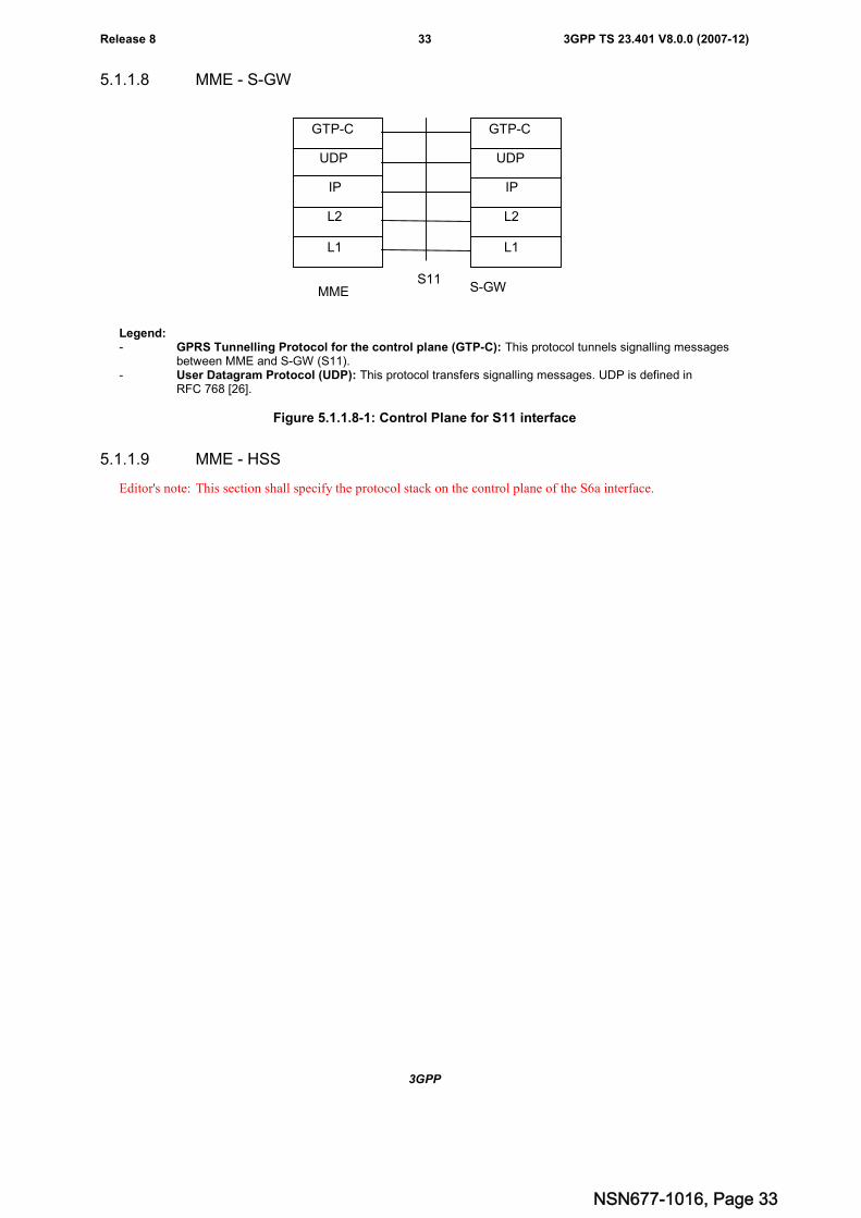
3GPP
3GPP TS 23.401 V8.0.0 (2007-12)33Release 8
5.1.1.8 MME - S-GW
UDP
L2
L1
IP
L2
L1
IP
UDP
S11MME S-GW
GTP-C GTP-C
Legend:- GPRS Tunnelling Protocol for the control plane (GTP-C): This protocol tunnels signalling messages
between MME and S-GW (S11).- User Datagram Protocol (UDP): This protocol transfers signalling messages. UDP is defined in
RFC 768 [26].
Figure 5.1.1.8-1: Control Plane for S11 interface
5.1.1.9 MME - HSS
Editor's note: This section shall specify the protocol stack on the control plane of the S6a interface.
NSN677-1016, Page 33
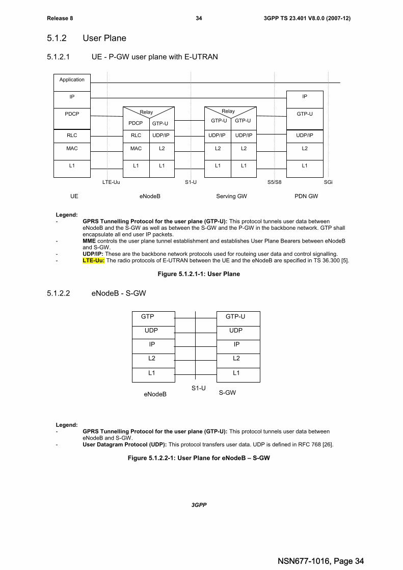
3GPP
3GPP TS 23.401 V8.0.0 (2007-12)34Release 8
5.1.2 User Plane
5.1.2.1 UE - P-GW user plane with E-UTRAN
Serving GW PDN GW
S5/S8a
GTP-UGTP-U
UDP/IP UDP/IP
L2
Relay
L2
L1 L1
PDCP
RLC
MAC
L1
IP
Application
UDP/IP
L2
L1
GTP-U
IP
SGiS1-ULTE-Uu
eNodeB
RLC UDP/IP
L2
PDCP GTP-U
Relay
MAC
L1 L1
UE
Legend:- GPRS Tunnelling Protocol for the user plane (GTP-U): This protocol tunnels user data between
eNodeB and the S-GW as well as between the S-GW and the P-GW in the backbone network. GTP shallencapsulate all end user IP packets.
- MME controls the user plane tunnel establishment and establishes User Plane Bearers between eNodeBand S-GW.
- UDP/IP: These are the backbone network protocols used for routeing user data and control signalling.- LTE-Uu: The radio protocols of E-UTRAN between the UE and the eNodeB are specified in TS 36.300 [5].
Figure 5.1.2.1-1: User Plane
5.1.2.2 eNodeB - S-GW
UDP
L2
L1
IP
L2
L1
IP
UDP
S1-UeNodeB S-GW
GTP GTP-U
Legend:- GPRS Tunnelling Protocol for the user plane (GTP-U): This protocol tunnels user data between
eNodeB and S-GW.- User Datagram Protocol (UDP): This protocol transfers user data. UDP is defined in RFC 768 [26].
Figure 5.1.2.2-1: User Plane for eNodeB – S-GW
NSN677-1016, Page 34
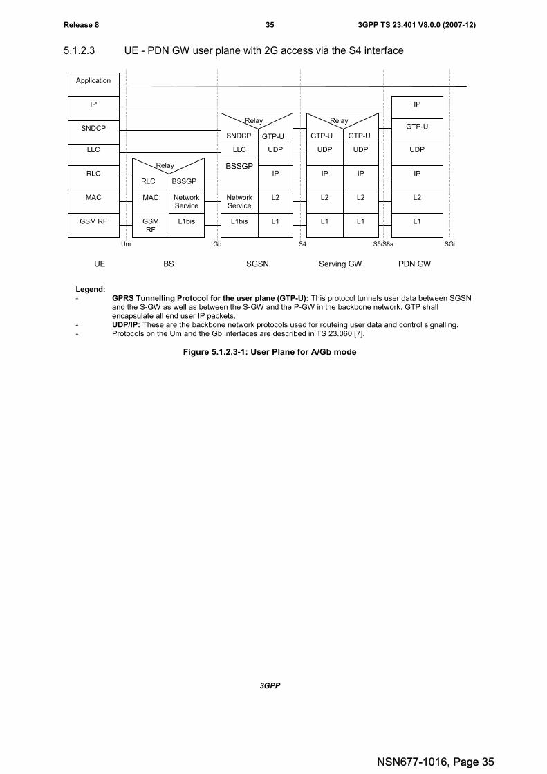
3GPP
3GPP TS 23.401 V8.0.0 (2007-12)35Release 8
5.1.2.3 UE - PDN GW user plane with 2G access via the S4 interface
Serving GW PDN GW
S5/S8a
MAC
GSMRF
NetworkService
L1bis
RLC BSSGP
Relay
LLC
BSSGPIP
L2
SNDCP GTP-U
Relay
NetworkService
L1bis L1
UDP
GTP-UGTP-U
UDP
IP IP
L2
Relay
L2
L1 L1
LLC
RLC
MAC
GSM RF
SNDCP
IP
Application
IP
L2
L1
UDP
IP
SGiS4GbUm
SGSNBSUE
UDP
GTP-U
Legend:- GPRS Tunnelling Protocol for the user plane (GTP-U): This protocol tunnels user data between SGSN
and the S-GW as well as between the S-GW and the P-GW in the backbone network. GTP shallencapsulate all end user IP packets.
- UDP/IP: These are the backbone network protocols used for routeing user data and control signalling.- Protocols on the Um and the Gb interfaces are described in TS 23.060 [7].
Figure 5.1.2.3-1: User Plane for A/Gb mode
NSN677-1016, Page 35
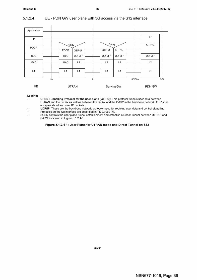
3GPP
3GPP TS 23.401 V8.0.0 (2007-12)36Release 8
5.1.2.4 UE - PDN GW user plane with 3G access via the S12 interface
Serving GW PDN GW
S5/S8a
GTP-UGTP-U
UDP/IP UDP/IP
L2
Relay
L2
L1 L1
PDCP
RLC
MAC
L1
IP
Application
UDP/IP
L2
L1
GTP-U
IP
SGiIuUu
UTRAN
RLC UDP/IP
L2
PDCP GTP-U
Relay
MAC
L1 L1
UE
Legend:- GPRS Tunnelling Protocol for the user plane (GTP-U): This protocol tunnels user data between
UTRAN and the S-GW as well as between the S-GW and the P-GW in the backbone network. GTP shallencapsulate all end user IP packets.
- UDP/IP: These are the backbone network protocols used for routeing user data and control signalling.- Protocols on the Uu interface are described in TS 23.060 [7].- SGSN controls the user plane tunnel establishment and establish a Direct Tunnel between UTRAN and
S-GW as shown in Figure 5.1.2.4-1.
Figure 5.1.2.4-1: User Plane for UTRAN mode and Direct Tunnel on S12
NSN677-1016, Page 36
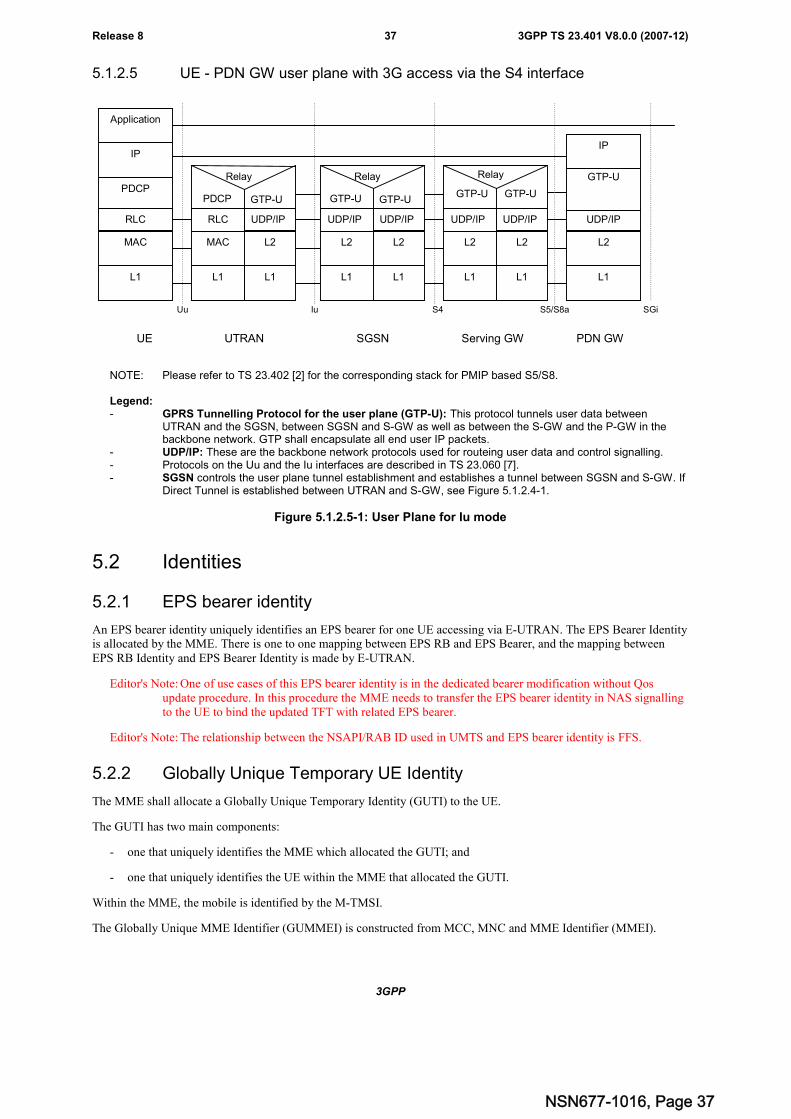
3GPP
3GPP TS 23.401 V8.0.0 (2007-12)37Release 8
5.1.2.5 UE - PDN GW user plane with 3G access via the S4 interface
Serving GW PDN GW
S5/S8a
UDP/IP UDP/IP
L2
GTP-U GTP-U
Relay
L2
L1 L1
GTP-UGTP-U
UDP/IP UDP/IP
L2
Relay
L2
L1 L1
PDCP
RLC
MAC
L1
IP
Application
UDP/IP
L2
L1
GTP-U
IP
SGiS4IuUu
SGSNUTRANUE
RLC UDP/IP
L2
PDCP GTP-U
Relay
MAC
L1 L1
NOTE: Please refer to TS 23.402 [2] for the corresponding stack for PMIP based S5/S8.
Legend:- GPRS Tunnelling Protocol for the user plane (GTP-U): This protocol tunnels user data between
UTRAN and the SGSN, between SGSN and S-GW as well as between the S-GW and the P-GW in thebackbone network. GTP shall encapsulate all end user IP packets.
- UDP/IP: These are the backbone network protocols used for routeing user data and control signalling.- Protocols on the Uu and the Iu interfaces are described in TS 23.060 [7].- SGSN controls the user plane tunnel establishment and establishes a tunnel between SGSN and S-GW. If
Direct Tunnel is established between UTRAN and S-GW, see Figure 5.1.2.4-1.
Figure 5.1.2.5-1: User Plane for Iu mode
5.2 Identities
5.2.1 EPS bearer identity
An EPS bearer identity uniquely identifies an EPS bearer for one UE accessing via E-UTRAN. The EPS Bearer Identityis allocated by the MME. There is one to one mapping between EPS RB and EPS Bearer, and the mapping betweenEPS RB Identity and EPS Bearer Identity is made by E-UTRAN.
Editor's Note: One of use cases of this EPS bearer identity is in the dedicated bearer modification without Qosupdate procedure. In this procedure the MME needs to transfer the EPS bearer identity in NAS signallingto the UE to bind the updated TFT with related EPS bearer.
Editor's Note: The relationship between the NSAPI/RAB ID used in UMTS and EPS bearer identity is FFS.
5.2.2 Globally Unique Temporary UE Identity
The MME shall allocate a Globally Unique Temporary Identity (GUTI) to the UE.
The GUTI has two main components:
- one that uniquely identifies the MME which allocated the GUTI; and
- one that uniquely identifies the UE within the MME that allocated the GUTI.
Within the MME, the mobile is identified by the M-TMSI.
The Globally Unique MME Identifier (GUMMEI) is constructed from MCC, MNC and MME Identifier (MMEI).
NSN677-1016, Page 37
3GPP
3GPP TS 23.401 V8.0.0 (2007-12)38Release 8
In turn the MMEI is constructed from an MME Group ID (MMEGI) and an MME Code (MMEC).
The GUTI is constructed from the GUMMEI and the M-TMSI.
For paging, the mobile is paged with the S-TMSI. The S-TMSI is constructed from the MMEC and the M-TMSI.
The operator needs to ensure that the MMEC is unique within the MME pool area and, if overlapping pool areas are inuse, unique within the area of overlapping MME pools.
The GUTI is used to support subscriber identity confidentiality, and, in the shortened S-TMSI form, to enable moreefficient radio signalling procedures (e.g. paging and Service Request).
5.2.3 Tracking Area Identity (TAI)
This is the identity used to identify tracking areas. The Tracking Area Identity is constructed from the MCC (MobileCountry Code), MNC (Mobile Network Code) and TAC (Tracking Area Code).
NOTE: Changes in the TAI of a cell can occur but are normally infrequent and linked with O+M activity.
5.2.4 eNodeB S1-AP UE Identity (eNB S1-AP UE ID)
This is the temporary identity used to identify a UE on the S1-MME reference point within the eNodeB. It is uniquewithin the eNodeB per S1-MME reference point instance.
5.2.5 MME S1-AP UE Identity (MME S1-AP UE ID)
This is the temporary identity used to identify a UE on the S1-MME reference point within the MME. It is uniquewithin the MME per S1-MME reference point instance.
5.3 Authentication, security and location management
5.3.1 IP address allocation
5.3.1.1 General
A UE shall perform the address allocation procedures for at least one IP address (either IPv4 or IPv6) after the defaultbearer activation if no IPv4 address is allocated during the default bearer activation.
One of the following ways shall be used to allocate IP addresses for the UE:
a) The HPLMN allocates the IP address to the UE when the default bearer is activated (dynamic or static HPLMNaddress);
b) The VPLMN allocates the IP address to the UE when the default bearer is activated (dynamic VPLMN address);or
c) The PDN operator or administrator allocates an (dynamic or static) IP address to the UE when the default beareris activated (External PDN Address Allocation).
The IP address allocated for the UE's default bearer shall also be used for the UE's dedicated bearers towards the samePDN. The IP address allocation for the multiple PDN GW case is handled with the same set of mechanisms as Attach.
One EPS bearer supports dual-stack IP addressing, meaning that it is able to transport both native IPv4 and native IPv6packets. Single address bearer types (IPv4, IPv6) are not specified in the EPS bearer model.
Editor's note: During handovers involving a Rel-8 SGSN, EPS bearers are mapped one-to-one to PDP contexts. TheEPS Bearer Identity will have the equivalent value as the NSAPI. A Rel-8 UE, which supports dual-stackaddressing, shall be able to transfer both IPv4 and IPv6 payload on one PDP context whilst in theUTRAN/GERAN. It is FFS how interactions with pre-Rel-8 2G/3G systems are handled.
NSN677-1016, Page 38
3GPP
3GPP TS 23.401 V8.0.0 (2007-12)39Release 8
It is the HPLMN operator that shall define in the subscription whether a dynamic HPLMN or VPLMN address may beused.
All the IP address allocation mechanisms presented below as well as the IP address allocation being part of the NASattach procedure is optional for the UE. The mechanism supported is UE product dependent.
The mechanism used to allocate IPv4 address(es) to a UE depends on the UE's and the network capabilities. Unlike2G/3G systems, in EPS UE may also indicate to the network within the PDN Address Allocation information elementhow the UE wants to obtain the IPv4 address:
- the UE may indicate that it prefers to obtain an IPv4 address as part of the default bearer activation procedure. Insuch a case, the UE relies on the EPS network to provide IPv4 address to the UE as part of the default beareractivation procedure.
- the UE may indicate that it prefers to obtain the IPv4 address after the default bearer setup by executing IETFprocedures. That is, the EPS network does not provide the IPv4 address for the UE as part of the default beareractivation procedures. The network may respond to the UE by leaving the relevant field empty or simply bysetting it to 0.0.0.0. After the default bearer establishment procedure is completed, the UE uses the connectivitywith the EPS and initiates the IPv4 address allocation on its own using DHCPv4. The UE sends DHCPv4Discover message (see details in sub-clause 5.3.1.2.4).
NOTE: For legacy terminals where the UE is not capable to send such an indication the EPS network selects theIPv4 address allocation method based on its policy.
EPS shall support the following mechanisms
a. IPv4 address allocation via default bearer activation.
EPS shall also support the following mechanisms following the attach procedure:
a. /64 IPv6 prefix allocation via IPv6 Stateless Address autoconfiguration according to RFC 4862 [18];
b. IPv4 address allocation and IPv4 parameter configuration via DHCPv4 according to RFC 2131 [19] andRFC 4039 [25];
c. IPv6 parameter configuration via Stateless DHCPv6 according to RFC 3736 [20].
If requested by the UE, the EPS may allocate a shorter than /64 IPv6 prefix delegation via DHCPv6 according toRFC 3633 [21].
The following clauses describe how the above listed IP address allocation mechanisms work when GTP based S5/S8 isused. The way of working of the IP address allocation mechanisms for PMIP based S5/S8 can be found inTS 23.402 [2].The procedures can be used both for PLMN (VPLMN/HPLMN) or external PDN based IP addressallocation. Note it is transparent to the UE whether the PLMN or the external PDN allocates the IP address.
Editor's note: The placement of DHCP relay and server entities is FFS.
Editor's note: It is FFS if additional security measures need to be taken in the case of DHCPv4 and DHCPv6.
IPv6 Stateless Address autoconfiguration [18] is the basic mechanism to allocate /64 IPv6 prefix to the UE.Alternatively shorter than /64 IPv6 prefix delegation via DHCPv6, RFC 3633 [21] may be provided, if it is supported bythe PDN-GW. When DHCPv6 prefix delegation is not supported the UE should use stateless address autoconfigurationRFC 4862 [18].
During the attach procedure and default bearer establishment, the PDN GW sends the IPv6 prefix and InterfaceIdentifier to the SGW, and then the S-GW forwards the IPv6 prefix and Interface Identifier to the MME or to the SGSN.The MME or the SGSN forwards the IPv6 Interface Identifier to the UE.
Editor's note: It is a stage 3 matter if the MME or the Rel-8 SGSN forwards the whole IPv6 address or only theInterface Identifier to the UE. Even if the UE receives the IPv6 prefix in the Attach Accept message, itshall ignore it.
NSN677-1016, Page 39
3GPP
3GPP TS 23.401 V8.0.0 (2007-12)40Release 8
5.3.1.2 IP address allocation mechanisms for GTP based S5/S8
5.3.1.2.1 IPv4 address allocation via default bearer activation
In this case the IP address is provided to the UE as part of the default bearer activation.
When the PLMN allocates the IP address then it is the PDN-GW responsibility to allocate and release the IP address,e.g. the PDN GW can use an internal address pool.
When the IP address is allocated from the external PDN, it is the PDN GW's responsibility to obtain and release the IPaddress. The PDN GW can use either DHCPv4 or RADIUS or Diameter to request the IP address for the UE from theexternal PDN. If DHCPv4 is used, the PDN GW functions as the DHCPv4 Client. If RADIUS is used, the PDN GWfunctions as the RADIUS Client. If Diameter is used, the PDN GW functions as the Diameter Client.
5.3.1.2.2 IPv6 prefix allocation via IPv6 stateless address autoconfiguration
When the PLMN allocates the IPv6 prefix then it is the PDN GW responsibility to allocate and release the IPv6 prefix,e.g. the PDN GW can use an internal address pool.
When the IPv6 prefix is allocated from the external PDN, it is the PDN GW responsibility to obtain and release theIPv6 prefix address. The PDN GW can use either DHCPv6 or RADIUS or Diameter to request the IPv6 prefix for theUE from the external PDN. If DHCPv6 is used, the PDN-GW functions as the DHCPv6 Client. If RADIUS is used, thePDN GW functions as the RADIUS Client. If Diameter is used, the PDN GW functions as the Diameter Client.
The procedure of the stateless IPv6 address autoconfiguration is the following: After the attach procedure and defaultbearer establishment, the UE may send a Router Solicitation message to the PDN GW to activate the sending of theRouter Advertisement message. The PDN-GW sends a Router Advertisement message. The Router Advertisementmessages shall contain the same prefix as the one provided during the attach procedure, if provided.
Editor's note: It is FFS if the PDN GW needs to send the IPv6 prefix to the MME/SGSN via S-GWin the CreateDefault Bearer Response and to the UE in the Attach Accept message. This is used to inform theMME/SGSN of the IPv6 prefix allocated to the UE. The UE shall ignore the prefix included in the AttachAccept message.
Editor's note: It is FFS if the PDN GW can include more than one prefix in a Router Advertisement.
After the UE has received the Router Advertisement message, it constructs its full IPv6 address via IPv6 StatelessAddress autoconfiguration. The UE may change the interface identifier used to generate full IPv6 addresses, withoutinvolving the network.
Any prefix that the PDN GW advertises to the UE is unique. The PDN GW shall also record the relationship betweenUE identities and the allocated IPv6 prefix. Because any prefix that the PDN GW advertises to the UE is unique, thereis no need for the UE to perform Duplicate Address Detection for any IPv6 address configured from the allocated IPv6prefix. However, the PDN GW shall provide a Neighbor Advertisement when receiving Neighbor Solicitationmessages. For example, it is possible for the UE to perform Neighbor Unreachability Detection towards the PDN GW,as defined in RFC 2461 [32].
5.3.1.2.3 IPv6 parameter configuration via stateless DHCPv6
The UE may use stateless DHCPv6 for additional parameter configuration. When PLMN based address allocation isused the PDN GW acts as DHCPv6 server. When external PDN allocation is used the PDN GW can act either as aDHCPv6 server or as a DHCPv6 relay agent.
5.3.1.2.4 IPv4 address allocation and IPv4 parameter configuration via DHCPv4
When the PLMN allocates the IPv4 address then the PDN GW responsibility is to allocate and release the IPv4 address(as it is in the previous case) and the PDN GW shall act as DHCPv4 server and shall create and send the DHCPv4responses to the UE.
When external PDN allocation is used the PDN GW shall act as a DHCPv4 relay agent and forward the DHCP requestsand responses between the UE and the DHCP server located in the external PDN.
NSN677-1016, Page 40
3GPP
3GPP TS 23.401 V8.0.0 (2007-12)41Release 8
5.3.1.2.5 IPv6 prefix delegation via DHCPv6
When the PLMN allocates the IPv6 prefix then the PDN GW responsibility is to allocate and release the IPv6 prefixes(as it is in the previous case) and the PDN GW shall act as DHCPv6 server and shall create and send the DHCPv6responses to the UE.
When external PDN allocation is used the PDN GW shall act as a DHCPv6 relay agent and forward the DHCP requestsand responses between the UE and the DHCP server located in the external PDN.
5.3.2 Attach procedure
5.3.2.1 E-UTRAN Initial Attach
A UE/user needs to register with the network to receive services that require registration. This registration is describedas Network Attachment. The always-on IP connectivity for UE/users of the EPS is enabled by establishing a defaultEPS bearer during Network Attachment. The PCC rules applied to the default EPS bearer may be predefined in thePDN GW and activated in the attachment by the PDN GW itself. The Attach procedure may trigger one or multipleDedicated Bearer Establishment procedures to establish dedicated EPS bearer(s) for that UE. During the attachprocedure, the UE may request for an IP address allocation. Terminals utilising only IETF based mechanisms for IPaddress allocation are also supported.
During the [Power-on (FFS)] Initial Attach procedure the Mobile Equipment Identity is obtained from the UE. TheMME operator may check the ME Identity with an EIR. At least in roaming situations, the MME should pass the MEIdentity to the HSS, and, if a PDN-GW outside of the VPLMN, should pass the ME Identity to the PDN-GW.
The Attach procedure shall also be used when a UE is already Attached over GERAN/UTRAN, but has no PDP contextestablished, and performs access change to E-UTRAN.
NSN677-1016, Page 41
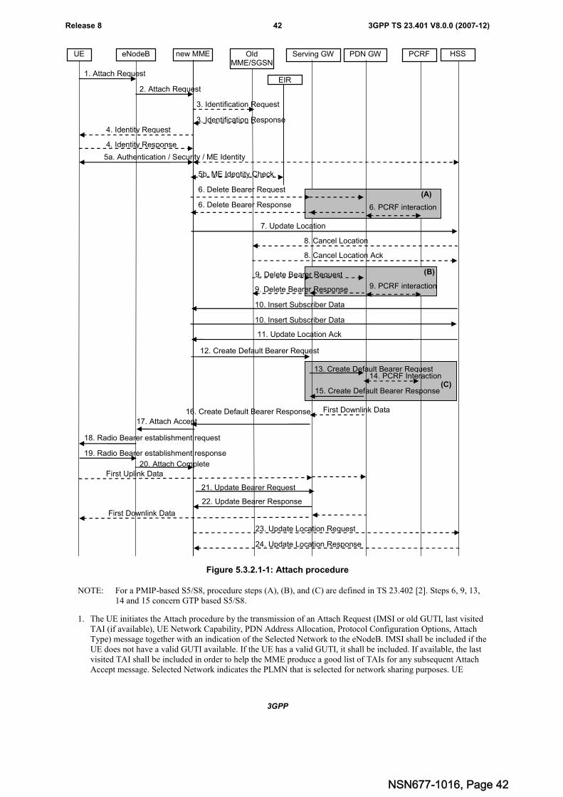
3GPP
3GPP TS 23.401 V8.0.0 (2007-12)42Release 8
3. Identification Request
1. Attach Request
new MME OldMME/SGSN
Serving GW PCRF HSS
3. Identification Response
PDN GW
2. Attach Request
eNodeBUE
4. Identity Request
4. Identity Response
5a. Authentication / Security / ME Identity
17. Attach Accept
First Uplink Data
19. Radio Bearer establishment response
18. Radio Bearer establishment request
20. Attach Complete
22. Update Bearer Response
21. Update Bearer Request
First Downlink Data
23. Update Location Request
24. Update Location Response
(B)
(A)
16. Create Default Bearer Response
12. Create Default Bearer Request
7. Update Location
8. Cancel Location
11. Update Location Ack
8. Cancel Location Ack
9. Delete Bearer Request
9. Delete Bearer Response
13. Create Default Bearer Request
15. Create Default Bearer Response
6. Delete Bearer Response
6. Delete Bearer Request
10. Insert Subscriber Data
10. Insert Subscriber Data
14. PCRF Interaction
First Downlink Data
(C)
EIR
5b. ME Identity Check
6. PCRF interaction
9. PCRF interaction
Figure 5.3.2.1-1: Attach procedure
NOTE: For a PMIP-based S5/S8, procedure steps (A), (B), and (C) are defined in TS 23.402 [2]. Steps 6, 9, 13,14 and 15 concern GTP based S5/S8.
1. The UE initiates the Attach procedure by the transmission of an Attach Request (IMSI or old GUTI, last visitedTAI (if available), UE Network Capability, PDN Address Allocation, Protocol Configuration Options, AttachType) message together with an indication of the Selected Network to the eNodeB. IMSI shall be included if theUE does not have a valid GUTI available. If the UE has a valid GUTI, it shall be included. If available, the lastvisited TAI shall be included in order to help the MME produce a good list of TAIs for any subsequent AttachAccept message. Selected Network indicates the PLMN that is selected for network sharing purposes. UE
NSN677-1016, Page 42
3GPP
3GPP TS 23.401 V8.0.0 (2007-12)43Release 8
Network Capability is described in clause "UE capabilities". If a NAS security association between the UE andthe MME already exists, the Attach Request message shall be integrity protected in order to allow validation ofthe UE by the MME. It is FFS if the Attach Request message, or any individual information elements included init, may also be encrypted to ensure its confidentiality. The PDN Address Allocation indicates whether the UEwants to perform the IP address allocation during the attach procedure and, when known, it indicates the UE IPversion capability (IPv4, IPv4/IPv6, IPv6), which is the capability of the IP stack associated with the UE.Protocol Configuration Options (PCO) are used to transfer parameters between the UE and the PDN GW, andare sent transparently through the MME and the Serving GW. Attach Type indicates "Handover" when the UEhas already an activated PDN GW/HA due to mobility with non-3GPP accesses.
Editor's note: It has yet to be determined whether message 1 is only sent in ECM-CONNECTED state (e.g. it ispreceded by a Service Request (type=signalling) procedure), or, whether message 1 can be used toestablish an S1 connection (in which case, the message needs to carry the S-TMSI).
Editor's note: The eNodeB may need to read GUTI/IMSI or other information elements from NAS message (e.g. toderive MME routeing), therefore it is assumed that at least these parts of that message are not encrypted.
Editor's note: It's assumed that all the radio capabilities of the UE that the eNodeB has to know in order to handleradio resources for this UE are send to eNodeB upon RRC connection establishment.
Editor's note: It's FFS whether the other values of the PDN Address Allocation and related use should beconsidered.
2. The eNodeB derives the MME from the GUTI and from the indicated Selected Network. If that MME is notassociated with the eNodeB, the eNodeB selects an MME as described in clause 4.3.8.3 on "MME selectionfunction". The eNodeB forwards the Attach Request message to the new MME contained in a S1-MME controlmessage (Initial UE message) together with the Selected Network and an indication of the E-UTRAN Areaidentity, a globally unique E-UTRAN ID of the cell from where it received the message to the new MME.
3. If the UE identifies itself with GUTI and the MME has changed since detach, the new MME sends anIdentification Request (old GUTI) to the old MME to request the IMSI. If the S-TMSI and old TAI identifies anSGSN, the message shall be sent to the old SGSN. The old MME/SGSN responds with Identification Response(IMSI, Authentication Quintets). If the UE is not known in the old MME/SGSN, the old MME/SGSN respondswith an appropriate error cause.
4. If the UE is unknown in both the old MME/SGSN and new MME, the new MME sends an Identity Request tothe UE to request the IMSI. The UE responds with Identity Response (IMSI).
5a. If no UE context for the UE exists anywhere in the network, authentication is mandatory. Otherwise this step isoptional. However, at least integrity checking shall be started and the ME Identity shall be retrieved from the UEat [Power-on (FFS)] Initial Attach. The authentication functions are defined in clause "Security Function". Ifperformed, this step involves AKA authentication and establishment of a NAS level security association with theUE in order to protect further NAS protocol messages.
5b. The MME may send the ME Identity Check Request (ME Identity, IMSI) to the EIR. The EIR shall respond withME Identity Check Ack (Result). Dependent upon the Result, the MME decides whether to continue with thisAttach procedure or to reject the UE.
6. If there are active bearer contexts in the new MME for this particular UE (i.e. the UE re-attaches to the sameMME without having properly detached before), the new MME deletes these bearer contexts by sending DeleteBearer Request (TEIDs) messages to the GWs involved. The GWs acknowledge with Delete Bearer Response(TEIDs) message. If a PCRF is deployed, the PDN GW interacts with the PCRF to indicate that resources havebeen released
Editor's note: The concept of bearer context needs to be defined.
7. If the MME has changed since the last detach, or if it is a [Power-on (FFS)] Initial Attach , sends an UpdateLocation (MME Identity, IMSI, ME Identity) to the HSS.
8. The HSS sends Cancel Location (IMSI, Cancellation Type) to the old MME with Cancellation Type set toUpdate Procedure. The old MME acknowledges with Cancel Location Ack (IMSI) and removes the MM andbearer contexts.
9. If there are active bearer contexts in the old MME for this particular UE, the old MME deletes these bearercontexts by sending Delete Bearer Request (TEIDs) messages to the GWs involved. The GWs return Delete
NSN677-1016, Page 43
3GPP
3GPP TS 23.401 V8.0.0 (2007-12)44Release 8
Bearer Response (TEIDs) message to the new MME. If a PCRF is deployed, the PDN GW interacts with thePCRF to indicate that resources have been released.
10. The HSS sends Insert Subscriber Data (IMSI, Subscription Data) message to the new MME. The SubscriptionData contains the list of all APNs that the UE is permitted to access, an indication about which of those APNs isthe Default APN, and the 'EPS subscribed QoS profile' (see clause 4.7.3) for each permitted APN. The newMME validates the UE's presence in the (new) TA. If due to regional subscription restrictions or accessrestrictions the UE is not allowed to attach in the TA, the new MME rejects the Attach Request with anappropriate cause, and may return an Insert Subscriber Data Ack message to the HSS. If subscription checkingfails for other reasons, the new MME rejects the Attach Request with an appropriate cause and returns an InsertSubscriber Data Ack message to the HSS including an error cause. If all checks are successful then the newMME constructs a context for the UE and returns an Insert Subscriber Data Ack message to the HSS. TheDefault APN shall be used for the remainder of this procedure.
11. The HSS acknowledges the Update Location message by sending an Update Location Ack to the new MME. Ifthe Update Location is rejected by the HSS, the new MME rejects the Attach Request from the UE with anappropriate cause.
12. If the PDN subscription context contains no PDN GW address the new MME selects a PDN GW as described inclause PDN GW selection function. If the PDN subscription profile contains a PDN GW address and the AttachType does not indicate "Handover" the MME may select a new PDN GW as described in clause PDN GWselection function, e.g. to allocate a PDN GW that allows for more efficient routing. The new MME selects aServing GW as described in clause 4.3.8.2 on Serving GW selection function and allocates an EPS BearerIdentity for the Default Bearer associated with the UE. Then it sends a Create Default Bearer Request (IMSI,MME Context ID, APN, RAT type, Default Bearer QoS, PDN Address Allocation, AMBR, EPS Bearer Identity,Protocol Configuration Options, ME Identity, User Location Information) message to the selected Serving GW.The RAT type is provided in this message for the later PCC decision. The AMBR applied to the relevant PDNaccess is also provided in this message.
Editor's note: It is FFS how static IP address allocation is managed.
Editor's note: It is FFS whether the UE needs to initiate and how the UE can initiate a change of the PDN GWduring the attach procedure.
13. The Serving GW creates a new entry in its EPS Bearer table and sends a Create Default Bearer Request (IMSI,APN, Serving GW Address for the user plane, Serving GW TEID of the user plane, Serving GW TEID of thecontrol plane, RAT type, Default Bearer QoS, PDN Address Allocation, AMBR, EPS Bearer Identity, ProtocolConfiguration Options, ME Identity, User Location Information) message to the PDN GW. After this step, theServing GW buffers any downlink packets it may receive from the PDN GW until receives the message in step21 below.
14. If dynamic PCC is deployed, the PDN GW interacts with the PCRF to get the default PCC rules for the UE. Thismay lead to the establishment of a number of dedicated bearers following the procedures defined in clause 5.4.1in association with the establishment of the default bearer, which is described in Annex E.
The IMSI, UE IP address, User Location Information, RAT type, AMBR are provided to the PCRF by the PDNGW if received by the previous message. The User Location Information is used for location based charging.
NOTE: While the PDN GW/PCEF may be configured to activate predefined PCC rules for the default bearer, theinteraction with the PCRF is still required to provide e.g. the UE IP address information to the PCRF.
If dynamic PCC is not deployed, the PDN GW may apply local QoS policy.
Editor's note: It is FFS if the AMBR shall be sent to the PCRF, and if the PCRF is allowed to change the value ofthe AMBR.
Editor's note: The parameters used for User Location Information are FFS.
Editor's note: It is FFS which kind of information will be provided by the PCRF.
NSN677-1016, Page 44
3GPP
3GPP TS 23.401 V8.0.0 (2007-12)45Release 8
15. The PDN GW returns a Create Default Bearer Response (PDN GW Address for the user plane, PDN GW TEIDof the user plane, PDN GW TEID of the control plane, PDN Address Information, EPS Bearer Identity, ProtocolConfiguration Options) message to the Serving GW. PDN Address Information is included if the PDN GWallocated a PDN address Based on PDN Address Allocation received in the Create Default Bearer Request. PDNAddress Information contains an IPv4 address for IPv4 and/or an IPv6 prefix and an Interface Identifier for IPv6.The PDN GW takes into account the UE IP version capability indicated in the PDN Address Allocation and thepolicies of operator when the PDN GW allocates the PDN Address Information. Whether the IP address isnegotiated by the UE after completion of the Attach procedure, this is indicated in the Create Default BearerResponse. The IP address allocation details are described in the clause 5.3.1 "IP Address Allocation".
16. The Serving GW returns a Create Default Bearer Response (PDN Address Information, Serving GW address forUser Plane, Serving GW TEID for User Plane, Serving GW Context ID, EPS Bearer Identity, ProtocolConfiguration Options) message to the new MME. PDN Address Information is included if it was provided bythe PDN GW.
17. The new MME sends an Attach Accept (APN, GUTI, PDN Address Information, TAI List, EPS Bearer Identity,Session Management Configuration IE, Protocol Configuration Options) message to the eNodeB. GUTI isincluded if the new MME allocates a new GUTI. This message is contained in an S1_MME control messageInitial Context Setup Request. This S1 control message also includes the security context for the UE, HandoverRestriction List, the bearer level QoS parameters, EPS Bearer Identity and the AMBR associated with the PDNAddress Information, and QoS information needed to set up the radio bearer, as well as the TEID at the ServingGW used for user plane and the address of the Serving GW for user plane. The PDN address information, ifassigned by the PDN GW, is included in this message. If the UE has UTRAN or GERAN capabilities, the MMEuses the EPS bearer QoS information to derive the corresponding PDP context parameters QoS Negotiated (R99QoS profile), Radio Priority and Packet Flow Id and includes them in the Session Management Configuration. Ifthe UE indicated in the UE Network Capability it does not support BSS packet flow procedures, then the MMEshall not include the Packet Flow Id. Handover Restriction List contains roaming and area restrictions; its usageis described in clause "Roaming and Area Restrictions".
18. The eNodeB sends Radio Bearer Establishment Request including the EPS Radio Bearer Identity to the UE andthe Attach Accept message will be sent along to the UE. The UE shall store the QoS Negotiated, Radio Priority,Packet Flow Id, which it received in the Session Management Configuration, for use when accessing viaGERAN or UTRAN. The UE shall ignore the IPv6 prefix information in PDN Address Information. The APN isprovided to the UE to notify it of the APN for which the activated default bearer is associated.
NOTE: The IP address allocation details are described in the clause 5.3.1 "IP Address Allocation".
19. The UE sends the Radio Bearer Establishment Response (FFS) to the eNodeB. In this message, the AttachComplete Message (EPS Bearer Identity) will be included.
20. The eNodeB forwards the Attach Complete (EPS Bearer Identity) message to the new MME. On the S1_MMEreference point, this message is contained in an S1_MME control message Initial Context Setup Complete. ThisS1 control message also includes the TEID of the eNodeB and the address of the eNodeB used for downlinktraffic on the S1_U reference point.
After the Attach Accept message and once the UE has obtained a PDN Address Information, the UE can thensend uplink packets towards the eNodeB which will then be tunnelled to the Serving GW and PDN GW.
21. The new MME sends an Update Bearer Request (eNodeB address, eNodeB TEID) message to the Serving GW.
22. The Serving GW acknowledges by sending Update Bearer Response (EPS Bearer Identity) message to the newMME. The Serving GW can then send its buffered downlink packets.
23. After the MME receives Update Bearer Response (EPS Bearer Identity) message, if an EPS bearer wasestablished and the subscription data indicates that the user is allowed to perform handover to non-3GPPaccesses, and if the MME selected a PDN GW that is different from the PDN GW address which was indicatedby the HSS in the PDN subscription context, the MME shall send an Update Location Request including theAPN and PDN GW address to the HSS for mobility with non-3GPP accesses.
24. The HSS stores the APN and PDN GW address pair and sends an Update Location Response to the MME.
NSN677-1016, Page 45
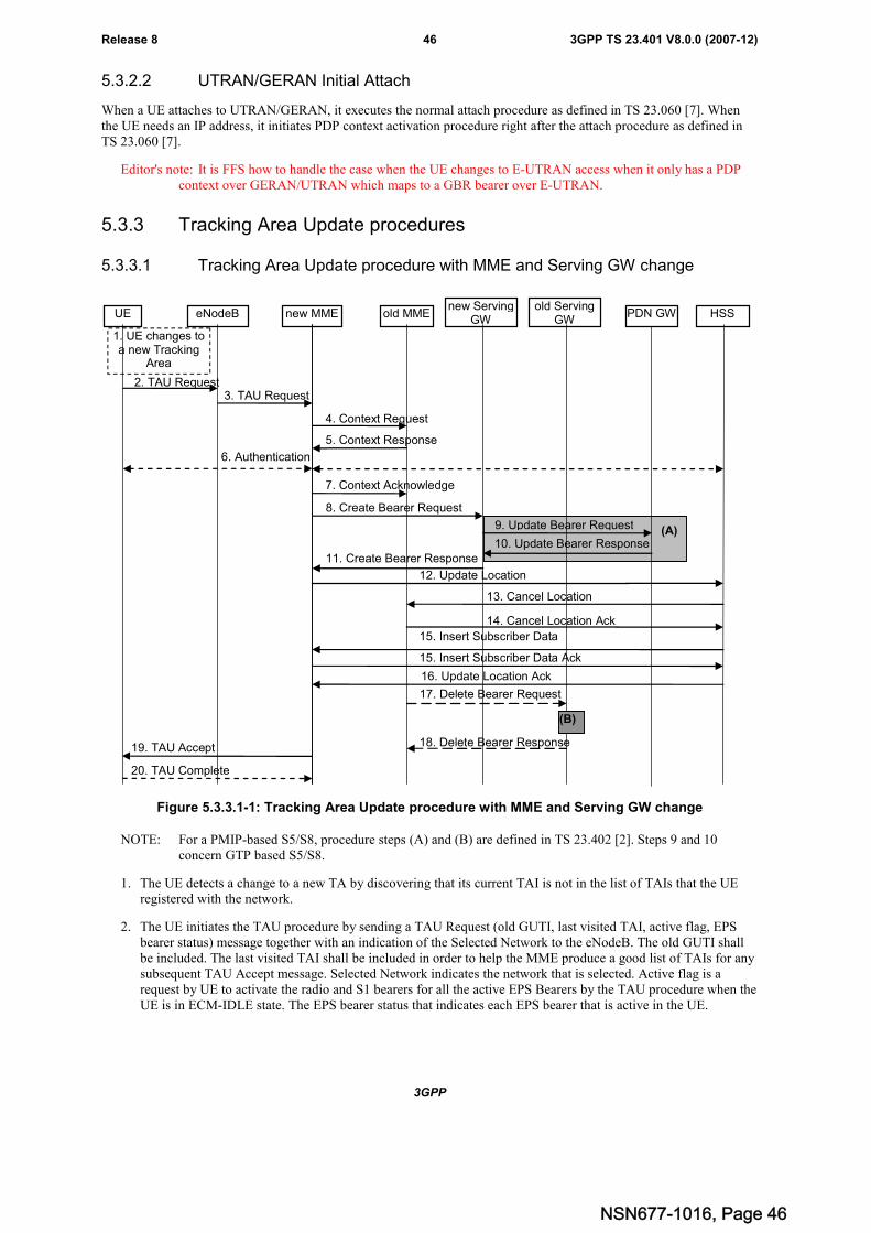
3GPP
3GPP TS 23.401 V8.0.0 (2007-12)46Release 8
5.3.2.2 UTRAN/GERAN Initial Attach
When a UE attaches to UTRAN/GERAN, it executes the normal attach procedure as defined in TS 23.060 [7]. Whenthe UE needs an IP address, it initiates PDP context activation procedure right after the attach procedure as defined inTS 23.060 [7].
Editor's note: It is FFS how to handle the case when the UE changes to E-UTRAN access when it only has a PDPcontext over GERAN/UTRAN which maps to a GBR bearer over E-UTRAN.
5.3.3 Tracking Area Update procedures
5.3.3.1 Tracking Area Update procedure with MME and Serving GW change
(A)
4. Context Request
2. TAU Request
new MME old MMEnew Serving
GWPDN GW HSS
1. UE changes toa new Tracking
Area
5. Context Response
6. Authentication
12. Update Location
13. Cancel Location
15. Insert Subscriber Data
14. Cancel Location Ack
17. Delete Bearer Request
18. Delete Bearer Response19. TAU Accept
20. TAU Complete
7. Context Acknowledge
old ServingGW
3. TAU Request
eNodeBUE
11. Create Bearer Response
8. Create Bearer Request
9. Update Bearer Request
10. Update Bearer Response
16. Update Location Ack
(B)
15. Insert Subscriber Data Ack
Figure 5.3.3.1-1: Tracking Area Update procedure with MME and Serving GW change
NOTE: For a PMIP-based S5/S8, procedure steps (A) and (B) are defined in TS 23.402 [2]. Steps 9 and 10concern GTP based S5/S8.
1. The UE detects a change to a new TA by discovering that its current TAI is not in the list of TAIs that the UEregistered with the network.
2. The UE initiates the TAU procedure by sending a TAU Request (old GUTI, last visited TAI, active flag, EPSbearer status) message together with an indication of the Selected Network to the eNodeB. The old GUTI shallbe included. The last visited TAI shall be included in order to help the MME produce a good list of TAIs for anysubsequent TAU Accept message. Selected Network indicates the network that is selected. Active flag is arequest by UE to activate the radio and S1 bearers for all the active EPS Bearers by the TAU procedure when theUE is in ECM-IDLE state. The EPS bearer status that indicates each EPS bearer that is active in the UE.
NSN677-1016, Page 46
3GPP
3GPP TS 23.401 V8.0.0 (2007-12)47Release 8
Editor's note: It has yet to be determined whether message 2 is only sent in ECM-CONNECTED state (e.g. it ispreceded by a Service Request (type=signalling) procedure), or, whether message 1 can be used toestablish an S1 connection (in which case, the message needs to carry the S-TMSI).
3. The eNodeB derives the MME from the GUTI and from the indicated Selected Network. If that MME is notassociated with that eNodeB,the eNodeB selects an MME as described in clause 4.3.8.3 on "MME SelectionFunction".
The eNodeB forwards the TAU Request message together with an indication of the E-UTRAN Area Identity, aglobally unique E-UTRAN ID, of the cell from where it received the message and with the Selected Network tothe new MME.
4. The new MME sends a Context Request (old GUTI) message to the old MME to retrieve user information. Thenew MME derives the old MME from the GUTI. If the new MME indicates that it has authenticated the UE or ifthe old MME correctly validates the UE, then the old MME starts a timer.
Editor's note: It is FFS if the legacy solution with S-TMSI Signature shall be used for integrity check of the messageor if the NAS security functionality can be used.
5. The old MME responds with a Context Response (MME context (e.g. IMSI, Authentication Quintets, bearercontexts, Serving GW signalling Address and TEID(s)) message. The PDN GW Address and TEID(s) is part ofthe Bearer Context. If the UE is not known in the old MME, the old MME responds with an appropriate errorcause.
6. The authentication functions are defined in clause "Security Function". Ciphering procedures are described inclause "Security Function". If GUTI allocation is going to be done and the network supports ciphering, the NASmessages shall be ciphered.
7. The new MME sends a Context Acknowledge message to the old MME. The old MME marks in its context thatthe information in the GWs and the HSS are invalid. This ensures that the old MME updates the GWs and theHSS if the UE initiates a TAU procedure back to the old MME before completing the ongoing TAU procedure.If the security functions do not authenticate the UE correctly, then the TAU shall be rejected, and the new MMEshall send a reject indication to the old MME. The old MME shall continue as if the Identification and ContextRequest was never received.
8. The MME constructs an MM context for the UE. The MME verifies the EPS bearer status received from the UEwith the bearer contexts received from the old MME and releases any network resources related to EPS bearersthat are not active in the UE. The new MME determines whether to relocate the Serving GW or not. The ServingGW is relocated when the old Serving GW cannot continue to serve the UE. The new MME may also decide torelocate the Serving GW in case a new Serving GW is expected to serve the UE longer and/or with a moreoptimal UE to PDN GW path, or in case a new Serving GW can be co-located with the PDN GW. Selection of anew Serving GW is performed according to clause 4.3.8.2 on "Serving GW selection function". If the new MMEselected a new Serving GW it sends a Create Bearer Request (IMSI, bearer contexts, MME Context ID) messageto the selected new Serving GW. The PDN GW address is indicated in the bearer Contexts.
9. The new Serving GW sends the message Update Bearer Request (Serving GW Address, Serving GW TunnelEndpoint Identifier) to the PDN GW concerned.
10. The PDN GW updates its bearer contexts and returns an Update Bearer Response (PDN GW address andTEID(s)) message.
11. The Serving GW updates its bearer context. This allows the Serving GW to route bearer PDUs to the PDN GWwhen received from eNodeB.
The Serving GW returns a Create Bearer Response (MME Context ID, Serving GW address and TEID for userplane, Serving GW Context ID) message to the new MME.
12. The new MME sends an Update Location (MME Identity, IMSI) message to the HSS.
13. The HSS sends the message Cancel Location (IMSI, Cancellation Type) to the old MME with Cancellation Typeset to Update Procedure.
14. If the timer started in step 4 is not running, the old MME removes the MM context. Otherwise, the contexts areremoved when the timer expires. It also ensures that the MM context is kept in the old MME for the case the UE
NSN677-1016, Page 47
3GPP
3GPP TS 23.401 V8.0.0 (2007-12)48Release 8
initiates another TAU procedure before completing the ongoing TAU procedure to the new SGSN. The oldMME acknowledges with the message Cancel Location Ack (IMSI).
15. The HSS sends Insert Subscriber Data (IMSI, Subscription Data) to the new MME. The new MME validates theUE's presence in the (new) TA. If due to regional subscription restrictions or access restrictions the UE is notallowed to be attached in the TA, the MME rejects the Tracking Area Update Request with an appropriate causeto the UE, and may return an Insert Subscriber Data Ack (IMSI, MME Area Restricted) message to the HSS. Ifall checks are successful, the MME constructs an MM context for the UE and returns an Insert Subscriber DataAck (IMSI) message to the HSS.
16. The HSS acknowledges the Update Location message by sending an Update Location Ack to the new MME. Ifthe Update Location is rejected by the HSS, the new MME rejects the Attach Request from the UE with anappropriate cause.
17. When the old MME removes the MM context, the old MME deletes the EPS bearer resources by sending DeleteBearer Request (TEID) messages to the Serving GW. Cause indicates to the old Serving GW that the old ServingGW shall not initiate a delete procedure towards the PDN GW. If the Serving GW has not changed, the ServingGW does not delete the bearers. If the MME has not changed, step 11 triggers the release of EPS bearerresources when a new Serving GW is allocated.
18. The Serving GW acknowledges with Delete Bearer Response (TEID) messages.
19. The new MME validates the UE's presence in the (new) TA, after it has received valid and updated subscriptiondata. If due to regional subscription restrictions or access restrictions the UE is not allowed to attach in the TA,the MME rejects the TAU Request with an appropriate cause. If subscription checking fails for other reasons, theMME rejects the TAU Request with an appropriate cause. If all checks are successful then the MME sends aTAU Accept (GUTI, TAI list, EPS bearer status) message to the UE. GUTI is included if the MME allocates anew GUTI. If the "active flag" is set in the TAU Request message the user plane setup procedure can beactivated in conjunction with the TAU Accept message. The procedure is described in detail in TS 36.300 [5].The message sequence should be the same as for the UE triggered Service Request procedure specified in clause5.3.4.1 from the step when MME establishes the bearer(s). The MME indicates the EPS bearer status IE to theUE. The UE removes any internal resources related to bearers that are not marked active in the received EPSbearer status.
20. If GUTI was included in the TAU Accept, the UE acknowledges the received message by returning a TAUComplete message to the MME.
When the "Active flag" is not set in the TAU Request message and the Tracking Area Update was not initiatedas the part of the handover, the new MME releases the signalling connection with UE, according to the clause5.3.5.
5.3.3.2 E-UTRAN Tracking Area Update
The Tracking Area Update procedure takes place when a UE that is registered with an MME and/or a 3G-SGSN selectsan E-UTRAN cell. The procedure is initiated by the UE, if the UE changes thereby to a Tracking Area that the UE hasnot yet registered with the network or if the P-TMSI update status is "not updated" due to bearer configurationmodifications performed between UE and SGSN when ISR is activated. This procedure is initiated by an idle state UE.The cell selection is described in TS 25.304 [12] and TS 25.331 [33].
This TA update case is illustrated in Figure 5.3.3.2-1.
NSN677-1016, Page 48
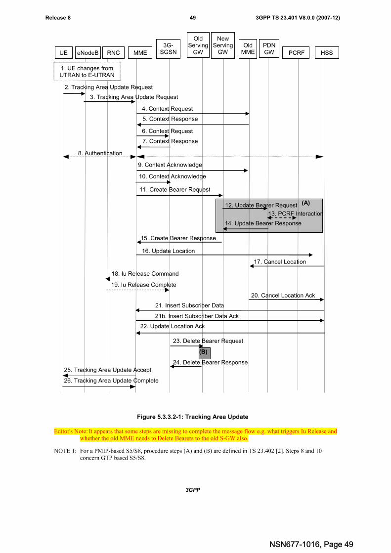
3GPP
3GPP TS 23.401 V8.0.0 (2007-12)49Release 8
2. Tracking Area Update Request
16. Update Location
5. Context Response
8. Authentication
25. Tracking Area Update Accept
17. Cancel Location
9. Context Acknowledge
4. Context Request
18. Iu Release Command
19. Iu Release Complete
26. Tracking Area Update Complete
UE eNodeB MME
3G-SGSN
OldServing
GWPDNGW HSS
3. Tracking Area Update Request
22. Update Location Ack
20. Cancel Location Ack
11. Create Bearer Request
15. Create Bearer Response
12. Update Bearer Request
14. Update Bearer Response
RNC
(A)
21. Insert Subscriber Data
21b. Insert Subscriber Data Ack
13. PCRF Interaction
PCRF
OldMME
7. Context Response
6. Context Request
10. Context Acknowledge
23. Delete Bearer Request
24. Delete Bearer Response
(B)
NewServing
GW
1. UE changes fromUTRAN to E-UTRAN
Figure 5.3.3.2-1: Tracking Area Update
Editor's Note: It appears that some steps are missing to complete the message flow e.g. what triggers Iu Release andwhether the old MME needs to Delete Bearers to the old S-GW also.
NOTE 1: For a PMIP-based S5/S8, procedure steps (A) and (B) are defined in TS 23.402 [2]. Steps 8 and 10concern GTP based S5/S8.
NSN677-1016, Page 49
3GPP
3GPP TS 23.401 V8.0.0 (2007-12)50Release 8
1. The UE selects an E-UTRAN cell of a Tracking Area which is not in the UE's list of TAI's that the UE registeredwith the network.
2. The UE initiates a TAU procedure by sending a Tracking Area Update Request (UE Network Capability, activeflag, old RAI, old P-TMSI, EPS bearer status, Update Type, GUTI (if available), P-TMSI signature) message tothe eNodeB. Selected Network indicates the network that is selected. Active flag is a request by the UE toactivate the radio and S1 bearers for all the active EPS Bearers by the TAU procedure. Old TAI and old S-TMSIare included if the UE holds a valid S-TMSI. Old RAI and old P-TMSI are included if the UE holds a valid P-TMSI. The EPS bearer status indicates each EPS bearer that is active within the UE. Update Type is set to "ISRsync" when the UE has performed 2G/3G PDP context setup/modification/release procedures and there was nosignalling with the MME yet. The UE's ISR capability is included in the UE Network Capability element.
3. The eNodeB shall add the E-UTRAN Area Identity before forwarding the message to the MME. This E-UTRANArea Identity is a globally unique E-UTRAN ID for the eNodeB the UE is connected to. If that GUMMEI is notassociated with the eNodeB, or the GUMMEI is not available, the eNodeB selects the MME as described inclause 4.3.8.3 on "MME Selection Function". The eNodeB forwards the TAU Request message together with theE-UTRAN Area Identity and with the Selected Network to the MME.
Editor's note: It has yet to be determined whether message 2 is only sent in ECM-CONNECTED state (e.g. it ispreceded by a Service Request (type=signalling) procedure), or, whether message 1 can be used toestablish an S1 connection (in which case, the message needs to carry the S-TMSI).
Editor's Note: It is FFS how the S-TMSI and P-TMSI handling is performed to let RAN select the same CN node forGERAN/UTRAN access as for E-UTRAN access, this to support co-location of the MME function andthe SGSN function in one node.
Editor's Note: It is FFS whether and how an S-TMSI is derived from the P-TMSI. It is also FFS whether thisfacilitates the collocated MME/SGSN or whether additional information is used for this.
4. If the UE provided an S-TMSI, the new MME sends a Context Request (old TAI, old S-TMSI, MME Address,P-TMSI signature) message to the old MME to retrieve the user information. The MME derives the old MMEfrom the old TAI and old S-TMSI. If the new MME indicates that it has authenticated the UE or if the old MMEauthenticates the UE, the old SGSN starts a timer.
Editor's note: It is FFS how the old MME validates the TAU Request.
5. The old MME responds with one Context Response (Context) message. PDP contexts, PDN GW Address, andServing GW Address are part of the Context. The PDP Contexts shall be sent in a prioritized order, i.e. the mostimportant PDP Context first. The prioritization method is implementation dependent, but should be based on thecurrent activity.
NOTE 2: Assigning the highest priority to the PDP context without TFT could be done to get service continuity forall ongoing services regardless of the number of supported EPS bearers in the UE and network.
The MME shall ignore the UE Network Capability contained in the Context of Context Response only when ithas previously received an UE Network Capability in the Tracking Area Update Request. If the UE is not knownin the old MME, the old MME responds with an appropriate error cause.
The new MME maps the PDP contexts to the EPS bearers 1-to-1 and maps the pre-Rel-8 QoS parameter valuesof a PDP context to the EPS QoS parameter values of an EPS bearer as defined in Annex E. The MMEestablishes the EPS bearer(s) in the indicated order. The MME deactivates the EPS bearers which cannot beestablished.
6. If the UE provided a P-TMSI and the Update Type is "ISR synch" or if the UE provided a P-TMSI and the MMEwants to activate ISR the new MME sends an SGSN Context Request (old RAI, old P-TMSI, MME Address)message to the old SGSN to retrieve the user information. The new MME derives the old SGSN from the oldRAI and old P-TMSI. P-TMSI Signature is used by the SGSN for integrity check. If the new MME indicates thatit has authenticated the UE or if the old SGSN authenticates the UE, the old SGSN starts a timer.
Editor's Note: It is FFS how the old MME validates the Context Request.
7. The old SGSN responds with an SGSN Context Response (SGSN context (e.g. IMSI, Authentication Quintets,bearer contexts, Serving GW signalling Address and TEID(s), ISR) message. PDN GW Address and ServingGW Address are part of the Context. If the UE is not known in the old SGSN, the old SGSN responds with anappropriate error cause. ISR indicates that the old SGSN is capable to establish ISR for the UE.
NSN677-1016, Page 50
3GPP
3GPP TS 23.401 V8.0.0 (2007-12)51Release 8
8. Authentication functions and ciphering procedures are defined in the clause "Security Function". Securityfunctions may be executed.
9. The MME sends a Context Acknowledge message to the oldMME. The old MME marks in its context that theinformation in the GWs and the HSS are invalid. This ensures that the MME updates the GWs and the HSS if theUE initiates a TAU procedure back to the MME before completing the ongoing TAU procedure.
If the security functions do not authenticate the UE correctly, then the TAU shall be rejected, and the MME shallsend a reject indication to the old MME. The old MME shall continue as if the Identification and ContextRequest was never received.
10. The MME sends an SGSN Context Acknowledge (ISR) message to the old SGSN. Unless ISR is indicated bythe MME the old SGSN marks in its context that the information in the GWs and the HSS are invalid. Thisensures that the SGSN updates the GWs and the HSS if the UE initiates a RAU procedure back to the SGSNbefore completing the ongoing TAU procedure. ISR indicates to the old SGSN that it shall maintain the UE'scontexts and the SGSN stops the timer started in step 6.
If the security functions do not authenticate the UE correctly, then the TAU shall be rejected, and the MME shallsend a reject indication to the old SGSN. The old SGSN shall continue as if the Identification and ContextRequest was never received.
11. If the UE indicated update type "ISR synch" the new MME adopts the bearer contexts received from the SGSNas the UE's EPS bearer contexts to be maintained by the new MME. The new MME verifies EPS bearer statusreceived from UE with the EPS bearer contexts it maintains and releases any network resources related to EPSbearers that are not active in the UE. The MME determines whether to relocate the Serving GW or not. TheServing GW is relocated when the old Serving GW cannot continue to serve the UE. The new MME may alsodecide to relocate the Serving GW in case a new Serving GW is expected to serve the UE longer and/or with amore optimal UE to PDN GW path, or in case a new Serving GW can be co-located with the PDN GW.Selection of a new Serving GW is performed according to clause 4.3.8.2 on "Serving GW selection function".
If the MME selected a new Serving GW, it sends a Create Bearer Request (IMSI, bearer contexts, MME ContextID, RAT Type, etc) message to the selected new Serving GW. The PDN GW address is indicated in the bearercontexts.
If the old Serving GW continues to serve the UE, the new MME sends an Update Bearer Request (new MMEaddress and TEID, QoS Negotiated, Serving network identity, ISR) message to the Serving GW. The PDN GWaddress is indicated in the bearer contexts. The information element ISR indicates whether ISR is established.
Editor's note: it is FFS how to handle the case when the UE has no PDP contexts.
12. If the MME selected a new Serving GW, the new Serving GW sends the message Update Bearer Request(Serving GW Address, Serving GW Tunnel Endpoint Identifier) to the PDN GW concerned.
If the old Serving GW continues to serve the UE, the old Serving GW informs the PDN GW(s) the change of forexample the RAT type that e.g. can be used for charging, by sending the message Update Bearer Request(Serving GW Address and TEID, RAT type, etc.) to the PDN GW(s) concerned.
If PCC infrastructure is used, the PDN GW informs the PCRF about the change of, for example, the RAT type.
13. If dynamic PCC is deployed, and RAT type information needs to be conveyed from the PDN GW to the PCRF,then Tthe PDN GW may shall send RAT type information to the PCRF.
NOTE 3: The PDN GW does not need to wait for the PCRF response, but continues in the next step. If the PCRFresponse leads to an EPS bearer modification the PDN GW should initiate a bearer update procedure.
14. The PDN GW updates its context field to allow DL PDUs to be routed to the correct Serving GW. PDN GWreturns an Update Bearer Response (PDN GW address and TEID, etc.) to the Serving GW.
15. If the MME selected a new Serving GW in step 11), the new Serving GW updates its bearer context. This allowsthe Serving GW to route Bearer PDUs to the PDN GW when received from eNodeB.
The new Serving GW returns a Create Bearer Response message to the new MME.
If the old Serving GW continues to serve the UE in step 11), the Serving GW updates its bearer context. Thisallows the Serving GW to route Bearer PDUs to the PDN GW when received from eNodeB. The Serving GW
NSN677-1016, Page 51
3GPP
3GPP TS 23.401 V8.0.0 (2007-12)52Release 8
returns an Update Bearer Response (Serving GW address and TEID, PDN GW Address and TEID, etc) messageto the MME.
Editor's note: It is FFS whether the same SGW address and TEIDs are used for S4 and S1 or whether separateparameters are needed.
16. The new MME informs the HSS of the change of MME by sending an Update Location (MME Id, IMSI)message to the HSS.
Editor's note: It is FFS whether this signalling is also needed if there is no MME change, e.g. when ISR is activatedor deactivated.
17. The HSS sends a Cancel Location (IMSI, Cancellation type) message to the old MME with a Cancellation Typeset to Update Procedure.
18. If the UE is Iu Connected, the old SGSN sends an Iu Release Command message to the RNC.
19. The RNC responds with an Iu Release Complete message.
20. If the timer started in step 4 is not running, the old MME removes the MM context. Otherwise, the contexts areremoved when the timer expires. It also ensures that the MM context is kept in the old MME for the case the UEinitiates another TAU procedure before completing the ongoing TAU procedure to the new MME. The old MMEacknowledges with a Cancel Location Ack (IMSI) message.
If the timer started in step 6 is not running and ISR was not indicated by the MME, the old SGSN removes theMM context. Otherwise, the contexts are removed when the timer expires. It also ensures that the MM context iskept in the old SGSN for the case the UE initiates another RAU procedure before completing the ongoing TAUprocedure to the new MME.
21 The HSS sends Insert Subscriber Data (IMSI, Subscription Data) to the new MME. The new MME validates theUE's presence in the (new) TA. If due to regional subscription restrictions or access restrictions the UE is notallowed to be attached in the TA, the MME rejects the Tracking Area Update Request with an appropriate causeto the UE, and may return an Insert Subscriber Data Ack (IMSI, MME Area Restricted) message to the HSS. Ifall checks are successful, the MME constructs an MM context for the UE and returns an Insert Subscriber DataAck (IMSI) message to the HSS.
22. The HSS acknowledges the Update Location by returning an Update Location Ack (IMSI) message to the newMME after the cancelling of the old MME context is finished. If the Update Location is rejected by the HSS, theMME rejects the TAU Request from the UE with an appropriate cause sent in the TAU Reject message to theUE.
23. When the SGSN removes the MM context in step 20), the SGSN deletes the EPS bearer resources anytime bysending Delete Bearer Request (TEID) messages to the old Serving GW. Cause indicates to the old Serving GWthat the old Serving GW shall not initiate a delete procedure towards the PDN GW. If the Serving GW has notchanged, the Serving GW does not delete the bearers.
24. The old Serving GW acknowledges with Delete Bearer Response (TEID) messages.
25. The MME validate the UE's presence in the new TA, after it has received valid and updated subscription data. Ifdue to regional subscription restrictions or access restrictions the UE is not allowed to attach in the TA, theMME rejects the Tracking Area Update Request with an appropriate cause sent in the TAU Reject message tothe UE.
If validation is successful the MME responds to the UE with a Tracking Area Update Accept (GUTI, TAI-list,EPS bearer status, ISR) message. Restriction list shall be sent to eNodeB as eNodeB handles the roamingrestrictions and access restrictions in the Intra E-UTRAN case. If the "active flag" is set in the TAU Requestmessage the user plane setup procedure is activated in conjunction with the TAU Accept message. Theprocedure is described in detail in TS 36.300 [5]. The message sequence should be the same as for the UEtriggered Service Request procedure specified in clause 5.3.4.1 from the step when MME establish thebearers(s). The EPS bearer status indicates the active bearers in the network. The UE removes any internalresources related to bearers not marked active in the received EPS bearer status. ISR indicates to the UE that itsP-TMSI and RAI remain registered with the network and remain valid in the UE. If ISR is not indicated the UEsets in its internal data the update status of the P-TMSI to "not updated".
26. The UE acknowledges the message by returning a Tracking Area Update Complete message to the MME.
NSN677-1016, Page 52
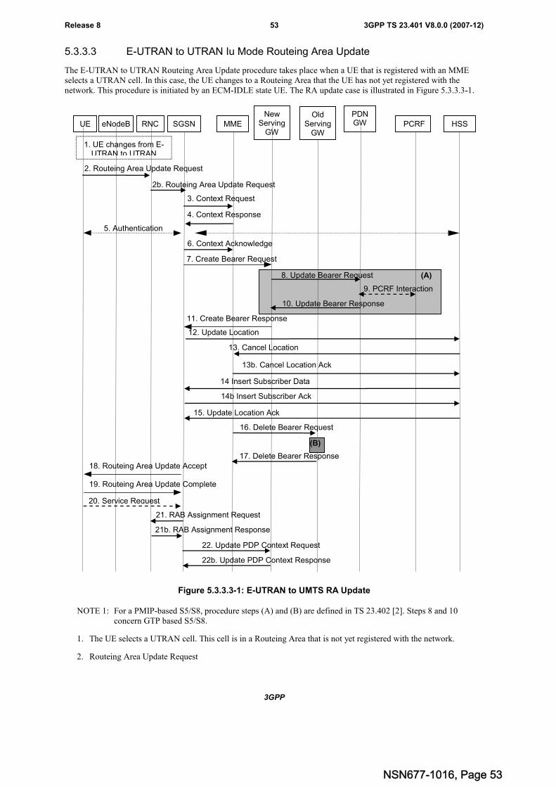
3GPP
3GPP TS 23.401 V8.0.0 (2007-12)53Release 8
5.3.3.3 E-UTRAN to UTRAN Iu Mode Routeing Area Update
The E-UTRAN to UTRAN Routeing Area Update procedure takes place when a UE that is registered with an MMEselects a UTRAN cell. In this case, the UE changes to a Routeing Area that the UE has not yet registered with thenetwork. This procedure is initiated by an ECM-IDLE state UE. The RA update case is illustrated in Figure 5.3.3.3-1.
(A)
2. Routeing Area Update Request
12. Update Location
15. Update Location Ack
4. Context Response
5. Authentication
18. Routeing Area Update Accept
13. Cancel Location
13b. Cancel Location Ack
6. Context Acknowledge
3. Context Request
19. Routeing Area Update Complete
UE eNodeB SGSN MME
NewServing
GW
PDNGW HSS
1. UE changes from E-UTRAN to UTRAN
2b. Routeing Area Update Request
7. Create Bearer Request
11. Create Bearer Response
8. Update Bearer Request
10. Update Bearer Response
21. RAB Assignment Request
21b. RAB Assignment Response
20. Service Request
RNC
22. Update PDP Context Request
22b. Update PDP Context Response
14 Insert Subscriber Data
14b Insert Subscriber Ack
9. PCRF Interaction
PCRFOld
ServingGW
16. Delete Bearer Request
17. Delete Bearer Response
(B)
Figure 5.3.3.3-1: E-UTRAN to UMTS RA Update
NOTE 1: For a PMIP-based S5/S8, procedure steps (A) and (B) are defined in TS 23.402 [2]. Steps 8 and 10concern GTP based S5/S8.
1. The UE selects a UTRAN cell. This cell is in a Routeing Area that is not yet registered with the network.
2. Routeing Area Update Request
NSN677-1016, Page 53
3GPP
3GPP TS 23.401 V8.0.0 (2007-12)54Release 8
a. The UE sends a Routeing Area Update Request (old P-TMSI, old RAI, UE Network Capability) message tothe SGSN. In the information element old RAI the UE indicates the GUMMEI the UE registered with thenetwork. In the information element old P-TMSI the UE indicates the M-TMSI that is allocated to the UE.(This is FFS pending conclusion on the mapping of MMEC to the P-TMSI field and mapping of part of theM-TMSI to the P-TMSI signature field). If the UE has a follow-on request, i.e. if there is pending uplinktraffic (signalling or data),the SGSN may use, as an implementation option, the follow-on request indicationto release or keep the Iu connection after the completion of the RA update procedure.
Editor's note: It is FFS whether, for O+M purposes, the Release 8 RAU Request should be extended to carry the lastvisited TAI.
b. The RNC shall add the Routeing Area Identity before forwarding the message to the SGSN. This RA identitycorresponds to the RAI in the MM system information sent by the RNC to the UE.
Editor's Note: It is FFS how the S-TMSI and P-TMSI handling is performed to let RAN select the same CN node forGERAN/UTRAN access as for E-UTRAN access, this to support co-location of the MME function andthe SGSN function in one node.
3. The new SGSN uses the GUMMEI to derive the MME address, and sends a Context Request (GUTI, NewSGSN Address) message to the MME to get the context for the UE. If the new SGSN indicates that it hasauthenticated the UE or if the old MME authenticates the UE, the old MME starts a timer.
4. The old MME responds with one Context Response (MME Context) message. PDP contexts, PDN GW address,and Serving GW address are part of the MME Context. The old MME maps the EPS bearers to PDP contexts 1-to-1 and maps the EPS QoS parameter values of an EPS bearer to the pre-Rel-8 QoS parameter values of a PDPcontext as defined in Annex E. The PDP Contexts shall be sent in a prioritized order, i.e. the most important PDPContext first. The prioritization method is implementation dependent, but should be based on the current activity.
NOTE 2: Assigning the highest priority to the PDP context without TFT could be done to get service continuity forall ongoing services regardless of the number of supported EPS bearers in the UE and network.
The new SGSN shall ignore the UE Network Capability contained in the context of Context Response only whenit has previously received an UE Network Capability in the Routeing Area Update Request. If UE is not knownin the old MME, the old MME responds with a appropriate error cause.
The new SGSN establishes the PDP context(s) in the indicated order. The SGSN deactivates the PDP contextswhich cannot be established.
5. Authentication functions and ciphering procedures are defined in the clause "Security Function". Securityfunctions may be executed.
6. The new SGSN sends an Context Acknowledge message to the old MME. The old MME marks in its contextthat the information in the GWs and the HSS are invalid. This ensures that the old MME updates the GWs andthe HSS if the UE initiates a TAU procedure back to the old MME before completing the ongoing TAUprocedure.
7. The SGSN determines whether to relocate the Serving GW or not. The Serving GW is relocated when the oldServing GW cannot continue to serve the UE. The SGSN may also decide to relocate the Serving GW in case anew Serving GW is expected to serve the UE longer and/or with a more optimal UE to PDN GW path, or in casea new Serving GW can be co-located with the PDN GW. Selection of a new Serving GW is performed accordingto clause 4.3.8.2 on "Serving GW selection function".
If the SGSN selected a new Serving GW, it sends a Create Bearer Request (IMSI, bearer contexts, SGSNContext ID, RAT Type, etc) message to the selected new Serving GW. The PDN GW address is indicated in thebearer contexts..
If the old Serving GW continues to serve the UE, the SGSN sends an Update Bearer Request (new SGSNAddress and TEID, QoS Negotiated, serving network identity, RAT type) message to the Serving GW.
8. If the SGSN selected a new Serving GW, the new Serving GW sends the message Update Bearer Request(Serving GW Address, Serving GW Tunnel Endpoint Identifier) to the PDN GW concerned.
If the old Serving GW continues to serve the old Serving GW informs the PDN GW(s) the change of forexample the RAT type that e.g. can be used for charging, by sending the message Update Bearer Request(Serving GW Address and TEID, RAT type, etc.) to the PDN GW(s) concerned.
NSN677-1016, Page 54
3GPP
3GPP TS 23.401 V8.0.0 (2007-12)55Release 8
If PCC infrastructure is used, the PDN GW informs the PCRF about the change of, for example, the RAT type.
9. If dynamic PCC is deployed, and RAT type information needs to be conveyed from the PDN GW to the PCRF,then the PDN GW shall send RAT type information to the PCRF.
NOTE 3: The PDN GW does not need to wait for the PCRF response, but continues in the next step. If the PCRFresponse leads to an EPS bearer modification the PDN GW should initiate a bearer update procedure.
10. The PDN GW updates its context field and returns an Update Bearer Response (PDN GW address and TEID,etc.) message to the Serving GW.
11. If the SGSN selected a new Serving GW in step 7), the new Serving GW updates its bearer context. This allowsthe Serving GW to route Bearer PDUs to the PDN GW when received from RNC. The new Serving GW returnsan Create Bearer Response (Serving GW address and TEID, PDN GW Address and TEID, etc) message to theSGSN.
If the old Serving GW continues to serve the UE in step 7), the Serving GW updates its context fields and returnsan Update Bearer Response (Serving GW address and TEID, PDN GW address and TEID, etc) message.
12. The new SGSN informs the HSS of the change of MME to SGSN by sending an Update Location (SGSNNumber, SGSN Address, IMSI) message to the HSS.
13. The HSS sends a Cancel Location (IMSI, Cancellation Type) message to the old MME with the CancellationType set to Update Procedure.
If the timer started in step 3 is not running, the old MME removes the MM context. Otherwise, the contexts areremoved when the timer expires. It also ensures that the MM context is kept in the old MME for the case the UEinitiates another TAU procedure before completing the ongoing TAU procedure to the new SGSN. The oldMME acknowledges with a Cancel Location Ack (IMSI) message.
14 The HSS sends Insert Subscriber Data (IMSI, Subscription Data) to the new SGSN. The new SGSN validates theUE's presence in the (new) RA. If due to regional subscription restrictions or access restrictions the UE is notallowed to be attached in the RA, the SGSN rejects the Routeing Area Update Request with an appropriate causeto the UE, and may return an Insert Subscriber Data Ack (IMSI, SGSN Area Restricted) message to the HSS. Ifall checks are successful, the SGSN constructs an MM context for the UE and returns an Insert Subscriber DataAck (IMSI) message to the HSS.
15. The HSS acknowledges the Update Location message by sending an Update Location Ack to the new SGSN. Ifthe Update Location is rejected by the HSS, the new SGSN rejects the Attach Request from the UE with anappropriate cause.
16. When the old MME removes the MM context in step 13), the old MME deletes the EPS bearer resourcesanytime by sending Delete Bearer Request (TEID) messages to the old Serving GW. Cause indicates to the oldServing GW that the old Serving GW shall not initiate a delete procedure towards the PDN GW. If the ServingGW has not changed, the Serving GW does not delete the bearers.
17. The old Serving GW acknowledges with Delete Bearer Response (TEID) messages.
18. The new SGSN validate the UE's presence in the new RA, after it has received valid and updated subscriptiondata. If due to roaming restrictions or access restrictions the UE is not allowed to be attached in the RA, or ifsubscription checking fails, the new SGSN rejects the routeing area update with an appropriate cause sent in theRAU reject message to the UE.
If validation is successful the new SGSN responds to the UE with a Routeing Area Update Accept (P-TMSI, P-TMSI signature) message to the UE. P-TMSI is included if the SGSN allocates a new P-TMSI.
19. If P-TMSI was included in the Routeing Area Update Accept message, the UE acknowledges the new P-TMSIby returning a Routeing Area Update Complete message to the SGSN.
20. If the UE has uplink data or signalling pending it shall send a Service Request (P-TMSI, CKSN, Service Type)message to the SGSN. If a P-TMSI was allocated in step 18, that P-TMSI is the one included in this message.Service Type specifies the requested service. Service Type shall indicate one of the following: Data orSignalling.
NSN677-1016, Page 55
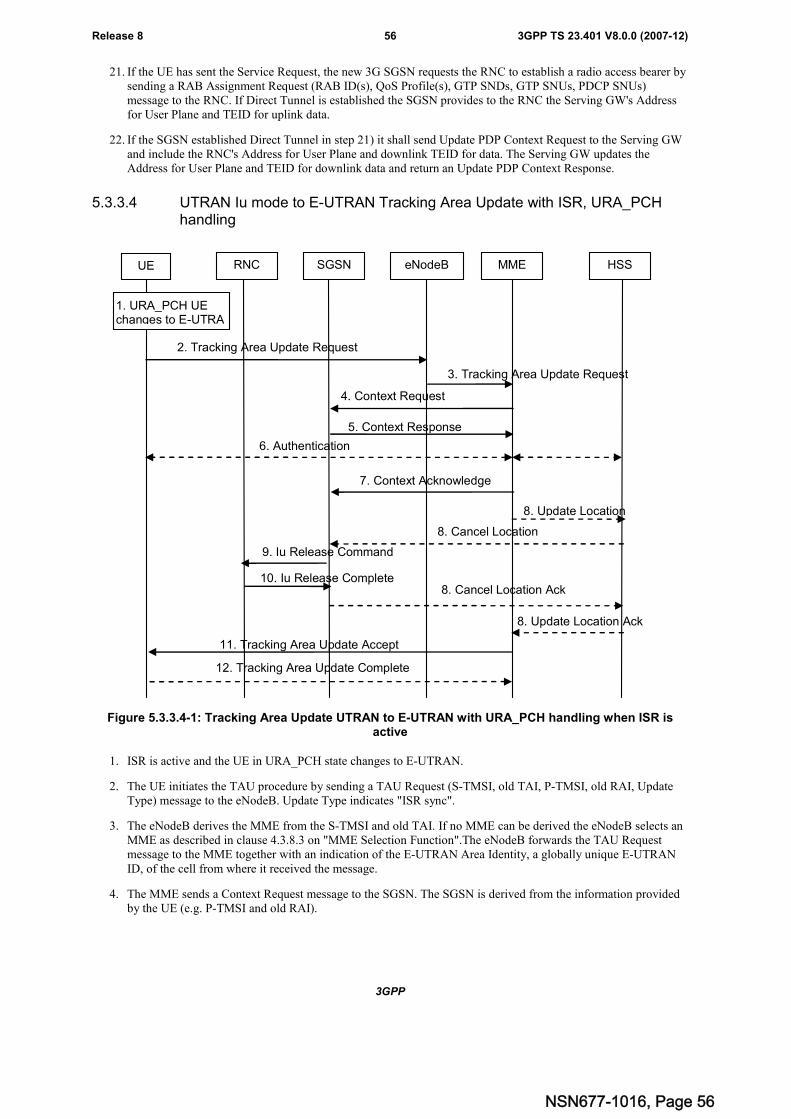
3GPP
3GPP TS 23.401 V8.0.0 (2007-12)56Release 8
21. If the UE has sent the Service Request, the new 3G SGSN requests the RNC to establish a radio access bearer bysending a RAB Assignment Request (RAB ID(s), QoS Profile(s), GTP SNDs, GTP SNUs, PDCP SNUs)message to the RNC. If Direct Tunnel is established the SGSN provides to the RNC the Serving GW's Addressfor User Plane and TEID for uplink data.
22. If the SGSN established Direct Tunnel in step 21) it shall send Update PDP Context Request to the Serving GWand include the RNC's Address for User Plane and downlink TEID for data. The Serving GW updates theAddress for User Plane and TEID for downlink data and return an Update PDP Context Response.
5.3.3.4 UTRAN Iu mode to E-UTRAN Tracking Area Update with ISR, URA_PCHhandling
UE SGSN MME HSS
2. Tracking Area Update Request
6. Authentication
5. Context Response
4. Context Request
9. Iu Release Command
10. Iu Release Complete
11. Tracking Area Update Accept
12. Tracking Area Update Complete
RNC eNodeB
3. Tracking Area Update Request
1. URA_PCH UEchanges to E-UTRA
7. Context Acknowledge
8. Update Location
8. Cancel Location
8. Update Location Ack
8. Cancel Location Ack
Figure 5.3.3.4-1: Tracking Area Update UTRAN to E-UTRAN with URA_PCH handling when ISR isactive
1. ISR is active and the UE in URA_PCH state changes to E-UTRAN.
2. The UE initiates the TAU procedure by sending a TAU Request (S-TMSI, old TAI, P-TMSI, old RAI, UpdateType) message to the eNodeB. Update Type indicates "ISR sync".
3. The eNodeB derives the MME from the S-TMSI and old TAI. If no MME can be derived the eNodeB selects anMME as described in clause 4.3.8.3 on "MME Selection Function".The eNodeB forwards the TAU Requestmessage to the MME together with an indication of the E-UTRAN Area Identity, a globally unique E-UTRANID, of the cell from where it received the message.
4. The MME sends a Context Request message to the SGSN. The SGSN is derived from the information providedby the UE (e.g. P-TMSI and old RAI).
NSN677-1016, Page 56
3GPP
3GPP TS 23.401 V8.0.0 (2007-12)57Release 8
5. The SGSN returns a Context Response (ISR) message to the MME. If the UE is not known in the SGSN, theSGSN responds with an appropriate error cause. ISR is indicated if the SGSN is able to provide ISR for the UE.
6. Authentication functions and ciphering procedures are defined in the clause "Security Function". Securityfunctions may be executed.
7. The MME sends a Context Acknowledge (ISR) message to the SGSN. ISR is indicated if the MME performsISR for the UE.
8. If the MME detects that the SGSN does not support ISR it sends Update Location to the HSS with update typeISR. The HSS sends a Cancel Location to the SGSN.
Editor's note: These steps are only needed if the Context Request/Response cannot delete the bearer resources in thepre-Rel-8 SGSN FFS
9. The SGSN sends an Iu Release Command message to the RNC if there is an Iu connection for this UE.
Editor's note: It is FFS how the old SGSN validates the TAU Request
10. The RNC deletes the UE RAN context and returns an Iu Release Complete message to the SGSN.
11. The new MME validates the UE's presence in the (new) TA. If due to regional subscription restrictions or accessrestrictions the UE is not allowed to attach in the TA, the MME rejects the TAU Request with an appropriatecause. If subscription checking fails for other reasons, the MME rejects the TAU Request with an appropriatecause. If all checks are successful then the MME sends a TAU Accept (S-TMSI, TAI list, ISR) message to theUE.
12. If S-TMSI or TAI list are included in the TAU Accept, the UE acknowledges the messageby returning a TAUComplete message to the MME.
5.3.3.5 GERAN A/Gb mode to E-UTRAN Tracking Area Update
The GERAN to E-UTRAN Tracking Area Update procedure takes place when a UE registered with an SGSN selects anE-UTRAN cell. In this case, the UE changes to a Tracking Area that the UE has not yet registered with the network.This procedure is initiated by an idle state UE and may also be initiated if the UE is in Active state. This TA update caseis illustrated in Figure 5.3.3.5-1.
NSN677-1016, Page 57
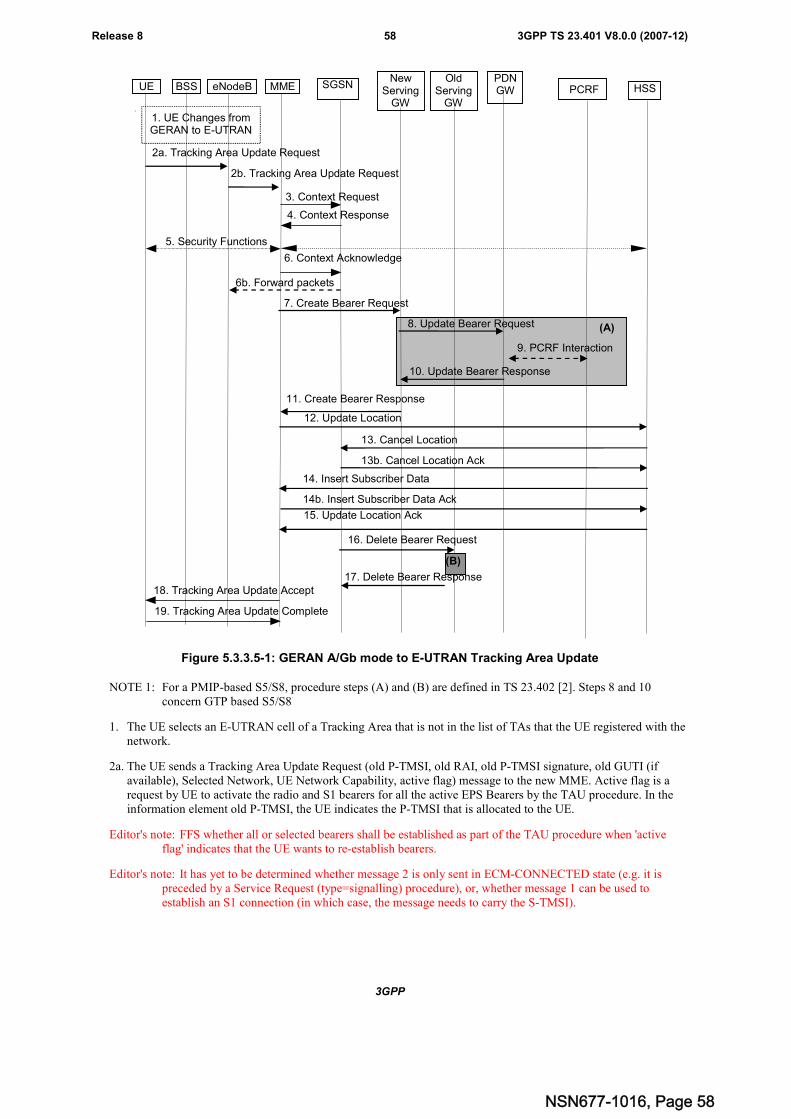
3GPP
3GPP TS 23.401 V8.0.0 (2007-12)58Release 8
2a. Tracking Area Update Request
12. Update Location
15. Update Location Ack
4. Context Response
5. Security Functions
18. Tracking Area Update Accept
13. Cancel Location
13b. Cancel Location Ack
6. Context Acknowledge
3. Context Request
19. Tracking Area Update Complete
UE BSS eNodeB SGSNMMENew
ServingGW
PDNGW HSS
1. UE Changes fromGERAN to E-UTRAN
2b. Tracking Area Update Request
7. Create Bearer Request
11. Create Bearer Response
8. Update Bearer Request
10. Update Bearer Response
6b. Forward packets
(A)
14b. Insert Subscriber Data Ack
14. Insert Subscriber Data
PCRF
9. PCRF Interaction
OldServing
GW
16. Delete Bearer Request
17. Delete Bearer Response
(B)
Figure 5.3.3.5-1: GERAN A/Gb mode to E-UTRAN Tracking Area Update
NOTE 1: For a PMIP-based S5/S8, procedure steps (A) and (B) are defined in TS 23.402 [2]. Steps 8 and 10concern GTP based S5/S8
1. The UE selects an E-UTRAN cell of a Tracking Area that is not in the list of TAs that the UE registered with thenetwork.
2a. The UE sends a Tracking Area Update Request (old P-TMSI, old RAI, old P-TMSI signature, old GUTI (ifavailable), Selected Network, UE Network Capability, active flag) message to the new MME. Active flag is arequest by UE to activate the radio and S1 bearers for all the active EPS Bearers by the TAU procedure. In theinformation element old P-TMSI, the UE indicates the P-TMSI that is allocated to the UE.
Editor's note: FFS whether all or selected bearers shall be established as part of the TAU procedure when 'activeflag' indicates that the UE wants to re-establish bearers.
Editor's note: It has yet to be determined whether message 2 is only sent in ECM-CONNECTED state (e.g. it ispreceded by a Service Request (type=signalling) procedure), or, whether message 1 can be used toestablish an S1 connection (in which case, the message needs to carry the S-TMSI).
NSN677-1016, Page 58
3GPP
3GPP TS 23.401 V8.0.0 (2007-12)59Release 8
2b. The eNodeB shall add the E-UTRAN Area Identity before forwarding the message to the MME. This E-UTRANArea identity globally unique E-UTRAN ID for the eNodeB the UE is connected to.The eNodeB derives theMME from the old GUMMEI (contained within the old GUTI) and the indicated Selected Network. If thatGUMMEI is not associated with the eNodeB, or the GUMMEI is not available, the eNodeB selects the MME asdescribed in clause 4.3.8.3 on "MME Selection Function".
Editor's Note: It is FFS how the S-TMSI and P-TMSI handling is performed to let RAN select the same CN node forGERAN/UTRAN access as for E-UTRAN access, this to support co-location of the MME function andthe SGSN function in one node.
3. The new MME uses the old RAI and P-TMSI received from the UE to derive the old SGSN address, and sends aContext Request (old RAI, old P-TMSI, New MME Address) message to the old SGSN to get the contexts forthe UE. The old SGSN validates the old P TMSI Signature and responds with an appropriate error cause if itdoes not match the value stored in the old SGSN. If the received old P-TMSI Signature does not match the storedvalue, the old SGSN should initiate the security functions in the new MME. If the security functions authenticatethe UE correctly, the new MME shall send a Context Request (old RAI, IMSI, UE Validated, New MMEAddress) message to the old SGSN. UE Validated indicates that the new MME has authenticated the UE. If theold P-TMSI Signature was valid or if the new MME indicates that it has authenticated the UE correctly. If thenew MME indicates that it has authenticated the UE or if the old SGSN authenticates the UE, the old SGSNstarts a timer.
Editor's note: it is FFS how the old SGSN validates the TAU Request.
4. The old SGSN responds with one Context Response (SGSN Context) message. The PDP contexts, PDN GWAddress and Serving GW Address are part of the SGSN Context. The PDP Contexts shall be sent in a prioritizedorder, i.e. the most important PDP Context first. The prioritization method is implementation dependent, butshould be based on the current activity.
NOTE 2: Assigning the highest priority to the PDP context without TFT could be done to get service continuity forall ongoing services regardless of the number of supported EPS bearers in the UE and network.
The new MME shall ignore the UE Network Capability contained in SGSN Context of Context Response onlywhen it has previously received an UE Network Capability in the Tracking Area Request. The SGSN Contextincludes also the Subscriber Data. If the UE is not known in the old SGSN, the old SGSN responds with anappropriate error cause.
The new MME maps the PDP contexts to the EPS bearers 1-to-1 and maps the pre-Rel-8 QoS parameter valuesof a PDP context to the EPS QoS parameter values of an EPS bearer as defined in Annex E. The MMEestablishes the EPS bearer(s) in the indicated order. The MME deactivates the EPS bearers which cannot beestablished.
5. Security functions may be executed. Procedures are defined in the clause "Security Function".
6. The new MME sends a Context Acknowledge message to the old SGSN. The old SGSN marks in its context thatthe information in the GWs and the HSS are invalid. This ensures that the old SGSN updates the GWs and theHSS if the UE initiates a TAU procedure back to the old SGSN before completing the ongoing TAU procedure.
If the security functions do not authenticate the UE correctly, then the TAU shall be rejected, and the MME shallsend a reject indication to the old SGSN. The old SGSN shall continue as if the Identification and ContextRequest was never received
Forwarding occurs if applicable.
Editor's note: It is FFS if data forwarding needs to be avoided for this procedure.
7. The MME determines whether to relocate the Serving GW or not. The Serving GW is relocated when the oldServing GW cannot continue to serve the UE. The new MME may also decide to relocate the Serving GW incase a new Serving GW is expected to serve the UE longer and/or with a more optimal UE to PDN GW path, orin case a new Serving GW can be co-located with the PDN GW. Selection of a new Serving GW is performedaccording to clause 4.3.8.2 on "Serving GW selection function".
If the MME selected a new Serving GW, it sends a Create Bearer Request (IMSI, bearer contexts, MME ContextID, RAT Type, etc) message to the selected new Serving GW. The PDN GW address is indicated in the bearercontexts.
NSN677-1016, Page 59
3GPP
3GPP TS 23.401 V8.0.0 (2007-12)60Release 8
If the old Serving GW continues to serve the UE, the MME sends an Update Bearer Request (new MMEAddress and TEID, QoS Negotiated, serving network identity) message to the Serving GW. The MME shall sendthe serving network identity to the Serving GW.
Editor's note: It is FFS how to handle the case when the UE has no PDP contexts.
8. If the MME selected a new Serving GW, the new Serving GW sends the message Update Bearer Request(Serving GW Address, Serving GW Tunnel Endpoint Identifier) to the PDN GW concerned.
If the old Serving GW continues to serve the UE, the old Serving GW informs the PDN GW(s) about the changeof the RAT type. The Serving GW sends an Update Bearer Request (Serving GW Address and TEID, RAT type,etc.) message to the PDN GW(s) concerned.
If PCC infrastructure is used, the PDN GW informs the PCRF about the change of, for example, the RAT type.
9. If dynamic PCC is deployed, and RAT type information needs to be conveyed from the PDN GW to the PCRF,then the PDN GW shall send RAT type information to the PCRF.
NOTE 3: The PDN GW does not need to wait for the PCRF response, but continues in the next step. If the PCRFresponse leads to an EPS bearer modification the PDN GW should initiate a bearer update procedure.
10. The PDN GW updates its context field and returns an Update Bearer Response (PDN GW address and TEID,etc.) message to the Serving GW.
11. If the MME selected a new Serving GW in step 7), the new Serving GW updates its context and returns anCreate Bearer Response (Serving GW address and TEID, PDN GW address and TEID, etc.) message to the newMME.
If the old Serving GW continues to serve the UE in step 7), the Serving GW updates its bearer context. Thisallows the Serving GW to route Bearer PDUs to the PDN GW when received from eNodeB. The Serving GWreturns an Update Bearer Response (Serving GW address and TEID, PDN GW Address and TEID, etc) messageto the MME.
12. The new MME informs the HSS of the change of SGSN by sending an Update Location (MME Address, IMSI)message to the HSS.
13. The HSS sends a Cancel Location (IMSI, Cancellation Type) message to the old SGSN with a Cancellation Typeset to Update Procedure. The old SGSN removes the contexts.
If the timer started in step 3 is not running, the old SGSN removes the MM context. Otherwise, the contexts areremoved when the timer expires. It also ensures that the MM context is kept in the old SGSN for the case the UEinitiates another TAU procedure before completing the ongoing TAU procedure to the new MME. The oldSGSN acknowledges with a Cancel Location Ack (IMSI) message.
14 The HSS sends Insert Subscriber Data (IMSI, Subscription Data) to the new MME. The new MME validates theUE's presence in the (new) TA. If due to regional subscription restrictions or access restrictions the UE is notallowed to be attached in the TA, the MME rejects the Tracking Area Update Request with an appropriate causeto the UE, and may return an Insert Subscriber Data Ack (IMSI, MME Area Restricted) message to the HSS. Ifall checks are successful, the MME constructs an MM context for the UE and returns an Insert Subscriber DataAck (IMSI) message to the HSS.
15. The HSS acknowledges the Update Location by sending an Update Location Ack message to the new MME. Ifthe Update Location is rejected by the HSS, the MME rejects the TAU Request from the UE with an appropriatecause sent in the TAU Reject message to the UE.
16. When the SGSN removes the MM context in step 13), the MME deletes the EPS bearer resources anytime bysending Delete Bearer Request (TEID) messages to the old Serving GW. Cause indicates to the old Serving GWthat the old Serving GW shall not initiate a delete procedure towards the PDN GW. If the Serving GW has notchanged, the Serving GW does not delete the bearers.
17. The old Serving GW acknowledges with Delete Bearer Response (TEID) messages.
18. The new MME validate the UE's presence in the new TA, after it has received valid and updated subscriptiondata. If due to roaming restrictions or access restrictions the UE is not allowed to be attached in the TA, or if
NSN677-1016, Page 60
3GPP
3GPP TS 23.401 V8.0.0 (2007-12)61Release 8
subscription checking fails, the new MME rejects the tracking area update with an appropriate cause sent in theTAU Reject message to the UE.
If all checks are successful, the new MME responds to the UE with a Tracking Area Update Accept (GUTI, TAI-list) message. If the "active flag" is set in the TAU Request message the user plane setup procedure can beactivated in conjunction with the TAU Accept message. The procedure is described in detail in TS 36.300 [5].The messages sequence should be the same as for the UE triggered Service Request procedure specified inclause 5.3.4.1 from the step when MME establishes the bearer(s).
19. If the GUTI was included in the TAU Accept message The UE acknowledges the message by returning aTracking Area Update Complete message to the MME.
5.3.3.6 E-UTRAN to GERAN Routeing Area Update
The E-UTRAN to GERAN Routeing Area Update procedure takes place when a UE that is registered with an MMEselects a GERAN cell. In this case, the UE changes to a Routeing Area that the UE has not yet registered with thenetwork.. This procedure is initiated by an ECM-IDLE state UE and may also be initiated if the UE is in ECM-CONNECTED state. This RA update case is illustrated in Figure 5.3.3.6-1.
NSN677-1016, Page 61
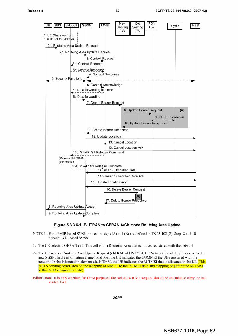
3GPP
3GPP TS 23.401 V8.0.0 (2007-12)62Release 8
(A)
2a. Routeing Area Update Request
7. Create Bearer Request
11. Create Bearer Response
12. Update Location
15. Update Location Ack
4. Context Response
5. Security Functions
18. Routeing Area Update Accept
13. Cancel Location
13. Cancel Location Ack
6. Context Acknowledge
3. Context Request
19. Routeing Area Update Complete
UE BSS eNodeB SGSN MMENew
ServingGW
PDNGW
HSS
1. UE Changes fromE-UTRAN to GERAN
8. Update Bearer Request
10. Update Bearer Response
2b. Routeing Area Update Request
3b. Context Request
3c. Context Response
6b Data forwarding command
6c Data forwarding
13c. S1-AP: S1 Release Command
Release E-UTRANconnection
13d. S1-AP: S1 Release Complete14. Insert Subscriber Data
14b. Insert Subscriber Data Ack
PCRF
9. PCRF Interaction
16. Delete Bearer Request
17. Delete Bearer Response
(B)
OldServing
GW
Figure 5.3.3.6-1: E-UTRAN to GERAN A/Gb mode Routeing Area Update
NOTE 1: For a PMIP-based S5/S8, procedure steps (A) and (B) are defined in TS 23.402 [2]. Steps 8 and 10concern GTP based S5/S8
1. The UE selects a GERAN cell. This cell is in a Routeing Area that is not yet registered with the network.
2a. The UE sends a Routeing Area Update Request (old RAI, old P-TMSI, UE Network Capability) message to thenew SGSN. In the information element old RAI the UE indicates the GUMMEI the UE registered with thenetwork. In the information element old P-TMSI, the UE indicates the M-TMSI that is allocated to the UE.(Thisis FFS pending conclusion on the mapping of MMEC to the P-TMSI field and mapping of part of the M-TMSIto the P-TMSI signature field).
Editor's note: It is FFS whether, for O+M purposes, the Release 8 RAU Request should be extended to carry the lastvisited TAI.
NSN677-1016, Page 62
3GPP
3GPP TS 23.401 V8.0.0 (2007-12)63Release 8
Editor's Note: It is FFS how the S-TMSI and P-TMSI handling is performed to let RAN select the same CN node forGERAN/UTRAN access as for E-UTRAN access, this to support co-location of the MME function andthe SGSN function in one node.
2b. The BSS shall add the Cell Global Identity (CGI) of the cell where the UE is located before passing the messageto the new SGSN.
3. The new SGSN uses the old GUMMEI received from the UE to derive the old MME address, and sends aContext Request (old GUTI, New SGSN Address) message to the old MME to get the context for the UE. If theUE is not known in the old MME, the old MME responds with an appropriate error cause. If the new SGSNindicates that it has authenticated the UE or if the old MME authenticates the UE, the old MME starts a timer.
3b. If the UE was in ECM-CONNECTED state, the source MME sends a Context Request message to the sourceeNodeB. The source eNodeB begins buffering downlink packets for forwarding rather than transmitting them tothe UE.
3c. The source eNodeB sends a Context Response message to the source MME. Data forwarding is optional.
Editor's note: It is FFS if data forwarding needs to be avoided for this procedure.
4. The old MME responds with one Context Response (MME Context) message. The PDP contexts, PDN GWAddress and Serving GW Address are part of the context. The old MME maps the EPS bearers to PDP contexts1-to-1 and maps the EPS QoS parameter values of an EPS bearer to the pre-Rel-8 QoS parameter values of aPDP context as defined in Annex E. The PDP Contexts shall be sent in a prioritized order, i.e. the most importantPDP Context first. The prioritization method is implementation dependent, but should be based on the currentactivity.
NOTE 2: Assigning the highest priority to the PDP context without TFT could be done to get service continuity forall ongoing services regardless of the number of supported EPS bearers in the UE and network.
The new SGSN shall ignore the UE Network Capability contained in MME Context of Context Response onlywhen it has previously received an UE Network Capability in the Routeing Area Request.
The new SGSN establishes the PDP context(s) in the indicated order. The SGSN deactivates the PDP contextswhich cannot be established.
5. Security functions may be executed. Procedures are defined in the clause "Security Function".
6. The new SGSN sends a Context Acknowledge message to the old MME. The old MME marks in its context thatthe information in the GWs and the HSS are invalid. This ensures that the old MME updates the GWs and theHSS if the UE initiates a RAU procedure back to the old MME before completing the ongoing RAU procedure.
If the security functions do not authenticate the UE correctly, then the RAU is rejected, and the SGSN sends areject indication to the MME. The MME shall continue as if the Identification and Context Request was neverreceived.
If packets are to be forwarded, the MME sends a Data Forwarding Command message to trigger the eNodeB tobegin data forwarding. Forwarding occurs if applicable.
Editor's note: It is FFS if data forwarding needs to be avoided for this procedure.
7. The SGSN determines whether to relocate the Serving GW or not. The Serving GW is relocated when the oldServing GW cannot continue to serve the UE. The SGSN may also decide to relocate the Serving GW in case anew Serving GW is expected to serve the UE longer and/or with a more optimal UE to PDN GW path, or in casea new Serving GW can be co-located with the PDN GW. Selection of a new Serving GW is performed accordingto clause 4.3.8.2 on "Serving GW selection function".
If the SGSN selected a new Serving GW, it sends a Create Bearer Request (IMSI, bearer contexts, SGSNContext ID, RAT Type, etc) message to the selected new Serving GW. The PDN GW address is indicated in thebearer contexts..
If the old Serving GW continues to serve the UE, the new SGSN sends an Update Bearer Request (new SGSNAddress and TEID, QoS Negotiated, serving network identity, RAT type) message to the Serving GW.
8. If the SGSN selected a new Serving GW, the new Serving GW sends the message Update Bearer Request(Serving GW Address, Serving GW TEID) to the PDN GW concerned.
NSN677-1016, Page 63
3GPP
3GPP TS 23.401 V8.0.0 (2007-12)64Release 8
If the old Serving GW continues to serve the old Serving GW informs the PDN GW(s) about the change of theRAT type. The Serving GW sends an Update Bearer Request (Serving GW Address and TEID, RAT type, etc.)message to the PDN GW(s) concerned.
If PCC infrastructure is used, the PDN GW informs the PCRF about the change of, for example, the RAT type.
9. If dynamic PCC is deployed, and RAT type information needs to be conveyed from the PDN GW to the PCRF,then the PDN GW shall send RAT type information to the PCRF.
NOTE 3: The PDN GW does not need to wait for the PCRF response, but continues in the next step. If the PCRFresponse leads to an EPS bearer modification the PDN GW should initiate a bearer update procedure.
10. The PDN GW updates its context field and returns an Update Bearer Response (PDN GW address and TEID,etc.) message to the Serving GW.
11. If the SGSN selected a new Serving GW in step 7), the new Serving GW updates its bearer context. This allowsthe Serving GW to route Bearer PDUs to the PDN GW when received from RNC. The new Serving GW returnsan Create Bearer Response (Serving GW address and TEID, PDN GW Address and TEID, etc) message to theSGSN.
If the old Serving GW continues to serve the UE in step 7), t Serving GW updates its context and returns anUpdate Bearer Response (Serving GW address and TEID, PDN GE address and TEID, etc.) message to theSGSN.
12. The new SGSN informs the HSS of the change of SGSN by sending an Update Location (SGSN Number, SGSNAddress, IMSI) message to the HSS.
13. If the timer started in step 3 is not running, the old MME removes the MM context. Otherwise, the contexts areremoved when the timer expires. It also ensures that the MM context is kept in the old MME for the case the UEinitiates another RAU procedure before completing the ongoing RAU procedure to the new SGSN. The HSSsends a Cancel Location (IMSI) message to the old MME. The old MME acknowledges with a Cancel LocationAck (IMSI) message.
If the old MME has an S1-MME association for the UE, the source MME sends a S1-U Release Command to thesource eNodeB. It is FFS what triggers the sending of this message. The RRC connection is released by thesource eNodeB. The source eNodeB confirms the release of the RRC connection and of the S1-U connection bysending a S1-U Release Complete message to the source MME.
14 The HSS sends Insert Subscriber Data (IMSI, Subscription Data) to the new SGSN. The new SGSN validates theUE's presence in the (new) RA. If due to regional subscription restrictions or access restrictions the UE is notallowed to be attached in the RA, the SGSN rejects the Routeing Area Update Request with an appropriate causeto the UE, and may return an Insert Subscriber Data Ack (IMSI, SGSN Area Restricted) message to the HSS. Ifall checks are successful, the SGSN constructs an MM context for the UE and returns an Insert Subscriber DataAck (IMSI) message to the HSS.
15. The HSS acknowledges the Update Location message by sending an Update Location Ack to the new SGSN. Ifthe Update Location is rejected by the HSS, the new SGSN rejects the Attach Request from the UE with anappropriate cause.
16. When the old SGSN removes the MM context in step 13), the old MME deletes the EPS bearer resourcesanytime by sending Delete Bearer Request (TEID) messages to the old Serving GW. Cause indicates to the oldServing GW that the old Serving GW shall not initiate a delete procedure towards the PDN GW. If the ServingGW has not changed, the Serving GW does not delete the bearers.
17. The old Serving GW acknowledges with Delete Bearer Response (TEID) messages.
18. The new SGSN validates the UE's presence in the new RA, after it has received valid and updated subscriptiondata. If due to roaming restrictions or access restrictions the UE is not allowed to be attached in the RA, or ifsubscription checking fails, the new SGSN rejects the routeing area update with an appropriate cause sent in theRAU Reject message to the UE.
If all checks are successful, the new SGSN constructs contexts for the UE. The new SGSN responds to the UEwith a Routeing Area Update Accept (P-TMSI, P-TMSI Signature, etc.) message.
NSN677-1016, Page 64
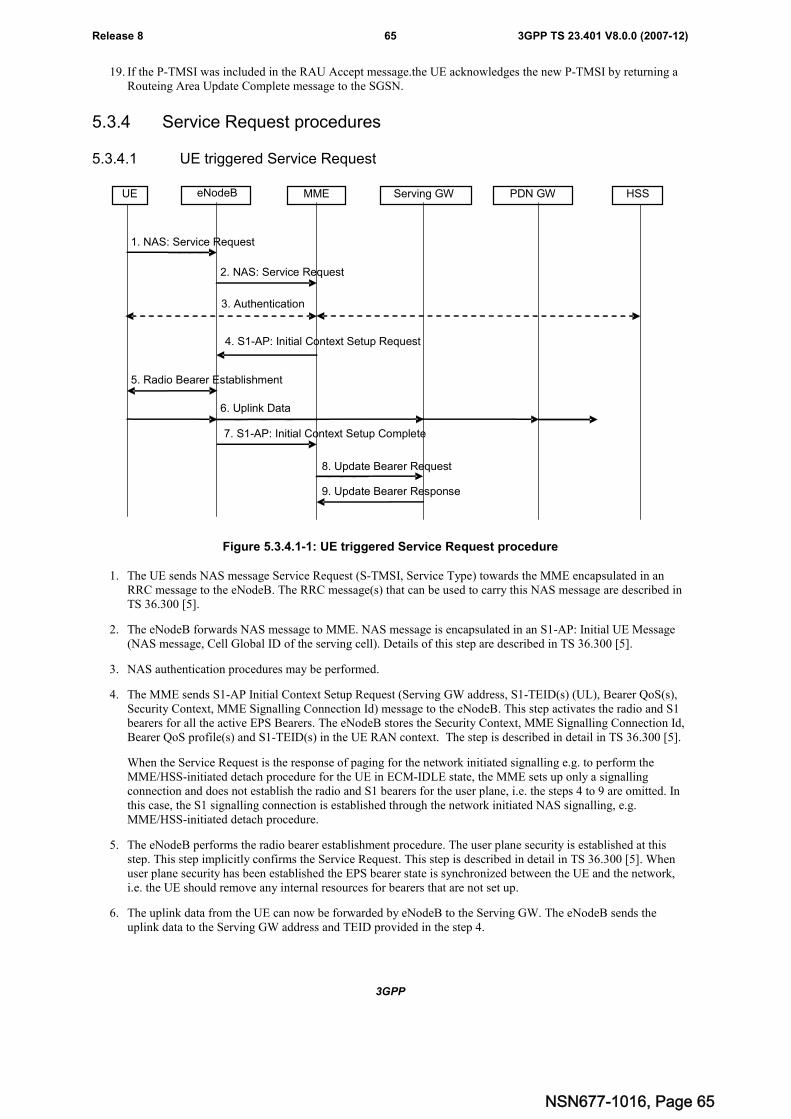
3GPP
3GPP TS 23.401 V8.0.0 (2007-12)65Release 8
19. If the P-TMSI was included in the RAU Accept message.the UE acknowledges the new P-TMSI by returning aRouteing Area Update Complete message to the SGSN.
5.3.4 Service Request procedures
5.3.4.1 UE triggered Service Request
MME Serving GW PDN GW
2. NAS: Service Request
1. NAS: Service Request
7. S1-AP: Initial Context Setup Complete
3. Authentication
HSS
4. S1-AP: Initial Context Setup Request
5. Radio Bearer Establishment
6. Uplink Data
8. Update Bearer Request
9. Update Bearer Response
UE eNodeB
Figure 5.3.4.1-1: UE triggered Service Request procedure
1. The UE sends NAS message Service Request (S-TMSI, Service Type) towards the MME encapsulated in anRRC message to the eNodeB. The RRC message(s) that can be used to carry this NAS message are described inTS 36.300 [5].
2. The eNodeB forwards NAS message to MME. NAS message is encapsulated in an S1-AP: Initial UE Message(NAS message, Cell Global ID of the serving cell). Details of this step are described in TS 36.300 [5].
3. NAS authentication procedures may be performed.
4. The MME sends S1-AP Initial Context Setup Request (Serving GW address, S1-TEID(s) (UL), Bearer QoS(s),Security Context, MME Signalling Connection Id) message to the eNodeB. This step activates the radio and S1bearers for all the active EPS Bearers. The eNodeB stores the Security Context, MME Signalling Connection Id,Bearer QoS profile(s) and S1-TEID(s) in the UE RAN context. The step is described in detail in TS 36.300 [5].
When the Service Request is the response of paging for the network initiated signalling e.g. to perform theMME/HSS-initiated detach procedure for the UE in ECM-IDLE state, the MME sets up only a signallingconnection and does not establish the radio and S1 bearers for the user plane, i.e. the steps 4 to 9 are omitted. Inthis case, the S1 signalling connection is established through the network initiated NAS signalling, e.g.MME/HSS-initiated detach procedure.
5. The eNodeB performs the radio bearer establishment procedure. The user plane security is established at thisstep. This step implicitly confirms the Service Request. This step is described in detail in TS 36.300 [5]. Whenuser plane security has been established the EPS bearer state is synchronized between the UE and the network,i.e. the UE should remove any internal resources for bearers that are not set up.
6. The uplink data from the UE can now be forwarded by eNodeB to the Serving GW. The eNodeB sends theuplink data to the Serving GW address and TEID provided in the step 4.
NSN677-1016, Page 65
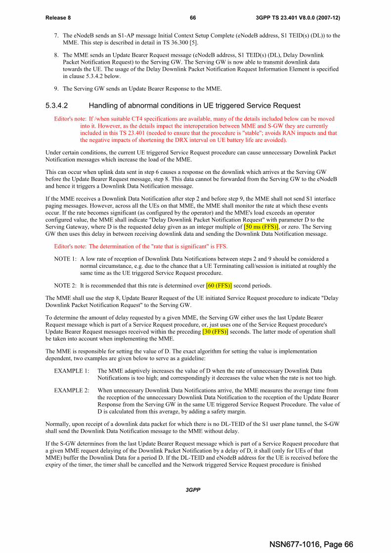
3GPP
3GPP TS 23.401 V8.0.0 (2007-12)66Release 8
7. The eNodeB sends an S1-AP message Initial Context Setup Complete (eNodeB address, S1 TEID(s) (DL)) to theMME. This step is described in detail in TS 36.300 [5].
8. The MME sends an Update Bearer Request message (eNodeB address, S1 TEID(s) (DL), Delay DownlinkPacket Notification Request) to the Serving GW. The Serving GW is now able to transmit downlink datatowards the UE. The usage of the Delay Downlink Packet Notification Request Information Element is specifiedin clause 5.3.4.2 below.
9. The Serving GW sends an Update Bearer Response to the MME.
5.3.4.2 Handling of abnormal conditions in UE triggered Service Request
Editor's note: If /when suitable CT4 specifications are available, many of the details included below can be movedinto it. However, as the details impact the interoperation between MME and S-GW they are currentlyincluded in this TS 23.401 (needed to ensure that the procedure is "stable"; avoids RAN impacts and thatthe negative impacts of shortening the DRX interval on UE battery life are avoided).
Under certain conditions, the current UE triggered Service Request procedure can cause unnecessary Downlink PacketNotification messages which increase the load of the MME.
This can occur when uplink data sent in step 6 causes a response on the downlink which arrives at the Serving GWbefore the Update Bearer Request message, step 8. This data cannot be forwarded from the Serving GW to the eNodeBand hence it triggers a Downlink Data Notification message.
If the MME receives a Downlink Data Notification after step 2 and before step 9, the MME shall not send S1 interfacepaging messages. However, across all the UEs on that MME, the MME shall monitor the rate at which these eventsoccur. If the rate becomes significant (as configured by the operator) and the MME's load exceeds an operatorconfigured value, the MME shall indicate "Delay Downlink Packet Notification Request" with parameter D to theServing Gateway, where D is the requested delay given as an integer multiple of [50 ms (FFS)], or zero. The ServingGW then uses this delay in between receiving downlink data and sending the Downlink Data Notification message.
Editor's note: The determination of the "rate that is significant" is FFS.
NOTE 1: A low rate of reception of Downlink Data Notifications between steps 2 and 9 should be considered anormal circumstance, e.g. due to the chance that a UE Terminating call/session is initiated at roughly thesame time as the UE triggered Service Request procedure.
NOTE 2: It is recommended that this rate is determined over [60 (FFS)] second periods.
The MME shall use the step 8, Update Bearer Request of the UE initiated Service Request procedure to indicate "DelayDownlink Packet Notification Request" to the Serving GW.
To determine the amount of delay requested by a given MME, the Serving GW either uses the last Update BearerRequest message which is part of a Service Request procedure, or, just uses one of the Service Request procedure'sUpdate Bearer Request messages received within the preceding [30 (FFS)] seconds. The latter mode of operation shallbe taken into account when implementing the MME.
The MME is responsible for setting the value of D. The exact algorithm for setting the value is implementationdependent, two examples are given below to serve as a guideline:
EXAMPLE 1: The MME adaptively increases the value of D when the rate of unnecessary Downlink DataNotifications is too high; and correspondingly it decreases the value when the rate is not too high.
EXAMPLE 2: When unnecessary Downlink Data Notifications arrive, the MME measures the average time fromthe reception of the unnecessary Downlink Data Notification to the reception of the Update BearerResponse from the Serving GW in the same UE triggered Service Request Procedure. The value ofD is calculated from this average, by adding a safety margin.
Normally, upon receipt of a downlink data packet for which there is no DL-TEID of the S1 user plane tunnel, the S-GWshall send the Downlink Data Notification message to the MME without delay.
If the S-GW determines from the last Update Bearer Request message which is part of a Service Request procedure thata given MME request delaying of the Downlink Packet Notification by a delay of D, it shall (only for UEs of thatMME) buffer the Downlink Data for a period D. If the DL-TEID and eNodeB address for the UE is received before theexpiry of the timer, the timer shall be cancelled and the Network triggered Service Request procedure is finished
NSN677-1016, Page 66
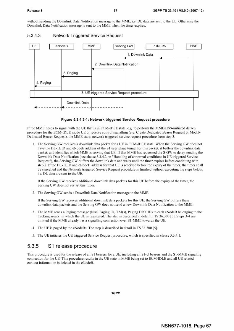
3GPP
3GPP TS 23.401 V8.0.0 (2007-12)67Release 8
without sending the Downlink Data Notification message to the MME, i.e. DL data are sent to the UE. Otherwise theDownlink Data Notification message is sent to the MME when the timer expires.
5.3.4.3 Network Triggered Service Request
1. Downlink Data
2. Downlink Data Notification
MME Serving GW PDN GW
3. Paging
4. Paging
HSS
5. UE triggered Service Request procedure
Downlink Data
UE eNodeB
Figure 5.3.4.3-1: Network triggered Service Request procedure
If the MME needs to signal with the UE that is in ECM-IDLE state, e.g. to perform the MME/HSS-initiated detachprocedure for the ECM-IDLE mode UE or receive control signalling (e.g. Create Dedicated Bearer Request or ModifyDedicated Bearer Request), the MME starts network triggered service request procedure from step 3.
1. The Serving GW receives a downlink data packet for a UE in ECM-IDLE state. When the Serving GW does nothave the DL-TEID and eNodeB address of the S1 user plane tunnel for this packet, it buffers the downlink datapacket. and identifies which MME is serving that UE. If that MME has requested the S-GW to delay sending theDownlink Data Notification (see clause 5.3.4.2 on "Handling of abnormal conditions in UE triggered ServiceRequest"), the Serving GW buffers the downlink data and waits until the timer expires before continuing withstep 2. If the DL-TEID and eNodeB address for that UE is received before the expiry of the timer, the timer shallbe cancelled and the Network triggered Service Request procedure is finished without executing the steps below,i.e. DL data are sent to the UE.
If the Serving GW receives additional downlink data packets for this UE before the expiry of the timer, theServing GW does not restart this timer.
2. The Serving GW sends a Downlink Data Notification message to the MME.
If the Serving GW receives additional downlink data packets for this UE, the Serving GW buffers thesedownlink data packets and the Serving GW does not send a new Downlink Data Notification to the MME.
3. The MME sends a Paging message (NAS Paging ID, TAI(s), Paging DRX ID) to each eNodeB belonging to thetracking area(s) in which the UE is registered. The step is described in detail in TS 36.300 [5]. Steps 3-4 areomitted if the MME already has a signalling connection over S1-MME towards the UE.
4. The UE is paged by the eNodeBs. The step is described in detail in TS 36.300 [5].
5. The UE initiates the UE triggered Service Request procedure, which is specified in clause 5.3.4.1.
5.3.5 S1 release procedure
This procedure is used for the release of all S1 bearers for a UE, including all S1-U bearers and the S1-MME signalingconnection for the UE. This procedure results in the UE state in MME being set to ECM-IDLE and all UE relatedcontext information is deleted in the eNodeB.
NSN677-1016, Page 67
3GPP
3GPP TS 23.401 V8.0.0 (2007-12)68Release 8
The initiation of S1 Release procedure is either:
- eNodeB-initiated with cause e.g. O&M Intervention, Unspecified Failure, User Inactivity, Repeated RRCsignalling Integrity Check Failure, Release due to UE generated signalling connection release, etc.; or
- MME-initiated with cause e.g. authentication failure, detach, etc.
Both eNodeB-initiated and MME-initiated S1 release procedures are shown in Figure 5.3.5-1.
1. S1-AP: S1 Release Request
MME
7. S1-AP: S1 Release Complete
5. Release RRC Connection
UE eNodeB
4. S1-AP: S1 Release Command
6. Release RRC Connection Ack
Serving GW
2. Update Bearer Request
3. Update Bearer Response
Figure 5.3.5-1: S1 Release Procedure
1. If the eNodeB detects a need to release the UE's signalling connection and all radio bearers for the UE, theeNodeB sends an S1 Release Request (Cause) message to the MME. Cause indicates the reason for the release(e.g. O&M intervention, unspecified failure, user inactivity, repeated integrity checking failure, or release due toUE generated signalling connection release).
NOTE: Step 1 is only performed when the eNodeB-initiated S1 release procedure is considered. Step 1 is notperformed and the procedure starts with Step 2 when the MME-initiated S1 release procedure isconsidered.
2. The MME sends an Update Bearer Request message to the S-GW that requests the release of all S1-U bearers forthe UE. This message is triggered either by an S1 Release Request message from the eNodeB, or by anotherMME event.
3. The S-GW releases all eNodeB related information (address and TEIDs) for the UE, sets the UE's ECM status toECM-IDLE and responds with an Update Bearer Response message to the MME. Other elements of the UE's S-GW context are not affected. The S-GW retains the S1-U configuration that the S-GW allocated for the UE'sbearers. The S-GW starts buffering downlink packets received for the UE and initiating the "Network TriggeredService Request" procedure, described in sub-clause 5.3.4.3, if downlink packets arrive for the UE.
4. The MME releases S1 by sending the S1 Release Command (Cause) message to the eNodeB.
5. If the RRC connection is not already released, the eNodeB sends a Release RRC Connection message to the UE.
6. The UE returns a Release RRC Connection Acknowledge message to the eNodeB. In the situation that the RRCconnection has not yet been successfully released, the eNodeB shall keep sufficient UE context information tocomplete the RRC connection release with the UE. When the RRC connection is released successfully, theeNodeB deletes the UE's context.
7. This step shall be performed promptly after step 4, e.g. it shall not be delayed in situations where the eNodeBdoes not receive a Release RRC Connection Acknowledge from the UE.
The eNodeB confirms the S1 Release by returning an S1 Release Complete message to the MME. With this, thesignalling connection between the MME and the eNodeB for that UE is released.
NSN677-1016, Page 68
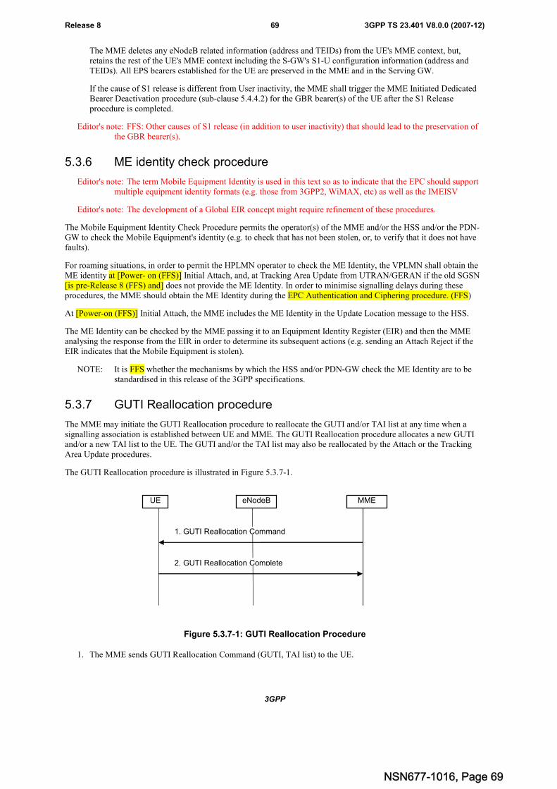
3GPP
3GPP TS 23.401 V8.0.0 (2007-12)69Release 8
The MME deletes any eNodeB related information (address and TEIDs) from the UE's MME context, but,retains the rest of the UE's MME context including the S-GW's S1-U configuration information (address andTEIDs). All EPS bearers established for the UE are preserved in the MME and in the Serving GW.
If the cause of S1 release is different from User inactivity, the MME shall trigger the MME Initiated DedicatedBearer Deactivation procedure (sub-clause 5.4.4.2) for the GBR bearer(s) of the UE after the S1 Releaseprocedure is completed.
Editor's note: FFS: Other causes of S1 release (in addition to user inactivity) that should lead to the preservation ofthe GBR bearer(s).
5.3.6 ME identity check procedure
Editor's note: The term Mobile Equipment Identity is used in this text so as to indicate that the EPC should supportmultiple equipment identity formats (e.g. those from 3GPP2, WiMAX, etc) as well as the IMEISV
Editor's note: The development of a Global EIR concept might require refinement of these procedures.
The Mobile Equipment Identity Check Procedure permits the operator(s) of the MME and/or the HSS and/or the PDN-GW to check the Mobile Equipment's identity (e.g. to check that has not been stolen, or, to verify that it does not havefaults).
For roaming situations, in order to permit the HPLMN operator to check the ME Identity, the VPLMN shall obtain theME identity at [Power- on (FFS)] Initial Attach, and, at Tracking Area Update from UTRAN/GERAN if the old SGSN[is pre-Release 8 (FFS) and] does not provide the ME Identity. In order to minimise signalling delays during theseprocedures, the MME should obtain the ME Identity during the EPC Authentication and Ciphering procedure. (FFS)
At [Power-on (FFS)] Initial Attach, the MME includes the ME Identity in the Update Location message to the HSS.
The ME Identity can be checked by the MME passing it to an Equipment Identity Register (EIR) and then the MMEanalysing the response from the EIR in order to determine its subsequent actions (e.g. sending an Attach Reject if theEIR indicates that the Mobile Equipment is stolen).
NOTE: It is FFS whether the mechanisms by which the HSS and/or PDN-GW check the ME Identity are to bestandardised in this release of the 3GPP specifications.
5.3.7 GUTI Reallocation procedure
The MME may initiate the GUTI Reallocation procedure to reallocate the GUTI and/or TAI list at any time when asignalling association is established between UE and MME. The GUTI Reallocation procedure allocates a new GUTIand/or a new TAI list to the UE. The GUTI and/or the TAI list may also be reallocated by the Attach or the TrackingArea Update procedures.
The GUTI Reallocation procedure is illustrated in Figure 5.3.7-1.
MMEeNodeBUE
1. GUTI Reallocation Command
2. GUTI Reallocation Complete
Figure 5.3.7-1: GUTI Reallocation Procedure
1. The MME sends GUTI Reallocation Command (GUTI, TAI list) to the UE.
NSN677-1016, Page 69
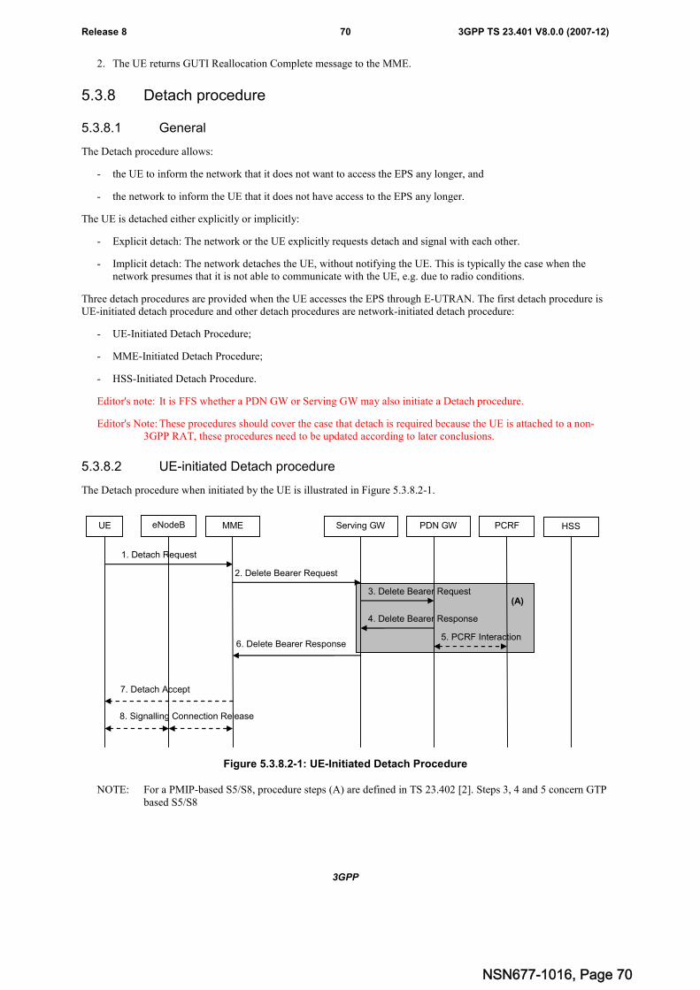
3GPP
3GPP TS 23.401 V8.0.0 (2007-12)70Release 8
2. The UE returns GUTI Reallocation Complete message to the MME.
5.3.8 Detach procedure
5.3.8.1 General
The Detach procedure allows:
- the UE to inform the network that it does not want to access the EPS any longer, and
- the network to inform the UE that it does not have access to the EPS any longer.
The UE is detached either explicitly or implicitly:
- Explicit detach: The network or the UE explicitly requests detach and signal with each other.
- Implicit detach: The network detaches the UE, without notifying the UE. This is typically the case when thenetwork presumes that it is not able to communicate with the UE, e.g. due to radio conditions.
Three detach procedures are provided when the UE accesses the EPS through E-UTRAN. The first detach procedure isUE-initiated detach procedure and other detach procedures are network-initiated detach procedure:
- UE-Initiated Detach Procedure;
- MME-Initiated Detach Procedure;
- HSS-Initiated Detach Procedure.
Editor's note: It is FFS whether a PDN GW or Serving GW may also initiate a Detach procedure.
Editor's Note: These procedures should cover the case that detach is required because the UE is attached to a non-3GPP RAT, these procedures need to be updated according to later conclusions.
5.3.8.2 UE-initiated Detach procedure
The Detach procedure when initiated by the UE is illustrated in Figure 5.3.8.2-1.
(A)
UE eNodeB MME Serving GW PDN GW PCRF
1. Detach Request
2. Delete Bearer Request
3. Delete Bearer Request
4. Delete Bearer Response
6. Delete Bearer Response
7. Detach Accept
5. PCRF Interaction
8. Signalling Connection Release
HSS
Figure 5.3.8.2-1: UE-Initiated Detach Procedure
NOTE: For a PMIP-based S5/S8, procedure steps (A) are defined in TS 23.402 [2]. Steps 3, 4 and 5 concern GTPbased S5/S8
NSN677-1016, Page 70
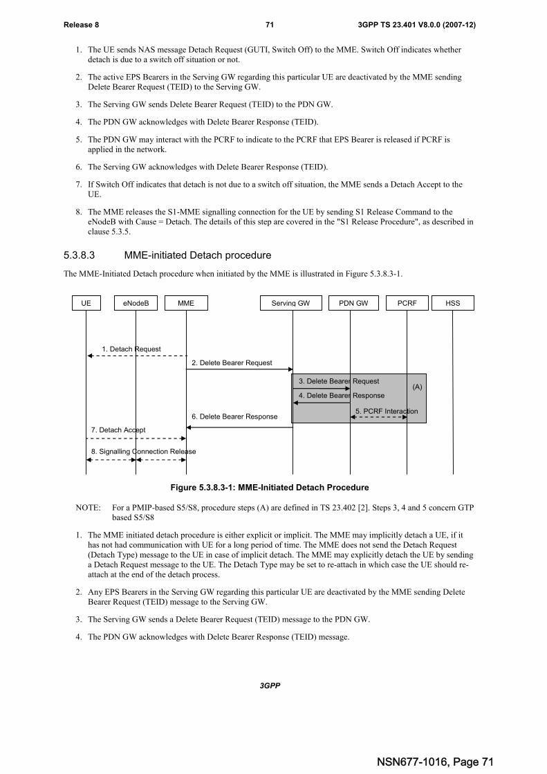
3GPP
3GPP TS 23.401 V8.0.0 (2007-12)71Release 8
1. The UE sends NAS message Detach Request (GUTI, Switch Off) to the MME. Switch Off indicates whetherdetach is due to a switch off situation or not.
2. The active EPS Bearers in the Serving GW regarding this particular UE are deactivated by the MME sendingDelete Bearer Request (TEID) to the Serving GW.
3. The Serving GW sends Delete Bearer Request (TEID) to the PDN GW.
4. The PDN GW acknowledges with Delete Bearer Response (TEID).
5. The PDN GW may interact with the PCRF to indicate to the PCRF that EPS Bearer is released if PCRF isapplied in the network.
6. The Serving GW acknowledges with Delete Bearer Response (TEID).
7. If Switch Off indicates that detach is not due to a switch off situation, the MME sends a Detach Accept to theUE.
8. The MME releases the S1-MME signalling connection for the UE by sending S1 Release Command to theeNodeB with Cause = Detach. The details of this step are covered in the "S1 Release Procedure", as described inclause 5.3.5.
5.3.8.3 MME-initiated Detach procedure
The MME-Initiated Detach procedure when initiated by the MME is illustrated in Figure 5.3.8.3-1.
UE eNodeB MME Serving GW PDN GW PCRF HSS
1. Detach Request
2. Delete Bearer Request
3. Delete Bearer Request
4. Delete Bearer Response
6. Delete Bearer Response
7. Detach Accept
8. Signalling Connection Release
(A)
5. PCRF Interaction
Figure 5.3.8.3-1: MME-Initiated Detach Procedure
NOTE: For a PMIP-based S5/S8, procedure steps (A) are defined in TS 23.402 [2]. Steps 3, 4 and 5 concern GTPbased S5/S8
1. The MME initiated detach procedure is either explicit or implicit. The MME may implicitly detach a UE, if ithas not had communication with UE for a long period of time. The MME does not send the Detach Request(Detach Type) message to the UE in case of implicit detach. The MME may explicitly detach the UE by sendinga Detach Request message to the UE. The Detach Type may be set to re-attach in which case the UE should re-attach at the end of the detach process.
2. Any EPS Bearers in the Serving GW regarding this particular UE are deactivated by the MME sending DeleteBearer Request (TEID) message to the Serving GW.
3. The Serving GW sends a Delete Bearer Request (TEID) message to the PDN GW.
4. The PDN GW acknowledges with Delete Bearer Response (TEID) message.
NSN677-1016, Page 71

3GPP
3GPP TS 23.401 V8.0.0 (2007-12)72Release 8
5. The PDN GW may interact with the PCRF to indicate to the PCRF that the EPS Bearer(s) are released if a PCRFis configured.
6. The Serving GW acknowledges with Delete Bearer Response (TEID) message.
7. If the UE receives the Detach Request message from the MME in the step 1, the UE sends a Detach Acceptmessage to the MME any time after step 1.
8. After receiving the Detach Accept message, if Detach Type did not request the UE to make a new attach, theMME releases the S1-MME signalling connection for the UE by sending an S1 Release Command (Cause)message to the eNodeB with Cause set to Detach. The details of this step are covered in the "S1 ReleaseProcedure", as described in clause 5.3.5.
5.3.8.4 HSS-initiated Detach procedure
The HSS-Initiated Detach procedure is initiated by the HSS. The HSS uses this procedure for operator-determinedpurposes to request the removal of a subscriber's MM and EPS bearer at the MME.
It is FFS, if the HSS initiates a detach procedure to update the subscriber's MM context at the MME and to delete theEPS bearer because that the UE's accessing RAT is changed from 3GPP to Non-3GPP.
The HSS-Initiated Detach Procedure is illustrated in Figure 5.3.8.4-1.
(A)
UE eNodeB MME Serving GW PDN GW PCRF HSS
2. Detach Request
3. Delete Bearer Request
4. Delete Bearer Request
5. Delete Bearer Response
7. Delete Bearer Response
8. Detach Accept
6. PCRF Interaction
10. Signalling Connection Release
1. Cancel Location
9. Cancel Location Ack
Figure 5.3.8.4-1: HSS-Initiated Detach Procedure
NOTE 1: For a PMIP-based S5/S8, procedure steps (A) are defined in TS 23.402 [2]. Steps 4, 5 and 6 concern GTPbased S5/S8.
1. If the HSS wants to request the immediate deletion of a subscriber's MM contexts and EPS Bearers, the HSSshall send a Cancel Location (IMSI, Cancellation Type) message to the MME with Cancellation Type set toSubscription Withdrawn.
It is FFS whether the Cancellation type can be set to "implicit detach because of UE's accessing RAT changed from3GPP to Non-3GPP".
2. If Cancellation Type is Subscription Withdrawn, the MME informs the UE, that it has been detached, by sendingDetach Request message to the UE.
3. The EPS Bearers in the Serving GW regarding this particular UE are deactivated by the MME sending a DeleteBearer Request (TEID) message to the Serving GW.
4. The Serving GW sends Delete Bearer Request (TEID) message to the PDN GW.
5. The PDN GW acknowledges with Delete Bearer Response (TEID) message.
NSN677-1016, Page 72
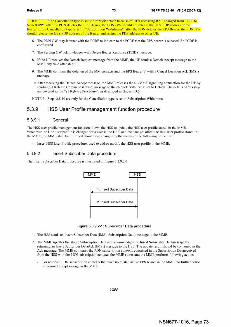
3GPP
3GPP TS 23.401 V8.0.0 (2007-12)73Release 8
It is FFS, If the Cancellation type is set to "implicit detach because of UE's accessing RAT changed from 3GPP toNon-3GPP", after the PDN deletes the EPS Bearer, the PDN GW should not release the UE's PDP address of theBearer. If the Cancellation type is set to "Subscription Withdrawn", after the PDN deletes the EPS Bearer, the PDN GWshould release the UE's PDP address of the Bearer and assign the PDP address to other UE.
6. The PDN GW may interact with the PCRF to indicate to the PCRF that the EPS bearer is released if a PCRF isconfigured.
7. The Serving GW acknowledges with Delete Bearer Response (TEID) message.
8. If the UE receives the Detach Request message from the MME, the UE sends a Detach Accept message to theMME any time after step 2.
9. The MME confirms the deletion of the MM contexts and the EPS Bearer(s) with a Cancel Location Ack (IMSI)message.
10. After receiving the Detach Accept message, the MME releases the S1-MME signalling connection for the UE bysending S1 Release Command (Cause) message to the eNodeB with Cause set to Detach. The details of this stepare covered in the "S1 Release Procedure", as described in clause 5.3.5.
NOTE 2: Steps 2,8,10 are only for the Cancellation type is set to Subscription Withdrawn.
5.3.9 HSS User Profile management function procedure
5.3.9.1 General
The HSS user profile management function allows the HSS to update the HSS user profile stored in the MME.Whenever the HSS user profile is changed for a user in the HSS, and the changes affect the HSS user profile stored inthe MME, the MME shall be informed about these changes by the means of the following procedure:
- Insert HSS User Profile procedure, used to add or modify the HSS user profile in the MME.
5.3.9.2 Insert Subscriber Data procedure
The Insert Subscriber Data procedure is illustrated in Figure 5.3.9.2-1.
HSSMME
1. Insert Subscriber Data
2. Insert Subscriber Data
Figure 5.3.9.2-1: Subscriber Data procedure
1. The HSS sends an Insert Subscriber Data (IMSI, Subscription Data) message to the MME.
2. The MME updates the stored Subscription Data and acknowledges the Insert Subscriber Datamessage byreturning an Insert Subscriber DataAck (IMSI) message to the HSS. The update result should be contained in theAck message. The MME compares the PDN subscription contexts contained in the Subscription Datareceivedfrom the HSS with the PDN subscription contexts the MME stores and the MME performs following action:
- For received PDN subscription contexts that have no related active EPS bearer in the MME, no further actionis required except storage in the MME.
NSN677-1016, Page 73
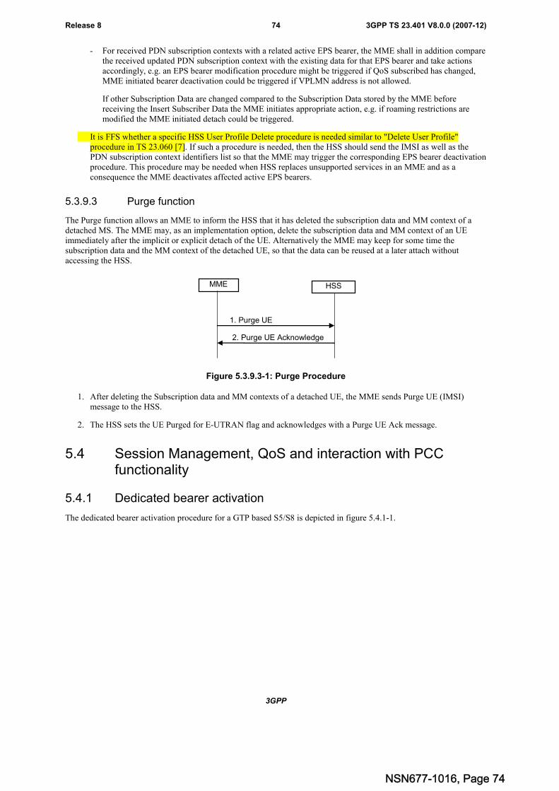
3GPP
3GPP TS 23.401 V8.0.0 (2007-12)74Release 8
- For received PDN subscription contexts with a related active EPS bearer, the MME shall in addition comparethe received updated PDN subscription context with the existing data for that EPS bearer and take actionsaccordingly, e.g. an EPS bearer modification procedure might be triggered if QoS subscribed has changed,MME initiated bearer deactivation could be triggered if VPLMN address is not allowed.
If other Subscription Data are changed compared to the Subscription Data stored by the MME beforereceiving the Insert Subscriber Data the MME initiates appropriate action, e.g. if roaming restrictions aremodified the MME initiated detach could be triggered.
It is FFS whether a specific HSS User Profile Delete procedure is needed similar to "Delete User Profile"procedure in TS 23.060 [7]. If such a procedure is needed, then the HSS should send the IMSI as well as thePDN subscription context identifiers list so that the MME may trigger the corresponding EPS bearer deactivationprocedure. This procedure may be needed when HSS replaces unsupported services in an MME and as aconsequence the MME deactivates affected active EPS bearers.
5.3.9.3 Purge function
The Purge function allows an MME to inform the HSS that it has deleted the subscription data and MM context of adetached MS. The MME may, as an implementation option, delete the subscription data and MM context of an UEimmediately after the implicit or explicit detach of the UE. Alternatively the MME may keep for some time thesubscription data and the MM context of the detached UE, so that the data can be reused at a later attach withoutaccessing the HSS.
MME HSS
1. Purge UE
2. Purge UE Acknowledge
Figure 5.3.9.3-1: Purge Procedure
1. After deleting the Subscription data and MM contexts of a detached UE, the MME sends Purge UE (IMSI)message to the HSS.
2. The HSS sets the UE Purged for E-UTRAN flag and acknowledges with a Purge UE Ack message.
5.4 Session Management, QoS and interaction with PCCfunctionality
5.4.1 Dedicated bearer activation
The dedicated bearer activation procedure for a GTP based S5/S8 is depicted in figure 5.4.1-1.
NSN677-1016, Page 74
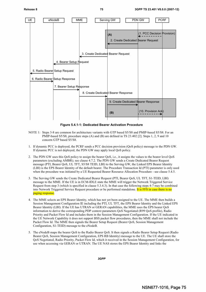
3GPP
3GPP TS 23.401 V8.0.0 (2007-12)75Release 8
(1. PCC Decision Provision)
3. Create Dedicated Bearer Request
MME Serving GW PDN GW PCRF
4. Bearer Setup Request
5. Radio Bearer Setup Request
2. Create Dedicated Bearer Request
6. Radio Bearer Setup Response
7. Bearer Setup Response
8. Create Dedicated Bearer Response
(10. Provision Ack)
eNodeBUE
(A)
(B)
9. Create Dedicated Bearer Response
Figure 5.4.1-1: Dedicated Bearer Activation Procedure
NOTE 1: Steps 3-8 are common for architecture variants with GTP based S5/S8 and PMIP-based S5/S8. For anPMIP-based S5/S8, procedure steps (A) and (B) are defined in TS 23.402 [2]. Steps 1, 2, 9 and 10concern GTP based S5/S8.
1. If dynamic PCC is deployed, the PCRF sends a PCC decision provision (QoS policy) message to the PDN GW.If dynamic PCC is not deployed, the PDN GW may apply local QoS policy.
2. The PDN GW uses this QoS policy to assign the bearer QoS, i.e., it assigns the values to the bearer level QoSparameters (excluding AMBR); see clause 4.7.2. The PDN GW sends a Create Dedicated Bearer Requestmessage (PTI, Bearer QoS, UL TFT, S5/S8 TEID, LBI) to the Serving GW, the Linked EPS Bearer Identity(LBI) is the EPS Bearer Identity of the default bearer. The Procedure Transaction Id (PTI) parameter is only usedwhen the procedure was initiated by a UE Requested Bearer Resource Allocation Procedure - see clause 5.4.5.
3. The Serving GW sends the Create Dedicated Bearer Request (PTI, Bearer QoS, UL TFT, S1-TEID, LBI)message to the MME. If the UE is in ECM-IDLE state the MME will trigger the Network Triggered ServiceRequest from step 3 (which is specified in clause 5.3.4.3). In that case the following steps 4-7 may be combinedinto Network Triggered Service Request procedure or be performed standalone. It is FFS in case there is nopaging response.
4. The MME selects an EPS Bearer Identity, which has not yet been assigned to the UE. The MME then builds aSession Management Configuration IE including the PTI, UL TFT, the EPS Bearer Identity and the Linked EPSBearer Identity (LBI). If the UE has UTRAN or GERAN capabilities, the MME uses the EPS bearer QoSinformation to derive the corresponding PDP context parameters QoS Negotiated (R99 QoS profile), RadioPriority and Packet Flow Id and includes them in the Session Management Configuration. If the UE indicated inthe UE Network Capability it does not support BSS packet flow procedures, then the MME shall not include thePacket Flow Id. The MME then signals the Bearer Setup Request (Bearer QoS, Session ManagementConfiguration, S1-TEID) message to the eNodeB.
5. The eNodeB maps the bearer QoS to the Radio Bearer QoS. It then signals a Radio Bearer Setup Request (RadioBearer QoS, Session Management Configuration, EPS RB Identity) message to the UE. The UE shall store theQoS Negotiated, Radio Priority, Packet Flow Id, which it received in the Session Management Configuration, foruse when accessing via GERAN or UTRAN. The UE NAS stores the EPS Bearer Identity and links the
NSN677-1016, Page 75
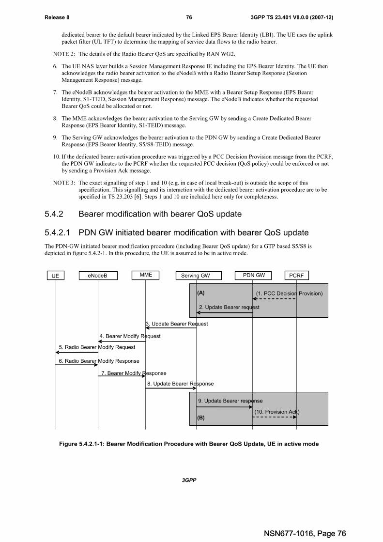
3GPP
3GPP TS 23.401 V8.0.0 (2007-12)76Release 8
dedicated bearer to the default bearer indicated by the Linked EPS Bearer Identity (LBI). The UE uses the uplinkpacket filter (UL TFT) to determine the mapping of service data flows to the radio bearer.
NOTE 2: The details of the Radio Bearer QoS are specified by RAN WG2.
6. The UE NAS layer builds a Session Management Response IE including the EPS Bearer Identity. The UE thenacknowledges the radio bearer activation to the eNodeB with a Radio Bearer Setup Response (SessionManagement Response) message.
7. The eNodeB acknowledges the bearer activation to the MME with a Bearer Setup Response (EPS BearerIdentity, S1-TEID, Session Management Response) message. The eNodeB indicates whether the requestedBearer QoS could be allocated or not.
8. The MME acknowledges the bearer activation to the Serving GW by sending a Create Dedicated BearerResponse (EPS Bearer Identity, S1-TEID) message.
9. The Serving GW acknowledges the bearer activation to the PDN GW by sending a Create Dedicated BearerResponse (EPS Bearer Identity, S5/S8-TEID) message.
10. If the dedicated bearer activation procedure was triggered by a PCC Decision Provision message from the PCRF,the PDN GW indicates to the PCRF whether the requested PCC decision (QoS policy) could be enforced or notby sending a Provision Ack message.
NOTE 3: The exact signalling of step 1 and 10 (e.g. in case of local break-out) is outside the scope of thisspecification. This signalling and its interaction with the dedicated bearer activation procedure are to bespecified in TS 23.203 [6]. Steps 1 and 10 are included here only for completeness.
5.4.2 Bearer modification with bearer QoS update
5.4.2.1 PDN GW initiated bearer modification with bearer QoS update
The PDN-GW initiated bearer modification procedure (including Bearer QoS update) for a GTP based S5/S8 isdepicted in figure 5.4.2-1. In this procedure, the UE is assumed to be in active mode.
(B)
(1. PCC Decision Provision)
3. Update Bearer Request
MME Serving GW PDN GW PCRF
4. Bearer Modify Request
5. Radio Bearer Modify Request
2. Update Bearer request
6. Radio Bearer Modify Response
7. Bearer Modify Response
8. Update Bearer Response
9. Update Bearer response
(10. Provision Ack)
UE eNodeB
(A)
Figure 5.4.2.1-1: Bearer Modification Procedure with Bearer QoS Update, UE in active mode
NSN677-1016, Page 76
3GPP
3GPP TS 23.401 V8.0.0 (2007-12)77Release 8
NOTE 1: Steps 3-8 are common for architecture variants with GTP based S5/S8 and PMIP-based S5/S8. For aPMIP-based S5/S8, procedure steps (A) and (B) are defined in TS 23.402 [2]. Steps 1, 2, 9 and 10concern GTP based S5/S8.
1. If dynamic PCC is not deployed, the PCRF sends a PCC decision provision (QoS policy) message to the PDNGW. If dynamic PCC is not deployed, the PDN GW may apply local QoS policy.
2. The PDN GW uses this QoS policy to determine that a service data flow shall be aggregated to or removed froman active bearer. The PDN GW generates the UL TFT and updates the Bearer QoS to match the aggregated set ofservice date flows. The PDN GW then sends the Update Bearer Request (PTI, EPS Bearer Identity, Bearer QoS,UL TFT) message to the Serving GW. The Procedure Transaction Id (PTI) parameter is used when the procedurewas initiated by a UE Requested Bearer Resource Allocation Procedure - see clause 5.4.5 or is used when theprocedure was initiated by a UE Requested Bearer Resource Release Procedure - see clause 5.4.6.
3. The Serving GW sends the Update Bearer Request (PTI, EPS Bearer Identity, Bearer QoS, UL TFT) message tothe MME.
4. The MME builds a Session Management Configuration IE including the PTI and the UL TFT and EPS BearerIdentity. If the UE has UTRAN or GERAN capabilities, the MME uses the EPS bearer QoS information toderive the corresponding PDP context parameters QoS Negotiated (R99 QoS profile), Radio Priority and PacketFlow Id and includes them in the Session Management Configuration. If the UE indicated in the UE NetworkCapability it does not support BSS packet flow procedures, then the MME shall not include the Packet Flow Id.The MME then sends the Bearer Modify Request (EPS Bearer Identity, Bearer QoS, Session ManagementConfiguration) message to the eNodeB.
5. The eNodeB maps the modified Bearer QoS to the Radio Bearer QoS. It then signals a Radio Bearer ModifyRequest (Radio Bearer QoS, Session Management Configuration, EPS RB Identity) message to the UE. The UEshall store the QoS Negotiated, Radio Priority, Packet Flow Id, which it received in the Session ManagementConfiguration, for use when accessing via GERAN or UTRAN. The UE uses the uplink packet filter (UL TFT)to determine the mapping of service data flows to the radio bearer.
NOTE 2: The details of the Radio Bearer QoS are specified by RAN WG2.
6. The UE NAS layer builds a Session Management Response IE including EPS Bearer Identity. The UE thenacknowledges the radio bearer modification to the eNodeB with a Radio Bearer Modify Response (SessionManagement Response).message.
7. The eNodeB acknowledges the bearer modification to the MME with a Bearer Modify Response (EPS BearerIdentity, Session Management Response) message. With this message, the eNodeB indicates whether therequested Bearer QoS could be allocated or not.
8. The MME acknowledges the bearer modification to the Serving GW by sending an Update Bearer Response(EPS Bearer Identity) message.
9. The Serving GW acknowledges the bearer modification to the PDN GW by sending an Update Bearer Response(EPS Bearer Identity) message.
Editor's Note: It is FFS whether the EPS Bearer Identity is needed in the Update Bearer Response message tocorrelate with the Update Bearer Request message.
10. If the Bearer modification procedure was triggered by a PCC Decision Provision message from the PCRF, thePDN GW indicates to the PCRF whether the requested PCC decision (QoS policy) could be enforced or not bysending a Provision Ack message.
NOTE 3: The exact signalling of step 1 and 10 (e.g. in case of local break-out) is outside the scope of thisspecification. This signalling and its interaction with the bearer activation procedure are to be specified inTS 23.203 [6]. Steps 1 and 10 are included here only for completeness.
5.4.2.2 MME Initiated Bearer Modification with Bearer QoS Update
The MME may initiate a bearer modification procedure to update the default bearer QoS and dedicated bearer QoS,(e.g. the subscribed Qos profile has been changed).
The MME Initiated Bearer Modification with Bearer QoS Update for a GTP-based S5/S8 is depicted in figure 5.4.2.2-1.
NSN677-1016, Page 77
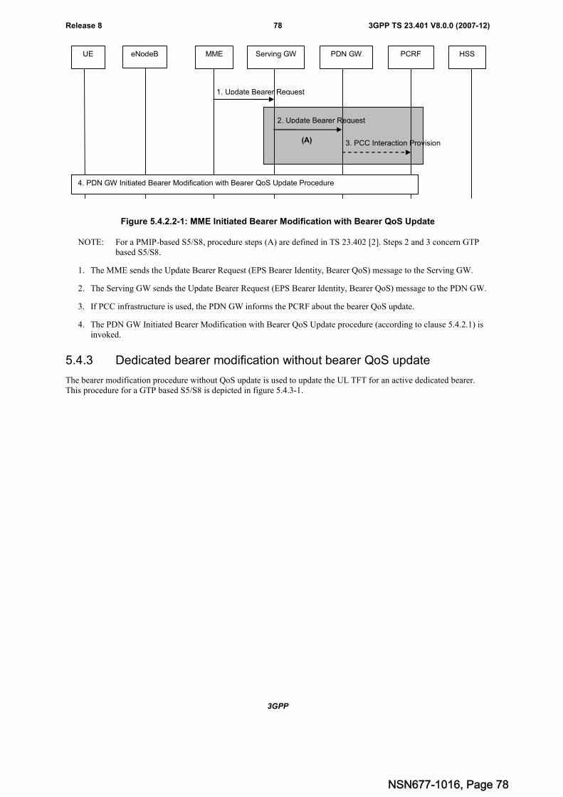
3GPP
3GPP TS 23.401 V8.0.0 (2007-12)78Release 8
(A)
UE eNodeB MME Serving GW PDN GW PCRF HSS
1. Update Bearer Request
2. Update Bearer Request
3. PCC Interaction Provision
4. PDN GW Initiated Bearer Modification with Bearer QoS Update Procedure
Figure 5.4.2.2-1: MME Initiated Bearer Modification with Bearer QoS Update
NOTE: For a PMIP-based S5/S8, procedure steps (A) are defined in TS 23.402 [2]. Steps 2 and 3 concern GTPbased S5/S8.
1. The MME sends the Update Bearer Request (EPS Bearer Identity, Bearer QoS) message to the Serving GW.
2. The Serving GW sends the Update Bearer Request (EPS Bearer Identity, Bearer QoS) message to the PDN GW.
3. If PCC infrastructure is used, the PDN GW informs the PCRF about the bearer QoS update.
4. The PDN GW Initiated Bearer Modification with Bearer QoS Update procedure (according to clause 5.4.2.1) isinvoked.
5.4.3 Dedicated bearer modification without bearer QoS update
The bearer modification procedure without QoS update is used to update the UL TFT for an active dedicated bearer.This procedure for a GTP based S5/S8 is depicted in figure 5.4.3-1.
NSN677-1016, Page 78
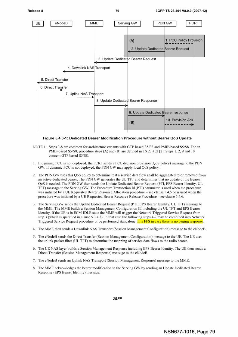
3GPP
3GPP TS 23.401 V8.0.0 (2007-12)79Release 8
(A) 1. PCC Policy Provision
3. Update Dedicated Bearer Request
MME Serving GW PDN GW PCRF
4. Downlink NAS Transport
5. Direct Transfer
2. Update Dedicated Bearer Request
6. Direct Transfer
7. Uplink NAS Transport
8. Update Dedicated Bearer Response
9. Update Dedicated Bearer response
10. Provision Ack
eNodeBUE
(B)
Figure 5.4.3-1: Dedicated Bearer Modification Procedure without Bearer QoS Update
NOTE 1: Steps 3-8 are common for architecture variants with GTP based S5/S8 and PMIP-based S5/S8. For anPMIP-based S5/S8, procedure steps (A) and (B) are defined in TS 23.402 [2]. Steps 1, 2, 9 and 10concern GTP based S5/S8.
1. If dynamic PCC is not deployed, the PCRF sends a PCC decision provision (QoS policy) message to the PDNGW. If dynamic PCC is not deployed, the PDN GW may apply local QoS policy.
2. The PDN GW uses this QoS policy to determine that a service data flow shall be aggregated to or removed froman active dedicated bearer. The PDN GW generates the UL TFT and determines that no update of the BearerQoS is needed. The PDN GW then sends the Update Dedicated Bearer Request (PTI, EPS Bearer Identity, ULTFT) message to the Serving GW. The Procedure Transaction Id (PTI) parameter is used when the procedurewas initiated by a UE Requested Bearer Resource Allocation procedure – see clause 5.4.5 or is used when theprocedure was initiated by a UE Requested Bearer Resource Release Procedure - see clause 5.4.6.
3. The Serving GW sends the Update Dedicated Bearer Request (PTI, EPS Bearer Identity, UL TFT) message tothe MME. The MME builds a Session Management Configuration IE including the UL TFT and EPS BearerIdentity. If the UE is in ECM-IDLE state the MME will trigger the Network Triggered Service Request fromstep 3 (which is specified in clause 5.3.4.3). In that case the following steps 4-7 may be combined into NetworkTriggered Service Request procedure or be performed standalone. It is FFS in case there is no paging response.
4. The MME then sends a Downlink NAS Transport (Session Management Configuration) message to the eNodeB.
5. The eNodeB sends the Direct Transfer (Session Management Configuration) message to the UE. The UE usesthe uplink packet filter (UL TFT) to determine the mapping of service data flows to the radio bearer.
6. The UE NAS layer builds a Session Management Response including EPS Bearer Identity. The UE then sends aDirect Transfer (Session Management Response) message to the eNodeB.
7. The eNodeB sends an Uplink NAS Transport (Session Management Response) message to the MME.
8. The MME acknowledges the bearer modification to the Serving GW by sending an Update Dedicated BearerResponse (EPS Bearer Identity) message.
NSN677-1016, Page 79
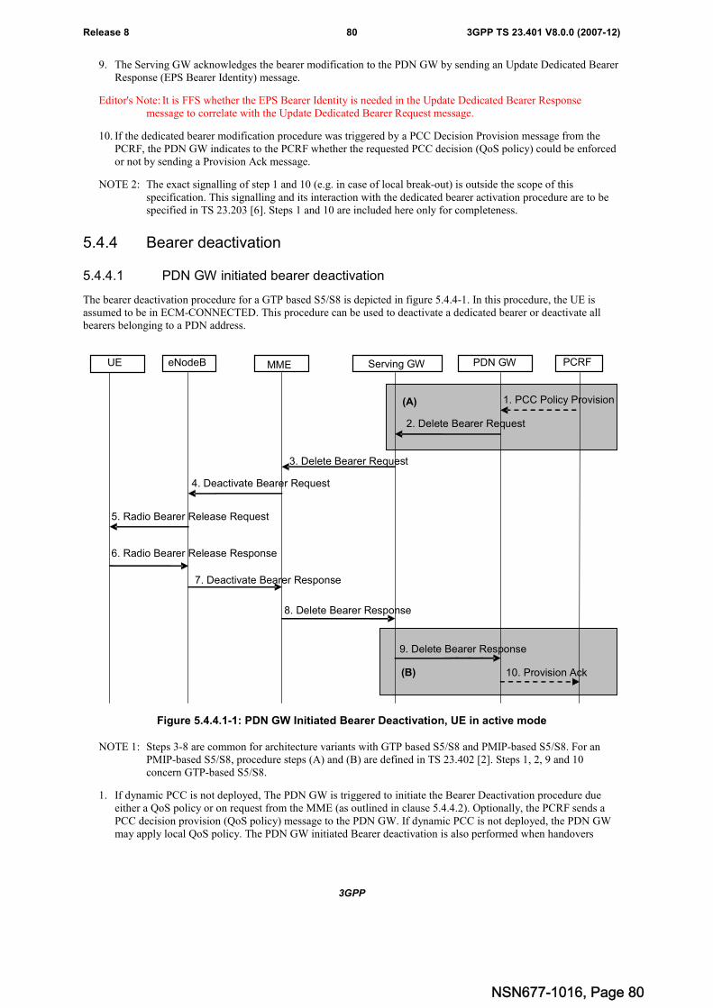
3GPP
3GPP TS 23.401 V8.0.0 (2007-12)80Release 8
9. The Serving GW acknowledges the bearer modification to the PDN GW by sending an Update Dedicated BearerResponse (EPS Bearer Identity) message.
Editor's Note: It is FFS whether the EPS Bearer Identity is needed in the Update Dedicated Bearer Responsemessage to correlate with the Update Dedicated Bearer Request message.
10. If the dedicated bearer modification procedure was triggered by a PCC Decision Provision message from thePCRF, the PDN GW indicates to the PCRF whether the requested PCC decision (QoS policy) could be enforcedor not by sending a Provision Ack message.
NOTE 2: The exact signalling of step 1 and 10 (e.g. in case of local break-out) is outside the scope of thisspecification. This signalling and its interaction with the dedicated bearer activation procedure are to bespecified in TS 23.203 [6]. Steps 1 and 10 are included here only for completeness.
5.4.4 Bearer deactivation
5.4.4.1 PDN GW initiated bearer deactivation
The bearer deactivation procedure for a GTP based S5/S8 is depicted in figure 5.4.4-1. In this procedure, the UE isassumed to be in ECM-CONNECTED. This procedure can be used to deactivate a dedicated bearer or deactivate allbearers belonging to a PDN address.
(B)
(A) 1. PCC Policy Provision
3. Delete Bearer Request
MME Serving GW PDN GW PCRF
4. Deactivate Bearer Request
5. Radio Bearer Release Request
2. Delete Bearer Request
6. Radio Bearer Release Response
7. Deactivate Bearer Response
8. Delete Bearer Response
9. Delete Bearer Response
10. Provision Ack
eNodeBUE
Figure 5.4.4.1-1: PDN GW Initiated Bearer Deactivation, UE in active mode
NOTE 1: Steps 3-8 are common for architecture variants with GTP based S5/S8 and PMIP-based S5/S8. For anPMIP-based S5/S8, procedure steps (A) and (B) are defined in TS 23.402 [2]. Steps 1, 2, 9 and 10concern GTP-based S5/S8.
1. If dynamic PCC is not deployed, The PDN GW is triggered to initiate the Bearer Deactivation procedure dueeither a QoS policy or on request from the MME (as outlined in clause 5.4.4.2). Optionally, the PCRF sends aPCC decision provision (QoS policy) message to the PDN GW. If dynamic PCC is not deployed, the PDN GWmay apply local QoS policy. The PDN GW initiated Bearer deactivation is also performed when handovers
NSN677-1016, Page 80
3GPP
3GPP TS 23.401 V8.0.0 (2007-12)81Release 8
without optimization occurs from 3GPP to non-3GPP, in which case, the default bearer and all the dedicatedbearers associated with the PDN address are released, but the PDN address is kept in the PDN GW.
2. The PDN GW sends a Delete Bearer Request (PTI, EPS Bearer Identity) message to the Serving GW. TheProcedure Transaction Id (PTI) parameter in this step and in the following steps is only used when the procedurewas initiated by a UE Requested Bearer Resource Release Procedure - see clause 5.4.6. This message caninclude an indication that all bearers belonging to that PDN connection shall be released.
3. The Serving GW sends the Delete Bearer Request (PTI, EPS Bearer Identity) message to the MME. Thismessage can include an indication that all bearers belonging to that PDN connection shall be released.
4. The MME builds a Session Management Configuration IE including the PTI, a Deletion Indicator and EPSBearer Identity. The MME then signals the Deactivate Bearer Request (EPS Bearer Identity, SessionManagement Configuration) message to the eNodeB.
5. The eNodeB signals a Radio Bearer Release Request (EPS RB Identity, Session Management Configuration)message to the UE.
6. The UE NAS removes the UL TFTs and EPS Bearer Identity according to the Session ManagementConfiguration. The UE NAS then layer builds a Session Management Response including the EPS BearerIdentity. The UE then acknowledges the radio bearer release to the eNodeB with a Radio Bearer ReleaseResponse (Session Management Response)message.
7. The eNodeB acknowledges the bearer deactivation to the MME with a Deactivate Bearer Response (EPS BearerIdentity, Session Management Response) message.
8. The MME deletes the bearer context related to the deactivated EPS bearer acknowledges the bearer deactivationto the Serving GW by sending a Delete Bearer Response (EPS Bearer Identity) message.
9. The Serving GW deletes the bearer context related to the deactivated EPS bearer acknowledges the bearerdeactivation to the PDN GW by sending a Delete Bearer Response (EPS Bearer Identity) message.
Editor's Note: It is FFS whether the EPS Bearer Identity is needed in the Delete Dedicated Bearer Response messageto correlate with the Delete Dedicated Bearer Request message.
10. The PDN GW deletes the bearer context related to the deactivated EPS bearer. If the dedicated bearerdeactivation procedure was triggered by a PCC Decision Provision message from the PCRF, the PDN GWindicates to the PCRF that the requested PCC decision was enforced by sending a Provision Ack message.
NOTE 2: The exact signalling of step 1 and 10 (e.g. in case of local break-out) is outside the scope of thisspecification. This signalling and its interaction with the dedicated bearer activation procedure are to bespecified in TS 23.203 [6]. Steps 1 and 10 are included here only for completeness.
Steps 4 to 7 are not performed when the UE is in ECM-IDLE. The EPS bearer state is synchronized between theUE and the network at the next ECM-IDLE to ECM-CONNECTED transition (e.g. Service Request or TAUprocedure).
If all the bearers belonging to a UE are released, the MME shall change the MM state of the UE to EMM-DEREGISTERED.
Editor's note: FFS: handling of steps 4 to 7 when the UE is in ECM-CONNECTED but not reachable.
5.4.4.2 MME Initiated Dedicated Bearer Deactivation
MME initiated Dedicated Bearer Deactivation is depicted in Figure 5.4.4-2 below. This procedure deactivates dedicatedbearers. Default bearers are not affected.
NSN677-1016, Page 81
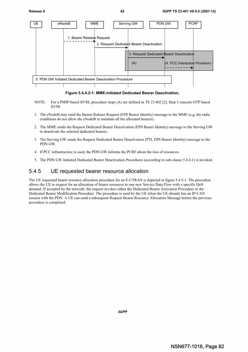
3GPP
3GPP TS 23.401 V8.0.0 (2007-12)82Release 8
(4. PCC Interaction Provision)
MME Serving GW PDN GW PCRF
2. Request Dedicated Bearer Deactivation
eNodeBUE
3. Request Dedicated Bearer Deactivation
5. PDN GW Initiated Dedicated Bearer Deactivation Procedure
1. Bearer Release Request
(A)
Figure 5.4.4.2-1: MME-initiated Dedicated Bearer Deactivation,
NOTE: For a PMIP-based S5/S8, procedure steps (A) are defined in TS 23.402 [2]. Step 3 concern GTP basedS5/S8
1. The eNodeB may send the Bearer Release Request (EPS Bearer Identity) message to the MME (e.g, the radioconditions do not allow the eNodeB to maintain all the allocated bearers).
2. The MME sends the Request Dedicated Bearer Deactivation (EPS Bearer Identity) message to the Serving GWto deactivate the selected dedicated bearers.
3. The Serving GW sends the Request Dedicated Bearer Deactivation (PTI, EPS Bearer Identity) message to thePDN GW.
4. If PCC infrastructure is used, the PDN GW informs the PCRF about the loss of resources.
5. The PDN GW Initiated Dedicated Bearer Deactivation Procedures (according to sub-clause 5.4.4.1) is invoked.
5.4.5 UE requested bearer resource allocation
The UE requested bearer resource allocation procedure for an E-UTRAN is depicted in figure 5.4.5-1. The procedureallows the UE to request for an allocation of bearer resources to one new Service Data Flow with a specific QoSdemand. If accepted by the network, the request invokes either the Dedicated Bearer Activation Procedure or theDedicated Bearer Modification Procedure. The procedure is used by the UE when the UE already has an IP-CANsession with the PDN. A UE can send a subsequent Request Bearer Resource Allocation Message before the previousprocedure is completed.
NSN677-1016, Page 82
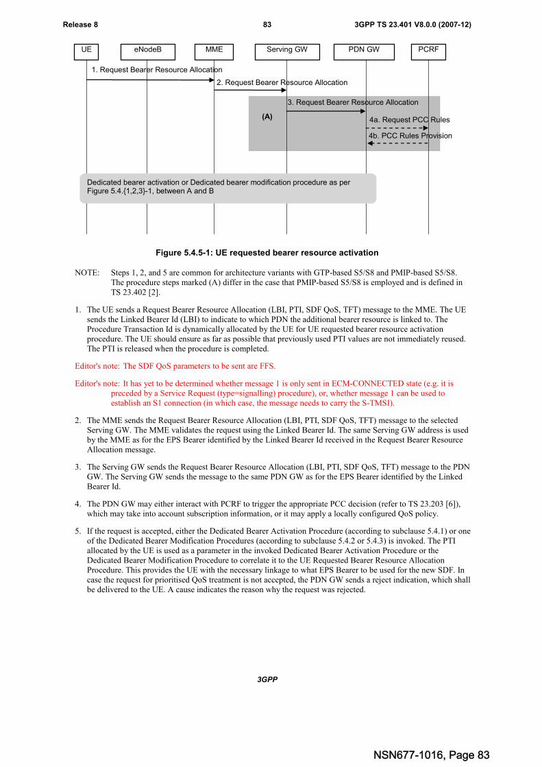
3GPP
3GPP TS 23.401 V8.0.0 (2007-12)83Release 8
MME Serving GW PDN GW PCRF
1. Request Bearer Resource Allocation
2. Request Bearer Resource Allocation
eNodeBUE
3. Request Bearer Resource Allocation
(A)
Dedicated bearer activation or Dedicated bearer modification procedure as perFigure 5.4.{1,2,3}-1, between A and B
4b. PCC Rules Provision
4a. Request PCC Rules
Figure 5.4.5-1: UE requested bearer resource activation
NOTE: Steps 1, 2, and 5 are common for architecture variants with GTP-based S5/S8 and PMIP-based S5/S8.The procedure steps marked (A) differ in the case that PMIP-based S5/S8 is employed and is defined inTS 23.402 [2].
1. The UE sends a Request Bearer Resource Allocation (LBI, PTI, SDF QoS, TFT) message to the MME. The UEsends the Linked Bearer Id (LBI) to indicate to which PDN the additional bearer resource is linked to. TheProcedure Transaction Id is dynamically allocated by the UE for UE requested bearer resource activationprocedure. The UE should ensure as far as possible that previously used PTI values are not immediately reused.The PTI is released when the procedure is completed.
Editor's note: The SDF QoS parameters to be sent are FFS.
Editor's note: It has yet to be determined whether message 1 is only sent in ECM-CONNECTED state (e.g. it ispreceded by a Service Request (type=signalling) procedure), or, whether message 1 can be used toestablish an S1 connection (in which case, the message needs to carry the S-TMSI).
2. The MME sends the Request Bearer Resource Allocation (LBI, PTI, SDF QoS, TFT) message to the selectedServing GW. The MME validates the request using the Linked Bearer Id. The same Serving GW address is usedby the MME as for the EPS Bearer identified by the Linked Bearer Id received in the Request Bearer ResourceAllocation message.
3. The Serving GW sends the Request Bearer Resource Allocation (LBI, PTI, SDF QoS, TFT) message to the PDNGW. The Serving GW sends the message to the same PDN GW as for the EPS Bearer identified by the LinkedBearer Id.
4. The PDN GW may either interact with PCRF to trigger the appropriate PCC decision (refer to TS 23.203 [6]),which may take into account subscription information, or it may apply a locally configured QoS policy.
5. If the request is accepted, either the Dedicated Bearer Activation Procedure (according to subclause 5.4.1) or oneof the Dedicated Bearer Modification Procedures (according to subclause 5.4.2 or 5.4.3) is invoked. The PTIallocated by the UE is used as a parameter in the invoked Dedicated Bearer Activation Procedure or theDedicated Bearer Modification Procedure to correlate it to the UE Requested Bearer Resource AllocationProcedure. This provides the UE with the necessary linkage to what EPS Bearer to be used for the new SDF. Incase the request for prioritised QoS treatment is not accepted, the PDN GW sends a reject indication, which shallbe delivered to the UE. A cause indicates the reason why the request was rejected.
NSN677-1016, Page 83
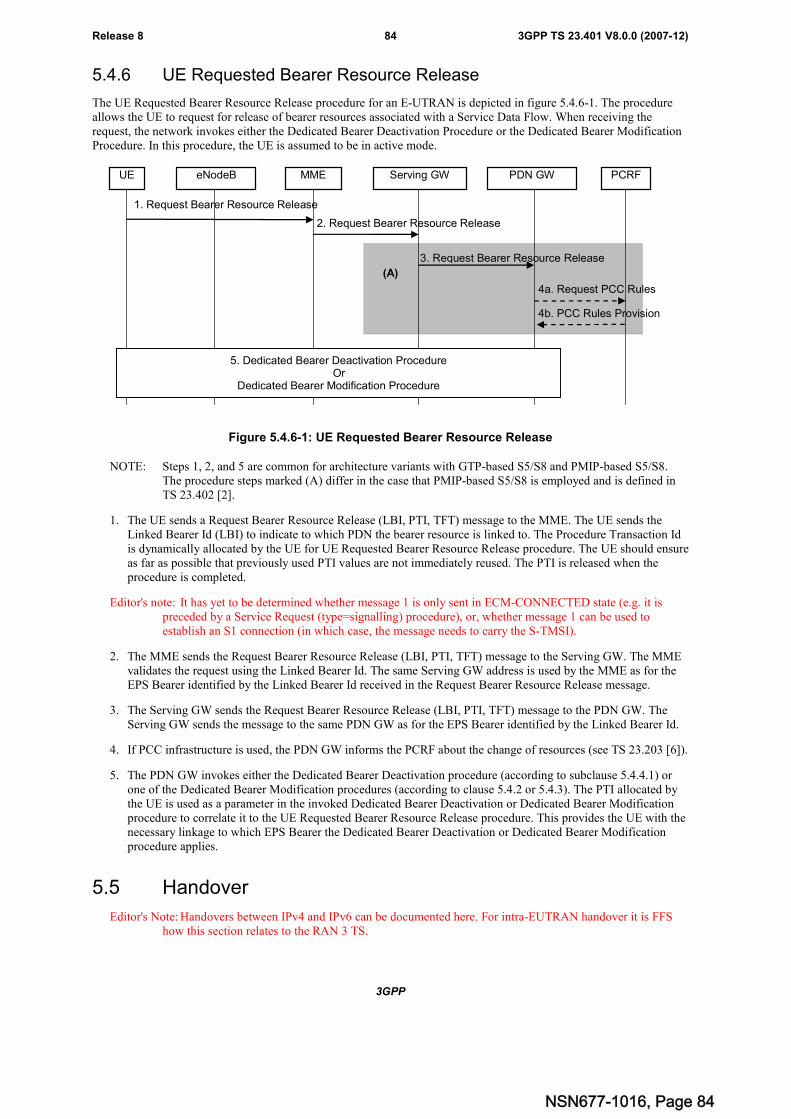
3GPP
3GPP TS 23.401 V8.0.0 (2007-12)84Release 8
5.4.6 UE Requested Bearer Resource Release
The UE Requested Bearer Resource Release procedure for an E-UTRAN is depicted in figure 5.4.6-1. The procedureallows the UE to request for release of bearer resources associated with a Service Data Flow. When receiving therequest, the network invokes either the Dedicated Bearer Deactivation Procedure or the Dedicated Bearer ModificationProcedure. In this procedure, the UE is assumed to be in active mode.
MME Serving GW PDN GW PCRF
1. Request Bearer Resource Release
2. Request Bearer Resource Release
eNodeBUE
3. Request Bearer Resource Release
5. Dedicated Bearer Deactivation ProcedureOr
Dedicated Bearer Modification Procedure
(A)
4b. PCC Rules Provision
4a. Request PCC Rules
Figure 5.4.6-1: UE Requested Bearer Resource Release
NOTE: Steps 1, 2, and 5 are common for architecture variants with GTP-based S5/S8 and PMIP-based S5/S8.The procedure steps marked (A) differ in the case that PMIP-based S5/S8 is employed and is defined inTS 23.402 [2].
1. The UE sends a Request Bearer Resource Release (LBI, PTI, TFT) message to the MME. The UE sends theLinked Bearer Id (LBI) to indicate to which PDN the bearer resource is linked to. The Procedure Transaction Idis dynamically allocated by the UE for UE Requested Bearer Resource Release procedure. The UE should ensureas far as possible that previously used PTI values are not immediately reused. The PTI is released when theprocedure is completed.
Editor's note: It has yet to be determined whether message 1 is only sent in ECM-CONNECTED state (e.g. it ispreceded by a Service Request (type=signalling) procedure), or, whether message 1 can be used toestablish an S1 connection (in which case, the message needs to carry the S-TMSI).
2. The MME sends the Request Bearer Resource Release (LBI, PTI, TFT) message to the Serving GW. The MMEvalidates the request using the Linked Bearer Id. The same Serving GW address is used by the MME as for theEPS Bearer identified by the Linked Bearer Id received in the Request Bearer Resource Release message.
3. The Serving GW sends the Request Bearer Resource Release (LBI, PTI, TFT) message to the PDN GW. TheServing GW sends the message to the same PDN GW as for the EPS Bearer identified by the Linked Bearer Id.
4. If PCC infrastructure is used, the PDN GW informs the PCRF about the change of resources (see TS 23.203 [6]).
5. The PDN GW invokes either the Dedicated Bearer Deactivation procedure (according to subclause 5.4.4.1) orone of the Dedicated Bearer Modification procedures (according to clause 5.4.2 or 5.4.3). The PTI allocated bythe UE is used as a parameter in the invoked Dedicated Bearer Deactivation or Dedicated Bearer Modificationprocedure to correlate it to the UE Requested Bearer Resource Release procedure. This provides the UE with thenecessary linkage to which EPS Bearer the Dedicated Bearer Deactivation or Dedicated Bearer Modificationprocedure applies.
5.5 Handover
Editor's Note: Handovers between IPv4 and IPv6 can be documented here. For intra-EUTRAN handover it is FFShow this section relates to the RAN 3 TS.
NSN677-1016, Page 84
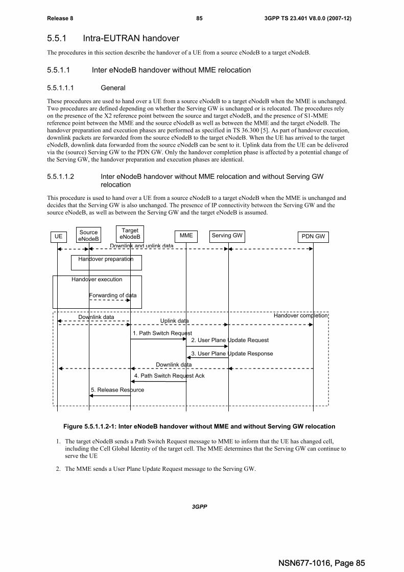
3GPP
3GPP TS 23.401 V8.0.0 (2007-12)85Release 8
5.5.1 Intra-EUTRAN handover
The procedures in this section describe the handover of a UE from a source eNodeB to a target eNodeB.
5.5.1.1 Inter eNodeB handover without MME relocation
5.5.1.1.1 General
These procedures are used to hand over a UE from a source eNodeB to a target eNodeB when the MME is unchanged.Two procedures are defined depending on whether the Serving GW is unchanged or is relocated. The procedures relyon the presence of the X2 reference point between the source and target eNodeB, and the presence of S1-MMEreference point between the MME and the source eNodeB as well as between the MME and the target eNodeB. Thehandover preparation and execution phases are performed as specified in TS 36.300 [5]. As part of handover execution,downlink packets are forwarded from the source eNodeB to the target eNodeB. When the UE has arrived to the targeteNodeB, downlink data forwarded from the source eNodeB can be sent to it. Uplink data from the UE can be deliveredvia the (source) Serving GW to the PDN GW. Only the handover completion phase is affected by a potential change ofthe Serving GW, the handover preparation and execution phases are identical.
5.5.1.1.2 Inter eNodeB handover without MME relocation and without Serving GWrelocation
This procedure is used to hand over a UE from a source eNodeB to a target eNodeB when the MME is unchanged anddecides that the Serving GW is also unchanged. The presence of IP connectivity between the Serving GW and thesource eNodeB, as well as between the Serving GW and the target eNodeB is assumed.
Handover completion
UESourceeNodeB
Serving GW PDN GWMMETarget
eNodeB
Handover execution
Downlink and uplink data
Handover preparation
Forwarding of data
Downlink dataUplink data
1. Path Switch Request2. User Plane Update Request
3. User Plane Update Response
4. Path Switch Request Ack
5. Release Resource
Downlink data
Figure 5.5.1.1.2-1: Inter eNodeB handover without MME and without Serving GW relocation
1. The target eNodeB sends a Path Switch Request message to MME to inform that the UE has changed cell,including the Cell Global Identity of the target cell. The MME determines that the Serving GW can continue toserve the UE
2. The MME sends a User Plane Update Request message to the Serving GW.
NSN677-1016, Page 85
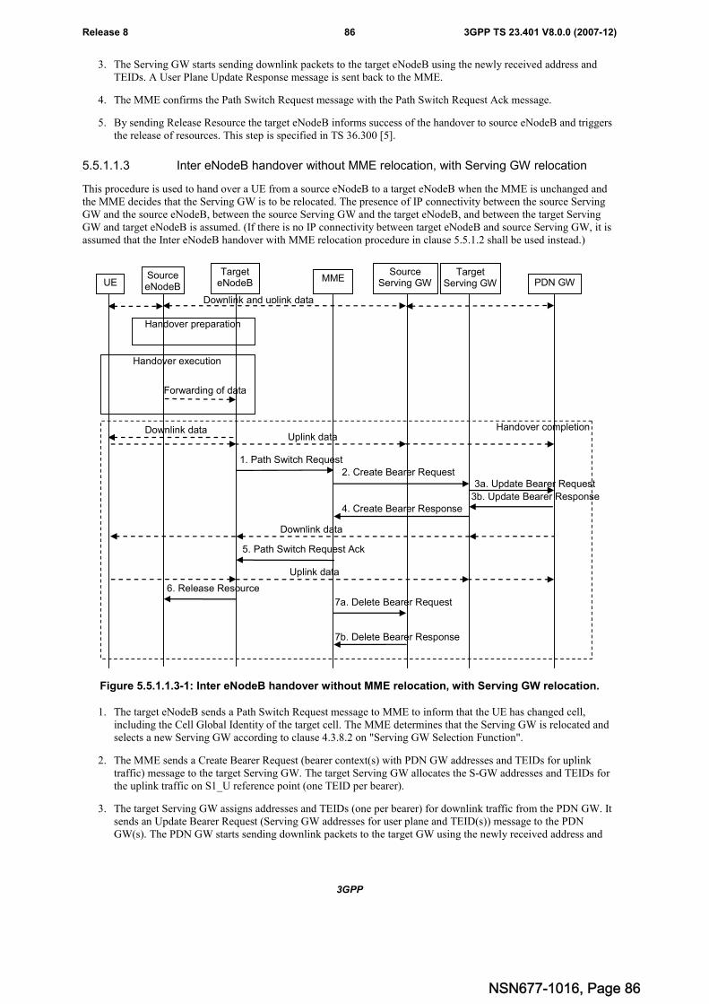
3GPP
3GPP TS 23.401 V8.0.0 (2007-12)86Release 8
3. The Serving GW starts sending downlink packets to the target eNodeB using the newly received address andTEIDs. A User Plane Update Response message is sent back to the MME.
4. The MME confirms the Path Switch Request message with the Path Switch Request Ack message.
5. By sending Release Resource the target eNodeB informs success of the handover to source eNodeB and triggersthe release of resources. This step is specified in TS 36.300 [5].
5.5.1.1.3 Inter eNodeB handover without MME relocation, with Serving GW relocation
This procedure is used to hand over a UE from a source eNodeB to a target eNodeB when the MME is unchanged andthe MME decides that the Serving GW is to be relocated. The presence of IP connectivity between the source ServingGW and the source eNodeB, between the source Serving GW and the target eNodeB, and between the target ServingGW and target eNodeB is assumed. (If there is no IP connectivity between target eNodeB and source Serving GW, it isassumed that the Inter eNodeB handover with MME relocation procedure in clause 5.5.1.2 shall be used instead.)
Handover completion
UESourceeNodeB
SourceServing GW PDN GWMME
TargetServing GW
TargeteNodeB
Handover execution
3a. Update Bearer Request
Downlink and uplink data
Handover preparation
Forwarding of data
Downlink dataUplink data
1. Path Switch Request
3b. Update Bearer Response
2. Create Bearer Request
4. Create Bearer Response
5. Path Switch Request Ack
6. Release Resource
Downlink data
Uplink data
7a. Delete Bearer Request
7b. Delete Bearer Response
Figure 5.5.1.1.3-1: Inter eNodeB handover without MME relocation, with Serving GW relocation.
1. The target eNodeB sends a Path Switch Request message to MME to inform that the UE has changed cell,including the Cell Global Identity of the target cell. The MME determines that the Serving GW is relocated andselects a new Serving GW according to clause 4.3.8.2 on "Serving GW Selection Function".
2. The MME sends a Create Bearer Request (bearer context(s) with PDN GW addresses and TEIDs for uplinktraffic) message to the target Serving GW. The target Serving GW allocates the S-GW addresses and TEIDs forthe uplink traffic on S1_U reference point (one TEID per bearer).
3. The target Serving GW assigns addresses and TEIDs (one per bearer) for downlink traffic from the PDN GW. Itsends an Update Bearer Request (Serving GW addresses for user plane and TEID(s)) message to the PDNGW(s). The PDN GW starts sending downlink packets to the target GW using the newly received address and
NSN677-1016, Page 86
3GPP
3GPP TS 23.401 V8.0.0 (2007-12)87Release 8
TEIDs. These downlink packets will use the new downlink path via the target Serving GW to the target eNodeB.An Update Bearer Response message is sent back to the target serving GW.
4. The target Serving GW sends a Create Bearer Response (Serving GW addresses and uplink TEID(s) for userplane) message back to the target MME. The MME starts a timer, to be used in step 7.
5. The MME confirms the Path Switch Request message with the Path Switch Request Ack (Serving GW addressesand uplink TEID(s) for user plane) message. The target eNodeB starts using the new Serving GW address(es)and TEID(s) for forwarding subsequent uplink packets.
6. By sending Release Resource the target eNodeB informs success of the handover to source eNodeB and triggersthe release of resources. This step is specified in TS 36.300 [5].
7. When the timer has expired after step 4, the source MME releases the bearer(s) in the source Serving GW bysending a Delete Bearer Request message, which is acknowledged by the Serving GW.
Editor's note: The case of PMIP-based S5/S8 is FFS.
5.5.1.2 Inter eNodeB handover with MME relocation
The inter eNodeB handover with MME relocation procedure is used to relocate MME, or both the MME and theServing GW. The procedure is initiated in the source eNodeB. The source MME selects the target MME. The MMEshould not be relocated during inter-eNodeB handover unless the UE leaves the MME Pool Area where the UE isserved. If The target MME determines if the Serving GW needs to be relocated. If the Serving GW needs to berelocated the target MME selects the target Serving GW, as specified in clause 4.3.8.2 on Serving GW selectionfunction.
The source eNodeB decides which of the EPS bearers are subject for forwarding of packets from the source eNodeB tothe target eNodeB. The EPC does not change the decisions taken by the RAN node. Packet forwarding can take placeeither directly from the source eNodeB to the target eNodeB, or indirectly from the source eNodeB to the targeteNodeB via the source and target Serving GWs (or if the Serving GW is not relocated, only the single Serving GW).
The availability of a direct forwarding path is determined in the source eNodeB and indicated to the source MME. If X2connectivity is available between the source and target eNodeBs, a direct forwarding path is available.
If a direct forwarding path is not available, indirect forwarding may be used. The MMEs (source and target) useconfiguration data to determine whether indirect forwarding paths are to be established. Depending on configurationdata, the source MME determines and indicates to the target MME whether indirect forwarding paths should beestablished. Based on this indication and on its configuration data, the target MME determines whether indirectforwarding paths are established.
NSN677-1016, Page 87
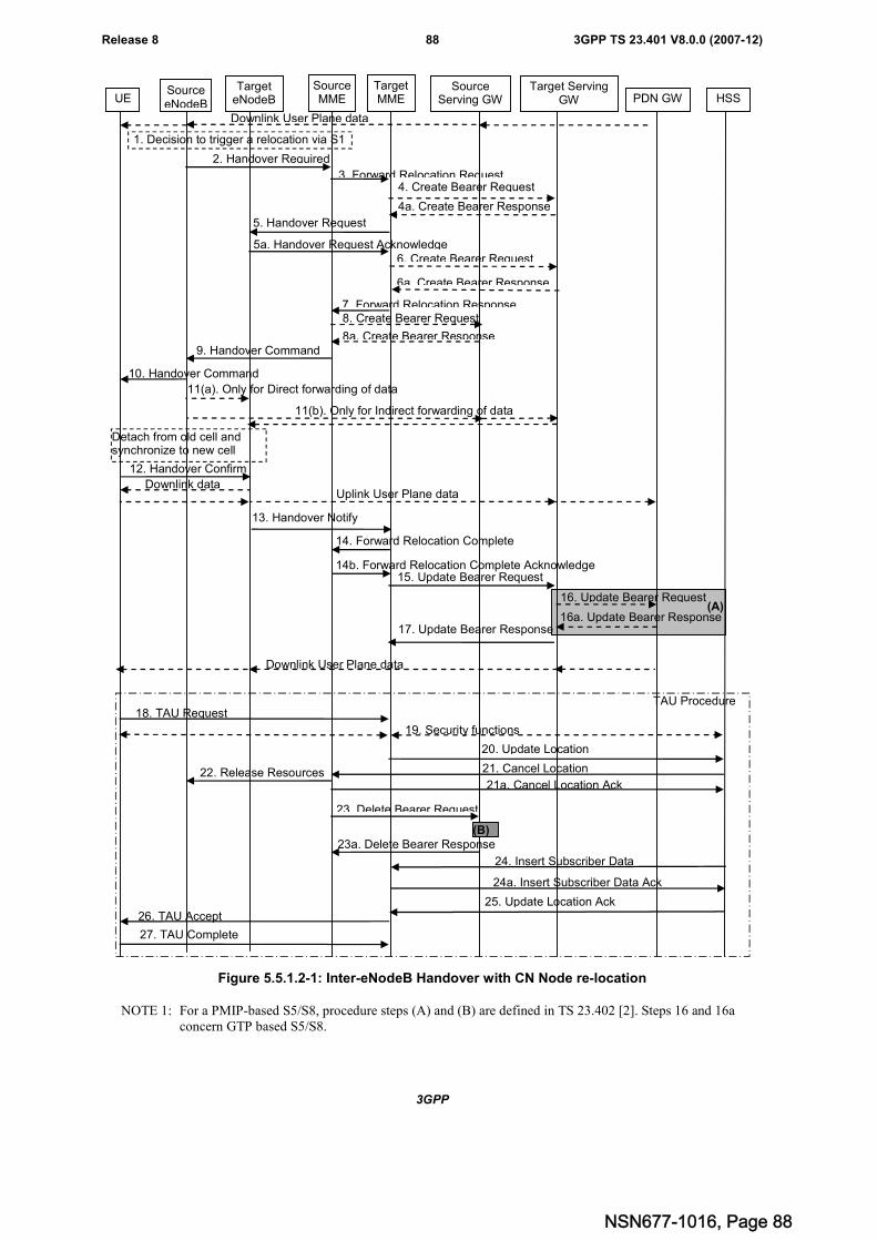
3GPP
3GPP TS 23.401 V8.0.0 (2007-12)88Release 8
UESourceeNodeB
SourceMME
SourceServing GW PDN GW
TargetMME
Target ServingGW
TargeteNodeB
Detach from old cell andsynchronize to new cell
HSS
16. Update Bearer Request
17. Update Bearer Response
15. Update Bearer Request
Downlink User Plane data
2. Handover Required
Downlink User Plane data
1. Decision to trigger a relocation via S1
3. Forward Relocation Request4. Create Bearer Request
4a. Create Bearer Response
5. Handover Request
5a. Handover Request Acknowledge
7. Forward Relocation Response
9. Handover Command
10. Handover Command
11(a). Only for Direct forwarding of data
12. Handover Confirm
Downlink dataUplink User Plane data
13. Handover Notify
14. Forward Relocation Complete
14b. Forward Relocation Complete Acknowledge
22. Release Resources
18. TAU Request
19. Security functions
20. Update Location
21. Cancel Location
21a. Cancel Location Ack
25. Update Location Ack
23. Delete Bearer Request
23a. Delete Bearer Response
27. TAU Complete
26. TAU Accept
16a. Update Bearer Response
6. Create Bearer Request
6a. Create Bearer Response
8. Create Bearer Request
8a. Create Bearer Response
(A)
24. Insert Subscriber Data
24a. Insert Subscriber Data Ack
TAU Procedure
11(b). Only for Indirect forwarding of data
(B)
Figure 5.5.1.2-1: Inter-eNodeB Handover with CN Node re-location
NOTE 1: For a PMIP-based S5/S8, procedure steps (A) and (B) are defined in TS 23.402 [2]. Steps 16 and 16aconcern GTP based S5/S8.
NSN677-1016, Page 88
3GPP
3GPP TS 23.401 V8.0.0 (2007-12)89Release 8
NOTE 2: If the Serving GW is not relocated, the box "Source Serving GW" in figure 5.5.1.2-1 is acting as thetarget Serving GW.
1. The source eNodeB decides to initiate an inter-eNodeB handover with CN node relocation to the target eNodeB.This can be triggered e.g. by no X2 connectivity to the target eNodeB, or by an error indication from the targeteNodeB after an unsuccessful X2-based handover, or by dynamic information learnt by the source eNodeB.
2. The source eNodeB sends Handover Required to the source MME. The source eNodeB indicates which bearersare subject to data forwarding. This message contains an indication whether direct forwarding is available fromthe source eNodeB to the target eNodeB. This indication from source eNodeB can be based on e.g. the presenceof X2.
3. The source MME selects the target MME as described in clause 4.3.8.3 on "MME Selection Function" and sendsa Forward Relocation Request (MME UE context that includes the PDN GW addresses and TEIDs at the PDNGW(s) for uplink traffic and Serving GW addresses and TEIDs for uplink traffic) message to the target MME.This message also includes an indication if direct forwarding is applied, or if indirect forwarding is going to beset up by the source side.
4. The target MME verifies whether the source Serving GW can continue to serve the UE. If not, it selects a newServing GW as described in clause 4.3.8.2 on "Serving GW Selection Function".
If the source Serving GW continues to serve the UE, no message is sent in this step. In this case, the targetServing GW is identical to the source Serving GW.
If a new Serving GW is selected, the target MME sends a Create Bearer Request (bearer context(s) with PDNGW addresses and TEIDs for uplink traffic) message to the target Serving GW. The target Serving GW allocatesthe S-GW addresses and TEIDs for the uplink traffic on S1_U reference point (one TEID per bearer). The targetServing GW sends a Create Bearer Response (Serving GW addresses and uplink TEID(s) for user plane)message back to the target MME.
5. The Target MME sends Handover Request (Serving GW addresses and uplink TEID(s) for user plane) messageto the target eNodeB. This message creates the UE context in the target eNodeB, including information about thebearers, and the security context. The target eNodeB sends a Handover Request Acknowledge message to thetarget MME. This includes the addresses and TEIDs allocated at the target eNodeB for downlink traffic on S1_Ureference point (one TEID per bearer). It is FFS if the TEIDs used for forwarding are different from the TEIDsused for downlink packets.
Editor's note: TEID used for forwarding and TEID used for downlink packets is FFS in RAN
6. If indirect forwarding is used, the target MME sets up forwarding parameters in the target Serving GW.
7. The target MME sends a Forward Relocation Response message to the source MME. In case of indirectforwarding is used this message includes Serving GW Address and TEIDs for indirect forwarding (source ortarget).
8. If indirect forwarding is used, the source MME updates the source Serving GW about the tunnels used forindirect forwarding. In case the Serving GW is relocated it includes the tunnel identifier to the target servingGW.
9. The source MME sends a Handover Command (target addresses and TEID(s) for data forwarding) message tothe source eNodeB.
10. The Handover Command is sent to the UE.
11. The source eNodeB should start forwarding of downlink data from the source eNodeB towards the targeteNodeB for bearers subject to data forwarding. This may be either direct (step 11a) or indirect forwarding (step11b).
12. After the UE has successfully synchronized to the target cell, it sends a Handover Confirm message to the targeteNodeB. Downlink packets forwarded from the source eNodeB can be sent to the UE. Also, uplink packets canbe sent from the UE, which are forwarded to the target Serving GW and on to the PDN GW.
13. The target eNodeB sends a Handover Notify message to the target MME.
NSN677-1016, Page 89
3GPP
3GPP TS 23.401 V8.0.0 (2007-12)90Release 8
14. The target MME sends a Forward Relocation Complete to the source MME. The source MME in response sendsa Forward Relocation Complete Acknowledge to the target MME. A timer in source MME is started to supervisewhen resources in Source eNodeB and Source Serving GW shall be released.
15. The target MME sends an Update Bearer Request (eNodeB addresses and TEIDs allocated at the target eNodeBfor downlink traffic on S1_U) message to the target Serving GW.
16. If the Serving GW is relocated, the target Serving GW assigns addresses and TEIDs (one per bearer) fordownlink traffic from the PDN GW. It sends an Update Bearer Request (Serving GW addresses for user planeand TEID(s)) message to the PDN GW(s). The PDN GW starts sending downlink packets to the target GW usingthe newly received address and TEIDs. These downlink packets will use the new downlink path via the targetServing GW to the target eNodeB. An Update Bearer Response message is sent back to the target serving GW.
If the Serving GW is not relocated, no message is sent in this step and downlink packets from the Serving-GWare immediately sent on to the target eNodeB.
It is FFS if the target eNodeB needs to take any action to avoid sending DL PDUs received from the Serving-GW to the UE before data received from the old eNodeB have been sent to the UE.
17. The target Serving GW sends an Update Bearer Response message to the target MME.
18. The UE sends a Tracking Area Update Request message to the target MME informing it that the UE is located ina new tracking area.
The target MME knows that it is a Handover procedure that has been performed for this UE and can thereforeexclude the context procedures between source MME and target MME which normally are used within the TAUpdate procedure.
19. At this point the target MME may optionally invoke security function. The security function can be deferred andperformed at any later time as well. Procedures are defined in the clause "Security Function".
20.The target MME informs the HSS of the change of CN node by sending Update Location (MME Address, IMSI)message to the HSS.
21. The HSS sends a Cancel Location (IMSI, Cancellation Type) message to the source MME with CancellationType set to Update Procedure. The source MME acknowledges with a Cancel Location Acknowledge (IMSI)message. This message allows the source MME to release the bearer(s) in the source eNodeB (step 22) and theServing GW (step 23).
22. After the timer started at step 14 expires the source MME sends a Release Resources message to the sourceeNodeB. The source eNodeB releases its resources related to the UE.
23. The source MME removes the MM context and it deletes the EPS bearer resources by sending Delete BearerRequest (Cause, TEID) messages to the Source Serving GW. If the Serving GW is not relocated, only thesignalling relationship is released between the Serving GW and the source MME, but the UE context continuesto exist in the Serving GW. The Source Serving GW acknowledges with Delete Bearer Response (TEID)messages. If resources for indirect forwarding have been allocated then they are released.
24. The HSS sends Insert Subscriber Data (IMSI, Subscription data) message to the target MME. The target MMEvalidates the UE presence in the new TA. If all checks are successful for the UE the target MME returns anInsert Subscriber Data Acknowledge (IMSI) message to the HSS.
25. The HSS acknowledges the Update Location by returning an Update Location Ack (IMSI) message to the targetMME.
26. The target MME validates the UE presence in the new TA. If the UE is allowed to be attached in this TA, thetarget MME updates the MM context and sends a Tracking Area Update Accept (GUTI, TAI-List) message tothe UE. The GUTI and TAI-list are allocated by the target MME.
27. The UE confirms the re-allocation of the new GUTI by responding to the target MME with a Tracking AreaUpdate Complete message.
NSN677-1016, Page 90
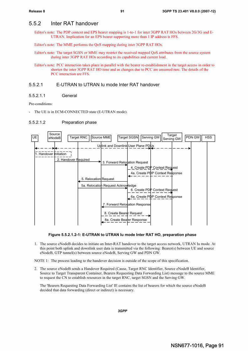
3GPP
3GPP TS 23.401 V8.0.0 (2007-12)91Release 8
5.5.2 Inter RAT handover
Editor's note: The PDP context and EPS bearer mapping is 1-to-1 for inter 3GPP RAT HOs between 2G/3G and E-UTRAN. Implication for an EPS bearer supporting more than 1 IP address is FFS.
Editor's note: The MME performs the QoS mapping during inter 3GPP RAT HOs.
Editor's note: The target SGSN or MME may restrict the received mapped QoS attributes from the source systemduring inter 3GPP RAT HOs according to its capabilities and current load.
Editor's note: PCC interaction takes place in parallel with the bearer re-establishment in the target access in order toshorten the inter 3GPP RAT HO time and as changes due to PCC are assumed rare. The details of thePCC interaction are FFS.
5.5.2.1 E-UTRAN to UTRAN Iu mode Inter RAT handover
5.5.2.1.1 General
Pre-conditions:
- The UE is in ECM-CONNECTED state (E-UTRAN mode).
5.5.2.1.2 Preparation phase
UESourceeNodeB Target RNC Source MME Target SGSN Serving GW HSS
1. Handover Initiation
2. Handover Required3. Forward Relocation Request
5. Relocation Request
5a. Relocation Request Acknowledge
8. Create Bearer Request
7. Forward Relocation Response
PDN GW
8a. Create Bearer Response
Uplink and Downlink User Plane PDUs
6. Create PDP Context Request
6a. Create PDP Context Response
TargetServing GW
4. Create PDP Context Request
4a. Create PDP Context Response
Figure 5.5.2.1.2-1: E-UTRAN to UTRAN Iu mode Inter RAT HO, preparation phase
1. The source eNodeB decides to initiate an Inter-RAT handover to the target access network, UTRAN Iu mode. Atthis point both uplink and downlink user data is transmitted via the following: Bearer(s) between UE and sourceeNodeB, GTP tunnel(s) between source eNodeB, Serving GW and PDN GW.
NOTE 1: The process leading to the handover decision is outside of the scope of this specification.
2. The source eNodeB sends a Handover Required (Cause, Target RNC Identifier, Source eNodeB Identifier,Source to Target Transparent Container, Bearers Requesting Data Forwarding List) message to the source MMEto request the CN to establish resources in the target RNC, target SGSN and the Serving GW.
The 'Bearers Requesting Data Forwarding List' IE contains the list of bearers for which the source eNodeBdecided that data forwarding (direct or indirect) is necessary.
NSN677-1016, Page 91
3GPP
3GPP TS 23.401 V8.0.0 (2007-12)92Release 8
3. The source MME maps the EPS bearers to PDP contexts 1-to-1 and maps the EPS QoS parameter values of anEPS bearer to the pre-Rel-8 QoS parameter values of a PDP context as defined in Annex E. The PDP Contextsshall be sent in a prioritized order, i.e. the most important PDP Context first. The prioritization method isimplementation dependent, but should be based on the current activity.
NOTE 2: Assigning the highest priority to the PDP context without TFT could be done to get service continuity forall ongoing services regardless of the number of supported EPS bearers in the UE and network.
The source MME determines from the 'Target RNC Identifier' IE that the type of handover is IRAT Handover toUTRAN Iu mode. The Source MME initiates the Handover resource allocation procedure by sending a ForwardRelocation Request (IMSI, Target Identification, MM Context, PDP Context, MME Tunnel Endpoint Identifierfor Control Plane, MME Address for Control plane, Source to Target Transparent Container, S1-AP CauseDirect Forwarding Flag) message to the target SGSN. This message includes all PDP contexts corresponding tothe bearers established in the source system and the uplink Tunnel endpoint parameters of the Serving GW.
'Direct Forwarding Flag' IE indicates if Direct Forwarding of data to Target side shall be used or not. This flag isset by the source MME.
The MM context contains security related information, e.g. supported ciphering algorithms as described inTS 29.060 [14]. The relation between UTRAN and EPS security parameters is FFS.
Editor's note: This needs to be aligned with security requirements for Release 8.
Editor's note: It is FFS how the mapping of individual parameters and bearer identifiers is done. It is FFS how thebearer identifiers are mapped.
4. The target SGSN determines if the Serving GW is relocated, e.g., due to PLMN change. If the Serving GW isrelocated, the target SGSN selects the target Serving GW as described under clause 4.3.8.2 on "Serving GWselection function", and sends a Create PDP Context Request message (IMSI, SGSN Tunnel Endpoint Identifierfor Control Plane, SGSN Address for Control plane, PDN GW address(es) for user plane, PDN GW UL TEID(s)for user plane, PDN GW address(es) for control plane, and PDN GW TEID(s) for control plane) to the targetServing GW.
The target SGSN establishes the PDP context(s) in the indicated order. The SGSN deactivates the PDP contextswhich cannot be established.
4a. The target Serving GW allocates its local resources and returns a Create PDP Context Response (Serving GWaddress(es) for user plane, Serving GW UL TEID(s) for user plane, Serving GW DL TEID(s), Serving GWAddress for control plane, Serving GW TEID for control plane) message to the target SGSN.
5. The target SGSN requests the target RNC to establish the radio network resources (RABs) by sending themessage Relocation Request (UE Identifier, Cause, CN Domain Indicator, Integrity protection information (i.e.IK and allowed Integrity Protection algorithms), Encryption information (i.e. CK and allowed Cipheringalgorithms), RAB to be setup list, Source to Target Transparent Container).
For each RAB requested to be established, RABs To Be Setup shall contain information such as RAB ID, RABparameters, Transport Layer Address, and Iu Transport Association. The target SGSN shall not request resourcesfor which the Activity Status Indicator within a PDP Context indicates that no active radio bearer exist on thesource side for that PDP Context. The RAB ID information element contains the NSAPI value, and the RABparameters information element gives the QoS profile. The Transport Layer Address is the Serving GW Addressfor user data, and the Iu Transport Association corresponds to the uplink Tunnel Endpoint Identifier Data.
Ciphering and integrity protection keys are sent to the target RNC to allow data transfer to continue in the newRAT/mode target cell without requiring a new AKA (Authentication and Key Agreement) procedure.Information that is required to be sent to the UE (either in the Relocation Command message or after thehandover completion message) from RRC in the target RNC shall be included in the RRC message sent from thetarget RNC to the UE via the transparent container.
In the target RNC radio and Iu user plane resources are reserved for the accepted RABs.
5a. The target RNC allocates the resources and returns the applicable parameters to the target SGSN in the messageRelocation Request Acknowledge(Target to Source Transparent Container, RABs setup list, RABs failed tosetup list).
NSN677-1016, Page 92
3GPP
3GPP TS 23.401 V8.0.0 (2007-12)93Release 8
Upon sending the Relocation Request Acknowledge message the target RNC shall be prepared to receivedownlink GTP PDUs from the Serving GW for the accepted RABs.
Each RAB to be setup is defined by a Transport Layer Address, which is the target RNC Address for user data,and the Iu Transport Association, which corresponds to the downlink Tunnel Endpoint Identifier for user data.
6. If indirect forwarding applies the target SGSN sends a Create PDP Context Request message (IMSI SGSNTunnel Endpoint Identifier for Control Plane, SGSN Address for Control plane, Target RNC Address andTEID(s) for DL user plane) to the target Serving GW.
6a. The target Serving GW returns a Create PDP Context Response (Cause) message to the target SGSN.
7. The target SGSN sends the message Forward Relocation Response (Cause, SGSN Tunnel Endpoint Identifier forControl Plane, SGSN Address for Control Plane, Target to Source Transparent Container, RANAP cause, RABSetup Information, Additional RAB Setup Information, Address(es) and TEID(s) for User Traffic DataForwarding) to the source MME.
If 'Direct Forwarding' is applicable, then the IE 'Address(es) and TEID(s) for User Traffic Data Forwarding'contains the GTP-U tunnel endpoint parameters to the Target RNC. Otherwise the IE 'Address(es) and TEID(s)for User Traffic Data Forwarding' may contain the GTP-U tunnel endpoint parameters to the Serving GW (or tothe Target Serving GW for Serving GW re-location).
8. If the "Direct Forwarding" is not applicable, the Source MME sends the message Create Bearer Request (Cause,Address(es) and TEID(s) for Data Forwarding (see step 7), NSAPI(s)) to the Serving GW used for indirectpacket forwarding. The Cause indicates that the bearer(s) are subject to data forwarding.
Indirect forwarding may be performed via a Serving GW which is different from the Serving GW used as theanchor point for the UE.
8a. The Serving GW returns the forwarding parameters by sending the message Create Bearer Response (Cause,Serving GW Address(es) and TEID(s) for Data Forwarding). If the Serving GW doesn't support data forwarding,an appropriate cause value shall be returned and the Serving GW Address(es) and TEID(s) will not be includedin the message.
NSN677-1016, Page 93
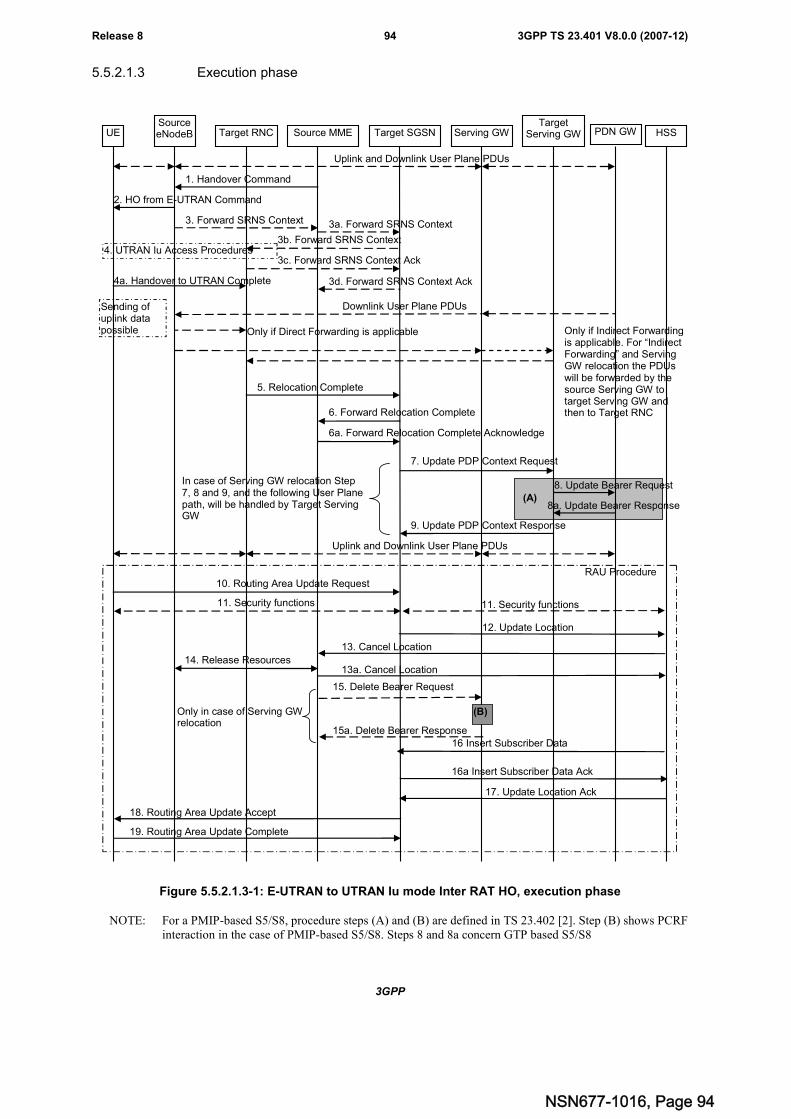
3GPP
3GPP TS 23.401 V8.0.0 (2007-12)94Release 8
5.5.2.1.3 Execution phase
UESourceeNodeB Target RNC Source MME Target SGSN Serving GW HSSPDN GW
Uplink and Downlink User Plane PDUs
1. Handover Command
2. HO from E-UTRAN Command
Sending ofuplink datapossible
4. UTRAN Iu Access Procedures
3a. Forward SRNS Context
3b. Forward SRNS Context
3c. Forward SRNS Context Ack
3d. Forward SRNS Context Ack
5. Relocation Complete
6. Forward Relocation Complete
6a. Forward Relocation Complete Acknowledge
7. Update PDP Context Request
8a. Update Bearer Response
9. Update PDP Context Response
Uplink and Downlink User Plane PDUs
3. Forward SRNS Context
10. Routing Area Update RequestRAU Procedure
4a. Handover to UTRAN Complete
Downlink User Plane PDUs
Only if Direct Forwarding is applicable Only if Indirect Forwardingis applicable. For “IndirectForwarding” and ServingGW relocation the PDUswill be forwarded by thesource Serving GW totarget Serving GW andthen to Target RNC
14. Release Resources
11. Security functions
18. Routing Area Update Accept
11. Security functions
12. Update Location
13. Cancel Location
13a. Cancel LocationAck
17. Update Location Ack
19. Routing Area Update Complete
TargetServing GW
In case of Serving GW relocation Step7, 8 and 9, and the following User Planepath, will be handled by Target ServingGW
(A)
16 Insert Subscriber Data
16a Insert Subscriber Data Ack
15. Delete Bearer Request
15a. Delete Bearer Response
Only in case of Serving GWrelocation
(B)
8. Update Bearer Request
Figure 5.5.2.1.3-1: E-UTRAN to UTRAN Iu mode Inter RAT HO, execution phase
NOTE: For a PMIP-based S5/S8, procedure steps (A) and (B) are defined in TS 23.402 [2]. Step (B) shows PCRFinteraction in the case of PMIP-based S5/S8. Steps 8 and 8a concern GTP based S5/S8
NSN677-1016, Page 94
3GPP
3GPP TS 23.401 V8.0.0 (2007-12)95Release 8
Editor's note: It's FFS how the interaction with HSS is affected by the Idle-mode Signalling Reduction (ISR)function.
The source eNodeB continues to receive downlink and uplink user plane PDUs.
1. The source MME completes the preparation phase towards source eNodeB by sending the message HandoverCommand (Target to Source Transparent Container, Bearers Subject to Data Forwarding List). The "BearersSubject to Data forwarding list" IE may be included in the message and it shall be a list of 'Address(es) andTEID(s) for user traffic data forwarding' received from target side in the preparation phase (Forward RelocationResponse message).
The source eNodeB initiates data forwarding for bearers specified in the "Bearers Subject to Data ForwardingList". The data forwarding may go directly to target RNC or alternatively go via the Serving GW if so decidedby source MME and or/ target SGSN in the preparation phase.
2. The source eNodeB will give a command to the UE to handover to the target access network via the message HOfrom E-UTRAN Command. This message includes a transparent container including radio aspect parameters thatthe target RNC has set-up in the preparation phase. The details of this E-UTRAN specific signalling aredescribed in TS 36.300 [5].
Upon the reception of the HO from E-UTRAN Command message containing the Handover Command message,the UE shall associate its bearer IDs to the respective RABs based on the relation with the NSAPI and shallsuspend the uplink transmission of the user plane data.
3. The source eNodeB informs the source MME which then informs the target SGSN regarding "delivery order"parameters in the message Forward SRNS Context. The Target SGSN forwards the SRNS Context to the TargetRNC.
Editor's Note: The need for step 3 is FFS.
4. The UE moves to the target UTRAN Iu (3G) system and executes the handover according to the parametersprovided in the message delivered in step 2. The procedure is the same as in step 6 and 8 in subclause 5.2.2.2 inTS 43.129 [8] with the additional function of association of the received RABs and existing Bearer Id related tothe particular NSAPI. Relation between NSAPI, RAB and Bearer Id is FFS.
The UE may resume the user data transfer only for those NSAPIs for which there are radio resources allocated inthe target RNC.
5. When the new source RNC-ID + S-RNTI are successfully exchanged with the UE, the target RNC shall send theRelocation Complete message to the target SGSN. The purpose of the Relocation Complete procedure is toindicate by the target RNC the completion of the relocation from the source E-UTRAN to the RNC. After thereception of the Relocation Complete message the target SGSN shall be prepared to receive data from the targetRNC. Each uplink N-PDU received by the target SGSN is forwarded directly to the Serving GW.
6. Then the target SGSN knows that the UE has arrived to the target side and target SGSN informs the sourceMME by sending the message Forward Relocation Complete. The source MME will also acknowledge thatinformation. A timer in source MME is started to supervise when resources in Source eNodeB and SourceServing GW (for Serving GW relocation) shall be released (normally this will occur when Source MME receivesthe message Cancel Location from HSS). Further action in the source MME continues at step 13.
7. The target SGSN will now complete the Handover procedure by informing the Serving GW (for Serving GWrelocation this will be the Target Serving GW) that the target SGSN is now responsible for all the PDP Contextthe UE have established. This is performed in the message Update PDP Context Request (SGSN TunnelEndpoint Identifier for Control Plane, NSAPI(s), SGSN Address for Control Plane, SGSN Address(es) andTEID(s) or RNC Address(es) and TEID(s) for User Traffic, and RAT type).
8. The Serving GW (for Serving GW relocation this will be the Target Serving GW) may inform the PDN GW(s)the change of for example for Serving GW relocation or the RAT type that e.g. can be used for charging, bysending the message Update Bearer Request. The PDN GW must acknowledge the request with the messageUpdate Bearer Response.
If PCC infrastructure is used, the PDN GW informs the PCRF about the change of, for example, the RAT type.
9. The Serving GW (for Serving GW relocation this will be the Target Serving GW) acknowledges the user planeswitch to the target SGSN via the message Update PDP Context Response (Cause, Serving GW Tunnel Endpoint
NSN677-1016, Page 95
3GPP
3GPP TS 23.401 V8.0.0 (2007-12)96Release 8
Identifier for Control Plane, Serving GW Address for Control Plane, Protocol Configuration Options). At thisstage the user plane path is established for all PDP contexts between the UE, target RNC, Serving GW (forServing GW relocation this will be the Target Serving GW) and PDN GW.
10. The UE sends a Routeing Area Update Request message to the target SGSN informing it that the UE is locatedin a new routing area. The UE shall send this message immediate after step 4a.
The target SGSN knows that an IRAT Handover has been performed for this UE and can therefore exclude thecontext procedures between source MME and target SGSN which normally are used within the RA Updateprocedure.
11. At this point the target SGSN may optionally invoke security function. The security function can be deferred andperformed at any later time as well. Procedures are defined in the clause "Security Function".
12. The target SGSN informs the HSS of the change of CN node by sending Update Location (SGSN Number,SGSN Address, IMSI) message to the HSS.
13. The HSS sends a Cancel Location (IMSI, Cancellation Type) message to the source MME with CancellationType set to Update Procedure. The source MME acknowledges with a Cancel Location Acknowledge (IMSI)message.
14. After the source MME has received the Cancel Location message or the timer started at Step 6 expires, thesource MME sends a Release Resources message to the Source eNodeB. The Source eNodeB releases itsresources related to the UE.
15. This step is only performed in case of Serving GW relocation. When the source MME removes the MM context,the source MME deletes the EPS bearer resources by sending Delete Bearer Request (Cause, TEID) messages tothe Source Serving GW. The source MME shall indicate to the Source Serving GW that the Source Serving GWshall not initiate a delete procedure towards the PDN GW. The Source Serving GW acknowledges with DeleteBearer Response (TEID) messages.
16. The HSS sends Insert Subscriber Data (IMSI, Subscription data) message to the target SGSN. The target SGSNvalidates the UE presence in the new RA. If all checks are successful for the UE the target SGSN returns anInsert Subscriber Data Acknowledge (IMSI) message to the HSS.
17. The HSS acknowledges the Update Location by returning an Update Location Ack (IMSI) message to the targetSGSN.
18. The target SGSN validates the UE presence in the new RA. If the UE is allowed to be attached in this RA, thetarget SGSN updates the MM context and sends a Routing Area Update Accept (P-TMSI, TMSI, P-TMSIsignature, etc.) message to the UE.
Editor's note: The mechanism by which the UE/network causes the MSC/VLR TMSI to be allocated is FFS.
19. The UE confirms the re-allocation of the new P-TMSI by responding to the target SGSN with a Routing AreaUpdate Complete message.
5.5.2.2 UTRAN Iu mode to E-UTRAN Inter RAT handover
5.5.2.2.1 General
The UTRAN Iu mode to E-UTRAN Inter RAT handover procedure takes place when the network decides to perform ahandover. The decision to perform PS handover from UTRAN Iu mode to E-UTRAN is taken by the network based onradio condition measurements reported by the UE to the UTRAN RNC.
NSN677-1016, Page 96
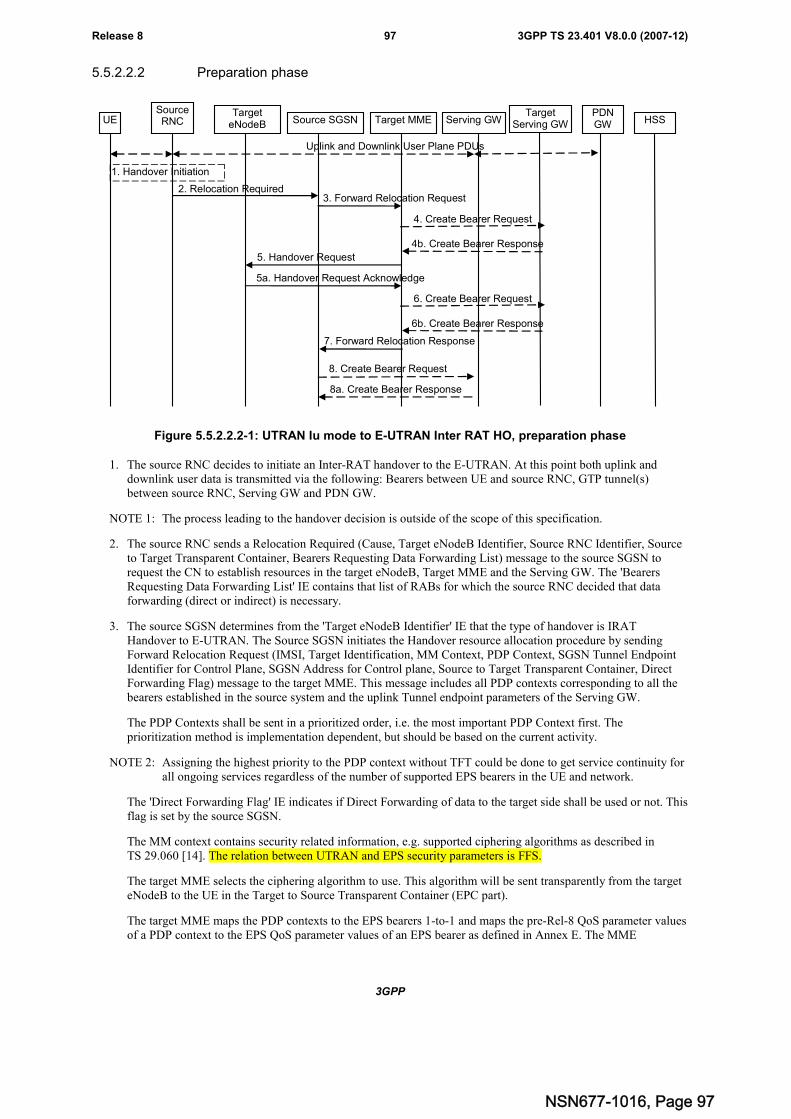
3GPP
3GPP TS 23.401 V8.0.0 (2007-12)97Release 8
5.5.2.2.2 Preparation phase
UESourceRNC
TargeteNodeB Source SGSN Target MME Serving GW HSS
1. Handover Initiation
2. Relocation Required3. Forward Relocation Request
5. Handover Request
5a. Handover Request Acknowledge
8. Create Bearer Request
7. Forward Relocation Response
PDNGW
8a. Create Bearer Response
Uplink and Downlink User Plane PDUs
6. Create Bearer Request
6b. Create Bearer Response
TargetServing GW
4. Create Bearer Request
4b. Create Bearer Response
Figure 5.5.2.2.2-1: UTRAN Iu mode to E-UTRAN Inter RAT HO, preparation phase
1. The source RNC decides to initiate an Inter-RAT handover to the E-UTRAN. At this point both uplink anddownlink user data is transmitted via the following: Bearers between UE and source RNC, GTP tunnel(s)between source RNC, Serving GW and PDN GW.
NOTE 1: The process leading to the handover decision is outside of the scope of this specification.
2. The source RNC sends a Relocation Required (Cause, Target eNodeB Identifier, Source RNC Identifier, Sourceto Target Transparent Container, Bearers Requesting Data Forwarding List) message to the source SGSN torequest the CN to establish resources in the target eNodeB, Target MME and the Serving GW. The 'BearersRequesting Data Forwarding List' IE contains that list of RABs for which the source RNC decided that dataforwarding (direct or indirect) is necessary.
3. The source SGSN determines from the 'Target eNodeB Identifier' IE that the type of handover is IRATHandover to E-UTRAN. The Source SGSN initiates the Handover resource allocation procedure by sendingForward Relocation Request (IMSI, Target Identification, MM Context, PDP Context, SGSN Tunnel EndpointIdentifier for Control Plane, SGSN Address for Control plane, Source to Target Transparent Container, DirectForwarding Flag) message to the target MME. This message includes all PDP contexts corresponding to all thebearers established in the source system and the uplink Tunnel endpoint parameters of the Serving GW.
The PDP Contexts shall be sent in a prioritized order, i.e. the most important PDP Context first. Theprioritization method is implementation dependent, but should be based on the current activity.
NOTE 2: Assigning the highest priority to the PDP context without TFT could be done to get service continuity forall ongoing services regardless of the number of supported EPS bearers in the UE and network.
The 'Direct Forwarding Flag' IE indicates if Direct Forwarding of data to the target side shall be used or not. Thisflag is set by the source SGSN.
The MM context contains security related information, e.g. supported ciphering algorithms as described inTS 29.060 [14]. The relation between UTRAN and EPS security parameters is FFS.
The target MME selects the ciphering algorithm to use. This algorithm will be sent transparently from the targeteNodeB to the UE in the Target to Source Transparent Container (EPC part).
The target MME maps the PDP contexts to the EPS bearers 1-to-1 and maps the pre-Rel-8 QoS parameter valuesof a PDP context to the EPS QoS parameter values of an EPS bearer as defined in Annex E. The MME
NSN677-1016, Page 97
3GPP
3GPP TS 23.401 V8.0.0 (2007-12)98Release 8
establishes the EPS bearer(s) in the indicated order. The MME deactivates the EPS bearers which cannot beestablished.
Editor's note: This needs to be aligned with security requirements for Release 8.
Editor's note: It is FFS how the mapping of individual parameters and bearer identifiers is done. It is FFS how thebearer identifiers are mapped.
4. The target MME determines if the Serving GW is relocated, e.g., due to PLMN change. If the Serving GW isrelocated, the target MME selects the target Serving GW as described under clause 4.3.8.2 on "Serving GWselection function". The target MME sends a Create Bearer Request message (IMSI, MME context ID, MMETunnel Endpoint Identifier for Control Plane, MME Address for Control plane, PDN GW address(es) for userplane, PDN GW UL TEID(s) for user plane, PDN GW address for control plane, and PDN GW TEID(s) forcontrol plane) to the target Serving GW.
4a. The target Serving GW allocates its local resources and returns them in a Create Bearer Response (Serving GWaddress(es) for user plane, Serving GW UL TEID(s) for user plane, Serving GW DL TEID(s) in case of indirectforwarding is supported, Serving GWAddress for control plane, Serving GW TEID for control plane) message tothe target MME.
5. The target MME will request the target eNodeB to establish the bearer(s) by sending the message HandoverRequest (UE Identifier, Cause, CN Domain Indicator, Integrity protection information (i.e. IK and allowedIntegrity Protection algorithms), Encryption information (i.e. CK and allowed Ciphering algorithms), EPSBearers to be setup list, Source to Target Transparent Container).
For each EPS bearer requested to be established, 'EPS Bearers To Be Setup' IE shall contain information such asID, bearer parameters, Transport Layer Address, and S1 Transport Association. The target MME shall notrequest resources for which the Activity Status Indicator within a PDP Context indicates that no active radiobearer exist on the source side for that PDP context. The Transport Layer Address is the Serving GW Addressfor user data, and the S1 Transport Association corresponds to the uplink Tunnel Endpoint Identifier Data.
The ciphering and integrity protection keys will be sent transparently from the target eNodeB to the UE in theTarget to Source Transparent Container, and in the message HO from UTRAN Command from source RNC tothe UE. This will then allow data transfer to continue in the new RAT/mode target cell without requiring a newAKA (Authentication and Key Agreement) procedure.
5a. The target eNodeB allocates the request resources and returns the applicable parameters to the target MME in themessage Handover Request Acknowledge (Target to Source Transparent Container, EPS Bearers setup list, EPSBearers failed to setup list). Upon sending the Handover Request Acknowledge message the target eNodeB shallbe prepared to receive downlink GTP PDUs from the Serving GW for the accepted EPS bearers.6. If indirect forwarding applies the target MME sends an Create Bearer Request message (IMSI, MME TEIDfor control plane, MME Address for control plane,, Target eNodeB Address, TEID(s) for DL user plane) to thetarget Serving GW.
6a. The target Serving GW returns a Create Bearer Response (Cause) message to the target MME.
7. The target MME sends the message Forward Relocation Response (Cause, List of Set Up RABs, MME TunnelEndpoint Identifier for Control Plane, S1-AP cause, MME Address for control plane, Target to SourceTransparent Container, Address(es) and TEID(s) for Data Forwarding) to the source SGSN.
If 'Direct Forwarding' is applicable, then the IEs 'Address(es) and TEID(s) for Data Forwarding' contains theGTP-U tunnel endpoint parameters to the eNodeB. Otherwise the IEs 'Address(es) and TEID(s) for DataForwarding' may contain the GTP-U tunnel endpoint parameters to the Serving GW (or to the Target ServingGW for Serving GW re-location).
8. If "Direct Forwarding" is not applicable, the source SGSN shall send the message Create Bearer Request (Cause,Address(es) and TEID(s) for Data Forwarding (see step 7), NSAPI(s)) to the Serving GW used for indirectpacket forwarding. The Cause shall indicate that the Bearer is subject to data forwarding.
Indirect forwarding may be performed via a Serving GW which is different from the Serving GW used as theanchor point for the UE.
8a. The Serving GW returns the forwarding user plane parameters by sending the message Create Bearer Response(Cause, Serving GW Address(es) and TEID(s) for Data Forwarding). If the Serving GW doesn't support data
NSN677-1016, Page 98
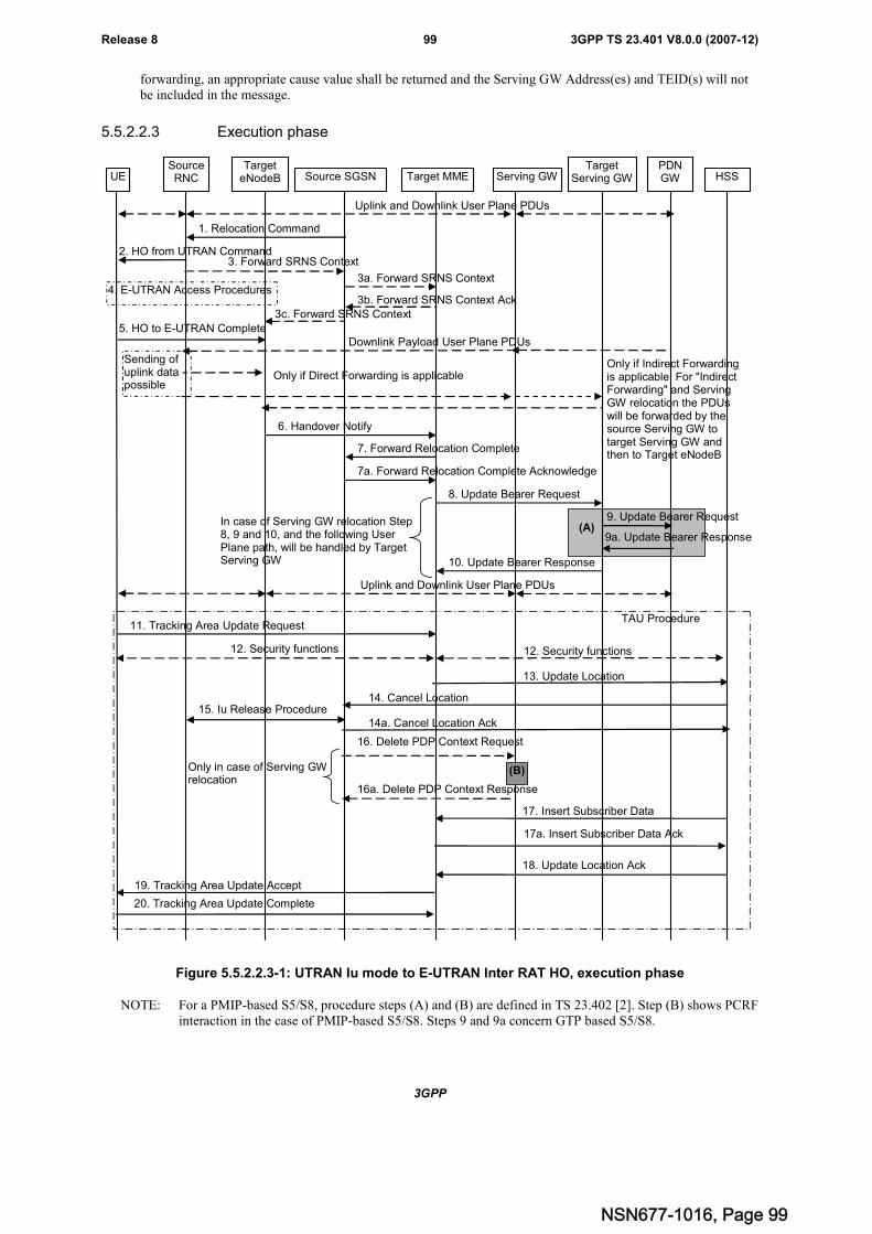
3GPP
3GPP TS 23.401 V8.0.0 (2007-12)99Release 8
forwarding, an appropriate cause value shall be returned and the Serving GW Address(es) and TEID(s) will notbe included in the message.
5.5.2.2.3 Execution phase
UESourceRNC
TargeteNodeB Source SGSN Target MME Serving GW HSS
PDNGW
Uplink and Downlink User Plane PDUs
1. Relocation Command
2. HO from UTRAN Command
Sending ofuplink datapossible
4. E-UTRAN Access Procedures3a. Forward SRNS Context
3b. Forward SRNS Context Ack
5. HO to E-UTRAN Complete
6. Handover Notify
7. Forward Relocation Complete
7a. Forward Relocation Complete Acknowledge
15. Iu Release Procedure
11. Tracking Area Update Request
8. Update Bearer Request
9a. Update Bearer Response
10. Update Bearer Response
Uplink and Downlink User Plane PDUs
TAU Procedure
Downlink Payload User Plane PDUs
Only if Direct Forwarding is applicableOnly if Indirect Forwardingis applicable. For "IndirectForwarding" and ServingGW relocation the PDUswill be forwarded by thesource Serving GW totarget Serving GW andthen to Target eNodeB
12. Security functions
19. Tracking Area Update Accept
12. Security functions
13. Update Location
14. Cancel Location
14a. Cancel Location Ack
18. Update Location Ack
20. Tracking Area Update Complete
TargetServing GW
In case of Serving GW relocation Step8, 9 and 10, and the following UserPlane path, will be handled by TargetServing GW
3. Forward SRNS Context
3c. Forward SRNS Context
(A)
17. Insert Subscriber Data
17a. Insert Subscriber Data Ack
16. Delete PDP Context Request
16a. Delete PDP Context Response
Only in case of Serving GWrelocation
(B)
9. Update Bearer Request
Figure 5.5.2.2.3-1: UTRAN Iu mode to E-UTRAN Inter RAT HO, execution phase
NOTE: For a PMIP-based S5/S8, procedure steps (A) and (B) are defined in TS 23.402 [2]. Step (B) shows PCRFinteraction in the case of PMIP-based S5/S8. Steps 9 and 9a concern GTP based S5/S8.
NSN677-1016, Page 99
3GPP
3GPP TS 23.401 V8.0.0 (2007-12)100Release 8
Editor's note: It's FFS how the interaction with HSS is affected by the Idle-mode Signalling Reduction (ISR)function.
The source RNC continues to receive downlink and uplink user plane PDUs.
1. The source SGSN completes the preparation phase towards source RNC by sending the message RelocationCommand (Target to Source Transparent Container, RABs to be Released List, RABs Subject to DataForwarding List). The "RABs to be Released list" IE will be the list of all NSAPIs (RAB Ids) for which a Bearerwas not established in Target eNodeB. The "RABs Subject to Data forwarding list" IE may be included in themessage and it shall be a list of 'Address(es) and TEID(s) for user traffic data forwarding' received from targetside in the preparation phase (Forward Relocation Response message).
2. The source RNC will command to the UE to handover to the target eNodeB via the message HO from UTRANCommand. The access network specific message to UE includes a transparent container including radio aspectparameters that the target eNodeB has set-up in the preparation phase. The procedures for this are FFS.
The source RNC may initiate data forwarding for the indicated RABs/PDP contexts specified in the "RABsSubject to Data Forwarding List". The data forwarding may go directly to target eNodeB, or alternatively go e.g.via the Serving GW if so decided by source SGSN and/or target MME in the preparation phase.
Upon the reception of the HO from UTRAN Command message containing the Relocation Command message,the UE shall associate its RAB IDs to the respective bearers ID based on the relation with the NSAPI and shallsuspend the uplink transmission of the user plane data.
3. The Source RNC may inform the Source SGSN which then informs the Target MME regarding "delivery order"parameters in the message Forward SRNS Context.
The target MME forwards the SRNS Context to eNodeB.
The need for the step 3 is FFS.
4. The UE moves to the E-UTRAN and performs access procedures toward target eNodeB.
5. When the UE has got access to target eNodeB it sends the message HO to E-UTRAN Complete.
6. When the UE has successfully accessed the target eNodeB, the target eNodeB informs the target MME bysending the message Handover Notify.
7. Then the target MME knows that the UE has arrived to the target side and target MME informs the source SGSNby sending the message Forward Relocation Complete. The source SGSN will also acknowledge thatinformation. A timer in source SGSN is started to supervise when resources in the in Source RNC and SourceServing GW (in case of Serving GW relocation) shall be released (normally this will occur when Source SGSNreceives the message Cancel Location from HSS). Further action in the source SGSN continues at step 14.
8. The target MME will now complete the Inter-RAT Handover procedure by informing the Serving GW (forServing GW relocation this will be the Target Serving GW) that the target MME is now responsible for all thebearers the UE have established. This is performed in the message Update Bearer Request (Cause, MME TunnelEndpoint Identifier for Control Plane, NSAPI, MME Address for Control Plane, eNodeB Address(es) andTEID(s) for User Traffic, and RAT type).
9. The Serving GW (for Serving GW relocation this will be the Target Serving GW) may inform the PDN GW thechange of for example for Serving GW relocation or the RAT type that e.g. can be used for charging, by sendingthe message Update Bearer Request. The PDN GW must acknowledge the request with the message UpdateBearer Response.
If PCC infrastructure is used, the PDN GW informs the PCRF about the change of, for example, the RAT type.
10. The Serving GW (for Serving GW relocation this will be the Target Serving GW) acknowledges the user planeswitch to the target MME via the message Update Bearer Response (Cause, Serving GW Tunnel EndpointIdentifier for Control Plane, Serving GW Address for Control Plane, Protocol Configuration Options). At thisstage the user plane path is established for all bearers between the UE, target eNodeB, Serving GW (for ServingGW relocation this will be the Target Serving GW) and PDN GW.
11. The UE sends a Tracking Area Update Request message to the target MME informing it that the UE is located ina new tracking area. The UE shall send this message immediately after step 5.
NSN677-1016, Page 100
3GPP
3GPP TS 23.401 V8.0.0 (2007-12)101Release 8
The target MME knows that an IRAT Handover has been performed for this UE and can therefore exclude thecontext procedures between source SGSN and target MME which normally are used within the TA Updateprocedure.
12. At this point the target MME may optionally invoke security function. The security function can be deferred andperformed at any later time as well. Procedures are defined in the clause "Security Function".
13. The target MME informs the HSS of the change of CN node by sending Update Location (MME Address, IMSI)message to the HSS.
14. The HSS sends a Cancel Location (IMSI, Cancellation Type) message to the source SGSN with CancellationType set to Update Procedure. The source SGSN acknowledges with a Cancel Location Acknowledge (IMSI)message.
15. After step 7 the source SGSN will clean-up all its resources towards source RNC by performing the Iu Releaseprocedures. When there is no longer any need for the RNC to forward data, the source RNC responds with an IuRelease Complete message.
16. This step is only performed in case of Serving GW relocation. When the source SGSN removes the MM context,the source SGSN deletes the EPS bearer resources by sending Delete PDP Context Request (Cause, TEID)messages to the Source Serving GW. The source SGSN shall indicate to the Source Serving GW that the SourceServing GW shall not initiate a delete procedure towards the PDN GW. The Source Serving GW acknowledgeswith Delete PDP Context Response (TEID) messages.
17. The HSS sends Insert Subscriber Data (IMSI, Subscription data) message to the target MME. The target MMEvalidates the UE presence in the new TA. If all checks are successful for the UE the target MME returns anInsert Subscriber Data Acknowledge (IMSI) message to the HSS.
18. The HSS acknowledges the Update Location by returning an Update Location Ack (IMSI) message to the targetMME.
19. The target MME validates the UE presence in the new TA. If the UE is allowed to be attached in this TA, thetarget MME updates the MM context and sends a Tracking Area Update Accept (S-TMSI, TAI-List, etc.)message to the UE.
20. The UE confirms the re-allocation of the new S-TMSI by responding to the target MME with a Tracking AreaUpdate Complete message.
5.5.2.3 E-UTRAN to GERAN A/Gb mode Inter RAT handover
5.5.2.3.1 General
The procedure is based on Packet-switched handover for GERAN A/Gb mode defined in TS 43.129 [8].
Pre-conditions:
- The UE is in ECM-CONNECTED state (E-UTRAN mode);
- The BSS must support PFM, Packet Flow Management, procedures.
NSN677-1016, Page 101
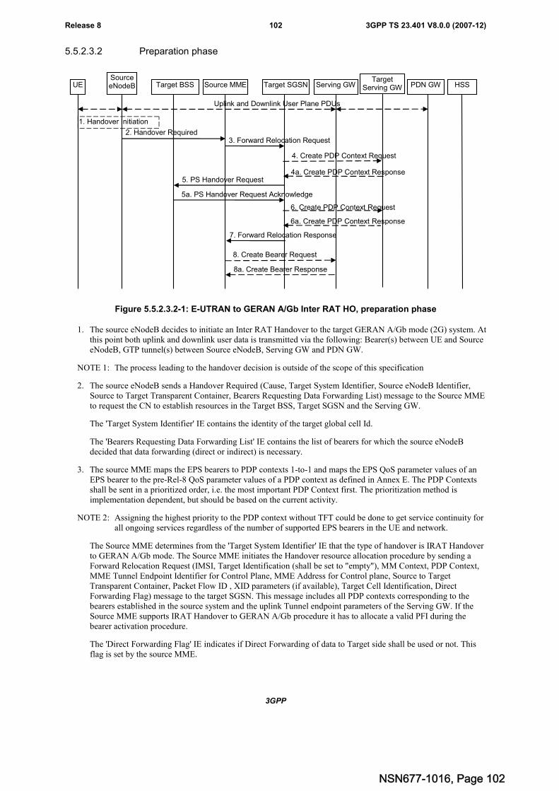
3GPP
3GPP TS 23.401 V8.0.0 (2007-12)102Release 8
5.5.2.3.2 Preparation phase
UESourceeNodeB Target BSS Source MME Target SGSN Serving GW HSS
1. Handover Initiation
2. Handover Required3. Forward Relocation Request
5. PS Handover Request
5a. PS Handover Request Acknowledge
8. Create Bearer Request
7. Forward Relocation Response
PDN GW
8a. Create Bearer Response
Uplink and Downlink User Plane PDUs
6. Create PDP Context Request
6a. Create PDP Context Response
TargetServing GW
4. Create PDP Context Request
4a. Create PDP Context Response
Figure 5.5.2.3.2-1: E-UTRAN to GERAN A/Gb Inter RAT HO, preparation phase
1. The source eNodeB decides to initiate an Inter RAT Handover to the target GERAN A/Gb mode (2G) system. Atthis point both uplink and downlink user data is transmitted via the following: Bearer(s) between UE and SourceeNodeB, GTP tunnel(s) between Source eNodeB, Serving GW and PDN GW.
NOTE 1: The process leading to the handover decision is outside of the scope of this specification
2. The source eNodeB sends a Handover Required (Cause, Target System Identifier, Source eNodeB Identifier,Source to Target Transparent Container, Bearers Requesting Data Forwarding List) message to the Source MMEto request the CN to establish resources in the Target BSS, Target SGSN and the Serving GW.
The 'Target System Identifier' IE contains the identity of the target global cell Id.
The 'Bearers Requesting Data Forwarding List' IE contains the list of bearers for which the source eNodeBdecided that data forwarding (direct or indirect) is necessary.
3. The source MME maps the EPS bearers to PDP contexts 1-to-1 and maps the EPS QoS parameter values of anEPS bearer to the pre-Rel-8 QoS parameter values of a PDP context as defined in Annex E. The PDP Contextsshall be sent in a prioritized order, i.e. the most important PDP Context first. The prioritization method isimplementation dependent, but should be based on the current activity.
NOTE 2: Assigning the highest priority to the PDP context without TFT could be done to get service continuity forall ongoing services regardless of the number of supported EPS bearers in the UE and network.
The Source MME determines from the 'Target System Identifier' IE that the type of handover is IRAT Handoverto GERAN A/Gb mode. The Source MME initiates the Handover resource allocation procedure by sending aForward Relocation Request (IMSI, Target Identification (shall be set to "empty"), MM Context, PDP Context,MME Tunnel Endpoint Identifier for Control Plane, MME Address for Control plane, Source to TargetTransparent Container, Packet Flow ID , XID parameters (if available), Target Cell Identification, DirectForwarding Flag) message to the target SGSN. This message includes all PDP contexts corresponding to thebearers established in the source system and the uplink Tunnel endpoint parameters of the Serving GW. If theSource MME supports IRAT Handover to GERAN A/Gb procedure it has to allocate a valid PFI during thebearer activation procedure.
The 'Direct Forwarding Flag' IE indicates if Direct Forwarding of data to Target side shall be used or not. Thisflag is set by the source MME.
NSN677-1016, Page 102
3GPP
3GPP TS 23.401 V8.0.0 (2007-12)103Release 8
The MM context contains security related information, e.g. supported ciphering algorithms, as described inTS 29.060 [14]. The relation between GSM and EPS security parameters is FFS.
The target SGSN selects the ciphering algorithm to use. This algorithm will be sent transparently from the targetSGSN to the UE in the NAS container for Handover (part of the Target to Source Transparent Container). TheIOV-UI parameter, generated in the target SGSN, is used as input to the ciphering procedure and it will also betransferred transparently from the target SGSN to the UE in the NAS container for Handover.
Editor's note: This needs to be aligned with security requirements for Release 8.
Editor's note: It is FFS how the mapping of individual parameters and bearer identifiers is done. It is FFS how thebearer identifiers are mapped.
When the target SGSN receives the Forward Relocation Request message the required PDP, MM, SNDCP andLLC contexts are established and a new P-TMSI is allocated for the UE. When this message is received by thetarget SGSN, it begins the process of establishing PFCs for all PDP contexts.
When the target SGSN receives the Forward Relocation Request message it extracts from the PDP Contexts theNSAPIs and SAPIs and PFIs to be used in the target SGSN. If for a given PDP Context the target SGSN does notreceive a PFI from the source MME, it shall not request the target BSS to allocate TBF resources correspondingto that PDP Context. If none of the PDP Contexts forwarded from the source MME has a valid PFI allocated thetarget SGSN shall consider this as a failure case and the request for Handover shall be rejected.
If when an SAPI and PFI was available at the source MME but the target SGSN does not support the same SAPIand PFI for a certain NSAPI as the source MME, the target SGSN shall continue the Handover procedure onlyfor those NSAPIs for which it can support the same PFI and SAPI as the source MME. All PDP contexts forwhich no resources are allocated by the target SGSN or for which it cannot support the same SAPI and PFI (i.e.the corresponding NSAPIs are not addressed in the response message of the target SGSN), are maintained andthe related SAPIs and PFIs are kept. These PDP contexts may be modified or deactivated by the target SGSN viaexplicit SM procedures upon RAU procedure.
The source MME shall indicate the current XID parameter settings if available (i.e. those XID parametersreceived during a previous IRAT Handover procedure) to the target SGSN. If the target SGSN can accept allXID parameters as indicated by the source MME, the target SGSN shall create a NAS container for Handoverindicating 'Reset to the old XID parameters'. Otherwise, if the target SGSN cannot accept all XID parametersindicated by the source MME or if no XID parameters were indicated by the source MME, the target SGSN shallcreate a NAS container for Handover indicating Reset (i.e. reset to default parameters).
4. The target SGSN determines if the Serving GW is relocated, e.g., due to PLMN change. If the Serving GW isrelocated, the target SGSN selects the target Serving GW as described under clause 4.3.8.2 on "Serving GWselection function", and sends a Create PDP Context Request message (IMSI, SGSN Tunnel Endpoint Identifierfor Control Plane, SGSN Address for Control plane, PDN GW address(es) for user plane, PDN GW UL TEID(s)for user plane, PDN GW address(es) for control plane, and PDN GW TEID(s) for control plane) to the targetServing GW.
4a. The target Serving GW allocates its local resources and returns a Create PDP Context Response (Serving GWaddress(es) for user plane, Serving GW UL TEID(s) for user plane, Serving GW DL TEID(s), Serving GWAddress for control plane, Serving GW TEID for control plane) message to the target SGSN.
5. The target SGSN establishes the PDP context(s) in the indicated order. The SGSN deactivates the PDP contextswhich cannot be established.
The Target SGSN requests the Target BSS to establish the necessary resources (PFCs) by sending the messagePS Handover Request (Local TLLI, IMSI, Cause, Target Cell Identifier, PFCs to be set-up list, Source to TargetTransparent Container and NAS container for handover). The target SGSN shall not request resources for whichthe Activity Status Indicator within a PDP Context indicates that no active bearer exists on the source side forthat PDP context.
Based upon the ABQP for each PFC the target BSS makes a decision about which PFCs to assign radioresources. The algorithm by which the BSS decides which PFCs that need resources is implementation specific.Due to resource limitations not all downloaded PFCs will necessarily receive resource allocation. The target BSSallocates TBFs for each PFC that it can accommodate.
NSN677-1016, Page 103
3GPP
3GPP TS 23.401 V8.0.0 (2007-12)104Release 8
The target BSS shall prepare the 'Target to Source Transparent Container' which contains a PS HandoverCommand including the EPC part (NAS container for Handover) and the RN part (Handover Radio Resources).
5a. The Target BSS allocates the requested resources and returns the applicable parameters to the Target SGSN inthe message PS Handover Request Acknowledge (Local TLLI, List of set-up PFCs, Target to SourceTransparent Container). Upon sending the PS Handover Request Acknowledge message the target BSS shall beprepared to receive downlink LLC PDUs from the target SGSN for the accepted PFCs.
Any PDP contexts for which a PFC was not established are maintained in the target SGSN and the related SAPIsand PFIs are kept. These PDP contexts may be modified or deactivated by the target SGSN via explicit SMprocedures upon the completion of the routing area update (RAU) procedure.
6. If indirect forwarding applies the target SGSN sends a Create PDP Context Request message (IMSI, SGSNTunnel Endpoint Identifier for Control Plane, SGSN Address for Control plane, Target SGSN Address(es) andTEID(s) for DL user plane) to the target Serving GW.
6a. The target Serving GW returns a Create PDP Context Response (Cause) message to the target SGSN.
7. The Target SGSN sends the message Forward Relocation Response (Cause, SGSN Tunnel Endpoint Identifierfor Control Plane, SGSN Address for Control Plane, Target to Source Transparent Container (in the 'BSSContainer' IE), BSSGP Cause, List of set-up PFIs, Address(es) and TEID(s) for User Traffic Data Forwarding)to the Source MME.
If 'Direct Forwarding' is applicable, then the IEs 'Address(es) and TEID(s) for User Traffic Data Forwarding'contains the GTP-U tunnel endpoint parameters to the Target SGSN. Otherwise the IEs 'Address(es) andTEID(s) for User Traffic Data Forwarding' may contain the GTP-U tunnel endpoint parameters to the ServingGW (or to the Target Serving GW in case of Serving GW re-location) .
The target SGSN activates the allocated LLC/SNDCP engines as specified in TS 44.064 [23] for an SGSNoriginated Reset or 'Reset to the old XID parameters'.
8. If "Direct Forwarding" is not applicable, the Source MME sends the message Create Bearer Request (Cause,Address(es) and TEID(s) for Data Forwarding (see step 7), NSAPI(s)) to the Serving GW used for indirectpacket forwarding. The Cause indicates that the bearer(s) are subject to data forwarding.
Indirect forwarding may be performed via a Serving GW which is different from the Serving GW used as theanchor point for the UE.
8a. The Serving GW returns the forwarding user plane parameters by sending the message Create Bearer Response(Cause, Serving GW Address(es) and TEID(s) for Data Forwarding). If the Serving GW doesn't support dataforwarding, an appropriate cause value shall be returned and the Serving GW Address(es) and TEID(s) will notbe included in the message.
NSN677-1016, Page 104
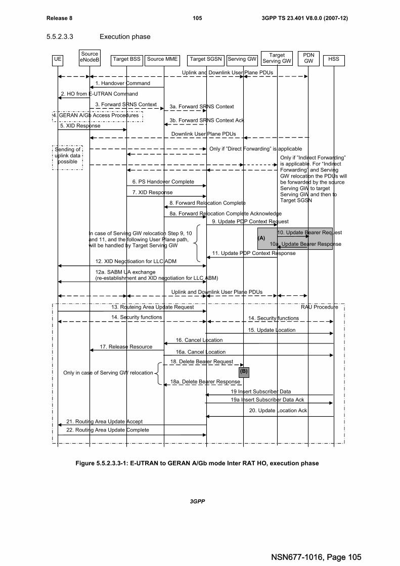
3GPP
3GPP TS 23.401 V8.0.0 (2007-12)105Release 8
5.5.2.3.3 Execution phase
UESourceeNodeB Target BSS Source MME Target SGSN Serving GW HSS
PDNGW
Uplink and Downlink User Plane PDUs
1. Handover Command
2. HO from E-UTRAN Command
Sending ofuplink data
possible
4. GERAN A/Gb Access Procedures
3a. Forward SRNS Context
3b. Forward SRNS Context Ack5. XID Response
6. PS Handover Complete
8. Forward Relocation Complete
8a. Forward Relocation Complete Acknowledge
13. Routeing Area Update Request
9. Update PDP Context Request
11. Update PDP Context Response
Uplink and Downlink User Plane PDUs
3. Forward SRNS Context
7. XID Response
RAU Procedure
17. Release Resource
12. XID Negotioation for LLC ADM
12a. SABM UA exchange(re-establishment and XID negotiation for LLC ABM)
Downlink User Plane PDUs
Only if ”Direct Forwarding” is applicable
Only if ”Indirect Forwarding”is applicable. For “IndirectForwarding” and ServingGW relocation the PDUs willbe forwarded by the sourceServing GW to targetServing GW and then toTarget SGSN
14. Security functions
21. Routing Area Update Accept
14. Security functions
15. Update Location
16. Cancel Location
16a. Cancel LocationAck
20. Update Location Ack
22. Routing Area Update Complete
TargetServing GW
In case of Serving GW relocation Step 9, 10and 11, and the following User Plane path,will be handled by Target Serving GW
(A)
19 Insert Subscriber Data
19a Insert Subscriber Data Ack
18. Delete Bearer Request
18a. Delete Bearer Response
Only in case of Serving GW relocation
10. Update Bearer Request
10a. Update Bearer Response
(B)
Figure 5.5.2.3.3-1: E-UTRAN to GERAN A/Gb mode Inter RAT HO, execution phase
NSN677-1016, Page 105
3GPP
3GPP TS 23.401 V8.0.0 (2007-12)106Release 8
NOTE 1: For a PMIP-based S5/S8, procedure steps (A) and (B) are defined in TS 23.402 [2]. Step (B) shows PCRFinteraction in the case of PMIP-based S5/S8. Steps 10 and 10a concern GTP based S5/S8
Editor's note: It's FFS how the interaction with HSS is affected by the Idle-mode Signalling Reduction (ISR)function.
The source eNodeB continues to receive downlink and uplinkuser plane PDUs.
1. The Source MME completes the preparation phase towards Source eNodeB by sending the message HandoverCommand (Target to Source Transparent Container (PS Handover Command with RN part and EPC part),Bearers Subject to Data Forwarding List). The "Bearers Subject to Data forwarding list" may be included in themessage and it shall be a list of 'Address(es) and TEID(s) for user traffic data forwarding' received from targetside in the preparation phase (Forward Relocation Response message).
Source eNodeB initiate data forwarding for the bearers specified in the "Bearers Subject to Data ForwardingList". The data forwarding may go directly i.e. to target SGSN or alternatively go via the Serving GW if sodecided by source MME and/or target SGSN in the preparation phase.
2. The Source eNodeB will give a command to the UE to handover to the Target Access System via the messageHO from E-UTRAN Command. This message includes a transparent container including radio aspect parametersthat the Target BSS has set-up in the preparation phase (RN part). This message also includes the XID and IOV-UI parameters received from the Target SGSN (EPC part).
Upon the reception of the HO from E-UTRAN Command message containing the Handover Command message,the UE shall associate its bearer IDs to the respective PFIs based on the relation with the NSAPI and shallsuspend the uplink transmission of the user plane data.
3. The Source eNodeB may inform the Source MME which then informs the Target SGSN regarding "deliveryorder" parameters in the message Forward SRNS Context.
The need for step 3 is FFS.
4. The UE moves to the Target GERAN A/Gb (2G) system and performs executes the handover according to theparameters provided in the message delivered in step 2. The procedure is the same as in step 6 in subclause5.3.2.2 in TS 43.129 [8] with the additional function of association of the received PFI and existing Bearer Idrelated to the particular NSAPI. Relation between NSAPI, PFI and Bearer Id is FFS.
5. After accessing the cell using access bursts and receiving timing advance information from the BSS in step 4, theUE processes the NAS container and then sends one XID response message to the target SGSN via target BSS.The UE sends this message immediately after receiving the Packet Physical Information message containing thetiming advance or, in the synchronised network case, immediately if the PS Handover Access message is notrequired to be sent.
Upon sending the XID Response message, the UE shall resume the user data transfer only for those NSAPIs forwhich there are radio resources allocated in the target cell. For NSAPIs using LLC ADM, for which radioresources were not allocated in the target cell, the MS may request for radio resources using the legacyprocedures.
If the Target SGSN indicated XID Reset (i.e. reset to default XID parameters) in the NAS container included inthe HO from E-UTRAN Command message, and to avoid collision cases the mobile station may avoid triggeringXID negotiation for any LLC SAPI used in LLC ADM, but wait for the SGSN to do so (see step 12). In any casethe mobile station may avoid triggering XID negotiation for any LLC SAPI used in LLC ABM, but wait for theSGSN to do so (see step 12a).
This step is the same as specified in clause 5.3.2.2 in TS 43.129 [8].
6. Upon reception of the first correct RLC/MAC block (sent in normal burst format) from the UE to the TargetBSS, the Target BSS informs the Target SGSN by sending the message PS Handover Complete (IMSI, andLocal TLLI).
7. The Target BSS also relays the message XID Response to the Target SGSN. Note, the message in step 6 and 7may arrive in any order in the Target SGSN.
8. Then the Target SGSN knows that the UE has arrived to the target side and Target SGSN informs the SourceMME by sending the message Forward Relocation Complete. The Source MME will also acknowledge that
NSN677-1016, Page 106
3GPP
3GPP TS 23.401 V8.0.0 (2007-12)107Release 8
information. A timer in source MME is started to supervise when resources in Source eNodeB and SourceServing GW (in case of Serving GW relocation) shall be released (normally this will occur when Source MMEreceives the message Cancel Location from HSS). Further action in the Source MME continues at step 16.
9. The Target SGSN will now complete the Handover procedure by informing the Serving GW (for Serving GWrelocation this will be the Target Serving GW) that the Target SGSN is now responsible for all the PDP Contextthe UE have established. This is performed in the message Update PDP Context Request (Serving GW TunnelEndpoint Identifier for Control Plane, NSAPI(s), SGSN Address for Control Plane, SGSN Address(es) andTEID(s) for User Traffic, and RAT type).
10. The Serving GW (for Serving GW relocation this will be the Target Serving GW) may inform the PDN GW thechange of, for example, in case of Serving GW relocation or the RAT type, that e.g. can be used for charging, bysending the message Update Bearer Request. The PDN GW must acknowledge the request with the messageUpdate Bearer Response.
If PCC infrastructure is used, the PDN GW informs the PCRF about the change of, for example, the RAT type.
11. The Serving GW (for Serving GW relocation this will be the Target Serving GW) acknowledges the user planeswitch to the Target SGSN via the message Update PDP Context Response (Cause, Serving GW TunnelEndpoint Identifier for Control Plane, Serving GW Address for Control Plane, Protocol Configuration Options).At this stage the user plane path is established for all PDP contexts between the UE, Target BSS, Target SGSN,Serving GW (for Serving GW relocation this will be the Target Serving GW) and PDN GW.
12. If the Target SGSN indicated XID Reset (i.e. reset to default XID parameters) in the NAS container included inthe HO from E-UTRAN Command message, then on receipt of the PS Handover Complete the Target SGSNinitiates an LLC/SNDCP XID negotiation for each LLC SAPI used in LLC ADM. In this case if the TargetSGSN wants to use the default XID parameters, it shall send an empty XID Command. If the Target SGSNindicated 'Reset to the old XID parameters' in the NAS container, no further XID negotiation is required for LLCSAPIs used in LLC ADM only.
12a. The Target SGSN (re-)establishes LLC ABM for the PDP contexts which use acknowledged informationtransfer. During the exchange of SABM and UA the SGSN shall perform LLC/SNDCP XID negotiation.
These steps (12 and 12a) are the same as specified in clause 5.3.2.2 in TS 43.129 [8].
13. The UE sends a Routeing Area Update Request message to the target SGSN informing it that the UE is locatedin a new routing area. The UE shall send this message immediately after step 5.
The target SGSN knows that a Handover has been performed for this UE and can therefore exclude the contextprocedures between source MME and target SGSN which normally are used within the RA Update procedure.
14. At this point the target SGSN may optionally invoke security function. The security function can be deferred andperformed at any later time as well. Procedures are defined in the clause "Security Function".
NOTE 2: During a security function the SGSN has to suspend the downlink transmission of user data.
15. The target SGSN informs the HSS of the change of CN node by sending Update Location (SGSN Number,SGSN Address, IMSI) message to the HSS.
16. The HSS sends a Cancel Location (IMSI, Cancellation Type) message to the source MME with CancellationType set to Update Procedure. The source MME acknowledges with a Cancel Location Acknowledge (IMSI)message.
17. After the source MME has received the Cancel Location message or the timer started at Step 8 expires, thesource MME sends a Release Resources message to the source eNodeB. The Source eNodeB releases itsresources related to the UE.
18. This step is only performed in case of Serving GW relocation. When the source MME removes the MM context,the source MME deletes the EPS bearer resources by sending Delete Bearer Request (Cause, TEID) messages tothe Source Serving GW. The source MME shall indicate to the Source Serving GW that the Source Serving GWshall not initiate a delete procedure towards the PDN GW. The Source Serving GW acknowledges with DeleteBearer Response (TEID) messages.
NSN677-1016, Page 107
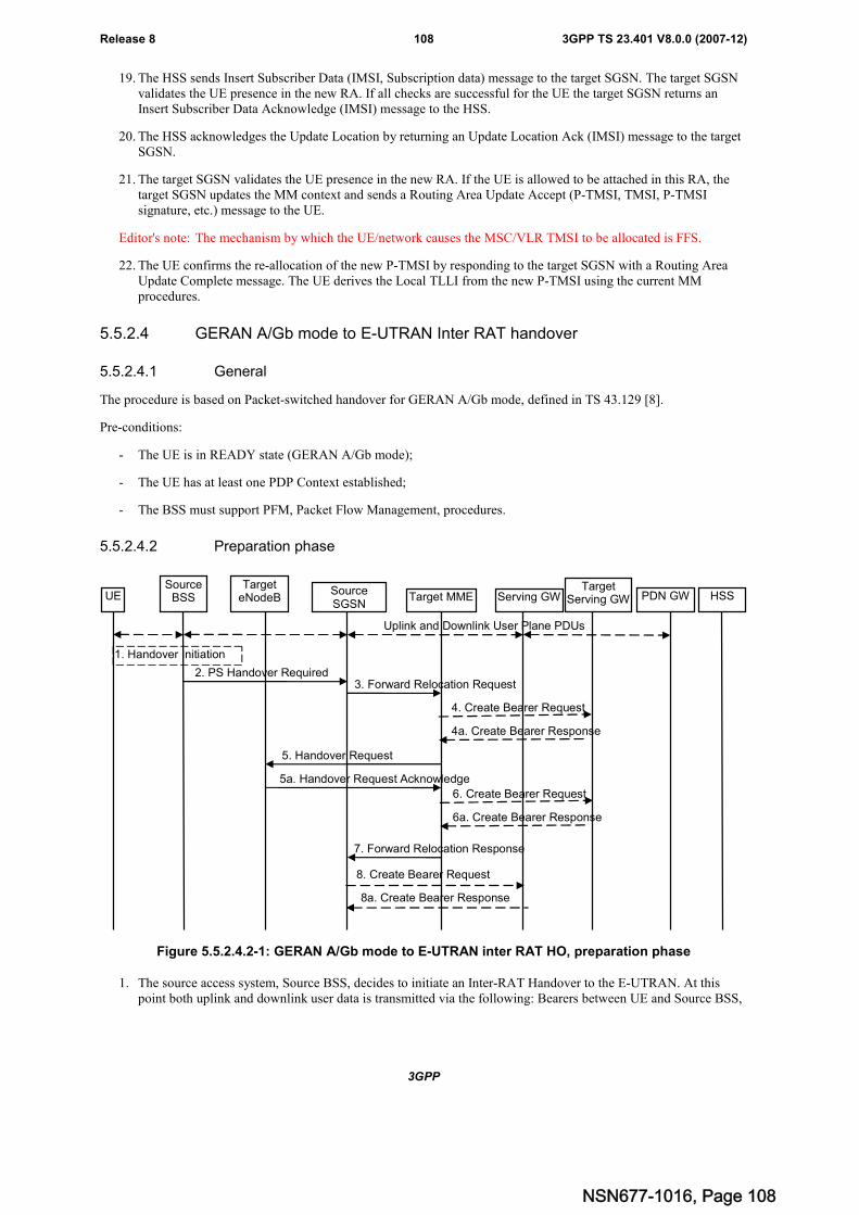
3GPP
3GPP TS 23.401 V8.0.0 (2007-12)108Release 8
19. The HSS sends Insert Subscriber Data (IMSI, Subscription data) message to the target SGSN. The target SGSNvalidates the UE presence in the new RA. If all checks are successful for the UE the target SGSN returns anInsert Subscriber Data Acknowledge (IMSI) message to the HSS.
20. The HSS acknowledges the Update Location by returning an Update Location Ack (IMSI) message to the targetSGSN.
21. The target SGSN validates the UE presence in the new RA. If the UE is allowed to be attached in this RA, thetarget SGSN updates the MM context and sends a Routing Area Update Accept (P-TMSI, TMSI, P-TMSIsignature, etc.) message to the UE.
Editor's note: The mechanism by which the UE/network causes the MSC/VLR TMSI to be allocated is FFS.
22. The UE confirms the re-allocation of the new P-TMSI by responding to the target SGSN with a Routing AreaUpdate Complete message. The UE derives the Local TLLI from the new P-TMSI using the current MMprocedures.
5.5.2.4 GERAN A/Gb mode to E-UTRAN Inter RAT handover
5.5.2.4.1 General
The procedure is based on Packet-switched handover for GERAN A/Gb mode, defined in TS 43.129 [8].
Pre-conditions:
- The UE is in READY state (GERAN A/Gb mode);
- The UE has at least one PDP Context established;
- The BSS must support PFM, Packet Flow Management, procedures.
5.5.2.4.2 Preparation phase
UESource
BSSTarget
eNodeBSourceSGSN
Target MME Serving GW HSS
1. Handover Initiation
2. PS Handover Required3. Forward Relocation Request
5. Handover Request
5a. Handover Request Acknowledge
8. Create Bearer Request
7. Forward Relocation Response
PDN GW
8a. Create Bearer Response
Uplink and Downlink User Plane PDUs
6. Create Bearer Request
6a. Create Bearer Response
TargetServing GW
4. Create Bearer Request
4a. Create Bearer Response
Figure 5.5.2.4.2-1: GERAN A/Gb mode to E-UTRAN inter RAT HO, preparation phase
1. The source access system, Source BSS, decides to initiate an Inter-RAT Handover to the E-UTRAN. At thispoint both uplink and downlink user data is transmitted via the following: Bearers between UE and Source BSS,
NSN677-1016, Page 108
3GPP
3GPP TS 23.401 V8.0.0 (2007-12)109Release 8
BSSGP PFC tunnel(s) between source BSS and source SGSN, GTP tunnel(s) between Source SGSN, ServingGW and PDN GW.
NOTE 1: The process leading to the handover decision is outside of the scope of this specification.
2. The source BSS sends the message PS handover Required (TLLI, Cause, Source Cell Identifier, Target eNodeBIdentifier, Source to Target Transparent Container (RN part), and active PFCs list) to Source SGSN to requestthe CN to establish resources in the Target eNodeB, Target MME and the Serving GW.
3. The Source SGSN determines from the 'Target eNodeB Identifier' IE that the type of handover is IRAT PSHandover to E-UTRAN. The Source SGSN initiates the Handover resource allocation procedure by sendingmessage Forward Relocation Request (IMSI, Target Identification, MM Context, PDP Context, SGSN TunnelEndpoint Identifier for Control Plane, SGSN Address for Control plane, Source to Target Transparent Container(RN part), Packet Flow ID, SNDCP XID parameters, LLC XID parameters, and Direct Forwarding Flag) to thetarget MME. This message includes all PDP contexts that are established in the source system indicating thePFIs and the XID parameters related to those PDP Contexts, and the uplink Tunnel endpoint parameters of theServing GW.
The PDP Contexts shall be sent in a prioritized order, i.e. the most important PDP Context first. Theprioritization method is implementation dependent, but should be based on the current activity.
NOTE 2: Assigning the highest priority to the PDP context without TFT could be done to get service continuity forall ongoing services regardless of the number of supported EPS bearers in the UE and network.
The 'Direct Forwarding Flag' IE indicates if Direct Forwarding of data to Target side shall be used or not. Thisflag is set by the source SGSN. The target MME maps the PDP contexts to the EPS bearers 1-to-1 and maps thepre-Rel-8 QoS parameter values of a PDP context to the EPS QoS parameter values of an EPS bearer as definedin Annex E. The MME establishes the EPS bearer(s) in the indicated order. The MME deactivates the EPSbearers which cannot be established.
The MM context contains security related information, e.g. supported ciphering algorithms as described inTS 29.060 [14]. The relation between GSM and EPS security parameters is FFS.
Editor's note: It is FFS if the EPS bearers are mapped 1:1 to PDP contexts. It is FFS how the mapping is done. It isFFS how the bearer identifiers are mapped.
For the PDP Context with traffic class equals 'Background', the source SGSN shall indicate via the ActivityStatus Indicator IE that EPS bearers shall be established on the target side.
4. The target MME determines if the Serving GW is relocated, e.g. due to PLMN change. If the Serving GW isrelocated, the target MME selects the target Serving GW as described under clause 4.3.8.2 on "Serving GWselection function". The target MME sends a Create Bearer Request message (IMSI, MME Tunnel EndpointIdentifier for Control Plane, MME Address for Control plane, PDN GW address(es) for user plane, PDN GWUL TEID(s) for user plane, PDN GW address for control plane, and PDN GW TEID(s) for control plane) to thetarget Serving GW.
4a. The target Serving GW allocates its local resources and returns them in a Create Bearer Response (Serving GWaddress(es) for user plane, Serving GW UL TEID(s) for user plane, Serving GW DL TEID(s) (in case of indirectforwarding is supported), Serving GW Address for control plane, Serving GW TEID for control plane) messageto the target MME.
5. The Target MME will request the Target eNodeB to establish the Bearer(s) by sending the message HandoverRequest (UE Identifier, Cause, CN Domain Indicator, Integrity protection information (i.e. IK and allowedIntegrity Protection algorithms), Encryption information (i.e. CK and allowed Ciphering algorithms), EPSBearers to be setup list, Source to Target Transparent Container). The Target MME shall not request resourcesfor which the Activity Status Indicator within a PDP Context indicates that no active bearer exists on the sourceside for that PDP Context.
For each EPS bearer requested to be established, 'EPS Bearers To Be Setup' IE shall contain information such asID, bearer parameters, Transport Layer Address, and S1 Transport Association. The Transport Layer Address isthe Serving GW Address for user data, and the S1 Transport Association corresponds to the uplink TunnelEndpoint Identifier Data.
The ciphering and integrity protection keys will be sent transparently from the target eNodeB to the UE in theTarget to Source Transparent Container, and in the message PS Handover Command from source BSS to the UE.
NSN677-1016, Page 109
3GPP
3GPP TS 23.401 V8.0.0 (2007-12)110Release 8
This will then allow data transfer to continue in the new RAT/mode target cell without requiring a new AKA(Authentication and Key Agreement) procedure.
5a. The Target eNodeB allocates the request resources and returns the applicable parameters to the Target MME inthe message Handover Request Acknowledge (Target to Source Transparent Container, EPS Bearers setup list,EPS Bearers failed to setup list). Upon sending the Handover Request Acknowledge message the target eNodeBshall be prepared to receive downlink GTP PDUs from the Serving GW for the accepted EPS bearers.
6. If indirect forwarding applies, the target MME sends a Create Bearer Request message (IMSI, MME TunnelEndpoint Identifier for Control Plane, MME Address for Control plane, Target eNodeB Address(es), TEID(s) forDL user plane) to the target Serving GW.
6a. The target Serving GW returns a Create Bearer Response (Cause) message to the target MME.
7. The Target MME sends the message Forward Relocation Response (Cause, List of Set Up PFCs, MME TunnelEndpoint Identifier for Control Plane, S1-AP cause, MME Address for control plane, Target to SourceTransparent Container, Address(es) and TEID(s) for Data Forwarding) to the Source SGSN.
If 'Direct Forwarding' is applicable, then the IEs 'Address(es) and TEID(s) for Data Forwarding' contains theGTP-U tunnel endpoint parameters to the eNodeB. Otherwise the IEs 'Address(es) and TEID(s) for DataForwarding' may contain the GTP-U tunnel endpoint parameters to the Serving GW (or to the Target ServingGW for Serving GW re-location).
8. If "Direct Forwarding" is not applicable, the source SGSN shall send the message Create Bearer Request (Cause,Address(es) and TEID(s) for Data Forwarding (see step 7), NSAPI(s)) to the Serving GW used for indirectpacket forwarding. The Cause shall indicate that the Bearer is subject to data forwarding.
Indirect forwarding may be performed via a Serving GW which is different from the Serving GW used as theanchor point for the UE.
8a. The Serving GW returns the forwarding user plane parameters by sending the message Create Bearer Response(Cause, Serving GW Address(es) and TEID(s) for Data Forwarding). If the Serving GW doesn't support dataforwarding, an appropriate cause value shall be returned and the Serving GW Address(es) and TEID(s) will notbe included in the message.
NSN677-1016, Page 110
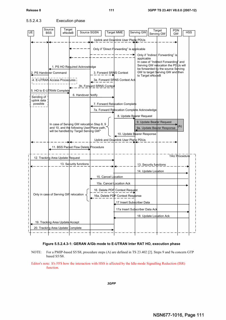
3GPP
3GPP TS 23.401 V8.0.0 (2007-12)111Release 8
5.5.2.4.3 Execution phase
UESource
BSSTarget
eNodeB Source SGSN Target MME Serving GW HSSPDNGW
Uplink and Downlink User Plane PDUs
1. PS HO Required Acknowledge
2. PS Handover Command
Sending ofuplink data
possible
4. E-UTRAN Access Procedures
3. Forward SRNS Context
3a. Forward SRNS Context Ack
5. HO to E-UTRAN Complete
6. Handover Notify
7. Forward Relocation Complete
7a. Forward Relocation Complete Acknowledge
11. BSS Packet Flow Delete Procedure
12. Tracking Area Update Request
8. Update Bearer Request
9. Update Bearer Request
9a. Update Bearer Response
10. Update Bearer Response
Uplink and Downlink User Plane PDUs
TAU Procedure
13. Security functions
19. Tracking Area Update Accept
13. Security functions
14. Update Location
15. Cancel Location
15a. Cancel Location Ack
18. Update Location Ack
20. Tracking Area Update Complete
Only if ”Direct Forwarding” is applicable
3b. Forward SRNS Context
TargetServing GW
In case of Serving GW relocation Step 8, 9and 10, and the following User Plane path,will be handled by Target Serving GW"
(A)
17 Insert Subscriber Data
17a Insert Subscriber Data Ack
16. Delete PDP Context Request
16a. Delete PDP Context ResponseOnly in case of Serving GW relocation
Only if ”Indirect Forwarding” isapplicableIn case of “Indirect Forwarding” andServing GW relocation the PDUs willbe forwarded by the source ServingGW to target Serving GW and thento Target eNodeB
Figure 5.5.2.4.3-1: GERAN A/Gb mode to E-UTRAN Inter RAT HO, execution phase
NOTE: For a PMIP-based S5/S8, procedure steps (A) are defined in TS 23.402 [2]. Steps 9 and 9a concern GTPbased S5/S8.
Editor's note: It's FFS how the interaction with HSS is affected by the Idle-mode Signalling Reduction (ISR)function.
NSN677-1016, Page 111
3GPP
3GPP TS 23.401 V8.0.0 (2007-12)112Release 8
The source SGSN continues to receive downlink and uplink user plane PDUs.
When source SGSN receives the Forward Relocation Response message it may start downlink N-PDU relay andduplication to the target eNodeB (in case of Direct Forwarding) or via the Serving GW (in case Indirect Forwarding),and the target eNodeB may start blind transmission of downlink user data towards the UE over the allocated radiochannels.
1. The Source SGSN completes the preparation phase towards Source BSS by sending the message PS HORequired Acknowledge (TLLI, List of Set Up PFCs, Target to Source Transparent Container). This messageincludes all PFIs that could be established on the Target side.
Before sending the PS Handover Required Acknowledge message, the source SGSN may suspend downlink datatransfer for any PDP contexts.
Before sending the PS Handover Command message to the UE the source BSS, may try to empty the downlinkBSS buffer for any BSS PFCs.
2. The Source BSS will command the UE to handover to the target eNodeB via the message PS HandoverCommand. The access system specific message to UE includes a transparent container including radio aspectparameters that the Target eNodeB has set-up in the preparation phase. The procedures for this are FFS.
3. Source SGSN informs the Target MME/Target eNodeB regarding source access system contexts in the messageForward SRNS Context.
The need for this step is FFS.
4. The UE moves to the E-UTRAN and performs access procedures toward Target eNodeB.
5. When the UE has got access to Target eNodeB it sends the message HO to E-UTRAN Complete.
6. When the UE has successfully accessed the Target eNodeB, the Target eNodeB informs the Target MME bysending the message Handover Notify.
7. Then the Target MME knows that the UE has arrived to the target side and Target MME informs the SourceSGSN by sending the message Forward Relocation Complete. The Source SGSN will also acknowledge thatinformation. When the Forward Relocation Complete message has been received and there is no longer any needfor the SGSN to forward data, the SGSN stops data forwarding. A timer in source SGSN is started to supervisewhen resources in the Source Serving GW (in case of Serving GW relocation) shall be released (normally thiswill occur when Source SGSN receives the message Cancel Location from HSS). Further action in the SourceSGSN continues at step 11.
8. The Target MME will now complete the Handover procedure by informing the Serving GW (for Serving GWrelocation this will be the Target Serving GW) that the Target MME is now responsible for all the EPS bearersthe UE have established. This is performed in the message Update Bearer Request (Cause, MME TunnelEndpoint Identifier for Control Plane, NSAPI(s), MME Address for Control Plane, eNodeB Address(es) andTEID(s) for User Traffic, and RAT type).
9. The Serving GW (for Serving GW relocation this will be the Target Serving GW) informs the PDN GW(s) thechange of, for example, for Serving GW relocation or the RAT type, that e.g. can be used for charging, bysending the message Update Bearer Request. The PDN GW must acknowledge the request with the messageUpdate Bearer Response.
If PCC infrastructure is used, the PDN GW informs the PCRF about the change of, for example, the RAT type.
10. The Serving GW (for Serving GW relocation this will be the Target Serving GW) acknowledges the user planeswitch to the Target MME via the message Update Bearer Response (Cause, Serving GW Tunnel EndpointIdentifier for Control Plane, Serving GW (for Serving GW relocation this will be the Target Serving GW)Address for Control Plane, Protocol Configuration Options). At this stage the user plane path is established forall bearers between the UE, Target eNodeB, Serving GW (for Serving GW relocation this will be the TargetServing GW) and PDN GW.
11. The Source SGSN will clean-up all its resources towards Source BSS by performing the BSS Packet FlowDelete procedure.
NSN677-1016, Page 112
3GPP
3GPP TS 23.401 V8.0.0 (2007-12)113Release 8
12. The UE sends a Tracking Area Update Request message to the target MME informing it that the UE is located ina new tracking area. The UE shall send this message immediately after step 5.
The target MME knows that a Handover has been performed for this UE and can therefore exclude the contextprocedures between source SGSN and target MME which normally are used within the TA Update procedure.
13. At this point the target MME may optionally invoke security function. The security function can be deferred andperformed at any later time as well. Procedures are defined in the clause "Security Function".
14. The target MME informs the HSS of the change of CN node by sending Update Location (MME Address, IMSI)message to the HSS.
15. The HSS sends a Cancel Location (IMSI, Cancellation Type) message to the source SGSN with CancellationType set to Update Procedure. The source SGSN acknowledges with a Cancel Location Acknowledge (IMSI)message.
16. This step is only performed in case of Serving GW relocation. When the source SGSN removes the MM context,the source SGSN deletes the EPS bearer resources by sending Delete PDP Context Request (Cause, TEID)messages to the Source Serving GW. The source SGSN shall indicate to the Source Serving GW that the SourceServing GW shall not initiate a delete procedure towards the PDN GW. The Source Serving GW acknowledgeswith Delete PDP Context Response (TEID) messages.
17. The HSS sends Insert Subscriber Data (IMSI, Subscription data) message to the target MME. The target MMEvalidates the UE presence in the new TA. If all checks are successful for the UE the target MME returns anInsert Subscriber Data Acknowledge (IMSI) message to the HSS.
18. The HSS acknowledges the Update Location by returning an Update Location Ack (IMSI) message to the targetMME.
19. The target MME validates the UE presence in the new TA. If the UE is allowed to be attached in this TA, thetarget MME updates the MM context and sends a Tracking Area Update Accept (GUTI, TAI-List, etc.) messageto the UE.
20. The UE confirms the re-allocation of the new GUTI by responding to the target MME with a Tracking AreaUpdate Complete message.
5.6 Information storage
Editor's Note: This section describes the context information that is stored in the different nodes, eg in PDN GW,eNodeB, UE, etc.It also gives a high level overview of recovery and restoration procedures.
This clause describes information storage structures required for the EPS when 3GPP access only is deployed.Information storage for the case where non 3GPP accesses are deployed is in TS 23.402 [2]
5.6.1 HSS
IMSI is the prime key to the data stored in the HSS. The data held in the HSS is defined in Table 5.6.1-1 here below.
Editor's Note: The tables here below are for the moment applicable to EUTRAN in standalone operation only.
NSN677-1016, Page 113
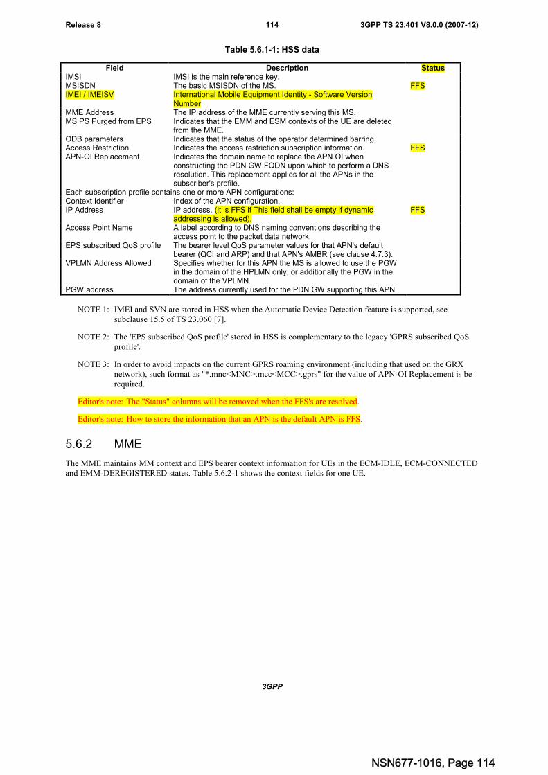
3GPP
3GPP TS 23.401 V8.0.0 (2007-12)114Release 8
Table 5.6.1-1: HSS data
NOTE 1: IMEI and SVN are stored in HSS when the Automatic Device Detection feature is supported, seesubclause 15.5 of TS 23.060 [7].
NOTE 2: The 'EPS subscribed QoS profile' stored in HSS is complementary to the legacy 'GPRS subscribed QoSprofile'.
NOTE 3: In order to avoid impacts on the current GPRS roaming environment (including that used on the GRXnetwork), such format as "*.mnc<MNC>.mcc<MCC>.gprs" for the value of APN-OI Replacement is berequired.
Editor's note: The "Status" columns will be removed when the FFS's are resolved.
Editor's note: How to store the information that an APN is the default APN is FFS.
5.6.2 MME
The MME maintains MM context and EPS bearer context information for UEs in the ECM-IDLE, ECM-CONNECTEDand EMM-DEREGISTERED states. Table 5.6.2-1 shows the context fields for one UE.
Field Description StatusIMSI IMSI is the main reference key.MSISDN The basic MSISDN of the MS. FFSIMEI / IMEISV International Mobile Equipment Identity - Software Version
NumberMME Address The IP address of the MME currently serving this MS.MS PS Purged from EPS Indicates that the EMM and ESM contexts of the UE are deleted
from the MME.ODB parameters Indicates that the status of the operator determined barringAccess Restriction Indicates the access restriction subscription information. FFSAPN-OI Replacement Indicates the domain name to replace the APN OI when
constructing the PDN GW FQDN upon which to perform a DNSresolution. This replacement applies for all the APNs in thesubscriber's profile.
Each subscription profile contains one or more APN configurations:Context Identifier Index of the APN configuration.IP Address IP address. (it is FFS if This field shall be empty if dynamic
addressing is allowed).FFS
Access Point Name A label according to DNS naming conventions describing theaccess point to the packet data network.
EPS subscribed QoS profile The bearer level QoS parameter values for that APN's defaultbearer (QCI and ARP) and that APN's AMBR (see clause 4.7.3).
VPLMN Address Allowed Specifies whether for this APN the MS is allowed to use the PGWin the domain of the HPLMN only, or additionally the PGW in thedomain of the VPLMN.
PGW address The address currently used for the PDN GW supporting this APN
NSN677-1016, Page 114
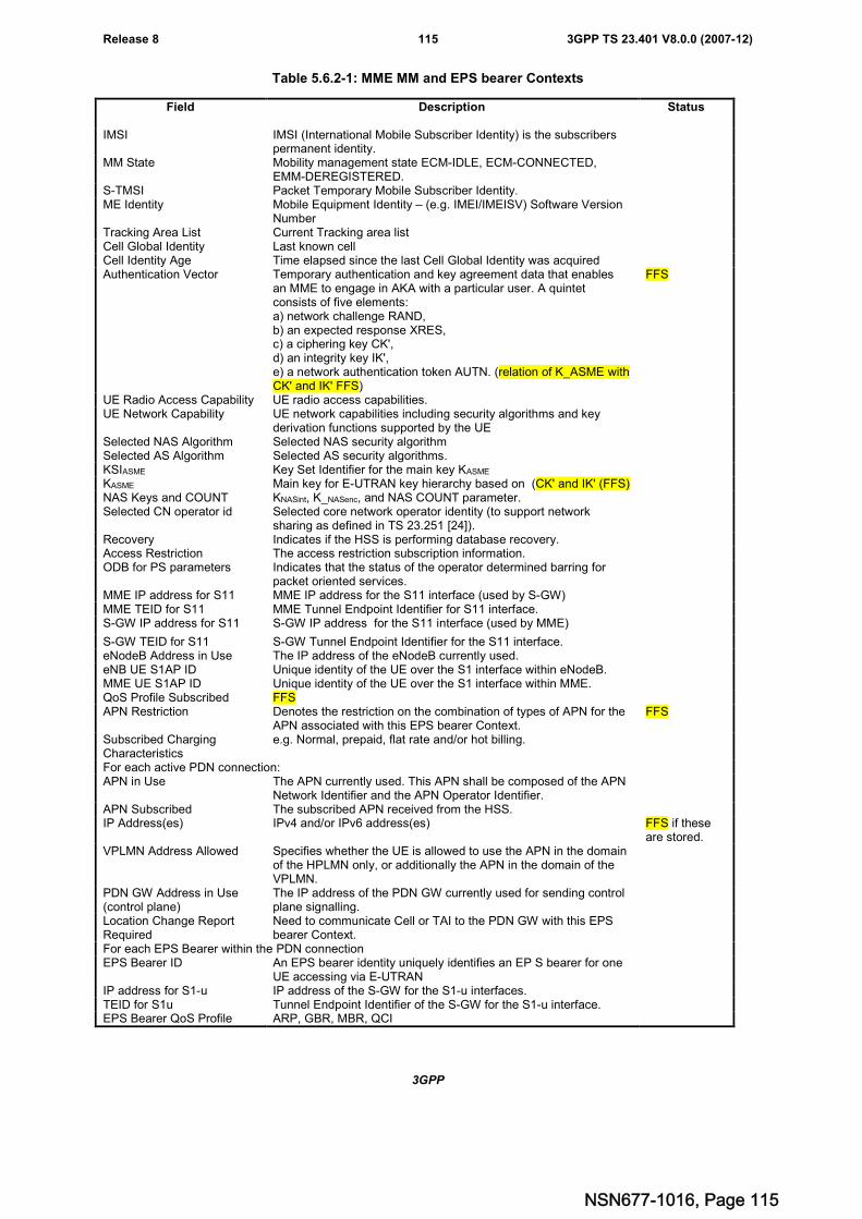
3GPP
3GPP TS 23.401 V8.0.0 (2007-12)115Release 8
Table 5.6.2-1: MME MM and EPS bearer Contexts
Field Description Status
IMSI IMSI (International Mobile Subscriber Identity) is the subscriberspermanent identity.
MM State Mobility management state ECM-IDLE, ECM-CONNECTED,EMM-DEREGISTERED.
S-TMSI Packet Temporary Mobile Subscriber Identity.ME Identity Mobile Equipment Identity – (e.g. IMEI/IMEISV) Software Version
NumberTracking Area List Current Tracking area listCell Global Identity Last known cellCell Identity Age Time elapsed since the last Cell Global Identity was acquiredAuthentication Vector Temporary authentication and key agreement data that enables
an MME to engage in AKA with a particular user. A quintetconsists of five elements:a) network challenge RAND,b) an expected response XRES,c) a ciphering key CK',d) an integrity key IK',e) a network authentication token AUTN. (relation of K_ASME withCK' and IK' FFS)
FFS
UE Radio Access Capability UE radio access capabilities.UE Network Capability UE network capabilities including security algorithms and key
derivation functions supported by the UESelected NAS Algorithm Selected NAS security algorithmSelected AS Algorithm Selected AS security algorithms.KSIASME Key Set Identifier for the main key KASME
KASME Main key for E-UTRAN key hierarchy based on (CK' and IK' (FFS)NAS Keys and COUNT KNASint, K_NASenc, and NAS COUNT parameter.Selected CN operator id Selected core network operator identity (to support network
sharing as defined in TS 23.251 [24]).Recovery Indicates if the HSS is performing database recovery.Access Restriction The access restriction subscription information.ODB for PS parameters Indicates that the status of the operator determined barring for
packet oriented services.MME IP address for S11 MME IP address for the S11 interface (used by S-GW)MME TEID for S11 MME Tunnel Endpoint Identifier for S11 interface.S-GW IP address for S11 S-GW IP address for the S11 interface (used by MME)
S-GW TEID for S11 S-GW Tunnel Endpoint Identifier for the S11 interface.eNodeB Address in Use The IP address of the eNodeB currently used.eNB UE S1AP ID Unique identity of the UE over the S1 interface within eNodeB.MME UE S1AP ID Unique identity of the UE over the S1 interface within MME.QoS Profile Subscribed FFSAPN Restriction Denotes the restriction on the combination of types of APN for the
APN associated with this EPS bearer Context.FFS
Subscribed ChargingCharacteristics
e.g. Normal, prepaid, flat rate and/or hot billing.
For each active PDN connection:APN in Use The APN currently used. This APN shall be composed of the APN
Network Identifier and the APN Operator Identifier.APN Subscribed The subscribed APN received from the HSS.IP Address(es) IPv4 and/or IPv6 address(es) FFS if these
are stored.VPLMN Address Allowed Specifies whether the UE is allowed to use the APN in the domain
of the HPLMN only, or additionally the APN in the domain of theVPLMN.
PDN GW Address in Use(control plane)
The IP address of the PDN GW currently used for sending controlplane signalling.
Location Change ReportRequired
Need to communicate Cell or TAI to the PDN GW with this EPSbearer Context.
For each EPS Bearer within the PDN connectionEPS Bearer ID An EPS bearer identity uniquely identifies an EP S bearer for one
UE accessing via E-UTRANIP address for S1-u IP address of the S-GW for the S1-u interfaces.TEID for S1u Tunnel Endpoint Identifier of the S-GW for the S1-u interface.EPS Bearer QoS Profile ARP, GBR, MBR, QCI
NSN677-1016, Page 115
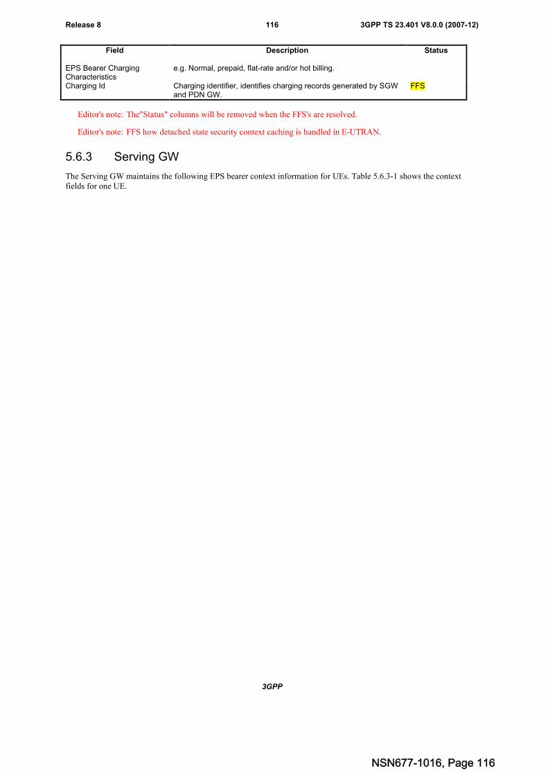
3GPP
3GPP TS 23.401 V8.0.0 (2007-12)116Release 8
Field Description Status
EPS Bearer ChargingCharacteristics
e.g. Normal, prepaid, flat-rate and/or hot billing.
Charging Id Charging identifier, identifies charging records generated by SGWand PDN GW.
FFS
Editor's note: The"Status" columns will be removed when the FFS's are resolved.
Editor's note: FFS how detached state security context caching is handled in E-UTRAN.
5.6.3 Serving GW
The Serving GW maintains the following EPS bearer context information for UEs. Table 5.6.3-1 shows the contextfields for one UE.
NSN677-1016, Page 116
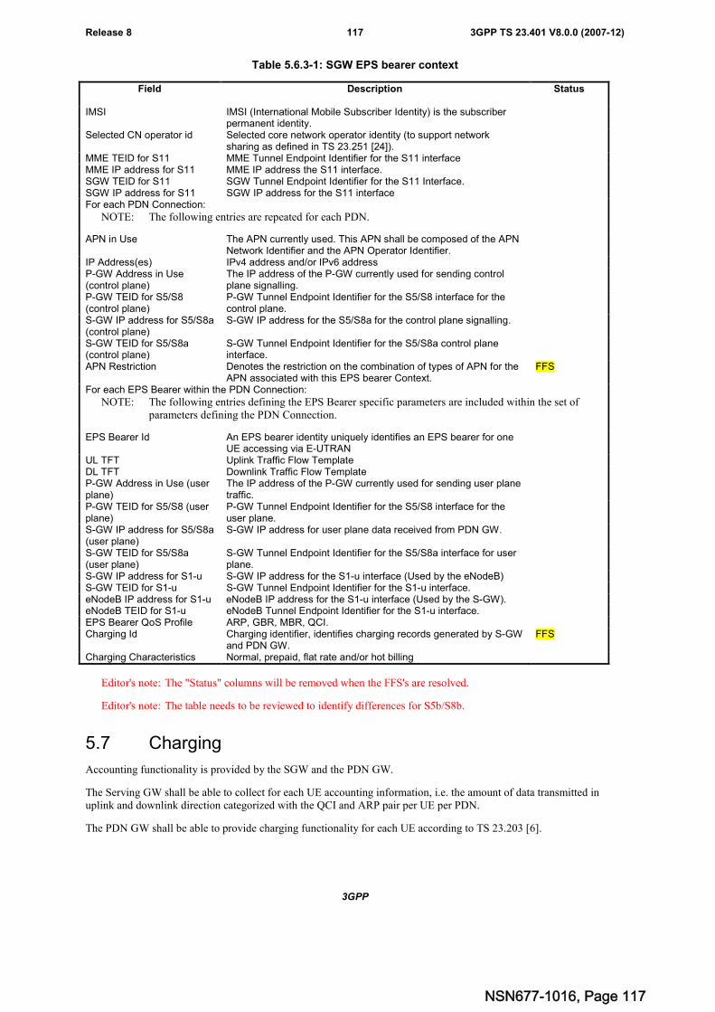
3GPP
3GPP TS 23.401 V8.0.0 (2007-12)117Release 8
Table 5.6.3-1: SGW EPS bearer context
Field Description Status
IMSI IMSI (International Mobile Subscriber Identity) is the subscriberpermanent identity.
Selected CN operator id Selected core network operator identity (to support networksharing as defined in TS 23.251 [24]).
MME TEID for S11 MME Tunnel Endpoint Identifier for the S11 interfaceMME IP address for S11 MME IP address the S11 interface.SGW TEID for S11 SGW Tunnel Endpoint Identifier for the S11 Interface.SGW IP address for S11 SGW IP address for the S11 interfaceFor each PDN Connection:
NOTE: The following entries are repeated for each PDN.
APN in Use The APN currently used. This APN shall be composed of the APNNetwork Identifier and the APN Operator Identifier.
IP Address(es) IPv4 address and/or IPv6 addressP-GW Address in Use(control plane)
The IP address of the P-GW currently used for sending controlplane signalling.
P-GW TEID for S5/S8(control plane)
P-GW Tunnel Endpoint Identifier for the S5/S8 interface for thecontrol plane.
S-GW IP address for S5/S8a(control plane)
S-GW IP address for the S5/S8a for the control plane signalling.
S-GW TEID for S5/S8a(control plane)
S-GW Tunnel Endpoint Identifier for the S5/S8a control planeinterface.
APN Restriction Denotes the restriction on the combination of types of APN for theAPN associated with this EPS bearer Context.
FFS
For each EPS Bearer within the PDN Connection:
NOTE: The following entries defining the EPS Bearer specific parameters are included within the set ofparameters defining the PDN Connection.
EPS Bearer Id An EPS bearer identity uniquely identifies an EPS bearer for oneUE accessing via E-UTRAN
UL TFT Uplink Traffic Flow TemplateDL TFT Downlink Traffic Flow TemplateP-GW Address in Use (userplane)
The IP address of the P-GW currently used for sending user planetraffic.
P-GW TEID for S5/S8 (userplane)
P-GW Tunnel Endpoint Identifier for the S5/S8 interface for theuser plane.
S-GW IP address for S5/S8a(user plane)
S-GW IP address for user plane data received from PDN GW.
S-GW TEID for S5/S8a(user plane)
S-GW Tunnel Endpoint Identifier for the S5/S8a interface for userplane.
S-GW IP address for S1-u S-GW IP address for the S1-u interface (Used by the eNodeB)S-GW TEID for S1-u S-GW Tunnel Endpoint Identifier for the S1-u interface.eNodeB IP address for S1-u eNodeB IP address for the S1-u interface (Used by the S-GW).eNodeB TEID for S1-u eNodeB Tunnel Endpoint Identifier for the S1-u interface.EPS Bearer QoS Profile ARP, GBR, MBR, QCI.Charging Id Charging identifier, identifies charging records generated by S-GW
and PDN GW.FFS
Charging Characteristics Normal, prepaid, flat rate and/or hot billing
Editor's note: The "Status" columns will be removed when the FFS's are resolved.
Editor's note: The table needs to be reviewed to identify differences for S5b/S8b.
5.7 Charging
Accounting functionality is provided by the SGW and the PDN GW.
The Serving GW shall be able to collect for each UE accounting information, i.e. the amount of data transmitted inuplink and downlink direction categorized with the QCI and ARP pair per UE per PDN.
The PDN GW shall be able to provide charging functionality for each UE according to TS 23.203 [6].
NSN677-1016, Page 117
3GPP
3GPP TS 23.401 V8.0.0 (2007-12)118Release 8
A PDN GW without an S7 interface shall be able to support flow based online and offline charging based on localconfiguration and interaction with the Online and Offline Charging Systems.
Editor's note: It is FFS if the PDN GW in addition needs to receive charging characteristics from the ServingGateway or another source.
5.8 MBMS
MBMS is a point-to-multipoint service in which data is transmitted from a single source entity to multiple recipients.Transmitting the same data to multiple recipients allows network resources to be shared.
The Evolved MBMS supports two modes, MBMS Broadcast Mode and MBMS Enhanced Broadcast Mode as definedin TS 23.246 [13].
5.9 Interactions with other services
Editor's Note: This section describes the interactions with other services/features, eg location services,emergency/priority access, possibly terminal configuration, etc.
5.10 Multiple-PDN support
5.10.1 General
This section is related to the support of multiple-PDNs. When a UE attaches to the EPS via E-UTRAN, the principles ofmultiple PDN support defined as below:
- Simultaneous exchange of IP traffic to multiple PDNs is supported in the EPS, when the network policies anduser subscription allow it. For UEs in which applications are not aware of multiple PDN access and the presenceof multiple IP addresses, overlapping address spaces are not supported.
- It shall be possible to support in the EPS simultaneous exchange of IP traffic to multiple PDNs through the useof separate PDN GWs or single PDN GW.
- The EPS also supports an UE-initiated connectivity establishment to separate PDN GWs or single PDN GW inorder to allow parallel access to multiple PDNs.
Editor's Note: The last two bullets should be converted into normative specification wording.
5.10.2 UE requested PDN connectivity
The UE requested PDN connectivity procedure for an E-UTRAN is depicted in figure 5.10.2-1. The procedure allowsthe UE to request for connectivity to a PDN including allocation of a default bearer. In this procedure, the UE isassumed to be in active mode.
NSN677-1016, Page 118
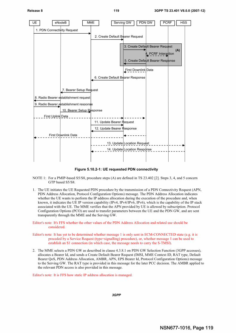
3GPP
3GPP TS 23.401 V8.0.0 (2007-12)119Release 8
1. PDN Connectivity Request
MME Serving GW PCRF HSSPDN GWeNodeBUE
6. Create Default Bearer Response
2. Create Default Bearer Request
7. Bearer Setup Request
First Uplink Data
3. Create Default Bearer Request
5. Create Default Bearer Response
4. PCRF Interaction
9. Radio Bearer establishment response
8. Radio Bearer establishment request
10. Bearer Setup Response
12. Update Bearer Response
11. Update Bearer Request
First Downlink Data
First Downlink Data
13. Update Location Request
14. Update Location Response
(A)
Figure 5.10.2-1: UE requested PDN connectivity
NOTE 1: For a PMIP-based S5/S8, procedure steps (A) are defined in TS 23.402 [2]. Steps 3, 4, and 5 concernGTP based S5/S8.
1. The UE initiates the UE Requested PDN procedure by the transmission of a PDN Connectivity Request (APN,PDN Address Allocation, Protocol Configuration Options) message. The PDN Address Allocation indicateswhether the UE wants to perform the IP address allocation during the execution of the procedure and, whenknown, it indicates the UE IP version capability (IPv4, IPv4/IPv6, IPv6), which is the capability of the IP stackassociated with the UE. The MME verifies that the APN provided by UE is allowed by subscription. ProtocolConfiguration Options (PCO) are used to transfer parameters between the UE and the PDN GW, and are senttransparently through the MME and the Serving GW.
Editor's note: It's FFS whether the other values of the PDN Address Allocation and related use should beconsidered.
Editor's note: It has yet to be determined whether message 1 is only sent in ECM-CONNECTED state (e.g. it ispreceded by a Service Request (type=signalling) procedure), or, whether message 1 can be used toestablish an S1 connection (in which case, the message needs to carry the S-TMSI).
2. The MME selects a PDN GW as described in clause 4.3.8.1 on PDN GW Selection Function (3GPP accesses),allocates a Bearer Id, and sends a Create Default Bearer Request (IMSI, MME Context ID, RAT type, DefaultBearer QoS, PDN Address Allocation, AMBR, APN, EPS Bearer Id, Protocol Configuration Options) messageto the Serving GW. The RAT type is provided in this message for the later PCC decision. The AMBR applied tothe relevant PDN access is also provided in this message.
Editor's note: It is FFS how static IP address allocation is managed.
NSN677-1016, Page 119
3GPP
3GPP TS 23.401 V8.0.0 (2007-12)120Release 8
3. The Serving GW creates a new entry in its EPS Bearer table and sends a Create Default Bearer Request (ServingGW Address for the user plane, Serving GW TEID of the user plane, Serving GW TEID of the control plane,RAT type, Default Bearer QoS, PDN Address Allocation, AMBR, APN, Bearer Id, Protocol ConfigurationOptions) message to the PDN GW. After this step, the Serving GW buffers any downlink packets it may receivefrom the PDN GW until receives the message in step 11 below.
4. The PDN GW may interact with the PCRF to get the default PCC rules for the UE if PCRF is applied in thenetwork. This may optionally lead to the establishment of a number of dedicated bearers following theprocedures defined in clause 5.4.1 in association with the establishment of the default bearer. It is FFS how theestablishment of the default and dedicated bearers is synchronized.
The RAT type is provided to the PCRF by the PDN GW if received by the previous message. If the PDNGW/PCEF is configured to activate predefined PCC rules for the default bearer, the interaction with the PCRF isnot required (e.g. operator may configure to do this) at the moment.
Editor's note: It is FFS which kind of information will be provided by the PCRF.
5. The PDN GW returns a Create Default Bearer Response (PDN GW Address for the user plane, PDN GW TEIDof the user plane, PDN GW TEID of the control plane, PDN Address Information, EPS Bearer Id, ProtocolConfiguration Options) message to the Serving GW. PDN Address Information is included if the PDN GWallocated a PDN address Based on PDN Address Allocation received in the Create Default Bearer Request. PDNAddress Information contains an IPv4 address for IPv4 and/or an IPv6 prefix and an Interface Identifier for IPv6.The PDN GW takes into account the UE IP version capability indicated in the PDN Address Allocation and thepolicies of operator when the PDN GW allocates the PDN Address Information.
6. The Serving GW returns a Create Default Bearer Response (PDN Address Information, Serving GW address forUser Plane, Serving GW TEID for User Plane, Serving GW Context ID, Bearer Id, Protocol ConfigurationOptions) message to the MME. PDN Address Information is included if it was provided by the PDN GW.
7. The MME sends PDN Connectivity Accept (PDN Address Information, EPS Bearer Id) message to the eNodeB.This message is contained in an S1_MME control message Bearer Setup Request (Bearer QoS, PDNConnectivity Accept, S1-TEID, Protocol Configuration Options). This S1 control message includes bearer levelQoS parameters and the AMBR associated with the PDN Address Information, and QoS information needed toset up the radio bearer, as well as the TEID at the Serving GW used for user plane and the address of the ServingGW for user plane. The PDN address information, if assigned by the PDN GW, is included in this message.MME will not send the S1 Bearer Setup Request message until any outstanding S1 Bearer Setup Responsemessage for the same UE has been received or timed out.
8. The eNodeB sends Radio Bearer Establishment Request to the UE and the PDN Connectivity Accept (PDNAddress Information, EPS Bearer Id, Protocol Configuration Options) will be sent along to the UE. The UE shallignore the IPv6 prefix information in PDN Address Information.
NOTE 2: The IP address allocation details are described in the clause 5.3.1 "IP Address Allocation".
9. The UE sends the Radio Bearer Establishment Response (FFS) to the eNodeB.
10. The eNodeB send an S1_MME control message Bearer Setup Response to the MME. The S1 control messageincludes the TEID of the eNodeB and the address of the eNodeB used for downlink traffic on the S1_U referencepoint.
After the PDN Connectivity Accept message and once the UE has obtained a PDN Address Information, the UEcan then send uplink packets towards the eNodeB which will then be tunnelled to the Serving GW and PDNGW.
11. The MME sends an Update Bearer Request (eNodeB address, eNodeB TEID) message to the Serving GW.
12. The Serving GW acknowledges by sending Update Bearer Response to the MME. The Serving GW can thensend its buffered downlink packets.
13. After the MME receives Update Bearer Response in step 13, if an EPS bearer was established, the MME maysend an Update Location Request including the PDN GW address and the APN to the HSS for mobility withnon-3GPP accesses.
14. The HSS stores the PDN GW address and the associated APN, and sends an Update Location Response to theMME.
NSN677-1016, Page 120
3GPP
3GPP TS 23.401 V8.0.0 (2007-12)121Release 8
Editor's Note: The exact message name which is used to transfer the PDN GW address to the HSS is FFS.
NSN677-1016, Page 121
3GPP
3GPP TS 23.401 V8.0.0 (2007-12)122Release 8
Annex A (normative):Agreed requirements, principles and content that should bemoved to other TSs
Editor's Note: This section describes issues and agreements that, prior to approval of this Technical Specification,should be moved to other normative specifications, etc.
A.1 Requirements derived from technical analysisThe local breakout architecture for the EPS/IMS shall satisfy the following design principles, in addition to theprinciples in clause 4.1 of this specification:
- It shall be possible for the UE to connect to one local PDN directly accessible through the VPLMN, to be usede.g. to gain connectivity with the public Internet. The connectivity with the local PDN directly accessiblethrough the VPLMN shall be authorized by the HPLMN, based on operator's policies and customer'ssubscription profile.
- The UE shall be able to simultaneously connect to one PDN directly accessible through the VPLMN, such as thepublic Internet, and to PDNs reachable only from the HPLMN, such as a corporate network. The establishmentof simultaneous connectivity with multiple PDNs shall be authorized by the HPLMN. For security reasons, itshall also be possible for the home operator to decide which of the subscribed PDNs can be accessedsimultaneously by the UE.
- In case of IMS services, the usage of local breakout for the user plane related to a specific IMS session shall beauthorized by the HPLMN. If local breakout is not authorized for a given IMS session, the user plane of thatsession shall be handled in home routed mode.
NOTE 1: the solution designed to address the principles listed above shall allow Rel8 UEs supporting simultaneousaccess to multiple PDNs to communicate with unmodified Rel7 UEs.
NOTE 2: A single application running on the UE shall not be required to send and receive traffic through multiplePDNs.
NSN677-1016, Page 122
3GPP
3GPP TS 23.401 V8.0.0 (2007-12)123Release 8
Annex B (normative):Standardized QCI characteristics
Editor's note: This Section will be moved to become normative text in TS 23.203 Rel-8.
The service level (i.e., per SDF or per SDF aggregate) QoS parameters are QCI, ARP, GBR, and MBR. This sectionspecifies standardized characteristics associated with standardized QCI values.
Each Service Data Flow (SDF) is associated with one and only one QoS Class Identifier (QCI). For the same IP-CANsession multiple SDFs with the same QCI and ARP can be treated as a single traffic aggregate which is referred to as anSDF aggregate. A QCI is a scalar that is used as a reference to node specific parameters that control packet forwardingtreatment (e.g. scheduling weights, admission thresholds, queue management thresholds, link layer protocolconfiguration, etc.), and that have been pre-configured by the operator owning the node (e.g. eNodeB).
Table B-1 Standardized QCI characteristics
<Placeholder for QCI Table >
NOTE 1: A delay of 30 ms for the delay between a PDN GW and a radio base station should be subtracted from agiven PDB to derive the packet delay budget that applies to the radio interface. This delay is the averagebetween the case where the PDN GW is located "close" to the radio base station (roughly 10 ms) and thecase where the PDN GW is located "far" from the radio base station, e.g. in case of roaming with homerouted traffic (the one-way packet delay between Europe and the US west coast is roughly 50 ms). It isexpected that subtracting this average delay of 30 ms from a given PDB will lead to desired end-to-endperformance in most typical cases. Also, note that the PDB defines an upper bound. Actual packet delays– in particular for GBR traffic – should typically be lower than the PDB specified for a QCI as long as theUE has sufficient radio channel quality.
NOTE 2: The rate of non congestion related packet losses that may occur between a radio base station and a PDNGW should be regarded to be negligible. A PLR value specified for a standardized QCI therefore appliescompletely to the radio interface between a UE and radio base station.
The one-to-one mapping of standardized QCI values to standardized characteristics is captured in Table B-1. Thecharacteristics describe the packet forwarding treatment that an SDF / SDF aggregate receives edge-to-edge between theUE and the PDN GW (see Figure B-1) in terms of the following performance characteristics:
1 Resource Type (GBR or Non-GBR),
2 Packet Delay Budget
3 Packet Loss Rate
The standardized characteristics are not signaled on any interface. They should be understood as guidelines for the pre-configuration of node specific parameters for each QCI. The goal of standardizing a QCI with correspondingcharacteristics is to ensure that applications / services mapped to that QCI receive the same minimum level of QoS inmulti-vendor network deployments and in case of roaming. A standardized QCI and corresponding characteristics isindependent of the UE's current access (3GPP or Non-3GPP).
NSN677-1016, Page 123
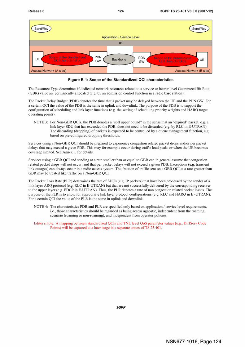
3GPP
3GPP TS 23.401 V8.0.0 (2007-12)124Release 8
Access Network (B side)
IP
Application / Service Level
Send/Rcv
Access Network (A side)
Send/Rcv
UEPDNGW
Scope of the standardizedQCI characteristics UE
PDNGW
Scope of the standardizedQCI characteristicsBackbone
Access Network (B side)
IP
Application / Service Level
Send/Rcv
Access Network (A side)
Send/Rcv
UEPDNGW
Scope of the standardizedQCI characteristicsUE
PDNGW
Scope of the standardizedQCI characteristics UE
PDNGW
Scope of the standardizedQCI characteristics UE
PDNGW
Scope of the standardizedQCI characteristicsBackbone
Figure B-1: Scope of the Standardized QCI characteristics
The Resource Type determines if dedicated network resources related to a service or bearer level Guaranteed Bit Rate(GBR) value are permanently allocated (e.g. by an admission control function in a radio base station).
The Packet Delay Budget (PDB) denotes the time that a packet may be delayed between the UE and the PDN GW. Fora certain QCI the value of the PDB is the same in uplink and downlink. The purpose of the PDB is to support theconfiguration of scheduling and link layer functions (e.g. the setting of scheduling priority weights and HARQ targetoperating points).
NOTE 3: For Non-GBR QCIs, the PDB denotes a "soft upper bound" in the sense that an "expired" packet, e.g. alink layer SDU that has exceeded the PDB, does not need to be discarded (e.g. by RLC in E-UTRAN).The discarding (dropping) of packets is expected to be controlled by a queue management function, e.g.based on pre-configured dropping thresholds.
Services using a Non-GBR QCI should be prepared to experience congestion related packet drops and/or per packetdelays that may exceed a given PDB. This may for example occur during traffic load peaks or when the UE becomescoverage limited. See Annex C for details.
Services using a GBR QCI and sending at a rate smaller than or equal to GBR can in general assume that congestionrelated packet drops will not occur, and that per packet delays will not exceed a given PDB. Exceptions (e.g. transientlink outages) can always occur in a radio access system. The fraction of traffic sent on a GBR QCI at a rate greater thanGBR may be treated like traffic on a Non-GBR QCI.
The Packet Loss Rate (PLR) determines the rate of SDUs (e.g. IP packets) that have been processed by the sender of alink layer ARQ protocol (e.g. RLC in E-UTRAN) but that are not successfully delivered by the corresponding receiverto the upper layer (e.g. PDCP in E-UTRAN). Thus, the PLR denotes a rate of non congestion related packet losses. Thepurpose of the PLR is to allow for appropriate link layer protocol configurations (e.g. RLC and HARQ in E -UTRAN).For a certain QCI the value of the PLR is the same in uplink and downlink.
NOTE 4: The characteristics PDB and PLR are specified only based on application / service level requirements,i.e., those characteristics should be regarded as being access agnostic, independent from the roamingscenario (roaming or non-roaming), and independent from operator policies.
Editor's note: A mapping between standardized QCIs and TNL level QoS parameter values (e.g., DiffServ CodePoints) will be captured at a later stage in a separate annex of TS 23.401.
NSN677-1016, Page 124
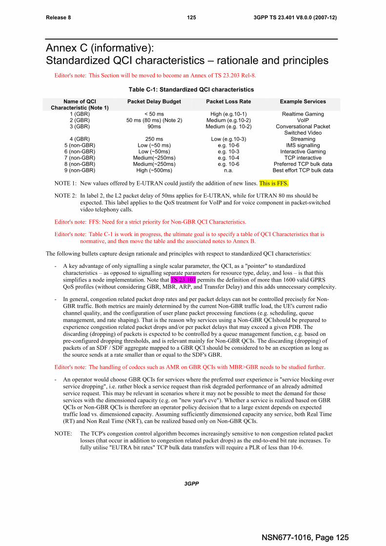
3GPP
3GPP TS 23.401 V8.0.0 (2007-12)125Release 8
Annex C (informative):Standardized QCI characteristics – rationale and principles
Editor's note: This Section will be moved to become an Annex of TS 23.203 Rel-8.
Table C-1: Standardized QCI characteristics
Name of QCICharacteristic (Note 1)
Packet Delay Budget Packet Loss Rate Example Services
1 (GBR) < 50 ms High (e.g.10-1) Realtime Gaming2 (GBR) 50 ms (80 ms) (Note 2) Medium (e.g.10-2) VoIP3 (GBR) 90ms Medium (e.g. 10-2) Conversational Packet
Switched Video4 (GBR) 250 ms Low (e.g.10-3) Streaming
5 (non-GBR) Low (~50 ms) e.g. 10-6 IMS signalling6 (non-GBR) Low (~50ms) e.g. 10-3 Interactive Gaming7 (non-GBR) Medium(~250ms) e.g. 10-4 TCP interactive8 (non-GBR) Medium(~250ms) e.g. 10-6 Preferred TCP bulk data9 (non-GBR) High (~500ms) n.a. Best effort TCP bulk data
NOTE 1: New values offered by E-UTRAN could justify the addition of new lines. This is FFS.
NOTE 2: In label 2, the L2 packet delay of 50ms applies for E-UTRAN, while for UTRAN 80 ms should beexpected. This label applies to the QoS treatment for VoIP and for voice component in packet-switchedvideo telephony calls.
Editor's note: FFS: Need for a strict priority for Non-GBR QCI Characteristics.
Editor's note: Table C-1 is work in progress, the ultimate goal is to specify a table of QCI Characteristics that isnormative, and then move the table and the associated notes to Annex B.
The following bullets capture design rationale and principles with respect to standardized QCI characteristics:
- A key advantage of only signalling a single scalar parameter, the QCI, as a "pointer" to standardizedcharacteristics – as opposed to signalling separate parameters for resource type, delay, and loss – is that thissimplifies a node implementation. Note that TS 23.107 permits the definition of more than 1600 valid GPRSQoS profiles (without considering GBR, MBR, ARP, and Transfer Delay) and this adds unnecessary complexity.
- In general, congestion related packet drop rates and per packet delays can not be controlled precisely for Non-GBR traffic. Both metrics are mainly determined by the current Non-GBR traffic load, the UE's current radiochannel quality, and the configuration of user plane packet processing functions (e.g. scheduling, queuemanagement, and rate shaping). That is the reason why services using a Non-GBR QCIshould be prepared toexperience congestion related packet drops and/or per packet delays that may exceed a given PDB. Thediscarding (dropping) of packets is expected to be controlled by a queue management function, e.g. based onpre-configured dropping thresholds, and is relevant mainly for Non-GBR QCIs. The discarding (dropping) ofpackets of an SDF / SDF aggregate mapped to a GBR QCI should be considered to be an exception as long asthe source sends at a rate smaller than or equal to the SDF's GBR.
Editor's note: The handling of codecs such as AMR on GBR QCIs with MBR>GBR needs to be studied further.
- An operator would choose GBR QCIs for services where the preferred user experience is "service blocking overservice dropping", i.e. rather block a service request than risk degraded performance of an already admittedservice request. This may be relevant in scenarios where it may not be possible to meet the demand for thoseservices with the dimensioned capacity (e.g. on "new year's eve"). Whether a service is realized based on GBRQCIs or Non-GBR QCIs is therefore an operator policy decision that to a large extent depends on expectedtraffic load vs. dimensioned capacity. Assuming sufficiently dimensioned capacity any service, both Real Time(RT) and Non Real Time (NRT), can be realized based only on Non-GBR QCIs.
NOTE: The TCP's congestion control algorithm becomes increasingly sensitive to non congestion related packetlosses (that occur in addition to congestion related packet drops) as the end-to-end bit rate increases. Tofully utilise "EUTRA bit rates" TCP bulk data transfers will require a PLR of less than 10-6.
NSN677-1016, Page 125
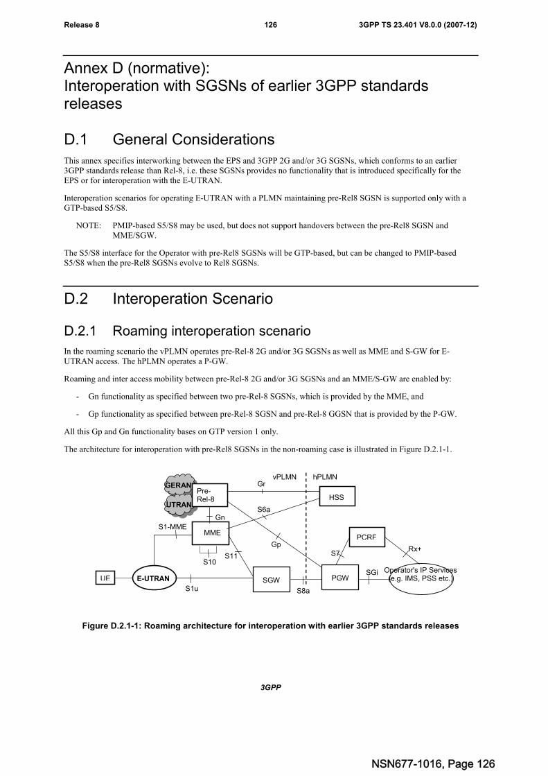
3GPP
3GPP TS 23.401 V8.0.0 (2007-12)126Release 8
Annex D (normative):Interoperation with SGSNs of earlier 3GPP standardsreleases
D.1 General ConsiderationsThis annex specifies interworking between the EPS and 3GPP 2G and/or 3G SGSNs, which conforms to an earlier3GPP standards release than Rel-8, i.e. these SGSNs provides no functionality that is introduced specifically for theEPS or for interoperation with the E-UTRAN.
Interoperation scenarios for operating E-UTRAN with a PLMN maintaining pre-Rel8 SGSN is supported only with aGTP-based S5/S8.
NOTE: PMIP-based S5/S8 may be used, but does not support handovers between the pre-Rel8 SGSN andMME/SGW.
The S5/S8 interface for the Operator with pre-Rel8 SGSNs will be GTP-based, but can be changed to PMIP-basedS5/S8 when the pre-Rel8 SGSNs evolve to Rel8 SGSNs.
D.2 Interoperation Scenario
D.2.1 Roaming interoperation scenario
In the roaming scenario the vPLMN operates pre-Rel-8 2G and/or 3G SGSNs as well as MME and S-GW for E-UTRAN access. The hPLMN operates a P-GW.
Roaming and inter access mobility between pre-Rel-8 2G and/or 3G SGSNs and an MME/S-GW are enabled by:
- Gn functionality as specified between two pre-Rel-8 SGSNs, which is provided by the MME, and
- Gp functionality as specified between pre-Rel-8 SGSN and pre-Rel-8 GGSN that is provided by the P-GW.
All this Gp and Gn functionality bases on GTP version 1 only.
The architecture for interoperation with pre-Rel8 SGSNs in the non-roaming case is illustrated in Figure D.2.1-1.
SGi
Gp
Gn
S1-MME
PCRF
S7
S6a
HSS
S10
UE
GERAN
UTRAN
Pre-Rel-8
E-UTRAN
MME
S11
S8a
SGW PGW
Rx+
GrvPLMN hPLMN
S1u
Operator's IP Services(e.g. IMS, PSS etc.)
Figure D.2.1-1: Roaming architecture for interoperation with earlier 3GPP standards releases
NSN677-1016, Page 126
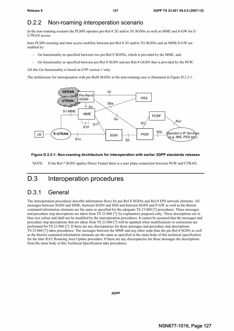
3GPP
3GPP TS 23.401 V8.0.0 (2007-12)127Release 8
D.2.2 Non-roaming interoperation scenario
In the non-roaming scenario the PLMN operates pre-Rel-8 2G and/or 3G SGSNs as well as MME and S-GW for E-UTRAN access.
Intra PLMN roaming and inter access mobility between pre-Rel-8 2G and/or 3G SGSNs and an MME/S-GW areenabled by:
- Gn functionality as specified between two pre-Rel-8 SGSNs, which is provided by the MME, and
- Gn functionality as specified between pre-Rel-8 SGSN and pre-Rel-8 GGSN that is provided by the PGW.
All this Gn functionality is based on GTP version 1 only.
The architecture for interoperation with pre-Rel8 SGSNs in the non-roaming case is illustrated in Figure D.2.2-1.
SGi
Gn
Gn
S1-MME
PCRF
S7
S6a
HSS
S10
UE
GERAN
UTRAN
Pre-Rel-8SGSN
E-UTRAN
MME
S11
S5
SGW PGW Operator's IP Services(e.g. IMS, PSS etc.)
Rx+
Gr
S1u
Figure D.2.2-1: Non-roaming Architecture for interoperation with earlier 3GPP standards releases
NOTE: If the Rel-7 SGSN applies Direct Tunnel there is a user plane connection between PGW and UTRAN.
D.3 Interoperation procedures
D.3.1 General
The interoperation procedures describe information flows for pre-Rel-8 SGSNs and Rel-8 EPS network elements. Allmessages between SGSN and MME, between SGSN and HSS and between SGSN and P-GW as well as the thereincontained information elements are the same as specified for the adequate TS 23.060 [7] procedures. These messagesand procedure step descriptions are taken from TS 23.060 [7] for explanatory purposes only. These descriptions are inblue text colour and shall not be modified by the interoperation procedures. It cannot be assumed that the messages andprocedure step descriptions that are taken from TS 23.060 [7] will be updated when modifications or corrections areperformed for TS 23.060 [7]. If there are any discrepancies for these messages and procedure step descriptionsTS 23.060 [7] takes precedence. The messages between the MME and any other node than the pre-Rel-8 SGSN as wellas the therein contained information elements are the same as specified in the main body of this technical specificationfor the inter RAT Routeing Area Update procedure. If there are any discrepancies for these messages the descriptionsfrom the main body of this Technical Specification take precedence.
NSN677-1016, Page 127
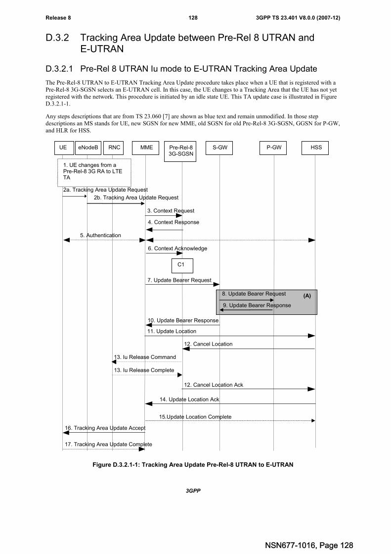
3GPP
3GPP TS 23.401 V8.0.0 (2007-12)128Release 8
D.3.2 Tracking Area Update between Pre-Rel 8 UTRAN andE-UTRAN
D.3.2.1 Pre-Rel 8 UTRAN Iu mode to E-UTRAN Tracking Area Update
The Pre-Rel-8 UTRAN to E-UTRAN Tracking Area Update procedure takes place when a UE that is registered with aPre-Rel-8 3G-SGSN selects an E-UTRAN cell. In this case, the UE changes to a Tracking Area that the UE has not yetregistered with the network. This procedure is initiated by an idle state UE. This TA update case is illustrated in FigureD.3.2.1-1.
Any steps descriptions that are from TS 23.060 [7] are shown as blue text and remain unmodified. In those stepdescriptions an MS stands for UE, new SGSN for new MME, old SGSN for old Pre-Rel-8 3G-SGSN, GGSN for P-GW,and HLR for HSS.
2a. Tracking Area Update Request
11. Update Location
4. Context Response
5. Authentication
16. Tracking Area Update Accept
12. Cancel Location
6. Context Acknowledge
3. Context Request
13. Iu Release Command
13. Iu Release Complete
17. Tracking Area Update Complete
UE eNodeB MME Pre-Rel-83G-SGSN
S-GW P-GW HSS
1. UE changes from aPre-Rel-8 3G RA to LTETA
2b. Tracking Area Update Request
14. Update Location Ack
12. Cancel Location Ack
15.Update Location Complete
7. Update Bearer Request
10. Update Bearer Response
8. Update Bearer Request
9. Update Bearer Response
RNC
(A)
C1
Figure D.3.2.1-1: Tracking Area Update Pre-Rel-8 UTRAN to E-UTRAN
NSN677-1016, Page 128
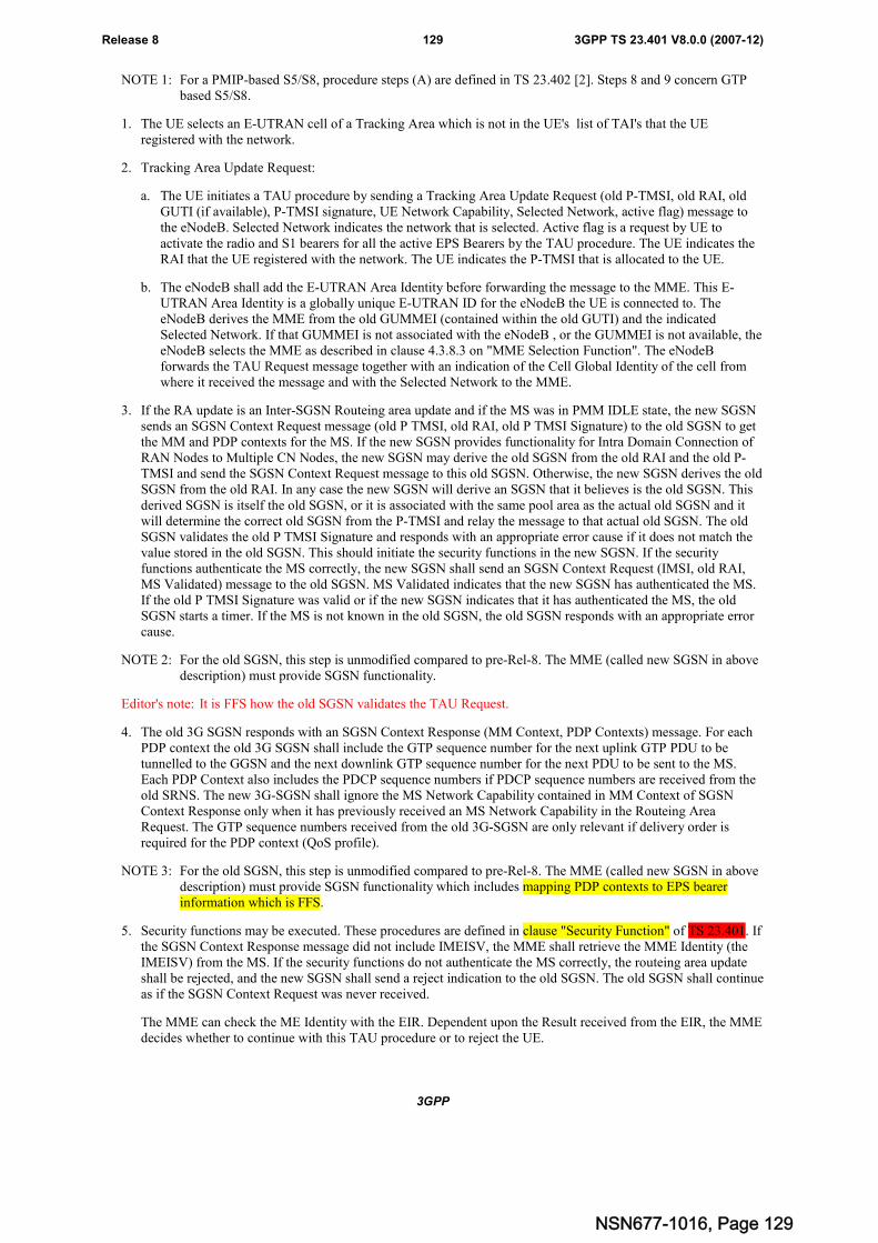
3GPP
3GPP TS 23.401 V8.0.0 (2007-12)129Release 8
NOTE 1: For a PMIP-based S5/S8, procedure steps (A) are defined in TS 23.402 [2]. Steps 8 and 9 concern GTPbased S5/S8.
1. The UE selects an E-UTRAN cell of a Tracking Area which is not in the UE's list of TAI's that the UEregistered with the network.
2. Tracking Area Update Request:
a. The UE initiates a TAU procedure by sending a Tracking Area Update Request (old P-TMSI, old RAI, oldGUTI (if available), P-TMSI signature, UE Network Capability, Selected Network, active flag) message tothe eNodeB. Selected Network indicates the network that is selected. Active flag is a request by UE toactivate the radio and S1 bearers for all the active EPS Bearers by the TAU procedure. The UE indicates theRAI that the UE registered with the network. The UE indicates the P-TMSI that is allocated to the UE.
b. The eNodeB shall add the E-UTRAN Area Identity before forwarding the message to the MME. This E-UTRAN Area Identity is a globally unique E-UTRAN ID for the eNodeB the UE is connected to. TheeNodeB derives the MME from the old GUMMEI (contained within the old GUTI) and the indicatedSelected Network. If that GUMMEI is not associated with the eNodeB , or the GUMMEI is not available, theeNodeB selects the MME as described in clause 4.3.8.3 on "MME Selection Function". The eNodeBforwards the TAU Request message together with an indication of the Cell Global Identity of the cell fromwhere it received the message and with the Selected Network to the MME.
3. If the RA update is an Inter-SGSN Routeing area update and if the MS was in PMM IDLE state, the new SGSNsends an SGSN Context Request message (old P TMSI, old RAI, old P TMSI Signature) to the old SGSN to getthe MM and PDP contexts for the MS. If the new SGSN provides functionality for Intra Domain Connection ofRAN Nodes to Multiple CN Nodes, the new SGSN may derive the old SGSN from the old RAI and the old P-TMSI and send the SGSN Context Request message to this old SGSN. Otherwise, the new SGSN derives the oldSGSN from the old RAI. In any case the new SGSN will derive an SGSN that it believes is the old SGSN. Thisderived SGSN is itself the old SGSN, or it is associated with the same pool area as the actual old SGSN and itwill determine the correct old SGSN from the P-TMSI and relay the message to that actual old SGSN. The oldSGSN validates the old P TMSI Signature and responds with an appropriate error cause if it does not match thevalue stored in the old SGSN. This should initiate the security functions in the new SGSN. If the securityfunctions authenticate the MS correctly, the new SGSN shall send an SGSN Context Request (IMSI, old RAI,MS Validated) message to the old SGSN. MS Validated indicates that the new SGSN has authenticated the MS.If the old P TMSI Signature was valid or if the new SGSN indicates that it has authenticated the MS, the oldSGSN starts a timer. If the MS is not known in the old SGSN, the old SGSN responds with an appropriate errorcause.
NOTE 2: For the old SGSN, this step is unmodified compared to pre-Rel-8. The MME (called new SGSN in abovedescription) must provide SGSN functionality.
Editor's note: It is FFS how the old SGSN validates the TAU Request.
4. The old 3G SGSN responds with an SGSN Context Response (MM Context, PDP Contexts) message. For eachPDP context the old 3G SGSN shall include the GTP sequence number for the next uplink GTP PDU to betunnelled to the GGSN and the next downlink GTP sequence number for the next PDU to be sent to the MS.Each PDP Context also includes the PDCP sequence numbers if PDCP sequence numbers are received from theold SRNS. The new 3G-SGSN shall ignore the MS Network Capability contained in MM Context of SGSNContext Response only when it has previously received an MS Network Capability in the Routeing AreaRequest. The GTP sequence numbers received from the old 3G-SGSN are only relevant if delivery order isrequired for the PDP context (QoS profile).
NOTE 3: For the old SGSN, this step is unmodified compared to pre-Rel-8. The MME (called new SGSN in abovedescription) must provide SGSN functionality which includes mapping PDP contexts to EPS bearerinformation which is FFS.
5. Security functions may be executed. These procedures are defined in clause "Security Function" of TS 23.401. Ifthe SGSN Context Response message did not include IMEISV, the MME shall retrieve the MME Identity (theIMEISV) from the MS. If the security functions do not authenticate the MS correctly, the routeing area updateshall be rejected, and the new SGSN shall send a reject indication to the old SGSN. The old SGSN shall continueas if the SGSN Context Request was never received.
The MME can check the ME Identity with the EIR. Dependent upon the Result received from the EIR, the MMEdecides whether to continue with this TAU procedure or to reject the UE.
NSN677-1016, Page 129
3GPP
3GPP TS 23.401 V8.0.0 (2007-12)130Release 8
6. If the RA update is an Inter-SGSN Routeing area update, the new SGSN sends an SGSN Context Acknowledgemessage to the old SGSN. The old SGSN marks in its context that the MSC/VLR association and theinformation in the GGSNs and the HLR are invalid. This triggers the MSC/VLR, the GGSNs, and the HLR to beupdated if the MS initiates a routeing area update procedure back to the old SGSN before completing theongoing routeing area update procedure.
NOTE 4: For the old SGSN, this step is unmodified compared to pre-Rel-8. Handling within the MME (called newSGSN in above description) may need further alignment with the Rel-8 inter RAT RAU.
7. The MME sends an Update Bearer Request (new MME address and TEID, QoS Negotiated, Serving networkidentity, ME Identity) message to the selected new Serving GW. The PDN GW address is indicated in the bearercontexts.
Editor's note: It is FFS how to handle the case when the UE has no PDP contexts.
8. The Serving GW informs the PDN GW(s) the change of for example the RAT type that e.g. can be used forcharging, by sending the message Update Bearer Request (Serving GW Address and TEID, RAT type, MEIdentity, etc.) to the PDN GW(s) concerned.
9. The PDN GW updates its context field to allow DL PDUs to be routed to the correct Serving GW. PDN GWreturns an Update Bearer Response (PDN GW address and TEID, etc.) to the Serving GW.
10. The Serving GW updates its bearer context. This allows the Serving GW to route Bearer PDUs to the PDN GWwhen received from eNodeB.
The Serving GW returns an Update Bearer Response (Serving GW address and TEID, PDN GW Address andTEID) message to the new MME.
11. The new MME informs the HSS of the change of SGSN to MME by sending an Update Location (MME Id,IMSI, ME Identity) message to the HSS. The ME Identity is included if, in step 5, the SGSN Context Responsedid not contain the IMEISV.
12. If the RA update is an Inter-SGSN RA Update, the HLR sends Cancel Location (IMSI, Cancellation Type) to theold SGSN with Cancellation Type set to Update Procedure. If the timer described in step 3 is not running, the oldSGSN removes the MM context. Otherwise, the contexts are removed only when the timer expires. It alsoensures that the MM context is kept in the old SGSN in case the MS initiates another inter SGSN routeing areaupdate before completing the ongoing routeing area update to the new SGSN. The old SGSN acknowledges withCancel Location Ack (IMSI).
NOTE 5: This step is unmodified compared to pre-Rel-8.
13. On receipt of Cancel Location, if the MS is PMM CONNECTED in the old 3G SGSN, the old 3G SGSN sendsan Iu Release Command message to the old SRNC. When the data-forwarding timer has expired, the SRNSresponds with an Iu Release Complete message.
NOTE 6: This step is unmodified compared to pre-Rel-8.
14. The HSS acknowledges the Update Location by returning an Update Location Ack (IMSI) message to the newMME after the cancelling of the old SGSN context is finished. If the Update Location is rejected by the HSS, theMME rejects the TAU Request from the UE with an appropriate cause sent in the TAU Reject message to theUE.
The HSS includes Subscription Data in the Update Location Ack message to the new MME.
Editor's note: It is FFS if subscriber data is included in this step, or it is sent in an Insert Subscriber Data message.
15. The new MME acknowledges the received subscription data with an Update Location Complete message to theHSS.
Editor's note: It is FFS if this step is needed.
16. The MME validates the UE's presence in the new TA, after it has received valid and updated subscription data. Ifdue to regional subscription restrictions or access restrictions the UE is not allowed to attach in the TA, theMME rejects the Attach Request with an appropriate cause sent in the TAU Reject message to the UE.
NSN677-1016, Page 130
3GPP
3GPP TS 23.401 V8.0.0 (2007-12)131Release 8
If validation is successful the MME responds to the UE with a Tracking Area Update Accept (GUTI, TAI-list)message. Restriction list shall be sent to eNodeB as eNodeB handles the roaming restrictions and accessrestrictions in the Intra E-UTRAN case. If the "active flag" is set in the TAU Request message the user planesetup procedure can be activated in conjunction with the TAU Accept message. The procedure is described indetail in TS 36.300 [5]. The message sequence should be the same as for the UE triggered Service Requestprocedure specified in clause 5.3.4.1 from the step when MME establish the bearers(s).
17. If the GUTI was included in the TAU Accept message, the UE acknowledges the message by returning aTracking Area Update Complete message to the MME.
The CAMEL procedure calls shall be performed, see referenced procedures in TS 23.078 [29]:
C1) CAMEL_GPRS_PDP_Context_Disconnection, CAMEL_GPRS_Detach and CAMEL_PS_Notification.
They are called in the following order:
- The CAMEL_GPRS_PDP_Context_Disconnection procedure is called several times: once per PDP context.The procedure returns as result "Continue".
- Then the CAMEL_GPRS_Detach procedure is called once. The procedure returns as result "Continue".
- Then the CAMEL_PS_Notification procedure is called once. The procedure returns as result "Continue".
NOTE 7: This step is unmodified compared to pre-Rel-8.
NOTE 8: CAMEL procedure calls C2 and C3 were omitted intentionally from the above Tracking Area UpdatePre-Rel-8 UTRAN to E-UTRAN procedure since EPS does not support CAMEL procedure calls.
NOTE 9: The new MME may initiate RAB establishment after execution of the security functions (step 5), or waituntil completion of the TA update procedure. For the UE, RAB establishment may occur anytime afterthe TA update request is sent (step 2).
In the case of a rejected tracking area update operation, due to regional subscription, roaming restrictions, or accessrestrictions (see TS 23.221 [27] and TS 23.008 [28]) the new MME shall not construct a bearer context. A reject shallbe returned to the UE with an appropriate cause. The UE shall not re-attempt a tracking area update to that TA. The TAIvalue shall be deleted when the UE is powered up. It is FFS whether the TAI value being deleted until power up asspecified both here and in TS 23.060 [7] is correct.
If the new MME is unable to update the bearer context in one or more P-GWs, the new MME shall deactivate thecorresponding bearer contexts as described in subclause "MME Initiated Dedicated Bearer Deactivation Procedure".This shall not cause the MME to reject the tracking area update.
The PDP Contexts shall be sent from old SGSN to new SGSN (MME) in a prioritized order, i.e. the most importantPDP Context first in the SGSN Context Response message. (The prioritization method is implementation dependent,but should be based on the current activity).
The new MME shall determine the Maximum APN restriction based on the received APN Restriction of each bearercontext from the P-GW and then store the new Maximum APN restriction value.
If the new MME is unable to support the same number of active bearer contexts as received from old SGSN, the newMME should use the prioritisation sent by old SGSN as input when deciding which bearer contexts to maintain activeand which ones to delete. In any case, the new MME shall first update all contexts in one or more P-GWs and thendeactivate the context(s) that it cannot maintain as described in subclause "MME Initiated Dedicated BearerDeactivation Procedure". This shall not cause the MME to reject the tracking area update.
NOTE 10:In case MS (UE) was in PMM-CONNECTED state the PDP Contexts are sent already in the ForwardRelocation Request message as described in subclause "Serving RNS relocation procedures" ofTS 23.060 [7].
If the tracking area update procedure fails a maximum allowable number of times, or if the MME returns a TrackingArea Update Reject (Cause) message, the UE shall enter EMM-DEREGISTERED state.
If the Update Location Ack message indicates a reject, this should be indicated to the UE, and the UE shall not accessnon-PS services until a successful location update is performed.
NSN677-1016, Page 131
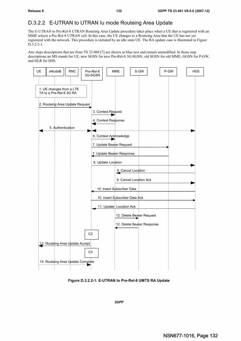
3GPP
3GPP TS 23.401 V8.0.0 (2007-12)132Release 8
D.3.2.2 E-UTRAN to UTRAN Iu mode Routeing Area Update
The E-UTRAN to Pre-Rel-8 UTRAN Routeing Area Update procedure takes place when a UE that is registered with anMME selects a Pre-Rel-8 UTRAN cell. In this case, the UE changes to a Routeing Area that the UE has not yetregistered with the network. This procedure is initiated by an idle state UE. The RA update case is illustrated in FigureD.3.2.2-1.
Any steps descriptions that are from TS 23.060 [7] are shown as blue text and remain unmodified. In those stepdescriptions an MS stands for UE, new SGSN for new Pre-Rel-8 3G-SGSN, old SGSN for old MME, GGSN for P-GW,and HLR for HSS.
2. Routeing Area Update Request
8. Update Location
11. Update Location Ack
4. Context Response
5. Authentication
13. Routeing Area Update Accept
9. Cancel Location
9. Cancel Location Ack
6. Context Acknowledge
3. Context Request
14. Routeing Area Update Complete
UE eNodeB Pre-Rel-83G-SGSN
MME S-GW P-GW HSS
1. UE changes from a LTETA to a Pre-Rel-8 3G RA
7. Update Bearer Request
7. Update Bearer Response
RNC
12. Delete Bearer Request
12. Delete Bearer Response
10. Insert Subscriber Data
10. Insert Subscriber Data Ack
C2
C3
Figure D.3.2.2-1: E-UTRAN to Pre-Rel-8 UMTS RA Update
NSN677-1016, Page 132
3GPP
3GPP TS 23.401 V8.0.0 (2007-12)133Release 8
1. The UE selects a Pre-Rel-8 UTRAN cell. This cell is in a Routeing Area that is not yet registered with thenetwork. The UE indicates the GUMMEI and the stored M-TMSI is placed in the P-TMSI field. (This is FFSpending conclusion on the mapping of MMEC to the P-TMSI field and mapping of part of the M-TMSI to the P-TMSI signature field). The new SGSN uses the GUMMEI to derive the old MME (as if it were an SGSN) in thefollowing step(s).
2. The RRC connection is established, if not already done. The MS sends a Routeing Area Update Request message(P-TMSI, old RAI, old P-TMSI Signature, Update Type, follow on request, Classmark, DRX Parameters, MSNetwork Capability) to the new SGSN. The MS shall set a follow-on request if there is pending uplink traffic(signalling or user data). The SGSN may use, as an implementation option, the follow-on request indication torelease or keep the Iu connection after the completion of the RA update procedure. Update Type shall indicate:
- RA Update if the RA Update is triggered by a change of RA;
- Periodic RA Update if the RA update is triggered by the expiry of the Periodic RA Update timer;
- Combined RA / LA Update if the MS is also IMSI-attached and the LA update shall be performed in networkoperation mode I (see clause "Interactions Between SGSN and MSC/VLR" of TS 23.060 [7]); or
- Combined RA / LA Update with IMSI attach requested if the MS wants to perform an IMSI attach innetwork operation mode I.
The SRNC shall add the Routeing Area Identity before forwarding the message to the 3G-SGSN. This RAidentity corresponds to the RAI in the MM system information sent by the SRNC to the MS. Classmark isdescribed in clause "MS Network Capability" of TS 23.060 [7]. DRX Parameters indicates whether or not theMS uses discontinuous reception and the DRX cycle length.
NOTE 1: Sending the Routeing Area Update Request message to the SGSN triggers the establishment of asignalling connection between RAN and SGSN for the concerned MS.
NOTE 2: For the new SGSN, this step is unmodified compared to pre-Rel-8. The MME (called old SGSN in abovedescription) must provide SGSN functionality.
3. If the RA update is an Inter-SGSN Routeing area update and if the MS was in PMM IDLE state, the new SGSNsends an SGSN Context Request message (old P TMSI, old RAI, old P TMSI Signature) to the old SGSN to getthe MM and PDP contexts for the MS. If the new SGSN provides functionality for Intra Domain Connection ofRAN Nodes to Multiple CN Nodes, the new SGSN may derive the old SGSN from the old RAI and the old P-TMSI and send the SGSN Context Request message to this old SGSN. Otherwise, the new SGSN derives the oldSGSN from the old RAI. In any case the new SGSN will derive an SGSN that it believes is the old SGSN. Thisderived SGSN is itself the old SGSN, or it is associated with the same pool area as the actual old SGSN and itwill determine the correct old SGSN from the P-TMSI and relay the message to that actual old SGSN. The oldSGSN validates the old P TMSI Signature and responds with an appropriate error cause if it does not match thevalue stored in the old SGSN. This should initiate the security functions in the new SGSN. If the securityfunctions authenticate the MS correctly, the new SGSN shall send an SGSN Context Request (IMSI, old RAI,MS Validated) message to the old SGSN. MS Validated indicates that the new SGSN has authenticated the MS.If the old P TMSI Signature was valid or if the new SGSN indicates that it has authenticated the MS, the oldSGSN starts a timer. If the MS is not known in the old SGSN, the old SGSN responds with an appropriate errorcause.
NOTE 3: For the new SGSN, this step is unmodified compared to pre-Rel-8. The MME (called old SGSN in abovedescription) must provide SGSN functionality.
4. The old 3G SGSN responds with an SGSN Context Response (MM Context, PDP Contexts) message. For eachPDP context the old 3G SGSN shall include the GTP sequence number for the next uplink GTP PDU to betunnelled to the GGSN and the next downlink GTP sequence number for the next PDU to be sent to the MS.Each PDP Context also includes the PDCP sequence numbers if PDCP sequence numbers are received from theold SRNS. The new 3G-SGSN shall ignore the MS Network Capability contained in MM Context of SGSNContext Response only when it has previously received an MS Network Capability in the Routeing AreaRequest. The GTP sequence numbers received from the old 3G-SGSN are only relevant if delivery order isrequired for the PDP context (QoS profile).
NOTE 4: For the new SGSN, this step is unmodified compared to pre-Rel-8. The MME (called old SGSN in abovedescription) must provide SGSN functionality which includes mapping EPS bearer information to PDPcontexts which is FFS.
NSN677-1016, Page 133
3GPP
3GPP TS 23.401 V8.0.0 (2007-12)134Release 8
5. Security functions may be executed. These procedures are defined in clause "Security Function" ofTS 23.060 [7]. If the SGSN Context Response message did not include IMEISV and ADD is supported, theSGSN retrieves the IMEISV from the MS. If the security functions do not authenticate the MS correctly, therouteing area update shall be rejected, and the new SGSN shall send a reject indication to the old SGSN. The oldSGSN shall continue as if the SGSN Context Request was never received.
NOTE 5: This step is unmodified compared to pre-Rel-8.
6. The new SGSN sends an SGSN Context Acknowledge message to the old SGSN. The old MME marks in itscontext that the information in the GWs and the HSS are invalid. This ensures that the old MME updates theGWs and the HSS if the UE initiates a TAU procedure back to the old MME before completing the ongoingTAU procedure.
NOTE 6: For the new SGSN, this step is unmodified compared to pre-Rel-8. Handling within the MME (called oldSGSN in above description) may need further alignment with the Rel-8 inter RAT RAU.
7. If the RA update is an Inter-SGSN RA Update and if the MS was not in PMM-CONNECTED state in the new3G-SGSN, the new SGSN sends Update PDP Context Request (new SGSN Address, QoS Negotiated, TunnelEndpoint Identifier, serving network identity, CGI/SAI, RAT type, CGI/SAI/RAI change support indication,NRSN) to the GGSNs concerned. The SGSN shall send the serving network identity to the GGSN. NRSNindicates SGSN support of the network requested bearer control. The GGSNs update their PDP context fieldsand return an Update PDP Context Response (Tunnel Endpoint Identifier, Prohibit Payload Compression, APNRestriction, CGI/SAI/RAI change report required, BCM). The Prohibit Payload Compression indicates that theSGSN should negotiate no data compression for this PDP context. Note: If the RA update is an Inter-SGSNrouteing area update initiated by an MS in PMM CONNECTED state in the new 3G-SGSN, the Update PDPContext Request message is sent as described in subclause "Serving RNS Relocation Procedures" ofTS 23.060 [7].
NOTE 7: For the new SGSN, this step is unmodified compared to pre-Rel-8. The P-GWs (called GGSNs in abovedescription) must provide GGSN functionality.
8. If the RA update is an Inter-SGSN RA Update, the new SGSN informs the HLR of the change of SGSN bysending Update Location (SGSN Number, SGSN Address, IMSI, IMEISV) to the HLR. IMEISV is sent if theADD function is supported.
NOTE 8: This step is unmodified compared to pre-Rel-8.
9. The HSS sends a Cancel Location (IMSI, Cancellation Type) message to the old MME with the CancellationType set to Update Procedure.
If the timer started in step 3 is not running, the old MME removes the MM context. Otherwise, the contexts areremoved when the timer expires. It also ensures that the MM context is kept in the old MME for the case the UEinitiates another TAU procedure before completing the ongoing TAU procedure to the new SGSN. The oldMME acknowledges with a Cancel Location Ack (IMSI) message.
10. If the RA update is an inter-SGSN RA Update, the HLR sends Insert Subscriber Data (IMSI, subscription data)to the new SGSN. The new SGSN validates the MS's presence in the (new) RA. If due to regional subscriptionrestrictions or access restrictions the MS is not allowed to be attached in the RA, the SGSN rejects the RouteingArea Update Request with an appropriate cause, and may return an Insert Subscriber Data Ack (IMSI, SGSNArea Restricted) message to the HLR. If the network supports the MOCN configuration for network sharing, theSGSN may, if the MS is not a 'Network Sharing Supporting MS', in this case decide to initiate redirection bysending a Reroute Command to the RNS, as described in TS 23.251 [24] instead of rejecting the Routeing AreaUpdate Request. If all checks are successful, the SGSN constructs an MM context for the MS and returns anInsert Subscriber Data Ack (IMSI) message to the HLR.
NOTE 9: This step is unmodified compared to pre-Rel-8.
11. If the RA update is an Inter-SGSN RA Update, the HLR acknowledges the Update Location by sending UpdateLocation Ack (IMSI) to the new SGSN.
NOTE 10:This step is unmodified compared to pre-Rel-8.
12. When the old MME removes the MM context, the old MME deletes the EPS bearer resources by sending DeleteBearer Request (TEID, cause) messages to the Serving GW. Cause indicates to the old Serving GW that the oldServing GW shall not initiate a delete procedure towards the PDN GW.
NSN677-1016, Page 134
3GPP
3GPP TS 23.401 V8.0.0 (2007-12)135Release 8
13. The new SGSN validates the MS's presence in the new RA. If due to roaming restrictions or access restrictionsthe MS is not allowed to be attached in the RA, or if subscription checking fails, the SGSN rejects the routeingarea update with an appropriate cause. If the network supports the MOCN configuration for network sharing, theSGSN may, if the MS is not a 'Network Sharing Supporting MS', in this case decide to initiate redirection bysending a Reroute Command to the RNS, as described in TS 23.251 [24] instead of rejecting the routeing areaupdate. If all checks are successful, the new SGSN establishes MM context for the MS. The new SGSN respondsto the MS with Routeing Area Update Accept (P TMSI, VLR TMSI, P TMSI Signature).
NOTE 11:This step is unmodified compared to pre-Rel-8.
The CAMEL procedure calls shall be performed, see referenced procedures in TS 23.078 [29]:
NOTE 12:The C1 CAMEL procedure call was omitted intentionally from the above E-UTRAN to Pre-Rel-8 UMTSRA Update procedure since EPS does not support CAMEL procedure calls.
C2) CAMEL_GPRS_Routeing_Area_Update_Session and CAMEL_PS_Notification.
They are called in the following order:
- The CAMEL_GPRS_Routeing_Area_Update_Session procedure is called. The procedure returns as result"Continue".
- Then the CAMEL_PS_Notification procedure is called. The procedure returns as result "Continue".
NOTE 13:This step is unmodified compared to pre-Rel-8.
C3) CAMEL_GPRS_Routeing_Area_Update_Context.
This procedure is called several times: once per PDP context. It returns as result "Continue".
NOTE 14:This step is unmodified compared to pre-Rel-8.
NOTE 15:The new SGSN may initiate RAB establishment after execution of the security functions (step 5), or waituntil completion of the RA update procedure. For the MS, RAB establishment may occur anytime afterthe RA update request is sent (step 2).
In the case of a rejected routeing area update operation, due to regional subscription, roaming restrictions, or accessrestrictions (see TS 23.221 [27] and TS 23.008 [28]) the new SGSN shall not construct an MM context. A reject shallbe returned to the MS with an appropriate cause. The MS shall not re-attempt a routeing area update to that RA. TheRAI value shall be deleted when the MS is powered up. It is FFS whether the RAI value being deleted until power up asspecified both here and in TS 23.060 [7] is correct. If the network supports the MOCN configuration for networksharing, the SGSN may, if the MS is not a 'Network Sharing Supporting MS', in this case decide to initiate redirectionby sending a Reroute Command to the RNS, as described in TS 23.251 [24] instead of rejecting the routeing areaupdate.
If the new SGSN is unable to update the PDP context in one or more GGSNs, the new SGSN shall deactivate thecorresponding PDP contexts as described in subclause "SGSN-initiated PDP Context Deactivation Procedure" ofTS 23.060 [7]. This shall not cause the SGSN to reject the routeing area update.
The PDP Contexts shall be sent from old to new SGSN in a prioritized order, i.e. the most important PDP Context firstin the SGSN Context Response message. (The prioritization method is implementation dependent, but should be basedon the current activity).
The new SGSN shall determine the Maximum APN restriction based on the received APN Restriction of each PDPcontext from the GGSN and then store the new Maximum APN restriction value.
If the new SGSN is unable to support the same number of active PDP contexts as received from old SGSN, the newSGSN should use the prioritisation sent by old SGSN as input when deciding which PDP contexts to maintain activeand which ones to delete. In any case, the new SGSN shall first update all contexts in one or more GGSNs and thendeactivate the context(s) that it cannot maintain as described in subclause "SGSN-initiated PDP Context DeactivationProcedure" of TS 23.060 [7]. This shall not cause the SGSN to reject the routeing area update.
NOTE 16:In case MS was in PMM-CONNECTED state the PDP Contexts are sent already in the ForwardRelocation Request message as described in subclause "Serving RNS relocation procedures" ofTS 23.060 [7].
NSN677-1016, Page 135
3GPP
3GPP TS 23.401 V8.0.0 (2007-12)136Release 8
If the routeing area update procedure fails a maximum allowable number of times, or if the SGSN returns a RouteingArea Update Reject (Cause) message, the MS shall enter PMM-DETACHED state.
If the Location Update Accept message indicates a reject, this should be indicated to the MS, and the MS shall notaccess non-PS services until a successful location update is performed.
D.3.3 MME to 3G SGSN handover and SRNS relocationprocedure
The MME to 3G SGSN Combined Hard Handover and SRNS Relocation procedure is illustrated in Figure D.3.3-1.
Any steps descriptions that are from TS 23.060 [7] are shown as blue text and remain unmodified. In those stepdescriptions an MS stands for UE, old SGSN for old MME and GGSN for PGW.
The same procedure applies for Rel-8 SGSN to pre-Rel-8 SGSN Combined Hard Handover and SRNS Relocationprocedure. In this case the old MME is an old Rel-8 SGSN.
The procedure between E-UTRAN eNodeB and UE, and between E-UTRAN eNodeB and MME are copied fromTS 23.401 unmodified.
Direct forwarding of payload PDUs is assumed in the scenarios below. The indirect forwarding is FFS for pre-Rel-83GPP IRAT handovers.
NSN677-1016, Page 136
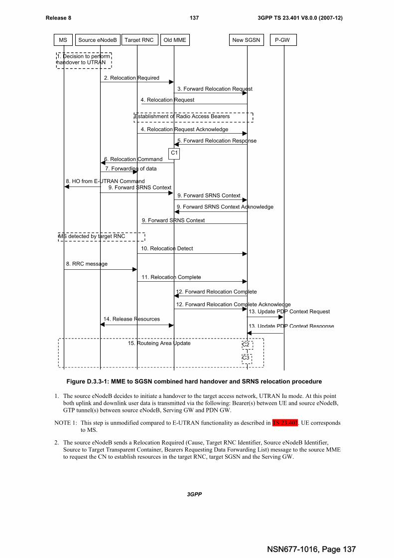
3GPP
3GPP TS 23.401 V8.0.0 (2007-12)137Release 8
Target RNCSource eNodeB Old MME New SGSN P-GW
3. Forward Relocation Request
4. Relocation Request
2. Relocation Required
6. Relocation Command
5. Forward Relocation Response
4. Relocation Request Acknowledge
10. Relocation Detect
MS
9. Forward SRNS Context
9. Forward SRNS Context
9. Forward SRNS Context
8. RRC message
1. Decision to performhandover to UTRAN
MS detected by target RNC
Establishment of Radio Access Bearers
C1
7. Forwarding of data
9. Forward SRNS Context Acknowledge
11. Relocation Complete
12. Forward Relocation Complete
15. Routeing Area Update
13. Update PDP Context Request
14. Release Resources
13. Update PDP Context Response
12. Forward Relocation Complete Acknowledge
C3
C2
8. HO from E-UTRAN Command
Figure D.3.3-1: MME to SGSN combined hard handover and SRNS relocation procedure
1. The source eNodeB decides to initiate a handover to the target access network, UTRAN Iu mode. At this pointboth uplink and downlink user data is transmitted via the following: Bearer(s) between UE and source eNodeB,GTP tunnel(s) between source eNodeB, Serving GW and PDN GW.
NOTE 1: This step is unmodified compared to E-UTRAN functionality as described in TS 23.401. UE correspondsto MS.
2. The source eNodeB sends a Relocation Required (Cause, Target RNC Identifier, Source eNodeB Identifier,Source to Target Transparent Container, Bearers Requesting Data Forwarding List) message to the source MMEto request the CN to establish resources in the target RNC, target SGSN and the Serving GW.
NSN677-1016, Page 137
3GPP
3GPP TS 23.401 V8.0.0 (2007-12)138Release 8
Bearers Requesting Data Forwarding List contains that list of bearers for which the source eNodeB decided thatdata forwarding (direct) is necessary.
NOTE 2: The possibility for indirect forwarding of payload PDUs is omitted in the step above. Otherwise the stepis unmodified compared to E-UTRAN functionality as described in TS 23.401.
3. The old MME sends a Forward Relocation Request message (IMSI, Tunnel Endpoint Identifier Signalling, MMContext, PDP Context, Target Identification, RAN Transparent Container, RANAP Cause, GCSI) to the newSGSN. For relocation to an area where Intra Domain Connection of RAN Nodes to Multiple CN Nodes is used,the old MME may have multiple new SGSNs for each relocation target in a pool area, in which case the oldMME will select one of them to become the new SGSN, as specified in TS 23.236 [30]. PDP context containsGGSN Address for User Plane and Uplink TEID for Data (to this GGSN Address and Uplink TEID for Data, theold SGSN and the new SGSN send uplink packets). At the same time a timer is started on the MM and PDPcontexts in the old MME (see Routeing Area Update procedure in subclause "Location Management Procedures(Iu mode)"). The old SGSN 'sets' the GCSI flag if the MM context contains GPRS CAMEL SubscriptionInformation.
NOTE 3: The GGSN user plane address and uplink TEID are the old P-GW user plane address and TEID. TheMME maps the EPS bearer parameters to PDP contexts.
4. The new SGSN sends a Relocation Request message (Permanent NAS UE Identity, Cause, CN DomainIndicator, Source RNC To Target RNC Transparent Container, RAB To Be Setup) to the target RNC. For eachRAB requested to be established, RABs To Be Setup shall contain information such as RAB ID, RABparameters, Transport Layer Address, and Iu Transport Association. SGSN shall not establish RABs for PDPcontexts with maximum bitrate for uplink and downlink of 0 kbit/s. The list of RABs requested by the newSGSN may differ from list of RABs established in the Source RNC contained in the Source-RNC to target RNCtransparent container. The target RNC should not establish the RABs (as identified from the Source-RNC totarget RNC transparent container) that did not exist in the source RNC prior to the relocation. The RAB IDinformation element contains the NSAPI value, and the RAB parameters information element gives the QoSprofile. The Transport Layer Address is the SGSN Address for user data, and the Iu Transport Associationcorresponds to the uplink Tunnel Endpoint Identifier Data. The new SGSN may decide to establish DirectTunnel unless it has received a 'set' GCSI flag from the old SGSN. If the new SGSN decides to establish DirectTunnel, it provides to the target RNC the GGSN's Address for User Plane and TEID for Uplink data.
After all the necessary resources for accepted RABs including the Iu user plane are successfully allocated, thetarget RNC shall send the Relocation Request Acknowledge message (Target RNC To Source RNC TransparentContainer, RABs Setup, RABs Failed To Setup) to the new SGSN. Each RAB to be setup is defined by aTransport Layer Address, which is the target RNC Address for user data, and the Iu Transport Association,which corresponds to the downlink Tunnel Endpoint Identifier for user data. The transparent container containsall radio-related information that the MS needs for the handover, i.e. a complete RRC message (e.g., PhysicalChannel Reconfiguration in UTRAN case, or Handover From UTRAN, or Handover Command in GERAN Iumode case) to be sent transparently via CN and source SRNC to the MS. For each RAB to be set up, the targetRNC may receive simultaneously downlink user packets both from the source SRNC and from the new SGSN.
NOTE 4: This step for the new SGSN is unmodified compared to pre-Rel-8. If the new SGSN decides to establishDirect Tunnel, it provides to the target RNC the PGW Address for User Plane and TEID for Uplink data.The UE acts as the MS; the old eNodeB acts as the source SRNC. The details of the transparent containerare FFS.
5. When resources for the transmission of user data between target RNC and new SGSN have been allocated andthe new SGSN is ready for relocation of SRNS, the Forward Relocation Response (Cause, RAN TransparentContainer, RANAP Cause, Target-RNC Information) message is sent from the new SGSN to the old SGSN. Thismessage indicates that the target RNC is ready to receive from source SRNC the forwarded downlink PDUs, i.e.,the relocation resource allocation procedure is terminated successfully. RAN transparent container and RANAPCause are information from the target RNC to be forwarded to the source SRNC. The Target RNC Information,one information element for each RAB to be set up, contains the RNC Tunnel Endpoint Identifier and RNC IPaddress for data forwarding from the source SRNC to the target RNC. The Forward Relocation Responsemessage is applicable only in case of inter-SGSN SRNS relocation.
NOTE 5: This step is unmodified compared to pre-Rel-8. The old MME acts as the old SGSN, and the sourceeNodeB as the source SRNC.
6. The source MME completes the preparation phase towards source eNodeB by sending the message RelocationCommand (Target to Source Transparent Container, Bearers Subject to Data Forwarding List). "Bearers Subject
NSN677-1016, Page 138
3GPP
3GPP TS 23.401 V8.0.0 (2007-12)139Release 8
to Data forwarding list" may be included in the message and it shall be a list of 'Address(es) and TEID(s) foruser traffic data forwarding' received from target side in the preparation phase (Step 5).
The source eNodeB initiates data forwarding for bearers specified in the "Bearers Subject to Data ForwardingList". The data forwarding goes directly to target RNC.
NOTE 6: This step is unmodified compared to E-UTRAN functionality as described in TS 23.401.
7. The source eNodeB initiates data forwarding for bearers specified in the "Bearers Subject to Data ForwardingList". The data forwarding may go directly to target RNC or alternatively go via the Serving GW if so decidedby source MME and or/ target SGSN in the preparation phase.
NOTE 7: The details of the data forwarding between eNodeB and source SRNC are FFS.
8. The source eNodeB will give a command to the UE to handover to the target access network via the message HOfrom E-UTRAN Command. This message includes a transparent container including radio aspect parameters thatthe target RNC has set-up in the preparation phase. The details of this E-UTRAN specific signalling aredescribed in TS 36.300 [5].
NOTE 8: This step is unmodified compared to E-UTRAN functionality as described in TS 23.401.
9. The source SRNC continues the execution of relocation of SRNS by sending a Forward SRNS Context (RABContexts) message to the target RNC via the old and the new SGSN. The Forward SRNS Context message isacknowledged by a Forward SRNS Context Acknowledge message, from new to old SGSN. The purpose of thisprocedure is to transfer SRNS contexts from the source RNC to the target RNC, and to move the SRNS rolefrom the source RNC to the target RNC. SRNS contexts are sent for each concerned RAB and contain thesequence numbers of the GTP PDUs next to be transmitted in the uplink and downlink directions and the nextPDCP sequence numbers that would have been used to send and receive data from the MS. PDCP sequencenumbers are only sent by the source RNC for the radio bearers which used lossless PDCP [57]. The use oflossless PDCP is selected by the RNC when the radio bearer is set up or reconfigured. For PDP context(s) usingdelivery order not required (QoS profile), the sequence numbers of the GTP-PDUs next to be transmitted are notused by the target RNC.
If delivery order is required (QoS profile), consecutive GTP-PDU sequence numbering shall be maintainedthroughout the lifetime of the PDP context(s). Therefore, during the entire SRNS relocation procedure for thePDP context(s) using delivery order required (QoS profile), the responsible GTP-U entities (RNCs and GGSN)shall assign consecutive GTP-PDU sequence numbers to user packets belonging to the same PDP context uplinkand downlink, respectively.
The target RNC establishes and/or restarts the RLC and exchanges the PDCP sequence numbers (PDCP-SNU,PDCP-SND) between the target RNC and the MS. PDCP-SND is the PDCP sequence number for the nextexpected in-sequence downlink packet to be received by the MS per radio bearer, which used lossless PDCP inthe source RNC. PDCP-SND confirms all mobile terminated packets successfully transferred before the SRNCrelocation. If PDCP-SND confirms reception of packets that were forwarded from the source SRNC, then thetarget SRNC shall discard these packets. PDCP-SNU is the PDCP sequence number for the next expected in-sequence uplink packet to be received in the RNC per radio bearer, which used lossless PDCP in the sourceRNC. PDCP-SNU confirms all mobile originated packets successfully transferred before the SRNC relocation. IfPDCP-SNU confirms reception of packets that were received in the source SRNC, the MS shall discard thesepackets.
NOTE 9: This step is unmodified compared to pre-Rel-8. The old MME acts as the old SGSN, and the sourceeNodeB as the source SRNC. The forward SRNS Context message from source eNodeB to the old MMEis defined in TS 23.401. The UE acts as the MS. The whole SRNS context handling including PDCPsequence number handling and GTP numbering is FFS.
10. The target RNC shall send a Relocation Detect message to the new SGSN when the relocation execution triggeris received. For SRNS relocation type "UE Involved", the relocation execution trigger may be received from theUu interface; i.e., when target RNC detects the MS on the lower layers. When the Relocation Detect message issent, the target RNC shall start SRNC operation.
NOTE 10:This step is unmodified compared to pre-Rel-8.
11. When the target SRNC receives the appropriate RRC message, e.g. Physical Channel Reconfiguration Completemessage or the Radio Bearer Release Complete message in UTRAN case, or the Handover To UTRAN
NSN677-1016, Page 139
3GPP
3GPP TS 23.401 V8.0.0 (2007-12)140Release 8
Complete message or Handover Complete message in GERAN case, i.e. the new SRNC-ID + S-RNTI aresuccessfully exchanged with the MS by the radio protocols, the target SRNC shall initiate a Relocation Completeprocedure by sending the Relocation Complete message to the new SGSN. The purpose of the RelocationComplete procedure is to indicate by the target SRNC the completion of the relocation of the SRNS to the CN.
NOTE 11:This step is unmodified compared to pre-Rel-8. The UE acts as the MS.
12. Upon receipt of Relocation Complete message, if the SRNS Relocation is an inter SGSN SRNS relocation, thenew SGSN signals to the old SGSN the completion of the SRNS relocation procedure by sending a ForwardRelocation Complete message.
NOTE 12:This step is unmodified compared to pre-Rel-8. The old MME acts as the old SGSN, and the sourceeNodeB as the source SRNC.
13. Upon receipt of the Relocation Complete message, the CN shall switch the user plane from the source RNC tothe target SRNC. If the SRNS Relocation is an inter-SGSN SRNS relocation or if Direct Tunnel was establishedin intra-SGSN SRNS relocation, the new SGSN sends Update PDP Context Request messages (new SGSNAddress, SGSN Tunnel Endpoint Identifier, QoS Negotiated, serving network identity, CGI/SAI, RAT type,CGI/SAI/RAI change support indication, NRSN, DTI) to the GGSNs concerned. The SGSN shall send theserving network identity to the GGSN. If Direct Tunnel is established the SGSN provides to GGSN the RNC'sAddress for User Plane and TEID for Downlink data and shall include the DTI to instruct the GGSN to applyDirect Tunnel specific error handling procedure as described in clause 13.8. NRSN indicates SGSN support ofthe network requested bearer control. The GGSNs update their PDP context fields and return an Update PDPContext Response (GGSN Tunnel Endpoint Identifier, Prohibit Payload Compression, APN Restriction,CGI/SAI/RAI change report required, BCM) message. The Prohibit Payload Compression indicates that theSGSN should negotiate no data compression for this PDP context.
NOTE 13:This step is unmodified compared to pre-Rel-8. The P-GW acts as the GGSN.
14. After the source MME has received the Forward Relocation Complete message, it sends a Release Resourcesmessage to the source eNodeB. When the Release Resources message has been received and there is no longerany need for the eNodeB to forward data, the Source eNodeB releases its resources.
NOTE 14:This step is unmodified compared to E-UTRAN functionality as described in TS 3.401.
15. After the MS has finished the reconfiguration procedure and if the new Routeing Area Identification is differentfrom the old one, the MS initiates the Routeing Area Update procedure. See subclause "Location ManagementProcedures (Iu mode)". Note that it is only a subset of the RA update procedure that is performed, since the MSis in PMM-CONNECTED state.
NOTE 15:This step is unmodified compared to pre-Rel-8. The UE acts as the MS. The old EPS bearer informationin Serving GW is removed as part of the Routeing Area Update procedure.
The CAMEL procedures are FFS.
If the SRNS Relocation is inter-SGSN, then the following CAMEL procedure calls shall be performed (see referencedprocedures in TS 23.078 [29])
C1) CAMEL_GPRS_PDP_Context_Disconnection, CAMEL_GPRS_Detach and CAMEL_PS_Notification.
They are called in the following order:
- The CAMEL_GPRS_PDP_Context_Disconnection procedure is called several times: once per PDP context.The procedure returns as result "Continue".
- Then the CAMEL_GPRS_Detach procedure is called once. The procedure returns as result "Continue".
- Then the CAMEL_PS_Notification procedure is called once. The procedure returns as result "Continue".
The new SGSN shall determine the Maximum APN restriction based on the received APN Restriction of each PDPcontext from the GGSN and then store the new Maximum APN restriction value.
If the SRNS Relocation is intra-SGSN, then the above mentioned CAMEL procedures calls shall not be performed.
NSN677-1016, Page 140
3GPP
3GPP TS 23.401 V8.0.0 (2007-12)141Release 8
If Routeing Area Update occurs, the SGSN shall determine whether Direct Tunnel can be used based on the receivedGPRS CAMEL Subscription Information. If Direct Tunnel can not be maintained the SGSN shall re-establish RABsand initiate the Update PDP Context procedure to update the IP Address and TEID for Uplink and Downlink data.
If Routeing Area Update occurs, then the following CAMEL procedure calls shall be performed (see referencedprocedures in TS 23.078 [29]):
C2) CAMEL_GPRS_Routeing_Area_Update_Session and CAMEL_PS_Notification.
They are called in the following order:
- The CAMEL_GPRS_Routeing_Area_Update_Session procedure is called. In Figure 42, the procedurereturns as result "Continue".
- Then the CAMEL_PS_Notification procedure is called. The procedure returns as result "Continue".
C3) CAMEL_GPRS_Routeing_Area_Update_Context.
This procedure is called several times: once per PDP context. It returns as result "Continue".
For C2 and C3: refer to Routing Area Update procedure description for detailed message flow.
D.3.4 3G SGSN to MME combined hard handover and SRNSrelocation procedure
The 3G SGSN to MME Combined Hard Handover and SRNS Relocation procedure is illustrated in Figure D.3.4-1.
Any steps descriptions that are from TS 23.060 [7] are shown as blue text and remain unmodified. In those stepdescriptions an MS stands for UE, new SGSN for new MME and GGSN for PGW.
The same procedure applies for pre-Rel-8 SGSN to Rel-8 SGSN Combined Hard Handover and SRNS Relocationprocedure. In this case the new MME is a new Rel-8 SGSN.
The procedure between E-UTRAN eNodeB and UE, and between E-UTRAN eNodeB and MME are copied fromTS 23.401 unmodified.
Direct forwarding of payload PDUs is assumed in the scenarios below. The indirect forwarding is FFS for pre-Rel-83GPP IRAT handovers.
NSN677-1016, Page 141
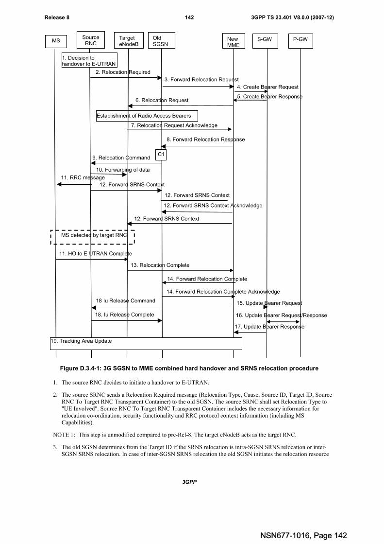
3GPP
3GPP TS 23.401 V8.0.0 (2007-12)142Release 8
TargeteNodeB
SourceRNC
OldSGSN
NewMME
S-GW
3. Forward Relocation Request
6. Relocation Request
2. Relocation Required
9. Relocation Command
8. Forward Relocation Response
7. Relocation Request Acknowledge
MS
12. Forward SRNS Context
12. Forward SRNS Context
12. Forward SRNS Context
11. RRC message
11. HO to E-UTRAN Complete
MS detected by target RNC
Establishment of Radio Access Bearers
C1
10. Forwarding of data
12. Forward SRNS Context Acknowledge
13. Relocation Complete
14. Forward Relocation Complete
19. Tracking Area Update
15. Update Bearer Request18 Iu Release Command
18. Iu Release Complete
17. Update Bearer Response
14. Forward Relocation Complete Acknowledge
16. Update Bearer Request/Response
P-GW
4. Create Bearer Request
5. Create Bearer Response
1. Decision tohandover to E-UTRAN
Figure D.3.4-1: 3G SGSN to MME combined hard handover and SRNS relocation procedure
1. The source RNC decides to initiate a handover to E-UTRAN.
2. The source SRNC sends a Relocation Required message (Relocation Type, Cause, Source ID, Target ID, SourceRNC To Target RNC Transparent Container) to the old SGSN. The source SRNC shall set Relocation Type to"UE Involved". Source RNC To Target RNC Transparent Container includes the necessary information forrelocation co-ordination, security functionality and RRC protocol context information (including MSCapabilities).
NOTE 1: This step is unmodified compared to pre-Rel-8. The target eNodeB acts as the target RNC.
3. The old SGSN determines from the Target ID if the SRNS relocation is intra-SGSN SRNS relocation or inter-SGSN SRNS relocation. In case of inter-SGSN SRNS relocation the old SGSN initiates the relocation resource
NSN677-1016, Page 142
3GPP
3GPP TS 23.401 V8.0.0 (2007-12)143Release 8
allocation procedure by sending a Forward Relocation Request message (IMSI, Tunnel Endpoint IdentifierSignalling, MM Context, PDP Context, Target Identification, RAN Transparent Container, RANAP Cause,GCSI) to the new SGSN. For relocation to an area where Intra Domain Connection of RAN Nodes to MultipleCN Nodes is used, the old SGSN may – if it provides Intra Domain Connection of RAN Nodes to Multiple CNNodes -have multiple target SGSNs for each relocation target in a pool area, in which case the old SGSN willselect one of them to become the new SGSN, as specified in TS 23.236 [30]. PDP context contains GGSNAddress for User Plane and Uplink TEID for Data (to this GGSN Address and Uplink TEID for Data, the oldSGSN and the new SGSN send uplink packets). At the same time a timer is started on the MM and PDP contextsin the old SGSN (see Routeing Area Update procedure in subclause "Location Management Procedures (Iumode)"). The Forward Relocation Request message is applicable only in case of inter-SGSN SRNS relocation.The old SGSN 'sets' the GCSI flag if the MM context contains GPRS CAMEL Subscription Information.
NOTE 2: This step is unmodified compared to pre-Rel-8. The new MME acts the new SGSN, and the PGW as theGGSN. The GGSN user plane address and uplink TEID are the PGW user plane address and TEID. TheMME maps the PDP context parameters to EPS bearers.
4. The MME selects a Serving GW and sends a Create Bearer Request (bearer context(s) with PDN GW addressesand TEIDs for uplink traffic) message to the target Serving GW.
5. The Serving GW allocates the S-GW addresses and TEIDs for the uplink traffic on S1_U reference point (oneTEID per bearer). The target Serving GW sends a Create Bearer Response (Serving GW addresses and uplinkTEID(s) for user plane) message back to the target MME.
6. The target MME requests the target eNodeB to establish the bearer(s) by sending the message RelocationRequest (UE Identifier, Cause, CN Domain Indicator, K_eNB, Integrity protection information (i.e. selectedIntegrity Protection algorithm(s)), Encryption information (i.e. selected Ciphering algorithm(s)), EPS Bearers tobe setup list, Source to Target Transparent Container, Serving GW Address(es) and TEID(s) for User TrafficData, KSI, key derivation parameter).
If the MME has a security association with the UE, the earlier selected NAS and AS security algorithms andrelated keys will be utilized on handover to E-UTRAN. If the MME does not have a security association with theUE, then an operator configured default security algorithm is applied for NAS and AS (UP and RRC) security.KSI and key derivation parameters are targeted for UE. The KSI parameter informs the UE whether a securityassociation exists with the MME and is used or whether it does not exist and UTRAN CK and IK based keys areused in target eNB and in the target MME.
NOTE 3: This step is unmodified compared to TS 23.401. The MME derives the security parameters from thesecurity parameters received from the SGSN.
7. The target eNodeB allocates the requested resources and returns the applicable parameters to the target MME inthe message Relocation Request Acknowledge (Target to Source Transparent Container, EPS Bearers setup list,EPS Bearers failed to setup list).
In addition to the information provided by the MME (KSI, key derivation parameter), the target eNodeB insertseNB C-RNTI that is used to derive target eNB KeNB as well as the RRC and UP keys into the UTRAN RRCmessage, which is contained in the Target to Source Transparent Container.
NOTE 4: This step is unmodified compared to TS 23.401.
8. When resources for the transmission of user data between target RNC and new SGSN have been allocated andthe new SGSN is ready for relocation of SRNS, the Forward Relocation Response (Cause, RAN TransparentContainer, RANAP Cause, Target-RNC Information) message is sent from the new SGSN to the old SGSN. Thismessage indicates that the target RNC is ready to receive from source SRNC the forwarded downlink PDUs, i.e.,the relocation resource allocation procedure is terminated successfully. RAN transparent container and RANAPCause are information from the target RNC to be forwarded to the source SRNC. The Target RNC Information,one information element for each RAB to be set up, contains the RNC Tunnel Endpoint Identifier and RNC IPaddress for data forwarding from the source SRNC to the target RNC. The Forward Relocation Responsemessage is applicable only in case of inter-SGSN SRNS relocation.
NOTE 5: This step is unmodified compared to pre-Rel-8. The new MME acts as the new SGSN, and the targeteNodeB as the target SRNC.
9. The old SGSN continues the relocation of SRNS by sending a Relocation Command message (Target RNC ToSource RNC Transparent Container, RABs To Be Released, RABs Subject To Data Forwarding) to the source
NSN677-1016, Page 143
3GPP
3GPP TS 23.401 V8.0.0 (2007-12)144Release 8
SRNC. The old SGSN decides the RABs to be subject for data forwarding based on QoS, and those RABs shallbe contained in RABs subject to data forwarding. For each RAB subject to data forwarding, the informationelement shall contain RAB ID, Transport Layer Address, and Iu Transport Association. These are the sameTransport Layer Address and Iu Transport Association that the target RNC had sent to new SGSN in RelocationRequest Acknowledge message, and these are used for forwarding of downlink N-PDU from the source SRNCto the target RNC. The source SRNC is now ready to forward downlink user data directly to the target RNC overthe Iu interface. This forwarding is performed for downlink user data only.
NOTE 6: This step is unmodified compared to pre-Rel-8. The target eNodeB acts as the target RNC, and the newMME acts as the new SGSN. Note: The details of the data forwarding between eNodeB and sourceSRNC are FFS.
10. The source SRNC may, according to the QoS profile, begins the forwarding of data for the RABs to be subjectfor data forwarding.
NOTE 7: The order of steps, starting from step 7 onwards, does not necessarily reflect the order of events. Forinstance, source RNC may start data forwarding (step 7), send the RRC message to MS (step 8) andforward SRNS Context message to the old SGSN (step 9) almost simultaneously.
The data forwarding at SRNS relocation shall be carried out through the Iu interface, meaning that the GTP-PDUs exchanged between the source SRNC and the target RNC are duplicated in the source SRNC and routed atthe IP layer towards the target RNC. For each radio bearer which uses lossless PDCP the GTP-PDUs related totransmitted but not yet acknowledged PDCP-PDUs are duplicated and routed at IP layer towards the target RNCtogether with their related downlink PDCP sequence numbers. The source RNC continues transmittingduplicates of downlink data and receiving uplink data.
Before the serving RNC role is not yet taken over by target RNC and when downlink user plane data starts toarrive to target RNC, the target RNC may buffer or discard arriving downlink GTP-PDUs according to therelated QoS profile.
NOTE 8: This step is unmodified compared to pre-Rel-8. The new MME acts as the new SGSN, and the targeteNodeB as the target SRNC. The data forwarding may go directly to target eNodeB or alternatively govia the Serving GW if so decided by new MME and or/ old SGSN in the preparation phase. The details ofthe data forwarding between eNodeB and source SRNC are FFS.
11. Before sending the RRC message the uplink and downlink data transfer shall be suspended in the source SRNCfor RABs, which require delivery order. The RRC message is for example Physical Channel Reconfiguration forRNS to RNS relocation, or Intersystem to UTRAN Handover for BSS to RNS relocation, or Handover fromUTRAN Command for BSS relocation, or Handover Command for BSS to BSS relocation. When the sourceSRNC is ready, the source RNC shall trigger the execution of relocation of SRNS by sending to the MS the RRCmessage provided in the Target RNC to source RNC transparent container, e.g., a Physical ChannelReconfiguration (UE Information Elements, CN Information Elements) message. UE Information Elementsinclude among others new SRNC identity and S-RNTI. CN Information Elements contain among othersLocation Area Identification and Routeing Area Identification.
When the MS has reconfigured itself, it sends an RRC message e.g., a Physical Channel ReconfigurationComplete message to the target SRNC. If the Forward SRNS Context message with the sequence numbers isreceived, the exchange of packets with the MS may start. If this message is not yet received, the target RNC maystart the packet transfer for all RABs, which do not require maintaining the delivery order.
NOTE 9: This step is unmodified compared to pre-Rel-8. This text is valid for the RRC message sent from sourceRNC to the UE. When the UE has got access to target eNodeB it sends the HO to E-UTRAN Completemessage. This RRC message received as part of Target to Source Transparent Container, includesinformation about the selected security algorithms and related key information. Based on this information,the UE selects the same algorithms for the NAS in case the KSI value indicates that the MME has nosecurity association with the UE. In case the KSI value indicates that the MME has a security associationwith the UE, but the UE has lost the security context of the E-UTRAN side (error case), the UE will startAttach procedure on the E-UTRAN side
12. The source SRNC continues the execution of relocation of SRNS by sending a Forward SRNS Context (RABContexts) message to the target RNC via the old and the new SGSN. The Forward SRNS Context message isacknowledged by a Forward SRNS Context Acknowledge message, from new to old SGSN. The purpose of thisprocedure is to transfer SRNS contexts from the source RNC to the target RNC, and to move the SRNS rolefrom the source RNC to the target RNC. SRNS contexts are sent for each concerned RAB and contain the
NSN677-1016, Page 144
3GPP
3GPP TS 23.401 V8.0.0 (2007-12)145Release 8
sequence numbers of the GTP PDUs next to be transmitted in the uplink and downlink directions and the nextPDCP sequence numbers that would have been used to send and receive data from the MS. PDCP sequencenumbers are only sent by the source RNC for the radio bearers which used lossless PDCP [57]. The use oflossless PDCP is selected by the RNC when the radio bearer is set up or reconfigured. For PDP context(s) usingdelivery order not required (QoS profile), the sequence numbers of the GTP-PDUs next to be transmitted are notused by the target RNC.
If delivery order is required (QoS profile), consecutive GTP-PDU sequence numbering shall be maintainedthroughout the lifetime of the PDP context(s). Therefore, during the entire SRNS relocation procedure for thePDP context(s) using delivery order required (QoS profile), the responsible GTP-U entities (RNCs and GGSN)shall assign consecutive GTP-PDU sequence numbers to user packets belonging to the same PDP context uplinkand downlink, respectively.
The target RNC establishes and/or restarts the RLC and exchanges the PDCP sequence numbers (PDCP-SNU,PDCP-SND) between the target RNC and the MS. PDCP-SND is the PDCP sequence number for the nextexpected in-sequence downlink packet to be received by the MS per radio bearer, which used lossless PDCP inthe source RNC. PDCP-SND confirms all mobile terminated packets successfully transferred before the SRNCrelocation. If PDCP-SND confirms reception of packets that were forwarded from the source SRNC, then thetarget SRNC shall discard these packets. PDCP-SNU is the PDCP sequence number for the next expected in-sequence uplink packet to be received in the RNC per radio bearer, which used lossless PDCP in the sourceRNC. PDCP-SNU confirms all mobile originated packets successfully transferred before the SRNC relocation. IfPDCP-SNU confirms reception of packets that were received in the source SRNC, the MS shall discard thesepackets.
NOTE 10:This step is unmodified compared to pre-Rel-8. The new MME acts as the new SGSN, and the targeteNodeB as the target SRNC. The forward SRNS Context message from new MME to the target eNodeBis defined in TS 23.401. The whole SRNS context handling including PDCP sequence number handlingand GTP numbering is FFS.
13. When the UE has successfully accessed the target eNodeB, the target eNodeB informs the target MME bysending the message Relocation Complete.
NOTE 11:This step is unmodified compared to TS 23.401.
14. Upon receipt of Relocation Complete message, if the SRNS Relocation is an inter SGSN SRNS relocation, thenew SGSN signals to the old SGSN the completion of the SRNS relocation procedure by sending a ForwardRelocation Complete message.
NOTE 12:This step is unmodified compared to pre-Rel-8. The new MME acts as the new SGSN.
15. The target MME will now complete the PS Handover procedure by informing the Serving GW that the targetMME is now responsible for all the bearers the UE have established. This is performed in the message UpdateBearer Request (Cause, Tunnel Endpoint Identifier Control Plane, NSAPI, MME Address for Control Plane,eNodeB Address(es) and TEID(s) for User Traffic, and RAT type).
NOTE 13:This step is unmodified compared to TS 23.401.
16. The Serving GW may inform the PDN GW the change of for example the RAT type that e.g. can be used forcharging, by sending the message Update Bearer Request. The PDN GW must acknowledge the request with themessage Update Bearer Response. This is FFS.
NOTE 14:This step is unmodified compared to TS 23.401.
17. The Serving GW acknowledges the user plane switch to the target MME via the message Update BearerResponse (Cause, Tunnel Endpoint Identifier Control Plane, and Serving GW Address for Control Plane). At thisstage the user plane path is established for all bearers between the UE, target eNodeB, Serving GW and PDNGW.
NOTE 15:This step is unmodified compared to TS 23.401.
18. Upon receiving the Relocation Complete message or, if it is an inter-SGSN SRNS relocation, the ForwardRelocation Complete message, the old SGSN sends an Iu Release Command message to the source RNC. Whenthe RNC data-forwarding timer has expired, the source RNC responds with an Iu Release Complete message.
NOTE 16:This step is unmodified compared to pre-Rel-8.
NSN677-1016, Page 145
3GPP
3GPP TS 23.401 V8.0.0 (2007-12)146Release 8
19. If the UE is handovered to a TA that it has not registered with the network, the UE initiates the Tracking AreaUpdate procedure.
The CAMEL procedures are FFS.
If the SRNS Relocation is inter-SGSN, then the following CAMEL procedure calls shall be performed (see referencedprocedures in TS 23.078 [29])
C1) CAMEL_GPRS_PDP_Context_Disconnection, CAMEL_GPRS_Detach and CAMEL_PS_Notification.
They are called in the following order:
- The CAMEL_GPRS_PDP_Context_Disconnection procedure is called several times: once per PDP context.The procedure returns as result "Continue".
- Then the CAMEL_GPRS_Detach procedure is called once. The procedure returns as result "Continue".
- Then the CAMEL_PS_Notification procedure is called once. The procedure returns as result "Continue".
The new SGSN shall determine the Maximum APN restriction based on the received APN Restriction of each PDPcontext from the GGSN and then store the new Maximum APN restriction value.
If the SRNS Relocation is intra-SGSN, then the above mentioned CAMEL procedures calls shall not be performed.
If Routeing Area Update occurs, the SGSN shall determine whether Direct Tunnel can be used based on the receivedGPRS CAMEL Subscription Information. If Direct Tunnel can not be maintained the SGSN shall re-establish RABsand initiate the Update PDP Context procedure to update the IP Address and TEID for Uplink and Downlink data.
If Routeing Area Update occurs, then the following CAMEL procedure calls shall be performed (see referencedprocedures in TS 23.078 [29]):
C2) CAMEL_GPRS_Routeing_Area_Update_Session and CAMEL_PS_Notification.
They are called in the following order:
- The CAMEL_GPRS_Routeing_Area_Update_Session procedure is called. In Figure 42, the procedurereturns as result "Continue".
- Then the CAMEL_PS_Notification procedure is called. The procedure returns as result "Continue".
C3) CAMEL_GPRS_Routeing_Area_Update_Context.
This procedure is called several times: once per PDP context. It returns as result "Continue".
For C2 and C3: refer to Routing Area Update procedure description for detailed message flow.
D.3.5 MME to 2G SGSN Routeing Area Update
The MME to 2G SGSN Routeing Area Update procedure is illustrated in Figure D.3.5-1.
Any steps descriptions that are from TS 23.060 [7] are shown as blue text and remain unmodified. In that stepdescriptions an MS stands for UE, old SGSN for old MME and GGSN for P-GW.
The same procedure applies for Rel-8 SGSN to pre-Rel-8 SGSN RAU. In this case the old MME is an old Rel-8 SGSN.
NSN677-1016, Page 146
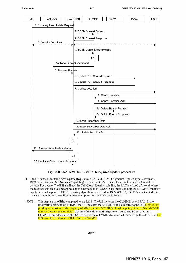
3GPP
3GPP TS 23.401 V8.0.0 (2007-12)147Release 8
MS eNodeB new SGSN HSSS-GWold MME
2. SGSN Context Response
3. Security Functions
1. Routeing Area Update Request
2. SGSN Context Request
6. Update PDP Context Request
6. Update PDP Context Response
7. Update Location
10. Update Location Ack
11. Routeing Area Update Accept
8. Cancel Location
8. Cancel Location Ack
9. Insert Subscriber Data Ack
9. Insert Subscriber Data
5. Forward Packets
4. SGSN Context Acknowledge
C3
C2
C1
P-GW
4a. Data Forward Command
8a. Delete Bearer Request
8a. Delete Bearer Response
12. Routeing Area Update Complete
Figure D.3.5-1: MME to SGSN Routeing Area Update procedure
1. The MS sends a Routeing Area Update Request (old RAI, old P-TMSI Signature, Update Type, Classmark,DRX parameters and MS Network Capability) to the new SGSN. Update Type shall indicate RA update orperiodic RA update. The BSS shall add the Cell Global Identity including the RAC and LAC of the cell wherethe message was received before passing the message to the SGSN. Classmark contains the MS GPRS multislotcapabilities and supported GPRS ciphering algorithms as defined in TS 24.008 [13]. DRX Parameters indicateswhether or not the MS uses discontinuous reception and the DRX cycle length.
NOTE 1: This step is unmodified compared to pre-Rel-8. The UE indicates the GUMMEI as old RAI . In theinformation element old P-TMSI, the UE indicates the M-TMSI that is allocated to the UE. (This is FFSpending conclusion on the mapping of MMEC to the P-TMSI field and mapping of part of the M-TMSIto the P-TMSI signature field). Coding of the old P-TMSI signature is FFS. The SGSN uses theGUMMEI (encoded as the old RAI) to derive the old MME like specified for deriving the old SGSN. It isFFS how the UE derives a TLLI from the S-TMSI.
NSN677-1016, Page 147
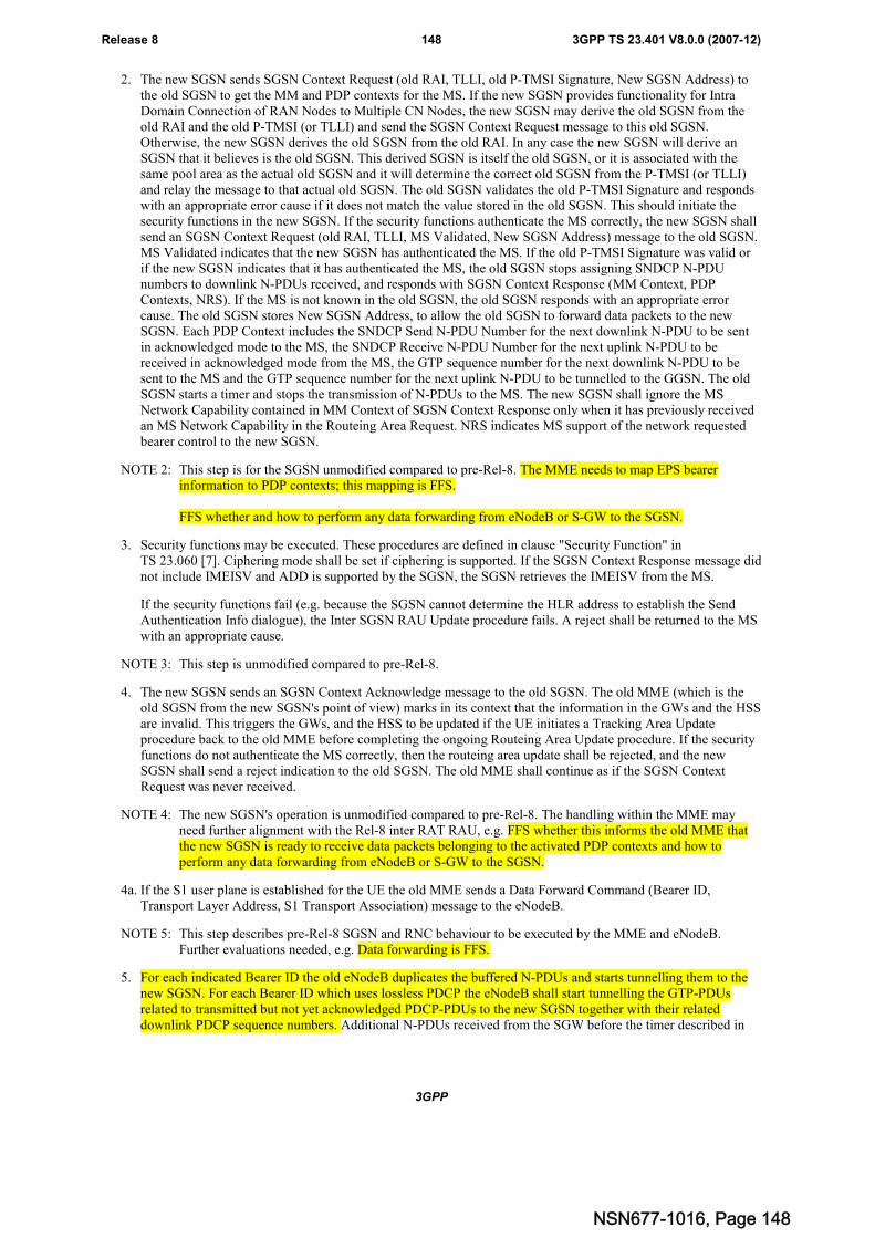
3GPP
3GPP TS 23.401 V8.0.0 (2007-12)148Release 8
2. The new SGSN sends SGSN Context Request (old RAI, TLLI, old P-TMSI Signature, New SGSN Address) tothe old SGSN to get the MM and PDP contexts for the MS. If the new SGSN provides functionality for IntraDomain Connection of RAN Nodes to Multiple CN Nodes, the new SGSN may derive the old SGSN from theold RAI and the old P-TMSI (or TLLI) and send the SGSN Context Request message to this old SGSN.Otherwise, the new SGSN derives the old SGSN from the old RAI. In any case the new SGSN will derive anSGSN that it believes is the old SGSN. This derived SGSN is itself the old SGSN, or it is associated with thesame pool area as the actual old SGSN and it will determine the correct old SGSN from the P-TMSI (or TLLI)and relay the message to that actual old SGSN. The old SGSN validates the old P-TMSI Signature and respondswith an appropriate error cause if it does not match the value stored in the old SGSN. This should initiate thesecurity functions in the new SGSN. If the security functions authenticate the MS correctly, the new SGSN shallsend an SGSN Context Request (old RAI, TLLI, MS Validated, New SGSN Address) message to the old SGSN.MS Validated indicates that the new SGSN has authenticated the MS. If the old P-TMSI Signature was valid orif the new SGSN indicates that it has authenticated the MS, the old SGSN stops assigning SNDCP N-PDUnumbers to downlink N-PDUs received, and responds with SGSN Context Response (MM Context, PDPContexts, NRS). If the MS is not known in the old SGSN, the old SGSN responds with an appropriate errorcause. The old SGSN stores New SGSN Address, to allow the old SGSN to forward data packets to the newSGSN. Each PDP Context includes the SNDCP Send N-PDU Number for the next downlink N-PDU to be sentin acknowledged mode to the MS, the SNDCP Receive N-PDU Number for the next uplink N-PDU to bereceived in acknowledged mode from the MS, the GTP sequence number for the next downlink N-PDU to besent to the MS and the GTP sequence number for the next uplink N-PDU to be tunnelled to the GGSN. The oldSGSN starts a timer and stops the transmission of N-PDUs to the MS. The new SGSN shall ignore the MSNetwork Capability contained in MM Context of SGSN Context Response only when it has previously receivedan MS Network Capability in the Routeing Area Request. NRS indicates MS support of the network requestedbearer control to the new SGSN.
NOTE 2: This step is for the SGSN unmodified compared to pre-Rel-8. The MME needs to map EPS bearerinformation to PDP contexts; this mapping is FFS.
FFS whether and how to perform any data forwarding from eNodeB or S-GW to the SGSN.
3. Security functions may be executed. These procedures are defined in clause "Security Function" inTS 23.060 [7]. Ciphering mode shall be set if ciphering is supported. If the SGSN Context Response message didnot include IMEISV and ADD is supported by the SGSN, the SGSN retrieves the IMEISV from the MS.
If the security functions fail (e.g. because the SGSN cannot determine the HLR address to establish the SendAuthentication Info dialogue), the Inter SGSN RAU Update procedure fails. A reject shall be returned to the MSwith an appropriate cause.
NOTE 3: This step is unmodified compared to pre-Rel-8.
4. The new SGSN sends an SGSN Context Acknowledge message to the old SGSN. The old MME (which is theold SGSN from the new SGSN's point of view) marks in its context that the information in the GWs and the HSSare invalid. This triggers the GWs, and the HSS to be updated if the UE initiates a Tracking Area Updateprocedure back to the old MME before completing the ongoing Routeing Area Update procedure. If the securityfunctions do not authenticate the MS correctly, then the routeing area update shall be rejected, and the newSGSN shall send a reject indication to the old SGSN. The old MME shall continue as if the SGSN ContextRequest was never received.
NOTE 4: The new SGSN's operation is unmodified compared to pre-Rel-8. The handling within the MME mayneed further alignment with the Rel-8 inter RAT RAU, e.g. FFS whether this informs the old MME thatthe new SGSN is ready to receive data packets belonging to the activated PDP contexts and how toperform any data forwarding from eNodeB or S-GW to the SGSN.
4a. If the S1 user plane is established for the UE the old MME sends a Data Forward Command (Bearer ID,Transport Layer Address, S1 Transport Association) message to the eNodeB.
NOTE 5: This step describes pre-Rel-8 SGSN and RNC behaviour to be executed by the MME and eNodeB.Further evaluations needed, e.g. Data forwarding is FFS.
5. For each indicated Bearer ID the old eNodeB duplicates the buffered N-PDUs and starts tunnelling them to thenew SGSN. For each Bearer ID which uses lossless PDCP the eNodeB shall start tunnelling the GTP-PDUsrelated to transmitted but not yet acknowledged PDCP-PDUs to the new SGSN together with their relateddownlink PDCP sequence numbers. Additional N-PDUs received from the SGW before the timer described in
NSN677-1016, Page 148
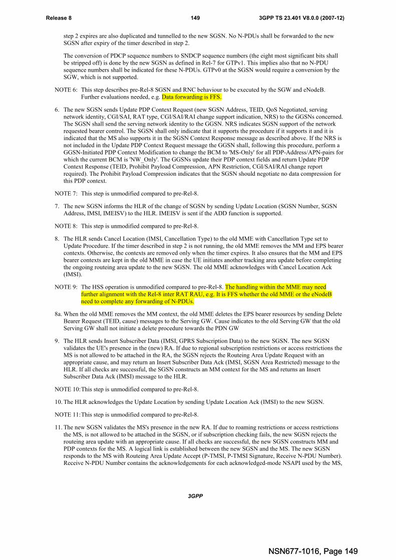
3GPP
3GPP TS 23.401 V8.0.0 (2007-12)149Release 8
step 2 expires are also duplicated and tunnelled to the new SGSN. No N-PDUs shall be forwarded to the newSGSN after expiry of the timer described in step 2.
The conversion of PDCP sequence numbers to SNDCP sequence numbers (the eight most significant bits shallbe stripped off) is done by the new SGSN as defined in Rel-7 for GTPv1. This implies also that no N-PDUsequence numbers shall be indicated for these N-PDUs. GTPv0 at the SGSN would require a conversion by theSGW, which is not supported.
NOTE 6: This step describes pre-Rel-8 SGSN and RNC behaviour to be executed by the SGW and eNodeB.Further evaluations needed, e.g. Data forwarding is FFS.
6. The new SGSN sends Update PDP Context Request (new SGSN Address, TEID, QoS Negotiated, servingnetwork identity, CGI/SAI, RAT type, CGI/SAI/RAI change support indication, NRS) to the GGSNs concerned.The SGSN shall send the serving network identity to the GGSN. NRS indicates SGSN support of the networkrequested bearer control. The SGSN shall only indicate that it supports the procedure if it supports it and it isindicated that the MS also supports it in the SGSN Context Response message as described above. If the NRS isnot included in the Update PDP Context Request message the GGSN shall, following this procedure, perform aGGSN-Initiated PDP Context Modification to change the BCM to 'MS-Only' for all PDP-Address/APN-pairs forwhich the current BCM is 'NW_Only'. The GGSNs update their PDP context fields and return Update PDPContext Response (TEID, Prohibit Payload Compression, APN Restriction, CGI/SAI/RAI change reportrequired). The Prohibit Payload Compression indicates that the SGSN should negotiate no data compression forthis PDP context.
NOTE 7: This step is unmodified compared to pre-Rel-8.
7. The new SGSN informs the HLR of the change of SGSN by sending Update Location (SGSN Number, SGSNAddress, IMSI, IMEISV) to the HLR. IMEISV is sent if the ADD function is supported.
NOTE 8: This step is unmodified compared to pre-Rel-8.
8. The HLR sends Cancel Location (IMSI, Cancellation Type) to the old MME with Cancellation Type set toUpdate Procedure. If the timer described in step 2 is not running, the old MME removes the MM and EPS bearercontexts. Otherwise, the contexts are removed only when the timer expires. It also ensures that the MM and EPSbearer contexts are kept in the old MME in case the UE initiates another tracking area update before completingthe ongoing routeing area update to the new SGSN. The old MME acknowledges with Cancel Location Ack(IMSI).
NOTE 9: The HSS operation is unmodified compared to pre-Rel-8. The handling within the MME may needfurther alignment with the Rel-8 inter RAT RAU, e.g. It is FFS whether the old MME or the eNodeBneed to complete any forwarding of N-PDUs.
8a. When the old MME removes the MM context, the old MME deletes the EPS bearer resources by sending DeleteBearer Request (TEID, cause) messages to the Serving GW. Cause indicates to the old Serving GW that the oldServing GW shall not initiate a delete procedure towards the PDN GW
9. The HLR sends Insert Subscriber Data (IMSI, GPRS Subscription Data) to the new SGSN. The new SGSNvalidates the UE's presence in the (new) RA. If due to regional subscription restrictions or access restrictions theMS is not allowed to be attached in the RA, the SGSN rejects the Routeing Area Update Request with anappropriate cause, and may return an Insert Subscriber Data Ack (IMSI, SGSN Area Restricted) message to theHLR. If all checks are successful, the SGSN constructs an MM context for the MS and returns an InsertSubscriber Data Ack (IMSI) message to the HLR.
NOTE 10:This step is unmodified compared to pre-Rel-8.
10. The HLR acknowledges the Update Location by sending Update Location Ack (IMSI) to the new SGSN.
NOTE 11:This step is unmodified compared to pre-Rel-8.
11. The new SGSN validates the MS's presence in the new RA. If due to roaming restrictions or access restrictionsthe MS, is not allowed to be attached in the SGSN, or if subscription checking fails, the new SGSN rejects therouteing area update with an appropriate cause. If all checks are successful, the new SGSN constructs MM andPDP contexts for the MS. A logical link is established between the new SGSN and the MS. The new SGSNresponds to the MS with Routeing Area Update Accept (P-TMSI, P-TMSI Signature, Receive N-PDU Number).Receive N-PDU Number contains the acknowledgements for each acknowledged-mode NSAPI used by the MS,
NSN677-1016, Page 149
3GPP
3GPP TS 23.401 V8.0.0 (2007-12)150Release 8
thereby confirming all mobile-originated N-PDUs successfully transferred before the start of the updateprocedure.
NOTE 12:This step is unmodified compared to pre-Rel-8. It is FFS whether and how N-PDU numbers are used, e.g.the MME may set the numbers to 0 when creating a context for transferring to the SGSN.
12. The MS acknowledges the new P-TMSI by returning a Routeing Area Update Complete (Receive N-PDUNumber) message to the SGSN. Receive N-PDU Number contains the acknowledgements for eachacknowledged-mode NSAPI used by the MS, thereby confirming all mobile-terminated N-PDUs successfullytransferred before the start of the update procedure. If Receive N-PDU Number confirms reception of N-PDUsthat were forwarded from the old SGSN, these N-PDUs shall be discarded by the new SGSN. LLC and SNDCPin the MS are reset.
NOTE 13:This step is unmodified compared to pre-Rel-8. It is FFS whether and how N-PDU numbers are used, e.g.the UE might ignore any received N-PDU numbers.
13. When the timer started in step 2) expires the old MME releases any eNodeB and Serving GW resources (notshown in the flow).
In the case of a rejected routeing area update operation, due to regional subscription, roaming restrictions, accessrestrictions (see TS 23.221 [27] and TS 23.008 [28]) or because the SGSN cannot determine the HLR address toestablish the locating updating dialogue, the new SGSN shall not construct an MM context. A reject shall be returned tothe MS with an appropriate cause. The MS does not re-attempt a routeing area update to that RA. The RAI value shallbe deleted when the MS is powered-up.
If the new SGSN is unable to update the PDP context in one or more GGSNs, the new SGSN shall deactivate thecorresponding PDP contexts as described in clause "SGSN-initiated PDP Context Deactivation Procedure". This shallnot cause the SGSN to reject the routeing area update.
The PDP Contexts shall be sent from old to new SGSN in a prioritized order, i.e. the most important PDP Context firstin the SGSN Context Response message. (The prioritization method is implementation dependent, but should be basedon the current activity).
The new SGSN shall determine the Maximum APN restriction based on the received APN Restriction of each PDPcontext from the GGSN and then store the new Maximum APN restriction value.
If the new SGSN is unable to support the same number of active PDP contexts as received from old SGSN, the newSGSN should use the prioritisation sent by old SGSN as input when deciding which PDP contexts to maintain activeand which ones to delete. In any case, the new SGSN shall first update all contexts in one or more GGSNs and thendeactivate the context(s) that it cannot maintain as described in subclause "SGSN-initiated PDP Context DeactivationProcedure". This shall not cause the SGSN to reject the routeing area update.
If the timer described in step 2 expires and no Cancel Location (IMSI) was received from the HLR, the old SGSN stopsforwarding N-PDUs to the new SGSN.
If the routeing area update procedure fails a maximum allowable number of times, or if the SGSN returns a RouteingArea Update Reject (Cause) message, the MS shall enter IDLE state.
The CAMEL procedures are FFS.
The CAMEL procedure calls shall be performed, see referenced procedures in TS 23.078 [29]:
C1) CAMEL_GPRS_PDP_Context_Disconnection, CAMEL_GPRS_Detach and CAMEL_PS_Notification.
They are called in the following order:
- The CAMEL_GPRS_PDP_Context_Disconnection procedure is called several times: once per PDP context.The procedure returns as result "Continue".
- Then the CAMEL_GPRS_Detach procedure is called once. The procedure returns as result "Continue".
- Then the CAMEL_PS_Notification procedure is called once. The procedure return as result "Continue".
C2) CAMEL_GPRS_Routeing_Area_Update_Session and CAMEL_PS_Notification.
They are called in the following order:
NSN677-1016, Page 150
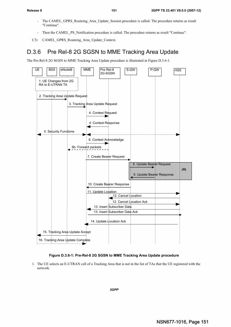
3GPP
3GPP TS 23.401 V8.0.0 (2007-12)151Release 8
- The CAMEL_GPRS_Routeing_Area_Update_Session procedure is called. The procedure returns as result"Continue".
- Then the CAMEL_PS_Notification procedure is called. The procedure returns as result "Continue".
C3) CAMEL_GPRS_Routeing_Area_Update_Context.
D.3.6 Pre Rel-8 2G SGSN to MME Tracking Area Update
The Pre-Rel-8 2G SGSN to MME Tracking Area Update procedure is illustrated in Figure D.3.6-1.
2. Tracking Area Update Request
11. Update Location
14. Update Location Ack
4. Context Response
5. Security Functions
15. Tracking Area Update Accept
12. Cancel Location
12. Cancel Location Ack
6. Context Acknowledge
4. Context Request
16. Tracking Area Update Complete
BSS eNodeB Pre Rel-82G-SGSN
MME S-GW P-GW HSS
1. UE Changes from 2GRA to E-UTRAN TA
3. Tracking Area Update Request
7. Create Bearer Request
10. Create Bearer Response
8. Update Bearer Request
9. Update Bearer Response
6b. Forward packets
(A)
13. Insert Subscriber Data
13. Insert Subscriber Data Ack
UE
Figure D.3.6-1: Pre-Rel-8 2G SGSN to MME Tracking Area Update procedure
1. The UE selects an E-UTRAN cell of a Tracking Area that is not in the list of TAs that the UE registered with thenetwork.
NSN677-1016, Page 151
3GPP
3GPP TS 23.401 V8.0.0 (2007-12)152Release 8
2. The UE sends a Tracking Area Update Request (old P-TMSI, old RAI, old S-TMSI Signature, old GUTI (ifavailable), Selected Network, UE Network Capability, active flag) message to the new MME. Active flag is arequest by UE to activate the radio and S1 bearers for all the active EPS Bearers by the TAU procedure. In theinformation element old P-TMSI, the UE indicates the P-TMSI that is allocated to the UE.
Editor's note: FFS whether all or selected bearers shall be established as part of the TAU procedure when 'activeflag' indicates that the UE wants to re-establish bearers.
3. The eNodeB shall add the E-UTRAN Area Identity before forwarding the message to the MME. This E-UTRANArea Identity is a globally unique E-UTRAN ID for the eNodeB the UE is connected to. The eNodeB derives theMME from the old GUMMEI (contained within the old GUTI) and the indicated Selected Network. If thatGUMMEI is not associated with the eNodeB, or the GUMMEI is not available, the eNodeB selects the MME asdescribed in clause 4.3.8.3 on "MME Selection Function". The eNodeB forwards the TAU Request messagetogether with an indication of the Cell Global Identity of the cell from where it received the message and withthe Selected Network to the MME.
Editor's note: It has yet to be determined whether message 1 is only sent in ECM-CONNECTED state (e.g. it ispreceded by a Service Request (type=signalling) procedure), or, whether message 1 can be used toestablish an S1 connection (in which case, the message needs to carry the S-TMSI).
4 The new SGSN sends SGSN Context Request (old RAI, TLLI, old P-TMSI Signature, New SGSN Address) tothe old SGSN to get the MM and PDP contexts for the MS. If the new SGSN provides functionality for IntraDomain Connection of RAN Nodes to Multiple CN Nodes, the new SGSN may derive the old SGSN from theold RAI and the old P-TMSI (or TLLI) and send the SGSN Context Request message to this old SGSN.Otherwise, the new SGSN derives the old SGSN from the old RAI. In any case the new SGSN will derive anSGSN that it believes is the old SGSN. This derived SGSN is itself the old SGSN, or it is associated with thesame pool area as the actual old SGSN and it will determine the correct old SGSN from the P-TMSI (or TLLI)and relay the message to that actual old SGSN. The old 2G-SGSN validates the old P TMSI Signature andresponds with an appropriate error cause if it does not match the value stored in the old 2G SGSN. This shouldinitiate the security functions in the new SGSN. If the security functions authenticate the MS correctly, the newSGSN shall send an SGSN Context Request (old RAI, old PTMSI, MS Validated, New SGSN Address) messageto the old SGSN. MS Validated indicates that the new SGSN has authenticated the MS. If the old P-TMSISignature was valid or if the new SGSN indicates that it has authenticated the MS, the old SGSN stops assigningSNDCP N-PDU numbers to downlink N-PDUs received, and responds with SGSN Context Response (MMContext, PDP Contexts). If the MS is not known in the old SGSN, the old SGSN responds with an appropriateerror cause. The old SGSN stores New SGSN Address, to allow the old SGSN to forward data packets to thenew SGSN. Each PDP Context includes the SNDCP Send N-PDU Number for the next downlink N-PDU to besent in acknowledged mode to the MS, the SNDCP Receive N-PDU Number for the next uplink N-PDU to bereceived in acknowledged mode from the MS, the GTP sequence number for the next downlink N-PDU to besent to the MS and the GTP sequence number for the next uplink N-PDU to be tunnelled to the GGSN. The oldSGSN starts a timer and stops the transmission of N-PDUs to the MS. The new SGSN shall ignore the MSNetwork Capability contained in MM Context of SGSN Context Response only when it has previously receivedan MS Network Capability in the Routeing Area Request.
Editor note: It is FFS whether the NRI is also duplicated by the UE to be put in a separate MME field, it isexpected that the UE will send NRI in the appropriate field depending on current RAT.
In the step 3 above, the new "SGSN" shall be understood to be a new "MME" and the old SGSN stores newSGSN Address, to allow the old SGSN to forward data packets to the new "S-GW or eNodeB".
The new MME always support functionality for Intra Domain Connection of RAN Nodes to Multiple CN Nodes
5. Security functions may be executed. Procedures are defined in the clause "Security Function". If the SGSNContext Response message from the old SGSN did not include IMEISV, the MME shall retrieve the ME Identity(the IMEISV) from the MS.
The MME can check the ME Identity with the EIR. Dependent upon the Result received from the EIR, the MMEdecides whether to continue with this TAU procedure or to reject the UE.
6. The new MME sends an SGSN Context Acknowledge message to the old SGSN. This informs the old SGSNthat the new SGSN is ready to receive data packets belonging to the activated PDP contexts. The old SGSNmarks in its context that the MSC/VLR association and the information in the GGSNs and the HLR are invalid.This triggers the MSC/VLR, the GGSNs, and the HLR to be updated if the MS initiates a routeing area updateprocedure back to the old SGSN before completing the ongoing routeing area update procedure. If the security
NSN677-1016, Page 152
3GPP
3GPP TS 23.401 V8.0.0 (2007-12)153Release 8
functions do not authenticate the MS correctly, then the routeing area update shall be rejected, and the newSGSN shall send a reject indication to the old SGSN. The old SGSN shall continue as if the SGSN ContextRequest was never received.
NOTE 1: in the blue text of step 6, new "SGSN" shall be understood as to be a new "MME" and "routing areaupdate" is a "tracking area update" procedure.The MME needs to map PDP contexts received from pre-Rel-8 SGSN into EPS bearer information; thismapping is FFS.
NOTE 2: The SGSN operation is unmodified compared to pre-Rel-8. The handling within the MME may needfurther alignment with the Rel-8 inter RAT RAU, e.g. FFS whether this informs the old SGSN that thenew MME is ready to receive data packets belonging to the activated PDP contexts and how to performany data forwarding from BSS or SGSN to the eNodeB.
Editor's note: It is FFS when eNodeB resources are allocated and how transfer of data with the eNodeB will takeplace
7. The new MME selects a Serving GW and sends an Create Bearer Request (new MME Address and TEID, QoSNegotiated converted, serving network identity, ME Identity, CGI/SAI, RAT type, CGI/SAI/RAI change supportindication, NRS (received from the SGSN)) message to the Serving GW. The MME shall send the servingnetwork identity to the Serving GW.
Editor's note: It is FFS how to handle the case when the UE has no PDP contexts.
8. The Serving GW creates contexts and informs the PDN GW(s) about the change of the RAT type. The ServingGW sends an Update Bearer Request (Serving GW Address and TEID, RAT type, ME Identity, etc.) message tothe PDN GW(s) concerned.
9. The PDN GW updates its context field and returns an Update Bearer Response (PDN GW address and TEID,etc.) message to the Serving GW.
10. The Serving GW updates its context and returns an Create Bearer Response (Serving GW address and TEID,PDN GW address and TEID, etc.) message.
11. The new MME informs the HSS of the change of serving Core Network node by sending an Update Location(MME Address, IMSI, ME Identity) message to the HSS. The ME Identity is included if, in step 4, the SGSNContext Response did not contain the IMEISV.
12. The HSS sends a Cancel Location (IMSI, Cancellation Type) message to the old 2G SGSN. The old 2G SGSNremoves the contexts.
If the timer started in step 3 is not running, the old 2G-SGSN removes the MM context. Otherwise, the contextsare removed when the timer expires. It also ensures that the MM context is kept in the old 2G-SGSN for the casethe UE initiates another TAU procedure before completing the ongoing TAU procedure to the new MME. Theold 2G SGSN acknowledges with a Cancel Location Ack (IMSI) message.
13. The HSS sends Insert Subscriber Data (IMSI, Subscription Data) to the new MME. The new MME validates theMS's presence in the (new) TA. If due to regional subscription restrictions or access restrictions the MS is notallowed to be attached in the TA, the MME rejects the Tracking Area Update Request with an appropriate cause,and may return an Insert Subscriber Data Ack (IMSI, MME Area Restricted) message to the HSS. If all checksare successful, the MME constructs an MM context for the MS and returns an Insert Subscriber Data Ack (IMSI)message to the HSS.
14. The HLR acknowledges the Update Location by sending Update Location Ack (IMSI) to the new MME.
15. The new MME validate the UE's presence in the new TA, after it has received valid and updated subscriptiondata. If due to roaming restrictions or access restrictions the UE is not allowed to be attached in the TA, or ifsubscription checking fails, the new MME rejects the tracking area update with an appropriate cause sent in theTAU Reject message to the UE.
If all checks are successful, the new MME responds to the UE with a Tracking Area Update Accept (GUTI, TAI-list) message. If the "active flag" is set in the TAU Request message the user plane setup procedure can beactivated in conjunction with the TAU Accept message. The procedure is described in detail in TS 36.300 [5].The messages sequence should be the same as for the UE triggered Service Request procedure specified inclause 5.3.4.1 from the step when MME establishes the bearer(s).
NSN677-1016, Page 153
3GPP
3GPP TS 23.401 V8.0.0 (2007-12)154Release 8
16. If the GUTI was included in the TAU Accept message, the UE acknowledges the message by returning aTracking Area Update Complete message to the MME.
NSN677-1016, Page 154
3GPP
3GPP TS 23.401 V8.0.0 (2007-12)155Release 8
Annex E (normative):Mapping between EPS and pre-Rel-8 QoS parametersThis annex specifies how the QoS parameter values of an EPS bearer (E-UTRAN access to the EPS) should be mappedto/from the pre-Rel-8 QoS parameter values of a PDP context (UTRAN/GERAN access to the EPS) before a procedureis triggered that executes a handover between E-UTRAN and UTRAN/GERAN.
The following mapping rules hold:
- There is a one-to-one mapping between an EPS bearer and a PDP context.
Editor's Note: The handling of this principle in case of "dual stack IPv4/IPv6 bearers" is FSS.
- The EPS bearer parameters ARP is mapped one-to-one to/from the GPRS bearer parameter ARP.
Editor's Note: Note that in GPRS pre-Rel-8 the same UE/PDN connection, the system does not expect to have two ormore PDP contexts with different ARP values. This is different in EPS. It is FFS whether this causesconflict / errors or whether a specific mapping rule for ARP is needed.
- The EPS bearer parameters GBR and MBR of a GBR EPS bearer are mapped one-to-one to/from the GPRSbearer parameters GBR and MBR of a PDP context associated with Traffic class 'conversational' or 'streaming'.
Editor's Note: The details of the mapping of GBR, and MBR between GBR EPS bearers and conversational /streaming PDP contexts should be captured in stage 3 specs. Once done this editor's note will be replacedwith a corresponding reference.
- At handover from E-UTRAN to UTRAN/GERAN the GPRS bearer parameter MBR of PDP contexts associatedwith Traffic Class 'interactive' or 'background' is set based on MME operator policy.
NOTE 1: In order to apply the concept of AMBR in UTRAN/GERAN, one such policy may be to set the sum ofthose MBRs to not exceed the value of the EPS bearer parameter AMBR.
NOTE 2: In order to ensure that the MBR of PDP contexts associated with Traffic Class 'interactive' or'background' are restored to their previous values when handing over again from E-UTRAN toUTRAN/GERAN, one such policy may be to have an MME store at handover from UTRAN/GERAN toE-UTRAN the GPRS bearer parameter MBR of PDP contexts associated with Traffic Class 'interactive'or 'background'.
- At handover from UTRAN/GERAN to E-UTRAN the AMBR from the EPS subscribed QoS profile for thecorresponding APN shall take precedence. That is, the GPRS bearer parameter MBR of interactive / backgroundPDP contexts is ignored in this case.
- A standardized value of the EPS bearer parameter QCI is mapped one-to-one to/from values of the pre-Rel-8parameters Traffic Class, Traffic Handling Priority, Signalling Indication, and Source Statistics Descriptor asshown in Table E-1.
- At handover from E-UTRAN to UTRAN/GERAN the setting of the values of the pre-Rel-8 parameters TransferDelay and SDU Error Ratio should be derived from the corresponding QCI's Packet Delay Budget and PacketLoss Rate, respectively. At handover from UTRAN/GERAN to E-UTRAN the values of the pre-Rel-8parameters Transfer Delay and SDU Error Ratio should be ignored.
- The setting of the values of all other pre-Rel-8 QoS is based on operator policy pre-configured in the MME.
NSN677-1016, Page 155
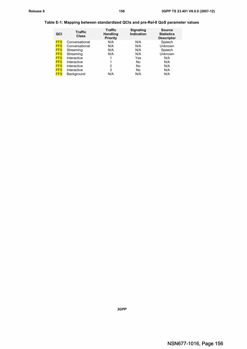
3GPP
3GPP TS 23.401 V8.0.0 (2007-12)156Release 8
Table E-1: Mapping between standardized QCIs and pre-Rel-8 QoS parameter values
QCITrafficClass
TrafficHandlingPriority
SignalingIndication
SourceStatisticsDescriptor
FFS Conversational N/A N/A SpeechFFS Conversational N/A N/A UnknownFFS Streaming N/A N/A SpeechFFS Streaming N/A N/A UnknownFFS Interactive 1 Yes N/AFFS Interactive 1 No N/AFFS Interactive 2 No N/AFFS Interactive 3 No N/AFFS Background N/A N/A N/A
NSN677-1016, Page 156
3GPP
3GPP TS 23.401 V8.0.0 (2007-12)157Release 8
Annex F (normative):Dedicated bearer activation in combination with the AttachprocedureIt shall be possible for the PDN GW to initiate the activation of dedicated bearers (as specified in section 5.4.1) as partof the attach procedure (as specified in section 5.3.2.1) over EUTRAN. However the result of the dedicated beareractivation procedure shall be logically separate from the Attach procedure, meaning that the result of the Attachprocedure is not dependent on whether the Dedicated bearer activation procedure succeeds or not. On the other hand,the dedicated bearer activation may only be regarded as successful if the Attach procedure completes successfully.
The messages of the Dedicated bearer activation can be sent together with the messages of the Attach procedure, asshown in the Figure and explanation below.
Editor's note: It is considered a stage 3 question whether the Create Default Bearer Response message ispiggybacked with the Create Dedicated Bearer Request on S5/S8 and S11, or alternatively other ways areused to tie those messages together such that the MME can recognize that a Create Default BearerResponse message is combined with a Create Dedicated Bearer Request message. However, it isnecessary to ensure that the UE sees that the Dedicated Bearers are established at Attach in order toprevent the UE requesting establishment of the (the same) dedicated resources immediately following theAttach Accept message.
On the S1 and Uu interfaces the messages for the Attach procedure and for the Dedicated Bearer Activation procedureare combined into a single message. If the MME has sent an Attach Accept message towards the eNodeB, and then theMME receives a Create Dedicated Bearer Request before the MME receives the Attach Accept message, the MMEshall wait for the Attach procedure to completes before the MME continues with Dedicated Bearer Activationprocedure.
It shall be possible that multiple dedicated bearers can simultaneously be activated in the signaling flow shown below.
NSN677-1016, Page 157
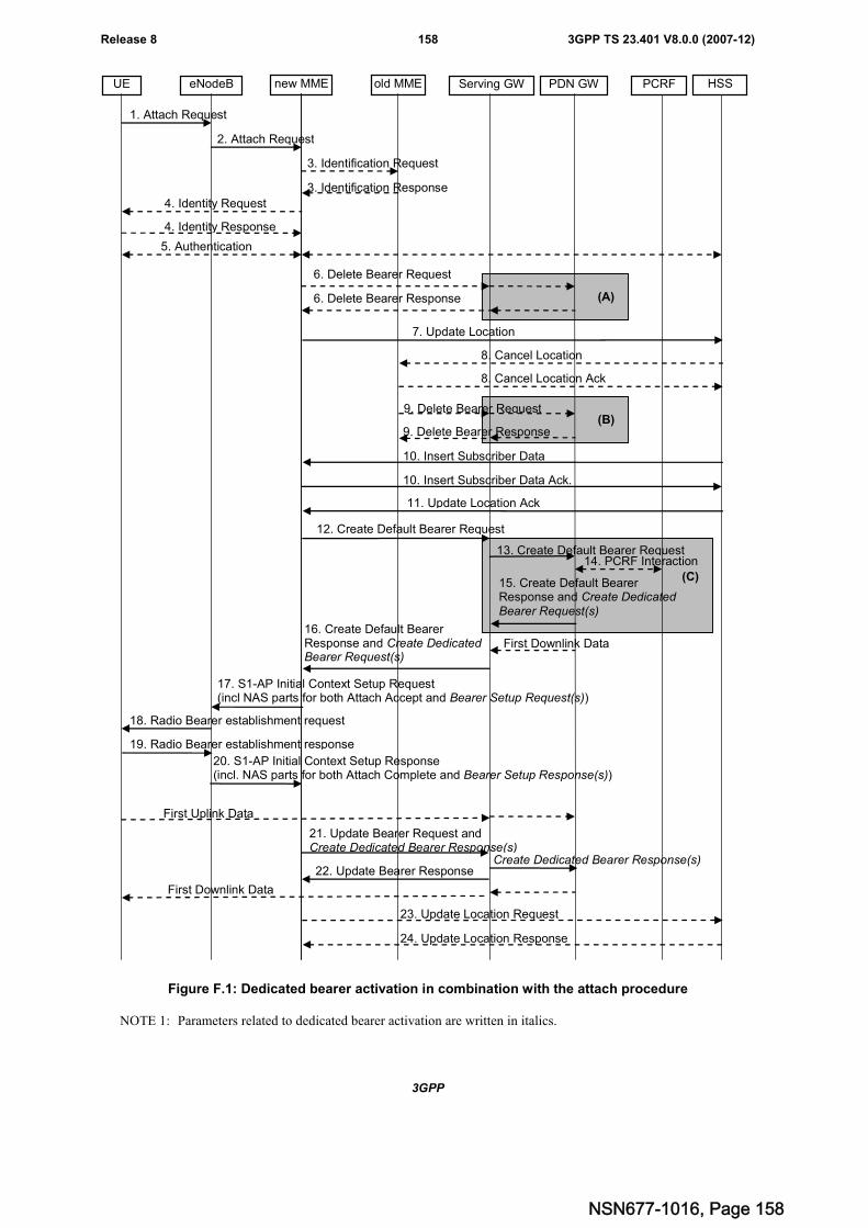
3GPP
3GPP TS 23.401 V8.0.0 (2007-12)158Release 8
(B)
(A)
3. Identification Request
1. Attach Request
new MME old MME Serving GW PCRF HSS
3. Identification Response
PDN GW
2. Attach Request
eNodeBUE
4. Identity Request
4. Identity Response
16. Create Default BearerResponse and Create DedicatedBearer Request(s)
12. Create Default Bearer Request
5. Authentication
7. Update Location
8. Cancel Location
11. Update Location Ack
8. Cancel Location Ack
9. Delete Bearer Request
9. Delete Bearer Response
17. S1-AP Initial Context Setup Request(incl NAS parts for both Attach Accept and Bearer Setup Request(s))
First Uplink Data
13. Create Default Bearer Request
15. Create Default BearerResponse and Create DedicatedBearer Request(s)
6. Delete Bearer Response
6. Delete Bearer Request
10. Insert Subscriber Data
10. Insert Subscriber Data Ack.
14. PCRF Interaction
19. Radio Bearer establishment response
18. Radio Bearer establishment request
20. S1-AP Initial Context Setup Response(incl. NAS parts for both Attach Complete and Bearer Setup Response(s))
22. Update Bearer Response
21. Update Bearer Request andCreate Dedicated Bearer Response(s)
First Downlink Data
First Downlink Data
23. Update Location Request
24. Update Location Response
(C)
Create Dedicated Bearer Response(s)
Figure F.1: Dedicated bearer activation in combination with the attach procedure
NOTE 1: Parameters related to dedicated bearer activation are written in italics.
NSN677-1016, Page 158
3GPP
3GPP TS 23.401 V8.0.0 (2007-12)159Release 8
The following steps below require special attention:
15. (On the P-GW-S-GW interface) Create Default Bearer Response message of the Attach procedure is combinedwith Create Dedicated Bearer Request message of the Dedicated Bearer Activation Procedure
16. (On the S-GW-MME interface) Create Default Bearer Response message of the Attach procedure is combinedwith the Create Dedicated Bearer Request message of the Dedicated Bearer Activation Procedure
17. If the MME receives a Create Default Bearer Response message combined with a Create Dedicated BearerRequest message, the MME shall send the S1-AP Initial Context Setup Request message to the eNodeB,including the NAS parts for both the Attach Accept message of the Attach procedure and the Bearer SetupRequest of the Bearer Activation Procedure.
NOTE 2: The MME shall not send a Bearer Setup Request message of a new Dedicated Bearer Activationprocedure to the eNodeB before sending the Attach Accept message of the Attach procedure to theeNodeB. If the MME has already sent the Attach Accept message of the Attach procedure to the eNodeB,the MME shall wait for the Attach Complete message to arrive before sending a separate Bearer SetupRequest of a Dedicated Bearer Activation procedure.
18-19. The radio bearer establishment of the default and dedicated bearer(s) is performed in the same RRC message.
20. The eNodeB sends the S1-AP Initial Context Setup Response message to the MME, which contains the NASparts for both the Attach Complete message of the Attach procedure and the Bearer Setup Response of theDedicated Bearer Activation Procedure.
21. The Update Bearer Request message of the Attach procedure is combined with the Create Dedicated BearerResponse message of the Dedicated Bearer Activation Procedure. After that, the Serving GW continues withsending a Create Dedicated Bearer Response message to the PDN GW.
NSN677-1016, Page 159
3GPP
3GPP TS 23.401 V8.0.0 (2007-12)160Release 8
Annex G (informative):Differentiation between TS 23.060 and TS 23.401TS 23.060 [7] documents all procedures that are needed for 2G and/or 3G 3GPP access operation.
This specification documents all procedures that are needed for E-UTRAN operation and for interoperation between E-UTRAN and 2G or 3G 3GPP accesses.
Following principles apply for describing procedures in TS 23.060 [7], Rel-8:
- all procedures are shown with S4 and SGW handling when applicable for the procedure;
- it is clarified that SGSN and SGW may be combined, which results in the Rel-7 architecture model and avoidstwo sets of 2G/3G 3GPP Rel-8 procedures;
- GGSN is replaced by PGW and Gn/Gp by S5/S8 in the Rel-8 Architecture figure;
- It is clarified that the PGW contains the Rel-7 GGSN functionality and interfaces, e.g. for interoperation withearlier releases;
- documentation of interoperation procedures between Gn/Gp based SGSN/SGW and pre-Rel-8 GGSNs viaGn/Gp;
- documentation of interoperation procedures between S5/S8 based SGSN/SGW and Gn/Gp based SGSN;
- it is FFS whether the PGW provides GGSN functionality that is not described in TS 23.060 [7] (e.g. MBMS);
- the referencing between TS 23.401 and TS 23.402 for the documentation of the S5/S8 PMIP variant applies alsofor the TS 23.060 [7] procedures;
With that approach Rel-8 TS 23.060 [7] provides all EPC functionality for 2G/3G only procedures and it contains alsothe Rel-7 architecture without a need for a redundant Rel-8 2G/3G 3GPP stage 2 specification.
NSN677-1016, Page 160
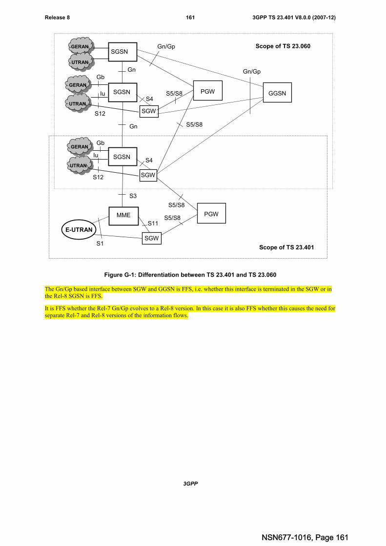
3GPP
3GPP TS 23.401 V8.0.0 (2007-12)161Release 8
Iu
Gn
S1
GERAN
UTRAN
SGSN
E-UTRAN
MME
S11
PGW
UTRAN
SGSN
SGW
S4
Gn/Gp
S5/S8
Gn
UTRAN
SGSN
SGW
S4
Gn/Gp
S5/S8
GGSN
PGW
S5/S8
S5/S8
SGW
S3
Scope of TS 23.060
Scope of TS 23.401
S12
Iu
S12
GERAN
GERAN
Gb
Gb
Figure G-1: Differentiation between TS 23.401 and TS 23.060
The Gn/Gp based interface between SGW and GGSN is FFS, i.e. whether this interface is terminated in the SGW or inthe Rel-8 SGSN is FFS.
It is FFS whether the Rel-7 Gn/Gp evolves to a Rel-8 version. In this case it is also FFS whether this causes the need forseparate Rel-7 and Rel-8 versions of the information flows.
NSN677-1016, Page 161
3GPP
3GPP TS 23.401 V8.0.0 (2007-12)162Release 8
Annex H (informative):Mapping of EPS core network identities to legacy signallingmessagesThis annex provides temporary information on 2 possibilities for the mapping of these identities, e.g. for theconstruction of the Routeing Area Update Request message sent to a pre-Rel-8 SGSN. Other mapping possibilities mayexist.
Clause 5.2 of this specification contains information on the EPS Identities.
In EPS,
<GUTI> = <GUMMEI><M-TMSI>,
where <GUMMEI> = <MCC><MNC><MME Identifier>
and <MME Identifier> = <MME Group ID><MME Code>
It is assumed that MCC and MNC have the same field size as in pre release 8 3GPP systems.
M-TMSI is assumed to have 32 bits.
MME Code is assumed to have 8 bits.
MME Group ID is assumed to have 16 bits (although 1 of these bits might be needed to differentiate the MME GroupID from the LAC in a 2G/3G network.
Possible mapping 1
EPS <MCC> maps to legacy <MCC>
EPS <MNC> maps to legacy <MNC>
EPS <MME Group ID> maps to legacy <LAC>
EPS <MME Code> maps to legacy <RAC>
EPS <M-TMSI> maps to legacy <P-TMSI>
Possible mapping 2
If "abuse" of the legacy P-TMSI signature field is permitted by SA 3, then extra flexibility can be achieved using theabove mapping with the following differences:
- EPS <MME Code> maps to legacy <RAC> AND is also copied into <8 bits of the NRI field within thePTMSI>;
- 24 bits of the EPS <M-TMSI> is mapped into the remaining 24 bits of the legacy <PTMSI>; and
- the remaining 8 bits of the EPS <M-TMSI> are copied into 8 bits of the <P-TMSI signature> field.
NSN677-1016, Page 162
3GPP
3GPP TS 23.401 V8.0.0 (2007-12)163Release 8
Annex I (informative):Guidance for contributors to this specificationThe following guidance is provided for drafting figures for this specification TS 23.401 that contain specific stepswhich are different in TS 23.402 [2] due to the PMIP-based S5/S8 interface:
- Message flows to this specification will contain the complete procedures applicable for GTP-based S5/S8 only.
- In this specification, section(s) of a message flow that is different for PMIP-based S5/S8 interface are shownsurrounded by shaded box indexed by an upper-case letter in ascending order, e.g. "A", "B", "C", etc.
For example, at the bottom of the flow, the following text should be included:
"NOTE: Procedure steps (A) and (B) for an PMIP-based S5/S8 interface are defined in TS 23.402 [2]."
- Further guidance for drafting procedures for TS 23.402 [2] can be found in that specification itself.
NSN677-1016, Page 163
3GPP
3GPP TS 23.401 V8.0.0 (2007-12)164Release 8
Annex J (informative):High Level ISR flowsThe high level ISR flows show only the handling of the TMSIs for simplification. Related RAs/TAs are alwayssignalled with the TMSIs when defined by the detailed procedures. Also other IEs are not shown when not necessaryfor the high level description.
This Annex will be removed once the ISR functionality is captured by the detailed procedures.
ISR follows following principles:
- UE registers to the MME and SGSN separately;
- MME and SGSN register to the HSS and the HSS maintain two PS registrations;
- UE needs to be informed by the CN nodes (SGSN and MME) if the ISR functionality is activated or deactivatedfor that UE;
- There is no "signaling free reselection" of an E-UTRAN cell by a UE in URA_PCH state (e.g. URA_PCH istreated as active mode by the UE/EPC when moving to E-UTRAN);
- When ISR is activated for 2G and/or 3G, Idle Mode UP Termination is in S-GW for that RAT;
- The Serving GW needs to be informed if the ISR functionality is activated or deactivated for a UE;
- Two periodic update timers, running separately in the UE for updating SGSN and MME separately:
- Functionality is needed in SGSN and MME to avoid the deletion of the PDP context/EPS Bearers because ofmissing periodic updates.
NSN677-1016, Page 164
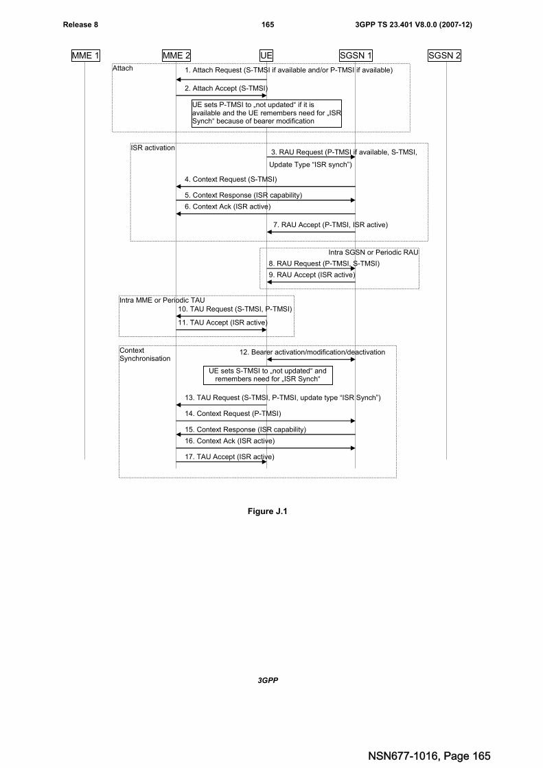
3GPP
3GPP TS 23.401 V8.0.0 (2007-12)165Release 8
Attach
ContextSynchronisation
ISR activation
SGSN 2SGSN 1MME 1 MME 2 UE
1. Attach Request (S-TMSI if available and/or P-TMSI if available)
2. Attach Accept (S-TMSI)
3. RAU Request (P-TMSI if available, S-TMSI,
Update Type “ISR synch”)
4. Context Request (S-TMSI)
5. Context Response (ISR capability)
6. Context Ack (ISR active)
7. RAU Accept (P-TMSI, ISR active)
Intra SGSN or Periodic RAU
8. RAU Request (P-TMSI, S-TMSI)
9. RAU Accept (ISR active)
Intra MME or Periodic TAU10. TAU Request (S-TMSI, P-TMSI)
11. TAU Accept (ISR active)
12. Bearer activation/modification/deactivation
UE sets S-TMSI to „not updated“ andremembers need for „ISR Synch“
13. TAU Request (S-TMSI, P-TMSI, update type “ISR Synch”)
17. TAU Accept (ISR active)
14. Context Request (P-TMSI)
15. Context Response (ISR capability)
16. Context Ack (ISR active)
UE sets P-TMSI to „not updated“ if it isavailable and the UE remembers need for „ISRSynch“ because of bearer modification
Figure J.1
NSN677-1016, Page 165
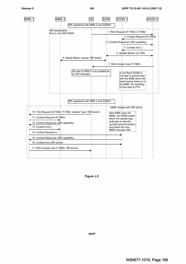
3GPP
3GPP TS 23.401 V8.0.0 (2007-12)166Release 8
MME change with ISR active
ISR deactivationDue to non ISR SGSN
SGSN 2SGSN 1MME 1 MME 2 UE
1. RAU Request (P-TMSI, S-TMSI)
2. Context Request (P-TMSI)
3. Context Response (ISR capability)
4. Context Ack ()
7. RAU Accept (new P-TMSI)
10. TAU Request (S-TMSI, P-TMSI, Update Type: ISR Synch)
11. Context Request (S-TMSI)
12. Context Response (ISR capability)
13. Context Ack ()
ISR registered with MME 2 and SGSN1
UE sets S-TMSI to not updated asno ISR indicated
ISR registered with MME 2 and SGSN1
14. Context Request ()
15. Context Response (ISR capability)
16. Context Ack (ISR active)
17. RAU Accept (new S-TMSI, ISR active)
New MME asks oldMME; old SGSN askedwhen the update typeindicates a need forcontext synchronizationand when the newMME activates ISR
SGW
5. Update Bearer (no ISR)
6. Delete Bearer (cause: ISR deact)
A pre-Rel-8 SGSN isnot able to synchronisewith the MME when thelatest bearer status is inthe MME, the handlingof this case is FFS
Figure J.2
NSN677-1016, Page 166
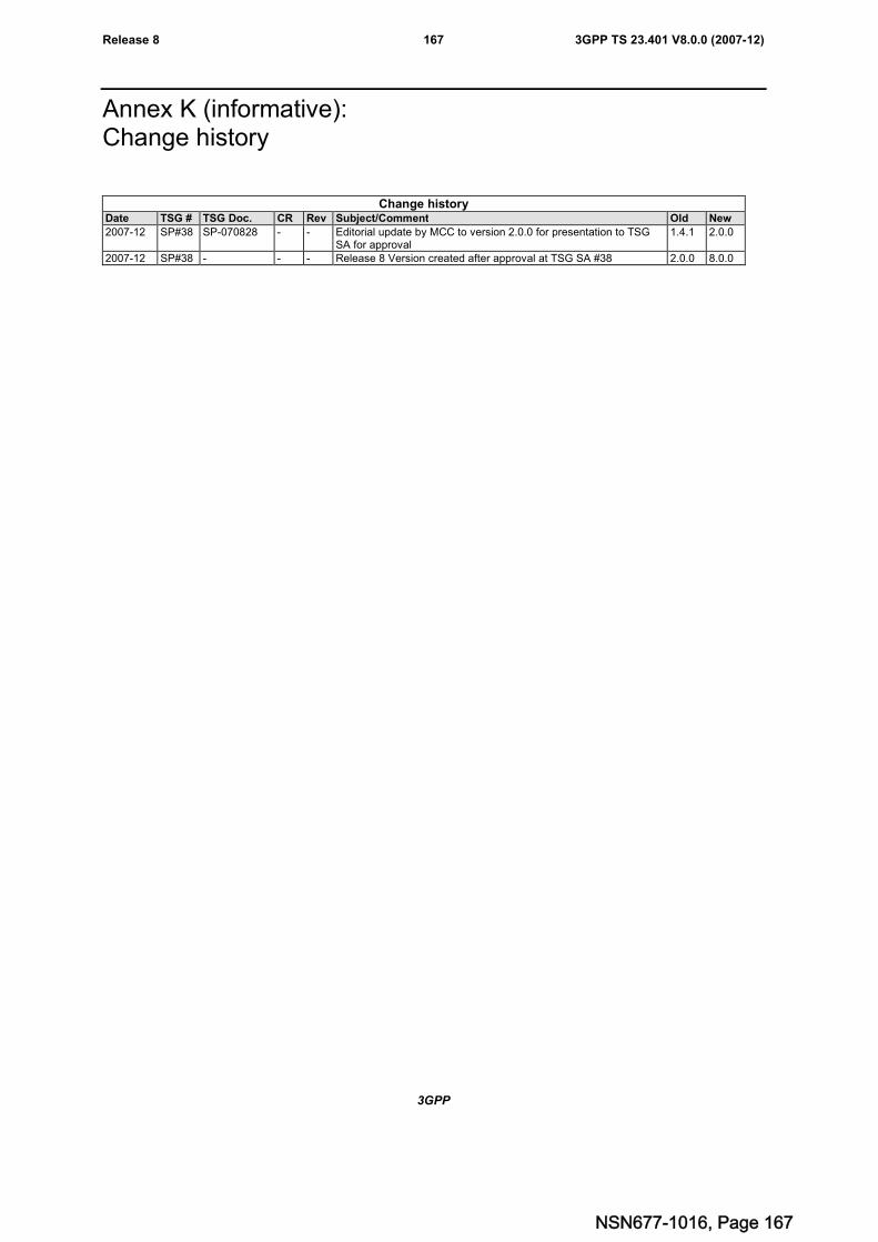
3GPP
3GPP TS 23.401 V8.0.0 (2007-12)167Release 8
Annex K (informative):Change history
Change historyDate TSG # TSG Doc. CR Rev Subject/Comment Old New
2007-12 SP#38 SP-070828 - - Editorial update by MCC to version 2.0.0 for presentation to TSGSA for approval
1.4.1 2.0.0
2007-12 SP#38 - - - Release 8 Version created after approval at TSG SA #38 2.0.0 8.0.0
NSN677-1016, Page 167

![3GPP TS 32.251 V7.3 - Microsoft · 5.2.3 CDR generation ... 3GPP. Release 7 7 3GPP TS 32.251 V7.3.0 ... [11-19] Void. [20] 3GPP TS 32.260: "Telecommunication management;](https://img.pdfslide.us/doc/110x75/5b3ba7e67f8b9a0e628cf248/3gpp-ts-32251-v73-microsoft-523-cdr-generation-3gpp-release-7-7-3gpp.jpg)
![TR 121 905 - V15.0.0 - Digital cellular telecommunications ... · [7] 3GPP TS 23.401: "General Packet Radio Service (GPRS) enhancements for Evolved Universal Terrestrial Radio Access](https://img.pdfslide.us/doc/110x75/5c385dcd09d3f2944f8b77b2/tr-121-905-v1500-digital-cellular-telecommunications-7-3gpp-ts-23401.jpg)


![CBRS Network Service Technical Specifications … · - MulteFire Alliance Technical Specification MFA TS MF.202 [2] and - 3GPP Technical Specification 3GPP TS 23.401 [14]). The modifications](https://img.pdfslide.us/doc/110x75/5b919f1f09d3f274268c0fc1/cbrs-network-service-technical-specifications-multefire-alliance-technical.jpg)