Embed Size (px)
Citation preview

Service Manual
DEALER: KEEP THIS MANUAL. THE PROCEDURESIN THIS MANUAL MUST BE PERFORMED BY ANAUTHORIZED DEALER ONLY
3G Storm Series® Wheelchairs
Arrow® RWDTorque SP RWDRanger X
RWD
2
WARNING
WARNING
SAVE THESE INSTRUCTIONS
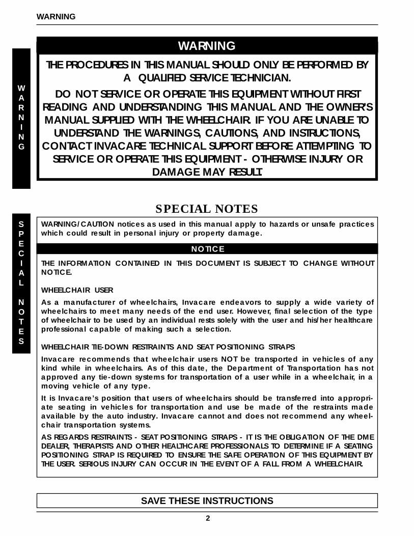
WARNINGTHE PROCEDURES IN THIS MANUAL SHOULD ONLY BE PERFORMED BY
A QUALIFIED SERVICE TECHNICIAN.DO NOT SERVICE OR OPERATE THIS EQUIPMENT WITHOUT FIRST
READING AND UNDERSTANDING THIS MANUAL AND THE OWNER’SMANUAL SUPPLIED WITH THE WHEELCHAIR. IF YOU ARE UNABLE TO
UNDERSTAND THE WARNINGS, CAUTIONS, AND INSTRUCTIONS,CONTACT INVACARE TECHNICAL SUPPORT BEFORE ATTEMPTING TO
SERVICE OR OPERATE THIS EQUIPMENT - OTHERWISE INJURY ORDAMAGE MAY RESULT.
SPECIAL NOTESWARNING/CAUTION notices as used in this manual apply to hazards or unsafe practiceswhich could result in personal injury or property damage.
NOTICE
THE INFORMATION CONTAINED IN THIS DOCUMENT IS SUBJECT TO CHANGE WITHOUTNOTICE.
WHEELCHAIR USER
As a manufacturer of wheelchairs, Invacare endeavors to supply a wide variety ofwheelchairs to meet many needs of the end user. However, final selection of the typeof wheelchair to be used by an individual rests solely with the user and his/her healthcareprofessional capable of making such a selection.
WHEELCHAIR TIE-DOWN RESTRAINTS AND SEAT POSITIONING STRAPS
Invacare recommends that wheelchair users NOT be transported in vehicles of anykind while in wheelchairs. As of this date, the Department of Transportation has notapproved any tie-down systems for transportation of a user while in a wheelchair, in amoving vehicle of any type.
It is Invacare’s position that users of wheelchairs should be transferred into appropri-ate seating in vehicles for transportation and use be made of the restraints madeavailable by the auto industry. Invacare cannot and does not recommend any wheel-chair transportation systems.
AS REGARDS RESTRAINTS - SEAT POSITIONING STRAPS - IT IS THE OBLIGATION OF THE DMEDEALER, THERAPISTS AND OTHER HEALTHCARE PROFESSIONALS TO DETERMINE IF A SEATINGPOSITIONING STRAP IS REQUIRED TO ENSURE THE SAFE OPERATION OF THIS EQUIPMENT BYTHE USER. SERIOUS INJURY CAN OCCUR IN THE EVENT OF A FALL FROM A WHEELCHAIR.
SPECIAL
NOTES

3
TABLE OF CONTENTS
TABLE
OF
CONTENTS
NOTE: The information in this owner's manual applies to the STORM ARROW, STORM TORQUE X, RANGERX, and the RECLINER Wheelchairs except where specified.
SPECIAL NOTES ................................................................................................................................... 2SPECIFICATIONS
FOR ARROW...................................................................................................................... .............. 5FOR TORQUE SP ........................................................................................................................... 6FOR RANGER X ................................................................................................................... ........... 7
PROCEDURE 1 - GENERAL GUIDELINES ........................................................................................... 8REPAIR OR SERVICE INFORMATION .............................................................................................. 8OPERATING INFORMATION ............................................................................................................. 8WARNING/CAUTION LABEL LOCATION ....................................................................................... 10
PROCEDURE 2 - TROUBLESHOOTING............................................................................................ 12FIELD LOAD TEST ......................................................................................................................... 12USING HYDROMETER TO CHECK BATTERY CELLS (LEAD ACID).............................................. 12MOTOR TESTING........................................................................................................................... 13MOTOR BRUSH INSPECTION ....................................................................................................... 14ELECTRO-MECHANICAL PARKING BRAKE TESTING................................................................... 14
PROCEDURE 3 - HARDWARE TORQUE SPECIFICATIONS .............................................................. 15STANDARD SEAT FRAME .............................................................................................................. 15CAPTAINS VAN SEAT...................................................................................................................... 16ADJUSTABLE SEAT FRAME ........................................................................................................... 16BASE FRAME HARDWARE TORQUE SPECIFICATIONS .............................................................. 17
PROCEDURE 4 - ARMS ....................................................................................................................... 18REPLACING ARMREST PADS - CAPTAINS VAN SEAT .................................................................. 18REPLACING CAPTAINS VAN SEAT ARMREST PLATE ................................................................... 18
PROCEDURE 5 - UPHOLSTERY/POSITIONING STRAP .................................................................. 19REPLACING SEAT POSITIONING STRAP - CAPTAINS VAN SEATS ............................................... 19REPLACING BACK UPHOLSTERY ................................................................................................ 19
PROCEDURE 6 - SEAT FRAME ........................................................................................................... 21PREPARATIONS FOR REMOVING/INSTALLING SEAT FRAME (STANDARD FRAME,ADJUSTABLE FRAME AND CAPTAINS VAN SEAT.......................................................................... 21REPLACING EXACT SAME SIZE STANDARD SEAT FRAME .......................................................... 22REMOVING/INSTALLING STANDARD SEAT FRAME SUB-ASSEMBLY ........................................... 22CHANGING SEAT DEPTH ............................................................................................................... 23CHANGING SEAT WIDTH (STANDARD AND ADJUSTABLE SEAT FRAME) ................................... 25INSTALLING/REMOVING ADJUSTABLE SEAT FRAME SUBASSEMBLY AND/OR COMPONENT REPLACEMENT ................................................................................................. 26INSTALLING/REMOVING CAPTAINS VAN SEAT ASSEMBLY ........................................................ 28REPLACING CAPTAINS VAN SEAT AND/OR CAPTAINS VAN SEAT FRAME .............................. 28CONVERTING FROM STANDARD SEAT FRAME TO ADJUSTABLE SEAT FRAME OR VICE VERSA............................................................................................................. .......... 29CONVERTING FROM ADJUSTABLE SEAT FRAME TO CAPTAINS VAN SEAT OR VICE VERSA............................................................................................................. .......... 29CONVERTING FROM STANDARD SEAT FRAME TO CAPTAINS VAN SEAT OR VICE VERSA............................................................................................................. .......... 30REMOVING/INSTALLING SEAT PAN .............................................................................................. 30MOUNTING PLATE - SEAT ANGLE ADJUSTMENT AND INSTALLATION ORIENTATION ............ 31
PROCEDURE 7 - BASE FRAME .......................................................................................................... 32REPLACING SEAT MOUNTING PLATES......................................................................................... 32REPLACING SEAT SUPPORT BRACKETS .................................................................................... 32REPLACING SEAT SUPPORT BRACKET T-NUTS ........................................................................ 33REPLACING BATTERY CHARGER BRACKET AND T-NUT............................................................ 34REMOVING/INSTALLING SEAT STOP SCREWS............................................................................ 34
PROCEDURE 8 - BACK FRAME .......................................................................................................... 35REPLACING CJ BACK BRACKETS ................................................................................................ 35CHANGING BACK HEIGHT ............................................................................................................. 36BACK ANGLE ADJUSTMENT.......................................................................................................... 38
TABLE OF CONTENTS

4
TABLE OF CONTENTS
TABLE OF CONTENTS (Continued)PROCEDURE 9 - BATTERIES ............................................................................................................. 39
INSTALLING/REMOVING BATTERIES INTO/FROM BATTERY BOX(ES) ......................................... 39DISCONNECTING/CONNETING BATTERY CABLES...................................................................... 40WHEN TO CHARGE BATTERIES ................................................................................................... 44CHARGING BATTERIES ................................................................................................................. 44REPLACING BATTERIES ................................................................................................................ 46REMOVING/INSTALLING GROUP 24 BATTERY BOXES FOR WHEELCHAIRS NOT EQUIPPED WITH VENT TRAY ..................................................................................................... 47REMOVING/INSTALLING GROUP 24 BATTERY BOXES FOR WHEELCHAIRS NOT EQUIPPED WITH VENT TRAY ..................................................................................................... 48INSTALLING/REMOVING BATTERY BOX - 22NF BATTERY BASE FRAME ..................................... 49
PROCEDURE 10 - WIRING HARNESS .................................................................................................. 50REMOVING/INSTALLING THE WIRING HARNESS............................................................................ 50ADJUSTING LIMIT SWITCH ............................................................................................................. 54
PROCEDURE 11 - RETENTION STRAP/RETAINER ......................................................................... 55REPLACING BATTERY BOX RETAINER/RETAINER CLIP - GROUP 24 BATTERY BASE FRAMES .. 55
PROCEDURE 12 - WHEELS/MOTORS ............................................................................................. 57REPLACING PNEUMATIC TIRES/TUBES - DRIVE WHEELS/CASTERS ........................................... 57REMOVING/INSTALLING DRIVE WHEELS......................................................................................... 57REMOVING/INSTALLING DRIVE WHEEL HUB ................................................................................... 58INSTALLING WHEEL LOCK BRACKET ONTO WHEEL CHAIR ......................................................... 58REMOVING/INSTALLING CASTERS .................................................................................................. 59REPLACING FORKS ......................................................................................................................... 59REMOVING/INSTALLING THE MOTOR (CONVENTIONAL MOTOR WITH GEARBOX) ...................... 60REMOVING/INSTALLING THE MOTOR (GEARLESS BRUSHLESS MOTOR) .................................... 61
PROCEDURE 13 - ELECTRONICS .................................................................................................... 66REPOSITIONING MKIV JOYSTICK - VAN SEAT MODELS .................................................................. 63REMOVING/INSTALLING MKIV CONTROLLER .................................................................................. 64
PROCEDURE 14 - RECLINER ........................................................................................................... 68POSITIONING LIMIT SWITCH ............................................................................................................ 68ADJUSTING LIMIT SWITCH ................................................................................................................ 68REPLACING RECLINER CABLE ASSEMBLIES ................................................................................. 69REPLACING/ADJUSTING GAS CYLINDERS ...................................................................................... 70CHANGING BACK HEIGHT ................................................................................................................ 71CHANGING SEAT DEPTH .................................................................................................................. 72CHANGING SEAT WIDTH .................................................................................................................. 72EQUIPMENT OPTION INSTALLING/REPLACING ADJUSTABLE 16 TO 19-INCH DEEP RECLINER SEAT FRAME ONTO ARROW OR X BASE FRAME.................................................... 73
PROCEDURE 16 - RWD WHEELCHAIRS ............................................................................................. 74REMOVING/INSTALLING GROUP 24 BATTERY BOX SUB-FRAME ........................................................ 74REMOVING/INSTALLING 22NF BATTERY BOX TRAY ............................................................................ 76EQUIPMENT OPTION CONVERTING 22NF BATTERY BOX TRAY TO GROUP 24 BATTERY BOX SUB FRAME ......................................................................................................................... 76SHOCK OR RUBBER ELEMENT REPLACEMENT FOR WHEELCHAIRS EQUIPPED WITH GROUP 24 BATTERIES....................................................................................... 79SHOCK OR RUBBER ELEMENT REPLACEMENT FOR WHEELCHAIRS EQUIPPED WITH 22NF BATTERIES .............................................................................................. 81SHOCK SPRING REPLACEMENT ....................................................................................................... 82REMOVING/INSTALLING GEARBOX .................................................................................................... 83ADJUSTING WEIGHT DISTRIBUTION .................................................................................................. 84REPOSITIONING MOTOR/GEARBOX ................................................................................................. 85REPOSITIONING THE GEARLESS/BRUSHLESS MOTOR ................................................................... 86REPLACING SUSPENSION ARM FOR WHEELCHAIRS WITH MOTOR/GEARBOX ASSEMBLY............. 87REPLACING THE SUSPENSION ARM FOR WHEELCHAIRS WITH GEARLESS/BRUSHLESS MOTOR. 88ANTI-TIPPER WHEEL REPLACEMENT ............................................................................................... 89REMOVING INSTALLING THE ANTI-TIP ASSEMBLY .............................................................................. 89
LIMITED WARRANTY ........................................................................................................................... 91
TABLE
OF
CONTENTS

5
SPECIFICATIONS
SPECIFICATIONS
SPECIFICATIONS
SPECIFICATIONS FOR ARROWSeat Width Range:Standard 12 to 24-inchesRecliner 14 to 24-inches
Seat Depth Range:Standard 12 to 22-inchesRecliner 14 to 22-inches
Back Height Range :Standard 12 to 24-inchesRecliner 18-1/2 to 26-inches
Seat-to-Floor (approximate)
Standard: 17-1/2 -inchesOptional: 19-3/4-inches
21-inchesOverall Width of Base : (w/o joystick) 25-inches
Overall Height
Standard: 34-1/4-inches
Minimum: 34-1/4-inches
Maximum: 44-1/4-inches
Recliner
Low Seat Frame: 51-1/2-inches
Med. Seat Frame: 53-3/4-inches
High Seat Frame: 55-1/2 inches
Overall Length(without front riggings)
Standard: 29-1/2-inches
Long Frame: 32-1/2-inches
Weight
Gearless/Brushless Motor
W/O GP24 Batteries: 174 lbs.
With GP24Batteries: 278 lbs.
Shipping (approx.): 214 lbs.
4 Pole Motor
Without Batteries: 162 lbs.
With Batteries: 266 lbs.
Shipping (approx.): 202 lbs.
u Non-Recliners ONLY.
Drive Axle: Adjustable
Drive Wheels/Tires:(Foam Filled or Pneumatic)
Standard: 14 X 3-inchesOptional: 14 X 4-inches
PHYSICAL DIMENSIONS
Casters w/PrecisionSealed Bearings
Semi-PneumaticStandard: 8 X 2-1/4-inchesOption: 6 X 2-inches (w/ shock fork)Pneumatic or Foam FilledStandard: 8 X 2-inchesOption: 9 X 2-3/4-inches
Anti-Tippers (3-inch wheels): Standard
Caster Forks: Standard, Shock Fork (Optional)
Footrests: Telescoping Front Rigging Supports, Swing-Away (Std), Heavy Duty (Opt.), 2-in. and 4-in. longer PivotSlide Tube (Opt)
Armrests: Flip Back, Fixed or Adjustable Height (Deskand Full Length)
Seat Angle Adjustment: Adjustable (0o to 10o)
Back Angle Adjustment: Adjustable (80o to 115o in 5o
increments)
Seat Cushion: Cushion (Optional)
Chair Upholstery Options: Naugahyde and Nylon
Battery requirements: See chart on page 46
Weight Limitations : Arrow with gearless/brushlessmotor - up to 300 lbs. Arrow with 4 pole motor - up to400 lbs.
Range will vary with battery conditions, surface, ter-rain and operators weight.
PERFORMANCE
RATING SPEED RANGE
G/B motor 4 Pole Motor300 lbs up to 8 mph N/A up to 29
400 lbs N/A up to 4.5 mph up to 19
Back Angle Range :Standard 80
o to 115
o
Recliner 90o to 170
o

6
SPECIFICATIONS
SPECIFICATIONS - TORQUE SPSeat Width Range:Standard 12 to 22-inchesRecliner 14 to 22-inches
Seat Depth Range:Standard 12 to 22-inchesRecliner 16 to 22-inches
Back Height Range :Standard 12 to 24-inchesRecliner 18-1/2 to 26-inches
Seat-to-Floor (approximate)
Standard: 17-1/2-inchesOptional: 19-3/4-inches
21-inchesOverall Width of Base : (w/o joystick) 25-inches
Overall Height
Standard: 34-1/4-inches
Minimum: 34-1/4-inches
Maximum: 44-1/4-inches
Recliner
Low Seat Frame: 51-1/2-inches
Med. Seat Frame: 53-3/4-inches
High Seat Frame: 55-1/2 inches
Overall Length(without front riggings)
Standard: 29-1/2-inches
Long Frame: 32-1/2-inches
u Non-Recliners ONLY.
Drive Axle: Adjustable
BATTERY REQUIREMENTS , WEIGHT LIMITATIONS, CHAIR WEIGHTWEIGHT CHAIR WEIGHT SHIPPING
MODEL MOTOR LIMITATION BATTERIES W/O BATT. W/ BATT. WEIGHTU250TQ 4 Pole Motor Up to 250 lbs *22NF 154 228 194 lbs
251-300TQ 4 Pole Motor 251-300 lbs *22 NF 154 228 194 lbs 251-300TQ Gearless/Brushless 251-300 lbs Group 24 166 270 206 lbs301-350TQ 4 Pole Motor 301-350 lbs Group 24 154 258 194 lbs
* Two batteries inside one battery box.
Range will vary with battery conditions, surface, ter-rain and operators weight.
PERFORMANCERATING SPEED RANGE
G/B motor 4 Pole Motor250 lbs N/A up to 4.5 mph up to 19
251-300 lbs up to 8 mph up to 29up to 4.5 mph up to 19
301-350 lbs N/A up to 4.5 mph up to 19
Drive Wheels/Tires:(Foam Filled or Pneumatic)
Standard: 14 X 3-inchesOptional: 14 X 4-inches
PHYSICAL DIMENSIONS
Casters w/PrecisionSealed Bearings
Semi-PneumaticStandard: 8 X 1-1/4-inOption: 6 X 2-in.(w/ shock fork) Pneumatic or Foam FilledStandard: 8 X 2-inchesOption: 9 X 2-3/4-inches
Anti-Tippers (3-inch wheels): Standard
Caster Forks: Standard, Shock Fork (Optional)
Footrests: Telescoping Front Rigg Supports, Swing-Away, Heavy Duty, 4-in. longer Pivot Slide Tube (Opt)
Armrests: Flip Back, Fixed or Adjustable Height (Deskand Full Length)
Seat Angle Adjustment: Adjustable (0o to 10o)
Back Angle Adjustment: Adjustable (80o to 115o in 5o
increments)
Seat Cushion: Cushion (Optional)
Chair Upholstery Options: Naugahyde and Nylon
SPECIFICATIONS - TORQUE SP
Back Angle Range :Standard 80
o to 115
o
Recliner 90o to 170
o
7
SPECIFICATIONS
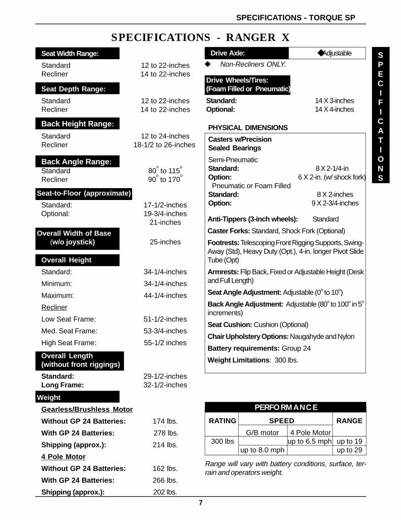
SPECIFICATIONS - RANGER XSeat Width Range:
Standard 12 to 22-inchesRecliner 14 to 22-inches
Seat Depth Range:
Standard 12 to 22-inchesRecliner 14 to 22-inches
Back Height Range :
Standard 12 to 24-inchesRecliner 18-1/2 to 26-inches
Seat-to-Floor (approximate)
Standard: 17-1/2-inchesOptional: 19-3/4-inches
21-inches
Overall Width of Base : (w/o joystick) 25-inches
Overall Height
Standard: 34-1/4-inches
Minimum: 34-1/4-inches
Maximum: 44-1/4-inches
Recliner
Low Seat Frame: 51-1/2-inches
Med. Seat Frame: 53-3/4-inches
High Seat Frame: 55-1/2 inches
Overall Length(without front riggings)
Standard: 29-1/2-inchesLong Frame: 32-1/2-inches
Weight
Gearless/Brushless Motor
Without GP 24 Batteries: 174 lbs.
With GP 24 Batteries: 278 lbs.
Shipping (approx.): 214 lbs.
4 Pole Motor
Without GP 24 Batteries: 162 lbs.
With GP 24 Batteries: 266 lbs.
Shipping (approx.): 202 lbs.
Drive Wheels/Tires:(Foam Filled or Pneumatic)
Standard: 14 X 3-inchesOptional: 14 X 4-inches
PHYSICAL DIMENSIONS
Casters w/PrecisionSealed Bearings
Semi-PneumaticStandard: 8 X 2-1/4-inOption: 6 X 2-in. (w/ shock fork) Pneumatic or Foam FilledStandard: 8 X 2-inchesOption: 9 X 2-3/4-inches
Anti-Tippers (3-inch wheels): Standard
Caster Forks: Standard, Shock Fork (Optional)
Footrests: Telescoping Front Rigging Supports, Swing-Away (Std), Heavy Duty (Opt.), 4-in. longer Pivot SlideTube (Opt)
Armrests: Flip Back, Fixed or Adjustable Height (Deskand Full Length)
Seat Angle Adjustment: Adjustable (0o to 10o)
Back Angle Adjustment: Adjustable (80o to 100o in 5o
increments)
Seat Cushion: Cushion (Optional)
Chair Upholstery Options: Naugahyde and Nylon
Battery requirements: Group 24
Weight Limitations : 300 lbs.
Range will vary with battery conditions, surface, ter-rain and operators weight.
PERFORMANCE
RATING SPEED RANGE
G/B motor 4 Pole Motor300 lbs up to 6.5 mph up to 19
up to 8.0 mph up to 29
Back Angle Range :Standard 80
o to 115
o
Recliner 90o to 170
o
Drive Axle: Adjustable
u Non-Recliners ONLY.
SPECIFICATIONS - TORQUE SP
8
GENERAL GUIDELINESPROCEDURE 1
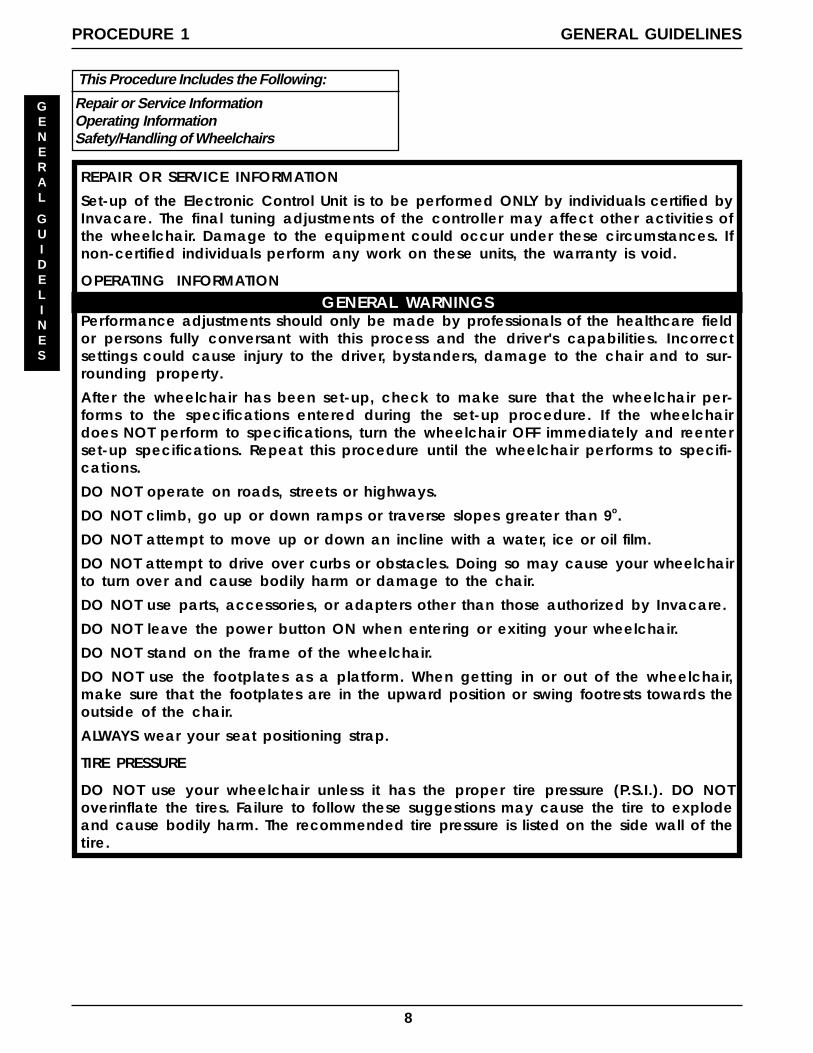
This Procedure Includes the Following:
Repair or Service InformationOperating InformationSafety/Handling of Wheelchairs
REPAIR OR SERVICE INFORMATION
Set-up of the Electronic Control Unit is to be performed ONLY by individuals certified byInvacare. The final tuning adjustments of the controller may affect other activities ofthe wheelchair. Damage to the equipment could occur under these circumstances. Ifnon-certified individuals perform any work on these units, the warranty is void.
OPERATING INFORMATIONGENERAL WARNINGS
Performance adjustments should only be made by professionals of the healthcare fieldor persons fully conversant with this process and the driver's capabilities. Incorrectsettings could cause injury to the driver, bystanders, damage to the chair and to sur-rounding property.
After the wheelchair has been set-up, check to make sure that the wheelchair per-forms to the specifications entered during the set-up procedure. If the wheelchairdoes NOT perform to specifications, turn the wheelchair OFF immediately and reenterset-up specifications. Repeat this procedure until the wheelchair performs to specifi-cations.
DO NOT operate on roads, streets or highways.
DO NOT climb, go up or down ramps or traverse slopes greater than 9o.
DO NOT attempt to move up or down an incline with a water, ice or oil film.
DO NOT attempt to drive over curbs or obstacles. Doing so may cause your wheelchairto turn over and cause bodily harm or damage to the chair.
DO NOT use parts, accessories, or adapters other than those authorized by Invacare.
DO NOT leave the power button ON when entering or exiting your wheelchair.
DO NOT stand on the frame of the wheelchair.
DO NOT use the footplates as a platform. When getting in or out of the wheelchair,make sure that the footplates are in the upward position or swing footrests towards theoutside of the chair.
ALWAYS wear your seat positioning strap.
TIRE PRESSURE
DO NOT use your wheelchair unless it has the proper tire pressure (P.S.I.). DO NOToverinflate the tires. Failure to follow these suggestions may cause the tire to explodeand cause bodily harm. The recommended tire pressure is listed on the side wall of thetire.
GENERAL
GUIDELINES
9
GENERAL GUIDELINES PROCEDURE 1
GENERAL
GUIDELINES
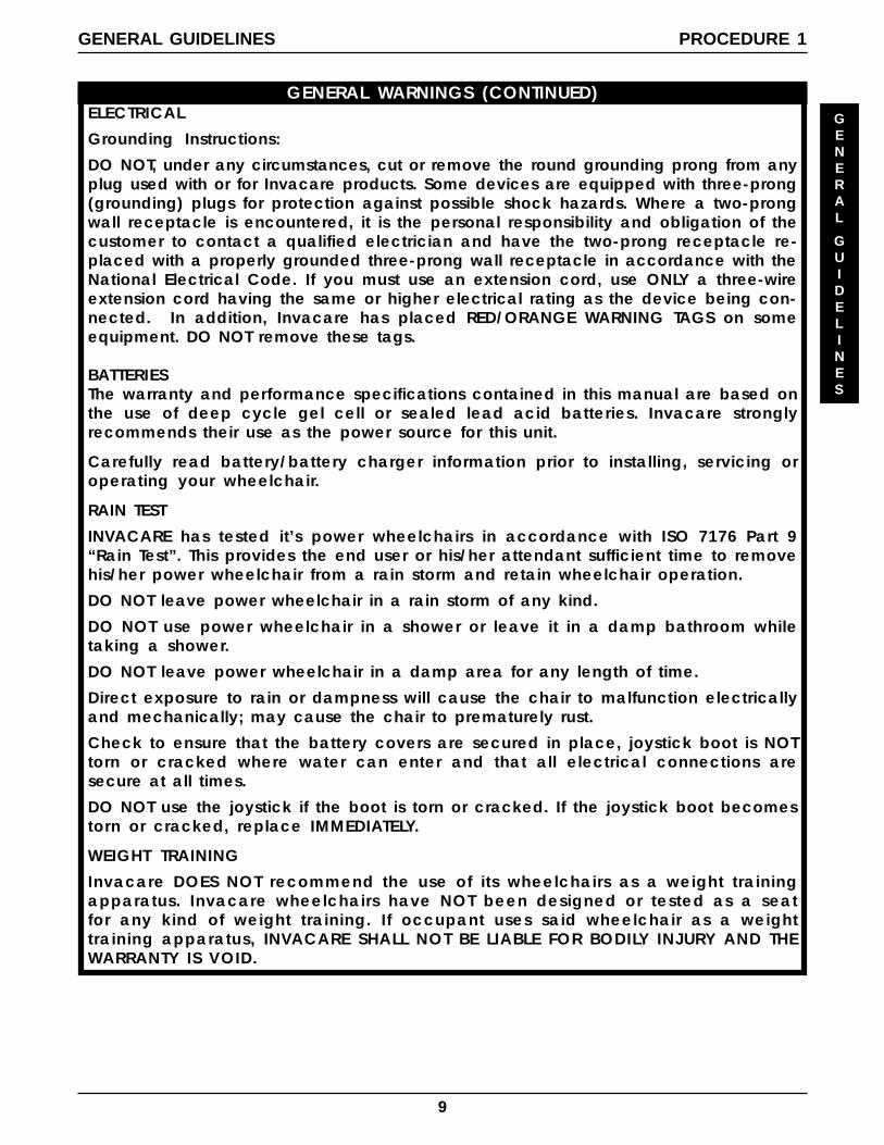
GENERAL WARNINGS (CONTINUED)ELECTRICAL
Grounding Instructions:
DO NOT, under any circumstances, cut or remove the round grounding prong from anyplug used with or for Invacare products. Some devices are equipped with three-prong(grounding) plugs for protection against possible shock hazards. Where a two-prongwall receptacle is encountered, it is the personal responsibility and obligation of thecustomer to contact a qualified electrician and have the two-prong receptacle re-placed with a properly grounded three-prong wall receptacle in accordance with theNational Electrical Code. If you must use an extension cord, use ONLY a three-wireextension cord having the same or higher electrical rating as the device being con-nected. In addition, Invacare has placed RED/ORANGE WARNING TAGS on someequipment. DO NOT remove these tags.
BATTERIESThe warranty and performance specifications contained in this manual are based onthe use of deep cycle gel cell or sealed lead acid batteries. Invacare stronglyrecommends their use as the power source for this unit.
Carefully read battery/battery charger information prior to installing, servicing oroperating your wheelchair.
RAIN TEST
INVACARE has tested it’s power wheelchairs in accordance with ISO 7176 Part 9“Rain Test”. This provides the end user or his/her attendant sufficient time to removehis/her power wheelchair from a rain storm and retain wheelchair operation.
DO NOT leave power wheelchair in a rain storm of any kind.
DO NOT use power wheelchair in a shower or leave it in a damp bathroom whiletaking a shower.
DO NOT leave power wheelchair in a damp area for any length of time.
Direct exposure to rain or dampness will cause the chair to malfunction electricallyand mechanically; may cause the chair to prematurely rust.
Check to ensure that the battery covers are secured in place, joystick boot is NOTtorn or cracked where water can enter and that all electrical connections aresecure at all times.
DO NOT use the joystick if the boot is torn or cracked. If the joystick boot becomestorn or cracked, replace IMMEDIATELY.
WEIGHT TRAINING
Invacare DOES NOT recommend the use of its wheelchairs as a weight trainingapparatus. Invacare wheelchairs have NOT been designed or tested as a seatfor any kind of weight training. If occupant uses said wheelchair as a weighttraining apparatus, INVACARE SHALL NOT BE LIABLE FOR BODILY INJURY AND THEWARRANTY IS VOID.
10
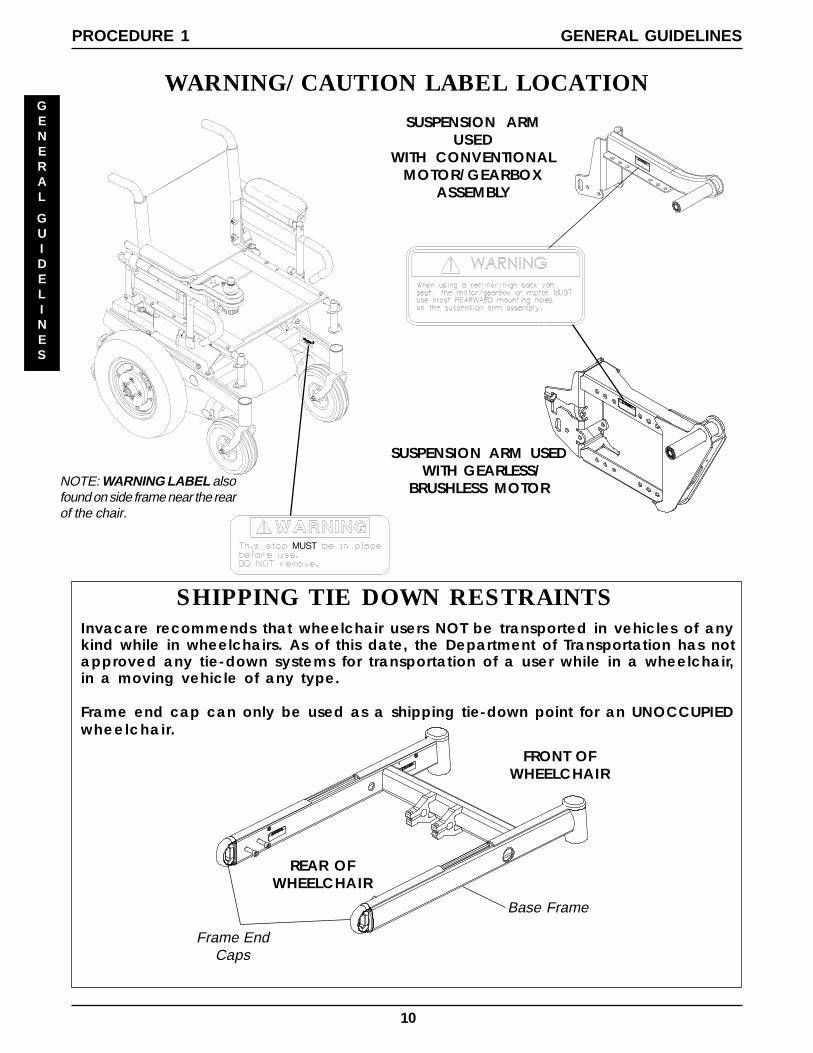
SUSPENSION ARM USED WITH GEARLESS/
BRUSHLESS MOTOR
SUSPENSION ARMUSED
WITH CONVENTIONALMOTOR/GEARBOX
ASSEMBLY
1070497
MUST
SHIPPING TIE DOWN RESTRAINTS
GENERAL
GUIDELINES
Invacare recommends that wheelchair users NOT be transported in vehicles of anykind while in wheelchairs. As of this date, the Department of Transportation has notapproved any tie-down systems for transportation of a user while in a wheelchair,in a moving vehicle of any type.
Frame end cap can only be used as a shipping tie-down point for an UNOCCUPIEDwheelchair.
Base Frame
Frame EndCaps
WARNING/CAUTION LABEL LOCATION
REAR OFWHEELCHAIR
FRONT OFWHEELCHAIR
NOTE: WARNING LABEL alsofound on side frame near the rearof the chair.
GENERAL GUIDELINESPROCEDURE 1
11
GENERAL GUIDELINES PROCEDURE 1
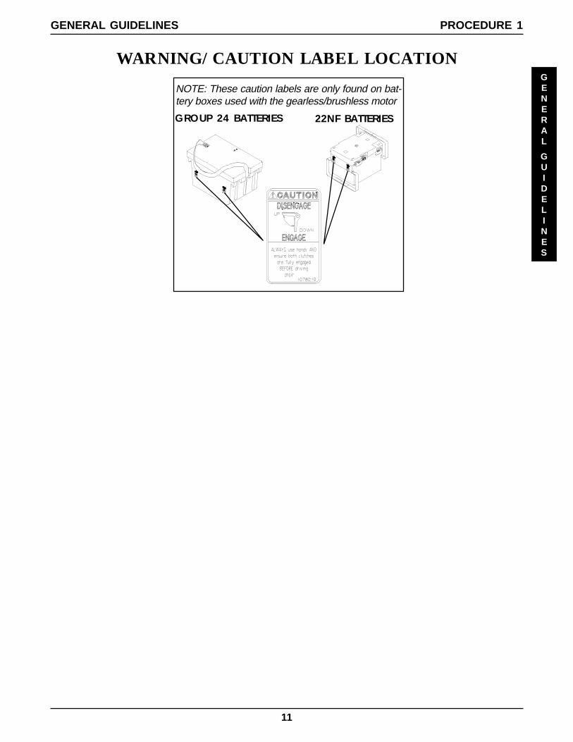
NOTE: These caution labels are only found on bat-tery boxes used with the gearless/brushless motor
GROUP 24 BATTERIES 22NF BATTERIES
WARNING/CAUTION LABEL LOCATIONGENERAL
GUIDELINES
12
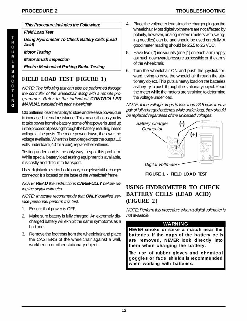
FIELD LOAD TEST (FIGURE 1)
NOTE: The following test can also be performed throughthe controller of the wheelchair along with a remote pro-grammer. Refer to the individual CONTROLLERMANUAL supplied with each wheelchair.
Old batteries lose their ability to store and release power, dueto increased internal resistance. This means that as you tryto take power from the battery, some of that power is used upin the process of passing through the battery, resulting in lessvoltage at the posts. The more power drawn, the lower thevoltage available. When this lost voltage drops the output 1.0volts under load (2.0 for a pair), replace the batteries.
Testing under load is the only way to spot this problem.While special battery load testing equipment is available,it is costly and difficult to transport.
Use a digital voltmeter to check battery charge level at the chargerconnector. It is located on the base of the wheelchair frame.
NOTE: READ the instructions CAREFULLY before us-ing the digital voltmeter.
NOTE: Invacare recommends that ONLY qualified ser-vice personnel perform this test.
1. Ensure that power is OFF.
2. Make sure battery is fully charged. An extremely dis-charged battery will exhibit the same symptoms as abad one.
3. Remove the footrests from the wheelchair and placethe CASTERS of the wheelchair against a wall,workbench or other stationary object.
(+)
(-)
FIGURE 1 - FIELD LOAD TEST
Battery ChargerConnector
Digital Voltmeter
USING HYDROMETER TO CHECKBATTERY CELLS (LEAD ACID)(FIGURE 2)
NOTE: Perform this procedure when a digital voltmeter isnot available.
WARNINGNEVER smoke or strike a match near thebatteries. If the caps of the battery cellsare removed, NEVER look directly intothem when charging the battery.
The use of rubber gloves and chemicalgoggles or face shields is recommendedwhen working with batteries.
PROCEDURE 2
4. Place the voltmeter leads into the charger plug on thewheelchair. Most digital voltmeters are not affected bypolarity, however, analog meters (meters with swing-ing needles) can be and should be used carefully. Agood meter reading should be 25.5 to 26 VDC.
5. Have two (2) individuals (one [1] on each arm) applyas much downward pressure as possible on the armsof the wheelchair.
6. Turn the wheelchair ON and push the joystick for-ward, trying to drive the wheelchair through the sta-tionary object. This puts a heavy load on the batteriesas they try to push through the stationary object. Readthe meter while the motors are straining to determinethe voltage under load.
NOTE: If the voltage drops to less than 23.5 volts from apair of fully charged batteries while under load, they shouldbe replaced regardless of the unloaded voltages.
TROUBLESHOOTING
TROUBLESHOOTING
This Procedure Includes the Following:
Field Load Test
Using Hydrometer To Check Battery Cells (LeadAcid)
Motor Testing
Motor Brush Inspection
Electro-Mechanical Parking Brake Testing
13
TROUBLESHOOTING
PROCEDURE 2
TROUBLESHOOTING
WARNINGWhen reading a hydrometer, DO NOT al-low any liquid to come in contact withyour eyes or skin. It is a form of acid andcan cause serious burns, and in somecases, blindness. If you do get battery acidon you, flush the exposed areas with coolwater IMMEDIATELY. If the acid comes intocontact with eyes or causes serious burns,get medical help IMMEDIATELY.
The battery acid can damage your wheel-chair, clothing, and household items.Therefore, take readings cautiously andonly in designated areas.
ONLY use distilled water when topping offthe battery cells.
Most batteries are not sold with instructions.However, warnings are frequently notedon the cell caps. Read them carefully.
1. Remove the battery box(es). Refer to INSTALLING/REMOVING BATTERY BOXES - GROUP 24 BAT-TERY BASE FRAMES or INSTALLING/REMOVINGBATTERY BOX - 22NF BATTERY BASE FRAMESin PROCEDURE 9 of this manual.
2. Remove the battery caps from the battery.
3. Squeeze the air from the hydrometer.
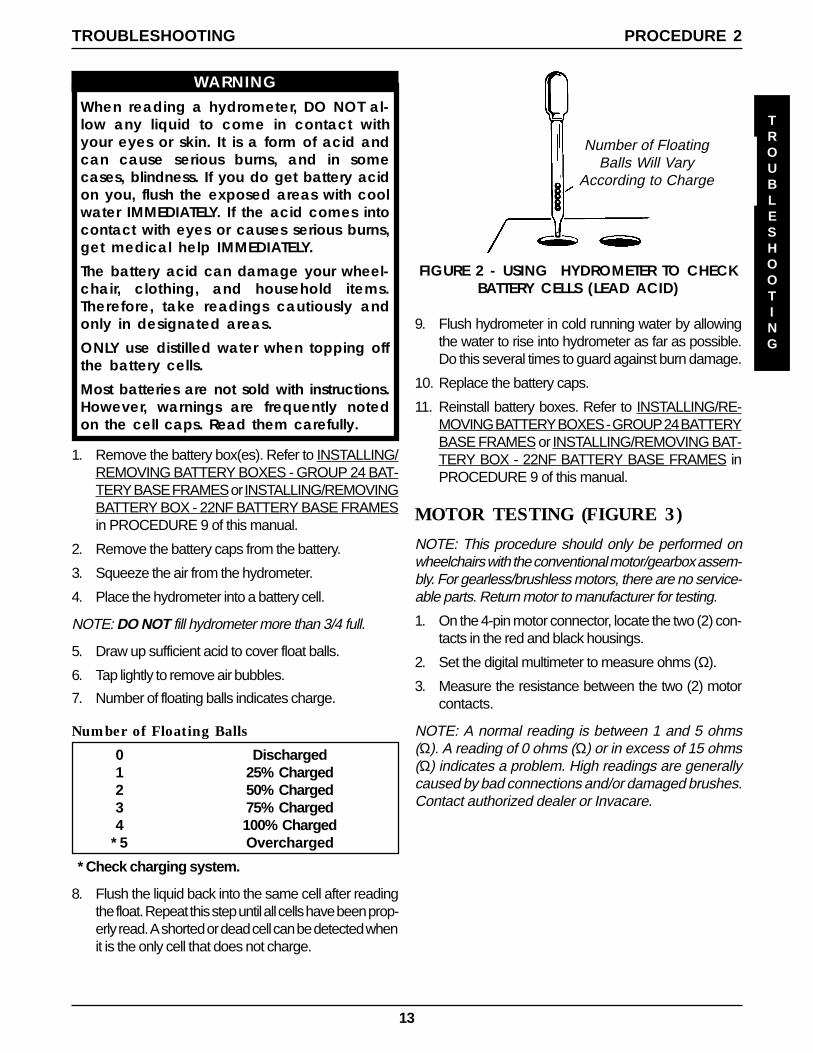
4. Place the hydrometer into a battery cell.
NOTE: DO NOT fill hydrometer more than 3/4 full.
5. Draw up sufficient acid to cover float balls.
6. Tap lightly to remove air bubbles.
7. Number of floating balls indicates charge.
Number of Floating Balls
0 Discharged1 25% Charged2 50% Charged3 75% Charged4 100% Charged
* 5 Overcharged
* Check charging system.
8. Flush the liquid back into the same cell after readingthe float. Repeat this step until all cells have been prop-erly read. A shorted or dead cell can be detected whenit is the only cell that does not charge.
FIGURE 2 - USING HYDROMETER TO CHECKBATTERY CELLS (LEAD ACID)
Number of FloatingBalls Will Vary
According to Charge
9. Flush hydrometer in cold running water by allowingthe water to rise into hydrometer as far as possible.Do this several times to guard against burn damage.
10. Replace the battery caps.
11. Reinstall battery boxes. Refer to INSTALLING/RE-MOVING BATTERY BOXES - GROUP 24 BATTERYBASE FRAMES or INSTALLING/REMOVING BAT-TERY BOX - 22NF BATTERY BASE FRAMES inPROCEDURE 9 of this manual.
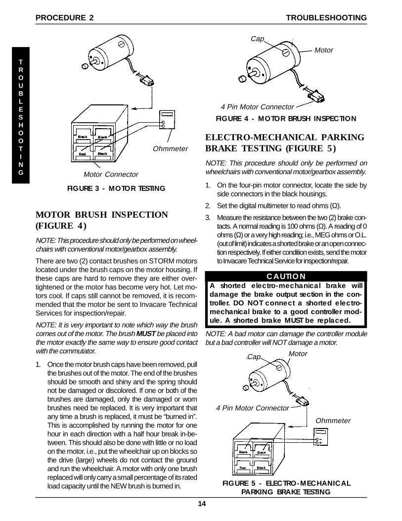
MOTOR TESTING (FIGURE 3)
NOTE: This procedure should only be performed onwheelchairs with the conventional motor/gearbox assem-bly. For gearless/brushless motors, there are no service-able parts. Return motor to manufacturer for testing.
1. On the 4-pin motor connector, locate the two (2) con-tacts in the red and black housings.
2. Set the digital multimeter to measure ohms (Ω).
3. Measure the resistance between the two (2) motorcontacts.
NOTE: A normal reading is between 1 and 5 ohms(Ω). A reading of 0 ohms (Ω) or in excess of 15 ohms(Ω) indicates a problem. High readings are generallycaused by bad connections and/or damaged brushes.Contact authorized dealer or Invacare.
TROUBLESHOOTING
14
ELECTRO-MECHANICAL PARKINGBRAKE TESTING (FIGURE 5)
NOTE: This procedure should only be performed onwheelchairs with conventional motor/gearbox assembly.
1. On the four-pin motor connector, locate the side byside connectors in the black housings.
2. Set the digital multimeter to read ohms (Ω).
3. Measure the resistance between the two (2) brake con-tacts. A normal reading is 100 ohms (Ω). A reading of 0ohms (Ω) or a very high reading; i.e., MEG ohms or O.L.(out of limit) indicates a shorted brake or an open connec-tion respectively. If either condition exists, send the motorto Invacare Technical Service for inspection/repair.
CAUTIONA shorted electro-mechanical brake willdamage the brake output section in the con-troller. DO NOT connect a shorted electro-mechanical brake to a good controller mod-ule. A shorted brake MUST be replaced.
NOTE: A bad motor can damage the controller modulebut a bad controller will NOT damage a motor.
4 Pin Motor Connector
Ohmmeter
Cap Motor
Cap
4 Pin Motor Connector
Motor
FIGURE 5 - ELECTRO-MECHANICALPARKING BRAKE TESTING
MOTOR BRUSH INSPECTION(FIGURE 4)
NOTE: This procedure should only be performed on wheel-chairs with conventional motor/gearbox assembly.
There are two (2) contact brushes on STORM motorslocated under the brush caps on the motor housing. Ifthese caps are hard to remove they are either over-tightened or the motor has become very hot. Let mo-tors cool. If caps still cannot be removed, it is recom-mended that the motor be sent to Invacare TechnicalServices for inspection/repair.
NOTE: It is very important to note which way the brushcomes out of the motor. The brush MUST be placed intothe motor exactly the same way to ensure good contactwith the commutator.
1. Once the motor brush caps have been removed, pullthe brushes out of the motor. The end of the brushesshould be smooth and shiny and the spring shouldnot be damaged or discolored. If one or both of thebrushes are damaged, only the damaged or wornbrushes need be replaced. It is very important thatany time a brush is replaced, it must be “burned in”.This is accomplished by running the motor for onehour in each direction with a half hour break in-be-tween. This should also be done with little or no loadon the motor, i.e., put the wheelchair up on blocks sothe drive (large) wheels do not contact the groundand run the wheelchair. A motor with only one brushreplaced will only carry a small percentage of its ratedload capacity until the NEW brush is burned in.
FIGURE 4 - MOTOR BRUSH INSPECTION
TROUBLESHOOTING
TROUBLESHOOTINGPROCEDURE 2
FIGURE 3 - MOTOR TESTING
Motor Connector
Ohmmeter
Motor Connector
Ohmmeter
15
PROCEDURE 3HARDWARE TORQUE SPECIFICATIONS
TORQUE
SPECIFICATIONS
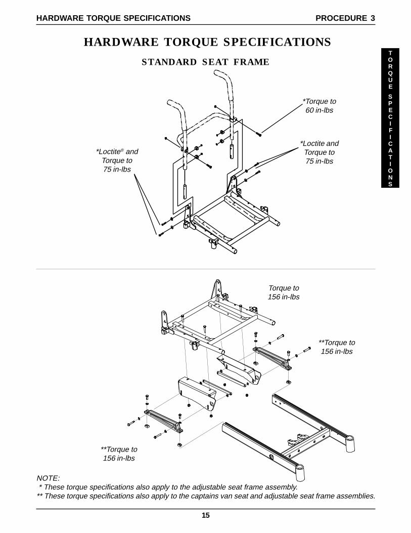
HARDWARE TORQUE SPECIFICATIONS
*Torque to60 in-lbs
Torque to156 in-lbs
**Torque to156 in-lbs
STANDARD SEAT FRAME
*Loctite® andTorque to75 in-lbs
*Loctite andTorque to75 in-lbs
**Torque to156 in-lbs
NOTE: * These torque specifications also apply to the adjustable seat frame assembly.** These torque specifications also apply to the captains van seat and adjustable seat frame assemblies.
16
TORQUE
SPECIFICATIONS
PROCEDURE 3 HARDWARE TORQUE SPECIFICATIONS
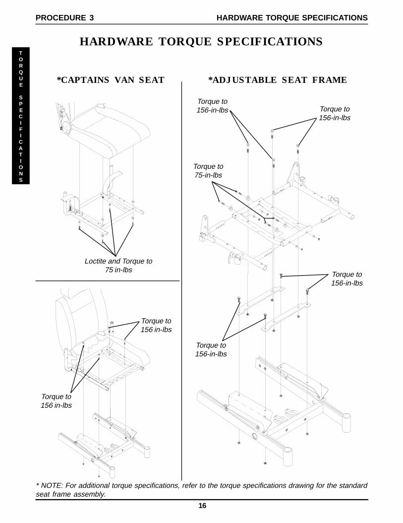
Torque to75-in-lbs
HARDWARE TORQUE SPECIFICATIONS
*CAPTAINS VAN SEAT
Loctite and Torque to75 in-lbs
Torque to156 in-lbs
*ADJUSTABLE SEAT FRAME
Torque to156 in-lbs
Torque to156-in-lbs Torque to
156-in-lbs
Torque to156-in-lbs
Torque to156-in-lbs
* NOTE: For additional torque specifications, refer to the torque specifications drawing for the standardseat frame assembly.
17
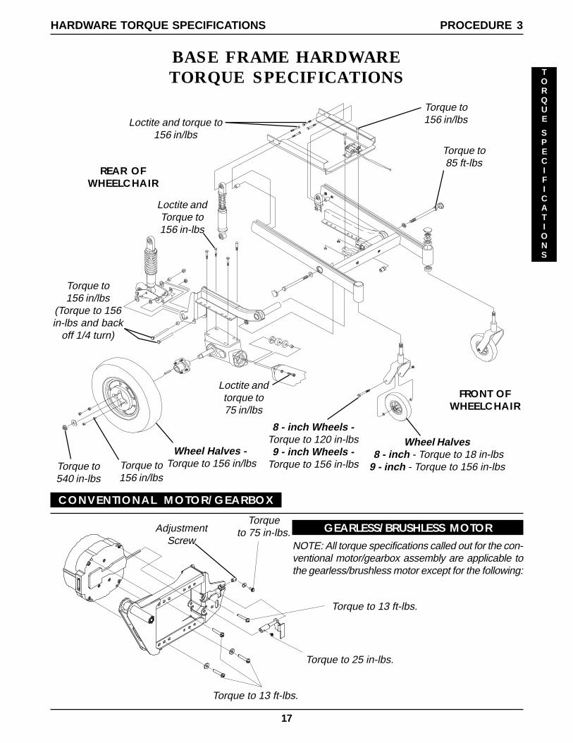
AdjustmentScrew
Torque to156 in/lbsLoctite and torque to
156 in/lbs
Torque to85 ft-lbs
8 - inch Wheels -Torque to 120 in-lbs9 - inch Wheels -
Torque to 156 in-lbs
Torque to156 in/lbs
(Torque to 156in-lbs and back
off 1/4 turn)
Loctite andtorque to75 in/lbs
Wheel Halves 8 - inch - Torque to 18 in-lbs9 - inch - Torque to 156 in-lbs
Loctite andTorque to156 in-lbs
Torque to156 in/lbs
Torque to540 in-lbs
Wheel Halves - Torque to 156 in/lbs
FRONT OFWHEELCHAIR
REAR OFWHEELCHAIR
PROCEDURE 3HARDWARE TORQUE SPECIFICATIONS
TORQUE
SPECIFICATIONS
BASE FRAME HARDWARETORQUE SPECIFICATIONS
GEARLESS/BRUSHLESS MOTOR
Torque to 13 ft-lbs.
Torque to 13 ft-lbs.
Torque to 25 in-lbs.
Torqueto 75 in-lbs.
CONVENTIONAL MOTOR/GEARBOX
NOTE: All torque specifications called out for the con-ventional motor/gearbox assembly are applicable tothe gearless/brushless motor except for the following:
18
ARMS
ARMSPROCEDURE 4
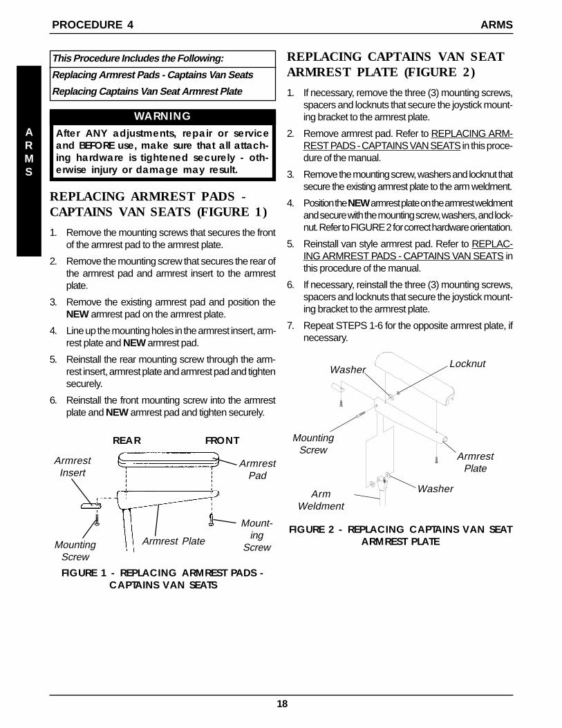
REPLACING ARMREST PADS -CAPTAINS VAN SEATS (FIGURE 1)
1. Remove the mounting screws that secures the frontof the armrest pad to the armrest plate.
2. Remove the mounting screw that secures the rear ofthe armrest pad and armrest insert to the armrestplate.
3. Remove the existing armrest pad and position theNEW armrest pad on the armrest plate.
4. Line up the mounting holes in the armrest insert, arm-rest plate and NEW armrest pad.
5. Reinstall the rear mounting screw through the arm-rest insert, armrest plate and armrest pad and tightensecurely.
6. Reinstall the front mounting screw into the armrestplate and NEW armrest pad and tighten securely.
ArmrestInsert
Mount-ing
Screw
ArmrestPad
Armrest Plate
FIGURE 1 - REPLACING ARMREST PADS -CAPTAINS VAN SEATS
MountingScrew
REPLACING CAPTAINS VAN SEATARMREST PLATE (FIGURE 2)
1. If necessary, remove the three (3) mounting screws,spacers and locknuts that secure the joystick mount-ing bracket to the armrest plate.
2. Remove armrest pad. Refer to REPLACING ARM-REST PADS - CAPTAINS VAN SEATS in this proce-dure of the manual.
3. Remove the mounting screw, washers and locknut thatsecure the existing armrest plate to the arm weldment.
4. Position the NEW armrest plate on the armrest weldmentand secure with the mounting screw, washers, and lock-nut. Refer to FIGURE 2 for correct hardware orientation.
5. Reinstall van style armrest pad. Refer to REPLAC-ING ARMREST PADS - CAPTAINS VAN SEATS inthis procedure of the manual.
6. If necessary, reinstall the three (3) mounting screws,spacers and locknuts that secure the joystick mount-ing bracket to the armrest plate.
7. Repeat STEPS 1-6 for the opposite armrest plate, ifnecessary.
MountingScrew
Washer Locknut
Washer
FIGURE 2 - REPLACING CAPTAINS VAN SEATARMREST PLATE
ArmWeldment
ArmrestPlate
FRONTREAR
This Procedure Includes the Following:
Replacing Armrest Pads - Captains Van Seats
Replacing Captains Van Seat Armrest Plate
WARNINGAfter ANY adjustments, repair or serviceand BEFORE use, make sure that all attach-ing hardware is tightened securely - oth-erwise injury or damage may result.
19
UPHOLSTERY/POSITIONING STRAP PROCEDURE 5
UPHOLSTERY
POSITIONING
STRAP
This Procedure Includes the Following:
Replacing Seat Positioning Strap - Captains VanSeats
Replacing Back Upholstery
WARNINGAfter ANY adjustments, repair or serviceand BEFORE use, make sure that all attach-ing hardware is tightened securely - oth-erwise injury or damage may result.
FIGURE 1 - REPLACING SEAT POSITIONINGSTRAP - CAPTAINS VAN SEATS
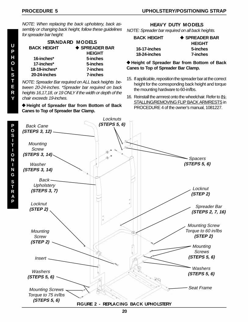
REPLACING BACK UPHOLSTERY(FIGURE 2)
1. Remove one (1) armrest from the wheelchair. Refer toINSTALLING/REMOVING FLIP BACK ARMRESTS inPROCEDURE 4 of the owner’s manual, 1081227.
2. If applicable, remove the two (2) mounting screwsand locknuts that secure the spreader bar to the backcanes.
3. Remove the two (2) mounting screws and washersthat secure the existing back upholstery to the backcanes.
4. Cut the tie-wraps that secure the bottom of the exist-ing back upholstery to the back canes.
NOTE: Note the back angle before disassembly for properreinstallation.
5. On the side of the wheelchair that the armrest wasremoved, remove one (1) of the mounting screws,washer, spacer, and locknut that secures the backcane to the seat frame.
NOTE: To avoid losing the insert in each back cane, threadthe mounting screw just removed through the cane fromthe inside of the wheelchair to hold the insert in place.
6. Remove the other mounting screw, washer, spacer,and locknut that secures the back cane to the seatframe.
7. Slide the back cane out of the spreader bar (If appli-cable) and the existing back upholstery.
8. Remove other armrest from the chair. Refer to IN-STALLING/REMOVING FLIP BACK ARMRESTS inPROCEDURE 4 of the owner’s manual, 1081227.
9. Repeat STEPS 5-7 for the opposite side of the wheel-chair.
10. Slide the other back cane out of the spreader bar (ifapplicable) and the existing back upholstery.
11. Slide one(1) back cane into NEW back upholsteryand through spreader bar (if applicable).
12. Secure back cane to the seat frame from the outsideof the wheelchair with the existing two (2) mountingscrews, washers, spacers, and locknuts. Use Loctite242 and torque to 75-in/lbs.
13. Repeat STEPS 11-12 for opposite back cane.
14. Secure the top of the NEW back upholstery to theback canes with the two (2) existing mounting screws.
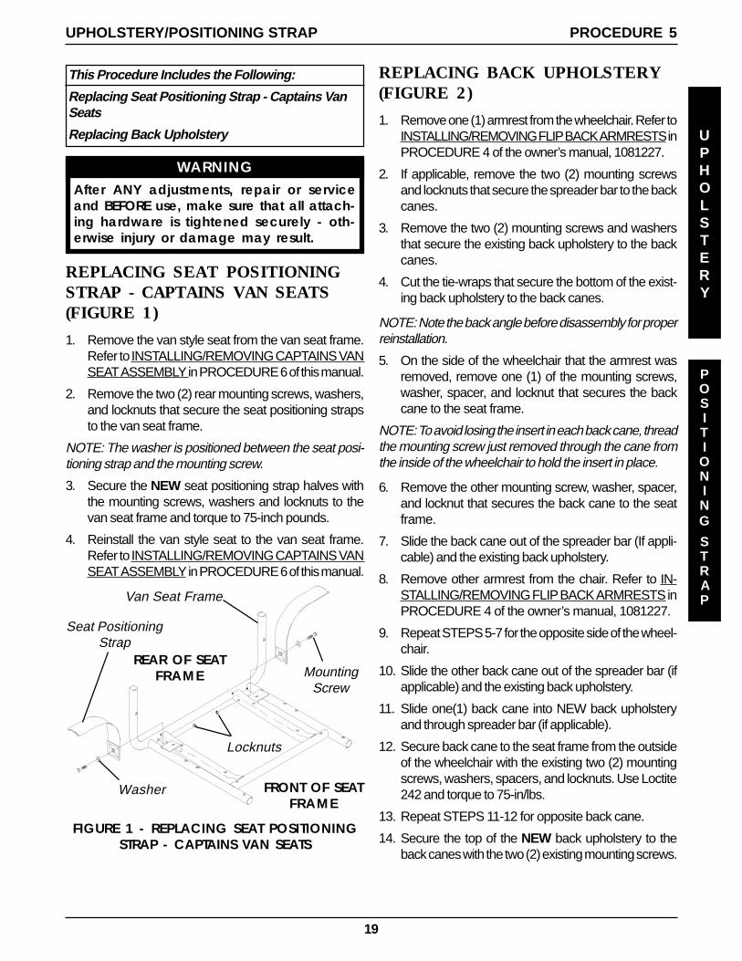
Van Seat Frame
Seat PositioningStrap
Locknuts
Washer FRONT OF SEATFRAME
REAR OF SEATFRAME Mounting
Screw
REPLACING SEAT POSITIONINGSTRAP - CAPTAINS VAN SEATS(FIGURE 1)
1. Remove the van style seat from the van seat frame.Refer to INSTALLING/REMOVING CAPTAINS VANSEAT ASSEMBLY in PROCEDURE 6 of this manual.
2. Remove the two (2) rear mounting screws, washers,and locknuts that secure the seat positioning strapsto the van seat frame.
NOTE: The washer is positioned between the seat posi-tioning strap and the mounting screw.
3. Secure the NEW seat positioning strap halves withthe mounting screws, washers and locknuts to thevan seat frame and torque to 75-inch pounds.
4. Reinstall the van style seat to the van seat frame.Refer to INSTALLING/REMOVING CAPTAINS VANSEAT ASSEMBLY in PROCEDURE 6 of this manual.
20
FIGURE 2 - REPLACING BACK UPHOLSTERY
Locknut(STEP 2)
MountingScrew
(STEP 2)
Locknut(STEP 2)
Mounting ScrewTorque to 60 in/lbs
(STEP 2)
Spreader Bar(STEPS 2, 7, 16)
MountingScrew
(STEPS 3, 14)
Washer(STEPS 3, 14)
BackUpholstery
(STEPS 3, 7)
Back Cane(STEPS 3, 12)
Insert
Seat FrameMounting ScrewsTorque to 75 in/lbs
(STEPS 5, 6)
Washers(STEPS 5, 6)
MountingScrews
(STEPS 5, 6)
Washers(STEPS 5, 6)
Spacers(STEPS 5, 6)
Locknuts(STEPS 5, 6)
HEAVY DUTY MODELSNOTE: Spreader bar required on all back heights.
BACK HEIGHT u SPREADER BARHEIGHT
16-17-inches 5-inches18-24-inches 7-inches
uHeight of Spreader Bar from Bottom of BackCanes to Top of Spreader Bar Clamp.
15. If applicable, reposition the spreader bar at the correctheight for the corresponding back height and torquethe mounting hardware to 60-in/lbs.
16. Reinstall the armrest onto the wheelchair. Refer to IN-STALLING/REMOVING FLIP BACK ARMRESTS inPROCEDURE 4 of the owner’s manual, 1081227.
NOTE: When replacing the back upholstery, back as-sembly or changing back height, follow these guidelinesfor spreader bar height:
STANDARD MODELSBACK HEIGHT u SPREADER BAR
HEIGHT16-inches* 5-inches17-inches* 5-inches
18-19-inches* 7-inches20-24-inches 7-inches
NOTE: Spreader Bar required on ALL back heights be-tween 20-24-inches. *Spreader bar required on backheights 16,17,18, or 19 ONLY if the width or depth of thechair exceeds 19-inches.
uHeight of Spreader Bar from Bottom of BackCanes to Top of Spreader Bar Clamp.
UPHOLSTERY/POSITIONING STRAPPROCEDURE 5
UPHOLSTERY
POSITIONING
STRAP
21
PROCEDURE 6SEAT FRAME
SEAT
FRAME
This Procedure includes the following:
Preparation for Removing/Installing Seat Frame(Standard Frame, Adjustable Frame,and Captains Van Seat) ............................Page 21
Replacing Exact Same Size StandardSeat Frame ..............................................Page 22
Removing/Installing Standard Seat FrameSub-Assembly .........................................Page 22
Changing Seat Depth ...............................Page 23
Changing Seat Width (Standard and AdjustableSeat Frame) .............................................Page 25
Installing/Removing Adjustable Seat FrameSub-Assembly and/or ComponentReplacement ...........................................Page 26
Installing/Removing Captains Van SeatAssembly ................................................Page 28
Replacing Captains Van Seat and/or CaptainsVan Seat Frame .......................................Page 28
Converting From Standard Seat Frame to Adjust-able Seat Frame or Vice Versa ..................Page 29
Converting From Adjustable Seat Frame toCaptains Van Seat or Vice Versa ...............Page 29
Converting From Standard Seat Frame to Cap-tains Van Seat or Vice Versa .....................Page 30
Removing/Installing Seat Pan ..................Page 30
Mounting Plate - Seat Angle Adjustment andInstallation Orientation .............................Page 31
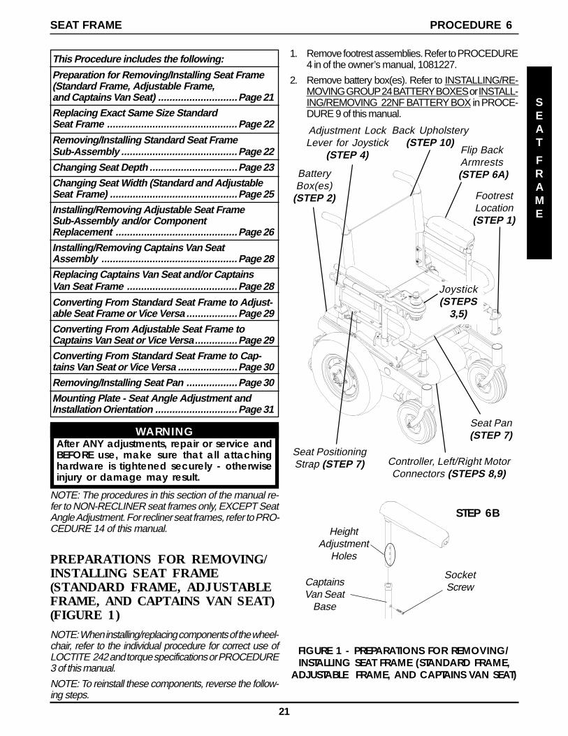
PREPARATIONS FOR REMOVING/INSTALLING SEAT FRAME(STANDARD FRAME, ADJUSTABLEFRAME, AND CAPTAINS VAN SEAT)(FIGURE 1)NOTE: When installing/replacing components of the wheel-chair, refer to the individual procedure for correct use ofLOCTITE 242 and torque specifications or PROCEDURE3 of this manual.
NOTE: To reinstall these components, reverse the follow-ing steps.
FIGURE 1 - PREPARATIONS FOR REMOVING/INSTALLING SEAT FRAME (STANDARD FRAME,
ADJUSTABLE FRAME, AND CAPTAINS VAN SEAT)
FootrestLocation(STEP 1)
BatteryBox(es)
(STEP 2)
Adjustment LockLever for Joystick
(STEP 4)
Joystick(STEPS
3,5)
Flip BackArmrests
(STEP 6A)
Seat Pan(STEP 7)
Controller, Left/Right MotorConnectors (STEPS 8,9)
Back Upholstery(STEP 10)
Seat PositioningStrap (STEP 7)
SocketScrewCaptains
Van SeatBase
HeightAdjustment
Holes
STEP 6B
1. Remove footrest assemblies. Refer to PROCEDURE4 in of the owner’s manual, 1081227.
2. Remove battery box(es). Refer to INSTALLING/RE-MOVING GROUP 24 BATTERY BOXES or INSTALL-ING/REMOVING 22NF BATTERY BOX in PROCE-DURE 9 of this manual.
WARNINGAfter ANY adjustments, repair or service andBEFORE use, make sure that all attachinghardware is tightened securely - otherwiseinjury or damage may result.
NOTE: The procedures in this section of the manual re-fer to NON-RECLINER seat frames only, EXCEPT SeatAngle Adjustment. For recliner seat frames, refer to PRO-CEDURE 14 of this manual.
22
3. Cut tie wraps and disconnect joystick from controller.
4. Turn the lever on the adjustment lock to release theadjustment lock from the joystick mounting tube.
5. Remove the joystick from the wheelchair.
6. Perform one (1) of the following:
A. STANDARD OR ADJUSTABLE SEATFRAMES - Remove the flip-back armrests fromthe wheelchair. Refer to INSTALLING/REMOVINGFLIP BACK ARMRESTS in PROCEDURE 4 ofthe owner’s manual, 1081227.
B. CAPTAINS VAN SEAT - Remove the mountingscrew that secures the armrest to the van seatframe. Repeat for opposite side.
7. For standard and adjustable seat frames, remove theseat pan (including seat positioning straps). Refer toREMOVING/INSTALLING SEAT PAN in this procedureof the manual.
8. Disconnect battery and left/right motor connectors fromthe controller. Refer to REPLACING WIRING HAR-NESS in PROCEDURE 10 of this manual.
9. Remove tie-wraps that secures the wiring harness tothe seat frame and the charger cable from its mount-ing bracket. Refer to REPLACING WIRING HARNESSin PROCEDURE 10 of this manual.
10. For standard and adjustable seat frames, remove theback upholstery (including back canes and spreaderbar, if applicable). Refer to REPLACING BACK UP-HOLSTERY in PROCEDURE 5 of the manual.
REPLACING EXACT SAME SIZESTANDARD SEAT FRAME
1. Perform the instructions outlined in PREPARATIONSFOR REMOVING/INSTALLING SEAT FRAME (STAN-DARD FRAME, ADJUSTABLE FRAME, AND CAP-TAINS VAN SEAT) in this procedure of the manual.
2. Remove the existing standard seat frame subassem-bly and install the NEW standard frame. Refer to RE-MOVING/INSTALLING STANDARD SEAT FRAMESUBASSEMBLY in this procedure of the manual.
3. FOR 12-15-INCH SEAT DEPTHS ONLY: Removethe CJ back brackets from the existing standard seatframe and install onto the NEW standard seat frame.Refer to REMOVING/INSTALLING CJ BACK BRACK-ETS FROM SEAT FRAME in this procedure of themanual.
4. Reinstall the components previously removed in STEP1. Perform the instructions outlined in PREPARATIONSFOR REMOVING/INSTALLING SEAT FRAME (STAN-DARD FRAME, ADJUSTABLE FRAME, AND CAP-TAINS VAN SEAT) in this procedure of the manual.
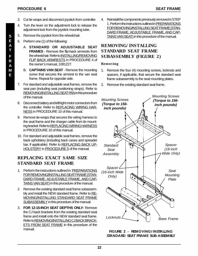
REMOVING/INSTALLINGSTANDARD SEAT FRAMESUBASSEMBLY (FIGURE 2)
Removing
1. Remove the four (4) mounting screws, locknuts andspacers, if applicable, that secure the standard seatframe subassembly to the seat mounting plates.
2. Remove the existing standard seat frame.
FIGURE 2 - REMOVING/INSTALLINGSTANDARD SEAT FRAME SUB-ASSEMBLY
Mounting Screws(Torque to 156-inch pounds)
StandardSeat
Assembly
Locknuts Base Frame
Spacer(16-inch
Wide Only)
SeatMounting
Plate
Spacer(16-inch Wide
Only)
Mounting Screws(Torque to 156-inch pounds)
SEAT
FRAME
PROCEDURE 6 SEAT FRAME
23
Installing
1. Position NEW standard seat frame subassembly onseat mount plates.
2. Secure NEW standard seat frame subassembly ontoseat mounting plates with the existing four (4) mount-ing screws, locknuts and spacers, if applicable. Torqueto 156-inch pounds.
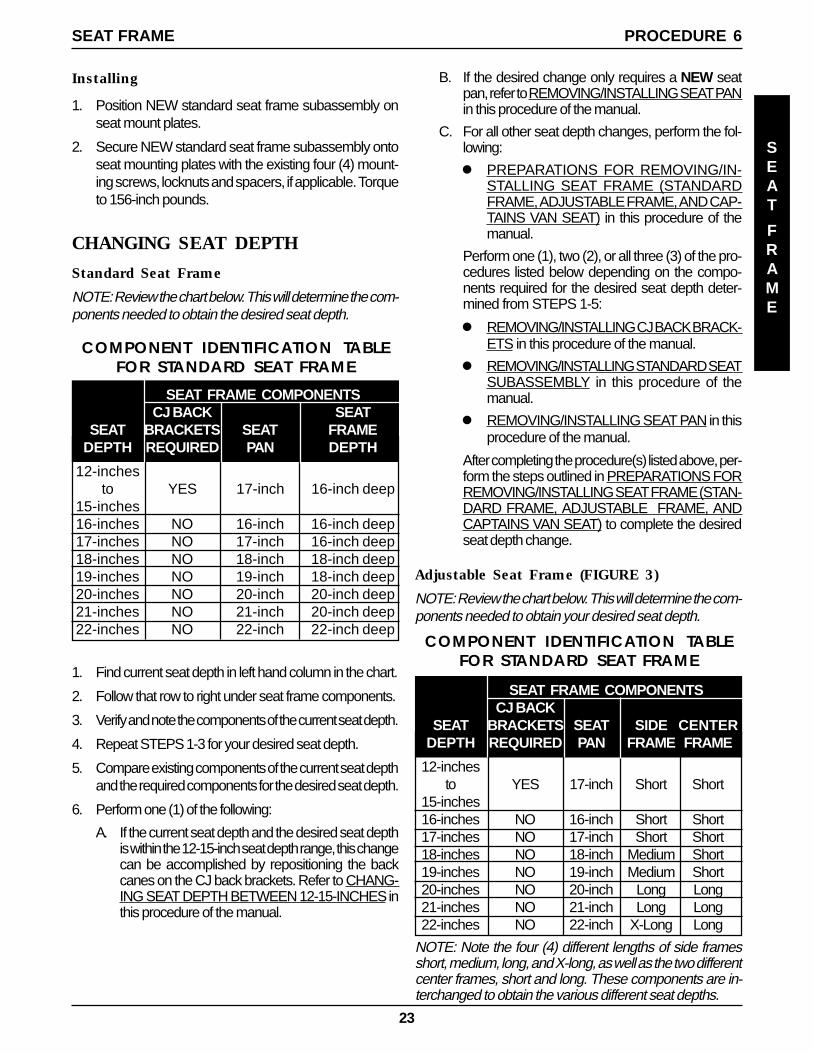
CHANGING SEAT DEPTH
Standard Seat Frame
NOTE: Review the chart below. This will determine the com-ponents needed to obtain the desired seat depth.
B. If the desired change only requires a NEW seatpan, refer to REMOVING/INSTALLING SEAT PANin this procedure of the manual.
C. For all other seat depth changes, perform the fol-lowing:
l PREPARATIONS FOR REMOVING/IN-STALLING SEAT FRAME (STANDARDFRAME, ADJUSTABLE FRAME, AND CAP-TAINS VAN SEAT) in this procedure of themanual.
Perform one (1), two (2), or all three (3) of the pro-cedures listed below depending on the compo-nents required for the desired seat depth deter-mined from STEPS 1-5:
l REMOVING/INSTALLING CJ BACK BRACK-ETS in this procedure of the manual.
l REMOVING/INSTALLING STANDARD SEATSUBASSEMBLY in this procedure of themanual.
l REMOVING/INSTALLING SEAT PAN in thisprocedure of the manual.
After completing the procedure(s) listed above, per-form the steps outlined in PREPARATIONS FORREMOVING/INSTALLING SEAT FRAME (STAN-DARD FRAME, ADJUSTABLE FRAME, ANDCAPTAINS VAN SEAT) to complete the desiredseat depth change.
Adjustable Seat Frame (FIGURE 3)
NOTE: Review the chart below. This will determine the com-ponents needed to obtain your desired seat depth.
SEAT FRAME COMPONENTSCJ BACK SEAT
SEAT BRACKETS SEAT FRAMEDEPTH REQUIRED PAN DEPTH
12-inchesto YES 17-inch 16-inch deep
15-inches16-inches NO 16-inch 16-inch deep17-inches NO 17-inch 16-inch deep18-inches NO 18-inch 18-inch deep19-inches NO 19-inch 18-inch deep20-inches NO 20-inch 20-inch deep21-inches NO 21-inch 20-inch deep22-inches NO 22-inch 22-inch deep
COMPONENT IDENTIFICATION TABLEFOR STANDARD SEAT FRAME
1. Find current seat depth in left hand column in the chart.
2. Follow that row to right under seat frame components.
3. Verify and note the components of the current seat depth.
4. Repeat STEPS 1-3 for your desired seat depth.
5. Compare existing components of the current seat depthand the required components for the desired seat depth.
6. Perform one (1) of the following:
A. If the current seat depth and the desired seat depthis within the 12-15-inch seat depth range, this changecan be accomplished by repositioning the backcanes on the CJ back brackets. Refer to CHANG-ING SEAT DEPTH BETWEEN 12-15-INCHES inthis procedure of the manual.
NOTE: Note the four (4) different lengths of side framesshort, medium, long, and X-long, as well as the two differentcenter frames, short and long. These components are in-terchanged to obtain the various different seat depths.
SEAT FRAME COMPONENTSCJ BACK
SEAT BRACKETS SEAT SIDE CENTERDEPTH REQUIRED PAN FRAME FRAME
12-inchesto YES 17-inch Short Short
15-inches16-inches NO 16-inch Short Short17-inches NO 17-inch Short Short18-inches NO 18-inch Medium Short19-inches NO 19-inch Medium Short20-inches NO 20-inch Long Long21-inches NO 21-inch Long Long22-inches NO 22-inch X-Long Long
COMPONENT IDENTIFICATION TABLEFOR STANDARD SEAT FRAME
PROCEDURE 6SEAT FRAME
SEAT
FRAME
24
1. Find current seat depth in left hand column in the chart.
2. Follow that row to right under seat frame components.
3. Verify and note the components of the current seat depth.
4. Repeat STEPS 1-3 for the desired seat depth.
5. Compare existing components of the current seat depthand the required components for the desired seat depth.
To adjust the depth of the seat on the wheelchair, usethe following guidelines:
If the current seat depth is and the desired seat depth arewithin the 12-15-inch seat depth range, this change can beaccomplished by repositioning the back canes on the CJback brackets. Refer to CHANGING SEAT DEPTH BE-TWEEN 12-15-INCHES in this procedure of the manual.
If the desired change only requires a NEW seat pan, refer toREMOVING/INSTALLING SEAT PAN in this procedure ofthe manual.
If the desired change requires the removal/installation of CJback brackets, refer to REMOVING/INSTALLING CJ BACKBRACKETS in PROCEDURE 8 of this manual.
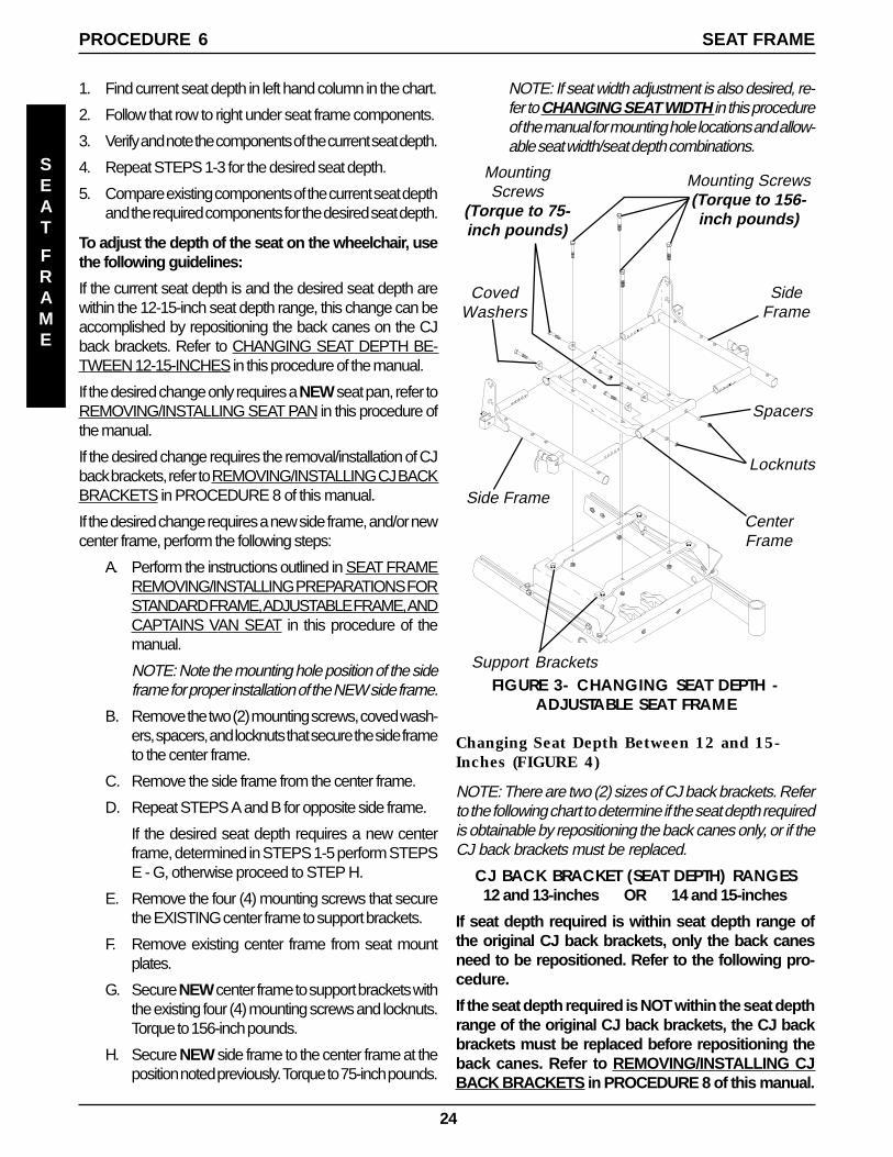
If the desired change requires a new side frame, and/or newcenter frame, perform the following steps:
A. Perform the instructions outlined in SEAT FRAMEREMOVING/INSTALLING PREPARATIONS FORSTANDARD FRAME, ADJUSTABLE FRAME, ANDCAPTAINS VAN SEAT in this procedure of themanual.
NOTE: Note the mounting hole position of the sideframe for proper installation of the NEW side frame.
B. Remove the two (2) mounting screws, coved wash-ers, spacers, and locknuts that secure the side frameto the center frame.
C. Remove the side frame from the center frame.
D. Repeat STEPS A and B for opposite side frame.
If the desired seat depth requires a new centerframe, determined in STEPS 1-5 perform STEPSE - G, otherwise proceed to STEP H.
E. Remove the four (4) mounting screws that securethe EXISTING center frame to support brackets.
F. Remove existing center frame from seat mountplates.
G. Secure NEW center frame to support brackets withthe existing four (4) mounting screws and locknuts.Torque to 156-inch pounds.
H. Secure NEW side frame to the center frame at theposition noted previously. Torque to 75-inch pounds.
NOTE: If seat width adjustment is also desired, re-fer to CHANGING SEAT WIDTH in this procedureof the manual for mounting hole locations and allow-able seat width/seat depth combinations.
FIGURE 3- CHANGING SEAT DEPTH -ADJUSTABLE SEAT FRAME
Side Frame
SideFrame
CenterFrame
MountingScrews
(Torque to 75-inch pounds)
CovedWashers
Spacers
Locknuts
Mounting Screws(Torque to 156-inch pounds)
Support Brackets
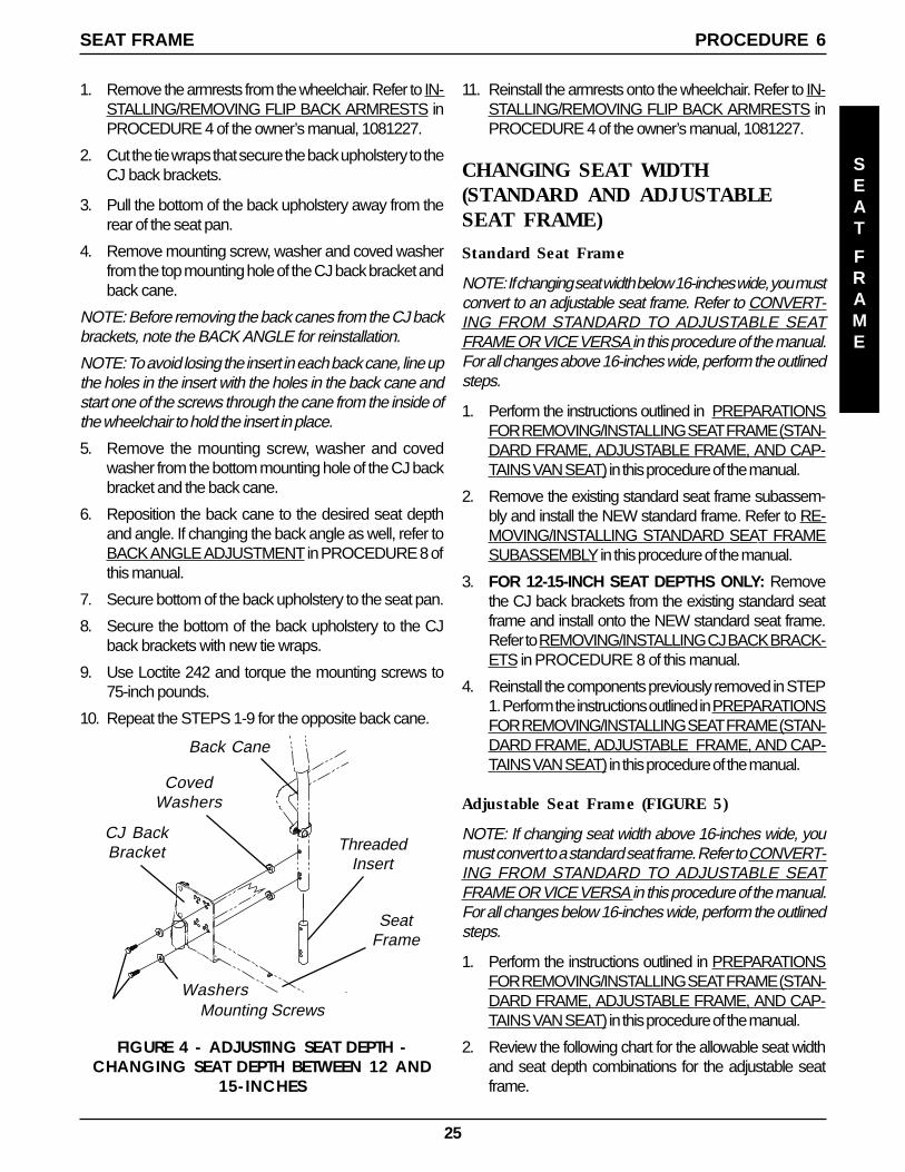
Changing Seat Depth Between 12 and 15-Inches (FIGURE 4)
NOTE: There are two (2) sizes of CJ back brackets. Referto the following chart to determine if the seat depth requiredis obtainable by repositioning the back canes only, or if theCJ back brackets must be replaced.
CJ BACK BRACKET (SEAT DEPTH) RANGES12 and 13-inches OR 14 and 15-inches
If seat depth required is within seat depth range ofthe original CJ back brackets, only the back canesneed to be repositioned. Refer to the following pro-cedure.
If the seat depth required is NOT within the seat depthrange of the original CJ back brackets, the CJ backbrackets must be replaced before repositioning theback canes. Refer to REMOVING/INSTALLING CJBACK BRACKETS in PROCEDURE 8 of this manual.
SEAT
FRAME
PROCEDURE 6 SEAT FRAME
25
FIGURE 4 - ADJUSTING SEAT DEPTH -CHANGING SEAT DEPTH BETWEEN 12 AND
15-INCHES
CJ BackBracket
SeatFrame
ThreadedInsert
Washers
Back Cane
CovedWashers
Mounting Screws
1. Remove the armrests from the wheelchair. Refer to IN-STALLING/REMOVING FLIP BACK ARMRESTS inPROCEDURE 4 of the owner’s manual, 1081227.
2. Cut the tie wraps that secure the back upholstery to theCJ back brackets.
3. Pull the bottom of the back upholstery away from therear of the seat pan.
4. Remove mounting screw, washer and coved washerfrom the top mounting hole of the CJ back bracket andback cane.
NOTE: Before removing the back canes from the CJ backbrackets, note the BACK ANGLE for reinstallation.
NOTE: To avoid losing the insert in each back cane, line upthe holes in the insert with the holes in the back cane andstart one of the screws through the cane from the inside ofthe wheelchair to hold the insert in place.
5. Remove the mounting screw, washer and covedwasher from the bottom mounting hole of the CJ backbracket and the back cane.
6. Reposition the back cane to the desired seat depthand angle. If changing the back angle as well, refer toBACK ANGLE ADJUSTMENT in PROCEDURE 8 ofthis manual.
7. Secure bottom of the back upholstery to the seat pan.
8. Secure the bottom of the back upholstery to the CJback brackets with new tie wraps.
9. Use Loctite 242 and torque the mounting screws to75-inch pounds.
10. Repeat the STEPS 1-9 for the opposite back cane.
11. Reinstall the armrests onto the wheelchair. Refer to IN-STALLING/REMOVING FLIP BACK ARMRESTS inPROCEDURE 4 of the owner’s manual, 1081227.
CHANGING SEAT WIDTH(STANDARD AND ADJUSTABLESEAT FRAME)
Standard Seat Frame
NOTE: If changing seat width below 16-inches wide, you mustconvert to an adjustable seat frame. Refer to CONVERT-ING FROM STANDARD TO ADJUSTABLE SEATFRAME OR VICE VERSA in this procedure of the manual.For all changes above 16-inches wide, perform the outlinedsteps.
1. Perform the instructions outlined in PREPARATIONSFOR REMOVING/INSTALLING SEAT FRAME (STAN-DARD FRAME, ADJUSTABLE FRAME, AND CAP-TAINS VAN SEAT) in this procedure of the manual.
2. Remove the existing standard seat frame subassem-bly and install the NEW standard frame. Refer to RE-MOVING/INSTALLING STANDARD SEAT FRAMESUBASSEMBLY in this procedure of the manual.
3. FOR 12-15-INCH SEAT DEPTHS ONLY: Removethe CJ back brackets from the existing standard seatframe and install onto the NEW standard seat frame.Refer to REMOVING/INSTALLING CJ BACK BRACK-ETS in PROCEDURE 8 of this manual.
4. Reinstall the components previously removed in STEP1. Perform the instructions outlined in PREPARATIONSFOR REMOVING/INSTALLING SEAT FRAME (STAN-DARD FRAME, ADJUSTABLE FRAME, AND CAP-TAINS VAN SEAT) in this procedure of the manual.
Adjustable Seat Frame (FIGURE 5)
NOTE: If changing seat width above 16-inches wide, youmust convert to a standard seat frame. Refer to CONVERT-ING FROM STANDARD TO ADJUSTABLE SEATFRAME OR VICE VERSA in this procedure of the manual.For all changes below 16-inches wide, perform the outlinedsteps.
1. Perform the instructions outlined in PREPARATIONSFOR REMOVING/INSTALLING SEAT FRAME (STAN-DARD FRAME, ADJUSTABLE FRAME, AND CAP-TAINS VAN SEAT) in this procedure of the manual.
2. Review the following chart for the allowable seat widthand seat depth combinations for the adjustable seatframe.
PROCEDURE 6SEAT FRAME
SEAT
FRAME
26
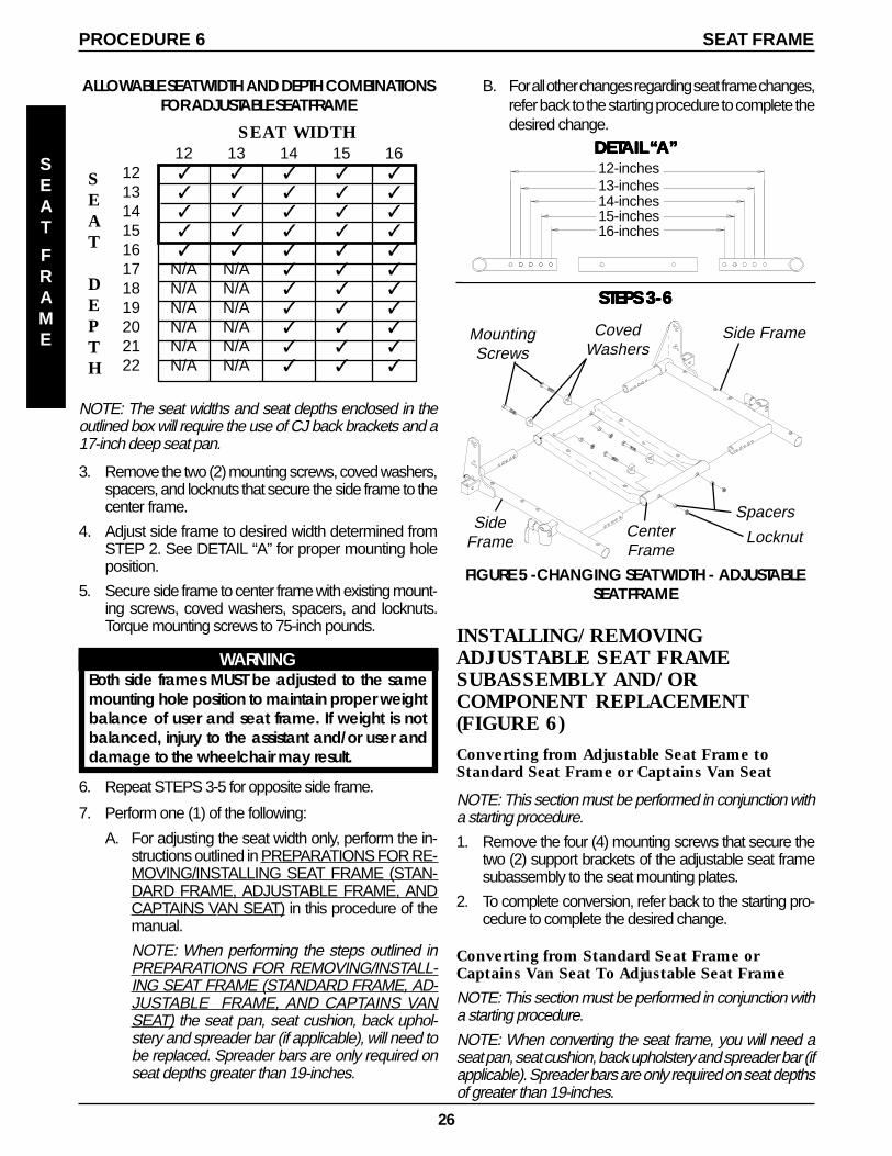
ALLOWABLE SEAT WIDTH AND DEPTH COMBINATIONSFOR ADJUSTABLE SEAT FRAME
NOTE: The seat widths and seat depths enclosed in theoutlined box will require the use of CJ back brackets and a17-inch deep seat pan.
3. Remove the two (2) mounting screws, coved washers,spacers, and locknuts that secure the side frame to thecenter frame.
4. Adjust side frame to desired width determined fromSTEP 2. See DETAIL “A” for proper mounting holeposition.
5. Secure side frame to center frame with existing mount-ing screws, coved washers, spacers, and locknuts.Torque mounting screws to 75-inch pounds.
WARNINGBoth side frames MUST be adjusted to the samemounting hole position to maintain proper weightbalance of user and seat frame. If weight is notbalanced, injury to the assistant and/or user anddamage to the wheelchair may result.
6. Repeat STEPS 3-5 for opposite side frame.
7. Perform one (1) of the following:
A. For adjusting the seat width only, perform the in-structions outlined in PREPARATIONS FOR RE-MOVING/INSTALLING SEAT FRAME (STAN-DARD FRAME, ADJUSTABLE FRAME, ANDCAPTAINS VAN SEAT) in this procedure of themanual.
NOTE: When performing the steps outlined inPREPARATIONS FOR REMOVING/INSTALL-ING SEAT FRAME (STANDARD FRAME, AD-JUSTABLE FRAME, AND CAPTAINS VANSEAT) the seat pan, seat cushion, back uphol-stery and spreader bar (if applicable), will need tobe replaced. Spreader bars are only required onseat depths greater than 19-inches.
FIGURE 5 -CHANGING SEAT WIDTH - ADJUSTABLESEAT FRAME
SideFrame
STEPS 3-6STEPS 3-6STEPS 3-6STEPS 3-6STEPS 3-6
Side Frame
CenterFrame
MountingScrews
CovedWashers
Spacers
Locknut
INSTALLING/REMOVINGADJUSTABLE SEAT FRAMESUBASSEMBLY AND/ORCOMPONENT REPLACEMENT(FIGURE 6)Converting from Adjustable Seat Frame toStandard Seat Frame or Captains Van Seat
NOTE: This section must be performed in conjunction witha starting procedure.
1. Remove the four (4) mounting screws that secure thetwo (2) support brackets of the adjustable seat framesubassembly to the seat mounting plates.
2. To complete conversion, refer back to the starting pro-cedure to complete the desired change.
Converting from Standard Seat Frame orCaptains Van Seat To Adjustable Seat Frame
NOTE: This section must be performed in conjunction witha starting procedure.
NOTE: When converting the seat frame, you will need aseat pan, seat cushion, back upholstery and spreader bar (ifapplicable). Spreader bars are only required on seat depthsof greater than 19-inches.
SEAT
FRAME
PROCEDURE 6 SEAT FRAME
12 13 14 15 1612 13 14 15 16 17 N/A N/A 18 N/A N/A 19 N/A N/A 20 N/A N/A 21 N/A N/A 22 N/A N/A
SEAT
DEPTH
SEAT WIDTH
B. For all other changes regarding seat frame changes,refer back to the starting procedure to complete thedesired change.
DETDETDETDETDETAIL AIL AIL AIL AIL “““““A”A”A”A”A”12-inches13-inches14-inches15-inches16-inches
SEAT
FRAME
27
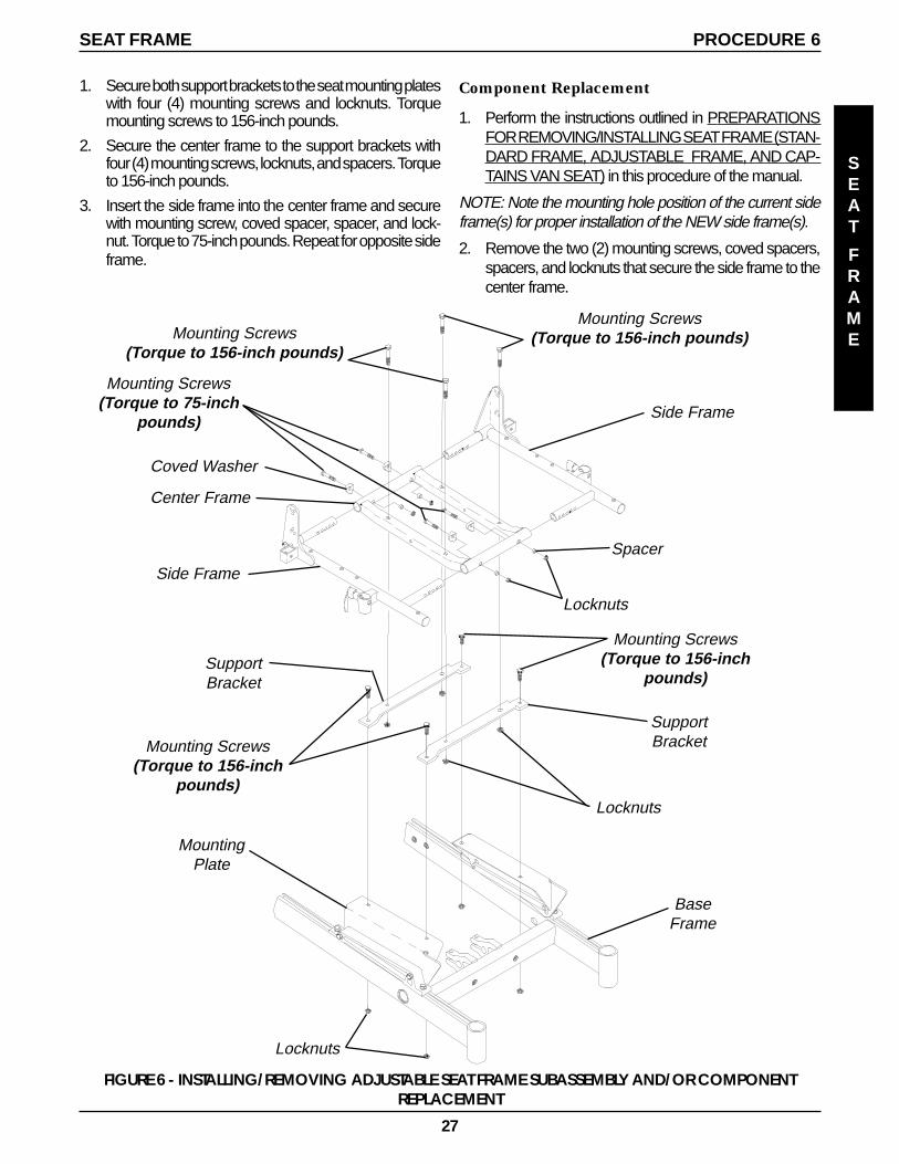
Mounting Screws(Torque to 156-inch pounds)
Side Frame
Side Frame
Center Frame
Spacer
Locknuts
SupportBracket
BaseFrame
Coved Washer
Locknuts
Locknuts
SupportBracketMounting Screws
(Torque to 156-inchpounds)
Mounting Screws(Torque to 156-inch
pounds)
MountingPlate
Mounting Screws(Torque to 75-inch
pounds)
1. Secure both support brackets to the seat mounting plateswith four (4) mounting screws and locknuts. Torquemounting screws to 156-inch pounds.
2. Secure the center frame to the support brackets withfour (4) mounting screws, locknuts, and spacers. Torqueto 156-inch pounds.
3. Insert the side frame into the center frame and securewith mounting screw, coved spacer, spacer, and lock-nut. Torque to 75-inch pounds. Repeat for opposite sideframe.
Component Replacement
1. Perform the instructions outlined in PREPARATIONSFOR REMOVING/INSTALLING SEAT FRAME (STAN-DARD FRAME, ADJUSTABLE FRAME, AND CAP-TAINS VAN SEAT) in this procedure of the manual.
NOTE: Note the mounting hole position of the current sideframe(s) for proper installation of the NEW side frame(s).
2. Remove the two (2) mounting screws, coved spacers,spacers, and locknuts that secure the side frame to thecenter frame.
Mounting Screws(Torque to 156-inch pounds)
PROCEDURE 6SEAT FRAME
SEAT
FRAME
FIGURE 6 - INSTALLING/REMOVING ADJUSTABLE SEAT FRAME SUBASSEMBLY AND/OR COMPONENTREPLACEMENT
28
3. Perform one (1) of the following:
A. If center frame needs replaced, repeat STEP 2 foropposite side frame and proceed to STEP 4.
B. If opposite side frame needs replaced, repeat STEP2, then proceed to STEP 6. Otherwise proceed toSTEP 6.
4. Remove the four (4) mounting screws and locknuts thatsecure the center frame to the support brackets.
5. Secure NEW center frame to support brackets with ex-isting four (4) mounting screws and locknuts. Torque to156-inch pounds.
WARNINGBoth side frames MUST be adjusted to the samemounting hole position to maintain proper weightbalance of user and seat frame. If weight is notbalanced, injury to the assistant and/or user anddamage to the wheelchair may result.
6. Install new/existing side frame(s) into new/existing cen-ter frame at the mounting position previously noted.Torque to 75-inch pounds.
7. Perform the instructions outlined in PREPARATIONSFOR REMOVING/INSTALLING SEAT FRAME (STAN-DARD FRAME, ADJUSTABLE FRAME, AND CAP-TAINS VAN SEAT) in this procedure of the manual.
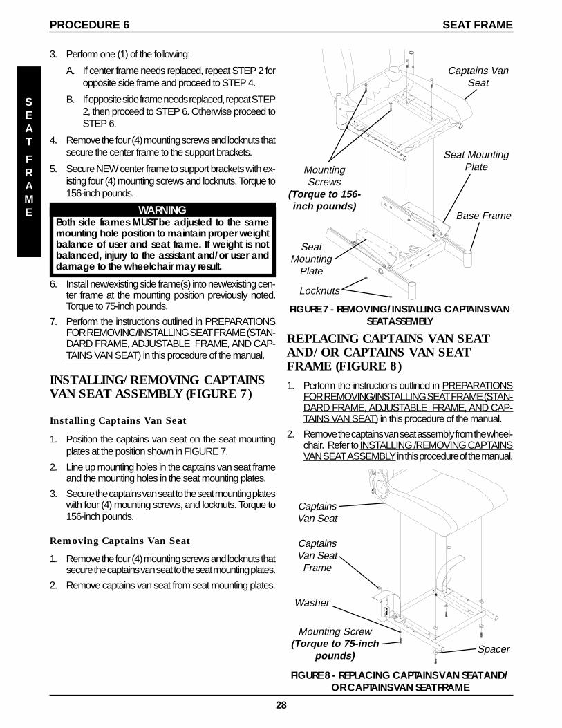
INSTALLING/REMOVING CAPTAINSVAN SEAT ASSEMBLY (FIGURE 7)
Installing Captains Van Seat
1. Position the captains van seat on the seat mountingplates at the position shown in FIGURE 7.
2. Line up mounting holes in the captains van seat frameand the mounting holes in the seat mounting plates.
3. Secure the captains van seat to the seat mounting plateswith four (4) mounting screws, and locknuts. Torque to156-inch pounds.
Removing Captains Van Seat
1. Remove the four (4) mounting screws and locknuts thatsecure the captains van seat to the seat mounting plates.
2. Remove captains van seat from seat mounting plates.
FIGURE 7 - REMOVING/INSTALLING CAPTAINS VANSEAT ASSEMBLY
MountingScrews
(Torque to 156-inch pounds)
Locknuts
SeatMounting
Plate
Base Frame
Seat MountingPlate
Captains VanSeat
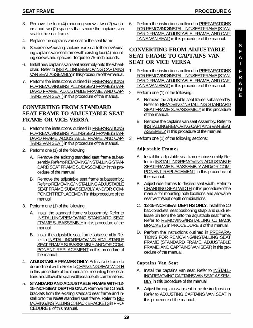
REPLACING CAPTAINS VAN SEATAND/OR CAPTAINS VAN SEATFRAME (FIGURE 8)1. Perform the instructions outlined in PREPARATIONS
FOR REMOVING/INSTALLING SEAT FRAME (STAN-DARD FRAME, ADJUSTABLE FRAME, AND CAP-TAINS VAN SEAT) in this procedure of the manual.
2. Remove the captains van seat assembly from the wheel-chair. Refer to INSTALLING /REMOVING CAPTAINSVAN SEAT ASSEMBLY in this procedure of the manual.
Mounting Screw(Torque to 75-inch
pounds)
FIGURE 8 - REPLACING CAPTAINS VAN SEAT AND/OR CAPTAINS VAN SEAT FRAME
CaptainsVan Seat
Frame
CaptainsVan Seat
Washer
Spacer
SEAT
FRAME
PROCEDURE 6 SEAT FRAME
29
6. Perform the instructions outlined in PREPARATIONSFOR REMOVING/INSTALLING SEAT FRAME (STAN-DARD FRAME, ADJUSTABLE FRAME, AND CAP-TAINS VAN SEAT) in this procedure of the manual.
CONVERTING FROM ADJUSTABLESEAT FRAME TO CAPTAINS VANSEAT OR VICE VERSA1. Perform the instructions outlined in PREPARATIONS
FOR REMOVING/INSTALLING SEAT FRAME (STAN-DARD FRAME, ADJUSTABLE FRAME, AND CAP-TAINS VAN SEAT) in this procedure of the manual.
2. Perform one (1) of the following:
A. Remove the adjustable seat frame subassembly.Refer to REMOVING/INSTALLING STANDARDSEAT FRAME SUBASSEMBLY in this procedureof the manual.
B. Remove the captains van seat Assembly. Refer toINSTALLING/REMOVING CAPTAINS VAN SEATASSEMBLY in this procedure of the manual.
3. Perform one (1) of the following sections:
Adjustable Frames
A. Install the adjustable seat frame subassembly. Re-fer to INSTALLING/REMOVING ADJUSTABLESEAT FRAME SUBASSEMBLY AND/OR COM-PONENT REPLACEMENT in this procedure ofthe manual.
B. Adjust side frames to desired seat width. Refer toCHANGING SEAT WIDTH in this procedure of themanual for mounting hole locations and allowableseat width/seat depth combinations.
C. 12-15-INCH SEAT DEPTHS ONLY: Install the CJback brackets, seat positioning strap, and quick re-lease pin from the onto the adjustable seat frame.Refer to REMOVING/INSTALLING CJ BACKBRACKETS in PROCEDURE 8 of this manual.
D. Perform the instructions outlined in PREPARA-TIONS FOR REMOVING/INSTALLING SEATFRAME (STANDARD FRAME, ADJUSTABLEFRAME, AND CAPTAINS VAN SEAT) in this pro-cedure of the manual.
Captains Van Seat
A. Install the captains van seat. Refer to INSTALL-ING/REMOVING CAPTAINS VAN SEAT ASSEM-BLY in this procedure of the manual.
B. Adjust the captains van seat to the desired position.Refer to ADJUSTING CAPTAINS VAN SEAT inthis procedure of the manual.
3. Remove the four (4) mounting screws, two (2) wash-ers, and two (2) spacers that secure the captains vanseat to the seat frame.
4. Replace the captains van seat or the seat frame.
5. Secure new/existing captains van seat to the new/exist-ing captains van seat frame with existing four (4) mount-ing screws and spacers. Torque to 75- inch pounds.
6. Install new captains van seat assembly onto the wheel-chair. Refer to INSTALLING/REMOVING CAPTAINSVAN SEAT ASSEMBLY in this procedure of the manual.
7. Perform the instructions outlined in PREPARATIONSFOR REMOVING/INSTALLING SEAT FRAME (STAN-DARD FRAME, ADJUSTABLE FRAME, AND CAP-TAINS VAN SEAT) in this procedure of the manual.
CONVERTING FROM STANDARDSEAT FRAME TO ADJUSTABLE SEATFRAME OR VICE VERSA1. Perform the instructions outlined in PREPARATIONS
FOR REMOVING/INSTALLING SEAT FRAME (STAN-DARD FRAME, ADJUSTABLE FRAME, AND CAP-TAINS VAN SEAT) in this procedure of the manual.
2. Perform one (1) of the following:
A. Remove the existing standard seat frame subas-sembly. Refer to REMOVING/INSTALLING STAN-DARD SEAT FRAME SUBASSEMBLY in this pro-cedure of the manual.
B. Remove the adjustable seat frame subassembly.Refer to REMOVING/INSTALLING ADJUSTABLESEAT FRAME SUBASSEMBLY AND/OR COM-PONENT REPLACEMENT in this procedure of themanual.
3. Perform one (1) of the following:
A. Install the standard frame subassembly. Refer toINSTALLING/REMOVING STANDARD SEATFRAME SUBASSEMBLY in this procedure of themanual.
B. Install the adjustable seat frame subassembly. Re-fer to INSTALLING/REMOVING ADJUSTABLESEAT FRAME SUBASSEMBLY AND/OR COM-PONENT REPLACEMENT in this procedure ofthe manual.
4. ADJUSTABLE FRAMES ONLY: Adjust side frame todesired seat width. Refer to CHANGING SEAT WIDTHin this procedure of the manual for mounting hole loca-tions and allowable seat width/seat depth combinations.
5. STANDARD AND ADJUSTABLE FRAME WITH 12-15-INCH SEAT DEPTHS ONLY: Remove the CJ backbrackets from the existing standard seat frame and in-stall onto the NEW standard seat frame. Refer to RE-MOVING/INSTALLING CJ BACK BRACKETS in PRO-CEDURE 8 of this manual.
PROCEDURE 6SEAT FRAME
SEAT
FRAME
30
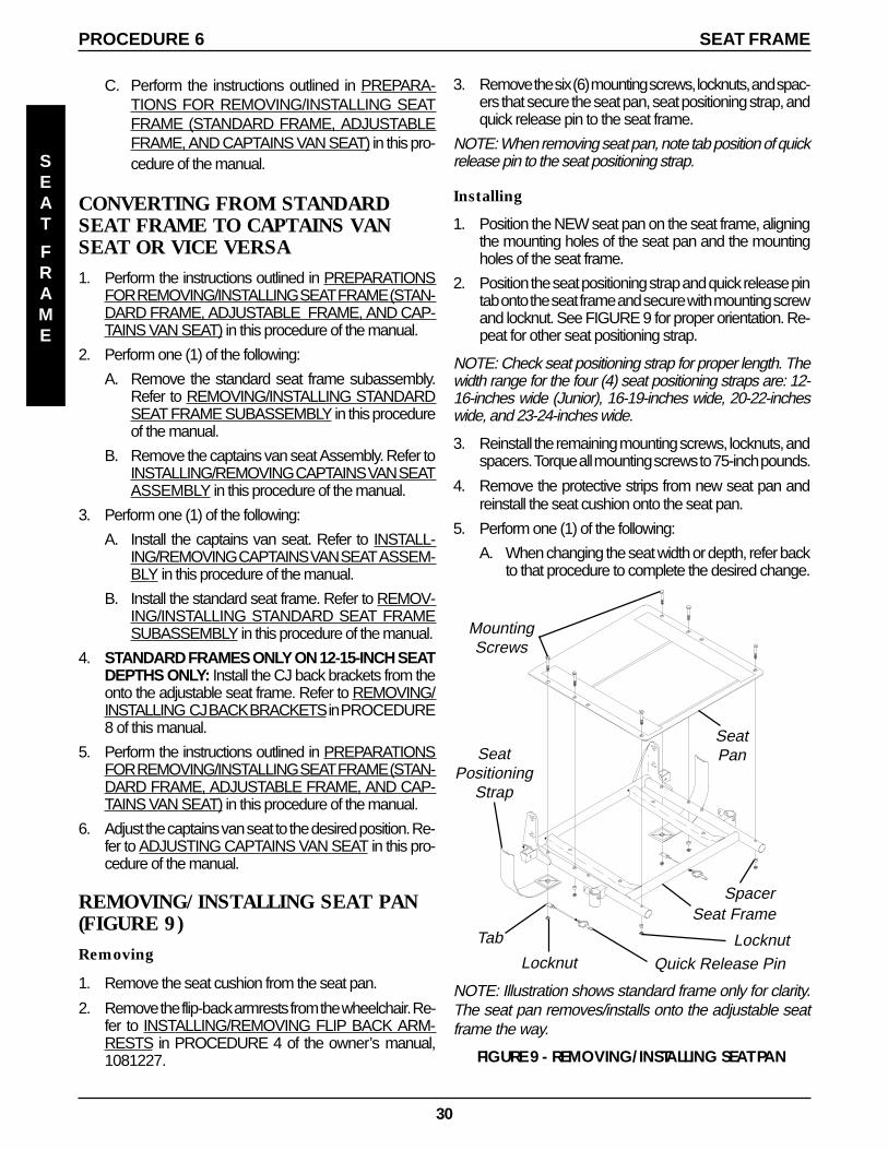
3. Remove the six (6) mounting screws, locknuts, and spac-ers that secure the seat pan, seat positioning strap, andquick release pin to the seat frame.
NOTE: When removing seat pan, note tab position of quickrelease pin to the seat positioning strap.
Installing
1. Position the NEW seat pan on the seat frame, aligningthe mounting holes of the seat pan and the mountingholes of the seat frame.
2. Position the seat positioning strap and quick release pintab onto the seat frame and secure with mounting screwand locknut. See FIGURE 9 for proper orientation. Re-peat for other seat positioning strap.
NOTE: Check seat positioning strap for proper length. Thewidth range for the four (4) seat positioning straps are: 12-16-inches wide (Junior), 16-19-inches wide, 20-22-incheswide, and 23-24-inches wide.
3. Reinstall the remaining mounting screws, locknuts, andspacers. Torque all mounting screws to 75-inch pounds.
4. Remove the protective strips from new seat pan andreinstall the seat cushion onto the seat pan.
5. Perform one (1) of the following:
A. When changing the seat width or depth, refer backto that procedure to complete the desired change.
FIGURE 9 - REMOVING/INSTALLING SEAT PAN
SeatPan
Seat Frame
SeatPositioning
Strap
Locknut Quick Release Pin
NOTE: Illustration shows standard frame only for clarity.The seat pan removes/installs onto the adjustable seatframe the way.
MountingScrews
Tab Locknut
Spacer
C. Perform the instructions outlined in PREPARA-TIONS FOR REMOVING/INSTALLING SEATFRAME (STANDARD FRAME, ADJUSTABLEFRAME, AND CAPTAINS VAN SEAT) in this pro-cedure of the manual.
CONVERTING FROM STANDARDSEAT FRAME TO CAPTAINS VANSEAT OR VICE VERSA1. Perform the instructions outlined in PREPARATIONS
FOR REMOVING/INSTALLING SEAT FRAME (STAN-DARD FRAME, ADJUSTABLE FRAME, AND CAP-TAINS VAN SEAT) in this procedure of the manual.
2. Perform one (1) of the following:
A. Remove the standard seat frame subassembly.Refer to REMOVING/INSTALLING STANDARDSEAT FRAME SUBASSEMBLY in this procedureof the manual.
B. Remove the captains van seat Assembly. Refer toINSTALLING/REMOVING CAPTAINS VAN SEATASSEMBLY in this procedure of the manual.
3. Perform one (1) of the following:
A. Install the captains van seat. Refer to INSTALL-ING/REMOVING CAPTAINS VAN SEAT ASSEM-BLY in this procedure of the manual.
B. Install the standard seat frame. Refer to REMOV-ING/INSTALLING STANDARD SEAT FRAMESUBASSEMBLY in this procedure of the manual.
4. STANDARD FRAMES ONLY ON 12-15-INCH SEATDEPTHS ONLY: Install the CJ back brackets from theonto the adjustable seat frame. Refer to REMOVING/INSTALLING CJ BACK BRACKETS in PROCEDURE8 of this manual.
5. Perform the instructions outlined in PREPARATIONSFOR REMOVING/INSTALLING SEAT FRAME (STAN-DARD FRAME, ADJUSTABLE FRAME, AND CAP-TAINS VAN SEAT) in this procedure of the manual.
6. Adjust the captains van seat to the desired position. Re-fer to ADJUSTING CAPTAINS VAN SEAT in this pro-cedure of the manual.
REMOVING/INSTALLING SEAT PAN(FIGURE 9)Removing
1. Remove the seat cushion from the seat pan.
2. Remove the flip-back armrests from the wheelchair. Re-fer to INSTALLING/REMOVING FLIP BACK ARM-RESTS in PROCEDURE 4 of the owner’s manual,1081227.
SEAT
FRAME
PROCEDURE 6 SEAT FRAME
31
B. Reinstall the flip-back armrests from the wheelchair.Refer to INSTALLING/REMOVING FLIP BACKARMRESTS in PROCEDURE 4 of the owner’smanual, 1081227.
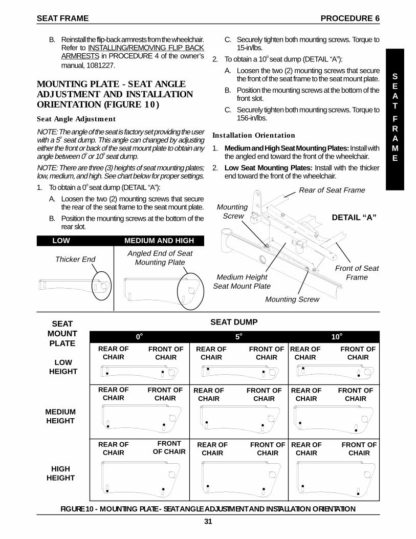
MOUNTING PLATE - SEAT ANGLEADJUSTMENT AND INSTALLATIONORIENTATION (FIGURE 10)Seat Angle Adjustment
NOTE: The angle of the seat is factory set providing the userwith a 5o seat dump. This angle can changed by adjustingeither the front or back of the seat mount plate to obtain anyangle between 0o or 10o seat dump.
NOTE: There are three (3) heights of seat mounting plates;low, medium, and high. See chart below for proper settings.
1. To obtain a 0o seat dump (DETAIL “A”):
A. Loosen the two (2) mounting screws that securethe rear of the seat frame to the seat mount plate.
B. Position the mounting screws at the bottom of therear slot.
C. Securely tighten both mounting screws. Torque to15-in/lbs.
2. To obtain a 10o seat dump (DETAIL “A”):
A. Loosen the two (2) mounting screws that securethe front of the seat frame to the seat mount plate.
B. Position the mounting screws at the bottom of thefront slot.
C. Securely tighten both mounting screws. Torque to156-in/lbs.
Installation Orientation
1. Medium and High Seat Mounting Plates: Install withthe angled end toward the front of the wheelchair.
2. Low Seat Mounting Plates: Install with the thickerend toward the front of the wheelchair.
Mounting Screw
Mounting Screw
Rear of Seat Frame
Medium HeightSeat Mount Plate
Angled End of SeatMounting Plate
LOW MEDIUM AND HIGH
Thicker End
DETAIL “A”
FIGURE 10 - MOUNTING PLATE - SEAT ANGLE ADJUSTMENT AND INSTALLATION ORIENTATION
MEDIUMHEIGHT
HIGHHEIGHT
LOWHEIGHT
0o 5o 10o
SEAT DUMPSEATMOUNTPLATE
FRONT OFCHAIR
REAR OFCHAIR
FRONT OFCHAIR
REAR OFCHAIR
FRONT OFCHAIR
REAR OFCHAIR
FRONT OFCHAIR
REAR OFCHAIR
FRONT OFCHAIR
REAR OFCHAIR
FRONT OFCHAIR
REAR OFCHAIR
FRONTOF CHAIR
REAR OFCHAIR
FRONT OFCHAIR
REAR OFCHAIR
FRONT OFCHAIR
REAR OFCHAIR
SEAT
FRAME
PROCEDURE 6SEAT FRAME
Front of SeatFrame
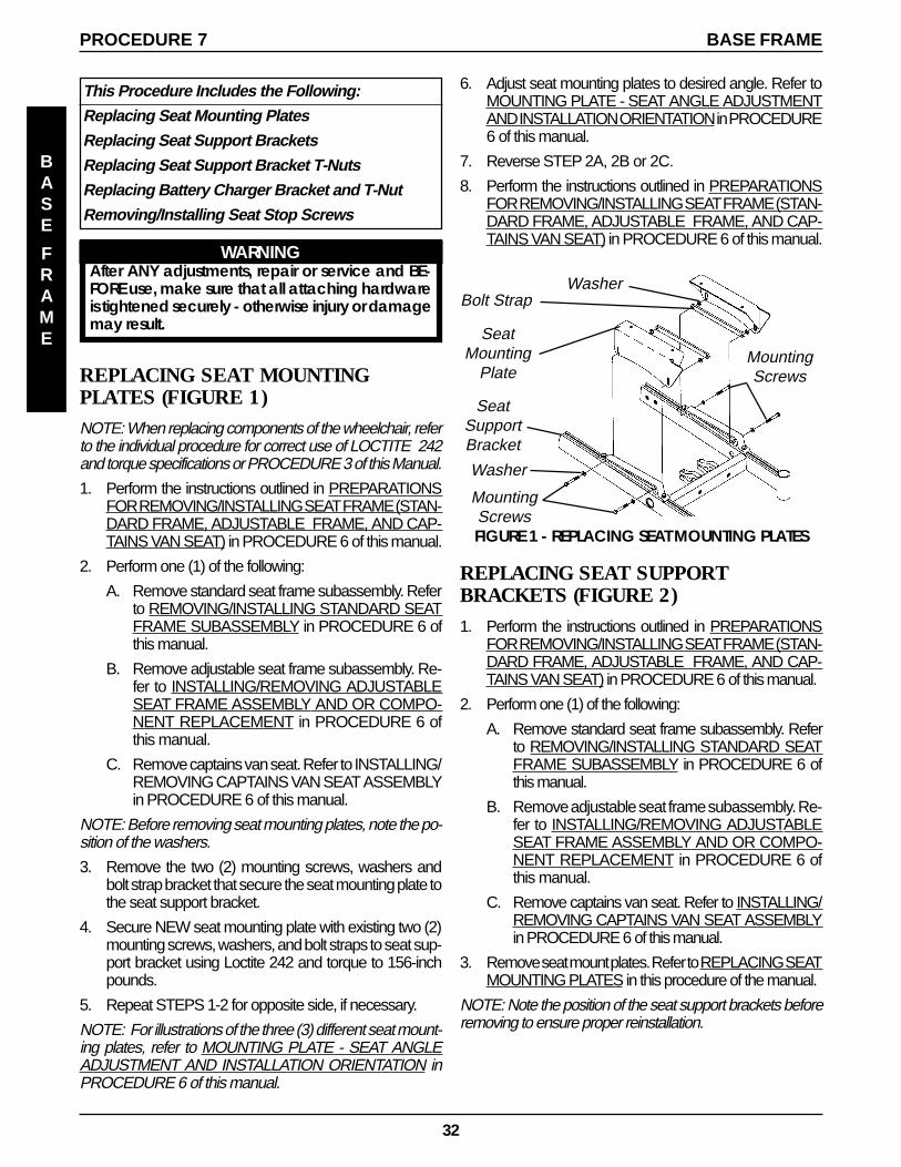
32
This Procedure Includes the Following:
Replacing Seat Mounting Plates
Replacing Seat Support Brackets
Replacing Seat Support Bracket T-Nuts
Replacing Battery Charger Bracket and T-Nut
Removing/Installing Seat Stop Screws
WARNINGAfter ANY adjustments, repair or service and BE-FORE use, make sure that all attaching hardwareis tightened securely - otherwise injury or damagemay result.
REPLACING SEAT MOUNTINGPLATES (FIGURE 1)NOTE: When replacing components of the wheelchair, referto the individual procedure for correct use of LOCTITE 242and torque specifications or PROCEDURE 3 of this Manual.
1. Perform the instructions outlined in PREPARATIONSFOR REMOVING/INSTALLING SEAT FRAME (STAN-DARD FRAME, ADJUSTABLE FRAME, AND CAP-TAINS VAN SEAT) in PROCEDURE 6 of this manual.
2. Perform one (1) of the following:
A. Remove standard seat frame subassembly. Referto REMOVING/INSTALLING STANDARD SEATFRAME SUBASSEMBLY in PROCEDURE 6 ofthis manual.
B. Remove adjustable seat frame subassembly. Re-fer to INSTALLING/REMOVING ADJUSTABLESEAT FRAME ASSEMBLY AND OR COMPO-NENT REPLACEMENT in PROCEDURE 6 ofthis manual.
C. Remove captains van seat. Refer to INSTALLING/REMOVING CAPTAINS VAN SEAT ASSEMBLYin PROCEDURE 6 of this manual.
NOTE: Before removing seat mounting plates, note the po-sition of the washers.
3. Remove the two (2) mounting screws, washers andbolt strap bracket that secure the seat mounting plate tothe seat support bracket.
4. Secure NEW seat mounting plate with existing two (2)mounting screws, washers, and bolt straps to seat sup-port bracket using Loctite 242 and torque to 156-inchpounds.
5. Repeat STEPS 1-2 for opposite side, if necessary.
NOTE: For illustrations of the three (3) different seat mount-ing plates, refer to MOUNTING PLATE - SEAT ANGLEADJUSTMENT AND INSTALLATION ORIENTATION inPROCEDURE 6 of this manual.
Washer
Washer
MountingScrews
SeatMounting
Plate
Bolt Strap
FIGURE 1 - REPLACING SEAT MOUNTING PLATES
6. Adjust seat mounting plates to desired angle. Refer toMOUNTING PLATE - SEAT ANGLE ADJUSTMENTAND INSTALLATION ORIENTATION in PROCEDURE6 of this manual.
7. Reverse STEP 2A, 2B or 2C.
8. Perform the instructions outlined in PREPARATIONSFOR REMOVING/INSTALLING SEAT FRAME (STAN-DARD FRAME, ADJUSTABLE FRAME, AND CAP-TAINS VAN SEAT) in PROCEDURE 6 of this manual.
SeatSupportBracket
MountingScrews
REPLACING SEAT SUPPORTBRACKETS (FIGURE 2)1. Perform the instructions outlined in PREPARATIONS
FOR REMOVING/INSTALLING SEAT FRAME (STAN-DARD FRAME, ADJUSTABLE FRAME, AND CAP-TAINS VAN SEAT) in PROCEDURE 6 of this manual.
2. Perform one (1) of the following:
A. Remove standard seat frame subassembly. Referto REMOVING/INSTALLING STANDARD SEATFRAME SUBASSEMBLY in PROCEDURE 6 ofthis manual.
B. Remove adjustable seat frame subassembly. Re-fer to INSTALLING/REMOVING ADJUSTABLESEAT FRAME ASSEMBLY AND OR COMPO-NENT REPLACEMENT in PROCEDURE 6 ofthis manual.
C. Remove captains van seat. Refer to INSTALLING/REMOVING CAPTAINS VAN SEAT ASSEMBLYin PROCEDURE 6 of this manual.
3. Remove seat mount plates. Refer to REPLACING SEATMOUNTING PLATES in this procedure of the manual.
NOTE: Note the position of the seat support brackets beforeremoving to ensure proper reinstallation.
BASE FRAMEPROCEDURE 7
BASE
FRAME
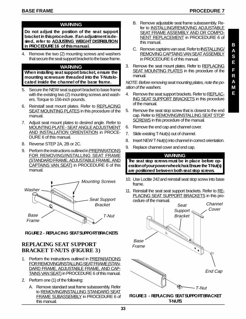
33
BASE FRAME PROCEDURE 7
BASE
FRAME
B. Remove adjustable seat frame subassembly. Re-fer to INSTALLING/REMOVING ADJUSTABLESEAT FRAME ASSEMBLY AND OR COMPO-NENT REPLACEMENT in PROCEDURE 6 ofthis manual.
C. Remove captains van seat. Refer to INSTALLING/REMOVING CAPTAINS VAN SEAT ASSEMBLYin PROCEDURE 6 of this manual.
3. Remove the seat mount plates. Refer to REPLACINGSEAT MOUNTING PLATES in this procedure of themanual.
NOTE: Before removing seat mounting plates, note the po-sition of the washers.
4. Remove the seat support brackets. Refer to REPLAC-ING SEAT SUPPORT BRACKETS in this procedureof the manual.
5. Remove the seat stop screw that is closest to the endcap. Refer to REMOVING/INSTALLING SEAT STOPSCREWS in this procedure of the manual.
6. Remove the end cap and channel cover.
7. Slide existing T-Nut(s) out of channel.
8. Insert NEW T-Nut(s) into channel in correct orientation.
9. Replace channel cover and end cap.
WARNINGThe seat stop screws must be in place before op-eration of your power wheelchair. Ensure the T-Nut(s)are positioned between both seat stop screws.
10. Use Loctite 242 and reinstall seat stop screw into baseframe.
11. Reinstall the seat seat support brackets. Refer to RE-PLACING SEAT SUPPORT BRACKETS in this pro-cedure of the manual.
FIGURE 2 - REPLACING SEAT SUPPORT BRACKETS
Washer
Seat SupportBracket
BaseFrame
Mounting Screws
T-Nut
WARNINGDo not adjust the position of the seat supportbracket in this procedure. If an adjustment is de-sired, refer to ADJUSTING WEIGHT DISTRIBUTIONin PROCEDURE 16 of this manual.
4. Remove the two (2) mounting screws and washersthat secure the seat support bracket to the base frame.
WARNINGWhen installing seat support bracket, ensure themounting screws are threaded into the T-Nuts lo-cated inside the channel of the base frame.
5. Secure the NEW seat support bracket to base framewith the existing two (2) mounting screws and wash-ers. Torque to 156-inch pounds.
6. Reinstall seat mount plates. Refer to REPLACINGSEAT MOUNTING PLATES in this procedure of themanual.
7. Adjust seat mount plates to desired angle. Refer toMOUNTING PLATE - SEAT ANGLE ADJUSTMENTAND INSTALLATION ORIENTATION in PROCE-DURE 6 of this manual.
8. Reverse STEP 2A, 2B or 2C.
9. Perform the instructions outlined in PREPARATIONSFOR REMOVING/INSTALLING SEAT FRAME(STANDARD FRAME, ADJUSTABLE FRAME, ANDCAPTAINS VAN SEAT) in PROCEDURE 6 of thismanual.
REPLACING SEAT SUPPORTBRACKET T-NUTS (FIGURE 3)1. Perform the instructions outlined in PREPARATIONS
FOR REMOVING/INSTALLING SEAT FRAME (STAN-DARD FRAME, ADJUSTABLE FRAME, AND CAP-TAINS VAN SEAT) in PROCEDURE 6 of this manual.
2. Perform one (1) of the following:
A. Remove standard seat frame subassembly. Referto REMOVING/INSTALLING STANDARD SEATFRAME SUBASSEMBLY in PROCEDURE 6 ofthis manual.
FIGURE 3 - REPLACING SEAT SUPPORT BRACKETT-NUTS
T-Nut
End Cap
BaseFrame
SeatSupportBracket
ChannelCover
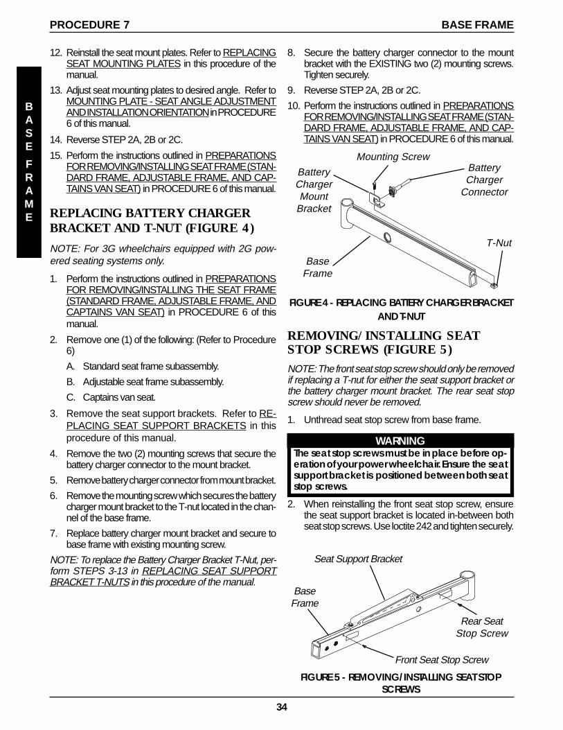
34
FIGURE 5 - REMOVING/INSTALLING SEAT STOPSCREWS
BaseFrame
Front Seat Stop Screw
Rear SeatStop Screw
Seat Support Bracket
REMOVING/INSTALLING SEATSTOP SCREWS (FIGURE 5)NOTE: The front seat stop screw should only be removedif replacing a T-nut for either the seat support bracket orthe battery charger mount bracket. The rear seat stopscrew should never be removed.
1. Unthread seat stop screw from base frame.
WARNINGThe seat stop screws must be in place before op-eration of your power wheelchair. Ensure the seatsupport bracket is positioned between both seatstop screws.
2. When reinstalling the front seat stop screw, ensurethe seat support bracket is located in-between bothseat stop screws. Use loctite 242 and tighten securely.
8. Secure the battery charger connector to the mountbracket with the EXISTING two (2) mounting screws.Tighten securely.
9. Reverse STEP 2A, 2B or 2C.
10. Perform the instructions outlined in PREPARATIONSFOR REMOVING/INSTALLING SEAT FRAME (STAN-DARD FRAME, ADJUSTABLE FRAME, AND CAP-TAINS VAN SEAT) in PROCEDURE 6 of this manual.
12. Reinstall the seat mount plates. Refer to REPLACINGSEAT MOUNTING PLATES in this procedure of themanual.
13. Adjust seat mounting plates to desired angle. Refer toMOUNTING PLATE - SEAT ANGLE ADJUSTMENTAND INSTALLATION ORIENTATION in PROCEDURE6 of this manual.
14. Reverse STEP 2A, 2B or 2C.
15. Perform the instructions outlined in PREPARATIONSFOR REMOVING/INSTALLING SEAT FRAME (STAN-DARD FRAME, ADJUSTABLE FRAME, AND CAP-TAINS VAN SEAT) in PROCEDURE 6 of this manual.
REPLACING BATTERY CHARGERBRACKET AND T-NUT (FIGURE 4)
NOTE: For 3G wheelchairs equipped with 2G pow-ered seating systems only.
1. Perform the instructions outlined in PREPARATIONSFOR REMOVING/INSTALLING THE SEAT FRAME(STANDARD FRAME, ADJUSTABLE FRAME, ANDCAPTAINS VAN SEAT) in PROCEDURE 6 of thismanual.
2. Remove one (1) of the following: (Refer to Procedure6)
A. Standard seat frame subassembly.
B. Adjustable seat frame subassembly.
C. Captains van seat.
3. Remove the seat support brackets. Refer to RE-PLACING SEAT SUPPORT BRACKETS in thisprocedure of this manual.
4. Remove the two (2) mounting screws that secure thebattery charger connector to the mount bracket.
5. Remove battery charger connector from mount bracket.
6. Remove the mounting screw which secures the batterycharger mount bracket to the T-nut located in the chan-nel of the base frame.
7. Replace battery charger mount bracket and secure tobase frame with existing mounting screw.
NOTE: To replace the Battery Charger Bracket T-Nut, per-form STEPS 3-13 in REPLACING SEAT SUPPORTBRACKET T-NUTS in this procedure of the manual.
FIGURE 4 - REPLACING BATTERY CHARGER BRACKETAND T-NUT
BatteryCharger
Connector
BatteryChargerMount
Bracket
BaseFrame
T-Nut
Mounting Screw
BASE FRAMEPROCEDURE 7
BASE
FRAME
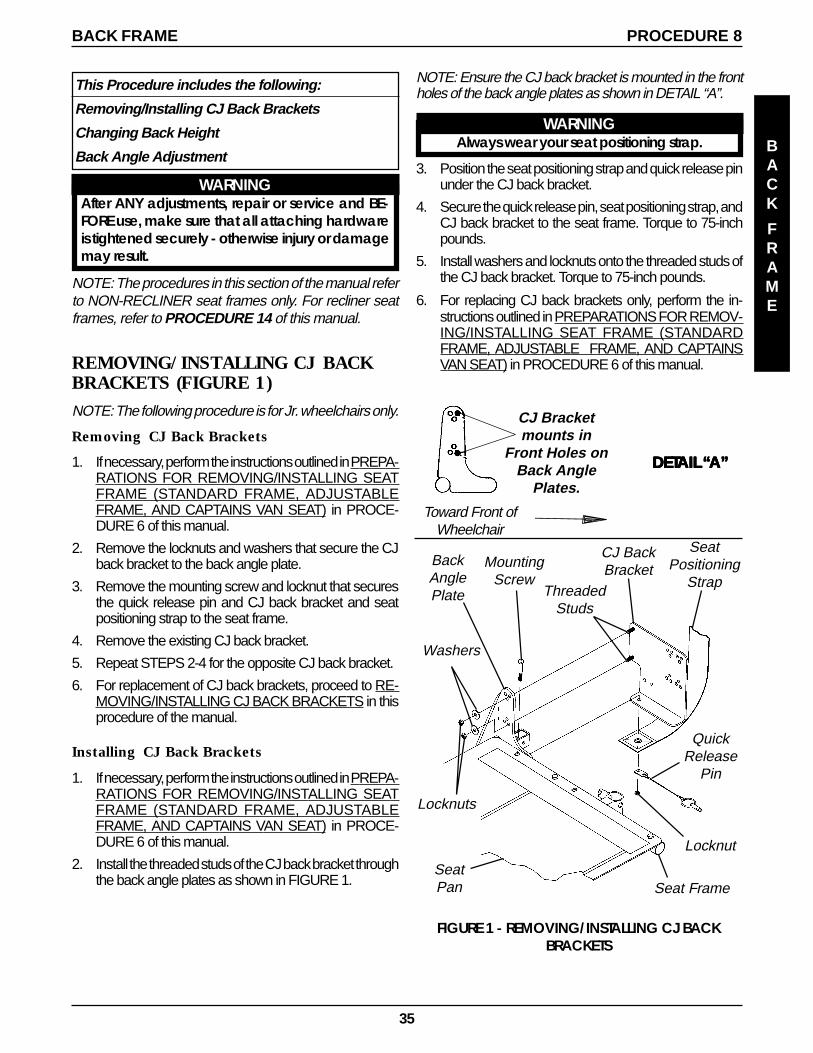
35
PROCEDURE 8
BACK
FRAME
This Procedure includes the following:
Removing/Installing CJ Back Brackets
Changing Back Height
Back Angle Adjustment
WARNINGAfter ANY adjustments, repair or service and BE-FORE use, make sure that all attaching hardwareis tightened securely - otherwise injury or damagemay result.
NOTE: The procedures in this section of the manual referto NON-RECLINER seat frames only. For recliner seatframes, refer to PROCEDURE 14 of this manual.
REMOVING/INSTALLING CJ BACKBRACKETS (FIGURE 1)NOTE: The following procedure is for Jr. wheelchairs only.
Removing CJ Back Brackets
1. If necessary, perform the instructions outlined in PREPA-RATIONS FOR REMOVING/INSTALLING SEATFRAME (STANDARD FRAME, ADJUSTABLEFRAME, AND CAPTAINS VAN SEAT) in PROCE-DURE 6 of this manual.
2. Remove the locknuts and washers that secure the CJback bracket to the back angle plate.
3. Remove the mounting screw and locknut that securesthe quick release pin and CJ back bracket and seatpositioning strap to the seat frame.
4. Remove the existing CJ back bracket.
5. Repeat STEPS 2-4 for the opposite CJ back bracket.
6. For replacement of CJ back brackets, proceed to RE-MOVING/INSTALLING CJ BACK BRACKETS in thisprocedure of the manual.
Installing CJ Back Brackets
1. If necessary, perform the instructions outlined in PREPA-RATIONS FOR REMOVING/INSTALLING SEATFRAME (STANDARD FRAME, ADJUSTABLEFRAME, AND CAPTAINS VAN SEAT) in PROCE-DURE 6 of this manual.
2. Install the threaded studs of the CJ back bracket throughthe back angle plates as shown in FIGURE 1.
BACK FRAME
NOTE: Ensure the CJ back bracket is mounted in the frontholes of the back angle plates as shown in DETAIL “A”.
WARNINGAlways wear your seat positioning strap.
3. Position the seat positioning strap and quick release pinunder the CJ back bracket.
4. Secure the quick release pin, seat positioning strap, andCJ back bracket to the seat frame. Torque to 75-inchpounds.
5. Install washers and locknuts onto the threaded studs ofthe CJ back bracket. Torque to 75-inch pounds.
6. For replacing CJ back brackets only, perform the in-structions outlined in PREPARATIONS FOR REMOV-ING/INSTALLING SEAT FRAME (STANDARDFRAME, ADJUSTABLE FRAME, AND CAPTAINSVAN SEAT) in PROCEDURE 6 of this manual.
MountingScrew
Locknut
QuickRelease
Pin
BackAnglePlate
Seat Frame
Washers
Locknuts
CJ BackBracket
SeatPositioning
Strap
FIGURE 1 - REMOVING/INSTALLING CJ BACKBRACKETS
Toward Front ofWheelchair
CJ Bracketmounts in
Front Holes onBack Angle
Plates.
DETDETDETDETDETAIL AIL AIL AIL AIL “““““A”A”A”A”A”
ThreadedStuds
SeatPan
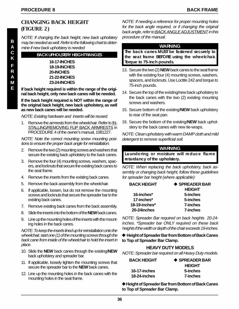
36
NOTE: If needing a reference for proper mounting holesfor the back angle required, or if changing the originalback angle, refer to BACK ANGLE ADJUSTMENT in thisprocedure of the manual.
WARNINGThe back canes MUST be fastened securely tothe seat frame BEFORE using the wheelchair.Torque to 75-inch pounds.
13. Secure the two (2) NEW back canes to the seat framewith the existing four (4) mounting screws, washers,spacers, and locknuts. Use Loctite 242 and torque to75-inch pounds.
14. Secure the top of the existing/new back upholstery tothe back canes with the two (2) existing mountingscrews and washers.
15. Secure bottom of the existing/NEW back upholsteryto rear of the seat pan.
16. Secure the bottom of the existing/NEW back uphol-stery to the back canes with new tie-wraps.
NOTE: Clean upholstery with warm DAMP cloth and milddetergent to remove superficial soil.
WARNINGLaundering or moisture will reduce flameretardancy of the upholstery.
NOTE: When replacing the back upholstery, back as-sembly or changing back height, follow these guidelinesfor spreader bar height (where applicable):
BACK HEIGHT u SPREADER BARHEIGHT
16-inches* 5-inches17-inches* 5-inches
18-19-inches* 7-inches20-24inches 7-inches
NOTE: Spreader Bar required on back heights 20-24-inches. *Spreader bar ONLY required on these backheights if the width or depth of the chair exceeds 19-inches.
u Height of Spreader Bar from Bottom of Back Canesto Top of Spreader Bar Clamp.
HEAVY DUTY MODELSNOTE: Spreader bar required on all Heavy Duty models.
BACK HEIGHT u SPREADER BARHEIGHT
16-17-inches 5-inches18-24-inches 7-inches
uHeight of Spreader Bar from Bottom of Back Canesto Top of Spreader Bar Clamp.
CHANGING BACK HEIGHT(FIGURE 2)
NOTE: If changing the back height, new back upholsterymay be needed as well. Refer to the following chart to deter-mine if new back upholstery is needed:
BACK UPHOLSTERY HEIGHT RANGES
16-17-INCHES18-19-INCHES20-INCHES21-22-INCHES23-24-INCHES
If back height required is within the range of the origi-nal back height, only new back canes will be needed.
If the back height required is NOT within the range ofthe original back height, new back upholstery, as wellas new back canes will be needed.
NOTE: Existing hardware and inserts will be reused.
1. Remove the armrests from the wheelchair. Refer to IN-STALLING/REMOVING FLIP BACK ARMRESTS inPROCEDURE 4 of the owner’s manual, 1081227.
NOTE: Note the correct mounting screw mounting posi-tions to ensure the proper back angle for reinstallation.
2. Remove the two (2) mounting screws and washers thatsecure the existing back upholstery to the back canes.
3. Remove the four (4) mounting screws, washers, spac-ers, and locknuts that secure the existing back canes tothe seat frame.
4. Remove the inserts from the existing back canes.
5. Remove the back assembly from the wheelchair.
6. If applicable, loosen, but do not remove the mountingscrews and locknuts that secure the spreader bar to theexisting back canes.
7. Remove existing back canes from the back assembly.
8. Slide the inserts into the bottom of the NEW back canes.
9. Line up the mounting holes of the inserts with the mount-ing holes in the back canes.
NOTE: To keep the inserts lined up for reinstallation onto thewheelchair, start one (1) of the mounting screws through theback cane from inside of the wheelchair to hold the insert inplace.
10. Slide the NEW back canes through the existing/NEWback upholstery and spreader bar.
11. If applicable, loosely tighten the mounting screws thatsecure the spreader bar to the NEW back canes.
12. Line up the mounting holes in the back canes with themounting holes in the seat frame.
BACK FRAMEPROCEDURE 8
BACK
FRAME
37
FIGURE 2 - CHANGING BACK HEIGHT
Locknut(STEPS 6,11)
Mounting ScrewTorque to 60 in/lbs
(STEPS 6,11)
Spreader Bar(STEPS 6,17)
MountingScrew
(STEPS 2, 14)
Washer(STEPS 2, 14)
BackUpholstery
Back Cane(STEPS 3, 10)
Insert(STEPS 4,8)
Seat Frame
Mounting ScrewsTorque to 75 in/lbs
(STEPS 3, 13)
Washers(STEPS 3, 13)
Mounting Screws(STEPS 3, 13)
Washers(STEPS 3, 13)
Spacers(STEPS 3, 13)
Locknuts(STEPS 3, 13)
Locknut(STEPS 6,11)
MountingScrew
(STEPS 6,11)
17. If necessary, reposition the spreader bar at the cor-rect height for the corresponding back height andtorque the mounting hardware to 60-inch pounds.
18. Reinstall the armrest onto the wheelchair. Refer toINSTALLING/REMOVING FLIP BACK ARMRESTSin PROCEDURE 4 of the owner’s manual, 1081227.
BACK FRAME PROCEDURE 8
BACK
FRAME
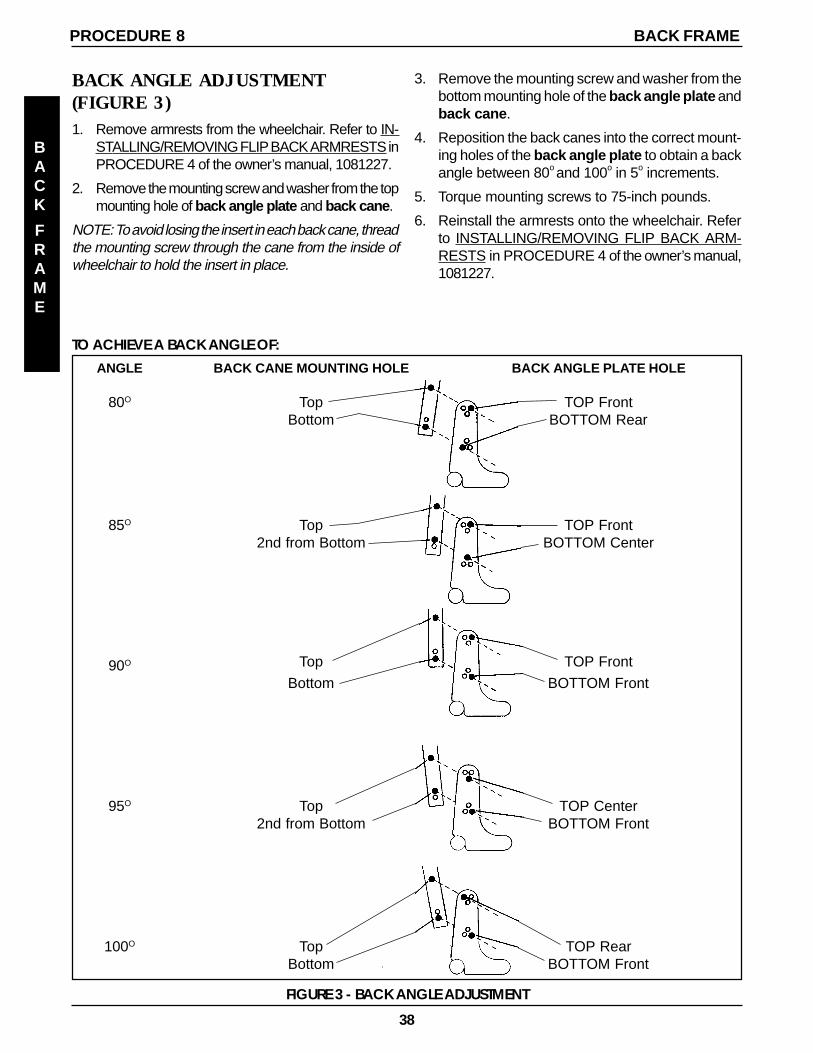
38
BACK ANGLE ADJUSTMENT(FIGURE 3)1. Remove armrests from the wheelchair. Refer to IN-
STALLING/REMOVING FLIP BACK ARMRESTS inPROCEDURE 4 of the owner’s manual, 1081227.
2. Remove the mounting screw and washer from the topmounting hole of back angle plate and back cane .
NOTE: To avoid losing the insert in each back cane, threadthe mounting screw through the cane from the inside ofwheelchair to hold the insert in place.
TO ACHIEVE A BACK ANGLE OF:ANGLE BACK CANE MOUNTING HOLE BACK ANGLE PLATE HOLE
80O Top TOP FrontBottom BOTTOM Rear
85O Top TOP Front2nd from Bottom BOTTOM Center
90O Top TOP Front
Bottom BOTTOM Front
95O Top TOP Center2nd from Bottom BOTTOM Front
100O Top TOP RearBottom BOTTOM Front
FIGURE 3 - BACK ANGLE ADJUSTMENT
3. Remove the mounting screw and washer from thebottom mounting hole of the back angle plate andback cane .
4. Reposition the back canes into the correct mount-ing holes of the back angle plate to obtain a backangle between 80o and 100o in 5o increments.
5. Torque mounting screws to 75-inch pounds.
6. Reinstall the armrests onto the wheelchair. Referto INSTALLING/REMOVING FLIP BACK ARM-RESTS in PROCEDURE 4 of the owner’s manual,1081227.
BACK FRAMEPROCEDURE 8
BACK
FRAME
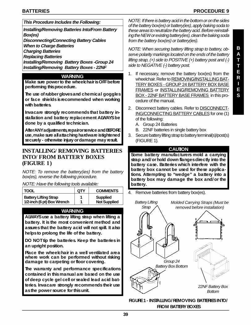
39
BATTERIES
BATTERIES PROCEDURE 9
This Procedure Includes the Following:
Installing/Removing Batteries Into/From BatteryBox(es)Disconnecting/Connecting Battery CablesWhen to Charge BatteriesCharging BatteriesReplacing BatteriesInstalling/Removing Battery Boxes -Group 24Installing/Removing Battery Boxes - 22NF
WARNINGMake sure power to the wheelchair is OFF beforeperforming this procedure.
The use of rubber gloves and chemical gogglesor face shields is recommended when workingwith batteries.
Invacare strongly recommends that battery in-stallation and battery replacement ALWAYS bedone by a qualified technician.After ANY adjustments, repair or service and BEFOREuse, make sure all attaching hardware is tightenedsecurely - otherwise injury or damage may result.
INSTALLING/REMOVING BATTERIESINTO/FROM BATTERY BOXES(FIGURE 1)NOTE: To remove the battery(ies) from the batterybox(es), reverse the following procedure.
NOTE: Have the following tools available:
TOOL QTY COMMENTS
Battery Lifting Strap 1 Supplied1/2-inch (6 pt) Box Wrench 1 Not Supplied
WARNINGALWAYS use a battery lifting strap when lifting abattery. It is the most convenient method andassures that the battery acid will not spill. It alsohelps to prolong the life of the battery.
DO NOT tip the batteries. Keep the batteries inan upright position.Place the wheelchair in a well ventilated areawhere work can be performed without riskingdamage to carpeting or floor covering.The warranty and performance specificationscontained in this manual are based on the useof deep cycle gel cell or sealed lead acid bat-teries. Invacare strongly recommends their useas the power source for this unit.
Battery LiftingStrap
Group 24Battery Box Bottom
Molded Carrying Straps (Must beremoved before installation)
FIGURE 1 - INSTALLING/REMOVING BATTERIES INTO/FROM BATTERY BOXES
NOTE: If there is battery acid in the bottom or on the sidesof the battery box(es) or battery(ies), apply baking soda tothese areas to neutralize the battery acid. Before reinstall-ing the NEW or existing battery(ies), clean the baking sodafrom the battery box(es) or battery(ies).
NOTE: When securing battery lifting strap to battery, ob-serve polarity markings located on the ends of the batterylifting strap, (+) side to POSITIVE (+) battery post and (-)side to NEGATIVE (-) battery post.
1. If necessary, remove the battery box(es) from thewheelchair. Refer to REMOVING/INSTALLING BAT-TERY BOXES - GROUP 24 BATTERY BOX BASEFRAMES or INSTALLING/REMOVING BATTERYBOX - 22NF BATTERY BASE FRAMES in this pro-cedure of the manual.
2. Disconnect battery cables. Refer to DISCONNECT-ING/CONNECTING BATTERY CABLES for one (1)of the following:A. Group 24 BatteriesB. 22NF batteries in single battery box
3. Secure battery lifting strap to battery terminal(s)/post(s)(FIGURE 1).
CAUTIONSome battery manufacturers mold a carryingstrap and/or hold down flanges directly into thebattery case. Batteries which interfere with thebattery box cannot be used for these applica-tions. Attempting to “wedge” a battery into abattery box may damage the box and/or thebattery.
4. Remove batteries from battery box(es).
22NF Battery BoxBottom
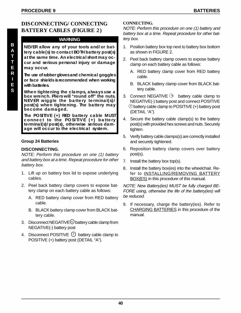
40
PROCEDURE 9 BATTERIES
BATTERIES
DISCONNECTING/CONNECTINGBATTERY CABLES (FIGURE 2)
WARNINGNEVER allow any of your tools and/or bat-tery cable(s) to contact BOTH battery post(s)at the same time. An electrical short may oc-cur and serious personal injury or damagemay occur.
The use of rubber gloves and chemical gogglesor face shields is recommended when workingwith batteries.When tightening the clamps, always use abox wrench. Pliers will “round off” the nuts.NEVER wiggle the battery terminal(s)/post(s) when tightening. The battery maybecome damaged.The POSITIVE (+) RED battery cable MUSTconnect to the POSITIVE (+) batteryterminal(s)/post(s), otherwise serious dam-age will occur to the electrical system.
CONNECTING.NOTE: Perform this procedure on one (1) battery andbattery box at a time. Repeat procedure for other bat-tery box.
1. Position battery box top next to battery box bottomas shown in FIGURE 2.
2. Peel back battery clamp covers to expose batteryclamp on each battery cable as follows:
A. RED battery clamp cover from RED batterycable.
B. BLACK battery clamp cover from BLACK bat-tery cable.
3. Connect NEGATIVE N battery cable clamp toNEGATIVE(-) battery post and connect POSITIVEP battery cable clamp to POSITIVE (+) battery post(DETAIL “A”).
4. Secure the battery cable clamp(s) to the batterypost(s) with provided hex screws and nuts. Securelytighten.
5. Verify battery cable clamps(s) are correctly installedand securely tightened.
6. Reposition battery clamp covers over batterypost(s).
7. Install the battery box top(s).
8. Install the battery box(es) into the wheelchair. Re-fer to INSTALLING/REMOVING BATTERYBOX(ES) in this procedure of this manual.
NOTE: New Battery(ies) MUST be fully charged BE-FORE using, otherwise the life of the battery(ies) willbe reduced.
9. If necessary, charge the battery(ies). Refer toCHARGING BATTERIES in this procedure of themanual.
Group 24 Batteries
DISCONNECTING.NOTE: Perform this procedure on one (1) batteryand battery box at a time. Repeat procedure for otherbattery box.
1. Lift up on battery box lid to expose underlyingcables.
2. Peel back battery clamp covers to expose bat-tery clamp on each battery cable as follows:
A. RED battery clamp cover from RED batterycable.
B. BLACK battery clamp cover from BLACK bat-tery cable.
3. Disconnect NEGATIVE N battery cable clamp fromNEGATIVE(-) battery post
4. Disconnect POSITIVE P battery cable clamp toPOSITIVE (+) battery post (DETAIL “A”).
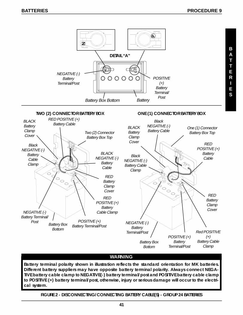
41
P
N
FIGURE 2 - DISCONNECTING/CONNECTING BATTERY CABLE(S) - GROUP 24 BATTERIES
Battery Box Bottom
POSITIVE(+)
BatteryTerminal/
Post
NEGATIVE (-)Battery
Terminal/Post
Battery
ONE (1) CONNECTOR BATTERY BOXTWO (2) CONNECTOR BATTERY BOX
BLACKBatteryClampCover
REDBatteryClampCover
Red POSITIVE(+)
Battery CableClamp
BlackNEGATIVE (-)Battery Cable
Clamp
BlackNEGATIVE (-)Battery Cable
REDPOSITIVE (+)
BatteryCable
One (1) ConnectorBattery Box Top
Battery BoxBottom
BLACKBatteryClampCover
REDBatteryClampCover
REDPOSITIVE (+)
BatteryCable Clamp
BlackNEGATIVE (-)
BatteryCableClamp
RED POSITIVE (+) Battery Cable
BLACKNEGATIVE (-)
BatteryCable
Two (2) ConnectorBattery Box Top
Battery BoxBottom
DETAIL “A”
NEGATIVE (-)Battery
Terminal/PostPOSITIVE (+)
BatteryTerminal/Post
NEGATIVE (-)Battery Terminal/
Post POSITIVE (+)Battery Terminal/Post
BATTERIES PROCEDURE 9
BATTERIES
WARNINGBattery terminal polarity shown in illustration reflects the standard orientation for MK batteries.Different battery suppliers may have opposite battery terminal polarity. Always connect NEGA-TIVE battery cable clamp to NEGATIVE(-) battery terminal/post and POSITIVE battery cable clampto POSITIVE (+) battery terminal/post, otherwise, injury or serious damage will occur to the electri-cal system.
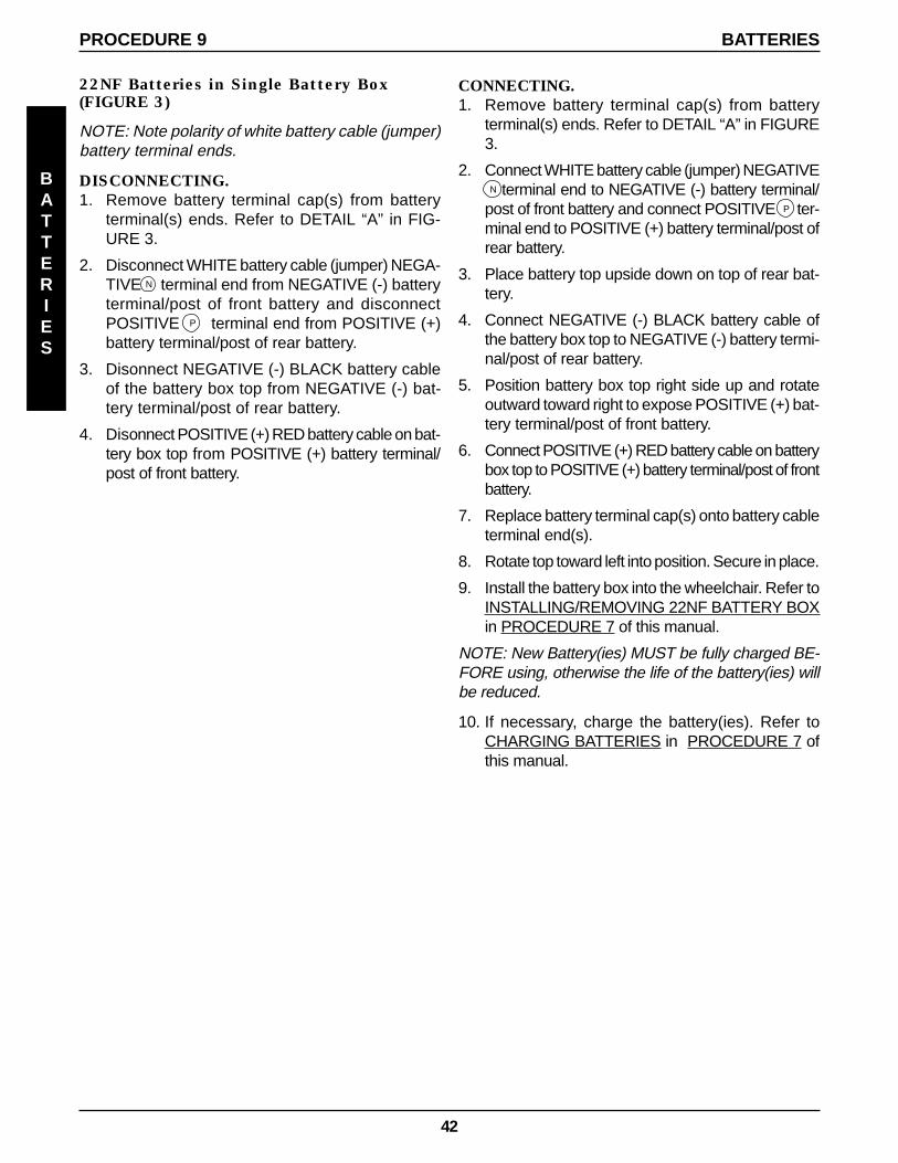
42
22NF Batteries in Single Battery Box(FIGURE 3)
NOTE: Note polarity of white battery cable (jumper)battery terminal ends.
DISCONNECTING.1. Remove battery terminal cap(s) from battery
terminal(s) ends. Refer to DETAIL “A” in FIG-URE 3.
2. Disconnect WHITE battery cable (jumper) NEGA-TIVE N terminal end from NEGATIVE (-) batteryterminal/post of front battery and disconnectPOSITIVE P terminal end from POSITIVE (+)battery terminal/post of rear battery.
3. Disonnect NEGATIVE (-) BLACK battery cableof the battery box top from NEGATIVE (-) bat-tery terminal/post of rear battery.
4. Disonnect POSITIVE (+) RED battery cable on bat-tery box top from POSITIVE (+) battery terminal/post of front battery.
BATTERIESPROCEDURE 9
BATTERIES
CONNECTING.1. Remove battery terminal cap(s) from battery
terminal(s) ends. Refer to DETAIL “A” in FIGURE3.
2. Connect WHITE battery cable (jumper) NEGATIVE N terminal end to NEGATIVE (-) battery terminal/post of front battery and connect POSITIVE P ter-minal end to POSITIVE (+) battery terminal/post ofrear battery.
3. Place battery top upside down on top of rear bat-tery.
4. Connect NEGATIVE (-) BLACK battery cable ofthe battery box top to NEGATIVE (-) battery termi-nal/post of rear battery.
5. Position battery box top right side up and rotateoutward toward right to expose POSITIVE (+) bat-tery terminal/post of front battery.
6. Connect POSITIVE (+) RED battery cable on batterybox top to POSITIVE (+) battery terminal/post of frontbattery.
7. Replace battery terminal cap(s) onto battery cableterminal end(s).
8. Rotate top toward left into position. Secure in place.
9. Install the battery box into the wheelchair. Refer toINSTALLING/REMOVING 22NF BATTERY BOXin PROCEDURE 7 of this manual.
NOTE: New Battery(ies) MUST be fully charged BE-FORE using, otherwise the life of the battery(ies) willbe reduced.
10. If necessary, charge the battery(ies). Refer toCHARGING BATTERIES in PROCEDURE 7 ofthis manual.
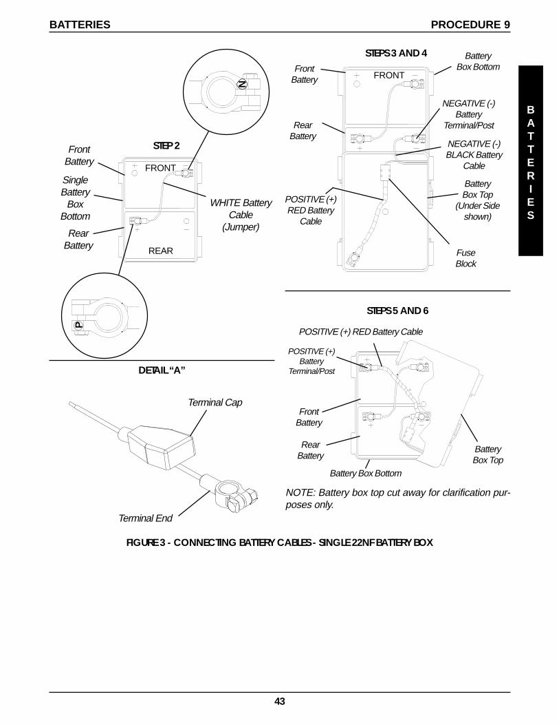
43
STEPS 3 AND 4
BatteryBox Top
(Under Sideshown)
NEGATIVE (-)BLACK Battery
Cable
FrontBattery
RearBattery
STEPS 5 AND 6
BatteryBox Top
FrontBattery
BatteryBox Bottom
FRONT
POSITIVE (+)RED Battery
Cable
FuseBlock
POSITIVE (+) RED Battery Cable
Battery Box Bottom
RearBattery
NEGATIVE (-)Battery
Terminal/Post
POSITIVE (+)Battery
Terminal/Post
NOTE: Battery box top cut away for clarification pur-poses only.
FIGURE 3 - CONNECTING BATTERY CABLES - SINGLE 22NF BATTERY BOX
STEP 2
SingleBattery
BoxBottom
WHITE BatteryCable
(Jumper)
FrontBattery
RearBattery
FRONT
REARN
P
DETAIL “A”
Terminal Cap
Terminal End
BATTERIES PROCEDURE 9
BATTERIES

44
MKIV- A JOYSTICK MKIV- A+ JOYSTICK
Battery DischargeIndicator (BDI) (in LCD
Readout)Battery Discharge
Indicator (BDI)
WHEN TO CHARGE BATTERIES(FIGURE 4)The Battery Discharge Indicator (BDI) is a bar graphdisplay located on the MKIV joystick. It will keep youinformed as to power availability. A visual warning isgiven before the power becomes too low to operate thewheelchair. At full charge the two (2) LEFT segmentsand the farthest RIGHT segment of the bar graph willbe illuminated. As the battery becomes discharged, thefarthest RIGHT segment will progressively move to theLEFT until only the last two (2) bars (LEFT) are illumi-nated. At this level the last two (2) bars (LEFT) will startto Flash ON and OFF to indicate that the end user shouldcharge the batteries as soon as possible.
CAUTIONAlways charge new batteries before initial useor battery life will be reduced.
NOTE: As a general rule, batteries should be rechargeddaily to assure the longest possible life and minimize therequired charging time. Plan to recharge the batterieswhen it is anticipated the wheelchair will not be used fora long period of time.
The range per battery charge using recommended bat-teries should be approximately 5 to 9 hours of typicaloperation. Extensive use on inclines may substantiallyreduce per charge mileage.
Description and Use of Battery Chargers
The charger automatically reduces the charge from aninitially high rate to a zero reading at a fully charged con-dition. If left unattended, the charger should automati-cally shut-off when full charge is obtained.
There are some basic concepts which will help youunderstand this automatic process. They are:
The amount of electrical current drawn within a giventime to charge a battery is called the “charge rate”. If, dueto usage, the charge stored in the battery is low, the chargerate is high, as indicated by the green light on the charger.Initially, the green light will stay illuminated for a shortperiod of time followed by a longer period of off time. Asa charge builds up, the charge rate is reduced, and thegreen light will stay illuminated for a longer period of timefollowed by a shorter off time.
WARNINGNEVER leave the charger unattended when thecharger circuit breaker is tripping ON and OFF. Acondition between the battery charger and bat-teries exists. Contact an Invacare dealer.
BATTERIES
BATTERIESPROCEDURE 9
FIGURE 4 - WHEN TO CHARGE BATTERIES
MKIV- RII JOYSTICK(TORQUE SP ONLY)
Battery Discharge Indicator(BDI)
CHARGING BATTERIES (FIGURE 5)NOTE: New batteries MUST be fully charged prior toinitial use of the wheelchair.
WARNINGNever attempt to recharge the batteries by at-taching cables directly to the battery terminalsor clamps. Always use the recharging plug lo-cated on the side of the wheelchair frame.
DO NOT attempt to recharge the batteries andoperate the power wheelchair at the same time.
During use and charging, unsealed batteries willvent hydrogen gas which is explosive in the rightconcentration with air.
NOTE: If performing the charging procedures indepen-dently, READ and CAREFULLY follow the individualinstructions for each charger (supplied or purchased).
NOTE: If charging instructions are not supplied, con-sult a qualified service technician for proper procedures.
Required Items:
TOOL QUANTITY COMMENTSBattery Charger 1 SupplieduExtension Cord 1 Not Supplied
u (3-prong plug, 15 ampere current rating; industrial type)
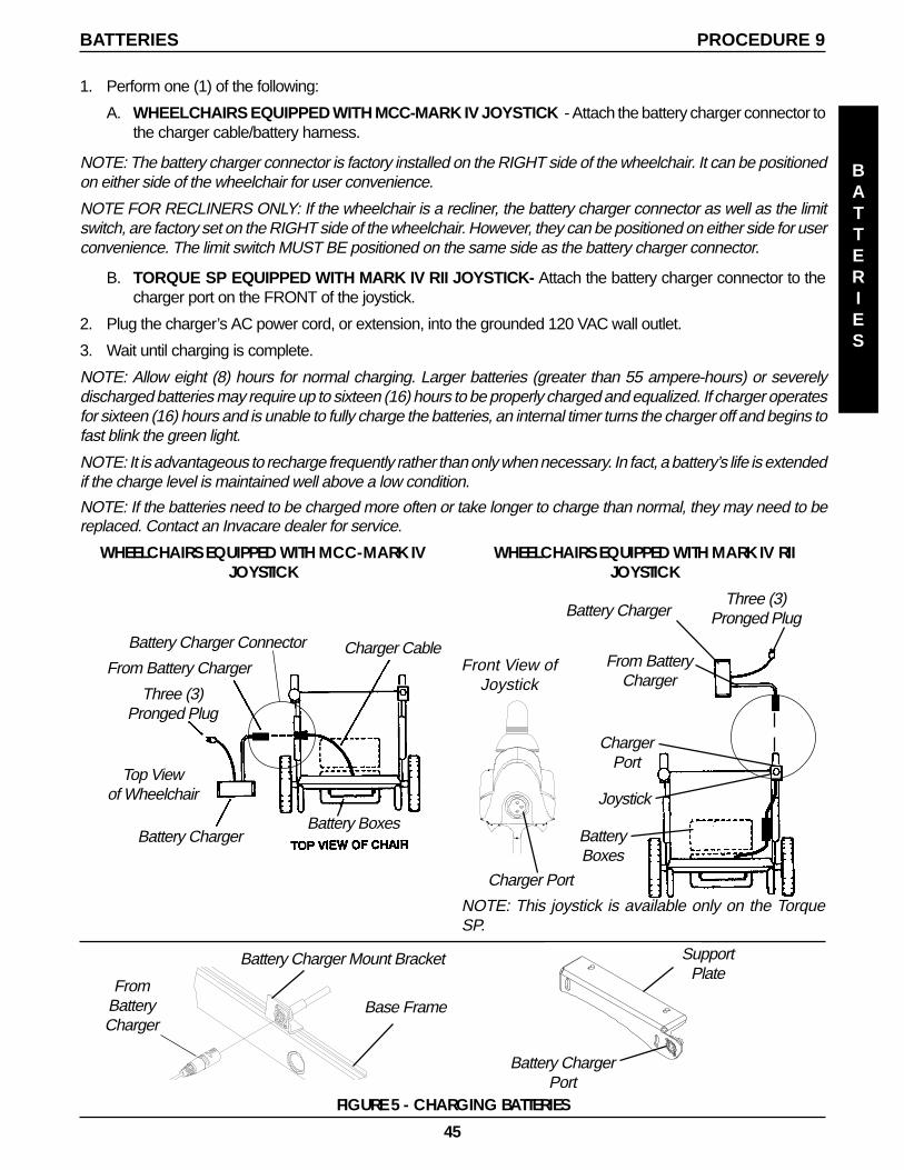
45
BATTERIES PROCEDURE 9
FromBatteryCharger
Battery Charger Connector
From Battery Charger
Three (3)Pronged Plug
Battery Charger
Charger Cable
Battery Boxes
Top Viewof Wheelchair
Base Frame
Battery Charger Mount Bracket
WHEELCHAIRS EQUIPPED WITH MCC-MARK IVJOYSTICK
SupportPlate
Battery ChargerPort
Front View ofJoystick
Charger Port
Battery ChargerThree (3)
Pronged Plug
From BatteryCharger
ChargerPort
Joystick
BatteryBoxes
NOTE: This joystick is available only on the TorqueSP.
WHEELCHAIRS EQUIPPED WITH MARK IV RIIJOYSTICK
FIGURE 5 - CHARGING BATTERIES
BATTERIES
1. Perform one (1) of the following:
A. WHEELCHAIRS EQUIPPED WITH MCC-MARK IV JOYSTICK - Attach the battery charger connector tothe charger cable/battery harness.
NOTE: The battery charger connector is factory installed on the RIGHT side of the wheelchair. It can be positionedon either side of the wheelchair for user convenience.
NOTE FOR RECLINERS ONLY: If the wheelchair is a recliner, the battery charger connector as well as the limitswitch, are factory set on the RIGHT side of the wheelchair. However, they can be positioned on either side for userconvenience. The limit switch MUST BE positioned on the same side as the battery charger connector.
B. TORQUE SP EQUIPPED WITH MARK IV RII JOYSTICK- Attach the battery charger connector to thecharger port on the FRONT of the joystick.
2. Plug the charger’s AC power cord, or extension, into the grounded 120 VAC wall outlet.
3. Wait until charging is complete.
NOTE: Allow eight (8) hours for normal charging. Larger batteries (greater than 55 ampere-hours) or severelydischarged batteries may require up to sixteen (16) hours to be properly charged and equalized. If charger operatesfor sixteen (16) hours and is unable to fully charge the batteries, an internal timer turns the charger off and begins tofast blink the green light.
NOTE: It is advantageous to recharge frequently rather than only when necessary. In fact, a battery’s life is extendedif the charge level is maintained well above a low condition.
NOTE: If the batteries need to be charged more often or take longer to charge than normal, they may need to bereplaced. Contact an Invacare dealer for service.
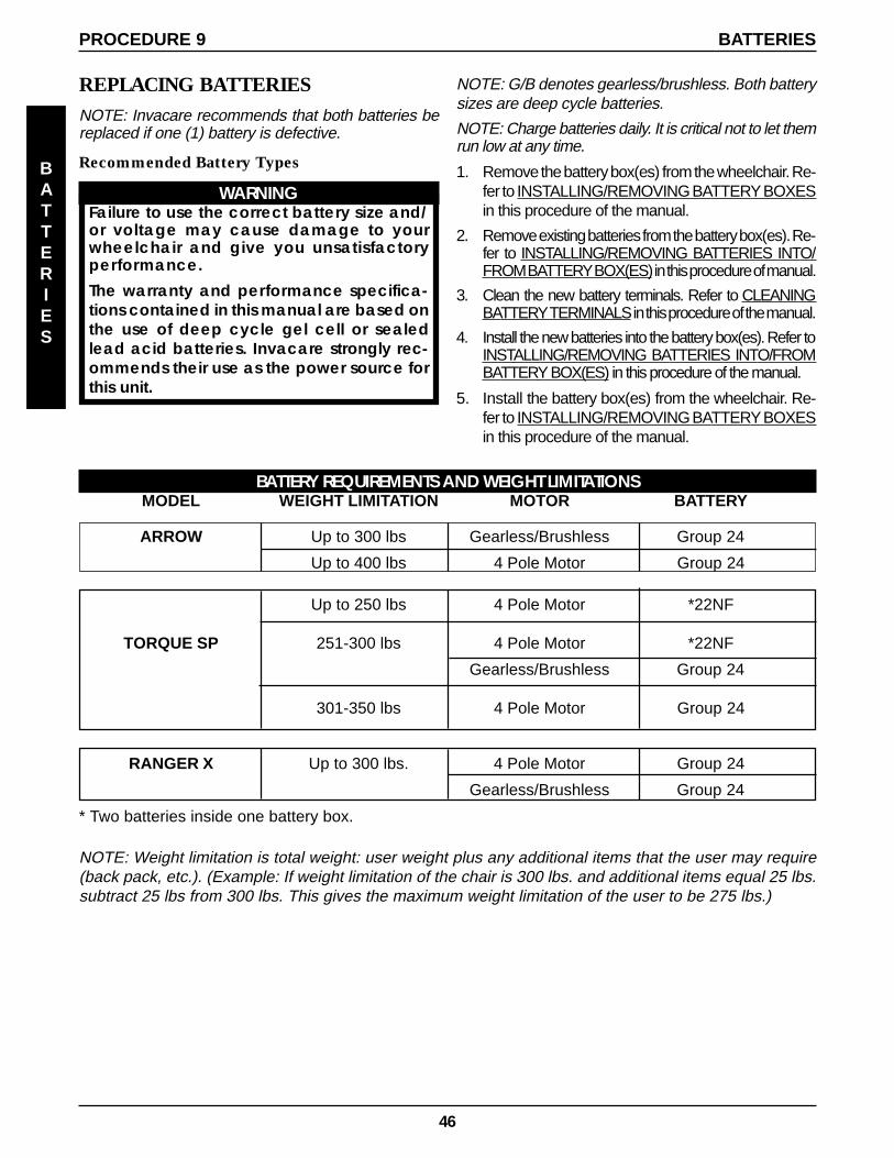
46
REPLACING BATTERIESNOTE: Invacare recommends that both batteries bereplaced if one (1) battery is defective.
Recommended Battery Types
WARNINGFailure to use the correct battery size and/or voltage may cause damage to yourwheelchair and give you unsatisfactoryperformance.
The warranty and performance specifica-tions contained in this manual are based onthe use of deep cycle gel cell or sealedlead acid batteries. Invacare strongly rec-ommends their use as the power source forthis unit.
BATTERIES
BATTERIESPROCEDURE 9
NOTE: G/B denotes gearless/brushless. Both batterysizes are deep cycle batteries.
NOTE: Charge batteries daily. It is critical not to let themrun low at any time.
1. Remove the battery box(es) from the wheelchair. Re-fer to INSTALLING/REMOVING BATTERY BOXESin this procedure of the manual.
2. Remove existing batteries from the battery box(es). Re-fer to INSTALLING/REMOVING BATTERIES INTO/FROM BATTERY BOX(ES) in this procedure of manual.
3. Clean the new battery terminals. Refer to CLEANINGBATTERY TERMINALS in this procedure of the manual.
4. Install the new batteries into the battery box(es). Refer toINSTALLING/REMOVING BATTERIES INTO/FROMBATTERY BOX(ES) in this procedure of the manual.
5. Install the battery box(es) from the wheelchair. Re-fer to INSTALLING/REMOVING BATTERY BOXESin this procedure of the manual.
BATTERY REQUIREMENTS AND WEIGHT LIMITATIONSMODEL WEIGHT LIMITATION MOTOR BA TTERY
* Two batteries inside one battery box.
Up to 250 lbs 4 Pole Motor *22NF
TORQUE SP 251-300 lbs 4 Pole Motor *22NF
Gearless/Brushless Group 24
301-350 lbs 4 Pole Motor Group 24
RANGER X Up to 300 lbs. 4 Pole Motor Group 24
Gearless/Brushless Group 24
ARROW Up to 300 lbs Gearless/Brushless Group 24
Up to 400 lbs 4 Pole Motor Group 24
NOTE: Weight limitation is total weight: user weight plus any additional items that the user may require(back pack, etc.). (Example: If weight limitation of the chair is 300 lbs. and additional items equal 25 lbs.subtract 25 lbs from 300 lbs. This gives the maximum weight limitation of the user to be 275 lbs.)
47
PROCEDURE 9
BATTERIES
Cleaning Battery Terminals
WARNINGMost batteries are not sold with instructions. How-ever, warnings are frequently noted on the cellcaps. Read them carefully.
DO NOT allow the liquid in the battery to comein contact with skin, clothes or other possessions.It is a form of acid and harmful or damagingburns may result. Should the liquid touch yourskin, wash the area IMMEDIATELY and thoroughlywith cool water. In serious cases or if eye con-tact is made, seek medical attention IMMEDI-ATELY.
1. Examine battery clamps and terminals for corrosion.
2. Verify the plastic caps are in place over battery cellholes.
3. Clean terminals and inside battery clamps by usinga battery cleaning tool, wire brush, or medium gradesand paper.
NOTE: Upon completion, areas should be shiny, notdull.
4. Carefully dust off all metal particles.
REMOVING/INSTALLING GROUP 24BATTERY BOXES FORWHEELCHAIRS NOT EQUIPPEDWITH VENT TRAY (FIGURE 6)
WARNINGEach battery weighs 51 pounds. Use proper lift-ing techniques (lift with your legs) to avoid injury.
Removing
1. Place the wheelchair in a well ventilated area wherework can be performed without risking damage tocarpeting or floor covering.
2. Verify the joystick ON/OFF switch is in the OFF posi-tion.
3. Rotate the levers of the battery retainer assemblyto the unlocked position.
4. Lift battery retainer assembly up off the mountingscrews that secure the shocks to the base frame.
NOTE: For gearless/brushless motors, ensure that themotor lock levers are in the engaged (drive) position.Refer to PROCEDURE 9.
5. Slide one (1) connector battery box along the sub-frame and remove from the wheelchair.
6. Slide the two (2) connector battery box along the sub-frame and remove from the wheelchair.
Installing
1. Place the wheelchair in a well ventilated area wherework can be performed without risking damage to car-peting or floor covering.
2. Verify the joystick ON/OFF switch is in the OFF posi-tion.
3. Secure the battery box carrying strap to the lid of thetwo (2) connector battery box.
4. Place two (2) connector battery box onto the batterysub-frame assembly with guide pins facing the insideof the wheelchair.
5. Slide the two (2) connector battery box along the sub-frame until its guide pins are engaged in the sub-frameconnector.
NOTE: Visually inspect to ensure the connection is prop-erly made. Connectors MUST be fully engaged.
NOTE: Make certain that the battery box carrying strap ispositioned on top of the battery box and will not interferewith the one (1) battery box guide pins when engaging theconnector on the one (1) battery box lid.
6. Secure the battery box carrying strap to the lid of theone (1) connector battery box.
7. Place one (1) connector battery box onto battery sub-frame.
8. Slide one (1) connector battery box along the sub-frame until its guide pins are engaged in the connec-tor of the two (2) connector battery box.
NOTE: Visually inspect to ensure the connection is prop-erly made. Connectors MUST be fully engaged.
9. Place the battery retainer assembly on head por-tion of the mounting screws that secure the shocksto the base frame.
CAUTIONThe battery retainer assembly MUST be lockedsecurely to hold the battery boxes firmly inplace or battery box connectors may be dam-aged causing erratic wheelchair operation.
10. Rotate the levers of the battery retainer assemblyto the locked position.
BATTERIES
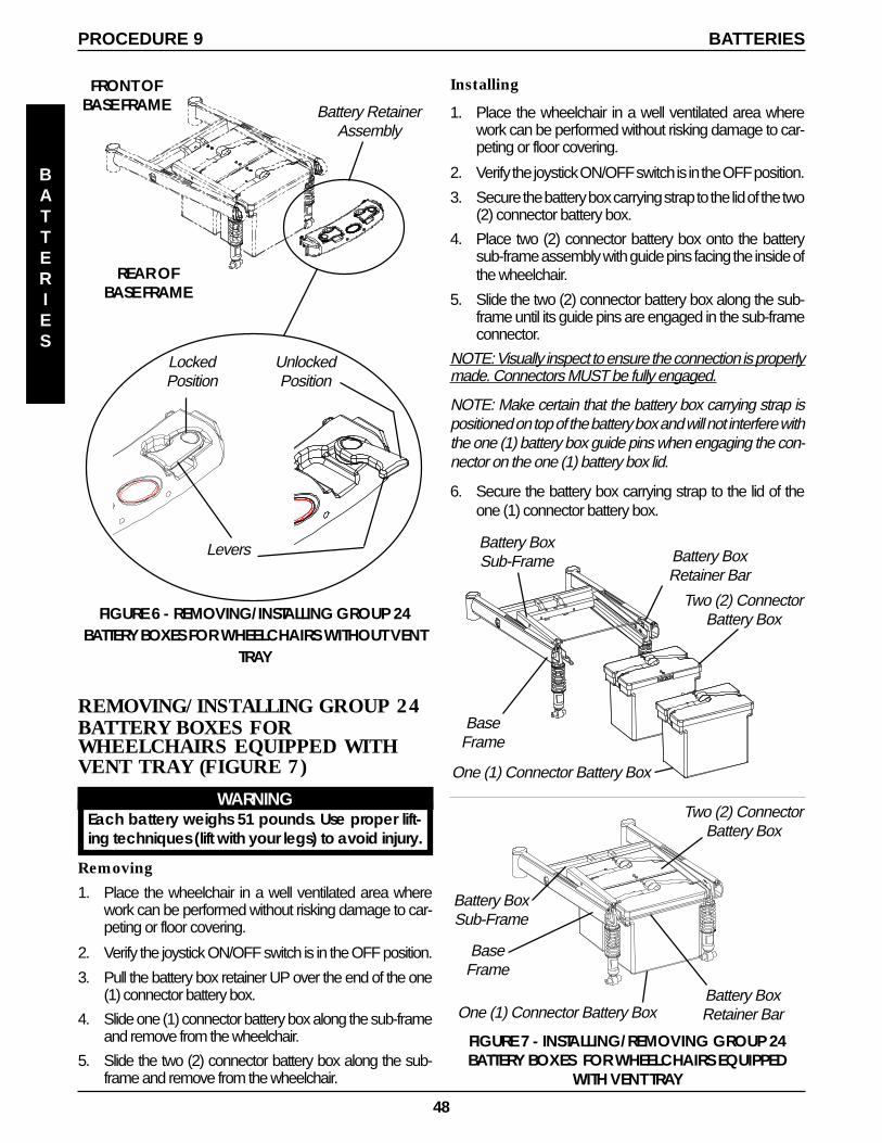
48
BATTERIES
BATTERIESPROCEDURE 9
FIGURE 6 - REMOVING/INSTALLING GROUP 24BATTERY BOXES FOR WHEELCHAIRS WITHOUT VENT
TRAY
REAR OFBASE FRAME
LockedPosition
UnlockedPosition
FRONT OFBASE FRAME Battery Retainer
Assembly
Levers
REMOVING/INSTALLING GROUP 24BATTERY BOXES FORWHEELCHAIRS EQUIPPED WITHVENT TRAY (FIGURE 7)
WARNINGEach battery weighs 51 pounds. Use proper lift-ing techniques (lift with your legs) to avoid injury.
Removing
1. Place the wheelchair in a well ventilated area wherework can be performed without risking damage to car-peting or floor covering.
2. Verify the joystick ON/OFF switch is in the OFF position.
3. Pull the battery box retainer UP over the end of the one(1) connector battery box.
4. Slide one (1) connector battery box along the sub-frameand remove from the wheelchair.
5. Slide the two (2) connector battery box along the sub-frame and remove from the wheelchair.
FIGURE 7 - INSTALLING/REMOVING GROUP 24BATTERY BOXES FOR WHEELCHAIRS EQUIPPED
WITH VENT TRAY
Battery BoxRetainer Bar
Installing
1. Place the wheelchair in a well ventilated area wherework can be performed without risking damage to car-peting or floor covering.
2. Verify the joystick ON/OFF switch is in the OFF position.
3. Secure the battery box carrying strap to the lid of the two(2) connector battery box.
4. Place two (2) connector battery box onto the batterysub-frame assembly with guide pins facing the inside ofthe wheelchair.
5. Slide the two (2) connector battery box along the sub-frame until its guide pins are engaged in the sub-frameconnector.
NOTE: Visually inspect to ensure the connection is properlymade. Connectors MUST be fully engaged.
NOTE: Make certain that the battery box carrying strap ispositioned on top of the battery box and will not interfere withthe one (1) battery box guide pins when engaging the con-nector on the one (1) battery box lid.
6. Secure the battery box carrying strap to the lid of theone (1) connector battery box.
One (1) Connector Battery Box
Two (2) ConnectorBattery Box
BaseFrame
Battery BoxSub-Frame
Battery BoxRetainer BarOne (1) Connector Battery Box
Two (2) ConnectorBattery Box
BaseFrame
Battery BoxSub-Frame
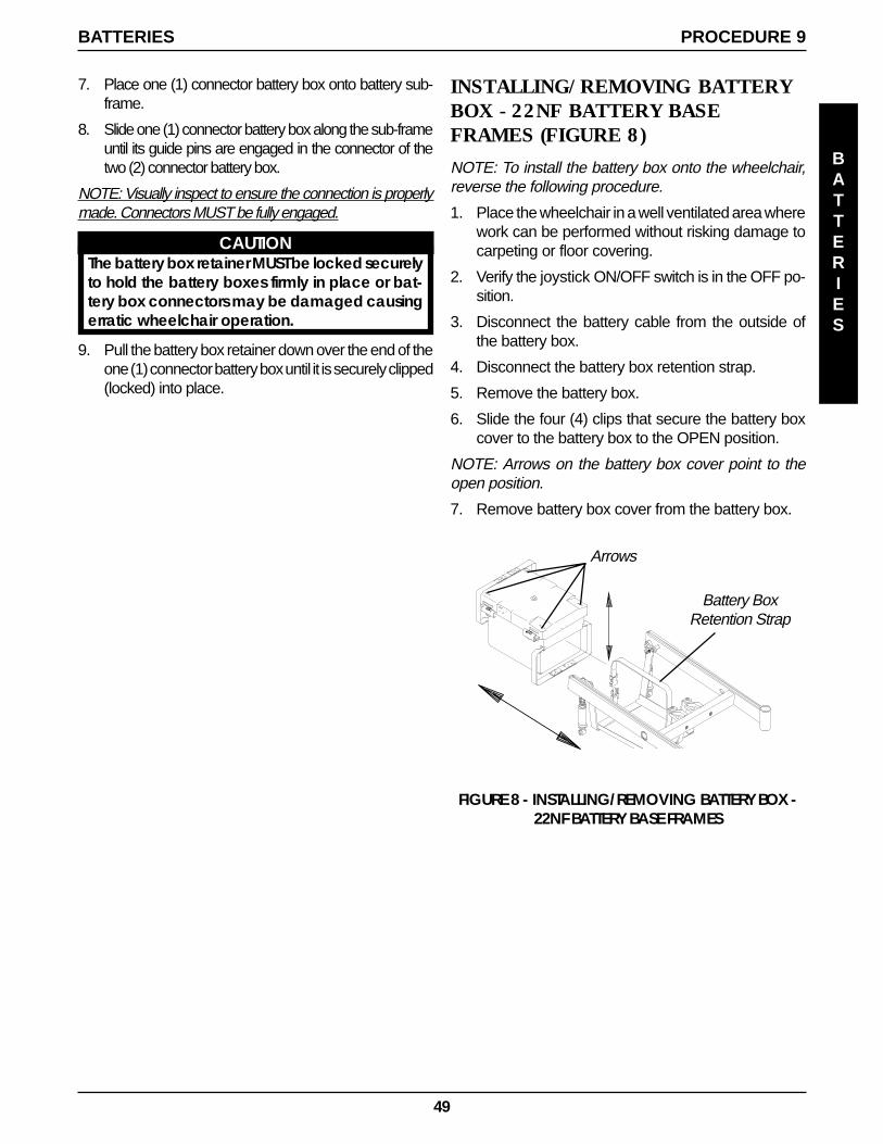
49
INSTALLING/REMOVING BATTERYBOX - 22NF BATTERY BASEFRAMES (FIGURE 8)
NOTE: To install the battery box onto the wheelchair,reverse the following procedure.
1. Place the wheelchair in a well ventilated area wherework can be performed without risking damage tocarpeting or floor covering.
2. Verify the joystick ON/OFF switch is in the OFF po-sition.
3. Disconnect the battery cable from the outside ofthe battery box.
4. Disconnect the battery box retention strap.
5. Remove the battery box.
6. Slide the four (4) clips that secure the battery boxcover to the battery box to the OPEN position.
NOTE: Arrows on the battery box cover point to theopen position.
7. Remove battery box cover from the battery box.
FIGURE 8 - INSTALLING/REMOVING BATTERY BOX -22NF BATTERY BASE FRAMES
Battery BoxRetention Strap
Arrows
7. Place one (1) connector battery box onto battery sub-frame.
8. Slide one (1) connector battery box along the sub-frameuntil its guide pins are engaged in the connector of thetwo (2) connector battery box.
NOTE: Visually inspect to ensure the connection is properlymade. Connectors MUST be fully engaged.
CAUTIONThe battery box retainer MUST be locked securelyto hold the battery boxes firmly in place or bat-tery box connectors may be damaged causingerratic wheelchair operation.
9. Pull the battery box retainer down over the end of theone (1) connector battery box until it is securely clipped(locked) into place.
PROCEDURE 9
BATTERIES
BATTERIES
50
REMOVING/INSTALLING THEWIRING HARNESS (FIGURE 1)
Group 24 Batteries
REMOVING.1. Remove the battery box(es). Refer to INSTALLING/RE-
MOVING GROUP 24 BATTERY BOXES in PROCE-DURE 9 of this manual.
2. Remove the two mounting screws and locknuts thatsecure the wiring harness bracket to the base frame(DETAIL “A”).
3. Perform one (1) of the following sections:
WHEELCHAIRS WITH MOTOR/GEARBOX ASSEMBLYA. Cut tie-wraps A and B that secure the two (2)
motor/controller connections and the controller/wiring harness connection (BLUE connectors)together (DETAIL “B”).
B. Cut tie-wrap C that secures the battery chargercable, motor connector cable, controller connec-tor cable, and wiring harness cable to the baseframe (DETAIL “B”).
WHEELCHAIRS WITH GEARLESS/BRUSHLESS MOTOR
A. Cut tie-wrap A that secures the battery chargercable to the base frame (DETAIL “C”).
NOTE: For STEPS 4-6 refer to Detail “B” or “C”.
4. Disconnect the battery harness/charger cable (BLUE)from the controller connector (BLUE).
5. Remove the two mounting screws that secure thecharger cable to the mounting bracket.
6. Remove the wiring harness.
This Procedure includes the following:
Removing/Installing the Wiring Harness
Adjusting Limit Switch
WARNINGAfter ANY adjustments, repair or service and BE-FORE use, make sure that all attaching hardwareis tightened securely - otherwise injury or dam-age may result.
PROCEDURE 10 WIRING HARNESS
WIRING
HARNESS
Installing
1. Install NEW wiring harness w/bracket to the rearof the sub-frame and torque mounting screws to160-inch pounds (DETAIL “A”).
2. Secure the charger cable to the mounting bracketwith the two (2) mounting screws. Securely tighten(DETAIL “B” OR “C”).
3. Connect the battery harness/charger cable (BLUE)to the controller connector (BLUE) (DETAIL “B” or“C”).
4. Perform one (1) of the following sections:
WHEELCHAIRS WHEELCHAIRS WHEELCHAIRS WHEELCHAIRS WHEELCHAIRS WITH MOWITH MOWITH MOWITH MOWITH MOTTTTTOR/GEARBOOR/GEARBOOR/GEARBOOR/GEARBOOR/GEARBOXXXXXASSEMBLASSEMBLASSEMBLASSEMBLASSEMBLYYYYY
A. Group the two (2) motor/controller connectionstogether along with the controller/wiring har-ness connection (BLUE) and secure with TIE-WRAPS A and B (DETAIL “B”).
B. Secure the Wiring Harness Cable, BatteryCharger Cable, Controller Connector Cable,and Motor Connector Cable to the suspensionarm with TIE-WRAP C (DETAIL “B”).
WHEELCHAIRS WITH GEARLESS/BRUSHLESS MOTOROPTION:
A. Secures the battery charger cable to the baseframe with TIE-WRAP A (DETAIL “C”).
5. Reinstall the battery box(es). Refer to INSTALLING/REMOVING GROUP 24 BATTERY BOXES in PRO-CEDURE 9 of this manual.
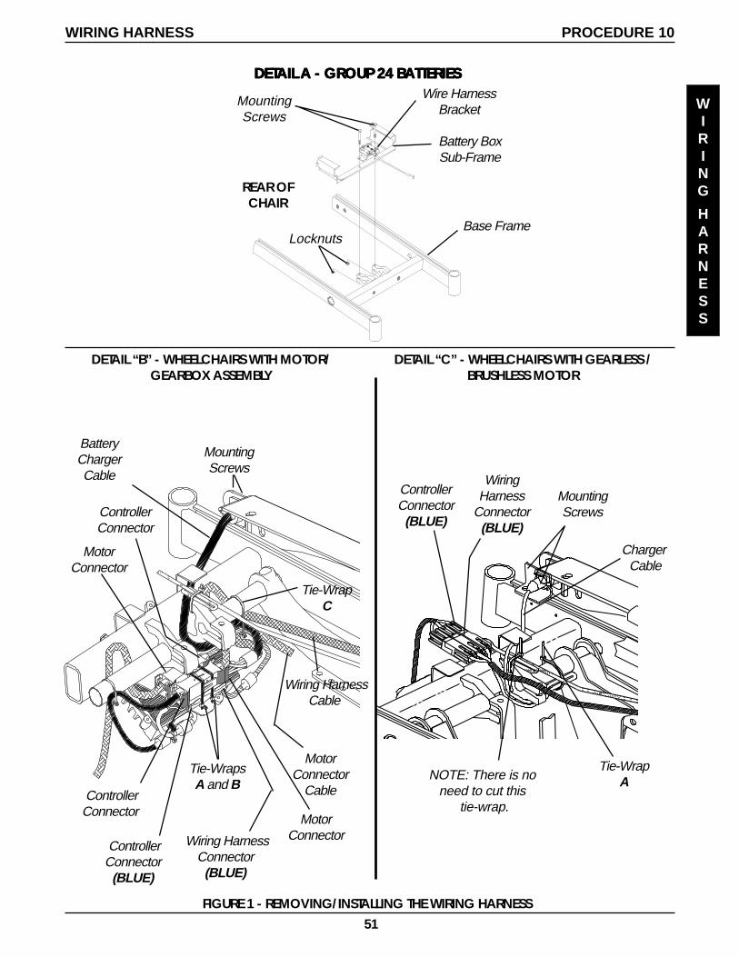
51
REAR OFCHAIR
MountingScrews
Locknuts
Tie-WrapsA and B
Wiring HarnessConnector
(BLUE)
ControllerConnector
(BLUE)
PROCEDURE 10
WIRING
HARNESS
MotorConnector
ControllerConnector
MountingScrews
BatteryChargerCable
MotorConnector
ControllerConnector
WiringHarness
Connector(BLUE)
ControllerConnector(BLUE)
DETAIL “C” - WHEELCHAIRS WITH GEARLESS /BRUSHLESS MOTOR
Tie-WrapANOTE: There is no
need to cut this tie-wrap.
WIRING HARNESS
MountingScrews
Charger Cable
FIGURE 1 - REMOVING/INSTALLING THE WIRING HARNESS
DETDETDETDETDETAIL AIL AIL AIL AIL A - GRA - GRA - GRA - GRA - GROUP 24 BOUP 24 BOUP 24 BOUP 24 BOUP 24 BAAAAATTERIESTTERIESTTERIESTTERIESTTERIES
DETAIL “B” - WHEELCHAIRS WITH MOTOR/GEARBOX ASSEMBLY
Tie-WrapC
Wiring HarnessCable
MotorConnector
Cable
Wire HarnessBracket
Battery BoxSub-Frame
Base Frame

52
22NF Batteries
REMOVING.1. Remove the battery box(es). Refer to INSTALLING/
REMOVING 22NF BATTERY BOX in PROCEDURE9 of this manual.
2. Cut the tie wrap that secures the rear portion of thewiring harness and joystick cable to the rear of theseat frame (DETAIL “A”).
3. Perform one (1) of the following sections:
WHEELCHAIRS WITH MOTOR/GEARBOX ASSEMBLYA. Cut tie-wraps A and B that secure the two (2)
motor/controller connections and the controller/wiring harness connection (BLUE connectors)together (DETAIL “B”).
B. Cut tie-wrap C that secures the battery chargercable, motor connector cable, controller connec-tor cable, and wiring harness cable to the baseframe (DETAIL “B”).
WHEELCHAIRS WITH GEARLESS/BRUSHLESS MOTOR
A. Cut tie-wrap A that secures the battery chargercable to the base frame (DETAIL “C”).
NOTE: For STEPS 4-6 refer to Detail “B” or “C”.
4. Disconnect the battery harness/charger cable (BLUE)from the controller connector (BLUE).
5. Remove the two mounting screws that secure thecharger cable to the mounting bracket.
6. Remove the wiring harness.
Installing
1. Secure the charger cable to the mounting bracketwith the two (2) mounting screws. Securely tighten(DETAIL “B” or “C”).
2. Connect the battery harness/charger cable (BLUE)to the controller connector (BLUE) (DETAIL “B” or“C”).
3. Perform one (1) of the following sections:
WHEELCHAIRS WITH MOTOR/GEARBOX ASSEMBLY
A. Group the two (2) motor/controller connectionstogether along with the controller/wiring har-ness connection (BLUE) and secure with TIE-WRAPS A and B (DETAIL “B”).
B. Secure the Wiring Harness Cable, BatteryCharger Cable, Controller Connector Cable,and Motor Connector Cable to the suspensionarm with TIE-WRAP C (DETAIL “B”).
WHEELCHAIRS WITH GEARLESS/BRUSHLESS MOTOROPTION:
A. Secures the battery charger cable to the baseframe with TIE-WRAP A (DETAIL “C”).
4. Tie-wrap NEW wiring harness and joystick cable tothe rear of the seat frame (DETAIL “A”).
5. Reinstall the battery box(es). Refer to INSTALLING/REMOVING 22NF BATTERY BOX in PROCEDURE9 of this manual.
PROCEDURE 10 WIRING HARNESS
WIRING
HARNESS
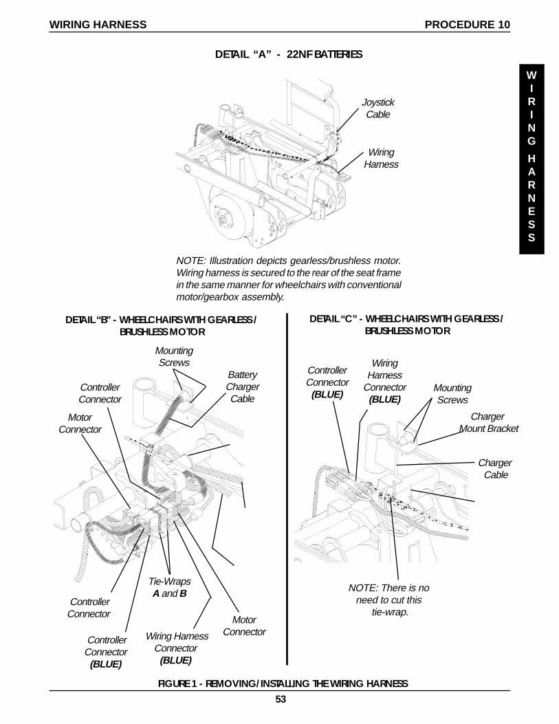
53
Tie-WrapsA and B
Wiring HarnessConnector
(BLUE)
ControllerConnector
(BLUE)
MotorConnector
ControllerConnector
MountingScrews
BatteryChargerCable
MotorConnector
ControllerConnector
DETAIL “A” - 22NF BATTERIES
Charger Mount Bracket
WiringHarness
Connector(BLUE)
ControllerConnector(BLUE)
DETAIL “C” - WHEELCHAIRS WITH GEARLESS /BRUSHLESS MOTOR
NOTE: There is noneed to cut this
tie-wrap.
NOTE: Illustration depicts gearless/brushless motor.Wiring harness is secured to the rear of the seat framein the same manner for wheelchairs with conventionalmotor/gearbox assembly.
JoystickCable
WiringHarness
MountingScrews
Charger Cable
FIGURE 1 - REMOVING/INSTALLING THE WIRING HARNESS
DETAIL “B” - WHEELCHAIRS WITH GEARLESS /BRUSHLESS MOTOR
PROCEDURE 10WIRING HARNESS
WIRING
HARNESS
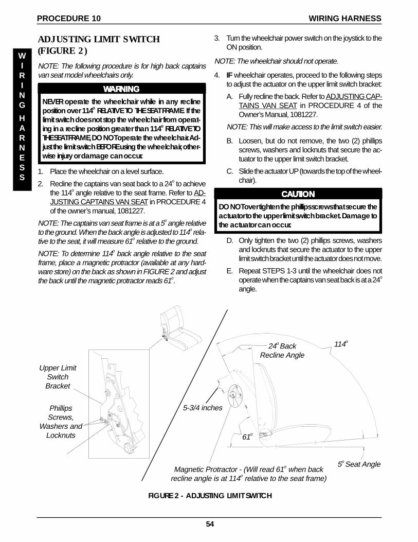
54
ADJUSTING LIMIT SWITCH(FIGURE 2)
NOTE: The following procedure is for high back captainsvan seat model wheelchairs only.
WWWWWARNINGARNINGARNINGARNINGARNINGNEVER operate the wheelchair while in any reclineposition over 114o RELATIVE TO THE SEAT FRAME. If thelimit switch does not stop the wheelchair from operat-ing in a recline position greater than 114o RELATIVE TOTHE SEAT FRAME, DO NOT operate the wheelchair. Ad-just the limit switch BEFORE using the wheelchair, other-wise injury or damage can occur.
1. Place the wheelchair on a level surface.
2. Recline the captains van seat back to a 24o to achievethe 114o angle relative to the seat frame. Refer to AD-JUSTING CAPTAINS VAN SEAT in PROCEDURE 4of the owner’s manual, 1081227.
NOTE: The captains van seat frame is at a 5o angle relativeto the ground. When the back angle is adjusted to 114o rela-tive to the seat, it will measure 61o relative to the ground.
NOTE: To determine 114o back angle relative to the seatframe, place a magnetic protractor (available at any hard-ware store) on the back as shown in FIGURE 2 and adjustthe back until the magnetic protractor reads 61o.
3. Turn the wheelchair power switch on the joystick to theON position.
NOTE: The wheelchair should not operate.
4. IF wheelchair operates, proceed to the following stepsto adjust the actuator on the upper limit switch bracket:
A. Fully recline the back. Refer to ADJUSTING CAP-TAINS VAN SEAT in PROCEDURE 4 of theOwner’s Manual, 1081227.
NOTE: This will make access to the limit switch easier.
B. Loosen, but do not remove, the two (2) phillipsscrews, washers and locknuts that secure the ac-tuator to the upper limit switch bracket.
C. Slide the actuator UP (towards the top of the wheel-chair).
CCCCCAAAAAUTIONUTIONUTIONUTIONUTIONDO NOT over tighten the phillips screws that secure theactuator to the upper limit switch bracket. Damage tothe actuator can occur.
D. Only tighten the two (2) phillips screws, washersand locknuts that secure the actuator to the upperlimit switch bracket until the actuator does not move.
E. Repeat STEPS 1-3 until the wheelchair does notoperate when the captains van seat back is at a 24o
angle.
FIGURE 2 - ADJUSTING LIMIT SWITCH
24o BackRecline Angle
61o
Magnetic Protractor - (Will read 61o when backrecline angle is at 114o relative to the seat frame)
Upper LimitSwitchBracket
PhillipsScrews,
Washers andLocknuts
5-3/4 inches
5o Seat Angle
114o
PROCEDURE 10 WIRING HARNESS
WIRING
HARNESS
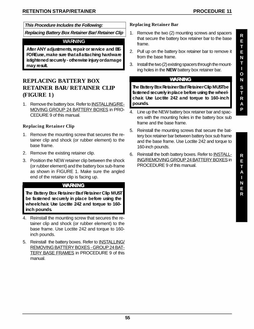
55
REPLACING BATTERY BOXRETAINER BAR/RETAINER CLIP(FIGURE 1)
1. Remove the battery box. Refer to INSTALLING/RE-MOVING GROUP 24 BATTERY BOXES in PRO-CEDURE 9 of this manual.
Replacing Retainer Clip
1. Remove the mounting screw that secures the re-tainer clip and shock (or rubber element) to thebase frame.
2. Remove the existing retainer clip.
3. Position the NEW retainer clip between the shock(or rubber element) and the battery box sub-frameas shown in FIGURE 1. Make sure the angledend of the retainer clip is facing up.
WWWWWARNINGARNINGARNINGARNINGARNINGThe Battery Box Retainer Bar/Retainer Clip MUSTbe fastened securely in place before using thewheelchair. Use Loctite 242 and torque to 160-inch pounds.
4. Reinstall the mounting screw that secures the re-tainer clip and shock (or rubber element) to thebase frame. Use Loctite 242 and torque to 160-inch pounds.
5. Reinstall the battery boxes. Refer to INSTALLING/REMOVING BATTERY BOXES - GROUP 24 BAT-TERY BASE FRAMES in PROCEDURE 9 of thismanual.
RETENTION STRAP/RETAINER PROCEDURE 11
This Procedure Includes the Following:
Replacing Battery Box Retainer Bar/ Retainer Clip
WARNINGAfter ANY adjustments, repair or service and BE-FORE use, make sure that all attaching hardwareis tightened securely - otherwise injury or damagemay result.
RETENTION
STRAP
RETAINER
Replacing Retainer Bar
1. Remove the two (2) mounting screws and spacersthat secure the battery box retainer bar to the baseframe.
2. Pull up on the battery box retainer bar to remove itfrom the base frame.
3. Install the two (2) existing spacers through the mount-ing holes in the NEW battery box retainer bar.
WWWWWARNINGARNINGARNINGARNINGARNINGThe Battery Box Retainer Bar/Retainer Clip MUST befastened securely in place before using the wheel-chair. Use Loctite 242 and torque to 160-inchpounds.
4. Line up the NEW battery box retainer bar and spac-ers with the mounting holes in the battery box subframe and the base frame.
5. Reinstall the mounting screws that secure the bat-tery box retainer bar between battery box sub frameand the base frame. Use Loctite 242 and torque to160-inch pounds.
6. Reinstall the both battery boxes. Refer to INSTALL-ING/REMOVING GROUP 24 BATTERY BOXES inPROCEDURE 9 of this manual.
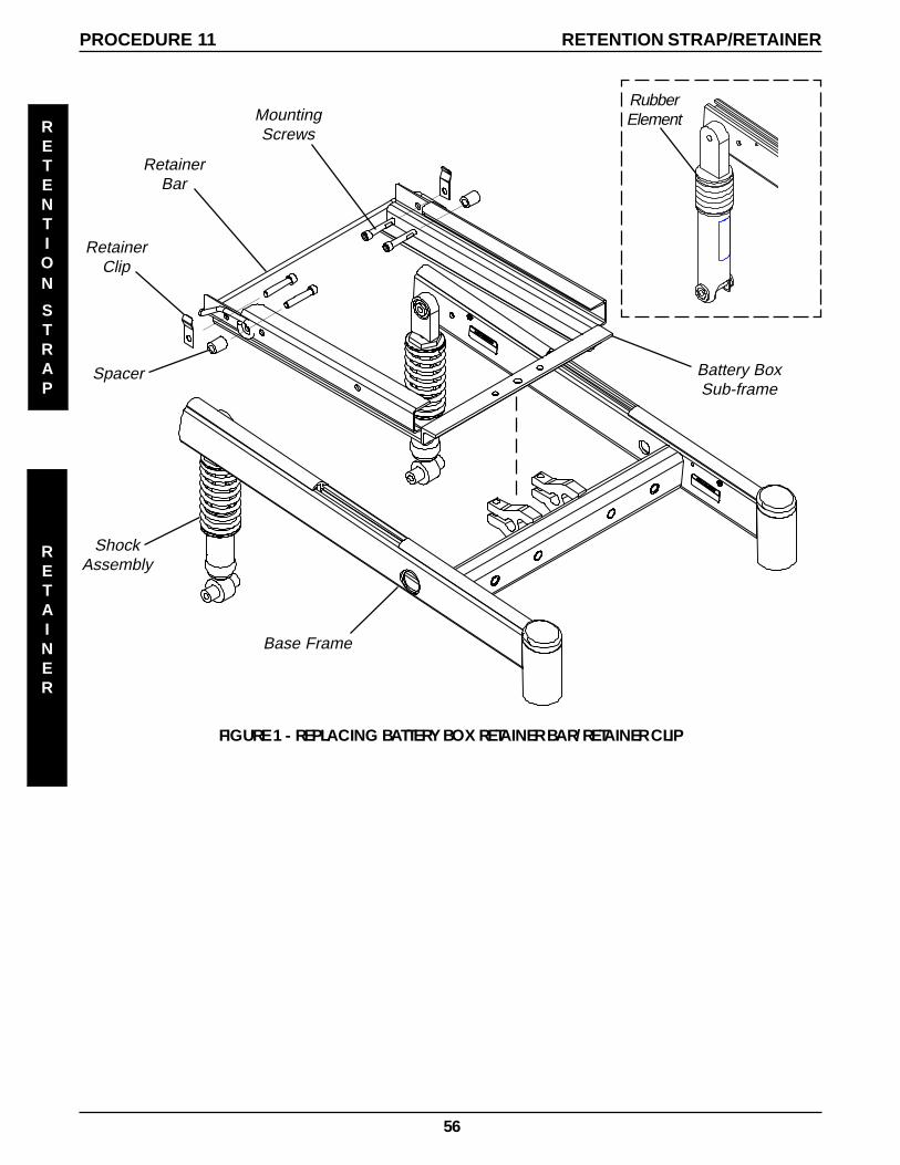
56
RetainerClip
MountingScrews
Battery BoxSub-frame
Base Frame
RetainerBar
ShockAssembly
Spacer
PROCEDURE 11
FIGURE 1 - REPLACING BATTERY BOX RETAINER BAR/RETAINER CLIP
RETENTION STRAP/RETAINER
RubberElementR
ETENTION
STRAP
RETAINER
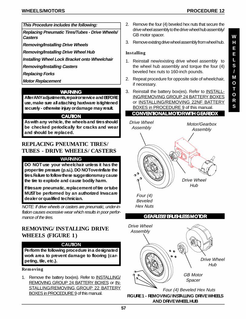
57
PROCEDURE 12WHEELS/MOTORS
WHEELS/MOTORS
This Procedure includes the following:
Replacing Pneumatic Tires/Tubes - Drive Wheels/Casters
Removing/Installing Drive Wheels
Removing/Installing Drive Wheel Hub
Installing Wheel Lock Bracket onto Wheelchair
Removing/Installing Casters
Replacing Forks
Motor Replacement
WWWWWARNINGARNINGARNINGARNINGARNINGAfter ANY adjustments, repair or service and BEFOREuse, make sure all attaching hardware is tightenedsecurely - otherwise injury or damage may result.
CCCCCAAAAAUTIONUTIONUTIONUTIONUTIONAs with any vehicle, the wheels and tires shouldbe checked periodically for cracks and wearand should be replaced.
Four (4)BeveledHex Nuts
Drive WheelAssembly
Drive WheelHub
Motor/GearboxAssembly
FIGURE 1 - REMOVING/INSTALLING DRIVE WHEELSAND DRIVE WHEEL HUB
2. Remove the four (4) beveled hex nuts that secure thedrive wheel assembly to the drive wheel hub assembly/GB motor spacer.
3. Remove existing drive wheel assembly from wheel hub.
Installing
1. Reinstall new/existing drive wheel assembly tothe wheel hub assembly and torque the four (4)beveled hex nuts to 160-inch pounds.
2. Repeat procedure for opposite side of wheelchair,if necessary.
3. Reinstall the battery box(es). Refer to INSTALL-ING/REMOVING GROUP 24 BATTERY BOXESor INSTALLING/REMOVING 22NF BATTERYBOXES in PROCEDURE 9 of this manual.CONVENTIONAL MOCONVENTIONAL MOCONVENTIONAL MOCONVENTIONAL MOCONVENTIONAL MOTTTTTOR OR OR OR OR WITH GEARBOWITH GEARBOWITH GEARBOWITH GEARBOWITH GEARBOXXXXX
GEARLESS/BRGEARLESS/BRGEARLESS/BRGEARLESS/BRGEARLESS/BRUSHLESS MOUSHLESS MOUSHLESS MOUSHLESS MOUSHLESS MOTTTTTOROROROROR
REPLACING PNEUMATIC TIRES/TUBES - DRIVE WHEELS/CASTERS
WARNINGDO NOT use your wheelchair unless it has theproper tire pressure (p.s.i.). DO NOT overinflate thetires. Failure to follow these suggestions may causethe tire to explode and cause bodily harm.
If tires are pneumatic, replacement of tire or tubeMUST be performed by an authorized Invacaredealer or qualified technician.
NOTE: If drive wheels or casters are pneumatic, under-in-flation causes excessive wear which results in poor perfor-mance of the tires.
REMOVING/INSTALLING DRIVEWHEELS (FIGURE 1)
CAUTIONPerform the following procedure in a designatedwork area to prevent damage to flooring (car-peting, tile, etc.).
Removing
1. Remove the battery box(es). Refer to INSTALLING/REMOVING GROUP 24 BATTERY BOXES or IN-STALLING/REMOVING GROUP 22 BATTERYBOXES in PROCEDURE 9 of this manual.
Four (4) Beveled Hex Nuts
Drive WheelAssembly
GB MotorSpacer
Drive WheelHub
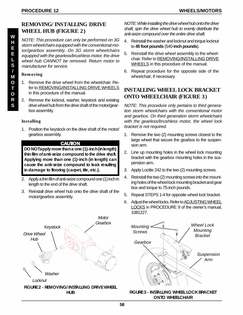
58
REMOVING/INSTALLING DRIVEWHEEL HUB (FIGURE 2)
NOTE: This procedure can only be performed on 3Gstorm wheelchairs equipped with the conventional mo-tor/gearbox assembly. On 3G storm wheelchairsequipped with the gearless/brushless motor, the drivewheel hub CANNOT be removed. Return motor tomanufacturer for service.
Removing
1. Remove the drive wheel from the wheelchair. Re-fer to REMOVING/INSTALLING DRIVE WHEELSin this procedure of the manual.
2. Remove the locknut, washer, keystock and existingdrive wheel hub from the drive shaft of the motor/gear-box assembly.
Installing
1. Position the keystock on the drive shaft of the motor/gearbox assembly.
CCCCCAAAAAUTIONUTIONUTIONUTIONUTIONDO NOT apply more than a one (1)-inch (in length)thin film of anti-seize compound to the drive shaft.Applying more than one (1)-inch (in length) cancause the anti-seize compound to leak resultingin damage to flooring (carpet, tile, etc.).
2. Apply a thin film of anti-seize compound one (1) inch inlength to the end of the drive shaft.
3. Reinstall drive wheel hub onto the drive shaft of themotor/gearbox assembly.
PROCEDURE 12 WHEELS/MOTORS
WHEELS/MOTORS
Locknut
Washer
Keystock
Drive WheelHub
FIGURE 2 - REMOVING/INSTALLING DRIVE WHEELHUB
MotorGearbox
INSTALLING WHEEL LOCK BRACKETONTO WHEELCHAIR (FIGURE 3)
NOTE: This procedure only pertains to third genera-tion storm wheelchairs with the conventional motorand gearbox. On third generation storm wheelchairswith the gearless/brushless motor, the wheel lockbracket is not required.
1. Remove the two (2) mounting screws closest to thelarge wheel that secure the gearbox to the suspen-sion arm.
2. Line up mounting holes in the wheel lock mountingbracket with the gearbox mounting holes in the sus-pension arm.
3. Apply Loctite 242 to the two (2) mounting screws.
4. Reinstall the two (2) mounting screws into the mount-ing holes of the wheel lock mounting bracket and gearbox and torque to 75-inch pounds.
5. Repeat STEPS 1-4 for opposite wheel lock bracket.
6. Adjust the wheel locks. Refer to ADJUSTING WHEELLOCKS in PROCEDURE 9 of the owner’s manual,1081227.
NOTE: While installing the drive wheel hub onto the driveshaft, spin the drive wheel hub to evenly distribute theanti-seize compound over the entire drive shaft.
4. Reinstall the washer and locknut and torque locknutto 45 foot pounds (540-inch pounds ).
5. Reinstall the drive wheel assembly to the wheel-chair. Refer to REMOVING/INSTALLING DRIVEWHEELS in this procedure of the manual.
6. Repeat procedure for the opposite side of thewheelchair, if necessary.
Gearbox
Wheel LockMountingBracket
MountingScrews
FIGURE 3 - INSTALLING WHEEL LOCK BRACKETONTO WHEELCHAIR
SuspensionArm
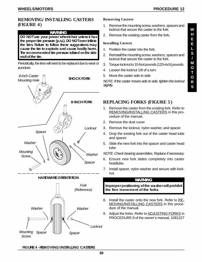
59
REPLACING FORKS (FIGURE 5)1. Remove the caster from the existing fork. Refer to
REMOVING/INSTALLING CASTERS in this pro-cedure of the manual.
2. Remove the dust cover.
3. Remove the locknut, nylon washer, and spacer.
4. Drop the existing fork out of the caster head tubeand spacer.
5. Slide the new fork into the spacer and caster headtube.
NOTE: Check bearing assemblies. Replace if necessary.
6. Ensure new fork slides completely into casterheadtube.
7. Install spacer, nylon washer and secure with lock-nut.
WWWWWARNINGARNINGARNINGARNINGARNINGImproper positioning of the washer will prohibitthe free movement of the forks.
8. Install the caster onto the new fork. Refer to RE-MOVING/INSTALLING CASTERS in this proce-dure of the manual.
9. Adjust the forks. Refer to ADJUSTING FORKS inPROCEDURE 9 of the owner’s manual, 1081227
Removing Casters
1. Remove the mounting screw, washers, spacers andlocknut that secure the caster to the fork.
2. Remove the existing caster from the fork.
Installing Casters
1. Position the caster into the fork.
2. Reinstall the mounting screw, washers, spacers andlocknut that secure the caster to the fork.
3. Torque locknut to 10-foot pounds (120-inch) pounds.
4. Loosen the locknut 1/8 of a turn.
5. Move the caster side to side.
NOTE: If the caster moves side to side, tighten the locknutslightly.
FIGURE 4 -REMOVING/INSTALLING CASTERS
MountingScrew
Washer
Spacer
Spacer
Washer
Locknut
8-INCH FORK
SHOCK FORK
HARDWARE ORIENTATION
Fork(Reference)
8-inch CasterMounting Hole
MountingScrew
Washer
Spacer Spacer
Washer
Locknut
REMOVING/INSTALLING CASTERS(FIGURE 4)
WWWWWARNINGARNINGARNINGARNINGARNINGDO NOT use your power wheelchair unless it hasthe proper tire pressure (p.s.i.). DO NOT over-inflatethe tires. Failure to follow these suggestions maycause the tire to explode and cause bodily harm.The recommended tire pressure is listed on the sidewall of the tire.
Periodically, the tires will need to be replaced due to wear orpuncture.
PROCEDURE 12WHEELS/MOTORS
WHEELS/MOTORS
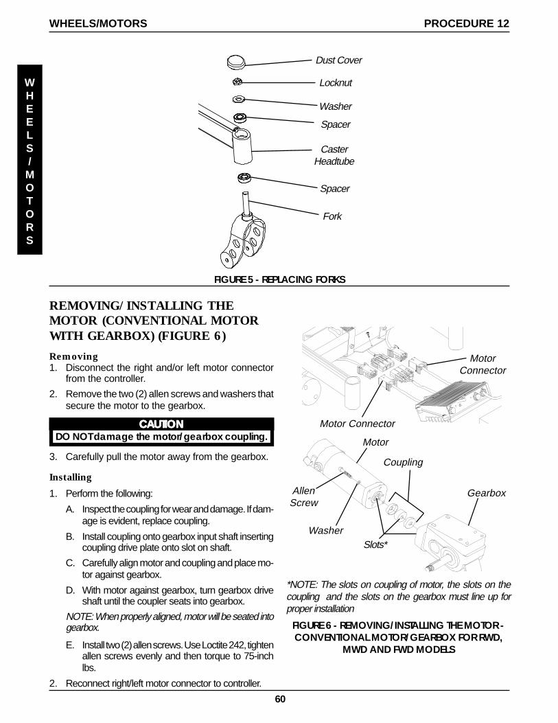
60
FIGURE 5 - REPLACING FORKS
Dust Cover
Locknut
Washer
Spacer
CasterHeadtube
Spacer
Fork
Installing
1. Perform the following:
A. Inspect the coupling for wear and damage. If dam-age is evident, replace coupling.
B. Install coupling onto gearbox input shaft insertingcoupling drive plate onto slot on shaft.
C. Carefully align motor and coupling and place mo-tor against gearbox.
D. With motor against gearbox, turn gearbox driveshaft until the coupler seats into gearbox.
NOTE: When properly aligned, motor will be seated intogearbox.
E. Install two (2) allen screws. Use Loctite 242, tightenallen screws evenly and then torque to 75-inchlbs.
2. Reconnect right/left motor connector to controller.
REMOVING/INSTALLING THEMOTOR (CONVENTIONAL MOTORWITH GEARBOX) (FIGURE 6)
Removing1. Disconnect the right and/or left motor connector
from the controller.
2. Remove the two (2) allen screws and washers thatsecure the motor to the gearbox.
CCCCCAAAAAUTIONUTIONUTIONUTIONUTIONDO NOT damage the motor/gearbox coupling.
3. Carefully pull the motor away from the gearbox.
FIGURE 6 - REMOVING/INSTALLING THE MOTOR -CONVENTIONAL MOTOR/GEARBOX FOR RWD,
MWD AND FWD MODELS
Slots*
*NOTE: The slots on coupling of motor, the slots on thecoupling and the slots on the gearbox must line up forproper installation
Gearbox
Motor
AllenScrew
Washer
Coupling
Motor Connector
MotorConnector
PROCEDURE 12WHEELS/MOTORS
WHEELS/MOTORS
61
3. Secure motor to the suspension arm with existingfour (4) mounting screws. Torque to 13 foot/pounds.
4. Slide the motor lock lever along brake release shaftuntil the end is flush with the bushing guide.
5. Slide alignment pin, located inside of bushingguide, into the end of the motor lock lever andsecure in place with existing mounting screw andwasher. Securely tighten.
6. Secure motor lock lever in place on the brake re-lease shaft with existing mounting screw.
7. Install the drive wheel from the wheelchair. Referto REMOVING/INSTALLING DRIVE WHEELS inthis procedure of the manual.
8. If necessary, install the 22nf battery box tray. Re-fer to REMOVING/INSTALLING 22NF BATTERYBOX TRAY in PROCEDURE 16 of this manual.
9. Plug the wiring harness connector into the motor.
10. Secure the wiring harness connector to the motorwith the existing two (2) mounting screws.
11. Remove the battery box(es). Refer to INSTALL-ING/REMOVING GROUP 24 BATTERY BOXESor INSTALLING/REMOVING 22NF BATTERYBOXES in PROCEDURE 9 of this manual.
REMOVING/INSTALLING THEMOTOR (GEARLESS/BRUSHLESSMOTOR) (FIGURE 7)Removing
1. Remove the battery box(es). Refer to INSTALLING/REMOVING GROUP 24 BATTERY BOXES or IN-STALLING/REMOVING GROUP 22 BATTERYBOXES in PROCEDURE 9 of this manual.
2. Unthread the mounting screws that secure the wiringharness connector to the motor.
3. Unplug the wiring harness connector from the motor.
4. If necessary, remove the group 22 battery box tray.Refer to REMOVING/INSTALLING 22NF BATTERYBOX TRAY in PROCEDURE 16 of this manual.
5. Remove the drive wheel from the wheelchair. Re-fer to REMOVING/INSTALLING DRIVE WHEELSin this procedure of the manual.
6. Note the mounting position of the motor on thesuspension arm before removing the motor.
7. Loosen adjustment screw that secures the motorlock lever in place on the brake release shaft.
NOTE: Alignment pin is located inside of bushing guideon the suspension arm.
8. Remove the mounting screw and washer that se-cure the alignment pin in place.
9. Slide the alignment pin back out of the end of themotor lock lever.
10. Remove the four (4) mounting screws and wash-ers that secure the motor to the suspension arm.
11. Remove motor with motor lock lever from suspen-sion arm.
12. If replacing motor, remove the motor lock leverfrom the brake release shaft of the existing motor.
Installing
NOTE: Do not tighten adjustment screw of motor lock le-ver until motor is secured in place on the suspension arm.
1. If necessary, install motor lock lever onto new brakerelease shaft of motor.
2. Position the new/existing motor with motor locklever onto the suspension arm in the mountingposition noted from STEP 4 of REMOVING THEGEARLESS/BRUSHLESS MOTOR in this proce-dure of the manual.
PROCEDURE 12WHEELS/MOTORS
WHEELS/MOTORS
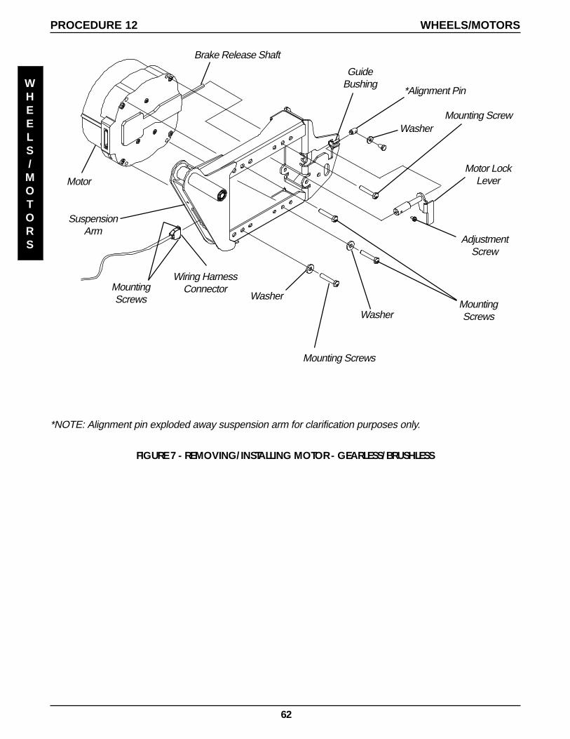
62
Mounting ScrewWasher
MountingScrews
Mounting Screws
Washer
Motor
SuspensionArm
Motor LockLever
AdjustmentScrew
Washer
*Alignment Pin
*NOTE: Alignment pin exploded away suspension arm for clarification purposes only.
Brake Release Shaft
GuideBushing
PROCEDURE 12 WHEELS/MOTORS
WHEELS/MOTORS
MountingScrews
Wiring HarnessConnector
FIGURE 7 - REMOVING/INSTALLING MOTOR - GEARLESS/BRUSHLESS
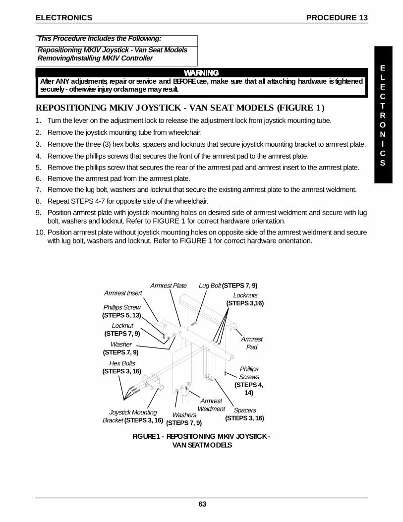
63
ELECTRONICS
PROCEDURE 13ELECTRONICS
REPOSITIONING MKIV JOYSTICK - VAN SEAT MODELS (FIGURE 1)1. Turn the lever on the adjustment lock to release the adjustment lock from joystick mounting tube.
2. Remove the joystick mounting tube from wheelchair.
3. Remove the three (3) hex bolts, spacers and locknuts that secure joystick mounting bracket to armrest plate.
4. Remove the phillips screws that secures the front of the armrest pad to the armrest plate.
5. Remove the phillips screw that secures the rear of the armrest pad and armrest insert to the armrest plate.
6. Remove the armrest pad from the armrest plate.
7. Remove the lug bolt, washers and locknut that secure the existing armrest plate to the armrest weldment.
8. Repeat STEPS 4-7 for opposite side of the wheelchair.
9. Position armrest plate with joystick mounting holes on desired side of armrest weldment and secure with lugbolt, washers and locknut. Refer to FIGURE 1 for correct hardware orientation.
10. Position armrest plate without joystick mounting holes on opposite side of the armrest weldment and securewith lug bolt, washers and locknut. Refer to FIGURE 1 for correct hardware orientation.
This Procedure Includes the Following:
Repositioning MKIV Joystick - Van Seat ModelsRemoving/Installing MKIV Controller
WWWWWARNINGARNINGARNINGARNINGARNINGAfter ANY adjustments, repair or service and BEFORE use, make sure that all attaching hardware is tightenedsecurely - otherwise injury or damage may result.
FIGURE 1 - REPOSITIONING MKIV JOYSTICK -VAN SEAT MODELS
Locknuts(STEPS 3,16)
PhillipsScrews
(STEPS 4,14)
Lug Bolt (STEPS 7, 9)
Joystick MountingBracket (STEPS 3, 16)
Hex Bolts(STEPS 3, 16)
Spacers(STEPS 3, 16)
Armrest Insert
Phillips Screw(STEPS 5, 13)
ArmrestPad
Armrest Plate
Washer(STEPS 7, 9)
Locknut(STEPS 7, 9)
Washers(STEPS 7, 9)
ArmrestWeldment
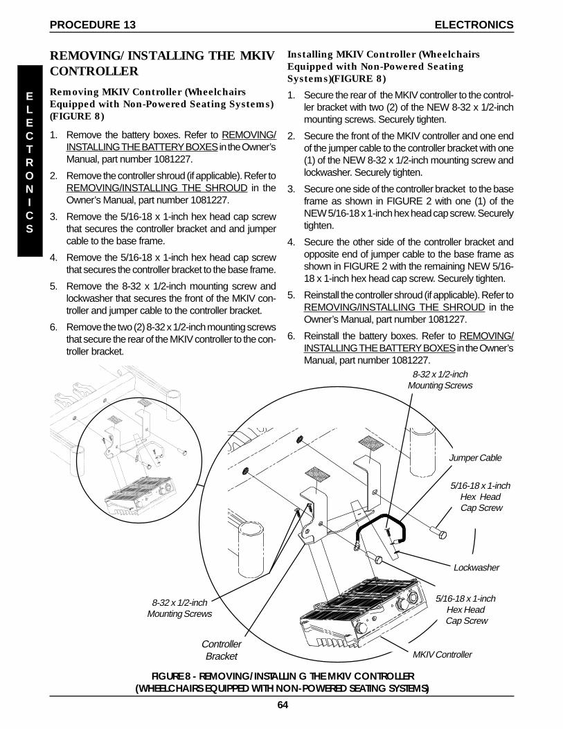
64
Installing MKIV Controller (WheelchairsEquipped with Non-Powered SeatingSystems)(FIGURE 8)
1. Secure the rear of the MKIV controller to the control-ler bracket with two (2) of the NEW 8-32 x 1/2-inchmounting screws. Securely tighten.
2. Secure the front of the MKIV controller and one endof the jumper cable to the controller bracket with one(1) of the NEW 8-32 x 1/2-inch mounting screw andlockwasher. Securely tighten.
3. Secure one side of the controller bracket to the baseframe as shown in FIGURE 2 with one (1) of theNEW 5/16-18 x 1-inch hex head cap screw. Securelytighten.
4. Secure the other side of the controller bracket andopposite end of jumper cable to the base frame asshown in FIGURE 2 with the remaining NEW 5/16-18 x 1-inch hex head cap screw. Securely tighten.
5. Reinstall the controller shroud (if applicable). Refer toREMOVING/INSTALLING THE SHROUD in theOwner’s Manual, part number 1081227.
6. Reinstall the battery boxes. Refer to REMOVING/INSTALLING THE BATTERY BOXES in the Owner’sManual, part number 1081227.
FIGURE 8 - REMOVING/INSTALLIN G THE MKIV CONTROLLER(WHEELCHAIRS EQUIPPED WITH NON-POWERED SEATING SYSTEMS)
8-32 x 1/2-inchMounting Screws
8-32 x 1/2-inchMounting Screws
ControllerBracket
5/16-18 x 1-inchHex Head Cap Screw
Jumper Cable
Lockwasher
5/16-18 x 1-inchHex Head
Cap Screw
MKIV Controller
REMOVING/INSTALLING THE MKIVCONTROLLER
Removing MKIV Controller (WheelchairsEquipped with Non-Powered Seating Systems)(FIGURE 8)
1. Remove the battery boxes. Refer to REMOVING/INSTALLING THE BATTERY BOXES in the Owner’sManual, part number 1081227.
2. Remove the controller shroud (if applicable). Refer toREMOVING/INSTALLING THE SHROUD in theOwner’s Manual, part number 1081227.
3. Remove the 5/16-18 x 1-inch hex head cap screwthat secures the controller bracket and and jumpercable to the base frame.
4. Remove the 5/16-18 x 1-inch hex head cap screwthat secures the controller bracket to the base frame.
5. Remove the 8-32 x 1/2-inch mounting screw andlockwasher that secures the front of the MKIV con-troller and jumper cable to the controller bracket.
6. Remove the two (2) 8-32 x 1/2-inch mounting screwsthat secure the rear of the MKIV controller to the con-troller bracket.
ELECTRONICS
PROCEDURE 13 ELECTRONICS
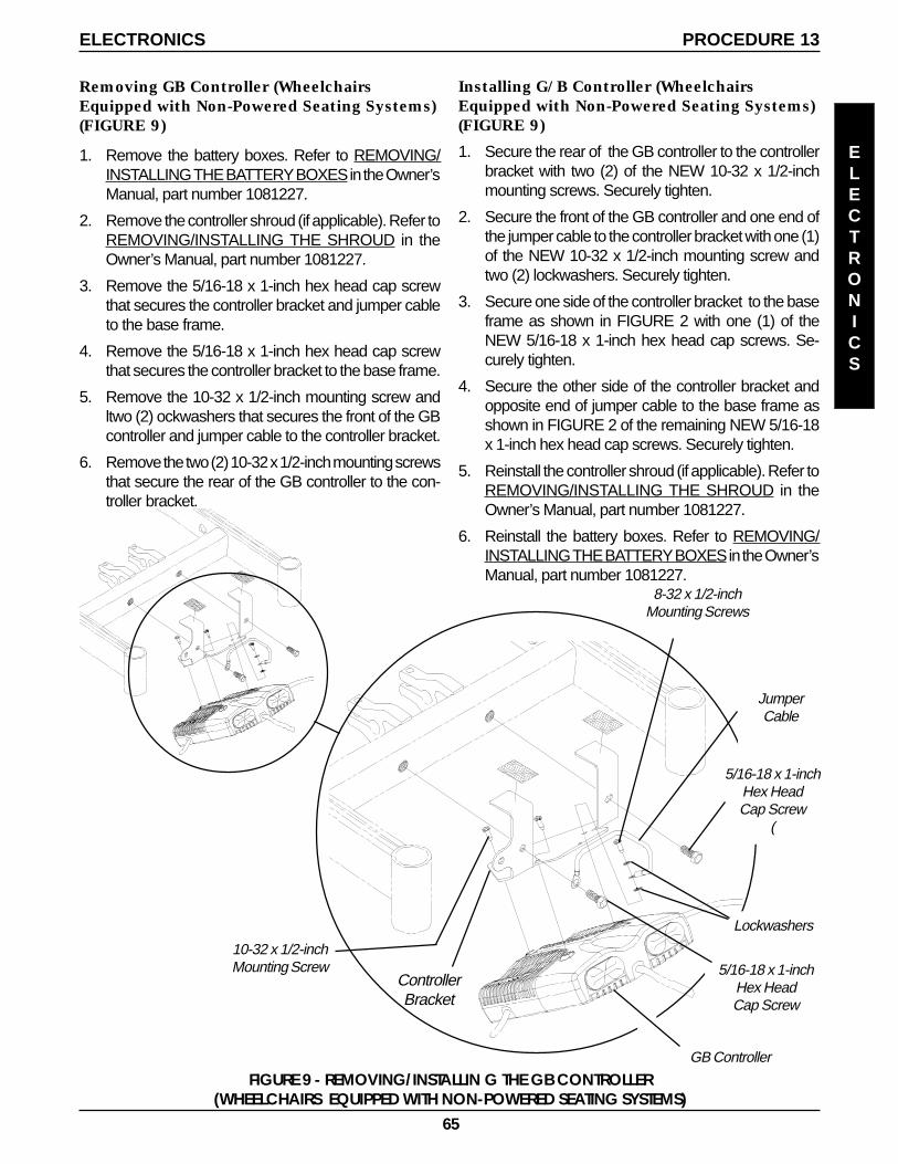
65
FIGURE 9 - REMOVING/INSTALLIN G THE GB CONTROLLER(WHEELCHAIRS EQUIPPED WITH NON-POWERED SEATING SYSTEMS)
10-32 x 1/2-inchMounting Screw
8-32 x 1/2-inchMounting Screws
JumperCable
Installing G/B Controller (WheelchairsEquipped with Non-Powered Seating Systems)(FIGURE 9)
1. Secure the rear of the GB controller to the controllerbracket with two (2) of the NEW 10-32 x 1/2-inchmounting screws. Securely tighten.
2. Secure the front of the GB controller and one end ofthe jumper cable to the controller bracket with one (1)of the NEW 10-32 x 1/2-inch mounting screw andtwo (2) lockwashers. Securely tighten.
3. Secure one side of the controller bracket to the baseframe as shown in FIGURE 2 with one (1) of theNEW 5/16-18 x 1-inch hex head cap screws. Se-curely tighten.
4. Secure the other side of the controller bracket andopposite end of jumper cable to the base frame asshown in FIGURE 2 of the remaining NEW 5/16-18x 1-inch hex head cap screws. Securely tighten.
5. Reinstall the controller shroud (if applicable). Refer toREMOVING/INSTALLING THE SHROUD in theOwner’s Manual, part number 1081227.
6. Reinstall the battery boxes. Refer to REMOVING/INSTALLING THE BATTERY BOXES in the Owner’sManual, part number 1081227.
ControllerBracket
GB Controller
5/16-18 x 1-inchHex HeadCap Screw
(
Removing GB Controller (WheelchairsEquipped with Non-Powered Seating Systems)(FIGURE 9)
1. Remove the battery boxes. Refer to REMOVING/INSTALLING THE BATTERY BOXES in the Owner’sManual, part number 1081227.
2. Remove the controller shroud (if applicable). Refer toREMOVING/INSTALLING THE SHROUD in theOwner’s Manual, part number 1081227.
3. Remove the 5/16-18 x 1-inch hex head cap screwthat secures the controller bracket and jumper cableto the base frame.
4. Remove the 5/16-18 x 1-inch hex head cap screwthat secures the controller bracket to the base frame.
5. Remove the 10-32 x 1/2-inch mounting screw andltwo (2) ockwashers that secures the front of the GBcontroller and jumper cable to the controller bracket.
6. Remove the two (2) 10-32 x 1/2-inch mounting screwsthat secure the rear of the GB controller to the con-troller bracket.
Lockwashers
5/16-18 x 1-inchHex HeadCap Screw
PROCEDURE 13ELECTRONICS
ELECTRONICS
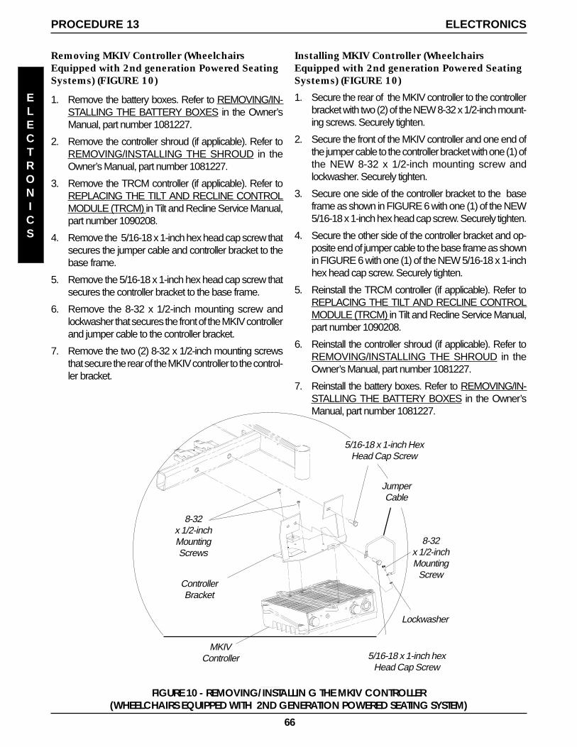
66
8-32x 1/2-inchMountingScrews
ControllerBracket
Lockwasher
Installing MKIV Controller (WheelchairsEquipped with 2nd generation Powered SeatingSystems) (FIGURE 10)
1. Secure the rear of the MKIV controller to the controllerbracket with two (2) of the NEW 8-32 x 1/2-inch mount-ing screws. Securely tighten.
2. Secure the front of the MKIV controller and one end ofthe jumper cable to the controller bracket with one (1) ofthe NEW 8-32 x 1/2-inch mounting screw andlockwasher. Securely tighten.
3. Secure one side of the controller bracket to the baseframe as shown in FIGURE 6 with one (1) of the NEW5/16-18 x 1-inch hex head cap screw. Securely tighten.
4. Secure the other side of the controller bracket and op-posite end of jumper cable to the base frame as shownin FIGURE 6 with one (1) of the NEW 5/16-18 x 1-inchhex head cap screw. Securely tighten.
5. Reinstall the TRCM controller (if applicable). Refer toREPLACING THE TILT AND RECLINE CONTROLMODULE (TRCM) in Tilt and Recline Service Manual,part number 1090208.
6. Reinstall the controller shroud (if applicable). Refer toREMOVING/INSTALLING THE SHROUD in theOwner’s Manual, part number 1081227.
7. Reinstall the battery boxes. Refer to REMOVING/IN-STALLING THE BATTERY BOXES in the Owner’sManual, part number 1081227.
8-32x 1/2-inchMounting
Screw
Removing MKIV Controller (WheelchairsEquipped with 2nd generation Powered SeatingSystems) (FIGURE 10)
1. Remove the battery boxes. Refer to REMOVING/IN-STALLING THE BATTERY BOXES in the Owner’sManual, part number 1081227.
2. Remove the controller shroud (if applicable). Refer toREMOVING/INSTALLING THE SHROUD in theOwner’s Manual, part number 1081227.
3. Remove the TRCM controller (if applicable). Refer toREPLACING THE TILT AND RECLINE CONTROLMODULE (TRCM) in Tilt and Recline Service Manual,part number 1090208.
4. Remove the 5/16-18 x 1-inch hex head cap screw thatsecures the jumper cable and controller bracket to thebase frame.
5. Remove the 5/16-18 x 1-inch hex head cap screw thatsecures the controller bracket to the base frame.
6. Remove the 8-32 x 1/2-inch mounting screw andlockwasher that secures the front of the MKIV controllerand jumper cable to the controller bracket.
7. Remove the two (2) 8-32 x 1/2-inch mounting screwsthat secure the rear of the MKIV controller to the control-ler bracket.
5/16-18 x 1-inch HexHead Cap Screw
JumperCable
MKIVController
FIGURE 10 - REMOVING/INSTALLIN G THE MKIV CONTROLLER(WHEELCHAIRS EQUIPPED WITH 2ND GENERATION POWERED SEATING SYSTEM)
5/16-18 x 1-inch hexHead Cap Screw
ELECTRONICS
PROCEDURE 13 ELECTRONICS
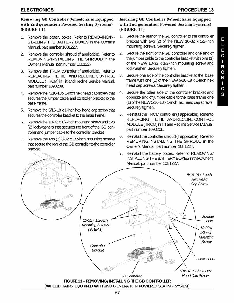
67
10-32 x 1/2-inchMounting Screws
(STEP 1)
JumperCable
5/16-18 x 1-inch HexHead Cap Screw
ControllerBracket
10-32 x1/2-inchMounting Screw
Lockwashers
5/16-18 x 1-inchHex HeadCap Screw
Installing GB Controller (Wheelchairs Equippedwith 2nd generation Powered Seating Systems)(FIGURE 11)
1. Secure the rear of the GB controller to the controllerbracket with two (2) of the NEW 10-32 x 1/2-inchmounting screws. Securely tighten.
2. Secure the front of the GB controller and one end ofthe jumper cable to the controller bracket with one (1)of the NEW 10-32 x 1/2-inch mounting screw andlockwasher. Securely tighten.
3. Secure one side of the controller bracket to the baseframe with one (1) of the NEW 5/16-18 x 1-inch hexhead cap screws. Securely tighten.
4. Secure the other side of the controller bracket andopposite end of jumper cable to the base frame one(1) of the NEW 5/16-18 x 1-inch hex head cap screws.Securely tighten.
5. Reinstall the TRCM controller (if applicable). Refer toREPLACING THE TILT AND RECLINE CONTROLMODULE (TRCM) in Tilt and Recline Service Manual,part number 1090208.
6. Reinstall the controller shroud (if applicable). Refer toREMOVING/INSTALLING THE SHROUD in theOwner’s Manual, part number 1081227.
7. Reinstall the battery boxes. Refer to REMOVING/INSTALLING THE BATTERY BOXES in the Owner’sManual, part number 1081227.
Removing GB Controller (Wheelchairs Equippedwith 2nd generation Powered Seating Systems)(FIGURE 11)
1. Remove the battery boxes. Refer to REMOVING/IN-STALLING THE BATTERY BOXES in the Owner’sManual, part number 1081227.
2. Remove the controller shroud (if applicable). Refer toREMOVING/INSTALLING THE SHROUD in theOwner’s Manual, part number 1081227.
3. Remove the TRCM controller (if applicable). Refer toREPLACING THE TILT AND RECLINE CONTROLMODULE (TRCM) in Tilt and Recline Service Manual,part number 1090208.
4. Remove the 5/16-18 x 1-inch hex head cap screw thatsecures the jumper cable and controller bracket to thebase frame.
5. Remove the 5/16-18 x 1-inch hex head cap screw thatsecures the controller bracket to the base frame.
6. Remove the 10-32 x 1/2-inch mounting screw and two(2) lockwashers that secures the front of the GB con-troller and jumper cable to the controller bracket.
7. Remove the two (2) 8-32 x 1/2-inch mounting screwsthat secure the rear of the GB controller to the controllerbracket.
FIGURE 11 - REMOVING/INSTALLING THE GB CONTROLLER(WHEELCHAIRS EQUIPPED WITH 2ND GENERATION POWERED SEATING SYSTEM)
GB Controller
PROCEDURE 13ELECTRONICS
ELECTRONICS
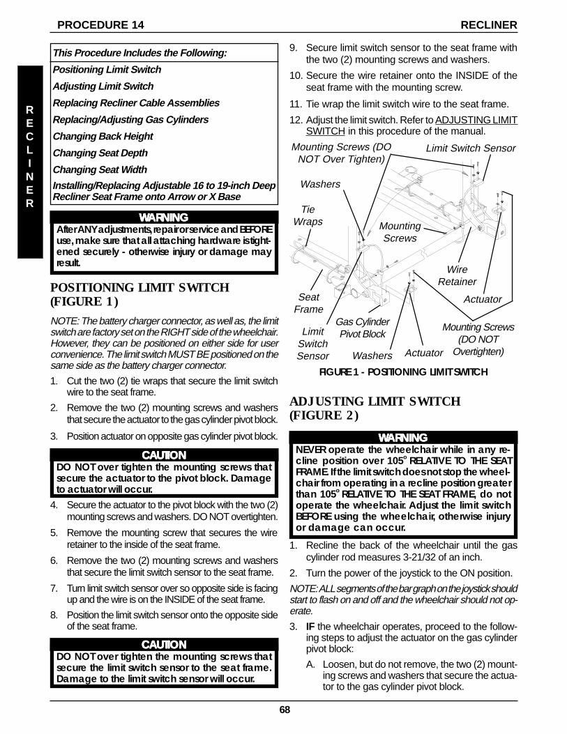
68
MountingScrews
Mounting Screws(DO NOT
Overtighten)
Actuator
TieWraps
WireRetainer
LimitSwitchSensor
SeatFrame
Mounting Screws (DONOT Over Tighten)
Washers
Limit Switch Sensor
FIGURE 1 - POSITIONING LIMIT SWITCH
Gas CylinderPivot Block
ActuatorWashers
POSITIONING LIMIT SWITCH(FIGURE 1)NOTE: The battery charger connector, as well as, the limitswitch are factory set on the RIGHT side of the wheelchair.However, they can be positioned on either side for userconvenience. The limit switch MUST BE positioned on thesame side as the battery charger connector.
1. Cut the two (2) tie wraps that secure the limit switchwire to the seat frame.
2. Remove the two (2) mounting screws and washersthat secure the actuator to the gas cylinder pivot block.
3. Position actuator on opposite gas cylinder pivot block.
CCCCCAAAAAUTIONUTIONUTIONUTIONUTIONDO NOT over tighten the mounting screws thatsecure the actuator to the pivot block. Damageto actuator will occur.
4. Secure the actuator to the pivot block with the two (2)mounting screws and washers. DO NOT overtighten.
5. Remove the mounting screw that secures the wireretainer to the inside of the seat frame.
6. Remove the two (2) mounting screws and washersthat secure the limit switch sensor to the seat frame.
7. Turn limit switch sensor over so opposite side is facingup and the wire is on the INSIDE of the seat frame.
8. Position the limit switch sensor onto the opposite sideof the seat frame.
CCCCCAAAAAUTIONUTIONUTIONUTIONUTIONDO NOT over tighten the mounting screws thatsecure the limit switch sensor to the seat frame.Damage to the limit switch sensor will occur.
This Procedure Includes the Following:
Positioning Limit Switch
Adjusting Limit Switch
Replacing Recliner Cable Assemblies
Replacing/Adjusting Gas Cylinders
Changing Back Height
Changing Seat Depth
Changing Seat Width
Installing/Replacing Adjustable 16 to 19-inch DeepRecliner Seat Frame onto Arrow or X Base
WWWWWARNINGARNINGARNINGARNINGARNINGAfter ANY adjustments, repair or service and BEFOREuse, make sure that all attaching hardware is tight-ened securely - otherwise injury or damage mayresult.
PROCEDURE 14 RECLINER
9. Secure limit switch sensor to the seat frame withthe two (2) mounting screws and washers.
10. Secure the wire retainer onto the INSIDE of theseat frame with the mounting screw.
11. Tie wrap the limit switch wire to the seat frame.
12. Adjust the limit switch. Refer to ADJUSTING LIMITSWITCH in this procedure of the manual.
ADJUSTING LIMIT SWITCH(FIGURE 2)
WWWWWARNINGARNINGARNINGARNINGARNINGNEVER operate the wheelchair while in any re-cline position over 105o RELATIVE TO THE SEATFRAME. If the limit switch does not stop the wheel-chair from operating in a recline position greaterthan 105o RELATIVE TO THE SEAT FRAME, do notoperate the wheelchair. Adjust the limit switchBEFORE using the wheelchair, otherwise injuryor damage can occur.
1. Recline the back of the wheelchair until the gascylinder rod measures 3-21/32 of an inch.
2. Turn the power of the joystick to the ON position.
NOTE: ALL segments of the bar graph on the joystick shouldstart to flash on and off and the wheelchair should not op-erate.
3. IF the wheelchair operates, proceed to the follow-ing steps to adjust the actuator on the gas cylinderpivot block:
A. Loosen, but do not remove, the two (2) mount-ing screws and washers that secure the actua-tor to the gas cylinder pivot block.
RECLINER
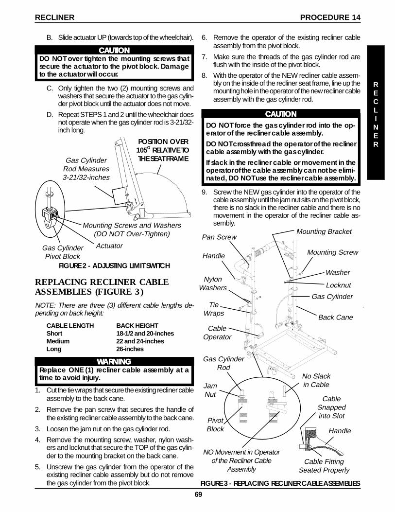
69
PROCEDURE 14RECLINER
FIGURE 2 - ADJUSTING LIMIT SWITCH
RECLINER
Mounting Screws and Washers(DO NOT Over-Tighten)
Actuator
Gas CylinderRod Measures3-21/32-inches
POSITION OVER105O RELATIVE TOTHE SEAT FRAME
Gas CylinderPivot Block
6. Remove the operator of the existing recliner cableassembly from the pivot block.
7. Make sure the threads of the gas cylinder rod areflush with the inside of the pivot block.
8. With the operator of the NEW recliner cable assem-bly on the inside of the recliner seat frame, line up themounting hole in the operator of the new recliner cableassembly with the gas cylinder rod.
CCCCCAAAAAUTIONUTIONUTIONUTIONUTIONDO NOT force the gas cylinder rod into the op-erator of the recliner cable assembly.DO NOT cross thread the operator of the reclinercable assembly with the gas cylinder.If slack in the recliner cable or movement in theoperator of the cable assembly can not be elimi-nated, DO NOT use the recliner cable assembly.
9. Screw the NEW gas cylinder into the operator of thecable assembly until the jam nut sits on the pivot block,there is no slack in the recliner cable and there is nomovement in the operator of the recliner cable as-sembly.
B. Slide actuator UP (towards top of the wheelchair).
CCCCCAAAAAUTIONUTIONUTIONUTIONUTIONDO NOT over tighten the mounting screws thatsecure the actuator to the pivot block. Damageto the actuator will occur.
C. Only tighten the two (2) mounting screws andwashers that secure the actuator to the gas cylin-der pivot block until the actuator does not move.
D. Repeat STEPS 1 and 2 until the wheelchair doesnot operate when the gas cylinder rod is 3-21/32-inch long.
REPLACING RECLINER CABLEASSEMBLIES (FIGURE 3)NOTE: There are three (3) different cable lengths de-pending on back height:
CABLE LENGTH BACK HEIGHTShort 18-1/2 and 20-inchesMedium 22 and 24-inchesLong 26-inches
WWWWWARNINGARNINGARNINGARNINGARNINGReplace ONE (1) recliner cable assembly at atime to avoid injury.
1. Cut the tie wraps that secure the existing recliner cableassembly to the back cane.
2. Remove the pan screw that secures the handle ofthe existing recliner cable assembly to the back cane.
3. Loosen the jam nut on the gas cylinder rod.
4. Remove the mounting screw, washer, nylon wash-ers and locknut that secure the TOP of the gas cylin-der to the mounting bracket on the back cane.
5. Unscrew the gas cylinder from the operator of theexisting recliner cable assembly but do not removethe gas cylinder from the pivot block. FIGURE 3 - REPLACING RECLINER CABLE ASSEMBLIES
JamNut
Washer
Handle
NylonWashers
PivotBlock
Locknut
Back Cane
Gas Cylinder
Gas CylinderRod
Mounting Screw
Pan Screw
No Slackin Cable
NO Movement in Operatorof the Recliner Cable
AssemblyCable Fitting
Seated Properly
Handle
CableSnappedinto Slot
CableOperator
TieWraps
Mounting Bracket
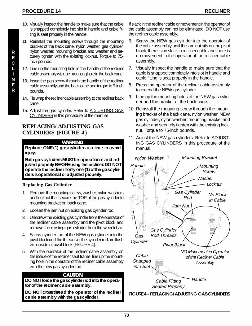
70
Gas CylinderRod
Jam Nut
GasCylinder
NO Movement in Operatorof the Recliner Cable
Assembly
Gas CylinderRod Threads
Handle
No Slackin Cable
FIGURE 4 - REPLACING/ADJUSTING GAS CYLINDERS
HandleCable FittingSeated Properly
Pivot Block
CableSnappedinto Slot
Nylon Washer
LocknutWasher
MountingScrew
Mounting Bracket
If slack in the recliner cable or movement in the operator ofthe cable assembly can not be eliminated, DO NOT usethe recliner cable assembly.
6. Screw the NEW gas cylinder into the operator ofthe cable assembly until the jam nut sits on the pivotblock, there is no slack in recliner cable and there isno movement in the operator of the recliner cableassembly.
7. Visually inspect the handle to make sure that thecable is snapped completely into slot in handle andcable fitting is seat properly in the handle.
8. Press the operator of the recliner cable assemblyto extend the NEW gas cylinder.
9. Line up the mounting holes of the NEW gas cylin-der and the bracket of the back cane.
10. Reinstall the mounting screw through the mount-ing bracket of the back cane, nylon washer, NEWgas cylinder, nylon washer, mounting bracket andwasher and securely tighten with the existing lock-nut. Torque to 75-inch pounds.
11. Adjust the NEW gas cylinders. Refer to ADJUST-ING GAS CYLINDERS in this procedure of themanual.
RECLINER
10. Visually inspect the handle to make sure that the cableis snapped completely into slot in handle and cable fit-ting is seat properly in the handle.
11. Reinstall the mounting screw through the mountingbracket of the back cane, nylon washer, gas cylinder,nylon washer, mounting bracket and washer and se-curely tighten with the existing locknut. Torque to 75-inch pounds.
12. Line up the mounting hole in the handle of the reclinercable assembly with the mounting hole in the back cane.
13. Insert the pan screw through the handle of the reclinercable assembly and the back cane and torque to 9-inchpounds.
14. Tie wrap the recliner cable assembly to the recliner backcane.
15. Adjust the gas cylinder. Refer to ADJUSTING GASCYLINDERS in this procedure of the manual.
REPLACING/ADJUSTING GASCYLINDERS (FIGURE 4)
WWWWWARNINGARNINGARNINGARNINGARNINGReplace ONE (1) gas cylinder at a time to avoidinjury.Both gas cylinders MUST be operational and ad-justed properly BEFORE using the recliner. DO NOToperate the recliner if only one (1) of the gas cylin-ders is operational or adjusted properly.
Replacing Gas Cylinder
1. Remove the mounting screw, washer, nylon washersand locknut that secure the TOP of the gas cylinder tomounting bracket on back cane.
2. Loosen the jam nut on existing gas cylinder rod.
3. Unscrew the existing gas cylinder from the operator ofthe recliner cable assembly and the pivot block andremove the existing gas cylinder from the wheelchair.
4. Screw cylinder rod of the NEW gas cylinder into thepivot block until the threads of the cylinder rod are flushwith inside of pivot block (FIGURE 4).
5. With the operator of the recliner cable assembly onthe inside of the recliner seat frame, line up the mount-ing hole in the operator of the recliner cable assemblywith the new gas cylinder rod.
CCCCCAAAAAUTIONUTIONUTIONUTIONUTIONDO NOT force the gas cylinder rod into the opera-tor of the recliner cable assembly.DO NOT cross thread the operator of the reclinercable assembly with the gas cylinder.
PROCEDURE 14 RECLINER
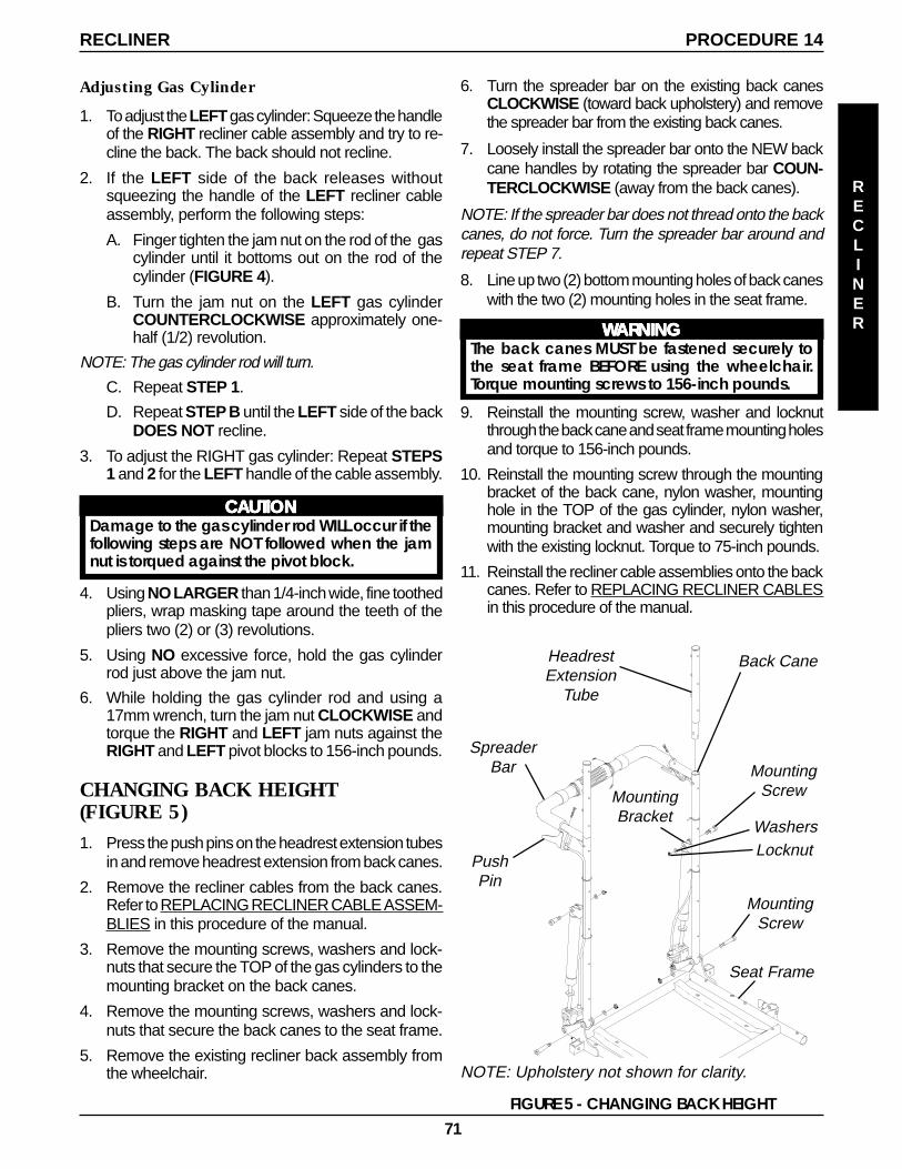
71
RECLINER
Adjusting Gas Cylinder
1. To adjust the LEFT gas cylinder: Squeeze the handleof the RIGHT recliner cable assembly and try to re-cline the back. The back should not recline.
2. If the LEFT side of the back releases withoutsqueezing the handle of the LEFT recliner cableassembly, perform the following steps:
A. Finger tighten the jam nut on the rod of the gascylinder until it bottoms out on the rod of thecylinder (FIGURE 4).
B. Turn the jam nut on the LEFT gas cylinderCOUNTERCLOCKWISE approximately one-half (1/2) revolution.
NOTE: The gas cylinder rod will turn.
C. Repeat STEP 1.
D. Repeat STEP B until the LEFT side of the backDOES NOT recline.
3. To adjust the RIGHT gas cylinder: Repeat STEPS1 and 2 for the LEFT handle of the cable assembly.
CCCCCAAAAAUTIONUTIONUTIONUTIONUTIONDamage to the gas cylinder rod WILL occur if thefollowing steps are NOT followed when the jamnut is torqued against the pivot block.
4. Using NO LARGER than 1/4-inch wide, fine toothedpliers, wrap masking tape around the teeth of thepliers two (2) or (3) revolutions.
5. Using NO excessive force, hold the gas cylinderrod just above the jam nut.
6. While holding the gas cylinder rod and using a17mm wrench, turn the jam nut CLOCKWISE andtorque the RIGHT and LEFT jam nuts against theRIGHT and LEFT pivot blocks to 156-inch pounds.
CHANGING BACK HEIGHT(FIGURE 5)1. Press the push pins on the headrest extension tubes
in and remove headrest extension from back canes.
2. Remove the recliner cables from the back canes.Refer to REPLACING RECLINER CABLE ASSEM-BLIES in this procedure of the manual.
3. Remove the mounting screws, washers and lock-nuts that secure the TOP of the gas cylinders to themounting bracket on the back canes.
4. Remove the mounting screws, washers and lock-nuts that secure the back canes to the seat frame.
5. Remove the existing recliner back assembly fromthe wheelchair.
FIGURE 5 - CHANGING BACK HEIGHT
MountingScrew
WashersLocknut
MountingScrew
Back Cane
SpreaderBar
NOTE: Upholstery not shown for clarity.
HeadrestExtension
Tube
PushPin
Seat Frame
MountingBracket
PROCEDURE 14RECLINER
6. Turn the spreader bar on the existing back canesCLOCKWISE (toward back upholstery) and removethe spreader bar from the existing back canes.
7. Loosely install the spreader bar onto the NEW backcane handles by rotating the spreader bar COUN-TERCLOCKWISE (away from the back canes).
NOTE: If the spreader bar does not thread onto the backcanes, do not force. Turn the spreader bar around andrepeat STEP 7.
8. Line up two (2) bottom mounting holes of back caneswith the two (2) mounting holes in the seat frame.
WWWWWARNINGARNINGARNINGARNINGARNINGThe back canes MUST be fastened securely tothe seat frame BEFORE using the wheelchair.Torque mounting screws to 156-inch pounds.
9. Reinstall the mounting screw, washer and locknutthrough the back cane and seat frame mounting holesand torque to 156-inch pounds.
10. Reinstall the mounting screw through the mountingbracket of the back cane, nylon washer, mountinghole in the TOP of the gas cylinder, nylon washer,mounting bracket and washer and securely tightenwith the existing locknut. Torque to 75-inch pounds.
11. Reinstall the recliner cable assemblies onto the backcanes. Refer to REPLACING RECLINER CABLESin this procedure of the manual.
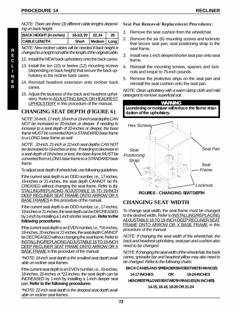
72
PROCEDURE 14 RECLINER
Hex Screws
Seat Pan
SeatFrame
FIGURE 6 - CHANGING SEAT DEPTH
Locknuts
SeatPositioning
Strap
CHANGING SEAT WIDTHTo change seat width, the seat frame must be changedto the desired width. Refer to INSTALLING/REPLACINGADJUSTABLE 16 TO 19-INCH DEEP RECLINER SEATFRAME ONTO ARROW OR X BASE FRAME in thisprocedure of the manual.
NOTE: If changing the seat width of the wheelchair, theback and headrest upholstery, seat pan and cushion alsoneed to be changed.
NOTE: If changing the seat width of the wheelchair, the backcanes, spreader bar and headrest pillow may also need tobe changed. Refer to the following charts:
BACK CANES AND SPREADER BAR SEAT WIDTH RANGES14-17-INCHES OR 18-24-INCHES
HEADREST PILLOWS SEAT WIDTH RANGES (IN INCHES)14-15, 16-18, 19-20 OR 21-24
RECLINER
NOTE: There are three (3) different cable lengths depend-ing on back height:BACK HEIGHT (in inches) 18-1/2, 20 22, 24 26
CABLE LENGTH Short Medium Long
NOTE: New recliner cables will be needed if back height ischanged to a height not within the length of the original cable.
12. Install the NEW back upholstery onto the back canes.
13. Install the ten (10) or twelve (12) mounting screws(depending on back height) that secure the back up-holstery to the recliner back canes.
14. Reinstall headrest extension onto recliner backcanes.
15. Adjust the tautness of the back and headrest uphol-stery. Refer to ADJUSTING BACK OR HEADRESTUPHOLSTERY in this procedure of the manual.
CHANGING SEAT DEPTH (FIGURE 6)NOTE: 16-inch, 17-inch, 18-inch or 19-inch seat depths CANNOT be increased to 20-inches or deeper. If needing toincrease to a seat depth of 20-inches or deeper, the baseframe MUST be converted from a STANDARD base frameto a LONG base frame as well.
NOTE: 20-inch, 21-inch or 22-inch seat depths CAN NOTbe decreased to 19-inches or less. If needing to decrease toa seat depth of 19-inches or less, the base frame MUST beconverted from a LONG base frame to a STANDARD baseframe.
To adjust seat depth of wheelchair, use following guidelines:
If the current seat depth is an ODD number, i.e., 17-inches,19-inches or 21-inches, the seat depth CANNOT be IN-CREASED without changing the seat frame. Refer to IN-STALLING/REPLACING ADJUSTABLE 16 TO 19-INCHDEEP RECLINER SEAT FRAME ONTO ARROW OR XBASE FRAMES in this procedure of the manual.
If the current seat depth is an ODD number, i.e., 17-inches,19-inches or 21-inches, the seat depth can be DECREASEDby 1-inch by installing a 1-inch shorter seat pan. Refer to thefollowing procedures:
If the current seat depth is an EVEN number, i.e., *16-inches,18-inches, 20-inches or 22-inches, the seat depth CANNOTbe DECREASED without changing the seat frame. Refer toINSTALLING/REPLACING ADJUSTABLE 16 TO 19-INCHDEEP RECLINER SEAT FRAME ONTO ARROW OR XBASE FRAME in this procedure of the manual.
*NOTE: 16-inch seat depth is the smallest seat depth avail-able on recliner seat frames.
If the current seat depth is an EVEN number, i.e., 16-inches,18-inches, 20-inches or *22-inches, the seat depth can beINCREASED by 1-inch by installing a 1-inch deeper seatpan. Refer to the following procedures:
*NOTE: 22-inch seat depth is the deepest seat depth avail-able on recliner seat frames.
Seat Pan Removal/Replacement Procedures:
1. Remove the seat cushion from the wheelchair.
2. Remove the six (6) mounting screws and locknutsthat secure seat pan, seat positioning strap to theseat frame.
3. Install new 1-inch deeper/shorter seat pan onto seatframe.
4. Reinstall the mounting screws, spacers and lock-nuts and torque to 75-inch pounds.
5. Remove the protective strips on the seat pan andreinstall the seat cushion onto the seat pan.
NOTE: Clean upholstery with a warm damp cloth and milddetergent to remove superficial soil.
WWWWWARNINGARNINGARNINGARNINGARNINGLaundering or moisture will reduce the flame retar-dation of the upholstery.
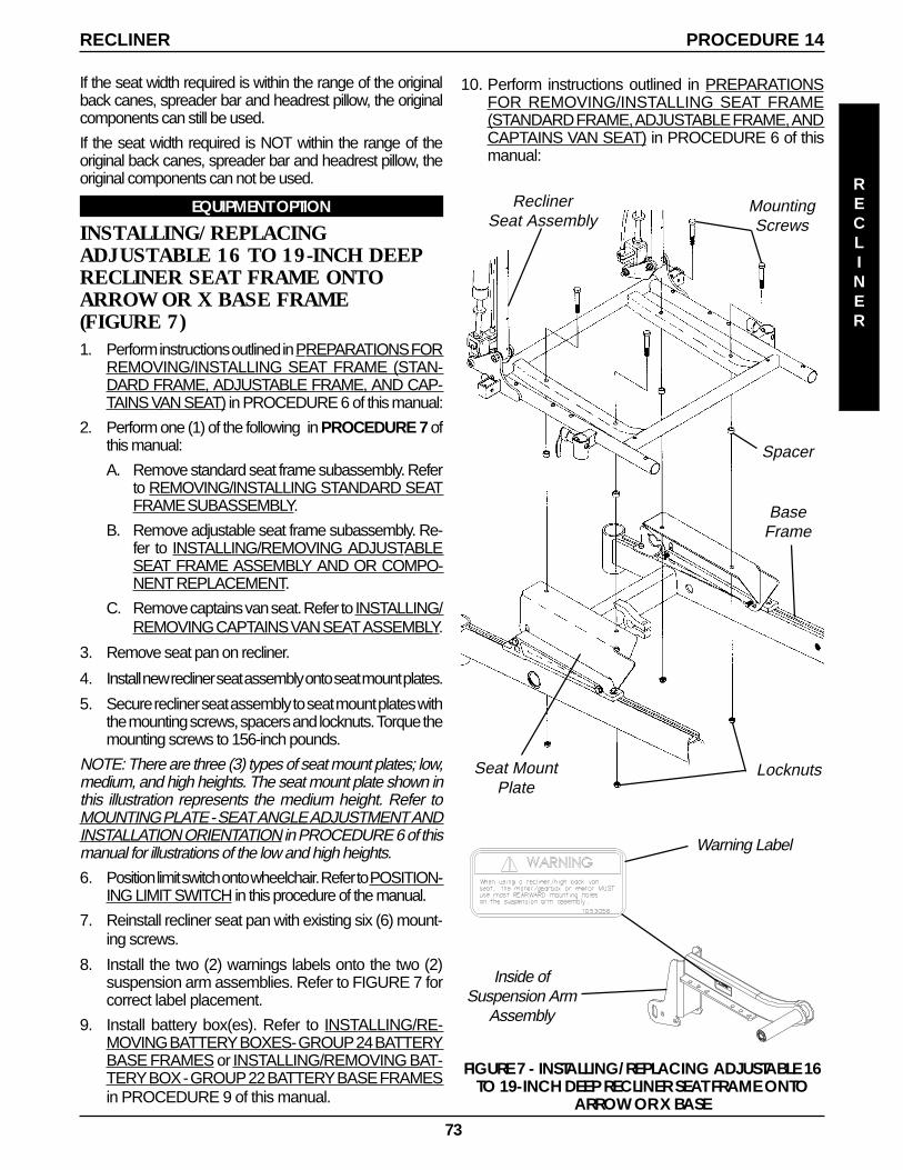
73
RECLINER
PROCEDURE 14RECLINER
FIGURE 7 - INSTALLING/REPLACING ADJUSTABLE 16TO 19-INCH DEEP RECLINER SEAT FRAME ONTO
ARROW OR X BASE
MountingScrews
BaseFrame
Spacer
ReclinerSeat Assembly
Seat MountPlate
Locknuts
If the seat width required is within the range of the originalback canes, spreader bar and headrest pillow, the originalcomponents can still be used.
If the seat width required is NOT within the range of theoriginal back canes, spreader bar and headrest pillow, theoriginal components can not be used.
EQUIPMENT OPTION
INSTALLING/REPLACINGADJUSTABLE 16 TO 19-INCH DEEPRECLINER SEAT FRAME ONTOARROW OR X BASE FRAME(FIGURE 7)1. Perform instructions outlined in PREPARATIONS FOR
REMOVING/INSTALLING SEAT FRAME (STAN-DARD FRAME, ADJUSTABLE FRAME, AND CAP-TAINS VAN SEAT) in PROCEDURE 6 of this manual:
2. Perform one (1) of the following in PROCEDURE 7 ofthis manual:
A. Remove standard seat frame subassembly. Referto REMOVING/INSTALLING STANDARD SEATFRAME SUBASSEMBLY.
B. Remove adjustable seat frame subassembly. Re-fer to INSTALLING/REMOVING ADJUSTABLESEAT FRAME ASSEMBLY AND OR COMPO-NENT REPLACEMENT.
C. Remove captains van seat. Refer to INSTALLING/REMOVING CAPTAINS VAN SEAT ASSEMBLY.
3. Remove seat pan on recliner.
4. Install new recliner seat assembly onto seat mount plates.
5. Secure recliner seat assembly to seat mount plates withthe mounting screws, spacers and locknuts. Torque themounting screws to 156-inch pounds.
NOTE: There are three (3) types of seat mount plates; low,medium, and high heights. The seat mount plate shown inthis illustration represents the medium height. Refer toMOUNTING PLATE - SEAT ANGLE ADJUSTMENT ANDINSTALLATION ORIENTATION in PROCEDURE 6 of thismanual for illustrations of the low and high heights.
6. Position limit switch onto wheelchair. Refer to POSITION-ING LIMIT SWITCH in this procedure of the manual.
7. Reinstall recliner seat pan with existing six (6) mount-ing screws.
8. Install the two (2) warnings labels onto the two (2)suspension arm assemblies. Refer to FIGURE 7 forcorrect label placement.
9. Install battery box(es). Refer to INSTALLING/RE-MOVING BATTERY BOXES- GROUP 24 BATTERYBASE FRAMES or INSTALLING/REMOVING BAT-TERY BOX - GROUP 22 BATTERY BASE FRAMESin PROCEDURE 9 of this manual.
10. Perform instructions outlined in PREPARATIONSFOR REMOVING/INSTALLING SEAT FRAME(STANDARD FRAME, ADJUSTABLE FRAME, ANDCAPTAINS VAN SEAT) in PROCEDURE 6 of thismanual:
Warning Label
Inside ofSuspension Arm
Assembly
74
RWD WHEELCHAIRSPROCEDURE 16
RWD
WHEELCHAIRS
This Procedure includes the following:Removing/Installing Group 24 Battery Box Sub-Frame
Removing/Installing Group 22 Battery Box Tray
Converting Group 22 Batteries to Group 24 Batteries
Shock Replacement
Shock Spring Replacement
Rubber Element Replacement
Converting Torque and X Rubber Elements to Shocks
Anti-Tipper Wheel Replacement
Removing/Installing Gearbox
Adjusting Weight Distribution
Repositioning Motor/ Gearbox Assembly
Repositioning Gear less/Brushless Motor
Replacing Suspension Arm for Wheelchairs with Motor/Gearbox assembly
Replacing Suspension Arm for Wheelchairs with Gearless/Brushless Motor
Removing/Installing the Anti-tip Assembly
Installing
1. Install the two (2) mounting screws and locknuts thatsecure the wiring harness w/bracket and the NEWsub-frame to the base frame. Use Loctite 242 andtorque mounting screws to 160-inch pounds.
2. Perform one (1) of the following:
A. WHEELCHAIRS EQUIPPED WITH VENTTRAY - Reinstall the four (4) mounting screwsthat secure the shocks, retainer bar, spacersand retainer clips to the base frame. UseLoctite 242 and torque mounting screws to160-inch pounds.
B. WHEELCHAIRS WITHOUT VENT TRAY -Reinstall the four (4) mounting screws that se-cure the shocks and spacers to the baseframe.
3. Reinstall the battery boxes. Refer to INSTALLING/REMOVING GROUP 24 BATTERY BOXES inPROCEDURE 9 of this manual. Use Loctite 242 andtorque mounting screws to 160-inch pounds.
WWWWWARNINGARNINGARNINGARNINGARNINGAfter ANY adjustments, repair or service and BE-FORE use, make sure that all attaching hardwareis tightened securely - otherwise injury or dam-age may result.
REMOVING/INSTALLING GROUP 24BATTERY BOX SUB-FRAME (FIGURE 1)
Removing
1. Remove the battery boxes. Refer to INSTALLING/RE-MOVING GROUP 24 BATTERY BOXES in PRO-CEDURE 9 of this manual.
2. Remove the two (2) mounting screws and locknutsthat secure the wiring harness w/bracket and the sub-frame to the base frame.
3. Perform one (1) of the following:A. WHEELCHAIRS EQUIPPED WITH VENT
TRAY - Remove the four (4) mounting screwsthat secure the shocks, retainer bar, spacers andretainer clips to the base frame.
B. WHEELCHAIRS WITHOUT VENT TRAY -Remove the four (4) mounting screws that se-cure the shocks and spacers to the baseframe.
4. Remove the existing sub-frame assembly.
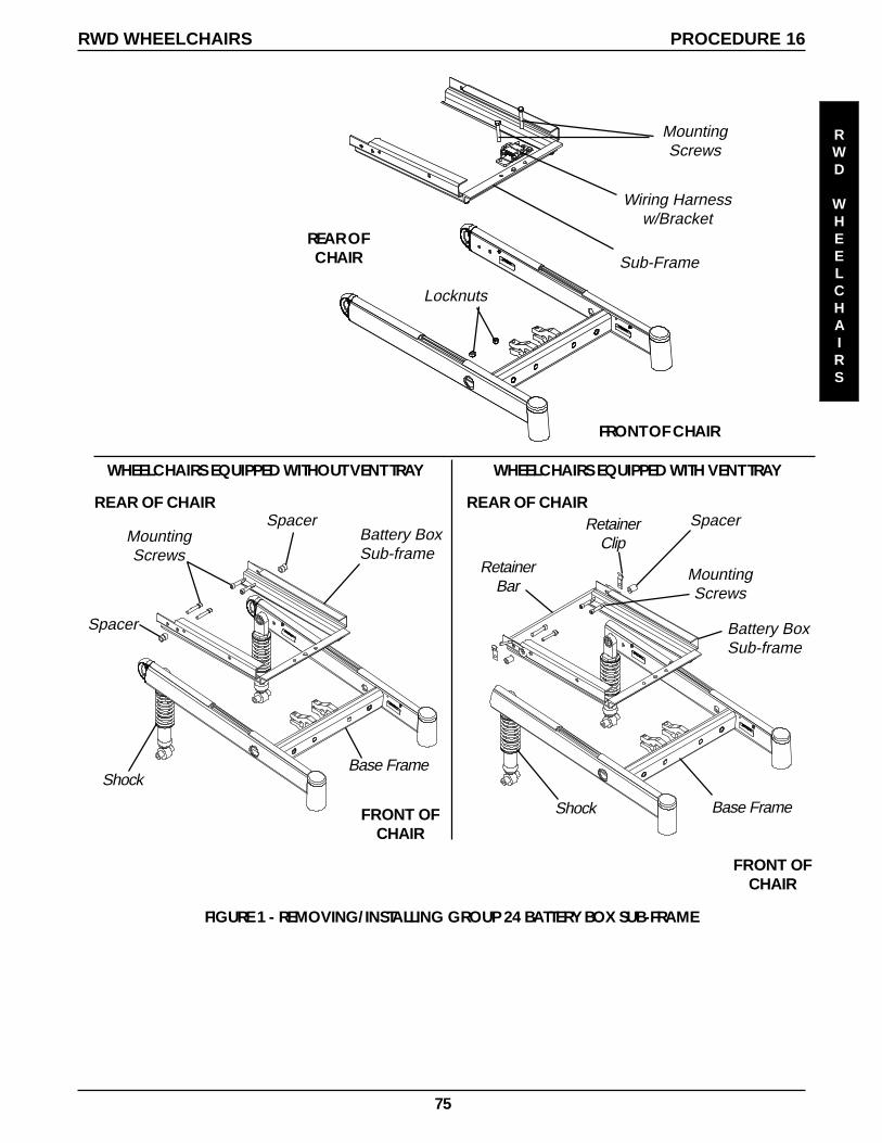
75
FIGURE 1 - REMOVING/INSTALLING GROUP 24 BATTERY BOX SUB-FRAME
SpacerBattery BoxSub-frame
MountingScrews
Wiring Harnessw/Bracket
Sub-Frame
Locknuts
REAR OFCHAIR
REAR OF CHAIR
FRONT OFCHAIR
MountingScrews
FRONT OF CHAIR
Shock
WHEELCHAIRS EQUIPPED WITHOUT VENT TRAY WHEELCHAIRS EQUIPPED WITH VENT TRAY
Spacer
Base Frame
MountingScrews
Battery BoxSub-frame
Base FrameShock
FRONT OFCHAIR
REAR OF CHAIR
RetainerBar
RetainerClip
Spacer
RWD WHEELCHAIRS PROCEDURE 16
RWD
WHEELCHAIRS
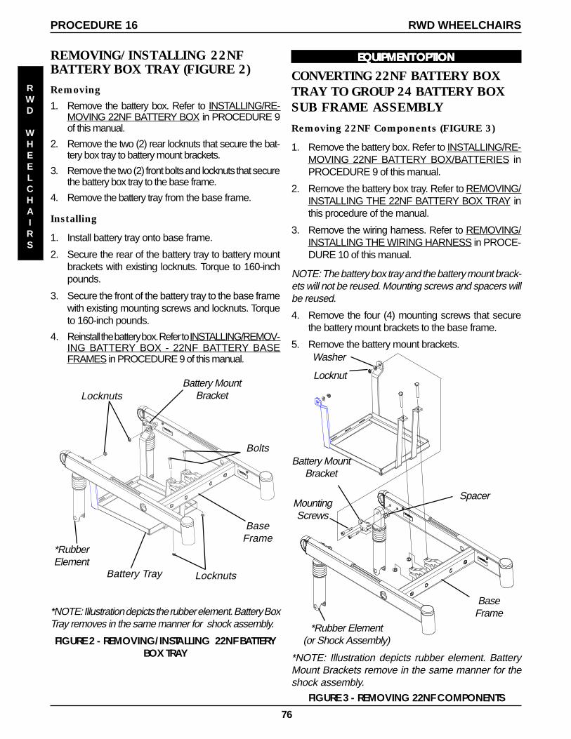
76
REMOVING/INSTALLING 22NFBATTERY BOX TRAY (FIGURE 2)
Removing
1. Remove the battery box. Refer to INSTALLING/RE-MOVING 22NF BATTERY BOX in PROCEDURE 9of this manual.
2. Remove the two (2) rear locknuts that secure the bat-tery box tray to battery mount brackets.
3. Remove the two (2) front bolts and locknuts that securethe battery box tray to the base frame.
4. Remove the battery tray from the base frame.
FIGURE 2 - REMOVING/INSTALLING 22NF BATTERYBOX TRAY
*NOTE: Illustration depicts the rubber element. Battery BoxTray removes in the same manner for shock assembly.
Installing
1. Install battery tray onto base frame.
2. Secure the rear of the battery tray to battery mountbrackets with existing locknuts. Torque to 160-inchpounds.
3. Secure the front of the battery tray to the base framewith existing mounting screws and locknuts. Torqueto 160-inch pounds.
4. Reinstall the battery box. Refer to INSTALLING/REMOV-ING BATTERY BOX - 22NF BATTERY BASEFRAMES in PROCEDURE 9 of this manual.
Battery Tray
Locknuts
Bolts
*RubberElement
BaseFrame
Battery MountBracket
Locknuts
EQUIPMENT OPTIONEQUIPMENT OPTIONEQUIPMENT OPTIONEQUIPMENT OPTIONEQUIPMENT OPTION
CONVERTING 22NF BATTERY BOXTRAY TO GROUP 24 BATTERY BOXSUB FRAME ASSEMBLY
Removing 22NF Components (FIGURE 3)
1. Remove the battery box. Refer to INSTALLING/RE-MOVING 22NF BATTERY BOX/BATTERIES inPROCEDURE 9 of this manual.
2. Remove the battery box tray. Refer to REMOVING/INSTALLING THE 22NF BATTERY BOX TRAY inthis procedure of the manual.
3. Remove the wiring harness. Refer to REMOVING/INSTALLING THE WIRING HARNESS in PROCE-DURE 10 of this manual.
NOTE: The battery box tray and the battery mount brack-ets will not be reused. Mounting screws and spacers willbe reused.
4. Remove the four (4) mounting screws that securethe battery mount brackets to the base frame.
5. Remove the battery mount brackets.
Spacer
Battery MountBracket
*Rubber Element(or Shock Assembly)
MountingScrews
BaseFrame
FIGURE 3 - REMOVING 22NF COMPONENTS
*NOTE: Illustration depicts rubber element. BatteryMount Brackets remove in the same manner for theshock assembly.
Locknut
Washer
RWD WHEELCHAIRSPROCEDURE 16
RWD
WHEELCHAIRS
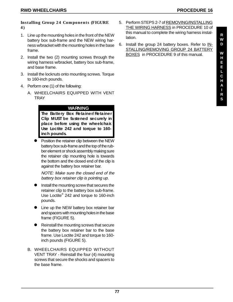
77
Installing Group 24 Components (FIGURE4)
1. Line up the mounting holes in the front of the NEWbattery box sub-frame and the NEW wiring har-ness w/bracket with the mounting holes in the baseframe.
2. Install the two (2) mounting screws through thewiring harness w/bracket, battery box sub-frame,and base frame.
3. Install the locknuts onto mounting screws. Torqueto 160-inch pounds.
4. Perform one (1) of the following:
A. WHEELCHAIRS EQUIPPED WITH VENTTRAY
WARNINGThe Battery Box Retainer/RetainerClip MUST be fastened securely inplace before using the wheelchair.Use Loctite 242 and torque to 160-inch pounds.
l Position the retainer clip between the NEWbattery box sub-frame and the top of the rub-ber element or shock assembly making surethe retainer clip mounting hole is towardsthe bottom and the closed end of the clip isagainst the battery box retainer bar.
NOTE: Make sure the closed end of thebattery box retainer clip is pointing up.
l Install the mounting screw that secures theretainer clip to the battery box sub-frame.Use Loctite® 242 and torque to 160-inchpounds.
l Line up the NEW battery box retainer barand spacers with mounting holes in the baseframe (FIGURE 5).
l Reinstall the mounting screws that securethe battery box retainer bar to the baseframe. Use Loctite 242 and torque to 160-inch pounds (FIGURE 5).
5. Perform STEPS 2-7 of REMOVING/INSTALLINGTHE WIRING HARNESS in PROCEDURE 10 ofthis manual to complete the wiring harness instal-lation.
6. Install the group 24 battery boxes. Refer to IN-STALLING/REMOVING GROUP 24 BATTERYBOXES in PROCEDURE 9 of this manual.
B. WHEELCHAIRS EQUIPPED WITHOUTVENT TRAY - Reinstall the four (4) mountingscrews that secure the shocks and spacers tothe base frame.
RWD WHEELCHAIRS PROCEDURE 16
RWD
WHEELCHAIRS
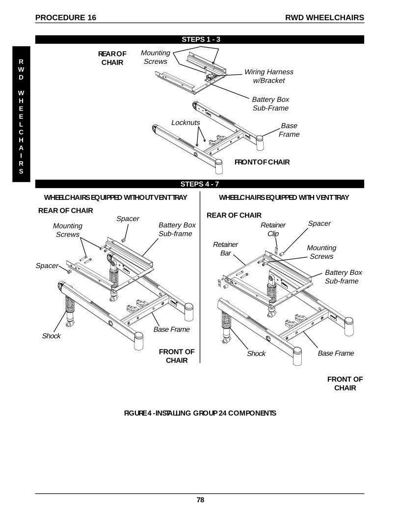
78
STEPS 1 - 3
STEPS 4 - 7
Wiring Harnessw/Bracket
MountingScrews
Battery BoxSub-Frame
BaseFrame
Locknuts
FIGURE 4 -INSTALLING GROUP 24 COMPONENTS
REAR OFCHAIR
FRONT OF CHAIR
SpacerBattery BoxSub-frame
REAR OF CHAIR
FRONT OFCHAIR
MountingScrews
Shock
WHEELCHAIRS EQUIPPED WITHOUT VENT TRAY
Spacer
Base Frame
WHEELCHAIRS EQUIPPED WITH VENT TRAY
MountingScrews
Battery BoxSub-frame
Base FrameShock
FRONT OFCHAIR
REAR OF CHAIR
RetainerBar
RetainerClip
Spacer
RWD WHEELCHAIRSPROCEDURE 16
RWD
WHEELCHAIRS
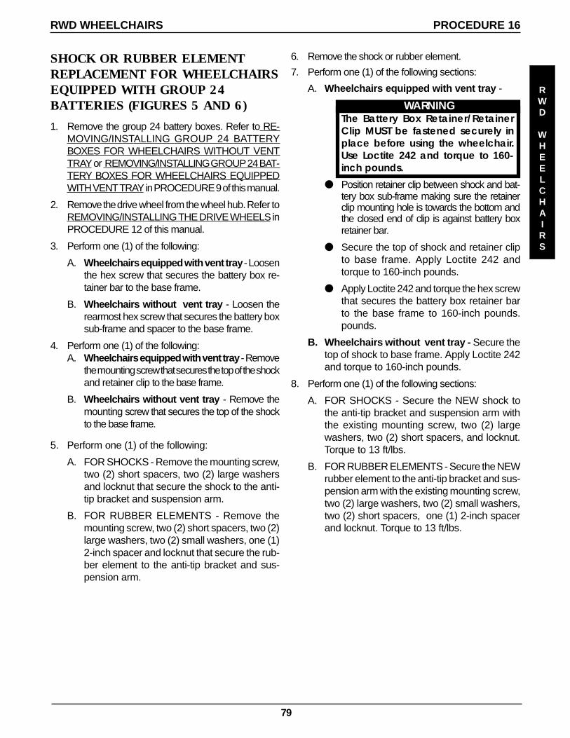
79
SHOCK OR RUBBER ELEMENTREPLACEMENT FOR WHEELCHAIRSEQUIPPED WITH GROUP 24BATTERIES (FIGURES 5 AND 6)
1. Remove the group 24 battery boxes. Refer to RE-MOVING/INSTALLING GROUP 24 BATTERYBOXES FOR WHEELCHAIRS WITHOUT VENTTRAY or REMOVING/INSTALLING GROUP 24 BAT-TERY BOXES FOR WHEELCHAIRS EQUIPPEDWITH VENT TRAY in PROCEDURE 9 of this manual.
2. Remove the drive wheel from the wheel hub. Refer toREMOVING/INSTALLING THE DRIVE WHEELS inPROCEDURE 12 of this manual.
3. Perform one (1) of the following:
A. Wheelchairs equipped with vent tray - Loosenthe hex screw that secures the battery box re-tainer bar to the base frame.
B. Wheelchairs without vent tray - Loosen therearmost hex screw that secures the battery boxsub-frame and spacer to the base frame.
4. Perform one (1) of the following:A. Wheelchairs equipped with vent tray - Remove
the mounting screw that secures the top of the shockand retainer clip to the base frame.
B. Wheelchairs without vent tray - Remove themounting screw that secures the top of the shockto the base frame.
5. Perform one (1) of the following:
A. FOR SHOCKS - Remove the mounting screw,two (2) short spacers, two (2) large washersand locknut that secure the shock to the anti-tip bracket and suspension arm.
B. FOR RUBBER ELEMENTS - Remove themounting screw, two (2) short spacers, two (2)large washers, two (2) small washers, one (1)2-inch spacer and locknut that secure the rub-ber element to the anti-tip bracket and sus-pension arm.
6. Remove the shock or rubber element.
7. Perform one (1) of the following sections:
A. Wheelchairs equipped with vent tray -
WARNINGThe Battery Box Retainer/RetainerClip MUST be fastened securely inplace before using the wheelchair.Use Loctite 242 and torque to 160-inch pounds.
Position retainer clip between shock and bat-tery box sub-frame making sure the retainerclip mounting hole is towards the bottom andthe closed end of clip is against battery boxretainer bar.
Secure the top of shock and retainer clipto base frame. Apply Loctite 242 andtorque to 160-inch pounds.
Apply Loctite 242 and torque the hex screwthat secures the battery box retainer barto the base frame to 160-inch pounds.pounds.
B. Wheelchairs without vent tray - Secure thetop of shock to base frame. Apply Loctite 242and torque to 160-inch pounds.
8. Perform one (1) of the following sections:
A. FOR SHOCKS - Secure the NEW shock tothe anti-tip bracket and suspension arm withthe existing mounting screw, two (2) largewashers, two (2) short spacers, and locknut.Torque to 13 ft/lbs.
B. FOR RUBBER ELEMENTS - Secure the NEWrubber element to the anti-tip bracket and sus-pension arm with the existing mounting screw,two (2) large washers, two (2) small washers,two (2) short spacers, one (1) 2-inch spacerand locknut. Torque to 13 ft/lbs.
RWD WHEELCHAIRS PROCEDURE 16
RWD
WHEELCHAIRS
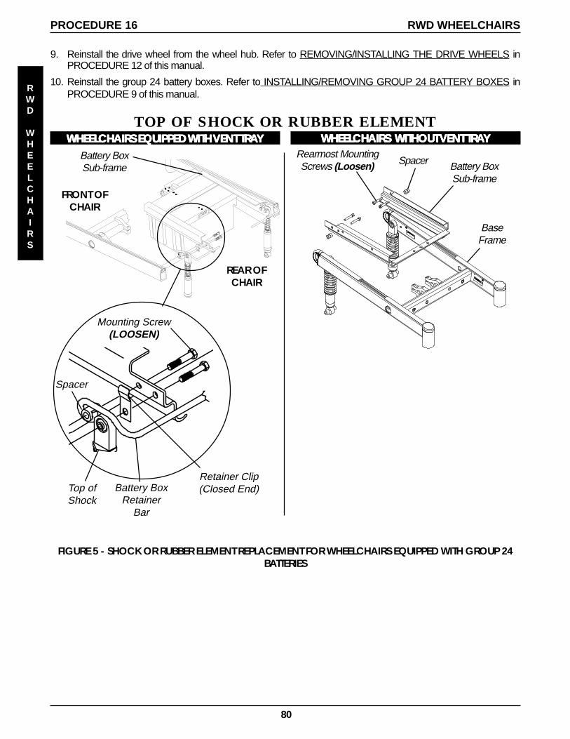
80
Battery BoxSub-frame
REAR OFCHAIR
FRONT OFCHAIR
Spacer
Mounting Screw(LOOSEN)
Retainer Clip(Closed End)
WHEELCHAIRS EQUIPPED WHEELCHAIRS EQUIPPED WHEELCHAIRS EQUIPPED WHEELCHAIRS EQUIPPED WHEELCHAIRS EQUIPPED WITH WITH WITH WITH WITH VENT VENT VENT VENT VENT TRATRATRATRATRAYYYYY
Top ofShock
Battery BoxRetainer
Bar
TOP OF SHOCK OR RUBBER ELEMENTWHEELCHAIRS WHEELCHAIRS WHEELCHAIRS WHEELCHAIRS WHEELCHAIRS WITHOUT WITHOUT WITHOUT WITHOUT WITHOUT VENT VENT VENT VENT VENT TRATRATRATRATRAYYYYY
Battery BoxSub-frame
BaseFrame
Rearmost MountingScrews (Loosen) Spacer
FIGURE 5 - SHOCK OR RUBBER ELEMENT REPLACEMENT FOR WHEELCHAIRS EQUIPPED WITH GROUP 24BATTERIES
9. Reinstall the drive wheel from the wheel hub. Refer to REMOVING/INSTALLING THE DRIVE WHEELS inPROCEDURE 12 of this manual.
10. Reinstall the group 24 battery boxes. Refer to INSTALLING/REMOVING GROUP 24 BATTERY BOXES inPROCEDURE 9 of this manual.
RWD WHEELCHAIRSPROCEDURE 16
RWD
WHEELCHAIRS
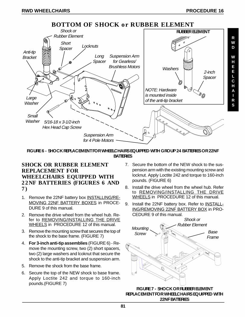
81
5/16-18 x 3-1/2-inchHex Head Cap Screw
ShortSpacer
LargeWasher
Locknuts
LongSpacer
SmallWasher
Anti-tipBracket
Shock orRubber Element
Suspension Armfor Gearless/
Brushless Motors
Suspension Armfor 4 Pole Motors
BOTTOM OF SHOCK or RUBBER ELEMENT
FIGURE 6 - SHOCK REPLACEMENT FOR WHEELCHAIRS EQUIPPED WITH GROUP 24 BATTERIES OR 22NFBATTERIES
2-inchSpacer
Washers
RUBBER ELEMENT
NOTE: Hardwareis mounted insideof the anti-tip bracket
RWD WHEELCHAIRS PROCEDURE 16
RWD
WHEELCHAIRS
SHOCK OR RUBBER ELEMENTREPLACEMENT FORWHEELCHAIRS EQUIPPED WITH22NF BATTERIES (FIGURES 6 AND7)
1. Remove the 22NF battery box INSTALLING/RE-MOVING 22NF BATTERY BOXES in PROCE-DURE 9 of this manual.
2. Remove the drive wheel from the wheel hub. Re-fer to REMOVING/INSTALLING THE DRIVEWHEELS in PROCEDURE 12 of this manual.
3. Remove the mounting screw that secures the top ofthe shock to the base frame. (FIGURE 7)
4. For 3-inch anti-tip assemblies (FIGURE 6) - Re-move the mounting screw, two (2) short spacers,two (2) large washers and lcoknut that secure theshock to the anti-tip bracket and suspension arm.
5. Remove the shock from the base frame.
6. Secure the top of the NEW shock to base frame.Apply Loctite 242 and torque to 160-inchpounds.(FIGURE 7)
7. Secure the bottom of the NEW shock to the sus-pension arm with the existing mounting screw andlocknut. Apply Loctite 242 and torque to 160-inchpounds. (FIGURE 6)
8. Install the drive wheel from the wheel hub. Referto REMOVING/INSTALLING THE DRIVEWHEELS in PROCEDURE 12 of this manual.
9. Install the 22NF battery box. Refer to INSTALL-ING/REMOVING 22NF BATTERY BOX in PRO-CEDURE 9 of this manual.
FIGURE 7 - SHOCK OR RUBBER ELEMENTREPLACEMENT FOR WHEELCHAIRS EQUIPPED WITH
22NF BATTERIES
BaseFrame
MountingScrew
Shock orRubber Element
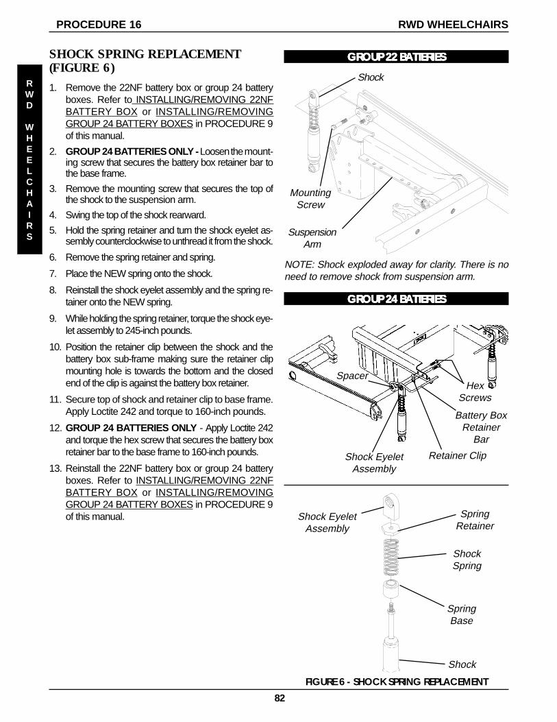
82
RWD WHEELCHAIRSPROCEDURE 16
RWD
WHEELCHAIRS
SHOCK SPRING REPLACEMENT(FIGURE 6)
1. Remove the 22NF battery box or group 24 batteryboxes. Refer to INSTALLING/REMOVING 22NFBATTERY BOX or INSTALLING/REMOVINGGROUP 24 BATTERY BOXES in PROCEDURE 9of this manual.
2. GROUP 24 BATTERIES ONLY - Loosen the mount-ing screw that secures the battery box retainer bar tothe base frame.
3. Remove the mounting screw that secures the top ofthe shock to the suspension arm.
4. Swing the top of the shock rearward.
5. Hold the spring retainer and turn the shock eyelet as-sembly counterclockwise to unthread it from the shock.
6. Remove the spring retainer and spring.
7. Place the NEW spring onto the shock.
8. Reinstall the shock eyelet assembly and the spring re-tainer onto the NEW spring.
9. While holding the spring retainer, torque the shock eye-let assembly to 245-inch pounds.
10. Position the retainer clip between the shock and thebattery box sub-frame making sure the retainer clipmounting hole is towards the bottom and the closedend of the clip is against the battery box retainer.
11. Secure top of shock and retainer clip to base frame.Apply Loctite 242 and torque to 160-inch pounds.
12. GROUP 24 BATTERIES ONLY - Apply Loctite 242and torque the hex screw that secures the battery boxretainer bar to the base frame to 160-inch pounds.
13. Reinstall the 22NF battery box or group 24 batteryboxes. Refer to INSTALLING/REMOVING 22NFBATTERY BOX or INSTALLING/REMOVINGGROUP 24 BATTERY BOXES in PROCEDURE 9of this manual.
Battery BoxRetainer
Bar
HexScrews
Spacer
FIGURE 6 - SHOCK SPRING REPLACEMENT
Shock EyeletAssembly
Retainer Clip
Shock EyeletAssembly
SpringRetainer
ShockSpring
SpringBase
Shock
GRGRGRGRGROUP 22 BOUP 22 BOUP 22 BOUP 22 BOUP 22 BAAAAATTERIESTTERIESTTERIESTTERIESTTERIES
NOTE: Shock exploded away for clarity. There is noneed to remove shock from suspension arm.
SuspensionArm
MountingScrew
Shock
GRGRGRGRGROUP 24 BOUP 24 BOUP 24 BOUP 24 BOUP 24 BAAAAATTERIESTTERIESTTERIESTTERIESTTERIES
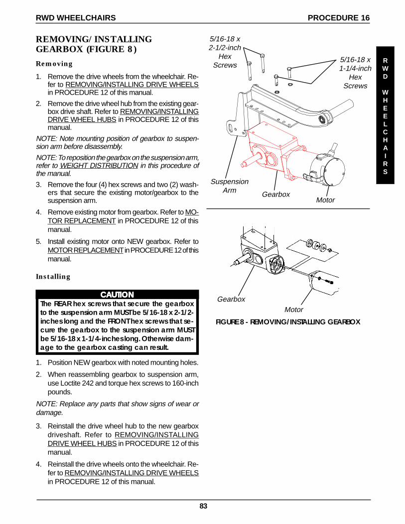
83
REMOVING/INSTALLINGGEARBOX (FIGURE 8)
Removing
1. Remove the drive wheels from the wheelchair. Re-fer to REMOVING/INSTALLING DRIVE WHEELSin PROCEDURE 12 of this manual.
2. Remove the drive wheel hub from the existing gear-box drive shaft. Refer to REMOVING/INSTALLINGDRIVE WHEEL HUBS in PROCEDURE 12 of thismanual.
NOTE: Note mounting position of gearbox to suspen-sion arm before disassembly.
NOTE: To reposition the gearbox on the suspension arm,refer to WEIGHT DISTRIBUTION in this procedure ofthe manual.
3. Remove the four (4) hex screws and two (2) wash-ers that secure the existing motor/gearbox to thesuspension arm.
4. Remove existing motor from gearbox. Refer to MO-TOR REPLACEMENT in PROCEDURE 12 of thismanual.
5. Install existing motor onto NEW gearbox. Refer toMOTOR REPLACEMENT in PROCEDURE 12 of thismanual.
Installing
CCCCCAAAAAUTIONUTIONUTIONUTIONUTIONThe REAR hex screws that secure the gearboxto the suspension arm MUST be 5/16-18 x 2-1/2-inches long and the FRONT hex screws that se-cure the gearbox to the suspension arm MUSTbe 5/16-18 x 1-1/4-inches long. Otherwise dam-age to the gearbox casting can result.
1. Position NEW gearbox with noted mounting holes.
2. When reassembling gearbox to suspension arm,use Loctite 242 and torque hex screws to 160-inchpounds.
NOTE: Replace any parts that show signs of wear ordamage.
3. Reinstall the drive wheel hub to the new gearboxdriveshaft. Refer to REMOVING/INSTALLINGDRIVE WHEEL HUBS in PROCEDURE 12 of thismanual.
4. Reinstall the drive wheels onto the wheelchair. Re-fer to REMOVING/INSTALLING DRIVE WHEELSin PROCEDURE 12 of this manual.
5/16-18 x1-1/4-inch
HexScrews
Gearbox
SuspensionArm
FIGURE 8 - REMOVING/INSTALLING GEARBOX
Motor
5/16-18 x2-1/2-inch
HexScrews
GearboxMotor
RWD WHEELCHAIRS PROCEDURE 16
RWD
WHEELCHAIRS
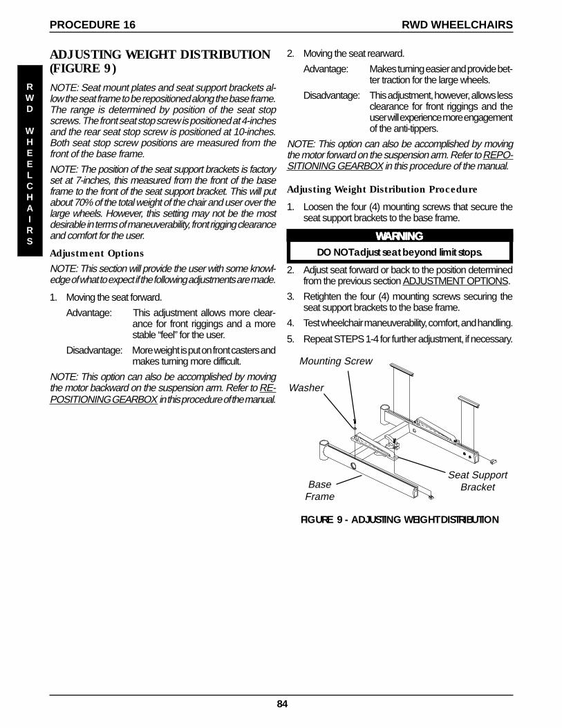
84
ADJUSTING WEIGHT DISTRIBUTION(FIGURE 9)NOTE: Seat mount plates and seat support brackets al-low the seat frame to be repositioned along the base frame.The range is determined by position of the seat stopscrews. The front seat stop screw is positioned at 4-inchesand the rear seat stop screw is positioned at 10-inches.Both seat stop screw positions are measured from thefront of the base frame.
NOTE: The position of the seat support brackets is factoryset at 7-inches, this measured from the front of the baseframe to the front of the seat support bracket. This will putabout 70% of the total weight of the chair and user over thelarge wheels. However, this setting may not be the mostdesirable in terms of maneuverability, front rigging clearanceand comfort for the user.
Adjustment Options
NOTE: This section will provide the user with some knowl-edge of what to expect if the following adjustments are made.
1. Moving the seat forward.
Advantage: This adjustment allows more clear-ance for front riggings and a morestable “feel” for the user.
Disadvantage: More weight is put on front casters andmakes turning more difficult.
NOTE: This option can also be accomplished by movingthe motor backward on the suspension arm. Refer to RE-POSITIONING GEARBOX in this procedure of the manual.
Washer
BaseFrame
FIGURE 9 - ADJUSTING WEIGHT DISTRIBUTION
Seat SupportBracket
Mounting Screw
2. Moving the seat rearward.
Advantage: Makes turning easier and provide bet-ter traction for the large wheels.
Disadvantage: This adjustment, however, allows lessclearance for front riggings and theuser will experience more engagementof the anti-tippers.
NOTE: This option can also be accomplished by movingthe motor forward on the suspension arm. Refer to REPO-SITIONING GEARBOX in this procedure of the manual.
Adjusting Weight Distribution Procedure
1. Loosen the four (4) mounting screws that secure theseat support brackets to the base frame.
WWWWWARNINGARNINGARNINGARNINGARNINGDO NOT adjust seat beyond limit stops.
2. Adjust seat forward or back to the position determinedfrom the previous section ADJUSTMENT OPTIONS.
3. Retighten the four (4) mounting screws securing theseat support brackets to the base frame.
4. Test wheelchair maneuverability, comfort, and handling.
5. Repeat STEPS 1-4 for further adjustment, if necessary.
RWD WHEELCHAIRSPROCEDURE 16
RWD
WHEELCHAIRS
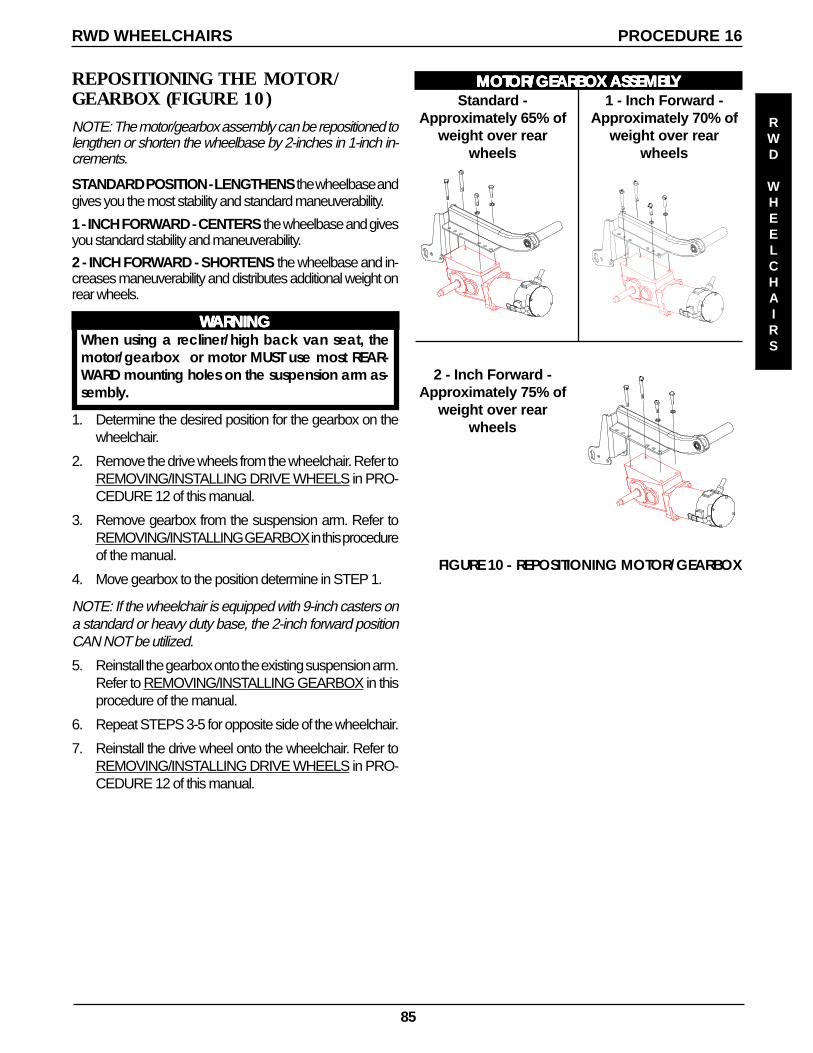
85
REPOSITIONING THE MOTOR/GEARBOX (FIGURE 10)NOTE: The motor/gearbox assembly can be repositioned tolengthen or shorten the wheelbase by 2-inches in 1-inch in-crements.
STANDARD POSITION - LENGTHENS the wheelbase andgives you the most stability and standard maneuverability.
1 - INCH FORWARD - CENTERS the wheelbase and givesyou standard stability and maneuverability.
2 - INCH FORWARD - SHORTENS the wheelbase and in-creases maneuverability and distributes additional weight onrear wheels.
FIGURE 10 - REPOSITIONING MOTOR/GEARBOX
Standard -Approximately 65% of
weight over rearwheels
1 - Inch Forward -Approximately 70% of
weight over rearwheels
2 - Inch Forward -Approximately 75% of
weight over rearwheels
MOMOMOMOMOTTTTTOR/GEARBOOR/GEARBOOR/GEARBOOR/GEARBOOR/GEARBOX X X X X ASSEMBLASSEMBLASSEMBLASSEMBLASSEMBLYYYYY
WWWWWARNINGARNINGARNINGARNINGARNINGWhen using a recliner/high back van seat, themotor/gearbox or motor MUST use most REAR-WARD mounting holes on the suspension arm as-sembly.
1. Determine the desired position for the gearbox on thewheelchair.
2. Remove the drive wheels from the wheelchair. Refer toREMOVING/INSTALLING DRIVE WHEELS in PRO-CEDURE 12 of this manual.
3. Remove gearbox from the suspension arm. Refer toREMOVING/INSTALLING GEARBOX in this procedureof the manual.
4. Move gearbox to the position determine in STEP 1.
NOTE: If the wheelchair is equipped with 9-inch casters ona standard or heavy duty base, the 2-inch forward positionCAN NOT be utilized.
5. Reinstall the gearbox onto the existing suspension arm.Refer to REMOVING/INSTALLING GEARBOX in thisprocedure of the manual.
6. Repeat STEPS 3-5 for opposite side of the wheelchair.
7. Reinstall the drive wheel onto the wheelchair. Refer toREMOVING/INSTALLING DRIVE WHEELS in PRO-CEDURE 12 of this manual.
RWD WHEELCHAIRS PROCEDURE 16
RWD
WHEELCHAIRS

86
1-inch forward -Approximately 75%
of weight overrear wheels
Standard -Approximately 70%
of weight overrear wheels
1 - Inch Rearward -Approximately 65%
of weight overrear wheels
REPOSITIONING THE GEARLESS/BRUSHLESS MOTOR (FIGURE 11,12)
Acceptable mounting positions for the gearless/brushless motor.
NOTE: On models equipped with ifixed back only, the gearless/brushless motor can be repositioned to lengthen orshorten the wheelbase by 2-inches in 1-inch increments.
ARROW AND RANGER X WITH FIXED BACK
STANDARD POSITION - CENTERS the wheelbaseand gives you standard stability and maneuverability.
1-INCH REARWARD- LENGTHENS the wheelbaseand gives you the most stability and standard maneu-verability.
1-INCH FORWARD - SHORTENS the wheelbase andincreases maneuverability and distributes additionalweight on rear wheels.
ARROW, RANGER X,AND TORQUE SP WITHWITH MANUAL RECLINER, 2G POWERED SEATIING
SYSTEM, OR HIGH BACK VAN SEAT
STANDARD POSITION - LENGTHENS the wheelbaseand gives you the most stability and standard maneu-verability.
1-INCH FORWARD - CENTERS the wheelbase andgives you standard stability and maneuverability.
2-INCH FORWARD - SHORTENS the wheelbase and in-creases maneuverability and distributes additional weight onrear wheels.
1 - Inch Forward -Approximately 70%
of weight overrear wheels
2 - Inch Forward -Approximately 75%
of weight overrear wheels
Standard -Approximately 65%
of weight overrear wheels
FIGURE 11 - REPOSITIONING THE GEARLESS/BRUSHLESS MOTOR
RWD WHEELCHAIRSPROCEDURE 16
RWD
WHEELCHAIRS
FORWARD
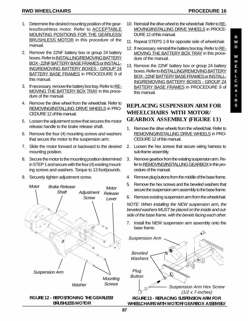
87
AdjustmentScrew
1. Determine the desired mounting position of the gear-less/brushless motor. Refer to ACCEPTABLEMOUNTING POSITIONS FOR THE GEARLESS/BRUSHLESS MOTOR in this procedure of themanual.
2. Remove the 22NF battery box or group 24 batteryboxes. Refer to INSTALLING/REMOVING BATTERYBOX - 22NF BATTERY BASE FRAMES or INSTALL-ING/REMOVING BATTERY BOXES - GROUP 24BATTERY BASE FRAMES in PROCEDURE 9 ofthis manual.
3. If necessary, remove the battery box tray. Refer to RE-MOVING THE BATTERY BOX TRAY in this proce-dure of the manual.
4. Remove the drive wheel from the wheelchair. Refer toREMOVING/INSTALLING DRIVE WHEELS in PRO-CEDURE 12 of this manual.
5. Loosen the adjustment screw that secures the motorrelease handle to the brake release shaft.
6. Remove the four (4) mounting screws and washersthat secure the motor to the suspension arm.
7. Slide the motor forward or backward to the desiredmounting position.
8. Secure the motor to the mounting position determinedin STEP 1 and secure with the four (4) existing mount-ing screws and washers. Torque to 13 foot/pounds.
9. Securely tighten adjustment screw.
FIGURE 12 - REPOSITIONING THE GEARLESS/BRUSHLESS MOTOR
10. Reinstall the drive wheel to the wheelchair. Refer to RE-MOVING/INSTALLING DRIVE WHEELS in PROCE-DURE 12 of this manual.
11. Repeat STEPS 1-9 for opposite side of wheelchair.
12. If necessary, reinstall the battery box tray. Refer to RE-MOVING THE BATTERY BOX TRAY in this proce-dure of the manual.
13. Remove the 22NF battery box or group 24 batteryboxes. Refer to INSTALLING/REMOVING BATTERYBOX - 22NF BATTERY BASE FRAMES or INSTALL-ING/REMOVING BATTERY BOXES - GROUP 24BATTERY BASE FRAMES in PROCEDURE 9 ofthis manual.
MotorReleaseLever
Brake ReleaseShaft
MountingScrewsWasher
Suspension Arm
Motor
Suspension Arm Hex Screw(1/2 x 7-inches)
FIGURE 13 - REPLACING SUSPENSION ARM FORWHEELCHAIRS WITH MOTOR/GEARBOX ASSEMBLY
Suspension Arm
PlugButton
BeveledWashers
REPLACING SUSPENSION ARM FORWHEELCHAIRS WITH MOTOR/GEARBOX ASSEMBLY (FIGURE 13)
1. Remove the drive wheels from the wheelchair. Refer toREMOVING/INSTALLING DRIVE WHEELS in PRO-CEDURE 12 of this manual.
2. Loosen the hex screws that secure wiring harness tosub-frame assembly.
3. Remove gearbox from the existing suspension arm. Re-fer to REMOVING/INSTALLING GEARBOX in this pro-cedure of the manual.
4. Remove plug buttons from the middle of the base frame.
5. Remove the hex screws and the beveled washers thatsecure the suspension arm assembly to the base frame.
6. Remove existing suspension arm from the wheelchair.
NOTE: When installing the NEW suspension arm, thebeveled washers MUST be placed on the inside and out-side of the base frame, with the bevels facing each other.
7. Install the NEW suspension arm assembly onto thebase frame.
RWD WHEELCHAIRS PROCEDURE 16
RWD
WHEELCHAIRS
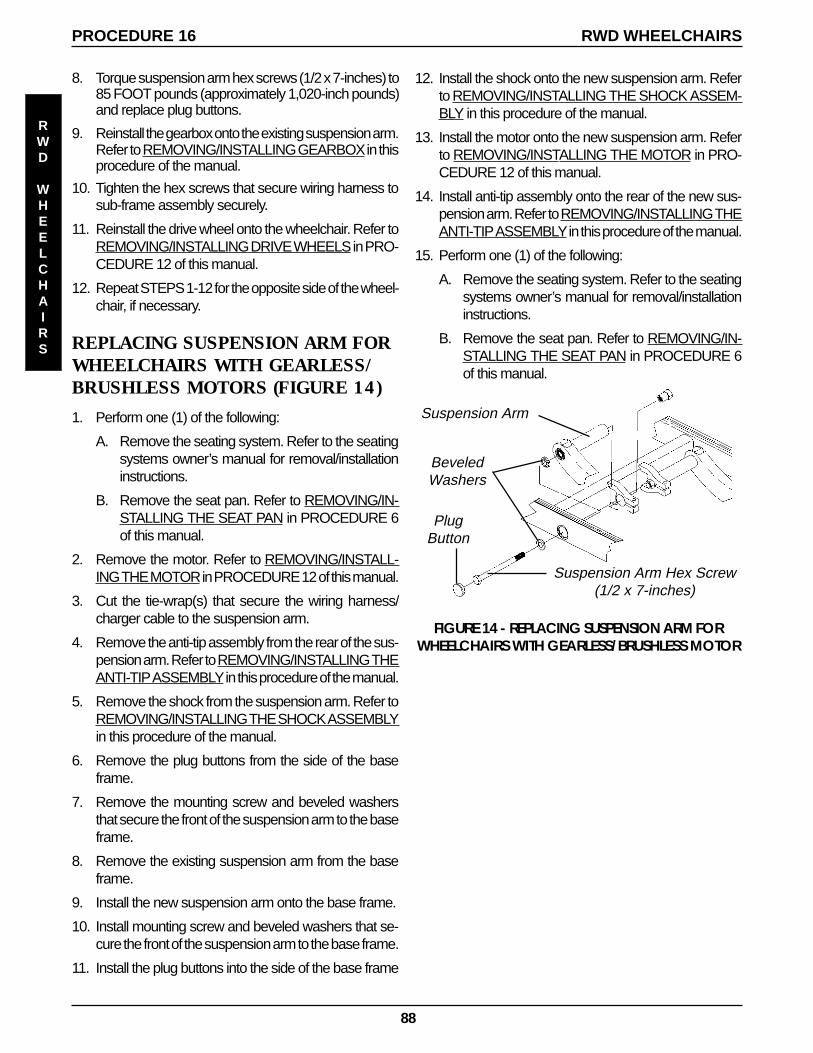
88
12. Install the shock onto the new suspension arm. Referto REMOVING/INSTALLING THE SHOCK ASSEM-BLY in this procedure of the manual.
13. Install the motor onto the new suspension arm. Referto REMOVING/INSTALLING THE MOTOR in PRO-CEDURE 12 of this manual.
14. Install anti-tip assembly onto the rear of the new sus-pension arm. Refer to REMOVING/INSTALLING THEANTI-TIP ASSEMBLY in this procedure of the manual.
15. Perform one (1) of the following:
A. Remove the seating system. Refer to the seatingsystems owner’s manual for removal/installationinstructions.
B. Remove the seat pan. Refer to REMOVING/IN-STALLING THE SEAT PAN in PROCEDURE 6of this manual.
8. Torque suspension arm hex screws (1/2 x 7-inches) to85 FOOT pounds (approximately 1,020-inch pounds)and replace plug buttons.
9. Reinstall the gearbox onto the existing suspension arm.Refer to REMOVING/INSTALLING GEARBOX in thisprocedure of the manual.
10. Tighten the hex screws that secure wiring harness tosub-frame assembly securely.
11. Reinstall the drive wheel onto the wheelchair. Refer toREMOVING/INSTALLING DRIVE WHEELS in PRO-CEDURE 12 of this manual.
12. Repeat STEPS 1-12 for the opposite side of the wheel-chair, if necessary.
REPLACING SUSPENSION ARM FORWHEELCHAIRS WITH GEARLESS/BRUSHLESS MOTORS (FIGURE 14)
1. Perform one (1) of the following:
A. Remove the seating system. Refer to the seatingsystems owner’s manual for removal/installationinstructions.
B. Remove the seat pan. Refer to REMOVING/IN-STALLING THE SEAT PAN in PROCEDURE 6of this manual.
2. Remove the motor. Refer to REMOVING/INSTALL-ING THE MOTOR in PROCEDURE 12 of this manual.
3. Cut the tie-wrap(s) that secure the wiring harness/charger cable to the suspension arm.
4. Remove the anti-tip assembly from the rear of the sus-pension arm. Refer to REMOVING/INSTALLING THEANTI-TIP ASSEMBLY in this procedure of the manual.
5. Remove the shock from the suspension arm. Refer toREMOVING/INSTALLING THE SHOCK ASSEMBLYin this procedure of the manual.
6. Remove the plug buttons from the side of the baseframe.
7. Remove the mounting screw and beveled washersthat secure the front of the suspension arm to the baseframe.
8. Remove the existing suspension arm from the baseframe.
9. Install the new suspension arm onto the base frame.
10. Install mounting screw and beveled washers that se-cure the front of the suspension arm to the base frame.
11. Install the plug buttons into the side of the base frame
Suspension Arm Hex Screw(1/2 x 7-inches)
FIGURE 14 - REPLACING SUSPENSION ARM FORWHEELCHAIRS WITH GEARLESS/BRUSHLESS MOTOR
Suspension Arm
PlugButton
BeveledWashers
RWD WHEELCHAIRSPROCEDURE 16
RWD
WHEELCHAIRS
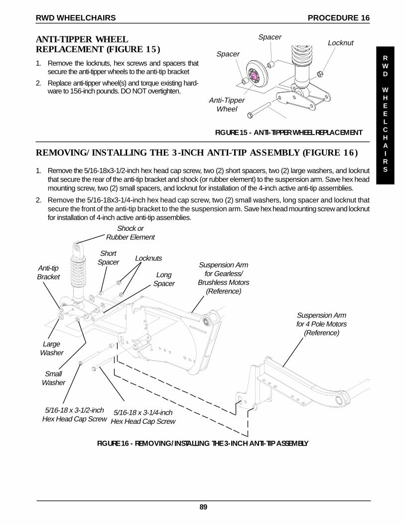
89
Anti-TipperWheel
LocknutANTI-TIPPER WHEELREPLACEMENT (FIGURE 15)1. Remove the locknuts, hex screws and spacers that
secure the anti-tipper wheels to the anti-tip bracket
2. Replace anti-tipper wheel(s) and torque existing hard-ware to 156-inch pounds. DO NOT overtighten.
Spacer
FIGURE 15 - ANTI-TIPPER WHEEL REPLACEMENT
Spacer
RWD WHEELCHAIRS PROCEDURE 16
FIGURE 16 - REMOVING/INSTALLING THE 3-INCH ANTI-TIP ASSEMBLY
5/16-18 x 3-1/2-inchHex Head Cap Screw
ShortSpacer
LargeWasher
Locknuts
LongSpacer
SmallWasher
Anti-tipBracket
Shock orRubber Element
Suspension Armfor Gearless/
Brushless Motors(Reference)
Suspension Armfor 4 Pole Motors
(Reference)
5/16-18 x 3-1/4-inchHex Head Cap Screw
REMOVING/INSTALLING THE 3-INCH ANTI-TIP ASSEMBLY (FIGURE 16)
1. Remove the 5/16-18x3-1/2-inch hex head cap screw, two (2) short spacers, two (2) large washers, and locknutthat secure the rear of the anti-tip bracket and shock (or rubber element) to the suspension arm. Save hex headmounting screw, two (2) small spacers, and locknut for installation of the 4-inch active anti-tip assemblies.
2. Remove the 5/16-18x3-1/4-inch hex head cap screw, two (2) small washers, long spacer and locknut thatsecure the front of the anti-tip bracket to the the suspension arm. Save hex head mounting screw and locknutfor installation of 4-inch active anti-tip assemblies.
RWD
WHEELCHAIRS

90
NOTES
NOTES
NOTES
91
LIMITED WARRANTYPLEASE NOTE: THE WARRANTY BELOW HAS BEEN DRAFTED TO COMPLY WITH FEDERAL LAW APPLICABLETO PRODUCTS MANUFACTURED AFTER JULY 4, 1975.
This warranty is extended only to the original purchaser/user of our products.
This warranty gives you specific legal rights and you may also have other legal rights which vary fromstate to state.
Invacare warrants seat frame to be free from defects in materials and workmanship for a period ofthree (3) years from date of purchase; that electrical components are warranted for a period of one(1) year; gearbox/motors for a period of 18 months; and gearless/brushless motors for five (5) years fromthe date of purchase; and the base frame for the life of the product; all remaining components (in-cluding gas cylinders and motor lock pads) for one (1) year from the date of purchase except uphol-stered materials, padded materials and tires/wheels. If within such warranty period any such productshall be proven to be defective, such product shall be repaired or replaced, at Invacare's option. Thiswarranty does not include any labor or shipping charges incurred in replacement part installation orrepair of any such product. Invacare's sole obligation and your exclusive remedy under this warrantyshall be limited to such repair and/or replacement.
This warranty pertains to Arrow Series, Ranger X Series and Torque Series Only!
For warranty service, please contact the dealer from whom you purchased your Invacare product. Inthe event you do not receive satisfactory warranty service, please write directly to Invacare at theaddress at the bottom of the back cover. Provide dealer’s name, address, date of purchase, indicatenature of the defect and, if the product is serialized, indicate the serial number. Do not return productsto our factory without our prior consent.
LIMITATIONS AND EXCLUSIONS: THE FOREGOING WARRANTY SHALL NOT APPLY TO SERIAL NUMBEREDPRODUCTS IF THE SERIAL NUMBER HAS BEEN REMOVED OR DEFACED, PRODUCTS SUBJECTED TO NEGLI-GENCE, ACCIDENT, IMPROPER OPERATION, MAINTENANCE OR STORAGE, COMMERCIAL OR INSTITU-TIONAL USE, PRODUCTS MODIFIED WITHOUT INVACARE'S EXPRESS WRITTEN CONSENT INCLUDING, BUTNOT LIMITED TO, MODIFICATION THROUGH THE USE OF UNAUTHORIZED PARTS OR ATTACHMENTS; PROD-UCTS DAMAGED BY REASON OF REPAIRS MADE TO ANY COMPONENT WITHOUT THE SPECIFIC CONSENTOF INVACARE, OR TO A PRODUCT DAMAGED BY CIRCUMSTANCES BEYOND INVACARE'S CONTROL,AND SUCH EVALUATION WILL BE SOLELY DETERMINED BY INVACARE. THE WARRANTY SHALL NOT APPLYTO PROBLEMS ARISING FROM NORMAL WEAR OR FAILURE TO ADHERE TO THESE INSTRUCTIONS.
THE FOREGOING WARRANTY IS EXCLUSIVE AND IN LIEU OF ALL OTHER EXPRESS WARRANTIES. IMPLIEDWARRANTIES, IF ANY, INCLUDING THE IMPLIED WARRANTIES OF MERCHANTABILITY AND FITNESS FOR APARTICULAR PURPOSE, SHALL NOT EXTEND BEYOND THE DURATION OF THE EXPRESS WARRANTY PRO-VIDED HEREIN AND THE REMEDY FOR VIOLATIONS OF ANY IMPLIED WARRANTY SHALL BE LIMITED TOREPAIR OR REPLACEMENT OF THE DEFECTIVE PRODUCT PURSUANT TO THE TERMS CONTAINED HEREIN.INVACARE SHALL NOT BE LIABLE FOR ANY CONSEQUENTIAL OR INCIDENTAL DAMAGES WHATSOEVER.
THIS WARRANTY SHALL BE EXTENDED TO COMPLY WITH STATE/PROVINCIAL LAWS AND REQUIREMENTS.
WARRANTY
WARRANTY

Invacare Corporation www.invacare.com
USA Canada Invacare, Storm Series, Arrow are registered trademarksOne Invacare Way 5970 Chedworth Way and Ranger X, Torque and Yes, You can are trademarks InvacareElyria, Ohio USA Mississauga, Ontario Corporation.44036-2125 L5R 3T9, Canada Loctite is a registered trademrk of Loctite Corporation.800-333-6900 905-890-8838 ©
2001 Invacare CorporationForm No. 01-015 Part No. 1104849 Rev A (1)-4/01