Embed Size (px)
DESCRIPTION
3G RF Optimization
Citation preview
3G RF OPTIMIZATIONJ. A. SANTOS
MARCH 2015
OBJECTIVES:
• Provide an overview of the UMTS Technology
• Be familiar with the UMTS Network architecture and releases
• Introduce metrics for walktest
• Introduce metrics for OSS KPI monitoring
• Establish a process of 3G RF optimization
• Discuss different types of Handover in UMTS
• Familiarize with different parameters associated with each handover type
UMTS OVERVIEW
• UMTS – Universal Mobile Telecommunication System. It is a 3G mobile wireless solution that complies with the IMT-2000 standard which is designed to support multiple services with individual QoS requirements
• WCDMA is a Radio Access Technology used in UMTS radio Access Network
• The WCDMA RAN consists of the following:• User Equipment (UE)
• Base Stations (Node B)
• Radio Network Controllers (RNC)
• UMTS and WCDMA are often used interchangeably, but these are actually two different concepts.
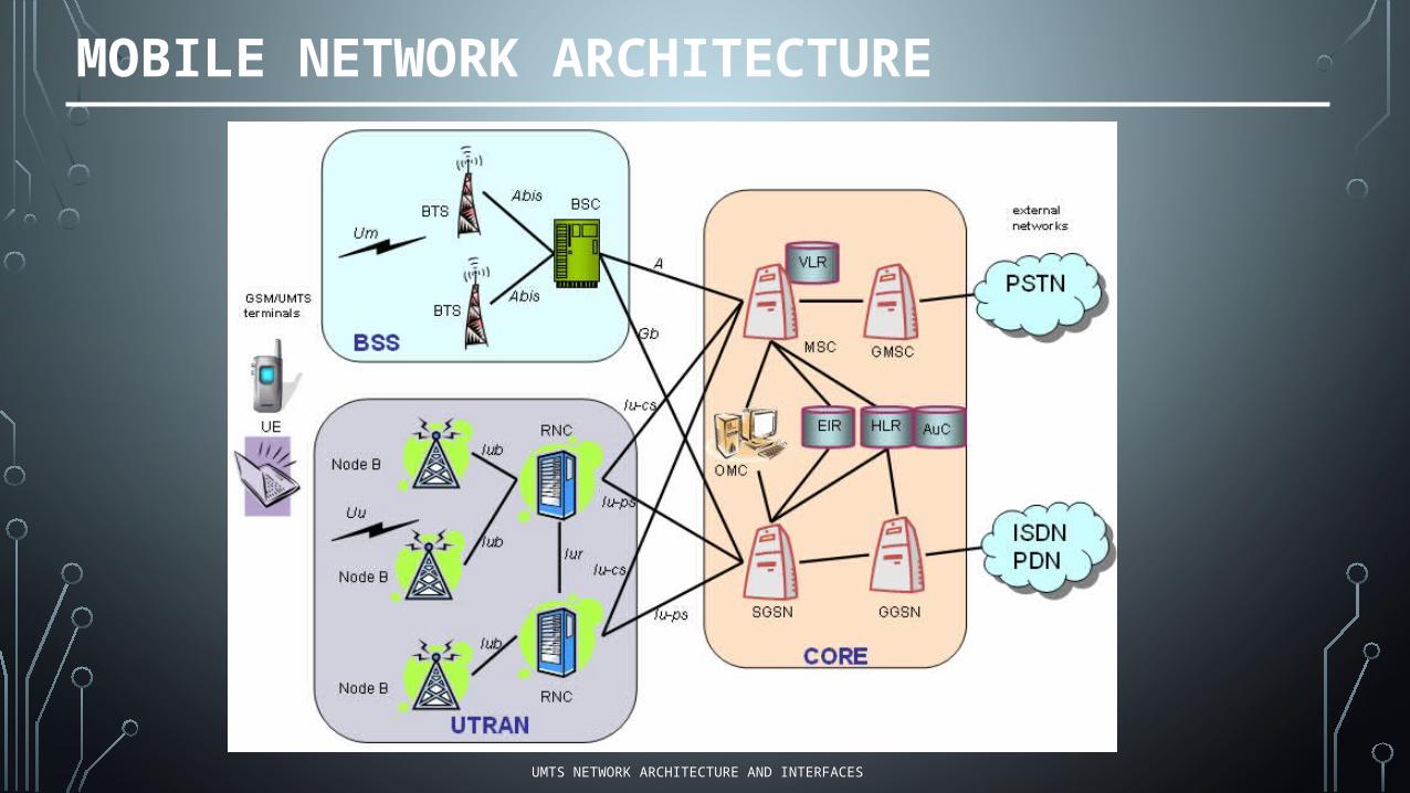
MOBILE NETWORK ARCHITECTURE
UMTS NETWORK ARCHITECTURE AND INTERFACES
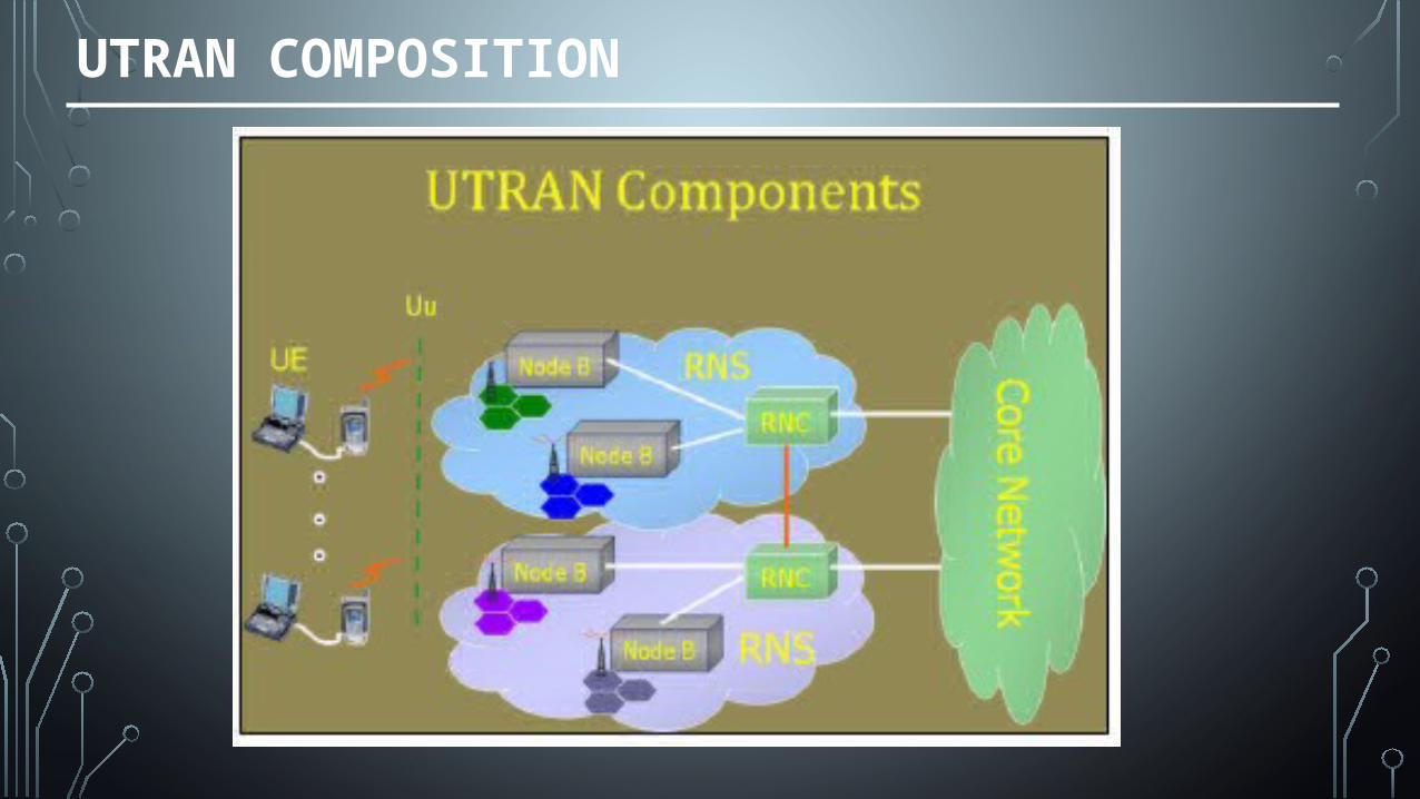
UTRAN COMPOSITION
UMTS RELEASE AND FEATURES:
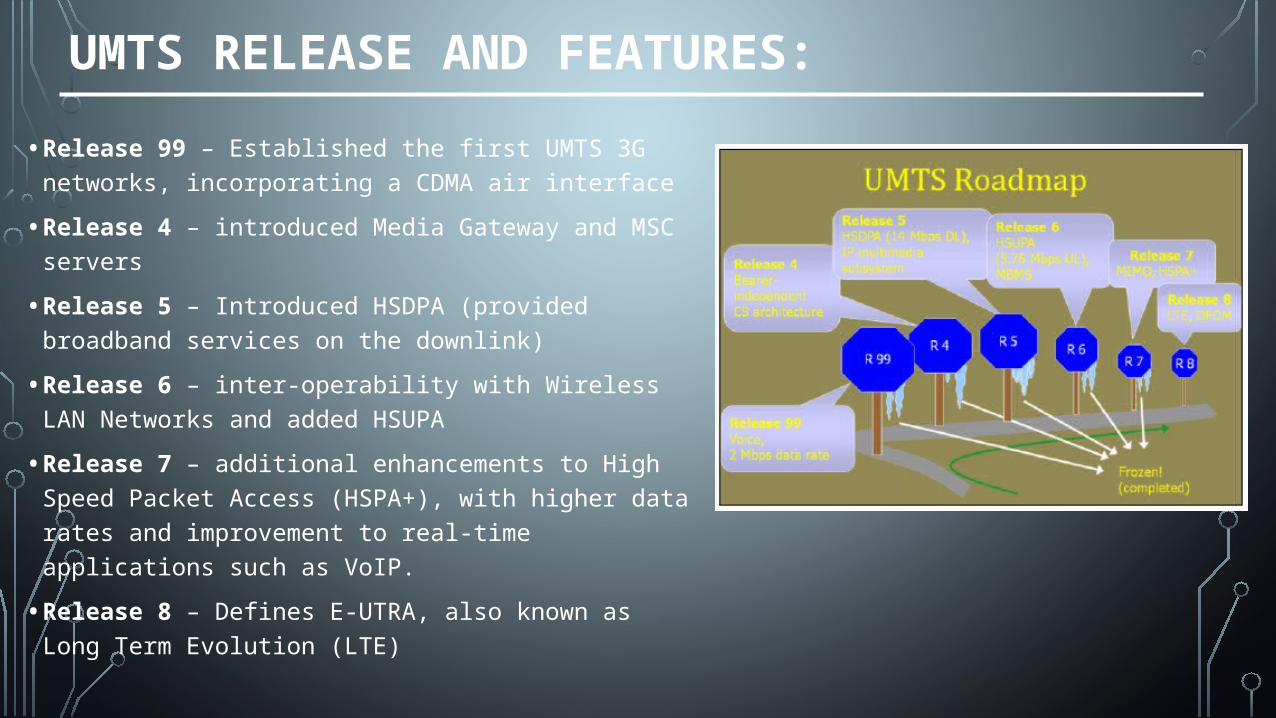
• Release 99 – Established the first UMTS 3G networks, incorporating a CDMA air interface
• Release 4 – introduced Media Gateway and MSC servers
• Release 5 – Introduced HSDPA (provided broadband services on the downlink)
• Release 6 – inter-operability with Wireless LAN Networks and added HSUPA
• Release 7 – additional enhancements to High Speed Packet Access (HSPA+), with higher data rates and improvement to real-time applications such as VoIP.
• Release 8 – Defines E-UTRA, also known as Long Term Evolution (LTE)
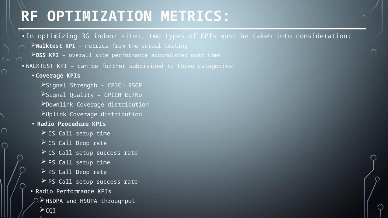
RF OPTIMIZATION METRICS:• In optimizing 3G indoor sites, two types of KPIs must be taken into consideration:
Walktest KPI – metrics from the actual testing
OSS KPI – overall site performance accumulated over time
• WALKTEST KPI – can be further subdivided to three categories:
• Coverage KPIs
Signal Strength – CPICH RSCP
Signal Quality – CPICH Ec/No
Downlink Coverage distribution
Uplink Coverage distribution
• Radio Procedure KPIs
CS Call setup time
CS Call Drop rate
CS Call setup success rate
PS Call setup time
PS Call Drop rate
PS Call setup success rate
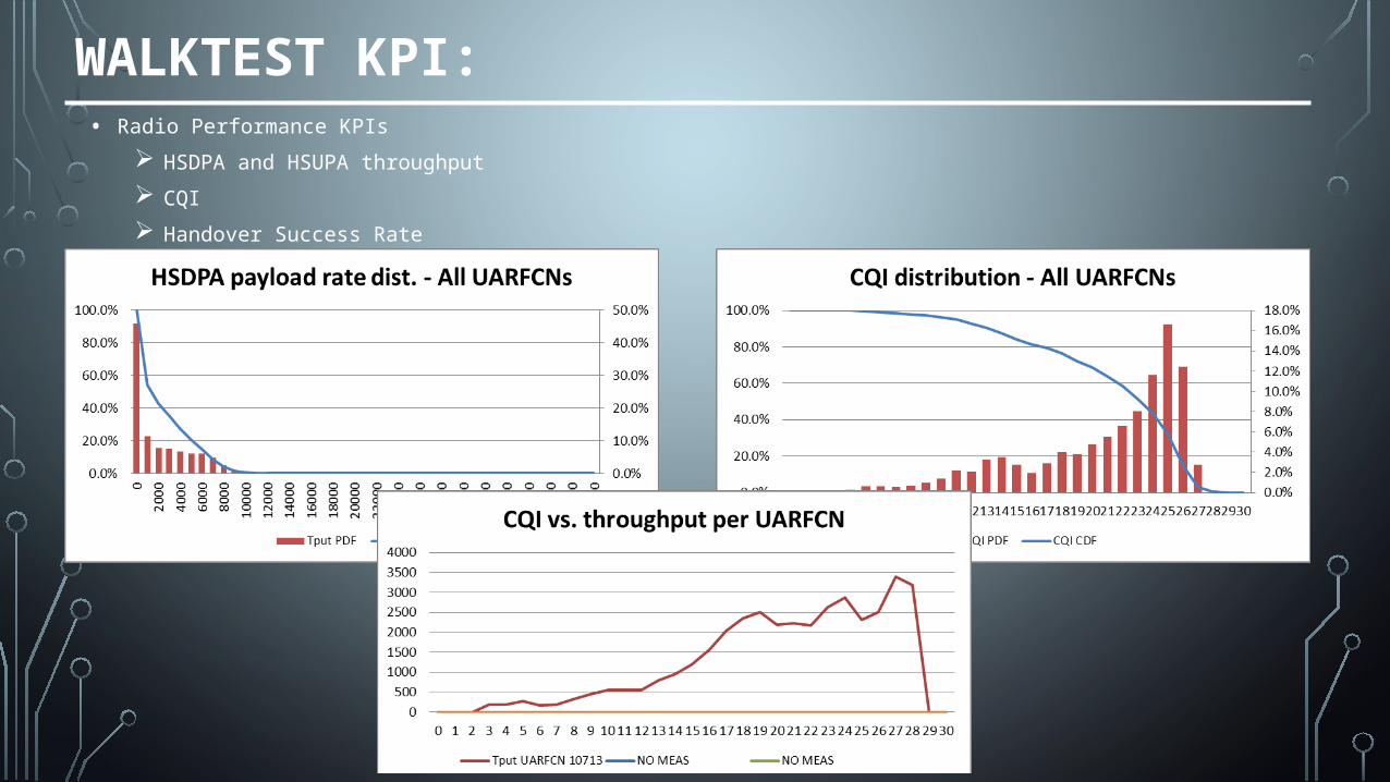
• Radio Performance KPIs
HSDPA and HSUPA throughput
CQI
Handover Success Rate
WALKTEST KPI:
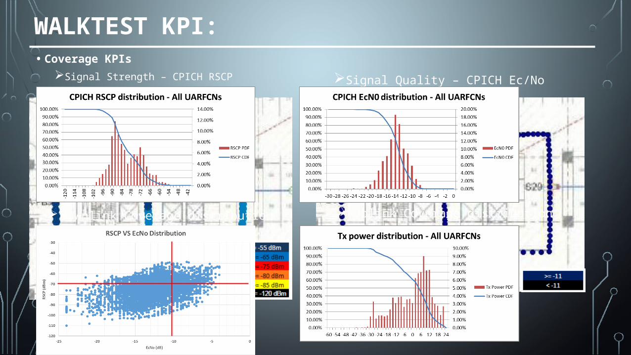
Uplink Coverage distribution
• Coverage KPIs
Signal Strength – CPICH RSCP Signal Quality – CPICH Ec/No
Downlink Coverage distribution
WALKTEST KPI:
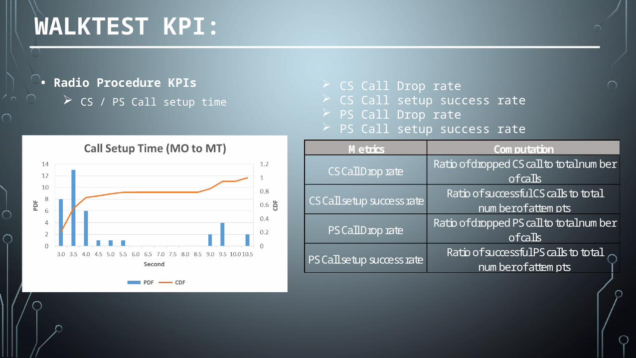
• Radio Procedure KPIs
CS / PS Call setup time
CS Call Drop rate CS Call setup success rate PS Call Drop rate PS Call setup success rate Metrics Computation
CS Call Drop rateRatio of dropped CS call to total number
of calls
CS Call setup success rateRatio of successful CS calls to total
number of attempts
PS Call Drop rateRatio of dropped PS call to total number
of calls
PS Call setup success rateRatio of successful PS calls to total
number of attempts
WALKTEST KPI:• Radio Performance KPIs
HSDPA and HSUPA throughput
CQI
Handover Success Rate
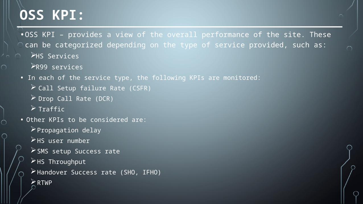
OSS KPI:• OSS KPI – provides a view of the overall performance of the site. These can be categorized
depending on the type of service provided, such as:HS Services
R99 services
• In each of the service type, the following KPIs are monitored:
Call Setup failure Rate (CSFR)
Drop Call Rate (DCR)
Traffic
• Other KPIs to be considered are:
Propagation delay
HS user number
SMS setup Success rate
HS Throughput
Handover Success rate (SHO, IFHO)
RTWP
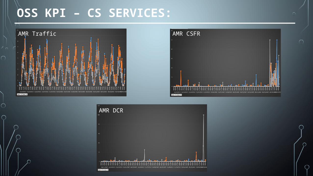
OSS KPI – CS SERVICES:
AMR Traffic AMR CSFR
AMR DCR
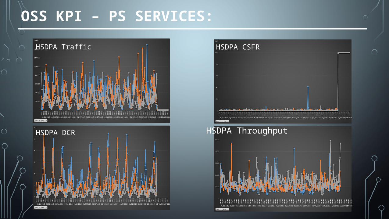
OSS KPI – PS SERVICES:
HSDPA DCR HSDPA Throughput
HSDPA Traffic HSDPA CSFR
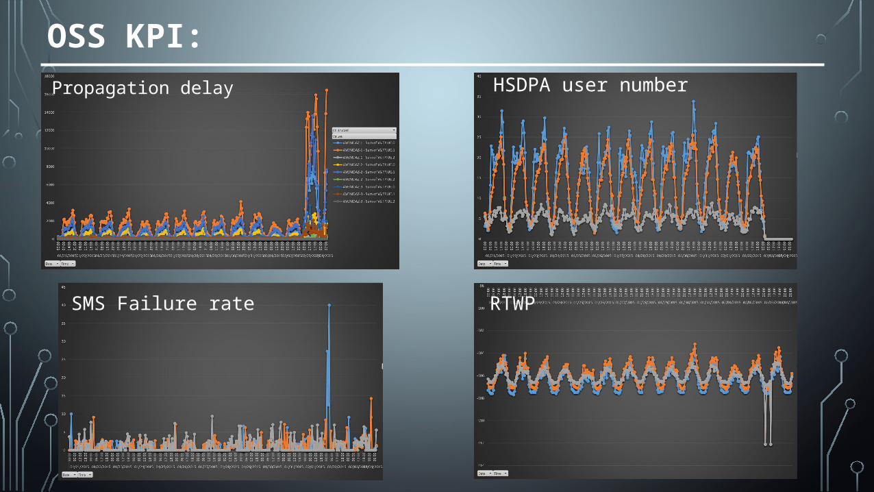
OSS KPI:
Propagation delay HSDPA user number
HSDPA DCR
SMS Failure rate RTWP
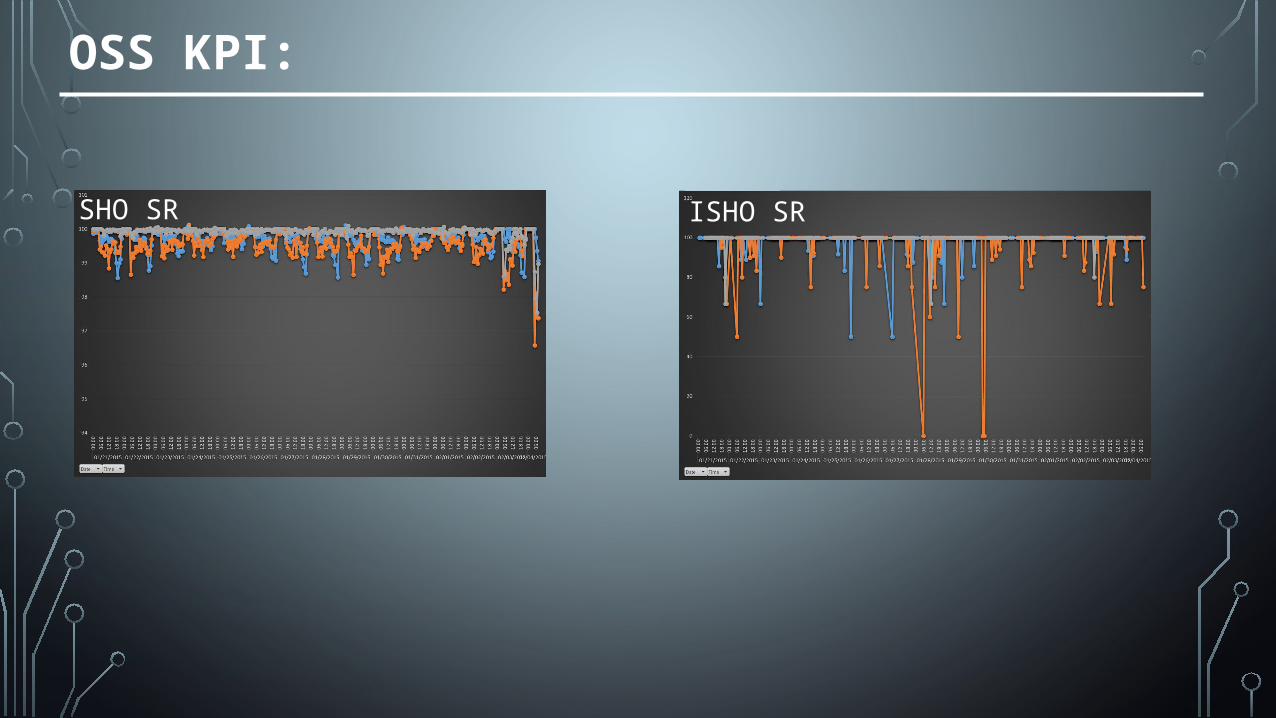
OSS KPI:
SHO SR ISHO SR
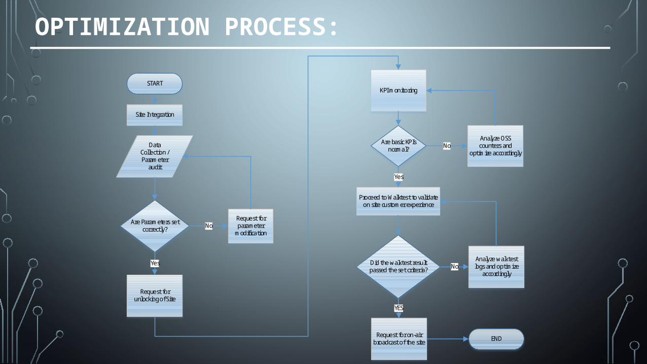
OPTIMIZATION PROCESS:
START
Site Integration
Data Collection / Parameter
audit
Are Parameters set correctly?
Request for unlocking of Site
Request for parameter
modificationNo
Yes
KPI monitoring
Are basic KPIs normal?
Analyze OSS counters and
optimize accordingly
Proceed to Walktest to validate on site customer experience
No
Yes
Did the walktest result passed the set criteria?
Analyze walktest logs and optimize
accordingly
Request for on-air broadcast of the site END
YES
No
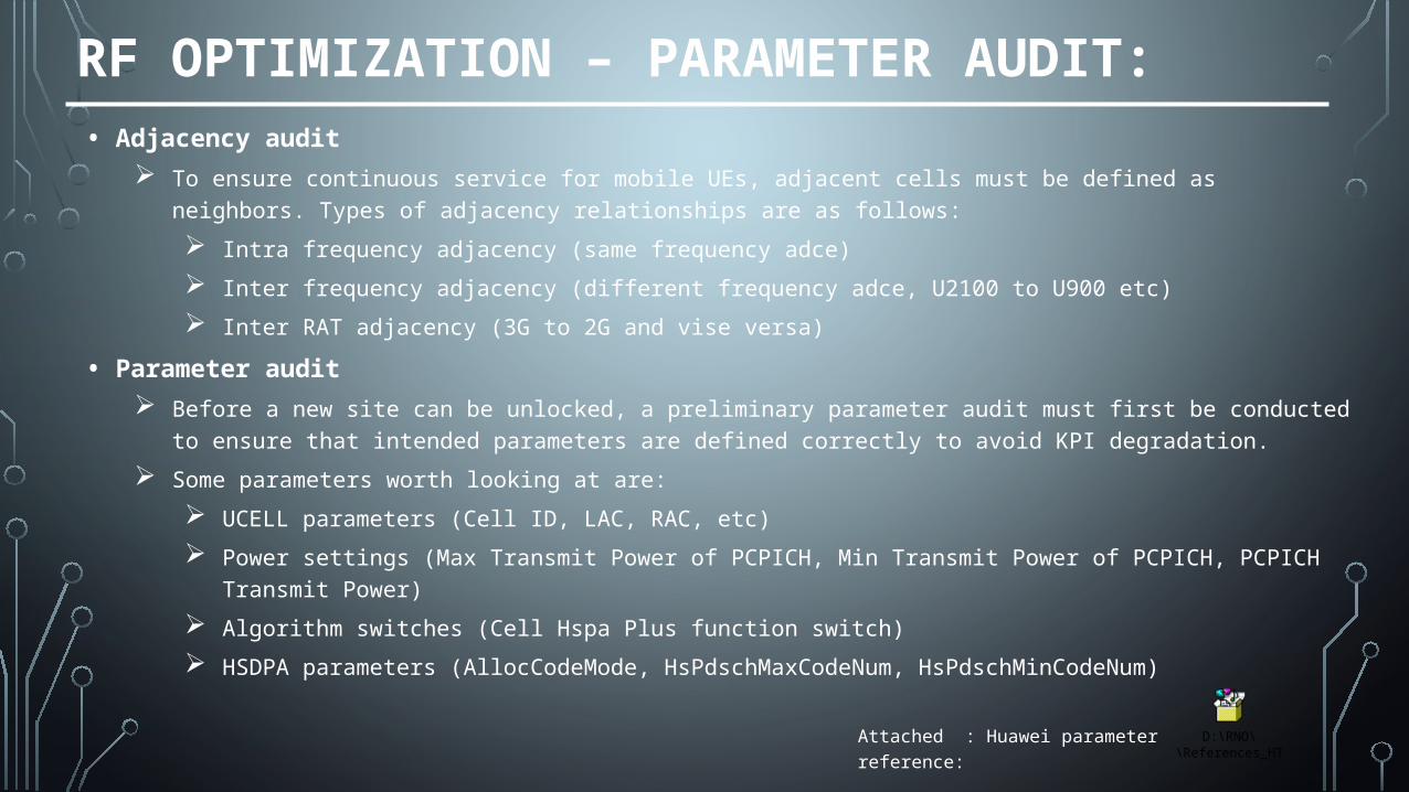
RF OPTIMIZATION – PARAMETER AUDIT:• Adjacency audit
To ensure continuous service for mobile UEs, adjacent cells must be defined as neighbors. Types of adjacency relationships are as follows:
Intra frequency adjacency (same frequency adce)
Inter frequency adjacency (different frequency adce, U2100 to U900 etc)
Inter RAT adjacency (3G to 2G and vise versa)
• Parameter audit Before a new site can be unlocked, a preliminary parameter audit must first be conducted to ensure that intended
parameters are defined correctly to avoid KPI degradation.
Some parameters worth looking at are:
UCELL parameters (Cell ID, LAC, RAC, etc)
Power settings (Max Transmit Power of PCPICH, Min Transmit Power of PCPICH, PCPICH Transmit Power)
Algorithm switches (Cell Hspa Plus function switch)
HSDPA parameters (AllocCodeMode, HsPdschMaxCodeNum, HsPdschMinCodeNum)
D:\RNO\REFERENCES\References_HT\BSC6900\U
Attached : Huawei parameter reference:
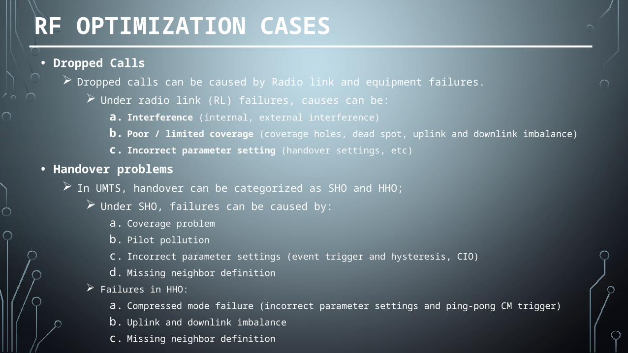
RF OPTIMIZATION CASES• Dropped Calls
Dropped calls can be caused by Radio link and equipment failures.
Under radio link (RL) failures, causes can be:
a. Interference (internal, external interference)
b. Poor / limited coverage (coverage holes, dead spot, uplink and downlink imbalance)
c. Incorrect parameter setting (handover settings, etc)
• Handover problems In UMTS, handover can be categorized as SHO and HHO;
Under SHO, failures can be caused by:
a. Coverage problem
b. Pilot pollution
c. Incorrect parameter settings (event trigger and hysteresis, CIO)
d. Missing neighbor definition
Failures in HHO:
a. Compressed mode failure (incorrect parameter settings and ping-pong CM trigger)
b. Uplink and downlink imbalance
c. Missing neighbor definition
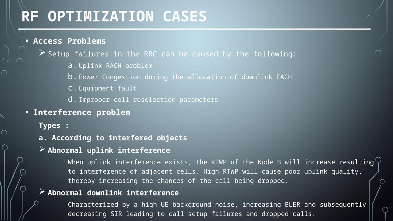
RF OPTIMIZATION CASES
• Access Problems Setup failures in the RRC can be caused by the following:
a. Uplink RACH problem
b. Power Congestion during the allocation of downlink FACH
c. Equipment fault
d. Improper cell reselection parameters
• Interference problem
Types :
a. According to interfered objects
Abnormal uplink interference
When uplink interference exists, the RTWP of the Node B will increase resulting to interference of adjacent cells. High RTWP will cause poor uplink quality, thereby increasing the chances of the call being dropped.
Abnormal downlink interference
Characterized by a high UE background noise, increasing BLER and subsequently decreasing SIR leading to call setup failures and dropped calls.
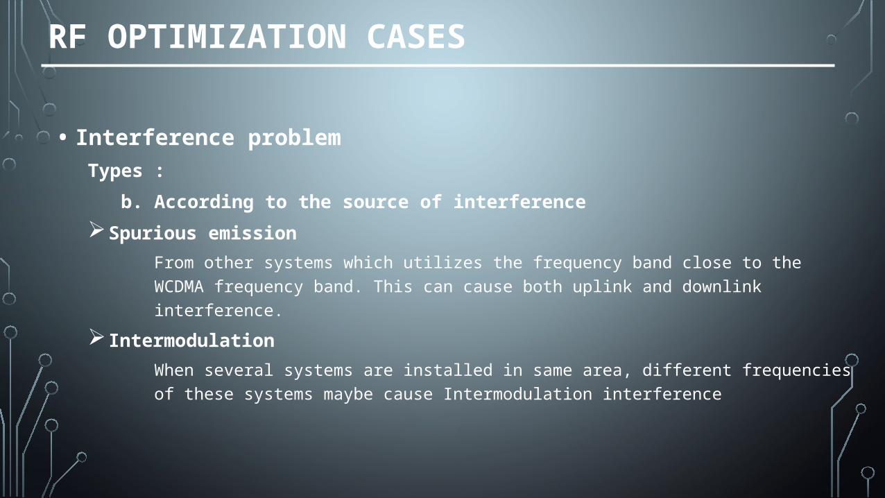
RF OPTIMIZATION CASES
• Interference problemTypes :
b. According to the source of interference
Spurious emission
From other systems which utilizes the frequency band close to the WCDMA frequency band. This can cause both uplink and downlink interference.
Intermodulation
When several systems are installed in same area, different frequencies of these systems maybe cause Intermodulation interference
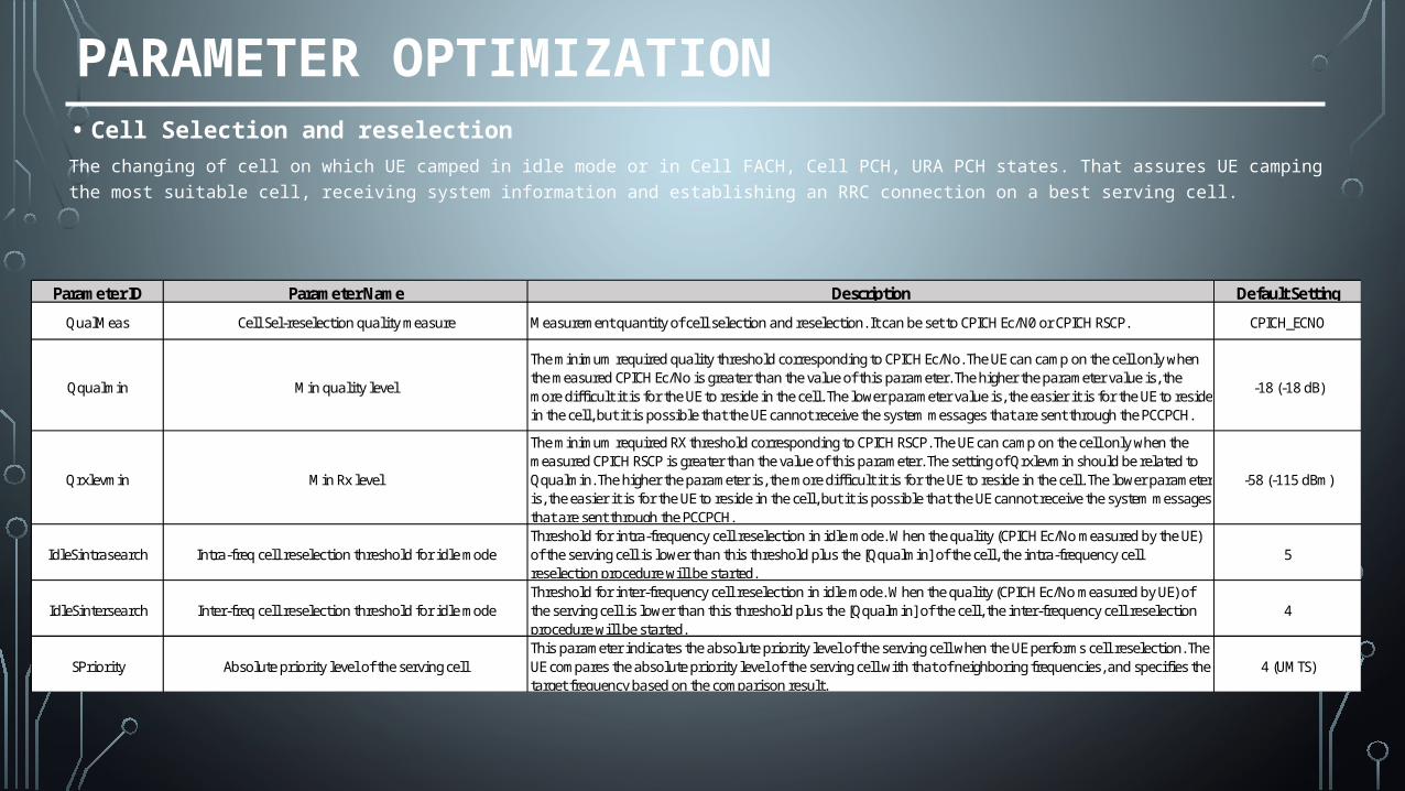
PARAMETER OPTIMIZATION• Cell Selection and reselection
The changing of cell on which UE camped in idle mode or in Cell FACH, Cell PCH, URA PCH states. That assures UE
camping the most suitable cell, receiving system information and establishing an RRC connection on a best serving cell.
Parameter ID Parameter Name Description Default Setting
QualMeas Cell Sel-reselection quality measure Measurement quantity of cell selection and reselection. It can be set to CPICH Ec/N0 or CPICH RSCP. CPICH_ECNO
Qqualmin Min quality level
The minimum required quality threshold corresponding to CPICH Ec/No. The UE can camp on the cell only when the measured CPICH Ec/No is greater than the value of this parameter. The higher the parameter value is, the more difficult it is for the UE to reside in the cell. The lower parameter value is, the easier it is for the UE to reside in the cell, but it is possible that the UE cannot receive the system messages that are sent through the PCCPCH.
-18 (-18 dB)
Qrxlevmin Min Rx level
The minimum required RX threshold corresponding to CPICH RSCP. The UE can camp on the cell only when the measured CPICH RSCP is greater than the value of this parameter. The setting of Qrxlevmin should be related to Qqualmin. The higher the parameter is, the more difficult it is for the UE to reside in the cell. The lower parameter is, the easier it is for the UE to reside in the cell, but it is possible that the UE cannot receive the system messages that are sent through the PCCPCH.
-58 (-115 dBm)
IdleSintrasearch Intra-freq cell reselection threshold for idle modeThreshold for intra-frequency cell reselection in idle mode. When the quality (CPICH Ec/No measured by the UE) of the serving cell is lower than this threshold plus the [Qqualmin] of the cell, the intra-frequency cell reselection procedure will be started.
5
IdleSintersearch Inter-freq cell reselection threshold for idle modeThreshold for inter-frequency cell reselection in idle mode. When the quality (CPICH Ec/No measured by UE) of the serving cell is lower than this threshold plus the [Qqualmin] of the cell, the inter-frequency cell reselection procedure will be started.
4
SPriority Absolute priority level of the serving cellThis parameter indicates the absolute priority level of the serving cell when the UE performs cell reselection. The UE compares the absolute priority level of the serving cell with that of neighboring frequencies, and specifies the target frequency based on the comparison result.
4 (UMTS)
PARAMETER OPTIMIZATION
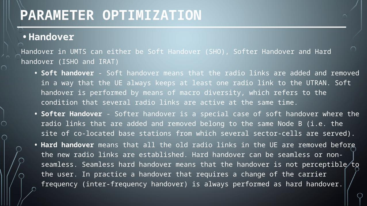
• HandoverHandover in UMTS can either be Soft Handover (SHO), Softer Handover and Hard handover (ISHO
and IRAT)
• Soft handover - Soft handover means that the radio links are added and removed in a way that the UE always keeps at least one radio link to the UTRAN. Soft handover is performed by means of macro diversity, which refers to the condition that several radio links are active at the same time.
• Softer Handover - Softer handover is a special case of soft handover where the radio links that are added and removed belong to the same Node B (i.e. the site of co-located base stations from which several sector-cells are served).
• Hard handover means that all the old radio links in the UE are removed before the new radio links are established. Hard handover can be seamless or non-seamless. Seamless hard handover means that the handover is not perceptible to the user. In practice a handover that requires a change of the carrier frequency (inter-frequency handover) is always performed as hard handover.
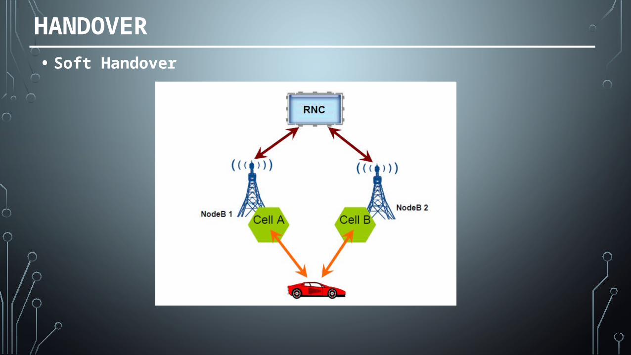
HANDOVER
• Soft Handover
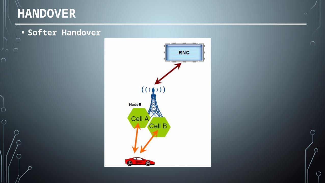
HANDOVER
• Softer Handover
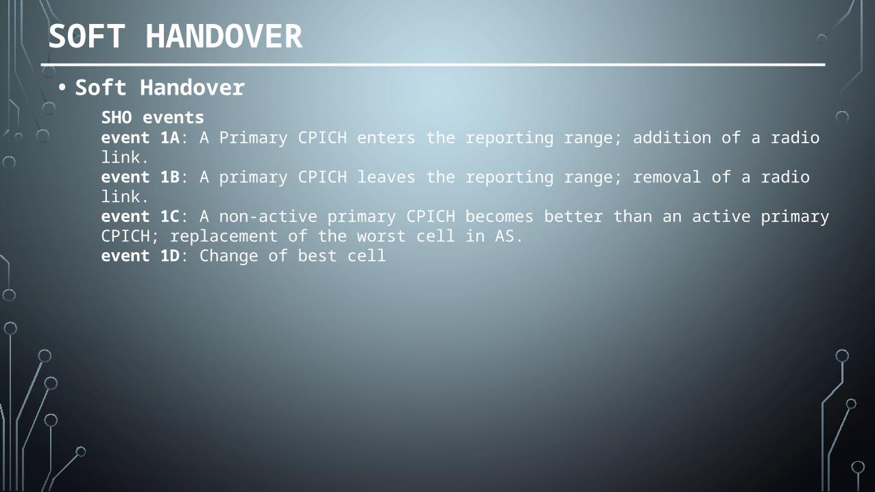
SOFT HANDOVER
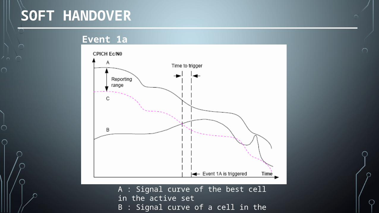
• Soft HandoverSHO eventsevent 1A: A Primary CPICH enters the reporting range; addition of a radio link.event 1B: A primary CPICH leaves the reporting range; removal of a radio link.event 1C: A non-active primary CPICH becomes better than an active primary CPICH; replacement of the worst cell in AS.event 1D: Change of best cell
SOFT HANDOVER
A : Signal curve of the best cell in the active setB : Signal curve of a cell in the monitored setC : The e1a curve
Event 1a
SOFT HANDOVER
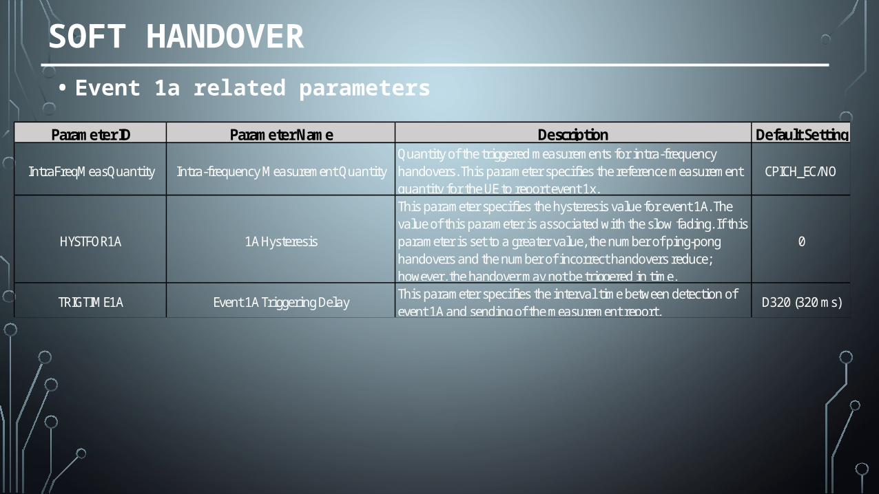
• Event 1a related parameters
Parameter ID Parameter Name Description Default Setting
IntraFreqMeasQuantity Intra-frequency Measurement QuantityQuantity of the triggered measurements for intra-frequency handovers. This parameter specifies the reference measurement quantity for the UE to report event 1x.
CPICH_EC/NO
HYSTFOR1A 1A Hysteresis
This parameter specifies the hysteresis value for event 1A. The value of this parameter is associated with the slow fading. If this parameter is set to a greater value, the number of ping-pong handovers and the number of incorrect handovers reduce; however, the handover may not be triggered in time.
0
TRIGTIME1A Event 1A Triggering DelayThis parameter specifies the interval time between detection of event 1A and sending of the measurement report.
D320 (320 ms)
SOFT HANDOVER
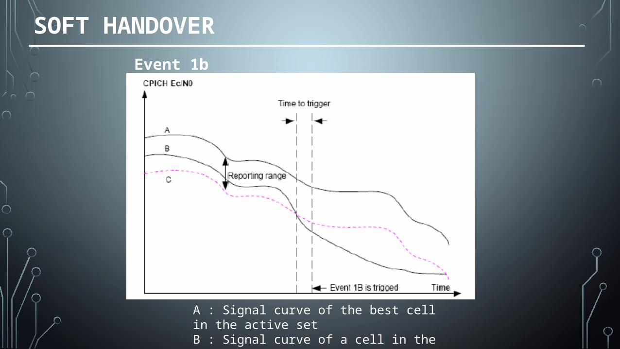
A : Signal curve of the best cell in the active setB : Signal curve of a cell in the monitored setC : The e1b curve
Event 1b

SOFT HANDOVER
Parameter ID Parameter Name Description Default Setting
IntraFreqMeasQuantity Intra-frequency Measurement QuantityQuantity of the triggered measurements for intra-frequency handovers. This parameter specifies the reference measurement quantity for the UE to report event 1x.
CPICH_EC/NO
HYSTFOR1B 1B Hysteresis
This parameter specifies the hysteresis value for event 1B. The value of this parameter is associated with the slow fading, and it can be used to reduce ping-pong handovers and incorrect handovers.
0
TRIGTIME1B Event 1B Triggering DelayThis parameter specifies the interval time between detection of event 1B and sending of the measurement report.
D640 (640ms)
• Event 1b related parameters
SOFT HANDOVER
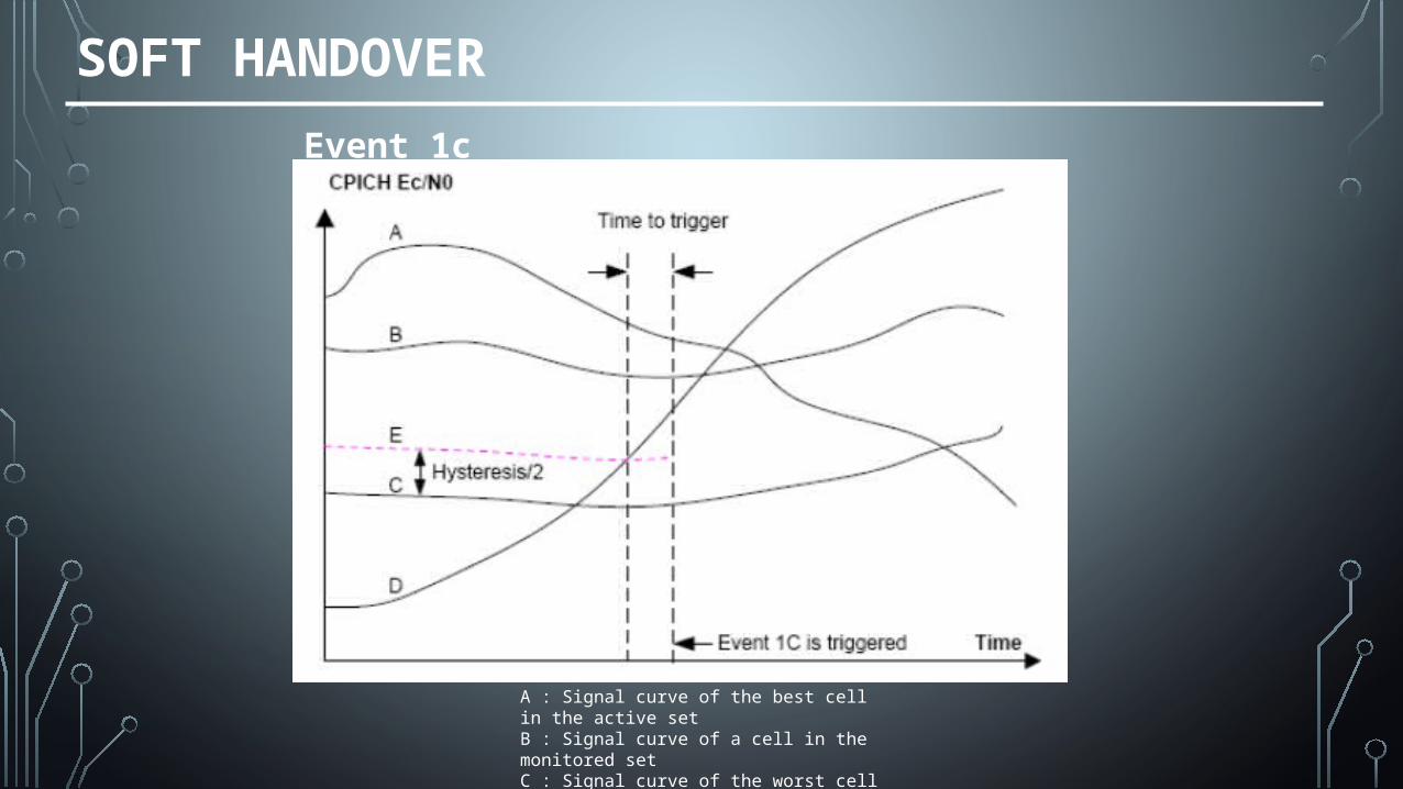
A : Signal curve of the best cell in the active setB : Signal curve of a cell in the monitored setC : Signal curve of the worst cell in the active setD : signal curve of a cell in the monitored setE : The event 1c curve
Event 1c
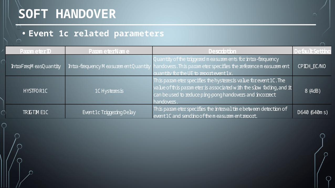
Parameter ID Parameter Name Description Default Setting
IntraFreqMeasQuantity Intra-frequency Measurement QuantityQuantity of the triggered measurements for intra-frequency handovers. This parameter specifies the reference measurement quantity for the UE to report event 1x.
CPICH_EC/NO
HYSTFOR1C 1C Hysteresis
This parameter specifies the hysteresis value for event 1C. The value of this parameter is associated with the slow fading, and it can be used to reduce ping-pong handovers and incorrect handovers.
8 (4dB)
TRIGTIME1C Event 1c Triggering DelayThis parameter specifies the interval time between detection of event 1C and sending of the measurement report.
D640 (640ms)
SOFT HANDOVER
• Event 1c related parameters
SOFT HANDOVER
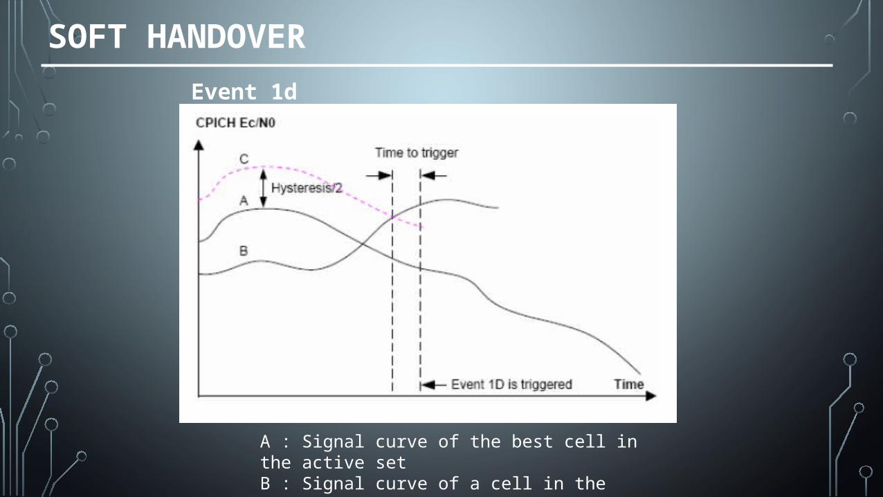
Event 1d
A : Signal curve of the best cell in the active setB : Signal curve of a cell in the active or monitored setC : The e1d curve
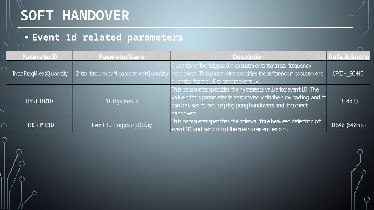
Parameter ID Parameter Name Description Default Setting
IntraFreqMeasQuantity Intra-frequency Measurement QuantityQuantity of the triggered measurements for intra-frequency handovers. This parameter specifies the reference measurement quantity for the UE to report event 1x.
CPICH_EC/NO
HYSTFOR1D 1C Hysteresis
This parameter specifies the hysteresis value for event 1D. The value of this parameter is associated with the slow fading, and it can be used to reduce ping-pong handovers and incorrect handovers.
8 (4dB)
TRIGTIME1D Event 1D Triggering DelayThis parameter specifies the interval time between detection of event 1D and sending of the measurement report.
D640 (640ms)
SOFT HANDOVER
• Event 1d related parameters
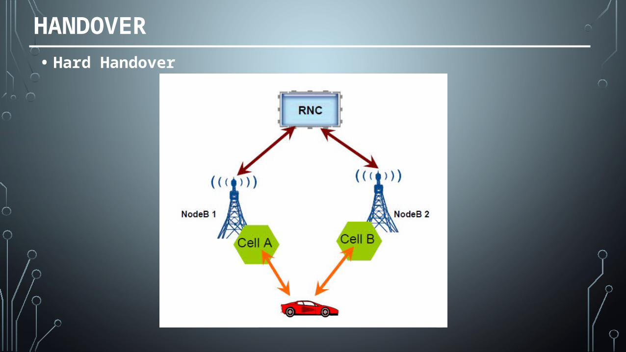
HANDOVER
• Hard Handover
HARD HANDOVER
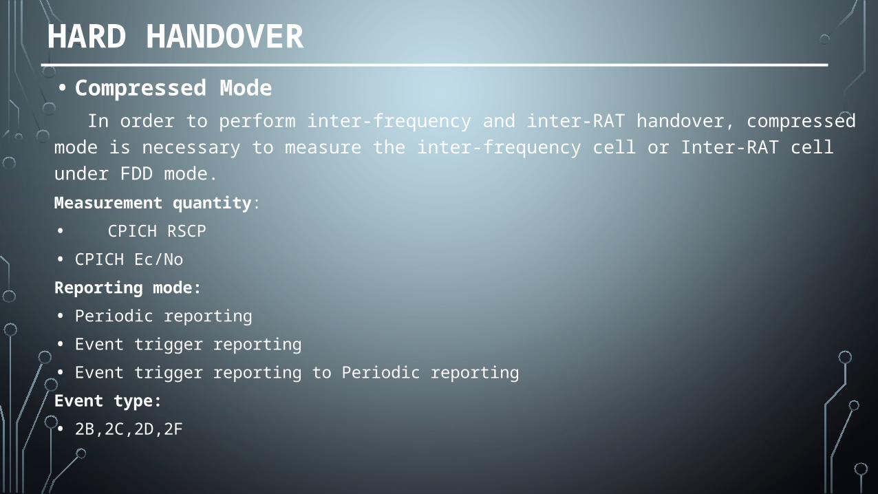
• Compressed ModeIn order to perform inter-frequency and inter-RAT handover, compressed mode is necessary to
measure the inter-frequency cell or Inter-RAT cell under FDD mode.
Measurement quantity:
• CPICH RSCP
• CPICH Ec/No
Reporting mode:
• Periodic reporting
• Event trigger reporting
• Event trigger reporting to Periodic reporting
Event type:
• 2B,2C,2D,2F
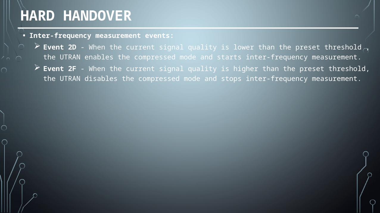
HARD HANDOVER• Inter-frequency measurement events:
Event 2D - When the current signal quality is lower than the preset threshold , the UTRAN enables the compressed mode and starts inter-frequency measurement.
Event 2F - When the current signal quality is higher than the preset threshold, the UTRAN disables the compressed mode and stops inter-frequency measurement.
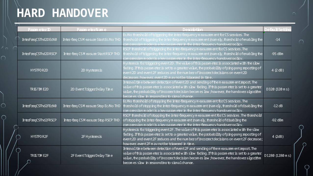
HARD HANDOVERParameter ID Parameter Name Description Default Setting
InterFreqCSThd2DEcN0 Inter-freq CS Measure Start Ec/No THDEc/No threshold of triggering the inter-frequency measurement for CS services. The threshold of triggering the inter-frequency measurement (namely, threshold of enabling the compression mode) is a key parameter in the inter-frequency handover policy.
-14
InterFreqCSThd2DRSCP Inter-freq CS Measure Start RSCP THDRSCP threshold of triggering the inter-frequency measurement for CS services. The threshold of triggering the inter-frequency measurement (namely, threshold of enabling the compression mode) is a key parameter in the inter-frequency handover policy.
-95 dBm
HYSTFOR2D 2D Hysteresis
Hysteresis for triggering event 2D. The value of this parameter is associated with the slow fading. If this parameter is set to a greater value, the probabil ity of ping-pong reporting of event 2D and event 2F reduces and the number of incorrect decisions on event 2D decreases; however, event 2D may not be triggered in time.
4 (2 dB)
TRIGTIME2D 2D Event Trigger Delay Time
Interval time between detection of event 2D and sending of the measurement report. The value of this parameter is associated with slow fading. If this parameter is set to a greater value, the probability of incorrect decision becomes low; however, the handover algorithm becomes slow in responding to signal change.
D320 (320 ms)
InterFreqCSThd2FEcN0 Inter-freq CS Measure Stop Ec/No THDEc/No threshold of stopping the inter-frequency measurement for CS services. The threshold of stopping the inter-frequency measurement (namely, threshold of disabling the compression mode) is a key parameter in the inter-frequency handover policy.
-12 dB
InterFreqCSThd2FRSCP Inter-freq CS Measure Stop RSCP THDRSCP threshold of stopping the inter-frequency measurement for CS services. The threshold of stopping the inter-frequency measurement (namely, threshold of disabling the compression mode) is a key parameter in the inter-frequency handover policy.
-92 dBm
HYSTFOR2F 2F Hysteresis
Hysteresis for triggering event 2F. The value of this parameter is associated with the slow fading. If this parameter is set to a greater value, the probabil ity of ping-pong reporting of event 2D and event 2F reduces and the number of incorrect decisions on event 2F decrease; however, event 2F may not be triggered in time.
4 (2dB)
TRIGTIME2F 2F Event Trigger Delay Time
Interval time between detection of event 2F and sending of the measurement report. The value of this parameter is associated with slow fading. If this parameter is set to a greater value, the probability of incorrect decision becomes low; however, the handover algorithm becomes slow in responding to signal change.
D1280 (1280 ms)
END
QUESTIONS?