Embed Size (px)
Citation preview

DCP Manual Version 1.14
Little Sensors, Big Ideas® www.microstrain.com
3DM-GX3®-25 Data Communications Protocol
Single Byte Command API
Firmware Versions 0.4.14, 1.1.27, 1.1.30 and higher

MicroStrain, Inc.
2
©2010 by MicroStrain, Inc.
459 Hurricane Lane
Williston, VT 05495
United States of America
Phone: 802-862-6629
Fax: 802-863-4093
www.microstrain.com
REVISED: Feb 10, 2011
MicroStrain, Inc.
3
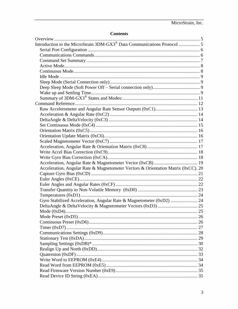
Contents Overview ............................................................................................................................. 5
Introduction to the MicroStrain 3DM-GX3® Data Communications Protocol .................. 5
Serial Port Configuration ................................................................................................ 6
Communications Commands .......................................................................................... 6
Command Set Summary ................................................................................................. 7
Active Mode.................................................................................................................... 8
Continuous Mode ............................................................................................................ 8
Idle Mode ........................................................................................................................ 9
Sleep Mode (Serial Connection only) ............................................................................. 9
Deep Sleep Mode (Soft Power Off – Serial connection only) ........................................ 9
Wake up and Settling Time............................................................................................. 9
Summary of 3DM-GX3®
States and Modes: ................................................................ 11
Command Reference ......................................................................................................... 12
Raw Accelerometer and Angular Rate Sensor Outputs (0xC1) .................................... 13
Acceleration & Angular Rate (0xC2) ........................................................................... 14
DeltaAngle & DeltaVelocity (0xC3) ............................................................................ 14
Set Continuous Mode (0xC4) ....................................................................................... 15
Orientation Matrix (0xC5) ............................................................................................ 16
Orientation Update Matrix (0xC6) ................................................................................ 16
Scaled Magnetometer Vector (0xC7) ........................................................................... 17
Acceleration, Angular Rate & Orientation Matrix (0xC8) ........................................... 17
Write Accel Bias Correction (0xC9)............................................................................. 18
Write Gyro Bias Correction (0xCA) ............................................................................. 18
Acceleration, Angular Rate & Magnetometer Vector (0xCB) ..................................... 19
Acceleration, Angular Rate & Magnetometer Vectors & Orientation Matrix (0xCC) . 20
Capture Gyro Bias (0xCD) ........................................................................................... 21
Euler Angles (0xCE) ..................................................................................................... 22
Euler Angles and Angular Rates (0xCF) ...................................................................... 22
Transfer Quantity to Non-Volatile Memory (0xD0) ................................................... 23
Temperatures (0xD1) .................................................................................................... 24
Gyro Stabilized Acceleration, Angular Rate & Magnetometer (0xD2) ....................... 24
DeltaAngle & DeltaVelocity & Magnetometer Vectors (0xD3) .................................. 25
Mode (0xD4) ................................................................................................................. 25
Mode Preset (0xD5) ...................................................................................................... 26
Continuous Preset (0xD6) ............................................................................................. 26
Timer (0xD7) ................................................................................................................ 27
Communications Settings (0xD9) ................................................................................. 28
Stationary Test (0xDA) ................................................................................................. 29
Sampling Settings (0xDB)* .......................................................................................... 30
Realign Up and North (0xDD) ...................................................................................... 32
Quaternion (0xDF) ........................................................................................................ 33
Write Word to EEPROM (0xE4) .................................................................................. 34
Read Word from EEPROM (0xE5) .............................................................................. 34
Read Firmware Version Number (0xE9) ...................................................................... 35
Read Device ID String (0xEA) ..................................................................................... 35
MicroStrain, Inc.
4
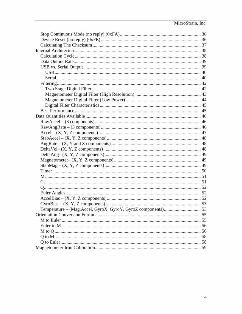
Stop Continuous Mode (no reply) (0xFA) .................................................................... 36
Device Reset (no reply) (0xFE) .................................................................................... 36
Calculating The Checksum ........................................................................................... 37
Internal Architecture ......................................................................................................... 38
Calculation Cycle .......................................................................................................... 38
Data Output Rate........................................................................................................... 39
USB vs. Serial Output ................................................................................................... 39
USB ........................................................................................................................... 40
Serial ......................................................................................................................... 40
Filtering ......................................................................................................................... 42
Two Stage Digital Filter............................................................................................ 42
Magnetometer Digital Filter (High Resolution) ....................................................... 43
Magnetometer Digital Filter (Low Power) ............................................................... 44
Digital Filter Characteristics ..................................................................................... 45
Best Performance .......................................................................................................... 45
Data Quantities Available ................................................................................................. 46
RawAccel – (3 components) ......................................................................................... 46
RawAngRate – (3 components) .................................................................................... 46
Accel – (X, Y, Z components) ...................................................................................... 47
StabAccel – (X, Y, Z components) ............................................................................... 48
AngRate – (X, Y and Z components) ........................................................................... 48
DeltaVel– (X, Y, Z components) .................................................................................. 48
DeltaAng– (X, Y, Z components) ................................................................................. 49
Magnetometer– (X, Y, Z components) ......................................................................... 49
StabMag – (X, Y, Z components) ................................................................................. 49
Timer ............................................................................................................................. 50
M ................................................................................................................................... 51
C .................................................................................................................................... 51
Q .................................................................................................................................... 52
Euler Angles.................................................................................................................. 52
AccelBias – (X, Y, Z components) ............................................................................... 52
GyroBias – (X, Y, Z components) ................................................................................ 53
Temperature – (Mag,Accel, GyroX, GyroY, GyroZ components) ............................... 53
Orientation Conversion Formulas ..................................................................................... 55
M to Euler ..................................................................................................................... 55
Euler to M ..................................................................................................................... 56
M to Q ........................................................................................................................... 56
Q to M ........................................................................................................................... 58
Q to Euler ...................................................................................................................... 58
Magnetometer Iron Calibration ......................................................................................... 59

MicroStrain, Inc.
5
Overview The 3DM-GX3
® utilizes MicroStrain’s fourth generation orientation sensor core and
offers more performance and features than previous models including:
32-bit low power high performance processor
USB and serial UART host interface
17 bit resolution on Gyros, Accelerometers, and Magnetometers
Full 1kHz Coning and Sculling integration
Cascaded adjustable FIR filters
Data rates of up to 1000Hz
Smallest and lightest full function 6-DOF orientation sensor
Fully calibrated and temperature compensated outputs
This document describes how to communicate with the MicroStrain 3DM-GX3® Attitude
Heading Reference System (AHRS). The communications interface is compatible with
our Inertia-Link® and 3DM-GX2
® devices but has expanded functionality.
This version of the Data Communications Protocol includes documentation of the new
features supported starting with version 1.1.27 of the firmware. If you are upgrading
from 0.4.14 of the firmware review the important additions and changes flagged with
asterisks in the Command Set Summary and highlighted in green in the document.
Introduction to the MicroStrain 3DM-GX3® Data
Communications Protocol The 3DM-GX3
® Data Communications Protocol is a set of serial commands and
responses designed specifically for MicroStrain’s orientation sensors. For the most part,
the communications protocol consists of simple single byte binary commands with fixed
length binary data records as replies. Most replies include an “echo” byte (echo of the
command byte) and a checksum to do simple data integrity checks.
The standard serial protocol is described below in Communications Commands.
Note: This document is the reference for the “Single Byte” command protocol. This
protocol was introduced with the 3DM-GX1 and 3DM-GX2 series of devices and
continued and expanded with the 3DM-GX3-25. Starting with the 3DM-GX3-35, a new
packet protocol has been introduced and referred to as the “MIP Packet Protocol”. For
information on the new protocol, refer to the “3DM-GX3-35 Data Communications
Protocol”. All 3DM-GX3 devices will eventually move to this protocol, however the
“single byte” protocol will continue to be supported on the 3DM-GX3-25 AHRS module.
MicroStrain, Inc.
6
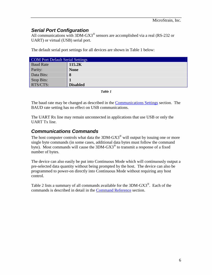
Serial Port Configuration All communications with 3DM-GX3
® sensors are accomplished via a real (RS-232 or
UART) or virtual (USB) serial port.
The default serial port settings for all devices are shown in Table 1 below:
COM Port Default Serial Settings
Baud Rate 115.2K
Parity: None
Data Bits: 8
Stop Bits: 1
RTS/CTS: Disabled
Table 1
The baud rate may be changed as described in the Communications Settings section. The
BAUD rate setting has no effect on USB communications.
The UART Rx line may remain unconnected in applications that use USB or only the
UART Tx line.
Communications Commands
The host computer controls what data the 3DM-GX3® will output by issuing one or more
single byte commands (in some cases, additional data bytes must follow the command
byte). Most commands will cause the 3DM-GX3® to transmit a response of a fixed
number of bytes.
The device can also easily be put into Continuous Mode which will continuously output a
pre-selected data quantity without being prompted by the host. The device can also be
programmed to power-on directly into Continuous Mode without requiring any host
control.
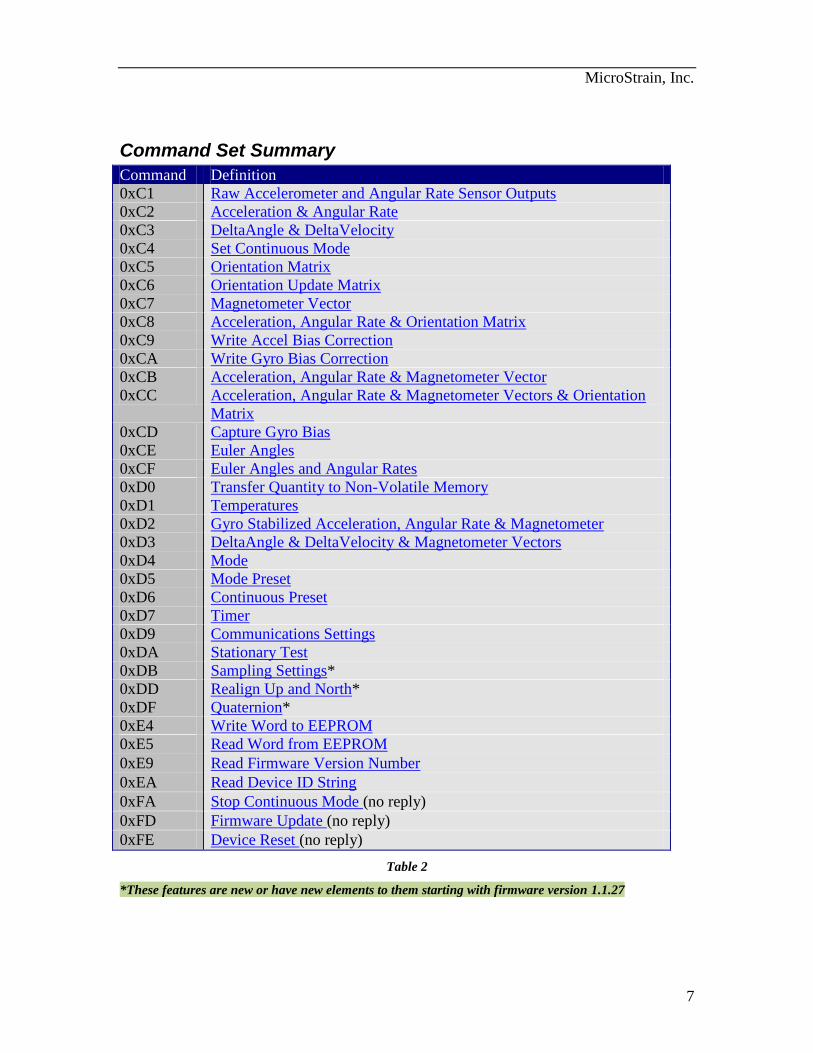
Table 2 lists a summary of all commands available for the 3DM-GX3®. Each of the
commands is described in detail in the Command Reference section.
MicroStrain, Inc.
7
Command Set Summary
Command Definition
0xC1 Raw Accelerometer and Angular Rate Sensor Outputs
0xC2 Acceleration & Angular Rate
0xC3 DeltaAngle & DeltaVelocity
0xC4 Set Continuous Mode
0xC5 Orientation Matrix
0xC6 Orientation Update Matrix
0xC7 Magnetometer Vector
0xC8 Acceleration, Angular Rate & Orientation Matrix
0xC9 Write Accel Bias Correction
0xCA Write Gyro Bias Correction
0xCB Acceleration, Angular Rate & Magnetometer Vector
0xCC Acceleration, Angular Rate & Magnetometer Vectors & Orientation
Matrix
0xCD Capture Gyro Bias
0xCE Euler Angles
0xCF Euler Angles and Angular Rates
0xD0 Transfer Quantity to Non-Volatile Memory
0xD1 Temperatures
0xD2 Gyro Stabilized Acceleration, Angular Rate & Magnetometer
0xD3 DeltaAngle & DeltaVelocity & Magnetometer Vectors
0xD4 Mode
0xD5 Mode Preset
0xD6 Continuous Preset
0xD7 Timer
0xD9 Communications Settings
0xDA Stationary Test
0xDB Sampling Settings*
0xDD Realign Up and North*
0xDF Quaternion*
0xE4 Write Word to EEPROM
0xE5 Read Word from EEPROM
0xE9 Read Firmware Version Number
0xEA Read Device ID String
0xFA Stop Continuous Mode (no reply)
0xFD Firmware Update (no reply)
0xFE Device Reset (no reply)
Table 2
*These features are new or have new elements to them starting with firmware version 1.1.27
MicroStrain, Inc.
8
Device States and Modes
The 3DM-GX3® operates in one of two states: Awake or Sleep. In the awake state, there
are three possible modes of operation Continuous, Active, or Idle. In the sleep state
there are two possible modes: Sleep, Deep Sleep. Note that the Sleep and Deep Sleep
modes are only available when the unit is connected to the host via the Serial port
(LVTTL UART on the OEM version). The Sleep state is not available when connected
via USB.
The 3DM-GX3® can transition from the sleep state to the awake state in one of two ways:
1. Power On
2. Sending any character to the serial port.
When the 3DM-GX3®
goes into the awake state, it will go into the mode pre-selected by
a Mode Preset command.
The 3DM-GX3® can transition from the awake state to the sleep state via a UART Mode
command.
Active Mode
In active mode, the 3DM-GX3® has all sensors powered on and is performing continuous
sampling and data conditioning. The communications channel is open and the 3DM-
GX3® can respond to any configuration, status, or data command. The host may issue any
command at any time. The sensor will not output unsolicited data records. The 3DM-
GX3® will respond to data commands by outputting the corresponding data record.
Multiple commands issued by the host will be buffered on-board the device, with one
being processed at the completion of each successive sampling cycle.
Continuous Mode
In continuous mode, the 3DM-GX3® will output a data record continuously with no
further action by the host. The data record output corresponds to the preset data
command set by the last call to Continuous Preset. The host computer must be capable of
buffering and interpreting the data stream at sufficient speed to prevent loss of data. For
information on the data rate in the continuous mode, see the Calculation Cycle, and Data
Output Rate section.
Once continuous mode is set, it will remain in effect until it is terminated by issuing a
different Mode command or the power to the device is interrupted.
An alternate single byte command, Set Continuous Mode, can be used to start continuous
mode. This command does not change the continuous preset value.
MicroStrain, Inc.
9
An alternate single byte termination command, Stop Continuous Mode, may be used to
stop the continuous mode and put the sensor into active mode. The benefit of this
command is that it does not generate a response packet. This can be advantageous where
the introduction of a response packet in the middle of a data stream can cause a parser to
get out of sync with the stream.
Although the 3DM-GX3® will still act on and respond to all other commands while in
continuous mode, it is better to change to active or idle mode before doing configuration
commands. This makes it easier for the host to parse the incoming stream of response
packets.
Note: From the factory, the continuous preset value is 0 which results in no action when
changing to continuous mode with the Mode command. The continuous preset value
must be set to a valid data command for continuous mode to be activated.
Note: When using the mode command to set the mode to continuous, the 3DM-GX3®
will
send the mode command reply packet before entering into continuous mode. In other
words, you will receive the reply packet followed by the first data packet specified by the
Continuous Preset command.
Idle Mode
The idle mode is the same as the active mode in that the 3DM-GX3® will respond to any
configuration, status, or data command. However, in the idle mode, the sensors are
turned off and data commands return invalid sensor data. For all calculated floating point
data, the values returned will be NaN. For raw data, the values will just be undetermined.
This mode is useful when doing configuration on a battery powered system and you need
to minimize the power consumption. Idle mode draws approximately one half of the
current compared to active mode.
Sleep Mode (Serial Connection only)
The sleep mode is a lower power mode than idle mode. The difference is that the
processor and clocks are turned off as well as the sensors.
Deep Sleep Mode (Soft Power Off – Serial connection only)
The deep sleep mode is the lowest power mode other than fully turning the device off.
This mode may be used as an alternative to having a physical power off circuit at very
low power cost.
Wake up and Settling Time
The 3DM-GX3® is put into a sleep state by calling the Mode command with one of the
sleep modes as a parameter. When the 3DM-GX3® is awakened, it goes into one of the
awake state modes depending on what was preset using the Mode Preset command.

MicroStrain, Inc.
10
The latency between a wakeup event (Power on or UART command) and the first valid
data available from the 3DM-GX3® is largely determined by the sensor power settling
time and filter initialization time. The approximate wake time to valid data (in seconds)
can be computed by the formula:
1000/2053.0 MTwake
Equation 1
where M is the filter width (see Filtering).
MicroStrain, Inc.
11
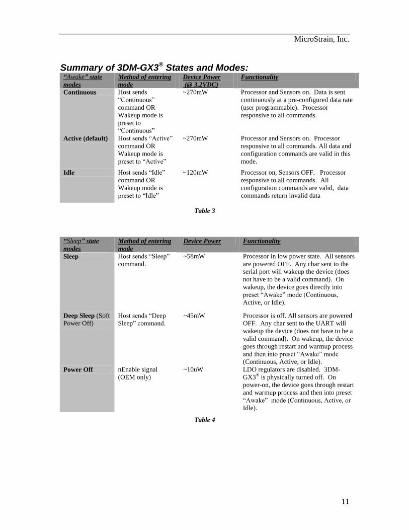
Summary of 3DM-GX3® States and Modes: “Awake” state
modes
Method of entering
mode
Device Power
(@ 3.2VDC)
Functionality
Continuous Host sends
“Continuous”
command OR
Wakeup mode is
preset to
“Continuous”
~270mW Processor and Sensors on. Data is sent
continuously at a pre-configured data rate
(user programmable). Processor
responsive to all commands.
Active (default) Host sends “Active”
command OR
Wakeup mode is
preset to “Active”
~270mW Processor and Sensors on. Processor
responsive to all commands. All data and
configuration commands are valid in this
mode.
Idle Host sends “Idle”
command OR
Wakeup mode is
preset to “Idle”
~120mW Processor on, Sensors OFF. Processor
responsive to all commands. All
configuration commands are valid, data
commands return invalid data
Table 3
“Sleep” state
modes
Method of entering
mode
Device Power Functionality
Sleep Host sends “Sleep”
command.
~58mW Processor in low power state. All sensors
are powered OFF. Any char sent to the
serial port will wakeup the device (does
not have to be a valid command). On
wakeup, the device goes directly into
preset “Awake” mode (Continuous,
Active, or Idle).
Deep Sleep (Soft
Power Off)
Host sends “Deep
Sleep” command.
~45mW Processor is off. All sensors are powered
OFF. Any char sent to the UART will
wakeup the device (does not have to be a
valid command). On wakeup, the device
goes through restart and warmup process
and then into preset “Awake” mode
(Continuous, Active, or Idle).
Power Off nEnable signal
(OEM only)
~10uW LDO regulators are disabled. 3DM-
GX3® is physically turned off. On
power-on, the device goes through restart
and warmup process and then into preset
“Awake” mode (Continuous, Active, or
Idle).
Table 4
MicroStrain, Inc.
12
Command Reference All commands, at minimum, consist of a command byte. Several commands require
additional data bytes following the command byte to fully define the action to be taken.
The number of bytes in a response varies from command to command, but the response
for a given command is always a fixed length. There are no variable length responses.
The response to most commands begins with a header byte (which has the same value as
the corresponding command byte), and ends with a 16 bit checksum. The intervening
bytes contain the data requested.
The 16 bit checksum is equal to the sum of all preceding bytes with rollover from 65535
to 0 (see Calculating The Checksum). It is important that the host software evaluate the
checksum from all responses to prevent errors due to out-of-sync data streams.
Some commands that change settings or memory values contain a confirmation byte
sequence as part of the command data. This is to prevent accidental changes in settings
from spurious serial input. If the confirmation sequence is invalid, a 3 byte error reply
will be sent instead of the expected data reply. This reply consists of the following bytes:
0x21 0x00 0x21. The first byte is the error command byte. The second and third bytes
are the checksum, which is always 0x00 0x21.
On commands that change settings, range checking is employed and any value that is out
of range will be brought into range. The new in-range value will be used for the setting
and be returned in the reply. In cases where only a certain set of values are allowed, if
the value is not part of the allowed set, it is ignored and the current value of the setting
remains in force and is returned in the reply. Note that the reply always reflects the
actual settings of the device.
All multi-byte quantities are transmitted in Big Endian order (MSB first, LSB last) by
default. All data quantities are expressed as floating point values except where noted.
Floating point values are 32 bit (4 bytes), and conform to the IEEE-754 format.
The data quantities returned for Temperature and certain values used in Write Word To
EEPROM and Read Word From EEPROM use 16 bit unsigned integers constructed from
2 bytes. The first byte is referred to as the MSB (most significant byte) and the second
byte is referred to as the LSB (least significant byte). Values are constructed using the
following formula: (256 * MSB) + LSB = value.
MicroStrain, Inc.
13
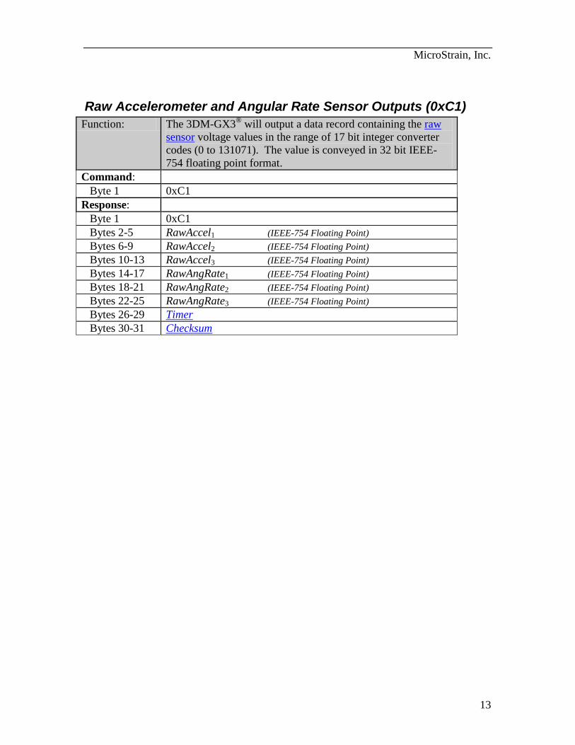
Raw Accelerometer and Angular Rate Sensor Outputs (0xC1)
Function: The 3DM-GX3®
will output a data record containing the raw
sensor voltage values in the range of 17 bit integer converter
codes (0 to 131071). The value is conveyed in 32 bit IEEE-
754 floating point format.
Command:
Byte 1 0xC1
Response:
Byte 1 0xC1
Bytes 2-5 RawAccel1 (IEEE-754 Floating Point)
Bytes 6-9 RawAccel2 (IEEE-754 Floating Point)
Bytes 10-13 RawAccel3 (IEEE-754 Floating Point)
Bytes 14-17 RawAngRate1 (IEEE-754 Floating Point)
Bytes 18-21 RawAngRate2 (IEEE-754 Floating Point)
Bytes 22-25 RawAngRate3 (IEEE-754 Floating Point)
Bytes 26-29 Timer
Bytes 30-31 Checksum
MicroStrain, Inc.
14
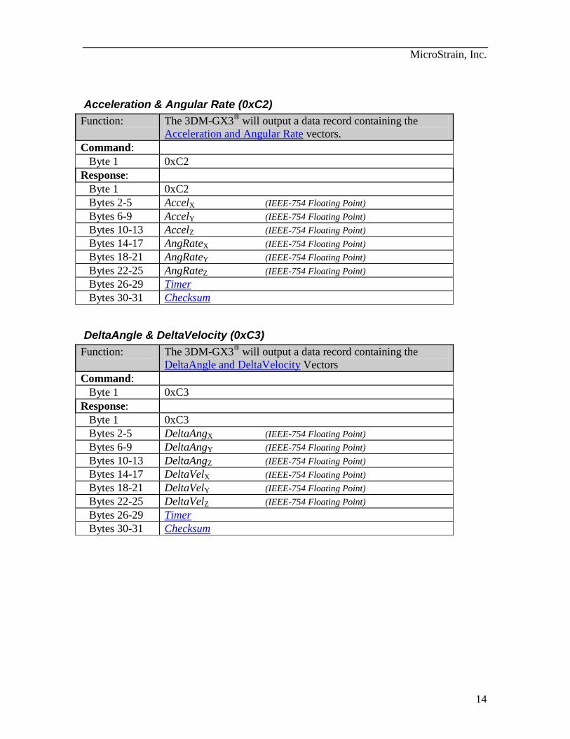
Acceleration & Angular Rate (0xC2)
Function: The 3DM-GX3®
will output a data record containing the
Acceleration and Angular Rate vectors.
Command:
Byte 1 0xC2
Response:
Byte 1 0xC2
Bytes 2-5 AccelX (IEEE-754 Floating Point)
Bytes 6-9 AccelY (IEEE-754 Floating Point)
Bytes 10-13 AccelZ (IEEE-754 Floating Point)
Bytes 14-17 AngRateX (IEEE-754 Floating Point)
Bytes 18-21 AngRateY (IEEE-754 Floating Point)
Bytes 22-25 AngRateZ (IEEE-754 Floating Point)
Bytes 26-29 Timer
Bytes 30-31 Checksum
DeltaAngle & DeltaVelocity (0xC3)
Function: The 3DM-GX3®
will output a data record containing the
DeltaAngle and DeltaVelocity Vectors
Command:
Byte 1 0xC3
Response:
Byte 1 0xC3
Bytes 2-5 DeltaAngX (IEEE-754 Floating Point)
Bytes 6-9 DeltaAngY (IEEE-754 Floating Point)
Bytes 10-13 DeltaAngZ (IEEE-754 Floating Point)
Bytes 14-17 DeltaVelX (IEEE-754 Floating Point)
Bytes 18-21 DeltaVelY (IEEE-754 Floating Point)
Bytes 22-25 DeltaVelZ (IEEE-754 Floating Point)
Bytes 26-29 Timer
Bytes 30-31 Checksum

MicroStrain, Inc.
15
Set Continuous Mode (0xC4)
Function: The 3DM-GX3®
will begin continuous output mode. The
“Continuous Command Byte” determines which data record is
generated. This should be set equal to the Command Byte
corresponding to the desired data record. To stop continuous
mode, set the Continuous Command Byte to 0 or use the Stop
Continuous Mode command.
Note: The continuous mode set using this command will
remain in effect until the device is de-powered. On subsequent
power-up, the device will revert to its original state. To store
a continuous mode setting that will persist through power-
cycles, see the Mode Preset and Continuous Preset commands.
Command:
Byte 1 0xC4
Byte 2 0xC1 (Confirms user intent)
Byte 3 0x29 (Confirms user intent)
Byte 4 Continuous Command Byte (8 bit unsigned integer)
Response:
Byte 1 0xC4
Byte 2 Continuous Command Byte
Bytes 3-6 Timer
Bytes 7-8 Checksum
MicroStrain, Inc.
16
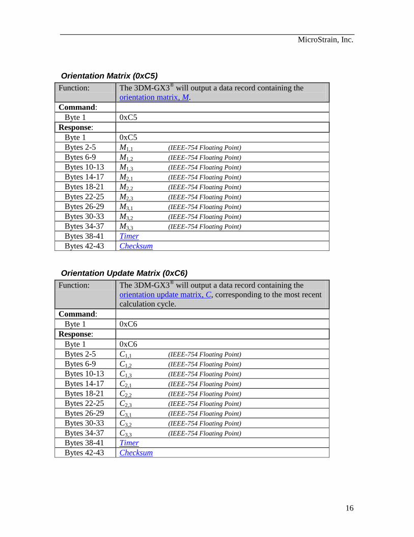
Orientation Matrix (0xC5)
Function: The 3DM-GX3®
will output a data record containing the
orientation matrix, M.
Command:
Byte 1 0xC5
Response:
Byte 1 0xC5
Bytes 2-5 M1,1 (IEEE-754 Floating Point)
Bytes 6-9 M1,2 (IEEE-754 Floating Point)
Bytes 10-13 M1,3 (IEEE-754 Floating Point)
Bytes 14-17 M2,1 (IEEE-754 Floating Point)
Bytes 18-21 M2,2 (IEEE-754 Floating Point)
Bytes 22-25 M2,3 (IEEE-754 Floating Point)
Bytes 26-29 M3,1 (IEEE-754 Floating Point)
Bytes 30-33 M3,2 (IEEE-754 Floating Point)
Bytes 34-37 M3,3 (IEEE-754 Floating Point)
Bytes 38-41 Timer
Bytes 42-43 Checksum
Orientation Update Matrix (0xC6)
Function: The 3DM-GX3®
will output a data record containing the
orientation update matrix, C, corresponding to the most recent
calculation cycle.
Command:
Byte 1 0xC6
Response:
Byte 1 0xC6
Bytes 2-5 C1,1 (IEEE-754 Floating Point)
Bytes 6-9 C1,2 (IEEE-754 Floating Point)
Bytes 10-13 C1,3 (IEEE-754 Floating Point)
Bytes 14-17 C2,1 (IEEE-754 Floating Point)
Bytes 18-21 C2,2 (IEEE-754 Floating Point)
Bytes 22-25 C2,3 (IEEE-754 Floating Point)
Bytes 26-29 C3,1 (IEEE-754 Floating Point)
Bytes 30-33 C3,2 (IEEE-754 Floating Point)
Bytes 34-37 C3,3 (IEEE-754 Floating Point)
Bytes 38-41 Timer
Bytes 42-43 Checksum
MicroStrain, Inc.
17
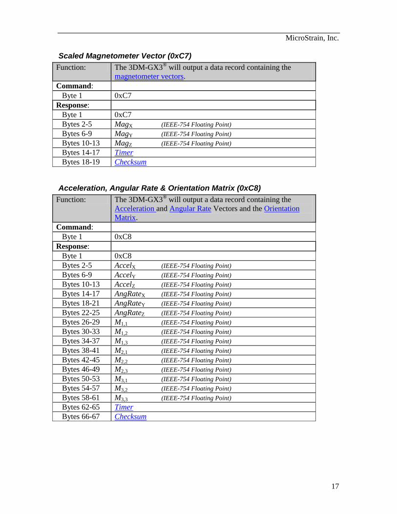
Scaled Magnetometer Vector (0xC7)
Function: The 3DM-GX3®
will output a data record containing the
magnetometer vectors.
Command:
Byte 1 0xC7
Response:
Byte 1 0xC7
Bytes 2-5 MagX (IEEE-754 Floating Point)
Bytes 6-9 MagY (IEEE-754 Floating Point)
Bytes 10-13 MagZ (IEEE-754 Floating Point)
Bytes 14-17 Timer
Bytes 18-19 Checksum
Acceleration, Angular Rate & Orientation Matrix (0xC8)
Function: The 3DM-GX3®
will output a data record containing the
Acceleration and Angular Rate Vectors and the Orientation
Matrix.
Command:
Byte 1 0xC8
Response:
Byte 1 0xC8
Bytes 2-5 AccelX (IEEE-754 Floating Point)
Bytes 6-9 AccelY (IEEE-754 Floating Point)
Bytes 10-13 AccelZ (IEEE-754 Floating Point)
Bytes 14-17 AngRateX (IEEE-754 Floating Point)
Bytes 18-21 AngRateY (IEEE-754 Floating Point)
Bytes 22-25 AngRateZ (IEEE-754 Floating Point)
Bytes 26-29 M1,1 (IEEE-754 Floating Point)
Bytes 30-33 M1,2 (IEEE-754 Floating Point)
Bytes 34-37 M1,3 (IEEE-754 Floating Point)
Bytes 38-41 M2,1 (IEEE-754 Floating Point)
Bytes 42-45 M2,2 (IEEE-754 Floating Point)
Bytes 46-49 M2,3 (IEEE-754 Floating Point)
Bytes 50-53 M3,1 (IEEE-754 Floating Point)
Bytes 54-57 M3,2 (IEEE-754 Floating Point)
Bytes 58-61 M3,3 (IEEE-754 Floating Point)
Bytes 62-65 Timer
Bytes 66-67 Checksum
MicroStrain, Inc.
18
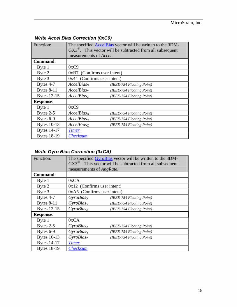
Write Accel Bias Correction (0xC9)
Function: The specified AccelBias vector will be written to the 3DM-
GX3®. This vector will be subtracted from all subsequent
measurements of Accel.
Command:
Byte 1 0xC9
Byte 2 0xB7 (Confirms user intent)
Byte 3 0x44 (Confirms user intent)
Bytes 4-7 AccelBiasX (IEEE-754 Floating Point)
Bytes 8-11 AccelBiasY (IEEE-754 Floating Point)
Bytes 12-15 AccelBiasZ (IEEE-754 Floating Point)
Response:
Byte 1 0xC9
Bytes 2-5 AccelBiasX (IEEE-754 Floating Point)
Bytes 6-9 AccelBiasY (IEEE-754 Floating Point)
Bytes 10-13 AccelBiasZ (IEEE-754 Floating Point)
Bytes 14-17 Timer
Bytes 18-19 Checksum
Write Gyro Bias Correction (0xCA)
Function: The specified GyroBias vector will be written to the 3DM-
GX3®. This vector will be subtracted from all subsequent
measurements of AngRate.
Command:
Byte 1 0xCA
Byte 2 0x12 (Confirms user intent)
Byte 3 0xA5 (Confirms user intent)
Bytes 4-7 GyroBiasX (IEEE-754 Floating Point)
Bytes 8-11 GyroBiasY (IEEE-754 Floating Point)
Bytes 12-15 GyroBiasZ (IEEE-754 Floating Point)
Response:
Byte 1 0xCA
Bytes 2-5 GyroBiasX (IEEE-754 Floating Point)
Bytes 6-9 GyroBiasY (IEEE-754 Floating Point)
Bytes 10-13 GyroBiasZ (IEEE-754 Floating Point)
Bytes 14-17 Timer
Bytes 18-19 Checksum
MicroStrain, Inc.
19
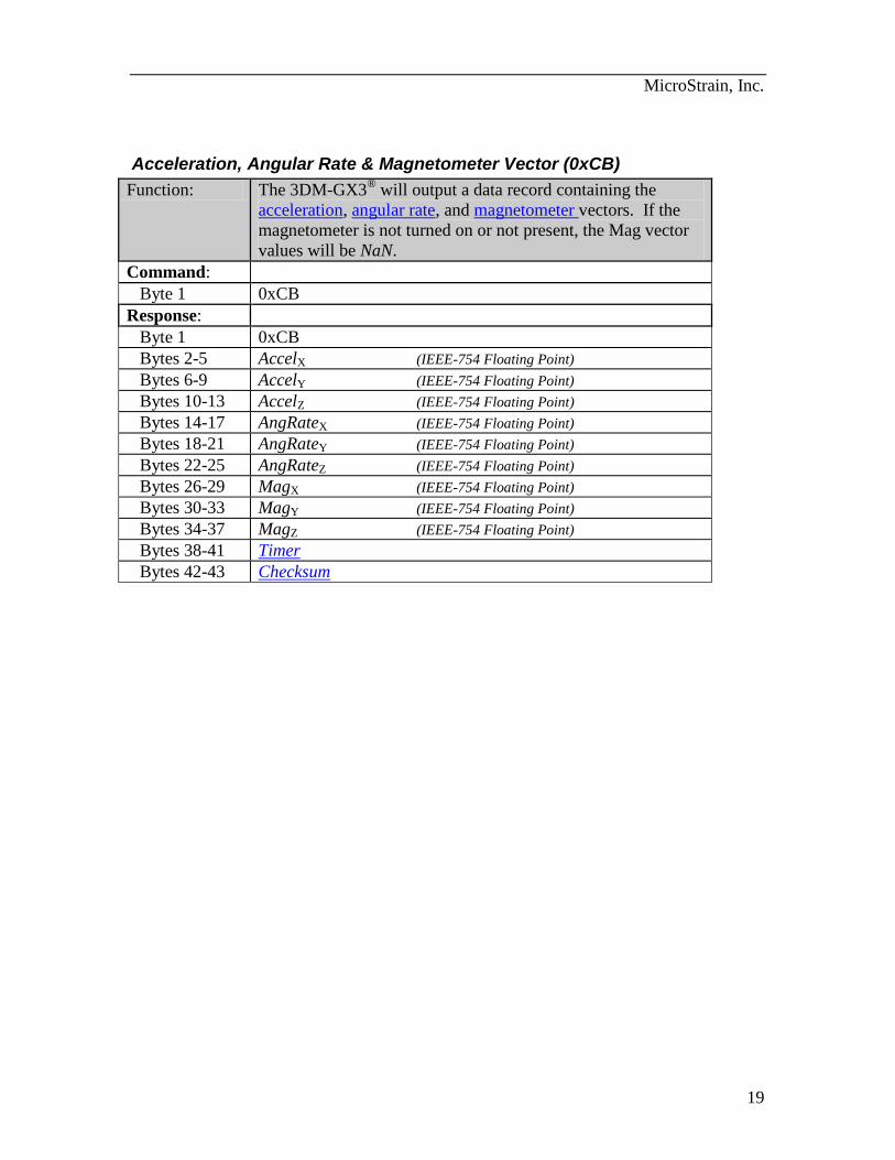
Acceleration, Angular Rate & Magnetometer Vector (0xCB)
Function: The 3DM-GX3®
will output a data record containing the
acceleration, angular rate, and magnetometer vectors. If the
magnetometer is not turned on or not present, the Mag vector
values will be NaN.
Command:
Byte 1 0xCB
Response:
Byte 1 0xCB
Bytes 2-5 AccelX (IEEE-754 Floating Point)
Bytes 6-9 AccelY (IEEE-754 Floating Point)
Bytes 10-13 AccelZ (IEEE-754 Floating Point)
Bytes 14-17 AngRateX (IEEE-754 Floating Point)
Bytes 18-21 AngRateY (IEEE-754 Floating Point)
Bytes 22-25 AngRateZ (IEEE-754 Floating Point)
Bytes 26-29 MagX (IEEE-754 Floating Point)
Bytes 30-33 MagY (IEEE-754 Floating Point)
Bytes 34-37 MagZ (IEEE-754 Floating Point)
Bytes 38-41 Timer
Bytes 42-43 Checksum
MicroStrain, Inc.
20
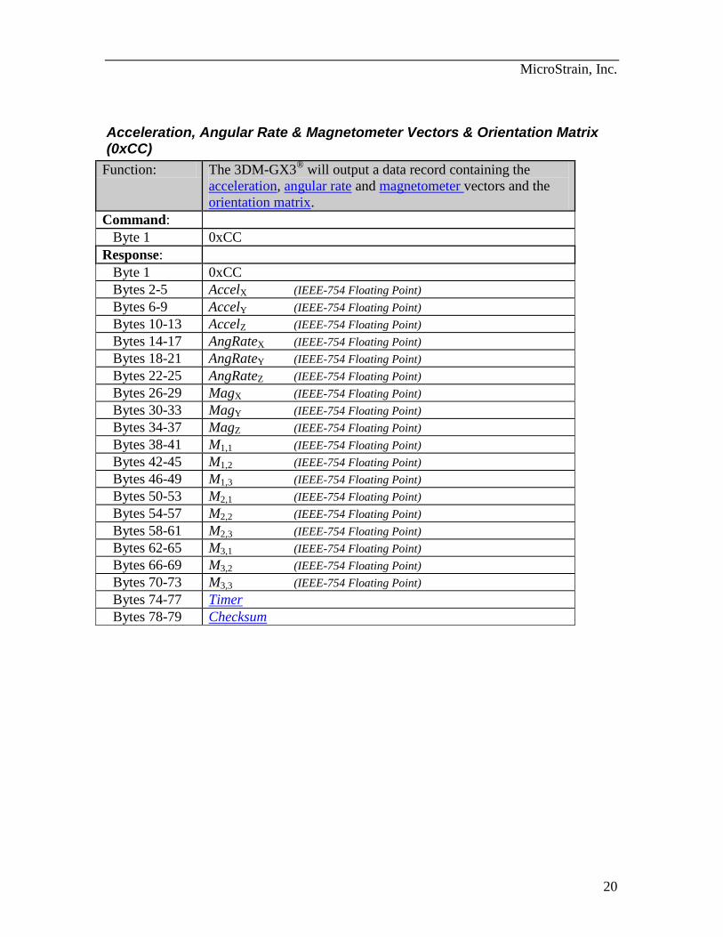
Acceleration, Angular Rate & Magnetometer Vectors & Orientation Matrix (0xCC)
Function: The 3DM-GX3®
will output a data record containing the
acceleration, angular rate and magnetometer vectors and the
orientation matrix.
Command:
Byte 1 0xCC
Response:
Byte 1 0xCC
Bytes 2-5 AccelX (IEEE-754 Floating Point)
Bytes 6-9 AccelY (IEEE-754 Floating Point)
Bytes 10-13 AccelZ (IEEE-754 Floating Point)
Bytes 14-17 AngRateX (IEEE-754 Floating Point)
Bytes 18-21 AngRateY (IEEE-754 Floating Point)
Bytes 22-25 AngRateZ (IEEE-754 Floating Point)
Bytes 26-29 MagX (IEEE-754 Floating Point)
Bytes 30-33 MagY (IEEE-754 Floating Point)
Bytes 34-37 MagZ (IEEE-754 Floating Point)
Bytes 38-41 M1,1 (IEEE-754 Floating Point)
Bytes 42-45 M1,2 (IEEE-754 Floating Point)
Bytes 46-49 M1,3 (IEEE-754 Floating Point)
Bytes 50-53 M2,1 (IEEE-754 Floating Point)
Bytes 54-57 M2,2 (IEEE-754 Floating Point)
Bytes 58-61 M2,3 (IEEE-754 Floating Point)
Bytes 62-65 M3,1 (IEEE-754 Floating Point)
Bytes 66-69 M3,2 (IEEE-754 Floating Point)
Bytes 70-73 M3,3 (IEEE-754 Floating Point)
Bytes 74-77 Timer
Bytes 78-79 Checksum
MicroStrain, Inc.
21
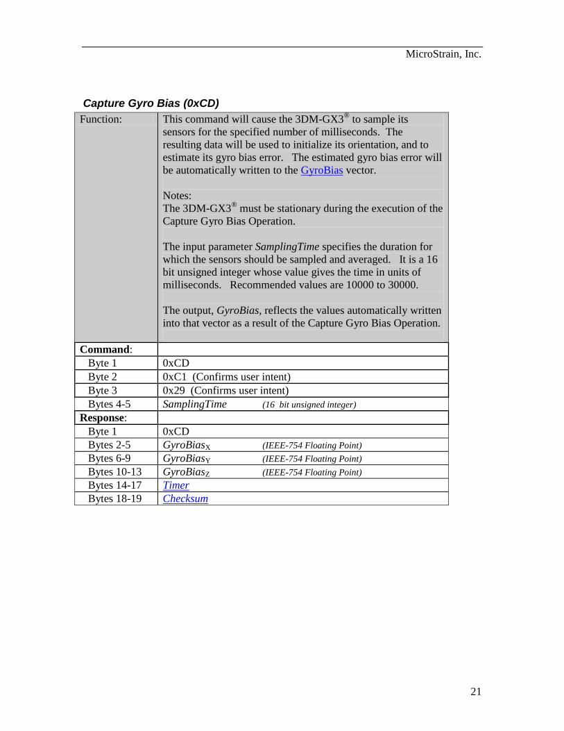
Capture Gyro Bias (0xCD)
Function: This command will cause the 3DM-GX3® to sample its
sensors for the specified number of milliseconds. The
resulting data will be used to initialize its orientation, and to
estimate its gyro bias error. The estimated gyro bias error will
be automatically written to the GyroBias vector.
Notes:
The 3DM-GX3®
must be stationary during the execution of the
Capture Gyro Bias Operation.
The input parameter SamplingTime specifies the duration for
which the sensors should be sampled and averaged. It is a 16
bit unsigned integer whose value gives the time in units of
milliseconds. Recommended values are 10000 to 30000.
The output, GyroBias, reflects the values automatically written
into that vector as a result of the Capture Gyro Bias Operation.
Command:
Byte 1 0xCD
Byte 2 0xC1 (Confirms user intent)
Byte 3 0x29 (Confirms user intent)
Bytes 4-5 SamplingTime (16 bit unsigned integer)
Response:
Byte 1 0xCD
Bytes 2-5 GyroBiasX (IEEE-754 Floating Point)
Bytes 6-9 GyroBiasY (IEEE-754 Floating Point)
Bytes 10-13 GyroBiasZ (IEEE-754 Floating Point)
Bytes 14-17 Timer
Bytes 18-19 Checksum
MicroStrain, Inc.
22
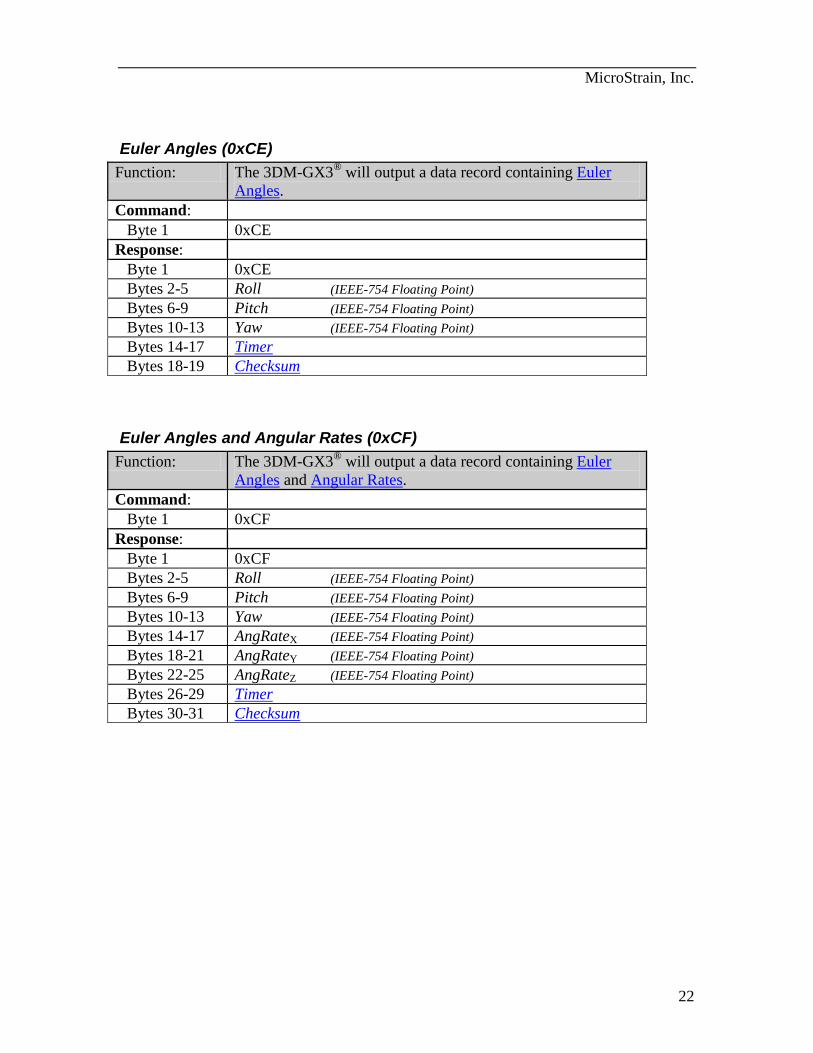
Euler Angles (0xCE)
Function: The 3DM-GX3®
will output a data record containing Euler
Angles.
Command:
Byte 1 0xCE
Response:
Byte 1 0xCE
Bytes 2-5 Roll (IEEE-754 Floating Point)
Bytes 6-9 Pitch (IEEE-754 Floating Point)
Bytes 10-13 Yaw (IEEE-754 Floating Point)
Bytes 14-17 Timer
Bytes 18-19 Checksum
Euler Angles and Angular Rates (0xCF)
Function: The 3DM-GX3®
will output a data record containing Euler
Angles and Angular Rates.
Command:
Byte 1 0xCF
Response:
Byte 1 0xCF
Bytes 2-5 Roll (IEEE-754 Floating Point)
Bytes 6-9 Pitch (IEEE-754 Floating Point)
Bytes 10-13 Yaw (IEEE-754 Floating Point)
Bytes 14-17 AngRateX (IEEE-754 Floating Point)
Bytes 18-21 AngRateY (IEEE-754 Floating Point)
Bytes 22-25 AngRateZ (IEEE-754 Floating Point)
Bytes 26-29 Timer
Bytes 30-31 Checksum
MicroStrain, Inc.
23
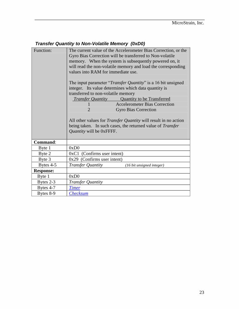
Transfer Quantity to Non-Volatile Memory (0xD0)
Function: The current value of the Accelerometer Bias Correction, or the
Gyro Bias Correction will be transferred to Non-volatile
memory. When the system is subsequently powered on, it
will read the non-volatile memory and load the corresponding
values into RAM for immediate use.
The input parameter “Transfer Quantity” is a 16 bit unsigned
integer. Its value determines which data quantity is
transferred to non-volatile memory
Transfer Quantity Quantity to be Transferred
1 Accelerometer Bias Correction
2 Gyro Bias Correction
All other values for Transfer Quantity will result in no action
being taken. In such cases, the returned value of Transfer
Quantity will be 0xFFFF.
Command:
Byte 1 0xD0
Byte 2 0xC1 (Confirms user intent)
Byte 3 0x29 (Confirms user intent)
Bytes 4-5 Transfer Quantity (16 bit unsigned integer)
Response:
Byte 1 0xD0
Bytes 2-3 Transfer Quantity
Bytes 4-7 Timer
Bytes 8-9 Checksum
MicroStrain, Inc.
24
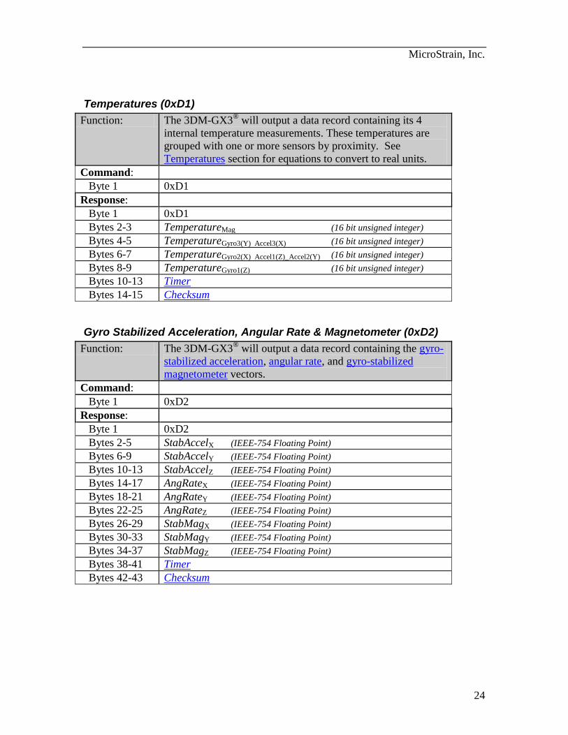
Temperatures (0xD1)
Function: The 3DM-GX3®
will output a data record containing its 4
internal temperature measurements. These temperatures are
grouped with one or more sensors by proximity. See
Temperatures section for equations to convert to real units.
Command:
Byte 1 0xD1
Response:
Byte 1 0xD1
Bytes 2-3 TemperatureMag (16 bit unsigned integer)
Bytes 4-5 TemperatureGyro3(Y) Accel3(X) (16 bit unsigned integer)
Bytes 6-7 TemperatureGyro2(X) Accel1(Z)_Accel2(Y) (16 bit unsigned integer)
Bytes 8-9 TemperatureGyro1(Z) (16 bit unsigned integer)
Bytes 10-13 Timer
Bytes 14-15 Checksum
Gyro Stabilized Acceleration, Angular Rate & Magnetometer (0xD2)
Function: The 3DM-GX3®
will output a data record containing the gyro-
stabilized acceleration, angular rate, and gyro-stabilized
magnetometer vectors.
Command:
Byte 1 0xD2
Response:
Byte 1 0xD2
Bytes 2-5 StabAccelX (IEEE-754 Floating Point)
Bytes 6-9 StabAccelY (IEEE-754 Floating Point)
Bytes 10-13 StabAccelZ (IEEE-754 Floating Point)
Bytes 14-17 AngRateX (IEEE-754 Floating Point)
Bytes 18-21 AngRateY (IEEE-754 Floating Point)
Bytes 22-25 AngRateZ (IEEE-754 Floating Point)
Bytes 26-29 StabMagX (IEEE-754 Floating Point)
Bytes 30-33 StabMagY (IEEE-754 Floating Point)
Bytes 34-37 StabMagZ (IEEE-754 Floating Point)
Bytes 38-41 Timer
Bytes 42-43 Checksum
MicroStrain, Inc.
25
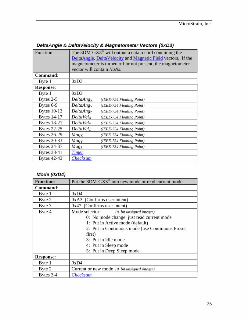
DeltaAngle & DeltaVelocity & Magnetometer Vectors (0xD3)
Function: The 3DM-GX3®
will output a data record containing the
DeltaAngle, DeltaVelocity and Magnetic Field vectors. If the
magnetometer is turned off or not present, the magnetometer
vector will contain NaNs.
Command:
Byte 1 0xD3
Response:
Byte 1 0xD3
Bytes 2-5 DeltaAngX (IEEE-754 Floating Point)
Bytes 6-9 DeltaAngY (IEEE-754 Floating Point)
Bytes 10-13 DeltaAngZ (IEEE-754 Floating Point)
Bytes 14-17 DeltaVelX (IEEE-754 Floating Point)
Bytes 18-21 DeltaVelY (IEEE-754 Floating Point)
Bytes 22-25 DeltaVelZ (IEEE-754 Floating Point)
Bytes 26-29 MagX (IEEE-754 Floating Point)
Bytes 30-33 MagY (IEEE-754 Floating Point)
Bytes 34-37 MagZ (IEEE-754 Floating Point)
Bytes 38-41 Timer
Bytes 42-43 Checksum
Mode (0xD4)
Function: Put the 3DM-GX3® into new mode or read current mode.
Command:
Byte 1 0xD4
Byte 2 0xA3 (Confirms user intent)
Byte 3 0x47 (Confirms user intent)
Byte 4 Mode selector: (8 bit unsigned integer)
0: No mode change: just read current mode
1: Put in Active mode (default)
2: Put in Continuous mode (use Continuous Preset
first)
3: Put in Idle mode
4: Put in Sleep mode
5: Put in Deep Sleep mode
Response:
Byte 1 0xD4
Byte 2 Current or new mode (8 bit unsigned integer)
Bytes 3-4 Checksum
MicroStrain, Inc.
26
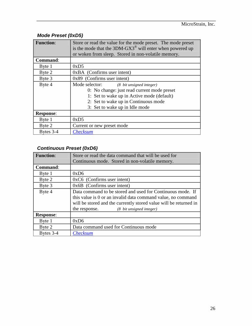
Mode Preset (0xD5)
Function: Store or read the value for the mode preset. The mode preset
is the mode that the 3DM-GX3® will enter when powered up
or woken from sleep. Stored in non-volatile memory.
Command:
Byte 1 0xD5
Byte 2 0xBA (Confirms user intent)
Byte 3 0x89 (Confirms user intent)
Byte 4 Mode selector: (8 bit unsigned integer)
0: No change: just read current mode preset
1: Set to wake up in Active mode (default)
2: Set to wake up in Continuous mode
3: Set to wake up in Idle mode
Response:
Byte 1 0xD5
Byte 2 Current or new preset mode
Bytes 3-4 Checksum
Continuous Preset (0xD6)
Function: Store or read the data command that will be used for
Continuous mode. Stored in non-volatile memory.
Command:
Byte 1 0xD6
Byte 2 0xC6 (Confirms user intent)
Byte 3 0x6B (Confirms user intent)
Byte 4 Data command to be stored and used for Continuous mode. If
this value is 0 or an invalid data command value, no command
will be stored and the currently stored value will be returned in
the response. (8 bit unsigned integer)
Response:
Byte 1 0xD6
Byte 2 Data command used for Continuous mode
Bytes 3-4 Checksum
MicroStrain, Inc.
27
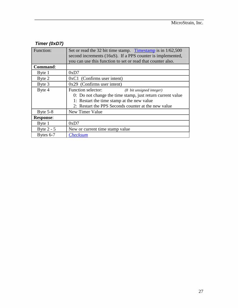
Timer (0xD7)
Function: Set or read the 32 bit time stamp. Timestamp is in 1/62,500
second increments (16uS). If a PPS counter is implemented,
you can use this function to set or read that counter also.
Command:
Byte 1 0xD7
Byte 2 0xC1 (Confirms user intent)
Byte 3 0x29 (Confirms user intent)
Byte 4 Function selector: (8 bit unsigned integer)
0: Do not change the time stamp, just return current value
1: Restart the time stamp at the new value
2: Restart the PPS Seconds counter at the new value
Byte 5-8 New Timer Value
Response:
Byte 1 0xD7
Byte 2 - 5 New or current time stamp value
Bytes 6-7 Checksum
MicroStrain, Inc.
28
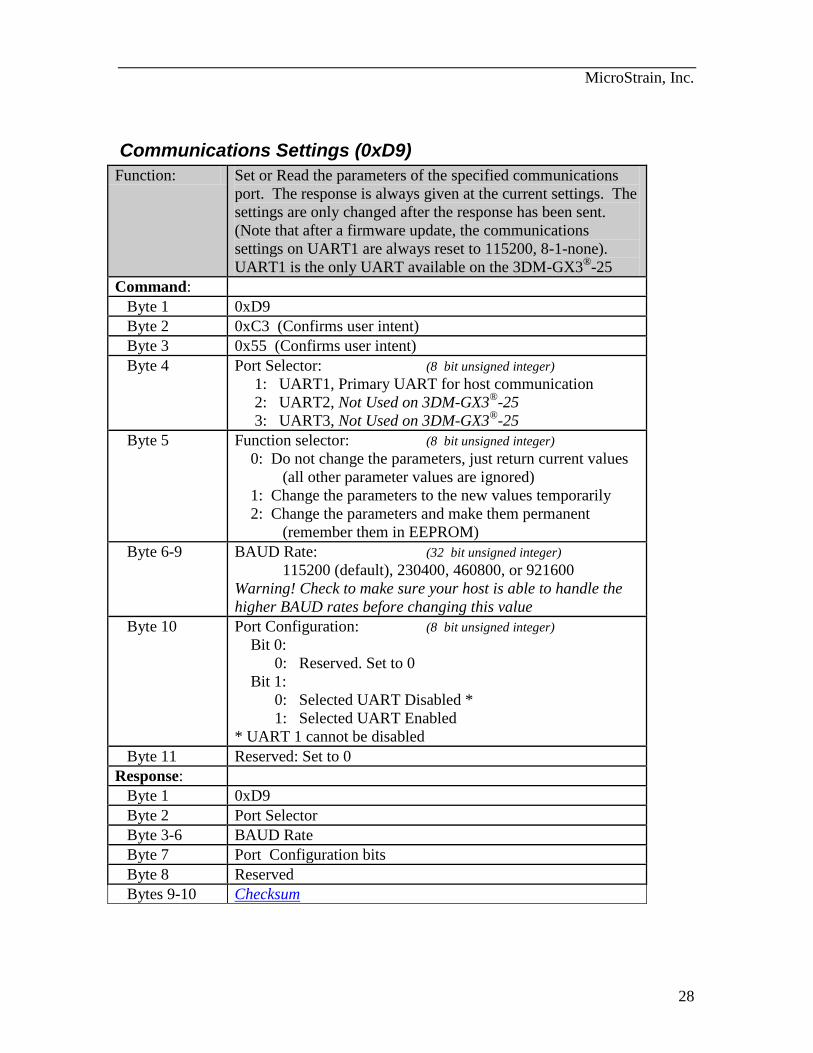
Communications Settings (0xD9)
Function: Set or Read the parameters of the specified communications
port. The response is always given at the current settings. The
settings are only changed after the response has been sent.
(Note that after a firmware update, the communications
settings on UART1 are always reset to 115200, 8-1-none).
UART1 is the only UART available on the 3DM-GX3®-25
Command:
Byte 1 0xD9
Byte 2 0xC3 (Confirms user intent)
Byte 3 0x55 (Confirms user intent)
Byte 4 Port Selector: (8 bit unsigned integer)
1: UART1, Primary UART for host communication
2: UART2, Not Used on 3DM-GX3®
-25
3: UART3, Not Used on 3DM-GX3®
-25
Byte 5 Function selector: (8 bit unsigned integer)
0: Do not change the parameters, just return current values
(all other parameter values are ignored)
1: Change the parameters to the new values temporarily
2: Change the parameters and make them permanent
(remember them in EEPROM)
Byte 6-9 BAUD Rate: (32 bit unsigned integer)
115200 (default), 230400, 460800, or 921600
Warning! Check to make sure your host is able to handle the
higher BAUD rates before changing this value
Byte 10 Port Configuration: (8 bit unsigned integer)
Bit 0:
0: Reserved. Set to 0
Bit 1:
0: Selected UART Disabled *
1: Selected UART Enabled
* UART 1 cannot be disabled
Byte 11 Reserved: Set to 0
Response:
Byte 1 0xD9
Byte 2 Port Selector
Byte 3-6 BAUD Rate
Byte 7 Port Configuration bits
Byte 8 Reserved
Bytes 9-10 Checksum
MicroStrain, Inc.
29
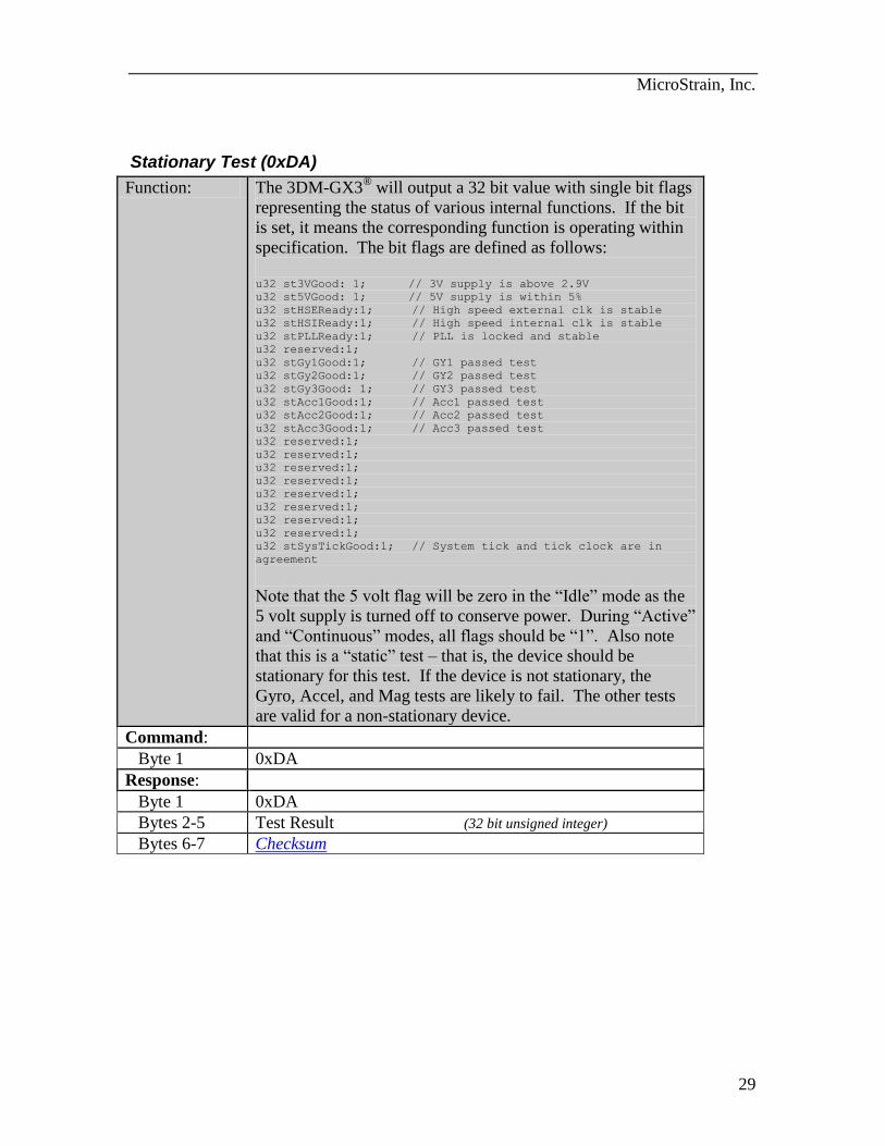
Stationary Test (0xDA)
Function: The 3DM-GX3®
will output a 32 bit value with single bit flags
representing the status of various internal functions. If the bit
is set, it means the corresponding function is operating within
specification. The bit flags are defined as follows:
u32 st3VGood: 1; // 3V supply is above 2.9V
u32 st5VGood: 1; // 5V supply is within 5%
u32 stHSEReady:1; // High speed external clk is stable
u32 stHSIReady:1; // High speed internal clk is stable
u32 stPLLReady:1; // PLL is locked and stable
u32 reserved:1;
u32 stGy1Good:1; // GY1 passed test
u32 stGy2Good:1; // GY2 passed test
u32 stGy3Good: 1; // GY3 passed test
u32 stAcc1Good:1; // Acc1 passed test
u32 stAcc2Good:1; // Acc2 passed test
u32 stAcc3Good:1; // Acc3 passed test
u32 reserved:1;
u32 reserved:1;
u32 reserved:1;
u32 reserved:1;
u32 reserved:1;
u32 reserved:1;
u32 reserved:1;
u32 reserved:1;
u32 stSysTickGood:1; // System tick and tick clock are in
agreement
Note that the 5 volt flag will be zero in the “Idle” mode as the
5 volt supply is turned off to conserve power. During “Active”
and “Continuous” modes, all flags should be “1”. Also note
that this is a “static” test – that is, the device should be
stationary for this test. If the device is not stationary, the
Gyro, Accel, and Mag tests are likely to fail. The other tests
are valid for a non-stationary device.
Command:
Byte 1 0xDA
Response:
Byte 1 0xDA
Bytes 2-5 Test Result (32 bit unsigned integer)
Bytes 6-7 Checksum
MicroStrain, Inc.
30
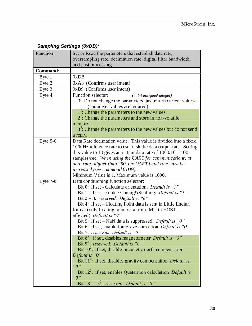
Sampling Settings (0xDB)*
Function: Set or Read the parameters that establish data rate,
oversampling rate, decimation rate, digital filter bandwidth,
and post processing
Command:
Byte 1 0xDB
Byte 2 0xA8 (Confirms user intent)
Byte 3 0xB9 (Confirms user intent)
Byte 4 Function selector: (8 bit unsigned integer)
0: Do not change the parameters, just return current values
(parameter values are ignored)
11: Change the parameters to the new values.
21: Change the parameters and store in non-volatile
memory.
32: Change the parameters to the new values but do not send
a reply.
Byte 5-6 Data Rate decimation value. This value is divided into a fixed
1000Hz reference rate to establish the data output rate. Setting
this value to 10 gives an output data rate of 1000/10 = 100
samples/sec. When using the UART for communications, at
data rates higher than 250, the UART baud rate must be
increased (see command 0xD9).
Minimum Value is 1, Maximum value is 1000.
Byte 7-8 Data conditioning function selector:
Bit 0: if set - Calculate orientation. Default is “1”
Bit 1: if set - Enable Coning&Sculling. Default is “1”
Bit 2 – 3: reserved. Default is “0”
Bit 4: if set – Floating Point data is sent in Little Endian
format (only floating point data from IMU to HOST is
affected). Default is “0”
Bit 5: if set – NaN data is suppressed. Default is “0”
Bit 6: if set, enable finite size correction Default is “0”
Bit 7: reserved. Default is “0”
Bit 82: if set, disables magnetometer Default is “0”
Bit 93: reserved. Default is “0”
Bit 102: if set, disables magnetic north compensation
Default is “0”
Bit 112: if set, disables gravity compensation Default is
“0”
Bit 122: if set, enables Quaternion calculation Default is
“0”
Bit 13 – 152: reserved. Default is “0”
MicroStrain, Inc.
31
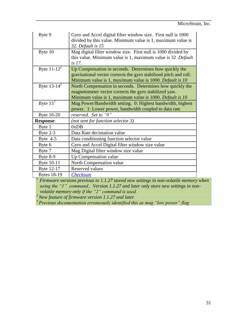
Byte 9 Gyro and Accel digital filter window size. First null is 1000
divided by this value. Minimum value is 1, maximum value is
32. Default is 15
Byte 10 Mag digital filter window size. First null is 1000 divided by
this value. Minimum value is 1, maximum value is 32 Default
is 17.
Byte 11-122 Up Compensation in seconds. Determines how quickly the
gravitational vector corrects the gyro stabilized pitch and roll.
Minimum value is 1, maximum value is 1000. Default is 10
Byte 13-142 North Compensation in seconds. Determines how quickly the
magnetometer vector corrects the gyro stabilized yaw.
Minimum value is 1, maximum value is 1000. Default is 10
Byte 152 Mag Power/Bandwidth setting. 0: Highest bandwidth, highest
power. 1: Lower power, bandwidth coupled to data rate
Byte 16-20 reserved. Set to “0”
Response: (not sent for function selector 3)
Byte 1 0xDB
Byte 2-3 Data Rate decimation value
Byte 4-5 Data conditioning function selector value
Byte 6 Gyro and Accel Digital filter window size value
Byte 7 Mag Digital filter window size value
Byte 8-9 Up Compensation value
Byte 10-11 North Compensation value
Byte 12-17 Reserved values
Bytes 18-19 Checksum 1
Firmware versions previous to 1.1.27 stored new settings in non-volatile memory when
using the “1” command.. Version 1.1.27 and later only store new settings in non-
volatile memory only if the “2” command is used. 2
New feature of firmware version 1.1.27 and later 3
Previous documentation erroneously identified this as mag “low power” flag

MicroStrain, Inc.
32
Realign Up and North (0xDD)
Firmware version 1.1.27 and above
Function: This command will realign the “Up” and “North” vectors
(Gyro Stabilized) using the specified time constants. This
temporarily changes the Up and North comp gains to
accelerate the realignment to the gravitational and magnetic
north vectors (see Bytes 11-14 of the Sampling Settings
command).
Command:
Byte 1 0xDD
Byte 2 0x54 (Confirms user intent)
Byte 3 0x4C (Confirms user intent)
Byte 4 Function selector: (8 bit unsigned integer)
0: Realign Up and North.
3: Realign Up and North but do not send a reply.
Byte 5 Up Realign: 1-100: Realign time in 1/10 seconds (to 90%)
255: Do not realign this vector
Byte 6 North Realign: 1-100: Realign time in 1/10 seconds (to 90%)
255: Do not realign this vector
Bytes 7-10 Reserved: Set to 0
Response: (not sent for function selector 3)
Byte 1 0xDD
Byte 2-5 Reserved: returns undetermined value
Bytes 6-7 Checksum
MicroStrain, Inc.
33
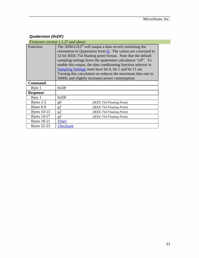
Quaternion (0xDF)
Firmware version 1.1.27 and above
Function: The 3DM-GX3®
will output a data record containing the
orientation in Quaternion form Q. The values are conveyed in
32 bit IEEE-754 floating point format. Note that the default
sampling settings leave the quaternion calculation “off”. To
enable this output, the data conditioning function selector in
Sampling Settings must have bit 0, bit 1 and bit 11 set.
Turning this calculation on reduces the maximum data rate to
500Hz and slightly increases power consumption.
Command:
Byte 1 0xDF
Response:
Byte 1 0xDF
Bytes 2-5 q0 (IEEE-754 Floating Point)
Bytes 6-9 q1 (IEEE-754 Floating Point)
Bytes 10-13 q2 (IEEE-754 Floating Point)
Bytes 14-17 q3 (IEEE-754 Floating Point)
Bytes 18-21 Timer
Bytes 22-23 Checksum
MicroStrain, Inc.
34
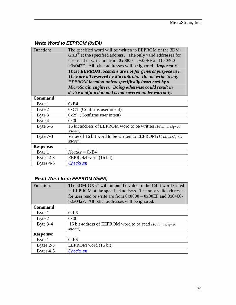
Write Word to EEPROM (0xE4)
Function: The specified word will be written to EEPROM of the 3DM-
GX3® at the specified address. The only valid addresses for
user read or write are from 0x0000 – 0x00EF and 0x0400-
>0x042F. All other addresses will be ignored. Important!
These EEPROM locations are not for general purpose use.
They are all reserved by MicroStrain. Do not write to any
EEPROM location unless specifically instructed by a
MicroStrain engineer. Doing otherwise could result in
device malfunction and is not covered under warranty.
Command:
Byte 1 0xE4
Byte 2 0xC1 (Confirms user intent)
Byte 3 0x29 (Confirms user intent)
Byte 4 0x00
Byte 5-6 16 bit address of EEPROM word to be written (16 bit unsigned
integer)
Byte 7-8 Value of 16 bit word to be written to EEPROM (16 bit unsigned
integer)
Response:
Byte 1 Header = 0xE4
Bytes 2-3 EEPROM word (16 bit)
Bytes 4-5 Checksum
Read Word from EEPROM (0xE5)
Function: The 3DM-GX3®
will output the value of the 16bit word stored
in EEPROM at the specified address. The only valid addresses
for user read or write are from 0x0000 – 0x00EF and 0x0400-
>0x042F. All other addresses will be ignored.
Command:
Byte 1 0xE5
Byte 2 0x00
Byte 3-4 16 bit address of EEPROM word to be read (16 bit unsigned
integer)
Response:
Byte 1 0xE5
Bytes 2-3 EEPROM word (16 bit)
Bytes 4-5 Checksum
MicroStrain, Inc.
35
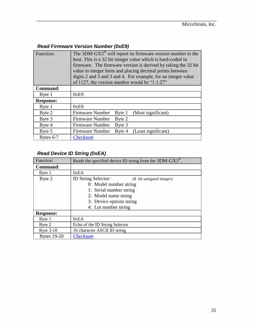
Read Firmware Version Number (0xE9)
Function: The 3DM-GX3®
will report its firmware version number to the
host. This is a 32 bit integer value which is hard-coded in
firmware. The firmware version is derived by taking the 32 bit
value in integer form and placing decimal points between
digits 2 and 3 and 3 and 4. For example, for an integer value
of 1127, the version number would be “1.1.27”
Command:
Byte 1 0xE9
Response:
Byte 1 0xE9
Byte 2 Firmware Number Byte 1 (Most significant)
Byte 3 Firmware Number Byte 2
Byte 4 Firmware Number Byte 3
Byte 5 Firmware Number Byte 4 (Least significant)
Bytes 6-7 Checksum
Read Device ID String (0xEA)
Function: Reads the specified device ID string from the 3DM-GX3®
.
Command:
Byte 1 0xEA
Byte 2 ID String Selector: (8 bit unsigned integer)
0: Model number string
1: Serial number string
2: Model name string
3: Device options string
4: Lot number string
Response:
Byte 1 0xEA
Byte 2 Echo of the ID String Selector
Byte 3-18 16 character ASCII ID string
Bytes 19-20 Checksum

MicroStrain, Inc.
36
Stop Continuous Mode (no reply) (0xFA)
Function: This command will stop the continuous mode of the 3DM-
GX3® and place it in Active mode without generating a
response packet.
Command:
Byte 1 0xFA
Byte 2 0x75 (Confirms user intent)
Byte 3 0xB4 (Confirms user intent)
Response:
None
Device Reset (no reply) (0xFE)
Function: This command will do a soft reset of the 3DM-GX3®.
Command:
Byte 1 0xFE
Byte 2 0x9E (Confirms user intent)
Byte 3 0x3A (Confirms user intent)
Response:
None
MicroStrain, Inc.
37
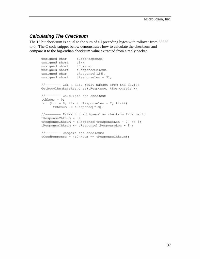
Calculating The Checksum
The 16 bit checksum is equal to the sum of all preceding bytes with rollover from 65535
to 0. The C code snippet below demonstrates how to calculate the checksum and
compare it to the big-endian checksum value extracted from a reply packet.
unsigned char tGoodResponse;
unsigned short tix;
unsigned short tChksum;
unsigned short tResponseChksum;
unsigned char tResponse[128];
unsigned short tResponseLen = 31;
//-------- Get a data reply packet from the device
GetAccelAngRateResponse(tResponse, tResponseLen);
//-------- Calculate the checksum
tChksum = 0;
for (tix = 0; tix < tResponseLen - 2; tix++)
tChksum += tResponse[tix];
//-------- Extract the big-endian checksum from reply
tResponseChksum = 0;
tResponseChksum = tResponse[tResponseLen - 2] << 8;
tResponseChksum += tResponse[tResponseLen - 1];
//-------- Compare the checksums
tGoodResponse = (tChksum == tResponseChksum);
MicroStrain, Inc.
38
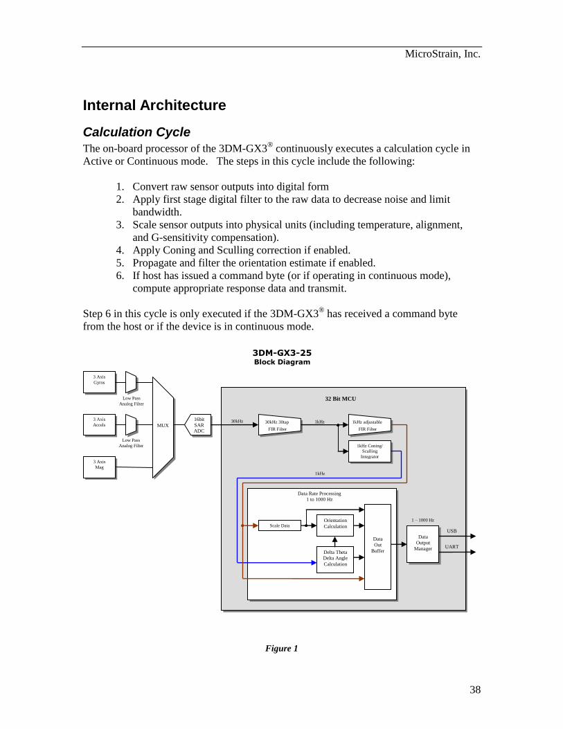
Internal Architecture
Calculation Cycle
The on-board processor of the 3DM-GX3® continuously executes a calculation cycle in
Active or Continuous mode. The steps in this cycle include the following:
1. Convert raw sensor outputs into digital form
2. Apply first stage digital filter to the raw data to decrease noise and limit
bandwidth.
3. Scale sensor outputs into physical units (including temperature, alignment,
and G-sensitivity compensation).
4. Apply Coning and Sculling correction if enabled.
5. Propagate and filter the orientation estimate if enabled.
6. If host has issued a command byte (or if operating in continuous mode),
compute appropriate response data and transmit.
Step 6 in this cycle is only executed if the 3DM-GX3® has received a command byte
from the host or if the device is in continuous mode.
Figure 1
3 Axis
Gyros
3 Axis
Accels
Low Pass
Analog Filter
16bit
SAR ADC
32 Bit MCU
Low Pass
Analog Filter
Scale Data
1kHz Coning/
Sculling
Integrator
Delta Theta
Delta Angle
Calculation
Orientation
Calculation
3 Axis
Mag
Data
Output
Manager
USB
UART
Data Rate Processing
1 to 1000 Hz
3DM-GX3-25 Block Diagram
MUX 30kHz 30tap
FIR Filter
1kHz adjustable
FIR Filter
Data
Out
Buffer
30kHz 1kHz
1kHz
1 – 1000 Hz
MicroStrain, Inc.
39
The calculation cycle continuously repeats itself (even if no data is requested by the
host). The time required to complete a calculation cycle determines the fundamental
limit on the maximum data output rate.
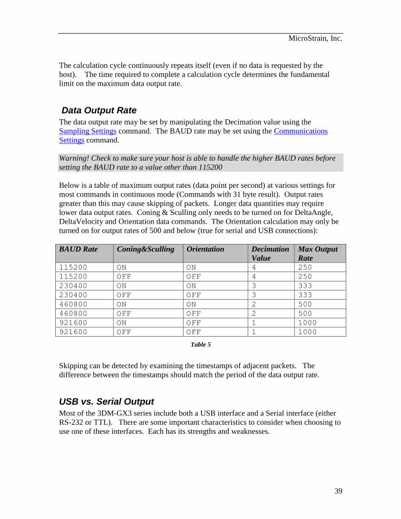
Data Output Rate
The data output rate may be set by manipulating the Decimation value using the
Sampling Settings command. The BAUD rate may be set using the Communications
Settings command.
Warning! Check to make sure your host is able to handle the higher BAUD rates before
setting the BAUD rate to a value other than 115200
Below is a table of maximum output rates (data point per second) at various settings for
most commands in continuous mode (Commands with 31 byte result). Output rates
greater than this may cause skipping of packets. Longer data quantities may require
lower data output rates. Coning & Sculling only needs to be turned on for DeltaAngle,
DeltaVelocity and Orientation data commands. The Orientation calculation may only be
turned on for output rates of 500 and below (true for serial and USB connections):
BAUD Rate Coning&Sculling Orientation Decimation
Value
Max Output
Rate
115200 ON ON 4 250
115200 OFF OFF 4 250
230400 ON ON 3 333
230400 OFF OFF 3 333
460800 ON ON 2 500
460800 OFF OFF 2 500
921600 ON OFF 1 1000
921600 OFF OFF 1 1000
Table 5
Skipping can be detected by examining the timestamps of adjacent packets. The
difference between the timestamps should match the period of the data output rate.
USB vs. Serial Output
Most of the 3DM-GX3 series include both a USB interface and a Serial interface (either
RS-232 or TTL). There are some important characteristics to consider when choosing to
use one of these interfaces. Each has its strengths and weaknesses.
MicroStrain, Inc.
40
USB
USB has several compelling features:
1. Power is supplied by the cable from the host computer (no external supply
required)
2. The bandwidth is very high allowing even the largest records to be transferred
at high data rates (up to 1000Hz).
3. USB is a universal standard and is thus supported by most host devices such
as laptop computers.
The disadvantages of USB are:
1. It requires special drivers for each device type. The 3DM-GX3 uses a generic
“Virtual COM Port” type of driver interface which is supported by the
usbser.sys driver built into Windows.
2. The transfer of data from a connected device is completely controlled by the
host – that is if the host doesn’t want to listen to a USB device, it can ignore it
momentarily.
3. The latency of the data is not deterministic. The host will get to you when
they can get to you which may be right now or maybe in a millisecond or two.
It is the second disadvantage that can sometimes cause “packet drops” or gaps in data.
The 3DM-GX3 can buffer a small amount of data during these host “snubs” but at high
data rates, gaps can occur. You can avoid these gaps by minimizing the user interface
activity and/or the number of programs being run simultaneously on the host machine. It
is good practice to always monitor the timestamp of the packets and check that the
interval is what you expect it to be. You should not experience packet drops frequently,
but they cannot be completely avoided.
The third disadvantage could be a problem in systems where latency must be short and/or
guaranteed as in autopilots or platform stabilization systems where sensor output is part
of a feedback network.
Fortunately, the serial interface provides almost a mirror opposite of the USB advantages
and disadvantages...
Serial
The advantages of serial are:
1. It does not require special drivers – serial data is transferred “as is” with no
additional wrapping, handshaking, or protocol.
2. The transfer of data is controlled by the sensor. Data is always transmitted as
soon as it is ready.

MicroStrain, Inc.
41
3. The latency of the data is deterministic. Because there is no flow control, the data
is always transmitted immediately with very little latency.
The disadvantages of serial are:
1. It requires an external power supply
2. There is no flow control - the host has to be fast enough to process the data as fast
or faster than it is coming in from the sensor or it may drop packets.
3. The bandwidth of the serial UART is limited and so some larger data packets
cannot be accommodated at the highest sample rates.
Most microcontrollers and almost all PC’s can handle even the highest data rates of the
3DM-GX3, however managing the volume of the incoming data either through storage or
processing algorithms can be problematic.
In general it is very convenient to develop interface code on a host computer using the
USB interface and then switch to a serial interface for the embedded target. For the most
part the interfaces will perform equivalently, but you must pay attention to the differences
especially in applications that cannot tolerate packet drops or inconsistent latency. In
addition, it is always good practice to monitor the timestamps and checksums of the
incoming packets so you can be aware of packet drops and re-sync with the data stream if
you do miss a few bytes.
MicroStrain, Inc.
42
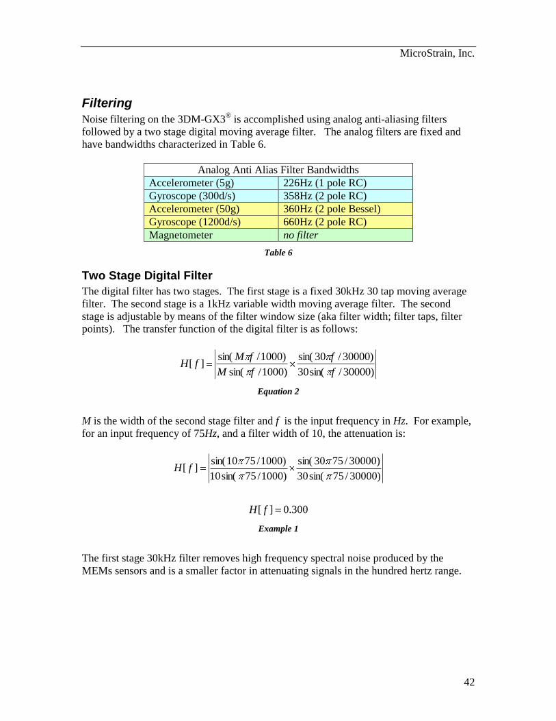
Filtering
Noise filtering on the 3DM-GX3® is accomplished using analog anti-aliasing filters
followed by a two stage digital moving average filter. The analog filters are fixed and
have bandwidths characterized in Table 6.
Analog Anti Alias Filter Bandwidths
Accelerometer (5g) 226Hz (1 pole RC)
Gyroscope (300d/s) 358Hz (2 pole RC)
Accelerometer (50g) 360Hz (2 pole Bessel)
Gyroscope (1200d/s) 660Hz (2 pole RC)
Magnetometer no filter
Table 6
Two Stage Digital Filter
The digital filter has two stages. The first stage is a fixed 30kHz 30 tap moving average
filter. The second stage is a 1kHz variable width moving average filter. The second
stage is adjustable by means of the filter window size (aka filter width; filter taps, filter
points). The transfer function of the digital filter is as follows:
)30000/sin(30
)30000/30sin(
)1000/sin(
)1000/sin(][
f
f
fM
fMfH
Equation 2
M is the width of the second stage filter and f is the input frequency in Hz. For example,
for an input frequency of 75Hz, and a filter width of 10, the attenuation is:
300.0][
)30000/75sin(30
)30000/7530sin(
)1000/75sin(10
)1000/7510sin(][
fH
fH
Example 1
The first stage 30kHz filter removes high frequency spectral noise produced by the
MEMs sensors and is a smaller factor in attenuating signals in the hundred hertz range.
MicroStrain, Inc.
43
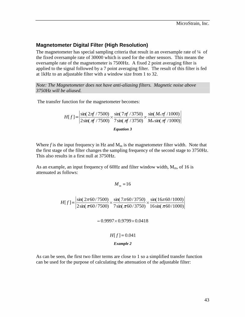
Magnetometer Digital Filter (High Resolution)
The magnetometer has special sampling criteria that result in an oversample rate of ¼ of
the fixed oversample rate of 30000 which is used for the other sensors. This means the
oversample rate of the magnetometer is 7500Hz. A fixed 2 point averaging filter is
applied to the signal followed by a 7 point averaging filter. The result of this filter is fed
at 1kHz to an adjustable filter with a window size from 1 to 32.
Note: The Magnetometer does not have anti-aliasing filters. Magnetic noise above
3750Hz will be aliased.
The transfer function for the magnetometer becomes:
)1000/sin(
)1000/sin(
)3750/sin(7
)3750/7sin(
)7500/sin(2
)7500/2sin(][
fM
fM
f
f
f
ffH
m
m
Equation 3
Where f is the input frequency in Hz and Mm is the magnetometer filter width. Note that
the first stage of the filter changes the sampling frequency of the second stage to 3750Hz.
This also results in a first null at 3750Hz.
As an example, an input frequency of 60Hz and filter window width, Mm, of 16 is
attenuated as follows:
041.0][
0418.09799.09997.0
)1000/60sin(16
)1000/6016sin(
)3750/60sin(7
)3750/607sin(
)7500/60sin(2
)7500/602sin(][
16
fH
fH
M m
Example 2
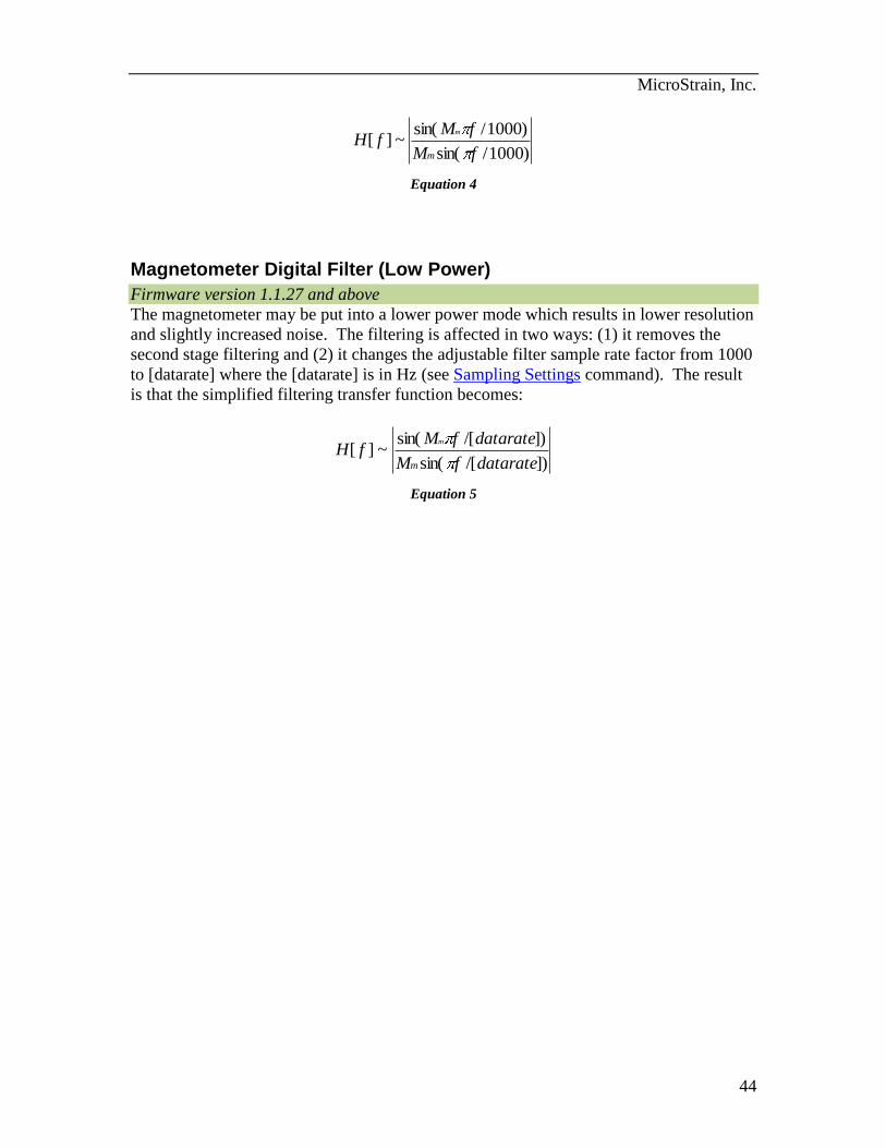
As can be seen, the first two filter terms are close to 1 so a simplified transfer function
can be used for the purpose of calculating the attenuation of the adjustable filter:
MicroStrain, Inc.
44
)1000/sin(
)1000/sin(~][
fM
fMfH
m
m
Equation 4
Magnetometer Digital Filter (Low Power)
Firmware version 1.1.27 and above
The magnetometer may be put into a lower power mode which results in lower resolution
and slightly increased noise. The filtering is affected in two ways: (1) it removes the
second stage filtering and (2) it changes the adjustable filter sample rate factor from 1000
to [datarate] where the [datarate] is in Hz (see Sampling Settings command). The result
is that the simplified filtering transfer function becomes:
])/[sin(
])/[sin(~][
dataratefM
dataratefMfH
m
m
Equation 5
MicroStrain, Inc.
45
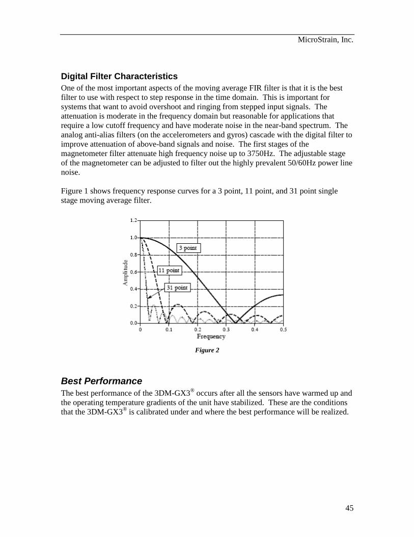
Digital Filter Characteristics
One of the most important aspects of the moving average FIR filter is that it is the best
filter to use with respect to step response in the time domain. This is important for
systems that want to avoid overshoot and ringing from stepped input signals. The
attenuation is moderate in the frequency domain but reasonable for applications that
require a low cutoff frequency and have moderate noise in the near-band spectrum. The
analog anti-alias filters (on the accelerometers and gyros) cascade with the digital filter to
improve attenuation of above-band signals and noise. The first stages of the
magnetometer filter attenuate high frequency noise up to 3750Hz. The adjustable stage
of the magnetometer can be adjusted to filter out the highly prevalent 50/60Hz power line
noise.
Figure 1 shows frequency response curves for a 3 point, 11 point, and 31 point single
stage moving average filter.
Figure 2
Best Performance
The best performance of the 3DM-GX3® occurs after all the sensors have warmed up and
the operating temperature gradients of the unit have stabilized. These are the conditions
that the 3DM-GX3® is calibrated under and where the best performance will be realized.
MicroStrain, Inc.
46
Data Quantities Available The 3DM-GX3
® is capable of calculating and reporting data of various types. These can
be accessed by selecting and sending the appropriate command byte (see Command Set
Summary and Command Reference sections). The data that is available is the following:
RawAccel – (3 components)
These are the raw voltage outputs of the three axis accelerometer. They are expressed in
terms of A/D converter codes where 0 represents 0.0 Volts, and 131071 represents ~5
volts (17 bits of resolution). The accelerometer signals do not actually register the full
range of possible codes – the range varies slightly from device to device. The raw accel
values are not scaled into physical units, nor are the individual components necessarily
orthogonal or aligned with the local coordinate system. These quantities are not
recommended for most applications. They are useful for validating individual accel raw
signal quality.
3
2
1
RawAccel
RawAccel
RawAccel
RawAccel
Equation 6
Data Format: 3 element array of 32bit floating point values in IEEE-754 format.
Note: Although the A/D converter fundamentally produces integer quantities, floating
point values are used to accommodate the 3DM-GX3®’s ability to oversample and
average successive readings.
RawAngRate – (3 components)
These are the raw voltage outputs of the three axis angular rate sensor. They are
expressed in terms of A/D converter codes where 0 represents 0.0 Volts, and 131071
represents ~5 volts (17 bits of resolution). The gyro signals do not actually register the
full range of possible codes – the range varies slightly from device to device. The raw
values are not scaled into physical units, nor are the individual components necessarily
orthogonal, or forming a right-handed coordinate system. These quantities are not
recommends for most applications.
MicroStrain, Inc.
47
3
2
1
RawAngRate
RawAngRate
RawAngRate
RawAngRate
Equation 7
Data Format: 3 element array of 32bit floating point values in IEEE-754 format.
Note: Although the A/D converter fundamentally produces integer quantities, floating
point values are used to accommodate the 3DM-GX3®’s ability to oversample and
average successive readings.
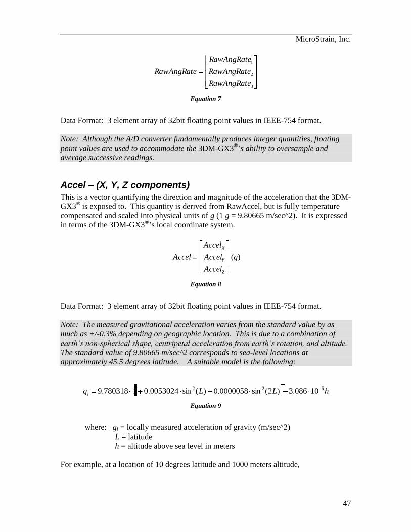
Accel – (X, Y, Z components)
This is a vector quantifying the direction and magnitude of the acceleration that the 3DM-
GX3® is exposed to. This quantity is derived from RawAccel, but is fully temperature
compensated and scaled into physical units of g (1 g = 9.80665 m/sec^2). It is expressed
in terms of the 3DM-GX3®’s local coordinate system.
Z
Y
X
Accel
Accel
Accel
Accel (g)
Equation 8
Data Format: 3 element array of 32bit floating point values in IEEE-754 format.
Note: The measured gravitational acceleration varies from the standard value by as
much as +/-0.3% depending on geographic location. This is due to a combination of
earth’s non-spherical shape, centripetal acceleration from earth’s rotation, and altitude.
The standard value of 9.80665 m/sec^2 corresponds to sea-level locations at
approximately 45.5 degrees latitude. A suitable model is the following:
hLLgl
622 10086.3)2(sin0000058.0)(sin0.005302419.780318
Equation 9
where: gl = locally measured acceleration of gravity (m/sec^2)
L = latitude
h = altitude above sea level in meters
For example, at a location of 10 degrees latitude and 1000 meters altitude,
MicroStrain, Inc.
48
gl = 9.77879m/sec2. This is equal to 0.99716*g. Therefore, under static conditions, the
Accel vector output by the 3DM-GX3® would have a magnitude of 0.997g.
StabAccel – (X, Y, Z components)
This is a vector which represents the complementary filter’s best estimate of the vertical
direction. Under stationary conditions, it should be equal to Accel. In dynamic
conditions, Accel will be sensitive to both gravitational acceleration as well as linear
acceleration. The Complementary filter computes StabAccel which is its estimate of the
gravitation acceleration only, even thought the system may be exposed to significant
linear acceleration.
Z
Y
X
StabAccel
StabAccel
StabAccel
StabAccel (g)
Data Format: 3 element array of 32bit floating point values in IEEE-754 format.
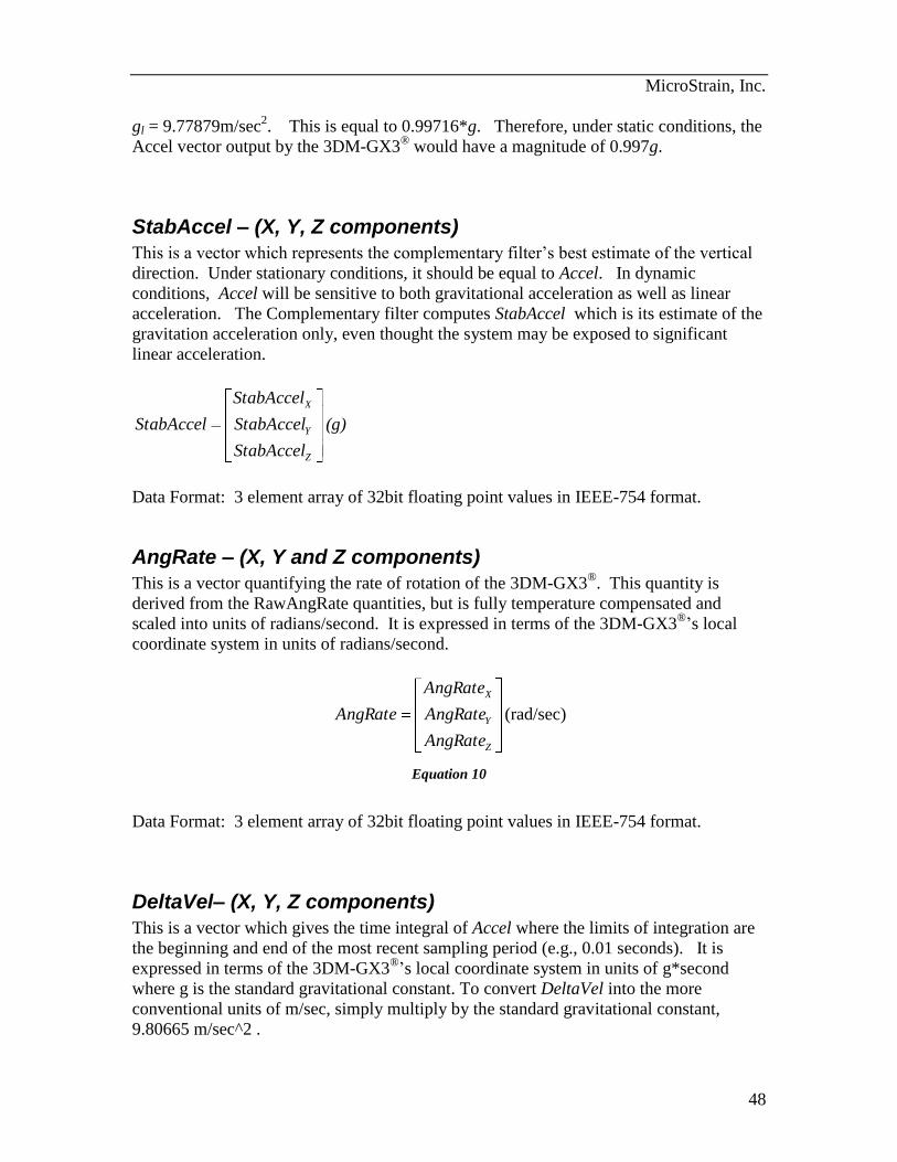
AngRate – (X, Y and Z components)
This is a vector quantifying the rate of rotation of the 3DM-GX3®. This quantity is
derived from the RawAngRate quantities, but is fully temperature compensated and
scaled into units of radians/second. It is expressed in terms of the 3DM-GX3®’s local
coordinate system in units of radians/second.
Z
Y
X
AngRate
AngRate
AngRate
AngRate (rad/sec)
Equation 10
Data Format: 3 element array of 32bit floating point values in IEEE-754 format.
DeltaVel– (X, Y, Z components)
This is a vector which gives the time integral of Accel where the limits of integration are
the beginning and end of the most recent sampling period (e.g., 0.01 seconds). It is
expressed in terms of the 3DM-GX3®’s local coordinate system in units of g*second
where g is the standard gravitational constant. To convert DeltaVel into the more
conventional units of m/sec, simply multiply by the standard gravitational constant,
9.80665 m/sec^2 .
MicroStrain, Inc.
49
Z
Y
X
DeltaVel
DeltaVel
DeltaVel
DeltaVel (g*sec)
Equation 11
Data Format: 3 element array of 32bit floating point values in IEEE-754 format.
DeltaAng– (X, Y, Z components)
This is a vector which gives the time integral of AngRate where the limits of integration
are the beginning and end of the most recent sampling period (eg., 0.01 seconds). It is
expressed in terms of the 3DM-GX3®’s local coordinate system in units of radians.
Z
Y
X
DeltaVel
DeltaVel
DeltaVel
DeltaVel (rad)
Equation 12
Data Format: 3 element array of 32bit floating point values in IEEE-754 format.
Magnetometer– (X, Y, Z components)
This is a vector which gives the instantaneous magnetometer direction and magnitude. It
is fully temperature compensated and is expressed in terms of the 3DM-GX3®’s local
coordinate system in units of Gauss.
Z
Y
X
Mag
Mag
Mag
erMagnetomet (G)
Equation 13
Data Format: 3 element array of 32bit floating point values in IEEE-754 format.
StabMag – (X, Y, Z components)
This is a vector which represents the complementary filter’s best estimate of the
geomagnetic field direction. In the absence of magnetic interference, it should be equal
MicroStrain, Inc.
50
to Magnetometer. When transient magnetic interference is present, Magnetometer will
be subject to transient (possibly large) errors. The Complementary filter computes
StabMag which is its estimate of the geomagnetic field vector only, even thought the
system may be exposed to transient magnetic interference. Note that sustained magnetic
interference cannot be adequately compensated for by the complementary filter.
StabMag
StabMag
StabMag
StabMag Y
X
(G)
Data Format: 3 element array of 32bit floating point values in IEEE-754 format.
Timer
This is a timer value which measures the time since system power-up or timer set
command. To convert the timer value to time in seconds, divide by 62,500. The
system clock has an accuracy of +/- 0.01%.
Data Format: 32 bit unsigned integer value.
Note: The timer value rolls over from its maximum value to 0 approximately every 68719
seconds (~1145 minutes or ~19 hours). The host system must keep track of these
rollovers if an absolute time is required over long periods.
MicroStrain, Inc.
51
M
This is a 9 component coordinate transformation matrix which describes the orientation
of the 3DM-GX3® with respect to the fixed earth coordinate system.
3,32,31,3
3,22,21,2
3,12,11,1
MMM
MMM
MMM
M
M satisfies the following equation:
V_ILi = Mij · V_Ej
Where: V_IL is a vector expressed in the 3DM-GX3®’s local coordinate system.
V_E is the same vector expressed in the stationary, earth-fixed coordinate
system
Data Format: 9 element array of 32bit floating point values in IEEE-754 format.
Note: The elements are arranged in Row major order:
(M1,1, M1,2, M1,3, M2,1, … , M3,2, M3,3).
C
This is a 9 component coordinate transformation matrix which describes the change in
orientation of the 3DM-GX3® during the period of the most recent calculation cycle.
3,32,31,3
3,22,21,2
3,12,11,1
CCC
CCC
CCC
C
M satisfies the following equation:
M2i = Cij · M1ij
Where: M1 is the orientation matrix at the beginning of the calculation cycle.
M2 is the orientation matrix at the end of the calculation cycle.
Data Format: 9 element array of 32bit floating point values in IEEE-754 format.
Note: The elements are arranged in Row major order:
(C1,1, C1,2, C1,3, C2,1, … , C3,2, C3,3).
MicroStrain, Inc.
52
Q
This is a 4 component quaternion which describes the orientation of the 3DM-GX3 with
respect to the fixed earth coordinate quaternion.
3
2
1
0
q
q
q
q
Q
Q satisfies the following equation:
V_ILi = Q-1
• V_E • Q
Where: V_IL is a vector expressed in the 3DM-GX3®’s local coordinate system.
V_E is the same vector expressed in the stationary, earth-fixed coordinate
system
Data Format: 4 element array of 32bit floating point values in IEEE-754 format.
Note: • indicates a quaternion product
Euler Angles
This is a 3 component vector containing the Roll, Pitch and Yaw angles in radians. It is
computed on the 3DM-GX3® from the orientation matrix M.
Yaw
Pitch
Roll
Euler (radians)
Data Format: 3 element vector of 32bit floating point values in IEEE-754 format.
AccelBias – (X, Y, Z components)
This is a 3 component vector quantity in units of g (same as the Accel vector). It is
expressed in terms of the 3DM-GX3®’s local coordinate system. On system power-up,
AccelBias is initialized to a value of [0,0,0].
MicroStrain, Inc.
53
Z
Y
X
AccelBias
AccelBias
AccelBias
AccelBias (g)
Due to imperfections in the accelerometer sensors, the measured Accel vector can be in
error by an additive constant (bias). In some applications, it may be possible for the
user’s software algorithm to estimate this bias. If such an estimate is available, it can be
written into the 3DM-GX3®, in the form of the AccelBias vector. AccelBias will be
subtracted from every measurement of the Accel vector made by the 3DM-GX3® to form
a bias corrected version of the Accel quantity. This will then used as the output quantity,
and for all on-board filtering operations that use Accel. This provides a means by which
bias errors in the accelerometer measurements can be compensated for.
Data Format: 3 element array of 32bit floating point values in IEEE-754 format.
GyroBias – (X, Y, Z components)
This is a 3 component vector quantity in units of rad/sec (same as the AngRate vector).
It is expressed in terms of the 3DM-GX3®’s local coordinate system. On system power-
up, GyroBias is initialized to a value of [0,0,0].
Z
Y
X
GyroBias
GyroBias
GyroBias
GyroBias (g)
Due to imperfections in the angular rate sensors, the measured AngRate vector can be in
error by an additive constant (bias). In some applications, it may be possible for the
user’s software algorithm to estimate this bias. If such an estimate is available, it can be
written into the 3DM-GX3®, in the form of the GyroBias vector. GyroBias will be
subtracted from every measurement of the AngRate vector made by the 3DM-GX3® to
form a bias corrected version of the AngRate quantity. This will then used as the output
quantity, and for all on-board filtering operations that use AngRate. This provides a
means by which bias errors in the angular Rate measurements can be compensated for.
Data Format: 3 element array of 32bit floating point values in IEEE-754 format.
Temperature – (Mag,Accel, GyroX, GyroY, GyroZ components)
This is a 4 element array of 16 bit integers giving the raw A/D converter codes associated
with each of the four on-board temperature sensors.
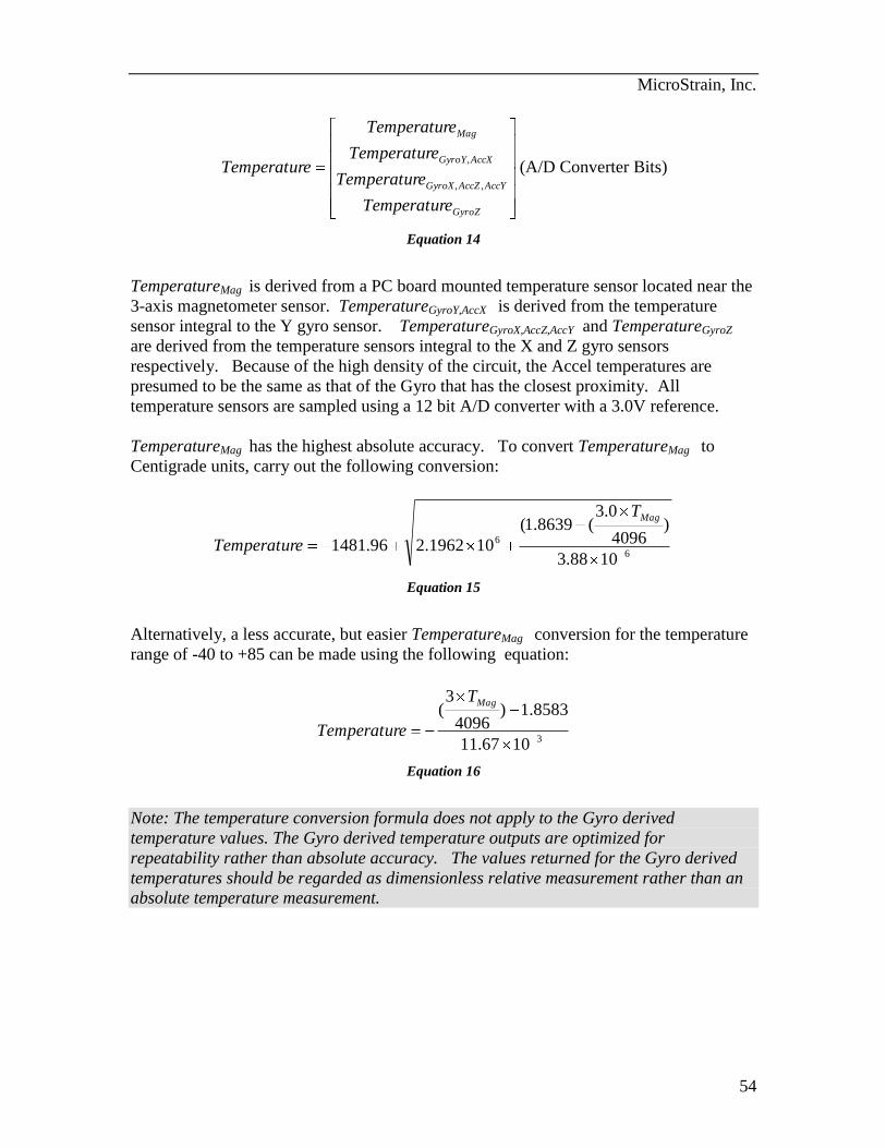
MicroStrain, Inc.
54
GyroZ
AccYAccZGyroX
AccXGyroY
Mag
eTemperatur
eTemperatur
eTemperatur
eTemperatur
eTemperatur,,
,(A/D Converter Bits)
Equation 14
TemperatureMag is derived from a PC board mounted temperature sensor located near the
3-axis magnetometer sensor. TemperatureGyroY,AccX is derived from the temperature
sensor integral to the Y gyro sensor. TemperatureGyroX,AccZ,AccY and TemperatureGyroZ
are derived from the temperature sensors integral to the X and Z gyro sensors
respectively. Because of the high density of the circuit, the Accel temperatures are
presumed to be the same as that of the Gyro that has the closest proximity. All
temperature sensors are sampled using a 12 bit A/D converter with a 3.0V reference.
TemperatureMag has the highest absolute accuracy. To convert TemperatureMag to
Centigrade units, carry out the following conversion:
6
6
1088.3
)4096
0.3(8639.1(
101962.296.1481
MagT
eTemperatur
Equation 15
Alternatively, a less accurate, but easier TemperatureMag conversion for the temperature
range of -40 to +85 can be made using the following equation:
31067.11
8583.1)4096
3(
MagT
eTemperatur
Equation 16
Note: The temperature conversion formula does not apply to the Gyro derived
temperature values. The Gyro derived temperature outputs are optimized for
repeatability rather than absolute accuracy. The values returned for the Gyro derived
temperatures should be regarded as dimensionless relative measurement rather than an
absolute temperature measurement.
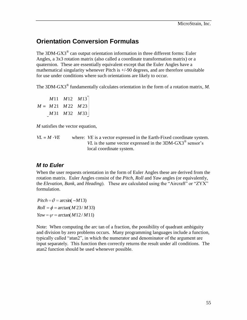
MicroStrain, Inc.
55
Orientation Conversion Formulas
The 3DM-GX3® can output orientation information in three different forms: Euler
Angles, a 3x3 rotation matrix (also called a coordinate transformation matrix) or a
quaternion. These are essentially equivalent except that the Euler Angles have a
mathematical singularity whenever Pitch is +/-90 degrees, and are therefore unsuitable
for use under conditions where such orientations are likely to occur.
The 3DM-GX3® fundamentally calculates orientation in the form of a rotation matrix, M.
333231
232221
131211
MMM
MMM
MMM
M
M satisfies the vector equation,
VEMVL where: VE is a vector expressed in the Earth-Fixed coordinate system.
VL is the same vector expressed in the 3DM-GX3® sensor’s
local coordinate system.
M to Euler
When the user requests orientation in the form of Euler Angles these are derived from the
rotation matrix. Euler Angles consist of the Pitch, Roll and Yaw angles (or equivalently,
the Elevation, Bank, and Heading). These are calculated using the “Aircraft” or “ZYX”
formulation.
)11/12arctan(
)33/23arctan(
)13arcsin(
MMYaw
MMRoll
MPitch
Note: When computing the arc tan of a fraction, the possibility of quadrant ambiguity
and division by zero problems occurs. Many programming languages include a function,
typically called “atan2”, in which the numerator and denominator of the argument are
input separately. This function then correctly returns the result under all conditions. The
atan2 function should be used whenever possible.
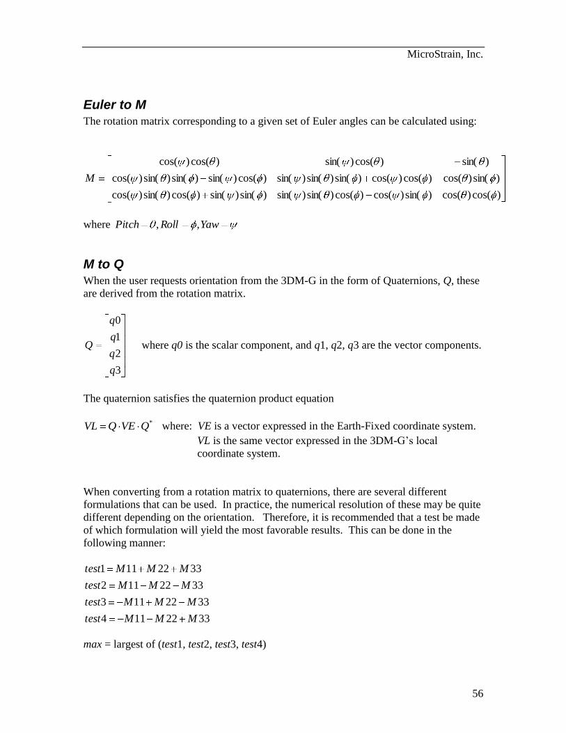
MicroStrain, Inc.
56
Euler to M
The rotation matrix corresponding to a given set of Euler angles can be calculated using:
)cos()cos()sin()cos()cos()sin()sin()sin()sin()cos()sin()cos(
)sin()cos()cos()cos()sin()sin()sin()cos()sin()sin()sin()cos(
)sin()cos()sin()cos()cos(
M
where YawRollPitch ,,
M to Q
When the user requests orientation from the 3DM-G in the form of Quaternions, Q, these
are derived from the rotation matrix.
3
2
1
0
q
q
q
q
Q where q0 is the scalar component, and q1, q2, q3 are the vector components.
The quaternion satisfies the quaternion product equation
*QVEQVL where: VE is a vector expressed in the Earth-Fixed coordinate system.
VL is the same vector expressed in the 3DM-G’s local
coordinate system.
When converting from a rotation matrix to quaternions, there are several different
formulations that can be used. In practice, the numerical resolution of these may be quite
different depending on the orientation. Therefore, it is recommended that a test be made
of which formulation will yield the most favorable results. This can be done in the
following manner:
3322114
3322113
3322112
3322111
MMMtest
MMMtest
MMMtest
MMMtest
max = largest of (test1, test2, test3, test4)
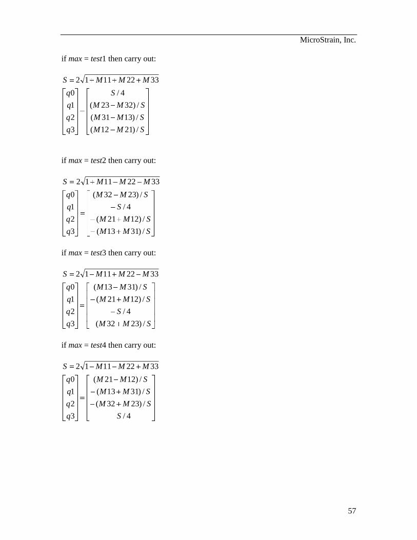
MicroStrain, Inc.
57
if max = test1 then carry out:
SMM
SMM
SMM
S
q
q
q
q
MMMS
/)2112(
/)1331(
/)3223(
4/
3
2
1
0
33221112
if max = test2 then carry out:
SMM
SMM
S
SMM
q
q
q
q
MMMS
/)3113(
/)1221(
4/
/)2332(
3
2
1
0
33221112
if max = test3 then carry out:
SMM
S
SMM
SMM
q
q
q
q
MMMS
/)2332(
4/
/)1221(
/)3113(
3
2
1
0
33221112
if max = test4 then carry out:
4/
/)2332(
/)3113(
/)1221(
3
2
1
0
33221112
S
SMM
SMM
SMM
q
q
q
q
MMMS
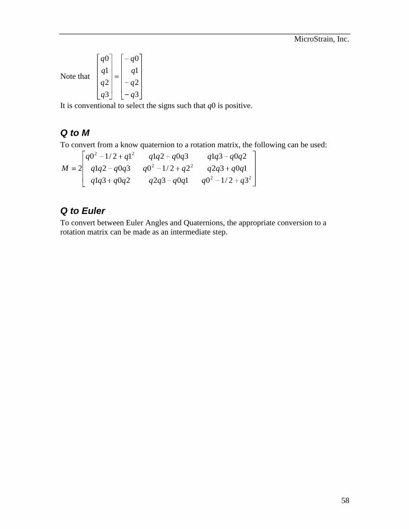
MicroStrain, Inc.
58
Note that
3
2
1
0
3
2
1
0
q
q
q
q
q
q
q
q
It is conventional to select the signs such that q0 is positive.
Q to M
To convert from a know quaternion to a rotation matrix, the following can be used:
22
22
22
32/1010322031
103222/103021
2031302112/10
2
qqqqqqqqqq
qqqqqqqqqq
qqqqqqqqqq
M
Q to Euler
To convert between Euler Angles and Quaternions, the appropriate conversion to a
rotation matrix can be made as an intermediate step.
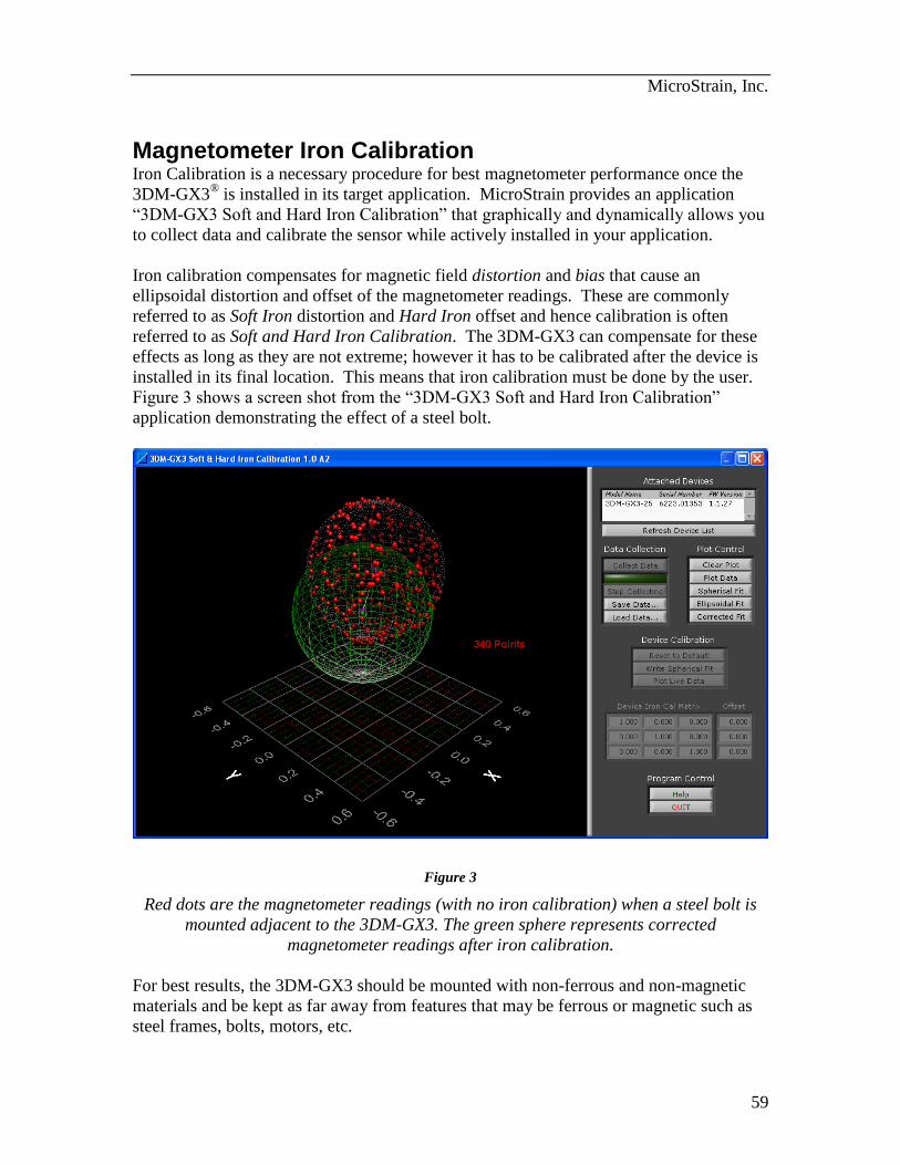
MicroStrain, Inc.
59
Magnetometer Iron Calibration Iron Calibration is a necessary procedure for best magnetometer performance once the
3DM-GX3® is installed in its target application. MicroStrain provides an application
“3DM-GX3 Soft and Hard Iron Calibration” that graphically and dynamically allows you
to collect data and calibrate the sensor while actively installed in your application.
Iron calibration compensates for magnetic field distortion and bias that cause an
ellipsoidal distortion and offset of the magnetometer readings. These are commonly
referred to as Soft Iron distortion and Hard Iron offset and hence calibration is often
referred to as Soft and Hard Iron Calibration. The 3DM-GX3 can compensate for these
effects as long as they are not extreme; however it has to be calibrated after the device is
installed in its final location. This means that iron calibration must be done by the user.
Figure 3 shows a screen shot from the “3DM-GX3 Soft and Hard Iron Calibration”
application demonstrating the effect of a steel bolt.
Figure 3
Red dots are the magnetometer readings (with no iron calibration) when a steel bolt is
mounted adjacent to the 3DM-GX3. The green sphere represents corrected
magnetometer readings after iron calibration.
For best results, the 3DM-GX3 should be mounted with non-ferrous and non-magnetic
materials and be kept as far away from features that may be ferrous or magnetic such as
steel frames, bolts, motors, etc.

MicroStrain, Inc.
60
End of Document