Embed Size (px)
Citation preview
3D Shape Scanning with a Time-of-Flight Camera
Yan Cui1,3, Sebastian Schuon2, Derek Chan2, Sebastian Thrun2, Christian Theobalt1
1MPI Informatik 2Stanford University 3Augmented Vision, [email protected] {schuon,ddc,thrun}@cs.stanford.edu [email protected]
AbstractWe describe a method for 3D object scanning by align-
ing depth scans that were taken from around an object witha time-of-flight camera. These ToF cameras can measuredepth scans at video rate. Due to comparably simple tech-nology they bear potential for low cost production in bigvolumes. Our easy-to-use, cost-effective scanning solutionbased on such a sensor could make 3D scanning technologymore accessible to everyday users. The algorithmic chal-lenge we face is that the sensor’s level of random noise issubstantial and there is a non-trivial systematic bias. Inthis paper we show the surprising result that 3D scans ofreasonable quality can also be obtained with a sensor ofsuch low data quality. Established filtering and scan align-ment techniques from the literature fail to achieve this goal.In contrast, our algorithm is based on a new combinationof a 3D superresolution method with a probabilistic scanalignment approach that explicitly takes into account thesensor’s noise characteristics.
1. IntroductionNowadays, 3D geometry models of real world objects
are essential in many application scenarios, such as designand virtual prototyping, quality assurance or applications invisual media, such as games, virtual worlds and movie spe-cial effects - to name just a few. Existing 3D shape scan-ning technology is often based on rather specialized andcomplex sensors, such as structured light camera/projectorsystems or laser range finders, Sect. 2. Even though theyproduce data of high quality, they are quite expensive andoften require expert knowledge for their operation. It isthus no wonder that semi-professional or everyday usershave usually no access to such technology. On the otherhand, if easy-to-operate and cheap 3D scanners were moreamenable, 3D shape models could turn into a much morewidely used asset, just as image and video data are today.This could open the door for many new applications, forinstance in community web platforms or online shopping.
In this paper, we therefore propose a new easy-to-use 3Dobject scanning approach based a time-of-flight (ToF) 3Dcamera. A ToF camera has a variety of advantages over al-ternative 3D scanning technology: It can measure 3D depthmaps at video rate and thus lends itself for integration intoa fast object scanner. It is an active sensor that measures thetravel time of infrared light, and therefore it does not inter-fere with the scene in the visual spectrum [17, 16]. Its corecomponents are a CMOS chip and an infrared light sourcewhich bears the potential for low cost production in big vol-umes. Finally, its practical operation is no different from avideo camera and can thus be easily performed by everydayusers.
The biggest algorithmic challenge we face when puttingthis idea into practice is also the reason why ToF cam-eras have not yet taken over the 3D scanning market: ToFsensors have a very low X/Y resolution, an adverse ran-dom noise behavior, and a notable systematic measurementbias [1]. After a first look at the data quality of a single ToFdepth scan, e.g. Fig. 1b, one may be tempted to not even tryto use such a camera for shape scanning. However, in thispaper we show that an appropriate combination of ToF spe-cific resolution enhancement and scan alignment enables usto combine ToF scans taken from around an object into 3Dshape models of reasonable quality, Fig. 1c. Shape acquisi-tion is rather flexible and can be performed by rotation of anobject in front of the camera or by hand-held motion of thecamera around the object. Our main contributions thereforeare, Sect. 3: 1) A 3D shape scanning approach based ona Time-of-Flight Camera. 2) A ToF-specific probabilisticprocedure for simultaneous non-rigid alignment of multipledepth scans. 3) The integration of a ToF 3D superresolu-tion approach with this alignment procedure into a completeToF shape scanning approach. We will show that the com-bination of these steps and the explicit consideration of thecamera’s noise behavior is essential to make this possible.We tested our algorithm on a variety of objects and showthat it compares favorably to laser scanning in visual andquantitative comparison, Sect. 4.
1
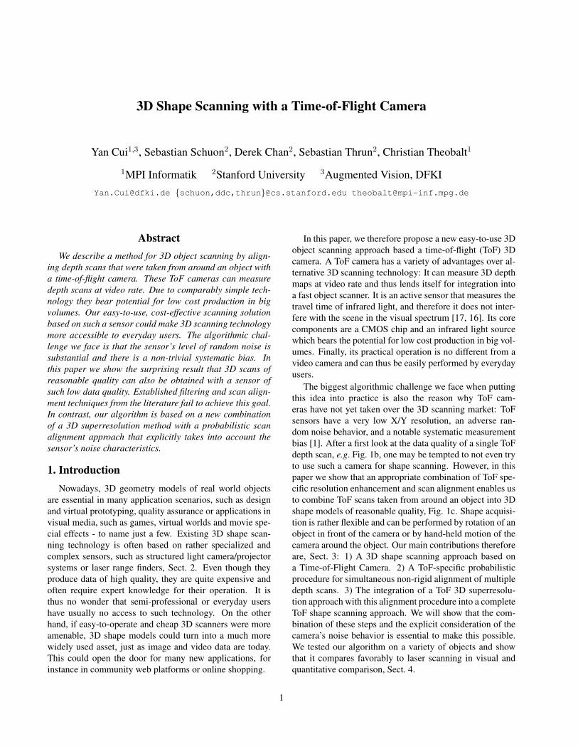
(a) Color Image (b) Raw Scan (c) Proposed Method (d) Laser Scan (e) Error Plot (f) Color Coding Legend
Figure 1: Antique head (a); our algorithm computes a 3D model of reasonable quality (c) despite severe errors in the raw ToFdata (b). Reconstruction error (e) compared to a laser scan (d) shows that no circumstance the error was larger than 2.5 cm,while for most of the surface it was below 1.0 cm.(Note: raw aligned scans, no hole filling done)
2. Related WorkMost commercial systems for 3D shape scanning are
based on structured light projection or laser stripe projec-tion, please refer to [18, 10] for a recent overview. Pas-sive image-based methods have also been successfully usedfor 3D shape reconstruction [24]. To build a complete 3Dmodel, it is commnon to align several scans taken from dif-ferent viewpoints (usually under very controlled motion). Incontrast to ToF cameras, the above mentioned sensors pro-vide rather clean data of relatively low random noise andsystematic error. On such data, local rigid alignment tech-niques, such as Iterative Closest Points (ICP) and its vari-ants [5] or global rigid alignment techniques, e.g. [4, 3, 11]can be used to register the scans against each other. Fi-nally, a scan merging procedure, such as [8] can be appliedto build a single 3D mesh. Hand-held scanners based onthe above technologies have been proposed where the cam-era can be freely moved around an object (or vice versa),e.g. [22]. Our work supports both hand-held scanning andscanning under controlled motion, e.g. with a turntable. Arelated idea to build a relatively simple 3D scanner has beenproposed by Bouguet et al. [6] who measure 3D shape byrecording a shadow cast by a rod moved over the object.However, freely moving the scanner around the object isnot easy with this approach.
So far, time-of-flight (ToF) cameras [17, 16] have rarelybeen explored as sensors for 3D object scanning [12, 25],even though they have a variety of advantages over theabove technologies (see Sect. 3 for details). This is mainlydue to the challenging noise and bias characteristics [1]which renders direct application of established filtering andalignment approaches infeasible. Some previous work pro-poses pre-calibration approaches to compensate for instancebias effects in the cameras [19]. Others tried to attack ToFcamera deficiencies by combining them with normal colorcameras, e.g. [26, 2]. In contrast, in this paper we show
that reliable shape capture is feasible with ToF camerasalone. To this end we capitalize on recent time-of-flightsuperresolution methods [21, 23]. Related to these meth-ods is the method by Kil et al. [14] for 3D superresolutionwith a laser scanner. The former approaches are designedfor the more challenging noise characteristics of ToF cam-eras. In addition, in our algorithm the systematic cameraerror is compensated by a new global non-rigid scan align-ment approach. Some previous work already deals withglobal non-rigid shape alignment [7], but not under consid-eration of ToF specifics. Related to our work is also researchon surface reconstruction from noisy, but already aligned,scans [13, 9]. Our approach differs in that it extends pre-vious work on probabilistic non-rigid alignment of pairs ofscans [20] into a global method. Suitable rigid and non-rigid scan alignment is achieved by explicitly incorporatingToF specific noise characteristics.
3. Our AlgorithmOur goal is to build the, to our knowledge, first 3D shape
scanner based on a Time-of-Flight camera that can be usedin hand-held and turntable scanning mode. We use a MESASwissranger SR4000 as ToF sensor. In a nutshell, it emitsinfrared light into the scene and at each pixel measures thereturn time of the reflected light from which it determinesthe depth of the pixel. More about the phase-shift basedinternal measurement principle of the SR4000 can be found,for instance, in [17, 16].
The time-of-flight sensor has a variety of conceptual ad-vantages over previously used sensor techniques for shapescanning: it captures full frame depth at video rate, i.e. itdoes not need to subsequently scan scene points for a singledepth map (like a laser scanner), it does not rely on timemultiplexing like structured light scanners ( even thoughinternally the ToF camera performs several measurements;for normal motion at normal speed this effect is negligi-
Super-
resolution
Scan
Alignment
Raw Depth DataHigh Resolution
Depth Data
High Resolution
3D Model
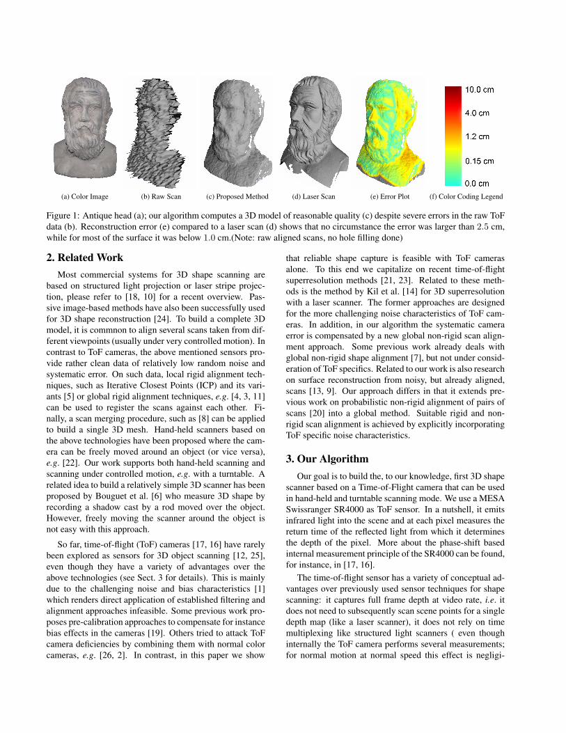
Figure 2: Outline of our processing pipeline.
ble). Additionally, its measurement quality is largely inde-pendent from scene texture and it does not interfere with thescene in the visual spectrum enabling simultaneous texturerecording. Finally, it is based on comparably simple CMOStechnology enabling low cost manufacturing in large num-bers.
During acquisition the camera is either moved by hand inan arc around the object, or the object is turned in front ofthe static camera, e.g. using a turntable. The object shouldstay roughly in the center of the field of view and the dis-tance of the camera to the object is kept approximately con-stant, Fig 3. This way, a sequence of i = 1, . . . , Nc depthmaps Di is obtained from Nc subsequent positions alongthe camera path, each of which can be described by a tupleof a rotation matrix and a translation vector with respect toa global coordinate system (Ri, ti).
Unfortunately, the previously mentioned advantages ofthe ToF sensor come at the price of very low X/Y sensorresolution (Nx = 176×Ny = 144 pixels for the SR4000),random depth noise with significant standard deviation anda substantial systematic measurement bias that distorts thedepth maps [1, 15], see Figs. 1, 2 and 8 for examples of rawToF depth scans. Our new approach presented in this pa-per enables us to combine and align these rather low qual-ity depth scans. The result is a 3D model of substantiallyhigher quality than a single depth scan would suggest. It’salgorithmic core and the main novelty is a combination of3D ToF superresolution with a new ToF-specific probabilis-tic method for simultaneous rigid and non-rigid alignmentof multiple depth scans. Our algorithm comprises the fol-lowing steps, Fig. 2:
1) Initial estimates for the scan poses (Ri, ti) are foundby using the Voodoo camera tracker 1 on the amplitude im-ages provided by the camera for each depth map Di.
2) We subdivide the set of Nc depth images into a set of` = 1, . . . ,K chunks of depth images, Fig. 3. Each chunkC` = (Dρ(`), . . . , Dρ(`)+C) comprises C subsequent depthimages starting from a frame index ρ(`). To each chunkof depth images a ToF superresolution approach is applied,yielding K new depth maps H` with much higher X/Y res-olution, Section 3.1.
3) the H` are converted to 3D geometry Y` and aligned
1Voodo camera tracker: www.digilab.unihannover. de/index.html
by means of a probabilistic alignment approach that notonly recovers the rigid scan alignment parameters, butalso compensates for non-rigid bias-induced deformations,Sects. 3.2 and 3.3. Please note that we don’t perform ex-plicit scan merging, e.g. to build a single surface mesh. Anysurface reconstruction or scan merging strategy from the lit-erature can be applied after our alignment.
3.1. Superresolution
To each chunk of frames C`, we apply the LidarBoostToF superresolution approach [23] which yields a high-resolution depth map aligned to the center frame of thechunk. In the following we briefly describe the core con-cepts of LidarBoost and refer the reader to [23] for moredetail. First, all depth maps in the chunk are aligned to thecenter frame using optical flow. This is sufficiently accu-rate since the maximum viewpoint displacements through-out the entire chunk are typically one to two depth pixels.LidarBoost extracts a high-resolution denoised center depthmap H`, Fig. 2, from the aligned low resolution depth mapby solving an optimization problem of the form:
minH`
Edata(Lρ(`), . . . , Lρ(`)+C , H`) + Ereg(H`) . (1)
Here, Lρ(`), . . . , Lρ(`)+C are the raw depth maps aligned tothe center one. Edata measures the agreement ofH` with thealigned low resolution maps; unreliable depth pixels withlow amplitude are discarded. Ereg is a feature-preservingsmoothing regularizer tailored to ToF data. We upsamplethe depth data by factor 4 in both X and Y resolution. The
Cl
Figure 3: A typical camera path: The dotted segments arethe frame chunks C` from which superresolved depth scansare computed.
H` are straightforwardly converted into 3D point clouds Y`by reprojection into space using the ToF camera’s intrinsicparameters (calibrated off-line).
3.2. Systematic Bias
While the random noise is effectively reduced by the su-perresolution approach, the ToF data’s systematic bias leadsto non-rigid ToF scan distortions and therefore needs spe-cial attention. Let xi, i = 1, . . . , Nx × Ny be a 3D pointmeasured by the depth camera (i.e. the point in space afterreprojection of the depth pixel), and Vi be the the direc-tion of the camera ray towards the point. Then the bias canbe modeled as a systematic offset di along this ray whichmakes the camera measure the value xi = xi + Vidi ratherthan the true 3D point xi (Fig. 4a). Previous studies haveshown that the depth bias is pixel dependent and dependenton many factors, including the camera’s integration time,scene reflectance, surface orientation, and distance [1, 15].
Accounting for all such dependencies in our frameworkwould render the problem intractable. We therefore makea few simplifying assumptions. First, in practice the biasdependency on reflectance, surface orientation, and integra-tion (since it stays constant for a scan) can be neglected.Second, the depth range covered by the scanned object isusually limited and the distance of the camera to the ob-ject remains fairly constant. Therefore, we ignore the depthdependency of the bias. Finally, when averaging hundredsof depth frames of a flat wall, the resulting 3D model typi-cally shows a radially symmetric deviation from the plane,with increasing curvature (bias) the further one is away fromthe depth image center. We therefore assume that all depthpixels with the same radial distance from the image centerhave the same bias, and the bias increases with the radius.Since the H` are computed from closely spaced low reso-lution ToF scans, we assume the above bias characteristicsalso applies to them. The set of radially symmetric bias val-ues therefore is parameterized as (d1, . . . , dO) withO beinghalf the maximum number of pixels on the diagonal of allH`.
3.3. Probabilistic Simultaneous Scan Alignment
The last and most important step of ToF scan recon-struction is a probabilistic global alignment approach thatsolves for the rigid alignment (R`, t`) of all high-resolution3D point clouds Y`, as well as the systematic bias values(d1, . . . , dO). Rather than pre-compensating the bias, asin [15], we explicitly model the set of bias variables as un-knowns of the alignment procedure. This enables us to ac-commodate for the potential scene dependency of the biasto a certain degree while keeping the number of variables inreasonable bounds.
Our algorithm is inspired by the non-rigid registrationapproach for pairs of scans described in [20]. We extend
R,t
VXi · d
X
Picture
Plane
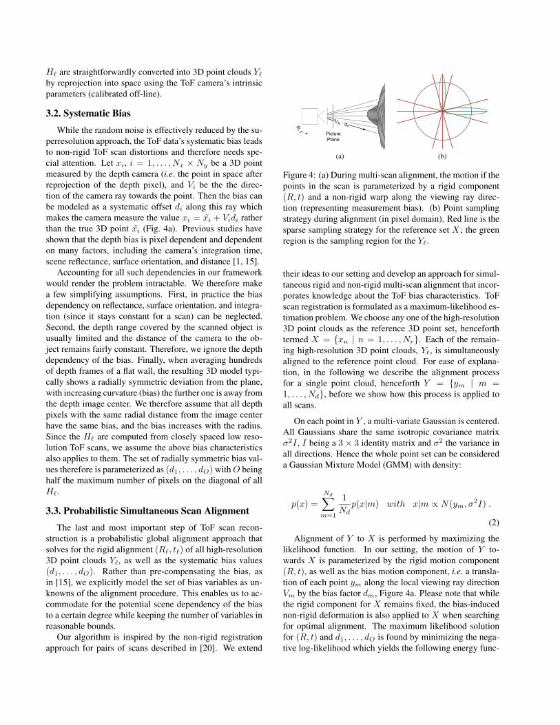
(a) (b)
Figure 4: (a) During multi-scan alignment, the motion if thepoints in the scan is parameterized by a rigid component(R, t) and a non-rigid warp along the viewing ray direc-tion (representing measurement bias). (b) Point samplingstrategy during alignment (in pixel domain). Red line is thesparse sampling strategy for the reference set X; the greenregion is the sampling region for the Y`.
their ideas to our setting and develop an approach for simul-taneous rigid and non-rigid multi-scan alignment that incor-porates knowledge about the ToF bias characteristics. ToFscan registration is formulated as a maximum-likelihood es-timation problem. We choose any one of the high-resolution3D point clouds as the reference 3D point set, henceforthtermed X = {xn | n = 1, . . . , Nr}. Each of the remain-ing high-resolution 3D point clouds, Y`, is simultaneouslyaligned to the reference point cloud. For ease of explana-tion, in the following we describe the alignment processfor a single point cloud, henceforth Y = {ym | m =1, . . . , Nd}, before we show how this process is applied toall scans.
On each point in Y , a multi-variate Gaussian is centered.All Gaussians share the same isotropic covariance matrixσ2I , I being a 3 × 3 identity matrix and σ2 the variance inall directions. Hence the whole point set can be considereda Gaussian Mixture Model (GMM) with density:
p(x) =Nd∑m=1
1Nd
p(x|m) with x|m ∝ N(ym, σ2I) .
(2)
Alignment of Y to X is performed by maximizing thelikelihood function. In our setting, the motion of Y to-wards X is parameterized by the rigid motion component(R, t), as well as the bias motion component, i.e. a transla-tion of each point ym along the local viewing ray directionVm by the bias factor dm, Figure 4a. Please note that whilethe rigid component for X remains fixed, the bias-inducednon-rigid deformation is also applied to X when searchingfor optimal alignment. The maximum likelihood solutionfor (R, t) and d1, . . . , dO is found by minimizing the nega-tive log-likelihood which yields the following energy func-
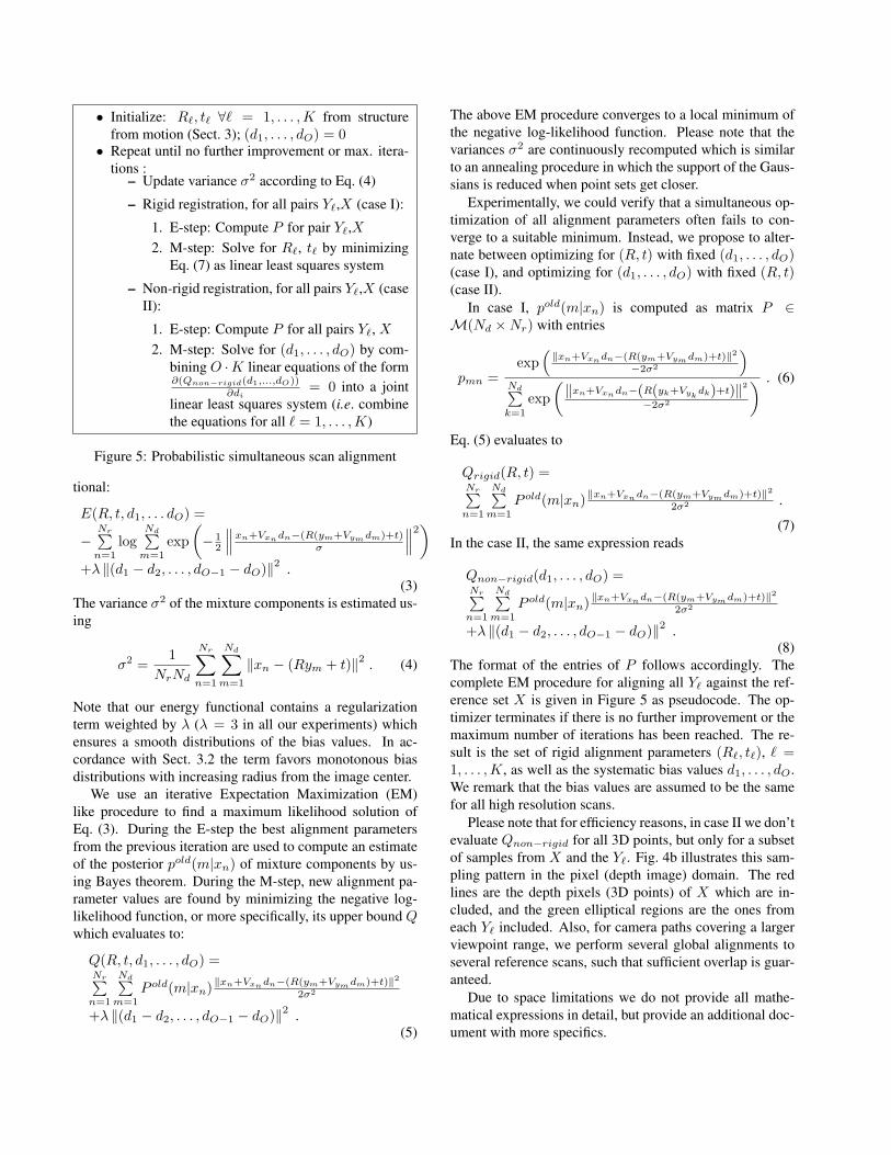
• Initialize: R`, t` ∀` = 1, . . . ,K from structurefrom motion (Sect. 3); (d1, . . . , dO) = 0• Repeat until no further improvement or max. itera-
tions :– Update variance σ2 according to Eq. (4)
– Rigid registration, for all pairs Y`,X (case I):
1. E-step: Compute P for pair Y`,X2. M-step: Solve for R`, t` by minimizing
Eq. (7) as linear least squares system
– Non-rigid registration, for all pairs Y`,X (caseII):
1. E-step: Compute P for all pairs Y`, X2. M-step: Solve for (d1, . . . , dO) by com-
bining O ·K linear equations of the form∂(Qnon−rigid(d1,...,dO))
∂di= 0 into a joint
linear least squares system (i.e. combinethe equations for all ` = 1, . . . ,K)
Figure 5: Probabilistic simultaneous scan alignment
tional:
E(R, t, d1, . . . dO) =
−Nr∑n=1
logNd∑m=1
exp(− 1
2
∥∥∥xn+Vxndn−(R(ym+Vymdm)+t)σ
∥∥∥2)
+λ ‖(d1 − d2, . . . , dO−1 − dO)‖2 .(3)
The variance σ2 of the mixture components is estimated us-ing
σ2 =1
NrNd
Nr∑n=1
Nd∑m=1
‖xn − (Rym + t)‖2 . (4)
Note that our energy functional contains a regularizationterm weighted by λ (λ = 3 in all our experiments) whichensures a smooth distributions of the bias values. In ac-cordance with Sect. 3.2 the term favors monotonous biasdistributions with increasing radius from the image center.
We use an iterative Expectation Maximization (EM)like procedure to find a maximum likelihood solution ofEq. (3). During the E-step the best alignment parametersfrom the previous iteration are used to compute an estimateof the posterior pold(m|xn) of mixture components by us-ing Bayes theorem. During the M-step, new alignment pa-rameter values are found by minimizing the negative log-likelihood function, or more specifically, its upper bound Qwhich evaluates to:
Q(R, t, d1, . . . , dO) =Nr∑n=1
Nd∑m=1
P old(m|xn)‖xn+Vxndn−(R(ym+Vymdm)+t)‖22σ2
+λ ‖(d1 − d2, . . . , dO−1 − dO)‖2 .(5)
The above EM procedure converges to a local minimum ofthe negative log-likelihood function. Please note that thevariances σ2 are continuously recomputed which is similarto an annealing procedure in which the support of the Gaus-sians is reduced when point sets get closer.
Experimentally, we could verify that a simultaneous op-timization of all alignment parameters often fails to con-verge to a suitable minimum. Instead, we propose to alter-nate between optimizing for (R, t) with fixed (d1, . . . , dO)(case I), and optimizing for (d1, . . . , dO) with fixed (R, t)(case II).
In case I, pold(m|xn) is computed as matrix P ∈M(Nd ×Nr) with entries
pmn =exp
(‖xn+Vxndn−(R(ym+Vymdm)+t)‖2
−2σ2
)Nd∑k=1
exp(‖xn+Vxndn−(R(yk+Vyk
dk)+t)‖2−2σ2
) . (6)
Eq. (5) evaluates to
Qrigid(R, t) =Nr∑n=1
Nd∑m=1
P old(m|xn)‖xn+Vxndn−(R(ym+Vymdm)+t)‖22σ2 .
(7)In the case II, the same expression reads
Qnon−rigid(d1, . . . , dO) =Nr∑n=1
Nd∑m=1
P old(m|xn)‖xn+Vxndn−(R(ym+Vymdm)+t)‖22σ2
+λ ‖(d1 − d2, . . . , dO−1 − dO)‖2 .(8)
The format of the entries of P follows accordingly. Thecomplete EM procedure for aligning all Y` against the ref-erence set X is given in Figure 5 as pseudocode. The op-timizer terminates if there is no further improvement or themaximum number of iterations has been reached. The re-sult is the set of rigid alignment parameters (R`, t`), ` =1, . . . ,K, as well as the systematic bias values d1, . . . , dO.We remark that the bias values are assumed to be the samefor all high resolution scans.
Please note that for efficiency reasons, in case II we don’tevaluate Qnon−rigid for all 3D points, but only for a subsetof samples from X and the Y`. Fig. 4b illustrates this sam-pling pattern in the pixel (depth image) domain. The redlines are the depth pixels (3D points) of X which are in-cluded, and the green elliptical regions are the ones fromeach Y` included. Also, for camera paths covering a largerviewpoint range, we perform several global alignments toseveral reference scans, such that sufficient overlap is guar-anteed.
Due to space limitations we do not provide all mathe-matical expressions in detail, but provide an additional doc-ument with more specifics.
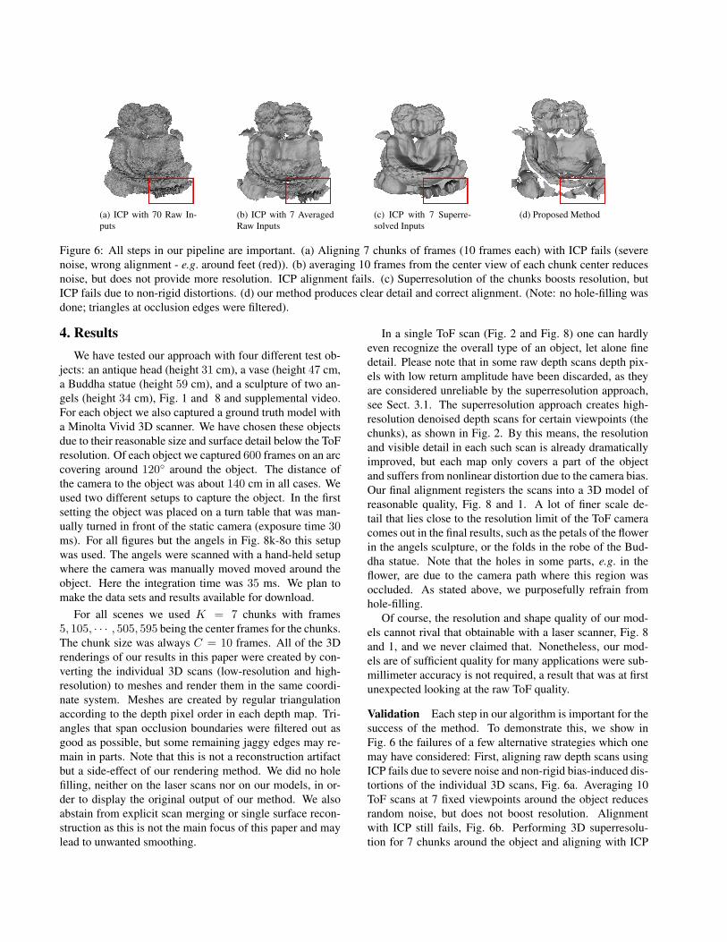
(a) ICP with 70 Raw In-puts
(b) ICP with 7 AveragedRaw Inputs
(c) ICP with 7 Superre-solved Inputs
(d) Proposed Method
Figure 6: All steps in our pipeline are important. (a) Aligning 7 chunks of frames (10 frames each) with ICP fails (severenoise, wrong alignment - e.g. around feet (red)). (b) averaging 10 frames from the center view of each chunk center reducesnoise, but does not provide more resolution. ICP alignment fails. (c) Superresolution of the chunks boosts resolution, butICP fails due to non-rigid distortions. (d) our method produces clear detail and correct alignment. (Note: no hole-filling wasdone; triangles at occlusion edges were filtered).
4. ResultsWe have tested our approach with four different test ob-
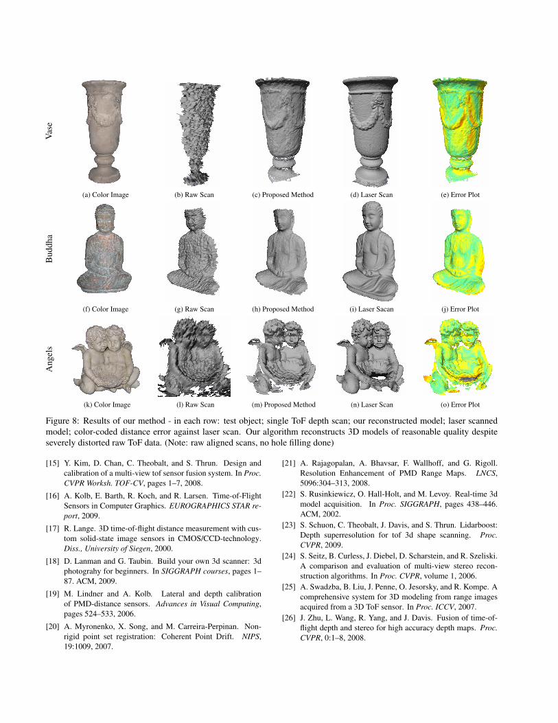
jects: an antique head (height 31 cm), a vase (height 47 cm,a Buddha statue (height 59 cm), and a sculpture of two an-gels (height 34 cm), Fig. 1 and 8 and supplemental video.For each object we also captured a ground truth model witha Minolta Vivid 3D scanner. We have chosen these objectsdue to their reasonable size and surface detail below the ToFresolution. Of each object we captured 600 frames on an arccovering around 120◦ around the object. The distance ofthe camera to the object was about 140 cm in all cases. Weused two different setups to capture the object. In the firstsetting the object was placed on a turn table that was man-ually turned in front of the static camera (exposure time 30ms). For all figures but the angels in Fig. 8k-8o this setupwas used. The angels were scanned with a hand-held setupwhere the camera was manually moved moved around theobject. Here the integration time was 35 ms. We plan tomake the data sets and results available for download.
For all scenes we used K = 7 chunks with frames5, 105, · · · , 505, 595 being the center frames for the chunks.The chunk size was always C = 10 frames. All of the 3Drenderings of our results in this paper were created by con-verting the individual 3D scans (low-resolution and high-resolution) to meshes and render them in the same coordi-nate system. Meshes are created by regular triangulationaccording to the depth pixel order in each depth map. Tri-angles that span occlusion boundaries were filtered out asgood as possible, but some remaining jaggy edges may re-main in parts. Note that this is not a reconstruction artifactbut a side-effect of our rendering method. We did no holefilling, neither on the laser scans nor on our models, in or-der to display the original output of our method. We alsoabstain from explicit scan merging or single surface recon-struction as this is not the main focus of this paper and maylead to unwanted smoothing.
In a single ToF scan (Fig. 2 and Fig. 8) one can hardlyeven recognize the overall type of an object, let alone finedetail. Please note that in some raw depth scans depth pix-els with low return amplitude have been discarded, as theyare considered unreliable by the superresolution approach,see Sect. 3.1. The superresolution approach creates high-resolution denoised depth scans for certain viewpoints (thechunks), as shown in Fig. 2. By this means, the resolutionand visible detail in each such scan is already dramaticallyimproved, but each map only covers a part of the objectand suffers from nonlinear distortion due to the camera bias.Our final alignment registers the scans into a 3D model ofreasonable quality, Fig. 8 and 1. A lot of finer scale de-tail that lies close to the resolution limit of the ToF cameracomes out in the final results, such as the petals of the flowerin the angels sculpture, or the folds in the robe of the Bud-dha statue. Note that the holes in some parts, e.g. in theflower, are due to the camera path where this region wasoccluded. As stated above, we purposefully refrain fromhole-filling.
Of course, the resolution and shape quality of our mod-els cannot rival that obtainable with a laser scanner, Fig. 8and 1, and we never claimed that. Nonetheless, our mod-els are of sufficient quality for many applications were sub-millimeter accuracy is not required, a result that was at firstunexpected looking at the raw ToF quality.
Validation Each step in our algorithm is important for thesuccess of the method. To demonstrate this, we show inFig. 6 the failures of a few alternative strategies which onemay have considered: First, aligning raw depth scans usingICP fails due to severe noise and non-rigid bias-induced dis-tortions of the individual 3D scans, Fig. 6a. Averaging 10ToF scans at 7 fixed viewpoints around the object reducesrandom noise, but does not boost resolution. Alignmentwith ICP still fails, Fig. 6b. Performing 3D superresolu-tion for 7 chunks around the object and aligning with ICP
boost detail, but still fails to align the scans properly as vis-ible by the multiple layers of geometry in the arms, Fig. 6c.This is due to the fact that the systematic bias also non-rigidly distorts the superresolved geometry. In contrast, thecombination of ToF 3D superresolution and our new prob-abilistic scan alignment produces correctly aligned resultswith clearly visible detail, Fig. 6d.
We also quantitatively measured the reconstruction qual-ity against the laser scanned ground truth. As one can seein the color-coded reconstruction error renderings in Fig. 8and 1 our models compare very favorably. In most areas theerror is below 1.0 cm, and there are only a few outliers. Inthe figures, areas where there is no ground truth geometryin the laser scan (e.g. holes due to occlusion) are renderedin grey.
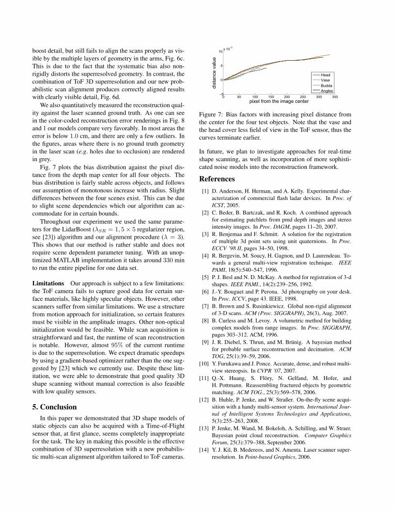
Fig. 7 plots the bias distribution against the pixel dis-tance from the depth map center for all four objects. Thebias distribution is fairly stable across objects, and followsour assumption of monotonous increase with radius. Slightdifferences between the four scenes exist. This can be dueto slight scene dependencies which our algorithm can ac-commodate for in certain bounds.
Throughout our experiment we used the same parame-ters for the LidarBoost (λSR = 1, 5 × 5 regularizer region,see [23]) algorithm and our alignment procedure (λ = 3).This shows that our method is rather stable and does notrequire scene dependent parameter tuning. With an unop-timized MATLAB implementation it takes around 330 minto run the entire pipeline for one data set.
Limitations Our approach is subject to a few limitations:the ToF camera fails to capture good data for certain sur-face materials, like highly specular objects. However, otherscanners suffer from similar limitations. We use a structurefrom motion approach for initialization, so certain featuresmust be visible in the amplitude images. Other non-opticalinitialization would be feasible. While scan acquisition isstraightforward and fast, the runtime of scan reconstructionis notable. However, almost 95% of the current runtimeis due to the superresolution. We expect dramatic speedupsby using a gradient-based optimizer rather than the one sug-gested by [23] which we currently use. Despite these lim-itation, we were able to demonstrate that good quality 3Dshape scanning without manual correction is also feasiblewith low quality sensors.
5. ConclusionIn this paper we demonstrated that 3D shape models of
static objects can also be acquired with a Time-of-Flightsensor that, at first glance, seems completely inappropriatefor the task. The key in making this possible is the effectivecombination of 3D superresolution with a new probabilis-tic multi-scan alignment algorithm tailored to ToF cameras.
0 50 100 150 200 250 300 350−5
0
5
10x 10
−3
pixel from the image center
distancevalue
Head
Vase
Budda
Angles
Figure 7: Bias factors with increasing pixel distance fromthe center for the four test objects. Note that the vase andthe head cover less field of view in the ToF sensor, thus thecurves terminate earlier.
In future, we plan to investigate approaches for real-timeshape scanning, as well as incorporation of more sophisti-cated noise models into the reconstruction framework.
References[1] D. Anderson, H. Herman, and A. Kelly. Experimental char-
acterization of commercial flash ladar devices. In Proc. ofICST, 2005.
[2] C. Beder, B. Bartczak, and R. Koch. A combined approachfor estimating patchlets from pmd depth images and stereointensity images. In Proc. DAGM, pages 11–20, 2007.
[3] R. Benjemaa and F. Schmitt. A solution for the registrationof multiple 3d point sets using unit quaternions. In Proc.ECCV ’98 II, pages 34–50, 1998.
[4] R. Bergevin, M. Soucy, H. Gagnon, and D. Laurendeau. To-wards a general multi-view registration technique. IEEEPAMI, 18(5):540–547, 1996.
[5] P. J. Besl and N. D. McKay. A method for registration of 3-dshapes. IEEE PAMI., 14(2):239–256, 1992.
[6] J.-Y. Bouguet and P. Perona. 3d photography on your desk.In Proc. ICCV, page 43. IEEE, 1998.
[7] B. Brown and S. Rusinkiewicz. Global non-rigid alignmentof 3-D scans. ACM (Proc. SIGGRAPH), 26(3), Aug. 2007.
[8] B. Curless and M. Levoy. A volumetric method for buildingcomplex models from range images. In Proc. SIGGRAPH,pages 303–312. ACM, 1996.
[9] J. R. Diebel, S. Thrun, and M. Brunig. A bayesian methodfor probable surface reconstruction and decimation. ACMTOG, 25(1):39–59, 2006.
[10] Y. Furukawa and J. Ponce. Accurate, dense, and robust multi-view stereopsis. In CVPR ’07, 2007.
[11] Q.-X. Huang, S. Flory, N. Gelfand, M. Hofer, andH. Pottmann. Reassembling fractured objects by geometricmatching. ACM TOG., 25(3):569–578, 2006.
[12] B. Huhle, P. Jenke, and W. Straßer. On-the-fly scene acqui-sition with a handy multi-sensor system. International Jour-nal of Intelligent Systems Technologies and Applications,5(3):255–263, 2008.
[13] P. Jenke, M. Wand, M. Bokeloh, A. Schilling, and W. Straer.Bayesian point cloud reconstruction. Computer GraphicsForum, 25(3):379–388, September 2006.
[14] Y. J. Kil, B. Medereos, and N. Amenta. Laser scanner super-resolution. In Point-based Graphics, 2006.
Vas
e
(a) Color Image (b) Raw Scan (c) Proposed Method (d) Laser Scan (e) Error Plot
Bud
dha
(f) Color Image (g) Raw Scan (h) Proposed Method (i) Laser Sacan (j) Error Plot
Ang
els
(k) Color Image (l) Raw Scan (m) Proposed Method (n) Laser Scan (o) Error Plot
Figure 8: Results of our method - in each row: test object; single ToF depth scan; our reconstructed model; laser scannedmodel; color-coded distance error against laser scan. Our algorithm reconstructs 3D models of reasonable quality despiteseverely distorted raw ToF data. (Note: raw aligned scans, no hole filling done)
[15] Y. Kim, D. Chan, C. Theobalt, and S. Thrun. Design andcalibration of a multi-view tof sensor fusion system. In Proc.CVPR Worksh. TOF-CV, pages 1–7, 2008.
[16] A. Kolb, E. Barth, R. Koch, and R. Larsen. Time-of-FlightSensors in Computer Graphics. EUROGRAPHICS STAR re-port, 2009.
[17] R. Lange. 3D time-of-flight distance measurement with cus-tom solid-state image sensors in CMOS/CCD-technology.Diss., University of Siegen, 2000.
[18] D. Lanman and G. Taubin. Build your own 3d scanner: 3dphotograhy for beginners. In SIGGRAPH courses, pages 1–87. ACM, 2009.
[19] M. Lindner and A. Kolb. Lateral and depth calibrationof PMD-distance sensors. Advances in Visual Computing,pages 524–533, 2006.
[20] A. Myronenko, X. Song, and M. Carreira-Perpinan. Non-rigid point set registration: Coherent Point Drift. NIPS,19:1009, 2007.
[21] A. Rajagopalan, A. Bhavsar, F. Wallhoff, and G. Rigoll.Resolution Enhancement of PMD Range Maps. LNCS,5096:304–313, 2008.
[22] S. Rusinkiewicz, O. Hall-Holt, and M. Levoy. Real-time 3dmodel acquisition. In Proc. SIGGRAPH, pages 438–446.ACM, 2002.
[23] S. Schuon, C. Theobalt, J. Davis, and S. Thrun. Lidarboost:Depth superresolution for tof 3d shape scanning. Proc.CVPR, 2009.
[24] S. Seitz, B. Curless, J. Diebel, D. Scharstein, and R. Szeliski.A comparison and evaluation of multi-view stereo recon-struction algorithms. In Proc. CVPR, volume 1, 2006.
[25] A. Swadzba, B. Liu, J. Penne, O. Jesorsky, and R. Kompe. Acomprehensive system for 3D modeling from range imagesacquired from a 3D ToF sensor. In Proc. ICCV, 2007.
[26] J. Zhu, L. Wang, R. Yang, and J. Davis. Fusion of time-of-flight depth and stereo for high accuracy depth maps. Proc.CVPR, 0:1–8, 2008.