Embed Size (px)
Citation preview
3D Reconstruction of Interior Wall Surfaces Under Occlusion and Clutter
Antonio AdanDepartment of Electrical Engineering,
Electronics, and AutomationCastilla La Mancha University
Ciudad Real, [email protected]
Daniel HuberThe Robotics Institute
Carnegie Mellon UniversityPittsburgh, Pennsylvania, USA
Abstract—Laser scanners are often used to create 3D modelsof buildings for civil engineering applications. The currentmanual process is time-consuming and error-prone. This paperpresents a method for using laser scanner data to modelpredominantly planar surfaces, such as walls, floors, andceilings, despite the presence of significant amounts of clut-ter and occlusion, which occur frequently in natural indoorenvironments. Our goal is to recover the surface shape, detectand model any openings, and fill in the occluded regions.Our method identifies candidate surfaces for modeling, labelsoccluded surface regions, detects openings in each surfaceusing supervised learning, and reconstructs the surface in theoccluded regions. We evaluate the method on a large, highlycluttered data set of a building consisting of forty separaterooms.
Keywords-3D model, laser scanner, point cloud, openingdetection, occlusion reasoning
I. INTRODUCTION
Laser scanners are increasingly being used to create 3Dmodels of buildings and other facilities in the architecture,engineering, and construction (AEC) domain for a varietyof purposes, including building renovation, cultural heritagepreservation, and facility management [5], [12]. These mod-els are usually manually constructed – a labor-intensive andtedious process. Our long-term goal is to develop methodsto automate this process using computer vision and machinelearning techniques (Figure 1).
While there has been much research on mapping andmodeling of building interiors and exteriors using robots [8],aerial platforms [25], and terrestrial laser scanners [10], rela-tively little attention has been given to the detailed modelingof wall surfaces [2], [18]. Exterior facade modeling methodsoperate under the assumption that the surface being modeledis relatively unobstructed. In indoor environments, objectslike furniture and wallhangings, frequently occlude the wallsurfaces, making the modeling problem more challenging. Inthis paper, we address the problem of detailed modeling ofwall surfaces in natural, cluttered environments. Our goal isto recover the wall surface, to identify and model openings,such as windows and doorways, and to fill occluded surfaceregions.
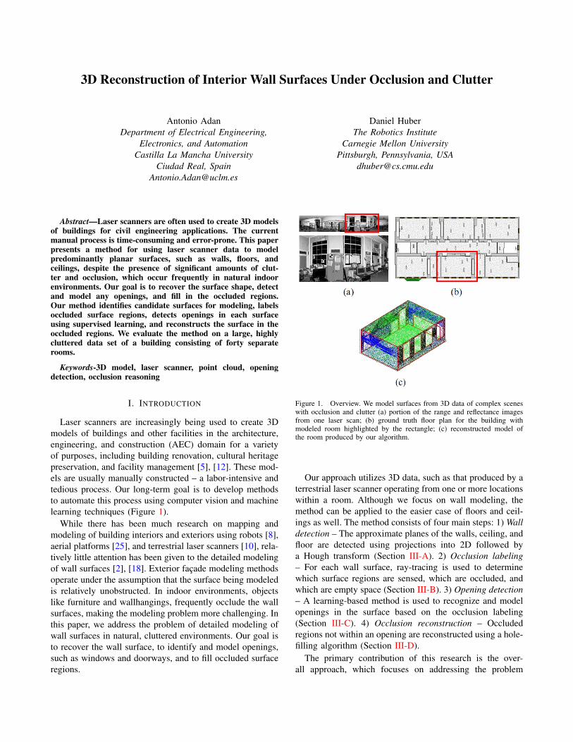
Figure 1. Overview. We model surfaces from 3D data of complex sceneswith occlusion and clutter (a) portion of the range and reflectance imagesfrom one laser scan; (b) ground truth floor plan for the building withmodeled room highlighted by the rectangle; (c) reconstructed model ofthe room produced by our algorithm.
Our approach utilizes 3D data, such as that produced by aterrestrial laser scanner operating from one or more locationswithin a room. Although we focus on wall modeling, themethod can be applied to the easier case of floors and ceil-ings as well. The method consists of four main steps: 1) Walldetection – The approximate planes of the walls, ceiling, andfloor are detected using projections into 2D followed bya Hough transform (Section III-A). 2) Occlusion labeling– For each wall surface, ray-tracing is used to determinewhich surface regions are sensed, which are occluded, andwhich are empty space (Section III-B). 3) Opening detection– A learning-based method is used to recognize and modelopenings in the surface based on the occlusion labeling(Section III-C). 4) Occlusion reconstruction – Occludedregions not within an opening are reconstructed using a hole-filling algorithm (Section III-D).
The primary contribution of this research is the over-all approach, which focuses on addressing the problem
of clutter and occlusions and explicitly reasons about themissing information. Our approach is unique in that it distin-guishes between missing data from occlusion versus missingdata in an opening in the wall. Secondly, we propose alearning-based method for detecting and modeling openingsand distinguishing them from similarly shaped occludedregions. Finally, we propose and use methods for objectivelyevaluating reconstruction accuracy, whereas previous facademodeling work has focused on primarily on subjective visualquality.
II. RELATED WORK
There is a large body of research on reconstruction ofbuilding interiors and exteriors using laser scanners [1]–[4], [10], [13], [18], [19], [23], [24] as well as imageryand video [6], [17]. Much of the emphasis in previouswork has been on creating visually realistic models ratherthan geometrically accurate ones. Examples in this categoryinclude methods by El-Hakim et al., which focused onindoor environments [9], and Frueh et al., which focusedon outdoor environments [10].
Image- and video-based approaches for modeling build-ings are also well established. Early work by Debevec usedimages to semi-automatically model building exteriors [6].More recently, Pollefeys et al. used video to model urbanenvironments from a moving vehicle [17]. So far, theseapproaches are not accurate enough for the AEC domain,but recent advances, such as Manhattan world stereo [11],show promise.
As laser scanner technology has progressed, researchershave begun using these devices to construct detailed modelsof walls and building facades. Thrun et al. developed a planeextraction method based on the expectation-maximizationalgorithm [24], and other researchers have proposed planesweep approaches to find planar regions [4], [13]. Stamos etal. combine planar patch modeling with meshes in complexareas [23]. Some facade modeling methods also extractwindow openings, which are normally detected based onregions where the data density is zero or very low and thenmodeled using rectangles [3], [18]. Model-based approachescan also be used to predict patterns in facades using top-down processing [1], [19].
Occlusions sometimes occur in facade reconstruction(e.g., by trees, parked cars, etc.), but most existing workassumes that occluded regions can be observed from anotherviewpoint [10], [18]. Such methods would not work in situ-ations with significant, unavoidable occlusions or windowswith objects on or in them (e.g., air-conditioners, pictures,etc.). An alternative approach is to identify another regionon a facade that matches the occluded region and substitutethe missing data with the observed data [2], [26]. The moregeneral problem of reconstructing occluded surfaces in 3Dis also known as hole filling or surface completion, and thereare many proposed solutions [5], [21]. Surfaces in buildings
often have a more constrained structure, and, consequently,specialized approaches can be applied in many cases [7],[10], [16], [22].
One key distinction between our proposed method andprevious work is that our method is explicitly reasons aboutocclusions and is therefore capable of operating in natural,heavily occluded environments. In contrast, methods such asBudroni’s do not consider the occlusion [4]. In that work,and in other previous work (e.g., [13], [24]), the test dataconsists of hallways with no furniture or other potentiallyoccluding objects. In our data, on average, only 50% ofthe wall surface area was observed (see Section IV), andprevious methods would likely perform poorly in the facethese occlusion levels.
III. WALL SURFACE MODELING AND RECONSTRUCTION
Our wall surface modeling algorithm uses 3D data ob-tained from fixed, known locations throughout a facility.The data from one location is known as a scan. We assumethe scans are already registered (i.e., aligned in a commoncoordinate system), and that the “up” direction is known.Data registration is a well-studied problem, and methods tomanually or automatically register scans are commerciallyavailable.
Laser scanners produce enormous data sets – our test datacontains over 500 million points. To cope with this quantityof data, we adopt a voxel-based scheme for the algorithm’searly stages. We denote the space of 3D points P and theoverlaid space of voxels as V. Each point pi in the set of3D points P is quantized into a voxel in V, and the centersof the occupied voxels form a new, sparser set of pointsV. We implicitly assume that the walls are aligned with anaxis of V, but it is straightforward to define separate voxelspaces for each wall being modeled. We also assume thatthe surfaces to be modeled are planar. The extension to non-planar surfaces is the subject of ongoing work. The nextseveral sub-sections detail the steps of our algorithm.
A. Wall Detection
The first step in our algorithm is to detect and estimatethe surfaces to be modeled. This detection is performed bya method similar to that described in [15]. The modes of ahistogram of height values zi of each point vi in V determinethe height of the ceiling and floor. Similarly, projectingthe points’ horizontal coordinates (xi, yi) onto a horizontalplane gives a 2D histogram from which wall surfaces areextracted using a Hough transform (Figure 2). The result isa set of surfaces S to be further processed. Each surfaceSj ∈ S is modeled by the set of voxels bounded by arectangle encompassing the occupied voxels used to definethe surface plane. Note that Sj can be treated as a 2D imageIj by projecting orthographically along the normal direction.The remaining steps in the algorithm operate on each surfaceSj ∈ S individually.
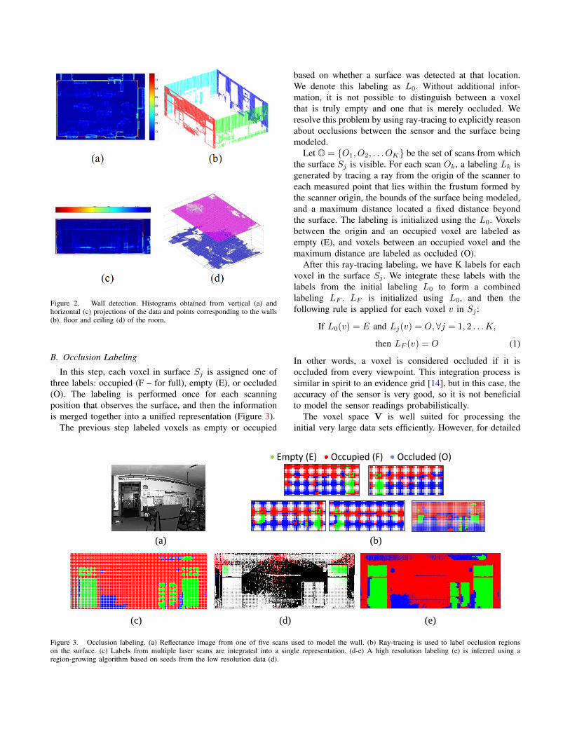
Figure 2. Wall detection. Histograms obtained from vertical (a) andhorizontal (c) projections of the data and points corresponding to the walls(b), floor and ceiling (d) of the room.
B. Occlusion Labeling
In this step, each voxel in surface Sj is assigned one ofthree labels: occupied (F – for full), empty (E), or occluded(O). The labeling is performed once for each scanningposition that observes the surface, and then the informationis merged together into a unified representation (Figure 3).
The previous step labeled voxels as empty or occupied
based on whether a surface was detected at that location.We denote this labeling as L0. Without additional infor-mation, it is not possible to distinguish between a voxelthat is truly empty and one that is merely occluded. Weresolve this problem by using ray-tracing to explicitly reasonabout occlusions between the sensor and the surface beingmodeled.
Let O = {O1, O2, . . . OK} be the set of scans from whichthe surface Sj is visible. For each scan Ok, a labeling Lk isgenerated by tracing a ray from the origin of the scanner toeach measured point that lies within the frustum formed bythe scanner origin, the bounds of the surface being modeled,and a maximum distance located a fixed distance beyondthe surface. The labeling is initialized using the L0. Voxelsbetween the origin and an occupied voxel are labeled asempty (E), and voxels between an occupied voxel and themaximum distance are labeled as occluded (O).
After this ray-tracing labeling, we have K labels for eachvoxel in the surface Sj . We integrate these labels with thelabels from the initial labeling L0 to form a combinedlabeling LF . LF is initialized using L0, and then thefollowing rule is applied for each voxel v in Sj :
If L0(v) = E and Lj(v) = O,∀j = 1, 2 . . .K,
then LF (v) = O (1)
In other words, a voxel is considered occluded if it isoccluded from every viewpoint. This integration process issimilar in spirit to an evidence grid [14], but in this case, theaccuracy of the sensor is very good, so it is not beneficialto model the sensor readings probabilistically.
The voxel space V is well suited for processing theinitial very large data sets efficiently. However, for detailed
(a) (b)
(c) (d) (e)
Empty (E) Occupied (F) Occluded (O)
Figure 3. Occlusion labeling. (a) Reflectance image from one of five scans used to model the wall. (b) Ray-tracing is used to label occlusion regionson the surface. (c) Labels from multiple laser scans are integrated into a single representation. (d-e) A high resolution labeling (e) is inferred using aregion-growing algorithm based on seeds from the low resolution data (d).
Opening Occupied Occluded
(b) (c)
(d) (e) (f)
(a)
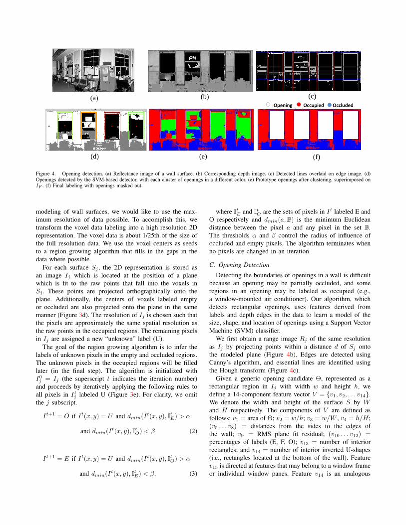
Figure 4. Opening detection. (a) Reflectance image of a wall surface. (b) Corresponding depth image. (c) Detected lines overlaid on edge image. (d)Openings detected by the SVM-based detector, with each cluster of openings in a different color. (e) Prototype openings after clustering, superimposed onIF . (f) Final labeling with openings masked out.
modeling of wall surfaces, we would like to use the max-imum resolution of data possible. To accomplish this, wetransform the voxel data labeling into a high resolution 2Drepresentation. The voxel data is about 1/25th of the size ofthe full resolution data. We use the voxel centers as seedsto a region growing algorithm that fills in the gaps in thedata where possible.
For each surface Sj , the 2D representation is stored asan image Ij which is located at the position of a planewhich is fit to the raw points that fall into the voxels inSj . These points are projected orthographically onto theplane. Additionally, the centers of voxels labeled emptyor occluded are also projected onto the plane in the samemanner (Figure 3d). The resolution of Ij is chosen such thatthe pixels are approximately the same spatial resolution asthe raw points in the occupied regions. The remaining pixelsin Ij are assigned a new “unknown” label (U).
The goal of the region growing algorithm is to infer thelabels of unknown pixels in the empty and occluded regions.The unknown pixels in the occupied regions will be filledlater (in the final step). The algorithm is initialized withI0j = Ij (the superscript t indicates the iteration number)and proceeds by iteratively applying the following rules toall pixels in Itj labeled U (Figure 3e). For clarity, we omitthe j subscript.
It+1 = O if It(x, y) = U and dmin(It(x, y), ItE) > α
and dmin(It(x, y), ItO) < β (2)
It+1 = E if It(x, y) = U and dmin(It(x, y), ItO) > α
and dmin(It(x, y), ItE) < β, (3)
where ItE and ItO are the sets of pixels in It labeled E andO respectively and dmin(a,B) is the minimum Euclideandistance between the pixel a and any pixel in the set B.The thresholds α and β control the radius of influence ofoccluded and empty pixels. The algorithm terminates whenno pixels are changed in an iteration.
C. Opening Detection
Detecting the boundaries of openings in a wall is difficultbecause an opening may be partially occluded, and someregions in an opening may be labeled as occupied (e.g.,a window-mounted air conditioner). Our algorithm, whichdetects rectangular openings, uses features derived fromlabels and depth edges in the data to learn a model of thesize, shape, and location of openings using a Support VectorMachine (SVM) classifier.
We first obtain a range image Rj of the same resolutionas Ij by projecting points within a distance d of Sj ontothe modeled plane (Figure 4b). Edges are detected usingCanny’s algorithm, and essential lines are identified usingthe Hough transform (Figure 4c).
Given a generic opening candidate Θ, represented as arectangular region in Ij with width w and height h, wedefine a 14-component feature vector V = {v1, v2, . . . v14}.We denote the width and height of the surface S by Wand H respectively. The components of V are defined asfollows: v1 = area of Θ; v2 = w/h; v3 = w/W , v4 = h/H;(v5 . . . v8) = distances from the sides to the edges ofthe wall; v9 = RMS plane fit residual; (v10 . . . v12) =percentages of labels (E, F, O); v13 = number of interiorrectangles; and v14 = number of interior inverted U-shapes(i.e., rectangles located at the bottom of the wall). Featurev13 is directed at features that may belong to a window frameor individual window panes. Feature v14 is an analogous
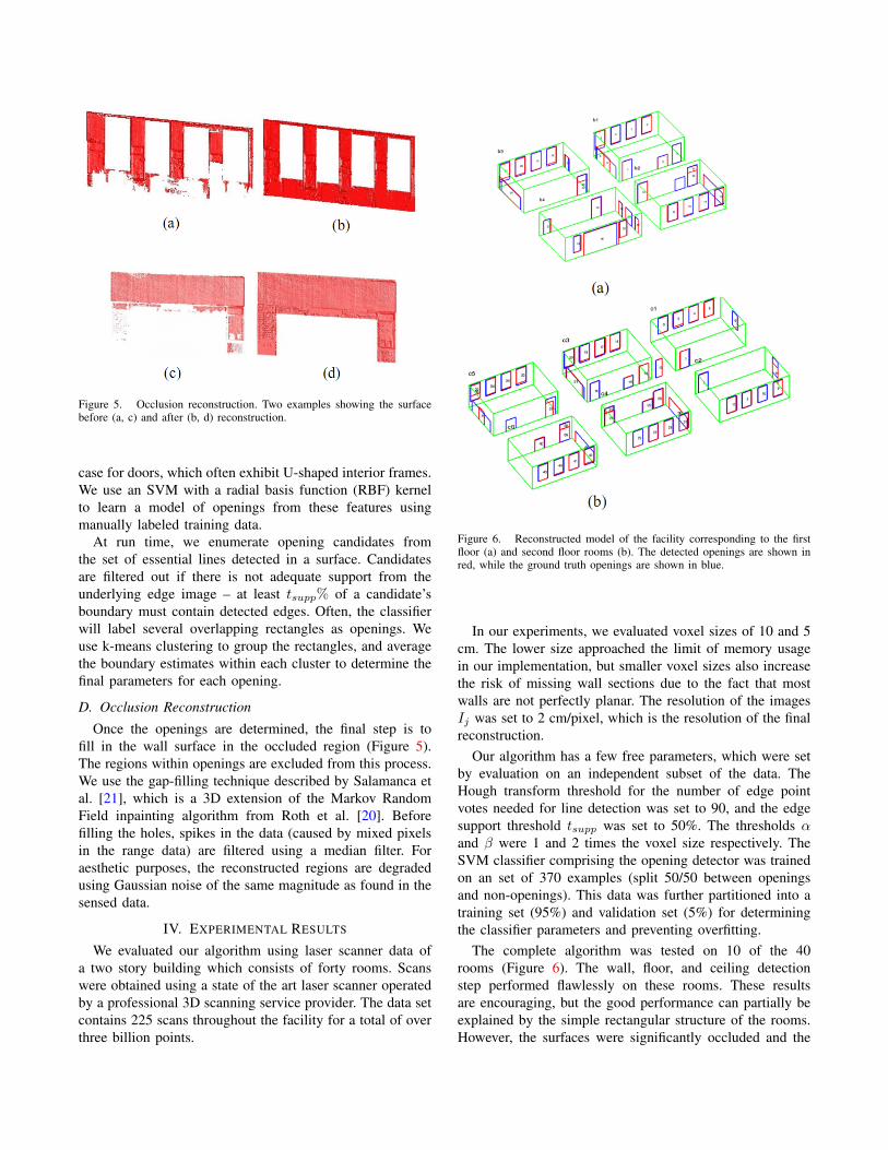
Figure 5. Occlusion reconstruction. Two examples showing the surfacebefore (a, c) and after (b, d) reconstruction.
case for doors, which often exhibit U-shaped interior frames.We use an SVM with a radial basis function (RBF) kernelto learn a model of openings from these features usingmanually labeled training data.
At run time, we enumerate opening candidates fromthe set of essential lines detected in a surface. Candidatesare filtered out if there is not adequate support from theunderlying edge image – at least tsupp% of a candidate’sboundary must contain detected edges. Often, the classifierwill label several overlapping rectangles as openings. Weuse k-means clustering to group the rectangles, and averagethe boundary estimates within each cluster to determine thefinal parameters for each opening.
D. Occlusion Reconstruction
Once the openings are determined, the final step is tofill in the wall surface in the occluded region (Figure 5).The regions within openings are excluded from this process.We use the gap-filling technique described by Salamanca etal. [21], which is a 3D extension of the Markov RandomField inpainting algorithm from Roth et al. [20]. Beforefilling the holes, spikes in the data (caused by mixed pixelsin the range data) are filtered using a median filter. Foraesthetic purposes, the reconstructed regions are degradedusing Gaussian noise of the same magnitude as found in thesensed data.
IV. EXPERIMENTAL RESULTS
We evaluated our algorithm using laser scanner data ofa two story building which consists of forty rooms. Scanswere obtained using a state of the art laser scanner operatedby a professional 3D scanning service provider. The data setcontains 225 scans throughout the facility for a total of overthree billion points.
Figure 6. Reconstructed model of the facility corresponding to the firstfloor (a) and second floor rooms (b). The detected openings are shown inred, while the ground truth openings are shown in blue.
In our experiments, we evaluated voxel sizes of 10 and 5cm. The lower size approached the limit of memory usagein our implementation, but smaller voxel sizes also increasethe risk of missing wall sections due to the fact that mostwalls are not perfectly planar. The resolution of the imagesIj was set to 2 cm/pixel, which is the resolution of the finalreconstruction.
Our algorithm has a few free parameters, which were setby evaluation on an independent subset of the data. TheHough transform threshold for the number of edge pointvotes needed for line detection was set to 90, and the edgesupport threshold tsupp was set to 50%. The thresholds αand β were 1 and 2 times the voxel size respectively. TheSVM classifier comprising the opening detector was trainedon an set of 370 examples (split 50/50 between openingsand non-openings). This data was further partitioned into atraining set (95%) and validation set (5%) for determiningthe classifier parameters and preventing overfitting.
The complete algorithm was tested on 10 of the 40rooms (Figure 6). The wall, floor, and ceiling detectionstep performed flawlessly on these rooms. These resultsare encouraging, but the good performance can partially beexplained by the simple rectangular structure of the rooms.However, the surfaces were significantly occluded and the
(a) (b) (c)
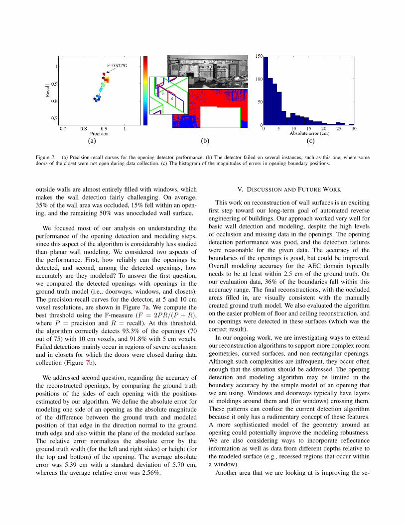
Figure 7. (a) Precision-recall curves for the opening detector performance. (b) The detector failed on several instances, such as this one, where somedoors of the closet were not open during data collection. (c) The histogram of the magnitudes of errors in opening boundary positions.
outside walls are almost entirely filled with windows, whichmakes the wall detection fairly challenging. On average,35% of the wall area was occluded, 15% fell within an open-ing, and the remaining 50% was unoccluded wall surface.
We focused most of our analysis on understanding theperformance of the opening detection and modeling steps,since this aspect of the algorithm is considerably less studiedthan planar wall modeling. We considered two aspects ofthe performance. First, how reliably can the openings bedetected, and second, among the detected openings, howaccurately are they modeled? To answer the first question,we compared the detected openings with openings in theground truth model (i.e., doorways, windows, and closets).The precision-recall curves for the detector, at 5 and 10 cmvoxel resolutions, are shown in Figure 7a. We compute thebest threshold using the F-measure (F = 2PR/(P + R),where P = precision and R = recall). At this threshold,the algorithm correctly detects 93.3% of the openings (70out of 75) with 10 cm voxels, and 91.8% with 5 cm voxels.Failed detections mainly occur in regions of severe occlusionand in closets for which the doors were closed during datacollection (Figure 7b).
We addressed second question, regarding the accuracy ofthe reconstructed openings, by comparing the ground truthpositions of the sides of each opening with the positionsestimated by our algorithm. We define the absolute error formodeling one side of an opening as the absolute magnitudeof the difference between the ground truth and modeledposition of that edge in the direction normal to the groundtruth edge and also within the plane of the modeled surface.The relative error normalizes the absolute error by theground truth width (for the left and right sides) or height (forthe top and bottom) of the opening. The average absoluteerror was 5.39 cm with a standard deviation of 5.70 cm,whereas the average relative error was 2.56%.
V. DISCUSSION AND FUTURE WORK
This work on reconstruction of wall surfaces is an excitingfirst step toward our long-term goal of automated reverseengineering of buildings. Our approach worked very well forbasic wall detection and modeling, despite the high levelsof occlusion and missing data in the openings. The openingdetection performance was good, and the detection failureswere reasonable for the given data. The accuracy of theboundaries of the openings is good, but could be improved.Overall modeling accuracy for the AEC domain typicallyneeds to be at least within 2.5 cm of the ground truth. Onour evaluation data, 36% of the boundaries fall within thisaccuracy range. The final reconstructions, with the occludedareas filled in, are visually consistent with the manuallycreated ground truth model. We also evaluated the algorithmon the easier problem of floor and ceiling reconstruction, andno openings were detected in these surfaces (which was thecorrect result).
In our ongoing work, we are investigating ways to extendour reconstruction algorithms to support more complex roomgeometries, curved surfaces, and non-rectangular openings.Although such complexities are infrequent, they occur oftenenough that the situation should be addressed. The openingdetection and modeling algorithm may be limited in theboundary accuracy by the simple model of an opening thatwe are using. Windows and doorways typically have layersof moldings around them and (for windows) crossing them.These patterns can confuse the current detection algorithmbecause it only has a rudimentary concept of these features.A more sophisticated model of the geometry around anopening could potentially improve the modeling robustness.We are also considering ways to incorporate reflectanceinformation as well as data from different depths relative tothe modeled surface (e.g., recessed regions that occur withina window).
Another area that we are looking at is improving the se-
mantics of the reconstructed model by explicitly classifyingthe openings (e.g., as windows, doors, or closets). Sucha classification scheme could also improve the detectionperformance, since class-specific detectors may be morereliable than the current, generic one.
Finally, we are investigating efficiency improvements, asthe current implementation is not optimized for speed. Weare looking into ways to improve the ray-tracing perfor-mance, for example by using graphics hardware to paral-lelize the task.
ACKNOWLEDGMENTS
This material is based upon work supported, in part, bythe National Science Foundation under Grant No. 0856558and by the Pennsylvania Infrastructure Technology Alliance.We thank Quantapoint, Inc., for providing experimental data.Any opinions, findings, and conclusions or recommendationsexpressed in this material are those of the authors and donot necessarily reflect the views of the National ScienceFoundation.
REFERENCES
[1] S. Becker. Generation and application of rules for qualitydependent facade reconstruction. Journal of Photogrammetryand Remote Sensing, 64(6):640–653, 2009. 2
[2] J. Bohm. Facade detail from incomplete range data. InProceedings of the ISPRS Congress, Beijing, China, 2008.1, 2
[3] J. Bohm, S. Becker, and N. Haala. Model refinement by inte-grated processing of laser scanning and photogrammetry. InProceedings of 3D Virtual Reconstruction and Visualization ofComplex Architectures (3D-Arch), Zurich, Switzerland, 2007.2
[4] A. Budroni and J. Bohm. Toward automatic reconstructionof interiors from laser data. In Proceedings of 3D-ARCH,February 2005. 2
[5] J. Davis, S. R. Marschner, M. Garr, and M. Levoy. Fill-ing holes in complex surfaces using volumetric diffusion.In Proceedings of the Symposium on 3D Data Processing,Visualization, and Transmission (3DPVT), 2002. 1, 2
[6] P. Debevec, C. J. Taylor, and J. Malik. Modeling and render-ing architecture from photographs: a hybrid geometry- andimage-based approach. In Proceedings of ACM SIGGRAPH,pages 11–20, 1996. 2
[7] F. Dell’Acqua and R. Fisher. Reconstruction of planar sur-faces behind occlusions in range images. Transactions on Pat-tern Analysis and Machine Intelligence (PAMI), 24(4):569–575, 2002. 2
[8] S. El-Hakim. Three-dimensional modeling of complex envi-ronments. In Videometrics and Optical Methods for 3D ShapeMeasurement (SPIE vol. 4309), 2001. 1
[9] S. F. El-Hakim, P. Boulanger, F. Blais, and J.-A. Beraldin. Asystem for indoor 3D mapping and virtual environments. InProceedings of Videometrics V (SPIE v. 3174), pages 21–35,1997. 2
[10] C. Frueh, S. Jain, and A. Zakhor. Data processing algorithmsfor generating textured 3D building facade meshes from laserscans and camera images. International Journal of ComputerVision (IJCV, 61(2):159–184, 2005. 1, 2
[11] Y. Furukawa, B. Curless, S. M. Seitz, and R. Szeliski. Re-constructing building interiors from images. In Proceedingsof the International Conference on Computer Vision (ICCV),pages 80–87, 2009. 2
[12] GSA. GSA BIM guide for 3D imaging, version 1.0, January2009. http://www.gsa.gov/bim. 1
[13] D. Hahnel, W. Burgard, and S. Thrun. Learning compact 3Dmodels of indoor and outdoor environments with a mobilerobot. Robotics and Autonomous Systems, 44(1):15–27, 2003.2
[14] H. Moravec. Robot spatial perception by stereoscopic visionand 3D evidence grids. Technical Report CMU-RI-TR-96-34,Carnegie Mellon University, September 1996. 3
[15] B. Okorn, X. Xiong, B. Akinci, and D. Huber. Towardautomated modeling of floor plans. In Proceedings of theSymposium on 3D Data Processing, Visualization and Trans-mission, Paris, France, 2010. 2
[16] M. Pauly, N. J. Mitra, J. Giesen, M. Gross, and L. J. Guibas.Example-based 3D scan completion. In Proceedings ofthe Third Eurographics Symposium on Geometry Processing,2005. 2
[17] M. Pollefeys, D. Nister, J. M. Frahm, A. Akbarzadeh, P. Mor-dohai, B. Clipp, C. Engels, D. Gallup, S. J. Kim, P. Merrell,C. Salmi, S. Sinha, B. Talton, L. Wang, Q. Yang, H. Stewe-nius, R. Yang, G. Welch, and H. Towles. Detailed real-timeurban 3D reconstruction from video. International Journal ofComputer Vision, 78(2-3):143–167, 2008. 2
[18] S. Pu and G. Vosselman. Knowledge based reconstruction ofbuilding models from terrestrial laser scanning data. ISPRSJournal of Photogrammetry and Remote Sensing, 64(6):575–584, 2009. 1, 2
[19] N. Ripperda and C. Brenner. Application of a formal grammarto facade reconstruction in semiautomatic and automaticenvironments. In Proceedings of AGILE Conference onGeographic Information Science, Hannover, Germany, 2009.2
[20] S. Roth and M. Black. Fields of experts: A framework forlearning image priors. In Proceedings of the Conferenceon Computer Vision and Pattern Recognition (CVPR), pages860–867, San Diego, California, 2005. 5
[21] S. Salamanca, P. Merchan, E. Perez, A. Adan, and C. Cerrada.Filling holes in 3D meshes using image restoration algo-rithms. In Proceedings of the Symposium on 3D Data Pro-cessing, Visualization, and Transmission (3DPVT), Atlanta,GA, 2008. 2, 5
[22] A. D. Sappa. Improving segmentation results by studyingsurface continuity. In Proceedings of the International Con-ference on Pattern Recognition (ICPR), volume 2, pages 929–932, 2002. 2
[23] I. Stamos, Y. Gene, G. Wolberg, and S. Zokai. 3D modelingusing planar segments and mesh elements. In Proceed-ings of 3D Data Processing, Visualization, and Transmission(3DPVT), pages 599–606, 2006. 2
[24] S. Thrun, C. Martin, Y. Liu, D. Hahnel, R. Emery-Montemerlo, D. Chakrabarti, and W. Burgard. A real-time expectation-maximization algorithm for acquiring multi-planar maps of indoor environments with mobile robots. IEEETransactions on Robotics, 20(3):433–443, 2004. 2
[25] V. Verma, R. Kumar, and S. Hsu. 3D building detection andmodeling from aerial lidar data. In Computer Vision andPattern Recognition, volume 2, pages 2213–2220, 2006. 1
[26] Q. Zheng, A. Sharf, G. Wan, Y. Li, N. J. Mitra, D. Cohen-Or, and B. Chen. Non-local scan consolidation for 3D urbanscenes. ACM Transactions on Graphics, 29(4), 2010. 2