Embed Size (px)
Citation preview

www.cranfield.ac.uk
3D positioning for industrial robotics
Tom Charrett, Thomas Kissinger & Ralph Tatam
MetMap - Integrated Metrology for Precision Manufacturing Conference, 22 - 23 January 2019, Sheffield, UK
Centre for Engineering Photonics,
Cranfield University, UK
2
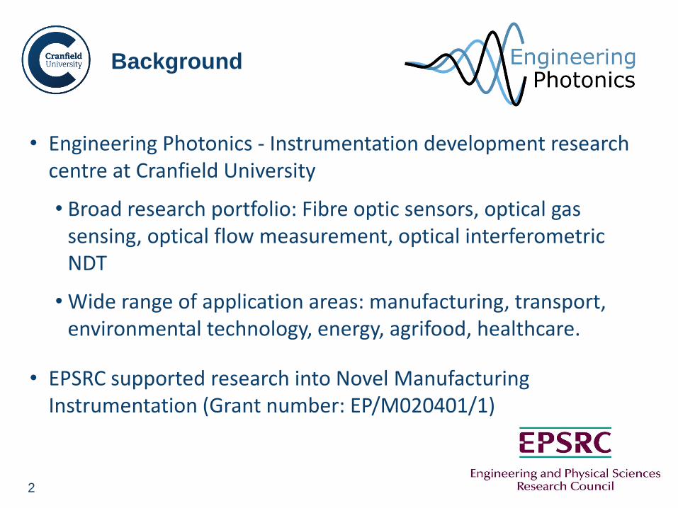
• Engineering Photonics - Instrumentation development research centre at Cranfield University
• Broad research portfolio: Fibre optic sensors, optical gas sensing, optical flow measurement, optical interferometric NDT
• Wide range of application areas: manufacturing, transport, environmental technology, energy, agrifood, healthcare.
• EPSRC supported research into Novel Manufacturing Instrumentation (Grant number: EP/M020401/1)
Background
3
• Aim: To develop new positioning instrumentation to improve flexibility and
precision in robotic manufacturing …
… overcome limitations in mechanical stiffness, process/environmental
disturbances and kinematics errors
… however also applicable in other areas
• Primarily focused on two complimentary optical measurements techniques
Range-resolved interferometry (RRI)
Laser speckle pattern correlation (LSC)
• Combination for multi-parameter relative positioning sensor:
Workpiece Positioning sensor (wPOS)
Background/Outline

www.cranfield.ac.uk
Range Resolved Interferometry (RRI)
5
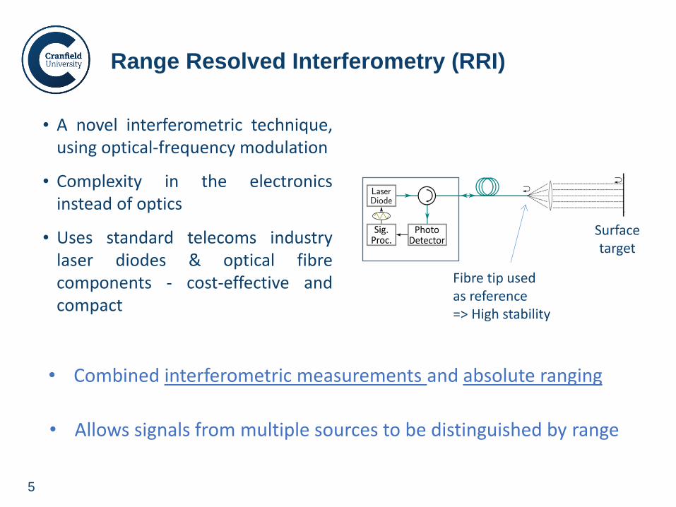
Range Resolved Interferometry (RRI)
• Combined interferometric measurements and absolute ranging
Surface target
Fibre tip used as reference => High stability
• A novel interferometric technique, using optical-frequency modulation
• Complexity in the electronics instead of optics
• Uses standard telecoms industry laser diodes & optical fibre components - cost-effective and compact
• Allows signals from multiple sources to be distinguished by range
6
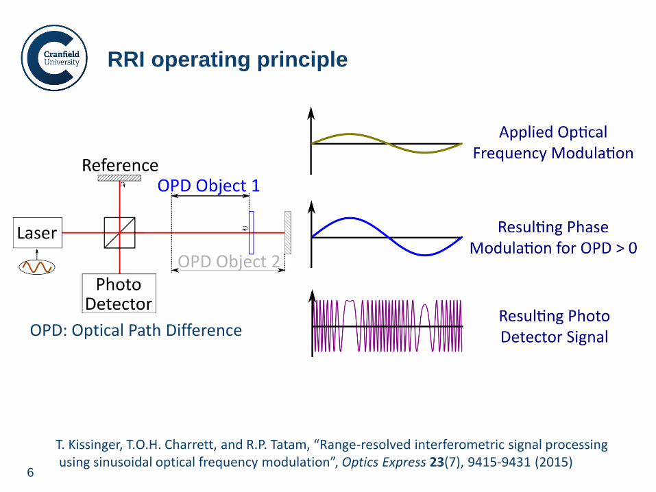
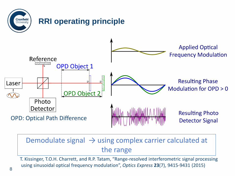
RRI operating principle
OPD: Optical Path Difference
T. Kissinger, T.O.H. Charrett, and R.P. Tatam, “Range-resolved interferometric signal processing using sinusoidal optical frequency modulation”, Optics Express 23(7), 9415-9431 (2015)
7
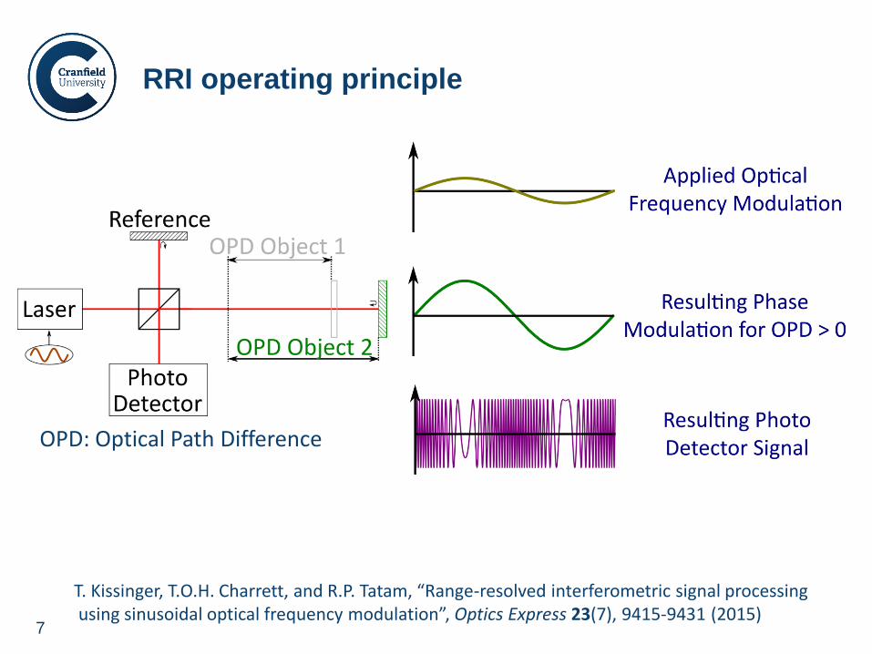
RRI operating principle
OPD: Optical Path Difference
T. Kissinger, T.O.H. Charrett, and R.P. Tatam, “Range-resolved interferometric signal processing using sinusoidal optical frequency modulation”, Optics Express 23(7), 9415-9431 (2015)
8
RRI operating principle
OPD: Optical Path Difference
T. Kissinger, T.O.H. Charrett, and R.P. Tatam, “Range-resolved interferometric signal processing using sinusoidal optical frequency modulation”, Optics Express 23(7), 9415-9431 (2015)
Demodulate signal → using complex carrier calculated at the range
9
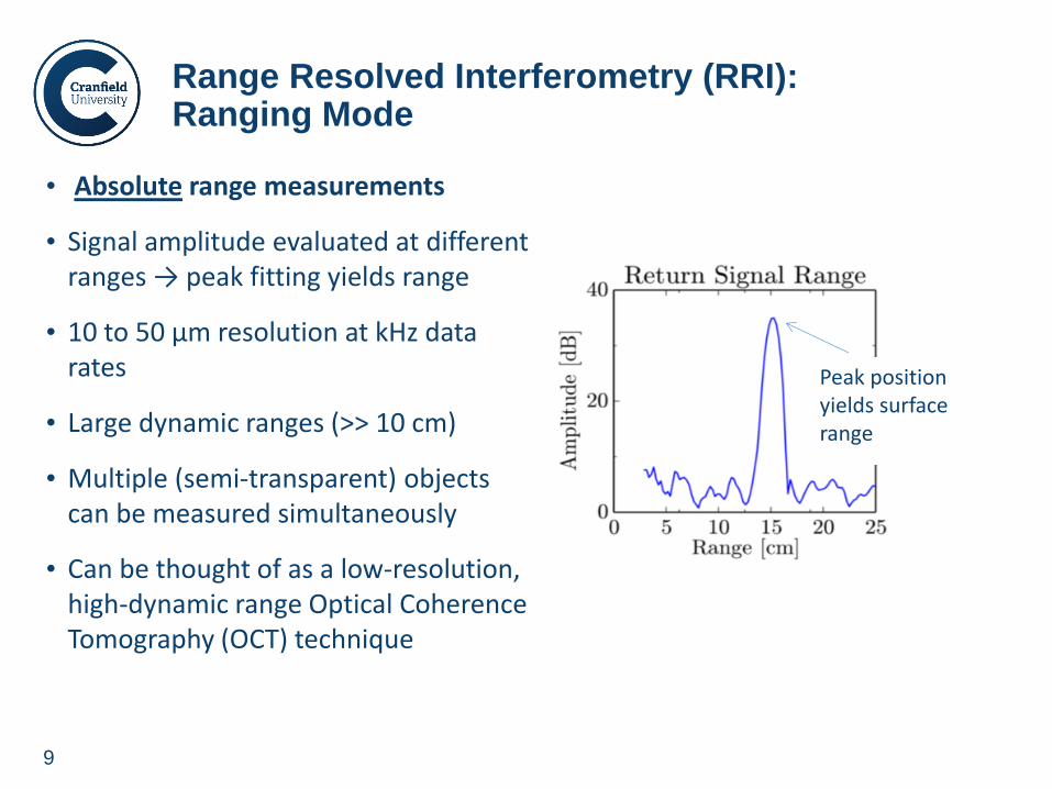
• Absolute range measurements
• Signal amplitude evaluated at different ranges → peak fitting yields range
• 10 to 50 µm resolution at kHz data rates
• Large dynamic ranges (>> 10 cm)
• Multiple (semi-transparent) objects can be measured simultaneously
• Can be thought of as a low-resolution, high-dynamic range Optical Coherence Tomography (OCT) technique
Range Resolved Interferometry (RRI): Ranging Mode
Peak position yields surface range
10
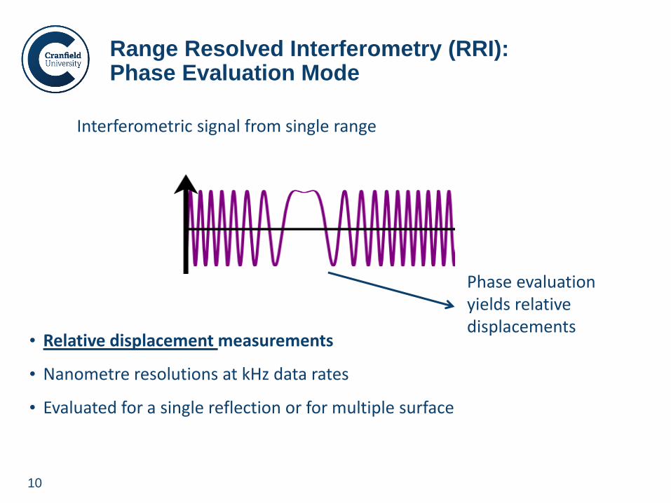
• Relative displacement measurements
• Nanometre resolutions at kHz data rates
• Evaluated for a single reflection or for multiple surface
Range Resolved Interferometry (RRI): Phase Evaluation Mode
Interferometric signal from single range
Phase evaluation yields relative displacements
11
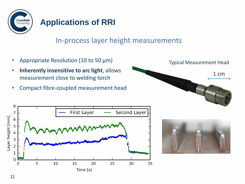
Applications of RRI
In-process layer height measurements
1 cm
Typical Measurement Head • Appropriate Resolution (10 to 50 µm)
• Inherently insensitive to arc light, allows measurement close to welding torch
• Compact fibre-coupled measurement head
12
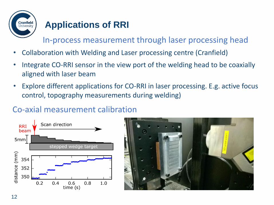
Applications of RRI
In-process measurement through laser processing head
• Collaboration with Welding and Laser processing centre (Cranfield)
• Integrate CO-RRI sensor in the view port of the welding head to be coaxially aligned with laser beam
• Explore different applications for CO-RRI in laser processing. E.g. active focus control, topography measurements during welding)
Co-axial measurement calibration
13
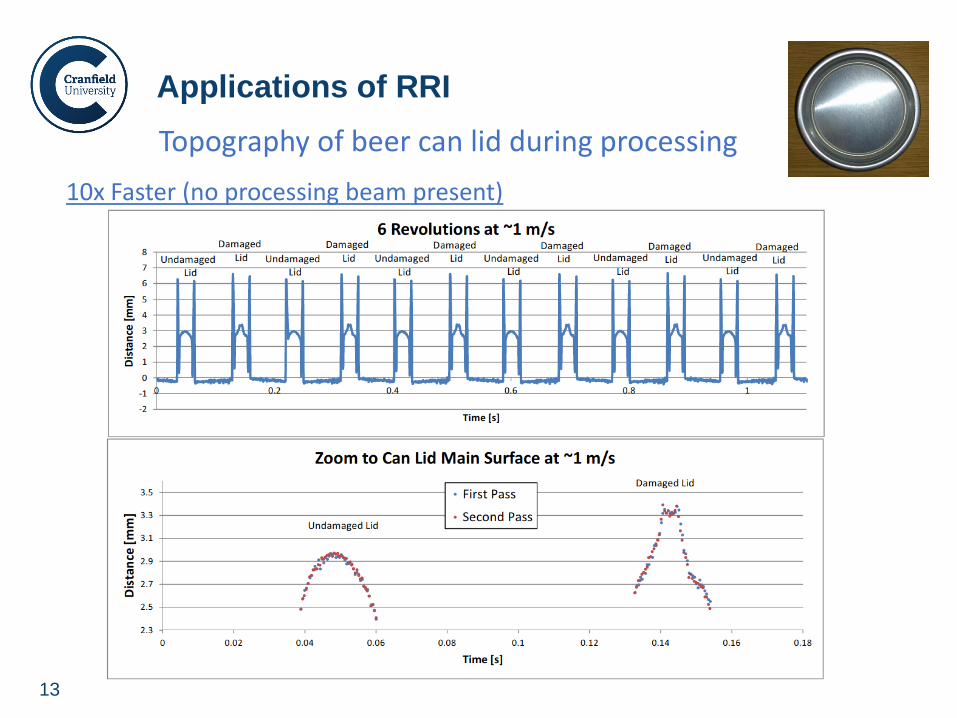
10x Faster (no processing beam present)
Applications of RRI
Topography of beer can lid during processing
14
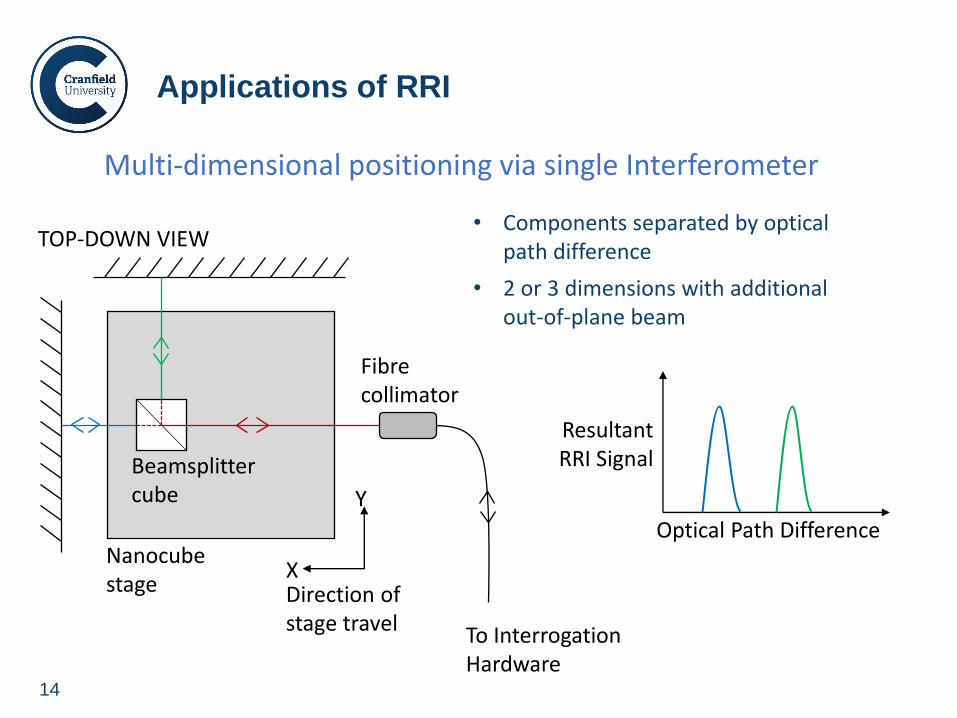
Applications of RRI
Multi-dimensional positioning via single Interferometer
Fibre collimator
To Interrogation Hardware
TOP-DOWN VIEW
Beamsplitter cube
X
Y
Nanocube stage Direction of
stage travel
Resultant RRI Signal
Optical Path Difference
• Components separated by optical path difference
• 2 or 3 dimensions with additional out-of-plane beam

www.cranfield.ac.uk
Laser Speckle Correlation (LSC)
16
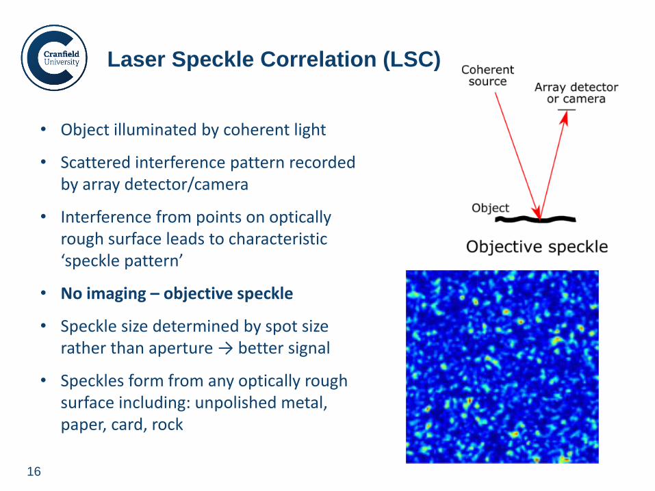
Laser Speckle Correlation (LSC)
• Object illuminated by coherent light
• Scattered interference pattern recorded by array detector/camera
• Interference from points on optically rough surface leads to characteristic ‘speckle pattern’
• No imaging – objective speckle
• Speckle size determined by spot size rather than aperture → better signal
• Speckles form from any optically rough surface including: unpolished metal, paper, card, rock
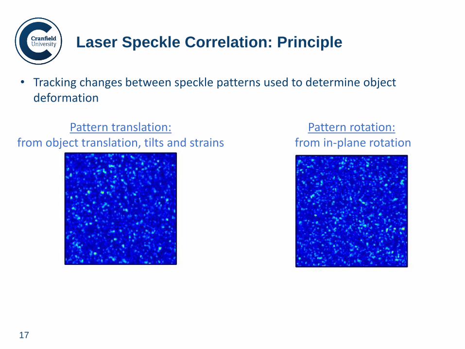
17
• Tracking changes between speckle patterns used to determine object deformation
Laser Speckle Correlation: Principle
Pattern translation: from object translation, tilts and strains
Pattern rotation: from in-plane rotation
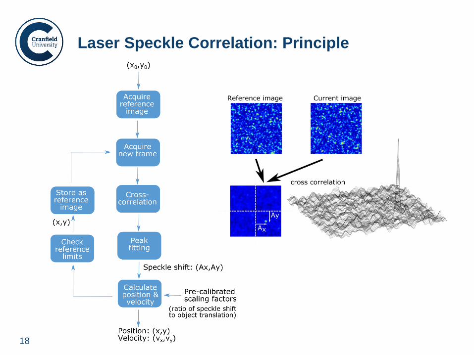
18
Laser Speckle Correlation: Principle
19
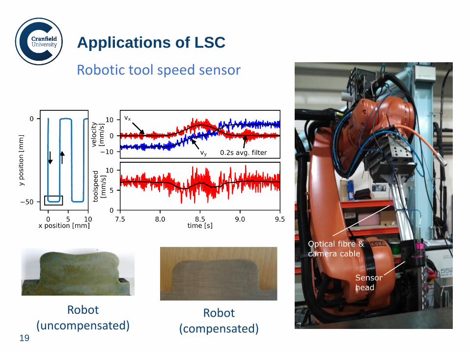
Applications of LSC
Robot (compensated)
Robot (uncompensated)
Robotic tool speed sensor
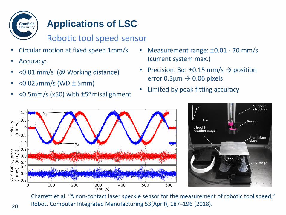
20
• Circular motion at fixed speed 1mm/s
• Accuracy:
• <0.01 mm/s (@ Working distance)
• <0.025mm/s (WD ± 5mm)
• <0.5mm/s (x50) with ±5o misalignment
Applications of LSC
Charrett et al. “A non-contact laser speckle sensor for the measurement of robotic tool speed,” Robot. Computer Integrated Manufacturing 53(April), 187–196 (2018).
• Measurement range: ±0.01 - 70 mm/s (current system max.)
• Precision: 3σ: ±0.15 mm/s → position error 0.3µm → 0.06 pixels
• Limited by peak fitting accuracy
Robotic tool speed sensor
21
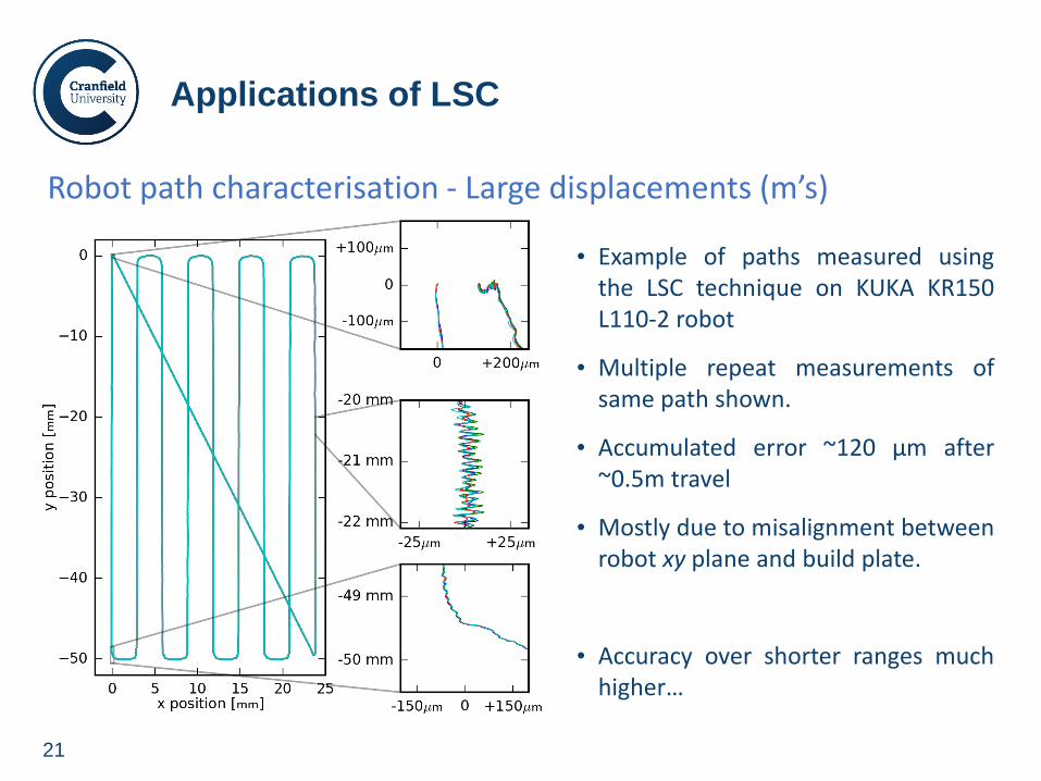
Applications of LSC
Robot path characterisation - Large displacements (m’s)
• Example of paths measured using the LSC technique on KUKA KR150 L110-2 robot
• Multiple repeat measurements of same path shown.
• Accumulated error ~120 µm after ~0.5m travel
• Mostly due to misalignment between robot xy plane and build plate.
• Accuracy over shorter ranges much higher…
22
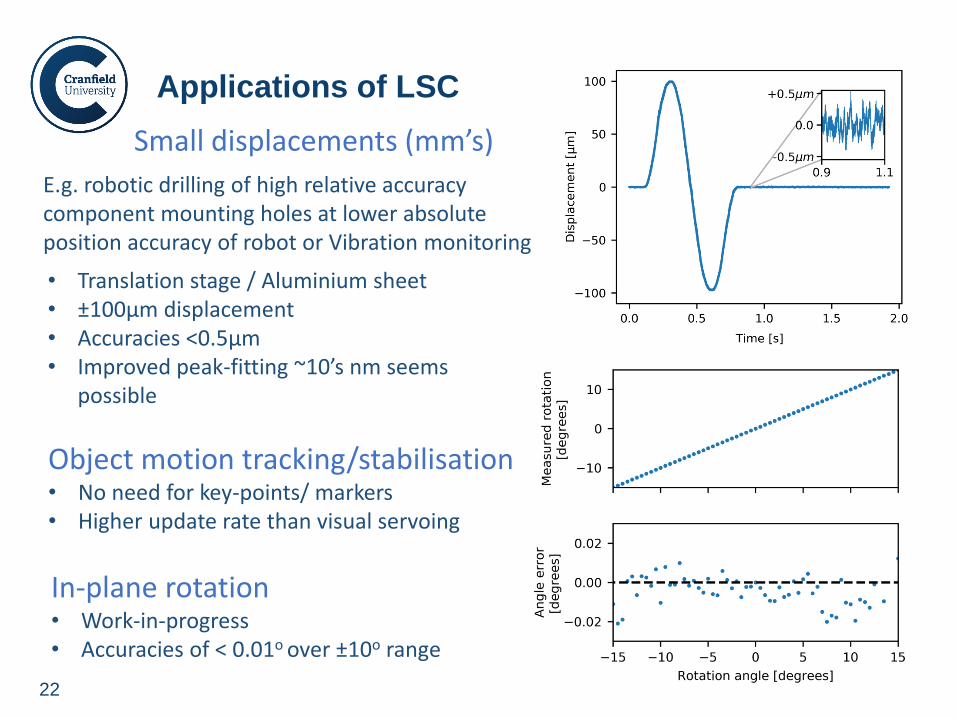
Applications of LSC
Small displacements (mm’s)
E.g. robotic drilling of high relative accuracy component mounting holes at lower absolute position accuracy of robot or Vibration monitoring
• Translation stage / Aluminium sheet • ±100µm displacement • Accuracies <0.5µm • Improved peak-fitting ~10’s nm seems
possible
Object motion tracking/stabilisation • No need for key-points/ markers • Higher update rate than visual servoing
In-plane rotation • Work-in-progress • Accuracies of < 0.01o over ±10o range

www.cranfield.ac.uk
Workpiece Positioning Sensor (wPOS)
24
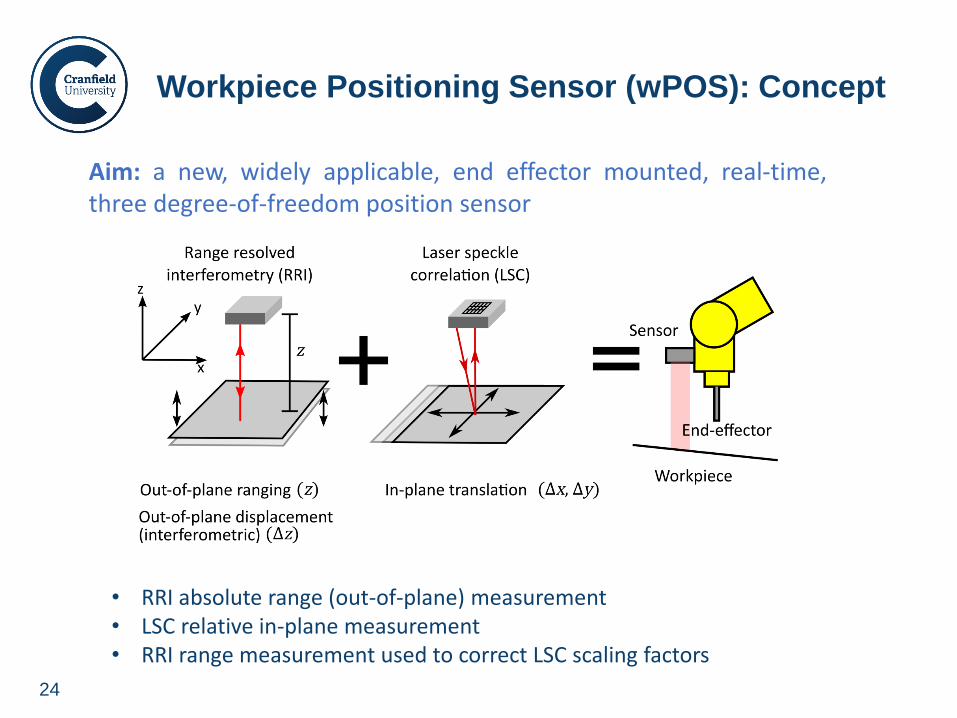
Workpiece Positioning Sensor (wPOS): Concept
Aim: a new, widely applicable, end effector mounted, real-time, three degree-of-freedom position sensor
• RRI absolute range (out-of-plane) measurement • LSC relative in-plane measurement • RRI range measurement used to correct LSC scaling factors
25
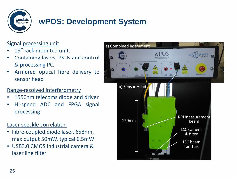
wPOS: Development System
Signal processing unit • 19” rack mounted unit. • Containing lasers, PSUs and control
& processing PC. • Armored optical fibre delivery to
sensor head
Range-resolved interferometry • 1550nm telecoms diode and driver • Hi-speed ADC and FPGA signal
processing
Laser speckle correlation • Fibre-coupled diode laser, 658nm,
max output 50mW, typical 0.5mW • USB3.0 CMOS industrial camera &
laser line filter
26
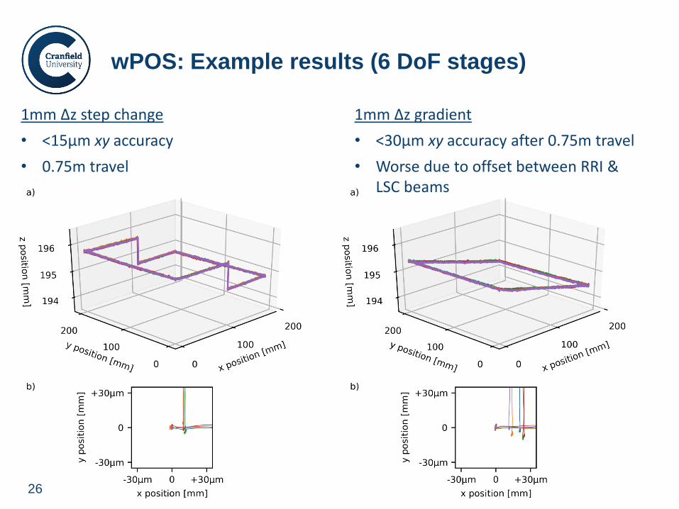
wPOS: Example results (6 DoF stages)
1mm Δz step change
• <15µm xy accuracy
• 0.75m travel
1mm Δz gradient
• <30µm xy accuracy after 0.75m travel
• Worse due to offset between RRI & LSC beams
27
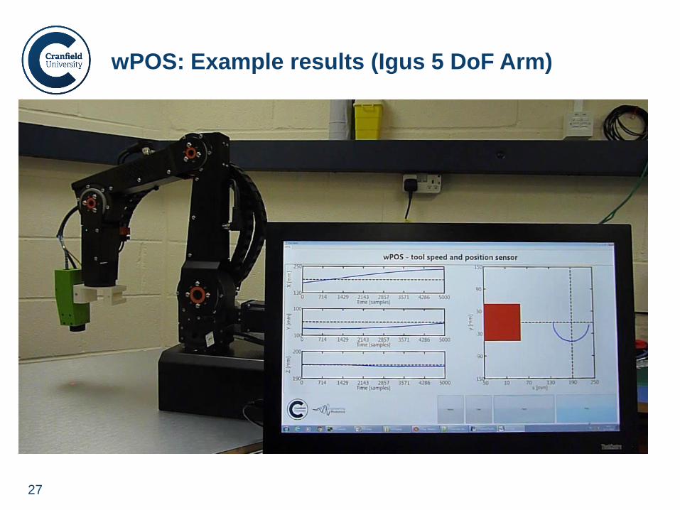
wPOS: Example results (Igus 5 DoF Arm)
28
• Two optical techniques for position/displacement measurements
• Combined three-degree of freedom sensor
• Application examples and potential areas of application
Future directions • Further instrumentation development and improvements
• Fully characterize positioning performance of wPOS system
• Addition of further degrees-of-freedom
• Application based trials …
Conclusions
Acknowledgements
Engineering and Physical Sciences Research Council (EPSRC) UK
[grant numbers EP/M020401/1, EP/N002520/1]
Welding Engineering and Laser Processing Centre, Cranfield University for collaborations involving the WAAM process.