Embed Size (px)
Citation preview
Abstract — Computer Aided Engineering (CAE) techniques
provide effective solutions for automating the whole product
development chain process. Designers, engineers, manufacturing
professionals and researchers can now leverage solid modeling data
and multi-physics analysis in ways that were inconceivable just few
years ago. Among CAE techniques, Computer Aided Design (CAD)
has been the most effective in providing methodologies capable of
compressing product design and manufacturing cycles, assuring
faster turnaround time between design and simulation and improving
product quality. Designers and manufacture companies reap the
rewards of 3D CAD modelling; as a consequence, research is
unceasingly stimulated to look forward. On one hand, research aims
to improve capabilities of existing CAD methods and tools; on the
other hand novel approaches are extensively investigated with the
ambition of carrying out innovative CAD techniques capable of
lighting sparking design innovation and creativity. This is
particularly true for mechanical design: fast and robust 3D retrieval
from 2D drawings that was considered future trend few years ago, is
now a key target for commercial software houses like Dassault
Systems® and Autodesk® as well as a vigorous focus from an
academic outlook. Unfortunately, even if a number of works have
been carried out during the last decades, these are mainly described
by a conceptual point of view. To derive an orderly procedure
covering the necessary steps for retrieving 3D models from
mechanical drawings could provide a dramatic boost to researchers
and practitioners that introduce this issue on their research.
Therefore, the main aim of the present work is to carry out a
systematic clear and concise step-by-step procedure for 3D retrieval
starting from wireframe models. Since the intent is to afford an as
clear as possible, guided, procedure for 3D reconstruction,
mathematical description is limited to the simplest case of polyhedral
objects. The proposed procedures, inspired by state of the art works,
can be effectively contribute to speed-up the possible implementation
of methodologies confronting the 3D reconstruction problem.
Keywords — Pseudo-wireframe, 3D Retrieval, Mechanical
Drawings, Computer Aided Design, Computational Geometry.
I. INTRODUCTION
ODAY , Computer-aided engineering (CAE) techniques
afford effective solutions for automating the whole
product development chain process. Designers, engineers,
manufacturing professionals and researchers can now leverage
solid modeling data and multi-physics analysis in ways that
were inconceivable just few years ago [1]. Among CAE
techniques, such as computer-aided analysis (CAA),
computer-integrated manufacturing (CIM), computer-aided
manufacturing (CAM), material requirements planning
(MRP), and computer-aided planning (CAP), Computer Aided
Design (CAD) is a central issue in the mechanical design field
since it provides designers with a series of tools for
streamlining design processes such as drafting, visualization,
simulation, documentation, and manufacturing processes.
Designers and manufacture companies reap the rewards of 3D
CAD modelling; as a consequence, research is unceasingly
stimulated to look forward. On one hand, research aims to
improve capabilities of existing CAD methods and tools; on
the other hand novel approaches are extensively investigated
with the ambition of carrying out innovative CAD techniques
capable of lighting sparking design innovation and creativity.
This is particularly true for mechanical design: fast and robust
3D retrieval from 2D drawings that was considered future
trend few years ago, is now a key target for commercial
software houses like Dassault Systems® and Autodesk® as
well as a vigorous focus from an academic outlook.
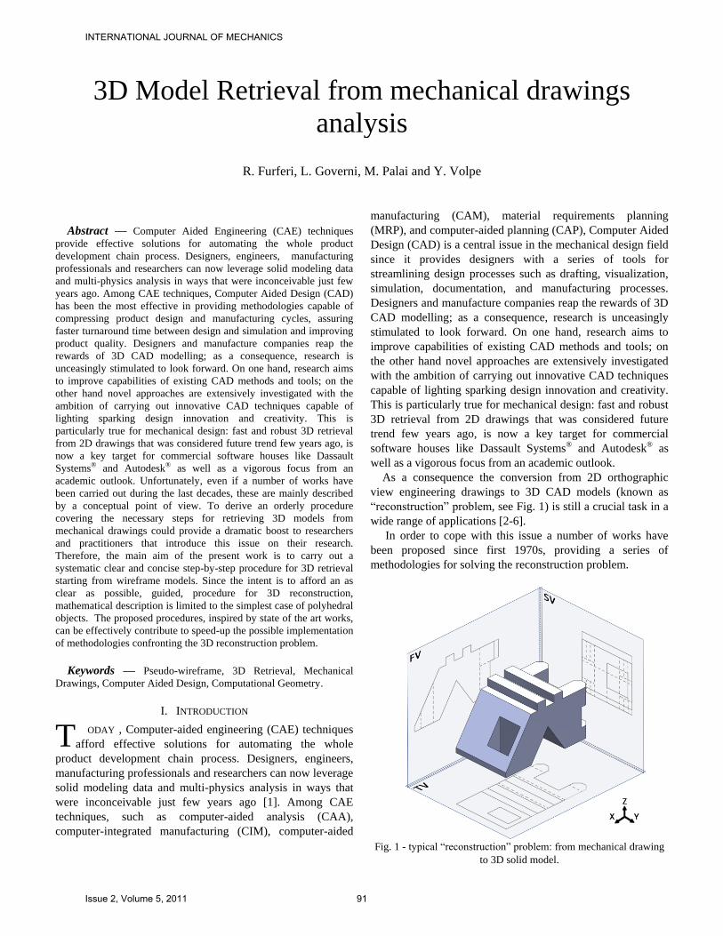
As a consequence the conversion from 2D orthographic
view engineering drawings to 3D CAD models (known as
“reconstruction” problem, see Fig. 1) is still a crucial task in a
wide range of applications [2-6].
In order to cope with this issue a number of works have
been proposed since first 1970s, providing a series of
methodologies for solving the reconstruction problem.
Fig. 1 - typical “reconstruction” problem: from mechanical drawing
to 3D solid model.
3D Model Retrieval from mechanical drawings
analysis
R. Furferi, L. Governi, M. Palai and Y. Volpe
T
INTERNATIONAL JOURNAL OF MECHANICS
Issue 2, Volume 5, 2011 91
Generally speaking, the works proposed at the state of the
art can be divided in two different families:
1. wireframe-oriented approaches, that are also known as B-
rep (Boundary representation) methods;
2. volume-oriented approaches, also called CSG
(Constructive Solid Geometry) methods.
A useful review of relevant published works, regarding
both B-rep and CSG approaches, is provided by two recent
publications [2,7]. Recently the preferred approach for
performing 3D reconstruction has been the B-rep based one
[8-15]. This is mainly due to the fact that the CSG approach is
less suitable to support complex shapes and usually requires
heavier user interaction compared to the B-rep one. For such
reasons, the present work confronts with the B-rep based
reconstruction methodologies.
It is commonly accepted that B-rep reconstruction can be
split into two main phases: the first is the reconstruction of the
pseudo-wireframe model (set of all possible wireframe models
that can be originated by an assigned set of orthographic
views); the second is the reconstruction of the 3D solid (or
surface) model(s) from the obtained pseudo-wireframe model
and coherent with the assigned orthographic views [16, 17] .
Unfortunately, even if a number of works have been carried
out during the last decades, these are mainly described by a
conceptual point of view. To derive an orderly procedure
covering the necessary steps for retrieving 3D models from
mechanical drawings could provide a dramatic boost to
researchers and practitioners that introduce this issue on their
research. Therefore, the main aim of the present work is to
carry out a systematic clear and concise step-by-step
procedure for 3D retrieval starting from wireframe models.
Since the intent is to afford an as clear as possible, guided,
procedure for 3D reconstruction, mathematical description is
limited to the simplest case of polyhedral objects. The
proposed procedures, inspired by state of the art works, can be
effectively contribute to speed-up the possible implementation
of methodologies confronting the 3D reconstruction problem.
A comprehensive, orderly, unambiguous and automatic
procedure meant to help researchers and practitioners who
want to deal with the first phase of the reconstruction problem
has been provided by the authors in a previous work [18].
Starting from the wireframe model obtained with this
methodology, the aim of the present work is to retrieval a 3D
model starting from wireframe one obtained from mechanical
drawings.
The reconstruction procedure involves a number of
software routines; by means of them, an initial 3D vectorial
wireframe model is processed and a set of 3D solutions,
consistent with the initial wireframe model, is extracted. The
obtained 3D models are subsequently output according to the
most common 3D exchange formats (e.g. IGES, STEP,
Parasolid, etc.). The proposed procedure has been
implemented using MatLab® programming language to assess
its functionality. Extensive testing, carried out on a number of
case studies, has demonstrated the effectiveness of the
presented approach. Based on the results obtained in the
testing phase, it is possible to state the suitability of the
proposed procedure to automate the reconstruction of
polyhedric objects by a set of orthographic projections. The
procedure can be effectively used as a common basis to speed-
up the possible implementation of methodologies confronting
the reconstruction problem.
After a brief description of the first main phase (wireframe
model reconstruction), provided in section 2, the paper
focuses on 3D model reconstruction tasks and validation
(section 3). In order to help readers in seeing the proposed
approach through, a case study is carried on along the entire
reconstruction procedure.
II. WIREFRAME RECONSTRUCTION
As already stated, the main aim of the present work is to
reconstruct a 3D model when a wireframe one is obtained
starting from a set of orthographic projections. Wireframe
model can be obtained according to the following tasks [18]:
1) 2D orthographic data extraction.
2) 2D vertexes and edges labeling.
3) 2D edges and vertexes manipulation.
4) 3D wireframe reconstruction.
A. 2D orthographic data extraction
The first step of the wireframe reconstruction procedure
consists of extracting, for instance from a DXF file, the end-
point coordinates of each geometric feature (e.g. lines) and
storing them into a database. The result is an ordered matrix
(size 2n × 3) of n edges, each one defined by two triplets of
coordinates representing the endpoint vertexes. Moreover,
each 2D geometric feature is automatically assigned to its
orthographic projection thus obtaining three different sets of
entities (edges).
B. 2D vertexes and edges labeling
Once known the set of orthographic projections a
conversion of the geometric data into topological ones is
performed in order to reduce the information to be processed.
Therefore, a topological data structure is accomplished. In
detail, each vertex of each projection is labeled with a
progressive number.
Each 2D edge can be now represented by the label of its
endpoints rather than the actual endpoints coordinates.
Thus, only 3 parameters (a progressive number identifying
2D edge and the label of its two endpoints) are now used to
properly identify each edge instead of 7 parameters (a
progressive number identifying 2D edge and the coordinates
of its two endpoints).
C. 2D vertexes and edges manipulation
When orthographic projections come out from a digital
CAD format, e.g. DXF, even if an object is represented by a
univocal set of projections, these can be drawn by using
different combination of geometric entities. The segment
INTERNATIONAL JOURNAL OF MECHANICS
Issue 2, Volume 5, 2011 92
highlighted in fig. 1a can be made up of a number of straight
vectors (from 1 to 8 as shown in fig. 1c).
Such combination of vectors, anyway, is uncorrelated with
the one which would be generated by the projection of the
object's 3D edges lying on the plane orthogonal to the view
and whose trace contains the original segment (fig. 1c). In
other words, the same projection can be represented by
different digital CAD files.
As a consequence, in order to obtain a univocally defined
vectorial representation, comprising all the possible
configurations, a procedure, called “segmentation” is
recommended.
First, for each edge, an iterative procedure checks for the
possible existence of intermediate vertices. If no intermediate
vertex is found, the procedure stops. Otherwise the found
intermediate vertex causes the creation of two new edges
(unless one of them already exists). This task is performed for
each set of edges belonging to a projection, thus adding new
edges to the original set.
After the ''segmentation'' task, a check of collinearity of
edges is performed. This phase is fundamental when two non-
contiguous vertices are linked by two or more edges (all
collinear one with each other). If this check is inaccurate it
could happen that two visually identical projections are
described by two different digital representations. When a
collinearity of edges is detected, a new set of edges is added to
the original one. The collinearity can be detected as the logical
product of concatenation (two edges sharing the same vertex)
and parallelism.
D. 3D wireframe reconstruction
Once a database of edges and vertices for each projection
view is built, it is possible to reconstruct a pseudo vertex
skeleton represented by a matrix :
321
31
21
111111
qqqqqqq vvvzyx
vvvzyx
w
w
(1)
Each row vector i of describes a 3D vertex where q is
the total number of 3D vertexes. The first element ( ) of each
row represents the label of the 3D vertex; the following three
elements ( zyx ,, ) are the coordinates of the 3D vertexes while
the remaining elements ( 321 ,, vvv ) are the labels of the 3D
vertexes projection on, respectively, the three coordinate
planes TV, FV and SV1. The definition of the pseudo-
skeleton matrix allows to build the pseudo-wireframe. In other
words, once 3D vertexes have been identified it is possible to
reconstruct the set of 3D edges coherent with the starting
orthogonal views.
First the set of 3D edges that are not orthogonal to any
projection is assessed; then a similar procedure is carried out
for the 3D edges that are orthogonal respectively to TV, FV
1 Top View, Front View and Side View.
and SV.
The result is a matrix containing the entire set of 3D
edges:
bs
ass
ba
r
r
111
(2)
Each row vector ie identifies a 3D edge where s is the total
number of 3D edges. First element of each row is the label of
the 3D edge; the other two elements represents the labels of
the two 3D edge endpoints.
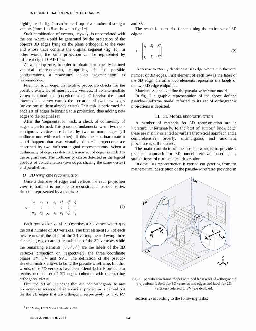
Matrixes and define the pseudo-wireframe model.
In fig. 2 a graphic representation of the above defined
pseudo-wireframe model referred to its set of orthographic
projections is depicted.
III. 3D MODEL RECONSTRUCTION
A number of methods for 3D reconstruction are in
literature; unfortunately, to the best of authors’ knowledge,
these are mainly oriented towards a theoretical approach and a
comprehensive, orderly, unambiguous and automatic
procedure is still required.
The main contribute of the present work is to provide a
practical approach for 3D model retrieval based on a
straightforward mathematical description.
In detail 3D reconstruction is carried out (starting from the
mathematical description of the pseudo-wireframe provided in
Fig. 2 – pseudo-wireframe model obtained from a set of orthographic
projections. Labels for 3D vertexes and edges and label for 2D
vertexes (referred to FV) are depicted.
section 2) according to the following tasks:
INTERNATIONAL JOURNAL OF MECHANICS
Issue 2, Volume 5, 2011 93
- Detection of planar edge cycles.
- Detection of face cycles.
- Creation of virtual block cycles.
- Solution(s) validation.
A. Detection of planar edge cycles
The first step for reconstruction consists of the
identification of all the possible 3D faces defining the
boundary of the final solution. In order to achieve such a goal,
the following three phases have been devised:
Detection of the planes defined by all the couples of
pseudo-wireframe edges sharing an endpoint.
Identification of all the edge cycles lying on each
plane.
Definition of the faces by means of the analysis of
each edge cycle.
Planes detection
Each 3D edge must lie on at least two planes and each plane
must include at least three edges. So, in order to detect planes,
these two conditions have to be respected. The first step is to
list all the possible planes obtainable by means of normalized
cross products between couples of edges sharing an endpoint
(which results in the vector normal to the plane defined by the
two edges).
Let ut and vt be two generic 3D edges:
4),3,(3),3,(2),3,(
4),2,(3),2,(2),2,(
4),3,(3),3,(2),3,(
4),2,(3),2,(2),2,(
vEvEvE
vEvEvEt
uEuEuE
uEuEuEt
v
u
(3)
The normalized cross product between ut and vt defines a
series of generic plane versor and a series of plane labels
n , under the following conditions:
],,,,[
;
;
);...(
...)()()(:,
nkjip
nif
nif
tt
ttkji
vuEtEtvu
bu
bv
bu
av
bu
au
bv
au
av
au
vu
vu
bv
bu
av
bu
bv
au
av
au
vu
(4)
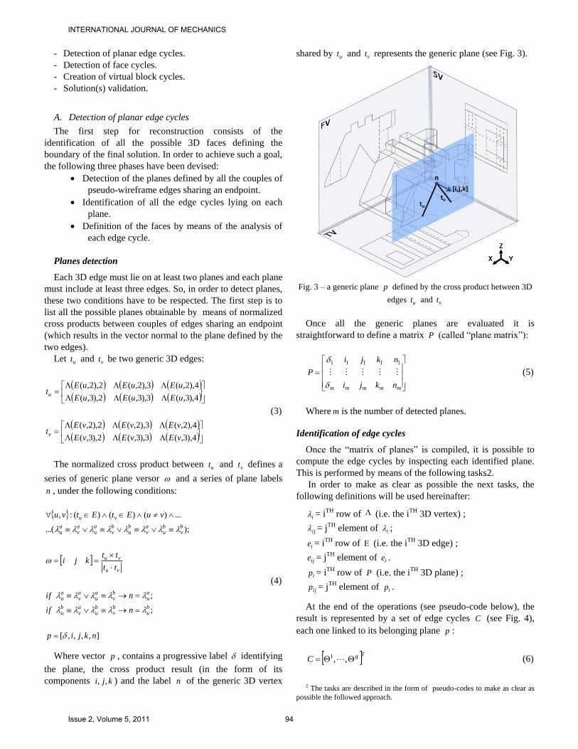
Where vector p , contains a progressive label identifying
the plane, the cross product result (in the form of its
components kji ,, ) and the label n of the generic 3D vertex
shared by ut and vt represents the generic plane (see Fig. 3).
Fig. 3 – a generic plane p defined by the cross product between 3D
edges ut and vt
Once all the generic planes are evaluated it is
straightforward to define a matrix P (called “plane matrix”):
mmmmm nkji
nkji
P 11111
(5)
Where m is the number of detected planes.
Identification of edge cycles
Once the “matrix of planes” is compiled, it is possible to
compute the edge cycles by inspecting each identified plane.
This is performed by means of the following tasks2.
In order to make as clear as possible the next tasks, the
following definitions will be used hereinafter:
i = iTH row of (i.e. the iTH 3D vertex) ;
ij = jTH element of i ;
ie = iTH row of (i.e. the iTH 3D edge) ;
ije = jTH element of ie .
ip = iTH row of P (i.e. the iTH 3D plane) ;
ijp = jTH element of ip .
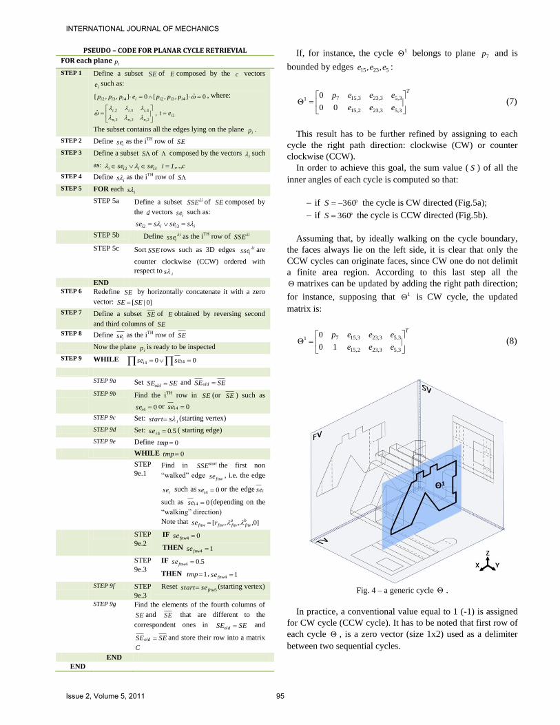
At the end of the operations (see pseudo-code below), the
result is represented by a set of edge cycles C (see Fig. 4),
each one linked to its belonging plane p :
TgC ,,1 (6)
2 The tasks are described in the form of pseudo-codes to make as clear as
possible the followed approach.
INTERNATIONAL JOURNAL OF MECHANICS
Issue 2, Volume 5, 2011 94
PSEUDO – CODE FOR PLANAR CYCLE RETRIEVIAL
FOR each planeip
STEP 1 Define a subset SE of E composed by the c vectors
ie such as:
0ˆ],,[0],,[ 432432 iiiiiii pppeppp , where:
22,2,2,
4,3,2, , ˆ
innn
iiiei
The subset contains all the edges lying on the plane ip .
STEP 2 Define ise as the iTH row of SE
STEP 3 Define a subset S of composed by the vectors i such
as: 1,...,cisese iiii 32
STEP 4 Define is as the iTH row of S
STEP 5 FOR each is
STEP 5a Define a subset iSSE of SE composed by
the d vectors ise such as:
iiii ssesse 32
STEP 5b Define iisse as the iTH row of iSSE
STEP 5c Sort SSE rows such as 3D edges iisse are
counter clockwise (CCW) ordered with
respect tois
END
STEP 6 Redefine SE by horizontally concatenate it with a zero
vector: ]0|[SESE
STEP 7 Define a subset SE of E obtained by reversing second
and third columns of SE
STEP 8 Define ise as the iTH row of SE
Now the plane ip is ready to be inspected
STEP 9 WHILE 00 44 ii sese
STEP 9a Set SESEold and SESEold
STEP 9b Find the iTH row in SE (or SE ) such as
04 ise or 04 ise
STEP 9c Set: isstart (starting vertex)
STEP 9d Set: 5.04 ise ( starting edge)
STEP 9e Define 0tmp
WHILE 0tmp
STEP
9e.1 Find in startSSE the first non
“walked” edge fnwse , i.e. the edge
ise such as 04 ise or the edge ise
such as 04 ise (depending on the
“walking” direction)
Note that ]0,,,[ bfnv
afnvfnvfnw rse
STEP
9e.2
IF 04 fnwse
THEN 14 fnwse
STEP
9e.3
IF 5.04 fnwse
THEN 1tmp , 14 fnwse
STEP 9f STEP
9e.3
Reset 3fnwsestart (starting vertex)
STEP 9g Find the elements of the fourth columns of
SE and SE that are different to the
correspondent ones in SESEold and
SESEold and store their row into a matrix
C
END
END
If, for instance, the cycle 1 belongs to plane 7p and is
bounded by edges 52315 ,, eee :
T
eee
eeep
3,53,232,15
3,53,233,1571
00
0 (7)
This result has to be further refined by assigning to each
cycle the right path direction: clockwise (CW) or counter
clockwise (CCW).
In order to achieve this goal, the sum value ( S ) of all the
inner angles of each cycle is computed so that:
if 360S the cycle is CW directed (Fig.5a);
if 360S the cycle is CCW directed (Fig.5b).
Assuming that, by ideally walking on the cycle boundary,
the faces always lie on the left side, it is clear that only the
CCW cycles can originate faces, since CW one do not delimit
a finite area region. According to this last step all the
matrixes can be updated by adding the right path direction;
for instance, supposing that 1 is CW cycle, the updated
matrix is:
T
eee
eeep
3,53,232,15
3,53,233,1571
10
0 (8)
Fig. 4 – a generic cycle .
In practice, a conventional value equal to 1 (-1) is assigned
for CW cycle (CCW cycle). It has to be noted that first row of
each cycle , is a zero vector (size 1x2) used as a delimiter
between two sequential cycles.
INTERNATIONAL JOURNAL OF MECHANICS
Issue 2, Volume 5, 2011 95
a) CW cycle b) CCW cycle
Fig. 5 – CW and CCW cycles.
Once cycles are defined, each face f , commonly known as
“virtual face”, is described by a row vector storing the label of
the linked plane and the list of all the edges representing the
face boundary. Continuing the example described above and
supposing that 1 is CCW:
1,51,231,157 ,,, eeepf (9)
All the detected faces defines a matrix F of size
)1( max nn f where: fn is the number of faces, while maxn is
the number of edges surrounding the face delimited by the
maximum number of edges3. Accordingly, the matrix F is
obtained by appending all the vectors f :
1
1
max
nnn
ff
f
f
F (10)
B. Detection of faces cycles
It is known that the set of faces resulting from the previous
task generally represents a superset of the face set describing
the actual 3D solid [16, 17]. In order to complete the
reconstruction process, it is, thereby, necessary to identify the
set of elementary 3D blocks (commonly known as “virtual
blocks”) whose combinations provide the final 3D geometries.
The block detection task is performed by detecting faces
cycles. This is carried out analogously to the face detection
task previously described; the main difference between the
two is represented by the space dimensionality: blocks are
managed in 3D space while faces in 2D one. For
completeness, a concise pseudo-code for faces cycles
detection is described below.
From the algorithm point of view, this task requires a
“warm up” phase for the compilation of two auxiliary
matrixes:
- 1F (size s × max{# ife })
3 The number of elements in a generic f depends on the number of
surrounding edges and this last is not fixed a priori. As a consequence, in
order to append all the face vectors into the faces matrix F all the vectors
f are required to have the same length. This is obtained by adding a series of
0 elements until the proper length is reached.
- 2F (size fn × max{# ief } ).
Each row of matrix 1F is devoted to an edge e and
contains the labels of all the faces ife having e among their
boundary edges.
The second matrix allows a fast detection of the edges
ief composing the boundary of each face; each row is devoted
to a face f and contains the labels of all the edges ief
bounding it. Once these two auxiliary matrixes have been
compiled, the procedure carries on detecting the loops of faces
(blocks). The face cycle identification is a close analog of the
one devised for the planar edge cycles, described in the
previous section. The procedure stops when the two sides of
each face has been used in cycle detection process. The
implemented procedure related to the cycles of faces is
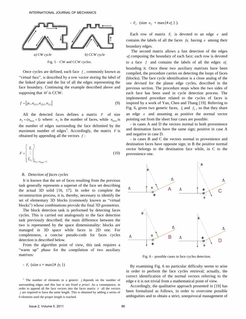
inspired by a work of Yan, Chen and Thang [19]. Referring to
Fig. 6, given two generic faces, 1f and 2f , so that they share
an edge e and assuming as positive the normal vector
pointing out from the sheet four cases are possible:
- in cases A and D the vectors normal to both provenience
and destination faces have the same sign; positive in case A
and negative in case D.
- in cases B and C the vectors normal to provenience and
destination faces have opposite sign; in B the positive normal
vector belongs to the destination face while, in C to the
provenience one.
Fig. 6 – possible cases in face cycles detection.
By examining Fig. 6 no particular difficulty seems to arise
in order to perform the face cycles retrieval; actually, the
correct identification of the normal vectors referring to the
edge e it is not trivial from a mathematical point of view.
Accordingly, the qualitative approach presented in [19] has
been formalized as follows, in order to overcome possible
ambiguities and to obtain a strict, unequivocal management of
INTERNATIONAL JOURNAL OF MECHANICS
Issue 2, Volume 5, 2011 96
the loop detection. By means of a series of cross product
comparisons involving the two face normals and the edge e ,
the authors provide a method that allows to correctly identify
the right configuration among the four ones depicted in Fig. 6.
The final result of this task is a matrix B of blocks
b defined as follows:
bnb
b
B 1
(11)
Where each block is represented by a vector b given by the
label of the block ( ) and the label list of the faces composing
the block itself ( i f ):
endffb 1 (12)
C. Creation of virtual block cycles
The last task of the reconstruction procedure deals with
block management in order to provide complete set of block
combinations leading to 3D objects whose projections are
coherent with the starting ones.
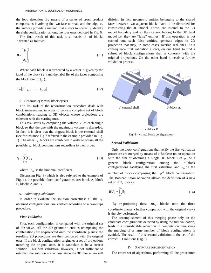
This task starts by computing the volume V of each single
block so that the one with the maximum volume is discarded.
In fact, it is clear that the biggest block is the external shell
(see for instance Fig.7 referred to the example provided in Fig.
1). The other bn blocks are combined in order to obtain all the
possible bc block combinations regardless to their order:
n
k
knb Cc1
, (13)
where knC , is the binomial coefficient.
Discussing Fig. 8 (which is also referred to the example of
Fig. 1), the possible block configurations are: block A, block
B, blocks A and B.
D. Solution(s) validation
In order to evaluate the solution correctness all the bc
obtained configurations are verified according to a two-steps
procedure.
First Validation
First, each configuration is compared with the original set
of 2D views. All the 3D geometric entities (composing the
combination) are re-projected onto the coordinate planes; the
resulting 2D projections are then compared with the original
ones. If the block configuration originates a set of projections
matching the original ones, it is candidate to be a correct
solution. This first validation, however, is not sufficient to
establish the solution correctness since the 3D blocks are still
disjoint; in fact, geometric entities belonging to the shared
faces between two adjacent blocks have to be discarded for
constructing the 3D model. These, are internal to the 3D
model boundary and so they cannot belong to the 3D final
model i.e. they are “false” entities). If this operation is not
carried out, such false entities, generate edges in 2D
projection that may, in some cases, overlap real ones. As a
consequence first validation allows, on one hand, to find a
subset of block configurations that is coherent with the
original projections. On the other hand it needs a further
validation process.
a) external shell. b) block A.
c) block B
Fig. 8 – virtual block configurations.
Second Validation
Only the block configurations that verify the first validation
procedure are merged by means of a Boolean union operation
with the aim of obtaining a single 3D block. Let be a
generic block configuration among the block
configurations satisfying the first validation and n be the
number of blocks composing the th block configuration.
The Boolean union operation allows the definition of a new
set of BU blocks:
n
i
ibBU1
(14)
By re-projecting these BU blocks onto the three
coordinate planes a further comparison with the original views
is thereby performed.
The accomplishment of this merging phase only on the
candidate configurations detected by using the first validation,
leads to a considerable reduction in computation time since
the merging of a large number of block configurations is
avoided. The result of this second validation is the set of the
correct 3D solutions (Fig.8).
IV. SOFTWARE IMPLEMENTATION
The entire set of algorithms, performing all the procedures
INTERNATIONAL JOURNAL OF MECHANICS
Issue 2, Volume 5, 2011 97
described in section III, is implemented by means of two
software packages, Matlab® and Rhinoceros®. The first one,
which is widely spread in the scientific community, is mainly
used as a mathematical kernel, while Rhinoceros® (by means
of custom scripts) allows to easily translate Matlab® output
results into 3D models and operate them according to the
described procedure.
CONCLUSIONS
In this work an orderly, unambiguous and automatic
procedure covering the necessary steps for retrieving 3D
models from mechanical drawings is provided. Since the
intent was to afford an as clear as possible, guided, procedure
for 3D reconstruction, mathematical description has been fully
developed referring to the simplest case of polyhedral objects.
The proposed procedures, inspired by state of the art works,
can be effectively contribute to speed-up the possible
implementation of methodologies confronting the 3D
reconstruction problem. In fact, the procedure has been
designed like an open source tool for researchers who want to
deal with the “reconstruction problem”; in other word strictly
following the proposed procedure steps, researchers will be
able to quickly introduce themselves in the reconstruction
problem field.
In order to assess the effectiveness of the devised
procedures, these have been implemented and tested on a
number of case studies.
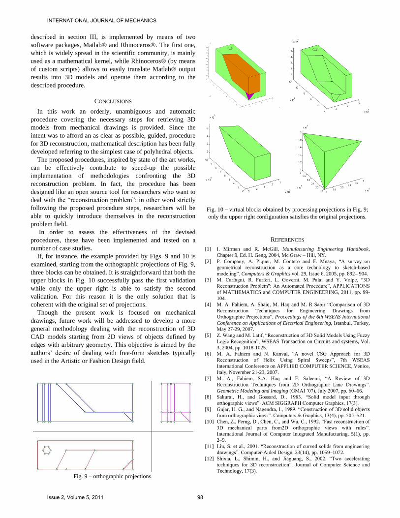
If, for instance, the example provided by Figs. 9 and 10 is
examined, starting from the orthographic projections of Fig. 9,
three blocks can be obtained. It is straightforward that both the
upper blocks in Fig. 10 successfully pass the first validation
while only the upper right is able to satisfy the second
validation. For this reason it is the only solution that is
coherent with the original set of projections.
Though the present work is focused on mechanical
drawings, future work will be addressed to develop a more
general methodology dealing with the reconstruction of 3D
CAD models starting from 2D views of objects defined by
edges with arbitrary geometry. This objective is aimed by the
authors’ desire of dealing with free-form sketches typically
used in the Artistic or Fashion Design field.
Fig. 9 – orthographic projections.
Fig. 10 – virtual blocks obtained by processing projections in Fig. 9;
only the upper right configuration satisfies the original projections.
REFERENCES
[1] I. Mirman and R. McGill, Manufacturing Engineering Handbook,
Chapter 9, Ed. H. Geng, 2004, Mc Graw – Hill, NY.
[2] P. Company, A. Piquer, M. Contero and F. Mnaya, “A survey on
geometrical reconstruction as a core technology to sketch-based
modeling”. Computers & Graphics vol. 29, Issue 6, 2005, pp. 892– 904.
[3] M. Carfagni, R. Furferi, L. Governi, M. Palai and Y. Volpe, “3D
Reconstruction Problem": An Automated Procedure”, APPLICATIONS
of MATHEMATICS and COMPUTER ENGINEERING, 2011, pp. 99-
104.
[4] M. A. Fahiem, A. Shaiq, M. Haq and M. R Sabir “Comparison of 3D
Reconstruction Techniques for Engineering Drawings from
Orthographic Projections”, Proceedings of the 6th WSEAS International
Conference on Applications of Electrical Engineering, Istanbul, Turkey,
May 27-29, 2007.
[5] Z. Wang and M. Latif, “Reconstruction of 3D Solid Models Using Fuzzy
Logic Recognition”, WSEAS Transaction on Circuits and systems, Vol.
3, 2004, pp. 1018-1025.
[6] M. A. Fahiem and N. Kanval, “A novel CSG Approach for 3D
Reconstruction of Helix Using Spiral Sweeps”, 7th WSEAS
International Conference on APPLIED COMPUTER SCIENCE, Venice,
Italy, November 21-23, 2007.
[7] M. A., Fahiem, S.A. Haq and F. Saleemi, “A Review of 3D
Reconstruction Techniques from 2D Orthographic Line Drawings”.
Geometric Modeling and Imaging (GMAI ’07), July 2007, pp. 60–66.
[8] Sakurai, H., and Gossard, D., 1983. “Solid model input through
orthographic views”. ACM SIGGRAPH Computer Graphics, 17(3).
[9] Gujar, U. G., and Nagendra, I., 1989. “Construction of 3D solid objects
from orthographic views”. Computers & Graphics, 13(4), pp. 505–521.
[10] Chen, Z., Perng, D., Chen, C., and Wu, C., 1992. “Fast reconstruction of
3D mechanical parts from2D orthographic views with rules”.
International Journal of Computer Integrated Manufacturing, 5(1), pp.
2–9.
[11] Liu, S. et al., 2001. “Reconstruction of curved solids from engineering
drawings”. Computer-Aided Design, 33(14), pp. 1059–1072.
[12] Shixia, L., Shimin, H., and Jiaguang, S., 2002. “Two accelerating
techniques for 3D reconstruction”. Journal of Computer Science and
Technology, 17(3).
INTERNATIONAL JOURNAL OF MECHANICS
Issue 2, Volume 5, 2011 98
[13] Inoue, K., Shimada, K., and Chilaka, K., 2003. “Solid Model
Reconstruction of Wireframe CAD Models Based on Topological
Embeddings of Planar Graphs”. Journal of Mechanical Design, 125(3),
September, pp. 434–442.
[14] Zhang, A., Xue, Y., Sun, X., Hu, Y., Luo, Y.,Wang, Y., Zhong,
S.,Wang, J., Tang, J., and Cai, G., 2004. Reconstruction of 3D
Curvilinear Wireframe Model from2D Orthographic Views.
[15] Gong, J., Zhang, G., Zhang, H., and Sun, J., 2006. “Reconstruction of
3D curvilinear wire-frame from three orthographic views”. Computers &
Graphics, 30(2), pp. 213–224.
[16] M. Wesley and G. Markowsky, “Fleshing out wire frames”. IBM
Journal of Research and Development, Vol. 24, Issue 5, 1980, pp. 582–
597.
[17] M. Wesley and G. Markowsky, “Fleshing out projections”. IBM Journal
of Research and Development, Vol. 25, Issue 6, 1981, pp. 934–954.
[18] R. Furferi, L. Governi, M. Palai and Y. Volpe, “From 2D Orthographic
views to 3D Pseudo-wireframe: An Automatic Procedure”. International
Journal of Computer Applications IJCA Vol. 5 Issue 6, 2010, pp. 12–17.
[19] Q. Yan, C. Chen and Z. Tang, “Efficient algorithm for the reconstruction
of 3D objects from orthographic projections”. Computer-Aided Design,
Vol. 26, Issue 9, 1994, pp. 699–717.
Furferi R., PhD in Machine design and
Construction (2005) - University of Florence,
Italy. Graduated M.Sc. in Mechanical
Engineering - University of Florence. After
working as a post-doctoral researcher at the
Department of Mechanics and Industrial
Technologies of the University of Florence, in
2008 he assumed a Faculty position as Assistant
Professor for the course “Mechanical Drafting”.
His main Scientific interests are: development of
artificial vision systems for industrial and textile
control, artificial neural networks, colorimetry, reverse engineering and rapid
prototyping. He is author and co-author of many publications printed in
journals and presented on international conferences. Some latest publications
described methods for color assessment of textiles, algorithms for 3D
reconstruction of objects from orthographic views and ANN-based systems
for industrial process. Dr. Furferi is Technical Editor for some journals:
Journal of Applied Sciences, Journal of Artificial Intelligence and
International Journal of Manufacturing Systems.
Governi L. PhD in Machine design and
Construction (2002) - University of Florence, Italy.
Graduated M.Sc. in Mechanical Engineering -
University of Florence. After working as a post-
doctoral researcher at the Department of Mechanics
and Industrial Technologies of the University of
Florence, in 2005 he assumed a Faculty position as
Assistant Professor for the courses of “Reverse
Engineering” and “Design and modeling methods”.
His main scientific interests are: machine vision and
reverse engineering, colorimetry, tools and methods
for product design and development. He is author and co-author of many
publications printed in international journals and participated to a number of
international conferences. Some latest publications described techniques
oriented towards the 3D reconstruction from orthographic views, vision-based
product and process assessment and spline-based approximation of point
clouds.
Volpe Y. PhD in Machine design and Construction (2006) - University of
Florence, Italy. Graduated M.Sc. in Mechanical Engineering - University of
Florence. He is currently working as a post-
doctoral researcher at the Department of
Mechanics and Industrial Technologies -
University of Florence. He is also Adjunct
Professor of the course “Computational Graphics”
from the Engineering Faculty of the University of
Florence. His main scientific interests are:
Computer Aided Design, Image Processing,
Virtual Prototyping, FE simulation, Reverse
Engineering and Rapid Prototyping. He is author
and co-author of many publications printed in
international journals and participated to a number of international
conferences. Some latest publications described techniques for comfort-
oriented design, machine vision-based systems for industrial processes and
spline-based approximation of point clouds.
Palai M. PhD candidate in Machine design and
Construction - University of Florence, Italy.
Graduated M.Sc. in Mechanical Engineering -
University of Florence. His Doctorate Research
deals with 2D to 3D conversion, Reverse
Engineering and Rapid Prototyping. He is author
and co-author of many publications printed in
international journals and participated to a number
of international conferences. Some latest
publications described techniques for comfort-
oriented design, machine vision-based systems for
industrial processes and spline-based approximation of point clouds.
INTERNATIONAL JOURNAL OF MECHANICS
Issue 2, Volume 5, 2011 99


![System Mechanical Drawings - Horiba · 2019. 10. 7. · System Mechanical Drawings.44 [11.1] 2X 2.19 [55.6].44 [11.1] 2X 2.06 [52.4] 1.81 [46.1] 5.56 [141.3] 3.47 [88.2] 1.96 [49.8]](https://img.pdfslide.us/doc/110x75/60fe09ae4a7cf26571276ecd/system-mechanical-drawings-horiba-2019-10-7-system-mechanical-drawings44.jpg)