Embed Size (px)
Citation preview

3D Motion Determination Using µIMU And Visual Tracking
14 May 2010
Centre for Micro and Nano Systems
The Chinese University of Hong Kong
Supervised by Prof. LiLam Kin Kwok, Mark

Outline
• Brief summary of previous works
• Detail of Visual Tracking System (VTS)- Perspective Camera Model- Procedure of Pose Estimation
• Current Results of VTS
• Conclusion
• Future Plan

Previous Works
• Implement Harris Corner Finding Algorithm- Automatic finding good features
• Improve the performance of LK Tracking Method- Reduce the noise generated by inconstant lighting
• Find some information about high speed camera (>60fps)

Previous Works

Detail of Visual Tracking System
Select ROI fromcaptured image
Extract Good Features(Harris Algorithm)
Motion Tracking(LK Tracking Method)
Pose Estimation
Position and Orientation(Camera Coordinate)
CoordinateTransformation
Final Pose of Camera
(World Coordinate)

Perspective Camera Model
Optical Axis
Square Grid
Image Plan
f
li
P1
P3
P2
P4
p1p2
p3 p4
C
C: Optical Center
f : Focal Length
li : Distance between 3D feature points and the optical center
Pi : 3D Feature Points on the square grid
pi : Corresponding 2D projected image points
cy
cx
cz
{ C }
wy
wx
wz
{ W }
{ W } : World Coordinate
{ I } : Image Coordinate
{ C } : Camera Coordinate
v
u{ I }

Perspective Camera Model
• Relationship between image point and 3D scene point
Image Plan
Optical Axis
Scene
Optical Center
f
cZ
cx
cX
z
x{ C }

Pose Estimation Procedure
Calibrate camera(obtain interior parameter)
Target DimensionTarget Image
Step 1:
Calibration and Measurement
Calculate distancebetween
target and camera
Step 2:
Recover Pose of Camera
( Respect to Camera Coordinate)
CalculateTransformation Matrix
Step 3:
Recover Transformation Matrix
between Camera to World Coordinate
Final Pose
Step 4:
Transform the coordinate to
World Coordinate
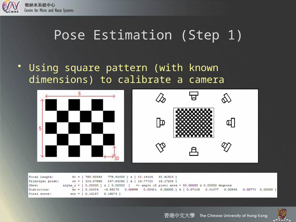
Pose Estimation (Step 1)
• Using square pattern (with known dimensions) to calibrate a camera
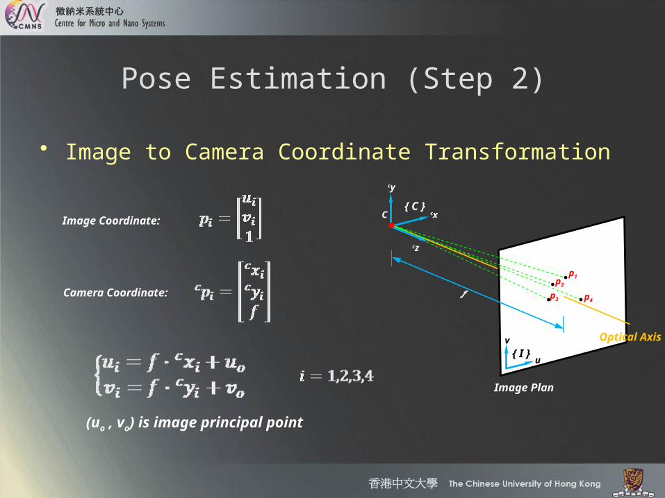
Pose Estimation (Step 2)
• Image to Camera Coordinate Transformation
Image Coordinate:
Camera Coordinate:
Image Plan
f
p1p2
p3 p4
C
cy
cx
cz
{ C }
v
u{ I }
(uo , vo) is image principal point
Optical Axis

• Areas of triangles (Given):
• Volumes of tetrahedra:
• Use unit vector cui to represent cPi
Pose Estimation (Step 2)
C
cy
cx
cz
{ C }
P1
P3
P2
P4
hcP1
cP2cP4
cP3
cui
(From Step 1)

Pose Estimation (Step 2)
• Use vectors to calculate Volume:
• Express d2, d3, d4 as a function of d1:
C
cy
cx
cz
{ C }
P1
P3
P2
P4
hcP1
cP2cP4
cP3
cui

Pose Estimation (Step 2)
• Use a line segment s1k to compute squared distance:
• Use parametric representation and simplify
C
cy
cx
cz
{ C }
P1
P2
cP1
cP2
cu1 cu2
s12

Pose Estimation (Step 2)
• Substitute d1 into the following equation to obtain the 3D coordinates of the feature points:

• Transformation Matrix wTo is given
• Transformation matrix oTc can be obtained by step 2
Pose Estimation (Step 3)
cycx
cz
{ C }
wy
wx
wz{ W }
oy
ox
oz { O }
wTo
oTc
{ W } : World Coordinate
{ O } : Object Coordinate
{ C } : Camera Coordinate
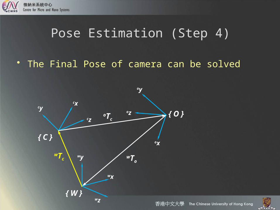
Pose Estimation (Step 4)
• The Final Pose of camera can be solved
cycx
cz
{ C }
wy
wx
wz{ W }
oy
ox
oz { O }
wTo
oTc
wTc

Current Results of VTS
• Experimental Setup
Motion Recording
Computer
Webcam
Feature
Ruler

Current Results of VTS

Conclusion
• Heavily depend on image points- Increase image resolution (Now using 640 X 480 pixels)
• Use some optimization methods to increase accuracy- Gauss-Newton Line search method

Future Plan
• Develop this method and test the performance
• Try to fuse the data with the µIMU data
• Develop the optimization method after finishing data fusion

Reference
[1] Abidi M.A. , Chandra T., “A new efficient and direct solution for estimation using quadrangular targets: algorithm and evaluation,” IEEE transactions on pattern analysis and machine intelligence, Vol.17, No.5, pp.534-538, 1995.
[2] Abidi M.A. , Chandra T., “Pose estimation for camera calibration and landmark tracking,” IEEE International Conference on Robotics and Automation, 2009.
[3] Forsyth Ponce, “Computer Vision: A Modern Approach,” Prentice Hall, 2003

Thanks for your attention