Embed Size (px)
Citation preview

COMOS
Lifecycle3D Integration Administration
Operating Manual
11/2013A5E32076120-AA
Publisher 1
COMOS PDMS Integration 2
COMOS 3D viewing 3
References 4

Legal informationWarning notice system
This manual contains notices you have to observe in order to ensure your personal safety, as well as to prevent damage to property. The notices referring to your personal safety are highlighted in the manual by a safety alert symbol, notices referring only to property damage have no safety alert symbol. These notices shown below are graded according to the degree of danger.
DANGER
indicates that death or severe personal injury will result if proper precautions are not taken.
WARNING
indicates that death or severe personal injury may result if proper precautions are not taken.
CAUTION
indicates that minor personal injury can result if proper precautions are not taken.
NOTICEindicates that property damage can result if proper precautions are not taken.If more than one degree of danger is present, the warning notice representing the highest degree of danger will be used. A notice warning of injury to persons with a safety alert symbol may also include a warning relating to property damage.
Qualified PersonnelThe product/system described in this documentation may be operated only by personnel qualified for the specific task in accordance with the relevant documentation, in particular its warning notices and safety instructions. Qualified personnel are those who, based on their training and experience, are capable of identifying risks and avoiding potential hazards when working with these products/systems.
Proper use of Siemens productsNote the following:
WARNING
Siemens products may only be used for the applications described in the catalog and in the relevant technical documentation. If products and components from other manufacturers are used, these must be recommended or approved by Siemens. Proper transport, storage, installation, assembly, commissioning, operation and maintenance are required to ensure that the products operate safely and without any problems. The permissible ambient conditions must be complied with. The information in the relevant documentation must be observed.
TrademarksAll names identified by ® are registered trademarks of Siemens AG. The remaining trademarks in this publication may be trademarks whose use by third parties for their own purposes could violate the rights of the owner.
Disclaimer of LiabilityWe have reviewed the contents of this publication to ensure consistency with the hardware and software described. Since variance cannot be precluded entirely, we cannot guarantee full consistency. However, the information in this publication is reviewed regularly and any necessary corrections are included in subsequent editions.
Siemens AGIndustry SectorPostfach 48 4890026 NÜRNBERGGERMANY
A5E32076120-AAⓅ 10/2013 Technical data subject to change
Copyright © Siemens AG 2013.All rights reserved

Table of contents
1 Publisher.......................................................................................................................................................7
2 COMOS PDMS Integration...........................................................................................................................9 2.1 Configuring the COMOS PDMS interface.....................................................................................9 2.1.1 Install.............................................................................................................................................9 2.1.1.1 Local..............................................................................................................................................9 2.1.1.2 Citrix Client .................................................................................................................................10 2.1.1.3 Citrix Server ................................................................................................................................11 2.1.1.4 Citrix client (silent mode).............................................................................................................12 2.1.1.5 INI file..........................................................................................................................................13 2.1.1.6 Example text file for installation in silent mode............................................................................14 2.1.2 Specifying the path to the INI file.................................................................................................15 2.1.3 Activating the COMOS PDMS interface......................................................................................15 2.1.4 Specifying interface-relevant directories.....................................................................................16 2.1.5 UDAs...........................................................................................................................................16 2.2 Configuration basics for interface operations..............................................................................17 2.2.1 Interface objects..........................................................................................................................17 2.2.2 Classes and subclasses..............................................................................................................18 2.2.2.1 Class definition objects................................................................................................................19 2.2.2.2 Subclass definition objects of classes "Cable" and "Tagged item".............................................19 2.2.2.3 Subclass definition objects of the "Query" class.........................................................................20 2.2.2.4 Subclass definition objects of the "Document" class...................................................................21 2.2.2.5 "Folders for class/subclass definitions" object.............................................................................22 2.2.3 Name mapping............................................................................................................................23 2.2.3.1 Level rules of name mapping......................................................................................................24 2.2.3.2 Structural behavior......................................................................................................................25 2.2.4 Working with area pipes..............................................................................................................25 2.2.5 Name directory............................................................................................................................26 2.2.6 String Parameters.......................................................................................................................27 2.2.7 Restrictions for owners................................................................................................................28 2.2.8 Model information........................................................................................................................29 2.2.9 Pre/post executables...................................................................................................................30 2.2.10 Character mapping......................................................................................................................30 2.2.11 Units mapping.............................................................................................................................30 2.2.12 ZONE mapping and SITE mapping.............................................................................................31 2.2.13 Operation messages...................................................................................................................31 2.2.14 Connection information...............................................................................................................32 2.3 Configuring interface operations.................................................................................................33 2.3.1 Workflow......................................................................................................................................33 2.3.2 Maintaining the standard table for PDMS element types............................................................36 2.3.3 Standard tables for classes and subclasses...............................................................................37 2.3.4 Creating the "Folders for class/subclass definitions" object........................................................37 2.3.5 Configuring the "Folders for class/subclass definitions" object...................................................38 2.3.5.1 Activating operation messages...................................................................................................38 2.3.5.2 Defining global variables.............................................................................................................38
3D Integration AdministrationOperating Manual, 11/2013, A5E32076120-AA 3

2.3.5.3 Using pre/post executables.........................................................................................................39 2.3.5.4 Using character mapping............................................................................................................41 2.3.5.5 Using unit mapping......................................................................................................................41 2.3.5.6 Using ZONE mapping and SITE mapping...................................................................................42 2.3.6 Creating a class definition object.................................................................................................43 2.3.7 Creating subclass definition objects............................................................................................44 2.3.8 Configure subclass definition objects of classes "Cable" and "Tagged item".............................45 2.3.8.1 Defining PDMS element types....................................................................................................45 2.3.8.2 Defining structural behavior.........................................................................................................45 2.3.8.3 Defining the base object for the creation of interface objects.....................................................46 2.3.8.4 Restrictions for owners................................................................................................................47 2.3.8.5 Configuring the model.................................................................................................................49 2.3.9 Working with String Parameters in the name directory...............................................................50 2.3.9.1 Structure of a String Parameter...................................................................................................50 2.3.9.2 Configuring String Parameters....................................................................................................51 2.3.9.3 Configuring the "Comos attribute", "PDMS attribute/expression", "GetFunction", and
"SetFunction" columns................................................................................................................55 2.3.10 Configuring site mapping and location mapping in name mapping.............................................57 2.3.10.1 Structure of the tables for unit and location mapping..................................................................57 2.3.10.2 Algorithm for generating a PDMS name......................................................................................57 2.3.10.3 Algorithm for generating a COMOS path name..........................................................................59 2.3.10.4 Algorithm for generating a COMOS object through name mapping............................................60 2.3.10.5 Configuring unit mapping and location mapping.........................................................................61 2.3.10.6 Configuring level rules.................................................................................................................64 2.3.11 Configuring COMOS queries from PDMS...................................................................................64 2.3.11.1 Workflow......................................................................................................................................64 2.3.11.2 Creating and configuring COMOS queries..................................................................................65 2.3.11.3 Creating definition objects for queries.........................................................................................65 2.3.11.4 Configuring a subclass definition object for queries....................................................................66 2.3.12 Configuring "Import DocLinks"....................................................................................................68 2.3.12.1 Defining the entry for the target document in PDMS...................................................................68 2.3.12.2 Configuring "Import DocLinks" in COMOS..................................................................................68 2.3.12.3 Defining the String Parameter for the document name...............................................................69 2.3.12.4 Configuring general settings........................................................................................................69 2.3.12.5 Defining restrictions for owners for draft objects.........................................................................70 2.3.13 Synchronizing settings................................................................................................................70 2.3.14 Importing AVEVA design templates............................................................................................71 2.3.15 Configuring COMOS interface objects........................................................................................72 2.3.15.1 Assigning the class, subclass, and PDMS element type.............................................................72 2.3.15.2 Overwriting the inherited model information................................................................................73 2.4 Communication process..............................................................................................................75 2.4.1 Communication modes................................................................................................................75 2.4.2 COMOS to PDMS.......................................................................................................................76 2.4.3 PDMS to COMOS.......................................................................................................................78 2.5 Configuring the COMOS PDMS engineering interface...............................................................80 2.5.1 Entering COMOS PDMS engineering interface as an add-in......................................................80 2.5.2 Restricting COMOS objects for the COMOS PDMS engineering interface.................................80 2.5.2.1 Creating queries..........................................................................................................................81 2.5.2.2 Assigning queries to users..........................................................................................................81 2.5.3 Using classes and subclasses....................................................................................................81 2.5.4 Feedback mode...........................................................................................................................82
Table of contents
3D Integration Administration4 Operating Manual, 11/2013, A5E32076120-AA

3 COMOS 3D viewing...................................................................................................................................83 3.1 Installing "COMOS Walkinside Integration".................................................................................83 3.2 Activating "COMOS Walkinside Integration" in COMOS.............................................................84 3.3 Activating "COMOS Walkinside Integration" in Walkinside.........................................................85 3.4 Configuring settings for "COMOS Walkinside Integration"..........................................................85 3.5 Configuring navigation.................................................................................................................86 3.5.1 Creating a configuration on the COMOS side.............................................................................86 3.5.2 Creating a configuration on the Walkinside side.........................................................................88 3.5.3 Editing tag scripts........................................................................................................................89 3.5.4 Creating scripts in the script library.............................................................................................92 3.5.5 Working with database-based queries........................................................................................93 3.5.6 Providing link list to users............................................................................................................94 3.6 Configuring the query for exporting COMOS objects..................................................................94
4 References.................................................................................................................................................95 4.1 COMOS PDMS Integration.........................................................................................................95 4.1.1 Structure of the standard table for PDMS element types............................................................95 4.1.2 Structure of the standard table for classes..................................................................................96 4.1.3 Structure of the standard table for subclasses............................................................................96 4.1.4 Attribute properties......................................................................................................................97 4.1.5 Attributes of the "Folders for class/subclass definitions" object..................................................97 4.1.5.1 "General" tab...............................................................................................................................97 4.1.5.2 "Name directory" tab...................................................................................................................98 4.1.5.3 "Pre/post executables" tab..........................................................................................................98 4.1.5.4 "Character mapping" tab.............................................................................................................99 4.1.5.5 "Unit mapping" tab.......................................................................................................................99 4.1.5.6 "Site mapping" and "Zone mapping" tabs...................................................................................99 4.1.6 Attributes of the subclass definition objects of classes "Cable" and "Tagged item"..................100 4.1.6.1 "General" tab.............................................................................................................................100 4.1.6.2 "Name mapping" tab.................................................................................................................101 4.1.6.3 "Restrictions for owners" tab.....................................................................................................101 4.1.6.4 "Model" tab................................................................................................................................101 4.1.6.5 "Name directory" tab.................................................................................................................102 4.1.7 Attributes of the subclass definition objects of the "Query" class..............................................103 4.1.7.1 The "General" tab......................................................................................................................103 4.1.8 Attributes of the subclass definition objects of the "Document" class.......................................104 4.1.8.1 "General" tab.............................................................................................................................104 4.1.8.2 "Restrictions for owners" tab.....................................................................................................105 4.1.8.3 "Name directory" tab.................................................................................................................105 4.1.9 Attributes of the interface objects..............................................................................................105 4.1.9.1 Attributes of the "External 3D Interface" tab..............................................................................105 4.1.10 Attributes of the design template objects..................................................................................106 4.1.10.1 Attributes of the "External 3D Interface" tab..............................................................................106 4.1.11 "PDMS" category.......................................................................................................................107 4.2 COMOS 3D viewing..................................................................................................................108 4.2.1 "Tag Script Editor" window........................................................................................................108 4.2.2 "Walkinside Object Assignment" plugin.....................................................................................109 4.2.3 "COMOS AutoAssign Configuration" plugin..............................................................................111
Table of contents
3D Integration AdministrationOperating Manual, 11/2013, A5E32076120-AA 5

4.2.4 Project properties......................................................................................................................112 4.2.5 Sample scripts...........................................................................................................................112 4.2.5.1 Sub OnProjectOpen(Project).....................................................................................................112 4.2.5.2 "COMOS.C3DView.config" file..................................................................................................113
Table of contents
3D Integration Administration6 Operating Manual, 11/2013, A5E32076120-AA

Publisher 1AVEVA
PDMS is a software product of the AVEVA company and will hereafter be referred to simply as PDMS.
3D Integration AdministrationOperating Manual, 11/2013, A5E32076120-AA 7


COMOS PDMS Integration 22.1 Configuring the COMOS PDMS interface
2.1.1 Install
The following installation modes are available:
● Local installation
● Installation on the Citrix server
● Installation on the Citrix client
● Installation on the Citrix client in silent mode
2.1.1.1 Local
RequirementCOMOS and PDMS are already installed on the computer.
Procedure1. Insert the installation CD and start "setup.exe".
2. Select the "Local" installation mode:
3. Click "Next".
4. Select the installation directory. The initialization file is also stored in this directory.See also chapter INI file (Page 13).
3D Integration AdministrationOperating Manual, 11/2013, A5E32076120-AA 9

5. Specify the PDMS directories: You have the option of changing the default settings for the PDMS directories:
– "PML-Lib":If the "Install PML-Lib" option is activated: The PML-Lib supplied with the installation CD is copied to this folder.
– "Working directory":The path to the directory that will be used for data exchange. This directory can also be specified at a later time in COMOS in the project properties.
– "Configuration directory":The path to the directory that is used to exchange command files. This directory can also be specified at a later time in COMOS in the project properties.
– "Executable":The path to the folder where "TalkToComos.exe" is saved. The Windows environment variable PATH should point to this directory. If not, the directory is attached to the Windows environment variable PATH.
– "Install PML-Lib" option: See above.
– "Register PDMS components" option: Registers the COMOS interface in PDMS. If the option is not enabled, the "DesignAdmin.xml" file in the installation directory of PDMS must be edited to be able to use the interface: Add the following XML node: <string>Comos.PDMSInterface.ComosAddin</string>
6. Click "Next".
7. Select the installation directory.
8. Click the "Install" button to start the installation.During installation, entries are made in the registry and the PDMS-Lib is installed.
9. Click the "Finish" button to complete the installation.
2.1.1.2 Citrix Client
Requirement● PDMS is installed on the Citrix client.
● COMOS is installed or will be installed on the Citrix server.
Procedure1. Insert the installation CD and start "setup.exe".
2. Start by selecting the "Citrix client" installation mode:
3. Click "Next".
4. Select the installation directory. The initialization file is also stored in this directory.See also chapter INI file (Page 13).
COMOS PDMS Integration2.1 Configuring the COMOS PDMS interface
3D Integration Administration10 Operating Manual, 11/2013, A5E32076120-AA

5. Click "Next".
6. Specify the directory into which the COMOS components on the client side of COMOS/PDMS communication are to be copied (COMOS side = the server side, PDMS = the client side):
7. Click "Next".
8. Optionally: Change the default settings of the PDMS directories on the client computer:
– "PML-Lib":If the "Install PML-Lib" option is activated: The PML-Lib supplied with the installation CD is copied to this folder.
– "Working directory":The path to the directory that will be used for data exchange. This directory can also be specified at a later time in COMOS in the project properties.
– "Configuration directory":The path to the directory that is used to exchange command files. This directory can also be specified at a later time in COMOS in the project properties.
– "Executable":The path to the folder where "TalkToComos.exe" is saved. The Windows environment variable PATH should point to this directory. If not, the directory is attached to the Windows environment variable PATH.
– "Install PML-Lib" option: See above.
– "Register PDMS components" option: Registers the COMOS interface in PDMS. If the option is not enabled, the "DesignAdmin.xml" file in the installation directory of PDMS must be edited to be able to use the interface: Add the following XML node: <string>Comos.PDMSInterface.ComosAddin</string>
Click "Next".
9. To start the installation, click "Install".During installation, entries are made in the registry and the PDMS-Lib is installed.
10.Click the "Finish" button to complete the installation.
2.1.1.3 Citrix Server
Requirement● You are working on the Citrix server 4.0.
● COMOS is already installed on the Citrix server.
COMOS PDMS Integration2.1 Configuring the COMOS PDMS interface
3D Integration AdministrationOperating Manual, 11/2013, A5E32076120-AA 11

Procedure1. Insert the installation CD, open the control panel, click "Software", then "CD or Disk", and
select the path to setup.exe. Then start "setup.exe".The start dialog field of the InstallShield Wizard opens.
2. Click "Next".
3. Start by selecting the "Citrix server" installation mode:
4. Then click "Next".
5. Select the installation directory. The initialization file is also stored in this directory.See also chapter INI file (Page 13).
6. Click "Next".
7. Optionally: Change the default settings of the PDMS directories:
– "Working directory" field:The path to the directory that will be used for data exchange. Must point to the same folder that is entered during the Client installation.Input required.
– "Configuration directory" field:The path to the directory that is used to exchange command files. Must point to the same folder that is entered during the Client installation.Input required.
8. Click "Next".
9. Click the "Install" button to start the installation.During the installation entries are made in the registry.
10.Click the "Finish" button to complete the installation.
2.1.1.4 Citrix client (silent mode)Installation in silent mode runs in the background and is controlled by a text file in which the administrator has entered all of the relevant information in advance. You do not need to make any further entries during installation.
RequirementPDMS is installed on the Citrix client.
Procedure1. Create a new text file.
2. Save the file in a local directory.
COMOS PDMS Integration2.1 Configuring the COMOS PDMS interface
3D Integration Administration12 Operating Manual, 11/2013, A5E32076120-AA

3. Enter the following paths in the file:See also chapter Example text file for installation in silent mode (Page 14).
– Line 1: <Path to the installation directory (file location for INI file)>;<0 or 1> 0: If the directory does not exist, it should not be created1: If the directory does not exist, it should be created
– Line 2: <Path to the working directory (communication directory and exchange directory)>
– Line 3: <Path to the configuration directory (document path and configuration path)>
– Line 4: <Path to the PMLLib directory>;<0 or 1>0: The directory is not created; the PMLLib is not copied 1: The directory is created; the PMLLib is copied
– Line 5: <Path to the PDMS installation directory>;<0 or 1>1: COMOS PDMS interface is entered in the PDMS DesignAddins.xml file.0: COMOS PDMS interface is not entered in the PDMS DesignAddins.xml fileIn this case, you must insert the entry manually in order to use the COMOS PDMS interface. See also chapter Entering COMOS PDMS engineering interface as an add-in (Page 80).
4. Use the command line to call the setup with the path to the created text file as a parameter.
ResultThe installation executes the same steps as the client installation. See also chapter Citrix Client (Page 10).
2.1.1.5 INI fileTo guarantee that COMOS and PDMS use the same configuration, the configuration is saved in an initialization file (INI file). This initialization file is created during the installation of COMOS PDMS Interface. COMOS and PDMS use this file for communication and data exchange between COMOS and PDMS during an interface operation.
The complete INI file is in XML format and has the following structure:<ComosPDMSInterfaceConfiguration> <CommunicationFolder path="<path>"/> <ExchangeFolder path="<path>"/> <SubclassesFile path="<path>"/> <TalkToComos path="<path>"/> <Logfile path="<path>"/> <DocumentFolder path="<path>"/> <MTOTransferConfigurationFile path="<path>"/> <StartupFunctionsFile path="<path>"/> <ClientCommandService path="<path>"/> <StartClientCommandService value="<Boolean>"/></ComosPDMSInterfaceConfiguration>The following nodes are included:
COMOS PDMS Integration2.1 Configuring the COMOS PDMS interface
3D Integration AdministrationOperating Manual, 11/2013, A5E32076120-AA 13

Node DescriptionCommunicationFolder ● Mandatory information
● Directory containing the XML files for command exchange. Created automatically, if not already present.
ExchangeFolder ● Mandatory information● Directory containing the XML files that are used for
data exchange. Created automatically, if not already present.
SubclassesFile ● Mandatory information● Path to the Subclasses.xml configuration file
TalkToComos ● Mandatory information● Path to talkToComos.exe
Logfile ● Mandatory information● Path to the log file
DocumentFolder Path to the document directoryIf this path is not specified, you cannot export any documents from the draft module. Created automatically, if not already present.
MTOTransferConfigurationFile Path to file MTOExportSettings.dat. The file name here is an example only; you can choose any file name.If this path is not specified, you cannot transfer any MTO data to COMOS. You can find additional information on this topic in the "COMOS Material Management Administration" manual, keyword "MTOExportSettings.dat".
StartupFunctionsFile Path to the file containing the StartupFunctionsClientCommandService Path to ClientCommandService.exeStartClientCommandService Flag which indicates whether ClientCommandService.exe
is to be executed when AVEVA PDMS startsPossible values:● true● false
See alsoSpecifying the path to the INI file (Page 15)
2.1.1.6 Example text file for installation in silent modeD:\PDMSInterface\;1D:\PDMSInterface\Work\D:\PDMSInterface\Configuration\D:\PDMSInterface\PMLLib\;1D:\AVEVA\Plant\PDMS12.0.SP6\;0
COMOS PDMS Integration2.1 Configuring the COMOS PDMS interface
3D Integration Administration14 Operating Manual, 11/2013, A5E32076120-AA

See alsoCitrix client (silent mode) (Page 12)
2.1.2 Specifying the path to the INI file
Specifying the path to the INI file in COMOS1. Select the "PDMS" category in the project properties.
2. Click the "..." button of the "Initialization file" field.
3. In the file explorer, select the initialization file which was created during installation.
Specifying the path to the INI file in PDMS1. Specify the file location for the initialization file in an environment variable in the evars.bat
file of your PDMS installation.
2. Define the environment variable as follows:set COMOSPDMSINTERFACECONFIGURATION=<path>/<name of ini file>
See alsoINI file (Page 13)
2.1.3 Activating the COMOS PDMS interfaceIn COMOS, you activate the interface on a project-specific basis.
You only need to activate the interface once for each project. The interface remains activated, even in subsequent sessions, until you deactivate it. It only has to be reactivated after it has been deactivated.
To work with COMOS PDMS Interface, you must activate the interface in PDMS every time you restart PDMS. You can find additional information on this topic in the "3D Integration Operation" manual, keyword "Activating COMOS PDMS Interface for PDMS".
Procedure1. Start COMOS.
2. Open the project in which you will work.
3. Open the project properties and go to the "PDMS" category.
4. Activate the "Interface active" option.COMOS PDMS Interface is being activated and made available in the COMOS menu.
COMOS PDMS Integration2.1 Configuring the COMOS PDMS interface
3D Integration AdministrationOperating Manual, 11/2013, A5E32076120-AA 15

Deactivating COMOS PDMS Integration1. Start COMOS.
2. Open the project for which you want to deactivate the interface.
3. Open the project properties and go to the "PDMS" category.
4. Deactivate the "Interface active" option.
2.1.4 Specifying interface-relevant directories
Procedure1. Select the "PDMS" category in the project properties.
2. See also chapter "PDMS" category (Page 107).
3. Set the paths to the individual directories by clicking the "..." button and selecting the required directory in the file explorer.
2.1.5 UDAsTo be able to use the PDMS interface, UDAs must be created in PDMS that contain the connection status, configuration information, and connection information on the COMOS object.
List with necessary UDAsThe following UDAs must be available in PDMS:
● ":ComosUID"Contains the SystemUID of the corresponding COMOS object.
● ":ComosCRefNo"Corresponds to the RefNo of the PDMS object.
● ":ComosStatus"Saves the object status.
● ":ComosName"This is the name of the corresponding COMOS object.
● ":ComosBaseOb"Saves the SystemFullName of the base object of the corresponding COMOS object. During an Export to Comos operation, this base object is used to create the corresponding COMOS object.
● ":ComosSClass"The name of the subclass to which this object belongs.
COMOS PDMS Integration2.1 Configuring the COMOS PDMS interface
3D Integration Administration16 Operating Manual, 11/2013, A5E32076120-AA

Create the UDAsCreate the UDAs in a project-related dictionary database. If no appropriate database is available, create the database with the help of the "!!!FCreateDictDB" macro. The following parameters must be passed to this macro in the form of a string:
● "MDB": Name of the MDB
● "TEAM": Name of the TEAM
● "DictDB": Name of the to be created database
● "DBNumber": Database number (must be specified by the administrator)
This macro does not create an MDB, but a TEAM, insofar this is necessary. Once the database has been created, the macro sets this. If you do not create the database with the macro, set the specified dictionary database to currently active to subsequently create the UDAs in the Lexicon module.
Once you have switched to the Lexicon module, create the UDAs with the !!ITSetComosUDAs macro underneath the UWRL.
2.2 Configuration basics for interface operations
2.2.1 Interface objects
Definition of Interface ObjectsInterface objects are engineering objects which can be processed by the interface operations.
An object counts as an interface object if it has the following properties:
● In COMOS:
– "External 3D interface" tab
– Assignment to a class
– Assignment to a subclass The subclass must not be UNDEF.
– PDMS element type
● In PDMS: UDA ":ComosSClass"
If the devices of your device catalog have these properties, they are processed by COMOS PDMS Interface.
See alsoConfiguring COMOS interface objects (Page 72)
COMOS PDMS Integration2.2 Configuration basics for interface operations
3D Integration AdministrationOperating Manual, 11/2013, A5E32076120-AA 17

2.2.2 Classes and subclasses
DefinitionThere are two groups of classes and subclasses:
1. Classes and subclasses which categorize interface objects
2. Classes and subclasses which are used to configure the execution of an interface operation
Group 1The following classes and their subclasses belong to this group:
● "Cable":Interface objects with this class are used for example as:
– Pipe or pipe branch
– HVAC
– DUCT
– CABLES
● "Tagged item":Interface objects with this class are equivalent to PDMS objects which can be positioned in 3D space.
The subclasses allow you to differentiate the behavior of interface objects of the same class. The subclass determines how an interface object is processed during an interface operation.
Group 2The following classes and their subclasses belong to this group:
● "Query" class and its subclasses: They are used to configure COMOS queries and make them accessible and executable in PDMS.
● "Document" class and its subclasses: A DocLink is generated for the interface object.
Properties of classesClasses have the following properties:
● Classes structure the subclasses.
● The number and name of classes are fixed. They are specified by the following standard table:"Standard tables > Y10 > M27 > A10 > Y10 > M27N00002 > Y10M27N00002A01 Classes"
● A class can have any number of subclasses.
COMOS PDMS Integration2.2 Configuration basics for interface operations
3D Integration Administration18 Operating Manual, 11/2013, A5E32076120-AA

Properties of the subclassesSubclasses have the following properties:
● The function performed by a subclass is determined by the class to which it belongs. See above.
● The number and names of subclasses are specified by the subclass definition objects and are dynamically saved in the following standard table:"Standard tables > Y10 > M27 > A10 > Y10 > M27N00002 > Y10M27N00002A02 Subclasses"
See alsoClass definition objects (Page 19)
2.2.2.1 Class definition objects
FunctionClass definition objects are engineering objects which are located directly below the "Folders for class/subclass definitions" object.
Class definition objects have the following function:
● They represent a class from the following standard table:"Standard tables > Y10 > M27 > A10 > Y10M27N00002 > Y10M27N00002A01 Classes"
● They structure the subclass definition objects.
See alsoCreating a class definition object (Page 43)
Standard tables for classes and subclasses (Page 37)
2.2.2.2 Subclass definition objects of classes "Cable" and "Tagged item"
FunctionThe subclass definition objects of classes "Tagged item" and "Cable" fulfill the following function:
● They represent the subclasses of these classes in the engineering view.
● They are used to save and configure the properties of the corresponding members of this subclass.
COMOS PDMS Integration2.2 Configuration basics for interface operations
3D Integration AdministrationOperating Manual, 11/2013, A5E32076120-AA 19

Defining interface object propertiesOne subclass definition object defines the following properties for all interface objects of this subclass:
● Which PDMS element types is the interface object permitted to have?
● Which base object is used when the interface object is created in COMOS?The user defines two base objects:
– One is used when the interface object is created in the unit tree
– One is used when the interface object is created in the location tree
● What are the structural characteristics of the interface object?
– Is the PDMS interface object connected to a COMOS object from the unit tree or from the location tree?
– Is the COMOS interface object to have a pointer to another COMOS object and is this object located in the unit tree or in the location tree?
● Regarding name mapping: How is the PDMS name of the interface object generated?
● Regarding name mapping: How does the interface for a given PDMS object find the location at which the corresponding COMOS object should be created in the COMOS structure?
● Regarding the name directory: Which values are evaluated by the interface operations when you process the interface object?
● Regarding the name directory: Which PDMS attribute is assigned to which COMOS attribute?
● Regarding the name directory: Which string parameters are available in this subclass?
● Regarding the owner restriction rules: Which conditions does the owner have to fulfill so that an interface object can be created underneath it?
● Which 3D model does the interface object use and how is the object initialized during the export if "Function" is set as design model?
See alsoCreating subclass definition objects (Page 44)
Configure subclass definition objects of classes "Cable" and "Tagged item" (Page 45)
2.2.2.3 Subclass definition objects of the "Query" class
Working with COMOS queries in PDMSThe interface allows users to work with COMOS queries in PDMS. Users have the following options:
● They select a query in PDMS from a range of predefined COMOS queries.
● Optionally: They define filters for the query.
● Optionally: They define the start object.
COMOS PDMS Integration2.2 Configuration basics for interface operations
3D Integration Administration20 Operating Manual, 11/2013, A5E32076120-AA

● They start the query from within PDMS.
● They see the result of the query in PDMS or in an external program such as Excel.
This functionality is implemented with the help of COMOS queries and subclass definition objects of the "Query" class.
The subclass definition objects of the "Query" class define the following:
● Which queries are available in PDMS?
● Which base objects do the objects in the result list have?
● Which is the predefined start object?
● In which output format is the result list is transferred?
See alsoClasses and subclasses (Page 18)
Creating subclass definition objects (Page 44)
Configuring COMOS queries from PDMS (Page 64)
2.2.2.4 Subclass definition objects of the "Document" class
AimThe interface allows users to create DocObjs for draft objects in COMOS.
Requirement:
● The draft objects have a DDNM attribute.
● The DDNM attribute references a design object which is connected to a COMOS object.
● A COMOS document under which the DocObjs are imported has been specified in the draft structure.
FunctionIn the subclass definition objects of the "Document" class, you define all settings which are necessary to create DocObjs for draft objects.
These include:
● Where in the PDMS draft structure do you specify the COMOS document for which the DocObjs are created?As you are able create any number of subclass definition objects, you can configure the interface in such a way that "Import DocLinks" can be started at different levels of the draft structure according to the requirements.
● Are there filter criteria which restrict the COMOS document for which the DocObjs can be created?
COMOS PDMS Integration2.2 Configuration basics for interface operations
3D Integration AdministrationOperating Manual, 11/2013, A5E32076120-AA 21

● Are DocObjs only created for draft objects with names or also for draft objects without names?
● Are there owner restriction rules for the draft objects for which DocObjs are created?
See alsoCreating subclass definition objects (Page 44)
Configuring "Import DocLinks" (Page 68)
Standard tables for classes and subclasses (Page 37)
2.2.2.5 "Folders for class/subclass definitions" objectPath in the database: "@20 > D30 > A20 > Y00R00033 Folders for class/subclass definitions"
FunctionThis object fulfills the following functions:
● At this object, you make general settings which apply to the entire interface and not only to a specific class or subclass.
● The class and subclass definition objects are managed below the object.
● In the context menu of the object, you can save the configuration of the subclass definition objects in a file and refresh the standard table used to save the subclasses.
Overview of the general interface settingsThe following general interface settings are configured in the "Folders for class/subclass definitions" object:
● After which interface operations are feedback signals displayed to users?
● Is site mapping and zone mapping used, and how are they configured?See also chapter ZONE mapping and SITE mapping (Page 31).
● How is character mapping configured?See also chapter Character mapping (Page 30).
● How is unit mapping configured?See also chapter Units mapping (Page 30).
● Have pre/post executables been registered?See also chapter Pre/post executables (Page 30).
● Which global string parameters are there?See also chapter String Parameters (Page 27).
COMOS PDMS Integration2.2 Configuration basics for interface operations
3D Integration Administration22 Operating Manual, 11/2013, A5E32076120-AA

See alsoCreating the "Folders for class/subclass definitions" object (Page 37)
Synchronizing settings (Page 70)
Operation messages (Page 31)
2.2.3 Name mapping
FunctionName mapping fulfills the following functions:
● It generates a PDMS name for a COMOS interface object.The interface uses the PDMS name to identify the PDMS interface object to which the COMOS object is connected.
● It uses the PDMS name of a PDMS interface object to ascertain the path to the COMOS interface object to which the PDMS interface object is connected.
● If the structural behavior of the subclass definition object prescribes that a COMOS interface object references another COMOS object, name mapping derives the referenced object from the PDMS name.
● Optionally: If the COMOS interface object which is to be connected to a PDMS object does not exist yet, name mapping determines the base object used to create it.
● If the owner structure of the COMOS interface object which is to be connected to a PDMS object is incomplete or missing, name mapping specifies which owners are created.
Implementing name mappingName mapping is defined for the subclass definition objects in two tables: Unit mapping and Location mapping.
You find information how the structure of the tables, their configuration, and the algorithm on which name mapping is based in section Configuring site mapping and location mapping in name mapping (Page 57).
Unit mapping and location mappingThe unit tree and the location tree do not usually share the same object structure. This is why it is neccessary to manage two mapping tables:
● Unit mapping: Table which defines name mapping in the unit tree
● Location mapping: Table which defines name mapping in the location tree
COMOS PDMS Integration2.2 Configuration basics for interface operations
3D Integration AdministrationOperating Manual, 11/2013, A5E32076120-AA 23

See alsoStructural behavior (Page 25)
Level rules of name mapping (Page 24)
2.2.3.1 Level rules of name mapping
PurposeYou can define deviations from the standard evaluation model for unit mapping and location mapping.
These deviations are particularly required in the following cases:
● If your project works with an alias structure
● If your project works with different hierarchy depths
Rule "Take alias rather than object"If this rule is activated, the alias structure is used to generate the PDMS names.
If no alias is available, the name or description of the object is used.
Rule "Skip level if data part empty"If this rule is activated, you can map hierarchies of different depths in name mapping. The maximum number of mapping entries in the name mapping is determined by the hierarchy with the deepest level.
If the evaluation of the data item or fixed name of a mapping entry returns an empty string, the process continues with the next mapping entry.
Application example: Your equipment is located in the "Equipment" folder. Only pumps are not directly located in the folder; these are to be found in its "Pumps" subfolder.
Rule "Skip level if unable to create object"If a COMOS object cannot be created because of its configuration - because the potential owner only permits certain elements as subobjects, for example - name mapping jumps to the next mapping entry rather than aborting the process. The entry is processed with the next PDMS name part.
Result: This rule allows you to use name mapping in COMOS to create object structures with hierarchy levels of different depths.
Rule "Use label for fixed name"If this rule is activated, the label of a COMOS object rather than its name is used in the "Fixed name" range.
COMOS PDMS Integration2.2 Configuration basics for interface operations
3D Integration Administration24 Operating Manual, 11/2013, A5E32076120-AA

See alsoConfiguring level rules (Page 64)
Name mapping (Page 23)
2.2.3.2 Structural behavior
PurposeThe structural behavior of a subclass definition object defines the following points:
● Creation mode: Is the COMOS interface object to be connected to the PDMS object located in the unit tree or in the location tree?
● Assign mode: Does the COMOS interface object reference another COMOS object and is the referenced object located in the unit tree or in the location tree?
Depending on how you define the structural behavior, either unit mapping or location mapping is evaluated during name mapping to fulfill one of the following tasks:
● Find or create an interface object in order to connect it with a PDMS object.
● Find or create the COMOS object referenced by the COMOS interface object.
See alsoName mapping (Page 23)
Working with area pipes (Page 25)
Defining structural behavior (Page 45)
2.2.4 Working with area pipes
DefinitionAn area pipe is an object which is generated whenever an interface operation processes an object whose subclass has the following structural behavior:
● Creation mode: "Create in location tree"
● Assign mode: "Assign to object in unit tree"
The aim of this setting is to map multiple PDMS objects to a single COMOS object. For this purpose, the area pipe level is inserted between the PDMS objects and the COMOS object.
Application caseA pipe runs across different zones in PDMS, meaning that there are several pipe objects, but logically these represent the same pipe. There is only one pipe object in the COMOS unit tree.
COMOS PDMS Integration2.2 Configuration basics for interface operations
3D Integration AdministrationOperating Manual, 11/2013, A5E32076120-AA 25

Area pipes are created for the PDMS pipes in the location tree and connected to the PDMS pipes. The area pipes get a reference to the same COMOS pipe object.
PropertiesArea pipes have the following properties:
● Area pipes are connected to the PDMS object.
● Area pipes get a unit link to an interface object from the unit tree.
● The full name of the corresponding PDMS object is written to the "Name" property of the area pipe.In contrast, only the last name part of the PDMS name is written to the name of the referenced unit object. Depending on how the name mapping is configured, the name part can even be truncated before it is written to the "Name" property.
● The data exchange regulated by the string parameters is always carried out from connected object to connected object - that is, between area pipe and PDMS object.
See alsoStructural behavior (Page 25)
2.2.5 Name directory
DefinitionThe name directory is a table in which each line defines a string parameter.
Chapter String Parameters (Page 27) contains detailed information on string parameters.
EvaluationThe name directory is evaluated in the following cases:
● During an interface operation if values are compared, exported or imported. These are usually attribute values.
● If a string parameter is used in a subclass definition object on the "Name mapping" tab to generate one of the following components of a PDMS name part:
– Prefix
– Postfix
– Data item
– Base object
COMOS PDMS Integration2.2 Configuration basics for interface operations
3D Integration Administration26 Operating Manual, 11/2013, A5E32076120-AA
● If objects are filtered in the "Export to Comos" PDMS mask.
● If a string parameter is transferred to a PML function as a parameter. For example, if a String parameter is used in an initialization function in a subclass definition object on the "Model" tab.
2.2.6 String Parameters
DefinitionA String parameter is a variable which returns or processes a string:
● It reads a COMOS value or a fixed string. If the String parameter is configured accordingly, it writes the value to PDMS.
● It reads out a PDMS value or a fixed string. If the String parameter is configured accordingly, it writes the value to PDMS.
AvailabilityThere are two types of String parameters. They differ with regard to their availability:
● Global String parameters:These String parameters are available everywhere in the interface operations area. They are defined at the "Folders for class/subclass definitions" object. In PDMS, global String parameters are evaluated independently of the current element.In COMOS, they are evaluated at the following objects:
– In the project
– In the workset
– At the "Folders for class/subclass definitions" object
● Local String parameters:These String parameters are only available per subclass. They are defined in the subclass definition objects and evaluated at the interface object.
PurposeGlobal String parameters are used for the following purpose:
● To define variables which are globally available in the interface operations area.
● To prevent interface operations from being executed if a COMOS value and a PDMS value defined by the String parameter do not match.
Local String parameters are used for the following purpose:
COMOS PDMS Integration2.2 Configuration basics for interface operations
3D Integration AdministrationOperating Manual, 11/2013, A5E32076120-AA 27

● To define variables which are locally available in a subclass
● To perform one of the following actions during the interface operations:
– Export: To write a COMOS value to PDMS
– Import: To write a PDMS value to COMOS
– Check: To compare a COMOS value with a PDMS value
Without these actions it is not possible to make an assignment between the attributes of an interface object in COMOS and PDMS.
● Optionally: To stop objects from being created for the export if a COMOS value you select at random and a PDMS value you select at random do not match.
See alsoName directory (Page 26)
Working with String Parameters in the name directory (Page 50)
Defining global variables (Page 38)
2.2.7 Restrictions for owners
DefinitionYou can use the restrictions for owners to define company internal or project-specific rules at the subclass definition objects which determine which owners are permitted in PDMS for objects of this subclass.
The interface evaluates the restrictions for owners before it creates an object in PDMS or makes an assignment between a COMOS object and a PDMS object. If an owner violates one of the rules, the object is not exported or no assignment is made.
ExampleThe restrictions for owners allow the following rules to be put in place, for example:
● In PDMS, the exported interface objects are only created under zones whose purpose attribute is set to "TAG".
● In PDMS, pipes and branches are only created under zones whose purpose attribute is set to "PIP".
● In PDMS, the equipment is only created under zones whose purpose attribute is set to "EQU".
COMOS PDMS Integration2.2 Configuration basics for interface operations
3D Integration Administration28 Operating Manual, 11/2013, A5E32076120-AA

2.2.8 Model information
Four model typesThe following model types are available for interface objects:
● Design template:
– The model is defined via a design template. The template has been imported from PDMS to COMOS.
– The user defines one main template and up to five templates for secondary equipment.
● PDMS element:The model of an existing PDMS element is used.
● Function:The model is defined via a PML function.
● None:A box is created.
Possible sources There are three ways of defining which model type an interface object uses:
● The model is inherited from the base object
● The model is taken from the subclass definition object
● The settings inherited from the base object or the subclass definition object are over-defined in the properties of the interface object.
ExportWhen an interface object is exported to PDMS, the model information defined in COMOS is also exported.
The object is displayed in PDMS with the corresponding model.
See alsoConfiguring the model (Page 49)
Overwriting the inherited model information (Page 73)
COMOS PDMS Integration2.2 Configuration basics for interface operations
3D Integration AdministrationOperating Manual, 11/2013, A5E32076120-AA 29

2.2.9 Pre/post executables
DefinitionPre/post executables are user-defined PML functions which are called prior to starting or after completion of an interface operation.
● Pre executables execute steps serving the purpose of initialization and have an effect on the entire interface operation.
● Post executables execute concluding steps.
See alsoUsing pre/post executables (Page 39)
2.2.10 Character mapping
Maintaining the naming conventionSome characters, such as blanks, are not allowed to form part of a PDMS name.
If name mapping generates a PDMS name from within COMOS, the resulting string may contain one or more characters which are not permitted in PDMS.
You define which characters are to replace these illegal characters in PDMS in the character mapping settings of the "Folders for class/subclass definitions" object.
See alsoUsing character mapping (Page 41)
2.2.11 Units mapping
Unit conversionIt may be that an attribute was assigned a different unit in COMOS than in PDMS.
Units mapping enables you to map these units. When an attribute of this type is exported or imported, the attribute value is converted as defined in the units mapping settings.
See alsoUsing unit mapping (Page 41)
COMOS PDMS Integration2.2 Configuration basics for interface operations
3D Integration Administration30 Operating Manual, 11/2013, A5E32076120-AA

2.2.12 ZONE mapping and SITE mapping
Initial situationVia the restrictions for owners, you have the option of specifying that interface objects of a subclass in PDMS are only allowed to be located below sites or zones.
When the "Create selected" interface operation is called, the interface exports the objects of this subclass under the current element.
When the "Create" interface operation is called, the interface does not initially know the ZONE and SITE under which these objects are to be exported.
DefinitionSITE mapping and ZONE mapping are two mapping tables:
● The SITE mapping returns a string: the PDMS name of a SITE
● The ZONE mapping returns a string: the PDMS name of a ZONE
The interface carries out SITE and ZONE mapping in order to determine the SITE and ZONE under which the objects in the selection set are to be exported. If the interface cannot find the SITE and the ZONE in PDMS, the interface object is not exported.
ConditionSITE mapping and ZONE mapping is performed only in the following case:
● SITE mapping and ZONE mapping are activated.
● The "Create" interface operation is called.
● The subclass definition object of the interface object currently being processed stipulates that the object has a ZONE or a SITE as its owner in PDMS.
See alsoUsing ZONE mapping and SITE mapping (Page 42)
2.2.13 Operation messages
DefinitionShort operation messages are available for the following interface operations:
● "Assign"
● "Export" from PDMS and COMOS
● "Refresh"
● "Unassign"
COMOS PDMS Integration2.2 Configuration basics for interface operations
3D Integration AdministrationOperating Manual, 11/2013, A5E32076120-AA 31

If the administrator activates an operation message for these operations, a window opens once the interface operation is complete which contains information regarding the course of the operation for the user.
See alsoActivating operation messages (Page 38)
2.2.14 Connection information
DefinitionA COMOS interface object and a PDMS interface object are connected when their connection information matches.
COMOS object PDMS object"SystemUID" = ":ComosUID""Y00T00012.Y00A01244""PDMS reference number"
= "RefNo"
COMOS object COMOS object"SystemUID" = "Y00T00012.Y00A00730"
"SystemUID"
PDMS object PDMS object"RefNo" = ":ComosCRefNo"":ComosUID" = "SystemUID"
These properties are set during the following interface operations:
● PDMS and COMOS: "Export"
● COMOS: "Export to CE"
● COMOS: "Assign"
Name matchingThe fact that name mapping of a COMOS object generates a name which matches the name of a PDMS object is not sufficient for the two objects to count as connected.
Still, name matching is the assignment criterion for the "Assign > Match Names" interface operation.
COMOS PDMS Integration2.2 Configuration basics for interface operations
3D Integration Administration32 Operating Manual, 11/2013, A5E32076120-AA

2.3 Configuring interface operations
2.3.1 Workflow
Two approachesEither of the two following approaches outlined below are possible for the administration of the interface operations area:
● Task-based administration:
– You start by only making the settings which are necessary for a specific task.
– Then you check your entries by executing the corresponding interface operations.
– After this you configure the next task, and so on.
– You should use task-based administration if you do not have extensive experience of interface administration.
– The following tables describe the task-based approach.
● Object-based administration:
– You start by creating the "Folders for class/subclass definitions" object and, underneath it, the class definition objects and the subclass definition objects. See also chapter Classes and subclasses (Page 18).The interface objects are or have been created by users during project planning.
– You then configure the objects in the following sequence:"Y00R00033 Folders for class/subclass definitions" objectSubclass definition objectsBase objects of the interface objects
– You should only use object-based administration if you have extensive experience of interface administration.
– The structure of the "Administration" chapter focuses on object-based administration.
Workflow for task-oriented administrationThe following tables describe the workflow for task-based administration of the interface operations area:
● Table 1: The basic configuration (configuration of the "Folders for class/subclass definitions" object, the subclass definition objects of the "Cable" and "Tagged item" classes, and the interface objects)
● Table 2: Use of COMOS queries in PDMS
● Table 3: Use of pre/post executables
● Table 4: Importing DocLinks
● Table 5: Importing AVEVA templates
COMOS PDMS Integration2.3 Configuring interface operations
3D Integration AdministrationOperating Manual, 11/2013, A5E32076120-AA 33

Steps marked with "*" must be executed at this point at the latest, but can also be performed beforehand.
Table 2-1 Table 1: Workflow for the basic configuration
Step To be configured element Description1 Interface objects Add the "External 3D Interface" tab to the base data.2 "PDMS element types"
standard tableOptionallyEnter more element types.
3 Folders for class/subclass definitions
Create the "Folders for class/subclass definitions" object.
4 Class definition objects Create the class definition objects.5 Subclass definition objects For each class definition object:
Create the subclass definition objects.6 Subclass definition objects of
classes "Cable" and "Tagged item"
For each subclass definition object:● Defining the structural behavior● Defining the PDMS element types● Restrictions for owners:
– Define the element type of the owner– Optionally: Define more restriction rules
● Optionally: Define local variables in the name directory
● Define site mapping and location mapping● Optionally: Define the level rules● Define the model information
7 Interface objects Optionally: Configure the "External 3D interface" tab in the base data
8* Folders for class/subclass definitions
This can already be done after step 3● Define character mapping● If you plan to use "Export", not only from "Export to
CE": Define site and zone mapping● Optionally: Defining global variables● Optionally: Activate the operation messages
9 Folders for class/subclass definitions
Synchronize the settings between COMOS and PDMS
10 Test settings:● In COMOS:
Run "PDMS > 3D-View > Select > By Name":– If the object is found in PDMS: Run "PDMS > Assign> Selected object".– If the object is not found in PDMS: Run "PDMS > Export" and check the generated
name in PDMS.● In PDMS:
Run "Comos > CE > Navigate".11* Folders for class/subclass
definitionsThis can even be carried out after step 3.Define unit mapping.
COMOS PDMS Integration2.3 Configuring interface operations
3D Integration Administration34 Operating Manual, 11/2013, A5E32076120-AA

Step To be configured element Description12* Subclass definition objects of
classes "Cable" and "Tagged item"
This can already be done after step 5In the name directory, define how values are mapped to one another in COMOS and PDMS.
13 Folders for class/subclass definitions
Synchronize the settings between COMOS and PDMS.
14 Use the following interface operations to test the settings in COMOS:● "Refresh"● "Custom Refresh"● "Check status"● "Export" (with attribute values)
17* Subclass definition objects of classes "Cable" and "Tagged item"
This can already be done after step 6."General" tab: Specify the base objects for creating objects.
18 "Folders for class/subclass definitions" object
Synchronize the settings between COMOS and PDMS.
19 Use the "Export" interface operation to test the settings in PDMS.
Table 2-2 Table 2: Workflow for the use of COMOS queries in PDMS:
Step To be configured element DescriptionAfter step 5 in the basic configuration or later1 Queries Create and configure the main queries that are called
from within PDMS.If applicable, create and configure start queries for the main queries.
2 Subclass definition objects of the "Query" class
Configure the subclass definition objects.
3 "Folders for class/subclass definitions" object
Synchronize the settings between COMOS and PDMS.
4 Test the settings in PDMS in the "Query Comos data" window.
Table 2-3 Table 3: Workflow for the use of pre/post executables
Step To be configured element DescriptionAfter step 3 and prior to step 10 of the basic configuration1 PML functions Declare and implement PML functions.2 "Folders for class/subclass
definitions" objectRegister PML functions from step 1 as pre/post executables.
3 "Folders for class/subclass definitions" object
Synchronize the settings between COMOS and PDMS.
4 Test the settings by executing the interface operation for which you registered a PML function as pre/post executables.
COMOS PDMS Integration2.3 Configuring interface operations
3D Integration AdministrationOperating Manual, 11/2013, A5E32076120-AA 35

Table 2-4 Table 4: Importing DocLinks
Step To be configured element DescriptionAfter step 10 of basic configuration, since the connection between COMOS objects and PDMS objects exists at this point in time.1 Draft structure in PDMS Specify the attribute or the UDA for the name of the
COMOS document.2 Subclass definition objects of
the "Document" classConfigure
3 Test the settings as follows:● Create a document in COMOS● Enter the name of the document in PDMS in the attribute defined in step 1 or the UDA● Run the "Import DocLinks" operation in PDMS
Table 2-5 Table 5: Importing AVEVA templates
Step To be configured element DescriptionIf you are using design templates to generate the model: Before step 6 of basic configuration.1 Base object node
"@20 > D30 > A30 > Y00R00038 Objects for design template structure"
Call the "Update design templates" command from the context menu of the node.
2 GType folder Assign the GType folder references created in the base data in step 1 to the device catalog.
2.3.2 Maintaining the standard table for PDMS element types
PurposeThe following standard table is supplied with the database:
"Standard tables > @40 > Y00 > A10 > C10 > Y00N00465 PDMS element types"
The most important PDMS element types are listed in the standard table.
You can expand the standard table:
● By adding missing PDMS element types
● PDMS Version 12 and higher: By means of user-defined PDMS element types
See alsoStructure of the standard table for PDMS element types (Page 95)
COMOS PDMS Integration2.3 Configuring interface operations
3D Integration Administration36 Operating Manual, 11/2013, A5E32076120-AA

2.3.3 Standard tables for classes and subclasses
System-internal managementThe standard tables in which classes and subclasses are listed are managed system-internally in the engineering projects. This means that you are not permitted to edit the standard tables in the engineering project.
You may edit the standard table in the base project.
Standard table for classesYou find the standard table in the following node:
"Standard tables > Y10 > M27 > A10 > Y10M27N00002 > Y10M27N00002A01 Classes"
Standard table for subclassesYou find the standard table in the following node:
"Standard tables > Y10 > M27 > A10 > Y10M27N00002 > Y10M27N00002A02 Subclasses"
The standard table is dynamically updated: When you call the "PDMS > Save subclasses" context command at the "Folders for class/subclass definitions" folder, COMOS synchronizes the structure of the subclass definition objects underneath the class definition objects with the entries of the standard table.
See alsoStructure of the standard table for classes (Page 96)
Structure of the standard table for subclasses (Page 96)
2.3.4 Creating the "Folders for class/subclass definitions" objectIn the database supplied, you create the object directly underneath the project root.
ProcedureCreate the "Folders for class/subclass definitions" object via the "New" entry in the context menu.
NOTICE
If you create the folder using drag&drop from the base data, enter the following value in the "Name" property: "Y00R00033"
COMOS PDMS Integration2.3 Configuring interface operations
3D Integration AdministrationOperating Manual, 11/2013, A5E32076120-AA 37

See alsoConfiguring the "Folders for class/subclass definitions" object (Page 38)
"Folders for class/subclass definitions" object (Page 22)
2.3.5 Configuring the "Folders for class/subclass definitions" object
2.3.5.1 Activating operation messages
RequirementYou have created the "Folders for class/subclass definitions" object in the engineering data. See also chapter Creating the "Folders for class/subclass definitions" object (Page 37).
ProcedureTo activate/deactivate operation messages, proceed as follows:
1. Open the properties of the "Folders for class/subclass definitions" object.
2. Select the "Attributes > General" tab.
3. Search for the "Operation messages" control group.The control group contains a table with the following columns:
– "Operation" column: Interface operations for which operation messages are available
– "Show information" column: To activate/deactivate operation messages
4. Select an entry from the lists in the "Show information" column.Possible values:
– "Yes": Activates operation messages for the corresponding operation based on the row you have selected.
– "No": Operation messages are deactivated for this operation.
See alsoOperation messages (Page 31)
2.3.5.2 Defining global variables
RequirementYou have created the "Folders for class/subclass definitions" object in the engineering data. See also chapter Creating the "Folders for class/subclass definitions" object (Page 37).
COMOS PDMS Integration2.3 Configuring interface operations
3D Integration Administration38 Operating Manual, 11/2013, A5E32076120-AA

ProcedureYou define global variables at the "Folders for class/subclass definitions" object, on the "Name directory" tab.
When defining global variables, proceed in exactly the same way as when defining a local variable in a String parameter at the subclass definition objects. See also chapter Working with String Parameters in the name directory (Page 50).
Structure of the "Name directory" tableThe global variables are defined in the "Name directory" table. The table structure is virtually identical to the one for the subclass definition objects.
Differences:
● No COMOS unit
● No SetFunction
● Only one flag: "Rule"
As no exchange of values is defined in the name directory of the "Folders for class/subclass definitions" object, only global variables, there is no SetFunction and only the "Rule" flag.
Using the "Rule" flagIf you activate the "Rule" flag, you have to configure the String parameter in such a way that it returns both a COMOS value and a PDMS value.
Result: The interface compares the two values before every interface operation and only executes the operation if the values are identical.
See also"Name directory" tab (Page 98)
2.3.5.3 Using pre/post executables
RequirementYou have created the "Folders for class/subclass definitions" object in the engineering data. See also chapter Creating the "Folders for class/subclass definitions" object (Page 37).
COMOS PDMS Integration2.3 Configuring interface operations
3D Integration AdministrationOperating Manual, 11/2013, A5E32076120-AA 39

ProcedureTo execute a PML function before an interface operation is executed or after it has been completed, proceed as follows:
1. Declare the PML function.
– Signature:If "Uses query" = "Yes"!!NamePMLFunktion(!InterfaceOp is String, !config is Boolean, !arg1 is String, !arg2 is String, ...)If "Uses query" = "No"!!NamePMLFunktion(!InterfaceOp is String, !arg1 is String, !arg2 is String, ...)
– Parameter InterfaceOp: The name of the interface operation before or after which the PML function is executed
– Parameter !config: Required only if you select the value "Yes" in the "Before call" or "After call" table in the "Uses query" column.
– Parameter arg1, arg2, ...: Name of any number of global String parameters, optional
2. Implement the PML function.
3. Open the properties of the "Folders for class/subclass definitions" object.
4. Go to the "Attributes > Pre/Post executables" tab.
5. If the PML function is executed before the start of the interface operation, register it in the "Pre executables" table.If the PML function is executed after completion of the interface operation, register it in the "Post executables" table.To register a PML function for an interface operation, proceed as follows:
– "Executable" column:Enter the name of the PML function from step 1.
– "Query" column:Select "Yes" if the PML function is to execute a COMOS query. The function must have been implemented accordingly.The PML function is then called twice. Initially with !config = TRUE: Implement the function in such a way that the config file for the query is configured in the function and send to COMOS. COMOS then executes the query and the function retrieves the results. For the second time with !config = FALSE: Function operates with resultsSelect "No" if the PML function does not use a COMOS query.
– "Export", "Assign", "Refresh", "Check status", "Import ", "MTO import" columns:Select "Yes" to register the PML function for these interface operations.
You can find additional information on this topic in the "3D Integration Operation" manual, keyword "List of interface operations and internal names".
COMOS PDMS Integration2.3 Configuring interface operations
3D Integration Administration40 Operating Manual, 11/2013, A5E32076120-AA

See also"Pre/post executables" tab (Page 98)
Pre/post executables (Page 30)
2.3.5.4 Using character mapping
RequirementYou have created the "Folders for class/subclass definitions" object in the engineering data. See also chapter Creating the "Folders for class/subclass definitions" object (Page 37).
ProcedureTo define those characters which are permitted in COMOS but not in PDMS and are replaced during character mapping, proceed as follows:
1. Open the properties of the "Folders for class/subclass definitions" object.
2. Select the "Attributes > Character mapping" tab.
3. Configure the table which you find on this tab.For each line, define an illegal character along with the character which is to replace the illegal character in PDMS. Proceed as follows:
– "Comos" column: Enter the illegal character.
– "PDMS" column: Enter the character which is to replace the illegal character.
Enclose the characters in single quotation marks.
See also"Character mapping" tab (Page 99)
Character mapping (Page 30)
2.3.5.5 Using unit mapping
RequirementYou have created the "Folders for class/subclass definitions" object in the engineering data. See also chapter Creating the "Folders for class/subclass definitions" object (Page 37).
COMOS PDMS Integration2.3 Configuring interface operations
3D Integration AdministrationOperating Manual, 11/2013, A5E32076120-AA 41

ProcedureTo define how units are mapped to one another in PDMS and COMOS if a different unit has been assigned to an attribute in COMOS than in PDMS, proceed as follows:
1. Open the properties of the "Folders for class/subclass definitions" object.
2. Select the "Attributes > Character mapping" tab.
3. Configure the table which you find on this tab:
– "Name" column: The name of the mapping entryThe name is displayed in the name directory in the "Unit" column.
– "Unit in PDMS" column: The PDMS unit which the value has or is to have in PDMS.During the import/export there is no explicit check whether the attribute actually uses the unit specified in the unit mapping in PDMS. The interface assumes that the correct unit has been entered or transferred.
– "Unit group in Comos" column: The unit group to which the unit entered in "Unit in Comos" belongs.
– "Unit in Comos" column: The COMOS unit which the value has or is to have in COMOS.
Result● During the import the interface converts the value transferred from PDMS from the unit
specified in the "Unit in PDMS" column into the unit specified in the "Unit group in Comos" and "Unit in Comos" columns.
● During the export the interface converts the value transferred from COMOS from the unit specified in the "Unit group in COMOS" and "Unit in COMOS" columns into the unit specified in the "Unit in PDMS" column.
● The mapping entries defined here are available in the name directory.
See also"Unit mapping" tab (Page 99)
Units mapping (Page 30)
2.3.5.6 Using ZONE mapping and SITE mapping
RequirementYou have created the "Folders for class/subclass definitions" object in the engineering data. See also chapter Creating the "Folders for class/subclass definitions" object (Page 37).
ProcedureTo configure SITE mapping and ZONE mapping, proceed as follows:
1. Open the properties of the "Folders for class/subclass definitions" object.
2. Select the "Attributes > General" tab.
COMOS PDMS Integration2.3 Configuring interface operations
3D Integration Administration42 Operating Manual, 11/2013, A5E32076120-AA

3. Enable the "Use ZONE and SITE mapping" option in the "General properties" control group.
NoteDeactivation locks the "Export" menu
If you deactivate the option and the subclass of an interface object prescribes that the object is located under a site or a zone in PDMS, the "PDMS > Export" command will be locked in the context menu of the COMOS interface object.
4. SITE mapping: Switch to the "SITE mapping" tab.
5. ZONE mapping: Switch to the "ZONE mapping" tab.
6. Configure the mapping table. The configuration is virtually identical to that for SITE mapping and ZONE mapping at the subclass definition object.There are the following differences:
– Configure the table in such a way that the mapping entries generate the name of a SITE or ZONE.
– Mapping is only performed for one direction: It generates the PDMS name of a SITE or ZONE.
– There are no level rules.
– The structural behavior is irrelevant.
See also"Site mapping" and "Zone mapping" tabs (Page 99)
Configuring unit mapping and location mapping (Page 61)
ZONE mapping and SITE mapping (Page 31)
2.3.6 Creating a class definition objectYou can only create one class definition object for each class.
ProcedureTo create a class definition object, proceed as follows:
1. Click the "Units" tab in the Navigator.
2. Select the "Folders for class/subclass definitions" object in the Navigator.
3. Select the "New" command from the context menu and select the required class.
If you have already created a class definition object for the class, the class will no longer be available in the context menu.
Assign a class to the class definition objectA class definition object is assigned to a class via the name of the class definition object.
COMOS PDMS Integration2.3 Configuring interface operations
3D Integration AdministrationOperating Manual, 11/2013, A5E32076120-AA 43

When creating the object, COMOS automatically enters a name - depending on which class you selected under "New" in the context menu.
You are not permitted to change the name of the class definition object.
Defining the properties of the classYou define the subclass for the class by creating subclass definition objects under a class definition object.
2.3.7 Creating subclass definition objects
ProcedureTo create a subclass definition object, proceed as follows:
1. Click the "Units" tab in the Navigator.
2. Open the "Folders for class/subclass definitions" object in the Navigator.
3. Select the class definition object under which you want to create a subclass definition object.
4. Select the "New > <Subclass definition object>" command from the context menu.
5. Open the properties of the subclass definition object.
6. In the "Name" property, enter the name of the subclass which describes the objects that belong to the subclass. See also chapter Structure of the standard table for subclasses (Page 96).
7. Enter a description in the "Description" property.
Result● The subclass definition object is created.
● The subclass definition object is automatically assigned to the class that is entered as the name of its class definition object.
Adding a subclass to a standard tableSubclasses which are represented by the subclass definition object can be added to the standard table for subclasses. See also chapter Standard tables for classes and subclasses (Page 37).
COMOS PDMS Integration2.3 Configuring interface operations
3D Integration Administration44 Operating Manual, 11/2013, A5E32076120-AA

2.3.8 Configure subclass definition objects of classes "Cable" and "Tagged item"
2.3.8.1 Defining PDMS element types
ProcedureTo define which PDMS element types are permitted for interface objects of this subclass, proceed as follows:
1. Open the properties of the subclass definition object.
2. Switch to the "Attributes > General" tab.
3. Table "PDMS element types", column "Name":
– Click on a field in the "Name" column.Result: A list is displayed in the field.
– Open the list and select the required element type from the list.Result: The type is entered in the field. COMOS automatically adds a new line to the bottom of the table.
4. Repeat step 3 until you have entered all required element types.
ResultOnly PDMS element types defined in this way are available to the user in the interface objects of this subclass.
2.3.8.2 Defining structural behavior
ProcedureTo define the structural behavior of an interface object of this subclass, proceed as follows:
1. Open the properties of the subclass definition object.
2. Switch to the "Attributes > General" tab.
COMOS PDMS Integration2.3 Configuring interface operations
3D Integration AdministrationOperating Manual, 11/2013, A5E32076120-AA 45

3. "Structural behavior" control group, "Creation mode" list:Define whether the COMOS object connected to the PDMS interface object is located in the unit tree or in the location tree. Possible values:
– "Creation in unit tree": Site mapping is performed to find or create the COMOS interface object.
– "Creation in location tree": Location mapping is performed to find or create the COMOS interface object.
– "None": You can find information on this in the reference part of this document, in chapter "General" tab (Page 97).
4. "Structural behavior" control group, "Assign mode" list:Define whether the COMOS interface object references another COMOS object and if the referenced object is located in the unit tree or in the location tree.The values that are offered to you are determined by which "Creation mode" you have set.Possible values:
– "Assign to object in location tree" The COMOS interface object gets a location reference. The referenced object is determined by means of location mapping.
– "Assign to object in unit tree": The COMOS interface object gets a unit reference. The referenced object is determined by means of site mapping.
– "None": The interface object gets no reference.
See alsoWorking with area pipes (Page 25)
2.3.8.3 Defining the base object for the creation of interface objects
Possible alternativesThere are three ways of defining which base object is used to create an interface object in COMOS:
1. Specify the base object on the "General" tab of the corresponding subclass definition object.
2. Specify the base object by mapping the name of the corresponding subclass definition object.This is the method used in this document.
3. Enter the SystemFullName of the base object in the following UDA ":ComosBaseOb" of the PDMS interface object.This method offers you the most flexibility but it is also the most complex, since the UDA is set manually for each PDMS interface object.
COMOS PDMS Integration2.3 Configuring interface operations
3D Integration Administration46 Operating Manual, 11/2013, A5E32076120-AA

ProcedureTo define which base object is used to create the interface objects of this subclass in COMOS, proceed as follows:
1. If PDMS interface objects of this subclass already exist: Make sure that the ":ComosBaseOb" UDA of the PDMS interface object is empty. If not, the interface will use the base object that is entered there.
2. Open the properties of the subclass definition object.
3. Go to the "Attributes > Name mapping" tab.Make sure that no base object has been defined for the mapping entry on the far right in the site mapping or location mapping.
4. Switch to the "Attributes > General" tab.
5. "Base object for creating objects" control group, "Create in unit tree" reference:Using drag&drop, specify which base object is used during site mapping to create the interface object in COMOS.You have to set a base object reference if one of the following values is set in the "Structural behavior" control group:
– Creation mode: "Create in unit tree" or
– Assign mode: "Assign to object in unit tree"
6. "Base object for creating objects" control group, "Create in location tree" reference:Using drag&drop, specify which base object is used during location mapping to create the interface object in COMOS.Has to be set if one of the following values is set in the "Structural behavior" control group:
– Creation mode: "Create in location tree" or
– Assign mode: "Assign to location in location tree"
See alsoAlgorithm for generating a COMOS object through name mapping (Page 60)
2.3.8.4 Restrictions for owners
TypesThere are three types of rules:
● The PDMS element type which the owner of an interface object has to have in PDMS.
● An expression which is evaluated by the owner and must be true.
● A filter which checks whether a given owner attribute contains a specific occur string.
COMOS PDMS Integration2.3 Configuring interface operations
3D Integration AdministrationOperating Manual, 11/2013, A5E32076120-AA 47

ProcedureTo define the restrictions for owners, proceed as follows
1. Open the properties of the subclass definition object.
2. Go to the "Attributes > Restrictions for owners" tab.
3. "Element type of owner" list:Select the PDMS element type, which the owner of the interface object has to have in PDMS.
4. Optionally: In the "Conditions" control group, define any number of expressions and/or filters which are applied to the potential owner. To do this, proceed as described below.
ResultIf the potential owner violates one or more rules, the object is not exported or assigned.
Defining expressions1. In the top table in the "Conditions" control group, click in the "Expression" column.
2. Enter an expression for which the following applies:
– It is compatible with a PDMS block object.
– It returns a boolean type value.
3. Press <ENTER> to confirm your entry.
Result● The expression is executed in PDMS at the potential owner.
– Return value "True": The owner meets the condition.
– Return value "False": The owner does not meet the condition.
● A line for another expression is added to the table.
Example:
name.Substring(1,2).eq('EP')
Defining filters1. In the bottom table in the "Conditions" control group, click in the "Attribute" column.
2. Enter the name of the attribute as it is defined in PDMS.
3. Click in the "Occur string" column.
4. Enter the search string.
5. Press <ENTER> to confirm your entry.
COMOS PDMS Integration2.3 Configuring interface operations
3D Integration Administration48 Operating Manual, 11/2013, A5E32076120-AA

Result● The filter is executed in PDMS at the potential owner. It will only return "True" if the search
string is an occur string of the specified attribute.
● A line for another filter is added to the table.
2.3.8.5 Configuring the model
RequirementIf you are using design templates: The design templates have been imported from PDMS.
You can find information about importing design templates in chapter Importing AVEVA design templates (Page 71).
Inheritance of model information to interface objectsThe database is configured in such a way that the interface objects take the model information from their subclass.
If the interface objects are to use different model information from what is specified by their subclass, you can define different model information in the base objects of the interface objects.
As a user, you can overwrite the settings taken from the subclass or the base objects in the engineering view.
ProcedureTo define model information at the subclass definition object, proceed as follows:
1. Open the properties of the subclass definition object and switch to the "Attributes > Model" tab.
2. If the geometry is based on a design template: Enter the GTypes in the "GTypes for filtering" field. Filter the GTypes which are available for selection in design templates.Delimiter: ";"
COMOS PDMS Integration2.3 Configuring interface operations
3D Integration AdministrationOperating Manual, 11/2013, A5E32076120-AA 49

3. In the "Mode" list, define how the model is generated. Select one of the following modes:
Mode Subclass of "Cable" class
Subclass of "Tagged item" class
Result
"Design template" / Available for subclasses with the "EQUI" PDMS element type
The geometry is based on a design template.
"PDMS element" / Available The geometry is copied from an existing PDMS element.
"Function" Available Available The geometry is generated by a function which is also performs other initializations.
"None" Available Available A box is generated.
4. Depending on which mode you have selected, you now need to define the details for the generation of the model. Proceed exactly as described in chapter Overwriting the inherited model information (Page 73) for the configuration of the interface object.
See also"Model" tab (Page 101)
2.3.9 Working with String Parameters in the name directory
2.3.9.1 Structure of a String ParameterString parameters are defined in the mapping table on the "Name directory" tab. Each line defines a String parameter.
A String parameter has the following constituent parts:
Constituent DescriptionName This is the name used to address the String
parameter.Value of the string data type The value is calculated/set by evaluating one of
the following columns:● "COMOS attribute"● "PDMS attribute/expression"● "GetFunction"● "SetFunction"See below for details.
COMOS PDMS Integration2.3 Configuring interface operations
3D Integration Administration50 Operating Manual, 11/2013, A5E32076120-AA
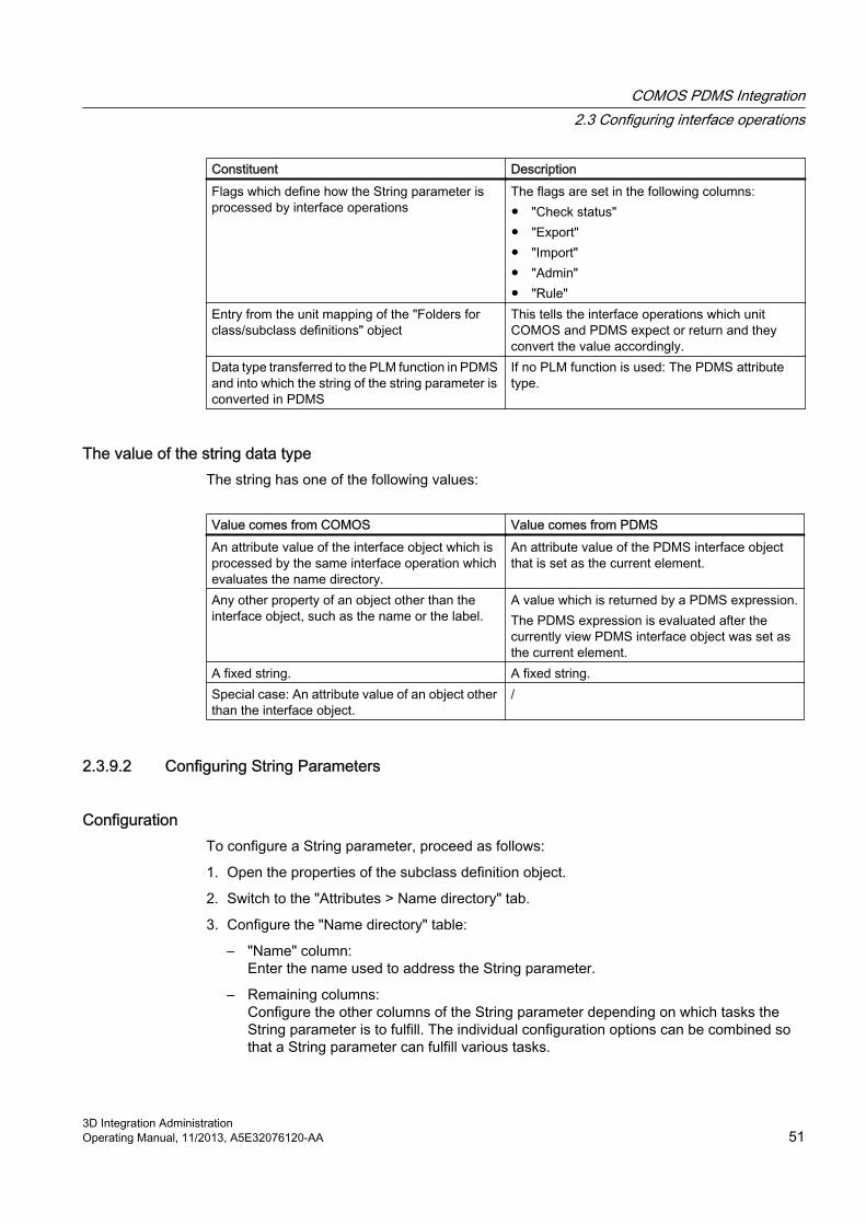
Constituent DescriptionFlags which define how the String parameter is processed by interface operations
The flags are set in the following columns:● "Check status"● "Export"● "Import"● "Admin"● "Rule"
Entry from the unit mapping of the "Folders for class/subclass definitions" object
This tells the interface operations which unit COMOS and PDMS expect or return and they convert the value accordingly.
Data type transferred to the PLM function in PDMS and into which the string of the string parameter is converted in PDMS
If no PLM function is used: The PDMS attribute type.
The value of the string data typeThe string has one of the following values:
Value comes from COMOS Value comes from PDMSAn attribute value of the interface object which is processed by the same interface operation which evaluates the name directory.
An attribute value of the PDMS interface object that is set as the current element.
Any other property of an object other than the interface object, such as the name or the label.
A value which is returned by a PDMS expression.The PDMS expression is evaluated after the currently view PDMS interface object was set as the current element.
A fixed string. A fixed string.Special case: An attribute value of an object other than the interface object.
/
2.3.9.2 Configuring String Parameters
Configuration To configure a String parameter, proceed as follows:
1. Open the properties of the subclass definition object.
2. Switch to the "Attributes > Name directory" tab.
3. Configure the "Name directory" table:
– "Name" column:Enter the name used to address the String parameter.
– Remaining columns:Configure the other columns of the String parameter depending on which tasks the String parameter is to fulfill. The individual configuration options can be combined so that a String parameter can fulfill various tasks.
COMOS PDMS Integration2.3 Configuring interface operations
3D Integration AdministrationOperating Manual, 11/2013, A5E32076120-AA 51

TasksA String parameter can fulfill the following tasks:
1. It assigns a COMOS value to a variable.*
2. It assigns a PDMS value to a variable.*
3. It writes a PDMS value to a COMOS attribute (import).
4. It writes a COMOS value to a PDMS object (export).
5. It generates a component of a mapping entry in name mapping (variables definition).
6. An interface operation compares the value of a COMOS interface object returned by the String parameter with the value of the connected PDMS object returned by the String parameter (check).
7. The "Export" interface operation uses the String parameters to check whether it is permissible to create an object under a specific owner.
The tasks marked with "*" provide the basis for the remaining tasks.
Assign a COMOS value to a variable (task 1)● Configure the "Comos attribute" column.
Information regarding configuration: See the end of the chapter.
● "PDMS type" column: Select any data type. The software expects a value.
Assign a PDMS value to a variable (task 2)● Configure the "PDMS attribute/expression" or "GetFunction" column.
Information regarding configuration: See the end of the chapter.
● "PDMS type" column: Select any data type. The software expects a value.
Import (task 3)Configure the following columns so that the String parameter writes a PDMS value to a COMOS attribute:
● "Comos attribute" column:Only attribute name permitted. Information regarding configuration: See the end of the chapter.
● "PDMS attribute/expression" or "GetFunction" column:Information regarding configuration: See the end of the chapter.
● "Unit" column:You are offered the entries from the unit mapping in the "Folders for class/subclass definitions" folder. Choose a suitable entry.
● "PDMS type" column:Specify the data type that is to be transferred to the PML function.
● "Import" column: Select "Yes".
COMOS PDMS Integration2.3 Configuring interface operations
3D Integration Administration52 Operating Manual, 11/2013, A5E32076120-AA

Export (task 4)To enable the String parameter to write a COMOS value to a PDMS attribute, proceed as follows:
● "Comos attribute" column:Information regarding configuration: See the end of the chapter.
● "SetFunction" or "PDMS attribute/expression" column:Information regarding configuration: See the end of the chapter.If both columns were configured, SetFunction has a higher priority.
● "Unit" column:You are offered the entries from the unit mapping in the "Folders for class/subclass definitions" folder. Choose a suitable entry.
● "PDMS type" column:Specify the data type that is to be transferred to the PML function.
● "Export" column:Select "Yes".
Generate the name mapping part (task 5)Proceed as described below so that the String parameter generates one of the following components of a mapping entry in name mapping.
● "Data item"
● "Prefix"
● "Postfix"
● "Fixed name"
Configure the following columns of the String parameter:
● "Admin" column:Select "Yes".
● "Comos attribute" or "PDMS attribute/expression" or "GetFunction" column:Define which string the String parameter returns. If more than one column is set, following priority applies: "Comos attribute" > "GetFunction" > "PDMS attribute/expression"Information regarding configuration: See the end of the chapter.
● "PDMS type" column:Select any data type. The software expects a value.
COMOS PDMS Integration2.3 Configuring interface operations
3D Integration AdministrationOperating Manual, 11/2013, A5E32076120-AA 53

Check (task 6)Configure the following columns so that an interface operation compares the values of a COMOS object returned by the string parameter with those of the PDMS object to which it is connected:
● "Check" column:Select "Yes".
● "Comos attribute" and "PDMS attribute/expression" or "GetFunction" column:Access a COMOS value and a PDMS value.Information regarding configuration: See the end of the chapter.
● "PDMS type" column: Select any data type. The software expects a value.
Check owner (task 7)Configure the following columns so that the "Export" interface operation uses the string parameters to check whether it is permissible to create an object under a specific owner:
● "Rule" column:Select "Yes".
● "Comos attribute" and "PDMS attribute/expression" or "GetFunction" column:Access a COMOS value and a PDMS value.The PDMS expression GetFunction is called at the potential owner of the object that is to be created in PDMS.Information regarding configuration: See the end of the chapter.
● "PDMS type" column: Select any data type. The software expects a value.
● The object is only created if the values are the same.
MiscellaneousPlease note the following points:
● If the "Export" and "Import" columns are activated, the "Export" column takes higher priority. The "Import" column is not evaluated.
● "PDMS type" column: Always mandatory, even if no value is transferred to a PML function.
● "SetFunction" and "PDMS attribute/expression" columns are set:SetFunction has higher priority.
● "GetFunction" and "PDMS attribute/expression" columns are set:GetFunction has higher priority.
See alsoConfiguring the "Comos attribute", "PDMS attribute/expression", "GetFunction", and "SetFunction" columns (Page 55)
COMOS PDMS Integration2.3 Configuring interface operations
3D Integration Administration54 Operating Manual, 11/2013, A5E32076120-AA

2.3.9.3 Configuring the "Comos attribute", "PDMS attribute/expression", "GetFunction", and "SetFunction" columns
Which of these columns you configure and which entries are permitted depends on the purpose for which you are using the String Parameter.
ProcedureStep 1: Define which task the String Parameter fulfills. This derives the action it executes.
Purpose ActionVariable definition
The value is fetched from PDMS or COMOS.
Export The value is fetched from COMOS and written to PDMS.Import The value is fetched from PDMS and written to COMOS.Check A value is fetched from COMOS and PDMS in order to compare the two values with
each other.
Step 2: The actions determine which columns you configure:
Action Column Permissible entriesFetch value from COMOS
Column: "Comos attribute": ● Attribute name● Fixed string● Call of an owner method
Set value in COMOS
Column: "Comos attribute": ● Attribute name
Fetch value from PDMS
"PDMS attribute/expression" column:or
● Attribute name● Expression● Fixed string
"GetFunction" column: ● Name of a GetFunctionSet value in PDMS
Column: "PDMS attribute/expression":or
● Attribute name
"SetFunction" column: ● Name of a SetFunction
COMOS PDMS Integration2.3 Configuring interface operations
3D Integration AdministrationOperating Manual, 11/2013, A5E32076120-AA 55

NotationUse the following notation:
Column Notation"Comos attribute"
● Attribute name:Use the NestedName: "<Tab name>.<Attribute name>"The String Parameter returns the DisplayValue of the attribute.
● Fixed string:Set the fixed string inside double quotation marks.
● Call of an owner method:Enter a command in the field which returns the required value. Use the key word Owner. The same functions and properties are available as in the COMOS Object Debugger.Example: The String Parameter should return the label of the owner of the currently processed interface object: "Owner.Label"
"PDMS attribute/expression"
● Attribute name:Enter the name of the PDMS attribute.
● Expression:Enter the PDMS expression.
● Fixed string:Set the fixed string inside single quotation marks.
"GetFunction" Enter the name of the GetFunction which is to be executed in PDMS. The GetFunction returns a PDMS value.Example: "!!GetPurpose()"
"SetFunction" Enter the name of the SetFunction which is to be executed in PDMS. The SetFunction writes a value to PDMS.Example: "!!SetPurpose()"
See alsoConfiguring String Parameters (Page 51)
COMOS PDMS Integration2.3 Configuring interface operations
3D Integration Administration56 Operating Manual, 11/2013, A5E32076120-AA

2.3.10 Configuring site mapping and location mapping in name mapping
2.3.10.1 Structure of the tables for unit and location mappingYou will find the tables for site mapping and location mapping at the subclass definition objects of the "Cable" and "Tagged item" classes on the "Name mapping" tab.
● The tables for site mapping and location mapping have the same structure.
● Each column in the table defines a mapping entry.
● Each mapping entry contains the rows listed in the table below. These rows save all information that is required to execute one of the following actions:
– Generate the name of the PDMS object to which a COMOS interface object is connected
– Derive the path to the COMOS interface object to which the object is connected from the name of a PDMS object.
– Create the COMOS interface object at the position in the tree structure stipulated by the PDMS name.
– Complete the owner structure of the COMOS interface object identified by the PDMS name.
– Assign a reference from a COMOS interface object to another COMOS object.
Row name Function Comment"Prefix" The prefix of a PDMS name part. Used to generate/break down the PDMS
name part of the mapping entry."Suffix" The suffix of a PDMS name part."Data item" The data item of a PDMS name
part."Start index" The point where a PDMS name
part is inserted in the full PDMS name.
"Number of characters"
The length of a PDMS data item.
"Fixed name" The name of a COMOS object, used to structure the COMOS data
Only used to generate a path to a COMOS object
"Base object" Base object used to create an object.
Only used to complete the owner structure of the COMOS interface object or to create the interface object in COMOS."Base object from
structure"Flag whether the engineering structure linked to the project is used to create an object.
2.3.10.2 Algorithm for generating a PDMS name
IntroductionA PDMS name comprises a number of name parts. Each mapping entry in name mapping returns a name part. When put together, the mapping entries produce a full PDMS name.
COMOS PDMS Integration2.3 Configuring interface operations
3D Integration AdministrationOperating Manual, 11/2013, A5E32076120-AA 57

Elements of a PDMS name part The PDMS name part of a mapping entry is defined by the following elements:
● Optionally: A prefix
● A data item
● A position within the full name
● A length
● Optionally: A postfix
Content of the data itemThe data item of a mapping entry contains either COMOS data or PDMS data. The following data is permitted:
COMOS data PDMS data● Return value of a String Parameter which
returns COMOS data.Return value of a String Parameter which returns PDMS data.
● An expression which returns the name or label of an object in the unit tree.
/
● An expression which returns the name or label of an object in the location tree.
/
AlgorithmTo generate the name of the PDMS object to which a COMOS interface object is to be connected, the interface proceeds as follows:
1. It checks which subclass the COMOS object has and evaluates the creation mode of the subclass definition object:
– "Create in unit tree": Unit mapping is performed.
– "Create in location tree": Location mapping is performed.
2. The mapping entries are evaluated. The evaluation is performed from left to right. The following algorithm is executed for each mapping entry:
– The data item is evaluated.
– If no data entry was defined, the name part of this mapping entry is not processed. The algorithm continues with the next mapping entry.
– If the data item is longer than is permitted by the "Number of characters" cell, it is truncated.
– Prefix (if necessary truncated), data item and postfix are combined to form a character string - the PDMS name part.
3. The PDMS name parts are combined to form a string which cannot be modified. Each name part is copied to the position in the string defined by its start index.
4. If the index ranges of two name parts overlap, the name part of the later evaluated mapping overwrites the first evaluated mapping.
COMOS PDMS Integration2.3 Configuring interface operations
3D Integration Administration58 Operating Manual, 11/2013, A5E32076120-AA
2.3.10.3 Algorithm for generating a COMOS path name
IntroductionTo find the COMOS object to which a PDMS object is to be connected, the interface breaks down the name of the PDMS object into its name parts. The interface then derives the path to the correct node in the tree structure from the name parts.
AlgorithmThe interface proceeds as follows:
1. It checks the which subclass the PDMS interface object has. To do this, it evaluates the following UDA: ":ComosSClass"
2. It evaluates the creation mode of the corresponding subclass definition object: "General" tab, "Structural behavior" control group, "Creation mode" list:
– "Create in unit tree": Unit mapping is performed.
– "Create in location tree": Location mapping is performed.
The execution of the mapping tables involves the following steps:
1. Starting with the last PDMS name part, the interface extracts the PDMS name parts from the PDMS name. To do this, it evaluates the start index and the number of characters of the corresponding mapping entry.For the last name part, the mapping entry on the far right is used; for the penultimate name part, the second mapping entry from the right is used, and so on.
2. The interface processes the individual mapping entries starting with the mapping entry on the far right.
The following algorithm is executed for each mapping entry:
1. The entry in the "Data item" row is checked:
– Name of a String Parameter:Consequence: A corresponding COMOS node does not exist for the name part. Continue with step 2.
– Name or label of a COMOS object:If there is one: The prefix and postfix are removed from the PDMS name part.The remainder of the string represents the name or the label of a COMOS object. It is copied to the path list.
– Nothing entered: Continue with step 2.
2. If the "Data item" row is empty or contains a String Parameter, a check is made whether the "Fixed name" row has been configured:
– "Fixed name" not set: The processing of the mapping table is aborted for the object.
– "Fixed name" set: The entered or resulting string is written to the path list.
Once all mapping entries have been processed, the sequence of the entries in the path list is reversed.
COMOS PDMS Integration2.3 Configuring interface operations
3D Integration AdministrationOperating Manual, 11/2013, A5E32076120-AA 59

Result● The string written to the path list produces the path to the COMOS interface object you are
looking for.
● If the object does not exist yet, the mapping table returns all needed information in order to create it. The name part of the last mapping entry is written to the "Name" property of the COMOS object.
● If the interface detects that the owner structure of the object you are looking for is incomplete: The mapping table returns all information required to complete the owner structure.
2.3.10.4 Algorithm for generating a COMOS object through name mapping
AlgorithmTo create an interface object in COMOS and, if necessary, to complete its owner structure, the interface has to know which base objects are used.
To create the owner structure, COMOS evaluates the "Base object" or "Base object from structure" row of the name mapping.
To create the interface object which is actually searched for, the interface starts by evaluating the UDS ":ComosBaseOb" of the PDMS interface object. If the UDA is empty, it evaluates the "Base object" or "Base object from structure" row in the name mapping. If no entry has been made here, the interface evaluates the "General" tab of the subclass definition object.
This documentation assumes that this setting is made via the "General" tab.
If you define the base object via name mapping, the algorithm described below is used.
Evaluation of the "Base object" rowThe here specified base object is used.
Evaluation of the "Base object from structure" rowOnly activate the "Base object from structure" setting if the project is linked to a project structure.
If the setting is activated, the interface proceeds as follows:
● It navigates to the project structure level corresponding to the current mapping entry.
● In a project structure, several objects with different base objects can be prepared for a single level. The interface compares the data item or fixed name of the current mapping entry with the name mask of the possible base objects.
● The object is created with the base object whose name mask matches the data item or fixed name of the mapping entry.
● The data item or fixed name is entered in the "Name" property of the new object.
COMOS PDMS Integration2.3 Configuring interface operations
3D Integration Administration60 Operating Manual, 11/2013, A5E32076120-AA

See alsoDefining the base object for the creation of interface objects (Page 46)
2.3.10.5 Configuring unit mapping and location mapping
RequirementYou have defined the structural behavior.
Structural behavior determines configurationThe structural behavior of the subclass determines which of the mapping tables you can configure on the "Name mapping" tab:
Creation mode Assignment mode Mapping"Create in unit tree" "Assign to location in location
tree"Site mapping and location mapping
"Create in unit tree" "None" Site mapping"Create in location tree" "Assign to location in unit
tree"Site mapping and location mapping
"Create in location tree" "None" Location mapping
Procedure1. Open the properties of the subclass definition object of the "Cable" or "Tagged item" class.
2. Select the "Attributes > Name mapping" tab.
3. Configure the "Site mapping" and "Location mapping" tables as described below.
4. Identify where objects of the subclass are located or need to be created in your COMOS object structure. Split the overall path into its individual nodes.
5. Analyze how the PDMS name for objects of the subclass is structured and split it into its name parts.A PDMS name part consists of the following constituent parts:
– (Optional) prefix
– Data item
– (Optional) postfix
6. Analyze which COMOS nodes and PDMS name parts can be mapped directly to one another.Configure a shared mapping entry for these nodes and name parts. Information regarding configuration: See the table below.
COMOS PDMS Integration2.3 Configuring interface operations
3D Integration AdministrationOperating Manual, 11/2013, A5E32076120-AA 61

7. Analyze which COMOS nodes do not have a corresponding PDMS name part and vice versa.Configure a separate mapping entry for each of these nodes and name parts. Information regarding configuration: See the table below.Examples of COMOS nodes which do not have a corresponding PDMS name part:
– Folder
– The PDMS root object on the "Locations" tab
– Other objects that are only used to structure the COMOS data
8. Configure the mapping entries as described in the table below.The sequence of the mapping entries is the same as the sequence of the COMOS nodes from the overall path, although if necessary it may be interrupted by mapping entries for PDMS name parts for which there are no nodes.This makes it possible to generate a PDMS-compatible names from the object path which is unique throughout PDMS.Information regarding notation: See below.
Row COMOS node without a corresponding PDMS name part
COMOS node with a corresponding PDMS name part
PDMS name part without a corresponding COMOS node
"Prefix" / Optionally"Suffix" / Optionally"Data element" / ● Mandatory
● Only an expression which returns the name or label of an object from the unit tree or location tree is permitted
● Mandatory● Only String parameter
is permitted
"Start index" / ● Mandatory"Number of characters"
/ ● Mandatory
"Base object" ● Mandatory● Only one of the two● See below
● Mandatory● Only one of the two● See below
/"Base object from structure"
/
"Fixed name" ● Mandatory● String parameter
which evaluates COMOS data or
● Fixed string
/
COMOS PDMS Integration2.3 Configuring interface operations
3D Integration Administration62 Operating Manual, 11/2013, A5E32076120-AA

"Base object" and "Base object from structure" rows● Mapping entry on the far right:
In this field you can specify which base object uses the interface object you are actually looking for.This documentation assumes that the base object is defined via the "General" tab of the subclass definition object, in the "Base objects for creating objects" control group.
● Remaining mapping entries:Define which base objects are used by the individual levels of the owner structure.
NotationUse the following notation:
● "Prefix" row: Any number of characters
● "Postfix" row: Any number of characters
● "Data item" row:A String parameter or an expression composed of a number of elements:
String parameter notation Notation of the composed expression"!<Name of a local String parameter>" example: "!Area"
First element:● In site mapping: "U"● In location mapping: "L"
"!!<Name of a global String parameter>"
Second element● "<Number>": Structure level in the tree on which the object is located
In site mapping: Starting from the project rootIn location mapping: Starting from the object "Folders for class/subclass definitions (PDMS)"
Third element:● "N" or "L": Use the name or label of the objectExample: "U2L": Use the label of an object on the second level underneath the project root in the unit tree
● "Start index" row:The start indexIf nothing is entered, the name part is appended to the up to this point composed name parts.
● "Number of characters" row:
– Number
– Any number of characters permitted
● "Base object" row:
– SystemFullName of the base object
– Use "\" to separate the individual nodes.
COMOS PDMS Integration2.3 Configuring interface operations
3D Integration AdministrationOperating Manual, 11/2013, A5E32076120-AA 63

● "Base object from structure" row: Flag
– "Yes": If the project is linked to a project structure, the project structure is used for the generation of the COMOS objects.
– "No": Even if a project structure is available and linked, it is not used.
● "Fixed name" row:One of the following values:
– Local String parameter: "!<Name of a local String parameter>"
– Global String parameter: "!!<Name of a global String parameter>"
– Fixed string: Without quotation marks
2.3.10.6 Configuring level rules
ProcedureTo define a deviation from the standard evaluation of site mapping and location mapping, proceed as follows:
1. Open the properties of the subclass definition object.
2. Activate the "Attributes > Name mapping" tab.
3. Right-click a field in the right-hand column of the "Level rules" table.Result: The field is activated and highlighted in color.
4. Right-click the field a second time with the mouse.Result: A list is displayed in the field.
5. To activate the rule, select "Yes".To deactivate the rule, select "No".
See alsoLevel rules of name mapping (Page 24)
2.3.11 Configuring COMOS queries from PDMS
2.3.11.1 WorkflowUsers who wish to execute and view COMOS queries in PDMS first have to complete the following preparatory steps:
● Create however many COMOS queries the user is to execute in PDMS.These queries are called main queries in the interface.
● Configure the main queries in the usual COMOS way.
● Create a class definition object for the "Query" class.
● For each main query: Create a subclass definition object.
COMOS PDMS Integration2.3 Configuring interface operations
3D Integration Administration64 Operating Manual, 11/2013, A5E32076120-AA

● Configure the subclass definition objects.
● If the user should have the option to select the start object of a main query from a list of objects in PDMS:
– Create a COMOS query whose result list returns the possible start objectsThis query is called the start object query in the interface.
– Configure the start object query.
– Configure the access to the start object query for the subclass definition object.
2.3.11.2 Creating and configuring COMOS queries
Procedure● For each query that is started from and viewed in PDMS, create a main query and configure
it in the usual COMOS way.If you are using an already existing query as the main query, this step is not necessary.
● If the user should have the option to select the start object of a main query from a list of objects in PDMS:Create a start object query and configure it in such a way that it returns useful start objects for the main query.If you are using an already existing query as the start object query, this step is not necessary.
2.3.11.3 Creating definition objects for queries
Creating the class definition objectTo create the class definition object for queries, proceed as follows:
1. Click the "Units" tab in the Navigator.
2. Select the "Folders for class/subclass definitions" object.
3. Select the "New > Query class definition" command in the context menu.
Creating the subclass definition objectTo create a subclass definition object you use to manage a main query and its start object query, proceed as follows:
1. Select the "Query class definition" class definition object in the Navigator.
2. Select the "New > Query subclass definition" command in the context menu.A subclass definition object is created.
COMOS PDMS Integration2.3 Configuring interface operations
3D Integration AdministrationOperating Manual, 11/2013, A5E32076120-AA 65

3. Open the properties of the subclass definition object.
4. "PDMS settings" control group:
– "Name" field:Enter a name. The name is offered to the user for selection in PDMS: "Query Comos" window, "Query" tab, "Query" list
– "Description" field:Enter a description. If the user has selected the query in PDMS, the description is displayed there: "Query Comos" window, "Query" tab, "Description" field
2.3.11.4 Configuring a subclass definition object for queries
ProcedureTo configure the subclass definition object you use to manage the main query and the start object query, proceed as follows:
1. Open the properties of the subclass definition object.See also chapter Creating definition objects for queries (Page 65).
2. Switch to the "Attributes > General" tab.
3. "Output format" control group:
– In the "Output format" list, select the format in which the result list of the query will be transferred to PDMS. Possible output formats: CSV and XML.
– If CSV is set as the output format, define the column separator in the "Separator" field. The separator character is arbitrary.
COMOS PDMS Integration2.3 Configuring interface operations
3D Integration Administration66 Operating Manual, 11/2013, A5E32076120-AA

4. "Main query" control group:
– Drag&drop the main query from the Navigator into the "Query object" field.
– Drag&drop an object into the "Start object" field.The name of the here referenced start object is displayed to the user in PDMS: "Comos Query" window, "Query" tab, "Start object" fieldIf you are using an already existing query as the main query: You can define a start object other than the one set in the main query.
– Drag&drop the base objects according to which the query is to filter the result list from the Navigator to the "Base objects" column.If you are using an already existing query as the main query: You can filter the query in PDMS on the basis of base objects other than those defined by the main query in COMOS.
5. "Query for start objects" control group:Only configure this group if the user should to be able to select the start object of a main query from a list of objects in PDMS:
– Drag&drop the query for start objects from the Navigator into the "Query object" field.The start object query returns the list of possible start objects in PDMS.
– Drag&drop an object into the "Start object" field.
– Drag&drop the base objects according to which the query is to filter the result list from the Navigator to the "Base objects" column.If you are using an already existing query as the start object query: You can filter the query in PDMS on the basis of base objects other than those defined by the main query in COMOS.
Evaluation priority for the start object You can define the start object of the query in various places. The following table lists these places.
If a start object has been defined in multiple places, the places which appear further down the table overwrite those above them.
Start object of the main query Start object of the query for start objectsThe start object which is set in the COMOS query The start object which is set in the COMOS queryThe start object which was set at the subclass definition object
The start object which was set at the subclass definition object
The start object which the user defined in PDMS: "Comos Query" window, "Execute" tab
/
See alsoThe "General" tab (Page 103)
COMOS PDMS Integration2.3 Configuring interface operations
3D Integration AdministrationOperating Manual, 11/2013, A5E32076120-AA 67

2.3.12 Configuring "Import DocLinks"
2.3.12.1 Defining the entry for the target document in PDMS
IntroductionTo import draft objects into COMOS as DocObjs, the interface has to know the COMOS document for which the DocObjs are being created.
For this purpose, you should define an attribute or a UDA in which the user will subsequently enter the name or the SystemUID of the target document.
You decide on which level or levels of the draft structure target documents may be specified.
Defining target documents on different levels of the draft structureYou can specify a target document on more than one level of the draft structure. This enables the user to start the DocLink import as required on different levels of the draft structure, e.g. for all draft objects in a region, for an individual view, or for an individual drawing.
To do this, repeat the below described procedure for all levels for which the "Import DocLinks" operation needs to be available.
ProcedureTo define where the target document is specified, proceed as follows:
1. Define whether the user enters the name of the target document in an attribute or in a UDA and which attribute or UDA is used.
2. Define the level of the draft structure on which the user specifies the name of the target document.
3. If you choose to use a UDA: Create the UDA.
2.3.12.2 Configuring "Import DocLinks" in COMOS
ProcedureTo configure the "Import DocLinks" operation in COMOS, proceed as follows:
1. Create a "Document subclass definition" object.
2. In the subclass definition object name directory, define a String parameter which addresses the attribute or UDA in which the name or SystemUID of the target document is entered. See also chapter Defining the String Parameter for the document name (Page 69).
3. Configure the general properties of the subclass definition object. See also chapter Configuring general settings (Page 69).
4. Optionally: On the "Restrictions for owners" tab, specify whether the owners of the template objects for which DocObjs are being generated have to meet certain conditions.
COMOS PDMS Integration2.3 Configuring interface operations
3D Integration Administration68 Operating Manual, 11/2013, A5E32076120-AA

2.3.12.3 Defining the String Parameter for the document nameDefine a String parameter which, from PDMS, reads out the name of the COMOS document under which the DocObjs are imported.
Procedure1. Open the properties of the "Document subclass definition" object and switch to the "Name
directory" tab.
2. Configure the "Name directory" table:
– "Name" column: Enter the name of the String parameter.
– "PDMS attribute/expression" or "GetFunction" column: Access the value of the attribute or the UDA in which the document name or the SystemUID is saved in PDMS. See also chapter Working with String Parameters in the name directory (Page 50).
– "PDMS type" column: Enter "String".
2.3.12.4 Configuring general settings
ProcedureTo define the general settings of the "Document subclass definition" object, proceed as follows:
1. Open the properties of the "Document subclass definition" object.
2. Switch to the "Attributes > General" tab.
3. "Document ID" field:
– Enter the name of the String parameter which reads out the document name from PDMS.
– Do not precede the name of the String parameter with a "!" character.
4. Optionally: Define filters in the "Base object for document search" control group:Result: During the search, the interface restricts itself to documents which meet the criteria defined here. This speeds up the search.The following filters are possible:
– "Document type" list: Select the document type of the document.
– "Base object for document search" field: Select the base object the document uses.
– "Base object" field: Select the node under which the document is searched.
5. Optionally: Activate the "Filter unnamed objects" option:In PDMS, only objects with a name are displayed in the result list in the "Export to Comos" window.
6. Enter the PDMS element types of the following template objects in the table: Template objects with a DDNM attribute which references a design object connected to a COMOS object.
COMOS PDMS Integration2.3 Configuring interface operations
3D Integration AdministrationOperating Manual, 11/2013, A5E32076120-AA 69

2.3.12.5 Defining restrictions for owners for draft objects
ProcedureYou can define owner restrictions which the template objects have to meet to be imported as DocObjs.
To do this, proceed in the same way as for the definition of owner restrictions on subclass definition objects of the "Cable" and "Tagged item" classes. See also chapter Restrictions for owners (Page 47).
2.3.13 Synchronizing settings
Initial situationTo ensure that COMOS and PDMS use the same settings, the interface does not directly access the settings for the "Folders for class/subclass definitions" object and for the class and subclass definition objects. Instead, the settings are written to an XML file in the exchange directory. COMOS and PDMS load the settings from the file to the working memory of your computer.
When an interface operation is called, the current version number of the "Folders for class/subclass definitions" object is transferred. The operation checks whether the number is identical to the version number of the settings stored in the working memory.
● Yes: The settings stored in the working memory are used.
● No: The file is loaded to the working memory again. The settings are synchronized.
Synchronization successfulMake sure that the current settings in the file in the exchange directory are up to date.
Update the file whenever you have performed one of the following actions:
● You changed the settings of the "Folders for class/subclass definitions" object.
● You created a new class or subclass definition object.
● You changed the settings of a subclass definition object.
ProcedureTo update the file in which the settings for the "Folders for class/subclass definitions" object and the class and subclass definition objects are saved, proceed as follows:
1. Select the "Folders for class/subclass definitions" object in the Navigator.
2. Select the following command from the context menu: "PDMS > Save subclasses".
COMOS PDMS Integration2.3 Configuring interface operations
3D Integration Administration70 Operating Manual, 11/2013, A5E32076120-AA

Result● The version number at the "Folders for class/subclass definitions" object is incremented.
● The standard table for subclasses is updated.
● The settings for the "Folders for class/subclass definitions" object and for the class and subclass definition objects are written to the file in the exchange directory.
2.3.14 Importing AVEVA design templates
Initial situationYou can assign an AVEVA design template to an interface object as a model.
To do this, you need to import the design templates from PDMS into COMOS.
ProcedureTo import the AVEVA design templates from PDMS into COMOS, proceed as follows:
1. Switch to the "Base objects" tab in the Navigator.
2. Select the following node "@20 > D30 > A30 > Y00R00038 Objects for design template structure".
3. In the context menu, select the following command: "PDMS > Update design templates".
Result● The GTypes of all templates are evaluated in PDMS.
● The templates are imported from PDMS to COMOS. During this process, the interface proceeds as described below.
Managing the design templates in the base dataThe design templates are managed under the following node in the base data:
"@20 > D30 > A30 > Y00R00038 Objects for design template structure"
The design templates are managed sorted by GType:
● Nodes which represent the GTypes of the templates are located on the first level below the "Objects for design template structure" object.
● The nodes for the templates are located on the second level. A node is created for each template.
COMOS PDMS Integration2.3 Configuring interface operations
3D Integration AdministrationOperating Manual, 11/2013, A5E32076120-AA 71

Algorithm for importing the design templates into the base data● For each GType found in PDMS, a search is performed below the "Objects for design
template structure" object for a node whose name matches the name of the GType.
● If a node of this type does not exist yet, it is created. The name of the GType is entered in the "Name" property of the node.
● A node for the design template is created underneath the GType node.
● If the design template already exists, it is updated. No data is deleted during the update operation.Example:
– A sub template was deleted in PDMS.
– The sub template remains available in COMOS even after the update.
● The attributes of the template node are automatically set when the template node is created or during the update.
2.3.15 Configuring COMOS interface objects
2.3.15.1 Assigning the class, subclass, and PDMS element type
ProcedureTo assign a class, a subclass, and PDMS element types to an interface object, proceed as follows:
1. Click on the "Base objects" tab in the Navigator.
2. Navigate to an interface base object.
3. Open the properties of the interface base object.
4. Switch to the "Attributes > External 3D Interface" tab.
5. Configure the tab as described below.
6. "Class" list:
– Select a class.
– Do not select the "Undef" value. Otherwise, the object will not be recognized as an interface object.
7. "Subclass" list:Select a subclass. Only subclasses permitted for the selected class are offered.
8. "PDMS element type" list:Select a PDMS element type. Only those element types entered for the selected subclass are offered.
COMOS PDMS Integration2.3 Configuring interface operations
3D Integration Administration72 Operating Manual, 11/2013, A5E32076120-AA

Overwriting the preselection in the engineering viewIn the database, the edit mode of these attributes is configured in such a way that users can overwrite the inherited settings in the engineering view, if this is necessary.
See alsoAttributes of the "External 3D Interface" tab (Page 105)
2.3.15.2 Overwriting the inherited model information
Requirements● A class, a subclass, and a PDMS element type have already been assigned to the interface
object.
● AVEVA templates have been imported.
Inheritance from subclassThe database is configured in such a way that the interface objects take the model information settings from their subclass. For this purpose, the model attributes of the interface objects are linked to those of the subclass definition objects.
Link type: Static link via the "GetLinkedSpecification" script function.
The database is configured in such a way that you can overwrite the settings taken from the subclass at the base objects of the interface objects.
ProcedureTo define the model information at the base object of the interface object, proceed as follows:
1. Click on the "Base objects" tab in the Navigator.
2. Navigate to an interface base object.
3. Open the properties of the interface base object and switch to the "Attributes > External 3D Interface" tab.
4. Configure the "Model" control group as described in the following.
COMOS PDMS Integration2.3 Configuring interface operations
3D Integration AdministrationOperating Manual, 11/2013, A5E32076120-AA 73

5. "Mode" list:Define how the model is generated. Select one of the following modes:
Mode Interface object has subclass of "Cable" class
Interface object has subclass of "Tagged item" class
Result
"Design template"
/ Available if the subclass has the "EQUI" PDMS element type
The geometry is based on a design template.
"PDMS element"
/ Available The geometry is copied from an existing PDMS element.
"Function" Available Available The geometry is generated by a function which is also performs other initializations.
"None" Available Available A box is generated.
6. Depending on which mode you have selected, you now need to define the details for the generation of the model:
– "Function" mode:Enter the function call in the "Function" field.
– "PDMS element" mode:Enter the name of the PDMS element whose geometry is being copied in the "Element" field.
– "Design template" mode:Define the main template in the "Design template" control group, along with the used sub templates which, if applicable. Further information: See below.
Defining design templates If the following conditions are met, you can select design templates as the basis for your model:
● The subclass of the interface object has the "Tagged item" class.
● The subclass has the "EQUI" PDMS element type.
If you select a design template as the basis for your model, you need to configure the "Design template" control group.
Proceed as follows:
1. "Main document template" list:
– Select the main document template.
– Only those templates whose GType has been entered in the subclass in the "GTypes for filtering" field are offered for selection.
– If the the "EQUI" PDMS element type is missing at the subclass, the list remains empty.
2. "Sub template 1" to "Sub template 5" lists:
– You can define up to five templates for secondary equipment.
– Which templates are offered depends on the main template you selected.
COMOS PDMS Integration2.3 Configuring interface operations
3D Integration Administration74 Operating Manual, 11/2013, A5E32076120-AA

Design templates in the engineering viewWhen COMOS creates an interface object in the engineering view, it automatically checks whether the interface object uses a design template. If it does, COMOS creates the main document template underneath the interface object and the sub templates underneath that.
COMOS also creates the template objects when you assign a design template to an existing interface object.
● Name of the template object: "Y00R00038 Objects for design template structure"
● Description of the template object: As defined at the base object of the template object
You can change the design parameters of the template objects in the engineering view: Properties of the template object, "Attributes > External 3D Interface" tab, attributes "Y00A02118AA01 DP 01" through "Y00A02118AA10 DP 10".
Overwriting the base object settings in the engineering viewUsers can overwrite both the settings inherited from the subclass and the settings predefined at the base object in the engineering view.
Restoring the default settingsThe settings inherited from the subclass can be restored in the engineering view using the "Refresh static links on tab" context menu.
See alsoAttributes of the "External 3D Interface" tab (Page 105)
2.4 Communication process
2.4.1 Communication modes
Directed communication processHow COMOS and PDMS communicate with one another depends on the application in which the communication process starts:
● From PDMS to COMOS
● From COMOS to PDMS
COMOS PDMS Integration2.4 Communication process
3D Integration AdministrationOperating Manual, 11/2013, A5E32076120-AA 75

Direct communication and file pipe communicationIf communication starts in COMOS, the communication process is also determined by the installation modes of PDMS and COMOS.
● Direct communication: Both applications run locally on the same workstation.
● File pipe communication: COMOS runs on a Citrix server.
2.4.2 COMOS to PDMS
General rulesCOMOS uses commands to communicate with PDMS. These commands are sent to the PDMS command line via the Windows Messaging Service.
All commands which go from COMOS to PDMS call a function in PDMS. They generate no PML command that are directly send to PDMS.
This procedure has the advantage that COMOS does not work with PML. Changes to PML by AVEVA do not affect the COMOS side of the interface.
COMOS PDMS Integration2.4 Communication process
3D Integration Administration76 Operating Manual, 11/2013, A5E32076120-AA

ProcessThe following diagram provides you with an overview of how the communication process works when it starts in COMOS. The diagram maps the process for direct communication and file pipe communication:
Setup detailsThe following requirements apply for direct communication and file pipe communication:
● The "talkcmd" window is active in PDMS.
● In the wait state, the window is called "Comos Command Interface".
The following requirements also apply for file pipe communication:
COMOS PDMS Integration2.4 Communication process
3D Integration AdministrationOperating Manual, 11/2013, A5E32076120-AA 77

● The same value has been entered in the "PDMSCmdFile" system environment variable on the client and the server.The variable contains the path name and the name of the file COMOS and PDMS use for communication, and which is monitored by the COMOS Server Command Service and the Client Command Service.Example:
– Server: "\\client\c$\filename"
– Clients: "c:\filename"
● The Client Command Service is running on the client.Name: "PDMSToCitrix.exe"Name of window: "Comos Command Service"
● In PDMS:The PDMS environment variable "COMOSEXCHANGEPATH" has been created. The variable specifies the default path to the exchange file. The same value was entered in the variable as in the following COMOS project property:Project properties, "PDMS" category, "Exchange directory" field.
2.4.3 PDMS to COMOS
ProcessIf communication starts in PDMS, the interface does distinguish between direct communication and file pipe communication.
The following diagram provides you with an overview of the communication process if it starts in PDMS:
COMOS PDMS Integration2.4 Communication process
3D Integration Administration78 Operating Manual, 11/2013, A5E32076120-AA

● When an interface operation is called in PDMS, the ITCommander creates an XML file and stores it in the exchange path.
● It also creates a communication file and saves it in the communication path. The communication path is continuously monitored by both applications. This tells COMOS that there is an XML file in the exchange path.
● COMOS executes the interface operation and processes the XML file.
● COMOS writes the results of the interface operation to the XML file.
● COMOS writes an answer to the communication file. This tells PDMS that the results of the interface operation are available for further processing.
Setup detailsThe following applies for the workstation on which PDMS is installed:
● TalkToCmd has been installed on the same workstation as PDMS.
● The instance of the ITCommander knows the path to "TalkToCmd.exe": The path has been specified in the ITCommander's "ExePath" variable.
● The PDMS environment variable "COMOSEXCHANGEPATH" has been created. The variable specifies the default path for the exchange file.The same value was entered in the variable as in the following COMOS project property:"PDMS" category, "Exchange directory" field.
COMOS PDMS Integration2.4 Communication process
3D Integration AdministrationOperating Manual, 11/2013, A5E32076120-AA 79

● You can overwrite the default path for the exchange file generated by the ITCommander:
– Default path: As specified in the PDMS environment variable "COMOSEXCHANGEPATH".
– New path and name: Enter the new path and the new name in the "FileName" variable of the ITCommander.
– Requirement: You have write rights.
● The "PDMSCmdFile" system environment variable has been set. The variable tells the COMOS Server Command Service the file via which COMOS and PDMS communicate.The following value has been written to the variable:
– COMOS runs on a Citrix server: The variable points to the same file as on the client: "\\client\c$\filename".
– COMOS is running on the same workstation as PDMS: The variable has already been set in the context of TalkToCmd
● The COMOS Server Command Service is running.
2.5 Configuring the COMOS PDMS engineering interface
2.5.1 Entering COMOS PDMS engineering interface as an add-in
Procedure1. In the PDMS installation directory, open the "DesignAddins.xml" file.
2. Enter the following node in the XML file:<string>Comos.PDMSInterface.ComosAddin</string>
ResultYou can open the COMOS PDMS engineering interface. You can find additional information on this topic in the "3D Integration Operation" manual, keyword "Open COMOS PDMS engineering interface".
2.5.2 Restricting COMOS objects for the COMOS PDMS engineering interface
Use queries to set the objects which each user or group of users can transfer from COMOS into the COMOS PDMS engineering interface in order to then continue working with the data.
COMOS PDMS Integration2.5 Configuring the COMOS PDMS engineering interface
3D Integration Administration80 Operating Manual, 11/2013, A5E32076120-AA

2.5.2.1 Creating queries
Procedure1. Open the "Attributes > General" tab in the properties of the "Folders for class/subclass
definitions" engineering object.
2. In the "Folder for project scope queries" field, enter the directory in which you want to create the queries.
3. Under the specified directory, create a query for each user or group of users which defines the COMOS objects that are loaded to the COMOS PDMS engineering interface for the user upon clicking on "Request data"..The query is opened automatically when the user requests the COMOS data in the interface.
4. Assign a query to each user. See also chapter Assigning queries to users (Page 81).
ResultThe following COMOS objects are loaded to the interface:
● Pipes
● Equipment
● Components that are defined in the query used and whose owners are located on the P&ID.
2.5.2.2 Assigning queries to users
ProcedureUsing a PML function named !!SAGGetScopeID(), define which query should be called for each user or user group for collecting objects.
● The function must return the name of a query as a string.
● The query must be located in the directory that you specified in the "Folder for project scope queries" field.
ResultIf a user clicks on the "Request data" button in the COMOS PDMS engineering interface, the query assigned to that user is called. The determined COMOS objects are shown in the interface in the "COMOS objects" area.
2.5.3 Using classes and subclassesWhen working in the COMOS PDMS Engineering Interface, you can also use some functionalities of the classes and subclasses. The configuration and application is the same as that of the COMOS PDMS interface.
Functionalities available for the COMOS PDMS interface:
COMOS PDMS Integration2.5 Configuring the COMOS PDMS engineering interface
3D Integration AdministrationOperating Manual, 11/2013, A5E32076120-AA 81

● Name directoriesSee also chapter Name directory (Page 26).
– Local variablesSee also chapter Working with String Parameters in the name directory (Page 50).
– Global variablesSee also chapter Defining global variables (Page 38).
● Name mapping
● See also chapter Configuring site mapping and location mapping in name mapping (Page 57).
● Restrictions for ownersSee also chapter Restrictions for owners (Page 47).
● ModelsSee also chapter Configuring the model (Page 49).
2.5.4 Feedback modeIf feedback mode is activated, the two applications can write to the data bidirectionally.
If feedback mode is deactivated, only COMOS has write access to data from Walkinside.
Setting up feedback mode1. Open the properties of the "Folders for class/subclass definitions" object in COMOS.
2. Activate or deactivate the "Feedback mode" option on the "Attributes > General" tab.
COMOS PDMS Integration2.5 Configuring the COMOS PDMS engineering interface
3D Integration Administration82 Operating Manual, 11/2013, A5E32076120-AA

COMOS 3D viewing 3
You can connect various 3D viewer applications with COMOS. The administration is described below using COMOS and the 3D viewer application COMOS Walkinside as an example.
3.1 Installing "COMOS Walkinside Integration"
Note
Install the plugin "COMOS Auto Assign" only for users with "Project Management" rights or higher to prevent unauthorized users from changing the configuration or identifier scripts with Walkinside.
The plugin "COMOS plugin" must be installed and configured for all users to establish communication between COMOS and COMOS Walkinside.
Local installationRequirement: COMOS and Walkinside are locally installed.
1. Execute the setup file in the directory "Comos Walkinside Integration".
2. Select the "Local" installation mode.
3. Optional: To install the plugin "COMOS Auto Assign", activate the option "Install COMOS Auto Assign Administration plugin".Using this plugin, you can create assignments between COMOS objects and Walkinside objects in order, for example, to allow navigation between the two applications.
4. Select an exchange directory to which COMOS and COMOS Walkinside have access. The exchange directory is entered in the "Comos.C3DView.config" file.
5. Then click on "Install".
Installing on a Citrix clientRequirement: COMOS is already installed on a Citrix server.
1. Execute the setup file in the directory "Comos Walkinside Integration".
2. Start by selecting the "Citrix client" installation mode.
3. Optional: To install the plugin "COMOS Auto Assign", activate the option "Install COMOS Auto Assign Administration plugin".Using this plugin, you can create assignments between COMOS objects and Walkinside objects in order, for example, to allow navigation between the two applications.
3D Integration AdministrationOperating Manual, 11/2013, A5E32076120-AA 83

4. Select an exchange directory to which COMOS and COMOS Walkinside have access. The exchange directory is entered in the "Comos.C3DView.config" file.
5. Then click on "Install".
Installing on a Citrix serverRequirement: COMOS is already installed on a Citrix server.
1. Execute the setup file in the directory "Comos Walkinside Integration".
2. Start by selecting the "Citrix server" installation mode.
3. Optional: To install the plugin "COMOS Auto Assign", activate the option "Install COMOS Auto Assign Administration plugin".Using this plugin, you can create assignments between COMOS objects and Walkinside objects in order, for example, to allow navigation between the two applications.
4. Select an exchange directory to which COMOS and COMOS Walkinside have access.The exchange directory is entered in the "Comos.C3DView.config" file.
5. Then click on "Install".
3.2 Activating "COMOS Walkinside Integration" in COMOS
Requirement● You have a suitable COMOS project database
● You have installed an interface-compatible 3D viewer, such as COMOS Walkinside.
Procedure1. Open the base project.
2. Select the "Base objects" tab in the Navigator.
3. Open the properties of the desired project template under the node "@30 > M00 > A20 > A10 Project template, global".
4. Switch to the "Script" tab.
5. Save the script that then appears to the Sub OnProjectOpen(Project) function. See also chapter Sub OnProjectOpen(Project) (Page 112).
6. To check whether the creation procedure was successful, comment the 'msgbox entries which have been commented out back in again.
7. Optionally: Change the exchange directory you defined during the installation.
8. Open the "<COMOS installation path>\config" directory.
9. Store the following XML structure in the "Comos.C3DView.config" file. See also chapter "COMOS.C3DView.config" file (Page 113).
10.If you changed the exchange directory, enter the path to the new exchange directory in the "Comos.C3DView.config" file in the XML node WorkingDirectory.
COMOS 3D viewing3.2 Activating "COMOS Walkinside Integration" in COMOS
3D Integration Administration84 Operating Manual, 11/2013, A5E32076120-AA
Result"COMOS Walkinside Integration" has been activated in COMOS. In order to be able to navigate between the applications, you must assign the objects on both sides to each other. See also chapter Configuring navigation (Page 86).
3.3 Activating "COMOS Walkinside Integration" in WalkinsideThe following COMOS plugins are available in Walkinside:
● "COMOS plugin" Used by administrators to configure settings for the data exchange.
● "COMOS Auto Assign"Used by administrators to enable navigation between COMOS and COMOS Walkinside.
Procedure1. Open the "Options > Settings" menu.
2. Open the "Overall > Plugins" category.
3. Select the plugins to be activated.
ResultThe COMOS plugins are located in the "Database" menu.
3.4 Configuring settings for "COMOS Walkinside Integration"These settings must be configured for every user. The settings are tied to the current project and must be performed again for every new project.
RequirementThe "COMOS plugin" plugin has been activated. See also chapter Activating "COMOS Walkinside Integration" in Walkinside (Page 85).
COMOS 3D viewing3.4 Configuring settings for "COMOS Walkinside Integration"
3D Integration AdministrationOperating Manual, 11/2013, A5E32076120-AA 85

Procedure1. In Walkinside, open the "Database > COMOS" menu.
The "COMOS Settings" window opens.
Note
Do not change the values in the fields "InputFileName" and "OutputFileName"
2. In the "ConfigFileName" field, enter the path to the "Comos.config" file: "<Walkinside-Project>\Data\Comos.config"
3. In the "SharedPath" field, specify the exchange directory that was specified in the "COMOS.C3DView.config" file in the XML node WorkingDirectory. See also chapter Activating "COMOS Walkinside Integration" in COMOS (Page 84).
3.5 Configuring navigation
In order to be able to navigate between 3D objects in Walkinside and COMOS objects, the objects in both applications must be linked with each other.
To do so, create a unique tag for every object of a defined quantity of objects on the COMOS side and on the Walkinside side. The label is created with the aid of scripts. The related objects on the COMOS side and the Walkinside side must have the same tag.
3.5.1 Creating a configuration on the COMOS sideThe settings for tagging the COMOS objects in the "Walkinside Object Assignment" plugin are edited on the COMOS side. The settings for tagging the Walkinside objects are edited on the Walkinside side. See also chapter Creating a configuration on the Walkinside side (Page 88).
It does not matter whether you start with the setting in COMOS or in Walkinside.
RequirementUsers must have at least "Project Management" rights in COMOS to manage configurations and identifier scripts.
COMOS 3D viewing3.5 Configuring navigation
3D Integration Administration86 Operating Manual, 11/2013, A5E32076120-AA

Procedure1. Select the "Plugins > Basic > Walkinside Object Assignment" entry in the COMOS menu.
The "Walkinside Object Assignment" tab opens. See also chapter "Walkinside Object Assignment" plugin (Page 109).
2. Click "Select the file for the link data".The "Open" window opens with the file browser.Recommendation: If you open a database file on a network drive, the server for the network drive should have a Windows operating system.You have the following options:
– Open an existing SQLite file.
– Create a new SQLite file by entering a file name and clicking "Open".
Note: The database must be stored at a location to which you have access in COMOS as well as in COMOS Walkinside.
3. Click the "Creates a new configuration" button.
A new configuration is created.
4. Enter a description for the configuration.
5. Drag&drop an object into the "COMOS Start Node" field based on which objects are determined for which a tag should be created. You have the following options:
– For engineering objects: The tag is created in a subsequent step for the object and all underlying objects.
– A query: The tag is created in a subsequent step for all objects determined by the query.See also chapter Working with database-based queries (Page 93).
6. To define a new tag script that creates the tagging of the objects, click on the "Edit this COMOS tag script" button.The "Tag script editor" window opens. See also chapter "Tag Script Editor" window (Page 108).
7. Create or edit a tag script.See also chapter Editing tag scripts (Page 89).
8. To use an existing tag script from the script library, drag&drop it from the library into the "COMOS tag script" field of the category.
9. Optional: Enter a string in the "COMOS script parameter" field which is to be assigned to the function parameter Params in the script. See also chapter Editing tag scripts (Page 89).
10.Click on the "Create COMOS tag using this script" button.
ResultThe status in the "Status of COMOS tag list" column is displayed in green.
Based on this script, a tag is created for all selected COMOS objects. The tag is stored in the SQLite database, which you selected in the "Link database:" field.
COMOS 3D viewing3.5 Configuring navigation
3D Integration AdministrationOperating Manual, 11/2013, A5E32076120-AA 87
Notes for the link database● Back up the SQLite database regularly.
● Define access rights for the SQLite database so that the file cannot be deleted by unauthorized persons.
● Define access rights for the SQLite database so that only authorized persons have write access.
3.5.2 Creating a configuration on the Walkinside sideThe settings for the labeling of the objects on the 3D viewer application side are edited on the 3D viewer application side.
Requirement● The "COMOS Auto Assign" plugin has been activated in COMOS Walkinside: Menu
"Options > Settings", category "Overall > Plugins".
● Users must have at least "Project Management" rights in COMOS to manage configurations and identifier scripts.
Procedure1. Open a project.
2. Click on the "Database > COMOS Auto Assign" entry in the menu.The "COMOS AutoAssign Configuration" plugin opens. See also chapter "COMOS AutoAssign Configuration" plugin (Page 111).
3. In the "Matching database" field, select the database in which you already created configurations on the COMOS side. See also chapter Creating a configuration on the COMOS side (Page 86).The configurations you created in COMOS can be seen.
4. Open the "CAD Hierarchy" section.
5. Drag&drop an object from the "CAD Hierarchy" section into the "3D system start node" field. The tag is created in a subsequent step for this object and all underlying objects.
6. To define a new tag script that creates the tagging of the objects, click on the "Edit this 3D system tag script" button.The "COMOS AutoAssign Script Editor" window opens. The window corresponds to "Tag Script Editor" window from COMOS. See also chapter "Tag Script Editor" window (Page 108).
7. Create or edit a tag script.See also chapter Editing tag scripts (Page 89).
8. To use an existing tag script from the script library, drag&drop it from the library into the "3D system tag script" field of the configuration.
9. Optional: Enter a string in the "3D script parameters" field which is to be assigned to the function parameter Params in the script. See also chapter Editing tag scripts (Page 89).
COMOS 3D viewing3.5 Configuring navigation
3D Integration Administration88 Operating Manual, 11/2013, A5E32076120-AA

10.Click on the "Creates the 3D system tag list using this script" button.If the process was successful, the status is displayed green in the "3D system tag list status" column.Based on the script, a tag is created for all selected Walkinside objects and stored in the SQLite database.
11.Click on the "Starts the matching process for this configuration" button.
ResultThe link list is created by assigning objects with the same tag to each other. It is stored in the SQLite database.
If the process was successful, the status is displayed green in the "Match list status" column.
Notes for the link database● Back up the SQLite database regularly.
● Define access rights for the SQLite database so that the file cannot be deleted by unauthorized persons.
● Define access rights for the SQLite database so that only authorized persons have write access.
Preventing editing of the link database from WalkinsideIf you do not want a user to be able to edit the link database with Walkinside, delete the file "Comos.C3DView.AutoAssign.Walkinside" after setup from the "plugins\Application" directory which is located below the Walkinside installation directory.
This removes the COMOS AutoAssign plugin. It will no longer appear in the Walkinside menu. Navigation between COMOS and Walkinside is still possible.
3.5.3 Editing tag scriptsThe tagging of objects is determined in the script in the Tag function.
A COMOS object and a Walkinside object are recognized as being related when their assigned value in the Tag variable is the same.
RequirementA configuration has been created. See also chapters Creating a configuration on the COMOS side (Page 86) and Creating a configuration on the Walkinside side (Page 88).
COMOS 3D viewing3.5 Configuring navigation
3D Integration AdministrationOperating Manual, 11/2013, A5E32076120-AA 89

Procedure on the COMOS side
Note
Use VB Script.
1. In the Tag(Current, Params) function in the Tag variable, define which tag should be created for every object of the configuration on the COMOS side.
2. You also have the option of using the function parameter Params. You change the parameter in the configuration in the "COMOS script parameters" field.
Example 1: Select the SystemFullName of the object as the labelFunction Tag(Current, Params) Tag = Current.SystemFullNameEnd FunctionExample 2: Select an attribute value of the object as the label
In the "COMOS script parameters" field, enter the name of an attribute of the object.Function Tag(Current, Params) Tag = Current.spec(Params)End Function
Procedure on the Walkinside side
Note● Use VB.Net.● Do not change the first or last line of the script.
1. In the Public Function Tag(ByRef Current As Object, ByRef Params As String) As String function in the Tag variable, define which tag should be created for every object of the configuration on the Walkinside side.
2. You also have the option of using the function parameter Params. You change the parameter in the configuration in the "3D script parameters" field.
Below is an overview of the methods and properties of the IWalkinsideBaseObject object:
Method:
Name of method Parameter Type of return value DescriptionGetAttributeValue
attributeName:string
object ● Returns the value of a certain attribute of a Walkinside object.
● If the attribute was not found or no value is set, the method returns the value null.
Properties:
COMOS 3D viewing3.5 Configuring navigation
3D Integration Administration90 Operating Manual, 11/2013, A5E32076120-AA

Property Type DescriptionAttributes Dictionary<string
, string>Returns a dictionary that contains all found attributes of the Walkinside object.
Children IEnumerable <IWalkinisdeBaseObject>
Returns an enumeration of all child objects of the current Walkinside object.
FullCADName String Returns the complete path of the hierarchy of the current Walkinside object. The path is formed by stringing all the names of the parent objects together.
HasChildren Boolean Indicates whether the current Walkinside object has child objects.
ID Uint Returns the Branch ID of the Walkinside object. The ID is not globally unique.
Initialized Boolean Indicates whether the Walkinside object was completely initialized.
Name String Returns the CAD name of the Walkinside object.Parent IWalkinsideBaseOb
jectReturns the parent object of the current Walkinside object.If the current Walkinside object is the root object, the value null is returned.
Type Uint Returns the system type of the Walkinside object.
Example:Public Function Tag(ByRef Current As Object, ByRef Params As String) As String If IsPipeBranchOrEquipment(Current) Then If IsValidName(Current.Name) Then return RemoveLeadingSlash(Current.Name) End If ElseIf IsPipeBranchOrEquipment(Current.Parent) Then If IsValidName(Current.Name) Then return RemoveLeadingSlash(Current.Name) ElseIf IsValidName(Current.Parent.Name) return RemoveLeadingSlash(Current.Parent.Name) End If End If return ""End Function
Public Function IsPipeBranchOrEquipment(ByRef Current As Object) As Boolean If Not Current Is Nothing Then Dim type As String type = Current.GetAttributeValue("Type") return type.Equals("EQUI") Or type.Equals("PIPE") or type.Equals("BRAN") End If return falseEnd Function
Public Function IsValidName(ByRef name As String) As Boolean
COMOS 3D viewing3.5 Configuring navigation
3D Integration AdministrationOperating Manual, 11/2013, A5E32076120-AA 91

return name.StartsWith("/")End Function
Public Function RemoveLeadingSlash(ByRef str As String) As String If (IsValidName(str)) Then return str.Substring(1) Else return str End IfEnd FunctionThis sample script identifies the following objects as well as the underlying objects:
● Equipment
● Pipes
● Pipe sections
If the name starts with the character "/", it is used as tag. Otherwise, the name of the parent node is used if it starts with "/".
See also"Tag Script Editor" window (Page 108)
3.5.4 Creating scripts in the script libraryScripts in the script library are globally available and can be reused. The scripts are visible on the COMOS side and on the Walkinside side
Procedure on the COMOS sideRequirement: The "Walkinside Object Assignment" plugin is open.
The script library is in the lower area of the plugin. See also chapter "Walkinside Object Assignment" plugin (Page 109).
1. Enter the name of the script to be created in the "Script name" field in the script library.
2. In the "System" list, select the application to which the script should be applied.
3. Optionally: Enter a new category in the "Category" list or select an existing category.You can filter scripts in the script library based on the category.
4. Click on the "Creates a new script" button.A script is being created in the library.
5. Click on the "Edit this script" button.The "Tag script editor" window opens. See also chapter "Tag Script Editor" window (Page 108).
6. Edit the script. See also chapter Editing tag scripts (Page 89).
7. Confirm your entries.
COMOS 3D viewing3.5 Configuring navigation
3D Integration Administration92 Operating Manual, 11/2013, A5E32076120-AA

Procedure on the Walkinside sideRequirement: The "COMOS AutoAssign Configuration" plugin is open.
The script library is in the left area of the plugin. See also chapter . See also chapter "COMOS AutoAssign Configuration" plugin (Page 111).
The procedure is analogous to that on the COMOS side.
ResultYou can drag&drop the script into a configuration in the field for the tag script.
3.5.5 Working with database-based queriesOn the COMOS side, you can also define a query in configurations as the start node.
Note
Only queries which use "Database search" as the search method can be used in configurations. The results of the query must not be filtered.
The use of queries offers the following advantages:
● You can compile a specific quantity of objects to be included in a configuration.
● Tagging and assigning objects can be performed more quickly.
Procedure1. Create a database-based query.
You find more information on this topic in the "COMOS Platform Administration" manual, keyword "Database-based search: Creating a query".
2. Define the classifications to be used for the search for objects. You find more information on this topic in the "COMOS Platform Administration" manual, keyword "Database-based search: Setting desired classification".
3. Confirm your entries.
Note
If you changed the classification of master objects after you created engineering projects based on them, perform a classification update for the project.
You can find additional information on this topic in the "COMOS Platform Administration" manual, keyword "Classification update".
COMOS 3D viewing3.5 Configuring navigation
3D Integration AdministrationOperating Manual, 11/2013, A5E32076120-AA 93

3.5.6 Providing link list to usersFor users to be able to use the link list you created, you have to publish the path to the SQLite database which you used to create the configurations.
RequirementA link list has been created. See also chapter Creating a configuration on the Walkinside side (Page 88).
Procedure1. In the COMOS installation directory of the user, open the directory "Comos\<COMOS
version>\config"
2. Open the Comos.C3DView.config file in a text editor. See also chapter "COMOS.C3DView.config" file (Page 113).
3. Enter the following element:<add key="PathToDB" value="<Path to the SQLite database>" />
ResultThe navigation between COMOS and Walkinside is possible for the linked objects.
3.6 Configuring the query for exporting COMOS objectsFor the command "COMOS-3D-Viewing > Export results" to be visible in the context menu of a query, you have to edit the script of the query.
You can find additional information on this topic in the "3D Integration Operation" manual, keyword "Export COMOS objects".
Procedure1. Navigate to the master object of the query to be used for the export.
2. On the "Script" tab, open the OnMenuCreate script.
3. Enter the following code:Popup.add "Export Results", "C3DV|EXPORT_QUERY_RESULTS"
COMOS 3D viewing3.6 Configuring the query for exporting COMOS objects
3D Integration Administration94 Operating Manual, 11/2013, A5E32076120-AA

References 44.1 COMOS PDMS Integration
4.1.1 Structure of the standard table for PDMS element types
Structure of the standard table "Standard tables > @40 > Y00 > A10 > C10 > Y00N00465 PDMS element types"
Column name Function"Name" ● Index number
● Used internally● Starts with 1
"Description" Is displayed as a value in the interface for attributes to which the standard table has been assigned.
"Value 1" The PDMS element typeNotation as in PDMS
"Value 2" PDMS module in which the PDMS element type is used.Possible values:● "Design"● "Draft"
See alsoMaintaining the standard table for PDMS element types (Page 36)
3D Integration AdministrationOperating Manual, 11/2013, A5E32076120-AA 95

4.1.2 Structure of the standard table for classesPath in the database: "Standard tables > Y10 > M27 > A10 > Y10M27N00002 > Y10M27N00002A01 Classes"
Column name Function"Name" ● Index number
● Used internally● Starts with 1
"Description" Is displayed as a value in the interface for attributes to which the standard table has been assigned.
"Value 1" ● Class name● Used system-internally
"Value 2" Letter code:The letter entered here is used in the standard table for subclasses to assign a class to a subclass.
See alsoStandard tables for classes and subclasses (Page 37)
4.1.3 Structure of the standard table for subclassesPath in the database: "Standard tables > Y10 > M27 > A10 > Y10M27N00002 > Y10M27N00002A02 Subclasses"
Column name Function"Name" ● Index number
● Used internally● Starts with 1
"Description" Is displayed as a value in the interface for attributes to which the standard table has been assigned.
"Value 1" ● Subclass name● Used system-internally
"Value 2" Letter code which assigns a class to the subclass.Only letters entered in the class standard table in the "Value 2" column are permitted.
See alsoStandard tables for classes and subclasses (Page 37)
References4.1 COMOS PDMS Integration
3D Integration Administration96 Operating Manual, 11/2013, A5E32076120-AA

4.1.4 Attribute properties
No configuration necessaryThe properties of the attributes listed in this reference have already been fully configured in the database.
Only change the preconfigured settings if the documentation explicitly indicates that such a change is permitted or necessary.
In particular:
● Do not change or modify any scripts.
● Do not modify or delete any links.
● Do not delete standard table assignments.
4.1.5 Attributes of the "Folders for class/subclass definitions" object
4.1.5.1 "General" tab
ContentThe tab contains the following attributes:
Control element Description"Use zone and site mapping" option Activates zone and site mapping."Feedback mode" option Activated: The two applications can access and
write to the data bidirectionally.Deactivated: Only COMOS can access and write to data fromWalkinside.
"Subclass for pipe" list Application case: COMOS works with a two-stage KKS structure which uses pipe sections and segments.Enter the subclass which is used to create or find the pipes in PMS under which the branches are located.Configure the here entered subclass as follows:● Creation mode and assign mode: "None"
or● Creation mode: "Create in location tree"
andAssign mode of the subclass for pipe branches: "Assign to object in location tree"andLocation mapping of the subclass for pipe sections: Addresses objects of the subclass entered in the "Subclass for pipes" subclass in the object tree
References4.1 COMOS PDMS Integration
3D Integration AdministrationOperating Manual, 11/2013, A5E32076120-AA 97
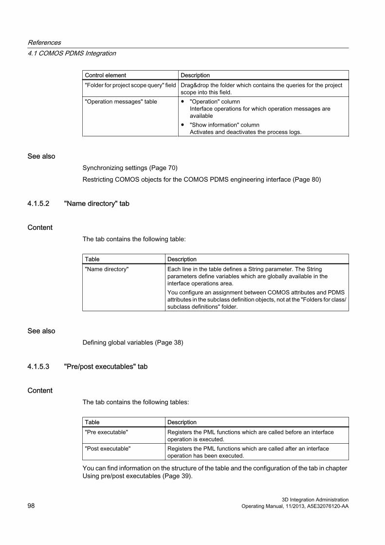
Control element Description"Folder for project scope query" field Drag&drop the folder which contains the queries for the project
scope into this field."Operation messages" table ● "Operation" column
Interface operations for which operation messages are available
● "Show information" columnActivates and deactivates the process logs.
See alsoSynchronizing settings (Page 70)
Restricting COMOS objects for the COMOS PDMS engineering interface (Page 80)
4.1.5.2 "Name directory" tab
ContentThe tab contains the following table:
Table Description"Name directory" Each line in the table defines a String parameter. The String
parameters define variables which are globally available in the interface operations area.You configure an assignment between COMOS attributes and PDMS attributes in the subclass definition objects, not at the "Folders for class/subclass definitions" folder.
See alsoDefining global variables (Page 38)
4.1.5.3 "Pre/post executables" tab
ContentThe tab contains the following tables:
Table Description"Pre executable" Registers the PML functions which are called before an interface
operation is executed."Post executable" Registers the PML functions which are called after an interface
operation has been executed.
You can find information on the structure of the table and the configuration of the tab in chapter Using pre/post executables (Page 39).
References4.1 COMOS PDMS Integration
3D Integration Administration98 Operating Manual, 11/2013, A5E32076120-AA

4.1.5.4 "Character mapping" tab
ContentThe tab contains the following table:
Table Description/ Defines which characters are permitted in COMOS but not in PDMS
and are replaced during name mapping.
You can find information on the structure of the table and the configuration of the tab in chapter Using character mapping (Page 41).
4.1.5.5 "Unit mapping" tab
ContentThe tab contains the following table:
Table Description/ Defines how units in PDMS and COMOS are mapped to one another
if a different unit has been assigned to an attribute in COMOS than in PDMS.
You can find information on the structure of the table and the configuration of the tab in chapter Using unit mapping (Page 41).
4.1.5.6 "Site mapping" and "Zone mapping" tabs
ContentThe tabs contain the following tables:
Table Description of the tableTable for site mapping Defines how the SITE is found in PDMS for a
COMOS object under which the object may be located.
Table for zone mapping Defines how the ZONE is found in PDMS for a COMOS object under which the object may be located.
You can find information on the structure of the tables and the configuration of the tabs in chapter Using ZONE mapping and SITE mapping (Page 42).
References4.1 COMOS PDMS Integration
3D Integration AdministrationOperating Manual, 11/2013, A5E32076120-AA 99

4.1.6 Attributes of the subclass definition objects of classes "Cable" and "Tagged item"
4.1.6.1 "General" tab
"Base object for creating objects" control group
Field Description"Create in unit tree" Master object, e.g. which is to be used for the
import from PDMS to generate objects of this subclass in COMOS.
"Create in location tree" Master object, e.g. which is to be used for the import from PDMS to generate objects of this subclass in COMOS.
See also chapter Defining the base object for the creation of interface objects (Page 46).
"Structural behavior" control group
Control element Description"Creation mode" list This is where you define whether the COMOS
object connected to the PDMS interface object is located in the unit tree or in the location tree.See also chapter Defining structural behavior (Page 45).
"Assign mode" list This is where you define whether the COMOS interface object references another COMOS object and if the referenced object is located in the unit tree or in the location tree.See also chapter Defining structural behavior (Page 45).
Table "PDMS element type" column:List with the PDMS element types which are permitted for the draft objects for which DocLinks are created."Name" column:Types of PDMS objects to which the subclass is applied.See also chapter Defining PDMS element types (Page 45).
See alsoAlgorithm for generating a COMOS path name (Page 59)
References4.1 COMOS PDMS Integration
3D Integration Administration100 Operating Manual, 11/2013, A5E32076120-AA

4.1.6.2 "Name mapping" tab
ContentThe tab contains the following tables:
Table Purpose"Site mapping" Table which defines site mapping."Location mapping" Table which defines location mapping."Level rules" Table which defines deviations from the standard procedures for site
mapping and location mapping.
Information on the structure and configuration of the tables:
● Chapter Name mapping (Page 23)
● Chapter Configuring level rules (Page 64)
● Chapter Configuring site mapping and location mapping in name mapping (Page 57)
4.1.6.3 "Restrictions for owners" tab
ContentThe tab contains the following attributes:
Control element Purpose"Element type of owner" list
List in which you define the element type of the owner of the connected PDMS object.
Table 1 Table in which you define expressions which have to be evaluated to "True" at the owner.
Table 2 Table in which you define filters which check whether a given owner attribute contains a specific occur string.
You can find information on the structure of both tables and the configuration of the tab in chapter Auto-Hotspot.
4.1.6.4 "Model" tab
ContentThe tab contains the following attributes:
Control element Purpose"Mode" list You specify the model type here."Function" field Function call for generating the model.
References4.1 COMOS PDMS Integration
3D Integration AdministrationOperating Manual, 11/2013, A5E32076120-AA 101

Control element Purpose"Element" field Name of the PDMS element whose model is copied."GTypes for filtering" GTypes of the design templates offered for this subclass.
Delimiter: ";"
"Design templates" control group
List DescriptionMain document template List from which you select a design template for the main equipment.
The entries in the list are filtered based on the entries in "TMPFILTER".The list is empty if the entry "EQUI" is missing in "TMPFILTER".
"Sub template" The design templates for the secondary equipment.The entries in the list are determined by the main template set in "PDMS004".
See alsoConfiguring the model (Page 49)
4.1.6.5 "Name directory" tab
ContentThe tab contains the following table:
Description of the table Purpose"Name directory" Definition of String parameters
You can find information on the structure of the table and the configuration of the tab in chapter Working with String Parameters in the name directory (Page 50).
References4.1 COMOS PDMS Integration
3D Integration Administration102 Operating Manual, 11/2013, A5E32076120-AA

4.1.7 Attributes of the subclass definition objects of the "Query" class
4.1.7.1 The "General" tab
"PDMS settings" control group
Control element Description"PDMS name" field Name which users will see when the query is
offered for execution in PDMS."Description" field Description with which the query is displayed in
PDMS once the user has selected it for execution.
"Output format" control group
Control element Description"Output format" list Output format in which the result list of the query
will be transferred to PDMS."Separator" field Only set if the output format is "CSV".
The separator can be chosen at will.
"Main query" control group
Control element Description"Query object" field Reference to the query object whose content is to
be displayed in PDMS."Start object" field Optionally: Reference to a start object.
Overwrites the start object set in the query referenced in the "Name" field.
"Base objects" table Optionally: References to the base objects according to which the query filters the result list.You can set other base objects than those set in the query referenced in the "Name" field.
References4.1 COMOS PDMS Integration
3D Integration AdministrationOperating Manual, 11/2013, A5E32076120-AA 103

"Query for start objects" control group
Control element Description"Query object" field Reference to the query returned by the list of
possible start objects for the main query in PDMS."Start object" field Optionally: Reference to a start object for the start
object query.Overwrites the start object set in the query referenced in the "Name" field.
"Base objects" table Optionally: References to the base objects according to which the query filters the result list.See "BaseObjectsMQ".
See alsoConfiguring a subclass definition object for queries (Page 66)
4.1.8 Attributes of the subclass definition objects of the "Document" class
4.1.8.1 "General" tab
Content
Control element Description"Document ID" field Name of the string parameter which
reads out from PDMS the name of the COMOS document under which the DocLinks are imported.
"Document type" list The document types are used as filters to speed up the search for the COMOSdocument.
"Base object for document search" field Reference to the base object of the COMOS document.The base object is used as a filter to speed up the search for the COMOS document.
"Base object" field Reference to the start object under which the search for the COMOS document is carried out.The base object is used as a filter to speed up the search for the COMOS document.
References4.1 COMOS PDMS Integration
3D Integration Administration104 Operating Manual, 11/2013, A5E32076120-AA

Control element Description"Filter unnamed objects" option Option for filtering the result list of the "Export to
Comos" window.Activated: The result list contains only objects with names.
Table "PDMS element type" column:List with the PDMS element types which are permitted for the draft objects for which DocLinks are created."Name" column:Types of PDMS objects to which the subclass is applied.See also chapter Defining PDMS element types (Page 45).
4.1.8.2 "Restrictions for owners" tabSee also chapter "Restrictions for owners" tab (Page 101).
4.1.8.3 "Name directory" tabSee also chapter "Name directory" tab (Page 102).
4.1.9 Attributes of the interface objects
4.1.9.1 Attributes of the "External 3D Interface" tab
FunctionCOMOS objects require the "External 3D interface" tab in order to be used as an interface object.
The COMOS PDMS Interface evaluates this tab whenever it processes interface objects. Without this tab, the object is not processed.
DatabaseIn the database, tabs have been prepared for the following interface objects:
● Objects of "Tagged item" class
● Objects of "Cable" class
● For nozzles
The tabs for these objects are located in the following catalog:
"@40 > A20 > Y00 > A10 > A10 > Y00T00012 > A03 > B01 Tabs PI-objects"
References4.1 COMOS PDMS Integration
3D Integration AdministrationOperating Manual, 11/2013, A5E32076120-AA 105

From here, they are inherited by the PID device catalog in the database.
System-internal attributesThe following attributes are used system-internally. Do not configure or delete them:
● "ComosCheckUID Check SystemUID"
● "PDMSNAME Name of the corresponding object in PDMS"
● "PDMSRefNo Reference number"
Remaining attributesDefine the following properties of the interface object on the "External 3D Interface" tab:
● The class and subclass
● The PDMS element type
● The model of the object
Details regarding the corresponding attributes and their configuration: See the links below.
See alsoAssigning the class, subclass, and PDMS element type (Page 72)
Overwriting the inherited model information (Page 73)
4.1.10 Attributes of the design template objects
4.1.10.1 Attributes of the "External 3D Interface" tab
ContentThe tab contains the following attributes:
Field Description"PDMS GTYPE" GType of the design template"Purpose" Purpose of the design template
References4.1 COMOS PDMS Integration
3D Integration Administration106 Operating Manual, 11/2013, A5E32076120-AA

"Design parameter" control group
Field Description"DP 01" to"DP 10"
Field in which the value of the corresponding design parameter is entered.Can be modified by the user in the engineering data.
/ Field for the description of the design parameter from PDMS.
The following attributes are dynamically created while the template object is being created in the engineering data:
Field Description/ Is only generated if one or more design templates for secondary equipment
were specified for an interface object:● "<x>": Defines which of the five possible sub templates the current sub
template belongs to.● "<y>": Several templates are available for selection for each item of
secondary equipment. "<y>" designates the template to which the attribute refers.
● Value: The Catref of the sub template selected at the interface object.
4.1.11 "PDMS" categoryThe category defines the following project parameters:
Description Purpose"Initialization file" field Directory containing the INI file."Exchange directory" field These fields cannot be edited. Their content is taken from the
configuration file."Communication directory" field"Document path" field"Configuration path" field The configuration path cannot be edited. It is taken from the
configuration file."Interface active" option Button to activate COMOS PDMS Interface.
See alsoSpecifying interface-relevant directories (Page 16)
References4.1 COMOS PDMS Integration
3D Integration AdministrationOperating Manual, 11/2013, A5E32076120-AA 107

4.2 COMOS 3D viewing
4.2.1 "Tag Script Editor" windowIn this window, you create scripts which you use within configurations for tagging objects. The tags are required to assign COMOS objects and objects from a 3D application to each other, such as COMOS Walkinside.
"Script error" control groupDisplays compilation errors.
References4.2 COMOS 3D viewing
3D Integration Administration108 Operating Manual, 11/2013, A5E32076120-AA

"Tag preview" control group
Control element Description"COMOS start node" field Indicates which start node you selected in the
configuration."Script parameters" field Indicates which script parameters you selected in
the configuration. See also chapter Editing tag scripts (Page 89).
"Object" column Shows a maximum of ten randomly determined objects from the selected quantity of objects.
"Tag" column Indicates which tag is created for an object based on the created script.
"Preview" buttonApplies the script to the selected quantity of objects and displays the result in the "Tag preview" control group. The results are not saved, they are merely used for simulating the tagging.
4.2.2 "Walkinside Object Assignment" plugin
References4.2 COMOS 3D viewing
3D Integration AdministrationOperating Manual, 11/2013, A5E32076120-AA 109

Section for Categories
Number Description1 ● "Create new configuration" button
See also chapter Creating a configuration on the COMOS side (Page 86).● "Update configuration list" button
Updates the configuration list. Application case: e.g. if several users are using the database at the same time
● "Deletes all selected configurations" buttonIs active only if you selected several configurations. Deletes the selected configurations.
2 ● "Creates COMOS tag lists for selected configurations" buttonIs active only if you selected several configurations. Creates a list of the selected objects and their tags. This list is stored in the selected SQLite database.
● "Creates match lists for the selected configurations" buttonIs active only if you selected several configurations and if the configurations received a tag on the COMOS side as well as on the Walkinside side. Assigns the COMOS objects and the objects in Walkinside to each other. The assignment is stored in the selected SQLite database.
● "Show/hide 3D system columns" buttonHides the columns for information on the Walkinside side.
3 "Select the file for the link database" buttonOpens an Explorer view in which you can select or create an SQLite file.
4 The circles indicate the status of the following lists:● 3D tag list● Link list● COMOS tag listColors● Green/red: A list was created. Errors occurred in the process● Red: Could not create a list because errors occurred.● Yellow: A list is currently being created.● Green: A list was correctly created.● White: The creation of a list has not been started yet.
5 ● "Edit this COMOS tag script" buttonOpens the "Tag script editor" window. See also chapter "Tag Script Editor" window (Page 108).
● "Displays a list of preview tags" buttonShows the list, which is also displayed in the "Tag script editor" window, when you start the preview.
● "Creates the COMOS tag list using the script" buttonBased on the script, a tag is created for all selected COMOS objects and stored in the SQLite database.
6 ● "Starts the matching process for this configuration" buttonIs active only if the configuration received a tag on the COMOS side as well as on the Walkinside side.
● "Copies this configuration" buttonSelf-explanatory
● "Deletes this configuration" buttonSelf-explanatory
References4.2 COMOS 3D viewing
3D Integration Administration110 Operating Manual, 11/2013, A5E32076120-AA

Script Library
Number Description7 "System" list
Filters the scripts in the script library by the system in which they were created.8 "Category" list
Contains all the categories which you defined for the scripts in the library. The list also serves as edit field during the creation of scripts in order to define the category of a script.It is used to filter the scripts according to their category.
9 "Creates a new script" buttonIs active only after you enter a name in the "Script name" field.
10 Script Library
4.2.3 "COMOS AutoAssign Configuration" pluginThis window is located on the Walkinside side. See also chapter Creating a configuration on the Walkinside side (Page 88).
1 Script Library2 Categories
The "COMOS AutoAssign Configuration" plugin has a similar design as the "Walkinside Object Assignment" plugin on the COMOS side. See also chapter "Walkinside Object Assignment" plugin (Page 109).
References4.2 COMOS 3D viewing
3D Integration AdministrationOperating Manual, 11/2013, A5E32076120-AA 111

4.2.4 Project properties
"Process Development > Pipe Spec Designer" CategoryThe "3D view" category contains the following control element:
Field Description"Link database:" Here you enter the path to the SQLite database which you want
to use for the creation of configurations. When you enter a path, it is copied into the plugins "Walkinside Object Assignment" and "COMOS AutoAssign Configuration".See also chapters "Walkinside Object Assignment" plugin (Page 109) and "COMOS AutoAssign Configuration" plugin (Page 111).
4.2.5 Sample scripts
4.2.5.1 Sub OnProjectOpen(Project)Sub OnProjectOpen(Project) 'Check if Comos3DView already is runningIf Workset.Globals.ItemExist("Comos3DView") Then If IsObject(Workset.Globals.Comos3DView) Then Set c3d = Workset.Globals.Comos3DView 'msgbox "3D View already present" End IfEnd If 'Check if Comos3DView has to be created newbCreatec3d = FalsebCreatec3d = isEmpty(c3d ) If Not bCreatec3d Then If IsObject(c3d ) Then If c3d Is Nothing Then bCreatec3d = true End IfEnd If 'Create new Comos3DViewIf bCreatec3d Then Set c3d = Createobject("Comos.C3DView.Comos3DView") If Not c3d Is Nothing Then c3d.Init(Workset) Workset.Globals.Comos3DView = c3d 'msgbox "New 3D View present" End IfElse
References4.2 COMOS 3D viewing
3D Integration Administration112 Operating Manual, 11/2013, A5E32076120-AA

'msgbox "No 3D View present"End If End Sub
See alsoActivating "COMOS Walkinside Integration" in COMOS (Page 84)
4.2.5.2 "COMOS.C3DView.config" file<configuration> <appSettings> <add key="StartInterface" value="1" /> <add key="WorkingDirectory" value="C:\exchange\" /> <add key="DEBUG" value="0" /> <add key="DataBasePath" value="C:\WalkinsideNavigation\database.s3db" /> </appSettings></configuration>
Parameter description
Parameter DescriptionStartInterface 1: Interface to Walkinside can be started
0: Interface to Walkinside cannot be startedWorkingDirectory Exchange directory in which communication with
the 3D application is to take place. The specified directory must exist.
DEBUG Specifies whether an extended debug output is to be performed.The default value is 0, which indicates no debug output is to be performed.If you select the value 1, the XML messages being exchanged between COMOS and the 3D application are written to the debug output.
DataBasePath Path to the SQLite database that contains the assignment of the objects. The path must have been specified so that the user can navigate between COMOS and COMOS Walkinside.
See alsoActivating "COMOS Walkinside Integration" in COMOS (Page 84)
Providing link list to users (Page 94)
References4.2 COMOS 3D viewing
3D Integration AdministrationOperating Manual, 11/2013, A5E32076120-AA 113


![A microfluidic-based PDMS prism for SPR imaging system · integration micro-optical element by hollow PDMS prism[7]. PDMS prism if used in imaging SPR sensors abolishes using the](https://img.pdfslide.us/doc/110x75/5e461215795b545e6926d976/a-microfluidic-based-pdms-prism-for-spr-imaging-system-integration-micro-optical.jpg)