Embed Size (px)
Citation preview
3D head anthropometric analysis
Reyes Enciso*ab, Alex Shawa, Ulrich Neumannb, and James Maha
a School of Dentistry, Univ. Southern California, 925 West 34th St, Los Angeles CA 90089-0641;b Integrated Media Systems Center, USC, 3740 McClintock Ave., Los Angeles, CA 90089-2561
ABSTRACT
Currently, two-dimensional photographs are most commonly used to facilitate visualization, assessment and treatmentof facial abnormalities in craniofacial care but are subject to errors because of perspective, projection, lack metric and 3-dimensional information. One can find in the literature a variety of methods to generate 3-dimensional facial imagessuch as laser scans, stereo-photogrammetry, infrared imaging and even CT however each of these methods containinherent limitations and as such no systems are in common clinical use. In this paper we will focus on development ofindirect 3-dimensional landmark location and measurement of facial soft-tissue with light-based techniques. In thispaper we will statistically evaluate and validate a current three-dimensional image-based face modeling technique usinga plaster head model. We will also develop computer graphics tools for indirect anthropometric measurements in athree-dimensional head model (or polygonal mesh) including linear distances currently used in anthropometry. Themeasurements will be tested against a validated 3-dimensional digitizer (MicroScribe 3DX).
Keywords: anthropometry, face, 3D reconstruction, three-dimensional, digitizer
1. INTRODUCTION
Diagnosis and treatment planning of craniofacial anomalies involve the processes of visualization and analysis. In theseprocesses, deviations from the norm, asymmetries and affected structures are realized for comprehensive treatmentplanning. By enlarge, the majority of this activity is based on visual evaluation, two-dimensional photographs andradiographs, and to a lesser extent CT slice data. Within this system, recording and analysis of facial form are conductedgenerally in 2-dimensions and constrained to the limitations of the technology. Effective solutions to 3-dimensionalfacial image acquisition and analyses could have significant benefit20. Therefore, the aims of this paper are to developand refine instrumentation to enable these approaches to clinical care.
In this paper we acquired and validated 3-dimensional images of a plaster head using structured-light image-basedtechniques and developed computerized methods for indirect measurements based on Farkas’ extensive work in thefield9 for assessment of craniofacial form (including facial asymmetries).
Previous reports have demonstrated 3-dimensional facial imaging in a clinical setting however some of theanthropometric measurements were proven to be unreliable (errors higher than 1.5mm)1; 4. In addition, recent advancesin imaging systems have made 3-dimensional imaging accessible to many healthcare professionals, yet these systemslack validation for specific clinical purposes. Therefore, our goal is to validate a structured-light imaging system using amannequin head with pre-labeled anthropometric markers.
* [email protected]; phone 1 213 740 8134; fax 1 213 740 5715; http://graphics.usc.edu/~renciso.

2. BACKGROUND
2.1 Facial imaging technologies in craniofacial care
Imaging modalities for clinical evaluation of the face, such as photographs and two-dimensional radiographic films(used since 1931) were developed decades ago and are still in mainstream clinical use. However, the information theyprovide is limited in perspective, accuracy, and contains information voids. For these reasons, in the last decades, three-dimensional techniques such as 3D CT, laser surface scanning, photogrammetry (conversion of photographs taken fromdifferent views into 3D models), Moire’ stripes18, and Computer Assisted Design (CAD) manipulation of these modelshave been explored.
CT Scans: Computed tomography (CT scan) has much of its history in general medicine while its use in craniofacialassessment is more recent. In this area, the bulk of the research work is focused upon bony cranial landmarks. Previouswork reported the use of 3D CT for craniofacial surgical planning36 and comprehensive assessment of hemifacialmicrosomia38. Richtsmeier and her research group21 developed mathematical tools such as EDMA (Euclidean DistanceMatrix Analysis) to assess asymmetry in human skulls, detection of influencial landmarks22 and confidence intervals23.The authors also assessed the localization error of landmarks in human skulls using CT scans32 to be less than 0.5mm.This is the repeatability error only. As the authors pointed out the reported localization error of 0.5 mm is in idealconditions when the soft tissue is removed before digitizing. Later, vitro skull landmark measurements made with adigitizer were compared to the CT data and a mean error of 0.87mm and a maximum error of 2mm was found4. The costand radiation received by the patient during a CT make this technique no suitable for our research.
Laser facial scanning: Technologies for generating a 3-dimensional model of a human face with registered textureinclude laser scanning and visible light techniques. The laser scanners produce a detailed model but the digitizationprocess requires the subject to remain still for a period of several seconds to a minute or more while the scanner headrevolves around the subject’s head. In addition, the output can be noisy thus requiring additional processing to treatnoise, outliers, and holes.Researchers have explored the use of laser surface scanning for assessment of facial asymmetry5; 25; 27. The authorsdivided the face in different regions and then classified the pre-surgical and post-surgical areas according to differentsurface type primitives: valley, ridge, saddle surface, etc. The quantitative changes per region are expressed in terms ofarea size changes and their movement on the face. The reported precision of the laser scanning device is approximately0.5 mm, and time of exposure is 10 seconds. While the authors claim that these measurements in terms of area regionsare more adapted to clinical evaluation of the treatment outcome, anthropometric measurements as described in9 aremore widely used in craniofacial care. Researchers1 have compared laser scanned anthropometric measurementscomputed with the same equipment as in26 with direct physical ones and found out that more than half were unreliable(errors higher than 1.5mm).
The accuracy of lasers (Cyberware) in imaging plastic and plaster heads have also been reported3 as 0.6mm variance oflocalization in the three axes when using pre-labeled landmarks. The authors used 22 anthropometric landmarksinteractively selected by a user in the image of the plaster’s head model. When not using pre-labeled landmarks on theplaster head, the error of localization of the anthropometric landmarks reported is within 2mm.
Stereo-photogrammetry: In 1960 dot stereograms and the idea that stereoscopic vision is a cooperative process wereintroduced16. A algorithm for stereo reconstruction followed24. The use of stereo in medicine was first reported in astudy of facial asymmetry with a dry skull6. Stereo-photogrammetry has also been used to find the optimal plane ofreference for assessment of craniofacial anomalies such as cleft lip and palate30 and for quantification and validation ofthe linear and angular measurements using only eight pairs of landmarks31. The absolute value of the reproducibilityerror for localizing the landmarks reported was 1mm and 1.1 degrees for the angles31. Recently, Ferrario et al.11; 13-15
published their work in stereo-photogrammetry with two CCD cameras working in the infrared fields to automaticallylocate 22 facial landmarks (retroreflective markers on the face) providing anthropometric information (linear distances,angles and one ratio). The error in reproducibility of a landmark and marker location found was less than 2mm.
Commercial visible-light imaging systems: Fixed viewpoint depth maps are created from stereo-photogrammetrysystems (Geometrix’s Face 200 and 800) and structured-light camera systems (such as Eyetronics, 3DMD and Inspeckrequiring a slide projector and one or more cameras). To produce a full face model (from ear to ear) with these systems,two or three depth maps are obtained for a subject from varying view points (e.g., left-side, right-side, and frontal) andstitched together with manual assistance. The only commercially available system that acquires an ear-to-ear model isFace 1200 from Geometrix with 12 cameras. Given the current state, a fast, efficient, reliable, non-invasive solution to3-D facial image acquisition would be a very significant step forward. A system such as this would eliminate many ofthe barriers for clinicians to obtain and use such as system. Today, no 3-D systems are in common clinical use, whiletraditional photography is the standard.
2.2 Study of cranial form and asymmetry
Landmarks have been used for over a century by anthropometrists interested in quantifying cranial variation. A newfield, morphometrics, has grown around the statistical analysis of shape and size for comparison of biologicalshapes2; 33; 35. Since the 1930’s clinical application of facial anthropometry has been reported for cleft lip/palate patients,and to examine children with unilateral facial asymmetry8. A recent review of facial anthropometry in cleft patients37
and applications20 in other areas of craniofacial care can be found.
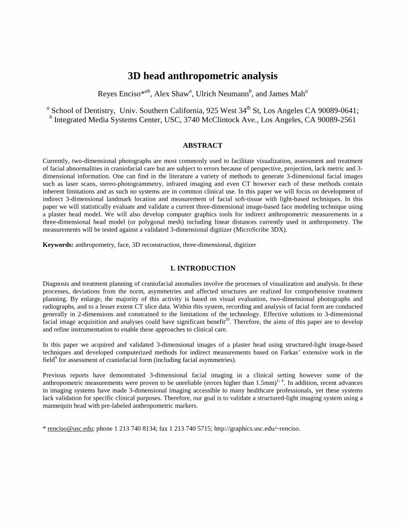
A great body of work in craniofacial anthropometry is that of Farkas who established a database of anthropometricnorms9; 10 by measuring and comparing more than 100 dimensions (linear, angular and surface contour’s) andproportions in hundreds of people over a period of many years. These measurements include 47 landmark points todescribe the face (Figure 1 shows some of the Farkas’ landmarks). The anthropometric data include 129 measurementswith statistical mean and variance tabulated per age and gender. The measurements are acquired with special equipmentused in a consistent fashion (see20 for the methods used to clinically obtain the measurements).
Figure 1: Subset of Farkas’s anthropometric landmarks (frontal and side picture of the mannequin).
Clinical application of facial anthropometry has been limited due to the time required to obtain these measurements (45-60 min.) and the difficulty in comprehensively visualizing the problem given the numerical form of the measurements.Our research aims to develop methods to obtain these measurements in an automatic fashion, allowing clinicians torapidly obtain anthropometric and customized measurements.
2.3. Computer-graphics face modeling and anthropometry
Computer modeling of faces dates from the 1970’s29. Face modeling for artistic and entertainment purposes is nowcommonplace in the computer graphics community. Farkas’s inventory of facial measurements has been used incomputer graphics to automatically create new “plausible” computer graphic faces7. In very recent work the authors17
used the anthropometric norms in Farkas studies for aging simulation and facial animation.
3. METHODS
3.1. Materials and equipment
Markers: Retro-reflective markers visible on a photograph (Figure 1) but also accurately digitized by Microscribe’sdigitizer (Figure 3) will be placed on the mannequin.
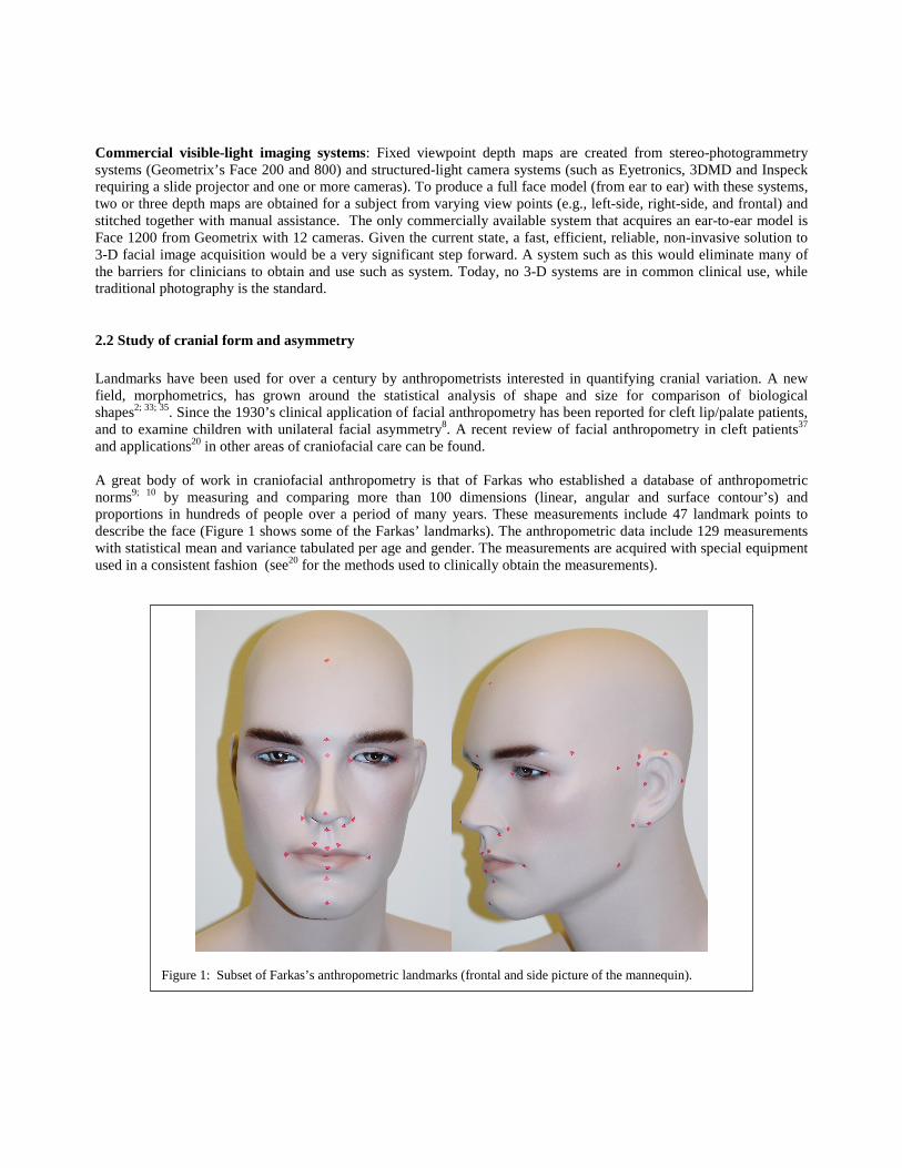
Imaging device: Eyetronics. The light-based imaging system consists of a regular slide projector, a digital camera anda calibration pattern. ShapeMatcherTM (from Eyetronics) software interprets photographs of a pattern projected on theface to build a three-dimensional reconstruction of that view of the face. ShapeSnatcher SuiteTM allows the user to stitchmore than one view to create one single polygonal mesh and texture image (Figure 2).
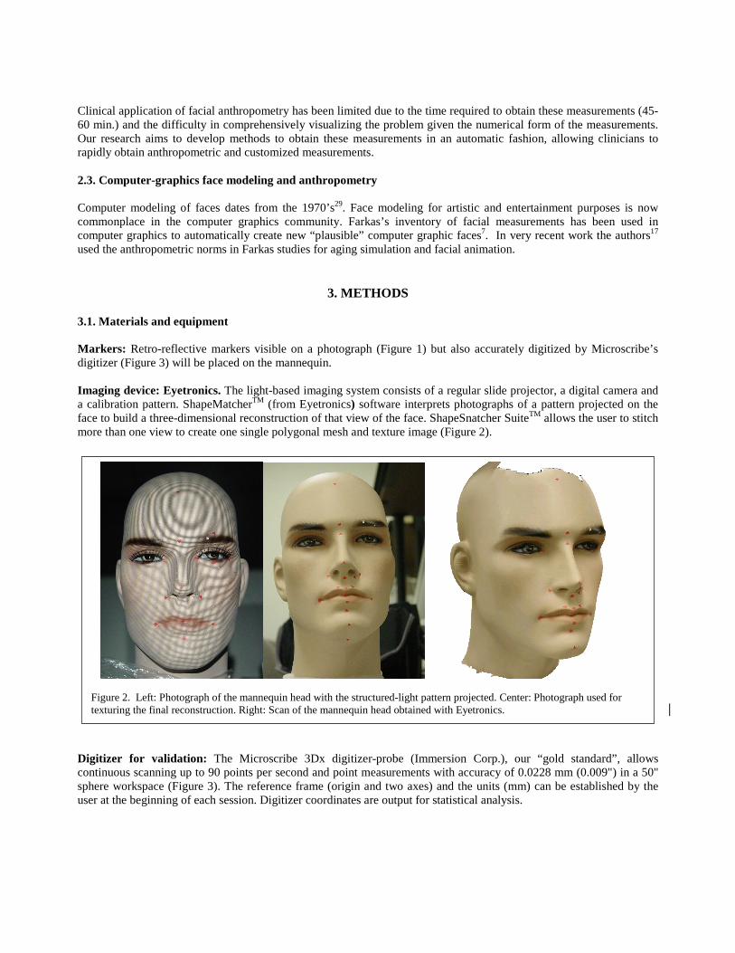
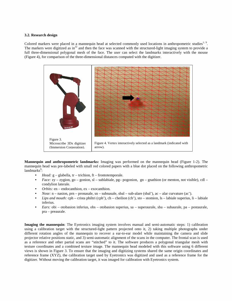
Digitizer for validation: The Microscribe 3Dx digitizer-probe (Immersion Corp.), our “gold standard”, allowscontinuous scanning up to 90 points per second and point measurements with accuracy of 0.0228 mm (0.009") in a 50"sphere workspace (Figure 3). The reference frame (origin and two axes) and the units (mm) can be established by theuser at the beginning of each session. Digitizer coordinates are output for statistical analysis.
Figure 2. Left: Photograph of the mannequin head with the structured-light pattern projected. Center: Photograph used fortexturing the final reconstruction. Right: Scan of the mannequin head obtained with Eyetronics.
3.2. Research design
Colored markers were placed in a mannequin head at selected commonly used locations in anthropometric studies1; 9.The markers were digitized as in32 and then the face was scanned with the structured-light imaging system to provide afull three-dimensional polygonal mesh of the face. The user can select the landmarks interactively with the mouse(Figure 4), for comparison of the three-dimensional distances computed with the digitizer.
Mannequin and anthropometric landmarks: Imaging was performed on the mannequin head (Figure 1-2). Themannequin head was pre-labeled with small red colored papers with a blue dot placed on the following anthropometriclandmarks9:
• Head: g – glabella, tr – trichion, ft – frontotemporale.• Face: zy – zygion, go – gonion, sl – sublabiale, pg– pogonion, gn – gnathion (or menton, not visible), cdl –
condylion laterale.• Orbits: en – endocanthion, ex – exocanthion.• Nose: n – nasion, prn – pronasale, sn – subnasale, sbal – sub-alare (sbal’), ac – alar curvature (ac’).• Lips and mouth: cph – crista philtri (cph’), ch – cheilion (ch’), sto – stomion, ls – labiale superius, li – labiale
inferius.• Ears: obi – otobasion inferius, obs – otobasion superius, sa – superaurale, sba – subaurale, pa – postaurale,
pra – preaurale.
Imaging the mannequin: The Eyetronics imaging system involves manual and semi-automatic steps: 1) calibrationusing a calibration target with the structured-light pattern projected onto it, 2) taking multiple photographs underdifferent rotation angles of the mannequin to recover a ear-to-ear model while maintaining the camera and slideprojector relative positions static, and 3) semi-automatic alignment of the scans in the computer. The frontal scan is usedas a reference and other partial scans are “stitched” to it. The software produces a polygonal triangular mesh withtexture coordinates and a combined texture image. The mannequin head modeled with this software using 6 differentviews is shown in Figure 3. To ensure that the imaging and digitizing systems shared the same origin coordinates andreference frame (XYZ), the calibration target used by Eyetronics was digitized and used as a reference frame for thedigitizer. Without moving the calibration target, it was imaged for calibration with Eyetronics system.
Figure 4. Vertex interactively selected as a landmark (indicated witharrow).
Figure 3.Microscribe 3Dx digitizer(Immersion Corporation).

Interactive landmark identification: Our own software based on OpenGl, C++ and MFC allows for interactiveclicking with the mouse of any vertex in a polygonal mesh and highlights it for verification. This interface allows forscaling, rotation and translation of the object for best identification of the landmarks from any viewpoint.
Indirect anthropometric measurements: After identification and localization of the anthropometric landmarks (Figure4) we computed the 3D Euclidian distance between landmarks.
3.3. Statistical validation
We followed the research design outlined by Kohn and Cheverud19 forvalidation of errors in imaging systems, also used32 for validation of CTmeasurements with a digitizer.
Imaging Research Design: A digital model of the mannequin head wascreated. Then two operators in two sessions (Session 1 and 2) 24 hours a parttwice interactively marked the landmarks in the digital 3D model twice (L1 andL2) to test for marking error. This design (Figure 5) will allow us to computeprecision and reproducibility of the imaging error from the interactivelandmark’s marking error.
Digitization Process: In a separate process the head’s landmark markers weredigitized during two sessions (Session 1 and 2) by each operator 24 hours apartto compute intraobserver and interobserver error of landmark localization. Eachlandmark was digitized 10 times twice (D1 and D2) for validation of therepeatability of the digitizing process and precision (Figure 6). Precision wasdefined as the average absolute difference between repeated measures of thesame landmark.
4. PRELIMINARY RESULTS
Precision of the digitizer: Two operators digitized ten times the two visible corners of a 10 cm ruler in horizontal andvertical positions in two sessions. For the landmark coordinates (X, Y and Z of each corner of the ruler) we found amaximum standard deviation for both sessions combined for the two operators of 0.27mm, and maximum variance of0.07. We validated the mean length of the ruler as: a) 100.15 mm with standard deviation of 0.22 mm and variance of0.05 in horizontal position and b) 100.4 mm with standard deviation of 0.32 mm and variance of 0.10 in verticalposition.
Errors in landmark identification in the computer: To validate the process of landmark localization using thecomputer, two operators interactively selected the landmarks on the 3-D reconstruction of the mannequin’s head. Themean of the difference of the distance between the coordinates selected by the two operators was 0.047 mm withstandard deviation of 0.07 mm and variance of 0.006.
Validation of linear measurements: The validation consists of comparing the results from imaging (Eyetronics) withthose obtained from a physical technique (the digitizer). Because the digitizer is our “gold standard”, differencesbetween homologous measurements define the imaging error. Craniofacial landmarks (n=23) described in section 3.2were digitized and compared with those selected with the mouse on the 3D reconstructions (g, ft, en, ex, zy, go, sl, pg,cdl, n, prn, sn, sbal, sbal’, ac, ac’, cph, cph’, ch, ch’, ls, li, obi, obs, pra). The landmarks tr, gn, sto, sa, pa, sba were notvisible on the image or the 3D reconstruction was inaccurate.Twenty-five homologous linear Euclidean distances were compared with the digitizer for validation. In the frontal area,g-n, n-prn, sn-ls, ls-li, sl-pg were found reliable with imaging error less than 0.5 mm. The distances en-ex (right eye),cph-cph’, ch-ch’ and ac-ac’ were found between 0.5-1.0 mm imaging error, and the distance ch-ch’ had an error of 1.54mm.
Operator (1 or 2)
Session 1 Session 2
L1 L2 L1 L2
Figure 5. Research design forvalidation of imaging system.
Operator (1 or 2)
Session 1 Session 2
D1 D2 D1 D2
Figure 6. Validation of theMicroscribe 3Dx digitizer.

On the left side, we found obs-pra, obs-cdl, obs-obi, zy-go, zy-pra, ft-go and zy-ft with less than 0.5 mm imaging errorand ft-obs had an imaging error of 0.55 mm.On the right side, we found obs-pra, obs-obi, zy-go less than 0.5 mm error, and obs-cdl,, ft-obs and zy-ft between 0.5-1mm, and finally, zy-pra and ft-go with an error between 1.0-1.2mm.
The overall mean absolute error combining frontal, left and right side was of 0.48 mm, with standard deviation of 0.40mm, variance of 0.16, and maximum absolute error of 1.55 mm.
5. CONCLUSIONS
We found the mean absolute error of the light-based imaging system during imaging of twenty-five Euclidian distancesof a mannequin head to be 0.48 mm with maximum error of 1.55 mm. Some of the measurements were found unreliablewith error higher than 1.5 mm. Further research will involve validation of the system by comparing two different imagesof the mannequin created by different operators. Although there is great interest and demand amongst the craniofacialhealthcare community for the use of 3-dimensional models for treatment planning and visualization1; 20; 34 and forquantitative assessment of the asymmetry3; 12; 25; 28; 32, validation of the imaging system is essential for these functions.
ACKNOWLEDGMENTS
The research has been funded in part by the Integrated Media Systems Center, a National Science FoundationEngineering Research Center, Cooperative Agreement No. EEC-9529152, Sun Microsystems and the AmericanAssociation of Orthodontists Foundation.
REFERENCES
1 S. Aung, R. Ngim, and S. Lee, "Evaluation of the laser scanner as a surface measuring tool and its accuracy compared withdirect facial anthropometric measurements," British Journal of Plastic Surgery, 48, 551-558, 1995.
2 F. L. Bookstein, The Measurement of Biological Shape and Shape Change, Berlin Heidelberg New York: Springer-Verlag,1978.
3 K. Bush and O. M. Antonyshyn, "3-dimensional facial anthropometry using a laser-surface scanner-validation of thetechnique," Plastic & Reconstructive Surgery, 98, 6-235, 1996.
4 M. Cavalcanti, J. Haller, and M. Vannier, "Three-dimensional computed tomography landmark measurement in craniofacialsurgical planning: experimental validation in vitro," J Oral Maxillofac Surg, 57, 690-4, 1996.
5 A. Coombes, J. P. Moss, A. D. Linney, R. Richards, and D. R. James, "A Mathematical method for the comparison of three-dimensional changes in the facial surface," European Journal of Orthodontics, 13, 95-110, 1991.
6 N. Crete, Y. Deloison, and R. Mollard."Etude Asymmetries Faciales Par la Methode Stereometrique", Applications of HumanBiostereometrics (NATO), SPIE Vol. 166, 311-319, 1978.
7 D. DeCarlo, D. Metaxas, and M. Stone. "An Anthropometric Face Model using Variational Techniques", Proceedings ACMSIGGRAPH '98, 67-74, ACM SIGGRAPH, 1998.
8 L. G. Farkas and J. S. James, "Anthropometry of the face in lateral facial dysplasia: the unilateral form.," Cleft Palate Journal14, 193-199, 1977.
9 L. Farkas, Anthropometry of the Head and Face, Raven Press, New York, 1994.10 L. Farkas and I. Munro, Anthropometric Facial Proportions in Medicine, 344, Charles C. Thomas, Springfield, Illinois, 1987.11 V. F. Ferrario, C. Sforza, C. Poggio, and J. H. Schmitz, "Soft-tissue Facial Morphometry from 6 Years to Adulthood: A
Three-dimensional Growth Study Using a New Modeling," Plastic & Reconstructive Surgery, 103, 768-778, 1999.12 V. F. Ferrario, C. Sforza, C. Poggio, J. H. Schmitz, and A. Colombo, "Soft tissue morphology related to headform: a three-
dimensional quantitative analysis in childhood," Journal of Craniofacial Genetics & Developmental Biology, 17, 86-95,1997.
13 V. F. Ferrario, C. Sforza, C. Poggio, and G. Serrao, "Facial three-dimensional morphometry," Am J Orthod DentofacialOrthop, 109, 86-93, 1996.
14 V. F. Ferrario, C. Sforza, A. Puleo, C. Poggio, and J. H. Schmitz, "Three-dimensional facial morphometry and conventionalcephalometrics: a correlation study," International Journal of Adult Orthodontics & Orthognathic Surgery, 11, 329-38, 1996.
15 V. F. Ferrario, C. Sforza, J. H. Schmitz, A. Jr. Miani, and G. Serrao, "A three-dimensional computerized mesh diagramanalysis and its application in soft tissue facial morphometry.," American Journal of Orthodontics and DentofacialOrthopedics, 114, 404-413, 1998.
16 B. Julesz, "Binocular Depth Perception of Computer-Generated Patterns," Bell System Tech, 39, 1125-1161, 1960.

17 K. Kahler, J. Haber, H. Yamauchi, and H. Seidel. "Head Shop: Generating Animated Head Models with AnatomicalStructure", ACM Siggraph Symposium on Computer Animation, 55-64, ACM SIGGRAPH, San Antonio, Texas, 2002.
18 T. Kawai, N. Natsume, H. Shibata, and T. Yamamoto, "Three-dimensional analysis of facial morphology using moirestripes.Part I. Methods," Int J Oral Maxillofac Surg, 19, 356-358, 1990.
19 L. Kohn and J. Cheverud. "Calibration, validation, and evaluation of scanning systems: anthropometric imaging systemrepeatability", Electronic imaging of the human body. Proceedings of a working group. Vannier MW, Yates RE Whitestone JJeds. , 114-123, CSERIAC, Dayton:OH, 1992.
20 J. C. Kolar and E. Salter, Craniofacial Anthropometry: Practical Measurement of the Head and Face for Clinical, Surgicaland Research Use, Charles C. Thomas Publisher, LTD, 1997.
21 S. Lele and J. T. Richtsmeier, "Euclidean Distance matrix analysis: a coordinate-free approach for comparing biologicalshapes using landmark data," Am J Phys Anthropol, 86, 415-427, 1991.
22 S. Lele and J. T. Richtsmeier, "On comparing biological shapes- detection of influential landmarks.," Am J Phys Anthropol,87, 49-65, 1992.
23 S. Lele and J. T. Richtsmeier, "Euclidean Distance Matrix Analysis: confidence intervals for form and growth comparison.Amer. J. Phys. Anthropol. 98: (1) 73-86, 1995
24 D. Marr and T. A. Poggio. Cooperative Computation of Stereo Disparity. Science, 194[4262], 283-287, 1976.25 J. P. Moss, A. Coombes, A. D. Linney, and J. Campos, "Methods of three dimensional analysis of patients with asymmetry of
the face," Proc Finn Dental Society, 87, 139-149, 1991.26 J. P. Moss, A. D. Linney, S. R. Grindrod, and C. A. Mosse, "A laser scanning system for the measurement of facial surface
morphology," Optics and Lasers in Engineering, 10, 179-190, 1989.27 J. P. Moss, A. Linney, S. Grindrod, A. SR, and C. JS, "Three-dimensional visualization of the face and skull using
computerized tomography and laser scanning techniques," European Journal of Orthodontics, 9, 247-53, 1989.28 K. F. O'Grady and O. M. Antonyshyn, "Facial Asymmetry: Three dimensional analysis using laser surface scanning.," Plastic
and Reconstructive Surgery, 104, 928-937, 1999.29 F. I. Parke and K. Waters, Computer Facial Animation, A. K. Peters, Wellesley, Massachusetts, 1996.30 F. Ras, L. L. Habets, F. C. Van Ginkel, and B. Prahl-Andersen, "Facial Left-Right Dominance in Cleft Lip and Palate: Three-
Dimensional Evaluation.," Cleft Palate-Craniofacial Journal, 31, 461-5, 1994.31 F. Ras, L. L. Habets, F. C. Van Ginkel, and B. Prahl-Andersen, "Quantification of facial morphology using
stereophotogrammetry - demonstration of a new concept," Journal of Dentistry, 24, 369-74, 1996.32 J. Richtsmeier, C. Paik, P. Elfert, T. Cole, and H. Dahlman, "Precision, repeatability and validation of the localization of
cranial landmarks using computed tomography scans," Cleft Palate-Craniofacial Journal, 32, 217-227, 1995.33 F. Rohlf, "Morphometrics," Annual Rev Ecol Syst, 21, 299-316, 1990.34 G. Santler, H. Kartcher, and C. Ruda, "Indications and limitations of three-dimensional models in cranio-maxillofacial
surgery.," Journal of Cranio-Maxillo-Facial Surgery, 26, 11-16, 1998.35 A. Siegel and R. Benson, "A robust comparison of biological shapes," Biometrics, 38, 341-350, 1982.36 M. W. Vannier, J. L. Marsh, and J. O. Warren, "Three-dimensional CT reconstruction images for craniofacial surgical
planning and evaluation," Radiology, 150, 179-184, 1984.37 F. Vegter and J. J. Hage, "Facial Anthropometry in Cleft Patients: A Historical Appraisal," Cleft Palate Craniofacial Journal,
38, 2001.38 A. Whyte, M. Hourihan, M. Earley, and A. Sugar, "Radiologic assessment of hemifacial microsomia by three-dimensional
computed tomography," Dento-Maxillo-Facial Radiology, 19, 119-125, 1990.