Embed Size (px)
Citation preview
3D Computer Vision
and Video Computing 3D Vision3D Vision
Lecture 14Stereo Vision (I)
CSC 59866CDFall 2004
Zhigang Zhu, NAC 8/203Ahttp://www-cs.engr.ccny.cuny.edu/~zhu/
Capstone2004/Capstone_Sequence2004.html
3D Computer Vision
and Video Computing Stereo VisionStereo Vision
Problem Infer 3D structure of a scene from two or more images taken from
different viewpoints
Two primary Sub-problems Correspondence problem (stereo match) -> disparity map
Similarity instead of identity Occlusion problem: some parts of the scene are visible only in one eye
Reconstruction problem -> 3D What we need to know about the cameras’ parameters Often a stereo calibration problem
Lectures on Stereo Vision Stereo Geometry – Epipolar Geometry (*) Correspondence Problem (*) – Two classes of approaches 3D Reconstruction Problems – Three approaches
3D Computer Vision
and Video Computing A Stereo PairA Stereo Pair
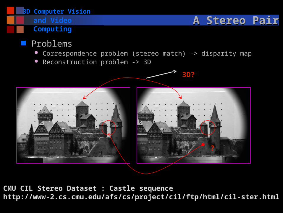
Problems Correspondence problem (stereo match) -> disparity map Reconstruction problem -> 3D
CMU CIL Stereo Dataset : Castle sequencehttp://www-2.cs.cmu.edu/afs/cs/project/cil/ftp/html/cil-ster.html
?
3D?
3D Computer Vision
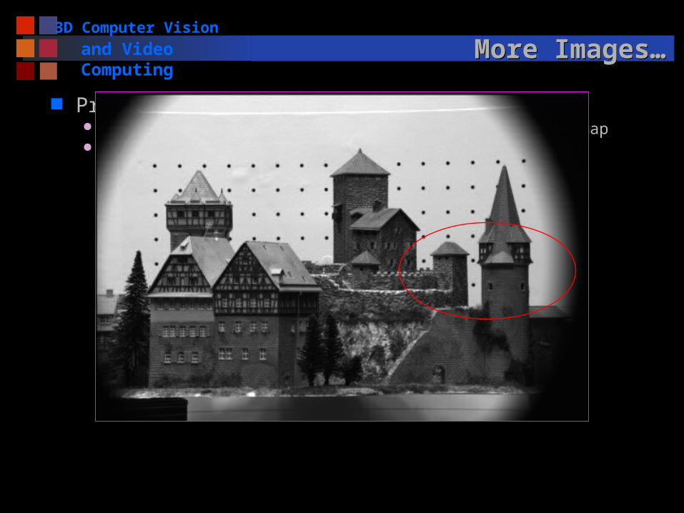
and Video Computing More Images…More Images…
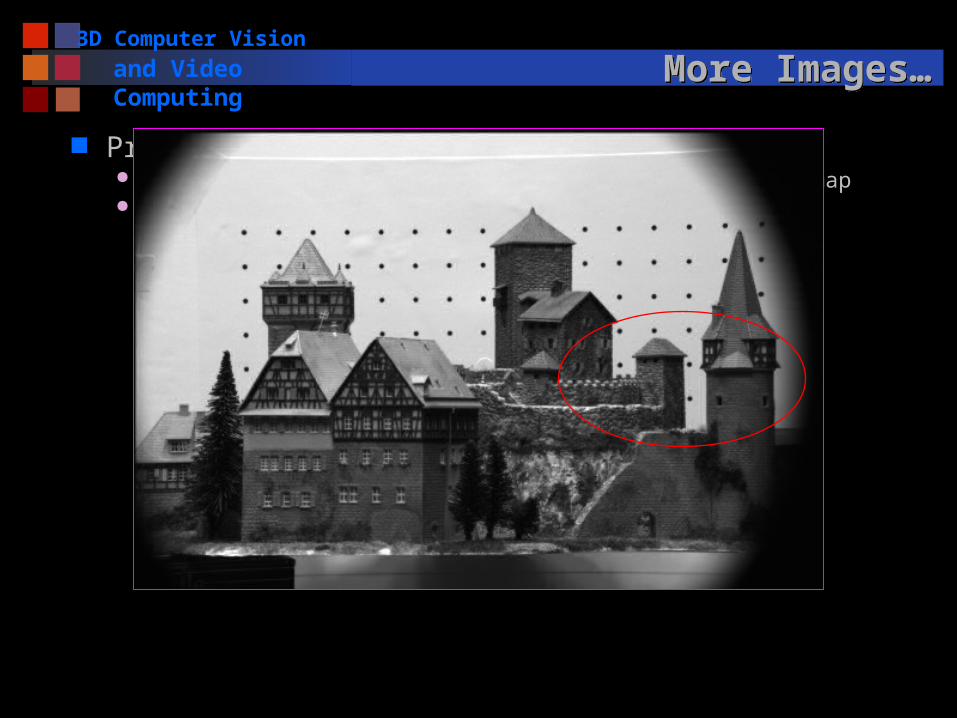
Problems Correspondence problem (stereo match) -> disparity map Reconstruction problem -> 3D
3D Computer Vision
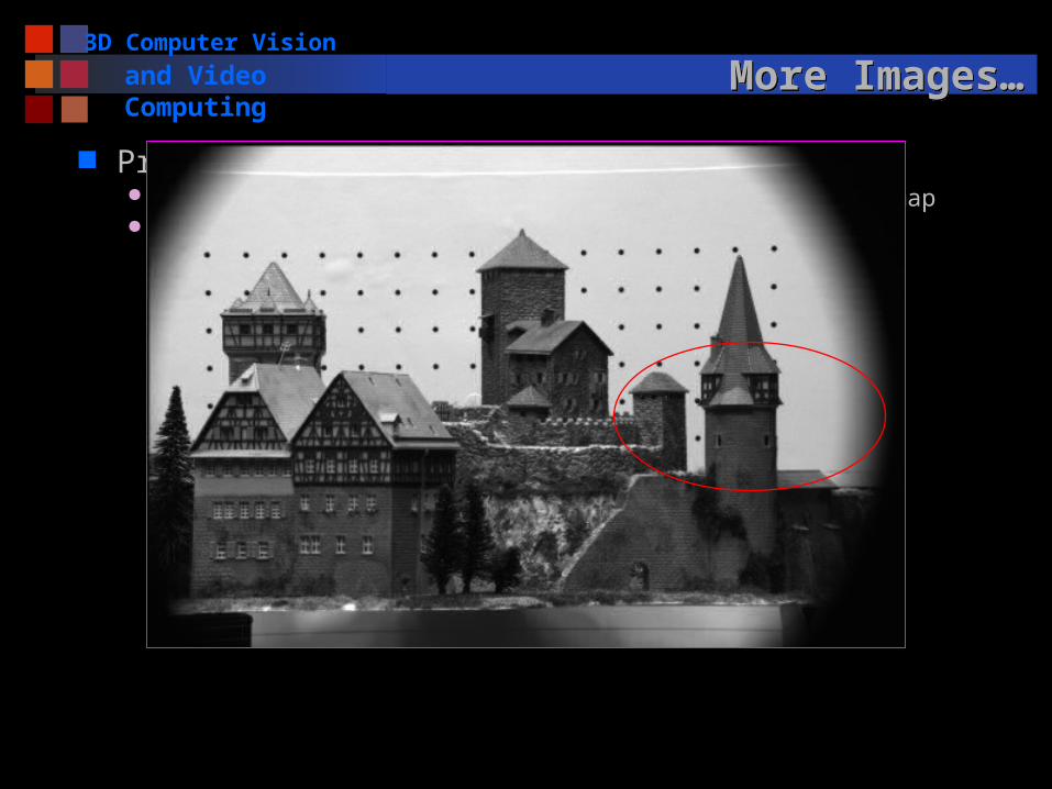
and Video Computing More Images…More Images…
Problems Correspondence problem (stereo match) -> disparity map Reconstruction problem -> 3D
3D Computer Vision
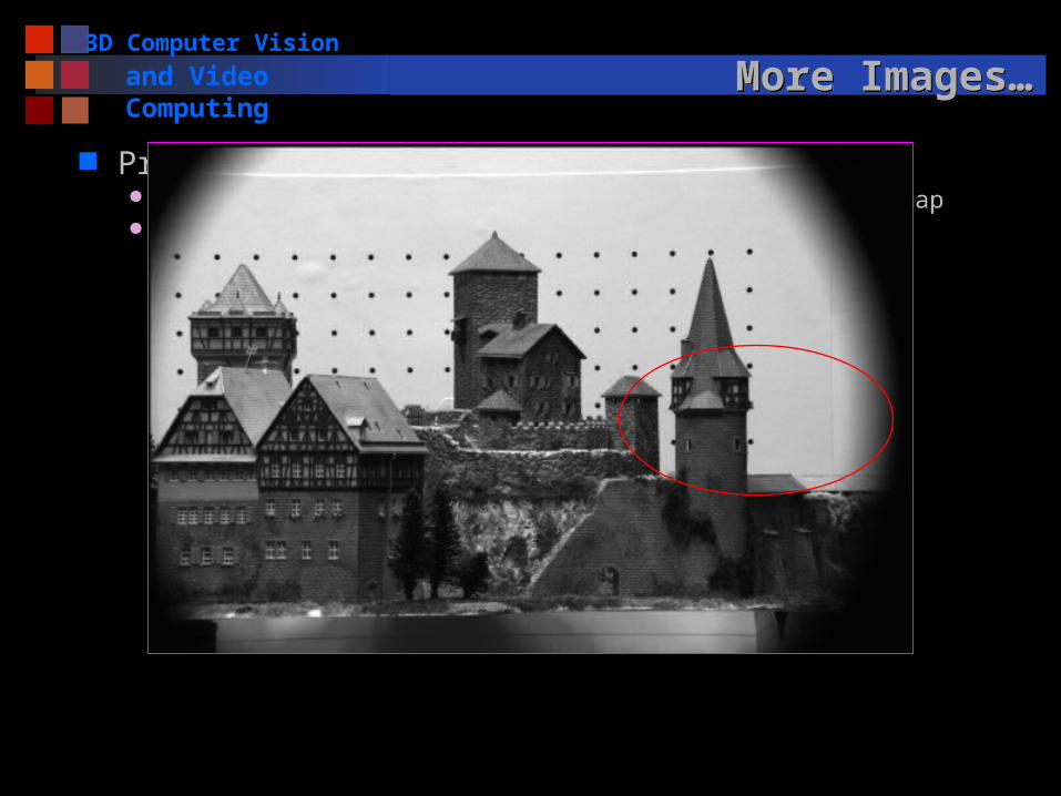
and Video Computing More Images…More Images…
Problems Correspondence problem (stereo match) -> disparity map Reconstruction problem -> 3D
3D Computer Vision
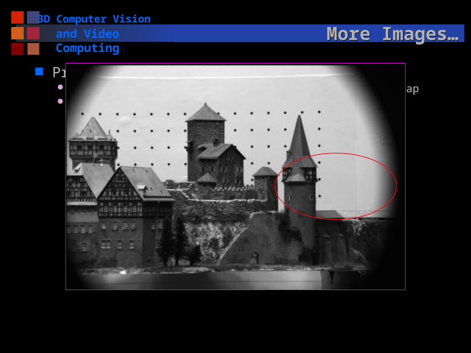
and Video Computing More Images…More Images…
Problems Correspondence problem (stereo match) -> disparity map Reconstruction problem -> 3D
3D Computer Vision
and Video Computing More Images…More Images…
Problems Correspondence problem (stereo match) -> disparity map Reconstruction problem -> 3D
3D Computer Vision
and Video Computing Lecture OutlineLecture Outline
A Simple Stereo Vision System
Disparity Equation Depth Resolution Fixated Stereo System
Zero-disparity Horopter
Epipolar Geometry
Epipolar lines – Where to search correspondences Epipolar Plane, Epipolar Lines and Epipoles http://www.ai.sri.com/~luong/research/Meta3DViewer/EpipolarGeo.html
Essential Matrix and Fundamental Matrix Computing E & F by the Eight-Point Algorithm Computing the Epipoles
Stereo Rectification
3D Computer Vision
and Video Computing Stereo GeometryStereo Geometry
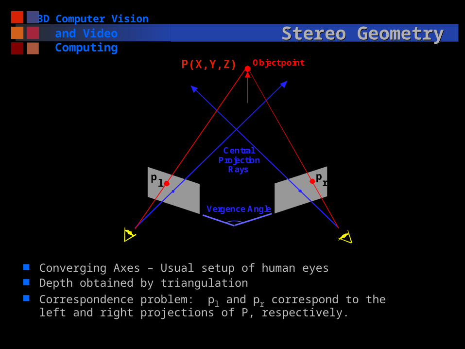
Converging Axes – Usual setup of human eyes Depth obtained by triangulation Correspondence problem: pl and pr correspond to the left and right
projections of P, respectively.
Object point
CentralProjection
Rays
Vergence Angle
pl
pr
P(X,Y,Z)
3D Computer Vision
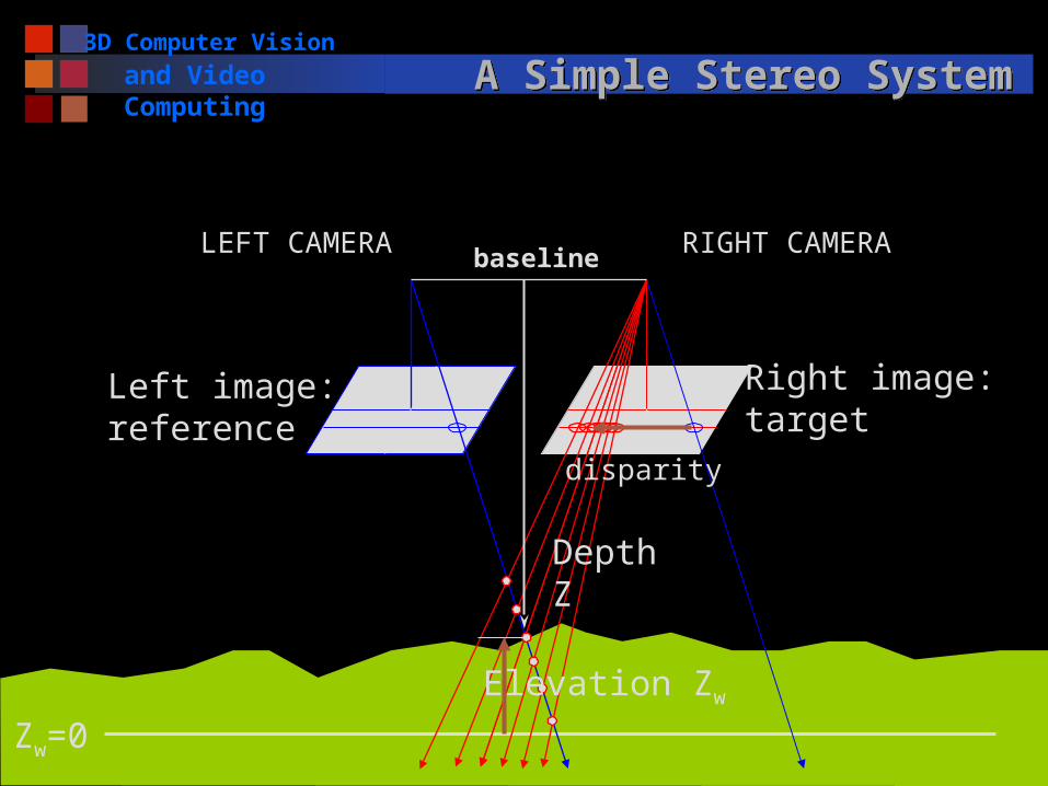
and Video Computing A Simple Stereo SystemA Simple Stereo System
Zw=0
LEFT CAMERA
Left image:reference
Right image:target
RIGHT CAMERA
Elevation Zw
disparity
Depth Z
baseline
3D Computer Vision
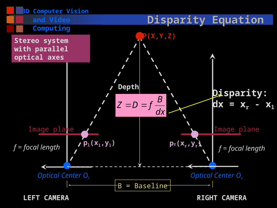
and Video Computing Disparity EquationDisparity EquationP(X,Y,Z)
pl(xl,yl)
Optical Center Ol
f = focal length
Image plane
LEFT CAMERA
B = Baseline
Depth
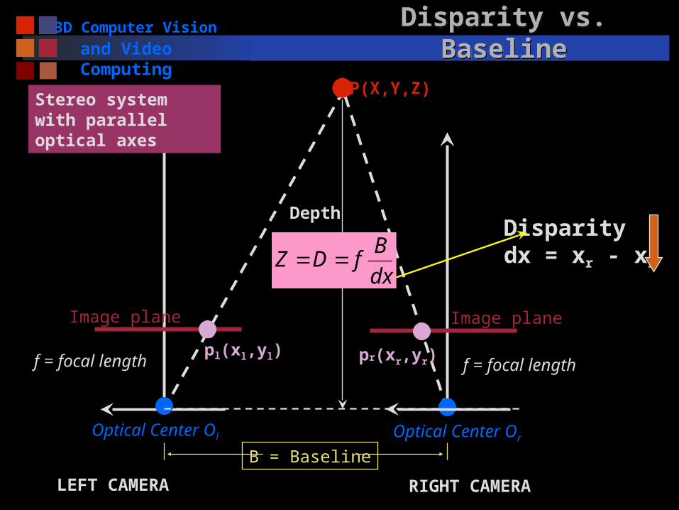
Stereo system with parallel optical axes
f = focal length
Optical Center Or
pr(xr,yr)
Image plane
RIGHT CAMERA
dx
BfDZ
Disparity: dx = xr - xl
3D Computer Vision
and Video Computing Disparity vs. BaselineDisparity vs. BaselineP(X,Y,Z)
pl(xl,yl)
Optical Center Ol
f = focal length
Image plane
LEFT CAMERA
B = Baseline
Depth
f = focal length
Optical Center Or
pr(xr,yr)
Image plane
RIGHT CAMERA
dx
BfDZ
Disparity dx = xr - xl
Stereo system with parallel optical axes
3D Computer Vision
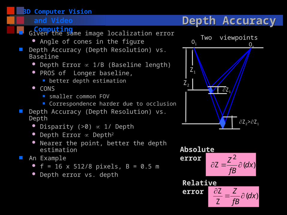
and Video Computing Depth AccuracyDepth Accuracy Given the same image localization error
Angle of cones in the figure Depth Accuracy (Depth Resolution) vs.
Baseline Depth Error 1/B (Baseline length) PROS of Longer baseline,
better depth estimation CONS
smaller common FOV Correspondence harder due to occlusion
Depth Accuracy (Depth Resolution) vs. Depth Disparity (>0) 1/ Depth Depth Error Depth2
Nearer the point, better the depth estimation
An Example f = 16 x 512/8 pixels, B = 0.5 m Depth error vs. depth
Z2
Two viewpoints
Z2>Z1
Z1
Z1
Ol Or
)(Z 2
dxfB
Z
)(Z
Z dx
fB
Z
Absolute error
Relative error
3D Computer Vision
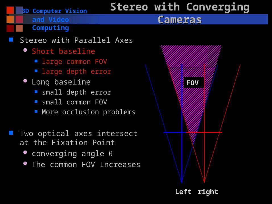
and Video ComputingStereo with Converging CamerasStereo with Converging Cameras
Stereo with Parallel Axes Short baseline
large common FOV large depth error
Long baseline small depth error small common FOV More occlusion problems
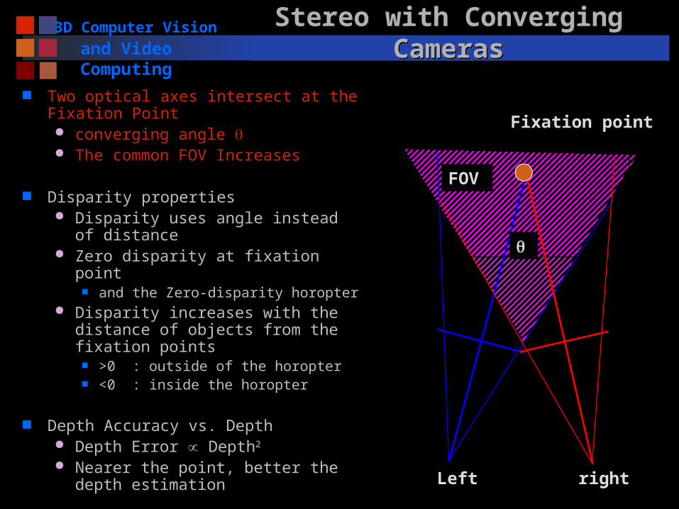
Two optical axes intersect at the Fixation Point converging angle The common FOV Increases
FOV
Left right
3D Computer Vision
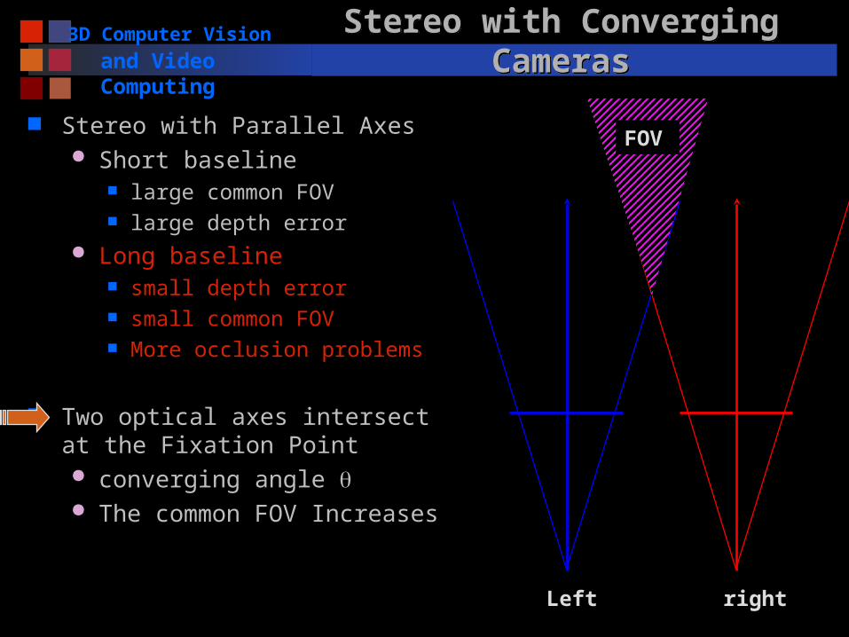
and Video ComputingStereo with Converging CamerasStereo with Converging Cameras
Stereo with Parallel Axes Short baseline
large common FOV large depth error
Long baseline small depth error small common FOV More occlusion problems
Two optical axes intersect at the Fixation Point converging angle The common FOV Increases
FOV
Left right
3D Computer Vision
and Video ComputingStereo with Converging CamerasStereo with Converging Cameras
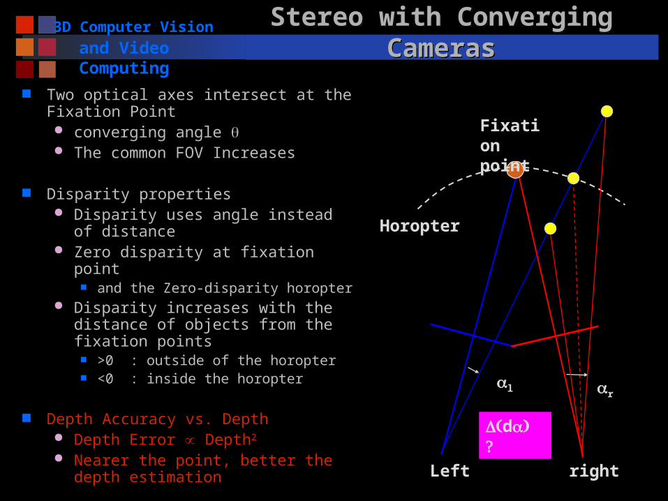
Two optical axes intersect at the Fixation Point converging angle The common FOV Increases
Disparity properties Disparity uses angle instead of
distance Zero disparity at fixation point
and the Zero-disparity horopter Disparity increases with the distance
of objects from the fixation points >0 : outside of the horopter <0 : inside the horopter
Depth Accuracy vs. Depth Depth Error Depth2
Nearer the point, better the depth estimation
FOV
Left right
Fixation point
3D Computer Vision
and Video Computing
Stereo with Converging CamerasStereo with Converging Cameras
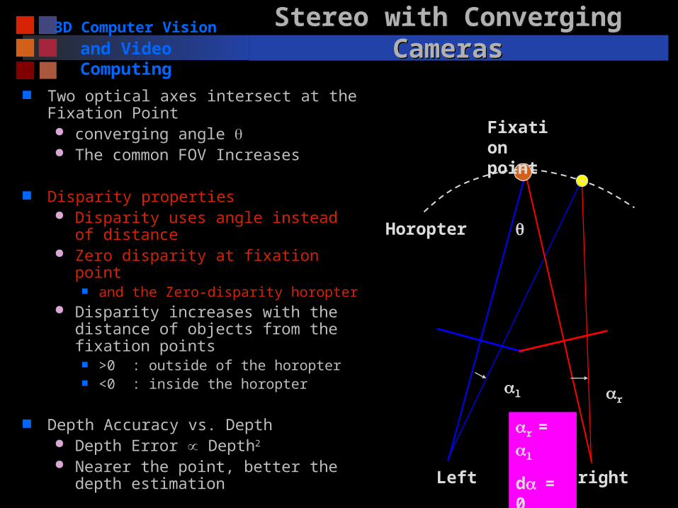
Two optical axes intersect at the Fixation Point converging angle The common FOV Increases
Disparity properties Disparity uses angle instead of
distance Zero disparity at fixation point
and the Zero-disparity horopter Disparity increases with the distance
of objects from the fixation points >0 : outside of the horopter <0 : inside the horopter
Depth Accuracy vs. Depth Depth Error Depth2
Nearer the point, better the depth estimation Left right
Fixation point
l r
r = l
d= 0
Horopter
3D Computer Vision
and Video Computing
Stereo with Converging CamerasStereo with Converging Cameras
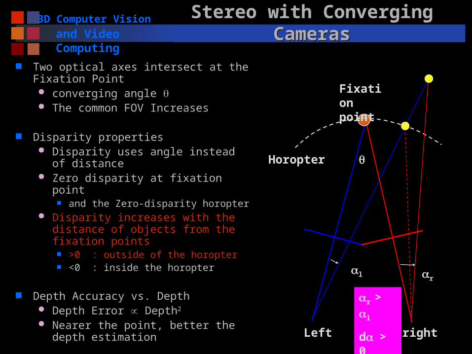
Two optical axes intersect at the Fixation Point converging angle The common FOV Increases
Disparity properties Disparity uses angle instead of
distance Zero disparity at fixation point
and the Zero-disparity horopter Disparity increases with the distance
of objects from the fixation points >0 : outside of the horopter <0 : inside the horopter
Depth Accuracy vs. Depth Depth Error Depth2
Nearer the point, better the depth estimation Left right
Fixation point
l r
r > l
d> 0
Horopter
3D Computer Vision
and Video ComputingStereo with Converging CamerasStereo with Converging Cameras
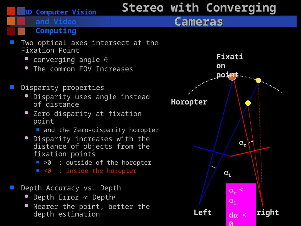
Two optical axes intersect at the Fixation Point converging angle The common FOV Increases
Disparity properties Disparity uses angle instead of
distance Zero disparity at fixation point
and the Zero-disparity horopter Disparity increases with the distance
of objects from the fixation points >0 : outside of the horopter <0 : inside the horopter
Depth Accuracy vs. Depth Depth Error Depth2
Nearer the point, better the depth estimation Left right
Fixation point
L
r
r < l
d< 0
Horopter
3D Computer Vision
and Video ComputingStereo with Converging CamerasStereo with Converging Cameras
Two optical axes intersect at the Fixation Point converging angle The common FOV Increases
Disparity properties Disparity uses angle instead of
distance Zero disparity at fixation point
and the Zero-disparity horopter Disparity increases with the distance
of objects from the fixation points >0 : outside of the horopter <0 : inside the horopter
Depth Accuracy vs. Depth Depth Error Depth2
Nearer the point, better the depth estimation Left right
Fixation point
l r
d
Horopter
3D Computer Vision
and Video Computing Parameters of a Stereo SystemParameters of a Stereo System
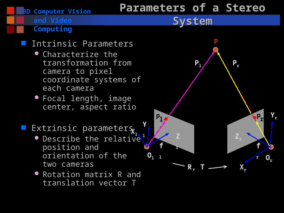
Intrinsic Parameters Characterize the
transformation from camera to pixel coordinate systems of each camera
Focal length, image center, aspect ratio
Extrinsic parameters Describe the relative
position and orientation of the two cameras
Rotation matrix R and translation vector T
pl
pr
P
Ol Or
Xl
Xr
Pl Pr
fl fr
Zl
Yl
Zr
Yr
R, T
3D Computer Vision
and Video Computing Epipolar GeometryEpipolar Geometry
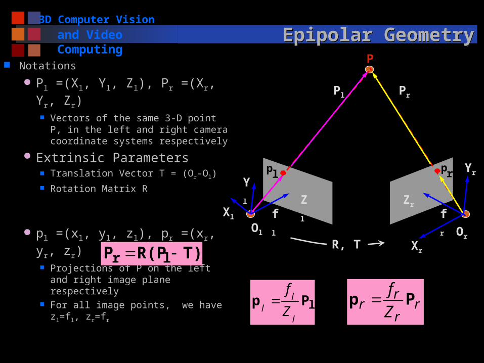
Notations
Pl =(Xl, Yl, Zl), Pr =(Xr, Yr, Zr) Vectors of the same 3-D point P,
in the left and right camera coordinate systems respectively
Extrinsic Parameters Translation Vector T = (Or-Ol) Rotation Matrix R
pl =(xl, yl, zl), pr =(xr, yr, zr) Projections of P on the left and
right image plane respectively For all image points, we have
zl=fl, zr=fr
T)R(PP lr
lPpl
ll Z
f r
r
rr Z
fPp
plpr
P
Ol Or
Xl
Xr
Pl Pr
fl fr
Zl
Yl
Zr
Yr
R, T
3D Computer Vision
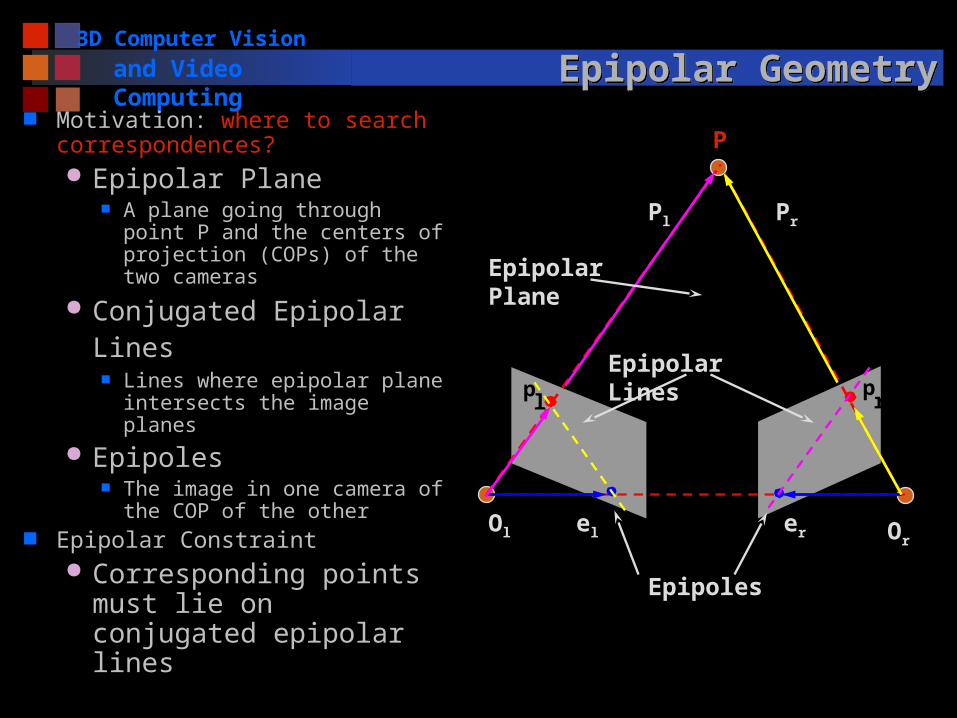
and Video Computing Epipolar GeometryEpipolar Geometry Motivation: where to search
correspondences? Epipolar Plane
A plane going through point P and the centers of projection (COPs) of the two cameras
Conjugated Epipolar Lines
Lines where epipolar plane intersects the image planes
Epipoles The image in one camera of
the COP of the other Epipolar Constraint
Corresponding points must lie on conjugated epipolar lines
pl
pr
P
Ol Orel er
Pl Pr
Epipolar Plane
Epipolar Lines
Epipoles
3D Computer Vision
and Video Computing Essential MatrixEssential Matrix
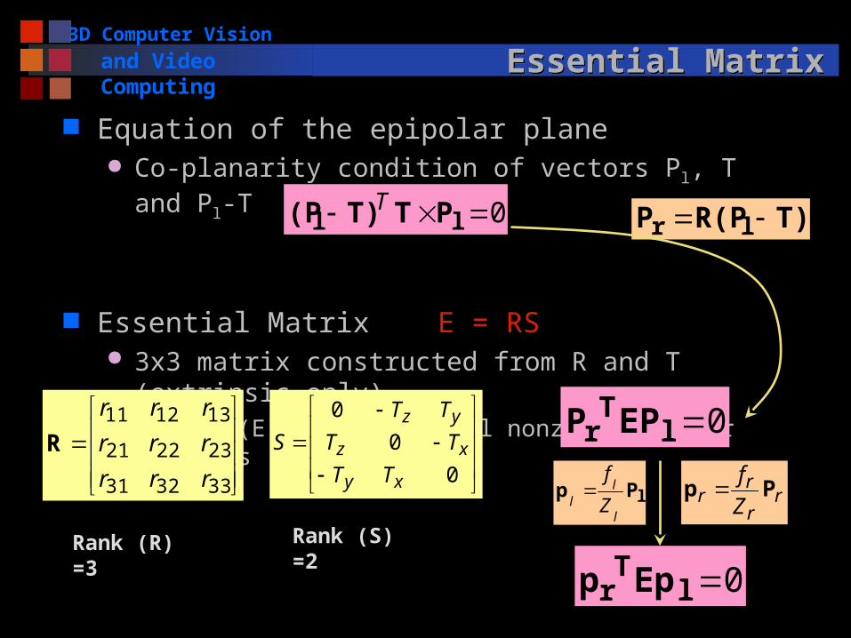
Equation of the epipolar plane Co-planarity condition of vectors Pl, T and Pl-T
Essential Matrix E = RS 3x3 matrix constructed from R and T (extrinsic only)
Rank (E) = 2, two equal nonzero singular values
0 ll PTT)(P T
0
0
0
xy
xz
yz
TT
TT
TT
S
333231
232221
131211
rrr
rrr
rrr
R
Rank (R) =3 Rank (S) =2
T)R(PP lr
0lTr EPP
0lTr Epp
lPpl
ll Z
f r
r
rr Z
fPp

3D Computer Vision
and Video Computing Essential MatrixEssential Matrix
Essential Matrix E = RS A natural link between the stereo point pair and the
extrinsic parameters of the stereo system One correspondence -> a linear equation of 9 entries Given 8 pairs of (pl, pr) -> E
Mapping between points and epipolar lines we are looking for
Given pl, E -> pr on the projective line in the right plane Equation represents the epipolar line of either pr (or pl) in
the right (or left) image
Note: pl, pr are in the camera coordinate system, not pixel
coordinates that we can measure
0lTr Epp
3D Computer Vision
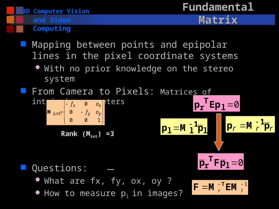
and Video Computing Fundamental MatrixFundamental Matrix
Mapping between points and epipolar lines in the pixel coordinate systems With no prior knowledge on the stereo system
From Camera to Pixels: Matrices of intrinsic parameters
Questions: What are fx, fy, ox, oy ? How to measure pl in images?
0lTr pFp
1 lr EMMF T
l1ll pMp rrr pMp 1
100
0
0
int yy
xx
of
of
M0l
Tr Epp
Rank (Mint) =3
3D Computer Vision
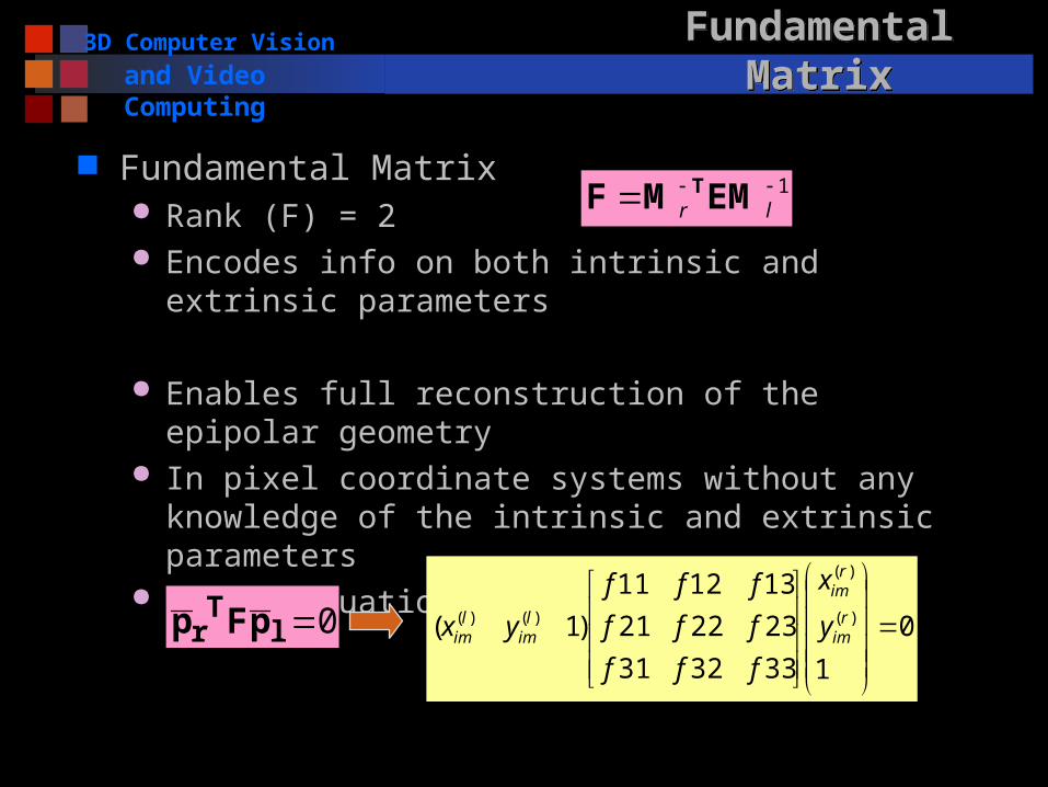
and Video Computing Fundamental MatrixFundamental Matrix
Fundamental Matrix Rank (F) = 2 Encodes info on both intrinsic and extrinsic parameters
Enables full reconstruction of the epipolar geometry In pixel coordinate systems without any knowledge of
the intrinsic and extrinsic parameters Linear equation of the 9 entries of F
0lTr pFp
1 lr EMMF T
0
1333231
232221
131211
)1( )(
)(
)()(
rim
rim
lim
lim y
x
fff
fff
fff
yx
3D Computer Vision
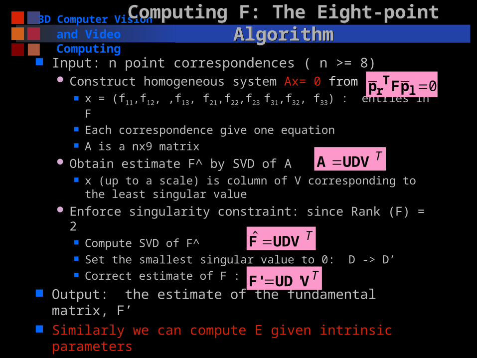
and Video ComputingComputing F: The Eight-point AlgorithmComputing F: The Eight-point Algorithm Input: n point correspondences ( n >= 8)
Construct homogeneous system Ax= 0 from x = (f11,f12, ,f13, f21,f22,f23 f31,f32, f33) : entries in F Each correspondence give one equation A is a nx9 matrix
Obtain estimate F^ by SVD of A x (up to a scale) is column of V corresponding to the least
singular value Enforce singularity constraint: since Rank (F) = 2
Compute SVD of F^ Set the smallest singular value to 0: D -> D’ Correct estimate of F :
Output: the estimate of the fundamental matrix, F’ Similarly we can compute E given intrinsic parameters
0lTr pFp
TUDVA
TUDVF ˆ
TVUDF' '
3D Computer Vision
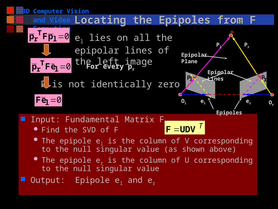
and Video ComputingLocating the Epipoles from FLocating the Epipoles from F
Input: Fundamental Matrix F Find the SVD of F The epipole el is the column of V corresponding to the
null singular value (as shown above) The epipole er is the column of U corresponding to the
null singular value Output: Epipole el and er
TUDVF
el lies on all the epipolar lines of the left image
0lTr pFp
0lTr eFp
F is not identically zero
For every pr
0leF
pl pr
P
Ol Orel er
Pl Pr
Epipolar Plane
Epipolar Lines
Epipoles
3D Computer Vision
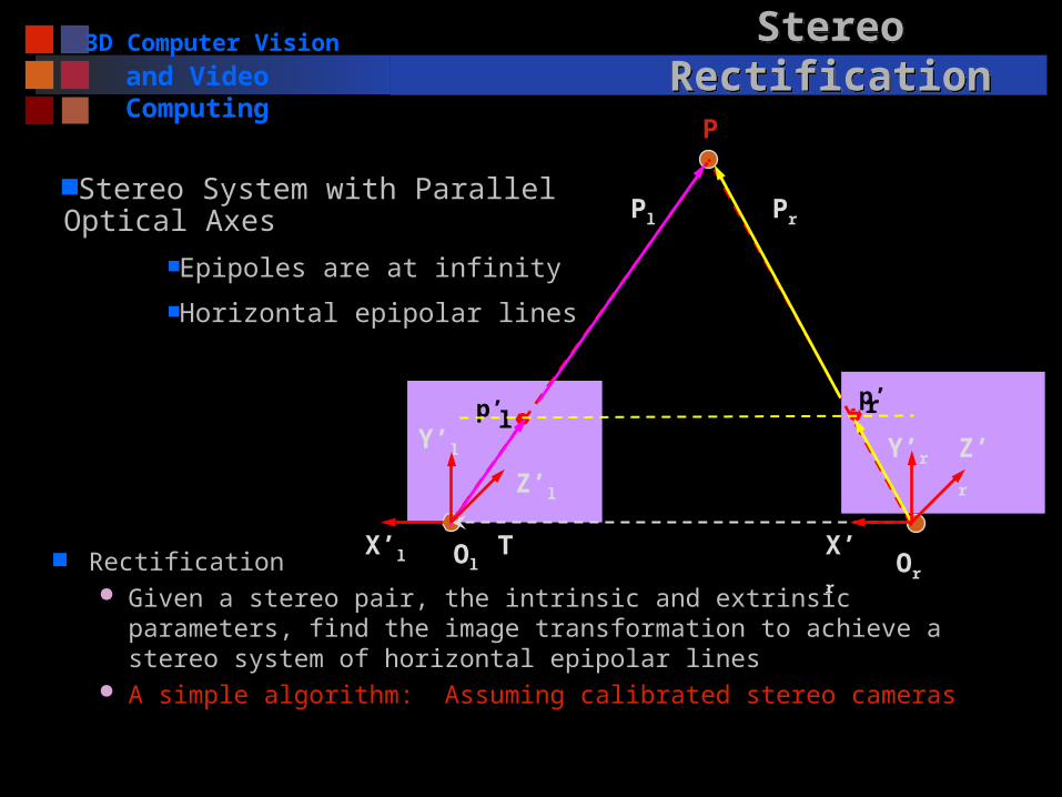
and Video Computing Stereo RectificationStereo Rectification
Rectification Given a stereo pair, the intrinsic and extrinsic parameters, find
the image transformation to achieve a stereo system of horizontal epipolar lines
A simple algorithm: Assuming calibrated stereo cameras
p’lp’r
P
Ol Or
X’r
Pl Pr
Z’l
Y’l Y’r
TX’l
Z’r
Stereo System with Parallel Optical AxesEpipoles are at infinity
Horizontal epipolar lines
3D Computer Vision
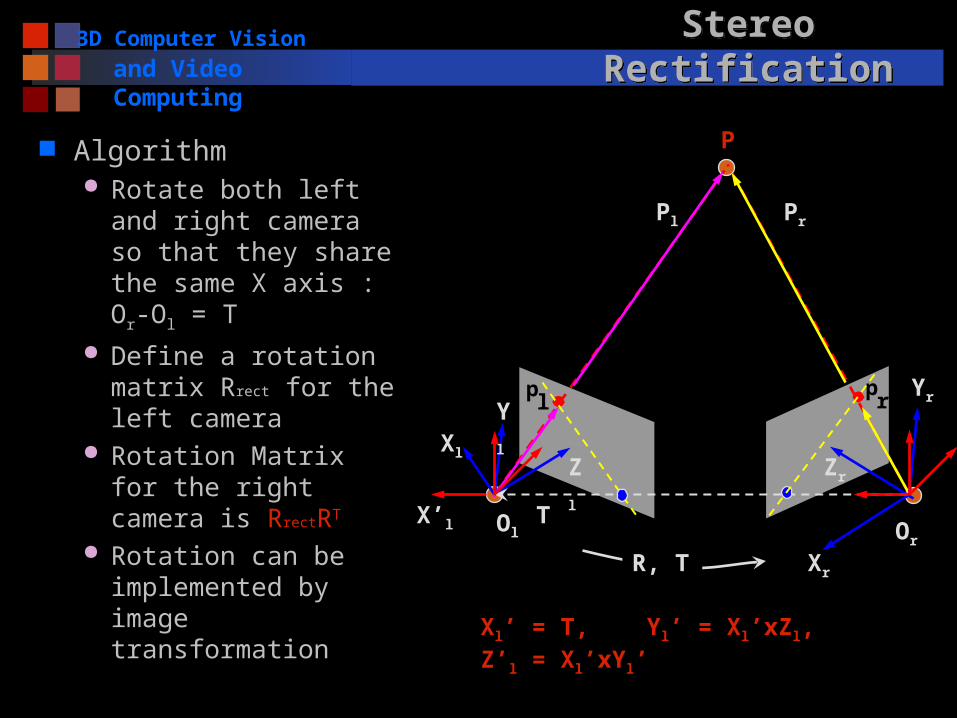
and Video Computing Stereo RectificationStereo Rectification
Algorithm Rotate both left and
right camera so that they share the same X axis : Or-Ol = T
Define a rotation matrix Rrect for the left camera
Rotation Matrix for the right camera is RrectRT
Rotation can be implemented by image transformation
pl
pr
P
Ol Or
Xl
Xr
Pl Pr
Zl
Yl
Zr
Yr
R, T
TX’l
Xl’ = T, Yl’ = Xl’xZl, Z’l = Xl’xYl’
3D Computer Vision
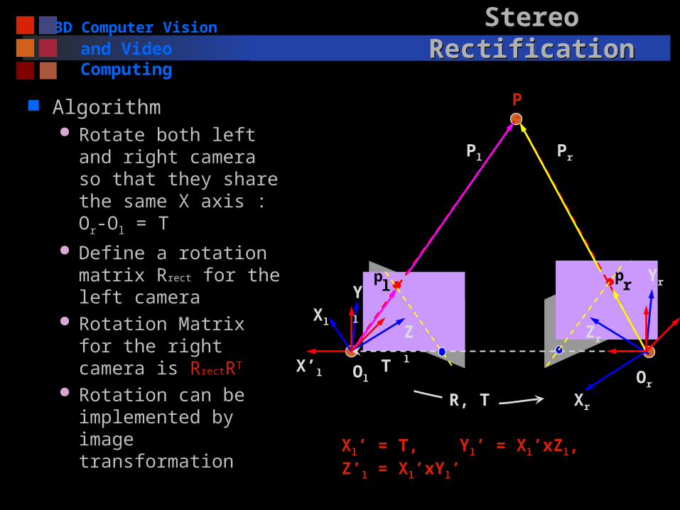
and Video Computing Stereo RectificationStereo Rectification
Algorithm Rotate both left and
right camera so that they share the same X axis : Or-Ol = T
Define a rotation matrix Rrect for the left camera
Rotation Matrix for the right camera is RrectRT
Rotation can be implemented by image transformation
pl
pr
P
Ol Or
Xl
Xr
Pl Pr
Zl
Yl
Zr
Yr
R, T
TX’l
Xl’ = T, Yl’ = Xl’xZl, Z’l = Xl’xYl’
3D Computer Vision
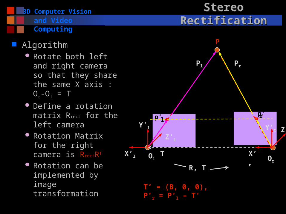
and Video Computing Stereo RectificationStereo Rectification
Algorithm Rotate both left and
right camera so that they share the same X axis : Or-Ol = T
Define a rotation matrix Rrect for the left camera
Rotation Matrix for the right camera is RrectRT
Rotation can be implemented by image transformation
Zr
p’lp’r
P
Ol Or
X’r
Pl Pr
Z’l
Y’l Y’r
R, T
TX’l
T’ = (B, 0, 0), P’r = P’l – T’
3D Computer Vision
and Video Computing NextNext
Two Primary Sub-problems in Stereo Vision Correspondence problem 3D reconstruction from stereo
Stereo Vision (II)