Embed Size (px)
Citation preview
3D Channel Model in 3GPP
Bishwarup Mondal, Timothy A. Thomas, Eugene Visotsky, Frederick W. Vook, Amitava Ghosh, Nokia Networks, USA
Young-Han Nam, Yang Li, Charlie Zhang, Samsung Research America
Min Zhang, Qinglin Luo, Alcatel-Lucent, Alcatel-Lucent Shanghai Bell
Yuichi Kakishima, Koshiro Kitao, NTT DOCOMO, INC.
Abstract — Multi-antenna techniques capable of exploiting the elevation dimension are anticipated
to be an important air-interface enhancement targeted to handle the expected growth in mobile traffic.
In order to enable the development and evaluation of such multi-antenna techniques, the 3rd
generation partnership project (3GPP) has recently developed a 3-dimensional (3D) channel model.
The existing 2-dimensional (2D) channel models do not capture the elevation channel characteristics
lending them insufficient for such studies. This article describes the main components of the newly
developed 3D channel model and the motivations behind introducing them. One key aspect is the
ability to model channels for users located on different floors of a building (at different heights). This
is achieved by capturing a user height dependency in modelling some channel characteristics
including pathloss, line-of-sight (LOS) probability, etc. In general this 3D channel model follows the
framework of WINNERII/WINNER+ while also extending the applicability and the accuracy of the
model by introducing some height and distance dependent elevation related parameters.
I. INTRODUCTION
It is predicted that the traffic carried by wireless and mobile communication systems will
increase around 1000-fold between 2010 and 2020. In addition there will be a proliferation of
the number of connected devices and the communication systems will experience a
coexistence of a diverse range of communication links ranging from very high data-rate
mobile multimedia services to low data-rate machine-to-machine type communication [1]. In
view of this, the International Telecommunications Union (ITU’s) working party 5D is
developing a recommendation on the framework and objectives of the future development of
International Mobile Telecommunications (IMT) for 2020 and beyond.

Multi-antenna transmission techniques using massive antenna configurations (such as more
than 8 transmit antenna ports) and exploiting 3D spatial dimensions (azimuth and elevation)
of a multiple-input multiple-output (MIMO) channel are critical in improving the spectral
efficiency and reliability of a radio-link. As a result of the significant interest shown in 3GPP
in supporting advanced MIMO transmission techniques exploiting both azimuth and
elevation dimensions of a wireless channel, a study was started in January 2013 targeting the
incorporation of a 3D channel model into the 3GPP evaluation methodology [2]. In this
article we describe the main elements of the finalized 3D channel model and also provide the
motivations for the various decisions made during the channel model development in 3GPP
RAN1 which may not be obvious and may not be documented in the official report [3].
So far, the evaluation and standardization of MIMO techniques in 3GPP has been primarily
based on 2D channel models from SCM, ITU and WINNERII [4][5][6]. These models
assume a 2D plane for the location of scatterers, reflectors and transmit/receive antennas, etc.
This 2D assumption limits the MIMO transmission techniques (beamforming, precoding,
spatial multiplexing, multi-user MIMO (MU-MIMO), etc.) to the azimuth dimension. In
order to evaluate techniques such as user equipment (UE, aka mobile) specific elevation
beamforming and full-dimension MIMO (FD-MIMO) [8], where the transmission is adapted
efficiently in both elevation and azimuth to a particular UE, or vertical sectorization where a
narrow elevation beam is tailored to each vertical sector, a 3D channel model is necessary.
The 3D channel model described here is a geometry-based stochastic (GSCM) model
(following the cluster-based approach common to COST-259, 273, 2100 as well as SCM,
WINNERII models) and naturally extends the 2D channel models from ITU/WINNERII. It is
also inspired by the extension from 2D to 3D channel model published as part of
WINNERII/WINNER+ [6][7].
This article is organized as follows: In Section II we describe the target environments and
the scope of the 3D channel model. Section I addresses the antenna model for a 2D polarized
antenna array that can be used for simulations using the 3D channel model. The subsequent
sections describe two key aspects of the 3D channel model – pathloss and LOS probability
considering UE locations in high floors (Section IV) and modelling of a multi-path
component in 3D (Section V). A summary of 3D channel model features from WINNERII,
WINNER+ and 3GPP is provided in Section VI.

II. APPLICABILITY OF THE 3D CHANNEL MODEL
The first step in the 3D channel modelling is to identify application environments. Urban
Macro (3D-UMa) and Urban Micro (3D-UMi) with enhanced node B’s (eNBs, aka base
stations) located outdoors are considered to be typical usage scenarios for elevation
beamforming and FD-MIMO. Using active antenna systems (AAS) in outdoor eNBs can
provide better services and user experience for indoor as well as outdoor UEs. The usage of
elevation beamforming and FD-MIMO for indoor eNBs (or distributed antenna systems –
DAS) was not prioritized due to the cost of AAS and the reduced scope of adaptability in the
elevation dimension in some indoor environments. The 3D-UMa and the 3D-UMi scenarios
follow the conventional 2D-UMa and the 2D-UMi scenarios as determined in ITU-R [5].
Both scenarios are considered to be densely populated by buildings and homogeneous in
nature – in terms of building height and building density. It may be assumed that the building
blocks (in 3D-UMa and 3D-UMi scenarios) form a regular Manhattan type grid or can have a
more irregular distribution while the building heights are typically distributed between 4 and
8 floors. In the case of 3D-UMa, it is assumed that the eNB height (25m) is well above the
heights of the surrounding buildings so that over the rooftop diffractions form the dominant
propagation mechanism for both indoor and outdoor UEs. In the case of 3D-UMi it is
assumed that the eNB height (10m) is well below the heights of the surrounding buildings
and therefore the received signal strength at the UE include contributions from both over the
rooftop and around building propagation mechanisms. Note that the building density,
building heights as well as the street layout described above were considered for both ray-
tracing simulations and field measurements in order to derive the 3D channel models
presented in this article.
The 3D channel model is applicable to UE heights ranging from 1.5m (street level) to
22.5m. A statistical approach for placing UEs is suggested for 3D-UMa and 3D-UMi that
does not require modelling building dimensions explicitly. An indoor UE can be associated
with a height given by hUE = 3(nfl – 1) + 1.5, where nfl is the floor number uniformly
distributed between 1 and Nfl. Nfl denotes the building height measured in floors and is
uniformly distributed between 4 and 8. Outdoor UEs can be assumed to be at 1.5m height.
This is a key aspect that extends the existing 3GPP [4] and ITU-R [5] methodologies where a
UE is always modelled at the street level.
The 3D channel model is applicable to carrier frequencies between 2-6 GHz with up to 100
MHz of bandwidth. Higher carrier frequencies, e.g., up to 300 GHz, are of interest in 5G
wireless communications and present a different set of challenges which are outside the scope
of this 3D channel model. It also assumes that the size of the antenna array is negligible
compared to the correlation distances of the large scale parameters such as shadow fading,
delay spread, angle spread and Rician factor. These assumptions follow the practices of other
existing channel models [5][6][7].
III. ANTENNA MODELLING
Now that simulation environments are described some specific details of the 3D channel
can be explained with a logical starting point being the eNB antennas themselves. A
conventional deployment of a multi-antenna array at a macro eNB may use one or more
cross-polarized antenna panels with +/-45 degree polarizations. Within each antenna panel
multiple antenna elements per polarization are arranged in the vertical dimension, e.g., 8
elements, to concentrate the transmission within a narrow beamwidth in the vertical
dimension (a half-power beamwidth on the order of 10 degrees). All of the antenna elements
in the panel are used for transmission and reception but only one (logical) antenna port has
been typically modelled along with a 2D channel model for system design and evaluation. As
an example, a 4-port cross-polarized multiple-antenna array has been modelled as a set of 2
pairs of antenna ports arranged in the azimuth dimension, each pair comprising of a +45 and
a -45 degree polarized co-located antenna ports. This arrangement provides an azimuth-only
logical representation of a 2D antenna array comprising of 32 antenna elements (4 elements
per row and 8 elements per column). Thus the study of MIMO techniques such as UE
specific beamforming, MU-MIMO, etc. was limited to spatial adaptation in the azimuth
dimension only.
The 3D channel model allows us to overcome this limitation and can be used for generating
channel responses to each of the 32 antenna elements in the 2D array. Towards this end, a
model for an individual antenna element is required for the 3D channel model.
Polarized antenna element modelling

In the interest of simplicity an antenna element at an eNB is characterized by an idealized
parabolic antenna pattern with 650 half-power beamwidth (in both azimuth and elevation)
with 8 dBi antenna element gain. Polarization can be simulated by two models – a constant
polarization model and a slanted dipole polarization model. A constant polarization model
assumes that the polarization power split is independent of UE location (i.e., UE azimuth and
elevation angles relative to broadside to the eNB array). A slanted dipole polarization model
is based on the idea that a polarization slant can be modelled as a mechanical tilt. Considering
a +45/-45 degree cross-polarized transmit antenna pair the constant polarization model
assumption leads to an equal power split in vertical and horizontal directions for all UE
locations. The slanted dipole polarization model achieves equal power split in vertical and
horizontal directions at the antenna boresight but the power split ratio depends on the UE
location in both azimuth and elevation dimensions. The choice of which polarization model
to use in a particular simulation would be based on the expected antenna patterns of the eNBs
being simulated. However it is worth noting that in detailed system simulations little
difference is seen in the performance between the two polarization models.
IV. LOS PROBABILITY AND PATHLOSS
With the basic antenna modelling done the next consideration before the fast fading
modelling is LOS/NLOS state and pathloss determination. In the existing 3GPP [4] or ITU
methodologies [5] the LOS probability model considers mainly street level UEs and the
dependency on UE height is not explicitly considered. The impact of varying UE heights
from 1.5m to 22.5m on LOS probability and pathloss modelling was studied for both 3D-
UMa and 3D-UMi scenarios.
It may be recognized that one approach of modelling LOS probability, pathloss as well as
fast-fading channel characteristics is to incorporate explicit building dimensions (a simplified
ray-tracing approach) in the model. In 3GPP, however, it was decided to retain the fully
stochastic approach of modelling as used in SCM [4] and in WINNER II [6] that does not
depend on building/street dimensions explicitly. This enables reusing partly the existing
modelling parameters from 2D stochastic models, helps incorporating measurement results
from multiple sources while also reducing the complexity and processing time for system-
level simulations. Also note that for UEs located indoors, the pathloss is simply determined

as a sum of an outdoor pathloss component, wall penetration loss and an indoor pathloss
component. Following this methodology, a LOS/NLOS state is associated to an indoor UE
which means that the LOS/NLOS state is actually applicable to the outdoor pathloss
component for that UE.
LOS Probability
The LOS probability for the 3D-UMa scenario is modelled as a sum of two probabilities -
type-1 and type-2 LOS probabilities [11]. The decomposition of the overall LOS probability
into type-1 and type-2 components is for modelling simplification. As shown in Figure 1(a) a
UE is considered to be in type-1 LOS state if a UE in the first floor of the same building is
also in a LOS state (UEs in the first floor can only be in type-1 LOS state). The type-1 LOS
probability depends only on the horizontal distance between the eNB and the UE and follows
the formula defined in the ITU model [5]. A LOS UE on a high floor of a building is
considered to be in type-2 LOS state if a UE on the first floor of the same building can never
achieve a LOS state. Note that the buildings are assumed to be at least 4-story high in 3D-
UMa and hence type-2 LOS cases occur only when the UE is located on a floor higher than a
4-story building i.e., 12 m. Beyond 12m the probability to be in type-2 LOS state
progressively increases with UE height and so is the overall LOS probability. The LOS
probability model, which is the sum of the type-1 and type-2 LOS probabilities, for 3D-UMa
as a function of UE height and distance is illustrated in Figure 3.
In a 3D-UMi scenario, where the eNB antenna is lower than the surrounding buildings type
1 and type 2 LOS states can be similarly defined as shown in Figure 1(b). However it was
found by ray-tracing simulations that the UE height is not likely to affect LOS probability in
the 3D-UMi scenario since type 2 LOS condition is limited to situations where the UE height
is significantly higher than that of the blocking buildings and hence it can rarely occur,
(mainly due to the low eNB height). Therefore the LOS probability model from ITU 2D-UMi
[5] is reused for 3D-UMi scenario.

Figure 1: Type 1 and type 2 LOS probabilities
Figure 2: Distance and height dependent LOS probability model for 3D-UMa
Pathloss Modelling (LOS)
In [12] it is shown that a height-dependent pathloss for an indoor UE associated with a
LOS state can be modelled considering the dimensions of the building and the location of the
UE inside the building. In 3GPP it was agreed to model LOS pathloss by using the 3D
distance between the eNB and the UE (d3D) along with the coefficients given by the ITU LOS
pathloss equations for both 3D-UMa and 3D-UMi. This provides a reasonable approximation
to the more accurate model in [12] and can be determined without modelling building
dimensions explicitly [13]. The ITU LOS pathloss model assumes a two-ray model resulting
in a pathloss equation transitioning from a 22dB/decade slope to a steeper slope at a
breakpoint depending on an environmental height. The environmental height represents the
0 100 200 300 400 500 600 700 800 900 10000
0.1
0.2
0.3
0.4
0.5
0.6
0.7
0.8
0.9
1
Distance(m)
LO
S p
robabili
ty
UE height(m)=1.5
UE height(m)=4.5
UE height(m)=7.5
UE height(m)=10.5
UE height(m)=13.5
UE height(m)=16.5
UE height(m)=19.5
UE height(m)=22.5
Type 1 LOS
NLOS
Type 2 LOS
Type 1 LOS
NLOS
Type 2 LOS
(a) 3D-UMa scenario (b) 3D-UMi scenario
height of a dominant reflection from the ground (or a car) that can add constructively or
destructively to the direct ray received at a UE located at the street level. In the 3D-UMa
scenario, it is likely that such a dominant reflection path may come from the street-level for
indoor UEs associated with a type-1 LOS condition. Therefore the environmental height is
fixed at 1m for a UE associated with a type-1 LOS condition. In the case of a UE associated
with a type-2 LOS condition, a dominant reflection can likely bounce of the rooftop of a
neighbouring building. Noting that a rooftop is at least 12m in height, in this case the
environmental height is randomly determined from a discrete uniform distribution of (12m,
15m,…, (h-1.5)m) where h is the UE height in meter.
Pathloss Modelling (NLOS)
For NLOS pathloss modelling, Figure 3(a) shows the primary radio propagation
mechanism in a 3D-UMa environment where the dominant propagation paths travel via
multiple-diffraction over rooftops followed by diffraction at the edge of a building. The
pathloss attenuation increases with the diffraction angle as a UE transitions from a high floor
to a low floor. In order to model this phenomenon a linear height gain term given by
(h1.5) is introduced, where (in dB/m) is the gain coefficient. A range of values
between 0.6 and 1.5 were observed in different results based on field measurements and ray
tracing simulations and eventually a value of 0.6 dB/m was agreed (see section 7.2.7.1 in [16]
for references). Figure 3(b) shows the principle of radio propagation for 3D-UMi
environment where the dominant propagation paths travel through and around buildings. The
UE may also receive small energy from propagation above rooftops. Considering simplicity
of modelling, a linear height gain is also applied to the 3D-UMi NLOS pathloss with a 0.3
dB/m gain coefficient based on the results from multiple sources. In addition, for both 3D-
UMa and 3D-UMi scenarios, the NLOS pathloss is lower-bounded by the corresponding LOS
pathloss because the pathloss in a NLOS environment is in principle larger than that in a LOS
environment.

Figure 3: Principle of the radio propagation for NLOS environment
V. FAST FADING MODEL
Now that antenna modelling, LOS probability and pathloss have been described fast
fading model can be readily presented in this section. In the following, a cellular downlink is
assumed for describing the fast fading model and hence the departure angles are defined at
the eNB side and the arrival angles are defined at the UE side. The fast fading channel
coefficients model the time-varying fluctuations of wireless channels that are caused by the
combination of multipath and UE movement. The channel coefficients of a link between a
transmitter and a receiver are determined by the composite channel impulse responses of the
multiple path components (MPCs). Each MPC is characterized by a path delay, a path power
and random phases introduced during the propagation as well as the incident path angles, i.e.,
azimuth angles of departure and arrival (AOD and AOA) and zenith angles of departure and
arrival (ZOD and ZOA).
Diffraction angle
(a) 3D-UMa scenario (b) 3D-UMi scenario

Step 1: Set scenario, network layout and antenna parameters
Step 9: Generate XPRsStep 8: Perform
random coupling of rays
Step 7: Generate arrival & departure
angles
Step 6: Generate cluster powers
Step 5: Generate delays
Step 2: Assign propagation
condition (NLOS/LOS, indoor/outdoor)
Step 3: Calculate pathloss
Step 4: Generate correlated large scale parameters (DS, AS,
SF, K)
Step 10: Draw random initial phases
Step 11: Generate channel coefficient
Step 12: Apply pathloss and shadowing
Large Scale parameters
Small scale parameters:
Coefficient generation:
Block changed in 3D channel model
(a) Channel generation steps in the 3GPP 3D channel model [3]
LOS ZoD
Diffraction
ZoD mean
(b) ZOD in outdoor LOS and NLOS conditions
Outdoor LOS UEs Outdoor NLOS UEs
DiffractionPenetration
Reflection
(c) ZOA in indoor and outdoor NLOS conditions
ZoD offset
900
ZOD
ZOA
Figure 4: Fast-fading channel generation steps and propagation mechanisms
Figure 4(a) shows the steps to generate fast fading channel coefficients in the 3GPP 3D
channel model. The high-level procedure shown in Figure 4(a) is the same as its precedent
2D channel model in TR 36.814 [9] but a few steps have been revised to take into account the

channel characteristics in the elevation domain. As explained in Section IV a LOS or NLOS
state associated to a UE is jointly determined in step 2 by both UE horizontal distance and
UE height. The pathloss in step 3 is determined based upon a LOS probability and a height-
gain term depending on the UE height and distance from the eNB. In step 4 and step 7 zenith
angle spreads at departure and at arrival (ZSD and ZSA) and ZOD and ZOA are generated in
addition to the azimuth spread values and angles ASD, ASA, AOD and AOA. In step 8, for
each path, the AOA sub-paths are randomly coupled with the AOD sub-paths, the ZOA sub-
paths and the ZOD sub-paths. Finally, in step 11, the channel generation equation is modified
to take into account ZOAs and ZODs. The rest of this section explains in more detail the
newly-introduced elevation parameters and procedures in these revised steps in the 3GPP 3D
channel models.
Power angular spectrum in zenith (PAS-Z)
Measurement results and ray tracing data have indicated that the marginal distribution of
the composite power angular spectrum in zenith (PAS-Z) is Laplacian, and its conditional
distribution given a certain link distance and UE height can also be approximated by
Laplacian [14][15]. To incorporate these observations ZOD and ZOA are modeled by inverse
Laplacian functions.
Composite ZSD
It is also observed that the ZSD decreases significantly as a UE moves further away from
the eNB [14]. An intuitive explanation is provided by the fact that the angle subtended by a
fixed local ring of scatterers at the UE to the eNB decreases as the UE moves away from the
eNB. The ZSD is also observed to change to a smaller extent as an indoor UE moves up to
higher floors [14][15]. The ZSD model incorporated in 3GPP is a function of UE height and
distance from the eNB as shown in Figure 5.1 and Figure 5.2. Applying these ZSD models to
3D-UMa with 500m inter site distance (ISD) and 3D-UMi with 200m ISD described in
Section II with UE height distributed between 1.5 and 22.5m we can observe the overall
distribution of ZSD in a wireless network deployment. In Figure 5.5 we show the empirical
probability density of ZSD for the serving cell links as observed in the 3D-UMa and 3D-UMi
scenarios. Note that the ZSD tends to be a little smaller in the case of 3D-UMa reflecting a
clear dominance of above roof-top propagation mechanism.
ZOD offset
Note that in the azimuth dimension the AODs (corresponding to different MPCs) for a
given link are centered at the azimuth LOS angle between the UE and the eNB. In the
elevation dimension, however, the ZODs are not centered at the LOS zenith angle for NLOS
cases. This can be observed from Figure 4(b) NLOS case where it is shown that the mean
ZOD is shifted from the LOS ZOD because the bulk of the energy is received via diffraction
from the building edges (rooftops) blocking the direct path between the UE and the eNB. The
magnitude of the ZOD offset becomes smaller as the distance of the link increases partly
because the angle subtended by a given building to an eNB decreases with distance. It is also
clear from Figure 4(b) NLOS case that the ZOD offset decreases with an increase in UE
height. These observations were captured in the ZOD offset model shown in Figure 5.3 and
5.4. In the case of 3D-UMi the dependence of ZOD offset on UE height was not modeled
because the results showed some variation across different sources (see Table 7.3-8 in [3] for
references). On the other hand, it may be noted that when an indoor UE is associated with a
LOS state (denoted as LOS outdoor to indoor, or LOS O-to-I), the effect of diffraction paths
does not dominate and hence the ZOD offset is modeled to be zero. The application of the
ZOD offset models from Figure 5.3 and 5.4 to the 3D-UMa and 3D-UMi scenarios with UE
height ranging from 1.5 to 22.5m results in mean ZOD distributions as shown in Figure 5.6. It
may be noted that for 3D-UMi the eNB height is below the surrounding buildings leading to
mean ZOD distributed on both sides of the horizon (90 degrees) while for 3D-UMa the eNB
height is above the surrounding buildings leading to mean ZOD distributed on only one side
of the horizon.
The ZOAs (corresponding to different MPCs) for UEs located indoors is modeled to be centered
at 90 degrees. This is justified especially when the UE is deep inside the building where the indoor
paths are guided by the floor and the ceiling as Figure 4 (c) illustrates. The ZOA center angle for
outdoor UEs is modeled as the LOS ZOD angle for simplicity.
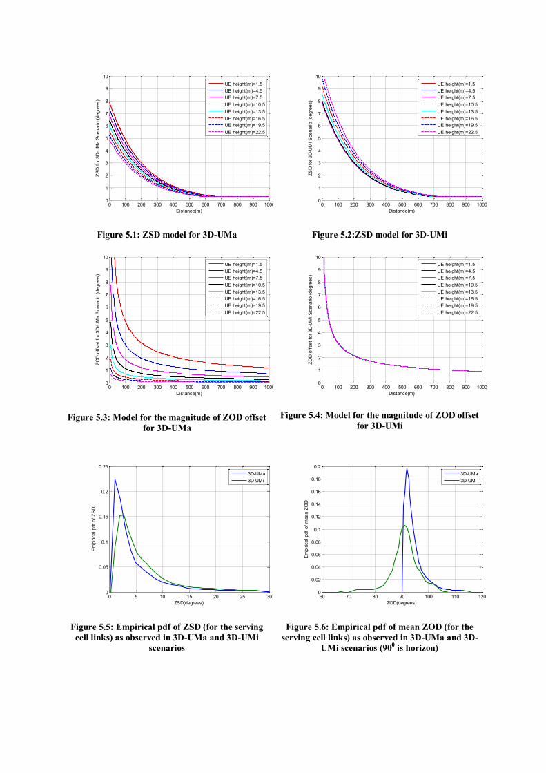
Figure 5.1: ZSD model for 3D-UMa
Figure 5.2:ZSD model for 3D-UMi
Figure 5.3: Model for the magnitude of ZOD offset
for 3D-UMa
Figure 5.4: Model for the magnitude of ZOD offset
for 3D-UMi
Figure 5.5: Empirical pdf of ZSD (for the serving
cell links) as observed in 3D-UMa and 3D-UMi
scenarios
Figure 5.6: Empirical pdf of mean ZOD (for the
serving cell links) as observed in 3D-UMa and 3D-
UMi scenarios (900 is horizon)
0 100 200 300 400 500 600 700 800 900 10000
1
2
3
4
5
6
7
8
9
10
Distance(m)
ZS
D f
or
3D
-UM
a S
cenario (
degre
es)
UE height(m)=1.5
UE height(m)=4.5
UE height(m)=7.5
UE height(m)=10.5
UE height(m)=13.5
UE height(m)=16.5
UE height(m)=19.5
UE height(m)=22.5
0 100 200 300 400 500 600 700 800 900 10000
1
2
3
4
5
6
7
8
9
10
Distance(m)
ZS
D f
or
3D
-UM
i S
cenario (
degre
es)
UE height(m)=1.5
UE height(m)=4.5
UE height(m)=7.5
UE height(m)=10.5
UE height(m)=13.5
UE height(m)=16.5
UE height(m)=19.5
UE height(m)=22.5
0 100 200 300 400 500 600 700 800 900 10000
1
2
3
4
5
6
7
8
9
10
Distance(m)
ZO
D o
ffset
for
3D
-UM
a S
cenario (
degre
es)
UE height(m)=1.5
UE height(m)=4.5
UE height(m)=7.5
UE height(m)=10.5
UE height(m)=13.5
UE height(m)=16.5
UE height(m)=19.5
UE height(m)=22.5
0 100 200 300 400 500 600 700 800 900 10000
1
2
3
4
5
6
7
8
9
10
Distance(m)
ZO
D o
ffset
for
3D
-UM
i S
cenario (
degre
es)
UE height(m)=1.5
UE height(m)=4.5
UE height(m)=7.5
UE height(m)=10.5
UE height(m)=13.5
UE height(m)=16.5
UE height(m)=19.5
UE height(m)=22.5
0 5 10 15 20 25 300
0.05
0.1
0.15
0.2
0.25
ZSD(degrees)
Em
piric
al pdf
of
ZS
D
3D-UMa
3D-UMi
60 70 80 90 100 110 1200
0.02
0.04
0.06
0.08
0.1
0.12
0.14
0.16
0.18
0.2
ZOD(degrees)
Em
piric
al pdf
of
mean Z
OD
3D-UMa
3D-UMi

Fast fading channel generation equation
After characterizing all azimuth and zenith angles of MPCs and related parameters, the
channel of the n-th path between u-th UE antenna and s-th eNB antenna is given by:
tvjdrjdrjF
F
jj
jj
F
FMPtH
mnstx
T
mntx
T
mnrx
AODmnZODmnstx
AODmnZODmnstx
mnmnmn
mnmnmn
TM
m AOAmnZOAmnurx
AOAmnZOAmnurx
nnsu
urx ,,,,
1
0,,
1
0
,,,,,,
,,,,,,
,,
1
,
,
1
,,
1 ,,,,,,
,,,,,,
,,
2exp.ˆ2exp.ˆ2exp,
,
expexp
expexp
,
,)(
,
Here, Frx,u,θ and Frx,u,ϕ are field patterns of the receive antenna element u in the direction
of the spherical basis vectors, a zenith basis vector ̂ and an azimuth basis vector ̂ ,
respectively. Ftx,s,θ and Ftx,s,ϕ are field patterns of the transmit antenna element s in the
direction of ̂ and ̂ , respectively. The 2x2 matrix between the arrival and departure field
pattern vectors is the depolarization matrix, of which two diagonal elements characterise the
co-polarized phase response, and the two off-diagonal elements model the cross-polarized
phase response and power attenuation1
,
mn . If polarisation is not considered, the 2x2
polarisation matrix can be replaced by the scalar mnj ,exp and only vertically polarised field
patterns are applied. mnrxr ,,
ˆ is the spherical unit vector with azimuth arrival angle ϕn,m,AOA and
zenith arrival angle θn,m,ZOA, given by:
ZOAmn
AOAmnZOAmn
AOAmnZOAmn
mnrxr
,,
,,,,
,,,,
,,
cos
sinsin
cossin
ˆ
;
and mntxr ,,
ˆ is the spherical unit vector with azimuth departure angle ϕn,m,AOD and elevation
departure angle θn,m,ZOD, given by
ZODmn
AODmnZODmn
AODmnZODmn
mntxr
,,
,,,,
,,,,
,,
cos
sinsin
cossin
ˆ
.
and are respectively the location vectors of receive antenna element u and
transmit antenna element s. 0 is the wavelength of the carrier frequency.
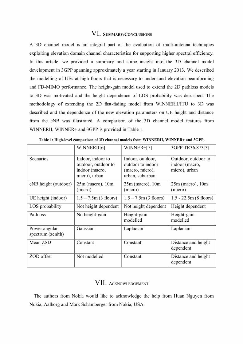
VI. SUMMARY/CONCLUSIONS
A 3D channel model is an integral part of the evaluation of multi-antenna techniques
exploiting elevation domain channel characteristics for supporting higher spectral efficiency.
In this article, we provided a summary and some insight into the 3D channel model
development in 3GPP spanning approximately a year starting in January 2013. We described
the modelling of UEs at high-floors that is necessary to understand elevation beamforming
and FD-MIMO performance. The height-gain model used to extend the 2D pathloss models
to 3D was motivated and the height dependence of LOS probability was described. The
methodology of extending the 2D fast-fading model from WINNERII/ITU to 3D was
described and the dependence of the new elevation parameters on UE height and distance
from the eNB was illustrated. A comparison of the 3D channel model features from
WINNERII, WINNER+ and 3GPP is provided in Table 1.
Table 1: High-level comparison of 3D channel models from WINNERII, WINNER+ and 3GPP.
WINNERII[6] WINNER+[7] 3GPP TR36.873[3]
Scenarios Indoor, indoor to
outdoor, outdoor to
indoor (macro,
micro), urban
Indoor, outdoor,
outdoor to indoor
(macro, micro),
urban, suburban
Outdoor, outdoor to
indoor (macro,
micro), urban
eNB height (outdoor) 25m (macro), 10m
(micro)
25m (macro), 10m
(micro)
25m (macro), 10m
(micro)
UE height (indoor) 1.5 – 7.5m (3 floors) 1.5 – 7.5m (3 floors) 1.5 - 22.5m (8 floors)
LOS probability Not height dependent Not height dependent Height dependent
Pathloss No height-gain Height-gain
modelled
Height-gain
modelled
Power angular
spectrum (zenith)
Gaussian Laplacian Laplacian
Mean ZSD Constant Constant Distance and height
dependent
ZOD offset Not modelled Constant Distance and height
dependent
VII. ACKNOWLEDGEMENT
The authors from Nokia would like to acknowledge the help from Huan Nguyen from
Nokia, Aalborg and Mark Schamberger from Nokia, USA.

REFERENCES
[1] A. Osseiran et al, “The foundation of the Mobile and Wireless Communications System for 2020 and
beyond Challenges, Enablers and Technology Solutions”, VTC Spring 2013, June 2-5, 2013.
[2] 3GPP RP-122034: "Study on 3D-channel model for Elevation Beamforming and FD-MIMO studies for
LTE", RAN#58, Dec. 2012.
[3] 3GPP TR 36.873 V2.0.0, "Study on 3D channel model for LTE", Mar. 2014.
[4] 3GPP TR 25.996 V11.0.0, “Spatial channel model for MIMO simulations”, Sept. 2012.
[5] ITU-R M.2135-1, “Guidelines for Evaluation of Radio Interface Technologies for IMT-Advanced,” Dec. 2009.
[6] WINNER II Channel Models, Deliverable D1.1.2 V1.2, IST-4-027756 WINNER II Deliverable, 4 Feb.
2008.
[7] WINNER+ Final Channel Models, Deliverable D5.3 V1.0, 30 Jun. 2010.
[8] Y.-H. Nam, B. L. Ng, K. Sayana, Y. Li, J. Zhang, Y. Kim and J. Lee, “Full-dimension MIMO (FD-MIMO)
for next generation cellular technology,” IEEE Communications Magazine, Vol. 51, Issue 6, Jun.
2013.
[9] 3GPP TR 36.814 V9.0.0, “Further Advancements for E-UTRA Physical layer Aspects”, Mar. 2010.
[10] 3GPP TR 37.840 V12.1.0, “Study of Radio Frequency (RF) and Electromagnetic Compatibility (EMC)
requirements for Active Antenna Array System (AAS) base station”, Dec. 2013.
[11] 3GPP R1-133273, “Height Dependent LOS Probability for 3D-Channel Model”, Ericsson, ST-Ericsson,
RAN1#74, Aug. 2013. [12] COST 231 “Digital mobile radio towards future generation systems, COST 231 - Final report (chapter
4.6.2)," European Commission, no. EUR 18957, 1999.
[13] 3GPP R1-131248, “Path Loss Modeling for UE-Specific Elevation Beamforming and FD-MIMO”, NSN,
Nokia, RAN1#72bis, Chicago, Apr. 2013.
[14] 3GPP R1-134813, “Remaining details of fast fading modeling for 3D-UMa and 3D-UMi”, NSN, Nokia,
RAN1#74bis, Oct. 2013.
[15] 3GPP R1-134221, “Proposals for Fast Fading Channel Modelling for 3D UMa”, Alcatel-Lucent Shanghai
Bell, Alcatel-Lucent, China Unicom, RAN1#74bis, Oct. 2013.
[16] 3GPP R1-134036, “Final report of 3GPP TSG RAN WG1 #74 v1.0.0”, RAN1#74bis, Oct. 2013.
Note – 3GPP documents may be downloaded from ftp://ftp.3gpp.org. WINNER II, WINNER+ documents may be downloaded from
http://projects.celtic-initiative.org/winner+/index.html.
ABBREVIATIONS
The following abbreviations are used in this article:
3D-UMa: 3-Dimensional Urban-Macro scenario
3D-UMi: 3-Dimensional Urban-Micro scenario
3GPP: Third Generation Partnership Project
AAS: Advanced Antenna System
AOA: Azimuth Angle of Arrival
AOD: Azimuth Angle of Departure
ASA: Azimuth Angular Spread at Arrival
ASD: Azimuth Angular Spread at Departure
COST: European Cooperation in Science and Technology
DAS: Distributed Antenna System
eNB: enhanced Node B aka base-station
FD-MIMO: Full Dimension Multiple Input Multiple Output
GSCM: Geometry based Stochastic Channel Model
IMT: International Mobile Telecommunications

ISD: Inter-Site Distance
ITU: International Telecommunication Union
ITU-R: International Telecommunication Union - Radio communication sector
LOS: Line-of-Sight
MIMO: Multiple Input Multiple Output
MPC: Multi-Path Component
MU-MIMO: Multi-User MIMO
NLOS: Non Line-of-Sight
PAS-Z: Power Angular Spectrum in Zenith
RAN1: Radio Access Network Working Group for Radio Layer 1
SCM: 3GPP Spatial Channel Model
UE: User Equipment
WINNER: Wireless Word Initiative New Radio
ZOA: Zenith Angle of Arrival
ZOD: Zenith Angle of Departure
ZSA: Zenith Angular Spread at Arrival
ZSD: Zenith Angular Spread at Departure
BIOGRAPHIES
Bishwarup Mondal received the B.E. and M.E. degrees from Jadavpur University and the Indian Institute of
Science in 1997 and 2000 respectively and the Ph.D. degree from the University of Texas at Austin in 2006. He
is presently with Nokia, Arlington Heights, IL. He is the recipient of the 2005 IEEE Vehicular Technology Society Daniel E. Noble Fellowship and a co-author of the best student paper award in IEEE Globecom 2006.
Eugene Visotsky received a B.S., an M.S. and a Ph.D. in Electrical Engineering in 1996, 1998, and 2000,
respectively, from University of Illinois at Urbana-Champaign. He is currently with Nokia, Arlington Heights,
IL. His current areas of interest are in advanced inter-cell interference coordination, cooperative transmission
algorithms and 3D MIMO techniques.
Frederick W. Vook (SM'04) received the B.S. degree from Syracuse University in 1987 and the M.S. and Ph.D.
degrees from The Ohio State University in 1989 and 1992, respectively, all in electrical engineering. From 1992
to 2011, he was with Motorola, Schaumburg, IL. Since 2011, he has been with Nokia, Arlington Heights, IL,
where his current work involves advanced antenna array solutions for LTE and 5G cellular systems.
Timothy A. Thomas received the B.S. degree from the University of Illinois at Urbana-Champaign in 1989; the
M.S. degree from the University of Michigan, in 1990; and the Ph.D. degree from Purdue University in 1997.
From 1997 to 2011, he was with Motorola, Schaumburg, IL, and since 2011, he has been with the North
American Radio Systems Research Group, Technology and Innovation Office, Nokia, Arlington Heights, IL.
Amitabha (Amitava) Ghosh joined Motorola in 1990 after receiving his Ph.D in Electrical Engineering from
Southern Methodist University, Dallas. Since joining Motorola he worked on multiple wireless technologies
starting from IS-95, cdma-2000, 1xEV-DV/1XTREME, 1xEV-DO, UMTS, HSPA, 802.16e/WiMAX/802.16m,
Enhanced EDGE and 3GPP LTE. Dr. Ghosh has 60 issued patents and numerous external and internal technical
papers. Currently, he is Head, North America Radio Systems Research within the Technology and Innovation
office of Nokia Networks. He is currently working on 3GPP LTE-Advanced and 5G technologies. His research interests are in the area of digital communications, signal processing and wireless communications. He is a
senior member of IEEE and co-author of the book titled “Essentials of LTE and LTE-A”.
YOUNG-HAN NAM received his B.S. and M.S from Seoul National University, Korea, in 1998 and 2002,
respectively. He received a Ph.D. in electrical engineering from the Ohio State University, Columbus, in 2008.
Since February 2008 he has been working at Samsung Research America at Dallas, Richardson, Texas. He has
been engaged in standardization, design and analysis of the 3GPP LTE and LTE-Advanced from Release 8
through 12. His research interests include MIMO/multi-user/cooperative wireless communications, cross-layer
design, and information theory.

Yang Li is a Senior Research Engineer in Samsung Research America, Dallas. He received a B.S. and a M.S.
degree, in 2005 and 2008, in electronic engineering from Shanghai Jiao Tong University, Shanghai, China, and
a Ph.D. degree in 2012, in electrical engineering from The University of Texas at Dallas, Richardson, TX, USA.
His research interests include MIMO, interference management, cooperative communication and cognitive
radio.
Jianzhong (Charlie) Zhang [S’96, M’02, SM’09]: Jianzhong(Charlie) Zhang is currently senior director and
head of Wireless Communications Lab with Samsung Research America at Dallas, where he leads technology
development, prototyping and standardization for Beyond 4G and 5G wireless systems. From Aug 2009 to Aug
2013, he served as the Vice Chairman of the 3GPP RAN1 working group and led development of LTE and
LTE-Advanced technologies such as 3D channel modeling, UL-MIMO and CoMP, Carrier Aggregation for TD-
LTE, etc. Before joining Samsung, he was with Motorola from 2006 to 2007 working on 3GPP HSPA standards, and with Nokia Research Center from 2001 to 2006 working on IEEE 802.16e (WiMAX) standard and
EDGE/CDMA receiver algorithms. He received his Ph.D. degree from University of Wisconsin, Madison.
Min Zhang received his M.S. degree with Distinction in Telecommunication from University of Canterbury,
New Zealand in 2005, and Ph.D. degree from Australian National University in Telecommunication in 2009. He
worked for Alcatel-Lucent since 2009 as wireless researcher and senior standards engineer, where he is
currently working on 3GPP LTE/LTE-A standardisation. His interests include wireless channel modelling,
communication and information theory, MIMO-OFDM system design, and performance optimization of
standards.
Qinglin Luo is a leading research scientist with Bell Labs Shanghai. His primary responsibilities include
conducting and leading research projects on air-interface technologies for next generation communications. In previous postings, he has been with Motorola, UK as a base station system architect, and with China Academy
of Telecommunication Technologies (CATT), as a standard engineer. He holds a Ph.D. degree in electrical
engineering from University of Surrey, UK. His current research interests include advanced antenna array
techniques, massive MIMO, error control coding, wireless cloud, etc.
Yuichi Kakishima received the B.S. and M.S. degrees from Tokyo Institute of Technology, Tokyo, Japan, in
2005 and 2007, respectively. In 2007, he joined NTT DOCOMO, INC. Since joining NTT DOCOMO, he has
been engaged in the research and development of wireless access technologies including multiple-antenna
transmission techniques for LTE and LTE-Advanced systems.
Koshiro Kitao was born in Tottori, Japan, in 1971. He received B.S., M.S. and Ph. D. degrees from Tottori
University, Tottori, Japan in 1994, 1996 and 2009 respectively. He joined the Wireless Systems Laboratories, Nippon Telegraph and Telephone Corporation (NTT), Kanagawa, Japan, in 1996. Since then, he has been
engaged in the research of radio propagation for mobile communications. He is now Research Engineer of the
Research Laboratories, NTT DOCOMO, INC., Kanagawa, Japan.

![A General 3-D Non-Stationary 5G Wireless Channel Modelhome.eps.hw.ac.uk/~cw46/2018_WuS_TCOM_18_07_3065.pdf · Based on the 3GPP NR channel model, the IMT-2020 channel model [22] was](https://img.pdfslide.us/doc/110x75/5ecb268558011c7b580e0a2e/a-general-3-d-non-stationary-5g-wireless-channel-cw462018wustcom18073065pdf.jpg)
![TS 136 211 - V8.7.0 - LTE; Evolved Universal Terrestrial Radio … · 6.5 Physical multicast channel .....57 6.6 Physical broadcast channel ... [5] 3GPP TS 36.214: "Evolved Universal](https://img.pdfslide.us/doc/110x75/5af57abc7f8b9a9e598e19f9/ts-136-211-v870-lte-evolved-universal-terrestrial-radio-physical-multicast.jpg)


![Scalable and accurate channel models for analysis …[3GPP] 3GPP, “Study on channel model for frequency spectrum above 6 GHz (Release 14) “, TR 38.900 V14.2.0, Dec. 2016. [NYU]](https://img.pdfslide.us/doc/110x75/5f3c691e9cce091fc171c655/scalable-and-accurate-channel-models-for-analysis-3gpp-3gpp-aoestudy-on-channel.jpg)