Embed Size (px)
Citation preview
3D-Based Monocular SLAM for Mobile Agents Navigating in IndoorEnvironments
Dejan PangercicTechnische Universitat Munchen
Radu Bogdan RusuTechnische Universitat Munchen
Michael BeetzTechnische Universitat Munchen
Abstract
This paper presents a novel algorithm for 3D depthestimation using a particle filter (PFDE - Particle FilterDepth Estimation) in a monocular vSLAM (Visual Si-multaneous Localization and Mapping) framework. Wepresent our implementation on an omnidirectional mo-bile robot equipped with a single monochrome cameraand discuss: experimental results obtained in our As-sistive Kitchen project and its potential in the CognitiveFactory project. A 3D spatial feature map is built us-ing an Extended Kalman Filter state-estimator for nav-igation use. A new measurement model consisting ofa unique combination between a ROI (Region Of In-terest) feature detector and a ZNSSD (Zero-mean Nor-malized Sum-of-Squared Differences) descriptor is pre-sented. The algorithm runs in realtime and can buildmaps for table-size volumes.
1 Introduction
1.1 Problem StatementThe utilization of robots in everyday human-activities
has recently become a significant trend of research inrobotics. There are several, commercially availablehousehold robots (iRobot, Anybots) that can perform ba-sic household chores: from cleaning the room to assis-tance in serving food. However, all these complex tasks,are usually pre-programmed and can not deal with thehigh degree of uncertainties usually associated with ahuman-populated environment.
In our research work, we aim to develop fully cogni-tive environments, where sensors and actuators are em-bodied in the world, and mobile robots act by makinguse of them. The Assistive Kitchen project [2] is a dis-tributed sensor-equipped environment, in which a B21-like robot acts as a cognitive household assistant. Therobot can, due to its flexible and adaptive characteris-tics, pick tasks on the run and therefore serve, facilitate at
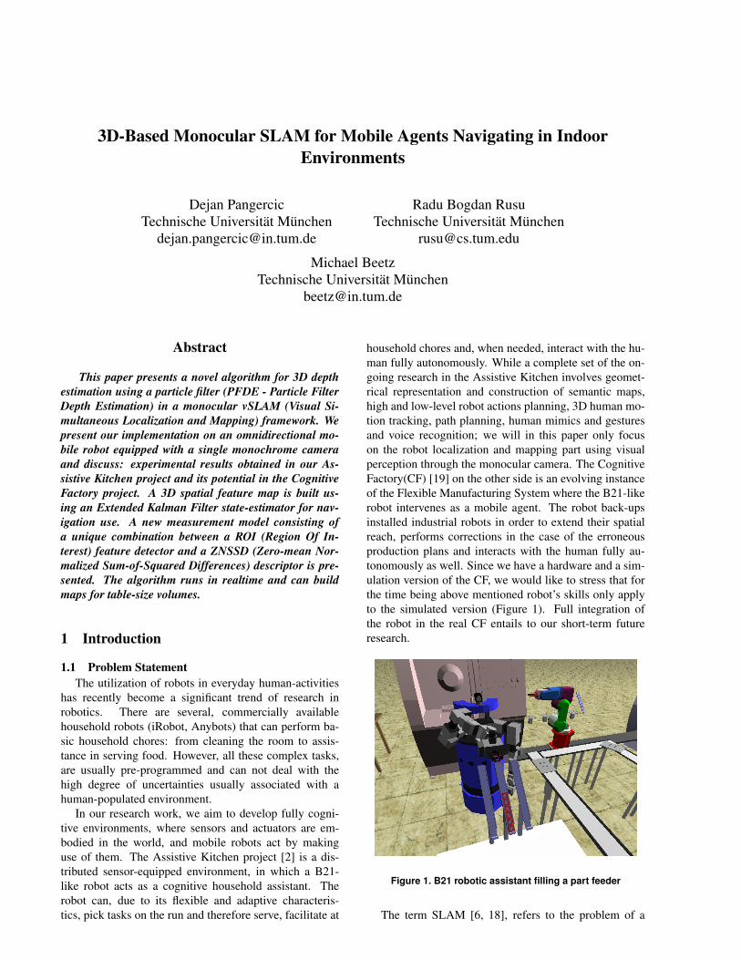
household chores and, when needed, interact with the hu-man fully autonomously. While a complete set of the on-going research in the Assistive Kitchen involves geomet-rical representation and construction of semantic maps,high and low-level robot actions planning, 3D human mo-tion tracking, path planning, human mimics and gesturesand voice recognition; we will in this paper only focuson the robot localization and mapping part using visualperception through the monocular camera. The CognitiveFactory(CF) [19] on the other side is an evolving instanceof the Flexible Manufacturing System where the B21-likerobot intervenes as a mobile agent. The robot back-upsinstalled industrial robots in order to extend their spatialreach, performs corrections in the case of the erroneousproduction plans and interacts with the human fully au-tonomously as well. Since we have a hardware and a sim-ulation version of the CF, we would like to stress that forthe time being above mentioned robot’s skills only applyto the simulated version (Figure 1). Full integration ofthe robot in the real CF entails to our short-term futureresearch.
Figure 1. B21 robotic assistant filling a part feeder
The term SLAM [6, 18], refers to the problem of a
robot concurrently building a representation of the envi-ronment (i.e. map) while navigating around it and keep-ing itself localized. This approach accounts for any arbi-trary moderate-sized indoor environment thus enabling usto turn virtually any casual indoor environment into thecognitive one.
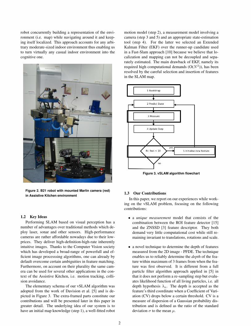
Figure 2. B21 robot with mounted Marlin camera (red)in Assistive Kitchen environment
1.2 Key IdeasPerforming SLAM based on visual perception has a
number of advantages over traditional methods which de-ploy laser, sonar and other sensors. High-performancecameras are rather affordable nowadays due to their low-prices. They deliver high-definition-high-rate inherentlyintuitive images. Thanks to the Computer Vision societywhich has developed a broad-range of powerfull and ef-ficient image processsing algorithms, one can already bydefault overcome certain ambiguities in feature matching.Furthermore, on account on their plurality the same cam-era can be used for several other applications in the con-text of the Assistive Kitchen, i.e. motion tracking, colli-sion avoidance.
The elementary schema of our vSLAM algorithm wasadopted from the work of Davision et al. [5] and is de-picted in Figure 3. The extra-framed parts constitute ourcontributions and will be presented later in this paper ingreater detail. The underlying idea of our system is tohave an initial map knowledge (step 1), a well-fitted robot
motion model (step 2), a measurement model involving acamera (step 3 and 5) and an appropriate state-estimationtool (step 4). For the latter we selected an ExtendedKalman Filter (EKF) over the runner-up candidate usedin a Fast-Slam approach [10] because we believe that lo-calization and mapping can not be decoupled and sepa-rately estimated. The main drawback of EKF, namely itsrequired high computational demands (O(N2)), has beenresolved by the careful selection and insertion of featuresin the SLAM map.
Figure 3. vSLAM algorithm flowchart
1.3 Our ContributionsIn this paper, we report on our experiences while work-
ing on the vSLAM problem, focusing on the followingcontributions:
• a unique measurement model that consists of thecombination between the ROI feature detector [15]and the ZNSSD [3] feature descriptor. They bothdemand very little computational cost while still re-maining invariant to translations, rotations and scale.
• a novel technique to determine the depth of featuresmeasured from the 2D image - PFDE. The techniqueenables us to reliably determine the depth of the fea-ture within maximum of 3 frames from when the fea-ture was first observed. It is different from a fullparticle filter algorithm approach applied in [5] inthat it does not perform a re-sampling step but evalu-ates likelihood function of all living particles, i.e. alldepth hypothesis λn. The depth is accepted as thefeature’s third coordinate when a Coefficient of Vari-ation (CV) drops below a certain threshold. CV is ameasure of dispersion of a Gaussian probability dis-tribution and is defined as the ratio of the standarddeviation σ to the mean µ.
2
The reminder of the paper is structured as follows: Sec-tion 2 revises related work and justifies our ideas for thealgorithm implementation while Section 3 presents ourcore work: novel techniques in the measurement modelpart of the vSLAM algorithm. Section 4 shows the finalexperimental results and Section 5 gives conclusions andfuture look.
2 Related Work
2.1 SLAM OverallThe most common state estimation techniques for solv-
ing a SLAM problem are [13]: Visual Odometry, Fast-SLAM, DP-SLAM, Graph SLAM and Extended KalmanFilter-based SLAM (EKF). We narrowed the selection forour estimator to the FastSLAM and the EKF, as the restof the techniques either only work in a batch mode or areunable to construct long-term consistent maps.
While the FastSLAM is a novel approach, computa-tionally more feasible and solves the full SLAM problem,the EKF is on the other side most frequently applied anda very well tested approach. The ultimate decisive pointfavoring the EKF was also our constraint to bootstrap themap with a certain number of known features which en-ables us to immediately place the EKF in our vSLAM al-gorithm. The algorithm borrows the motion model from,and is similar in the concept to the work of Davison [5],albeit it proposes a different measurement model.
2.2 Vision Perception in SLAMIn one of the first vSLAM works [12], Neira et al. pre-
sented a simple monocular system mapping vertical linesegments in 2D in a constraint indoor environment. Therest of the approaches are using stereo cameras. Jung andLacroix [9] presented a downward-looking stereo systemto localize an airship. The system performs a terrain map-ping and does not run in realtime mode. A work by Simet al. [16] combines SIFTs with FastSLAM filtering andachieves fairly large-scale mapping, however it throttlesprocessor resources by spending on average of 10 secondsper frame. Several authors, like Nister [8], presented sys-tems based on the standard structure from motion method-ology of frame-to-frame correspondences matches. How-ever, these systems are unable to redetect features after theperiods of neglect.
An interest aspect was explored by Sola et al. [17]where they propose to use a Bi-Camera rather then onlyone monocular camera or a stereo set. By this they are ableto a) use a very well understood bearings-only measure-ments from the mono SLAM approach, b) compensate fordownsides of the stereo SLAM, i.e. widen the range oflandmarks’ observability and c) refrain from relying onthe stereo rig calibration. Encouraged by the possibilityto upgrade to the Sola’s work if needed, and the fact thatstereo-based vSLAM is computationally more expensive,we decided to build our algorithm based on the monocularcamera measurements.
3 Measurement Model
Our motion model accounts for 6 Degrees Of Freedom(DOFs) and is in fact redundant for the planar-like setupsthat we have (translation in x− z plane, rotation around yaxis in cartesian world frame). However, we have noticedthat translation along, and rotations around unused axes,on average always converge to zero and we therefore con-sidered them as non-perturbating factors.
The measurement part of our vSLAM algorithm assertsan initialization and matching of the features. The SLAMmap is bootstrapped with 4 manually inserted, consis-tent features with known positions and covariances in theworld coordinate frame while the rest of them are broughtin the map using PFDE. Estimated 3D feature positionsare projected into the 2D image over the camera perspec-tive projection model and measured in order to yield adiscrepancy (innovation) between the projected and theactual patch position [13]. In the following sections wediscuss the operations performed on consistent features inthe image plane, as well as the process of initializationand matching of the Newly Initialized Feature (NIF). Wealso present its transformation to the 3-element consistentrepresentation using PFDE.
3.1 Feature DetectorWe utilized an industrial camera type Marlin F-
046C from Allied Vision Technologies, which deliversmonochrome, 8-bit, 320×240 pixels images.
Distinctive features in the image were detected by theROI operator which is elementary similar to a Harris Cor-ner Detector (HCD) [7]. Second-order derivatives gxx,gyy , gxy in x, y, and xy directions over a patch of theimage (we use a 11× 11 pixels patch) are calculated, anda 2× 2 symmetric covariance matrix D is built.
By performing eigenanalysis, the least of the twoeigenvalues e of the given covariance matrix D arechecked against an eigenvalue magnitude threshold(threshold < max(e)). If this threshold condition is full-filed, the feature with the largest eigenvalue magnitude isdeemed salient and gets extracted.
D =
[gxx gxy
gyx gyy
](1)
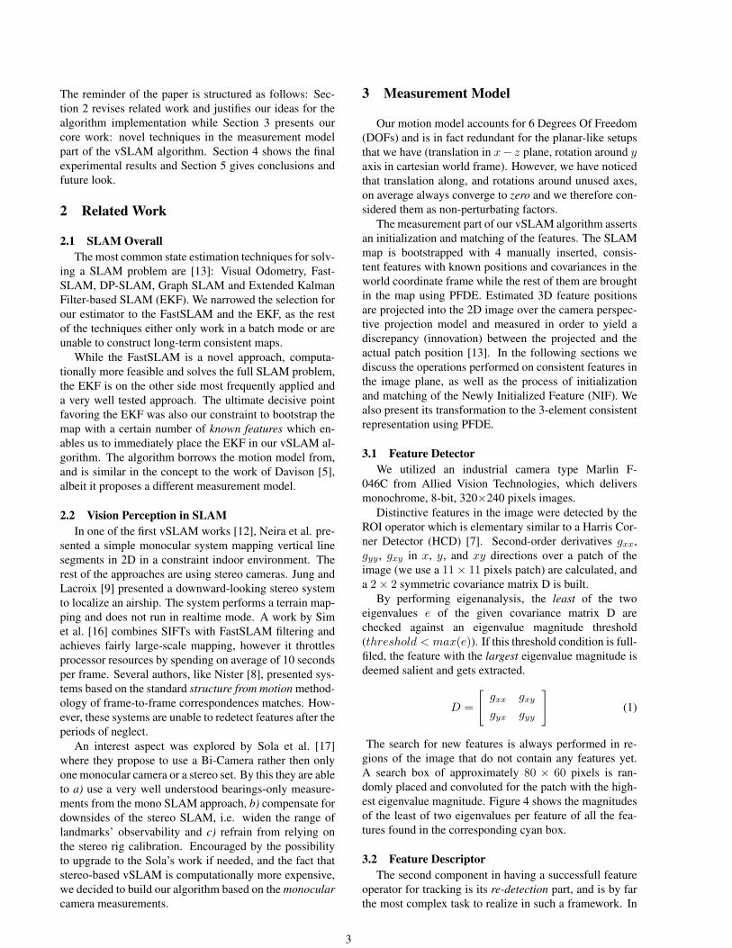
The search for new features is always performed in re-gions of the image that do not contain any features yet.A search box of approximately 80 × 60 pixels is ran-domly placed and convoluted for the patch with the high-est eigenvalue magnitude. Figure 4 shows the magnitudesof the least of two eigenvalues per feature of all the fea-tures found in the corresponding cyan box.
3.2 Feature DescriptorThe second component in having a successfull feature
operator for tracking is its re-detection part, and is by farthe most complex task to realize in such a framework. In
3
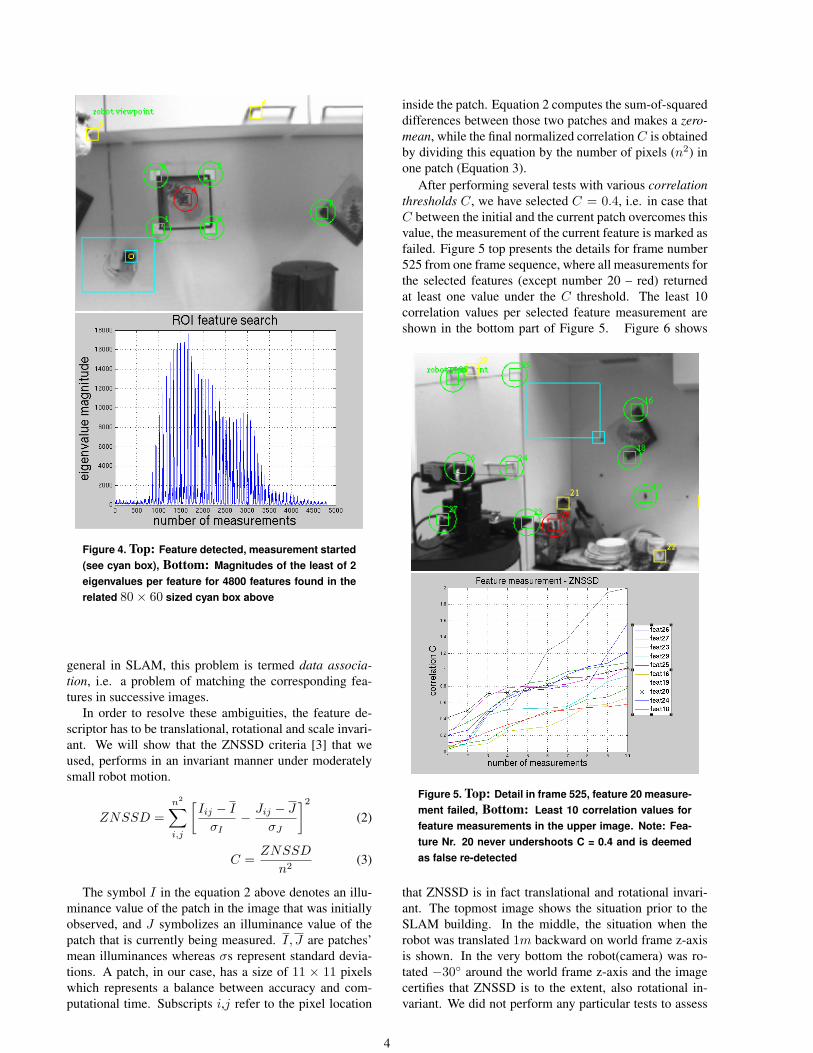
Figure 4. Top: Feature detected, measurement started(see cyan box), Bottom: Magnitudes of the least of 2eigenvalues per feature for 4800 features found in therelated 80× 60 sized cyan box above
general in SLAM, this problem is termed data associa-tion, i.e. a problem of matching the corresponding fea-tures in successive images.
In order to resolve these ambiguities, the feature de-scriptor has to be translational, rotational and scale invari-ant. We will show that the ZNSSD criteria [3] that weused, performs in an invariant manner under moderatelysmall robot motion.
ZNSSD =n2∑i,j
[Iij − I
σI− Jij − J
σJ
]2
(2)
C =ZNSSD
n2(3)
The symbol I in the equation 2 above denotes an illu-minance value of the patch in the image that was initiallyobserved, and J symbolizes an illuminance value of thepatch that is currently being measured. I, J are patches’mean illuminances whereas σs represent standard devia-tions. A patch, in our case, has a size of 11 × 11 pixelswhich represents a balance between accuracy and com-putational time. Subscripts i,j refer to the pixel location
inside the patch. Equation 2 computes the sum-of-squareddifferences between those two patches and makes a zero-mean, while the final normalized correlation C is obtainedby dividing this equation by the number of pixels (n2) inone patch (Equation 3).
After performing several tests with various correlationthresholds C, we have selected C = 0.4, i.e. in case thatC between the initial and the current patch overcomes thisvalue, the measurement of the current feature is marked asfailed. Figure 5 top presents the details for frame number525 from one frame sequence, where all measurements forthe selected features (except number 20 – red) returnedat least one value under the C threshold. The least 10correlation values per selected feature measurement areshown in the bottom part of Figure 5. Figure 6 shows
Figure 5. Top: Detail in frame 525, feature 20 measure-ment failed, Bottom: Least 10 correlation values forfeature measurements in the upper image. Note: Fea-ture Nr. 20 never undershoots C = 0.4 and is deemedas false re-detected
that ZNSSD is in fact translational and rotational invari-ant. The topmost image shows the situation prior to theSLAM building. In the middle, the situation when therobot was translated 1m backward on world frame z-axisis shown. In the very bottom the robot(camera) was ro-tated −30◦ around the world frame z-axis and the imagecertifies that ZNSSD is to the extent, also rotational in-variant. We did not perform any particular tests to assess
4
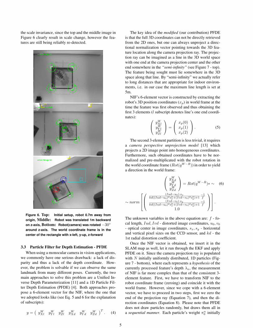
the scale invariance, since the top and the middle image inFigure 6 clearly result in scale change, however the fea-tures are still being reliably re-detected.
Figure 6. Top: Initial setup, robot 0.7m away fromorigin, Middle: Robot was translated 1m backwardon z-axis, Bottom: Robot(camera) was rotated−30◦
around z-axis. The world coordinate frame is in thecenter of the rectangle with x-left, y-up, z-forward
3.3 Particle Filter for Depth Estimation - PFDEWhen using a monocular camera in vision applications,
we commonly have one serious drawback: a lack of dis-parity and thus a lack of the depth coordinate. How-ever, the problem is solvable if we can observe the samelandmark from many different poses. Currently, the twomain approaches to solve this problem are a Unified In-verse Depth Parameterization [11] and a 1D Particle Fil-ter Depth Estimation (PFDE) [4]. Both approaches pro-pose a 6-element vector for the NIF, where the one thatwe adopted looks like (see Eq. 5 and 6 for the explanationof subscripts):
y =(
yWXl yW
Y l yWZl yW
Xd yWY d yW
Zd
)T. (4)
The key idea of the modified (our contribution) PFDEis that the full 3D coordinates can not be directly retrievedfrom the 2D ones, but one can always unproject a direc-tional normalization vector pointing towards the 3D fea-ture location along the camera projection ray. The projec-tion ray can be imagined as a line in the 3D world spacewith one end at the camera projection center and the otherend somewhere in the “semi-infinity” (see Figure 7 - top).The feature being sought must lie somewhere in the 3Dspace along that line. By “semi-infinity” we actually referto long distances that are appropriate for indoor environ-ments, i.e. in our case the maximum line length is set at5m.
NIF’s 6-element vector is constructed by extracting therobot’s 3D position coordinates (xp) in world frame at thetime the feature was first observed and thus obtaining thefirst 3 elements (l subscript denotes line’s one end coordi-nates): yW
Xl
yWY l
yWZl
=
xp(0)xp(1)xp(2)
. (5)
The second 3-element partition is less trivial, it requiresa camera perspective unprojection model [13] whichprojects a 2D image point into homogeneous coordinates.Furthermore, such obtained coordinates have to be nor-malized and pre-multiplicated with the robot rotation inthe world coordinate frame (Rot(qW−R)) in order to yielda direction in the world frame: yW
Xd
yWY d
yWZd
= Rot(qW−R)∗ ∼ (6)
∼ norm
(Iud−u0)·sx
kd((Iud−u0)2s2x+(Ivd−v0)2s2
y)+1−1f
(Ivd−v0)·sy
kd((Iud−u0)2s2x+(Ivd−v0)2s2
y)+1−1f
1.0
.
The unknown variables in the above equation are: f - fo-cal length, Iud, Ivd - distorted image coordinates, u0, v0
- optical center in image coordinates, sx, sy - horizontaland vertical pixel sizes on the CCD sensor, and kd - the1st radial distortion coefficient.
Once the NIF vector is obtained, we insert it in theSLAM map as well, let it run through the EKF and applyPFDE on it. Since the camera projection ray is populatedwith N initially uniformly distributed, 1D particles (Fig-ure 7 - bottom), where each represents a hypothesis of thecurrently processed feature’s depth λn, the measurementof NIF is far more complex than that of the consistent 3-element feature. First, we have to transform NIF to therobot coordinate frame (zeroing) and coincide it with theworld frame. However, since we cope with a 6-elementvector, we have to proceed in two steps, first we zero theend of the projection ray (Equation 7), and then the di-rection coordinates (Equation 8). Please note that PFDEdoes not draw particles randomly, but draws them all ina sequential manner. Each particle’s weight πn
0 initially
5
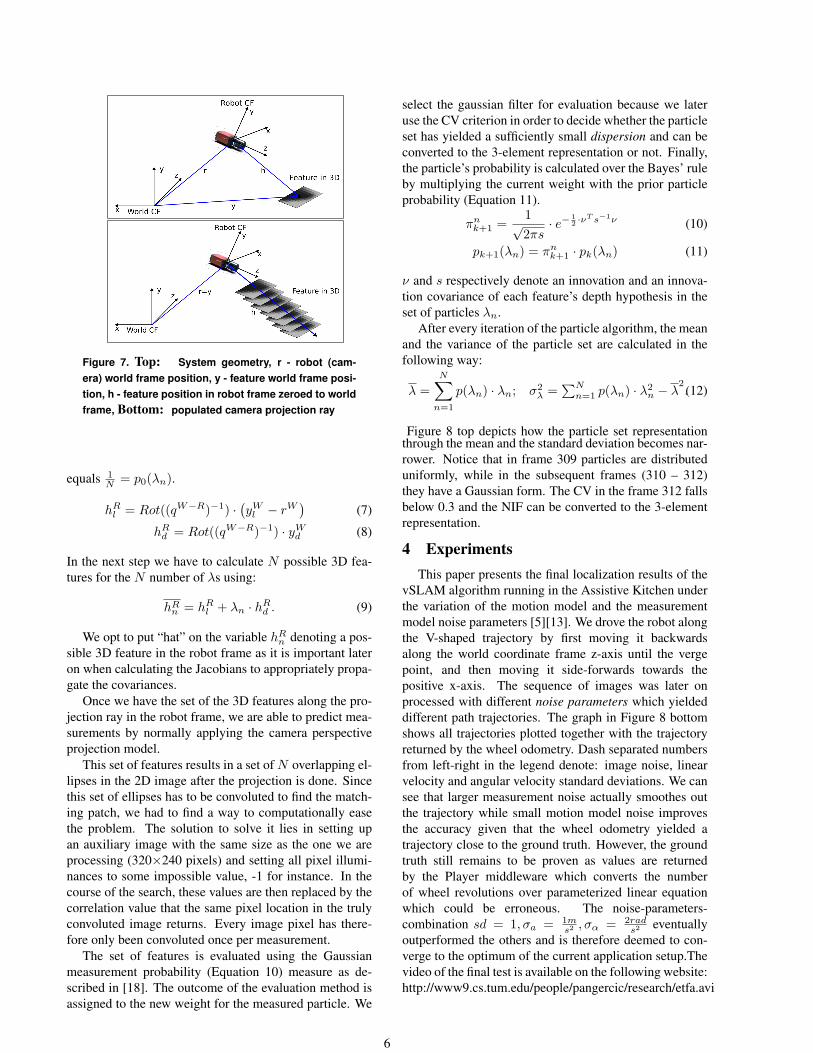
Figure 7. Top: System geometry, r - robot (cam-era) world frame position, y - feature world frame posi-tion, h - feature position in robot frame zeroed to worldframe, Bottom: populated camera projection ray
equals 1N = p0(λn).
hRl = Rot((qW−R)−1) ·
(yW
l − rW)
(7)
hRd = Rot((qW−R)−1) · yW
d (8)
In the next step we have to calculate N possible 3D fea-tures for the N number of λs using:
hRn = hR
l + λn · hRd . (9)
We opt to put “hat” on the variable hRn denoting a pos-
sible 3D feature in the robot frame as it is important lateron when calculating the Jacobians to appropriately propa-gate the covariances.
Once we have the set of the 3D features along the pro-jection ray in the robot frame, we are able to predict mea-surements by normally applying the camera perspectiveprojection model.
This set of features results in a set of N overlapping el-lipses in the 2D image after the projection is done. Sincethis set of ellipses has to be convoluted to find the match-ing patch, we had to find a way to computationally easethe problem. The solution to solve it lies in setting upan auxiliary image with the same size as the one we areprocessing (320×240 pixels) and setting all pixel illumi-nances to some impossible value, -1 for instance. In thecourse of the search, these values are then replaced by thecorrelation value that the same pixel location in the trulyconvoluted image returns. Every image pixel has there-fore only been convoluted once per measurement.
The set of features is evaluated using the Gaussianmeasurement probability (Equation 10) measure as de-scribed in [18]. The outcome of the evaluation method isassigned to the new weight for the measured particle. We
select the gaussian filter for evaluation because we lateruse the CV criterion in order to decide whether the particleset has yielded a sufficiently small dispersion and can beconverted to the 3-element representation or not. Finally,the particle’s probability is calculated over the Bayes’ ruleby multiplying the current weight with the prior particleprobability (Equation 11).
πnk+1 =
1√2πs
· e− 12 ·ν
T s−1ν (10)
pk+1(λn) = πnk+1 · pk(λn) (11)
ν and s respectively denote an innovation and an innova-tion covariance of each feature’s depth hypothesis in theset of particles λn.
After every iteration of the particle algorithm, the meanand the variance of the particle set are calculated in thefollowing way:
λ =N∑
n=1
p(λn) · λn; σ2λ =
∑Nn=1 p(λn) · λ2
n − λ2.(12)
Figure 8 top depicts how the particle set representationthrough the mean and the standard deviation becomes nar-rower. Notice that in frame 309 particles are distributeduniformly, while in the subsequent frames (310 – 312)they have a Gaussian form. The CV in the frame 312 fallsbelow 0.3 and the NIF can be converted to the 3-elementrepresentation.
4 ExperimentsThis paper presents the final localization results of the
vSLAM algorithm running in the Assistive Kitchen underthe variation of the motion model and the measurementmodel noise parameters [5][13]. We drove the robot alongthe V-shaped trajectory by first moving it backwardsalong the world coordinate frame z-axis until the vergepoint, and then moving it side-forwards towards thepositive x-axis. The sequence of images was later onprocessed with different noise parameters which yieldeddifferent path trajectories. The graph in Figure 8 bottomshows all trajectories plotted together with the trajectoryreturned by the wheel odometry. Dash separated numbersfrom left-right in the legend denote: image noise, linearvelocity and angular velocity standard deviations. We cansee that larger measurement noise actually smoothes outthe trajectory while small motion model noise improvesthe accuracy given that the wheel odometry yielded atrajectory close to the ground truth. However, the groundtruth still remains to be proven as values are returnedby the Player middleware which converts the numberof wheel revolutions over parameterized linear equationwhich could be erroneous. The noise-parameters-combination sd = 1, σa = 1m
s2 , σα = 2rads2 eventually
outperformed the others and is therefore deemed to con-verge to the optimum of the current application setup.Thevideo of the final test is available on the following website:http://www9.cs.tum.edu/people/pangercic/research/etfa.avi
6
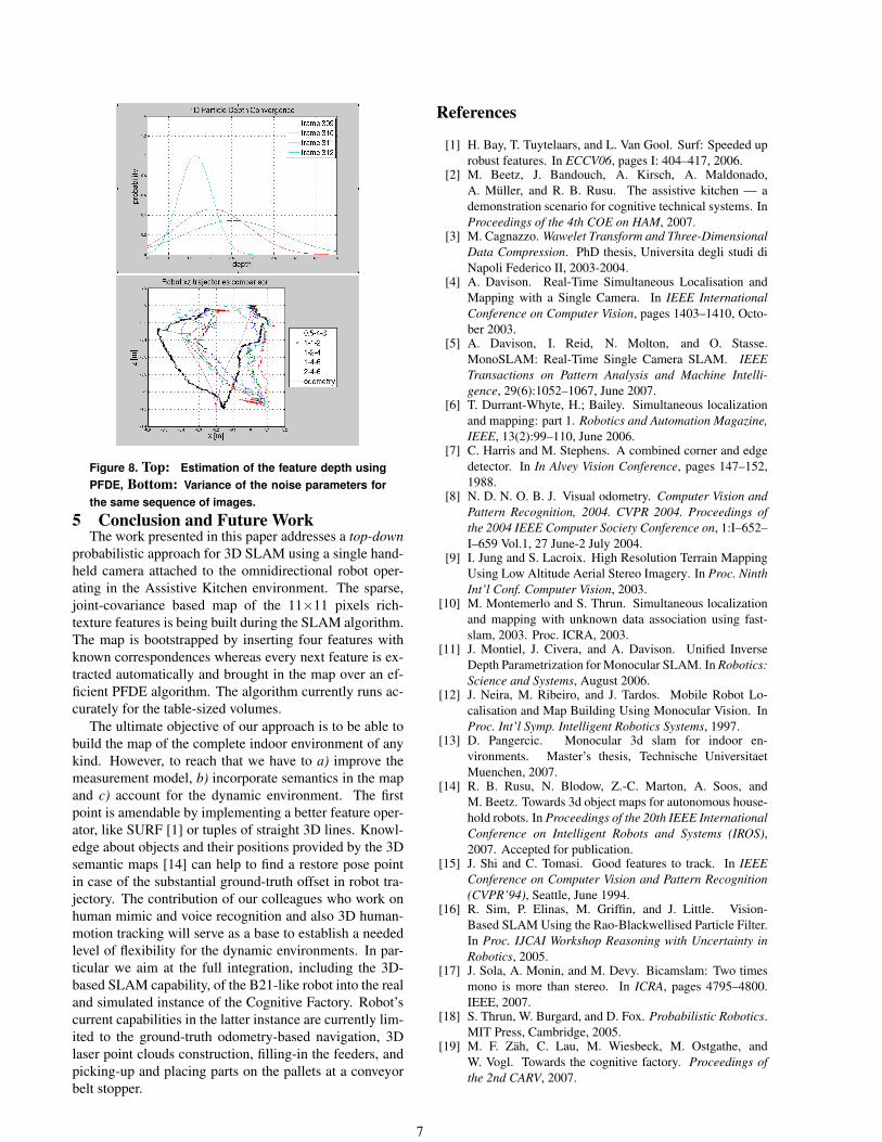
Figure 8. Top: Estimation of the feature depth usingPFDE, Bottom: Variance of the noise parameters forthe same sequence of images.
5 Conclusion and Future WorkThe work presented in this paper addresses a top-down
probabilistic approach for 3D SLAM using a single hand-held camera attached to the omnidirectional robot oper-ating in the Assistive Kitchen environment. The sparse,joint-covariance based map of the 11×11 pixels rich-texture features is being built during the SLAM algorithm.The map is bootstrapped by inserting four features withknown correspondences whereas every next feature is ex-tracted automatically and brought in the map over an ef-ficient PFDE algorithm. The algorithm currently runs ac-curately for the table-sized volumes.
The ultimate objective of our approach is to be able tobuild the map of the complete indoor environment of anykind. However, to reach that we have to a) improve themeasurement model, b) incorporate semantics in the mapand c) account for the dynamic environment. The firstpoint is amendable by implementing a better feature oper-ator, like SURF [1] or tuples of straight 3D lines. Knowl-edge about objects and their positions provided by the 3Dsemantic maps [14] can help to find a restore pose pointin case of the substantial ground-truth offset in robot tra-jectory. The contribution of our colleagues who work onhuman mimic and voice recognition and also 3D human-motion tracking will serve as a base to establish a neededlevel of flexibility for the dynamic environments. In par-ticular we aim at the full integration, including the 3D-based SLAM capability, of the B21-like robot into the realand simulated instance of the Cognitive Factory. Robot’scurrent capabilities in the latter instance are currently lim-ited to the ground-truth odometry-based navigation, 3Dlaser point clouds construction, filling-in the feeders, andpicking-up and placing parts on the pallets at a conveyorbelt stopper.
References
[1] H. Bay, T. Tuytelaars, and L. Van Gool. Surf: Speeded uprobust features. In ECCV06, pages I: 404–417, 2006.
[2] M. Beetz, J. Bandouch, A. Kirsch, A. Maldonado,A. Muller, and R. B. Rusu. The assistive kitchen — ademonstration scenario for cognitive technical systems. InProceedings of the 4th COE on HAM, 2007.
[3] M. Cagnazzo. Wawelet Transform and Three-DimensionalData Compression. PhD thesis, Universita degli studi diNapoli Federico II, 2003-2004.
[4] A. Davison. Real-Time Simultaneous Localisation andMapping with a Single Camera. In IEEE InternationalConference on Computer Vision, pages 1403–1410, Octo-ber 2003.
[5] A. Davison, I. Reid, N. Molton, and O. Stasse.MonoSLAM: Real-Time Single Camera SLAM. IEEETransactions on Pattern Analysis and Machine Intelli-gence, 29(6):1052–1067, June 2007.
[6] T. Durrant-Whyte, H.; Bailey. Simultaneous localizationand mapping: part 1. Robotics and Automation Magazine,IEEE, 13(2):99–110, June 2006.
[7] C. Harris and M. Stephens. A combined corner and edgedetector. In In Alvey Vision Conference, pages 147–152,1988.
[8] N. D. N. O. B. J. Visual odometry. Computer Vision andPattern Recognition, 2004. CVPR 2004. Proceedings ofthe 2004 IEEE Computer Society Conference on, 1:I–652–I–659 Vol.1, 27 June-2 July 2004.
[9] I. Jung and S. Lacroix. High Resolution Terrain MappingUsing Low Altitude Aerial Stereo Imagery. In Proc. NinthInt’l Conf. Computer Vision, 2003.
[10] M. Montemerlo and S. Thrun. Simultaneous localizationand mapping with unknown data association using fast-slam, 2003. Proc. ICRA, 2003.
[11] J. Montiel, J. Civera, and A. Davison. Unified InverseDepth Parametrization for Monocular SLAM. In Robotics:Science and Systems, August 2006.
[12] J. Neira, M. Ribeiro, and J. Tardos. Mobile Robot Lo-calisation and Map Building Using Monocular Vision. InProc. Int’l Symp. Intelligent Robotics Systems, 1997.
[13] D. Pangercic. Monocular 3d slam for indoor en-vironments. Master’s thesis, Technische UniversitaetMuenchen, 2007.
[14] R. B. Rusu, N. Blodow, Z.-C. Marton, A. Soos, andM. Beetz. Towards 3d object maps for autonomous house-hold robots. In Proceedings of the 20th IEEE InternationalConference on Intelligent Robots and Systems (IROS),2007. Accepted for publication.
[15] J. Shi and C. Tomasi. Good features to track. In IEEEConference on Computer Vision and Pattern Recognition(CVPR’94), Seattle, June 1994.
[16] R. Sim, P. Elinas, M. Griffin, and J. Little. Vision-Based SLAM Using the Rao-Blackwellised Particle Filter.In Proc. IJCAI Workshop Reasoning with Uncertainty inRobotics, 2005.
[17] J. Sola, A. Monin, and M. Devy. Bicamslam: Two timesmono is more than stereo. In ICRA, pages 4795–4800.IEEE, 2007.
[18] S. Thrun, W. Burgard, and D. Fox. Probabilistic Robotics.MIT Press, Cambridge, 2005.
[19] M. F. Zah, C. Lau, M. Wiesbeck, M. Ostgathe, andW. Vogl. Towards the cognitive factory. Proceedings ofthe 2nd CARV, 2007.
7

![EGO-SLAM: A Robust Monocular SLAM for …arXiv:1707.05564v2 [cs.CV] 17 Nov 2018 In this paper, we investigate the monocular SLAM prob-lem with a special emphasis on EGOcentric videos,](https://img.pdfslide.us/doc/110x75/5fe2bff5b533fd76167f3e75/ego-slam-a-robust-monocular-slam-for-arxiv170705564v2-cscv-17-nov-2018-in.jpg)


![EGO-SLAM: A Robust Monocular SLAM for Egocentric Videossuvam/rslam_wacv19_camera_ready.pdf · Figure 1: Incremental nature of state of the art SLAM [32,9,19] as well as SFM [56,55,50]](https://img.pdfslide.us/doc/110x75/601f57958b217666bc405b71/ego-slam-a-robust-monocular-slam-for-egocentric-suvamrslamwacv19camerareadypdf.jpg)