Embed Size (px)
Citation preview

3D Analysis of Seepage under Hydraulic Structures with IntermediateFilters
Ahmed, A., McLoughlin, S., & Johnston, H. (2015). 3D Analysis of Seepage under Hydraulic Structures withIntermediate Filters. Journal of Hydraulic Engineering, 141(1), 06014019-1 -06014019-6.https://doi.org/10.1061/(ASCE)HY.1943-7900.0000944
Published in:Journal of Hydraulic Engineering
Document Version:Peer reviewed version
Queen's University Belfast - Research Portal:Link to publication record in Queen's University Belfast Research Portal
Publisher rights© ASCE 2015.
General rightsCopyright for the publications made accessible via the Queen's University Belfast Research Portal is retained by the author(s) and / or othercopyright owners and it is a condition of accessing these publications that users recognise and abide by the legal requirements associatedwith these rights.
Take down policyThe Research Portal is Queen's institutional repository that provides access to Queen's research output. Every effort has been made toensure that content in the Research Portal does not infringe any person's rights, or applicable UK laws. If you discover content in theResearch Portal that you believe breaches copyright or violates any law, please contact [email protected].
Download date:31. Dec. 2021

1
3D Seepage under Hydraulic Structures Provided with Intermediate Filters 1 2
Ashraf Ahmed1, Shane McLoughlin2, and Harold Johnston3 3 4
1 Lecturer, School of Planning, Architecture, and Civil Engineering, Queen’s University Belfast, David 5 Kier building, Stranmillis Road, Belfast BT95AG, UK 6 7 2 Student, School of Planning, Architecture, and Civil Engineering, Queen’s University Belfast, David Kier 8 building, Stranmillis Road, Belfast BT95AG, UK 9 10 3 Senior lecturer, School of Planning, Architecture, and Civil Engineering, Queen’s University Belfast, 11 David Kier building, Stranmillis Road, Belfast BT95AG, UK 12 13 14
Abstract 15 Seepage flow under hydraulic structures provided with intermediate filters has been 16
investigated. The flow through the banks of the canal has been included in the model. 17
Different combinations of intermediate filter and canal width were studied. Different lengths 18
of the floor, differential heads, and depths of the sheetpile driven beneath the floor were also 19
investigated. It was found that the introduction of an intermediate filter to the floor of 20
hydraulic structures reduced the uplift force acting on the downstream floor by up to 72%. 21
The maximum uplift reduction occurred when the distance of filter location downstream the 22
cutoff to the differential head ratio was 1. Introducing a second filter in the downstream side 23
resulted in a further reduction in the exit hydraulic gradient and in the uplift force, which 24
reached 90%. The optimum locations of the two filters occurred when the first filter was 25
placed just downstream the cutoff wall and the second filter was placed nearly at the mid-26
distance between the cutoff and the end toe of the floor. The results showed significant 27
differences between the three-dimensional (3D) and the two-dimensional (2D) analyses. 28
Keywords: Weirs; Regulators; Dams; Control structures; Mathematical modeling; 29
Intermediate filters 30
Introduction 31
Hydraulic structures are used to control the flow of water in rivers and canals. It is necessary 32
to minimize the uplift pressures and hydraulic gradients beneath such structures to prevent 33

2
flotation, to ensure their structural stability, and to design against soil piping and consequent 34
undermining of the structure. It is common to install cutoff walls beneath the floors of 35
hydraulic strictures to reduce the seepage flow. In addition, intermediate filters are often 36
provided in the floor of the structure as a further measure to reduce the uplift forces and exit 37
hydraulic gradients. The effectiveness of these filters in reducing uplift forces has been 38
analyzed using analytical methods. 39
Conformal mapping has been used to produce exact solutions for the problem of 2D seepage 40
beneath a hydraulic structure with a flat floor having two end cutoffs and a filter located at 41
various positions in the floor (Chawla 1975; Kumar et al. 1986). Elganainy (1986) presented 42
a solution for the problem of seepage beneath two structures with intermediate filter built on 43
two pervious strata. Hathoot (1986) used the Schwartz-Christoffel transformation to solve the 44
problem of seepage beneath a concrete dam with a downstream filter. 45
The case of 2D seepage flow beneath a hydraulic structure provided with two intermediate 46
filters was also studied using conformal mapping (Farouk and smith 2000). Salem et al. 47
(2001) used the Schwartz-Christoffel transformation to examine the stability of two 48
consecutive floors with intermediate filter. The two consecutive floors represent a subsidiary 49
weir constructed downstream of a barrage, a scheme which is equivalent to a physical 50
situation resulting from the construction of subsidiary weirs downstream of barrages on the 51
Nile river in Egypt. 52
Several studies conducted 3D numerical analysis to analyse the problem of seepage under 53
hydraulic structures. Griffiths and Fenton (1997) studied 3D seepage through spatially 54
random soil. The 3D results compared favorably with the 2D results for the same structure. 55
More recently, Ahmed et al. (2007) studied the problem of 3D seepage under hydraulic 56
structures with leakage through the sheetpiles. A limitation in these studies was that they 57
have not considered the seepage flow through the canal banks. Studies carried out by Ahmed 58

3
and Bazaraa (2009) and Ahmed (2011) showed that neglecting the seepage flow through the 59
banks of a canal resulted in errors in the seepage calculations. 60
The problem of 3D seepage beneath a hydraulic structure with a floor provided with an 61
intermediate filter has not been investigated before. In this study, the effect of one and two 62
intermediate filters on the development of uplift forces and exit hydraulic gradients at the 63
downstream edge of a hydraulic structure has been analyzed. A number of analyses were 64
carried out to investigate the effect of filter length, filter location and the introduction of a 65
second filter on the development of uplift forces and exit hydraulic gradients. The analysis 66
was carried out for various canal widths. Seepage through the canal banks was taken into 67
account and the unsaturated flow above the free surface was considered. 68
The Finite Element Model and the Analysis procedure 69
The model deals with both confined and free surface flow problems. A detailed presentation 70
of this computer program, and its validation and applications can be found in Ahmed (2008, 71
2009). The program uses the model of van Genuchten (1980) to include the unsaturated 72
flow. 73
Fig 1 illustrates an isometric view of the configuration studied; a hydraulic structure 74
constructed upon a pervious homogeneous isotropic soil of depth 6m and hydraulic 75
conductivity k=3 x 10⁻⁵ m/s. The van Genuchten curve fitting parameters were taken α = 14.5 76
m-1 and n=2.68. The structure includes the floor, the side retaining walls and the structure 77
built above the floor, all of which are considered to be impervious. A sheetpile cutoff driven 78
to a depth of 4 m under the structure was represented. Different sheetpile depths were also 79
investigated. The length of the modeled zone was 60 m and the upstream and downstream 80
edges of the zone were considered to be impermeable. A differential head of H=1 m between 81
the upstream and downstream sides of the structure produced the seepage flow. The ratio of 82

4
the floor length to differential head L/H was 16. Other ratios of L/H=20 and 24 were also 83
investigated. The top of the banks was 2 m above the bed of the canal. 84
The finite element mesh used for the problem has a total of 10878 nodes and 9184 brick 85
elements. Only one half of the problem was simulated because of its symmetry about the 86
canal centerline. A 2D analysis was carried out on each case and the values of uplift forces 87
and the exit hydraulic gradient acting on the downstream side of the structure were 88
calculated. The problem was then studied in 3D for varying ratios of canal width to 89
differential head W/H from 2 to 14. For each W/H ratio, scenarios of no filter, one filter, and 90
two filters were analyzed. If x denotes the distance from the cutoff to the filter location (see 91
Fig 1), the problem was studied for the ratio x/H varying from 1 to 6 for both the one and two 92
filters scenarios. A comparison of the 2D and 3D results was carried out for each case. 93
Results and Discussion of One Intermediate Filter 94
The Effect of the Filter Location 95
Fig 2 presents different sections perpendicular to the canal centerline showing the free 96
surface positions both upstream and downstream sides of the floor. As expected, the water 97
flows out from the canal into the banks in the upstream side and then flows from the banks 98
into the canal on the downstream side. It is therefore important to take the flow through the 99
banks into consideration. Modelling this problem in 2D (e.g. Chawla 1975, Farouk and smith 100
2000) or in 3D without considering the flow through the banks has not provided accurate 101
analysis that can be used in the design of the structure. The free surface at a distance of 10 m 102
upstream and downstream of the structure was nearly flat. 103
Fig 3 presents the average uplift forces on the floor, when there was one filter, for different 104
ratios of W/H. The filter location was measured from the sheet pile cutoff to the upstream 105
edge of the filter. The uplift force shown in the figure is normalized relative to the case of no 106

5
filter in place. The introduction of a filter to the floor of the structure, regardless of its 107
location, significantly reduced the uplift force developed under the floor. The smallest 108
reduction in uplift force occurred when W/H= 2 where the reductions varied from 56% to 109
33% as x/H varied from 1 to 6, respectively. As the ratio W/H increased, the potential for 110
uplift reduction also increased. For W/H=14, the reduction in uplift force varied from 72% to 111
35% as the ratio x/H varied from 1 to 6, respectively. For x/H =1 to 2, only slight or no 112
change was observed in the uplift force. 113
The greatest reduction in the uplift force occurred when x/H=1. This is because the uplift 114
pressure is higher just downstream the cutoff than at any other point in the downstream side. 115
The filter intercepts some of the streamlines and hence breaks the development of the uplift 116
pressure. The above results in Fig 3 mean that placing a filter at this position will have a 117
greater impact than at any other position. 118
Fig 4 presents the exit hydraulic gradients along the canal width for different filter locations. 119
The exit hydraulic gradient calculated at the center of the canal was smaller than its value at 120
the canal edge because of the water seepage through the banks. The water flows through the 121
banks at a faster rate than below the structure. This is attributed to the existence of sheet pile 122
below the floor that increases the travelling distance of the flowing water. Fig 4 shows again 123
the importance of undertaking a 3D analysis of seepage problems since the exit hydraulic 124
gradient obtained from the 2D analysis is that for the canal center. The 2D analysis also 125
disregards seepage through the canal banks. 126
Fig 5 illustrates the impact the filter location had on the exit hydraulic gradient observed at 127
the edge and at the centerline of the canal. All filter locations with x/H= 1 to 5 had little effect 128
on the exit hydraulic gradient. A filter placed with x/H = 6 was found to further reduce the 129
exit gradient. This happened both at the edge and at the center of the canal. However, the exit 130
hydraulic gradient for all of these locations was reduced compared to the case of no filter in 131

6
place. The main reason for this reduction in exit gradient is because the filter intercepts some 132
streamlines. Both the central and edge exit hydraulic gradients calculated using the 3D model 133
were greater than the value obtained from the 2D model. As the W/H ratio increased from 2 134
to 14, the central exit hydraulic gradient decreased and became comparable to the results of 135
the 2D model. 136
The Effect of Filter Length 137
The effect of the filter length on the uplift pressure developed beneath the floor was analyzed 138
using W/H ratios of 8 and 12. The filter length is taken as the dimension in the longitudinal 139
direction of the canal. The results of this analysis are shown in Fig. 6. Increasing the length 140
of the filter reduced the uplift force further; however the magnitude of this reduction was not 141
significant when compared with the reduction produced from placing the filter in the 142
downstream side. 143
Obviously, the existence of a filter, even with small length, is still able to break the 144
development of the uplift pressure on the downstream floor. Hence, the increase in the filter 145
length did not lead to a significant further reduction in the uplift force. These findings 146
confirm those of Chawla (1975), and Farouk and Smith (2000). Increasing the filter length 147
caused a small reduction in the exit hydraulic gradient at the edge and at the center of the 148
canal. 149
Different Depths of Sheetpile 150
In addition to the 4 m deep sheetpile presented in Figs 3, and 5, a depth of the sheetpile cutoff 151
of 2 m was tested for different locations of the intermediate filter. The percentage reductions 152
in the exit gradient, and uplift force made by the filter for this case were similar to the 153
percentage reductions made by the 4 m sheetpile. The only difference was that the absolute 154

7
values of the uplift force and the exit gradient obtained were slightly greater than the values 155
obtained for 4 m deep sheetpile. 156
Results and Discussion of Two Intermediate Filters 157
The provision of a second filter to the floor of the structure reduced the uplift force beneath 158
the floor significantly (Fig 7). The greatest reduction in the uplift force occurred when the 159
two filters were located at x/H =1 and 4. For these two filter locations, the maximum 160
reduction in the uplift force was 80% when W/H =2. Increasing W/H to 14 led to reduction in 161
the uplift force by 90%. 162
The optimum position of the filters downstream of the sheet pile cutoff changed as the floor 163
length to differential head ratio L/H varied (Fig 8). When L/H was increased to 24, the 164
optimum locations of the filters occurred at ratios of x/H of 1 and 5. 165
The downstream floor can be considered as three sections for analysis. Pore water pressure 166
develops on the first section between the cutoff and the first filter. The first filter then 167
intercepts some of the flow lines preventing the build-up of pore pressure along its length. 168
Pore water pressure increases on the second section of the floor between the two filters. The 169
second filter reduces the pore water pressure along its length and the pore water pressure 170
increases again over the third section of the floor between the second filter and the 171
downstream edge. The total pressure on the floor is less than the total pressure that is 172
developed with either one or no filter in place. 173
Comparison with 2D Results 174
The uplift force calculated using the 3D model was comparable to its 2D value when W/H > 175
10 as shown in Fig 7. When W/H <10, the uplift force resulting from the 3D model was 176
greater than that obtained from the 2D solution. When W/H <10, the seepage flow through 177
the banks is significant compared to the flow beneath the floor, which is always reduced by 178
8
one or more rows of cutoff walls that are usually driven below the floor. This may be the 179
reason behind the increased 3D uplift force for narrow canals. 180
In the 3D flow, the unsaturated flow through the banks may play a role in the difference 181
between 2D and 3D results. For the 2D analysis of this problem, the flow is confined, and 182
hence only saturated flow is considered. However, for the problem investigated in this 183
research, the unsaturated flow was minimal. This may be attributed to the soil type used in 184
the current analysis, or the fact that the free surface was only 1 m below the top level of the 185
bank. The effect of unsaturated flow in 3D flow problems under hydraulic structures needs 186
further investigations for different soil types, and different structures configurations. 187
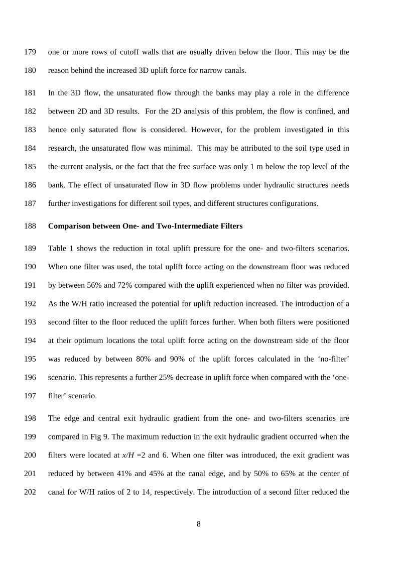
Comparison between One- and Two-Intermediate Filters 188
Table 1 shows the reduction in total uplift pressure for the one- and two-filters scenarios. 189
When one filter was used, the total uplift force acting on the downstream floor was reduced 190
by between 56% and 72% compared with the uplift experienced when no filter was provided. 191
As the W/H ratio increased the potential for uplift reduction increased. The introduction of a 192
second filter to the floor reduced the uplift forces further. When both filters were positioned 193
at their optimum locations the total uplift force acting on the downstream side of the floor 194
was reduced by between 80% and 90% of the uplift forces calculated in the ‘no-filter’ 195
scenario. This represents a further 25% decrease in uplift force when compared with the ‘one-196
filter’ scenario. 197
The edge and central exit hydraulic gradient from the one- and two-filters scenarios are 198
compared in Fig 9. The maximum reduction in the exit hydraulic gradient occurred when the 199
filters were located at x/H =2 and 6. When one filter was introduced, the exit gradient was 200
reduced by between 41% and 45% at the canal edge, and by 50% to 65% at the center of 201
canal for W/H ratios of 2 to 14, respectively. The introduction of a second filter reduced the 202

9
edge exit hydraulic gradient by 50% to 73% for W/H ratios of 2 to 14, respectively. The 203
central exit hydraulic gradient was reduced by between 57% and 81% when two intermediate 204
filters were introduced to the floor of the structure. The reduction in exit gradient at the canal 205
center is greater than the reduction at the canal edge. This can be attributed to the flow 206
through the canal banks that makes the exit gradient at the canal edge less sensitive to the 207
provision of intermediate filter in the floor, particularly when the ratio W/H was small, i.e. 208
for narrower canals. 209
Differential Heads 210
The previous results were based on the differential head H= 1 m. A second value of the 211
differential head H= 2 m was tested for the case of ‘one-filter’ when W/H=10. The results are 212
presented in Table 2, which shows both the uplift force and the exit hydraulic gradient at the 213
canal edge. The effect of different filter locations for H=2 m on uplift force and exit hydraulic 214
gradient remained the same as in the case H=1 m. A small increase of about 3% in the exit 215
hydraulic gradient occurred when H=2 m compared to when H=1 m. This may be attributed 216
to the nonlinearity of the problem caused by the unconfined flow through the banks. 217
However, the influence of the filter location remained the same for different values of H. 218
Conclusions 219
2D and 3D analyses were carried out to study the effect of intermediate filters on the 220
development of downstream uplift force and exit hydraulic gradient beneath floors of 221
hydraulic structures. A number of variables were investigated including filter location, filter 222
length, and the number of filters introduced to the floor of the structure. Results have been 223
obtained for varying ratios of canal width to differential head, and different ratios of floor 224
length to differential head. 225
10
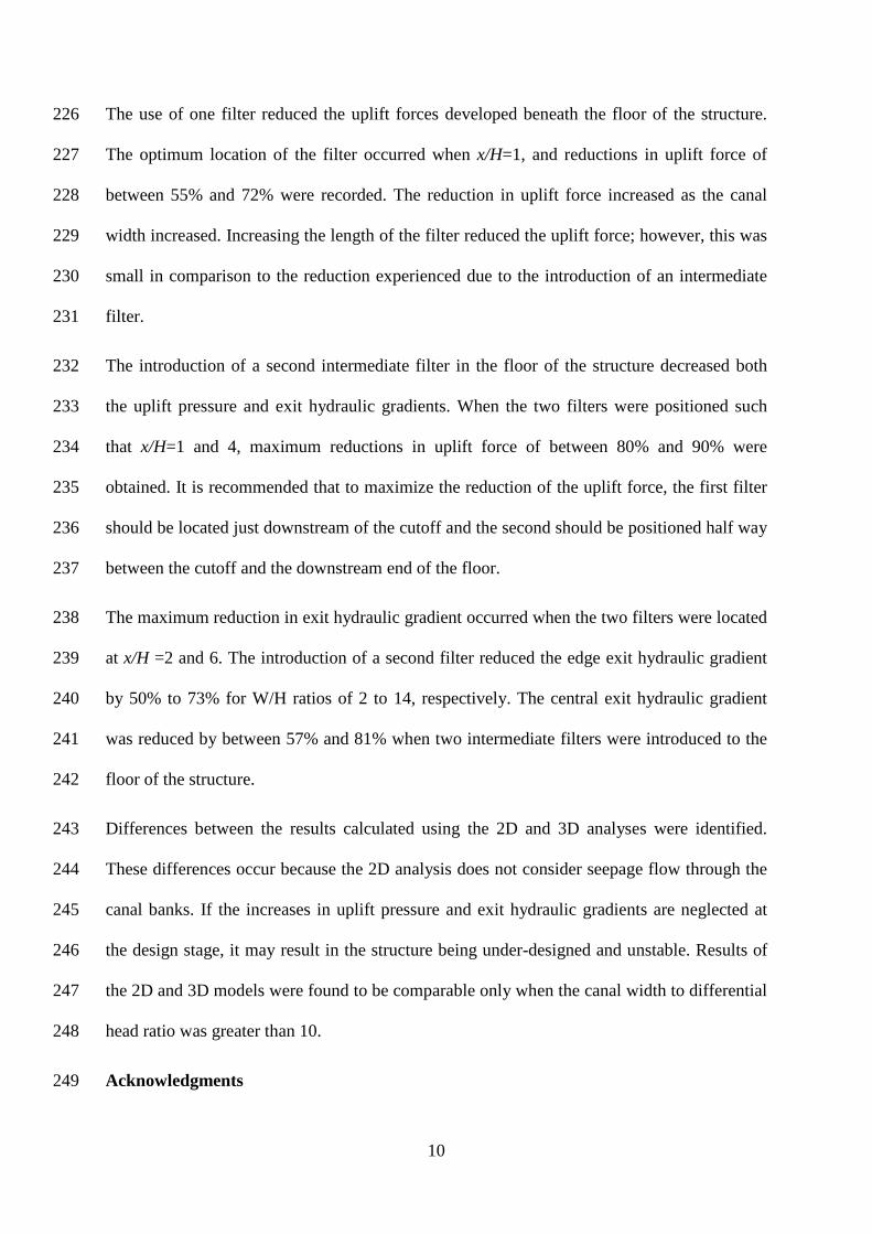
The use of one filter reduced the uplift forces developed beneath the floor of the structure. 226
The optimum location of the filter occurred when x/H=1, and reductions in uplift force of 227
between 55% and 72% were recorded. The reduction in uplift force increased as the canal 228
width increased. Increasing the length of the filter reduced the uplift force; however, this was 229
small in comparison to the reduction experienced due to the introduction of an intermediate 230
filter. 231
The introduction of a second intermediate filter in the floor of the structure decreased both 232
the uplift pressure and exit hydraulic gradients. When the two filters were positioned such 233
that x/H=1 and 4, maximum reductions in uplift force of between 80% and 90% were 234
obtained. It is recommended that to maximize the reduction of the uplift force, the first filter 235
should be located just downstream of the cutoff and the second should be positioned half way 236
between the cutoff and the downstream end of the floor. 237
The maximum reduction in exit hydraulic gradient occurred when the two filters were located 238
at x/H =2 and 6. The introduction of a second filter reduced the edge exit hydraulic gradient 239
by 50% to 73% for W/H ratios of 2 to 14, respectively. The central exit hydraulic gradient 240
was reduced by between 57% and 81% when two intermediate filters were introduced to the 241
floor of the structure. 242
Differences between the results calculated using the 2D and 3D analyses were identified. 243
These differences occur because the 2D analysis does not consider seepage flow through the 244
canal banks. If the increases in uplift pressure and exit hydraulic gradients are neglected at 245
the design stage, it may result in the structure being under-designed and unstable. Results of 246
the 2D and 3D models were found to be comparable only when the canal width to differential 247
head ratio was greater than 10. 248
Acknowledgments 249

11
The authors would like to thank the anonymous reviewers for their constructive comments 250
that helped improve the manuscript of this paper. 251
References 252
1. Ahmed, A. A. (2008). "Saturated-unsaturated flow through leaky dams." J. Geotech. 253
Geoenviron. Eng., 134(10), 1564-1568. 254
2. Ahmed, A. A. (2009). "Stochastic analysis of free surface flow through earth dams." 255
Comput. Geotech., 36(7), 1186-1190. 256
3. Ahmed, A. A. (2011). "Design of hydraulic structures considering different sheetpile 257
configurations and flow through canal banks." Comput. Geotech., 38(4), 559-565. 258
4. Ahmed A A, Soliman A M, Bazaraa A S (2007) 3-D steady analysis of leaky hydraulic 259
structures: 1. Leaky sheetpiles. J of Eng. Appl. Sci. 54(2): 141-157. 260
5. Ahmed, A. A., and Bazaraa, A. S. (2009). "Three-dimensional analysis of seepage 261
below and around hydraulic structures." J. of Hydrol. Eng., 14(3), 243-247. 262
6. Chawla, A S (1975). “Stability of structures with intermediate filters.” J Hydraul. Div., 263
101(2), 223-241. 264
7. Elganainy M (1986). “Flow underneath a pair of structures with intermediate filters on 265
a drained stratum.” Appl. Math. Model., 10(6), 394-400. 266
8. Farouk, M I, and Smith I M (2000). “Design of hydraulic structures with two 267
intermediate filters.” Appl. Math. Model., 24, 779-794. 268
9. Griffiths, D. V., and Fenton, G. A. (1997). "Three-dimensional seepage through 269
spatially random soil." J. Geotech. Geoenviron. Eng., 123(2), 153-160. 270
10.Hathoot H M (1986) Seepage beneath a concrete dam with a downstream filter. Appl. 271
Math. Model. 10(2), 129-132. 272
11.Kumar A, Singh B, and Chawla A S (1986). “Design of structures with intermediate 273
filters.” J Hydraul. Eng. 112(3), 206-219. 274
12.Salem, A S, and Ghazaw Y. (2001). “Stability of two consecutive floors with 275
intermediate filters.” J Hydraul. Res., 39(5), 549-555. 276
13.van Genuchten M Th (1980). “A closed-form equation for predicting the hydraulic 277
conductivity of unsaturated soils.” Soil Sci. Soc. Am. J., 1980, 44, 892-898. 278
279

12
Figures Captions 280 281
Fig 1. 3D view and cross section of the configuration studied 282
Fig 2. Free surface at different sections perpendicular to the canal centerline (W/H=10) 283
Fig 3. Effect of filter location on the downstream uplift force for different widths of the canal. 284 The uplift force is normalized to the case of no filter in place. 285
Fig 4 Change of the exit gradient along the canal width. The exit hydraulic gradient is 286 normalized to the case of no filter in place (W/H=10). 287
Fig. 5. Effect of filter location on the exit hydraulic gradient for different widths of the canal. 288 The exit gradient is normalized to the case of no filter in place. 289
Fig. 6. Effect of filter length on uplift force. The uplift force is normalized to the case of no 290 filter in place. 291
Fig. 7. Effect of introducing a second filter on uplift force developed beneath the floor of the 292 structure. 293
Fig. 8. Reduction in uplift force for various filters locations and varying floor length. 294
Fig.9. Reduction in the exit hydraulic gradient for one- and two-filter scenarios (one filter 295 x/H=6; two filters x/H= 2& 6). 296

Fig 1
Cross sectionn through the c
canal
3D vie
L
ew
X

Fig 2
4
5
6
7
0 5 10 15 20 25 30
Z (m
)
Y (m)
10 m upstream the floor
Just upstream the floor
Just downstream the floor
10 m downstream the floor
Downstream
Upstream

Fig 3
0.00
0.10
0.20
0.30
0.40
0.50
0.60
0.70
0.80
0 1 2 3 4 5 6Upl
ift fo
rce
norm
alize
d to
the
case
of n
o fil
ter
Ratio of filter distance downstream of sheet pile to the differential head x/H
2D W/H=2W/H=4 W/H=6W/H=8 W/H=10W/H=12 W/H=14

Fig 4
0.00
0.10
0.20
0.30
0.40
0.50
0.60
0.70
0 0.2 0.4 0.6 0.8 1
Exit
grad
ient
nor
mal
ized
to th
e ex
it gr
adie
nt
for c
ase
of n
o fil
ter
Ratio of canal width
x/H=1x/H=3x/H=5x/H=6
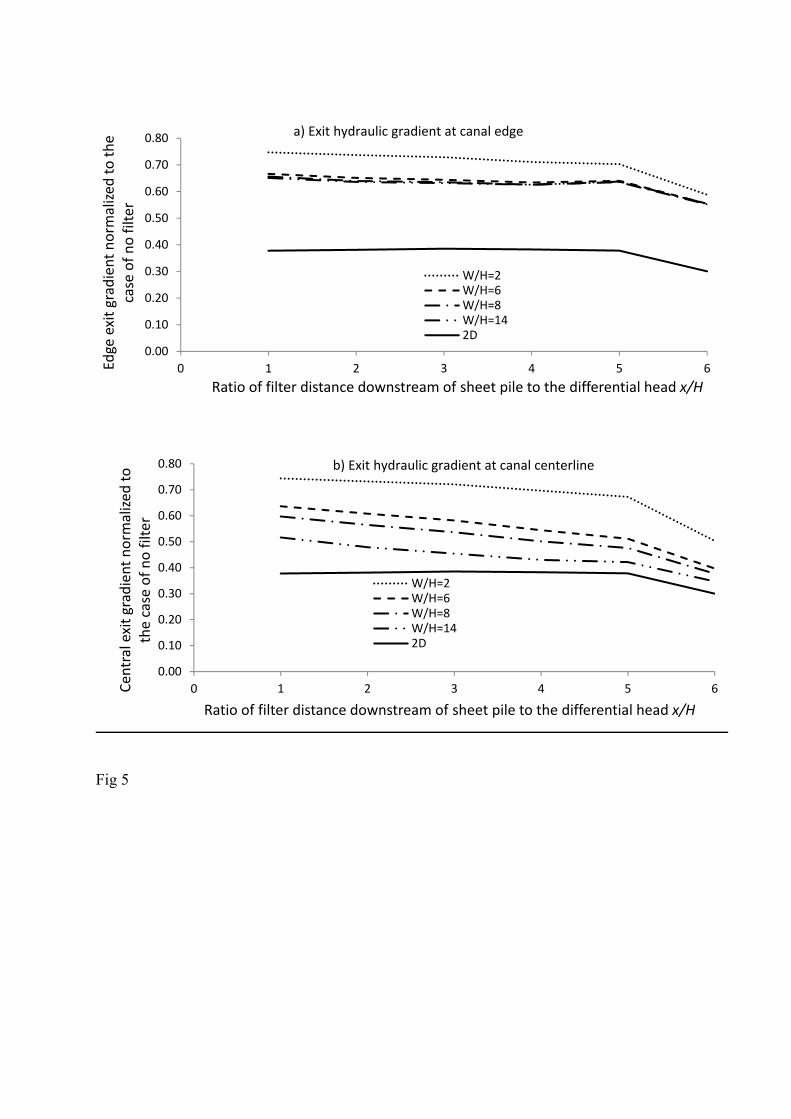
Fig 5
0.00
0.10
0.20
0.30
0.40
0.50
0.60
0.70
0.80
0 1 2 3 4 5 6Edge
exi
t gra
dien
t nor
mal
ized
to th
e ca
se o
f no
filte
r
Ratio of filter distance downstream of sheet pile to the differential head x/H
a) Exit hydraulic gradient at canal edge
W/H=2W/H=6W/H=8W/H=142D
0.00
0.10
0.20
0.30
0.40
0.50
0.60
0.70
0.80
0 1 2 3 4 5 6Cent
ral e
xit g
radi
ent n
orm
alize
d to
th
e ca
se o
f no
filte
r
Ratio of filter distance downstream of sheet pile to the differential head x/H
b) Exit hydraulic gradient at canal centerline
W/H=2W/H=6W/H=8W/H=142D


Fig 6
0
0.05
0.1
0.15
0.2
0.25
0.3
0.35
2D: 1mfilter
2D: 2mfilter
W/H=8;1m filter
W/H=8;2m Filter
W/H=12;1m filter
W/H=12;2m filter
Upl
ift fo
rce
norm
alize
d to
the
case
of n
o fil
ter

Fig. 7
0.00
0.05
0.10
0.15
0.20
0.25
0.30
0.35
0.40
0.45
Upl
ift fo
rce
norm
alize
d to
the
case
of n
o fil
ter
Filter location
2DW/H=2W/H=4W/H=6W/H=8W/H=10W/H=12W/H=14

Fig. 8
0.00
0.05
0.10
0.15
0.20
0.25
0.30
0.35
0.40
Upl
ift fo
rce
norm
alize
d to
the
case
of
no fi
lter
Filters locations
Floor/head ratio= 16Floor/head ratio= 20Floor/head ratio= 24

Fig 9
0.00
0.10
0.20
0.30
0.40
0.50
0.60
0.70
Edge
Exi
t Gra
dien
t nor
mal
ized
to th
e ca
se o
f no
filte
r
1 filter 2 filters
0.00
0.10
0.20
0.30
0.40
0.50
0.60
Cent
ral e
xit
grad
ient
nor
mal
ized
to th
e ca
se o
f no
filte
r
1 filter 2 filters
b) At canal centerline
a) At canal edge
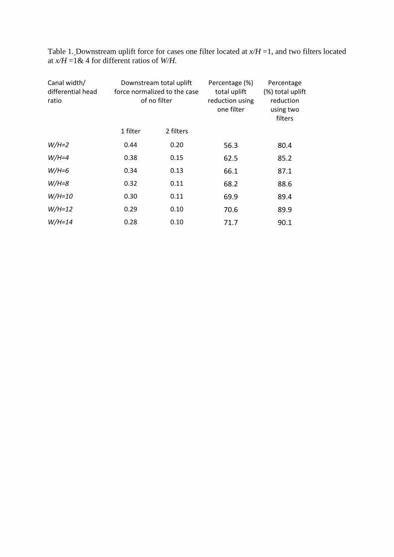
Table 1. Downstream uplift force for cases one filter located at x/H =1, and two filters located at x/H =1& 4 for different ratios of W/H.
Canal width/ differential head ratio
Downstream total uplift force normalized to the case
of no filter
Percentage (%) total uplift
reduction using one filter
Percentage (%) total uplift
reduction using two
filters
1 filter 2 filters
W/H=2 0.44 0.20 56.3 80.4 W/H=4 0.38 0.15 62.5 85.2 W/H=6 0.34 0.13 66.1 87.1 W/H=8 0.32 0.11 68.2 88.6 W/H=10 0.30 0.11 69.9 89.4 W/H=12 0.29 0.10 70.6 89.9 W/H=14 0.28 0.10 71.7 90.1
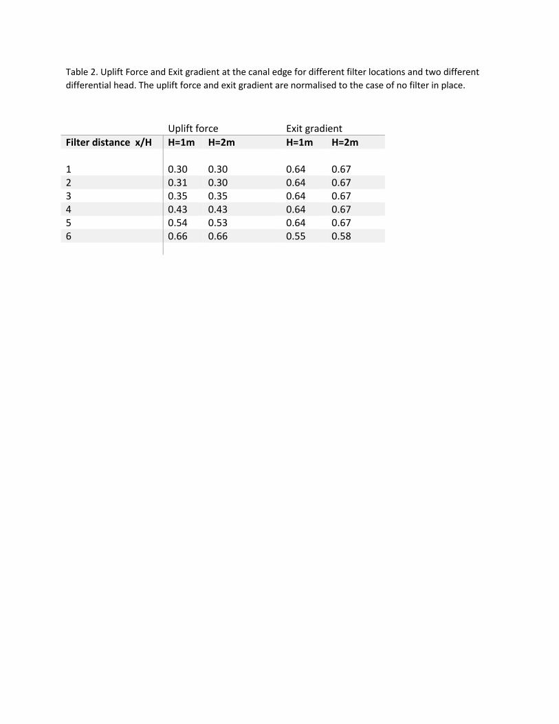
Table 2. Uplift Force and Exit gradient at the canal edge for different filter locations and two different differential head. The uplift force and exit gradient are normalised to the case of no filter in place.
Uplift force Exit gradient Filter distance x/H H=1m H=2m H=1m H=2m 1
0.30
0.30
0.64
0.67
2 0.31 0.30 0.64 0.67 3 0.35 0.35 0.64 0.67 4 0.43 0.43 0.64 0.67 5 0.54 0.53 0.64 0.67 6 0.66 0.66 0.55 0.58