Embed Size (px)
Citation preview

Title page
Alcatel-Lucent 1626 Light Manager
1626LM Optical Network Design Platform (ONDP) | Release 7.0
User Guide
3AL-75223-RAAA-TQZZA
Issue 4 | March 2013

Legal notice
Legal notice
Alcatel, Lucent, Alcatel-Lucent and the Alcatel-Lucent logo are trademarks of Alcatel-Lucent. All other trademarks are the property of their respective
owners.
The information presented is subject to change without notice. Alcatel-Lucent assumes no responsibility for inaccuracies contained herein.
Copyright © 2013 Alcatel-Lucent. All rights reserved.
Not to be used or disclosed except in accordance with applicable agreements.
Security Statement
In rare instances, unauthorized individuals make connections to the telecommunications network through the use of remote access features. In such an event,
applicable tariffs require that the customer pay all network charges for traffic. Alcatel-Lucent cannot be responsible for such charges and will not make any
allowances or give any credit for charges that result from unauthorized access.
Limited Warranty
For terms and conditions of sale, contact your Alcatel-Lucent Account Team.
Ordering information
The ordering number for this product guide is 3AL-75223-RAAA-TQZZA.
To order Alcatel-Lucent documents, contact your local sales representatives or use Online Customer Support (OLCS) https://support.lucent.com
(http://support.alcatel-lucent.com).

Contents
About this document
Purpose ........................................................................................................................................................................................... xixxix
Intended audience ...................................................................................................................................................................... xixxix
How to use this information product ................................................................................................................................... xixxix
Related documents ...................................................................................................................................................................... xxxx
Related training ........................................................................................................................................................................... xxixxi
Technical support ....................................................................................................................................................................... xxixxi
How to order ................................................................................................................................................................................ xxixxi
Quality policy ............................................................................................................................................................................. xxiixxii
How to comment ....................................................................................................................................................................... xxiixxii
1 Introduction
Overview ...................................................................................................................................................................................... 1-11-1
Features ......................................................................................................................................................................................... 1-21-2
Functionality ............................................................................................................................................................................... 1-81-8
The ONDP Interface ................................................................................................................................................................ 1-91-9
2 Installation and Startup
Overview ...................................................................................................................................................................................... 2-12-1
Installation Requirements ...................................................................................................................................................... 2-22-2
Installer Welcome Window ................................................................................................................................................... 2-42-4
InstallShield Wizard Window ............................................................................................................................................... 2-62-6
Install ONDP .............................................................................................................................................................................. 2-72-7
Update ONDP Version .......................................................................................................................................................... 2-102-10
Uninstall ONDP ...................................................................................................................................................................... 2-122-12
....................................................................................................................................................................................................................................
1626LM ONDP R7.0
3AL-75223-RAAA-TQZZA Release 7.0
Issue 4 March 2013
iii

Launch ONDP ......................................................................................................................................................................... 2-132-13
Close ONDP ............................................................................................................................................................................. 2-142-14
3 ONDP User Interface
Overview ...................................................................................................................................................................................... 3-13-1
Main Menu and Toolbar ......................................................................................................................................................... 3-23-2
Map Legend .............................................................................................................................................................................. 3-133-13
4 Design Inputs
Overview ...................................................................................................................................................................................... 4-14-1
Section 1: Starting the Design
Overview ...................................................................................................................................................................................... 4-34-3
Design Inputs .............................................................................................................................................................................. 4-44-4
Incremental Design .................................................................................................................................................................. 4-64-6
Create a New Project ............................................................................................................................................................... 4-94-9
Open an Existing Project (.ondp file) .............................................................................................................................. 4-114-11
Section 2: Sites
Overview ................................................................................................................................................................................... 4-134-13
Sites ............................................................................................................................................................................................ 4-144-14
Create Sites ............................................................................................................................................................................... 4-244-24
Edit NE Configuration .......................................................................................................................................................... 4-264-26
Edit Site Parameters .............................................................................................................................................................. 4-284-28
Delete Sites ............................................................................................................................................................................... 4-294-29
Section 3: ILAs
Overview ................................................................................................................................................................................... 4-304-30
ILAs ............................................................................................................................................................................................. 4-314-31
Change ILA Site Name ........................................................................................................................................................ 4-344-34
Contents
....................................................................................................................................................................................................................................
....................................................................................................................................................................................................................................
iv 1626LM ONDP R7.0
3AL-75223-RAAA-TQZZA Release 7.0
Issue 4 March 2013

Section 4: Links and Spans
Overview ................................................................................................................................................................................... 4-364-36
Links and Spans ...................................................................................................................................................................... 4-374-37
Create Links and Spans ........................................................................................................................................................ 4-464-46
Edit Links and Spans ............................................................................................................................................................. 4-474-47
Add Spans to Links ................................................................................................................................................................ 4-484-48
Change Span Parameters and Copy to a New Span ................................................................................................... 4-504-50
Merge Spans ............................................................................................................................................................................. 4-524-52
Delete Links and Spans ........................................................................................................................................................ 4-544-54
Identify a Link on the Map ................................................................................................................................................. 4-554-55
Section 5: Relations and Services
Overview ................................................................................................................................................................................... 4-564-56
Relations and Services .......................................................................................................................................................... 4-574-57
Create a Relation .................................................................................................................................................................... 4-784-78
Edit Relations and Services ................................................................................................................................................ 4-794-79
Create Services ........................................................................................................................................................................ 4-804-80
Change Service Parameters and Copy to a New Service ......................................................................................... 4-824-82
Delete Relations and Services ........................................................................................................................................... 4-844-84
Identify a Relation on the Map .......................................................................................................................................... 4-854-85
Edit Spatial and Spectral Constraints .............................................................................................................................. 4-864-86
Section 6: Optical Subsets
Overview ................................................................................................................................................................................... 4-884-88
Optical Subsets ........................................................................................................................................................................ 4-894-89
Create Optical Subset ............................................................................................................................................................ 4-974-97
Section 7: Shared Risk Groups (SRGs) and Failure Scope
Overview ................................................................................................................................................................................... 4-984-98
Contents
....................................................................................................................................................................................................................................
....................................................................................................................................................................................................................................
1626LM ONDP R7.0
3AL-75223-RAAA-TQZZA Release 7.0
Issue 4 March 2013
v

Shared Risk Groups (SRGs) ............................................................................................................................................... 4-994-99
Failures Scope ....................................................................................................................................................................... 4-1054-105
Create an SRG ....................................................................................................................................................................... 4-1094-109
Include/Exclude Links/Sites in SRGs ........................................................................................................................... 4-1104-110
Delete SRGs ........................................................................................................................................................................... 4-1114-111
Edit a Failures Scope .......................................................................................................................................................... 4-1124-112
Section 8: Design Parameters
Overview ................................................................................................................................................................................. 4-1144-114
Design Parameters ............................................................................................................................................................... 4-1154-115
WDM Layer Design Parameters .................................................................................................................................... 4-1174-117
Traffic Setting Design Parameters ................................................................................................................................. 4-1224-122
Set Design Parameters ....................................................................................................................................................... 4-1254-125
5 Run the Network Design
Overview ...................................................................................................................................................................................... 5-15-1
The Network Design ................................................................................................................................................................ 5-25-2
Run the Full Network Design ............................................................................................................................................... 5-45-4
Run Partial Network Designs for Links ........................................................................................................................... 5-55-5
6 Design Results
Overview ...................................................................................................................................................................................... 6-16-1
Design Results and Reports .................................................................................................................................................. 6-26-2
Show/Tune Selected Links Design .................................................................................................................................... 6-36-3
Show Selected Links Physical Diagnostics ..................................................................................................................... 6-66-6
Show Selected Links Real-Time Fast Feasibility Criteria ....................................................................................... 6-156-15
Show Graphical Statistics .................................................................................................................................................... 6-176-17
Show Network Statistics ...................................................................................................................................................... 6-216-21
Show Failures Report ............................................................................................................................................................ 6-246-24
Contents
....................................................................................................................................................................................................................................
....................................................................................................................................................................................................................................
vi 1626LM ONDP R7.0
3AL-75223-RAAA-TQZZA Release 7.0
Issue 4 March 2013

Show GMRE Audit Logs ..................................................................................................................................................... 6-316-31
Show Traffic Design Logs .................................................................................................................................................. 6-346-34
Show Errors Report ............................................................................................................................................................... 6-356-35
Show Bill of Material ........................................................................................................................................................... 6-376-37
Show Bill of Material (multi-step) ................................................................................................................................... 6-386-38
Show Sites/Part List .............................................................................................................................................................. 6-396-39
Show Equipment View ......................................................................................................................................................... 6-406-40
Show Line View ...................................................................................................................................................................... 6-416-41
Export Design Results Excel Report ............................................................................................................................... 6-456-45
Export BoM .............................................................................................................................................................................. 6-716-71
7 Network Analysis: Audit and Upgrade
Overview ...................................................................................................................................................................................... 7-17-1
Network Configuration in ONDP ...................................................................................................................................... 7-27-2
Network Analysis: Audit ........................................................................................................................................................ 7-47-4
Network Analysis: Upgrade .................................................................................................................................................. 7-77-7
Audit: Failure and Restoration Analysis — GMRE Simulator ................................................................................ 7-97-9
8 Modifications for ONDP Design
Overview ...................................................................................................................................................................................... 8-18-1
Manual Shelf Modifications for ONDP Designs - Concepts .................................................................................... 8-28-2
Manual Shelf Modifications for ONDP Designs - Interface ..................................................................................... 8-78-7
Manual Management of Ports on Concentrators - Concepts .................................................................................. 8-158-15
Manual Management of Ports on Concentrators - Interface ................................................................................... 8-168-16
9 Map Management
Overview ...................................................................................................................................................................................... 9-19-1
Map Generation ......................................................................................................................................................................... 9-29-2
Launch the Map Generation Application ......................................................................................................................... 9-79-7
Contents
....................................................................................................................................................................................................................................
....................................................................................................................................................................................................................................
1626LM ONDP R7.0
3AL-75223-RAAA-TQZZA Release 7.0
Issue 4 March 2013
vii

Generate a Background Map ................................................................................................................................................ 9-89-8
Glossary
Index
Contents
....................................................................................................................................................................................................................................
....................................................................................................................................................................................................................................
viii 1626LM ONDP R7.0
3AL-75223-RAAA-TQZZA Release 7.0
Issue 4 March 2013

List of tables
2-1 Minimum PC Requirements .................................................................................................................................. 2-22-2
3-1 File menu descriptions ............................................................................................................................................. 3-23-2
3-2 Edit menu descriptions ............................................................................................................................................ 3-33-3
3-3 Display menu descriptions ..................................................................................................................................... 3-43-4
3-4 Inputs menu descriptions ........................................................................................................................................ 3-53-5
3-5 Design menu descriptions ....................................................................................................................................... 3-73-7
3-6 Reports menu descriptions ..................................................................................................................................... 3-83-8
3-7 Tools menu descriptions ....................................................................................................................................... 3-103-10
3-8 Misc menu descriptions ........................................................................................................................................ 3-103-10
3-9 Toolbar icon descriptions ..................................................................................................................................... 3-113-11
3-10 Site icons .................................................................................................................................................................... 3-133-13
3-11 Traffic Icons .............................................................................................................................................................. 3-153-15
3-12 Topology Map pop-up menu ............................................................................................................................... 3-153-15
3-13 Site pop-up menu .................................................................................................................................................... 3-163-16
3-14 Link pop-up menu ................................................................................................................................................... 3-173-17
3-15 Relation pop-up menu ........................................................................................................................................... 3-193-19
4-1 Edit menu Incremental Design descriptions .................................................................................................... 4-64-6
4-2 Types of sites ............................................................................................................................................................ 4-144-14
4-3 Edit NE window ...................................................................................................................................................... 4-194-19
4-4 Edit Sites window pop-up menu ........................................................................................................................ 4-214-21
4-5 Site parameters ......................................................................................................................................................... 4-214-21
4-6 Edit Sites window button actions ...................................................................................................................... 4-234-23
4-7 ILA parameters ......................................................................................................................................................... 4-324-32
....................................................................................................................................................................................................................................
1626LM ONDP R7.0
3AL-75223-RAAA-TQZZA Release 7.0
Issue 4 March 2013
ix

4-8 Edit ILAs window pop-up menu ....................................................................................................................... 4-334-33
4-9 Links table pop-up menu ..................................................................................................................................... 4-384-38
4-10 Links parameters ..................................................................................................................................................... 4-394-39
4-11 Mixed fiber types with DSF length restriction ............................................................................................. 4-414-41
4-12 Links table button actions .................................................................................................................................... 4-414-41
4-13 Spans table pop-up menu .................................................................................................................................... 4-424-42
4-14 Span parameters ....................................................................................................................................................... 4-434-43
4-15 Spans table button actions .................................................................................................................................... 4-454-45
4-16 Relations table pop-up menu ............................................................................................................................. 4-594-59
4-17 Working [W] Constraints pop up menu ........................................................................................................... 4-604-60
4-18 Protecting [P] Constraints pop up menu ......................................................................................................... 4-614-61
4-19 Relations parameters .............................................................................................................................................. 4-624-62
4-20 Relations table button actions ............................................................................................................................. 4-644-64
4-21 Services table pop-up menu ............................................................................................................................... 4-654-65
4-22 Line View... pop up menu .................................................................................................................................... 4-674-67
4-23 Topo Highlight...pop up menu ............................................................................................................................ 4-684-68
4-24 Working [W] Constraints pop up menu ........................................................................................................... 4-684-68
4-25 Protecting [P] Constraints pop up menu ......................................................................................................... 4-694-69
4-26 Services parameters ................................................................................................................................................ 4-704-70
4-27 Services table button actions ............................................................................................................................... 4-734-73
4-28 Optical Subset parameters .................................................................................................................................... 4-904-90
4-29 Edit Optical Subsets pop-up menu .................................................................................................................. 4-914-91
4-30 Optical Subsets table button actions ................................................................................................................ 4-924-92
4-31 Included menu ....................................................................................................................................................... 4-1024-102
4-32 Excluded menu ...................................................................................................................................................... 4-1034-103
4-33 Included menu ....................................................................................................................................................... 4-1064-106
4-34 Excluded menu ...................................................................................................................................................... 4-1074-107
List of tables
....................................................................................................................................................................................................................................
....................................................................................................................................................................................................................................
x 1626LM ONDP R7.0
3AL-75223-RAAA-TQZZA Release 7.0
Issue 4 March 2013

5-1 Run Full Design icon coloration .......................................................................................................................... 5-35-3
6-1 Optical design parameters ...................................................................................................................................... 6-46-4
6-2 List of reported network design errors ............................................................................................................ 6-366-36
8-1 Board modification status description ................................................................................................................ 8-38-3
8-2 File menu commands and descriptions .............................................................................................................. 8-88-8
8-3 Edit menu commands and descriptions ............................................................................................................. 8-88-8
8-4 Display menu commands and descriptions ...................................................................................................... 8-98-9
8-5 NE level menu options .......................................................................................................................................... 8-118-11
8-6 Rack level menu options ...................................................................................................................................... 8-128-12
8-7 SubRack level menu options ............................................................................................................................... 8-128-12
8-8 Ports View pop-up menu ...................................................................................................................................... 8-188-18
8-9 Ports View window field descriptions ............................................................................................................. 8-198-19
List of tables
....................................................................................................................................................................................................................................
....................................................................................................................................................................................................................................
1626LM ONDP R7.0
3AL-75223-RAAA-TQZZA Release 7.0
Issue 4 March 2013
xi

List of tables
....................................................................................................................................................................................................................................
....................................................................................................................................................................................................................................
xii 1626LM ONDP R7.0
3AL-75223-RAAA-TQZZA Release 7.0
Issue 4 March 2013

List of figures
1-1 The ONDP GUI .......................................................................................................................................................... 1-91-9
2-1 Installer Welcome window ..................................................................................................................................... 2-42-4
2-2 InstallShield Wizard window ................................................................................................................................ 2-62-6
3-1 File menu ...................................................................................................................................................................... 3-23-2
3-2 Edit menu ...................................................................................................................................................................... 3-33-3
3-3 Display menu .............................................................................................................................................................. 3-43-4
3-4 Inputs menu ................................................................................................................................................................. 3-53-5
3-5 Design menu ................................................................................................................................................................ 3-73-7
3-6 Reports menu .............................................................................................................................................................. 3-83-8
3-7 Misc. menu ................................................................................................................................................................ 3-103-10
3-8 Misc. menu ................................................................................................................................................................ 3-103-10
3-9 Help menu .................................................................................................................................................................. 3-103-10
3-10 Help window ............................................................................................................................................................. 3-113-11
3-11 Edge tooltip ............................................................................................................................................................... 3-143-14
3-12 Topology Map Pop menu ..................................................................................................................................... 3-153-15
3-13 Site pop-up menu .................................................................................................................................................... 3-163-16
3-14 Link pop-up menu ................................................................................................................................................... 3-173-17
3-15 Relation pop-up menu ........................................................................................................................................... 3-193-19
4-1 Init [ONDP] window ................................................................................................................................................ 4-54-5
4-2 Encrypt ONDP file on saving checkbox ........................................................................................................... 4-54-5
4-3 Edit menu Incremental Design options ............................................................................................................. 4-64-6
4-4 Step Slider window ................................................................................................................................................... 4-74-7
4-5 Edit NE window ...................................................................................................................................................... 4-194-19
....................................................................................................................................................................................................................................
1626LM ONDP R7.0
3AL-75223-RAAA-TQZZA Release 7.0
Issue 4 March 2013
xiii

4-6 Edit Sites window ................................................................................................................................................... 4-204-20
4-7 Edit Sites window pop-up menu ........................................................................................................................ 4-214-21
4-8 Edit ILAs window ................................................................................................................................................... 4-314-31
4-9 Edit ILAs window pop-up menu ....................................................................................................................... 4-334-33
4-10 Edit Spans window ................................................................................................................................................. 4-374-37
4-11 Links table pop-up menu ...................................................................................................................................... 4-384-38
4-12 Spans table pop-up menu ..................................................................................................................................... 4-424-42
4-13 Edit Services window ............................................................................................................................................ 4-584-58
4-14 Relations table pop-up menu .............................................................................................................................. 4-584-58
4-15 Topo Highlight... pop up menu .......................................................................................................................... 4-604-60
4-16 Working [W] Constraints pop up menu ........................................................................................................... 4-604-60
4-17 Protecting [P] Constraints pop up menu ......................................................................................................... 4-614-61
4-18 Services table pop-up menu ................................................................................................................................ 4-654-65
4-19 Line View... pop up menu .................................................................................................................................... 4-674-67
4-20 Topo Highlight... pop up menu .......................................................................................................................... 4-684-68
4-21 Working [W] Constraints pop up menu ........................................................................................................... 4-684-68
4-22 Protecting [P] Constraints pop up menu ......................................................................................................... 4-694-69
4-23 Edit Spectral Constraint window ....................................................................................................................... 4-754-75
4-24 Set Mutual Disjointness window ....................................................................................................................... 4-774-77
4-25 Edit Optical Subsets window .............................................................................................................................. 4-894-89
4-26 Edit Optical Subsets window pop-up menu .................................................................................................. 4-914-91
4-27 Edit Subset Mask window ................................................................................................................................... 4-954-95
4-28 Edit SRGs window Contents tab ..................................................................................................................... 4-1004-100
4-29 Edit SRGs window Parameters tab ................................................................................................................ 4-1014-101
4-30 SRG menu ............................................................................................................................................................... 4-1024-102
4-31 Included menu ....................................................................................................................................................... 4-1024-102
4-32 Excluded menu ...................................................................................................................................................... 4-1034-103
List of figures
....................................................................................................................................................................................................................................
....................................................................................................................................................................................................................................
xiv 1626LM ONDP R7.0
3AL-75223-RAAA-TQZZA Release 7.0
Issue 4 March 2013

4-33 Transfer buttons ..................................................................................................................................................... 4-1044-104
4-34 Included menu ....................................................................................................................................................... 4-1064-106
4-35 Excluded menu ...................................................................................................................................................... 4-1074-107
4-36 Transfer buttons ..................................................................................................................................................... 4-1084-108
4-37 Set Design Parameters window ....................................................................................................................... 4-1164-116
4-38 WDM Layer tab .................................................................................................................................................... 4-1174-117
4-39 Traffic Setting tab ................................................................................................................................................. 4-1224-122
6-1 Edit route optical design window ........................................................................................................................ 6-46-4
6-2 Path Feasibility window .......................................................................................................................................... 6-76-7
6-3 Optical design window ............................................................................................................................................ 6-86-8
6-4 Dispersion Map window ......................................................................................................................................... 6-96-9
6-5 Show Selected Links Physical Diagnostics pop-up menu ....................................................................... 6-106-10
6-6 Chart Properties window - Title tab ................................................................................................................. 6-126-12
6-7 Chart Properties window - Plot tab ................................................................................................................... 6-136-13
6-8 Chart Properties window - Other tab ............................................................................................................... 6-146-14
6-9 Real-Time Fast Feasibility Criteria – 10G ..................................................................................................... 6-166-16
6-10 Real-Time Fast Feasibility Criteria – Mixed 10G/40G ............................................................................. 6-166-16
6-11 Spans Count graphical statistics example ...................................................................................................... 6-196-19
6-12 Access Load graphical statistics example ...................................................................................................... 6-206-20
6-13 Network Statistics report - General Statistics tab ........................................................................................ 6-226-22
6-14 Network Statistics report - Statistics on Step tab ........................................................................................ 6-236-23
6-15 Service Summary button ...................................................................................................................................... 6-246-24
6-16 Failures Report, Services tab .............................................................................................................................. 6-266-26
6-17 Failures Report, Scenarios tab ............................................................................................................................ 6-276-27
6-18 Failures Report, Filter tab .................................................................................................................................... 6-296-29
6-19 GMRE Audit Logs report — determining success of GMPLS dimensioning .................................. 6-326-32
6-20 GMRE Audit Logs report — evaluate tolerance of GMPLS restoration dimensioning ................ 6-336-33
List of figures
....................................................................................................................................................................................................................................
....................................................................................................................................................................................................................................
1626LM ONDP R7.0
3AL-75223-RAAA-TQZZA Release 7.0
Issue 4 March 2013
xv

6-21 Traffic design logs report ..................................................................................................................................... 6-346-34
6-22 List Errors report ..................................................................................................................................................... 6-356-35
6-23 Bill of Material report ............................................................................................................................................ 6-376-37
6-24 Incremental Bill of Material report ................................................................................................................... 6-386-38
6-25 Part List report .......................................................................................................................................................... 6-396-39
6-26 Edit Equipments report ......................................................................................................................................... 6-406-40
6-27 Show Line View Display options ...................................................................................................................... 6-426-42
6-28 Line View (full spectrum) report ....................................................................................................................... 6-436-43
6-29 Line View (optimized) report ............................................................................................................................. 6-446-44
6-30 Excel Export Filtering window .......................................................................................................................... 6-456-45
6-31 Descriptive Sheet tab ............................................................................................................................................. 6-486-48
6-32 Map tab ....................................................................................................................................................................... 6-496-49
6-33 Sites tab ....................................................................................................................................................................... 6-506-50
6-34 Links tab ..................................................................................................................................................................... 6-516-51
6-35 Relations tab .............................................................................................................................................................. 6-526-52
6-36 BOM tab ..................................................................................................................................................................... 6-536-53
6-37 Part List Sites tab .................................................................................................................................................... 6-546-54
6-38 Design Service Summary tab .............................................................................................................................. 6-556-55
6-39 Restoration tab ......................................................................................................................................................... 6-566-56
6-40 Graph Statistics tab ................................................................................................................................................. 6-576-57
6-41 Inter-NE Links, LT and Node tab ...................................................................................................................... 6-586-58
6-42 NE Parameters tab .................................................................................................................................................. 6-596-59
6-43 Subsets tab ................................................................................................................................................................. 6-606-60
6-44 GMPLS Link Optical Parameters tab .............................................................................................................. 6-616-61
6-45 GMPLS AddDropType per Site ......................................................................................................................... 6-626-62
6-46 SRG tab ....................................................................................................................................................................... 6-636-63
6-47 Network Design Logs tab .................................................................................................................................... 6-646-64
List of figures
....................................................................................................................................................................................................................................
....................................................................................................................................................................................................................................
xvi 1626LM ONDP R7.0
3AL-75223-RAAA-TQZZA Release 7.0
Issue 4 March 2013

6-48 OSNR NLP tab ......................................................................................................................................................... 6-656-65
6-49 CD tab ......................................................................................................................................................................... 6-666-66
6-50 PL Site X tab ............................................................................................................................................................. 6-676-67
6-51 SP Site-X Site-X tab ............................................................................................................................................... 6-686-68
6-52 Ser Site-X Site-X ..................................................................................................................................................... 6-696-69
6-53 DSF Mask 2 Forghieri grids tab ........................................................................................................................ 6-706-70
6-54 Export BoM report .................................................................................................................................................. 6-726-72
8-1 Add/Drop boards directions and sides ............................................................................................................... 8-48-4
8-2 Edit Equipments window ........................................................................................................................................ 8-78-7
8-3 Edit Equipments window File menu .................................................................................................................. 8-88-8
8-4 Edit Equipments window Edit menu .................................................................................................................. 8-88-8
8-5 Edit Equipments window Display menu ........................................................................................................... 8-98-9
8-6 Left navigation tree ................................................................................................................................................ 8-108-10
8-7 NE level menu .......................................................................................................................................................... 8-118-11
8-8 Rack level menu ...................................................................................................................................................... 8-118-11
8-9 SubRack level menu ............................................................................................................................................... 8-128-12
8-10 Edit Equipments window Main panel ............................................................................................................. 8-138-13
8-11 Edit Equipments window menu - all boards except concentrators ....................................................... 8-138-13
8-12 Edit Equipments window menu - concentrators .......................................................................................... 8-148-14
8-13 Ports View window - Example 1 ....................................................................................................................... 8-168-16
8-14 Ports View window - Example 2 ....................................................................................................................... 8-178-17
8-15 Ports View pop-up menu ...................................................................................................................................... 8-188-18
9-1 Map Calibration - Step 1 window ....................................................................................................................... 9-39-3
9-2 Map Calibration - Step 2 window ....................................................................................................................... 9-39-3
9-3 Map Calibration - Step 3 window ....................................................................................................................... 9-49-4
9-4 Map Calibration - Step 5 window ....................................................................................................................... 9-69-6
List of figures
....................................................................................................................................................................................................................................
....................................................................................................................................................................................................................................
1626LM ONDP R7.0
3AL-75223-RAAA-TQZZA Release 7.0
Issue 4 March 2013
xvii

List of figures
....................................................................................................................................................................................................................................
....................................................................................................................................................................................................................................
xviii 1626LM ONDP R7.0
3AL-75223-RAAA-TQZZA Release 7.0
Issue 4 March 2013

About this documentAbout this document
Purpose
The Alcatel-Lucent Optical Network Design Platform User Guide (ONDP) provides a
detailed description of the Optical Network Design Platform User Guide (ONDP)
application and how to use it for network design.
Intended audience
ONDP users are Customer Capacity Planning Organizations, Customer Route Planners,
Customer and Alcatel-Lucent Network Designers. They will use this tool to design the
network equipment configurations and to design traffic services through the network.
In summary, this guide is intended for individuals responsible for:
• network designs
• pre-sales technical support and engineering
• technical support
• customer capacity planning organizations
• customer route planners
How to use this information product
This guide is divided into the following chapters. Refer to the Contents section to locate
specific information by chapter.
Chapter Description
Chapter 1, “Introduction” Describes the Optical Network Design Platform User
Guide (ONDP) features and functionality.
Chapter 2, “ Installation and Startup” Provides information on how to install, uninstall,
launch, and exit the ONDP application.
Chapter 3, “ ONDP User Interface” Provides information about the ONDP user interface.
Chapter 4, “Design Inputs” Provides information on inputs used to design and
plan a network.
...................................................................................................................................................................................................................................
1626LM ONDP R7.0
3AL-75223-RAAA-TQZZA Release 7.0
Issue 4 March 2013
xix

Chapter Description
Chapter 5, “ Run the Network Design” Provides information on how to run the network
design.
Chapter 6, “Design Results” Provides information on how to retrieve and view
network design result and reports.
Chapter 7, “Network Analysis: Audit and Upgrade” Provides information on performing network analysis
operations on an existing network.
Chapter 8, “Modifications for ONDP Design” Provides information on modifying shelves and
concentrator ports after running the ONDP design.
Chapter 9, “Map Management” Provides information on how to generate a new
default background map for the ONDP application
“Glossary” Provides a list of common terms and acronyms
Related documents
Alcatel-Lucent also provides the following documents to support the 1626 Light Manager
equipment:
DOCUMENT TYPE PRT NUMBER
Alcatel-Lucent 1626 Light Manager Product
Information and Planning Guide; Release 7.03AL-75223-AAAA-TQZZA
Alcatel-Lucent 1626 Light Manager User
Provisioning Guide; Release 7.03AL-75223-BAAA-TQZZA
Alcatel-Lucent 1626 Light Manager
Maintenance and Trouble-Clearing Guide;
Release 7.0
3AL-75223-FAAA-TQZZA
Alcatel-Lucent 1626 Light Manager Quick
Reference Guide; Release 7.03AL-75223-GAAA-TQZZA
Alcatel-Lucent 1626 Light Manager Safety
Guide; Release 7.03AL-75223-HAAA-TQZZA
Alcatel-Lucent 1626 Light Manager System
Turn-Up Guide; Release 7.03AL-75223-JAAA-TQZZA
Alcatel-Lucent 1626 Light Manager TL1
Command Guide; Release 7.03AL-75223-KAAA-TQZZA
Alcatel-Lucent 1626 Light Manager
Installation Guide; Release 7.03AL-75223-LAAA-TQZZA
Alcatel-Lucent 1626 Light Manager
GMPLS/GMRE Guide; Release 7.03AL-75223-PAAA-TQZZA
About this document
....................................................................................................................................................................................................................................
....................................................................................................................................................................................................................................
xx 1626LM ONDP R7.0
3AL-75223-RAAA-TQZZA Release 7.0
Issue 4 March 2013

DOCUMENT TYPE PRT NUMBER
Alcatel-Lucent 1626 Light Manager Optical
Network Design Platform (ONDP) User
Guide; Release 7.0
3AL-75223-RAAA-TQZZA
Alcatel-Lucent 1626 Light Manager Optical
Network Design Platform (ONDP) Installation
Guide; Release 7.0
3AL-75223-SAAA-TQZZA
Alcatel-Lucent 1626 Light Manager Data
Communication Network (DCN) Planning
Guide; Release 7.0
3AL-75223-TAAA-TQZZA
Alcatel-Lucent 1626 Light Manager Customer
Documentation Collection; Release 7.03AL-75224-AAAA
Alcatel-Lucent 1626 Light Manager Optical
Network Design Platform (ONDP) Customer
Documentation Collection; Release 7.0
3AL-75226-AAAA
Related training
Alcatel-Lucent University provides courses to train telecommunication technicians in
installation, operations, and maintenance personnel. Contact Alcatel-Lucent at
1-888-582-3688 to enroll in training classes.
Technical support
For technical support, contact your local customer support team. Reach them via the web
at http://alcatel-lucent.com/support or through the telephone number listed under the
Technical Assistance Center menu at https://support.lucent.com/portal/olcsHome.do
(https://support.lucent.com/portal/olcsHome.do).
How to order
To order Alcatel-Lucent documents, contact your local sales representative or use Online
Customer Support (OLCS): (http://support.alcatel-lucent.com).
About this document
....................................................................................................................................................................................................................................
....................................................................................................................................................................................................................................
1626LM ONDP R7.0
3AL-75223-RAAA-TQZZA Release 7.0
Issue 4 March 2013
xxi

Quality policy
We ensure that everything we do must be focused on becoming the trusted partner of our
customers by:
• Delivering high quality, secure and reliable products, services, software and solutions
the first time, every time, and on time - as promised.
• Continuously making improvements and looking for innovative ways to anticipate
and fully meet the highest expectations of our customers.
• Counting on all employees to be personally accountable for putting the customer first
and honoring the commitments we make.
This policy will be regularly reviewed, updated as necessary, applied and communicated
to all employees and persons working for or on behalf of Alcatel-Lucent, and made
available to interested parties and the public.
How to comment
To comment on this document, go to the Online Comment Form (http://infodoc.alcatel-
lucent.com/comments/) or e-mail your comments to the Comments Hotline
About this document
....................................................................................................................................................................................................................................
....................................................................................................................................................................................................................................
xxii 1626LM ONDP R7.0
3AL-75223-RAAA-TQZZA Release 7.0
Issue 4 March 2013

1 1Introduction
Overview
Purpose
This chapter describes the features and functionality.
Contents
Features 1-2
Functionality 1-8
The ONDP Interface 1-9
...................................................................................................................................................................................................................................
1626LM ONDP R7.0
3AL-75223-RAAA-TQZZA Release 7.0
Issue 4 March 2013
1-1

Features
Overview
ONDP is a software application that operates on a windows-based platform. ONDP is the
Engineering and Planning Tool (EPT) of the 1626LM.
ONDP is used to optimize networks, considering 1626LM product specifications and
optical parameters for the WDM transport layer.
GUI features
The following is a list of the ONDP GUI features.
• A user-friendly GUI provides a network topology view
• Automatic updates of user inputs to keep the overall display interface coherency
• A copy and paste functionality which allows internal or external information to be
moved to or from an Excel spreadsheet.
• An undo/redo functionality
• A smart NE functionality, where the NE type is automatically determined from its
connectivity
• A zoom functionality adjusts the Map scale
• A visualization of the planning tool status informs the user when a new design is
needed
• A display of interactive charts for optical design results
• A graphical gauge displays the optical feasibility of the link
• A display of design results which provides surface based views of network statistics
on graphical objects (nodes and links)
• A graphical highlight of routing results
• A display of wavelength paths in the network
• A Map Generation tool imports, calibrates, and manipulates the Network Map
• A display of failure simulation analysis for restoration design or audit
Network optimization and design features
The following list is a summary of the ONDP network optimization features.
• Provides a rich optimization algorithm for multi-fiber networks which allow finer
WDM line tuning, dispersion mapping optimization, and amplifier settings
optimization. This algorithm uses 1626LM components performance.
• Provides a constraint-based routing & optical transparency optimization algorithm.
Introduction Features
....................................................................................................................................................................................................................................
....................................................................................................................................................................................................................................
1-2 1626LM ONDP R7.0
3AL-75223-RAAA-TQZZA Release 7.0
Issue 4 March 2013

• Provides a regeneration and recoloration optimization algorithm for wavelength
allocation. This cost-based algorithm minimizes resource usage and maximizes
transparency as well as fiber filling. The algorithm considers product constraints such
as loading plan and NE architecture.
• Contains a failure simulator for protection assessment and restoration.
• Generates and exports a Network Design Table (NDT). The table, which contains a
full network description (topology and traffic matrix, configuration, and parameter
settings) is exported in .xml format.
• Provides a shelf definition following 1626LM recommendations. Contains a Shelf
Equipment View and Editor for racks, shelves, and boards with the same look and feel
as the network manager.
• Generates Bills of Materials and Part Lists for network quotation. The Bill of
Materials contains a simple and detailed part list, as well as a full equipment
inventory based on Alcatel-Lucent reference numbers for all boards & accessories.
• Provides an enhanced global optimization RWA algorithm that enables the user to
reach pseudo-optimal solutions.
R5.0B features
The following is a list of the major features included in R5.0B.
• Support of designs with 40-G DPSK and PDPSK
• Support of designs with Line Terminal + ILA + B-OADM + R-OADM (WB)
• Support of designs with R-OADM (WSS) nodes up to degree-8
• Support of designs on transmission sections (OTS) with mixed fiber types on the
different spans
• NE Configuration Management - provides the ability to specify the default system
architecture for new projects and to modify NE type inside an existing project.
• Map Generation - provides the ability to generate and calibrate user background
maps.
R6.0 features
The following are the major features included in R6.0.
• Support of multidirectional OADM
• Support of failure analysis
• Support of restoration
• Support of PRC and SBR services
• Support of incremental design
• Support of designs with T-OADM nodes up to degree-8
• Support of mixed NEs with multidirectional and fixed A/D
• Support of 10-G MLSE
Introduction Features
....................................................................................................................................................................................................................................
....................................................................................................................................................................................................................................
1626LM ONDP R7.0
3AL-75223-RAAA-TQZZA Release 7.0
Issue 4 March 2013
1-3
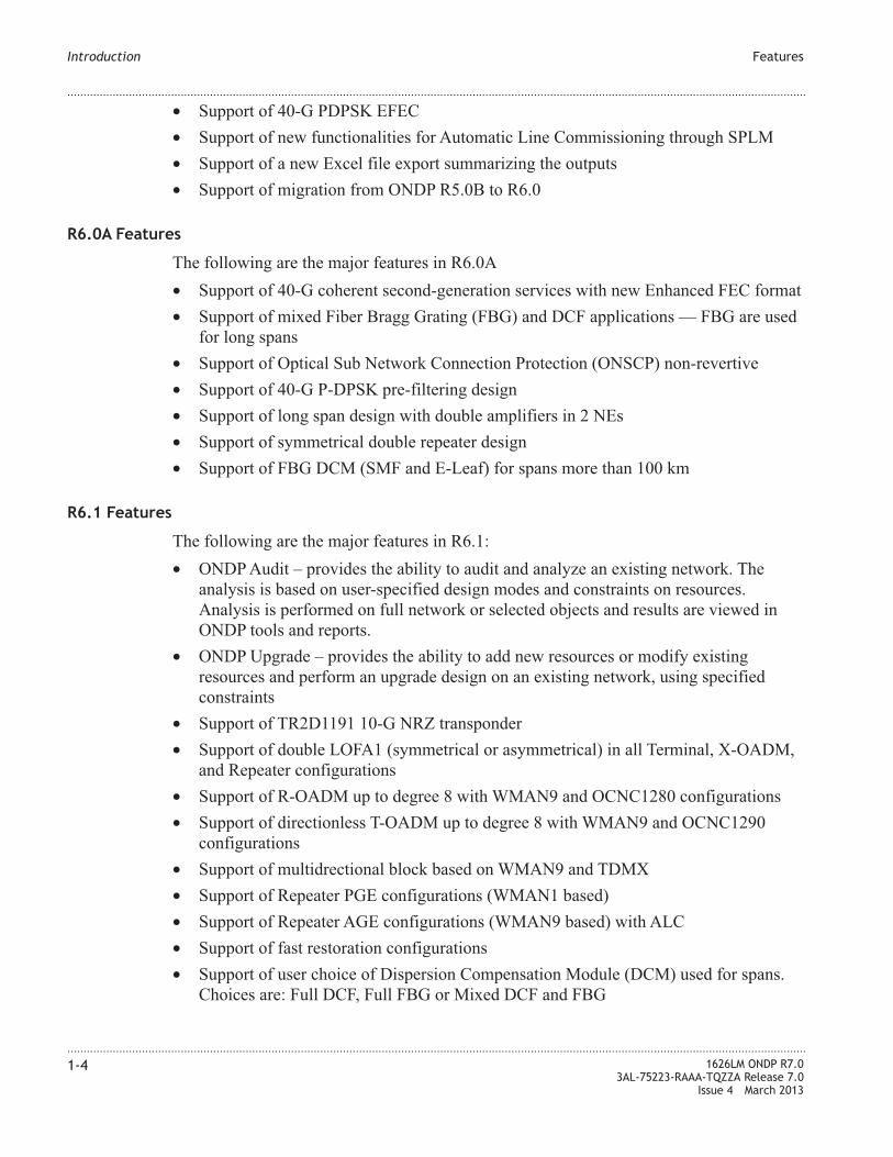
• Support of 40-G PDPSK EFEC
• Support of new functionalities for Automatic Line Commissioning through SPLM
• Support of a new Excel file export summarizing the outputs
• Support of migration from ONDP R5.0B to R6.0
R6.0A Features
The following are the major features in R6.0A
• Support of 40-G coherent second-generation services with new Enhanced FEC format
• Support of mixed Fiber Bragg Grating (FBG) and DCF applications — FBG are used
for long spans
• Support of Optical Sub Network Connection Protection (ONSCP) non-revertive
• Support of 40-G P-DPSK pre-filtering design
• Support of long span design with double amplifiers in 2 NEs
• Support of symmetrical double repeater design
• Support of FBG DCM (SMF and E-Leaf) for spans more than 100 km
R6.1 Features
The following are the major features in R6.1:
• ONDP Audit – provides the ability to audit and analyze an existing network. The
analysis is based on user-specified design modes and constraints on resources.
Analysis is performed on full network or selected objects and results are viewed in
ONDP tools and reports.
• ONDP Upgrade – provides the ability to add new resources or modify existing
resources and perform an upgrade design on an existing network, using specified
constraints
• Support of TR2D1191 10-G NRZ transponder
• Support of double LOFA1 (symmetrical or asymmetrical) in all Terminal, X-OADM,
and Repeater configurations
• Support of R-OADM up to degree 8 with WMAN9 and OCNC1280 configurations
• Support of directionless T-OADM up to degree 8 with WMAN9 and OCNC1290
configurations
• Support of multidrectional block based on WMAN9 and TDMX
• Support of Repeater PGE configurations (WMAN1 based)
• Support of Repeater AGE configurations (WMAN9 based) with ALC
• Support of fast restoration configurations
• Support of user choice of Dispersion Compensation Module (DCM) used for spans.
Choices are: Full DCF, Full FBG or Mixed DCF and FBG
Introduction Features
....................................................................................................................................................................................................................................
....................................................................................................................................................................................................................................
1-4 1626LM ONDP R7.0
3AL-75223-RAAA-TQZZA Release 7.0
Issue 4 March 2013

R7.0 Features
The following are the major features in R7.0:
• Support of the following 100 G transponder and concentrator boards:
– 112SCA1 - 100Gb/s coherent transponder, NRZ PDM-QPSK modulation format
with EFEC, with CFP module at client side, and embedded ROFA on Tx side;
50GHz grid
– 112SCX10 - coherent 10x10Gb/s concentrator in 100Gb/s, NRZ PDM-QPSK with
EFEC, with XFP at client side and embedded ROFA on Tx side; 50GHz grid.
– 112SX10U - coherent 10x10Gb/s concentrator in 100Gb/s, NRZ PDM-QPSK
with EFEC, with XFP at client side, 1 UDC at 10Mbits and embedded ROFA on
Tx side; 50GHz grid
• Support of the following 40 G transponder and concentrator boards:
– TRBC4616 P-DPSK with new Enhanced FEC (only one TDCM) )
– TRBC4716 NRZ PDM-BPSK with new Enhanced FEC format with XFP on client
side, optional Tx PCDC; 50GHz grid
• Support of 1830PSS PSS32 shelf for 100G transponders
– Support of RSA-ETSI ONERACK with MANGTRU
– Support of 1830PSS Equipment Controller used as Second Level Controller in
1626LM
– Support of FAN32H - high power dissipation unit
• Support of cascade of concentrators, (2.5G->10G->40G): TRBC1191 (client side)
connected to TRBC4_16, (WDM line side). OSNCP protection is supported in this
configuration
• Support of TRBC1191 - 50 GHz: 4 x 2.5G concentrator, NRZ, pluggabe client, no
PCDC
• Support of the following below 2.5G clients mapped into 2.5G or 10G:
– STM16, CBR 2.5G on TRBC1x9z
• Support of the following 40G clients mapped into 40G
– OTU3 on TRBD4xy6 (NNI at 43.0 GBps)
• Support of the following 10G clients mapped into 40G:
– STM64, OC192, 10GbEWAN, and CBR10G on TRBC4xyz boards
– Mix of any 10G format supported on TRBC4x16 boards
– 10GbELAN supported on TRBC4xyz boards (GFP-F mapping)
– OTU2 supported on TRBC4xy6 boards (NNI at 10.7 Gbps)
• Support of the following 10G clients mapped into 100G:
– STM64, OC192, 10GbELAN, CBR10G on 100 G concentrator
– 10 GbELAN on 100G concentrator (bit transparent mapping) Use GMP
Introduction Features
....................................................................................................................................................................................................................................
....................................................................................................................................................................................................................................
1626LM ONDP R7.0
3AL-75223-RAAA-TQZZA Release 7.0
Issue 4 March 2013
1-5

– OTU2 on 100G concentrator (NNI at 10.7 Gbps) Use GMP
– OTU2e on 100G concentrator (NNI at 11.1 Gbps) Use GMP
• Support of the following 100G clients mapped into 100G:
– 100GbELAN via GMP on 112SCA1
• OTU4 signal regeneration with 112SCX10 for transmission by 112SCA1 or
112SCX10
OTU4 signal regeneration with 112SC10U for transmission by 112SC10U
• Automatic design with ONDP and GMPLS impacts:
– Mix of two modulation formats: 10G (TRB1191 non-coherent/100Gb coherent
– Mix of two modulation formats: 40G non-coherent (TRB4616) and 100G
coherent
– Mix of two modulation formats: 40G coherent (TRB4617) and 100 G coherent
– Mix of two modulation formats: 100G coherent (112SX10U) and 100G coherent
(112SCA1 or 112SCX10)
– DCM free with LOFA1 and coherent transponders
– 100G coherent in DCU managed network (112SX10U)
– GMPLS - Most disjoint service: ONDP alignment with respect to 1626LM R7.0
GMRE
– GMPLS - Wavelength reuse: ONDP alignment with respect to 1626LM R7.0
GMRE
• Management of ASE (Amplify Spontaneous Emission) noise inducing A/D penalties
with respect to node Optical architecture: Step1:
– For nominal routes, complete OSNR calculation including A/D penalties
– For restoration routes, application of constant penalties
• OSNCP protection based on OCPU board place in1626LM generic shelf and 100 G
coherent board hosted in PSS32 shelf: 112SX10U and 112SCA1
• Alarm for amplifier gain out of range – Amplifier gain minimum and maximum
parameters are provided to detect the variation of the amplifier gain outside of a
planned range.
• End to end service grooming – grooming of services can be done from source to
destination based on the concentrators managed: TRBC4616, TRBC4716, and ETHC.
• Favor or forbid manual definition of regeneration site – during automatic design, the
user can favor a site to receive regeneration, if needed, or forbid a site to receive
regeneration. It is also possible to add a regeneration site.
• Management of number of OMS channels – the user is able to improve performance
by setting different maximum number of OMS channels for subsets
• User name assignment for OMS, OTS, and local OTS.
• Network design including G653 Dispersion Shifted Fibers (DSF)
• ILA site names management – also applies to bypass sites
Introduction Features
....................................................................................................................................................................................................................................
....................................................................................................................................................................................................................................
1-6 1626LM ONDP R7.0
3AL-75223-RAAA-TQZZA Release 7.0
Issue 4 March 2013

• Multidirectional Add/Drop block differentiation for services
• Manual modification of shelves by the user after running the design is supported. This
is applicable on all sites except ILA and bypass sites. These modifications are
accepted by ONDP without checks.
• Incremental design step view based on services.
• Encryption of the .ONDP file
• ONDP read-only version
• Network Description Table (NDT) generation for the entire network
• Statistic tool providing the number of NEs and the number of OMSs in a network
Introduction Features
....................................................................................................................................................................................................................................
....................................................................................................................................................................................................................................
1626LM ONDP R7.0
3AL-75223-RAAA-TQZZA Release 7.0
Issue 4 March 2013
1-7

Functionality
Network size
The following describes the network design capacity of ONDP.
• 500 NEs
• 1000 Links
• 100 Relations
Design options
ONDP supports the greenfield and brownfield design of based networks. The user can
create and configure a network in a variety of ways.
• Begin the network design from scratch
• Copy and paste external network design information from an Excel spreadsheet
• Load a saved ONDP design file from another user
Both external and initial configurations contain the following network design element
data, which can be edited:
• Site (which contains only one NE in this release)
• Link
• Spans
• Traffic matrix
In engineering and planning the network design, the following options can be configured:
• WDM layer
• Packet layer
• Optimization setting
• Results
Results options
The design results are displayed either graphically, in table format or in a log format.
Introduction Functionality
....................................................................................................................................................................................................................................
....................................................................................................................................................................................................................................
1-8 1626LM ONDP R7.0
3AL-75223-RAAA-TQZZA Release 7.0
Issue 4 March 2013

The ONDP Interface
The ONDP GUI
The ONDP GUI provides a user-friendly interface to enter data and gives easy access to
the full functionality of the tool. The following is an illustration of the ONDP GUI. The
associated windows and tasks are described later in this document.
Figure 1-1 The ONDP GUI
Introduction The ONDP Interface
....................................................................................................................................................................................................................................
....................................................................................................................................................................................................................................
1626LM ONDP R7.0
3AL-75223-RAAA-TQZZA Release 7.0
Issue 4 March 2013
1-9

Introduction The ONDP Interface
....................................................................................................................................................................................................................................
....................................................................................................................................................................................................................................
1-10 1626LM ONDP R7.0
3AL-75223-RAAA-TQZZA Release 7.0
Issue 4 March 2013

2 2Installation and Startup
Overview
Purpose
This chapter provides information on how to install, uninstall, launch, and exit the ONDP
application.
Contents
Installation Requirements 2-2
Installer Welcome Window 2-4
InstallShield Wizard Window 2-6
Install ONDP 2-7
Update ONDP Version 2-10
Uninstall ONDP 2-12
Launch ONDP 2-13
Close ONDP 2-14
...................................................................................................................................................................................................................................
1626LM ONDP R7.0
3AL-75223-RAAA-TQZZA Release 7.0
Issue 4 March 2013
2-1

Installation Requirements
Hardware and software requirements
ONDP is distributed via download. Your Alcatel-Lucent ONDP representative will supply
you with details on how to obtain the software. All required software is included in the
installation. The following hardware and software are required on the PC before you
begin installing the ONDP application.
Table 2-1 Minimum PC Requirements
Processor Pentium IV 2.8 GHz
RAM 1 Gb
Operating System Windows XP
Java Version Version 6 Build 1.6
Check/Update Java Version
To check the Java version installed on your PC follow this path: Start > Settings >
Control Panel > Java > General > About...
To update the Java version installed on your PC, follow this path: Start > Settings >
Control Panel > Java > Update > Update Now
License key
The following are the types of license keys supported by ONDP.
• Client - provides access privileges for most of the system. Expert fields are excluded
from view.
• Bidder - provides access privileges for most of the system.
• Expert - provides access privileges to the entire system
• Read-only - provides viewing privileges, but design and topology changes are not
allowed
To start ONDP successfully, you must install the license key. Use the following process to
obtain a license key and install the license key on your PC.
• Install ONDP on the PC. For more information see the “Install ONDP” (p. 2-7) task.
• Once installed, launch the ONDP application. For more information, see the “Launch
ONDP” (p. 2-13) task.
• The ONDP application supplies a code, which you send to your Alcatel-Lucent ONDP
representative.
• The Alcatel-Lucent ONDP representative returns a License.ondp file, which you copy
into the ONDP folder using this path:
Installation and Startup Installation Requirements
....................................................................................................................................................................................................................................
....................................................................................................................................................................................................................................
2-2 1626LM ONDP R7.0
3AL-75223-RAAA-TQZZA Release 7.0
Issue 4 March 2013

C:/Program Files/<ONDP Installation Directory>/ONDP X.X (where X.X is the
release number).
Using this process, the ONDP application will launch successfully.
Troubleshooting the installation
In order for the ONDP installation to be successful, the folder ONDP_shared_compo-
nents must be installed in the C:/Program Files folder. Users who install the ONDP
application in a folder other than C:/Program Files must create a folder named
C:/Program Files and copy the ONDP_shared_components folder into it. Using a folder
other than C:/Program Files usually applies to users whose PC language is other than
English.
Example:
On a PC for which the language is Italian, the ONDP application is installed in the
C:/Programmi folder. This user must create a folder located under C:/ called Program
Files. The user must then copy the ONDP_shared_components folder from the
C:/Programmi folder into the C:/Program Files folder.
Installation and Startup Installation Requirements
....................................................................................................................................................................................................................................
....................................................................................................................................................................................................................................
1626LM ONDP R7.0
3AL-75223-RAAA-TQZZA Release 7.0
Issue 4 March 2013
2-3
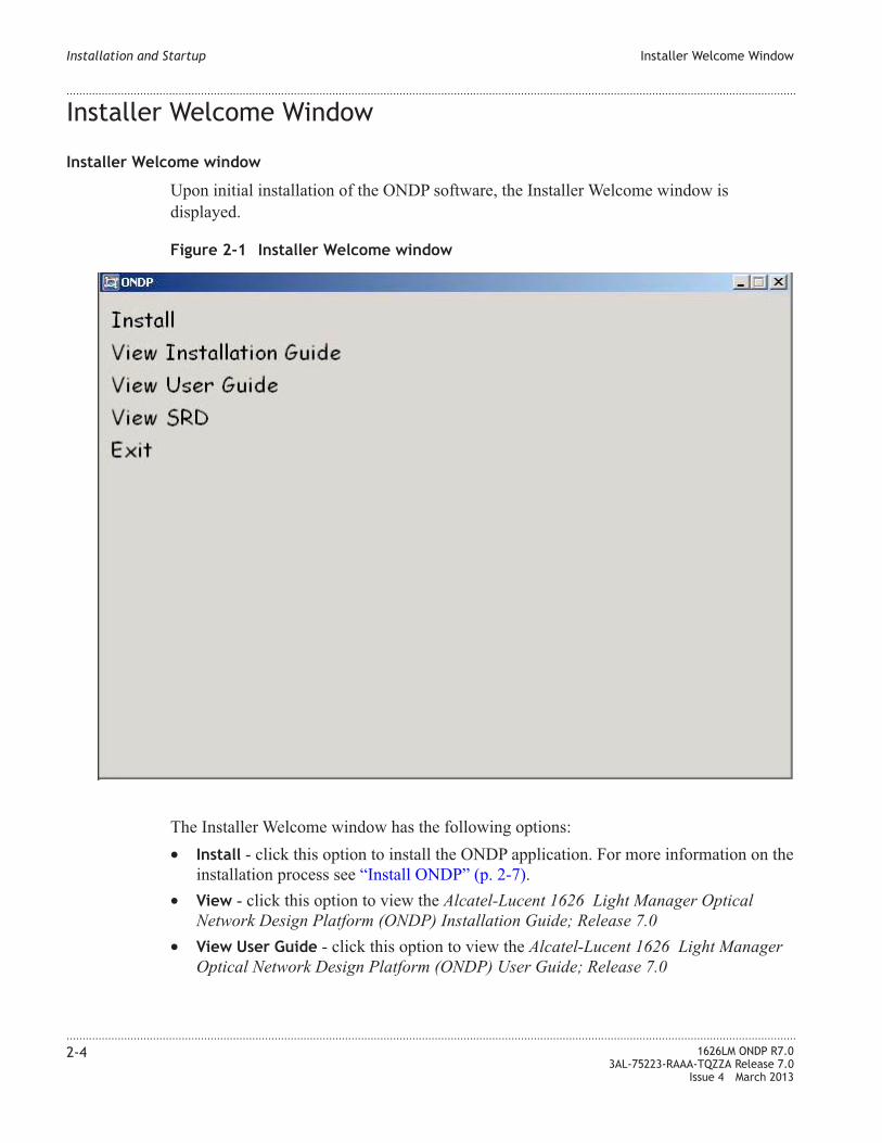
Installer Welcome Window
Installer Welcome window
Upon initial installation of the ONDP software, the Installer Welcome window is
displayed.
The Installer Welcome window has the following options:
• Install - click this option to install the ONDP application. For more information on the
installation process see “Install ONDP” (p. 2-7).
• View - click this option to view the Alcatel-Lucent 1626 Light Manager Optical
Network Design Platform (ONDP) Installation Guide; Release 7.0
• View User Guide - click this option to view the Alcatel-Lucent 1626 Light Manager
Optical Network Design Platform (ONDP) User Guide; Release 7.0
Figure 2-1 Installer Welcome window
Installation and Startup Installer Welcome Window
....................................................................................................................................................................................................................................
....................................................................................................................................................................................................................................
2-4 1626LM ONDP R7.0
3AL-75223-RAAA-TQZZA Release 7.0
Issue 4 March 2013

• View SRD - click this option to view the Software Release Description (SRD), which
is a summary of the software release features.
• Exit - click this option to exit the installation.
Installation and Startup Installer Welcome Window
....................................................................................................................................................................................................................................
....................................................................................................................................................................................................................................
1626LM ONDP R7.0
3AL-75223-RAAA-TQZZA Release 7.0
Issue 4 March 2013
2-5
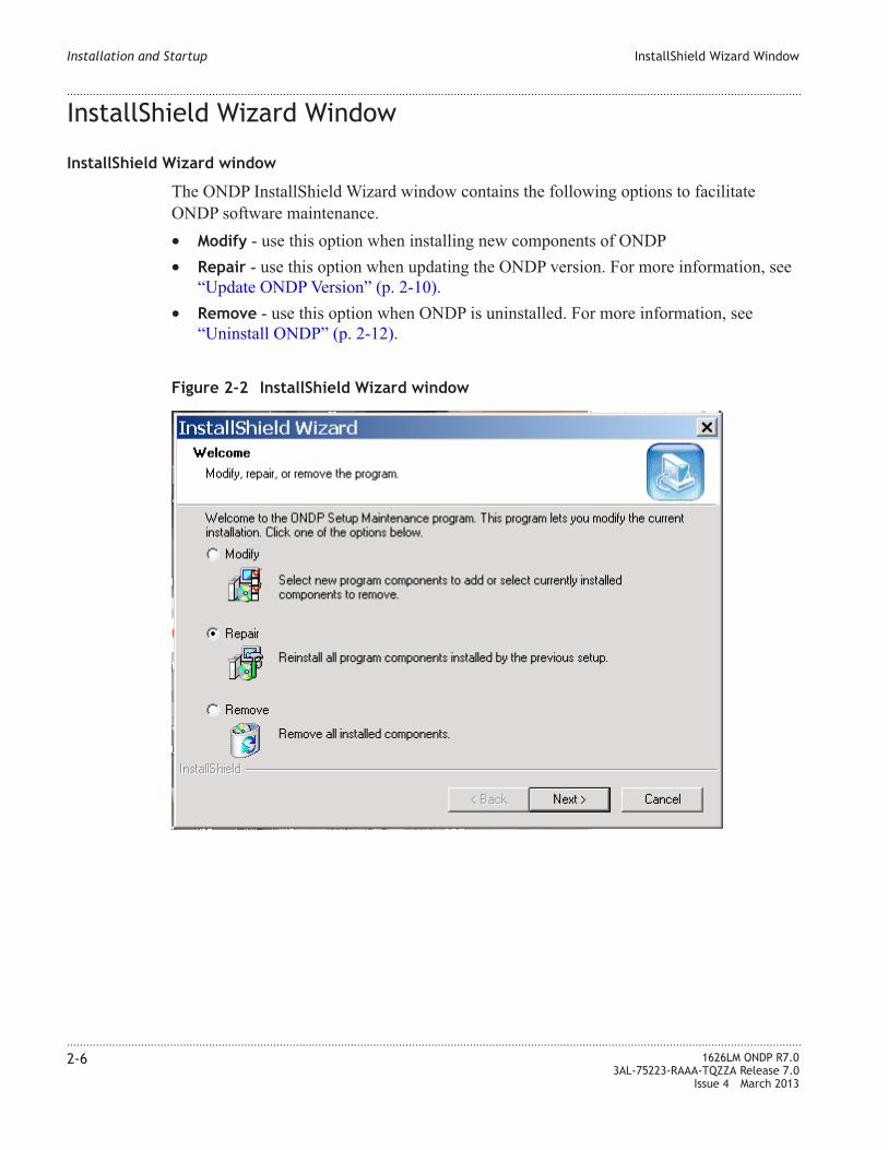
InstallShield Wizard Window
InstallShield Wizard window
The ONDP InstallShield Wizard window contains the following options to facilitate
ONDP software maintenance.
• Modify - use this option when installing new components of ONDP
• Repair - use this option when updating the ONDP version. For more information, see
“Update ONDP Version” (p. 2-10).
• Remove - use this option when ONDP is uninstalled. For more information, see
“Uninstall ONDP” (p. 2-12).
Figure 2-2 InstallShield Wizard window
Installation and Startup InstallShield Wizard Window
....................................................................................................................................................................................................................................
....................................................................................................................................................................................................................................
2-6 1626LM ONDP R7.0
3AL-75223-RAAA-TQZZA Release 7.0
Issue 4 March 2013

Install ONDP
When to use
Use this task to install ONDP on the PC.
Related information
See the following topic in this document:
• “Installation Requirements” (p. 2-2)
Before you begin
This task does not have any preconditions.
Task
Complete the following steps to install ONDP.
...................................................................................................................................................................................................
1 Download the iso file. This iso file will be the virtual CD-ROM.
ONDP is distributed via a downloaded iso file. Your Alcatel-Lucent ONDP representative
will supply you with details on how to obtain this file.
...................................................................................................................................................................................................
2 Do one of the following to start the installer:
• If your PC is configured to run automatically from the CD-ROM drive, the
InstallShield wizard automatically starts.
Result: The Installer Welcome window is displayed. Move to Step 3.
• If your PC is not configured to run automatically, do one of the following:
From the Windows Start
menu, select Start > Run
To display the Installer
Welcome window, browse to
locate and run the setup file:
<CD-ROM
drive>/ONDPInstall.exe
The Installer Welcome
window is displayed. Move
to Step 3.
To skip the Installer
Welcome window, browse to
locate and run the setup file:
<CD-ROM drive>/Setup.exe
The License Agreement
Terms window is displayed.
Move to Step 4.
Installation and Startup Install ONDP
....................................................................................................................................................................................................................................
....................................................................................................................................................................................................................................
1626LM ONDP R7.0
3AL-75223-RAAA-TQZZA Release 7.0
Issue 4 March 2013
2-7

From the <ONDP
Installation Directory>/
To display the Installer
Welcome window,
double-click
ONDPInstall.exe
The Installer Welcome
window is displayed. Move
to Step 3.
To skip the Installer
Welcome window,
double-click Setup.exe
The License Agreement
Terms window is displayed.
Move to Step 4.
Note: The Installer Welcome window contains options to view the User Guide or
SRD. For information on the Installer Welcome window, see “Installer Welcome
Window” (p. 2-4).
...................................................................................................................................................................................................
3 From the Installer Welcome window, click the Install option to initiate the installation
process.
Result: The License Agreement Terms window is displayed.
...................................................................................................................................................................................................
4 Click the Yes button to accept the terms of the license agreement.
Result: The installation notes are displayed
...................................................................................................................................................................................................
5 Read the installation notes and then click the Next button.
Result: The Installation Directory window is displayed.
...................................................................................................................................................................................................
6 To specify an installation directory, do one of the following:
• To accept the default directory, click the Next button.
• To use a different directory, enter the directory name or browse to select a directory,
and then click the Next button.
Result: The Start menu configuration window is displayed.
...................................................................................................................................................................................................
7 To specify a program folder in the Start menu, do one of the following:
• To accept the default folder, click the Next button.
• To use a different directory, enter the directory name or browse to select a directory,
and then click the Next button.
Result: The Installation Summary window displays the products to be installed.
...................................................................................................................................................................................................
8 Click the Next button.
Installation and Startup Install ONDP
....................................................................................................................................................................................................................................
....................................................................................................................................................................................................................................
2-8 1626LM ONDP R7.0
3AL-75223-RAAA-TQZZA Release 7.0
Issue 4 March 2013

Result: The Installation Summary window displays the installation progress.
...................................................................................................................................................................................................
9 When the installation is complete, click the Finish button.
Result: ONDP is installed.
Installation and Startup Install ONDP
....................................................................................................................................................................................................................................
....................................................................................................................................................................................................................................
1626LM ONDP R7.0
3AL-75223-RAAA-TQZZA Release 7.0
Issue 4 March 2013
2-9
E N D O F S T E P S...................................................................................................................................................................................................

Update ONDP Version
When to use
Use this task to update the version of ONDP from the version currently installed on the
PC.
When you load the update version on your PC, an executable file is loaded in this format:
ONDP_X_X_build_nn_installer_dd_mm_yyyy.exe. X_X is the release number, and nn is
the version number within the release.
Before you begin
Before you begin this task, ONDP must be installed on the PC, and you must obtain the
upgrade software and load it on the PC. Upgrades are provided by your Alcatel-Lucent
representative. You will receive instructions on how to load the upgrade.
Note: To verify that the version is updated after completion of this task, view and
compare the current version of ONDP in the Help option on the Main menu.
Task
Complete the following steps to update the ONDP version.
...................................................................................................................................................................................................
1 Follow the instructions provided by your Alcatel-Lucent local customer service support
team, to load the ONDP update on your PC.
Result: The update software is loaded.
...................................................................................................................................................................................................
2 Browse to the ONDP update executable file ONDP_X_X_build_nn_installer_dd_m-
m_yyyy.exe and run the file.
Result: The ONDP InstallShield Wizard screen is displayed, indicating the installation
progress.
...................................................................................................................................................................................................
3 At the ONDP “InstallShield Wizard Window” (p. 2-6), select Repair and click the Next
button.
Inportant: Always use the Repair option to ensure that the ONDP version is updated
correctly.
Result: The InstallShield Wizard Set up Status is displayed and when the version
update is complete the message Maintenance Complete is displayed.
...................................................................................................................................................................................................
4 Click Finish.
Installation and Startup Update ONDP Version
....................................................................................................................................................................................................................................
....................................................................................................................................................................................................................................
2-10 1626LM ONDP R7.0
3AL-75223-RAAA-TQZZA Release 7.0
Issue 4 March 2013

Result: The ONDP version update is complete.
Installation and Startup Update ONDP Version
....................................................................................................................................................................................................................................
....................................................................................................................................................................................................................................
1626LM ONDP R7.0
3AL-75223-RAAA-TQZZA Release 7.0
Issue 4 March 2013
2-11
E N D O F S T E P S...................................................................................................................................................................................................

Uninstall ONDP
When to use
Use this task to uninstall ONDP from the PC.
Before you begin
This task does not have any preconditions.
Task
Complete the following steps to uninstall ONDP.
...................................................................................................................................................................................................
1 From the PC Start menu, select Programs > Alcatel-Lucent > ONDP X.X > Uninstall
ONDP X.X. (where X.X is the release number)
Result: The InstallShield Wizard window is displayed.
...................................................................................................................................................................................................
2 From the InstallShield Wizard window, select the Remove option button and then click
the Next button.
Result: The Confirm File Deletion box is displayed.
...................................................................................................................................................................................................
3 Click OK.
Result: The uninstall process is started, and a confirmation box is displayed.
...................................................................................................................................................................................................
4 Click Finish.
Result: ONDP is uninstalled.
Installation and Startup Uninstall ONDP
....................................................................................................................................................................................................................................
....................................................................................................................................................................................................................................
2-12 1626LM ONDP R7.0
3AL-75223-RAAA-TQZZA Release 7.0
Issue 4 March 2013
E N D O F S T E P S...................................................................................................................................................................................................

Launch ONDP
When to use
Use this task to launch the ONDP application on the PC.
Before you begin
Before you begin this procedure, ensure that the ONDP application is installed on the PC,
and the ONDP icon appears on the desktop.
Task
Complete the following steps to launch the ONDP application on the PC.
...................................................................................................................................................................................................
1 Do one of the following:
• Double click the ONDP X.X icon on the PC desktop. (where X.X is the release
number)
• From the PC Start menu, select Programs > Alcatel-Lucent > ONDP X.X >
ONDP.exe. (where X.X is the release number)
Note: Alcatel-Lucent is the default installation folder. If you have created another
folder under which ONDP is installed, use that path to locate the ondp.exe file.
Result: The ONDP main window is displayed.
Installation and Startup Launch ONDP
....................................................................................................................................................................................................................................
....................................................................................................................................................................................................................................
1626LM ONDP R7.0
3AL-75223-RAAA-TQZZA Release 7.0
Issue 4 March 2013
2-13
E N D O F S T E P S...................................................................................................................................................................................................

Close ONDP
When to use
Use this task to close the ONDP application on the PC.
Before you begin
Before you begin this procedure, ensure that the ONDP application is installed on the PC,
and configuration changes are saved prior to closing the application.
Task
Complete the following steps to close the ONDP application on the PC.
...................................................................................................................................................................................................
1 Do one of the following:
If... Then...
You want to save all configuration changes to
the existing file
Select File > Save. Changes are saved to the
current project
Select File > Exit
You want to save all configuration changes to
a new file
Select File > Save As
A window is displayed where you can name
the file and place it in the desired directory.
You do not want to save any configuration
changes
Select File > Exit
A Warning box is displayed, which warns that
modifications are detected and will be lost.
Click Continue
Result: The ONDP application is closed.
Installation and Startup Close ONDP
....................................................................................................................................................................................................................................
....................................................................................................................................................................................................................................
2-14 1626LM ONDP R7.0
3AL-75223-RAAA-TQZZA Release 7.0
Issue 4 March 2013
E N D O F S T E P S...................................................................................................................................................................................................

3 3ONDP User Interface
Overview
Purpose
This chapter provides information about the ONDP user interface.
Contents
Main Menu and Toolbar 3-2
Map Legend 3-13
...................................................................................................................................................................................................................................
1626LM ONDP R7.0
3AL-75223-RAAA-TQZZA Release 7.0
Issue 4 March 2013
3-1

Main Menu and Toolbar
Overview
Network design can be accomplished by using the ONDP menus, toolbar, and associated
windows. The following sections describe the Main menu and toolbar.
The Main menu
The Main menu contains the following options:
• File
• Edit
• Display
• Inputs
• Design
• Reports
• Tools
• Misc.
• Help
File menu
Table 3-1 File menu descriptions
File menu command Description
New Project Create a new design project
Open Project Open an existing design project
Save Save the current design to a default file name
Figure 3-1 File menu
ONDP User Interface Main Menu and Toolbar
....................................................................................................................................................................................................................................
....................................................................................................................................................................................................................................
3-2 1626LM ONDP R7.0
3AL-75223-RAAA-TQZZA Release 7.0
Issue 4 March 2013

Table 3-1 File menu descriptions (continued)
File menu command Description
Save As Save the current design to a designated file name and
location
Encrypt ONDP file on saving Click the checkbox to encrypt the .ondp file while saving.
To deactivate the encryption, uncheck the checkbox while
saving the .ondp file. For more information, see “ONDP
project file encryption” (p. 4-5)
Exit Close ONDP and exit the application
Edit menu
Table 3-2 Edit menu descriptions
Edit menu command Description
Undo Undo the last action performed
Redo Redo the last action that was undone
Delete Selected Remove the selected items
Select All Select all items in the Topology Map
Clear All Clear all previously selected items
Invert Selection Reverse the status of selection of all the items on the map.
Those items in the selected state are cleared and items in
the cleared state are selected.
Figure 3-2 Edit menu
ONDP User Interface Main Menu and Toolbar
....................................................................................................................................................................................................................................
....................................................................................................................................................................................................................................
1626LM ONDP R7.0
3AL-75223-RAAA-TQZZA Release 7.0
Issue 4 March 2013
3-3

Table 3-2 Edit menu descriptions (continued)
Edit menu command Description
Highlight All Selected Highlight the selected items on the Map.
Insert Step After Current One Stop the current design step and begin the next step in the
incremental design. For more information on Incremental
Design, see “Incremental Design” (p. 4-6).
Delete Current Step Delete all resources added during the current step in the
incremental design. For more information on Incremental
Design, see “Incremental Design” (p. 4-6).
Highlight Current Step Highlight all resources added during the current step in the
incremental design on the Topology map. For more
information on Incremental Design, see “Incremental
Design” (p. 4-6).
Display menu
Table 3-3 Display menu descriptions
Display menu command Description
Display NE Sites Display/hide NE sites on the Topology map
Display xGE Sites Display/hide xGE sites on the Topology map
Display Labels Display/hide labels on the Topology map
Display Links Display/hide links on the Topology map
Figure 3-3 Display menu
ONDP User Interface Main Menu and Toolbar
....................................................................................................................................................................................................................................
....................................................................................................................................................................................................................................
3-4 1626LM ONDP R7.0
3AL-75223-RAAA-TQZZA Release 7.0
Issue 4 March 2013

Table 3-3 Display menu descriptions (continued)
Display menu command Description
Display Relations Display/hide relations on the Topology map
Display Map Display/hide the background map.
Display Edge Tooltips Display/hide the Edge Tooltip for links and relations on the
Topology Map. For more information, see “Edge Tooltip”
(p. 3-14)
Use Large Icons Display elements on the Topology map using largest size
icons
Use Medium Icons Display elements on the Topology map using the medium
size icons
Use Small Icons Display elements on the Topology map using the smallest
size icons
Inputs menu
Table 3-4 Inputs menu descriptions
Inputs menu command Description
Edit Sites Open the Edit Sites window to edit Site properties. For
more information, see “Section 2: Sites” (p. 4-13)
Edit ILAs Open the Edit ILAs window to edit ILA properties. For
more information, see “Section 3: ILAs” (p. 4-30).
Figure 3-4 Inputs menu
ONDP User Interface Main Menu and Toolbar
....................................................................................................................................................................................................................................
....................................................................................................................................................................................................................................
1626LM ONDP R7.0
3AL-75223-RAAA-TQZZA Release 7.0
Issue 4 March 2013
3-5

Table 3-4 Inputs menu descriptions (continued)
Inputs menu command Description
Edit Links/Spans Open the Edit Spans window to edit Links and Spans to set
physical link properties. For more information, see “Section
4: Links and Spans” (p. 4-36)
Edit Relations/Services Open the Edit Services window to edit Relations and
Services logical link properties. For more information, see
“Section 5: Relations and Services” (p. 4-56)
Edit Optical Subsets Open the Optical Subsets window to create and edit Optical
Subset properties. For more information, see “Section 6:
Optical Subsets” (p. 4-88)
Edit SRGs Open the Edit SRGs window to edit Shared Risk Groups.
For more information, see “Shared Risk Groups (SRGs)”
(p. 4-99)
Automatic Failure Scope A check in the check box indicates all failure analysis is
done by ONDP based on link and SRG failures only.
Multidirect Add/Drop blocks and Sites are excluded. When
the checkbox is cleared, the Edit Failure Scope command
becomes available for selection, and the failure scope can
be manually defined.
Edit Failure Scope Open the Failures Scope window. This command is
available for selection when the Automatic Failure Scope
command is unchecked. For more information, see
“Failures Scope” (p. 4-105)
Set Design Parameters Open the Design Parameters window to set the network
design configuration parameters. For more information, see
“Section 8: Design Parameters” (p. 4-114)
ONDP User Interface Main Menu and Toolbar
....................................................................................................................................................................................................................................
....................................................................................................................................................................................................................................
3-6 1626LM ONDP R7.0
3AL-75223-RAAA-TQZZA Release 7.0
Issue 4 March 2013

Design menu
Table 3-5 Design menu descriptions
Design menu command Description
Run Full Design [Links + Traffic] Run the full design and produce a network according to the
specified design elements and network design configuration
parameters. This command is the shortcut to run the links
design followed by a traffic design. For more information,
see “The Network Design” (p. 5-2).
Run Full Links Design only Run a partial design to optimize optical parameters such as
amplifier position, dispersion mapping optimization, and
amplifier type settings optimization. For more information,
see “The Network Design” (p. 5-2).
Run Full Traffic Design only Run a partial design to resolve the traffic matrix. Performs a
wavelength allocation, a dimensioning, and a shelf
computation. This operation is only possible if a links
design has been previously triggered. For more
information, see “The Network Design” (p. 5-2).
Figure 3-5 Design menu
ONDP User Interface Main Menu and Toolbar
....................................................................................................................................................................................................................................
....................................................................................................................................................................................................................................
1626LM ONDP R7.0
3AL-75223-RAAA-TQZZA Release 7.0
Issue 4 March 2013
3-7

Reports menu
Table 3-6 Reports menu descriptions
Reports menu command Description
Show/Tune Selected Links Design Open the Edit route optical design window for selected
links which displays the results of the design. For more
information, see “Show/Tune Selected Links Design ”
(p. 6-3)
Show Selected Links Physical
Diagnostics
Open the Optical design window for the selected links,
which displays the optical design analysis in graphical
format. For more information, see “Show Selected Links
Physical Diagnostics” (p. 6-6)
Show Selected Links Real-Time
Fast Feasibility Criteria
Open a graphical representation of the optical feasibility
of selected links between nodes. For more information,
see “Show Selected Links Real-Time Fast Feasibility
Criteria” (p. 6-15)
Show Graphical Statistics Open the Statistics window which enables the ability to
show design results for Sites and Links graphically on the
Topology map. For more information, see “Show
Graphical Statistics” (p. 6-17)
Figure 3-6 Reports menu
ONDP User Interface Main Menu and Toolbar
....................................................................................................................................................................................................................................
....................................................................................................................................................................................................................................
3-8 1626LM ONDP R7.0
3AL-75223-RAAA-TQZZA Release 7.0
Issue 4 March 2013

Table 3-6 Reports menu descriptions (continued)
Reports menu command Description
Show Network Statistics Open the Network Statistics window which displays high
level statistical values of the network design optimization.
For more information, see “Show Network Statistics”
(p. 6-21).
Show Failures Report Open the Failures Report window which shows what
happens to services when a failure on a node/link occurs,
reported as Dead, Restored or not affected. For more
information, see “Show Failures Report” (p. 6-24).
Show GMRE Audit Logs Open the GMRE Audit Logs window which displays the
results of the restoration and protection analysis/failure
analysis. For more information, see “Show GMRE Audit
Logs” (p. 6-31).
Show Traffic Design Logs Open the Traffic design logs window which displays logs
on the network design. For more information, see “Show
Traffic Design Logs” (p. 6-34)
Show Errors Report Open the List Errors window which provides information
about warning messages and errors generated during the
network design. For more information, see “Show Errors
Report” (p. 6-35)
Show Bill of Material Open the Bill of Materials which displays a list of
materials needed to construct the network. For more
information, see “Show Bill of Material” (p. 6-37)
Show Bill of Material (multi-step) Open the Incremental Bill of Material window, which
displays the list of materials needed to construct the
network for each step in the incremental design.
Show Sites/Part List Open the detailed Part List window which displays the
board list with details such as board location and optical
parameters. For more information, see “Show Sites/Part
List” (p. 6-39)
Export Design Results Excel
Report
Open the Excel Export Filtering window to select options
to include in an Excel spreadsheet, and then export the
Excel file of the design results. The report also contains
information about optical design parameters. For more
information, see “Export Design Results Excel Report”
(p. 6-45)
Export BoM Produce output to Comet software for automatic quotation
based on BoM. For more information, see “Export BoM”
(p. 6-71)
ONDP User Interface Main Menu and Toolbar
....................................................................................................................................................................................................................................
....................................................................................................................................................................................................................................
1626LM ONDP R7.0
3AL-75223-RAAA-TQZZA Release 7.0
Issue 4 March 2013
3-9

Tools menu
Table 3-7 Tools menu descriptions
Tools menu command Description
GMRE Simulator Run the GMRE audit, which produces results of restoration
and protection analysis/failure analysis/dimensioning of the
network.
Misc. menu
Table 3-8 Misc menu descriptions
Misc. menu command Description
Product Database Displays commands related to the product database import
and export functions.
Help menu
The Help menu contains the About option, which displays information about the installed
ONDP software.
Figure 3-7 Misc. menu
Figure 3-8 Misc. menu
Figure 3-9 Help menu
ONDP User Interface Main Menu and Toolbar
....................................................................................................................................................................................................................................
....................................................................................................................................................................................................................................
3-10 1626LM ONDP R7.0
3AL-75223-RAAA-TQZZA Release 7.0
Issue 4 March 2013

The Toolbar
The ONDP main window toolbar provides tools to create/edit/interrogate the network.
Table 3-9 Toolbar icon descriptions
Tool tip Icon Description
New Project Create a new design
Open Project Open a saved design
Save Save the current design
Save As Save the current design to a designated file name and
location
Undo Undo the last action performed
Figure 3-10 Help window
ONDP User Interface Main Menu and Toolbar
....................................................................................................................................................................................................................................
....................................................................................................................................................................................................................................
1626LM ONDP R7.0
3AL-75223-RAAA-TQZZA Release 7.0
Issue 4 March 2013
3-11

Table 3-9 Toolbar icon descriptions (continued)
Tool tip Icon Description
Redo Redo the last action that was undone
Delete Selected Remove the selected items
Scale 1:1 Show the network to scale on the Topology Map
Fit to Contents Show the entire network on the Topology Map,
regardless of scale
Select Activate the cursor to select a design element and
deactivate the creation mode
Create Default NE Create an NE at the insertion point with the default
architecture that was specified when creating the
project
Create 3R Create a regeneration site at the insertion point
Create Link Create a link (a sequence of fiber spans) to connect one
site to another. Each link contains at least one fiber
span.
Create Relation Create a relation (which supports a set of service
demands) between two sites. By default, a relation
contains no service.
Run Full Design Run the full analysis on the network design
Show Graphical
Statistics
Open the Graphical Statistics window to display the
results of the network design in graphical format
Optical Margin Tool Display the optical margin available for the set of
selected links
Show Step Slider Display the current step in the Step Slider window.
This window allows the Topology map to display the
resources in the previous or next step in the
Incremental Design. For more information, see
“Incremental Design” (p. 4-6).
ONDP User Interface Main Menu and Toolbar
....................................................................................................................................................................................................................................
....................................................................................................................................................................................................................................
3-12 1626LM ONDP R7.0
3AL-75223-RAAA-TQZZA Release 7.0
Issue 4 March 2013

Map Legend
Overview
The Topology map contains icons that represent and facilitate the network design.
Site icons
The following table describes the types of site icons, which contain Network Elements
(NEs). The site icon displays information about the architecture, connectivity, and name
of the NE. For a detailed description on types of sites and NE architecture, see “Section 2:
Sites” (p. 4-13).
Table 3-10 Site icons
Site icon Description
Undefined NE site. A site which contains only one NE.
This NE is not connected to the network.
Terminal site. A site which contains only one NE. This
NE is a fixed NE and is only connected by one link to the
network. This site is opaque.
OADM site. A site which contains only one NE. This NE
is an R-OADM and can have multiple connections to the
network. This site is transparent.
OADM site. A site which contains only one NE. This NE
is a multidirectional NE. The maximum degree of the NE
is 5.
ONDP User Interface Map Legend
....................................................................................................................................................................................................................................
....................................................................................................................................................................................................................................
1626LM ONDP R7.0
3AL-75223-RAAA-TQZZA Release 7.0
Issue 4 March 2013
3-13

Table 3-10 Site icons (continued)
Site icon Description
3R site. A site which contains only regenerators. This NE
is a fixed NE and is connected by two links to the
network. This site is opaque.
ILA AGE site. A site which contains only one NE. This
NE is connected by two links and is used to correct the
wavelengths tilt. This site is transparent. A user is not
able to create the ILA AGE site. This type of site is
automatically inserted during the links design step.
PGE site when designing APA networks. In this case,
utilize a point to point network with fixed nodes
containing 16 spans.
Edge Tooltip
The Edge tooltip appears by holding the cursor over a link or relation. The information
displayed in the Edge tooltip describes the source and destination of the link/relation. This
information is useful when the entire Topology map is not in view. Additionally, the Edge
tooltip helps distinguish two different fibers with the same source and destination,
indicated as a letter within brackets. This letter is referred to as the Sibling Label. In the
example below, the Sibling Label [A] indicates another fiber exists with the same source
and destination.
Figure 3-11 Edge tooltip
ONDP User Interface Map Legend
....................................................................................................................................................................................................................................
....................................................................................................................................................................................................................................
3-14 1626LM ONDP R7.0
3AL-75223-RAAA-TQZZA Release 7.0
Issue 4 March 2013

Link and Traffic Icons
The following table describes the types of links and traffic icons.
Table 3-11 Traffic Icons
Traffic Icon Description
Link icon. Represents a sequence of fiber spans.
Relations icon. Represents a set of service demands.
Topology Map Pop-up Menu
The Topology Map contains a pop-up menu which has actions that assist in the design. To
access the Topology Map pop-up menu right-click on the Topology Map. Note: ensure
that the cursor is in Select mode, by clicking the Select icon or by clicking the middle
mouse button.
The following table describes the options in the Topology Map pop-up menu.
Table 3-12 Topology Map pop-up menu
Option Description
Create Default NE Create a default NE site at the insertion point
Create Default 3R Create a default regenerator site at the insertion point
Delete All Selected Remove the selected items from the map
Select All Select all design elements on the map
Deselect All Clear all previously selected items.
Figure 3-12 Topology Map Pop menu
ONDP User Interface Map Legend
....................................................................................................................................................................................................................................
....................................................................................................................................................................................................................................
1626LM ONDP R7.0
3AL-75223-RAAA-TQZZA Release 7.0
Issue 4 March 2013
3-15

Table 3-12 Topology Map pop-up menu (continued)
Option Description
Invert Selection Reverse the status of selection of all the items on the map.
Those items in the selected state are cleared and items in
the cleared state are selected.
Highlight All Selected Highlight the selected items on the map
Site Pop-up Menu
Each site on the Topology Map contains a pop-up menu which has actions to edit the site.
To access the Site pop-up menu right-click on the site icon.
The following table describes the options in the Site pop-up menu.
Table 3-13 Site pop-up menu
Option Description
Edit Site Open the Edit NE window to edit the Label, Type, and
Connectivity of the NE. For more information see, “Edit
NE window” (p. 4-18).
Highlight in Table Open the Edit Sites window with the selected site
highlighted in the table. For more information, see “Site
parameters” (p. 4-20).
Highlight on Map Clears all design elements except the selected site on the
Topology Map.
Create Link Create a link to connect one site to another
Create Relation Create an empty relation
Figure 3-13 Site pop-up menu
ONDP User Interface Map Legend
....................................................................................................................................................................................................................................
....................................................................................................................................................................................................................................
3-16 1626LM ONDP R7.0
3AL-75223-RAAA-TQZZA Release 7.0
Issue 4 March 2013

Table 3-13 Site pop-up menu (continued)
Option Description
Delete Deletes the selected site from the Topology Map
Show Part List Opens the Part List window which displays the equipment
parameters. For more information, see “Show Sites/Part
List” (p. 6-39).
Show Equipment View Opens the Edit Equipments window which displays a
graphical representation of equipment and allows NE
creation/editing. For more information, see “Show
Equipment View” (p. 6-40) and “Edit Equipments
window” (p. 8-7).
Link Pop-up Menu
Each link on the Topology Map contains a pop-up menu which has actions to view and
edit the link. To access the Link pop-up menu right-click on the link of interest.
The following table describes the options in the Link pop-up menu.
Table 3-14 Link pop-up menu
Option Description
Highlight in Table For a link of interest, opens the Edit Spans window. The
Link is highlighted in the table. For more information, see
“Edit Spans window” (p. 4-37).
Highlight on Map Clears all design elements except the selected link on the
Topology Map.
Figure 3-14 Link pop-up menu
ONDP User Interface Map Legend
....................................................................................................................................................................................................................................
....................................................................................................................................................................................................................................
1626LM ONDP R7.0
3AL-75223-RAAA-TQZZA Release 7.0
Issue 4 March 2013
3-17

Table 3-14 Link pop-up menu (continued)
Option Description
Delete Deletes the selected Link from the Topology Map
Design Link Run the design process for selected links.
Show/Tune Design Results Opens the Edit route optical design window for selected
links which displays the results of the design. For more
information, see “Show/Tune Selected Links Design ”
(p. 6-3)
Show Physical Diagnostics Opens the Optical design window for the last selected
links, which displays the optical design analysis in
graphical format. For more information, see “Show
Selected Links Physical Diagnostics” (p. 6-6)
Show Real-Time Fast Feasibility
Criteria
Opens a graphical representation of the optical feasibility
of links between nodes. For more information, see “Show
Selected Links Real-Time Fast Feasibility Criteria”
(p. 6-15)
Show Line View [full spectrum] The Line View is used as input for a link. It shows the path
followed by all wavelengths supported by the link. The
full spectrum view provides an ordered view of all
possible wavelengths (used or unused) on the link. For
more information, see “Show Line View” (p. 6-41).
Show Line View [optimized] The Line View is used as input for a link. It shows the path
followed by all wavelengths supported by the link. The
optimized view provides a compact unordered view of the
used wavelengths only. For more information, see “Show
Line View” (p. 6-41).
Relation Pop-up Menu
Each relation on the Topology Map contains a pop-up menu which has actions to view
and edit the relation. To access the Relation pop-up menu right-click on the relation.
ONDP User Interface Map Legend
....................................................................................................................................................................................................................................
....................................................................................................................................................................................................................................
3-18 1626LM ONDP R7.0
3AL-75223-RAAA-TQZZA Release 7.0
Issue 4 March 2013

The following table describes the options in the Relation pop-up menu.
Table 3-15 Relation pop-up menu
Option Description
Highlight in Table For a Relation of interest, opens the Edit Services window.
The selected Relation is highlighted in the table. For more
information, see “Edit Services window” (p. 4-57).
Highlight on Map Clears all design elements except the selected relation on
the Topology Map.
Delete Deletes the selected Relation from the Topology Map
Highlight All Working Path Highlights all working paths on the map.
Highlight All Protecting Path Highlights all protecting paths on the map.
Highlight All Work+Prot Path Highlights all working and protecting paths on the map.
Figure 3-15 Relation pop-up menu
ONDP User Interface Map Legend
....................................................................................................................................................................................................................................
....................................................................................................................................................................................................................................
1626LM ONDP R7.0
3AL-75223-RAAA-TQZZA Release 7.0
Issue 4 March 2013
3-19

ONDP User Interface Map Legend
....................................................................................................................................................................................................................................
....................................................................................................................................................................................................................................
3-20 1626LM ONDP R7.0
3AL-75223-RAAA-TQZZA Release 7.0
Issue 4 March 2013

4 4Design Inputs
Overview
Purpose
This chapter provides information on inputs used to design and plan a network.
Contents
Section 1: Starting the Design 4-3
Design Inputs 4-4
Incremental Design 4-6
Create a New Project 4-9
Open an Existing Project (.ondp file) 4-11
Section 2: Sites 4-13
Sites 4-14
Create Sites 4-24
Edit NE Configuration 4-26
Edit Site Parameters 4-28
Delete Sites 4-29
Section 3: ILAs 4-30
ILAs 4-31
Change ILA Site Name 4-34
Section 4: Links and Spans 4-36
Links and Spans 4-37
Create Links and Spans 4-46
Edit Links and Spans 4-47
Add Spans to Links 4-48
...................................................................................................................................................................................................................................
1626LM ONDP R7.0
3AL-75223-RAAA-TQZZA Release 7.0
Issue 4 March 2013
4-1

Change Span Parameters and Copy to a New Span 4-50
Merge Spans 4-52
Delete Links and Spans 4-54
Identify a Link on the Map 4-55
Section 5: Relations and Services 4-56
Relations and Services 4-57
Create a Relation 4-78
Edit Relations and Services 4-79
Create Services 4-80
Change Service Parameters and Copy to a New Service 4-82
Delete Relations and Services 4-84
Identify a Relation on the Map 4-85
Edit Spatial and Spectral Constraints 4-86
Section 6: Optical Subsets 4-88
Optical Subsets 4-89
Create Optical Subset 4-97
Section 7: Shared Risk Groups (SRGs) and Failure Scope 4-98
Shared Risk Groups (SRGs) 4-99
Failures Scope 4-105
Create an SRG 4-109
Include/Exclude Links/Sites in SRGs 4-110
Delete SRGs 4-111
Edit a Failures Scope 4-112
Section 8: Design Parameters 4-114
Design Parameters 4-115
WDM Layer Design Parameters 4-117
Traffic Setting Design Parameters 4-122
Set Design Parameters 4-125
Design Inputs Overview
....................................................................................................................................................................................................................................
....................................................................................................................................................................................................................................
4-2 1626LM ONDP R7.0
3AL-75223-RAAA-TQZZA Release 7.0
Issue 4 March 2013

Section 1: Starting the Design
Overview
Purpose
This section provides information on how to create, view, and edit design projects.
Contents
Design Inputs 4-4
Incremental Design 4-6
Create a New Project 4-9
Open an Existing Project (.ondp file) 4-11
Design Inputs
Section 1: Starting the Design
Overview
....................................................................................................................................................................................................................................
....................................................................................................................................................................................................................................
1626LM ONDP R7.0
3AL-75223-RAAA-TQZZA Release 7.0
Issue 4 March 2013
4-3

Design Inputs
Design inputs
This chapter describes the design elements required for input in the network design. The
following are the types of inputs that are considered in optical network design planning:
• Sites - for more information, see “Section 2: Sites” (p. 4-13).
• ILAs - for more information, see “Section 3: ILAs” (p. 4-30)
• Links and Spans - for more information, see “Section 4: Links and Spans” (p. 4-36).
• Relations and Services - for more information, see “Section 5: Relations and
Services” (p. 4-56).
• Optical Subsets - for more information, see “Section 6: Optical Subsets” (p. 4-88)
• Shared Risk Groups (SRGs) and Failure Scope - for more information, see “Section 7:
Shared Risk Groups (SRGs) and Failure Scope” (p. 4-98)
• Design Parameters - for more information, see “Section 8: Design Parameters”
(p. 4-114).
Starting the ONDP design
After launching ONDP, the Init [ONDP] window is displayed, from which the user
chooses a default NE architecture and a background map to begin a new network design.
Alternatively, the user selects a saved project to open an existing network design. Each
network design that is created and saved is referred to as a project. The file name format
for saved projects is *.ondp. After a project is created, the project default NE
architecture and the background map cannot be changed.
For more information on NE architecture, see “NE architecture” (p. 4-16).
For more information on background map management, see Chapter 9, “Map
Management”.
Design Inputs
Section 1: Starting the Design
Design Inputs
....................................................................................................................................................................................................................................
....................................................................................................................................................................................................................................
4-4 1626LM ONDP R7.0
3AL-75223-RAAA-TQZZA Release 7.0
Issue 4 March 2013

ONDP project file encryption
Once a project is created, the *.ondp can be saved as an encrypted file. The option to
save projects in the encrypted format is controlled by clicking the Encrypt ONDP file on
saving checkbox in the File menu. Note: All projects saved while the Encrypt ONDP file
on saving checkbox is checked are saved as encrypted files. All project files saved while
the Encrypt ONDP file on saving checkbox is un-checked are saved as un-encrypted files.
This is also true for projects previously saved as encrypted files.
Figure 4-1 Init [ONDP] window
Figure 4-2 Encrypt ONDP file on saving checkbox
Design Inputs
Section 1: Starting the Design
Design Inputs
....................................................................................................................................................................................................................................
....................................................................................................................................................................................................................................
1626LM ONDP R7.0
3AL-75223-RAAA-TQZZA Release 7.0
Issue 4 March 2013
4-5

Incremental Design
Overview
Incremental design is a feature which provides a method of partitioning the network
design into multiple user-defined steps. The user defines the topology and traffic matrix
information for each step. ONDP then performs the multiple step optimization and
provides map views, design results and BOM information on one specific step, a set of
steps or for all steps.
Design steps
The network design is divided into a series of numbered steps. A new design project, or a
network design that is imported is named Step 0 by default. The user determines the point
in the network design when a new step in the incremental design is necessary. Successive
steps in the design are named Step 1, Step 2, and so on.
Add, delete, and display steps
The Edit menu contains options which are related to Incremental Design and allow the
user to add, delete, and display steps in the incremental design.
Table 4-1 Edit menu Incremental Design descriptions
Edit Incremental Design
menu command
Description
Insert Step After Current One End the current design step and begin the next step in the
incremental design.
Delete Current Step Delete all resources added during the current step in the
incremental design.
Highlight Current Step Highlight all resources added during the current step in the
incremental design on the Topology map.
Figure 4-3 Edit menu Incremental Design options
Design Inputs
Section 1: Starting the Design
Incremental Design
....................................................................................................................................................................................................................................
....................................................................................................................................................................................................................................
4-6 1626LM ONDP R7.0
3AL-75223-RAAA-TQZZA Release 7.0
Issue 4 March 2013

Step Slider window
The Step Slider window displays the resources added in specific steps of the Incremental
Design on the Topology map. To see newly added steps in the Step Slider window, close
and re-open the Step slider window as steps are added to the Incremental Design,
To access the Step Slider window, click the Show Step Slider icon in the Main toolbar.
The center box of the Step Slider window indicates the current step number that is
displayed on the Topology map. Selecting the Prev button displays the resources created
in the previous steps of the incremental design on the Topology map. Likewise, selecting
the Next button displays the resources created in the subsequent step. The sliders can also
be used to move between steps, and indicate by their positions where the current step is in
the total design. For example, if a slider is all the way to the right, the indicated step is the
last step of the incremental design.
The following are the types of information the Step Slider can display on the Topology
map.
• Topology - all resources of the specific step are displayed on the Topology map
• Services - displays services added in the specific step on the Topology map. If the
Services slider is on Step 0, all resources for all steps display on the map as the
Topology slider is moved up or down the step counter. When the Services slider is
moved to subsequent steps, only the relations added in the specific step display on the
map. If the Topology and Services sliders are on the same step other than Step 0, only
those relations added in that step are displayed on the map. If the Topology slider is
moved to a higher step, the cumulative relations added in each step display on the
map by moving the Services slider up or down the step counter.
Example: If the Topology slider is on Step 4, and the Services slider is on Step 1, all
relations added in Step 1,Step 2, and Step 3 display on the map. If the Topology slider
is on Step 4 and the Services slider is on Step 3, only those relations added in Step 3
display on the map.
Figure 4-4 Step Slider window
Design Inputs
Section 1: Starting the Design
Incremental Design
....................................................................................................................................................................................................................................
....................................................................................................................................................................................................................................
1626LM ONDP R7.0
3AL-75223-RAAA-TQZZA Release 7.0
Issue 4 March 2013
4-7

Bill of Material (multi-step) report
The Bill of Material (multi-step) report option displays the list of materials needed to
construct the network for each step in the incremental design, for a series of steps in the
incremental design, or for the whole design. For more information on this report, see
“Show Bill of Material (multi-step)” (p. 6-38).
Design Inputs
Section 1: Starting the Design
Incremental Design
....................................................................................................................................................................................................................................
....................................................................................................................................................................................................................................
4-8 1626LM ONDP R7.0
3AL-75223-RAAA-TQZZA Release 7.0
Issue 4 March 2013

Create a New Project
When to use
Use this task to create a network design project. A new project can be created after
launching ONDP, or while working in a current project. New projects are saved with a
.ondp file extension.
Related information
For more information on NE architecture, see “NE architecture” (p. 4-16).
For more information on background maps, see Chapter 9, “Map Management”.
This task has two methods:
• “Task Method 1: Create a New Project From the Launch of ONDP” (p. 4-9)
• “Task Method 2: Create a New Project From the Topology Map” (p. 4-10)
Before you begin
This task does not have any preconditions.
Task Method 1: Create a New Project From the Launch of ONDP
Complete the following steps to create a new design project immediately after launching
the ONDP software.
...................................................................................................................................................................................................
1 Launch the ONDP software
Result: The Init [ONDP] window is displayed.
...................................................................................................................................................................................................
2 Specify a default NE architecture by selecting an option button. Possible selections are:
Fixed, Reconfigurable, Reconfigurable [DPSK], Tunable, Multidirectional Add/Drop or
Fast Restoration Multidirectional Add/Drop.
Result: NEs added to the design are created by default with the selected NE
architecture.
...................................................................................................................................................................................................
3 Select a map background from the Choose a default background map list.
Result: The selected background displays on the Topology Map.
...................................................................................................................................................................................................
4 Click the New Project button.
Design Inputs
Section 1: Starting the Design
Create a New Project
....................................................................................................................................................................................................................................
....................................................................................................................................................................................................................................
1626LM ONDP R7.0
3AL-75223-RAAA-TQZZA Release 7.0
Issue 4 March 2013
4-9

Result: The Topology Map is displayed with the selected map background, on which
to create a new design project.
Task Method 2: Create a New Project From the Topology Map
Complete the following steps to create a new design project from the Topology Map.
...................................................................................................................................................................................................
1 From the Topology Map, follow this path: File > New Project.
Result: The New Project Options [ONDP] window is displayed. Note: If the last
project was not saved, a warning box is displayed, offering the opportunity to Save or
Continue.
...................................................................................................................................................................................................
2 In the Choose a default architecture field, specify a default architecture by selecting an
option button. Possible selections are: Fixed, Reconfigurable, Reconfigurable [DPSK],
Tunable, Multidirectional Add/Drop or Fast Restoration Multidirectional Add/Drop.
Result: NEs added to the design are created by default with the selected NE
architecture.
...................................................................................................................................................................................................
3 Select a map background from the Choose a default background map list.
Result: The selected background displays on the Topology Map.
...................................................................................................................................................................................................
4 Click the Apply button.
Result: The Topology Map is displayed with the selected map background, on which
to create a new design project.
Design Inputs
Section 1: Starting the Design
Create a New Project
....................................................................................................................................................................................................................................
....................................................................................................................................................................................................................................
4-10 1626LM ONDP R7.0
3AL-75223-RAAA-TQZZA Release 7.0
Issue 4 March 2013
E N D O F S T E P S...................................................................................................................................................................................................
E N D O F S T E P S...................................................................................................................................................................................................

Open an Existing Project (.ondp file)
When to use
Use this task to open an existing network design project.
Note: When opening an existing project, the default architecture and the background map
cannot be changed.
Related information
For more information on NE architecture, see “NE architecture” (p. 4-16).
For more information on background maps, see Chapter 9, “Map Management”.
This task has two methods:
• “Task Method 1: Open an Existing Project (*.ondp file) From the Launch of ONDP”
(p. 4-11)
• “Task Method 2: Open an Existing Project (*.ondp file) From the Topology Map”
(p. 4-12)
Before you begin
This task does not have any preconditions.
Task Method 1: Open an Existing Project (*.ondp file) From the Launch of ONDP
Complete the following steps to open an existing design project immediately after
launching the ONDP software.
...................................................................................................................................................................................................
1 Launch the ONDP software
Result: The Init [ONDP] window is displayed.
...................................................................................................................................................................................................
2 Click the Open Project button.
Result: The ONDP dialog box window is displayed.
...................................................................................................................................................................................................
3 From the ONDP dialog box window, navigate to the desired project file and click Open.
Result: The selected project is displayed on the Topology Map.
...................................................................................................................................................................................................
4 If the design elements are not visible on the Topology Map, do one of the following.
• From the toolbar, click the Fit to Contents icon.
Design Inputs
Section 1: Starting the Design
Open an Existing Project (.ondp file)
....................................................................................................................................................................................................................................
....................................................................................................................................................................................................................................
1626LM ONDP R7.0
3AL-75223-RAAA-TQZZA Release 7.0
Issue 4 March 2013
4-11

Result: The entire set of design elements are displayed on the Topology Map,
regardless of scale.
• Right click the Topology Map to display the Map menu.
Select Select All
Right click the Topology Map to display the Map menu.
Select Highlight all Selected.
Result: The design elements are displayed on the Topology Map to scale.
Task Method 2: Open an Existing Project (*.ondp file) From the Topology Map
Complete the following steps to open an existing design project from the Topology Map.
...................................................................................................................................................................................................
1 From the Topology Map Main menu, select File > Open Project.
Result: The ONDP dialog box window is displayed. Note:If the last project was not
saved, a warning box is displayed, offering the opportunity to Save or Continue.
...................................................................................................................................................................................................
2 From the ONDP dialog box window, navigate to the desired project file and click Open.
Result: The selected project is displayed on the Topology Map.
...................................................................................................................................................................................................
3 If the design elements are not visible on the Topology Map, do one of the following.
• From the toolbar, click the Fit to Contents icon.
Result: The entire set of design elements are displayed on the Topology Map,
regardless of scale.
• Right click the Topology Map to display the Map menu.
Select Select All
Right click the Topology Map to display the Map menu.
Select Highlight all Selected.
Result: The design elements are displayed on the Topology Map to scale.
Design Inputs
Section 1: Starting the Design
Open an Existing Project (.ondp file)
....................................................................................................................................................................................................................................
....................................................................................................................................................................................................................................
4-12 1626LM ONDP R7.0
3AL-75223-RAAA-TQZZA Release 7.0
Issue 4 March 2013
E N D O F S T E P S...................................................................................................................................................................................................
E N D O F S T E P S...................................................................................................................................................................................................
Section 2: Sites
Overview
Purpose
This section provides information on how to create, view, and edit sites.
Contents
Sites 4-14
Create Sites 4-24
Edit NE Configuration 4-26
Edit Site Parameters 4-28
Delete Sites 4-29
Design Inputs
Section 2: Sites
Overview
....................................................................................................................................................................................................................................
....................................................................................................................................................................................................................................
1626LM ONDP R7.0
3AL-75223-RAAA-TQZZA Release 7.0
Issue 4 March 2013
4-13

Sites
Sites
Setting sites is the first step in designing a network. In this design step, place sites on the
map, define the site configuration, and set the site parameters.
For information on how to perform tasks related to sites, see the following:
• “Create Sites” (p. 4-24)
• “Edit NE Configuration” (p. 4-26)
• “Edit Site Parameters” (p. 4-28)
• “Delete Sites” (p. 4-29)
Types of sites
ONDP provides multiple types of sites on the Topology Map. A site is initially created as
a Default NE. After creating the configuration and physical connections, the site type
changes, and the change is indicated by the various site icons.
The site icon indicates the site type. The information displayed below the site icon is
divided into two sides. The right side displays the site name. The left side indicates the
NE architecture and its connectivity.
The following table describes examples of types of sites and the icons used to signify
them.
Table 4-2 Types of sites
Site icon Description
Undefined NE site. A site which contains only one NE.
This NE is not connected to the network.
Terminal site. A site which contains only one NE. This NE
is a fixed NE and is only connected by one link to the
network. This site is opaque.
Design Inputs
Section 2: Sites
Sites
....................................................................................................................................................................................................................................
....................................................................................................................................................................................................................................
4-14 1626LM ONDP R7.0
3AL-75223-RAAA-TQZZA Release 7.0
Issue 4 March 2013

Table 4-2 Types of sites (continued)
Site icon Description
OADM site. A site which contains only one NE. This NE is
an R-OADM and can have multiple connections to the
network. This site is transparent.
OADM site. A site which contains only one NE. This NE is
a multidirectional NE. The maximum degree of the NE is
5.
3R site. A site which contains only regenerators. This NE is
a fixed NE and is connected by two links to the network.
This site is opaque.
ILA AGE site. A site which contains only one NE. This NE
is connected by two links and is used to correct the
wavelengths tilt. This site is transparent. A user is not able
to create this site. This type of site is automatically inserted
during the links design step.
PGE site when designing APA networks. In this case,
utilize a point to point network with fixed nodes containing
16 spans.
Default NEs
A default NE is identified by the letter case which is displayed on the left side of the NE
name. If the letter is lower case, then the NE is a default NE. Possible lower case letters
are: f, r, t or m which indicate fixed, reconfigurable, tunable, or multidirectional.
A default NE can have the type modified according to its connectivity. Default NEs
contain an asterisk (*) to indicate the NE degree is automatically computed based on the
connected links.
Based on the connected links, the following default NE types are displayed
• No connected links - Undefined NE type
• One connected link - Terminal NE type
Design Inputs
Section 2: Sites
Sites
....................................................................................................................................................................................................................................
....................................................................................................................................................................................................................................
1626LM ONDP R7.0
3AL-75223-RAAA-TQZZA Release 7.0
Issue 4 March 2013
4-15

• More than one connected link - OADM NE type
• Multidirectional link - OADM NE type
Note: A 3R NE type cannot be a default NE.
NE architecture
The default architecture is determined when creating a new project. After creating NEs
(based on default project architecture), the NE type and connectivity can be changed
using the “Edit NE window” (p. 4-18). This configuration information is indicated by the
two characters located below the site icon to the left of the site name.
The NE architecture is indicated by a letter in first position of the site icon label. A lower
case letter indicates the NE is a default NE. If you add or remove links, its type changes
automatically. An upper case letter indicates that the NE type has been selected by the
user. The possible letters and their meanings are:
• f or F - fixed
• r or R - reconfigurable
• t or T - tunable
• m or M - multidirectional
The connectivity is indicated by a digit in the second position of the site icon label. An
asterisk (*) indicates the NE connectivity is automatically computed from the number of
connected links. A numeric value indicates that the connectivity has been fixed by the
user. In this case the number of connected links cannot exceed the selected value but it
can be less to prepare future upgrades.
Examples
• r*
– This site contains a default NE, indicated by the lower case letter. The default
project architecture is r - reconfigurable
– The NE type (terminal, OADM) is deduced from its connectivity.
– The connectivity is automatic, indicated by the asterisk (*). The connectivity is
equal to the number of connected links.
• R*
– This site contains an NE with user-selected architecture, indicated by the upper
case letter. The user has selected R - Reconfigurable.
– The NE type (Reconfigurable OADM WMAN3 or Reconfigurable OADM
WMAN9) has been selected by the user.
– The connectivity is automatic, indicated by the asterisk (*). The connectivity is
equal to the number of connected links.
Design Inputs
Section 2: Sites
Sites
....................................................................................................................................................................................................................................
....................................................................................................................................................................................................................................
4-16 1626LM ONDP R7.0
3AL-75223-RAAA-TQZZA Release 7.0
Issue 4 March 2013

• R3
– This site contains an NE with user-selected architecture, indicated by the upper
case letter. The user has selected R - Reconfigurable.
– The NE type (Reconfigurable OADM WMAN3 or Reconfigurable OADM
WMAN9) has been selected by the user.
– The connectivity is forced - if two links are already connected, the NE will be able
to be upgraded with one more link in the future.
NE types
The following are the supported NE configuration types:
• Line Terminal
– Fixed Line terminal (50 GHz and 100 GHz)
– Tunable Line Terminal WMAN3 (50 GHz)
• 3R
Note: For the following 3R NEs, the regeneration feature is supported. Add/Drops are
not supported.
– Back to back line terminal
– Tunable back to back line terminal (WMAN3)
• OADM
– B-OADM (50 GHz and 100 GHz)
– B-OADM degree 2
– R-OADM WMAN1 (50 GHz)
– R-OADM WMAN degree 2
– R-OADM degree 2, 3, and 4, based on WMAN3174 and OCNC12x0 (50 GHz)
– R-OADM degree 2 to 7 based on WMAN3174 and OCNC 1280 (50 GHz)
– R-OADM degree 2 to 7 based on WMAN3374 (100 GHz)
– R-OADM degree 2 to 8 based on WMAN9499 and OCNC1280 (50 GHz)
– T-OADM degree 2 to 4 based on WMAN3174 and OCNC12x0 (50 GHz)
(OSNCP)
– T-OADM degree 2 to 7 based on WMAN3174 and OCNC1280 (50 GHz)
(OSNCP)
– Directionless T-OADM degree ≤ 8 based on WMAN3174 (50 GHz)
– directionless T-OADM degree ≤8 based on WMAN9199 (50 GHz)
– Directionless T-OADM degree ≤8 based on WMAN9499 (50 GHz)
• ILA
– Repeater (TT) (auto placement) (degree 2) (not available on network view)
– Programmable Gain Equalizers (PGE) based on WMAN1 without ALC insertion
– Automatic Gain Equalizers (AGE) based on WMAN3174 with ALC insertion
Design Inputs
Section 2: Sites
Sites
....................................................................................................................................................................................................................................
....................................................................................................................................................................................................................................
1626LM ONDP R7.0
3AL-75223-RAAA-TQZZA Release 7.0
Issue 4 March 2013
4-17

– AGE based on WMAN3174 with ALC insertion, with OADC0100
– AGE based on WMAN3374 with ALC insertion
– AGE based on WMAN9499 with ALC insertion, with OADC0104
– AGE based on WMAN9499 with ALC insertion, with OADC0100
– Bypass site – automatic placement by ONDP
NE connectivity rules
After creating sites, the NE type and connectivity can be changed using the “Edit NE
window” (p. 4-18). The following are rules for managing NE connectivity.
• If the connectivity is set below the link connection count, links are deleted. If the NE
reverts to the previous architecture, the user can select Undo.
• If an NE type with specific connectivity is selected, the connectivity is also set and
excess links could be automatically deleted.
• Optical rules compatibility are enforced and only NE compatible types are presented.
For example, a fixed terminal is compatible with all NE types. In a Terminal ⇒OADM ⇒ Terminal connection, OADM can be changed to any NE type.
• NE ROADM degree 8 based on WMAN3 does not support relations (add/drop
traffic). Connectivity modification could delete existing relations. If this condition is
not desired, the user is able to select Undo.
NE compatibility rules
The following are rules for NE compatibility. Two compatible NEs can be connected to
each other with an optical link.
• NEs with WMAN3 are compatible with each other
• NEs with WMAN3 or WMAN9 are compatible with each other
• BOADM NEs and NEs with WMAN1 are compatible with each other
• Line terminals (also called fixed terminals) and Back to Back terminals are
compatible with all NE types
• A Back to Back terminal is able to separate two sets of incompatible NEs. For
example: Line terminal ⇒ BOADM ⇒ Back to Back terminal ⇒ TROADM ⇒Tunable Line terminal
Edit NE window
The Edit NE window is used to change the NE configuration. For more information, see
“Edit NE Configuration” (p. 4-26)
Design Inputs
Section 2: Sites
Sites
....................................................................................................................................................................................................................................
....................................................................................................................................................................................................................................
4-18 1626LM ONDP R7.0
3AL-75223-RAAA-TQZZA Release 7.0
Issue 4 March 2013

The following table describes the options in the Edit NE window.
Table 4-3 Edit NE window
Option Description
Label Change the name of the NE
Type Change the NE type. A change to this field is indicated in
the first character of the site icon label. Only compatible
types are presented. For a list of all NE types see, “NE
types” (p. 4-17). For a list of compatibility rules, see “NE
compatibility rules” (p. 4-18).
Connectivity Change the connectivity of the NE. For connectivity rules,
see “NE connectivity rules” (p. 4-18).
Multidir A/D blocks Change the number of Multidirectional Add/Drop blocks
Unidir A/D allowed Check the checkbox to allow unidirectional add/drop
blocks.
Rename multidir blocks Check the checkbox to allow multidirectional add/drop
blocks (local OTS) name to be user-defined. This field is
operational only for multidirectional NEs.
Multidir blocks names Change the name of the default multidirectional add/drop
blocks (local OTS). Allowed value is any one character
string, except /. /, [. ]. *, ?. This field is operational only
for multidirectional NEs.
Figure 4-5 Edit NE window
Design Inputs
Section 2: Sites
Sites
....................................................................................................................................................................................................................................
....................................................................................................................................................................................................................................
1626LM ONDP R7.0
3AL-75223-RAAA-TQZZA Release 7.0
Issue 4 March 2013
4-19

Table 4-3 Edit NE window (continued)
Option Description
Regeneration Select from the Regeneration field menu:
• Auto 3R – (default) ONDP controls the location of
regeneration sites
• Favor 3R – ONDP prioritizes the setting of 3R site on
this node, if regeneration is necessary along a path
going through this node
• Forbid 3R – ONDP will not allow 3R setting on this
node
Site parameters
After configuring the site architecture and connectivity, configure the site parameters.
Edit Sites window
The Edit Sites window is used to configure the site details. To access the Edit Sites
window, do one of the following:
• From the Topology Map Main menu, follow this path:
Inputs > Edit Sites
• Right click a site on the Topology Map. From the Site pop up menu, select Highlight
in Table.
• Double click a single site on the Topology Map. Multiple icons can be selected by
holding the Shift key while selecting Sites.
Figure 4-6 Edit Sites window
Design Inputs
Section 2: Sites
Sites
....................................................................................................................................................................................................................................
....................................................................................................................................................................................................................................
4-20 1626LM ONDP R7.0
3AL-75223-RAAA-TQZZA Release 7.0
Issue 4 March 2013

Edit Sites Pop-up Menu
The Edit Sites window contains a pop-up menu that offers additional actions to configure
sites. To access this menu, right click in any field in the Edit Sites window.
The following table describes the options in the Edit Sites window pop-up menu.
Table 4-4 Edit Sites window pop-up menu
Option Description
Undo Undo the last action performed
Redo Redo the last action that was undone
Copy Selected Cells Copy the highlighted cells to the clipboard
Paste Cells Paste the copied cells at the cursor insertion point
Select All Select all sites in the table
Clear All Clear all previously selected sites.
Highlight All Selected on Map Highlight the selected items in the table on the Map
Site parameters
Editable site parameters are indicated by a plus sign (+) appearing before the parameter
title. These parameters can be edited by double clicking the field and entering the value in
the Edit Sites window. Additional entry methods are indicated in the following table.
Table 4-5 Site parameters
Parameter Definition Default value
Step The step of the
incremental design in
which the site was
created
S0. For more information on incremental
design, see “Incremental Design” (p. 4-6).
Figure 4-7 Edit Sites window pop-up menu
Design Inputs
Section 2: Sites
Sites
....................................................................................................................................................................................................................................
....................................................................................................................................................................................................................................
1626LM ONDP R7.0
3AL-75223-RAAA-TQZZA Release 7.0
Issue 4 March 2013
4-21

Table 4-5 Site parameters (continued)
Parameter Definition Default value
+Site Label Name to identify the
site
System generated.
Note: This field can also be changed by double
clicking the Site icon label on the Map. If the
site is an ILA site, it can be changed in the
+Site Label field in the Edit ILA window.
NE Type Identifies the type of
NE
System generated. This label is presented on
the dispersion graph. For more information
see, Figure 6-4, “Dispersion Map window”
(p. 6-9).
+NE Label Name to identify the
NE
System generated. This label is presented on
the Edit Equipment window (Equipment
view).
3R for Restoration
Count [TrxA]
Number of 3R
positioned for
restoration after
dimensioning for
transponder A.
(Transit OEO with or
without recoloring)
System generated. For more information, see
“Audit: Failure and Restoration Analysis —
GMRE Simulator” (p. 7-9).
3R for Restoration
Count [TrxB]
Number of 3R
positioned for
restoration after
dimensioning for
transponder B.
(Transit OEO with or
without recoloring)
System generated. For more information, see
“Audit: Failure and Restoration Analysis —
GMRE Simulator” (p. 7-9).
+Longitude [X] When placing a site on the map, longitude is
automatically populated based on the site
position.
+Latitude [Y] When placing a site on the map, latitude is
automatically populated based on the site
position.
+Country None
Note: Entering a valid city name as the Site
Label automatically populates the country.
This feature currently supports selected cities
in France and Spain.
Design Inputs
Section 2: Sites
Sites
....................................................................................................................................................................................................................................
....................................................................................................................................................................................................................................
4-22 1626LM ONDP R7.0
3AL-75223-RAAA-TQZZA Release 7.0
Issue 4 March 2013

Edit Sites window buttons
The Edit Sites window contains buttons which perform the following actions.
Table 4-6 Edit Sites window button actions
Button Tool tip Description
Remove selected
sites
Delete the highlighted sites from the network
design.
Remove all sites Delete all sites from the network design.
Design Inputs
Section 2: Sites
Sites
....................................................................................................................................................................................................................................
....................................................................................................................................................................................................................................
1626LM ONDP R7.0
3AL-75223-RAAA-TQZZA Release 7.0
Issue 4 March 2013
4-23

Create Sites
When to use
Use this task to create sites.
Related information
See the following topic in this document:
• “Sites ” (p. 4-14)
Before you begin
This task does not have any preconditions.
Task
Complete the following steps to create a site.
...................................................................................................................................................................................................
1 Do one of the following:
• Right click the Map to display the Map pop-up menu and select one of the following
options.
– Create Default NE
– Create Default 3R
• Select one of the following Site icons on the toolbar and click the desired location on
the Topology Map.
Site icon Description
Create Default NE
Create Default 3R
Result: The site is created and the selected site icon appears at the cursor insertion
point on the Map.
...................................................................................................................................................................................................
2 After determining the NE type and connectivity, and editing the site parameters, the site
type icon can change.
Design Inputs
Section 2: Sites
Create Sites
....................................................................................................................................................................................................................................
....................................................................................................................................................................................................................................
4-24 1626LM ONDP R7.0
3AL-75223-RAAA-TQZZA Release 7.0
Issue 4 March 2013

For further information, see
• “Types of sites” (p. 4-14)
• “Edit NE Configuration” (p. 4-26)
• “Edit Site Parameters” (p. 4-28)
Design Inputs
Section 2: Sites
Create Sites
....................................................................................................................................................................................................................................
....................................................................................................................................................................................................................................
1626LM ONDP R7.0
3AL-75223-RAAA-TQZZA Release 7.0
Issue 4 March 2013
4-25
E N D O F S T E P S...................................................................................................................................................................................................

Edit NE Configuration
When to use
Use this task to view or modify the NE configuration, which includes the NE type and
connectivity.
Related information
See the following topics in this document:
• “Sites ” (p. 4-14)
• “NE architecture” (p. 4-16)
Before you begin
Before beginning this task, a site must have been created.
Task
Complete the following steps to view or modify the NE configuration, which includes the
NE type and connectivity.
...................................................................................................................................................................................................
1 Do one of the following to display the Edit NE window
• From the Topology Map, right click a Site icon.
– The “Site Pop-up Menu” (p. 3-16) is displayed.
– From the Site pop-up menu, select Edit Site
• From the Topology Map, double click the NE label.
Result: The “Edit NE window” (p. 4-18) is displayed.
...................................................................................................................................................................................................
2 In the Label field, enter the NE name.
...................................................................................................................................................................................................
3 In the Type field, select the NE type from the list. Only the allowable types are displayed.
...................................................................................................................................................................................................
4 In the Connectivity field, select the number of links from the list. Only allowable values
are displayed.
...................................................................................................................................................................................................
5 In the Multidir A/D blocks field, select the number of multidirectional add/drop blocks
from the list. This field is only available for multidirectional NEs.
Design Inputs
Section 2: Sites
Edit NE Configuration
....................................................................................................................................................................................................................................
....................................................................................................................................................................................................................................
4-26 1626LM ONDP R7.0
3AL-75223-RAAA-TQZZA Release 7.0
Issue 4 March 2013

...................................................................................................................................................................................................
6 Check or clear the Undir A/D allowed checkbox, as required by the design.
...................................................................................................................................................................................................
7 To enable or disable rename multidirectional add/drop blocks, do the following:
• Check or clear the Rename multidir blocks checkbox, as required.
• In the Multdir blocks names field, change the multidirectional add/drop names (local
OTS), as required by the user.
...................................................................................................................................................................................................
8 To use the Regeneration field to control the location of regeneration sites, choose one of
the options from the Regeneration field list:
• Auto 3R – (default) ONDP controls the location of regeneration sites
• Favor 3R – ONDP prioritizes the setting of 3R site on this node, if regeneration is
necessary along a path going through this node
• Forbid 3R – ONDP will not allow 3R setting on this node
...................................................................................................................................................................................................
9 Click the Apply button.
Result: The NE configuration is modified.
Design Inputs
Section 2: Sites
Edit NE Configuration
....................................................................................................................................................................................................................................
....................................................................................................................................................................................................................................
1626LM ONDP R7.0
3AL-75223-RAAA-TQZZA Release 7.0
Issue 4 March 2013
4-27
E N D O F S T E P S...................................................................................................................................................................................................

Edit Site Parameters
When to use
Use this task to view or modify site parameters.
Related information
See the following topics in this document:
• “Sites ” (p. 4-14)
Before you begin
Before beginning this task, a site must have been created.
Task
Complete the following steps to view or modify site parameters.
...................................................................................................................................................................................................
1 Do one of the following:
• From the Topology Map Main menu, follow this path:
Inputs > Edit Sites
• Double click a single site on the Topology Map. Multiple icons can be selected by
holding the Shift or the Ctrl key while selecting Sites.
Result: The Edit Sites window is displayed. Sites that are selected on the Topology
Map are highlighted in the table. For an illustration of the Edit Sites window, see
Figure 4-6, “Edit Sites window” (p. 4-20).
...................................................................................................................................................................................................
2 Edit the site parameters. For a description of the site parameters, see Table 4-5, “Site
parameters” (p. 4-21).
...................................................................................................................................................................................................
3 Click Close.
Result: The Site parameters are modified.
Design Inputs
Section 2: Sites
Edit Site Parameters
....................................................................................................................................................................................................................................
....................................................................................................................................................................................................................................
4-28 1626LM ONDP R7.0
3AL-75223-RAAA-TQZZA Release 7.0
Issue 4 March 2013
E N D O F S T E P S...................................................................................................................................................................................................
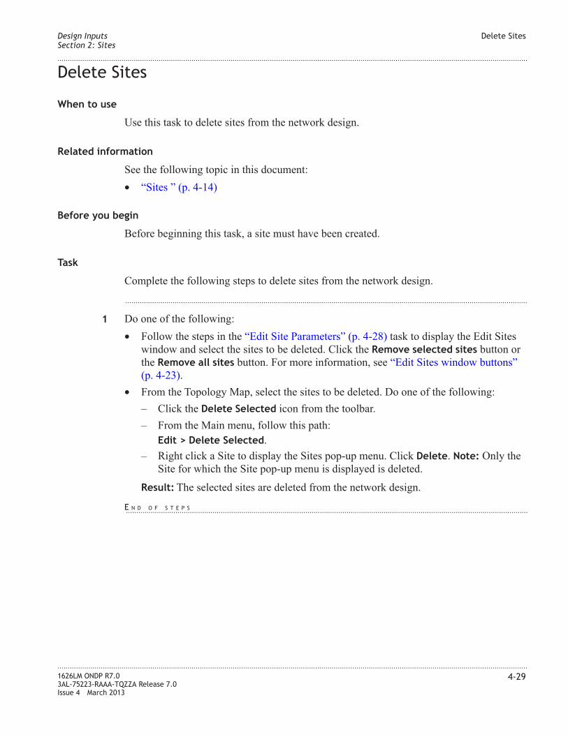
Delete Sites
When to use
Use this task to delete sites from the network design.
Related information
See the following topic in this document:
• “Sites ” (p. 4-14)
Before you begin
Before beginning this task, a site must have been created.
Task
Complete the following steps to delete sites from the network design.
...................................................................................................................................................................................................
1 Do one of the following:
• Follow the steps in the “Edit Site Parameters” (p. 4-28) task to display the Edit Sites
window and select the sites to be deleted. Click the Remove selected sites button or
the Remove all sites button. For more information, see “Edit Sites window buttons”
(p. 4-23).
• From the Topology Map, select the sites to be deleted. Do one of the following:
– Click the Delete Selected icon from the toolbar.
– From the Main menu, follow this path:
Edit > Delete Selected.
– Right click a Site to display the Sites pop-up menu. Click Delete. Note: Only the
Site for which the Site pop-up menu is displayed is deleted.
Result: The selected sites are deleted from the network design.
Design Inputs
Section 2: Sites
Delete Sites
....................................................................................................................................................................................................................................
....................................................................................................................................................................................................................................
1626LM ONDP R7.0
3AL-75223-RAAA-TQZZA Release 7.0
Issue 4 March 2013
4-29
E N D O F S T E P S...................................................................................................................................................................................................

Section 3: ILAs
Overview
Purpose
This section provides information on ILA sites.
Contents
ILAs 4-31
Change ILA Site Name 4-34
Design Inputs
Section 3: ILAs
Overview
....................................................................................................................................................................................................................................
....................................................................................................................................................................................................................................
4-30 1626LM ONDP R7.0
3AL-75223-RAAA-TQZZA Release 7.0
Issue 4 March 2013

ILAs
ILAs
The next step in network planning and design is to consider renaming ILA site names.
ILAs are automatically created by ONDP as a result of running the links design. The
following are the types of ILA sites that ONDP creates:
• ILA AGE site – A site which contains only one NE. This NE is connected by two links
and is used to correct the wavelengths tilt. This site is transparent. A user is not able to
create this site. This type of site is automatically inserted during the links design step.
• ILA PGE site – when designing APA networks. In this case, utilize a point to point
network with fixed nodes containing 16 spans.
• ILA – the ILA site is a simple amplifier, which is not visible on the Network Map, but
does appear in the list of ILAs in the Edit ILAs window.
For information on how to perform tasks related to ILAs, see
• “Change ILA Site Name” (p. 4-34) – to change the ILA site name
• “Edit NE Configuration” (p. 4-26) – to change the label of the ILA AGE/PGE site
• “Edit Site Parameters” (p. 4-28) – to change editable ILA AGE/PGE parameters
Edit ILAs window
The Edit ILAs window displays a list of ILA and Bypass sites. When the ILA Label or
NE Label are changed in this window, the modification is reflected the Edit Spans
window. Note: To change the name of an ILA site, use the Edit ILAs window and modify
the specific ILA Label.
To access the Edit ILAs window, follow this menu path: Inputs > Edit ILAs
Figure 4-8 Edit ILAs window
Design Inputs
Section 3: ILAs
ILAs
....................................................................................................................................................................................................................................
....................................................................................................................................................................................................................................
1626LM ONDP R7.0
3AL-75223-RAAA-TQZZA Release 7.0
Issue 4 March 2013
4-31

ILA parameters
Editable ILA parameters are indicated by a plus sign (+) appearing before the parameter
title. These parameters can be edited by double clicking the field and entering the value in
the Edit ILA window. To change a field, press the Tab key or click in a different field.
Warning: Interaction occurs between the Edit ILAs window, the Spans window and Sites
window, as well as other affected windows and reports throughout the tool. For example,
if the ILA Label is changed in the Spans table of the Edit Spans window, the ILA name
will change in the affected fields in the Spans table, the Edit ILAs window, and all other
windows and reports in which ILA Site Label is contained.
Table 4-7 ILA parameters
Parameter Definition Default value
Steps The step of the
incremental design in
which the link was
created
S0. For more information on incremental
design, see “Incremental Design” (p. 4-6).
+ILA Label Name to identify the
ILA site
System generated.
Note: This field changes what is contained in
the Site Label field on the Spans window and
all other related windows, fields, and reports.
NE Type Identifies the type of
NE
System generated. Possible values are ILA or
Bypass. This label is presented on the
dispersion graph. For more information see,
Figure 6-4, “Dispersion Map window”
(p. 6-9).
+NE Label Name to identify the
NE
System generated. User is able to edit this field
as required.
+Country None
Note: Entering a valid city name as the Site
Label automatically populates the country.
This feature currently supports selected cities
in France and Spain.
Edit ILAs Pop-up Menu
The Edit ILAs window contains a pop-up menu that offers additional actions to configure
ILAs. To access this menu, right click in any field in the Edit ILAs window.
Design Inputs
Section 3: ILAs
ILAs
....................................................................................................................................................................................................................................
....................................................................................................................................................................................................................................
4-32 1626LM ONDP R7.0
3AL-75223-RAAA-TQZZA Release 7.0
Issue 4 March 2013

The following table describes the options in the Edit ILAs window pop-up menu.
Table 4-8 Edit ILAs window pop-up menu
Option Description
Undo Undo the last action performed
Redo Redo the last action that was undone
Copy Selected Cells Copy the highlighted cells to the clipboard
Paste Cells Paste the copied cells at the cursor insertion point
Select All Select all sites in the table
Deselect All Clear all previously selected sites.
Figure 4-9 Edit ILAs window pop-up menu
Design Inputs
Section 3: ILAs
ILAs
....................................................................................................................................................................................................................................
....................................................................................................................................................................................................................................
1626LM ONDP R7.0
3AL-75223-RAAA-TQZZA Release 7.0
Issue 4 March 2013
4-33

Change ILA Site Name
When to use
Use this task to change the name that ONDP has assigned to an ILA site to a user-defined
site name.
This task is divided into 2 methods:
• “Method 1: Change ILA Site Name for ILA_AGE/ILA_PGE Sites” (p. 4-34)
• “Method 2: Change ILA Site Name for ILA/Bypass Sites” (p. 4-35)
Related information
See the following topic in this document:
• “ILAs” (p. 4-31)
Before you begin
Before beginning this task, the ILA site must have been created by ONDP.
Method 1: Change ILA Site Name for ILA_AGE/ILA_PGE Sites
Complete the following steps to change ILA site name for ILA_AGE/ILA_PGE sites.
...................................................................................................................................................................................................
1 Do one of the following:
• From the “Edit Sites window” (p. 4-20), double click on the Site Label field for the
desired ILA_AGE/ILA_PGE, and enter the new ILA name.
• From the “Edit NE window” (p. 4-18), change the name of the ILA_AGE/ILA_PGE
in the Label field.
Result: The selected ILA_AGE/ILA_PGE site names are changed in all related
ONDP fields and reports.
Design Inputs
Section 3: ILAs
Change ILA Site Name
....................................................................................................................................................................................................................................
....................................................................................................................................................................................................................................
4-34 1626LM ONDP R7.0
3AL-75223-RAAA-TQZZA Release 7.0
Issue 4 March 2013
E N D O F S T E P S...................................................................................................................................................................................................

Method 2: Change ILA Site Name for ILA/Bypass Sites
Complete the following steps to the change ILA site name for ILA/Bypass sites.
...................................................................................................................................................................................................
1 Do one of the following:
• From the “Edit ILAs window” (p. 4-31), double click on the ILA Label field and enter
the new ILA/Bypass site name.
• From the “Edit Spans window” (p. 4-37) window, double click in either the NE name
before span field, or the NE name after span field and enter the new ILA/Bypass
site name.
Result: The selected ILA/Bypass site names are changed in all related ONDP fields
and reports.
Design Inputs
Section 3: ILAs
Change ILA Site Name
....................................................................................................................................................................................................................................
....................................................................................................................................................................................................................................
1626LM ONDP R7.0
3AL-75223-RAAA-TQZZA Release 7.0
Issue 4 March 2013
4-35
E N D O F S T E P S...................................................................................................................................................................................................

Section 4: Links and Spans
Overview
Purpose
This section provides information on how to create, view, and edit links and spans.
Contents
Links and Spans 4-37
Create Links and Spans 4-46
Edit Links and Spans 4-47
Add Spans to Links 4-48
Change Span Parameters and Copy to a New Span 4-50
Merge Spans 4-52
Delete Links and Spans 4-54
Identify a Link on the Map 4-55
Design Inputs
Section 4: Links and Spans
Overview
....................................................................................................................................................................................................................................
....................................................................................................................................................................................................................................
4-36 1626LM ONDP R7.0
3AL-75223-RAAA-TQZZA Release 7.0
Issue 4 March 2013

Links and Spans
Links and Spans
The next step in network planning and design is to consider the links between the sites.
For information on how to perform tasks related to links and spans, see the following:
• “Create Links and Spans” (p. 4-46)
• “Edit Links and Spans” (p. 4-47)
• “Add Spans to Links” (p. 4-48)
• “Delete Links and Spans” (p. 4-54)
• “Identify a Link on the Map” (p. 4-55)
Edit Spans window
The Edit Spans window is used to configure link details and the span details associated
with the links. The window is divided into two sections: Links and Spans. When a link is
selected from the Links section, the spans associated with the link are displayed in the
Spans section. Interaction occurs between the Links table and the Spans table. Changing a
parameter in one table can affect the parameters in the other. For example, if the Spans
Count is changed in the Links table, the spans for the link are redefined in the Spans
table.
Figure 4-10 Edit Spans window
Design Inputs
Section 4: Links and Spans
Links and Spans
....................................................................................................................................................................................................................................
....................................................................................................................................................................................................................................
1626LM ONDP R7.0
3AL-75223-RAAA-TQZZA Release 7.0
Issue 4 March 2013
4-37

Links Pop-up Menu
The Edit Spans window contains two pop-up menus that offer additional actions to
configure links and spans parameters: the Links pop-up menu and the Spans pop-up
menu. To access the Links pop-up menu, right click any field in the Links table.
The following table describes the options in the Links table pop-up menu.
Table 4-9 Links table pop-up menu
Option Description
Undo Undo the last action
Redo Redo the last action
Copy Selected Cells Copy selected cells to the clip board
Paste Cells Paste the copied cells at the cursor insertion point
Select All Select all links on the map
Deselect All Clear all previously selected links.
Highlight All Selected on Map Highlight the links that are selected on the Map in the
Links table
Design Selected Links Run the design process for selected links.
Show/Tune Design Results Opens the Edit route optical design window which displays
the results of the design and allows the design to be
changed. For more information, see “Show/Tune Selected
Links Design ” (p. 6-3).
Figure 4-11 Links table pop-up menu
Design Inputs
Section 4: Links and Spans
Links and Spans
....................................................................................................................................................................................................................................
....................................................................................................................................................................................................................................
4-38 1626LM ONDP R7.0
3AL-75223-RAAA-TQZZA Release 7.0
Issue 4 March 2013

Table 4-9 Links table pop-up menu (continued)
Option Description
Show Physical Diagnostics Opens a window which allows you to toggle between the
Dispersion Map and Optical design results for a design. For
more information, see “Show Selected Links Physical
Diagnostics” (p. 6-6).
Show Real-Time Fast Feasibility
Criteria
Opens the FFC window. If the optical inputs change, the
Fast Feasibility Criteria (FFC) value displays the optical
feasibility of links between nodes and is recalculated. For
more information, see “Show Selected Links Real-Time
Fast Feasibility Criteria” (p. 6-15).
Links parameters
Editable link parameters are indicated by a plus sign (+) appearing before the parameter
title. These parameters can be edited by double clicking the field and entering the value in
the Edit Spans window. To change a field, press the Tab key or click in a different field.
Additional entry methods are indicated in the following tables.
Warning: Interaction occurs between the Links table and the Spans table. Changing a
parameter in one table can affect the parameters in the other. For example, if the Spans
Count is changed in the Links table, the spans for the link are redefined in the Spans
table.
Table 4-10 Links parameters
Parameter Definition Default value
Steps The step of the
incremental design in
which the link was
created
S0. For more information on incremental
design, see “Incremental Design” (p. 4-6).
Source Site Identifies the
origination site of the
link
(varies)
Destination Site Identifies the end site
of the link
(varies)
Sibling Label Differentiates two
links from the same
source to the same
destination
Empty, A, B, C, D, ...
Design Inputs
Section 4: Links and Spans
Links and Spans
....................................................................................................................................................................................................................................
....................................................................................................................................................................................................................................
1626LM ONDP R7.0
3AL-75223-RAAA-TQZZA Release 7.0
Issue 4 March 2013
4-39

Table 4-10 Links parameters (continued)
Parameter Definition Default value
+Link name Name for the OMS Default value: [Source Site name] [Destination
Site name] [Sibling Label if not empty].
Editable field. Any string of characters
allowed except strings containing /. /, [. ]. *, ?.
+Fiber Type Identifies the type of
fiber
Possible values are: SMF (default), E-leaf,
TWRS, and DSF. Mixed fiber type is
automatically generated; it is not an entry
available to the user. For more information,
see “Mixed fiber type with DSF” (p. 4-41).
+Subset Identifies the name of
the subset to which
this link belongs
Select the subset from the pull down list, or
accept the default. For more information on
subsets, see “Section 6: Optical Subsets”
(p. 4-88).
+Spans Count Sets the number of
spans in the link
1
+Length [km] Sets the length in
[km] of the link.
Represents the total
length of all the spans
in the link.
100. This field is interactive with the Length
fields in the Spans table. Changing the value
in this parameter changes the value in the
Length parameter in the Spans table. Adding
spans to the link increases the value of this
field. For more information, see “Mixed fiber
type with DSF” (p. 4-41).
+Lineic Loss
[dB/km]
Ratio between the
loss and the length
+Loss [dB] Sets the loss in dB of
the span
22
Sets the loss of the link. Represents the total
losses of all the spans in the link.
+BOL/EOL Loss
Margin
Beginning of
Life/End of Life loss
margin.
1
PMD [ps] Polarization Mode
Dispersion
1. This field is the result of the calculation
coming from the spans. Each span brings a
PMDi per span equal to the square root of
Length * PMDi coefficient. The total PMD is
calculated by: PMD 2=Sum for each span
PMDi 2 per span. In this example, only one
span exists, therefore the square root of 100 =
10 multiplied by 0.1 leads to 1 ps.
Design Inputs
Section 4: Links and Spans
Links and Spans
....................................................................................................................................................................................................................................
....................................................................................................................................................................................................................................
4-40 1626LM ONDP R7.0
3AL-75223-RAAA-TQZZA Release 7.0
Issue 4 March 2013

Table 4-10 Links parameters (continued)
Parameter Definition Default value
+Administrative Cost User-defined entry
which assigns a cost
to the routing. A
lower cost gives
preference to the
path. This field is
used for RWA
optimization.
1
+Computation Mode Used to define how
the audit process is
controlled on this
resource. Possible
values are:
Automatic,
Semi-Auto, Manual,
or NLP/OSNR
Automatic
For more information, see “Set Computation
Mode parameter” (p. 7-4)
Mixed fiber type with DSF
If an OMS contains mixed fibers types with at least one DSF, there is a restriction on the
length of the other fiber type. The following table lists the maximum length (km)
authorized for the other fiber type, to prevent exceeding the dispersion limit.
Table 4-11 Mixed fiber types with DSF length restriction
SMF E-LEAF TW-RS TeraLight
10G NRZ 33 94 102 62
40G P-PDSK 54 156 170 103
Links table buttons
The Links table in the Edit Spans window contains buttons which perform the following
actions.
Table 4-12 Links table button actions
Button Tool tip Description
Remove selected link Delete the highlighted links from the
network design.
Design Inputs
Section 4: Links and Spans
Links and Spans
....................................................................................................................................................................................................................................
....................................................................................................................................................................................................................................
1626LM ONDP R7.0
3AL-75223-RAAA-TQZZA Release 7.0
Issue 4 March 2013
4-41

Table 4-12 Links table button actions (continued)
Button Tool tip Description
Remove all links Delete all links from the network design.
Spans Pop-up Menu
The Edit Spans window contains two pop-up menus that offer additional actions to
configure links and spans parameters: the Links pop-up menu and the Spans pop-up
menu. To access the Spans pop-up menu, right click any field in the Spans table.
The following table describes the options in the Spans pop-up menu.
Table 4-13 Spans table pop-up menu
Option Description
Undo Undo the last action
Redo Redo the last action
Copy Selected Cells Copy selected cells to the clip board
Paste Cells Paste the copied cells at the cursor insertion point
Select All Select all links on the map
Deselect All Clear all previously selected links.
Figure 4-12 Spans table pop-up menu
Design Inputs
Section 4: Links and Spans
Links and Spans
....................................................................................................................................................................................................................................
....................................................................................................................................................................................................................................
4-42 1626LM ONDP R7.0
3AL-75223-RAAA-TQZZA Release 7.0
Issue 4 March 2013

Table 4-13 Spans table pop-up menu (continued)
Option Description
Copy Span to Add Model Copies all of the parameters of the selected span to the Add
Span tool tip. The parameters are displayed on the Add
Span tool tip. To add a span with the copied parameters,
click the Add Span button. For more information, see
“Change Span Parameters and Copy to a New Span”
(p. 4-50).
Copy Cell to Add Model Copies the parameters of the selected cell to the Add Span
tool tip. The copied parameters are displayed on the Add
Span tool tip. To add a span with the copied parameters,
click the Add Span button. For more information, see
“Change Span Parameters and Copy to a New Span”
(p. 4-50).
Merge Selected Spans Merges a set of selected contiguous spans. The result is a
single span with the characteristics of the selected spans.
For more information, see “Merge Spans” (p. 4-52).
Spans parameters
Editable span parameters are indicated by a plus sign (+) before the parameter title. These
parameters can be edited by double clicking the field and entering the value in the Edit
Spans window. To see a change in a field, press the Tab key or click in a different field.
Additional entry methods are indicated in the following tables.
Warning: Interaction occurs between the Links table and the Spans table. Changing a
parameter in one table can affect the parameters in the other. For example, if the Spans
Count is changed in the Links table, the spans for the link are redefined in the Spans
table.
Table 4-14 Span parameters
Parameter Definition Default value
Steps The step of the
incremental design in
which the span was
created.
S0. For more information on incremental
design, see “Incremental Design” (p. 4-6).
+Order Order in which the
span displays in the
table
(varies)
Design Inputs
Section 4: Links and Spans
Links and Spans
....................................................................................................................................................................................................................................
....................................................................................................................................................................................................................................
1626LM ONDP R7.0
3AL-75223-RAAA-TQZZA Release 7.0
Issue 4 March 2013
4-43

Table 4-14 Span parameters (continued)
Parameter Definition Default value
+NE name before
span
Site, ILA, or Bypass
before the span in the
considered direction
Editable field. Any string of characters
allowed except strings containing /. /, [. ]. *, ?.
Default value is the name of the Site, ILA, or
Bypass that is located at the beginning of the
span.
+NE name after span Site, ILA, or Bypass
after the span in the
considered direction
Editable field. Any string of characters
allowed except strings containing /. /, [. ]. *, ?.
Default value is the name of the Site, ILA, or
Bypass that is located at the end of the span.
+Span name Name for the OTS Default value: [Source name] [Destination
name]. Editable field. Any string of characters
allowed.
Default value definitions:
• Source name – site or ILA before the span
in the considered direction
• Destination name – site or ILA after the
span in the considered direction
+Fiber Type Identifies the type of
fiber
Possible values are: SMF (default), E-leaf,
TWRS, and DSF
+Length [km] Sets the length in
[km] of the span.
This field is interactive with the Length and
Spans Count fields in the Links table. The
value in this field is the length of the link
divided by the number of spans. Changing the
value in this parameter changes the value in
the Length parameter in the Links table.
+BOL Lineic Loss
[dB/km]
Ratio between the
loss and the length
0.22. This field changes when the Length field
is changed.
+ BOL Loss [dB] Sets the Beginning of
Life loss in dB of the
span
22
PMD Coefficient
[ps/sqrt(km)]
Polarization - Mode
Dispersion
0.1
Design Inputs
Section 4: Links and Spans
Links and Spans
....................................................................................................................................................................................................................................
....................................................................................................................................................................................................................................
4-44 1626LM ONDP R7.0
3AL-75223-RAAA-TQZZA Release 7.0
Issue 4 March 2013

Spans table buttons
The Spans table in the Edit Spans window contains buttons which perform the following
actions.
Table 4-15 Spans table button actions
Button Tool tip Description
Add a span with the specified parameters to
the link. The tool tip displays the parameters
of the span that is added.
For more information on how to change the
parameter information before adding the
span, see “Change Span Parameters and Copy
to a New Span” (p. 4-50)
Remove selected
spans
Delete the highlighted spans from the link.
Remove all spans
but one
Delete all spans but one from the link.
Design Inputs
Section 4: Links and Spans
Links and Spans
....................................................................................................................................................................................................................................
....................................................................................................................................................................................................................................
1626LM ONDP R7.0
3AL-75223-RAAA-TQZZA Release 7.0
Issue 4 March 2013
4-45

Create Links and Spans
When to use
Use this task to create a link. When a link is created between two sites, a span is also
automatically created.
Related information
See the following topic in this document:
• “Links and Spans” (p. 4-37)
Before you begin
This task does not have any preconditions.
Task
Complete the following steps to create a link.
...................................................................................................................................................................................................
1 Do one of the following:
• Select the Create Link icon on the Topology Map toolbar.
• Right click the site to display the Site pop-up menu. From the Site pop-up menu,
select Create Link.
...................................................................................................................................................................................................
2 On the Topology Map, click the Site from which the link originates and drag the cursor to
the site on which the link terminates.
Result: A blue line representing a link is created between the sites. A single span for
the link is automatically created.
Design Inputs
Section 4: Links and Spans
Create Links and Spans
....................................................................................................................................................................................................................................
....................................................................................................................................................................................................................................
4-46 1626LM ONDP R7.0
3AL-75223-RAAA-TQZZA Release 7.0
Issue 4 March 2013
E N D O F S T E P S...................................................................................................................................................................................................

Edit Links and Spans
When to use
Links and spans are viewable and editable from the Edit Spans window. Use this task to
view and edit links and spans.
Warning: Interaction occurs between the Links table and the Spans table. Changing a
parameter in one table can affect the parameters in the other. For example, if the Spans
Count is changed in the Links table, the spans for the link are redefined in the Spans
table.
Related information
See the following topic in this document:
• “Links and Spans” (p. 4-37)
Before you begin
To complete this task, a link must be created.
Task
Complete the following steps to view and edit links and spans.
...................................................................................................................................................................................................
1 Display the Edit Spans window by doing one of the following:
• From the Topology Map Main menu, follow this path:
Inputs > Edit Links/Spans
• Right click a link on the Topology Map. From the Link pop-up menu, select Highlight
in Table.
Result: The Edit Spans window is displayed. Links that are selected on the Topology
Map are highlighted in the table. For an illustration of the Edit Spans window, see
Figure 4-10, “Edit Spans window” (p. 4-37).
...................................................................................................................................................................................................
2 Edit the link/span parameters. For a description of the link parameters, see Table 4-10,
“Links parameters” (p. 4-39). For a description of the span parameters, see Table 4-14,
“Span parameters” (p. 4-43).
Result: The links and spans are changed.
Design Inputs
Section 4: Links and Spans
Edit Links and Spans
....................................................................................................................................................................................................................................
....................................................................................................................................................................................................................................
1626LM ONDP R7.0
3AL-75223-RAAA-TQZZA Release 7.0
Issue 4 March 2013
4-47
E N D O F S T E P S...................................................................................................................................................................................................

Add Spans to Links
When to use
Use this task to add spans to links.
Warning: Interaction occurs between the Links table and the Spans table. Changing a
parameter in one table can affect the parameters in the other. For example, if the Spans
Count is changed in the Links table, the spans for the link are redefined in the Spans
table.
Note: When spans are added to a link, ONDP automatically creates ILA or Bypass sites
between the spans. Once created, ILA or Bypass sites are displayed in the Edit ILAs
window. For more information, see “Edit ILAs window” (p. 4-31).
Related information
See the following topic in this document:
• “Links and Spans” (p. 4-37)
Before you begin
This task does not have any preconditions.
Task
Complete the following steps to add spans to links.
...................................................................................................................................................................................................
1 Follow the first step in the “Edit Links and Spans” (p. 4-47) to display the Edit Spans
window.
Result: The Edit Spans window is displayed.
...................................................................................................................................................................................................
2 Click the link to which spans will be added.
Result: The link is selected and the spans in the link are displayed in the Spans table.
...................................................................................................................................................................................................
3 Do one of the following to add spans to the selected link.
• In the Links table, click in the Spans Count field and enter the number of spans.
• In the Spans table, mouse over the Add Span button on the left side of the table. If the
Span parameters are correct, click the Add Span button.
Note: The Add Span button tool tip displays the parameters of the Span that will be
added. To change the parameters of a span and copy them to a new span, see “Change
Span Parameters and Copy to a New Span” (p. 4-50).
Design Inputs
Section 4: Links and Spans
Add Spans to Links
....................................................................................................................................................................................................................................
....................................................................................................................................................................................................................................
4-48 1626LM ONDP R7.0
3AL-75223-RAAA-TQZZA Release 7.0
Issue 4 March 2013

Result: Spans are added to the link and the associated parameters are redefined in the
tables.
Design Inputs
Section 4: Links and Spans
Add Spans to Links
....................................................................................................................................................................................................................................
....................................................................................................................................................................................................................................
1626LM ONDP R7.0
3AL-75223-RAAA-TQZZA Release 7.0
Issue 4 March 2013
4-49
E N D O F S T E P S...................................................................................................................................................................................................

Change Span Parameters and Copy to a New Span
When to use
Use this task to Change Span Parameters and Copy to a New Span.
Warning: Interaction occurs between the Links table and the Spans table. Changing a
parameter in one table can affect the parameters in the other. For example, if the Spans
Count is changed in the Links table, the spans for the link are redefined in the Spans
table.
Related information
See the following topic in this document:
• “Links and Spans” (p. 4-37)
Before you begin
This task does not have any preconditions.
Change Span Parameters and Copy to a New Span
Complete the following steps to change the span information displayed in the Add Span
button tool tip and copy to a new span.
...................................................................................................................................................................................................
1 Follow the first step in the “Edit Links and Spans” (p. 4-47) to display the Edit Spans
window.
Result: The Edit Spans window is displayed.
...................................................................................................................................................................................................
2 Click the link to which spans will be added.
Result: The link is selected and the spans in the link are displayed in the Spans table.
...................................................................................................................................................................................................
3 From the Spans table, select the Span to copy.
...................................................................................................................................................................................................
4 Do one of the following:
• To copy all the span parameters to the Add Span button tool tip, right click in the table
to display the Spans table pop-up menu, and select Copy Span to Add Model.
• To change a parameter in the span, edit the span parameter, right click in the table to
display the Spans table pop-up menu, and select Copy Cell to Add Model.
Design Inputs
Section 4: Links and Spans
Change Span Parameters and Copy to a New Span
....................................................................................................................................................................................................................................
....................................................................................................................................................................................................................................
4-50 1626LM ONDP R7.0
3AL-75223-RAAA-TQZZA Release 7.0
Issue 4 March 2013

Result: The Span parameter information is changed in the Add Span button tool tip.
To view the change applied to the Add Model, mouse over the Add Span button for at
least one second.
...................................................................................................................................................................................................
5 Click the Add Span button.
Result: The new span is added to the table below the selected row.
Design Inputs
Section 4: Links and Spans
Change Span Parameters and Copy to a New Span
....................................................................................................................................................................................................................................
....................................................................................................................................................................................................................................
1626LM ONDP R7.0
3AL-75223-RAAA-TQZZA Release 7.0
Issue 4 March 2013
4-51
E N D O F S T E P S...................................................................................................................................................................................................

Merge Spans
When to use
Use this task to merge spans.
Warning: Interaction occurs between the Links table and the Spans table. Changing a
parameter in one table can affect the parameters in the other. For example, if the Spans
Count is changed in the Links table, the spans for the link are redefined in the Spans
table.
Related information
See the following topic in this document:
• “Links and Spans” (p. 4-37)
Before you begin
To merge spans, the spans must be compatible. Merged spans must have the same type
(SMF, LEAF, TWRS, or DSF).
Task
Complete the following steps to add merge spans.
...................................................................................................................................................................................................
1 Follow the first step in the “Edit Links and Spans” (p. 4-47) to display the Edit Spans
window.
Result: The Edit Spans window is displayed.
...................................................................................................................................................................................................
2 Click the link on which spans will be merged.
Result: The link is selected and the spans in the link are displayed in the Spans table.
...................................................................................................................................................................................................
3 Select the spans to merge. To select multiple spans, hold the Shift key while selecting
spans. Note: Spans must be contiguous.
Result: Selected spans are highlighted in the table.
...................................................................................................................................................................................................
4 Right click the Spans table to display the Spans table pop-up menu.
...................................................................................................................................................................................................
5 From the Spans table pop-up menu, select Merge Selected Cells.
Design Inputs
Section 4: Links and Spans
Merge Spans
....................................................................................................................................................................................................................................
....................................................................................................................................................................................................................................
4-52 1626LM ONDP R7.0
3AL-75223-RAAA-TQZZA Release 7.0
Issue 4 March 2013

Result: The selected spans are merged into a single span containing the characteristics
from the merged cells.
Note: Once spans are merged, some ILA or Bypass sites between them are deleted.
This can be seen in the Edit ILAs window. For more information, see “Edit ILAs
window” (p. 4-31).
Design Inputs
Section 4: Links and Spans
Merge Spans
....................................................................................................................................................................................................................................
....................................................................................................................................................................................................................................
1626LM ONDP R7.0
3AL-75223-RAAA-TQZZA Release 7.0
Issue 4 March 2013
4-53
E N D O F S T E P S...................................................................................................................................................................................................

Delete Links and Spans
When to use
Use this task to delete links and spans from the network design.
Related information
See the following topic in this document:
• “Links and Spans” (p. 4-37)
Before you begin
This task does not have any preconditions.
Task
Complete the following steps to delete links or spans from the network design.
...................................................................................................................................................................................................
1 Do one of the following:
• Follow the first step in the “Edit Links and Spans” (p. 4-47) task to display the Edit
Spans window and select the links or spans to be deleted. Do one of the following:
– Click the Remove selected links or the Remove selected spans button.
– From the Links table, select the Remove all links button.
– From the Spans table, select the Remove all spans but one button.
• From the Topology Map, select the links to be deleted. Do one of the following:
– Click the Delete Selected icon from the toolbar.
– From the Main menu, follow this path:
Edit > Delete Selected.
– Right click the Map and select Delete All Selected from the Map pop-up menu.
Result: The links and spans are deleted.
Note: If a link is deleted, all ILAs and Bypass sites on the link are deleted. If a
span is deleted, the corresponding ILA or Bypass sites are deleted.
Design Inputs
Section 4: Links and Spans
Delete Links and Spans
....................................................................................................................................................................................................................................
....................................................................................................................................................................................................................................
4-54 1626LM ONDP R7.0
3AL-75223-RAAA-TQZZA Release 7.0
Issue 4 March 2013
E N D O F S T E P S...................................................................................................................................................................................................

Identify a Link on the Map
When to use
Use this task to identify a link on the Map.
Related information
See the following topic in this document:
• “Links and Spans” (p. 4-37)
Before you begin
Before beginning this task, a link must be created.
Task
Complete the following steps to identify links on the Map.
...................................................................................................................................................................................................
1 Follow the first step in the “Edit Links and Spans” (p. 4-47) task to display the Edit Spans
window.
Result: The Edit Spans window is displayed.
...................................................................................................................................................................................................
2 Select a link by clicking the link row. Multiple links can be selected by holding the [Shift]
key while selecting links.
Result: The links are selected.
...................................................................................................................................................................................................
3 Right click in the Edit Spans window.
Result: The Links pop-up window is displayed.
...................................................................................................................................................................................................
4 From the Links pop-up window, select Highlight All Selected on Map.
Result: The selected links are highlighted on the Topology Map.
Design Inputs
Section 4: Links and Spans
Identify a Link on the Map
....................................................................................................................................................................................................................................
....................................................................................................................................................................................................................................
1626LM ONDP R7.0
3AL-75223-RAAA-TQZZA Release 7.0
Issue 4 March 2013
4-55
E N D O F S T E P S...................................................................................................................................................................................................

Section 5: Relations and Services
Overview
Purpose
This section provides information on how to create, view, and edit relations and services.
Contents
Relations and Services 4-57
Create a Relation 4-78
Edit Relations and Services 4-79
Create Services 4-80
Change Service Parameters and Copy to a New Service 4-82
Delete Relations and Services 4-84
Identify a Relation on the Map 4-85
Edit Spatial and Spectral Constraints 4-86
Design Inputs
Section 5: Relations and Services
Overview
....................................................................................................................................................................................................................................
....................................................................................................................................................................................................................................
4-56 1626LM ONDP R7.0
3AL-75223-RAAA-TQZZA Release 7.0
Issue 4 March 2013

Relations and Services
Relations and Services
The next step in network planning and design is to consider the traffic matrix. In ONDP,
this step is accomplished through relations and services.
For information on how to perform tasks related to relations and services, see the
following:
• “Create a Relation” (p. 4-78)
• “Edit Relations and Services” (p. 4-79)
• “Create Services” (p. 4-80)
• “Delete Relations and Services” (p. 4-84)
• “Identify a Relation on the Map” (p. 4-85)
• “Edit Spatial and Spectral Constraints” (p. 4-86)
Routing constraints
The use of spectral and spacial routing constraints enables the user to impact the Routing
and Wavelength Allocation (RWA) of services. It is possible to specify both the path
(spatial constraint) and the wavelength (spectral constraint). For more information, see
“Edit Spectral Constraint window” (p. 4-74) and “Edit Spatial and Spectral Constraints”
(p. 4-86)
Most Disjoint feature
The Most disjoint feature is designed to release design constraints if no other solution is
available . This feature allows, under some conditions, infringement of disjointness rules.
To activate this feature, check the Most disjoint on links/nodes checkbox located on the
“Traffic Setting Design Parameters” (p. 4-122).
Edit Services window
The Edit Services window is used to configure relations details and the services details
associated with the relations. The window is divided into two sections: Relations and
Services. When a relation is selected from the Relations section, the services associated
with the relation are displayed in the Services section. Interaction occurs between the
Relations table and the Services table. Changing a parameter in one table can affect the
parameters in the other. For example, if the Services Count is changed in the Relations
table, the services for the relation is redefined in the Services table.
Design Inputs
Section 5: Relations and Services
Relations and Services
....................................................................................................................................................................................................................................
....................................................................................................................................................................................................................................
1626LM ONDP R7.0
3AL-75223-RAAA-TQZZA Release 7.0
Issue 4 March 2013
4-57

Relations Pop-up Menu
The Edit Services window contains two pop-up menus that offer additional actions to
configure relations and services parameters: the Relations table pop-up menu and the
Services table pop-up menu. To access the Relations table pop-up menu, right click any
field in the Relations table.
Figure 4-13 Edit Services window
Figure 4-14 Relations table pop-up menu
Design Inputs
Section 5: Relations and Services
Relations and Services
....................................................................................................................................................................................................................................
....................................................................................................................................................................................................................................
4-58 1626LM ONDP R7.0
3AL-75223-RAAA-TQZZA Release 7.0
Issue 4 March 2013

The following table describes the options in the Relations table pop-up menu.
Table 4-16 Relations table pop-up menu
Option Description
Undo Undo the last action
Redo Redo the last action
Copy Selected Cells Copy selected cells to the clip board
Paste Cells Paste the copied cells at the cursor insertion point
Select All Select all relations in the table
Deselect All Clear all previously selected relations.
Topo Highlight... Opens the Topo Highlight menu, which contains
commands to highlight relations on the Topology Map. For
more information, see Figure 4-15, “Topo Highlight... pop
up menu” (p. 4-60).
Freeze all Constraints [W+P] Prevents the RWA of all working and protecting paths from
changing
Freeze all Constraints [W+P]
Except Unprotected
Prevents the RWA of all working and protecting paths from
changing, except for unprotected paths.
Clear all [W] Constraints Clear the RWA for all working paths
Clear all [P] Constraints Clear the RWA for all protecting paths
Working [W] Constraints Opens the Working Constraints pop up menu, which
contains commands to create or edit the RWA for working
paths. For more information, see Figure 4-16, “Working
[W] Constraints pop up menu” (p. 4-60).
Protecting [P] Constraints Opens the Protecting Constraints pop up menu, which
contains commands to create or edit the RWA for
protecting paths. For more information, see Figure 4-17,
“Protecting [P] Constraints pop up menu” (p. 4-61)
Design Inputs
Section 5: Relations and Services
Relations and Services
....................................................................................................................................................................................................................................
....................................................................................................................................................................................................................................
1626LM ONDP R7.0
3AL-75223-RAAA-TQZZA Release 7.0
Issue 4 March 2013
4-59

The Topo Highlight... menu contains commands to highlight relations on the Topology
Map. To access this menu, right click in the Relations table, and from the Relations table
pop up menu, move the cursor to the Topo Highlight... command.
Option Description
Highlight All Selected on Map Highlight the relations that are selected in the
table on the Topology Map
Highlight All [W] Paths Highlights all working paths on the Map.
Highlight all [P] Paths Highlights all protecting paths on the Map.
Highlight all [W+P] Paths Highlights both working and protecting paths
on the Map.
The Working [W] Constraints pop up menu contains commands to create or edit
constraints on relations. To access this menu, right click in the Relations table, and from
the Relations table pop up menu, move the cursor to the Working [W] Constraints
command.
Table 4-17 Working [W] Constraints pop up menu
Option Description
Highlight [W] Path Constraints Highlight working path constraints on the
Topology Map
Figure 4-15 Topo Highlight... pop up menu
Figure 4-16 Working [W] Constraints pop up menu
Design Inputs
Section 5: Relations and Services
Relations and Services
....................................................................................................................................................................................................................................
....................................................................................................................................................................................................................................
4-60 1626LM ONDP R7.0
3AL-75223-RAAA-TQZZA Release 7.0
Issue 4 March 2013

Table 4-17 Working [W] Constraints pop up menu (continued)
Option Description
Freeze [W] Computed Path (Spatial Only) Prevent the computed spatial working path
from changing.
Freeze [W] Computed Path (Spatial +
Spectral)
Prevent the computed spatial and spectral
working path from changing.
Set [W] Path Constraints from Map Selection Set working path constraints selected on the
Topology Map
Clear [W] Constraints Clear all working path constraints.
The Protecting [P] Constraints pop up menu contains commands to create or edit
protecting constraints on relations. To access this menu, right click in the Relations table,
and from the Relations table pop up menu, move the cursor to the Protecting [W]
Constraints command.
Table 4-18 Protecting [P] Constraints pop up menu
Option Description
Highlight [P] Path Constraints Highlight protecting path constraints for
relations on the Topology Map
Freeze [P] Computed Path (Spatial Only) Prevent the computed spatial protecting path
from changing.
Freeze [P] Computed Path (Spatial + Spectral) Prevent the computed spatial and spectral
protecting path from changing.
Set [P] Path Constraints from Map Selection Set protecting path constraints for relations
selected on the Topology Map
Clear [P] Constraints Clear all protecting path constraints for
relations.
Figure 4-17 Protecting [P] Constraints pop up menu
Design Inputs
Section 5: Relations and Services
Relations and Services
....................................................................................................................................................................................................................................
....................................................................................................................................................................................................................................
1626LM ONDP R7.0
3AL-75223-RAAA-TQZZA Release 7.0
Issue 4 March 2013
4-61

Relations parameters
Editable relations parameters are indicated by a plus sign (+) before the parameter title.
These parameters can be edited by double clicking the field and entering the value in the
field. After changing the field value, press the Tab key or click in a different field.
Additional entry methods are indicated in the following tables.
Table 4-19 Relations parameters
Parameter Definition Default value
Steps The step of the
incremental design in
which the relation
was created.
S0. For more information on incremental
design, see “Incremental Design” (p. 4-6).
Source Site Identifies the
origination site of the
relation
(varies)
Destination Site Identifies the end site
of the relation
(varies)
Sibling Label Differentiates two
links from the same
source to the same
destination
Empty, A or B
+Client Traffic Sets the client side
board for the relation
Allowable values are defined in the
Transponder Bitrate and Encoding fields on
the Set Design Parameters window,
corresponding to the line side. The default is
defined by the value set in the TrxA field.
To change the Client Traffic field double click
the field and select from the list. For more
information, see “Setting Client Traffic,
Concentration, and OCH Line fields”
(p. 4-63).
+Concentration Sets the type of
concentration for the
relation
None.
Allowable values are determined by the Client
Traffic and Transponder Bitrate and
Encoding fields. Only allowable values are
displayed.
To change the Concentration field double
click the field and select from the list. For
more information, see “Setting Client Traffic,
Concentration, and OCH Line fields”
(p. 4-63).
Design Inputs
Section 5: Relations and Services
Relations and Services
....................................................................................................................................................................................................................................
....................................................................................................................................................................................................................................
4-62 1626LM ONDP R7.0
3AL-75223-RAAA-TQZZA Release 7.0
Issue 4 March 2013

Table 4-19 Relations parameters (continued)
Parameter Definition Default value
+OCH Line Sets the OCH line
type of this relation
Allowable values are determined by the values
set in the Client Traffic, Transponder Bitrate
and Encoding, and Concentration fields.
To change the OCH Line field double click the
field and select from the list. For more
information, see “Setting Client Traffic,
Concentration, and OCH Line fields”
(p. 4-63).
+Protection Type Sets the protection of
the relation
Unprotected
Select the Protection Type from the list by
double clicking in the field. Changing this
field changes the Protection Type of all the
service in the relation. Possible values are:
Unprotected, Protection 1 + 1, Restoration
SBR or Restoration PRC.
+Disjointness Sets disjoint
condition for diverse
path routing
Varies, based on the value selected in the
Protection Type field. Affects the routing of
unprotected and SBR services. Services can
have the same sources and destinations or
different sources and destinations.
+Services Count Sets the number of
services in the
relation
1
Capacity [Mb/s] Identifies the capacity
in [Mb/s] of the
relation. Represents
the total capacity of
all the services in the
relation.
Varies, based on the values in the Service
Type and Service Count fields.
Setting Client Traffic, Concentration, and OCH Line fields
The values in the Client Traffic, Concentration, and OCH Line fields interact with each
other and also interact with the services in the relation. Based on the changes made, the
values in the Client Traffic, Concentration, and OCH Line fields may change, and the
possible options available for selection in these fields may change, in both the Relations
table and the Services table.
Design Inputs
Section 5: Relations and Services
Relations and Services
....................................................................................................................................................................................................................................
....................................................................................................................................................................................................................................
1626LM ONDP R7.0
3AL-75223-RAAA-TQZZA Release 7.0
Issue 4 March 2013
4-63

Relations table buttons
The Relations table in the Edit Services window contains buttons which perform the
following actions.
Table 4-20 Relations table button actions
Button Tool tip Description
Remove selected
relations
Delete the highlighted relations from the
network design.
Remove all relations Delete all relations from the network design.
Design Inputs
Section 5: Relations and Services
Relations and Services
....................................................................................................................................................................................................................................
....................................................................................................................................................................................................................................
4-64 1626LM ONDP R7.0
3AL-75223-RAAA-TQZZA Release 7.0
Issue 4 March 2013

Services Pop-up Menu
The Edit Services window contains two pop-up menus that offer additional actions to
configure relations and services parameters: the Relations pop-up menu and the Services
pop-up menu. To access the Services pop-up menu, right click any field in the Services
table.
The following table describes the options in the Services table pop-up menu.
Table 4-21 Services table pop-up menu
Option Description
Undo Undo the last action
Redo Redo the last action
Copy Selected Cells Copy selected cells to the clip board
Paste Cells Paste the copied cells at the cursor insertion point
Select All Select all services in the table
Deselect All Clear all previously selected services.
Figure 4-18 Services table pop-up menu
Design Inputs
Section 5: Relations and Services
Relations and Services
....................................................................................................................................................................................................................................
....................................................................................................................................................................................................................................
1626LM ONDP R7.0
3AL-75223-RAAA-TQZZA Release 7.0
Issue 4 March 2013
4-65

Table 4-21 Services table pop-up menu (continued)
Option Description
Copy Service to Add Model Copies all of the parameters of the selected service to the
Add Service tool tip. The parameters are displayed on the
Add Service tool tip. To add a service with the copied
parameters, click the Add Service button. For more
information, see “Change Service Parameters and Copy to
a New Service” (p. 4-82).
Copy Cell to Add Model Copies the parameters of the selected cell to the Add
Service tool tip. The copied parameters are displayed on
the Add Service tool tip. To add a service with the copied
parameters, click the Add Service button. For more
information, see “Change Service Parameters and Copy to
a New Service” (p. 4-82).
Delete From Upper Steps Deletes the selected Services from upper steps in the
incremental design.
Line View... Opens the Line View pop up menu, which contains
commands to view working and protecting wavelengths in
a Line View report. For more information, see Figure 4-19,
“Line View... pop up menu” (p. 4-67)
Topo Highlight... Opens the Topo Highlight menu, which contains
commands to highlight services on the Topology Map. For
more information, see Figure 4-20, “Topo Highlight... pop
up menu” (p. 4-68).
Working [W] Constraints... Opens the Working Constraints pop up menu, which
contains commands to create or edit working constraints on
services. For more information, see Figure 4-21, “Working
[W] Constraints pop up menu” (p. 4-68).
Protecting [P] Constraints... Opens the Protecting Constraints pop up menu, which
contains commands to create or edit protecting constraints
on services. For more information, see Figure 4-22,
“Protecting [P] Constraints pop up menu” (p. 4-69).
Set Mutual Disjointness Opens the Set Mutual Disjointness window for the selected
service to identify services as mutually disjointed for the
path computation. For more information, see “Set Mutual
Disjointness window” (p. 4-76).
Clear Mutual Disjointness Clears Mutual Disjointness setting for the selected service.
Navigate to Failure Report Opens the Show Failures Report, which indicates the
impact of failures in the network. For more information,
see “Show Failures Report” (p. 6-24).
Design Inputs
Section 5: Relations and Services
Relations and Services
....................................................................................................................................................................................................................................
....................................................................................................................................................................................................................................
4-66 1626LM ONDP R7.0
3AL-75223-RAAA-TQZZA Release 7.0
Issue 4 March 2013

Table 4-21 Services table pop-up menu (continued)
Option Description
Ports View Opens the Ports View pop up menu, which contains
commands to manually manage ports on concentrators. For
more information, see “Manual Management of Ports on
Concentrators - Concepts” (p. 8-15) and “Manual
Management of Ports on Concentrators - Interface”
(p. 8-16)
The Line View... menu contains commands to view working and protecting wavelengths
in a Line View report. To access this menu, right click in the Services table, and from the
Services table pop up menu, move the cursor to the Line View... command.
Table 4-22 Line View... pop up menu
Option Description
Highlight [W] in Line View (Full Spectrum) Opens the Line View (Full Spectrum) and
shows the working wavelength. (See Figure
6-28, “Line View (full spectrum) report”
(p. 6-43))
Highlight [W] in Line View (Compact) Opens the Line View (optimized) and shows
the working wavelength. (See Figure 6-28,
“Line View (full spectrum) report” (p. 6-43))
Highlight [P] in Line View (Full Spectrum) Opens the Line View (Full Spectrum) and
shows the protecting wavelength. (See Figure
6-28, “Line View (full spectrum) report”
(p. 6-43))
Highlight [P] in Line View (Compact) Opens the Line View (optimized) and shows
the protecting wavelength. (See Figure 6-28,
“Line View (full spectrum) report” (p. 6-43))
Figure 4-19 Line View... pop up menu
Design Inputs
Section 5: Relations and Services
Relations and Services
....................................................................................................................................................................................................................................
....................................................................................................................................................................................................................................
1626LM ONDP R7.0
3AL-75223-RAAA-TQZZA Release 7.0
Issue 4 March 2013
4-67

The Topo Highlight... menu contains commands to highlight services on the Topology
Map. To access this menu, right click in the Services table, and from the Services table
pop up menu, move the cursor to the Topo Highlight... command.
Table 4-23 Topo Highlight...pop up menu
Option Description
Highlight [W] Path Highlights working path on the Map.
Highlight [P] Path Highlights protecting path on the Map.
Highlight [W+P] Paths Highlights both working and protecting paths
on the Map.
The Working [W] Constraints pop up menu contains commands to create or edit
constraints on services. To access this menu, right click in the Services table, and from the
Services table pop up menu, move the cursor to the Working [W] Constraints command.
Table 4-24 Working [W] Constraints pop up menu
Option Description
Highlight [W] Path Constraints Highlight working path constraints for
services on the Topology Map
Freeze [W] Computed Path (Spatial Only) Prevent the computed spatial working path
from changing.
Figure 4-20 Topo Highlight... pop up menu
Figure 4-21 Working [W] Constraints pop up menu
Design Inputs
Section 5: Relations and Services
Relations and Services
....................................................................................................................................................................................................................................
....................................................................................................................................................................................................................................
4-68 1626LM ONDP R7.0
3AL-75223-RAAA-TQZZA Release 7.0
Issue 4 March 2013

Table 4-24 Working [W] Constraints pop up menu (continued)
Option Description
Freeze [W] Computed Path (Spatial +
Spectral)
Prevent the computed spatial and spectral
working path from changing.
Set [W] Path Constraints from Map Selection Set working path constraints for services
selected on the Topology Map
Edit Spectral [W] Constraints Change spectral working path constraints for
services
Clear [W] Constraints Clear all working path constraints for services
The Protecting [P] Constraints pop up menu contains commands to create or edit
protecting constraints on services. To access this menu, right click in the Services table,
and from the Services table pop up menu, move the cursor to the Protecting [P]
Constraints command.
Table 4-25 Protecting [P] Constraints pop up menu
Option Description
Highlight [P] Path Constraints Highlight protecting path constraints for
services on the Topology Map
Freeze [P] Computed Path (Spatial Only) Prevent the computed spatial protecting path
from changing.
Freeze [P] Computed Path (Spatial + Spectral) Prevent the computed spatial and spectral
protecting path from changing.
Set [P] Path Constraints from Map Selection Set protecting path constraints for services
selected on the Topology Map
Figure 4-22 Protecting [P] Constraints pop up menu
Design Inputs
Section 5: Relations and Services
Relations and Services
....................................................................................................................................................................................................................................
....................................................................................................................................................................................................................................
1626LM ONDP R7.0
3AL-75223-RAAA-TQZZA Release 7.0
Issue 4 March 2013
4-69

Table 4-25 Protecting [P] Constraints pop up menu (continued)
Option Description
Edit Spectral [P] Constraints Change spectral protecting path constraints for
services
Clear [P] Constraints Clear all protecting path constraints for
relations.
Services parameters
Editable services parameters are indicated by a plus sign (+) before the parameter title.
These parameters can be edited by double clicking the field and entering the value in the
field. After changing the field value, press the Tab key or click in a different field.
Additional entry methods are indicated in the following tables.
Table 4-26 Services parameters
Parameter Definition Default value
Steps The step of the
incremental design in
which the service was
created.
S0. For more information on incremental
design, see “Incremental Design” (p. 4-6)
+Service Label The name of the
service
Editable field. Automatically generated by
ONDP in the format Service_ID
+Client Traffic Sets the client side
board for the service
Allowable values are defined in the
Transponder Bitrate and Encoding fields on
the Set Design Parameters window,
corresponding to the line side. The default is
defined by the value set in the TrxA field.
To change the Client Traffic field double click
the field and select from the list. For more
information, see “Setting Client Traffic,
Concentration, and OCH Line fields”
(p. 4-63).
+Concentration Sets the type of
concentration for the
service
Allowable values are determined by the Client
Traffic and Transponder Bitrate and
Encoding fields. Only allowable values are
displayed.
To change the Concentration field double
click the field and select from the list. For
more information, see “Setting Client Traffic,
Concentration, and OCH Line fields”
(p. 4-63).
Design Inputs
Section 5: Relations and Services
Relations and Services
....................................................................................................................................................................................................................................
....................................................................................................................................................................................................................................
4-70 1626LM ONDP R7.0
3AL-75223-RAAA-TQZZA Release 7.0
Issue 4 March 2013

Table 4-26 Services parameters (continued)
Parameter Definition Default value
+OCH Line Sets the OCH line
type of this service
Allowable values are determined by the values
set in the Client Traffic, Transponder Bitrate
and Encoding, and Concentration fields.
To change the OCH Line field double click the
field and select from the list. For more
information, see “Setting Client Traffic,
Concentration, and OCH Line fields”
(p. 4-63).
+Working Source
A/D
Sets the working
source Add/Drop
block
Auto – ONDP sets the local OTS Add/Drop
block for the working source. The user can
select from a list of allowable Add/Drop
blocks. For more information, see
“Multidirectional Add/Drop blocks
differentiation” (p. 4-74)
This field only displays if the Rename
multidir blocks field on the Edit NE window
is checked for at least one multi-directional
TOADM NE in the network. For more
information, see “Edit NE window” (p. 4-18).
+Working
Destination A/D
Sets the working
destination local OTS
Add/Drop block
Auto – ONDP sets the local OTS Add/Drop
block for the working destination. The user
can select from a list of allowable Add/Drop
blocks. For more information, see
“Multidirectional Add/Drop blocks
differentiation” (p. 4-74)
This field only displays if the Rename
multidir blocks field on the Edit NE window
is checked for at least one multi-directional
TOADM NE in the network. For more
information, see “Edit NE window” (p. 4-18).
Design Inputs
Section 5: Relations and Services
Relations and Services
....................................................................................................................................................................................................................................
....................................................................................................................................................................................................................................
1626LM ONDP R7.0
3AL-75223-RAAA-TQZZA Release 7.0
Issue 4 March 2013
4-71
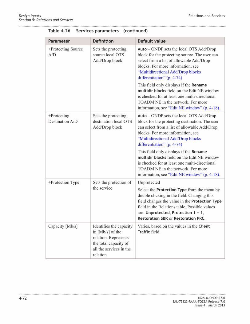
Table 4-26 Services parameters (continued)
Parameter Definition Default value
+Protecting Source
A/D
Sets the protecting
source local OTS
Add/Drop block
Auto – ONDP sets the local OTS Add/Drop
block for the protecting source. The user can
select from a list of allowable Add/Drop
blocks. For more information, see
“Multidirectional Add/Drop blocks
differentiation” (p. 4-74)
This field only displays if the Rename
multidir blocks field on the Edit NE window
is checked for at least one multi-directional
TOADM NE in the network. For more
information, see “Edit NE window” (p. 4-18).
+Protecting
Destination A/D
Sets the protecting
destination local OTS
Add/Drop block
Auto – ONDP sets the local OTS Add/Drop
block for the protecting destination. The user
can select from a list of allowable Add/Drop
blocks. For more information, see
“Multidirectional Add/Drop blocks
differentiation” (p. 4-74)
This field only displays if the Rename
multidir blocks field on the Edit NE window
is checked for at least one multi-directional
TOADM NE in the network. For more
information, see “Edit NE window” (p. 4-18).
+Protection Type Sets the protection of
the service
Unprotected
Select the Protection Type from the menu by
double clicking in the field. Changing this
field changes the value in the Protection Type
field in the Relations table. Possible values
are: Unprotected, Protection 1 + 1,
Restoration SBR or Restoration PRC.
Capacity [Mb/s] Identifies the capacity
in [Mb/s] of the
relation. Represents
the total capacity of
all the services in the
relation.
Varies, based on the values in the Client
Traffic field.
Design Inputs
Section 5: Relations and Services
Relations and Services
....................................................................................................................................................................................................................................
....................................................................................................................................................................................................................................
4-72 1626LM ONDP R7.0
3AL-75223-RAAA-TQZZA Release 7.0
Issue 4 March 2013

Table 4-26 Services parameters (continued)
Parameter Definition Default value
+Disjointness Sets disjoint
condition for diverse
path routing
Varies, based on the value selected in the
Protection Type field. Affects the routing of
the nominal and the protection path to have a
disjoint path only on link or on nodes and
links.
Mutual Disjointness Identifies the services
that are mutually
disjointed for the path
computation
Displays the label of the service specified on
the Set Mutual Disjointness window. For more
information, see “Set Mutual Disjointness
window” (p. 4-76).
Constraints Identifies the working
or protecting
constraints for the
spatial and/or spectral
paths.
Varies, base on the values set
Services table buttons
The Services table in the Edit Services window contains buttons which perform the
following actions.
Table 4-27 Services table button actions
Button Tool tip Description
Add a service with the specified
parameters to the relation. The tool tip
displays the parameters of the service
that will be added.
For more information on how to
change the parameter information
before adding the span, see “Change
Service Parameters and Copy to a
New Service” (p. 4-82).
Remove selected services Delete the highlighted services from
the relation.
Remove all services Delete all services from the relation.
Design Inputs
Section 5: Relations and Services
Relations and Services
....................................................................................................................................................................................................................................
....................................................................................................................................................................................................................................
1626LM ONDP R7.0
3AL-75223-RAAA-TQZZA Release 7.0
Issue 4 March 2013
4-73

Multidirectional Add/Drop blocks differentiation
The following fields in the Edit Services window facilitate the differentiation of the
multidirectional Add/Drop blocks in multidirectional configurations.
• Working Source A/D
• Working Destination A/D
• Protecting Source A/D
• Protecting Destination A/D
Note: These fields display only if the user assigns a specific name to each
multidirectional Add/Drop block of at least one multidirectional NE in the network. This
is done by checking the Rename multidir blocks field on the Edit NE window, and
entering a one character string in the Multidir blocks name field for each Add/Drop
block. For more information, see “Edit NE window” (p. 4-18).
For each service, for the corresponding NE, these A/D fields set the Add/Drop block
supporting the associated transponder. The default value of these fields is Auto, meaning
the input is automatically set by ONDP. In the following cases, manual selection is
allowed, to change the value from that which is automatically set. Only allowable
selections are presented, based on the type of NE. The following are possible allowed
values:
• Uni – the service Add/Drop is performed on the corresponding fixed Add/Drop block
• Multi_# – the service Add/Drop is performed on the selected named multidirectional
Add/Drop block. The # is the name set in the Multidir blocks names field, in the Edit
NE window.
If no protection is defined for the service, a dash (-) displays in the Protecting Source
A/D and Protecting Destination A/D fields. This is not modifiable.
Edit Spectral Constraint window
The Edit Spectral Constraint window is used to manually define the spectral constraints
on a service, once the spatial constraint is defined. A spectral constraint can be both on the
working or protecting path.
Using the Edit Spectral Constraint window, the user can do the following:
• Add or remove 3Rs
• Define color constraints
• Identify conflicts between constraints and. ALC channels
For more information, see “Edit Spatial and Spectral Constraints” (p. 4-86).
Design Inputs
Section 5: Relations and Services
Relations and Services
....................................................................................................................................................................................................................................
....................................................................................................................................................................................................................................
4-74 1626LM ONDP R7.0
3AL-75223-RAAA-TQZZA Release 7.0
Issue 4 March 2013

The following table describes the fields and options on the Edit Spectral Constraints
window.
Field/Option Description
Current Service: Identifies the name of the service and whether the
service is Working or Protecting
Slide Fields Slide left or right to decrease or increase the value.
Drop Select the Drop value from the list. Possible selections
are: Auto, Uni, or Multi_#
Add Select the Add value from the list. Possible selections
are: Auto, Uni, or Multi_#
Highlight on Map Highlights the service on the Topology Map
Figure 4-23 Edit Spectral Constraint window
Design Inputs
Section 5: Relations and Services
Relations and Services
....................................................................................................................................................................................................................................
....................................................................................................................................................................................................................................
1626LM ONDP R7.0
3AL-75223-RAAA-TQZZA Release 7.0
Issue 4 March 2013
4-75

Field/Option Description
Clear all 3Rs Remove all 3Rs from this service
Display “Frequency” Select from the pull-down list to change the displayed
information in the Edit Spectral Constraints window.
Possible selections are: Display “ITU Id”, Display
“Frequency”, or Display “Wavelength”.
Activate Single Color Check this box to have the same color on each trail.
Conflicts Count Indicates the number of constraints and/or ALC channel
conflicts
Set Mutual Disjointness window
The Set Mutual Disjointness window sets the services that are mutually disjointed for the
path computation.
Design Inputs
Section 5: Relations and Services
Relations and Services
....................................................................................................................................................................................................................................
....................................................................................................................................................................................................................................
4-76 1626LM ONDP R7.0
3AL-75223-RAAA-TQZZA Release 7.0
Issue 4 March 2013

Figure 4-24 Set Mutual Disjointness window
Design Inputs
Section 5: Relations and Services
Relations and Services
....................................................................................................................................................................................................................................
....................................................................................................................................................................................................................................
1626LM ONDP R7.0
3AL-75223-RAAA-TQZZA Release 7.0
Issue 4 March 2013
4-77

Create a Relation
When to use
Use this task to create a relation. When a relation is created between two sites, a default
service is automatically created. Additionally, you can access the Edit Services window
and manually add any services.
Related information
See the following topic in this document:
• “Relations and Services” (p. 4-57)
Before you begin
This task does not have any preconditions.
Task
Complete the following steps to create a relation.
...................................................................................................................................................................................................
1 Do one of the following:
• Select the Create Relation icon on the Topology Map toolbar.
• Right click the site to display the Site pop-up menu. From the Site pop-up menu,
select Create Relation.
...................................................................................................................................................................................................
2 On the Topology Map, click the Site from which the relation originates and drag the
cursor to the site on which the relation terminates.
Result: A red line representing a relation is created between the sites.
Note: To create services see the “Create Services” (p. 4-80) task.
Design Inputs
Section 5: Relations and Services
Create a Relation
....................................................................................................................................................................................................................................
....................................................................................................................................................................................................................................
4-78 1626LM ONDP R7.0
3AL-75223-RAAA-TQZZA Release 7.0
Issue 4 March 2013
E N D O F S T E P S...................................................................................................................................................................................................

Edit Relations and Services
When to use
Relations and Services are viewable and editable from the Edit Services window. Use this
task to view and edit relations and services.
Warning: Interaction occurs between the Relations table and the Services table. Changing
a parameter in one table can affect the parameters in the other. For example, if the
Services Count is changed in the Relations table, the services for the relation are
redefined in the Services table.
Related information
See the following topic in this document:
• “Relations and Services” (p. 4-57)
Before you begin
This task does not have any preconditions.
Task
Complete the following steps to view and edit relations and services.
...................................................................................................................................................................................................
1 Display the Edit Services window by doing one of the following:
• From the Topology Map Main menu, follow this path:
Inputs > Edit Relation/Services
• Right click a relation on the Topology Map. From the Relations pop-up window,
select Highlight in Table.
Result: The Edit Services window is displayed. Relations that are selected on the
Topology Map are highlighted in the table. For an illustration of the Edit Services
window, see “Edit Services window” (p. 4-57).
...................................................................................................................................................................................................
2 Edit the relations/services parameters. For a description of the relation parameters, see
Table 4-21, “Services table pop-up menu ” (p. 4-65). For a description of the services
parameters, see Table 4-26, “Services parameters” (p. 4-70).
Result: The relations and services are changed.
Design Inputs
Section 5: Relations and Services
Edit Relations and Services
....................................................................................................................................................................................................................................
....................................................................................................................................................................................................................................
1626LM ONDP R7.0
3AL-75223-RAAA-TQZZA Release 7.0
Issue 4 March 2013
4-79
E N D O F S T E P S...................................................................................................................................................................................................

Create Services
When to use
Use this task to create a relation. When a relation is created between two sites, a service is
not automatically created. To create services, access the Edit Services window and
manually add any services.
Related information
See the following topic in this document:
• “Relations and Services” (p. 4-57)
Before you begin
This task does not have any preconditions.
Task
Complete the following steps to create a relation.
...................................................................................................................................................................................................
1 Follow the steps in the “Create a Relation” (p. 4-78) task to create a relation.
...................................................................................................................................................................................................
2 Display the Edit Services window by doing one of the following:
• From the Topology Map Main menu, follow this path:
Inputs > Edit Relation/Services
• Right click a relation on the Topology Map. From the Relations pop-up window,
select Highlight in Table.
Result: The Edit Services window is displayed. Relations that are selected on the
Topology Map are highlighted in the table. For an illustration of the Edit Services
window, see “Edit Services window” (p. 4-57).
...................................................................................................................................................................................................
3 If not already done so, select a relation in the Relations table.
...................................................................................................................................................................................................
4 Do one of the following to add services to the selected relation.
• In the Relations table, click in the Services Count field and enter the number of
services.
• In the Services table, mouse over the Add Service button on the left side of the table.
If the Service parameters are correct, click the Add Service button.
Design Inputs
Section 5: Relations and Services
Create Services
....................................................................................................................................................................................................................................
....................................................................................................................................................................................................................................
4-80 1626LM ONDP R7.0
3AL-75223-RAAA-TQZZA Release 7.0
Issue 4 March 2013

Note: The Add Service button tool tip displays the parameters of the service that are
added. To change the parameters of a service and copy them to a new service, see
“Change Service Parameters and Copy to a New Service” (p. 4-82).
Result: Services are created for the relation and the associated parameters are
redefined in the tables.
Design Inputs
Section 5: Relations and Services
Create Services
....................................................................................................................................................................................................................................
....................................................................................................................................................................................................................................
1626LM ONDP R7.0
3AL-75223-RAAA-TQZZA Release 7.0
Issue 4 March 2013
4-81
E N D O F S T E P S...................................................................................................................................................................................................

Change Service Parameters and Copy to a New Service
When to use
Use this task to Change Service Parameters and Copy to a New Service.
Warning: Interaction occurs between the Relations table and the Services table. Changing
a parameter in one table can affect the parameters in the other.
Related information
See the following topic in this document:
• “Relations and Services” (p. 4-57)
Before you begin
This task does not have any preconditions.
Task
Complete the following steps to change the service information displayed in the Add
Service button tool tip and copy to a new service.
...................................................................................................................................................................................................
1 Follow the first step in the “Edit Relations and Services” (p. 4-79) to display the Edit
Services window.
Result: The Edit Services window is displayed.
...................................................................................................................................................................................................
2 Click the relation to which service will be added.
Result: The relation is selected and the services in the relation are displayed in the
Services table.
...................................................................................................................................................................................................
3 From the Services table, select the service to copy.
...................................................................................................................................................................................................
4 Do one of the following:
• To copy all the service parameters to the Add Service button tool tip, right click in the
table to display the Services table pop-up menu, and select Copy Service to Add
Model.
• To change a parameter in the service, edit the service parameter, right click in the
table to display the Services table pop-up menu, and select Copy Cell to Add Model.
Note: The Copy Cell to Add Model function is not available for the Client traffic,
Concentration, or OCH Line parameters.
Design Inputs
Section 5: Relations and Services
Change Service Parameters and Copy to a New Service
....................................................................................................................................................................................................................................
....................................................................................................................................................................................................................................
4-82 1626LM ONDP R7.0
3AL-75223-RAAA-TQZZA Release 7.0
Issue 4 March 2013

Result: The Service parameter information is changed in the Add Service button tool
tip. To view the change applied to the Add Model, mouse over the Add Service button
for at least one second.
...................................................................................................................................................................................................
5 Click the Add Service button.
Result: The new service is added to the table below the selected row.
Design Inputs
Section 5: Relations and Services
Change Service Parameters and Copy to a New Service
....................................................................................................................................................................................................................................
....................................................................................................................................................................................................................................
1626LM ONDP R7.0
3AL-75223-RAAA-TQZZA Release 7.0
Issue 4 March 2013
4-83
E N D O F S T E P S...................................................................................................................................................................................................

Delete Relations and Services
When to use
Use this task to delete relations and services from the network design.
Related information
See the following topic in this document:
• “Relations and Services” (p. 4-57)
Before you begin
This task does not have any preconditions.
Task
Complete the following steps to delete relations and services from the network design.
...................................................................................................................................................................................................
1 Do one of the following:
• Follow the first step in the “Edit Relations and Services” (p. 4-79) task to display the
Edit Services window and select the relations or services to be deleted. Do one of the
following:
– Click the Remove selected relations or the Remove selected services button.
– From the Relations table, select the Remove all relations button.
– From the Services table, select the Remove all services button.
• From the Topology Map, select the relations to be deleted. Do one of the following:
– Click the Delete Selected icon from the toolbar.
– From the Main menu, follow this path:
Edit > Delete Selected.
– Right click the Map and select Delete All Selected from the Map pop-up menu.
Result: The relations and services are deleted.
Design Inputs
Section 5: Relations and Services
Delete Relations and Services
....................................................................................................................................................................................................................................
....................................................................................................................................................................................................................................
4-84 1626LM ONDP R7.0
3AL-75223-RAAA-TQZZA Release 7.0
Issue 4 March 2013
E N D O F S T E P S...................................................................................................................................................................................................

Identify a Relation on the Map
When to use
Use this task to identify a relation on the Topology Map.
Related information
See the following topic in this document:
• “Relations and Services” (p. 4-57)
Before you begin
Before beginning this task, a relation must be created.
Task
Complete the following steps to identify relations on the Map.
...................................................................................................................................................................................................
1 Follow the first step in the “Edit Relations and Services” (p. 4-79) task to display the Edit
Services window.
Result: The Edit Services window is displayed.
...................................................................................................................................................................................................
2 Select a relation by clicking the relation row. Multiple relations can be selected by
holding the [Shift] key while selecting relations.
Result: The relations are selected.
...................................................................................................................................................................................................
3 Right click in the Edit Services window.
Result: The Relations pop-up window is displayed.
...................................................................................................................................................................................................
4 From the Relations pop-up window, select Highlight All Selected on Map.
Result: The selected relations are highlighted on the Topology Map.
Design Inputs
Section 5: Relations and Services
Identify a Relation on the Map
....................................................................................................................................................................................................................................
....................................................................................................................................................................................................................................
1626LM ONDP R7.0
3AL-75223-RAAA-TQZZA Release 7.0
Issue 4 March 2013
4-85
E N D O F S T E P S...................................................................................................................................................................................................

Edit Spatial and Spectral Constraints
When to use
Use this task to create or edit spectral constraints for working and protecting paths.
The use of spectral and spacial routing constraints enables the user to impact the Routing
and Wavelength Allocation (RWA) of services. It is possible to specify both the path
(spatial constraint) and the wavelength (spectral constraint). The spatial constraint must
be defined before the spectral constraint.
Related information
See the following topic in this document:
• “Relations and Services” (p. 4-57)
• “Edit Spectral Constraint window” (p. 4-74)
• “Edit Spatial and Spectral Constraints” (p. 4-86)
Before you begin
Before beginning this task, a relation must be created.
Task
Complete the following steps to create or edit spectral constraints for working and
protecting paths.
...................................................................................................................................................................................................
1 On the Topology Map, highlight the link associated with the relation/service for which the
spectral constraints will be set.
...................................................................................................................................................................................................
2 Open the Edit Services window using one of the following methods.
• Right click on the relation on the Topology Map, and select Highlight in Table from
the Relation pop-up menu
• From the Main menu, select Inputs > Edit Relations/Services. Select the relation
associated with the link selected in Step 1.
Result: The Edit Services window is displayed, and the relation is highlighted in the
Relations table.
...................................................................................................................................................................................................
3 From the Edit Services window, select the service(s) from the Services table.
Note: If a service is not selected, the constraints will be set for all services in the relation.
Design Inputs
Section 5: Relations and Services
Edit Spatial and Spectral Constraints
....................................................................................................................................................................................................................................
....................................................................................................................................................................................................................................
4-86 1626LM ONDP R7.0
3AL-75223-RAAA-TQZZA Release 7.0
Issue 4 March 2013

...................................................................................................................................................................................................
4 Right click in the Relations table or Services table to display the table pop-up menu.
...................................................................................................................................................................................................
5 From the table pop-up menu, select Working [W] Constraints... or Protecting [P]
Constraints....
Result: The Working [W] Constraints... or the Protecting [P] Constraints... pop-up
menu is displayed.
...................................................................................................................................................................................................
6 From the Working [W] Constraints... or Protecting [P] Constraints... pop-up menu, select
either Set [W] Path Constraints from Map Selection or Set [P] Path Constraints from
Map Selection.
Result: The Constraints field changes to W[Manu S] or P[Manu S].
...................................................................................................................................................................................................
7 Select the service(s) in the Service table for which the spectral constraints will be set.
Right click in the Services table to display the Services table pop-up menu.
...................................................................................................................................................................................................
8 From the Services table pop-up menu, select Edit Working [W] Constraints... or Edit
Protecting [P] Constraints.
Result: The Edit Spectral Constraints window is displayed.
...................................................................................................................................................................................................
9 Edit the spectral constraints for the working or protecting path.
Result: The constraint is set.
After running the design, the user can freeze the computed path in order to perform a new
design with the previously computed path as a constraint. To freeze the computed path
follow these steps:
• From the Services table, right click on the constraints to display the Service table
pop-up menu
• From the Services table pop-up menu, select Working [W] Constraints or Protecting
[P] Constraints to display the Working [W] Constraints or Protecting [P] Constraints
pop-up menu
• From the Working [W] Constraints pop-up menu or the Protecting [P] Constraints
pop-up menu, select either Freeze Computed Path (Spatial Only) or Freeze
Computed Path (Spatial + Spectral)
Design Inputs
Section 5: Relations and Services
Edit Spatial and Spectral Constraints
....................................................................................................................................................................................................................................
....................................................................................................................................................................................................................................
1626LM ONDP R7.0
3AL-75223-RAAA-TQZZA Release 7.0
Issue 4 March 2013
4-87
E N D O F S T E P S...................................................................................................................................................................................................

Section 6: Optical Subsets
Overview
Purpose
This section provides information on optical subsets.
Contents
Optical Subsets 4-89
Create Optical Subset 4-97
Design Inputs Overview
....................................................................................................................................................................................................................................
....................................................................................................................................................................................................................................
4-88 1626LM ONDP R7.0
3AL-75223-RAAA-TQZZA Release 7.0
Issue 4 March 2013

Optical Subsets
Optical Subset
An optional step in network planning and design is to consider grouping channels into
optical subsets. In ONDP, optical subsets allow the user to manage the following:
• Subset name
• Subset Channel Mask – channels not included are forbidden. Selection can be by
channel spacing mask or specific mask
• Maximum number of channel supported by the subset
• Allowed line bitrate and encoding
• Line tuning preference
For information on how to perform tasks related to optical subsets, see:
• “Create Optical Subset” (p. 4-97)
Edit Optical Subsets window
The Edit Optical Subsets window is used to configure parameters of the Optical Subset.
To access the Edit Optical Subsets window, follow this menu path: Inputs > Edit Optical
Subsets
Optical Subset parameters
Editable Optical Subset parameters are indicated by a plus sign (+) appearing before the
parameter title. These parameters can be edited by double clicking the field and entering
the value in the Edit Optical Subsets window. To change a field, press the Tab key or click
in a different field.
Figure 4-25 Edit Optical Subsets window
Design Inputs
Section 6: Optical Subsets
Optical Subsets
....................................................................................................................................................................................................................................
....................................................................................................................................................................................................................................
1626LM ONDP R7.0
3AL-75223-RAAA-TQZZA Release 7.0
Issue 4 March 2013
4-89

Warning: Interaction occurs between the Links window, as well as other affected
windows and reports throughout the tool. For example, if the Name field is changed on
the Edit Optical Subset window, the Subset name will change in the Edit Spans window,
and reports in which Subset name is contained.
Table 4-28 Optical Subset parameters
Parameter Definition Default value
+Name Name to identify the
subset
System generated. Editable field. Any string of
characters allowed.
+Channel Mask Sets the channel mask
of the subset by
channel spacing or
specific mask.
Channels not selected
are excluded from the
subset.
Possible values are:
• Global – (default) – all channels are
included in the subset
• 50 GHz
• 100 GHz
• 200 GHz
• DSF mask: 16 fixed ch
• DSF masks: 2 Forghieri grids
For more information, see “Channel Mask
parameter” (p. 4-92).
Channel Max
Number
Maximum number of
channels supported
by the subset links.
Auto. Controlled globally on the Set Design
Parameters window. User is able to edit this
field. For more information see, “Channel max
number parameter” (p. 4-93)
+Allowed Bitrate and
Encoding
The bitrate and
encoding allowed for
this subset.
Auto. Controlled globally on the Set Design
Parameters window. The user is able to edit
this field by selecting from the allowed values
in the list. For more information, see
“Transponder bitrate & encoding” (p. 4-118).
+Line Tuning Pref. The line tuning
optimization
preference for this
subset
APE. If line tuning preference is applicable to a
link, the specified line tuning is used. This is
typically used for a fixed terminal - fixed
terminal configuration. Line tuning preference
is applicable to a link when it is possible to
make a design based on APE or on APA.
Note: APA design is not guaranteed.
Edit Optical Subsets pop-up menu
The Edit Optical Subsets window contains a pop-up menu that offers additional actions to
configure subsets. To access the Edit Optical Subsets pop-up menu, right click any field
in the table.
Design Inputs
Section 6: Optical Subsets
Optical Subsets
....................................................................................................................................................................................................................................
....................................................................................................................................................................................................................................
4-90 1626LM ONDP R7.0
3AL-75223-RAAA-TQZZA Release 7.0
Issue 4 March 2013

The following table describes the options in the Edit Optical Subsets window pop-up
menu.
Table 4-29 Edit Optical Subsets pop-up menu
Option Description
Undo Undo the last action
Redo Redo the last action
Copy Selected Cells Copy selected cells to the clip board
Paste Cells Paste the copied cells at the cursor insertion point
Select All Select all links on the map
Deselect All Clear all previously selected links.
Edit Selected Subset Mask Open the Edit Subset Mask window to change the
properties of the selected subset mask. For more
information, see “Edit Subset Mask window” (p. 4-95).
Highlight All Selected on Map Highlight on the Topology Map, the subsets that are
selected in the Edit Optical Subsets window
Figure 4-26 Edit Optical Subsets window pop-up menu
Design Inputs
Section 6: Optical Subsets
Optical Subsets
....................................................................................................................................................................................................................................
....................................................................................................................................................................................................................................
1626LM ONDP R7.0
3AL-75223-RAAA-TQZZA Release 7.0
Issue 4 March 2013
4-91
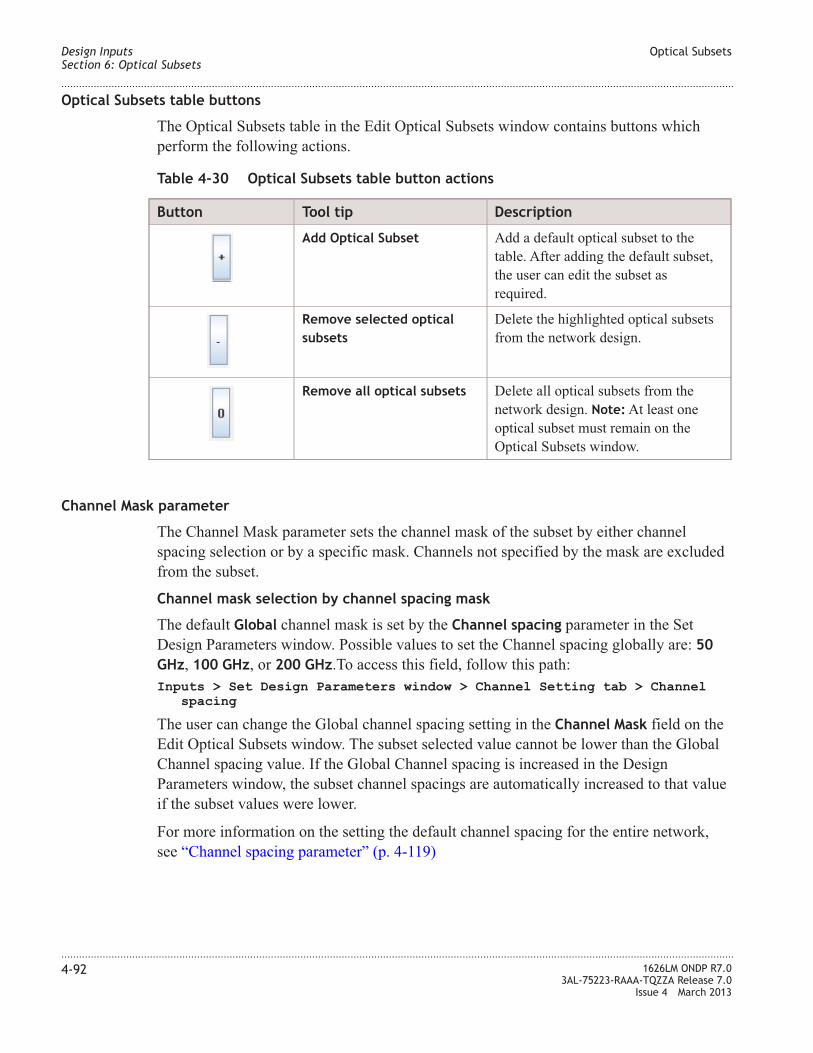
Optical Subsets table buttons
The Optical Subsets table in the Edit Optical Subsets window contains buttons which
perform the following actions.
Table 4-30 Optical Subsets table button actions
Button Tool tip Description
Add Optical Subset Add a default optical subset to the
table. After adding the default subset,
the user can edit the subset as
required.
Remove selected optical
subsets
Delete the highlighted optical subsets
from the network design.
Remove all optical subsets Delete all optical subsets from the
network design. Note: At least one
optical subset must remain on the
Optical Subsets window.
Channel Mask parameter
The Channel Mask parameter sets the channel mask of the subset by either channel
spacing selection or by a specific mask. Channels not specified by the mask are excluded
from the subset.
Channel mask selection by channel spacing mask
The default Global channel mask is set by the Channel spacing parameter in the Set
Design Parameters window. Possible values to set the Channel spacing globally are: 50
GHz, 100 GHz, or 200 GHz.To access this field, follow this path:
Inputs > Set Design Parameters window > Channel Setting tab > Channel
spacing
The user can change the Global channel spacing setting in the Channel Mask field on the
Edit Optical Subsets window. The subset selected value cannot be lower than the Global
Channel spacing value. If the Global Channel spacing is increased in the Design
Parameters window, the subset channel spacings are automatically increased to that value
if the subset values were lower.
For more information on the setting the default channel spacing for the entire network,
see “Channel spacing parameter” (p. 4-119)
Design Inputs
Section 6: Optical Subsets
Optical Subsets
....................................................................................................................................................................................................................................
....................................................................................................................................................................................................................................
4-92 1626LM ONDP R7.0
3AL-75223-RAAA-TQZZA Release 7.0
Issue 4 March 2013

Channel mask selection by specific mask
Specific subset masks can also be set for network designs that include G653 Dispersion
Shifted Fiber (DSF), which carries irregular channel spacing. Two subset mask settings
are supported:
• DSF mask: 16 fixed chs – for more information, see “DSF mask: 16 fixed channels”
(p. 4-93)
• DSF mask: 2 Foghieri grids – For more information, see “DSF Mask: 2 Forghieri
grids” (p. 4-94)
Channel max number parameter
The Channel max number parameter allows the user to set the maximum number of
channels supported by links in the specified subset. This parameter is set globally in the
Transponder bitrate and encoding parameter on the Set Design Parameters window.
The default of Auto in this field indicates the value is the same as the global parameter.
The user is able to edit this field. Possible values are 1 to 96, except where limited by the
architecture. For more information, see “Transponder bitrate & encoding” (p. 4-118).
Channel Allocations for G653 DSF
The following sections describe the channel allocations for the selected Channel Mask if
G653 DSF is in the subset.
50GHz, 100 GHz, and 200 GHz channel spacing
For network designs containing G653 DSF that choose 50GHz, 100 GHz, and 200 GHz
channel spacing for the Channel Mask, channel allocation to Band 5 is forbidden.
Therefore the following channels number of channels are available for the OMS:
• Channels loaded at 50 GHz – only 88 channels are available for the OMS if DSF is in
the OMS
• Channels loaded at 100 GHz – only 44 channels are available for the OMS if DSF is
in the OMS
• Channels loaded at 200 GHz – only 22 channels are available for the OMS if DSF is
in the OMS
DSF mask: 16 fixed channels
The following table lists the channel allocation for network designs containing G653 DSF
that specify a G653 DSF fixed grid of 16 channels for the Channel Mask,
Channel Frequency (THz) Wavelength (nm)
16 195.850 1530.73
15 195.700 1531.89
14 195.450 1533.86
Design Inputs
Section 6: Optical Subsets
Optical Subsets
....................................................................................................................................................................................................................................
....................................................................................................................................................................................................................................
1626LM ONDP R7.0
3AL-75223-RAAA-TQZZA Release 7.0
Issue 4 March 2013
4-93

Channel Frequency (THz) Wavelength (nm)
13 195.250 1535.43
12 194.900 1538.19
11 194.600 1540.56
10 194.450 1541.75
9 193.700 1547.72
8 193.300 1550.92
7 193.100 1552.52
6 192.750 1555.34
5 192.450 1557.77
4 192.300 1558.98
3 192.050 1561.01
2 191.850 1562.64
1 191.600 1564.68
DSF Mask: 2 Forghieri grids
The Channel Mask DSF Mask: 2 Forghieri grids allows ONDP to provide a Channel
Mask based on a Forghieri grid with 8 channels with irregular channel spacing.
The typical Forghieri grid uses a 1–3–2 format where:
• Based on the specified first frequency (Example: v1 = 193.90 THz)
• The 2nd frequency is 100 GHz from the 1st (Example: v2 = 193.80THz)
• The 3rd frequency is 300 GHz from the 2nd (Example: v3 = 193.50 THz)
• The 4th frequency is 200 GHz from the 3rd (Example: v4 = 193.30 THz)
ONDP supports 2 Forghieri grids, therefore 2 first frequencies are specified for this mask.
For information on how to modify these channel mask frequency values, see “Edit Subset
Mask window” (p. 4-95). The default frequencies the ONDP provides for the DSF Mask:
2 Foghieri grids channel mask are:
• Grid 1 – 193.90 THz.
• Grid 2 – 192.00 THz
The user can modify the default first frequencies, however the 2 Forghieri grids must be
separated by at lease 10 nm. Additionally, if one of the 8 channels is in Band 5, an error
message is given, and the user is directed to choose another frequency for the mask.
Design Inputs
Section 6: Optical Subsets
Optical Subsets
....................................................................................................................................................................................................................................
....................................................................................................................................................................................................................................
4-94 1626LM ONDP R7.0
3AL-75223-RAAA-TQZZA Release 7.0
Issue 4 March 2013

Edit Subset Mask window
The Edit Subset Mask window allows the user to manage the Channel Mask properties of
the specified subset. To access this window, select a subset on the Edit Optical Subsets
window, and right click to display the Edit Optical Subsets pop-up menu. From the menu,
select Edit Selected Subset Mask.
The following table describes the fields and options on the Edit Subset Mask window
Field/Option Description
Edit Subset Name Identifies the name of the subset mask and
allows the user to edit the subset mask name.
Figure 4-27 Edit Subset Mask window
Design Inputs
Section 6: Optical Subsets
Optical Subsets
....................................................................................................................................................................................................................................
....................................................................................................................................................................................................................................
1626LM ONDP R7.0
3AL-75223-RAAA-TQZZA Release 7.0
Issue 4 March 2013
4-95

Field/Option Description
Select Mask Type Identifies the subset mask type and allows the
user to change the type of subset mask
Possible values are:
• Global – (default) – all channels are
included in the subset
• 50 GHz
• 100 GHz
• 200 GHz
• DSF mask: 16 fixed chs
• DSF masks: 2 Forghieri grids
For more information, see “Channel Mask
parameter” (p. 4-92).
Edit Forghieri Grid 1 Frequency Enter the starting frequency for the 1st
Forghieri Grid in GHz, or use the slide to
select it. The computed irregular channel
frequencies based on the 1–3–2 Forghieri Grid
spacing are listed below the field. For more
information, see “DSF Mask: 2 Forghieri
grids” (p. 4-94)
Edit Forghieri Grid 2 Frequency Enter the starting frequency for the 2nd
Forghieri Grid in GHz, or use the slide to
select it. The computed irregular channel
frequencies based on the 1–3–2 Forghieri Grid
spacing are listed below the field. For more
information, see “DSF Mask: 2 Forghieri
grids” (p. 4-94)
Design Inputs
Section 6: Optical Subsets
Optical Subsets
....................................................................................................................................................................................................................................
....................................................................................................................................................................................................................................
4-96 1626LM ONDP R7.0
3AL-75223-RAAA-TQZZA Release 7.0
Issue 4 March 2013

Create Optical Subset
When to use
Use this task to create an optical subset. By default, all channels are included in the subset
provided by ONDP named subset_1.
Related information
See the following topic in this document:
• “Optical Subsets” (p. 4-89)
Before you begin
This task does not have any preconditions.
Task
Complete the following steps to create an optical subset.
...................................................................................................................................................................................................
1 From the Topology Map Main menu, follow this path: Inputs > Edit Optical Subsets.
Result: The Edit Optical Subsets window is displayed.
...................................................................................................................................................................................................
2 From the Edit Optical Subsets window, click the Add Optical Subset button.
Result: A default optical subset is added to the table. Edit the newly created subset as
required.
Design Inputs
Section 6: Optical Subsets
Create Optical Subset
....................................................................................................................................................................................................................................
....................................................................................................................................................................................................................................
1626LM ONDP R7.0
3AL-75223-RAAA-TQZZA Release 7.0
Issue 4 March 2013
4-97
E N D O F S T E P S...................................................................................................................................................................................................

Section 7: Shared Risk Groups (SRGs) and Failure
Scope
Overview
Purpose
This section provides information on how to create, view, and edit Shared Risk Groups
(SRGs) and Failure Scope.
Contents
Shared Risk Groups (SRGs) 4-99
Failures Scope 4-105
Create an SRG 4-109
Include/Exclude Links/Sites in SRGs 4-110
Delete SRGs 4-111
Edit a Failures Scope 4-112
Design Inputs
Section 7: Shared Risk Groups (SRGs) and Failure Scope
Overview
....................................................................................................................................................................................................................................
....................................................................................................................................................................................................................................
4-98 1626LM ONDP R7.0
3AL-75223-RAAA-TQZZA Release 7.0
Issue 4 March 2013

Shared Risk Groups (SRGs)
Shared Risk Groups (SRGs)
An additional step in network planning and design is to consider the Shared Risk Groups.
A Shared Risk Group is a set of networking resources that experience the same risk of
being affected by a failure, such as a cable cut. A common risk exists for the elements of
the group. SRGs permit protection of traffic on a spare route which is different from the
main route, avoiding the risk of the same problem affecting all resources in the group. For
example, if an SRG consists of Link 1 and Link 2, a failure on the SRG affects both links.
Therefore, the working and protecting path must not use both links to protect from failure
of both links at the same time.
For information on how to perform tasks related to SRGs, see the following:
• “Create an SRG” (p. 4-109)
• “Include/Exclude Links/Sites in SRGs” (p. 4-110)
• “Delete SRGs” (p. 4-111)
Edit SRGs window
The Edit SRGs window is used to configure SRGs. The window contains two tabs:
Contents and Parameters.
Design Inputs
Section 7: Shared Risk Groups (SRGs) and Failure Scope
Shared Risk Groups (SRGs)
....................................................................................................................................................................................................................................
....................................................................................................................................................................................................................................
1626LM ONDP R7.0
3AL-75223-RAAA-TQZZA Release 7.0
Issue 4 March 2013
4-99

Figure 4-28 Edit SRGs window Contents tab
Design Inputs
Section 7: Shared Risk Groups (SRGs) and Failure Scope
Shared Risk Groups (SRGs)
....................................................................................................................................................................................................................................
....................................................................................................................................................................................................................................
4-100 1626LM ONDP R7.0
3AL-75223-RAAA-TQZZA Release 7.0
Issue 4 March 2013

Edit SRGs window Main menu
The Edit SRGs window Main menu contains the following options:
• SRG
• Included
• Excluded
Figure 4-29 Edit SRGs window Parameters tab
Design Inputs
Section 7: Shared Risk Groups (SRGs) and Failure Scope
Shared Risk Groups (SRGs)
....................................................................................................................................................................................................................................
....................................................................................................................................................................................................................................
1626LM ONDP R7.0
3AL-75223-RAAA-TQZZA Release 7.0
Issue 4 March 2013
4-101

SRG menu
SRG menu command Description
Create New Create a new SRG
Delete Selected Delete a selected SRG
Delete All SRGs Delete All SRGs from the network design
Included menu
Links/Sites can be included in SRGs using the Included commands.
Table 4-31 Included menu
Included menu commands Description
Select All Select all Links/Sites in the Included list of the
Edit SRG window
Select None Clear any link in the Included list of the Edit
SRG window
Highlight All On Map Highlight all Links/Sites in the Included list of
the Edit SRG window on the Topology Map
Figure 4-30 SRG menu
Figure 4-31 Included menu
Design Inputs
Section 7: Shared Risk Groups (SRGs) and Failure Scope
Shared Risk Groups (SRGs)
....................................................................................................................................................................................................................................
....................................................................................................................................................................................................................................
4-102 1626LM ONDP R7.0
3AL-75223-RAAA-TQZZA Release 7.0
Issue 4 March 2013

Table 4-31 Included menu (continued)
Included menu commands Description
Highlight Selected On Map Highlight on the Topology Map only the
Links/Sites selected in the Included list of the
Edit SRG window
Set From Map Selection Include the Links/Sites selected on the
Topology Map in the SRG. Links/Sites that are
not selected on the Topology Map are moved
to the Excluded list
Transfer Map Selection Highlight in the Included list of the Edit SRG
window the Links/Sites selected on the
Topology Map
Excluded Menu
Links/Sites can be excluded from SRGs using the Excluded menu commands.
Table 4-32 Excluded menu
Excluded menu commands Description
Select All Select all Links/Sites in the Excluded list of
the Edit SRG window
Select None Clear any Links/Sites in the Excluded list of
the Edit SRG window
Highlight All On Map Highlight all Links/Sites in the Excluded list
of the Edit SRG window on the Topology Map
Highlight Selected On Map Highlight on the Topology Map only the
Links/Sites selected in the Excluded list of the
Edit SRG window
Figure 4-32 Excluded menu
Design Inputs
Section 7: Shared Risk Groups (SRGs) and Failure Scope
Shared Risk Groups (SRGs)
....................................................................................................................................................................................................................................
....................................................................................................................................................................................................................................
1626LM ONDP R7.0
3AL-75223-RAAA-TQZZA Release 7.0
Issue 4 March 2013
4-103

Table 4-32 Excluded menu (continued)
Excluded menu commands Description
Set From Map Selection Exclude the Links/Sites selected on the
Topology Map in the SRG. Links/Sites that are
not selected on the Topology Map are moved
to the Included list.
Transfer Map Selection Highlight in the Excluded list of the Edit SRG
window the Links/Sites selected on the
Topology Map
Transfer buttons
On the Edit SRG window, Links/Sites are moved between the Included list and the
Excluded list by selecting Links/Sites in either list and clicking a Transfer button.
Links/Sites that have been moved from one list are highlighted in the list to which they
have been moved.
Figure 4-33 Transfer buttons
Design Inputs
Section 7: Shared Risk Groups (SRGs) and Failure Scope
Shared Risk Groups (SRGs)
....................................................................................................................................................................................................................................
....................................................................................................................................................................................................................................
4-104 1626LM ONDP R7.0
3AL-75223-RAAA-TQZZA Release 7.0
Issue 4 March 2013

Failures Scope
Failures Scope
An additional step in network planning and design is to consider the Failures Scope.
The Failures Scope defines the elements that will fail when performing a failure analysis.
By default, all line links (OMS) and all SRGs are included in the failure scope, and all
multirect Add/Drop blocks and all sites (nodes) are excluded in the failure scope. Failures
Scope allows the user to choose the set of resources (links, nodes, and SRGs) that will
fail. This feature enables the user to refine the failure analysis, study specific scenarios or
reduce the time of the simulation.
For information on how to perform tasks related to Failures Scope, see the following:
• “Edit a Failures Scope” (p. 4-112)
Edit Failures Scope window
The Edit Failures Scope window is used to define manually the scope of the failure.
Design Inputs
Section 7: Shared Risk Groups (SRGs) and Failure Scope
Failures Scope
....................................................................................................................................................................................................................................
....................................................................................................................................................................................................................................
1626LM ONDP R7.0
3AL-75223-RAAA-TQZZA Release 7.0
Issue 4 March 2013
4-105

Edit Failures Scope window menu
The Edit Failures Scope window contains the following options:
• Included
• Excluded
Included menu
Links, SRGs, and Sites can be included in the failure scope using the Included menu
commands.
Table 4-33 Included menu
Included menu commands Description
Select All Select all resources in the Included list of the
Edit Failures Scope window
Select None Clear any resource in the Included list of the
Edit Failures Scope window
Highlight All On Map Highlight all resources in the Included list of
the Edit Failures Scope window on the
Topology Map
Highlight Selected On Map Highlight on the Topology Map only the
resources selected in the Included list of the
Edit Failures Scope window
Set From Map Selection Include the resources selected on the Topology
Map in the failure scope. Resources that are
not selected on the Topology Map are moved
to the Excluded list.
Transfer Map Selection Highlight in the Included list of the Edit
Failures Scope window the resources selected
on the Topology Map
Figure 4-34 Included menu
Design Inputs
Section 7: Shared Risk Groups (SRGs) and Failure Scope
Failures Scope
....................................................................................................................................................................................................................................
....................................................................................................................................................................................................................................
4-106 1626LM ONDP R7.0
3AL-75223-RAAA-TQZZA Release 7.0
Issue 4 March 2013
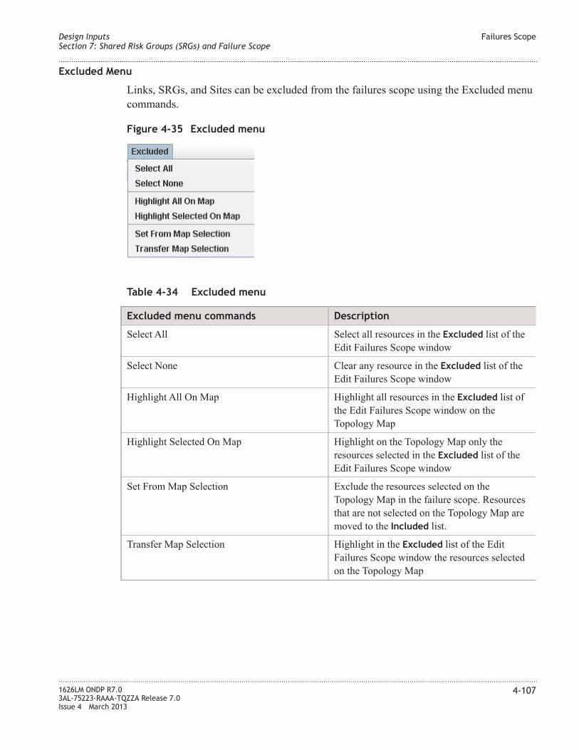
Excluded Menu
Links, SRGs, and Sites can be excluded from the failures scope using the Excluded menu
commands.
Table 4-34 Excluded menu
Excluded menu commands Description
Select All Select all resources in the Excluded list of the
Edit Failures Scope window
Select None Clear any resource in the Excluded list of the
Edit Failures Scope window
Highlight All On Map Highlight all resources in the Excluded list of
the Edit Failures Scope window on the
Topology Map
Highlight Selected On Map Highlight on the Topology Map only the
resources selected in the Excluded list of the
Edit Failures Scope window
Set From Map Selection Exclude the resources selected on the
Topology Map in the failure scope. Resources
that are not selected on the Topology Map are
moved to the Included list.
Transfer Map Selection Highlight in the Excluded list of the Edit
Failures Scope window the resources selected
on the Topology Map
Figure 4-35 Excluded menu
Design Inputs
Section 7: Shared Risk Groups (SRGs) and Failure Scope
Failures Scope
....................................................................................................................................................................................................................................
....................................................................................................................................................................................................................................
1626LM ONDP R7.0
3AL-75223-RAAA-TQZZA Release 7.0
Issue 4 March 2013
4-107

Transfer buttons
On the Edit Failures Scope window, resources are moved between the Included list and
the Excluded list by selecting resources in either list and clicking a Transfer button.
Resources that have been moved from one list are highlighted in the list to which they
have been moved.
Figure 4-36 Transfer buttons
Design Inputs
Section 7: Shared Risk Groups (SRGs) and Failure Scope
Failures Scope
....................................................................................................................................................................................................................................
....................................................................................................................................................................................................................................
4-108 1626LM ONDP R7.0
3AL-75223-RAAA-TQZZA Release 7.0
Issue 4 March 2013

Create an SRG
When to use
Use this task to create an SRG.
Related information
See the following topic in this document:
• “Shared Risk Groups (SRGs)” (p. 4-99)
Before you begin
This task does not have any preconditions.
Task
Complete the following steps to create an SRG.
...................................................................................................................................................................................................
1 From the Topology Map Main menu, follow this path: Inputs > Edit SRGs.
Result: The Edit SRGs window is displayed.
...................................................................................................................................................................................................
2 From the Edit SRGs window Main menu, follow this path: SRG > Create New.
Result: The Parameters tab of the Edit SRGs window is displayed.
...................................................................................................................................................................................................
3 Enter the name of the SRG in the Label field and click Apply.
Result: The SRG is created. As the default, no Links/Sites are included in the SRG.
To include or exclude Links/Sites in the SRG, see “Include/Exclude Links/Sites in
SRGs” (p. 4-110).
Design Inputs
Section 7: Shared Risk Groups (SRGs) and Failure Scope
Create an SRG
....................................................................................................................................................................................................................................
....................................................................................................................................................................................................................................
1626LM ONDP R7.0
3AL-75223-RAAA-TQZZA Release 7.0
Issue 4 March 2013
4-109
E N D O F S T E P S...................................................................................................................................................................................................

Include/Exclude Links/Sites in SRGs
When to use
Use this task to include and exclude Links/Sites in an SRG.
Related information
See the following topic in this document:
• “Shared Risk Groups (SRGs)” (p. 4-99)
Before you begin
Before beginning this task the SRG must be created. Follow the steps in the “Create an
SRG” (p. 4-109) task to create an SRG.
Task
Complete the following steps to include and exclude Links/Sites in an SRG.
...................................................................................................................................................................................................
1 Select an SRG from the list of SRGs in the Edit SRGs window.
Result: The Included and Excluded Links/Sites for the selected SRG are displayed in
the Contents tab of the Edit SRGs window.
...................................................................................................................................................................................................
2 Use any of the following methods in combination or alone to include or exclude
Links/Sites in an SRG.
• Select Links/Sites in either the Included or Excluded column and move as desired
between the columns using the direction arrows.
• Select Links/Sites on the Topology map and then select the Set from Map Selection
item in either the Included menu or Excluded menu in the Edit SRG Main menu.
Design Inputs
Section 7: Shared Risk Groups (SRGs) and Failure Scope
Include/Exclude Links/Sites in SRGs
....................................................................................................................................................................................................................................
....................................................................................................................................................................................................................................
4-110 1626LM ONDP R7.0
3AL-75223-RAAA-TQZZA Release 7.0
Issue 4 March 2013
E N D O F S T E P S...................................................................................................................................................................................................

Delete SRGs
When to use
Use this task to delete an SRG.
Related information
See the following topic in this document:
• “Shared Risk Groups (SRGs)” (p. 4-99)
Before you begin
Before beginning this task the SRG must be created. Follow the steps in the “Create an
SRG” (p. 4-109) task to create an SRG.
Task
Complete the following steps to delete an SRG.
...................................................................................................................................................................................................
1 Select an SRG from the list of SRGs in the Edit SRGs window.
Result: The Included and Excluded Links/Sites for the selected SRG are displayed in
the Contents tab of the Edit SRGs window.
...................................................................................................................................................................................................
2 From the Main menu, select SRG > Delete Selected.
Result: The selected SRG is deleted. Note: To delete all SRGs, select SRG > Delete
All SRGs.
Design Inputs
Section 7: Shared Risk Groups (SRGs) and Failure Scope
Delete SRGs
....................................................................................................................................................................................................................................
....................................................................................................................................................................................................................................
1626LM ONDP R7.0
3AL-75223-RAAA-TQZZA Release 7.0
Issue 4 March 2013
4-111
E N D O F S T E P S...................................................................................................................................................................................................

Edit a Failures Scope
When to use
Use this task to edit the Failures Scope.
Related information
See the following topic in this document:
• “Failures Scope” (p. 4-105)
Before you begin
This task does not have any preconditions.
Task
Complete the following steps to include and exclude resources in the Failures Scope.
...................................................................................................................................................................................................
1 From the Topology map Main menu, select the Inputs menu.
Result: The Inputs menu is displayed.
...................................................................................................................................................................................................
2 Do one of the following:
• If the checkbox in the Automatic Failure Scope command is checked, click the
checkbox to unselect.
• If the checkbox in the Automatic Failure Scope command is not checked, select Edit
Failure Scope.
Result: The Edit Failures Scope window is displayed.
...................................................................................................................................................................................................
3 Use any of the following methods in combination or alone to include or exclude resources
in the Failures Scope.
• Select resources in either the Included or Excluded column and move as desired
between the columns using the direction arrows.
• Select resources on the Topology map and select the Set from Map Selection item in
either the Included menu or Excluded menu in the Edit Failures scope Main menu.
Result: The Included and Excluded resources are displayed in the Included or
Excluded column of the Edit Failures Scope window.
...................................................................................................................................................................................................
4 Click Apply.
Design Inputs
Section 7: Shared Risk Groups (SRGs) and Failure Scope
Edit a Failures Scope
....................................................................................................................................................................................................................................
....................................................................................................................................................................................................................................
4-112 1626LM ONDP R7.0
3AL-75223-RAAA-TQZZA Release 7.0
Issue 4 March 2013

Result: The Failures Scope is saved and the Edit Failures Scope window is closed.
Design Inputs
Section 7: Shared Risk Groups (SRGs) and Failure Scope
Edit a Failures Scope
....................................................................................................................................................................................................................................
....................................................................................................................................................................................................................................
1626LM ONDP R7.0
3AL-75223-RAAA-TQZZA Release 7.0
Issue 4 March 2013
4-113
E N D O F S T E P S...................................................................................................................................................................................................

Section 8: Design Parameters
Overview
Purpose
This section provides information on how to create, view, and edit design parameters.
Contents
Design Parameters 4-115
WDM Layer Design Parameters 4-117
Traffic Setting Design Parameters 4-122
Set Design Parameters 4-125
Design Inputs
Section 8: Design Parameters
Overview
....................................................................................................................................................................................................................................
....................................................................................................................................................................................................................................
4-114 1626LM ONDP R7.0
3AL-75223-RAAA-TQZZA Release 7.0
Issue 4 March 2013

Design Parameters
Design Parameters
The next step in network planning and design is to consider the design parameters.
Set Design Parameters window
The Set Design Parameters panel is used to configure the WDM layer options and
optimization settings details. The window is divided into tabs which facilitate the design
configuration.
To access the Design Parameters panel follow this path from the Main menu:
Inputs > Set Design Parameters
Design Inputs
Section 8: Design Parameters
Design Parameters
....................................................................................................................................................................................................................................
....................................................................................................................................................................................................................................
1626LM ONDP R7.0
3AL-75223-RAAA-TQZZA Release 7.0
Issue 4 March 2013
4-115

Figure 4-37 Set Design Parameters window
Design Inputs
Section 8: Design Parameters
Design Parameters
....................................................................................................................................................................................................................................
....................................................................................................................................................................................................................................
4-116 1626LM ONDP R7.0
3AL-75223-RAAA-TQZZA Release 7.0
Issue 4 March 2013

WDM Layer Design Parameters
WDM Layer tab
The WDM Layer tab contains configuration options for the WDM layer.
Figure 4-38 WDM Layer tab
Design Inputs
Section 8: Design Parameters
WDM Layer Design Parameters
....................................................................................................................................................................................................................................
....................................................................................................................................................................................................................................
1626LM ONDP R7.0
3AL-75223-RAAA-TQZZA Release 7.0
Issue 4 March 2013
4-117

Channel Properties parameters
The following sections describe the WDM layer Channel Properties.
Transponder bitrate & encoding
The Transponder bitrate & encoding field defines the size of the channel/trail that is set
on the WDM layer for TrxA and TrxB. Possible values are:
• OCH10G~NRZ
• OCH10G~NRZ~MLSE
• OCH40G~PDPSK
• OCH40G~PDPSK~PMDC
• OCH40G~PDPSK~EFEC
• OCH40G~PDPSK~EFEC~PMDC
• OCH40G~COHERENT
• OCH100G~NRZ~PDMQPSK~EFEC
• OCH100G~NRZ~XR~PDMQPSK~EFEC
Note 1: For mixed formats 40G~PDPSK~XXXX/10G, it is recommended that the
40G~PDPSK~XXXX equipment is specified in the TrxA field.
Note 2:For mixed formats between either a OCH40G~COHERENT,
OCH100G~NRZ~PDMQPSK~EFEC, or OCH100G~NRZ~XR~PDMQPSK~EFEC and a
non-coherent format, OCH40G~COHERENT, OCH100G~NRZ~PDMQPSK~EFEC, or
OCH100G~NRZ~XR~PDMQPSK~EFEC must be specified in the TrxA field.
Note 3: If Free DCU is specified in the Dispersion Compensation field, only
OCH40G~COHERENT, OCH100G~NRZ~PDMQPSK~EFEC, and
OCH100G~NRZ~XR~PDMQPSK~EFEC formats are allowed in the TrxA and TrxB fields.
The field next to the TrxA and TrxB fields contains the maximum capacity per fiber for
the specified granularity. The default value is 80. Possible values are 1 - 96. This value
corresponds to the maximum number of wavelengths that a link could have.
The 10G TRB field defines the type of 10 G transponder for the entire network. Possible
values are TR2D1191 or TRBD1191.
Dispersion Compensation
The Dispersion Compensation field determines the Dispersion Compensation Module
(DCM) option that is used for spans.
• Mix DCF & DC FBG for long span – for long spans Fiber Bragg Grating (FBG) is
used. For spans that are not long, Dispersion Compensation Fiber (DCF) is used. The
Mix DCF & DC FBG for long span option is the default.
• Full FBG – for applications in which spans are not long, DCF modules are replaced by
FBG modules to improve optical performance. In this case, all DCM are FBG.
Design Inputs
Section 8: Design Parameters
WDM Layer Design Parameters
....................................................................................................................................................................................................................................
....................................................................................................................................................................................................................................
4-118 1626LM ONDP R7.0
3AL-75223-RAAA-TQZZA Release 7.0
Issue 4 March 2013

• Full DCF (no FBG) – for applications in which spans are long, all FBG modules are
replaced by DCF modules. In this case, all DCM are DCF.
• Free DCU – for applications using 40 G coherent granularity only. No FBG modules
or DCM modules.
Dispersion Compensation parameter
The Dispersion Compensation field determines the Dispersion Compensation Module
(DCM) option that is used for spans.
• Mix DCF & DC FBG for long span – for long spans Fiber Bragg Grating (FBG) is
used. For spans that are not long, Dispersion Compensation Fiber (DCF) is used.
• Full FBG – for applications in which spans are not long, DCF modules are replaced by
FBG modules to improve optical performance. In this case, all DCM are FBG.
• Full DCF (no FBG) – for applications in which spans are long, all FBG modules are
replaced by DCF modules. In this case, all DCM are DCF.
• Free DCU – allowed only for applications using xx G coherent granularity only. No
FBG modules or DCM modules. This is the default value if only xxG coherent
formats are present in the design. The Full DCF (no FBG) option is the default one
where at least one non coherent format is present in the design.
Channel spacing parameter
The Channel spacing parameter sets the default channel spacing for the network.
Possible values to set the Channel spacing globally are: 50 GHz, 100 GHz, or 200 GHz.
For information on channel spacing for optical subsets, see “Optical Subsets” (p. 4-89).
Ratio of concentrator ports to use parameter
The Ratio of concentrator ports to use field defines the maximum number of
concentrator ports to reserve for further use. A value of 1 indicates that 100% of the
concentrator ports can be used. A value of .05 indicates that only half of the concentrator
ports can be used. The value applies to all concentrators in the network. For ETHC boards
there is a maximum of 9 concentrator ports. For TRBC boards, the maximum ports is 4.
Amplifier Properties
The following sections describe the WDM layer Amplifier Properties.
Use 23 dBm
Activation of this field enables the line design to put an extra pump on the in-line
amplifier and booster if needed.
Design Inputs
Section 8: Design Parameters
WDM Layer Design Parameters
....................................................................................................................................................................................................................................
....................................................................................................................................................................................................................................
1626LM ONDP R7.0
3AL-75223-RAAA-TQZZA Release 7.0
Issue 4 March 2013
4-119

Min BOL SL for RMPM (dB)
Sets the minimum BOL SL for Raman pump. Used for raman amplification, this
parameter sets the threshold above which the raman amplification is used. The value set is
the threshold which is applied on the Beginning of Life (BOL) span losses. ONDP
provides raman span padding which ensures the raman amplifiers will work properly, by
adding the necessary attenuator amount to compensate for the difference.
Padding fuse span (dB)
Sets the padding fuse span. By default, ONDP merges two successive spans as soon as the
sum of their losses falls below PFS -1 (1 PFS is due to the connector merging the two
spans). Increasing the value of this parameter allows more spans to be merged. Merging
more spans reduces the cost of the network but also reduces the optical transparency.
Alarms for amplifier gain out of range parameters
The following sections describe the fields to set the Alarms for amplifier gains out of
range. This parameter is supported only for line amplifiers (LOFA), and not for Add/Drop
amplifiers
Two values are calculated when a design is run and are set on an NE during installation.
These values are the thresholds needed to track (alarm) any silent failure on the WDM
line which results in a variation of the amplifier gain outside of a planned range. The
GMPLS uses this alarm to avoid using a line (restoration and forced traffic addition)
which is out of the planned design contractual limit, which results in a gain out of range.
If this feature is activated, ONDP calculates the values as follows:
• Minimum Acceptable Gain (Gmin) – indicates the minimum optimal gain, minus the
Gmin/Gmax margin.
• Maximum Acceptable Gain (Gmax) – indicates the gain End of Life plus the
Gmin/Gmax margin. (The gain End of Life is calculated as the gain at the beginning
of life plus the end of life margin).
The Gain Margin ONDP parameters allow the user to modify the Gmin/Gmax margin
value used to calculate the above values.
Activate
Click the checkbox to activate the Alarms for amplifier gain out of range feature. The
default state of this field is deactivated (blank). When this feature is deactivated, the Gain
Margin Value field are not accessible (greyed out). When checked, the Gain Margin Value
field become accessible. When this field is deactivated, the Gmin/Gmax default values
are provisioned.
Design Inputs
Section 8: Design Parameters
WDM Layer Design Parameters
....................................................................................................................................................................................................................................
....................................................................................................................................................................................................................................
4-120 1626LM ONDP R7.0
3AL-75223-RAAA-TQZZA Release 7.0
Issue 4 March 2013

Gain Margin Value
Click the slide indicator and move the mouse right or left to change the value indicated in
the Gain Margin Value field. The default value for this field is +2 dB. The allowable
range is +2 dB to 5 dB, with incremental steps of .25 dB allowed.
OMSs used parameters
Consider also unused OMSs
Click the checkbox to enable ONDP to consider in the design, all OMSs in the network
whether the links carry traffic or not. Conversely, if this checkbox is blank, only OMSs
used in transmission are considered in the network design.
Design Inputs
Section 8: Design Parameters
WDM Layer Design Parameters
....................................................................................................................................................................................................................................
....................................................................................................................................................................................................................................
1626LM ONDP R7.0
3AL-75223-RAAA-TQZZA Release 7.0
Issue 4 March 2013
4-121

Traffic Setting Design Parameters
Traffic Setting tab
Routing
The Routing section set the Routing options
Figure 4-39 Traffic Setting tab
Design Inputs
Section 8: Design Parameters
Traffic Setting Design Parameters
....................................................................................................................................................................................................................................
....................................................................................................................................................................................................................................
4-122 1626LM ONDP R7.0
3AL-75223-RAAA-TQZZA Release 7.0
Issue 4 March 2013

Number of shortest path
The Number of shortest path field sets the number of shortest paths to be computed and
used during the RWA optimization. Default is 30.
Most disjoint on links/nodes
The Most disjoint on links/nodes checkbox indicates that certain design constraints are
released if no other solution is available. Checking the Most disjoint on links/nodes
checkbox allows certain conditions to infringe the disjointness rules that have been set.
This feature is only applicable to nominal and restored paths. It is not applicable to
GMRE Simulator cases (GMRE Audit Logs).
Protection
The Protection section sets the protection options.
Failures Count
The Failures Count field sets the number of failures per service. This field enables the
simulation of a failures in the network and restored services. SBR (Source Based
Restoration) is an unprotected service with restoration capability. PRC (Protection and
Restoration Combined) is a 1+1 protection service with restoration capability. The
minimum value for SBR is 1; 0 is not allowed. The minimum value for PRC is 2; values
of 0 and 1 are not allowed. For a value of N in the SBR field, the value of the PRC field
will be set to N+1.
Only 1 OCPU per 1+1
A check in the Only 1 OCPU per 1+1 checkbox activates the 1 OCPU per 1+1 protection
feature. A blank in this field is the default, indicating the feature is not active.
Traffic Engineering
The Traffic Engineering section sets the network optimization options.
Enhanced optimization nominal
The Enhanced optimization nominal checkbox prevents creating a design linked to the
order of the computed services. By default, services are computed in the order of
definition. The use of this field enhances the RWA optimization by performing a global
optimization, canceling the influence of service treating order, and reaching a
pseudo-optimal solution.
Add A/D Block instead of re-coloring
The Add A/D Block instead of re-coloring checkbox indicates that instead of
re-colorization, Add/Drop blocks should be used.
Design Inputs
Section 8: Design Parameters
Traffic Setting Design Parameters
....................................................................................................................................................................................................................................
....................................................................................................................................................................................................................................
1626LM ONDP R7.0
3AL-75223-RAAA-TQZZA Release 7.0
Issue 4 March 2013
4-123

By default ONDP optimizes the network in order to reduce the cost and to minimize the
number of A/D blocks. As a consequence re-coloring is used for regeneration. If the user
checks the Add A/D Block instead of re-coloring check box, it constrains the color when
regeneration occurs. In this case, the cost to the network could be higher.
Max link filling ratio for nominal
The Max link filling ratio for nominal field affects the filling of each fiber in the network
for the nominal path. The default value is 1.0 or 100%. This value allows the routing
engine to fill up the fiber to maximum capacity (100%). The maximum capacity is set in
the Channel Setting Design Parameters window using the field next to the TrxA or TrxB
fields. The Max link filling ratio for nominal field acts as an upper limit for the load
balancing.
Example: The Max link filling ratio for nominal is 0.5 and the maximum number of
channels is set at 80. These settings mean that for the nominal path, it is not possible to
have more than 40 channels. Anything above 40, is required to take another path.
Load balancing weight
The Load balancing weight field specifies the load balancing in the network. A value of
0, prevents any load balancing. The higher the value the more widely the channels will be
spread over the network.
Design Inputs
Section 8: Design Parameters
Traffic Setting Design Parameters
....................................................................................................................................................................................................................................
....................................................................................................................................................................................................................................
4-124 1626LM ONDP R7.0
3AL-75223-RAAA-TQZZA Release 7.0
Issue 4 March 2013

Set Design Parameters
When to use
Use this task to set network design parameters.
Related information
See the following topic in this document:
• “Design Parameters” (p. 4-115)
• “WDM Layer Design Parameters” (p. 4-117)
• “Traffic Setting Design Parameters” (p. 4-122)
Before you begin
This task does not have any preconditions.
Task
Complete the following steps to set the design parameters.
...................................................................................................................................................................................................
1 From the Topology Map Main menu, follow this path:
Inputs > Set Design Parameters
Result: The Set Design Parameters window is displayed.
...................................................................................................................................................................................................
2 From the Set Design Parameters window, select the appropriate design parameter tab and
change the design parameters as required.
Result: The design parameters are set.
Design Inputs
Section 8: Design Parameters
Set Design Parameters
....................................................................................................................................................................................................................................
....................................................................................................................................................................................................................................
1626LM ONDP R7.0
3AL-75223-RAAA-TQZZA Release 7.0
Issue 4 March 2013
4-125
E N D O F S T E P S...................................................................................................................................................................................................

Design Inputs Set Design Parameters
....................................................................................................................................................................................................................................
....................................................................................................................................................................................................................................
4-126 1626LM ONDP R7.0
3AL-75223-RAAA-TQZZA Release 7.0
Issue 4 March 2013

5 5Run the Network Design
Overview
Purpose
This chapter provides information on how to run the network design. This chapter also
provides information on warning messages generated during the network design.
Contents
The Network Design 5-2
Run the Full Network Design 5-4
Run Partial Network Designs for Links 5-5
...................................................................................................................................................................................................................................
1626LM ONDP R7.0
3AL-75223-RAAA-TQZZA Release 7.0
Issue 4 March 2013
5-1

The Network Design
Network Design
After creating the sites, links/spans, relations/services, and setting the design parameters,
the design analysis engine can be run to determine if the design is valid.
Full network design
ONDP provides the following types of design for network analysis. For information on
how to run the type of full design, see “Run the Full Network Design” (p. 5-4).
• Run Full Design [Links+Traffic] - Runs the full design and produces a network
according to the specified design elements and network design configuration
parameters. Use this shortcut to run a links design followed by a traffic design.
• Run Full Links Design only - Run a partial design to optimize optical parameters such
as amplifier position, dispersion mapping optimization, and amplifier type settings
optimization.
• Run Full Traffic Design only - Run a partial design to resolve the traffic matrix.
Performs a routing, a wavelength allocation, a dimensioning, and a shelf computation.
This operation is only possible if a links design has been previously triggered.
Partial network design for links
ONDP provides an option for partial network design analysis for links.
Design Selected Links
The Design Selected Links option allows the user to run the links design analysis for
selected links only. This option runs all of the links design steps for the selected links.
Links Design Steps
The following lists the steps in the links design that is run on links.
• Optimize Short Spans - for simple spans without amplifiers, this design step places
throughputs between spans instead of LOFA with an in-line attenuator.
• Optimize Eq Sites Position - when too many spans are in a link, the Optimize Eq
Sites Position design step places equalization sites according to the performance of
the .
• Optimize Chromatic Dispersion - this links design step corrects the dispersion of
wavelengths between nodes.
• Optimize Amplifiers - this links design step chooses the amplifier type and output
power.
Run the Network Design The Network Design
....................................................................................................................................................................................................................................
....................................................................................................................................................................................................................................
5-2 1626LM ONDP R7.0
3AL-75223-RAAA-TQZZA Release 7.0
Issue 4 March 2013

Run Full Design icon color
The Run Full Design toolbar icon is colored to indicate the status of the network design.
Table 5-1 Run Full Design icon coloration
Icon color Description
Red
Design is to be confirmed. At least one critical
error exists.
Orange
Line design has been completed. At lease one
critical error exists.
Green
Full design has been completed successfully.
Event messages may exist.
Blue Full design has been completed with warnings.
Network Design Error Messages
If errors are detected while running the network design an Errors List report automatically
is displayed. The report provides information about warning messages and errors
generated during the network design. This report can also be displayed by selecting the
Show Errors Report option from the Results command on the Main menu. For more
information about this report, see “Show Errors Report” (p. 6-35).
Run the Network Design The Network Design
....................................................................................................................................................................................................................................
....................................................................................................................................................................................................................................
1626LM ONDP R7.0
3AL-75223-RAAA-TQZZA Release 7.0
Issue 4 March 2013
5-3

Run the Full Network Design
When to use
Use this task to run the full network design.
Related information
See the following topic in this document:
• “The Network Design” (p. 5-2)
Before you begin
This task does not have any preconditions.
Task
Complete the following steps to run a full network design.
...................................................................................................................................................................................................
1 After completing the network design, do one of the following:
• From the Topology Map Main menu, select Design > Run Full Design [Links +
Traffic]
• From the Topology Map Main menu, select Design > Run Full Links Design Only
• From the Topology Map Main menu, select Design > Run Full Traffic Design Only
• From the Topology Map toolbar, select the Run Full Design icon.
Result: The selected full network design is run. A series of status windows are
displayed as the design calculation is in progress. Once the design calculation is
complete the Run Full Design icon changes color. For more information, see “Run
Full Design icon color” (p. 5-3).
Run the Network Design Run the Full Network Design
....................................................................................................................................................................................................................................
....................................................................................................................................................................................................................................
5-4 1626LM ONDP R7.0
3AL-75223-RAAA-TQZZA Release 7.0
Issue 4 March 2013
E N D O F S T E P S...................................................................................................................................................................................................

Run Partial Network Designs for Links
When to use
Use this task to run partial network design analysis for links.
Related information
See the following topic in this document:
• “The Network Design” (p. 5-2)
• “Partial network design for links” (p. 5-2)
Before you begin
This task does not have any preconditions.
Task
Complete the following steps to run a partial network design analysis for links.
...................................................................................................................................................................................................
1 To run a partial network design analysis do one of the following:
• From the Topology Map, right click the link and select Design Link from the Link
pop-up menu.
• From the Edit Spans window Links table, select one or more links in the table and
right click in the table. From the Links pop-up menu, select Design Selected Links.
Result: The partial network design analysis is run.
Run the Network Design Run Partial Network Designs for Links
....................................................................................................................................................................................................................................
....................................................................................................................................................................................................................................
1626LM ONDP R7.0
3AL-75223-RAAA-TQZZA Release 7.0
Issue 4 March 2013
5-5
E N D O F S T E P S...................................................................................................................................................................................................

Run the Network Design Run Partial Network Designs for Links
....................................................................................................................................................................................................................................
....................................................................................................................................................................................................................................
5-6 1626LM ONDP R7.0
3AL-75223-RAAA-TQZZA Release 7.0
Issue 4 March 2013

6 6Design Results
Overview
Purpose
This chapter provides information on how to retrieve and view network design result and
reports.
Contents
Design Results and Reports 6-2
Show/Tune Selected Links Design 6-3
Show Selected Links Physical Diagnostics 6-6
Show Selected Links Real-Time Fast Feasibility Criteria 6-15
Show Graphical Statistics 6-17
Show Network Statistics 6-21
Show Failures Report 6-24
Show GMRE Audit Logs 6-31
Show Traffic Design Logs 6-34
Show Errors Report 6-35
Show Bill of Material 6-37
Show Bill of Material (multi-step) 6-38
Show Sites/Part List 6-39
Show Equipment View 6-40
Show Line View 6-41
Export Design Results Excel Report 6-45
Export BoM 6-71
...................................................................................................................................................................................................................................
1626LM ONDP R7.0
3AL-75223-RAAA-TQZZA Release 7.0
Issue 4 March 2013
6-1

Design Results and Reports
Design Results
ONDP provides different methods to view and adjust the results of the network design.
The list of design results and reports includes the following:
• “Show/Tune Selected Links Design ” (p. 6-3)
• “Show Selected Links Physical Diagnostics” (p. 6-6)
• “Show Selected Links Real-Time Fast Feasibility Criteria” (p. 6-15)
• “Show Graphical Statistics” (p. 6-17)
• “Show Network Statistics” (p. 6-21)
• “Show Failures Report” (p. 6-24)
• “Show GMRE Audit Logs” (p. 6-31)
• “Show Bill of Material” (p. 6-37)
• “Show Bill of Material (multi-step)” (p. 6-38)
• “Show Sites/Part List” (p. 6-39)
• “Show Traffic Design Logs” (p. 6-34)
• “Show Errors Report” (p. 6-35)
• “Show Equipment View” (p. 6-40)
• “Show Line View” (p. 6-41)
• “Export Design Results Excel Report” (p. 6-45)
• “Export BoM” (p. 6-71)
Design Results Design Results and Reports
....................................................................................................................................................................................................................................
....................................................................................................................................................................................................................................
6-2 1626LM ONDP R7.0
3AL-75223-RAAA-TQZZA Release 7.0
Issue 4 March 2013

Show/Tune Selected Links Design
Description
The Show/Tune Selected Links Design option displays the Edit route optical design
window which displays the results of a selected link design or a set of contiguous links (A
to B and B to A). The option also allows the user to change link parameters by clicking
any parameter and entering information in the field.
Access
To access the Edit route optical design window from the Topology Map do the following:
• Click a link or links on the Map
• Right click the link to display the link pop-up menu.
• Select Show/Tune Design Results. The Edit route optical design window is displayed.
To access the Edit route optical design window from the Edit Spans window, do the
following:
• Select a link or links in the Links table
• Right click the Links table to display the Links pop-up menu
• From the Links pop-up menu, select Show/Tune Links Design Results. The Edit route
optical design window is displayed.
To access the Edit route optical design window from the Main menu, do the following:
• Select a link or links on the Map
• From the Main menu, select Reports > Show/Tune Selected Links Design. The Edit
route optical design window is displayed.
Design Results Show/Tune Selected Links Design
....................................................................................................................................................................................................................................
....................................................................................................................................................................................................................................
1626LM ONDP R7.0
3AL-75223-RAAA-TQZZA Release 7.0
Issue 4 March 2013
6-3

Display
Optical design parameters
Editable optical design parameters are those with a plus sign (+) appearing before the
parameter title. These parameters can be edited by double clicking the field and entering
the value in the Edit route optical design window. To change a field, press the Tab key or
click in a different field. Additional entry methods are indicated in the following tables.
Warning: Interaction occurs between the Edit route optical design window and the Edit
Spans window. Changing a parameter in one window can affect the parameters in the
other. For example, if the Spans Count is changed in the Links table, the parameters for
the optical design are redefined in the Edit route optical design window.
Note: In the Edit route optical design window, preamplifiers and boosters are highlighted
in gray.
Table 6-1 Optical design parameters
Parameter Definition
Site Identifies site
Ampli type Identifies the type of amplifier
Output Power [dBm] Identifies the output power
FOA Inter Amplis [dB] Indicates Fixed Optical Attenuator when a
double LOFA configuration is used
DCU Family Identifies the DCU family
DCU Module Identifies the DCU module
Figure 6-1 Edit route optical design window
Design Results Show/Tune Selected Links Design
....................................................................................................................................................................................................................................
....................................................................................................................................................................................................................................
6-4 1626LM ONDP R7.0
3AL-75223-RAAA-TQZZA Release 7.0
Issue 4 March 2013

Table 6-1 Optical design parameters (continued)
Parameter Definition
Ampli type (2) Identifies the type of amplifier in case of
double amplifier
Output Power (2) Identifies the output power in case of double
amplifier
BOL Loss dB Identifies the Beginning of Life loss
BOL/EOL Loss Margin Beginning of Life/End of Life loss margin
Length [km] Sets the length
Fiber Type Identifies the type of fiber
Att before Fib [dB] Identifies attenuation before fiber
Design Results Show/Tune Selected Links Design
....................................................................................................................................................................................................................................
....................................................................................................................................................................................................................................
1626LM ONDP R7.0
3AL-75223-RAAA-TQZZA Release 7.0
Issue 4 March 2013
6-5

Show Selected Links Physical Diagnostics
Description
The Show Select Links Physical Diagnostics option displays link physical diagnostic
information in three windows:
• Figure 6-2, “Path Feasibility window” (p. 6-7) - illustrates the signal power (dB) over
distance (km), indicating the path feasibility of a selected link or a set of contiguous
links. For mixed 10 G/40 G, services, a checkbox enables both types of service to
display at once, or the user can select one type of service to display.
• Figure 6-4, “Dispersion Map window” (p. 6-9) - depicts the dispersion of wavelengths
(DCU mapping) of a selected link or a set of contiguous links
• Figure 6-3, “Optical design window” (p. 6-8) - provides physical diagnostics
capabilities by displaying the optical design in graphic form of a selected link or a set
of contiguous links
The Show Selected Links Physical Diagnostics window has capabilities such as Zoom In,
Zoom Out, Print, and Auto Range capabilities. To perform these actions, right click in the
window and select an action from the pop-up menu. For more information see “Show
Selected Links Physical Diagnostics Pop-up Menu” (p. 6-9).
Access
To access the physical diagnostics windows from the Topology Map do the following:
• Select a link or links on the Map
• Right click the link to display the link pop-up menu.
• Select Show Physical Diagnostics. The Path Feasibility window is displayed.
• To display one of the other physical diagnostics windows, select from the Graph field
list.
To access the physical diagnostics windows from the Edit Spans window, do the
following:
• Select a link or links in the Links table
• Right click the Links table to display the Links pop-up menu
• From the Links pop-up menu, select Show Physical Diagnostics. The Path Feasibility
window is displayed.
• To display one of the other physical diagnostics windows, select from the Graph field
list.
Design Results Show Selected Links Physical Diagnostics
....................................................................................................................................................................................................................................
....................................................................................................................................................................................................................................
6-6 1626LM ONDP R7.0
3AL-75223-RAAA-TQZZA Release 7.0
Issue 4 March 2013

To access the physical diagnostics windows from the Main menu, do the following:
• Select a link or links on the Map
• From the Main menu, select Reports > Show Selected Links Physical Diagnostics.
The Path Feasibility window is displayed.
• To display one of the other physical diagnostics windows, select from the Graph field
list.
Display
Figure 6-2 Path Feasibility window
Design Results Show Selected Links Physical Diagnostics
....................................................................................................................................................................................................................................
....................................................................................................................................................................................................................................
1626LM ONDP R7.0
3AL-75223-RAAA-TQZZA Release 7.0
Issue 4 March 2013
6-7

Figure 6-3 Optical design window
Design Results Show Selected Links Physical Diagnostics
....................................................................................................................................................................................................................................
....................................................................................................................................................................................................................................
6-8 1626LM ONDP R7.0
3AL-75223-RAAA-TQZZA Release 7.0
Issue 4 March 2013

Show Selected Links Physical Diagnostics Pop-up Menu
The Show Selected Links Physical Diagnostics windows contain a pop-up menu that offer
additional actions to configure the display of the results. To access the pop-up menu, right
click in any of the Selected Links Physical Diagnostics windows
Figure 6-4 Dispersion Map window
Design Results Show Selected Links Physical Diagnostics
....................................................................................................................................................................................................................................
....................................................................................................................................................................................................................................
1626LM ONDP R7.0
3AL-75223-RAAA-TQZZA Release 7.0
Issue 4 March 2013
6-9
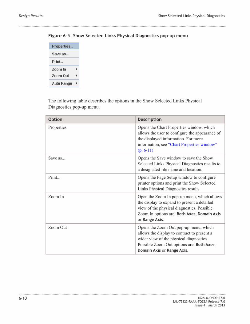
The following table describes the options in the Show Selected Links Physical
Diagnostics pop-up menu.
Option Description
Properties Opens the Chart Properties window, which
allows the user to configure the appearance of
the displayed information. For more
information, see “Chart Properties window”
(p. 6-11)
Save as... Opens the Save window to save the Show
Selected Links Physical Diagnostics results to
a designated file name and location.
Print... Opens the Page Setup window to configure
printer options and print the Show Selected
Links Physical Diagnostics results
Zoom In Open the Zoom In pop-up menu, which allows
the display to expand to present a detailed
view of the physical diagnostics. Possible
Zoom In options are: Both Axes, Domain Axis
or Range Axis.
Zoom Out Opens the Zoom Out pop-up menu, which
allows the display to contract to present a
wider view of the physical diagnostics.
Possible Zoom Out options are: Both Axes,
Domain Axis or Range Axis.
Figure 6-5 Show Selected Links Physical Diagnostics pop-up menu
Design Results Show Selected Links Physical Diagnostics
....................................................................................................................................................................................................................................
....................................................................................................................................................................................................................................
6-10 1626LM ONDP R7.0
3AL-75223-RAAA-TQZZA Release 7.0
Issue 4 March 2013

Option Description
Auto Range Opens the Auto Range pop-up menu, which
allows the display to contract or expand by
clicking in the window and dragging the
cursor to present the desired view of the
physical diagnostics. Possible Auto Range
options are: Both Axes, Domain Axis or Range
Axis.
Chart Properties window
The Chart Properties window enables the user to configure the appearance of the Show
Selected Links Physical Diagnostics results.
The Chart Properties window contains the following tabs:
• Figure 6-6, “Chart Properties window - Title tab” (p. 6-12) - configure the text and
font properties of the selected link or set of contiguous links in the Show Selected
Links Physical Diagnostics results windows.
• Figure 6-7, “Chart Properties window - Plot tab” (p. 6-13) - configure the color and
font properties of the labels, lines, axis, and background in the Show Selected Links
Physical Diagnostics results windows.
• Figure 6-8, “Chart Properties window - Other tab” (p. 6-14) - configure additional
color and font properties of the Show Selected Links Physical Diagnostics results
windows.
Design Results Show Selected Links Physical Diagnostics
....................................................................................................................................................................................................................................
....................................................................................................................................................................................................................................
1626LM ONDP R7.0
3AL-75223-RAAA-TQZZA Release 7.0
Issue 4 March 2013
6-11
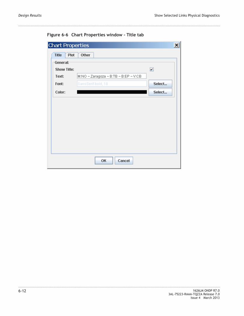
Figure 6-6 Chart Properties window - Title tab
Design Results Show Selected Links Physical Diagnostics
....................................................................................................................................................................................................................................
....................................................................................................................................................................................................................................
6-12 1626LM ONDP R7.0
3AL-75223-RAAA-TQZZA Release 7.0
Issue 4 March 2013

Figure 6-7 Chart Properties window - Plot tab
Design Results Show Selected Links Physical Diagnostics
....................................................................................................................................................................................................................................
....................................................................................................................................................................................................................................
1626LM ONDP R7.0
3AL-75223-RAAA-TQZZA Release 7.0
Issue 4 March 2013
6-13

Figure 6-8 Chart Properties window - Other tab
Design Results Show Selected Links Physical Diagnostics
....................................................................................................................................................................................................................................
....................................................................................................................................................................................................................................
6-14 1626LM ONDP R7.0
3AL-75223-RAAA-TQZZA Release 7.0
Issue 4 March 2013

Show Selected Links Real-Time Fast Feasibility Criteria
Description
The Show Selected Links Real-Time Fast Feasibility Criteria option on the Results menu
displays a window which graphically depicts the optical feasibility of a link between
nodes. The Fast Feasibility Criteria (FFC) depicted in the window has update capabilities.
For example, if the Loss parameter is changed, the optical margin is updated dynamically.
When the FFC is positive, the signal can travel from the source to the destination with a
margin indicated by the value of the FFC. When the FFC value is negative, the signal
cannot travel from the source to the destination without regeneration. In addition, the
absolute value of the FFC provides an indication of when the regeneration can be
removed. For example, an FFC value of –0.5 dB indicates regeneration removal is
possible soon, while an FFC value of –2 dB indicates regeneration removal is not possible
at all.
Access
The following are the methods to display the Real-Time Fast Feasibility Criteria.
1. From the Topology Map do the following:
• Right click a link to display the Link pop-up menu.
• Select Show Real-Time Fast Feasibility Criteria. The FFC is displayed.
2. From the Topology Map do the following:
• From the Icon bar, click the Optical Margin Tool icon.
• Mouse over any link on the map. The FFC is displayed.
3. From the Edit Spans window, do the following:
• Double click a link to display the Edit Spans window
• Right click the Links table to display the Links table pop-up menu
• From the Links pop-up menu, select Show Real-Time Fast Feasibility Criteria.
The FFC is displayed.
4. From the Main menu, do the following:
• Select a link or links on the Map
• From the Main menu, select Reports > Show Selected Links Real Time Fast
Feasibility Criteria. The FFC is displayed.
Design Results Show Selected Links Real-Time Fast Feasibility Criteria
....................................................................................................................................................................................................................................
....................................................................................................................................................................................................................................
1626LM ONDP R7.0
3AL-75223-RAAA-TQZZA Release 7.0
Issue 4 March 2013
6-15

Display
Figure 6-9 Real-Time Fast Feasibility Criteria – 10G
Figure 6-10 Real-Time Fast Feasibility Criteria – Mixed 10G/40G
Design Results Show Selected Links Real-Time Fast Feasibility Criteria
....................................................................................................................................................................................................................................
....................................................................................................................................................................................................................................
6-16 1626LM ONDP R7.0
3AL-75223-RAAA-TQZZA Release 7.0
Issue 4 March 2013

Show Graphical Statistics
Description
The Show Graphical Statistics report option displays the design results on the Topology
Map in a graphical display. The display changes based on the selection in the Statistics
window.
The Statistics window
The Statistics window allows various design statistics to display graphically on the
Topology Map for both Sites and Links.
For Sites, the following graphical design statistics are displayed:
• none
• Inputs
– Access Load
– Add Drop
• Nominal Outputs
– Transit OEO+OOO
– Transit OOO
– Transit OEO (3R+Re-color)
- Transit OEO (3R)
- Transit OEO (Re-color)
• Restoration Outputs
– Transit OEO (Restoration)
For Links, the following graphical design statistics are displayed:
• none
• Inputs
– Total Length
– Total Loss
– Spans Count
– Administrative Cost
• Nominal Outputs
– TrxA Optical Margin
– TrxA Non Feasible Optical Section
– Channels Count
• Restoration Outputs
– Channels Count
Design Results Show Graphical Statistics
....................................................................................................................................................................................................................................
....................................................................................................................................................................................................................................
1626LM ONDP R7.0
3AL-75223-RAAA-TQZZA Release 7.0
Issue 4 March 2013
6-17

Access
The following are the methods to display Graphical Statistics:
1. From the Main menu, do the following:
• Select Reports > Show Graphical Statistics.
• From the Statistics window, select the option button for the statistic you wish to
display graphically.
2. From the Topology Map, do the following:
• From the Icon Bar, click the Show Graphical Statistic icon.
• From the Statistics window, select the option button for the statistic you wish to
display graphically.
The Slide bar on the right side of the Statistics window increases or decreases graphically
on the Topology map the size of the currently selected statistic. As more statistics are
displayed on the Map, the statistical display can be increased or decreased so the various
graphics are easier to read.
Design Results Show Graphical Statistics
....................................................................................................................................................................................................................................
....................................................................................................................................................................................................................................
6-18 1626LM ONDP R7.0
3AL-75223-RAAA-TQZZA Release 7.0
Issue 4 March 2013

Display
The following are examples of the graphical display of selected statistics.
Figure 6-11 Spans Count graphical statistics example
Design Results Show Graphical Statistics
....................................................................................................................................................................................................................................
....................................................................................................................................................................................................................................
1626LM ONDP R7.0
3AL-75223-RAAA-TQZZA Release 7.0
Issue 4 March 2013
6-19

Figure 6-12 Access Load graphical statistics example
Design Results Show Graphical Statistics
....................................................................................................................................................................................................................................
....................................................................................................................................................................................................................................
6-20 1626LM ONDP R7.0
3AL-75223-RAAA-TQZZA Release 7.0
Issue 4 March 2013

Show Network Statistics
Description
The Show Network Statistics report option displays, for each step in the incremental
design, high level statistical values of the network design optimization, which provide the
user a global view of the network design. The report is presented in two screens:
• General Statistics - displays network statistics such as:
– number of failed connections
– number allocated optical bands
– fiber link load
– failure scenario, including number of dead and restored services
– number of NEs with 3R resources
• Statistics on Step - displays the following statistics on NEs and OMSs in the network
for each step in the incremental design
– Number of Nodes
– Number on OMSs
– Average Degree
– Maximum Degree
– Minimum Degree
Access
To access the Network Statistics report do the following:
• From the Main menu, select Reports > Show Network Statistics
• The Network Statistics report is displayed.
Design Results Show Network Statistics
....................................................................................................................................................................................................................................
....................................................................................................................................................................................................................................
1626LM ONDP R7.0
3AL-75223-RAAA-TQZZA Release 7.0
Issue 4 March 2013
6-21

Display
Figure 6-13 Network Statistics report - General Statistics tab
Design Results Show Network Statistics
....................................................................................................................................................................................................................................
....................................................................................................................................................................................................................................
6-22 1626LM ONDP R7.0
3AL-75223-RAAA-TQZZA Release 7.0
Issue 4 March 2013

Figure 6-14 Network Statistics report - Statistics on Step tab
Design Results Show Network Statistics
....................................................................................................................................................................................................................................
....................................................................................................................................................................................................................................
1626LM ONDP R7.0
3AL-75223-RAAA-TQZZA Release 7.0
Issue 4 March 2013
6-23

Show Failures Report
Description
The Show Failures Report report option indicates the effect of failures on the network.
This report has three tabs:
• Services – shows failure effects from a service point of view
• Scenarios – shows failure effects from a scenario point of view
• Filter – allows the user to select specific OMS, nodes, or SRGs to analyze for
failures.
By right-clicking on different fields in each tab, pop-up menus list the options available
for each field in the report. These pop-up menus provide the ability to display the
restoration paths, as well as the nominal and restoration paths for each scenario or each
service. Additionally, the user can highlight and navigate between the related objects, the
Topology map and the Edit Services window.
Summary button
The Summary button of each service or scenario provides a visual descriptive summary
for that service or scenario. It appears as a colored button containing three sections
separated by a slash (/) that indicate the status of the service or scenario, as appears in the
following figure:
The sections in the Summary button for services are as follows: xd/ymd/zr
• xd - the number (x) of services that are down (d)
• ymd - the number (y) of services restored with at least one partial disjointness rule
violation for at least one service (most disjointness - md)
• zr - the number (z) of services restored (r) without any partial disjointness rule
violation
The sections in the Summary button for scenarios are as follows: xd/ymd/zr
• xd - the number (x) of scenarios that are down (d)
• ymd - the number (y) of scenarios restored with at least one partial disjointness rule
violation (most disjointness - md)
• zr - the number (z) of scenarios restored (r) without any partial disjointness rule
violation
Figure 6-15 Service Summary button
Design Results Show Failures Report
....................................................................................................................................................................................................................................
....................................................................................................................................................................................................................................
6-24 1626LM ONDP R7.0
3AL-75223-RAAA-TQZZA Release 7.0
Issue 4 March 2013

Tab color description
The colors displayed on Services tab indicate the following conditions:
• Green - for all involved failures, the service is Restored without any partial
disjointness rule violation
• Red - the service is down for at least one involved failure
• Blue - for all involved failures, the service is Restored with at least one partial
disjointness rule violation
The colors displayed on Scenarios tab indicate the following conditions:
• Green - for all involved services, the failure scenario induces successful restoration
without any partial disjointness rule violation
• Red - at least one service is down for that failure scenario
• Blue - for all involved services, the failure scenario induces at least one Restoration
with at least one partial disjointness rule violation (but no service is down for that
failure scenario)
Access
To access the Failures Report do the following:
• From the Main menu, select Reports > Show Failures Report
• The Failures Report window is displayed. The Services tab is the default display.
Display
The Failures Report contains three tabs: Services, Scenarios, and Filter.
Failures Report, Services tab
The Services tab of the Show Failures Report lists failures on services in a hierarchical
tree. Right-click on each level in the tree to display a pop-up menu of available
commands for that level. For a list of commands descriptions, see “Failures Report
pop-up menus commands” (p. 6-29).
Design Results Show Failures Report
....................................................................................................................................................................................................................................
....................................................................................................................................................................................................................................
1626LM ONDP R7.0
3AL-75223-RAAA-TQZZA Release 7.0
Issue 4 March 2013
6-25

Services Summary icon - the top icon of the hierarchical tree in the Services tab provides
a visual descriptive summary of services. The icon appears as a colored button followed
by three section separated by a slash (/), The sections in the icon appear as follows:
ad/bmd/cr, where
• ad - the number (a) of services that are down
• bmd - the number (b) of services that are Restored with at least one partial
disjointness rule violation for at least one service
• cr - the number (c) of services that are Restored without any partial disjointness rule
violation
Figure 6-16 Failures Report, Services tab
Design Results Show Failures Report
....................................................................................................................................................................................................................................
....................................................................................................................................................................................................................................
6-26 1626LM ONDP R7.0
3AL-75223-RAAA-TQZZA Release 7.0
Issue 4 March 2013

Services Summary icon colors - the colors displayed in the top icon of the hierarchical
tree in the Services tab indicate the following conditions
• Green - all services are Restored without any partial disjointness rule violation
• Red - at least one service is Down
• Blue - all services are Restored with at least one partial disjointness rule violation for
at least one service
Failures Report, Scenarios tab
The Scenaros tab of the Show Failures Report lists failures on services from a failure
scenario perspective in a hierarchical tree. Right-click on each level in the tree to display
a pop-up menu of available commands for that level. For a list of commands descriptions,
see “Failures Report pop-up menus commands” (p. 6-29).
Figure 6-17 Failures Report, Scenarios tab
Design Results Show Failures Report
....................................................................................................................................................................................................................................
....................................................................................................................................................................................................................................
1626LM ONDP R7.0
3AL-75223-RAAA-TQZZA Release 7.0
Issue 4 March 2013
6-27

Scenarios Summary icon - the top icon of the hierarchical tree in the Scenarios tab
provides a visual descriptive summary of failure scenarios. The icon appears as a colored
button followed by three section separated by a slash (/), The sections in the icon appear
as follows: ad/bmd/cr, where
• ad - the number (a) of failure scenarios that are down
• bmd - the number (b) of failure scenarios that are Restored with at least one partial
disjointness rule violation for at least one service
• cr - the number (c) of failure scenarios that induce successful Restoration without any
partial disjointness rule violation
Scenarios Summary icon colors - the colors displayed in the top icon of the hierarchical
tree in the Services tab indicate the following conditions
• Green - all services are Restored without any partial disjointness rule violation
• Red - at least one service is Down
• Blue - all services are Restored with at least one partial disjointness rule violation for
at least one service
Failures Report, Filter tab
The Filter tab of the Failures Report allows the failures analysis to be filtered for specific
resources. To include or exclude resources, highlight the resource(s) and click the right or
left arrow button.
Design Results Show Failures Report
....................................................................................................................................................................................................................................
....................................................................................................................................................................................................................................
6-28 1626LM ONDP R7.0
3AL-75223-RAAA-TQZZA Release 7.0
Issue 4 March 2013

Failures Report pop-up menus commands
The following table describe the commands that are appear in the various pop-up menus
in the Failures Report. The commands that display are specific to the position in the
hierarchical tree. All commands do not appear in all pop-up menus. To display the pop-up
menu, right click in the tree.
Command Description
Expand All Expand the tree to display all information to the
lowest level
Collapse All Collapse the tree to the highest level of
information
Highlight All Nominal on Map Highlight all the nominal services on the
Topology Map
Figure 6-18 Failures Report, Filter tab
Design Results Show Failures Report
....................................................................................................................................................................................................................................
....................................................................................................................................................................................................................................
1626LM ONDP R7.0
3AL-75223-RAAA-TQZZA Release 7.0
Issue 4 March 2013
6-29

Command Description
Highlight Nominal on Map Highlight the specific nominal services on the
Topology Map
Highlight in Table Open the Edit Service window and display the
highlighted service(s) in the table
Highlight All Restored on Map Highlight all restored services on the Topology
Map
Highlight Restored on Map Highlight the specific restored services on the
Topology Map
Highlight Nominal + Restored on Map Highlight the specific nominal and restored
services on the Topology Map
Navigate to From the Services tab, navigate from the specific
service to the scenario in the Scenario tab. From
the Scenario tab, navigate from the scenario to
the service in the Services tab.
Highlight All on Map Highlight all failed resources on the Topology
Map.
Highlight on Map Highlight the specific failed resources on the
Topology Map.
Design Results Show Failures Report
....................................................................................................................................................................................................................................
....................................................................................................................................................................................................................................
6-30 1626LM ONDP R7.0
3AL-75223-RAAA-TQZZA Release 7.0
Issue 4 March 2013

Show GMRE Audit Logs
Description
The GMRE Audit Logs report displays the results of the restoration and protection
analysis/failure analysis.
Access
To access the GMRE Audit Logs report do one of the following:
• From the Main menu, select Tools > GMRE Simulator. The report is displayed
• From the Main menu, select Reports > Show GMRE Audit Logs
Display
The information reported on the GMRE Audit Logs report is determined by the type of
scenario in which the GMRE Simulator used. The following links proved detailed
information on the GMRE Simulator use case scenarios.
• “GMRE Simulator use case 1 — determine success of GMPLS dimensioning”
(p. 7-9)
• “GMRE Simulator use case 2 — evaluate tolerance of GMPLS restoration
dimensioning” (p. 7-10)
Display
The information reported on the GMRE Audit Logs report is determined by the type of
scenario in which the GMRE Simulator is used. The following sections proved detailed
information on the GMRE Simulator use case scenarios and the information that is
displayed on the GMRE Audit Logs reports for each use case.
GMRE Simulator — determine success of GMPLS dimensioning
In this use case, failure scenarios are simulated and the results allow the user to determine
if it is possible to restore successfully or if there are errors in the GMPLS dimensioning.
For more information, see “GMRE Simulator use case 1 — determine success of GMPLS
dimensioning” (p. 7-9).
Design Results Show GMRE Audit Logs
....................................................................................................................................................................................................................................
....................................................................................................................................................................................................................................
1626LM ONDP R7.0
3AL-75223-RAAA-TQZZA Release 7.0
Issue 4 March 2013
6-31

GMRE Audit Logs report — evaluate tolerance of GMPLS restoration dimensioning
In this use case, the GMRE simulator is used to evaluate the tolerance of GMPLS
restoration dimensioning. For more information, see “GMRE Simulator use case 2 —
evaluate tolerance of GMPLS restoration dimensioning” (p. 7-10).
Figure 6-19 GMRE Audit Logs report — determining success of GMPLS dimensioning
Design Results Show GMRE Audit Logs
....................................................................................................................................................................................................................................
....................................................................................................................................................................................................................................
6-32 1626LM ONDP R7.0
3AL-75223-RAAA-TQZZA Release 7.0
Issue 4 March 2013

Figure 6-20 GMRE Audit Logs report — evaluate tolerance of GMPLS restoration
dimensioning
Design Results Show GMRE Audit Logs
....................................................................................................................................................................................................................................
....................................................................................................................................................................................................................................
1626LM ONDP R7.0
3AL-75223-RAAA-TQZZA Release 7.0
Issue 4 March 2013
6-33

Show Traffic Design Logs
Description
The Show Traffic Design Logs report option displays logs on the network design.
Access
To access the Traffic design logs report do the following:
• From the Main menu, select Reports > Show Traffic Design Logs
• The Traffic design logs report is displayed.
Display
Figure 6-21 Traffic design logs report
Design Results Show Traffic Design Logs
....................................................................................................................................................................................................................................
....................................................................................................................................................................................................................................
6-34 1626LM ONDP R7.0
3AL-75223-RAAA-TQZZA Release 7.0
Issue 4 March 2013

Show Errors Report
Description
The Show Errors Report option produces the List Errors report, which provides
information about warning messages and errors generated while running the network
design. These errors are reported for either network calculation or optical line design
errors.
Access
The List Errors report is displayed in the following ways:
• From the Main menu, select Reports > Show Errors Report
• If errors occur when running the network design, the report is displayed automatically.
For more information on how to run the network design, see Chapter 5, “ Run the
Network Design”.
Display
Figure 6-22 List Errors report
Design Results Show Errors Report
....................................................................................................................................................................................................................................
....................................................................................................................................................................................................................................
1626LM ONDP R7.0
3AL-75223-RAAA-TQZZA Release 7.0
Issue 4 March 2013
6-35

Errors list
The following is a list of possible errors reported while running the network design.
Table 6-2 List of reported network design errors
General Information Detailed
Information
Type Domain Severity
Network optimization
failed
No physical path found Design Network Critical
Network optimization
failed
Wavelength allocation
failed
Design Network Critical
Network optimization
failed
Disjoint path not found Design Network Critical
Network optimization
failed
Constraint not fulfilled Design Network Critical
Network optimization
failed
Service path
reservation failed
Design Network Critical
Network optimization
failed
Error in service
constraint loading
Design Network Critical
Optical line
optimization failed
Span too short Design Optical line Critical
Optical line
optimization failed
Span too long Design Optical line Critical
Optical line
optimization failed
Equipment not
recognized
Design Optical line Critical
SRG Violation At least one restoration
scenario cannot fulfill
SRG constraints for
service
Network Design Warning
Disjointness violation
on links / nodes
Nominal paths partial
disjointness between
services S1 and S2
Network Design Warning
Disjointness violation
on links / nodes
Nominal paths partial
disjointness between
working and protecting
paths
Network Design Warning
Design Results Show Errors Report
....................................................................................................................................................................................................................................
....................................................................................................................................................................................................................................
6-36 1626LM ONDP R7.0
3AL-75223-RAAA-TQZZA Release 7.0
Issue 4 March 2013

Show Bill of Material
Description
The Show Bill of Material report option displays the list of materials needed to construct
the network.
Access
To access the Bill of Materials report do the following:
• From the Main menu, select Reports > Show Bill of Material
• The Bill of Material report is displayed.
Display
Figure 6-23 Bill of Material report
Design Results Show Bill of Material
....................................................................................................................................................................................................................................
....................................................................................................................................................................................................................................
1626LM ONDP R7.0
3AL-75223-RAAA-TQZZA Release 7.0
Issue 4 March 2013
6-37

Show Bill of Material (multi-step)
Description
The Show Bill of Material (multi-step) report option displays the list of materials needed
to construct the network for each step in the incremental design, for a series of steps in the
incremental design, or for the whole design.
The report provides Start step and End step sliders. When the two sliders have the same
value the entire Bill of Material is displayed for the chosen step. When the values of the
sliders are different, the Bill of Material for the chosen End step, beginning from the
chosen Start step is displayed.
Access
To access the Incremental Bill of Material report do the following:
• From the Main menu, select Reports > Show Bill of Material (multi-step)
• The Incremental Bill of Material report is displayed.
Display
Figure 6-24 Incremental Bill of Material report
Design Results Show Bill of Material (multi-step)
....................................................................................................................................................................................................................................
....................................................................................................................................................................................................................................
6-38 1626LM ONDP R7.0
3AL-75223-RAAA-TQZZA Release 7.0
Issue 4 March 2013

Show Sites/Part List
Description
The Show Sites/Part List report option displays the list of boards for each NE with
location and optical parameters.
Access
The following are methods to display the Sites/Part List
1. From the Main menu, select Reports > Show Sites/Part List
2. From the Topology Map, do the following:
• Right-click a Site
• From the Site pop-up menu, select Show Part List
Display
Figure 6-25 Part List report
Design Results Show Sites/Part List
....................................................................................................................................................................................................................................
....................................................................................................................................................................................................................................
1626LM ONDP R7.0
3AL-75223-RAAA-TQZZA Release 7.0
Issue 4 March 2013
6-39

Show Equipment View
Description
The Show Equipment View option displays the view of the specific equipment. Shelf
modifications are supported through this window. For more information on shelf
modifications, see Chapter 8, “Modifications for ONDP Design”.
Access
To display the Equipment View do the following:
• From the Topology Map, click a site to display the Site pop-up menu.
• From the Site pop-up menu, select Show Equipment View.
• To toggle to the Schematic View, select Display from the menu, and check/uncheck
the Schematic View box.
Display
Figure 6-26 Edit Equipments report
Design Results Show Equipment View
....................................................................................................................................................................................................................................
....................................................................................................................................................................................................................................
6-40 1626LM ONDP R7.0
3AL-75223-RAAA-TQZZA Release 7.0
Issue 4 March 2013

Show Line View
Description
The Show Line View options display the path followed by all wavelengths supported by
the link.
The report permits the following views:
• Show Line View (full spectrum) - displays the channels carried by the selected link
in their respective wavelength/frequency order in the optical spectrum. This view
could lead to a complex graphical display.
• Show Line View (optimized) - displays the channels in a reordered way so that the
graphical display is optimally simplified.
Both the Show Line View (full spectrum) and the Show Line View (optimized) option
provides the following graphical display options:
• Display “ITU Id”
• Display “Frequency”
• Display “Wavelength”
• Display “ITU Id/Frequencies”
• Display “ITU Id/Wavelength”
• Display “ITU Id/Protection”
• Display “ITU Id/Trib”
• Display “ITU Id/Location”
• Display “ITU Id/WDM Format”
• Display “ITU Id/Service Label”
Access
To display the Line View do the following:
• From the Topology Map, right click a link to display the Link pop-up menu.
• Select either Show Line View (full spectrum) or Show Line View (optimized)
• To change the information displayed, select Display from the main menu and select
the option button of the desired view from the drop-down menu, as shown in Figure
6-27, “Show Line View Display options” (p. 6-42)..
Design Results Show Line View
....................................................................................................................................................................................................................................
....................................................................................................................................................................................................................................
1626LM ONDP R7.0
3AL-75223-RAAA-TQZZA Release 7.0
Issue 4 March 2013
6-41

Display the Ports View window
From the Line View window do the following to access the Ports View window.
• From the Line View window, click the desired channel for which to display the Ports
View window. The rest of the window will be greyed out and the Open command on
the Main menu will become active.
• From the Line View Main menu, select Open.
• From the Open menu, select either Source Port Window to open the Ports View
window for the source port, or Destin Port Window to open the Port View window
for the destination port. The Ports View window is displayed, if the channel
transmission is made through a concentrator. For more information on the Ports View
window, see “Ports View window” (p. 8-16).
Figure 6-27 Show Line View Display options
Design Results Show Line View
....................................................................................................................................................................................................................................
....................................................................................................................................................................................................................................
6-42 1626LM ONDP R7.0
3AL-75223-RAAA-TQZZA Release 7.0
Issue 4 March 2013

Show Line View display
Figure 6-28 Line View (full spectrum) report
Design Results Show Line View
....................................................................................................................................................................................................................................
....................................................................................................................................................................................................................................
1626LM ONDP R7.0
3AL-75223-RAAA-TQZZA Release 7.0
Issue 4 March 2013
6-43
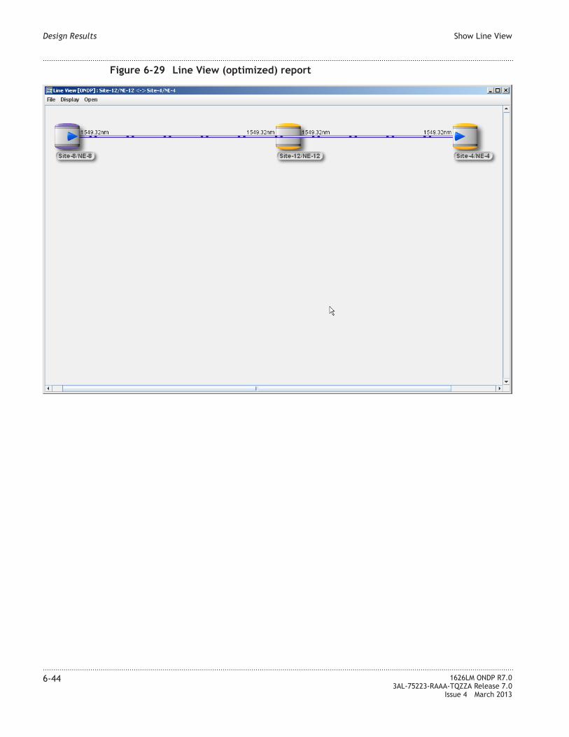
Figure 6-29 Line View (optimized) report
Design Results Show Line View
....................................................................................................................................................................................................................................
....................................................................................................................................................................................................................................
6-44 1626LM ONDP R7.0
3AL-75223-RAAA-TQZZA Release 7.0
Issue 4 March 2013

Export Design Results Excel Report
Description
The Export Design Results Excel Report option produces a Network Descriptions Table
file in Excel format which can be used for manual commissioning. The Excel Export
Filtering window allows the user to select the specific data to export to the Network
Design Table.
Additionally, the file gathers all the network design input and output results such as
network topology, traffic matrix, service route information (nominal and restored), optical
margin per service and line design information. All the necessary network data (input &
output) are included in a unique file.
Access
To export the file, do the following:
• From the Main menu, select Reports > Export Design Results Excel Report
Figure 6-30 Excel Export Filtering window
Design Results Export Design Results Excel Report
....................................................................................................................................................................................................................................
....................................................................................................................................................................................................................................
1626LM ONDP R7.0
3AL-75223-RAAA-TQZZA Release 7.0
Issue 4 March 2013
6-45

Note: If a full design has not been run, a Warning box displays the message
Network inputs have been modified. You need to rerun a full
design. If you decide to continue there will be no guarantee
on the output. Click Continue.
Result: The Excel Export Filtering window is displayed.
• Select the data to be exported and click Apply.
Result: The Export to Excel window is displayed.
• Navigate to the folder in which the NDT will be saved, and click Save.
Result: The report file is saved in .xls format in the selected folder.
Display
The Export Design Results report produces an Excel file, which presents the Network
Descriptions Table in an Excel spreadsheet. The follow table lists the tabs in the
spreadsheet.
Export Design Results tab title Description
Figure 6-31, “Descriptive Sheet tab”
(p. 6-48)
Displays high level information describing the
network
Figure 6-32, “Map tab” (p. 6-49) Displays the network as seen on the Topology
Map
Figure 6-33, “Sites tab” (p. 6-50) Displays a list of the sites and the site parameters
Figure 6-34, “Links tab” (p. 6-51) Displays a list of the links and link parameters.
This tab also contains links to spans details tabs.
Figure 6-35, “Relations tab” (p. 6-52) Displays a list of the relations and relation
parameters. This tab also contains links to
services details tabs
Figure 6-36, “BOM tab” (p. 6-53) Displays a Bill of Materials report for the
network
Figure 6-37, “Part List Sites tab” (p. 6-54) Displays a list of sites with links to tabs which
contain Part Lists for each site.
Figure 6-38, “Design Service Summary
tab” (p. 6-55)
Displays a list of parameters summarizing the
service design result
Figure 6-39, “Restoration tab” (p. 6-56) Displays restoration information for services
Figure 6-40, “Graph Statistics tab”
(p. 6-57)
Displays a Graphical Statistics report in
spreadsheet format
Figure 6-47, “Network Design Logs tab”
(p. 6-64)
Displays log information on the network design
Figure 6-41, “Inter-NE Links, LT and Node
tab” (p. 6-58)
Displays optical data of links and nodes
Design Results Export Design Results Excel Report
....................................................................................................................................................................................................................................
....................................................................................................................................................................................................................................
6-46 1626LM ONDP R7.0
3AL-75223-RAAA-TQZZA Release 7.0
Issue 4 March 2013

Export Design Results tab title Description
Figure 6-42, “NE Parameters tab” (p. 6-59) Displays a listing of the NE parameters
Figure 6-43, “Subsets tab” (p. 6-60) Displays information about Subsets
Figure 6-44, “GMPLS Link Optical
Parameters tab” (p. 6-61)
Displays the GMPLS attributes for each OMS
link in the network
Figure 6-45, “GMPLS AddDropType per
Site” (p. 6-62)
Displays all the possible AddDropType
references that could be used in the current
network, considering if the 100 G Coherent
format is or is not forecast in the current network
design.
Figure 6-46, “SRG tab” (p. 6-63) Displays information about SRGs
Figure 6-47, “Network Design Logs tab”
(p. 6-64)
Displays the network design logs
Figure 6-48, “OSNR NLP tab” (p. 6-65) Displays OSNR NLP evolution along a service
path
Figure 6-49, “CD tab” (p. 6-66) Displays a chromatic dispersion report
Figure 6-50, “PL Site X tab” (p. 6-67) Displays a schematic view and a detailed part list
of the equipment. This tab contains a link to the
Part List Sites tab. There is a separate tab for each
site.
Figure 6-51, “SP Site-X Site-X tab”
(p. 6-68)
Displays the span information between two sites.
There is a separate tab for each link.
Figure 6-52, “Ser Site-X Site-X” (p. 6-69) Displays service information for each relation.
There is a separate tab for each relation.
Figure 6-53, “DSF Mask 2 Forghieri grids
tab” (p. 6-70)
Displays the frequency information for the DSF
mask 2 Forghieri grids
Design Results Export Design Results Excel Report
....................................................................................................................................................................................................................................
....................................................................................................................................................................................................................................
1626LM ONDP R7.0
3AL-75223-RAAA-TQZZA Release 7.0
Issue 4 March 2013
6-47

Figure 6-31 Descriptive Sheet tab
Design Results Export Design Results Excel Report
....................................................................................................................................................................................................................................
....................................................................................................................................................................................................................................
6-48 1626LM ONDP R7.0
3AL-75223-RAAA-TQZZA Release 7.0
Issue 4 March 2013

Figure 6-32 Map tab
Design Results Export Design Results Excel Report
....................................................................................................................................................................................................................................
....................................................................................................................................................................................................................................
1626LM ONDP R7.0
3AL-75223-RAAA-TQZZA Release 7.0
Issue 4 March 2013
6-49

Figure 6-33 Sites tab
Design Results Export Design Results Excel Report
....................................................................................................................................................................................................................................
....................................................................................................................................................................................................................................
6-50 1626LM ONDP R7.0
3AL-75223-RAAA-TQZZA Release 7.0
Issue 4 March 2013

Figure 6-34 Links tab
Design Results Export Design Results Excel Report
....................................................................................................................................................................................................................................
....................................................................................................................................................................................................................................
1626LM ONDP R7.0
3AL-75223-RAAA-TQZZA Release 7.0
Issue 4 March 2013
6-51

Figure 6-35 Relations tab
Design Results Export Design Results Excel Report
....................................................................................................................................................................................................................................
....................................................................................................................................................................................................................................
6-52 1626LM ONDP R7.0
3AL-75223-RAAA-TQZZA Release 7.0
Issue 4 March 2013

Figure 6-36 BOM tab
Design Results Export Design Results Excel Report
....................................................................................................................................................................................................................................
....................................................................................................................................................................................................................................
1626LM ONDP R7.0
3AL-75223-RAAA-TQZZA Release 7.0
Issue 4 March 2013
6-53

Figure 6-37 Part List Sites tab
Design Results Export Design Results Excel Report
....................................................................................................................................................................................................................................
....................................................................................................................................................................................................................................
6-54 1626LM ONDP R7.0
3AL-75223-RAAA-TQZZA Release 7.0
Issue 4 March 2013

Figure 6-38 Design Service Summary tab
Design Results Export Design Results Excel Report
....................................................................................................................................................................................................................................
....................................................................................................................................................................................................................................
1626LM ONDP R7.0
3AL-75223-RAAA-TQZZA Release 7.0
Issue 4 March 2013
6-55

Figure 6-39 Restoration tab
Design Results Export Design Results Excel Report
....................................................................................................................................................................................................................................
....................................................................................................................................................................................................................................
6-56 1626LM ONDP R7.0
3AL-75223-RAAA-TQZZA Release 7.0
Issue 4 March 2013

Figure 6-40 Graph Statistics tab
Design Results Export Design Results Excel Report
....................................................................................................................................................................................................................................
....................................................................................................................................................................................................................................
1626LM ONDP R7.0
3AL-75223-RAAA-TQZZA Release 7.0
Issue 4 March 2013
6-57

Figure 6-41 Inter-NE Links, LT and Node tab
Design Results Export Design Results Excel Report
....................................................................................................................................................................................................................................
....................................................................................................................................................................................................................................
6-58 1626LM ONDP R7.0
3AL-75223-RAAA-TQZZA Release 7.0
Issue 4 March 2013

Figure 6-42 NE Parameters tab
Design Results Export Design Results Excel Report
....................................................................................................................................................................................................................................
....................................................................................................................................................................................................................................
1626LM ONDP R7.0
3AL-75223-RAAA-TQZZA Release 7.0
Issue 4 March 2013
6-59

Figure 6-43 Subsets tab
Design Results Export Design Results Excel Report
....................................................................................................................................................................................................................................
....................................................................................................................................................................................................................................
6-60 1626LM ONDP R7.0
3AL-75223-RAAA-TQZZA Release 7.0
Issue 4 March 2013
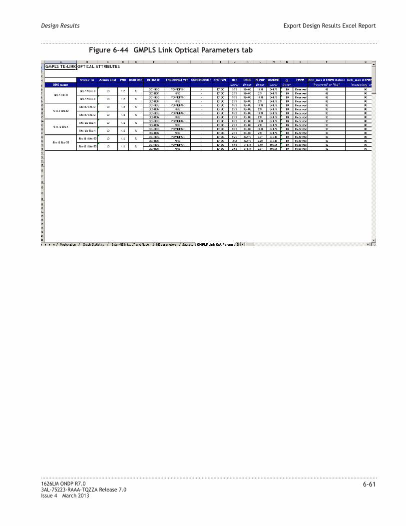
Figure 6-44 GMPLS Link Optical Parameters tab
Design Results Export Design Results Excel Report
....................................................................................................................................................................................................................................
....................................................................................................................................................................................................................................
1626LM ONDP R7.0
3AL-75223-RAAA-TQZZA Release 7.0
Issue 4 March 2013
6-61

Figure 6-45 GMPLS AddDropType per Site
Design Results Export Design Results Excel Report
....................................................................................................................................................................................................................................
....................................................................................................................................................................................................................................
6-62 1626LM ONDP R7.0
3AL-75223-RAAA-TQZZA Release 7.0
Issue 4 March 2013

Figure 6-46 SRG tab
Design Results Export Design Results Excel Report
....................................................................................................................................................................................................................................
....................................................................................................................................................................................................................................
1626LM ONDP R7.0
3AL-75223-RAAA-TQZZA Release 7.0
Issue 4 March 2013
6-63

Figure 6-47 Network Design Logs tab
Design Results Export Design Results Excel Report
....................................................................................................................................................................................................................................
....................................................................................................................................................................................................................................
6-64 1626LM ONDP R7.0
3AL-75223-RAAA-TQZZA Release 7.0
Issue 4 March 2013
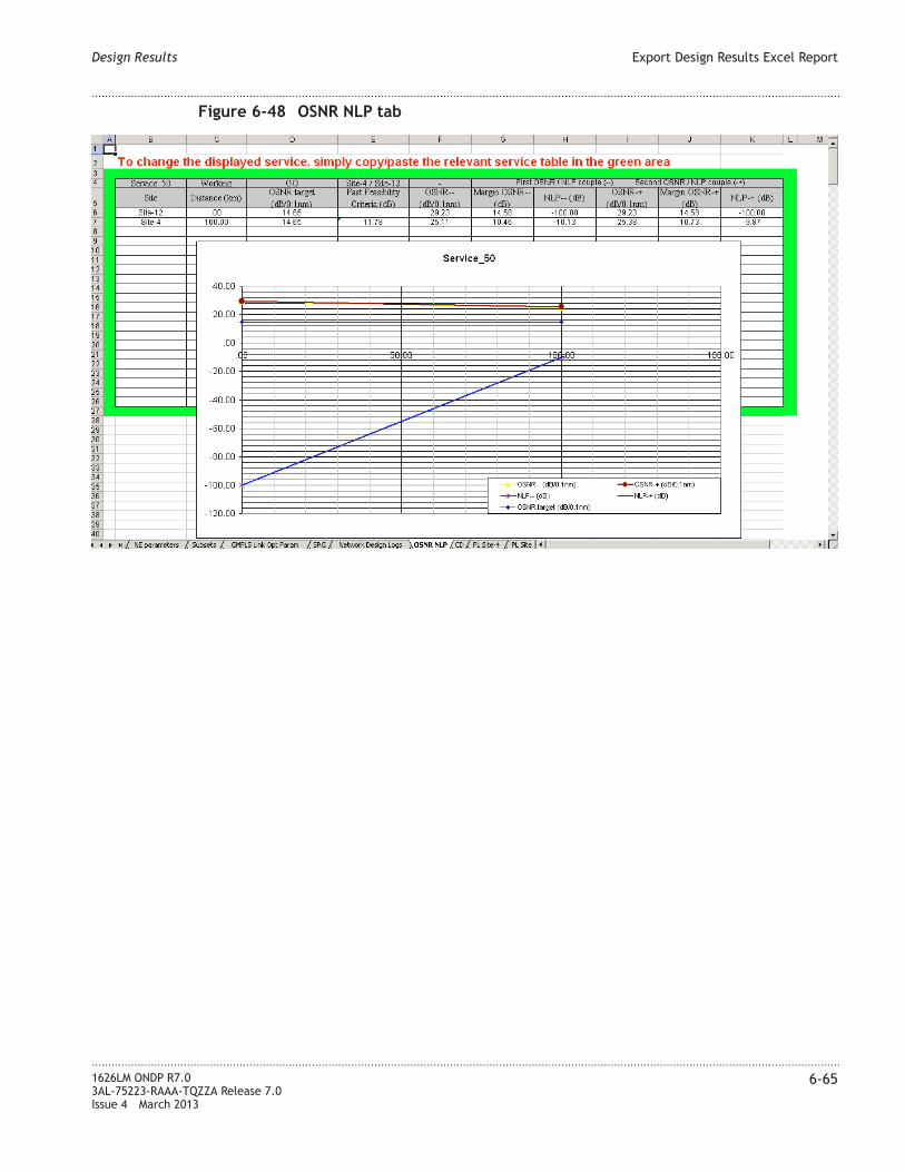
Figure 6-48 OSNR NLP tab
Design Results Export Design Results Excel Report
....................................................................................................................................................................................................................................
....................................................................................................................................................................................................................................
1626LM ONDP R7.0
3AL-75223-RAAA-TQZZA Release 7.0
Issue 4 March 2013
6-65

Figure 6-49 CD tab
Design Results Export Design Results Excel Report
....................................................................................................................................................................................................................................
....................................................................................................................................................................................................................................
6-66 1626LM ONDP R7.0
3AL-75223-RAAA-TQZZA Release 7.0
Issue 4 March 2013

Figure 6-50 PL Site X tab
Design Results Export Design Results Excel Report
....................................................................................................................................................................................................................................
....................................................................................................................................................................................................................................
1626LM ONDP R7.0
3AL-75223-RAAA-TQZZA Release 7.0
Issue 4 March 2013
6-67

Figure 6-51 SP Site-X Site-X tab
Design Results Export Design Results Excel Report
....................................................................................................................................................................................................................................
....................................................................................................................................................................................................................................
6-68 1626LM ONDP R7.0
3AL-75223-RAAA-TQZZA Release 7.0
Issue 4 March 2013

Figure 6-52 Ser Site-X Site-X
Design Results Export Design Results Excel Report
....................................................................................................................................................................................................................................
....................................................................................................................................................................................................................................
1626LM ONDP R7.0
3AL-75223-RAAA-TQZZA Release 7.0
Issue 4 March 2013
6-69

Figure 6-53 DSF Mask 2 Forghieri grids tab
Design Results Export Design Results Excel Report
....................................................................................................................................................................................................................................
....................................................................................................................................................................................................................................
6-70 1626LM ONDP R7.0
3AL-75223-RAAA-TQZZA Release 7.0
Issue 4 March 2013

Export BoM
Description
The Export BoM produces output to the Comet software for automatic quotation based on
the BoM.
Access
To export the file, do the following:
• From the Main menu, select Reports > Export BoM
Note: If a full design has not been run, a Warning box displays the message
Network inputs have been modified. You need to rerun a full
design. If you decide to continue there will be no guarantee
on the output. Click Continue.
Result: A Warning box displays the message File nn_BoM.xls will be
created in the current folder. nn is the name of the current project.
• Click Continue.
Result: The ONDP dialog box is displayed.
• Navigate to the folder in which the Export BOM report will be saved.
• In the File Name field, rename the file if desired, or accept the default file name.
• Click Save.
Result: The Export BOM report is saved in .xls format in the selected folder.
Design Results Export BoM
....................................................................................................................................................................................................................................
....................................................................................................................................................................................................................................
1626LM ONDP R7.0
3AL-75223-RAAA-TQZZA Release 7.0
Issue 4 March 2013
6-71

Display
Figure 6-54 Export BoM report
Design Results Export BoM
....................................................................................................................................................................................................................................
....................................................................................................................................................................................................................................
6-72 1626LM ONDP R7.0
3AL-75223-RAAA-TQZZA Release 7.0
Issue 4 March 2013

7 7Network Analysis: Audit
and Upgrade
Overview
Purpose
This chapter provides information on performing network analysis operations on an
existing network.
Contents
Network Configuration in ONDP 7-2
Network Analysis: Audit 7-4
Network Analysis: Upgrade 7-7
Audit: Failure and Restoration Analysis — GMRE Simulator 7-9
...................................................................................................................................................................................................................................
1626LM ONDP R7.0
3AL-75223-RAAA-TQZZA Release 7.0
Issue 4 March 2013
7-1

Network Configuration in ONDP
Overview
ONDP users are able to perform network analysis functions such as auditing the network
and performing upgrades of network resources. These types of analysis can be performed
on a network created in ONDP or on an existing network that is loaded into ONDP.
The following is a list of types of network analysis ONDP is able to perform:
• Service path analysis – determine optical feasibility
• Restoration analysis – upon possible failures, determine the survivability of services
• Network statistics analysis – determine load requirements and identify bottlenecks or
weaknesses
• Perform scenarios for specific failures or network changes (upgrade)
Methods to create and configure a network
The following are the methods of creating and configuring a network in ONDP.
• “Full manual network creation” (p. 7-2) – using the design inputs described in this
guide, manually create a network from scratch by adding all the design elements and
setting all the parameters. The network created is saved in ONDP as a .ondp file.
• “Semi-auto network creation” (p. 7-3) – load and use a previously created .ondp file
and manually update and fine tune network parameters. For more information, see
“Open an Existing Project (.ondp file)” (p. 4-11).
Full manual network creation
Manually building a network from scratch requires that the user configure the following:
• “Network topology – create links and nodes” (p. 7-2)
• “NE configuration – set board type and shelf location” (p. 7-3)
• “Optical line configuration – set line tuning parameters” (p. 7-3)
• “Service demands – set spatial and spectral routes” (p. 7-3)
Network topology – create links and nodes
The user begins building a network by creating nodes and configuring the links between
the nodes. Parameters for the links are set at the link level as either input data or shown as
output results, which are computed by ONDP after the design is run.
For detailed information on creating nodes and configuring links, see Chapter 4, “Design
Inputs”. For detailed information on design outputs, see Chapter 6, “Design Results”
Network Analysis: Audit and Upgrade Network Configuration in ONDP
....................................................................................................................................................................................................................................
....................................................................................................................................................................................................................................
7-2 1626LM ONDP R7.0
3AL-75223-RAAA-TQZZA Release 7.0
Issue 4 March 2013

NE configuration – set board type and shelf location
Currently, board type and shelf location are not manually configured in ONDP. However,
after running the design, the software provides a standard shelf configuration, which is
used when upgrading a network. When doing an upgrade, new resources are identified to
distinguish them from existing resources. The user must rearrange the shelf configuration
for the existing boards to match the ones installed in the field, if they are different than
the standard shelf provided by ONDP.
Optical line configuration – set line tuning parameters
For the optical line configuration, the user sets the line tuning parameters for all optical
lines, using the Edit route optical design window. The following are examples of line
tuning parameters.
• LOFA type
• Output power
• DCU type
• DCU length
• Fixed Optical Attenuator
For information on the Edit route optical design window, see “Show/Tune Selected Links
Design ” (p. 6-3).
Service demands – set spatial and spectral routes
To set the service demand, the user sets the spatial and spectral route constraints, as well
as the 3R/recoloring points.
The explicit routing constraints are the full descriptions of the paths either at the
physical/link layer (spatial path) or the lambda layer (spectral path). Explicit routing
constraints are required for setting the manual service route during existing network
creation. Explicit routing constraints are also required for wavelength preference support
when creating a network or upgrading an existing network.
For information on explicit routing constraints, see “Relations and Services” (p. 4-57) and
“Edit Spatial and Spectral Constraints” (p. 4-86).
For 3R points, the default nominal path is set by specifying on which NE in the path the
WDM channel needs to be regenerated.
Semi-auto network creation
In semi-auto network creation, a previously created .ondp file is loaded to manually
update and fine tune network parameters. For more information, see “Open an Existing
Project (.ondp file)” (p. 4-11). After the existing network file is loaded, the existing
network resources are set and fine tuned as described in “Full manual network creation”
(p. 7-2).
Network Analysis: Audit and Upgrade Network Configuration in ONDP
....................................................................................................................................................................................................................................
....................................................................................................................................................................................................................................
1626LM ONDP R7.0
3AL-75223-RAAA-TQZZA Release 7.0
Issue 4 March 2013
7-3

Network Analysis: Audit
Audit overview
The audit process is controlled through the use of a design mode parameter set on the
topology resources (links and nodes) and path constraints set on services.
Set Computation Mode parameter
The design mode parameter that is used to define how the audit process is controlled on a
resource is the Computation Mode parameter, located on the Edit Spans window. The
possible values of the Computation Mode parameter are:
• Automatic – hardware and tuning are automatically set by ONDP. Elements with this
setting are designed automatically.
• Semi-Auto – hardware data is input by the user. Tuning is automatically set by ONDP.
• Manual – hardware and tuning data are input by the user and are used by ONDP as is.
No optimization or design is performed on elements with this setting. Only an audit
and checking process is performed
• NLP/OSNR – non-linear effects contribution of the OMS and noise contribution are set
by the user. The user only sets the feasibility parameters describing the full link.
Those parameters, including PMD, are sufficient to describe the link completely in
terms of optical feasibility. Hardware description and tuning information is not
necessary. The feasibility parameters are used for path feasibility assessment.
For more information on the Computation Mode parameter, see Table 4-10, “Links
parameters” (p. 4-39).
Set Service constraints
The explicit routing constraints are the full descriptions of the paths either at the
physical/link layer (spatial path) or the lambda layer (spectral path). Explicit routing
constraints or Routing and Wavelength Allocations (RWA) are required for setting the
manual service route during existing network creation. Explicit routing constraints are
also required for wavelength preference support when creating a network or upgrading an
existing network.
For information on explicit routing constraints, see information contained “Relations and
Services” (p. 4-57)and “Edit Spatial and Spectral Constraints” (p. 4-86).
Design modes are also set to control if 3R resources can be added or not. Manual: the tool
can add 3R resources during restoration. Audit: The tool cannot add 3R resources during
restoration and must use available resources.
Network Analysis: Audit and Upgrade Network Analysis: Audit
....................................................................................................................................................................................................................................
....................................................................................................................................................................................................................................
7-4 1626LM ONDP R7.0
3AL-75223-RAAA-TQZZA Release 7.0
Issue 4 March 2013

Network audit and network design
The Computation Mode parameter and service constraints that have been set allow the
user to select which elements of the network are automatically designed and calculated by
ONDP, and which elements of the network are manually designed and set by the user. If
the user wants to perform a real network audit, then all resources are set to the Manual
or NLP/OSNR Computation Mode parameter and all services paths are fully described as
service constraints. If the user wants to perform an optimized or optimized network
audit, all resources are set to the Automatic or Semi-Auto Computation Mode and no
path constraints are defined in services.
Using the design modes and constraints, the user can define mixed configurations,
allowing parts of the network to be set manually and to be checked (audited) by ONDP,
and other parts of the network to be calculated and designed automatically.
Audit use case example
The following process describes a general network configuration audit use case scenario.
...................................................................................................................................................................................................
1 User creates an existing network. For more information, see “Methods to create and
configure a network” (p. 7-2).
...................................................................................................................................................................................................
2 User sets the design modes and constraints, determining which parts of the network are
set manually and checked (audited) by ONDP, and which parts of the network are
calculated and designed automatically. For more information, see “Set Computation
Mode parameter” (p. 7-4) and “Set Service constraints” (p. 7-4).
...................................................................................................................................................................................................
3 Once the network is configured the user can do one or more of the following:
• Start the full network design. For more information, see Chapter 5, “ Run the Network
Design”.
• Perform a failures audit by choosing a set of resources (link, NE or SRG) for failure
and running the GMRE Simulator option in the Tools menu. For more information see
“Edit a Failures Scope” (p. 4-112) and “Audit: Failure and Restoration Analysis —
GMRE Simulator” (p. 7-9).
...................................................................................................................................................................................................
4 ONDP reports the results of the design and/or audit in the following ways.
• Design status icons are indicated on the Topology Map. For more information, see
“Run Full Design icon color” (p. 5-3).
• Design and audit results are reported by ONDP. For more information, see Chapter 6,
“Design Results”.
Network Analysis: Audit and Upgrade Network Analysis: Audit
....................................................................................................................................................................................................................................
....................................................................................................................................................................................................................................
1626LM ONDP R7.0
3AL-75223-RAAA-TQZZA Release 7.0
Issue 4 March 2013
7-5

...................................................................................................................................................................................................
5 As soon as SBR or PRC services are in the traffic matrix, restoration simulation is
triggered for the full network. At this point, the user can select links or nodes and simulate
failures of these resources to view the impacted services and potentially view the
restoration routes for the restorable services.
Audit features
The following is a list of Audit features that ONDP can provide:
• OMS line optimization – for OMS lines that have the Computation Mode set to
Semi-auto, an OMS line optimization can be performed.
• Audit optical feasibility for OMS lines – for OMS lines that have the Computation
Mode set to Manual, an Audit optical feasibility can be performed.
• Audit the optical feasibility of service routes – for OMS lines that have the
Computation Mode set to OSNR/NLP, an Audit optical feasibility of service routes can
be performed.
• Perform failure simulation for restorable services — using ONDP the user can
simulate failures for restorable services. For more information, see “Failures Scope”
(p. 4-105), “Show Failures Report” (p. 6-24), and “Show GMRE Audit Logs”
(p. 6-31).
• Analyze network load and highlight weaknesses — using the reports such as “Show
Graphical Statistics” (p. 6-17) and “Show Network Statistics” (p. 6-21), the user can
analyze the network load and spot weaknesses. The user can see all the results of the
analysis by generating the “Export Design Results Excel Report” (p. 6-45).
Network Analysis: Audit and Upgrade Network Analysis: Audit
....................................................................................................................................................................................................................................
....................................................................................................................................................................................................................................
7-6 1626LM ONDP R7.0
3AL-75223-RAAA-TQZZA Release 7.0
Issue 4 March 2013

Network Analysis: Upgrade
Upgrade overview
For an existing fully configured network, with set resources and fully configured routes,
the user is able perform an upgrade of the network. This is accomplished by adding new
resources or modifying existing resources. Resources that are added are tagged as “new”.
Additionally, existing resources can be selected to prevent inclusion in the upgrade.
Upgrade design
Prior to performing an upgrade, the user should define the upgrade design. There are three
possibly ways to design the upgrade:
• Constrained upgrade design – freeze the full existing network configuration and
perform the network optimization on added resources only. All resources should have
the Computation Mode parameter set to Manual.
• Unconstrained upgrade design – perform the network optimization on the full existing
network configuration as well as the added resources. All resources should have the
Computation Mode set to Auto or Semi-Auto.
• Mixed upgrade design – perform the network optimization on a set of resources
defined by the user. Resources included in the network optimization should have the
Computation Mode parameter set to Auto. Resources excluded from the network
optimization should have the Computation Mode parameter set to Manual, and have
spacial or spectral service constraints set.
Incremental upgrade steps
Incremental upgrade design steps provide a method of partitioning the network upgrade
into multiple user-defined steps. The user defines the topology and traffic matrix
information for each step. ONDP then performs the multiple step optimization and
provides upgrade results and BOM information on one specific step, a set of steps or for
all steps.
The upgrade design is divided into a series of numbered steps. The existing network
design is named Step 0 by default. The user determines the point in the upgrade design
when a new step in the incremental upgrade design is necessary. Successive steps in the
upgrade design are named Step 1, Step 2, and so on.
Upgrade design use case
Scenario:The user wants to upgrade an existing network by adding new links, nodes, and
services.
Network Analysis: Audit and Upgrade Network Analysis: Upgrade
....................................................................................................................................................................................................................................
....................................................................................................................................................................................................................................
1626LM ONDP R7.0
3AL-75223-RAAA-TQZZA Release 7.0
Issue 4 March 2013
7-7

...................................................................................................................................................................................................
1 Create and configure existing network in ONDP. For more information, see “Methods to
create and configure a network” (p. 7-2).
...................................................................................................................................................................................................
2 Determine the type of upgrade design. For more information, see “Upgrade design”
(p. 7-7).
...................................................................................................................................................................................................
3 Update the network topology and traffic matrix by adding the new resources and services.
For more information, see “Network topology – create links and nodes” (p. 7-2).
...................................................................................................................................................................................................
4 If necessary, select a new granularity in the Set Design Parameters window. For more
information, see “Section 8: Design Parameters” (p. 4-114).
...................................................................................................................................................................................................
5 Exclude OMS lines from the upgrade by setting the Computation Mode to Manual.
Include OMS lines in the upgrade by setting the Computation Mode to Auto or
Semi-Auto. For more information, see “Set Computation Mode parameter” (p. 7-4).
...................................................................................................................................................................................................
6 Exclude services from upgrade reconfiguration by setting service path spectral and/or
spatial constraints. For more information, see “Set Service constraints” (p. 7-4).
...................................................................................................................................................................................................
7 Start the network design and check design results status. For more information, see
Chapter 5, “ Run the Network Design”.
...................................................................................................................................................................................................
8 Analyze upgrade results using reports. For more information, see Chapter 6, “Design
Results”.
Network Analysis: Audit and Upgrade Network Analysis: Upgrade
....................................................................................................................................................................................................................................
....................................................................................................................................................................................................................................
7-8 1626LM ONDP R7.0
3AL-75223-RAAA-TQZZA Release 7.0
Issue 4 March 2013

Audit: Failure and Restoration Analysis — GMRE Simulator
Overview
Failure analysis looks at the network design for an existing fully configured network with
set resources and fully configured routes, to determine the following:
• will all restorable services survive failures?
• are the current available resources sufficient?
• are there unused resources?
Using ONDP, it is possible to dimension a network to be compatible with restoration
services such as SBR and PRC. Using the GMRE simulator tool it is possible to not only
dimension a GMPLS network but to audit the dimensioning and evaluate the restoration
capability of the network.
The GMRE Simulator tool determines if the GMPLS dimensioning is successful and if
restoration services will work. The tool evaluates the resistance to failures of a network
that has not been GMPLS dimensioned.
There are two types of scenarios in which the GMRE Simulator is used.
• Failure scenarios are simulated and the results allow the user to determine if it is
possible to restore successfully or if there are errors in the GMPLS dimensioning.
• Stress the GMPLS network dimensioned for a certain number of failures with more
failures than are designed in the GMPLS dimensioning to determine how many failure
scenarios succeed.
GMRE Simulator use case 1 — determine success of GMPLS dimensioning
The following use case provides an example using the GMRE Simulator to guarantee the
success of the GMPLS dimensioning.
...................................................................................................................................................................................................
1 User creates an existing GMPLS network dimensioning it with N failures. During the
GMPLS dimensioning phase, 3R NEs dedicated to restoration are dimensioned for both
Transponder A and B. After dimensioning phase, ONDP automatically populates the 3R
for Restoration Count [TrxA] and 3R for Restoration Count [TrxB] fields on the Edit
Sites window, indicating that 3R NEs have been positioned for restoration.
...................................................................................................................................................................................................
2 User defines the number of failures in the Set Design Parameters pages. The number of
failures is the same used in the GMPLS network dimensioning. For more information, see
“Section 8: Design Parameters” (p. 4-114).
Network Analysis: Audit and Upgrade Audit: Failure and Restoration Analysis — GMRE Simulator
....................................................................................................................................................................................................................................
....................................................................................................................................................................................................................................
1626LM ONDP R7.0
3AL-75223-RAAA-TQZZA Release 7.0
Issue 4 March 2013
7-9

...................................................................................................................................................................................................
3 User launches the GMRE Simulator to simulate failures in the network using this path:
Main menu > Tools > GMRE Simulator.
...................................................................................................................................................................................................
4 User analyses the results of the GMRE audit in the Show GMRE Audit Logs report. If
“success” is indicated, the GMPLS dimensioning is guaranteed. For more information,
see “Show GMRE Audit Logs” (p. 6-31).
GMRE Simulator use case 2 — evaluate tolerance of GMPLS restoration dimensioning
The following use case provides an example using the GMRE Simulator to evaluate
tolerance of GMPLS restoration dimensioning.
...................................................................................................................................................................................................
1 User creates an existing GMPLS network dimensioning it with N failures. During the
GMPLS dimensioning phase, 3R NEs dedicated to restoration are dimensioned for both
Transponder A and B. After dimensioning phase, ONDP automatically populates the 3R
for Restoration Count [TrxA] and 3R for Restoration Count [TrxB] fields on the Edit
Sites window, indicating that 3R NEs have been positioned for restoration.
...................................................................................................................................................................................................
2 User defines the number of failures in the Set Design Parameters pages. The number of
failures is different from the number used in the GMPLS network dimensioning. For
more information, see “Section 8: Design Parameters” (p. 4-114).
...................................................................................................................................................................................................
3 User launches the GMRE Simulator to simulate failures in the network using this path:
Main menu > Tools > GMRE Simulator.
...................................................................................................................................................................................................
4 User analyses the results of the GMRE audit in the Show GMRE Audit Logs report. The
report indicates scenarios that have failed as well as scenarios that have succeeded. For
more information, see “Show GMRE Audit Logs” (p. 6-31).
GMRE Simulator use case 3: restoration analysis
The following use case provides an example using the GMRE Simulator to perform an
audit to perform restoration analysis. The analysis can determine if restorable services
will survive failures, and if the current available resources are sufficient or if resources
are unused.
...................................................................................................................................................................................................
1 User creates and configures existing network in ONDP. For more information, see
“Methods to create and configure a network” (p. 7-2).
Network Analysis: Audit and Upgrade Audit: Failure and Restoration Analysis — GMRE Simulator
....................................................................................................................................................................................................................................
....................................................................................................................................................................................................................................
7-10 1626LM ONDP R7.0
3AL-75223-RAAA-TQZZA Release 7.0
Issue 4 March 2013

...................................................................................................................................................................................................
2 If the user wants to perform a real network audit, then all resources are set to the
Manual or NLP/OSNR Computation Mode parameter and all services paths are fully
described as service constraints. If the user wants to perform an optimized or optimized
network audit, all resources are set to the Automatic or Semi-Auto Computation Mode
and no path constraints are defined in services. For more information on the Computation
Mode parameter, see Table 4-10, “Links parameters” (p. 4-39).
...................................................................................................................................................................................................
3 The user selects the list of elements (links, nodes, and SRGs) that are set to fail in the
Failures Scope window. For more information, see “Failures Scope” (p. 4-105).
...................................................................................................................................................................................................
4 User launches the GMRE Simulator to simulate failures in the network using this path:
Main menu > Tools > GMRE Simulator.
...................................................................................................................................................................................................
5 User analyzes the results of the failure analysis in the Show GMRE Audit Logs report.
For more information, see “Show GMRE Audit Logs” (p. 6-31).
...................................................................................................................................................................................................
6 Additionally, the user analyzes results using the “Show Failures Report” (p. 6-24) and
“Export Design Results Excel Report” (p. 6-45) report options.
Network Analysis: Audit and Upgrade Audit: Failure and Restoration Analysis — GMRE Simulator
....................................................................................................................................................................................................................................
....................................................................................................................................................................................................................................
1626LM ONDP R7.0
3AL-75223-RAAA-TQZZA Release 7.0
Issue 4 March 2013
7-11

Network Analysis: Audit and Upgrade Audit: Failure and Restoration Analysis — GMRE Simulator
....................................................................................................................................................................................................................................
....................................................................................................................................................................................................................................
7-12 1626LM ONDP R7.0
3AL-75223-RAAA-TQZZA Release 7.0
Issue 4 March 2013

8 8Modifications for ONDP
Design
Overview
Purpose
This chapter provides information on how to make manual modifications on shelves and
ports using the ONDP application, after a design has been run successfully.
Contents
Manual Shelf Modifications for ONDP Designs - Concepts 8-2
Manual Shelf Modifications for ONDP Designs - Interface 8-7
Manual Management of Ports on Concentrators - Concepts 8-15
Manual Management of Ports on Concentrators - Interface 8-16
...................................................................................................................................................................................................................................
1626LM ONDP R7.0
3AL-75223-RAAA-TQZZA Release 7.0
Issue 4 March 2013
8-1

Manual Shelf Modifications for ONDP Designs - Concepts
Overview
After running a network design, the user can manually modify shelves . These manual
shelf modifications are allowed on all sites except ILA and bypass sites. ONDP updates
the modifications in reports such as the Show Bill of Materials and Show Sites/Part List,
and modification status is indicated for the resource. For more information on the manual
shelf modification interface, see “Manual Shelf Modifications for ONDP Designs -
Interface” (p. 8-7)
Important! - manual shelf modifications are accepted by ONDP without checks of
coherence with 1626LM rules. Design is not guaranteed if manual modification is done
during incremental design. Manual modification can create conflict on the automatic
mode.
Supported shelf modifications
The following list describes the supported shelf modifications.
• Move a board position in the same shelf or in a different shelf
• Add a new shelf containing the default mandatory boards
• Remove an existing shelf as long as it contains only mandatory boards
• Add a new rack containing one shelf, containing the default mandatory boards
• Remove an existing rack, as long as its shelves contain only mandatory boards
• Move a shelf position
• Move a rack position
Shelf modifications not supported
The following list describes the shelf modifications that are not supported.
• Remove a board
• Add a board
• Move the position of a mandatory board
• Exchange the position between boards of different sizes
Manual shelf modification are not supported for users with read-only profiles.
Shelf modification interface
Shelf modifications are made through the Edit Equipments window. For more information
on the interface, see “Manual Shelf Modifications for ONDP Designs - Interface”
(p. 8-7).
Modifications for ONDP Design Manual Shelf Modifications for ONDP Designs - Concepts
....................................................................................................................................................................................................................................
....................................................................................................................................................................................................................................
8-2 1626LM ONDP R7.0
3AL-75223-RAAA-TQZZA Release 7.0
Issue 4 March 2013

Board modification status
Once the network design is run, the board modification status is reported in the Edit
Equipments window as an icon and the Show/Sites Part List report in the Status field.
This status indicates whether or not a board has been modified and/or frozen by the user,
or that the board is or is not modifiable.
The following table describes the board modification status.
Table 8-1 Board modification status description
Status Status field description
(indicated in the Show
Site/Parts List report)
Status icon (indicated in
the Edit Equipments
window)
Auto-only Indicates mandatory boards or
line shelves boards, which are
not able to be modified
Red lock icon
Auto Indicates the board has not
been modified or frozen by
the user
No icon
Frozen Indicates the board position
has been modified by the user
or has been frozen by the user
Black lock icon
Boards are given a status of Frozen in one of the following ways:
• Direct command - the board position is modified by the user. The user can drag and
drop a board from one position to another.
• Direct command - the board position is frozen by the user. The user can use the
Freeze command to prevent a board from modification.
• Indirect command - a board is indirectly frozen as a result of the direct command to
freeze a related board.
Boards that have a Frozen status may also be unfrozen, with the direct Unfreeze
command. The Unfreeze command changes the board status to Auto.
Effects of the Freeze/Unfreeze commands
Freezing a board using the direct Freeze command can cause other boards to be frozen
indirectly. Also, boards previously frozen and then unfrozen can have an effect. Further,
freezing a board by direct command can have an effect on services.
Modifications for ONDP Design Manual Shelf Modifications for ONDP Designs - Concepts
....................................................................................................................................................................................................................................
....................................................................................................................................................................................................................................
1626LM ONDP R7.0
3AL-75223-RAAA-TQZZA Release 7.0
Issue 4 March 2013
8-3

There are two types of boards to consider when determining the direct and indirect effects
of freezing or unfreezing.
• Line boards - including WMAN_line and/or BMDX_line
• Add/Drop boards - including WMAN_A/D, ALCT_Add or ALCT_Drop
For Add/Drop boards, the user must consider the following illustration to determine the
effects of freezing or unfreezing boards.
For Each Add/Drop board there are two sides for each direction.
• In the Tx direction: Tx_Out (upstream) and TX_In (downstream)
• In the Rx direction: Rx_Out (downstream) and Rx_In (upstream)
Effect of direct Freeze command on other boards status
When a direct freeze command is set on an Add/Drop board, the following indirect
settings occur on other boards. A freeze on a Line board does not involve these effects.
• Upstream: between the board and WDM line, the status of all linked boards is
indirectly set to Frozen. Line board are not included. Note that for an OCPU board,
there could be up to four upstream paths in two directions: Tx_Out and Rx_In
• Downstream: between the board and client traffic (service), the status of all linked
boards is indirectly set to Frozen. Note that for a concentrator or TR2D, the
downstream path could be divided into two or more paths, in two direction: Tx_In and
Rx_Out.
Figure 8-1 Add/Drop boards directions and sides
Modifications for ONDP Design Manual Shelf Modifications for ONDP Designs - Concepts
....................................................................................................................................................................................................................................
....................................................................................................................................................................................................................................
8-4 1626LM ONDP R7.0
3AL-75223-RAAA-TQZZA Release 7.0
Issue 4 March 2013

Effect of direct Unfreeze command on other boards status
When a direct unfreeze command is set from Frozen to Auto on a Add/Drop board the
following are the effects to the indirect settings on other boards statuses.
• Upstream: between the board and WDM line, for both directions (Tx_Out and
Rx_In) along the cabling, boards are considered one by one, until a Line board is
reached:
– If the next board (N+1) is connected to its own downstream board of the same
direction to another frozen N+1 board, board N is left at frozen and there is no
change to the status further in the upstream path.
– If the N+1 board downstream in the same direction supports no frozen board then
it is indirectly set to Auto
Downstream: between the board and client traffic (service), the path directions (Tx_In
and Rx_Out) are treated separately. For a concentrator or a TR2D the downstream path
could be divided into two or more paths.
• From the board, in both directions moving toward the services in the cabling, the
previous boards in the downstream chains are considered one by one. The
downstream boards in the downstream paths of the board are unfrozen. The status of
all linked boards is indirectly set to Auto.
For ALCT of EMPM boards, a freeze or unfreeze direct command is as if the command
were also a direct command on the board to which it is attached. A freeze or unfreeze
command on a board connected to an ALCT or EMPM implies that the same command is
made on the ALCT or EMPM.
Effect on services of Frozen status
When a transponder or concentrator status is set to Frozen either by direct or undirect
command, the corresponding service(s) directly linked to the board are effected in the
following ways:
• A constraint is applied to each involved service as if the request « Freeze […]
Computed Path (Spatial + Spectral) » were applied, with […] = [W] or [P], according
to the concerned board role (Working or Protecting) for the service. The constraint
will be the previous request or the previous computed value (the most recent of
those).
• For multidirectional NEs, if for the service, the board handles the Working path, if the
NE is the service source, the Working Source A/D is set to its fixed or computed
value. (It is no longer set to Auto). If the NE is the service destination, the Working
Destination A/D is set to its fixed or computed value. (It is no longer set to Auto).
• For multidirectional NEs, if for the service, the board handles the Protecting path. if
the NE is the service source, the Protecting Source A/D is set to its fixed or computed
value. (It is no longer set to Auto). If the NE is the service destination, the Protecting
Destination A/D is set to its fixed or computed value. (It is no longer set to Auto).
Modifications for ONDP Design Manual Shelf Modifications for ONDP Designs - Concepts
....................................................................................................................................................................................................................................
....................................................................................................................................................................................................................................
1626LM ONDP R7.0
3AL-75223-RAAA-TQZZA Release 7.0
Issue 4 March 2013
8-5

When a board status is set to Frozen, and the user modifies one of the above services, it is
as if a direct unfreeze request was applied to the board.
When a board status is set to Frozen, ONDP is able to attach new services and/or new
boards through the automatic design process.
Shelf modifications conditions and connectivity
Shelf modifications are allowed only after a successful design is run. A successful design
is indicated by a green flag on the Run Full Design icon on the Main menu.
Shelf modification is not allowed if the Node connectivity on the NE is set to Auto.
(Node connectivity is set using the Edit NE window).
If the status of at lease one board on the NE is set to Frozen, the Node connectivity
cannot be set to Auto.
Shelf modifications and Multidirection A/D blocks
If an action in the Edit NE window involves a decrease of the number of Multidir A/D
blocks, this request will unfreeze all boards with the Frozen status on the NE linked to
the suppressed Multidir A/D block(s).
Modifications for ONDP Design Manual Shelf Modifications for ONDP Designs - Concepts
....................................................................................................................................................................................................................................
....................................................................................................................................................................................................................................
8-6 1626LM ONDP R7.0
3AL-75223-RAAA-TQZZA Release 7.0
Issue 4 March 2013

Manual Shelf Modifications for ONDP Designs - Interface
Overview
After running a network design, the user can manually modify equipment. These manual
shelf modifications are allowed on all sites except ILA and bypass sites. ONDP updates
the modifications in reports such as the Show Bill of Materials and Show Sites/Part List,
and modification status is indicated for the resource. For more information on manual
modification of shelves, see “Manual Shelf Modifications for ONDP Designs - Concepts”
(p. 8-2).
Edit Equipments window
Shelf modifications are done through the Edit Equipments window. To access the Edit
Equipments window, right click a site icon on the Map, and select Show Equipment View
from the Site pop-up menu.
Figure 8-2 Edit Equipments window
Modifications for ONDP Design Manual Shelf Modifications for ONDP Designs - Interface
....................................................................................................................................................................................................................................
....................................................................................................................................................................................................................................
1626LM ONDP R7.0
3AL-75223-RAAA-TQZZA Release 7.0
Issue 4 March 2013
8-7

Edit Equipments window Main menu
The Edit Equipments window Main menu contains the following options:
• File
• Edit
• Display
File menu commands
Table 8-2 File menu commands and descriptions
File menu command Description
Print Print command
Exit Close the Edit Equipments window
Edit menu commands
Table 8-3 Edit menu commands and descriptions
Edit menu command Description
Copy to Clipboard Copy the selected information to the clipboard
Figure 8-3 Edit Equipments window File menu
Figure 8-4 Edit Equipments window Edit menu
Modifications for ONDP Design Manual Shelf Modifications for ONDP Designs - Interface
....................................................................................................................................................................................................................................
....................................................................................................................................................................................................................................
8-8 1626LM ONDP R7.0
3AL-75223-RAAA-TQZZA Release 7.0
Issue 4 March 2013

Display menu commands
Table 8-4 Display menu commands and descriptions
Display menu command Description
Zoom Displays a list of Zoom options to make the
window image larger or smaller. Possible
options are: 600%, 200%, 100%, 66%, or 50%
Use Schematic View Check the checkbox to display schematic
views of the equipment. This view shows the
equipment faceplates.
Left navigation tree
The left side of the Edit Equipments window contains a navigation tree. This area of the
window is used to:
• Edit equipment
• Add equipment
• Freeze or unfreeze all equipment at a selected level
• Delete equipment
Figure 8-5 Edit Equipments window Display menu
Modifications for ONDP Design Manual Shelf Modifications for ONDP Designs - Interface
....................................................................................................................................................................................................................................
....................................................................................................................................................................................................................................
1626LM ONDP R7.0
3AL-75223-RAAA-TQZZA Release 7.0
Issue 4 March 2013
8-9

Display or highlight selected equipment in the Edit Equipments main panel
Using the left mouse button, the user can change the display of Edit Equipments window
main panel in the following ways:
• Single left-click on an equipment in the navigation tree highlights the selected
equipment in the main panel
• Double left-click on an equipment in the navigation tree displays only the selected
equipment and its components on the main panel
Figure 8-6 Left navigation tree
Modifications for ONDP Design Manual Shelf Modifications for ONDP Designs - Interface
....................................................................................................................................................................................................................................
....................................................................................................................................................................................................................................
8-10 1626LM ONDP R7.0
3AL-75223-RAAA-TQZZA Release 7.0
Issue 4 March 2013

Left navigation tree menus
Depending on the equipment level in the navigation tree, right click to display a menu for
the level.
Site level
There are no menus associated with top most Site level.
NE level menu and windows
The second level in the left navigation tree is the NE level. Right click an NE icon in the
left navigation tree to display the NE level menu.
The following table describes the options in the NE level menu in the left navigation tree.
Table 8-5 NE level menu options
Option Description
Add Rack Adds a default rack to the NE, with the
appropriate default equipment.
Freeze All Boards in NE All boards with a status of Auto are changed to
Frozen
Unfreeze All Boards in NE All board with a status of Frozen are changed
to Auto
Rack level menu
The third level in the left navigation tree is the Rack level. Right click a rack in the left
navigation tree to display the rack level menu.
Figure 8-7 NE level menu
Figure 8-8 Rack level menu
Modifications for ONDP Design Manual Shelf Modifications for ONDP Designs - Interface
....................................................................................................................................................................................................................................
....................................................................................................................................................................................................................................
1626LM ONDP R7.0
3AL-75223-RAAA-TQZZA Release 7.0
Issue 4 March 2013
8-11

The following table describes the options in the Rack level menu
Table 8-6 Rack level menu options
Option Description
Add SubRack Adds a default 1626 subrack to the rack with
default mandatory boards included.
Add PSS32 SubRack Adds a PSS32 subrack to the rack with default
mandatory boards included
Freeze all boards in Rack All boards with a status of Auto are changed to
Frozen
Unfreeze all boards in Rack All boards with a status of Frozen are changed
to Auto
Delete Rack Deletes the selected rack.
SubRack level menu
The fourth level in the left navigation tree is the SubRack level. Right click a rack in the
left navigation tree to display the subrack level menu.
The following table describes the options in the SubRack level menu
Table 8-7 SubRack level menu options
Option Description
Freeze all boards in SubRack All boards with a status of Auto are changed to
Frozen
Unfreeze all boards in SubRack All boards with a status of Frozen are changed
to Auto
Delete SubRack Deletes the selected subrack.
Edit Equipments window Main Panel
The Edit Equipments window Main panel presents the Network Element equipment
graphically.
Figure 8-9 SubRack level menu
Modifications for ONDP Design Manual Shelf Modifications for ONDP Designs - Interface
....................................................................................................................................................................................................................................
....................................................................................................................................................................................................................................
8-12 1626LM ONDP R7.0
3AL-75223-RAAA-TQZZA Release 7.0
Issue 4 March 2013

Edit Equipments window menu
To access the Edit Equipments window menu, right click on the equipment, Note: If the
board modification status is Auto-only, indicated by a red lock icon, the menu will not
display. For more information on board modification status, see “Board modification
status” (p. 8-3).
The following menu displays for all boards, except concentrators.
The following menu is displayed for concentrator only.
Figure 8-10 Edit Equipments window Main panel
Figure 8-11 Edit Equipments window menu - all boards except concentrators
Modifications for ONDP Design Manual Shelf Modifications for ONDP Designs - Interface
....................................................................................................................................................................................................................................
....................................................................................................................................................................................................................................
1626LM ONDP R7.0
3AL-75223-RAAA-TQZZA Release 7.0
Issue 4 March 2013
8-13

Edit Equipments window menu commands and descriptions
Command Description
Freeze The board status is changed to Frozen. If the
board status is Auto, this command is active.
Unfreeze The board status if changed to Auto. If the
board status is Frozen, this command is
active.
Show Port Window (shown for concentrator
boards only)
Opens the Ports View window for the selected
concentrator.
Figure 8-12 Edit Equipments window menu - concentrators
Modifications for ONDP Design Manual Shelf Modifications for ONDP Designs - Interface
....................................................................................................................................................................................................................................
....................................................................................................................................................................................................................................
8-14 1626LM ONDP R7.0
3AL-75223-RAAA-TQZZA Release 7.0
Issue 4 March 2013

Manual Management of Ports on Concentrators - Concepts
Overview
After running a network design, the user can manually modify the ports configuration on
concentrators. These manual concentrator port modifications are allowed on TRBC1191,
TRBC4616, TRBC4617, 112SX10U, and ETHC1000. Modifications are allowed on the
same board only. The user may not modify ILA and bypass sites.
Manual concentrator ports management includes a port allocation modification or an
exchange between two ports allocation. WARNING : Modifications on ports must be
done symmetrically on source/destination and/or on working/protecting otherwise the
service will not work.
Important! - manual modification of concentrator ports are accepted by ONDP without
checks.
Concentrator port modifications conditions
The following conditions apply for manual port modifications:
• A successful design must be run prior to modification. This is indicated by a green
flag on the Run Full Design icon on the Main menu.
• Node connectivity on the NE must not be set to Auto. (Node connectivity is set using
the Edit NE window).
Manual management of ports on concentrators interface
Manual management of ports on concentrators is performed on the Ports View window.
for more information on this interface, see “Manual Management of Ports on
Concentrators - Interface” (p. 8-16)
In the case of a cascade of concentrators, (2.5G->10G->40G): TRBC1191 (client side)
connected to TRBC4_16, (WDM line side), the user is able to toggle between the Ports
View line side and client side, using a Go to command. For more information, see “Ports
View window” (p. 8-16)
Concentrator ports Status
For each applicable concentrator port, the port status is reported in the Status field of the
Port View window. Possible values of the Status field are:
• Auto - default value.
• Frozen - given to a concentrator port when the port allocation is modified, either
individually or through an allocation exchange.
The user is able to manually modify each port status individually, from Auto to Frozen,
and from Frozen to Auto.
Modifications for ONDP Design Manual Management of Ports on Concentrators - Concepts
....................................................................................................................................................................................................................................
....................................................................................................................................................................................................................................
1626LM ONDP R7.0
3AL-75223-RAAA-TQZZA Release 7.0
Issue 4 March 2013
8-15

Manual Management of Ports on Concentrators - Interface
Overview
After running a network design, the user can manually manage ports on concentrators.
These manual concentrator ports modifications are allowed on all sites except ILA and
bypass sites.
Ports View window
The Ports View window enables the user to manually manage ports on concentrators. For
more information on manual concentrator ports management, see “Manual Management
of Ports on Concentrators - Concepts” (p. 8-15)
In the case of a cascade of concentrators, (2.5G->10G->40G): TRBC1191 (client side)
connected to TRBC4_16, (WDM line side), the user is able to toggle between the Ports
View line side and client side, using a Go to command. as shown in the examples below.
Figure 8-13 Ports View window - Example 1
Modifications for ONDP Design Manual Management of Ports on Concentrators - Interface
....................................................................................................................................................................................................................................
....................................................................................................................................................................................................................................
8-16 1626LM ONDP R7.0
3AL-75223-RAAA-TQZZA Release 7.0
Issue 4 March 2013
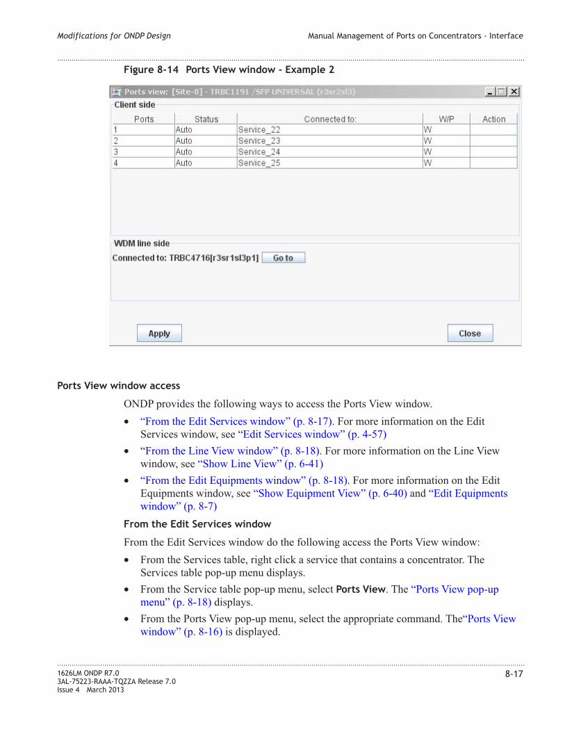
Ports View window access
ONDP provides the following ways to access the Ports View window.
• “From the Edit Services window” (p. 8-17). For more information on the Edit
Services window, see “Edit Services window” (p. 4-57)
• “From the Line View window” (p. 8-18). For more information on the Line View
window, see “Show Line View” (p. 6-41)
• “From the Edit Equipments window” (p. 8-18). For more information on the Edit
Equipments window, see “Show Equipment View” (p. 6-40) and “Edit Equipments
window” (p. 8-7)
From the Edit Services window
From the Edit Services window do the following access the Ports View window:
• From the Services table, right click a service that contains a concentrator. The
Services table pop-up menu displays.
• From the Service table pop-up menu, select Ports View. The “Ports View pop-up
menu” (p. 8-18) displays.
• From the Ports View pop-up menu, select the appropriate command. The“Ports View
window” (p. 8-16) is displayed.
Figure 8-14 Ports View window - Example 2
Modifications for ONDP Design Manual Management of Ports on Concentrators - Interface
....................................................................................................................................................................................................................................
....................................................................................................................................................................................................................................
1626LM ONDP R7.0
3AL-75223-RAAA-TQZZA Release 7.0
Issue 4 March 2013
8-17

From the Line View window
From the Line View window do the following access the Ports View window.
• From the Line View window, double-click the desired channel for which to display
the Ports View window. The rest of the window will be greyed out and the Open
command on the Main menu will become active.
• From the Line View main menu, select Open.
• From the Open menu, select either Source Port Window to open the Ports View
window for the source port, or Destin Port Window to open the Port View window
for the destination port. The “Ports View window” (p. 8-16) is displayed if the
channel transmission is made through a concentrator.
From the Edit Equipments window
From the Edit Equipments window do the following access the Ports View window
• In the Main panel, right-click a concentrator equipment for wich the Ports View
window will be displayed. The Equipment menu is displayed
• From the Equipment menu, click Show Port Window. The “Ports View window”
(p. 8-16) is displayed.
Ports View pop-up menu
The Ports View pop-up menu contains commands that open the Ports View window for
the selected concentrator.
The following table describes the commands in the Ports View pop-up menu.
Table 8-8 Ports View pop-up menu
Command Description
Working [W] Source Ports View Opens the Ports View window to manually
manage working source ports for the selected
service
Working [W] Destination Ports View Opens the Ports View window to manually
manage working destination ports for the
selected service
Figure 8-15 Ports View pop-up menu
Modifications for ONDP Design Manual Management of Ports on Concentrators - Interface
....................................................................................................................................................................................................................................
....................................................................................................................................................................................................................................
8-18 1626LM ONDP R7.0
3AL-75223-RAAA-TQZZA Release 7.0
Issue 4 March 2013

Table 8-8 Ports View pop-up menu (continued)
Command Description
Protecting [P] Source Ports View Opens the Ports View window to manually
manage protecting source ports for the
selected service
Protecting [P] Destination Ports View Opens the Ports View window to manually
manage protecting destination ports for the
selected service
Ports View window
The following table describes the fields in the Ports View window.
Table 8-9 Ports View window field descriptions
Client side
Field
Client side
Description
Ports The port number on the concentrator. To
manage the port connection, click the Ports
field and select the new port from the
displayed list.
Status The status of the port. Default value is Auto.
For more information, see “Concentrator ports
Status” (p. 8-15)
Connected to: Information about the service or board to
which the port is connected.
W/P Identifies the service as working (W) or
protecting (P)
Action In the case of a cascade of concentrators,
(2.5G->10G->40G): TRBC1191 (client side)
connected to TRBC4_16, (WDM line side),
the Go to command is displayed in this
column. Click the Go to command to toggle
between the Ports View client side and line
side Ports View windows
WDM line side
Field
WDM line side
Description
Modifications for ONDP Design Manual Management of Ports on Concentrators - Interface
....................................................................................................................................................................................................................................
....................................................................................................................................................................................................................................
1626LM ONDP R7.0
3AL-75223-RAAA-TQZZA Release 7.0
Issue 4 March 2013
8-19

Table 8-9 Ports View window field descriptions (continued)
Client side
Field
Client side
Description
Connected to: Information about the board to which the port
is connected.
In the case of a cascade of concentrators,
(2.5G->10G->40G): TRBC1191 (client side)
connected to TRBC4_16, (WDM line side),
the Go to button is displayed in this field.
Click the Go to button to toggle between the
Ports View line side and client side Ports View
windows
The Connected to: field contains the following information:
• For each tributary the direct next downstream connection (towards the client side) for
each port is displayed as follows:
If the board is directly linked to
– a service - the service label is displayed (*)
– another board (except OCPU) - the board type and location is displayed (**)
– an OCPU - the OCPU type and location are displayed followed by a semi colon ;
and the direct next downstream connection as described in (*) and (**) above
• The direct next upstream connection (towards the WDM line side) for each port is
displayed as follows:
If the board is a
– tributary - the board type and the board location +port is displayed
– OCPU - the OCPU type and location is displayed. Also the direct next upstream
connection board, type and board location +port for the Working and Protecting
paths is displayed
Modifications for ONDP Design Manual Management of Ports on Concentrators - Interface
....................................................................................................................................................................................................................................
....................................................................................................................................................................................................................................
8-20 1626LM ONDP R7.0
3AL-75223-RAAA-TQZZA Release 7.0
Issue 4 March 2013

9 9Map Management
Overview
Purpose
This chapter provides information on how to generate and calibrate background maps for
the ONDP application.
Contents
Map Generation 9-2
Launch the Map Generation Application 9-7
Generate a Background Map 9-8
...................................................................................................................................................................................................................................
1626LM ONDP R7.0
3AL-75223-RAAA-TQZZA Release 7.0
Issue 4 March 2013
9-1

Map Generation
Map Generation overview
ONDP provides the Map Generation application, which enables users to generate multiple
calibration maps used in network design. After generation, the maps are displayed as
background maps, which are selected from the Choose the default background map
field at the start of the ONDP application, or at the start of a new network design.
Note: Initially, ONDP includes a default background map of Europe, referred to as
Europe [Relief] and a blank map, referred to as Empty Map.
Map Generation command file
The command file which runs the Map Generation application is stored in the ONDP root
directory, in the Programs folder. The command to run this file is:
ondp_mapbuilder.exe
The path to this file is:
Program Files/Alcatel-Lucent/ONDP X.X (where X.X is the release number).
Map source file
The user background maps are generated by the ONDP Map Generation application from
any source map file, as long as the file is in GIF, JPEG or PNG format, and is stored on
the user's PC.
Map generation and calibration process
Background maps are generated and calibrated through a five step process, presented in a
series of five Map Calibration windows. The steps are described in the following sections.
For detailed task information on map generation and calibration, see “Generate a
Background Map” (p. 9-8).
At the end of this process a new background map with the specified name is stored in the
ONDPMapDir folder. When creating a network design, generated maps can be selected and
displayed on the Topology Map as part of the network design.
Map Calibration - Step 1 window
The Map Calibration - Step 1 window creates the background map name and identifies
the user's source map file from which the background map will be generated.
Map Management Map Generation
....................................................................................................................................................................................................................................
....................................................................................................................................................................................................................................
9-2 1626LM ONDP R7.0
3AL-75223-RAAA-TQZZA Release 7.0
Issue 4 March 2013

Map Calibration - Step 2 window
The Map Calibration - Step 2 window displays the user's source map file. From this
display, select the area of the source map which will be generated as the new background
map.
Figure 9-1 Map Calibration - Step 1 window
Figure 9-2 Map Calibration - Step 2 window
Map Management Map Generation
....................................................................................................................................................................................................................................
....................................................................................................................................................................................................................................
1626LM ONDP R7.0
3AL-75223-RAAA-TQZZA Release 7.0
Issue 4 March 2013
9-3

Map Calibration - Step 3 window
The Map Calibration - Step 3 window specifies a site on the north west part of the map.
This selects the pixels on the map where the first site is located. In this example, Paris is
the site specified.
Map Calibration - Step 4 window
The Map Calibration - Step 4 window specifies a site in the south east direction of the site
specified in the previous window. This selects the pixels on the map where the second site
is located. The further the sites are from each other, a better calibration is possible. In this
example, Lyon is specified.
Figure 9-3 Map Calibration - Step 3 window
Map Management Map Generation
....................................................................................................................................................................................................................................
....................................................................................................................................................................................................................................
9-4 1626LM ONDP R7.0
3AL-75223-RAAA-TQZZA Release 7.0
Issue 4 March 2013

Map Calibration - Step 5 window
The Map Calibration - Step 5 window enables the user to enter names for the sites
selected in the previous calibration steps, and to indicate the Geographic Information
System (GIS) (latitude/longitude) coordinates of the sites for map calibration. This step
associates the pixels selected in Step 3 and Step 4 with the GIS information, to allow the
system to calibrate the map. Note: Accurate GIS information is essential to proper
calibration of the map. If inaccurate GIS information is used, the calibrated sites may not
be within the map area.
Map Management Map Generation
....................................................................................................................................................................................................................................
....................................................................................................................................................................................................................................
1626LM ONDP R7.0
3AL-75223-RAAA-TQZZA Release 7.0
Issue 4 March 2013
9-5

Figure 9-4 Map Calibration - Step 5 window
Map Management Map Generation
....................................................................................................................................................................................................................................
....................................................................................................................................................................................................................................
9-6 1626LM ONDP R7.0
3AL-75223-RAAA-TQZZA Release 7.0
Issue 4 March 2013

Launch the Map Generation Application
When to use
Use this task to launch the Map Generation application on the PC.
Related information
See the following topic in this document:
• “Map Generation” (p. 9-2)
Before you begin
Before you begin this task, a source map file in GIF, JPEG or PNG format must be stored
on the user's PC.
Task
...................................................................................................................................................................................................
1 Locate the executable application file ondp_mapbuilder.exe using this path:
C:/Program files/Alcatel-Lucent/ONDP X.X (where X.X is the release number).
...................................................................................................................................................................................................
2 Double click on the ondp_mapbuilder.exe executable file.
Result: The application is launched, and the Map Calibration - Step 1 window is
displayed.
Map Management Launch the Map Generation Application
....................................................................................................................................................................................................................................
....................................................................................................................................................................................................................................
1626LM ONDP R7.0
3AL-75223-RAAA-TQZZA Release 7.0
Issue 4 March 2013
9-7
E N D O F S T E P S...................................................................................................................................................................................................

Generate a Background Map
When to use
Use this task to generate and calibrate a new background map to use in network design.
Related information
See the following topic in this document:
• “Map Generation” (p. 9-2)
Before you begin
Before you begin this task, a source map file in GIF, JPEG or PNG format must be stored
on the user's PC.
Task
Use this task to generate and calibrate a new background map.
...................................................................................................................................................................................................
1 Follow the steps in the “Launch the Map Generation Application” (p. 9-7) to start the
Map Generation application.
Result: The Map Calibration - Step 1 window is displayed.
...................................................................................................................................................................................................
2 Do the following:
• In the Enter the map name field, enter the name of the new map.
• In the Select map image field, click the File icon to open the Load background image
window. Use the file hierarchy to explore to the map source file. Select the map
source file and click Open.
Result: The map source file is selected.
...................................................................................................................................................................................................
3 Click the Next button.
Result: The Map Calibration Informations window displays the message
Select the area you want to keep on the map, and press Next
...................................................................................................................................................................................................
4 Click the OK button.
Map Management Generate a Background Map
....................................................................................................................................................................................................................................
....................................................................................................................................................................................................................................
9-8 1626LM ONDP R7.0
3AL-75223-RAAA-TQZZA Release 7.0
Issue 4 March 2013

Result: The map source file is displayed in the Map Calibration - Step 2 window.
...................................................................................................................................................................................................
5 In the Map Calibration - Step 2 window, select the area of the displayed map source file
to be used in the new background map using any of the following tools:
Tool Description
Zoom in icon Click the icon to make the area smaller
Zoom out icon Click the icon to make the area larger
Image Scale Icon Click the icon to bring the map to initial size
Select all map icon Click the icon to select the entire area of the
source map
Graphic box Click and drag on the map to manipulate a
graphics box for the selected area
Result: The area to be generated as the background map is selected.
...................................................................................................................................................................................................
6 Click the Next button.
Result: The Map Calibration Informations window displays the message
Place a site on the map, and press Next
...................................................................................................................................................................................................
7 Click the OK button.
Result: The Map Calibration - Step 3 window is displayed.
...................................................................................................................................................................................................
8 Click on the map where the initial site is located. This selects the pixels on the map where
the initial site is located.
Result: A black dot appears on the selected site.
...................................................................................................................................................................................................
9 Click the Next button.
Result: The Map Calibration Informations window displays the message
Place a second site at the south east of the first site, and
press next. The Further the sites, the better calibration.
...................................................................................................................................................................................................
10 Click the OK button.
Map Management Generate a Background Map
....................................................................................................................................................................................................................................
....................................................................................................................................................................................................................................
1626LM ONDP R7.0
3AL-75223-RAAA-TQZZA Release 7.0
Issue 4 March 2013
9-9
Result: The Map Calibration - Step 4 window is displayed.
...................................................................................................................................................................................................
11 Click on the map where the second site is located. This selects the pixels on the map
where the second site is located.
Result: A black dot appears on the second selected site.
...................................................................................................................................................................................................
12 Click the Next button.
Result: The following two results occur:
• A new background map is created and saved in the C:/Program Files/ONDP
X.X/ONDPMapDir folder (where X.X is the release number). The name of the file
is the name specified in the Map Calibration - Step 1 window. The file is saved in
the PNG format.
• The Skip Calibration window displays the message
Do you want to skip the calibration phase?
...................................................................................................................................................................................................
13 Do one of the following:
• If you wish to skip the map calibration phase, click the Yes button.
Result: The application is closed. End of Steps.
• If you wish to continue with the map calibration phase, click the No button.
Result: The Map Calibration - Step 5 window is displayed.
...................................................................................................................................................................................................
14 In the Map Calibration - Step 5 window, do the following:
• In the North West Point Informations section:
– In the Site Name field, enter the first site name specified in the Map Calibration -
Step 3 window
– In the Enter GIS X field, enter the longitude coordinate of the site
– In the Enter GIS Y field, enter the latitude coordinate of the site
• In the South East Point Informations section:
– In the Site Name field, enter the second site name specified in the Map
Calibration - Step 4 window
– In the Enter GIS X field, enter the longitude coordinate of the site
– In the Enter GIS Y field, enter the latitude coordinate of the site
• Click the Next button.
Map Management Generate a Background Map
....................................................................................................................................................................................................................................
....................................................................................................................................................................................................................................
9-10 1626LM ONDP R7.0
3AL-75223-RAAA-TQZZA Release 7.0
Issue 4 March 2013

Result: The message The map calibration end successful is displayed. and
the new background map will be presented in the list of available maps when
beginning a network design. For more information, see “Section 1: Starting the
Design” (p. 4-3).
Map Management Generate a Background Map
....................................................................................................................................................................................................................................
....................................................................................................................................................................................................................................
1626LM ONDP R7.0
3AL-75223-RAAA-TQZZA Release 7.0
Issue 4 March 2013
9-11
E N D O F S T E P S...................................................................................................................................................................................................

Map Management Generate a Background Map
....................................................................................................................................................................................................................................
....................................................................................................................................................................................................................................
9-12 1626LM ONDP R7.0
3AL-75223-RAAA-TQZZA Release 7.0
Issue 4 March 2013

Glossary
...................................................................................................................................................................................................................................
A A/D
Add and Drop
Access Identifier (AID)
A unique identifier used to address equipment slots and ports, as well as facility tributaries, that
are defined for system architecture.
ACO (Alarm Cut-Off)
A push-button switch on the indicator strip that can be used to retire an audible office alarm.
ADM
Add and Drop Multiplex
A high-speed multiplexing function offered by SONET/SDH that allows lower level signals to be
added to or dropped from an optical carrier channel.
AFI
Authority and Format Identifier
AID
See “Access IDentifier”.
AIS
Alarm Indication Signal
A signal sent downstream by an NE to indicate that its incoming signal has failed.
Alarm
External notification or display of failure condition. The indication of a failure towards an
external system interface or from audible or visible indicators.
Alarm Severity
Defines the priority of the alarm message. The method in which alarms are processed depends on
their severity.
ALCT
Automatic Level ConTrol
ALS
Automatic Laser Shutdown
....................................................................................................................................................................................................................................
1626LM ONDP R7.0
3AL-75223-RAAA-TQZZA Release 7.0
Issue 4 March 2013
GL-1

AMS
Alcatel Maintenance Signal. There are two types of AMS: AMSs (for legacy submarine
equipment) and AMSt (for legacy terrestrial equipment)
ANTP
Alcatel Network Time Protocol
APA
Automatic Pre-emphasis Adjustment
APC
Automatic Power Control
APD
Avalanche Photo Detector
A diode that increases its electrical conductivity by a multiplication effect when hit by light. APDs
are used in lightwave receivers because the APDs have a greater sensitivity to weakened light
signals (for example, those which have traveled long distances over fiber).
APE
Automatic Power Equalization
APS
Automatic Protection Switching
A feature that allows a protection or standby entity (for example, optical line or board) to be
automatically selected and reconfigured if an incoming signal or equipment failure occurs.
APSD
Automatic Power ShutDown
APT
Amplifier Power Tuning
AS
Alarm Surveillance
ASAP
Alarm Severity Assignment Profile
ASIC
Application Specific Integrated Circuit
ATTD
ATTendeD (Alarm storing)
...................................................................................................................................................................................................................................
B B&W
Black and White
Glossary
....................................................................................................................................................................................................................................
....................................................................................................................................................................................................................................
GL-2 1626LM ONDP R7.0
3AL-75223-RAAA-TQZZA Release 7.0
Issue 4 March 2013

BDFB
Battery Distribution and Fuse Bay
Bit Error Rate (BER)
BER measures how accurately a bit stream is transmitted through a system. It measures how
many bits are received in error compared to how many are sent. It is the ratio of error bits
received to the total number of bits transmitted.
BMDX
Band Multiplexer DemultipleXer
BOFA
Band Optical Fiber Amplifier
BOL
Beginning of Life
BOM
Bill of Materials
...................................................................................................................................................................................................................................
C CAD
Channel Add-drop Card
Used with automatic power management; allows setpoints for a manual transmission line.
CBR
Constant Bit Rate
CD-ROM
Compact Disk, Read-Only Memory
CDR
Clock and Data Recovery
Ch
Channel
Channel
A communication path or the signal sent over that path.
CID
Card Identifier
CLEI
Common Language Equipment Identification
CLEI codes enable you to clearly and consistently identify and track virtually every type of
telecommunications equipment. In the United States, these codes are assigned by Telecordia and
are 10 bytes long.
Glossary
....................................................................................................................................................................................................................................
....................................................................................................................................................................................................................................
1626LM ONDP R7.0
3AL-75223-RAAA-TQZZA Release 7.0
Issue 4 March 2013
GL-3

CLI
Command Line Interface
Client-AIS
Alarm Indicator Signal (Client side)
CLNP
ConnectionLess Network Protocol
An OSI network layer protocol that allows data to be transmitted without first requiring that a
circuit be established.
CMDX
Channel Multiplexer DemultipleXer
COTDR
Coherent Optical Time Domain Reflectometer
CPE
Customer Premises Equipment
Refers to any type of telephone equipment, for example, answering machines, etc. on customer
premises.
CT
Craft Terminal
The user interface terminal used by craft personnel to communicate with a network element.
...................................................................................................................................................................................................................................
D DAPI
Destination Address Point Identifier
DC_DC
DC/DC Direct Current Converter
DCC
Data Communication Channel - A portion of the SDH/SONET signal that contains alarms,
surveillance, and performance information.
Data Country Code
DCM
Dispersion Compensation Module
Spooled fiber used to control excess dispersion found in certain fiber types at pre- and
post-amplification.
DCN
Data Communication Network
DCNs support communication between NEs and the NMS.
Glossary
....................................................................................................................................................................................................................................
....................................................................................................................................................................................................................................
GL-4 1626LM ONDP R7.0
3AL-75223-RAAA-TQZZA Release 7.0
Issue 4 March 2013

DCU
Dispersion Compensating Unit
See also “DCM”
DDM
Digital Diagnostic Monitoring
DEMUX or DMX
Demultiplexer
A module that separates two or more signals previously combined by compatible multiplexing
equipment.
DHCP (Dynamic Host Configuration Protocol)
A protocol that automates the configuration of computers that use TCP/IP. DHCP allows a DHCP
server to automatically assign an IP address to a computer's TCP/IP stack software. The number is
taken from a defined range of numbers for a given network.
DSP
Domain Specific Part or Digital Signal Processing
DTMF
Dual Tone Modulation Frequency
DTV
Decision Threshold Voltage
DV
Digital Video
DWDM
Dense Wavelength Division Multiplexing
A multiplexing technique that uses close spectral spacing of individual optical carrier wavelengths
to reduce the total number of fibers needed to provide a given amount of information-carrying
capacity. The technique takes advantage of desirable transmission characteristics (for example,
minimum dispersion or attenuation) within a given fiber.
...................................................................................................................................................................................................................................
E EAM
Electro Absorption Modulator
EC
Equipment Controller card
ECC
Embedded Channel Communication
ECID
Enhanced Card IDentifier
Glossary
....................................................................................................................................................................................................................................
....................................................................................................................................................................................................................................
1626LM ONDP R7.0
3AL-75223-RAAA-TQZZA Release 7.0
Issue 4 March 2013
GL-5

ECMA
European Computer Manufacturers Association (Former standardizing information and
communication system organization)
ECT
Equipment Craft Terminal
EDFA
Erbium Doped Fiber Amplifier
A type of amplifier with a short length of fiber that been doped with erbium and spliced into the
operating single-mode fiber (SMF). A three-port wavelength division multiplexer (WDM) is used,
with one incoming port connected to the operating fiber carrying the primary signal in the 1550
nm window, one incoming port attached to a pump laser operating at 980 nm or 1480 nm, and one
outgoing port connected to the operating fiber.
EEPROM
Electrically Erasable Programmable Read Only Memory
A type of non-volatile memory often used to store inventory data.
EMC
Electromagnetic Compatibility
The ability of a device or system to function without error in its intended electromagnetic
environment.
EMI
Electromagnetic Interference
High-energy, electrically induced magnetic fields that cause data corruption in cables passing
through the fields.
EML
Equipment Management Layer
Electroabsorption Modulated Laser - When laser is modulated using a Mach-Zehnder modulator.
EMPM
External Multi-Pump Module
EOL
End Of Life
Defines the status or values at the end of the guaranteed lifetime of a component. EOL is reached
when the wear-out failure rate dominates the component failure rate.
EOW
Engineering Order Wire
EPT
Engineering and Planning Tool
Glossary
....................................................................................................................................................................................................................................
....................................................................................................................................................................................................................................
GL-6 1626LM ONDP R7.0
3AL-75223-RAAA-TQZZA Release 7.0
Issue 4 March 2013

ESC
Equipment and Shelf Controller
ESCT
Equipment and Shelf ConTroller
ESD
Electrostatic Discharge
Static electrical energy potentially harmful to boards and humans.
ESTI
European Telecommunication Standard Institute
Located in Sophia-Antipolis, France, ETSI is the European counterpart of ANSI. Its task is to
pave the way for telecommunications integration in the European community as part of the single
European market program. It establishes telecommunication standards for the European
community.
EXP
Expansion
...................................................................................................................................................................................................................................
F FC
Fiber Channel
FDI
Forward Defect Indication
An automatic and fully distributed capability which indicated a failure in a server networking
layer (e.g. Physical Layer). When used with other mechanisms such as CV (Connectivity
Verification), it can indicate defects such as misbranding of Label Switched Paths (LSPs) and
errors in swapping LSP labels.
FEC
Forward Error Correction
A technique used for error detection and correction in which the transmitting host computer
includes some number of redundant bits in the payload (data field) of a block or frame of data.
The receiving device uses those bits to detect, isolate, and correct any errors created during
transmission. FEC avoids having to retransmit information which incurred errors in network
transit.
FIT
Failure In Time
A unit of failure rate in reliability analysis. One FIT is equivalent to one failure per one billion
operating hours.
FPGA
Field Programmable Gate Array
A user-configurable logic device that holds user-defined logic constructs and interconnects in the
Glossary
....................................................................................................................................................................................................................................
....................................................................................................................................................................................................................................
1626LM ONDP R7.0
3AL-75223-RAAA-TQZZA Release 7.0
Issue 4 March 2013
GL-7

form of a microprocessor. Examples include EEPROM and FLASH.
FTP (File Transfer Protocol)
A protocol used for exchanging files over the Internet. FTP uses the Internet's TCP/IP protocols to
enable data transfer. FTP is most commonly used to download/upload a file to/from a server using
the Internet.
...................................................................................................................................................................................................................................
G Gain
The increase in power and magnitude of a signal.
GbE
Gigabit Ethernet
A transmission technology based on the Ethernet frame format and protocol used in local area
networks (LANs) that provides a data rate of one billion bits (one gigabit) per second. Gigabit
Ethernet is defined in the IEEE 802.3 standard and is currently used as the backbone in many
enterprise networks.
GCC
Generic Communication Channel
GE_FC
Gigabit Ethernet Fiber Channel
GMPLS
Generalized Multi-Protocol Label Switching
GMPLS is an extension of the MPLS protocol used in data networks. MPLS is packet based
technology that combines the advantages of packet and circuit based networks. GMPLS is the
extension of this concept to cope additionally with SDH and OTH based transmission networks.
Therefore, GMPLS includes, in addition to packet switching capable devices (IP/MPLS), frame
(Ethernet), cell (ATM), timeslot (SONET/SDH, OTH), wavelength (optical channels) and spatial
(fiber) switching capable devices.
GMRE
Generalized Multi-Protocol Label Switching (GMPLS) Routing Engine
GR
Guaranteed Restoration services
GUI
Graphical User Interface
A program interface that takes advantage of the computer's graphics capabilities to make the
program easier to use.
Glossary
....................................................................................................................................................................................................................................
....................................................................................................................................................................................................................................
GL-8 1626LM ONDP R7.0
3AL-75223-RAAA-TQZZA Release 7.0
Issue 4 March 2013

...................................................................................................................................................................................................................................
H HDLC
High Level Data Link Control
An ITU-TSS link layer protocol standard for point-to-point and multipoint communication. In
HDLC, the control information is always placed in the same position, and it uses specified bit
patterns very different from the data, thus reducing the likelihood of confusion.
HK
HouseKeeping
HW
Hardware
HWF
Hardware Failure
...................................................................................................................................................................................................................................
I I/F
Interface
I/O
Input/Output
IDEG
Input DEGraded
IDI
Initial Domain Identifier
IEC
International Electrotechnical Commission
The international standards and conformity assessment body for all fields of electrotechnology,
including electricity and electronics.
ILM
Integrated Laser Modulator
ILOS
Input Loss Of Signal
IND
INDeterminate
IP
Internet Protocol
A standard protocol designed for use in interconnected systems of packet-switched computer
communication networks. The Internet Protocol provides for transmitting blocks of data called
Glossary
....................................................................................................................................................................................................................................
....................................................................................................................................................................................................................................
1626LM ONDP R7.0
3AL-75223-RAAA-TQZZA Release 7.0
Issue 4 March 2013
GL-9

datagrams from sources to destinations, where sources and destinations are hosts identified by
fixed-length addresses. The Internet Protocol also provides for fragmentation and reassembly of
long datagrams, if necessary, for transmission through small-packet networks.
IS-IS
Intermediate System-to-Intermediate System
ISO
International Standard Organization
A United Nations agency concerned with international standardization in a broad range of
industrial and technical fields.
ISPB
Intra Shelf Parallel Bus
ISSB
Intra Shelf Serial Bus
ITU
International Telecommunication Union
A United Nations telecommunications agency established to provide standardized
communications procedures and practices including frequency allocation and radio regulations on
a worldwide basis.
ITU-T
International Telecommunications Union — Telecommunication standardization sector. Formerly
known as CCITT: Comité Consultatif International Télégrafique & Téléphonique; International
Telegraph and Telephone Consultative Committee.
...................................................................................................................................................................................................................................
L LAN
Local Area Network
1. A communication link between two or more points within a small geographic area, such as
between buildings. 2. A data network that has a size of normally up to 10 km. Important LANs are
Ethernet, Token Ring, Token Bus, and FDDI.
LAPD
Link Access Protocol on D-channel
A special protocol of the OSI Data Link Layer that provides the functional and procedural means
to establish, maintain, and release data link connections for NEs. For NE-NE communications
over the DCC, Layer 2 services are provided by LAPD.
LED
Light Emitting Diode
A diode made out of semiconductor material like Gallium-Arsenide that translates electrical
current into light. An LED is a semiconductor that emits incoherent light to show failure or
service state of a board. It is also used to show the alarm and status condition of the system.
Glossary
....................................................................................................................................................................................................................................
....................................................................................................................................................................................................................................
GL-10 1626LM ONDP R7.0
3AL-75223-RAAA-TQZZA Release 7.0
Issue 4 March 2013

LH
Long Haul
A 10 Gbps application for transmission of 128 channels, giving a capacity of 1.28 Tbps and a
reach of up to 2000 km. Payload (per channel) can be one OC-192/STM-64 or four
OC-48/STM-16 signals.
LM
Light Manager or Line Manager
LOF
Loss of Frame
LOF is detected when the OOF (out-of-frame) anomaly persists for a certain time.
LOFA
Line Optical Fiber Amplifier
Loopback
Type of diagnostic test used to compare an original transmitted signal with the resulting received
signal. A loopback is established when the received optical or electrical external transmission
signal is sent from a port or tributary unit directly back toward the output.
LOS
Loss of Signal
A condition where the optical input power falls below a prescribed threshold.
LR
Line Repeater
LSD
Laser ShutDown
LSP
Label Switched Path
LT
Line Terminal
...................................................................................................................................................................................................................................
M MAC
Medium Access Control
MAC Address
A computer's unique hardware number. The MAC address is used by the media access control
sublayer of the data link layer of telecommunications protocols and identifies each node in a
network.
Glossary
....................................................................................................................................................................................................................................
....................................................................................................................................................................................................................................
1626LM ONDP R7.0
3AL-75223-RAAA-TQZZA Release 7.0
Issue 4 March 2013
GL-11

MIB
Management Information Base
A formal description of a set of network objects that can be managed using the Simple Network
Management Protocol (SNMP). The information is represented in a tree format.
MMF or MM
Multi Mode Fiber
MPLS
MuliProtocol Label Switching
MS
Multiplex Section
MU/SPC
A flat-polished MU type optical connector.
Multiplexing
The process of combining multiple signals into a larger signal at the transmitter by a multiplexer.
The large signal is then split into the original smaller signals at the receiver by a demultiplexer.
MUX/Multiplexer
A device (board) that combines two or more transmission signals into a combined signal on a
shared medium.
MZ
Mach-Zehnder
...................................................................................................................................................................................................................................
N NCTL (Network Element Controller) Board
The NCTL provides control and user interfaces at the NE level.
NDC
Negative Dispersion Chromatic
NDSF
Non Dispersion Shifted Fiber
NDSF
Non Dispersion Shifted Fiber
NE
Network Element
The basic building block of a telecommunications equipment within a telecommunication
network that meets SONET/SDH standards. Typical internal attributes of a network element
include: one or more high- and low-speed transmission ports, built-in intelligence,
synchronization and timing capability, and access interfaces for use by technicians and/or
operation systems. In addition, a network element may be a time slot interchanger.
Glossary
....................................................................................................................................................................................................................................
....................................................................................................................................................................................................................................
GL-12 1626LM ONDP R7.0
3AL-75223-RAAA-TQZZA Release 7.0
Issue 4 March 2013

NES
Network Element Synthesis
NML
Network Management Layer
NMS
Network Management System
Provides an efficient means of managing the equipment and services within a network, including
creating new services, diagnosing faults, and planning for growth. It has interfaces to external
systems to allow functions such as billing, service orders, and service level agreement (SLA)
management.
NNI
Network-to-Network Interface
NRZ
Non-Return to Zero
A binary encoding in which ones and zeros are represented by opposite and alternating high and
low voltages and where there is no return to a zero voltage between encoded bits.
NSAP
Network Service Access Point (used in the OSI network layer).
An automatically assigned number that uniquely identifies a Network Element for the purposes of
routing DCC messages.
NTP
Network Time Protocol
An easy, accurate, and automatic method of getting and synchronizing date/time.
NURG
Not URGent
NZ–DSF
NonZero Dispersion Shifted Fiber
...................................................................................................................................................................................................................................
O OAC
Optical Amplifier Card
OADC
Optical Add & Drop Coupler
OADM
Optical Add & Drop Multiplexer
A network element which allows a WDM transmission link to add or drop optical signals, without
converting the photonic stream into an electrical signal. Insertion and extraction are done using
Glossary
....................................................................................................................................................................................................................................
....................................................................................................................................................................................................................................
1626LM ONDP R7.0
3AL-75223-RAAA-TQZZA Release 7.0
Issue 4 March 2013
GL-13

optical fibers and demultiplexers. An OADM can be either non-reconfigurable or reconfigurable.
In the latter case, optical switches need to be used.
OBC
On Board Controller
OCH
Optical CHannel
OCHA
Optical CHannel Adaptation
OCNC
Optical CoNnectivity Coupler
OCPU
Optical Channel Protection Unit
OCWR
Optical Continuous Wave Reflectometer
An instrument used to characterize a fiber optic link where an unmodulated signal is transmitted
through the link, and the resulting light scattered and reflected back to the input is measured.
ODU
Optical Channel Data Unit
OGPI
Optical Generic Physical Interface
OH
OverHead
OLOS
Output Loss Of Signal
OMDX
Optical Multiplexer DemultipleXer
OMS
Optical Multiplex Section or Optical Management System
OMSA
Optical Multiplex Section Adaptation
OMSP
Optical Multiplex Section Protection
OND or ONDP
Optical Network Design Platform
Glossary
....................................................................................................................................................................................................................................
....................................................................................................................................................................................................................................
GL-14 1626LM ONDP R7.0
3AL-75223-RAAA-TQZZA Release 7.0
Issue 4 March 2013

OPC
Optical Protection Card
Optical Channel
An optical wavelength band for WDM optical communications.
OS
Operation System
OSC
Optical Supervisory Channel
The embedded overhead communications channel originating from 1626 NEs used for end-to-end
communications and maintenance. The OSC carries alarm, control, and status information
between network elements in a synchronous network.
OSCU
Optical Supervisory Channel Unit
OSI
Open System Interconnection reference model
A seven-layer model that pertains to the logical structure for communications networks
standardized by the International Organization for Standardization (ISO). Adherence to the
standard enables any OSI-compliant system to communicate with any other OSI-compliant
system.
OSMC
Optical Spectrum Monitoring Control
OSNCP
Optical SubNetwork Connection Protection
OSNR
Optical Signal Noise Ratio
The ratio between the optical power of the data signal and the power of the optical noise signal.
OSPI
Optical Generic Physical Interface
OTM
Optical Transport Module, G.709
Provides bi-directional electrical/optical signal conversions in point-to-point applications. Optical
signals propagate at two wavelengths over a single fiber.
OTN
Optical Transport Network
Network used to transport user signals via ITU compliant wavelengths. The OTN is composed of
the OCH and OTS layers.
Glossary
....................................................................................................................................................................................................................................
....................................................................................................................................................................................................................................
1626LM ONDP R7.0
3AL-75223-RAAA-TQZZA Release 7.0
Issue 4 March 2013
GL-15

OTS
Optical Transmission Section
The lower layer of the OTN that provides physical transport. The OTS layer is terminated on an
OTS terminating equipment.
OTU
Optical channel Transport Unit
...................................................................................................................................................................................................................................
P PDH
Plesiochronous Digital Hierarchy
PDL
Polarization Dependent Loss
Loss of optical power that occurs during the polarization process. Polarized light waves are light
waves in which the vibrations occur in a single plane. The process of transforming unpolarized
light into polarized light is known as polarization (the orientation of the electric and magnetic
field vectors of a propagating electro-magnetic wave).
PDP
Power Distribution Panel
PDU
Power Distribution Unit
PDU
Protocol Data Unit
A device used for the information exchange between equal protocol layers.
PGE
Programmable Gain Equalization
PIN
Positive - Intrinsic - Negative
PM
Performance Monitoring
Measures the quality of service and identifies degrading or marginally operating systems (before
an alarm would be generated).
PMA
Physical Medium Attachment
PMD
Physical Medium Dependent
Glossary
....................................................................................................................................................................................................................................
....................................................................................................................................................................................................................................
GL-16 1626LM ONDP R7.0
3AL-75223-RAAA-TQZZA Release 7.0
Issue 4 March 2013

PMD
Polarization Mode Dispersion
An inherent property of all optical media. It is caused by the difference in the propagation
velocities of light in the orthogonal principal polarization states of the transmission medium. The
net effect is that if an optical pulse contains both polarization components, then the different
polarization components travel at different speeds and arrive at different times, smearing the
received optical signal.
PMDC
Polarization Mode Dispersion Compensator
PPP
Point-to Point Protocol
An Internet Standard protocol. It establishes a link between two peer machines and maintains that
link by communicating through the hardware layer to the PPP layer on a peer system.
PRC
Protection and Restoration Combined services
PSUP
Power SUPply
PVID
Port Virtual IDentifier
...................................................................................................................................................................................................................................
Q QECC
Interface with Q protocol for Embedded Control Channel
QoS
Quality of Service
A set of performance parameters that characterize the transmission quality over a given virtual
connection.
...................................................................................................................................................................................................................................
R R-OADM
Reconfigurable Optical Add & Drop Multiplexer
An optical network element with a configuration that can be changed remotely. The main benefit
of this feature is that it reduces Operating Expenditures (OPEX) when operating a network.
RA
Remote Alarm
RAM
Random Access Memory
Glossary
....................................................................................................................................................................................................................................
....................................................................................................................................................................................................................................
1626LM ONDP R7.0
3AL-75223-RAAA-TQZZA Release 7.0
Issue 4 March 2013
GL-17

RDI
Remote Defect Indicator
RECT
REmote Craft Terminal
RGMII
Reduced Gigabit Media Independent Interface
RI
Remote Inventory
RPO
Receiver Parameter Optimization
RS
Regenerator Section
RS-AIS
Regenerator Section - Alarm Indicator Signal
RS-AIS is a proprietary Alcatel-Lucent Management Signal, defined as an SDH RS frame, with
all ones except Frame Alignment Word and B1 parity.
RSOH
Regenerator Section OverHead
RUM
Replaceable Unit Missing
RUP
Replaceable Unit Problem
RUTM
Replaceable Unit Type Mismatch
RWA
Routing and Wavalength Allocation
The path and wavelength allocated to a service.
Rx
Receiver or Receive
RZ
Return–to–Zero
...................................................................................................................................................................................................................................
S SAPI
Source Address Point Identifier
Glossary
....................................................................................................................................................................................................................................
....................................................................................................................................................................................................................................
GL-18 1626LM ONDP R7.0
3AL-75223-RAAA-TQZZA Release 7.0
Issue 4 March 2013

SB
Short Band
SBR
Source Based Restoration services
SBS
Stimulated Brillouin Scattering
SC
Shelf Controller
SC/APC
An angle-polished SC type optical connector.
SCP
Serial Communication Problem
SD
ShutDown
SDH
Synchronous Digital Hierarchy
A set of fiber-optics-based standards planned for use with SONET and ATM in Europe,
standardized by the ITU-T. Some of the SDH and SONET standards are identical.
SFP
Small Form Factor Pluggable
An optical modular, hot-pluggable transceiver (compatible with IEE-802.3x) designed for use
with small form factor (SFP) connectors, offering high speed and physical compactness.
SLA
Service-Level Agreement
SLTE
Submarine Line Terminating Equipment
SMF or SM
Single Mode Fiber
A type of fiber which is very small in diameter that allows the light to be reflected in a single way
along the lightguide such that there is coherence in the arrival of the light signal.
SMS
Submarine Management System
SMSR
Side Mode Suppression Ratio
Glossary
....................................................................................................................................................................................................................................
....................................................................................................................................................................................................................................
1626LM ONDP R7.0
3AL-75223-RAAA-TQZZA Release 7.0
Issue 4 March 2013
GL-19

SNCP
SubNetwork Connection Protection
SNMP
Simple Network Management Protocol
A standard protocol for the management of entities in an IP local area network (LAN). The
protocol used to transfer information between the network elements and the element management
system (EMS).
SPI
Serial Peripheral Interface
SPLM
Smart Photonic Layer Manager
SPV
SuPerVision
SRG
Shared Risk Group
SSF
Server Signal Failure
SUPVY
Supervisory Channels
Support the following communications: node-to-node, interworking, client LAN, and orderwire
communication.
...................................................................................................................................................................................................................................
T TCA
Threshold Crossing Alert
A condition set when a counter exceeds a user-selected high or low threshold. A TCA does not
generate an alarm but is available on demand through the CIT.
TCP
Transmission Control Protocol
A protocol used with the Internet Protocol to send data in the form of message units between
computers over the Internet. While IP handles the actual delivery of the data, TCP keeps track of
the individual units of data (called packets) that a message is divided into for efficient routing
through the Internet.
TCP/IP
Transmission Control Protocol/Internet Protocol
A suite of several networking protocols developed for the Internet that provides communication
across interconnected networks, between computers with diverse hardware architectures, and
various operating systems. Some examples are FTP, SMTP, and SNMP.
Glossary
....................................................................................................................................................................................................................................
....................................................................................................................................................................................................................................
GL-20 1626LM ONDP R7.0
3AL-75223-RAAA-TQZZA Release 7.0
Issue 4 March 2013

TDF
Total Dropped Frames
TDM
Time Division Multiplexing
A technique for transmitting a number of separate data, voice, and/or video signals simultaneously
over one communication medium by interleaving a portion of each signal one after another.
TDMX
Tunable DeMultiplexer
TIM
Trace Identifier Mismatch
TimActDis
TIM consequent Actions Disabled
TL1
Transaction Language 1
A machine-to-machine communications language that is a subset of ITU's human-machine
language. TL1 messages are expressed as ASCII strings. The messages and syntax are defined by
Telecordia.
TMN
Telecommunication Management Network
A network that interfaces with a telecommunications network at several points to receive
information from, and to control the operation of, the telecommunications network.
TP
Termination Point
TPD
TransPonDer
TR-OADM
Tunable and Reconfigurable Optical Add & Drop Multiplexer
TRBC
TRIButary Concentrator
TRBD
TRIButary Direct
TRCF
Total Received Correct Frame
TRCO
Total Received Correct Octet
Glossary
....................................................................................................................................................................................................................................
....................................................................................................................................................................................................................................
1626LM ONDP R7.0
3AL-75223-RAAA-TQZZA Release 7.0
Issue 4 March 2013
GL-21

TRSEF
Total Received Service Errored Frames
TRU
Top Rack Unit
TTF
Total Transmitted Frames
TTO
Total Transmitted Octets
TTP
Trail Termination Point
Tx
Transmitter or Transmit
...................................................................................................................................................................................................................................
U UAS
Unavailable Seconds
In performance monitoring, the count of seconds in which a signal is declared failed or in which
ten consecutively severely errored seconds (SES) occurred, until the time when ten consecutive
non-SES occur.
UDC
User Data Channel
UEP
Unequipped Equipment Present
UIC
User Interface Card
ULH
Ultra Long Haul
UNI
User-to-Network Interface
UR
UnRepeatered Systems
URG
URGent
USIB
USer Interface Board
Glossary
....................................................................................................................................................................................................................................
....................................................................................................................................................................................................................................
GL-22 1626LM ONDP R7.0
3AL-75223-RAAA-TQZZA Release 7.0
Issue 4 March 2013

USM
User Service Manager
...................................................................................................................................................................................................................................
V VCAT
Virtual Concatenation
Defines an inverse multiplexing procedure whereby the contiguous bandwidth is broken into
individual Virtual Containers (VC) at the source transmitter and logically represented in a Virtual
Concatenation Group (VCG). VCG members are transported as individual VCs across the
SONET/SDH network and recombined at the destination VCG receiver. While contiguous
concatenation requires concatenation functionality at each network element, virtual concatenation
does not.
VHM
Virtual Hardware Machine
VLAN
Virtual Local Area Network
A subset of a LAN. A VLAN is created by putting VLAN IDs in packets that indicate membership
to a VLAN of that ID. A Local Area Network (LAN) can have multiple VLANs within it, up to
the number of IDs available. Members (ports) of different VLANs do not see the traffic of
VLANs of which they are not members. A port may be a member of many VLANs.
VLH
Very Long Haul
VOA
Variable Optical Attenuation, Variable Optical Attenuator, or Variable Optical Amplifier
A device that corrects the signal strength differences that occur in the transmission line.
VSR
Very Short Reach
A SONET/SDH interface that provides a low-cost interconnection solution of less than 300
meters between routers, switches, and DWDM systems.
...................................................................................................................................................................................................................................
W WAN
Wide Area Network
A communication network that uses common-carrier provided lines and covers an extended
geographical area.
Wavelength
The distance between points of corresponding phase of two consecutive cycles of a wave,
typically measured in nanometers (nm). The wavelength is related to the propagation velocity and
the frequency. (Also called lambda).
Glossary
....................................................................................................................................................................................................................................
....................................................................................................................................................................................................................................
1626LM ONDP R7.0
3AL-75223-RAAA-TQZZA Release 7.0
Issue 4 March 2013
GL-23

WB
Wavelength Blocker
WDM
Wavelength Division Multiplexing
WDM merges optical traffic onto one common fiber, sending several signals through one fiber
with different wavelengths of light. WDM allows flexibility in expanding bandwidth. It reduces
costly mux/demux function, and it reuses existing optical signals.
WIS
Wan Interface Sublayer
WMAN
Wavelength MANager
WSS
Wavelength Selective Switch
...................................................................................................................................................................................................................................
X XFP
10-gigabit eXtended Form Factor Pluggable
A pluggable optical transceiver module that combines transmitter and receiver functions in one
compact, flexible, and low cost package format.
...................................................................................................................................................................................................................................
Z ZIC
Zero Installation Craft interface
An NE-embedded graphical user interface (GUI) application for local operation and maintenance.
Glossary
....................................................................................................................................................................................................................................
....................................................................................................................................................................................................................................
GL-24 1626LM ONDP R7.0
3AL-75223-RAAA-TQZZA Release 7.0
Issue 4 March 2013

Index
A Add Spans to Links, 4-48
Audit, 7-4
................................................................................................
B Bill of Material, 6-37
Bill of Material (multi-step), 6-38
................................................................................................
C Change ILA Site Name, 4-34
Change Service Parameters and Copy to a New Service,
4-82
Change Span Parameters and Copy to a New Span, 4-50,
4-50
Channel properties, 4-118
Close ONDP, 2-14
Computation mode, 7-4
Configurations, 4-17
Constraints, 4-57, 4-74, 4-86, 7-4
Create a Link, 4-46
Create a New Project, 4-9
Create a Relation, 4-78
Create an Optical Subset, 4-97
Create an SRG, 4-109
Create Services, 4-80
Create Sites, 4-24
................................................................................................
D Delete Links and Spans, 4-54
Delete Relations and Services, 4-84
Delete Sites, 4-29
Delete SRGs, 4-111
Design, 4-3
full network, 5-2
Design errors, 5-3, 6-35
Design inputs, 4-4
Design menu, 3-7
Design parameters, 4-115
traffic setting, 4-122
WDM layer, 4-117
Design results, 6-2
Dispersion Map, 6-6
Display menu, 3-4
documents
related, xx
................................................................................................
E Edge tooltip, 3-14
Edit a Failure Scope, 4-112
Edit Failures Scope window, 4-105
Edit Links and Spans, 4-47
Edit menu, 3-3
Edit NE Configuration, 4-26
Edit Relations and Services, 4-79
Edit Services window, 4-57
Edit Site Parameters, 4-28
....................................................................................................................................................................................................................................
1626LM ONDP R7.0
3AL-75223-RAAA-TQZZA Release 7.0
Issue 4 March 2013
IN-1

Edit Spans window, 4-37
Edit Spatial and Spectral Constraints, 4-86
Edit SRGs window, 4-99
Encryption, 4-5
Export BoM, 6-71
Export Design Results Excel Report, 6-45
................................................................................................
F Failure analysis, 7-9
Failures Report, 6-24
Failures Scope, 4-105
Features, 1-2
File menu, 3-2
Functionality, 1-8
................................................................................................
G GMRE Simulator, 3-10
GMRE simulator, 7-9
................................................................................................
H Help menu, 3-10
................................................................................................
I Icons
link, 3-15
site, 3-13
toolbar, 3-11
traffic, 3-15
Identify a Link on the Map, 4-55
Identify a Relation on the Map, 4-85
ILA, 4-31
ILA AGE, 4-31
ILA parameters, 4-32
Include/Exclude Links/Sites in SRGs, 4-110
Incremental design, 4-6
Inputs menu, 3-5
Install ONDP, 2-7
Installation
requirements, 2-2
Installer Welcome window, 2-4
Interface, 1-9
................................................................................................
L Launch ONDP, 2-13
Layer
WDM parameters, 4-117
License key, 2-2
types, 2-2
Links, 4-37
parameters, 4-39
................................................................................................
M Main menu, 3-2, 3-2
Manual network creation, 7-2
Menu
Design, 3-7
Display, 3-4
Edit, 3-3
File, 3-2
Help, 3-10
Inputs, 3-5
Link, 3-17
Main, 3-2
Misc, 3-10
Relation, 3-18
Reports, 3-8
Site, 3-16
Tools, 3-10
Topology Map, 3-15
Merge Spans, 4-52
Misc. menu, 3-10
Index
....................................................................................................................................................................................................................................
....................................................................................................................................................................................................................................
IN-2 1626LM ONDP R7.0
3AL-75223-RAAA-TQZZA Release 7.0
Issue 4 March 2013

Multidirectional A/D blocks
differentiation, 4-19, 4-74
Mutual Disjointness, 4-76
................................................................................................
N NE configuration management, 4-16
Network analysis
audit, 7-4
upgrade, 7-7
Network configuration, 7-2
methods, 7-2
Network design, 5-2
Network Statistics, 6-21
New project, 4-9
................................................................................................
O Open an Existing Project (.ondp file), 4-11
Optical design, 6-6
Optical design parameters, 6-4, 6-4
Optical Subsets parameters, 4-90
................................................................................................
P Part List, 6-39
Path Feasibility, 6-6
PGE, 4-31
................................................................................................
Q quality policy, xxii
................................................................................................
R Regeneration
favor, forbid, 4-19
related documents, xx
Relations, 4-57
Relations parameters, 4-62, 4-62
Reports, 6-2
Reports menu, 3-8
Restoration analysis, 7-9
Run Full Network Design, 5-4
Run Partial Network Designs for Links, 5-5
RWA, 4-57, 4-74, 4-86, 7-4
................................................................................................
S Services, 4-57
Services parameters, 4-70
Set Design Parameters, 4-125
Set Design Parameters window, 4-115
Share Risk Group, 4-99
shelf modifications
concepts, 8-2
Shelf modifications
interface, 8-7
Show Bill of Material, 6-37
Show Bill of Material (multi-step), 6-38
Show Equipment View, 6-40
Show Errors Report, 5-3, 6-35
Show Failures Report, 6-24
Show Graphical Statistics, 6-17
Show Line View, 6-41
Show Network Statistics, 6-21
Show Real-Time Fast Feasibility Criteria, 6-15
Show Selected Links Physical Diagnostics, 6-6
Show Sites/Part List, 6-39
Show Traffic Design Logs, 6-34
Show/Tune Links Design Results, 6-3
Sites, 4-13, 4-14
3R, 4-14
configuration, 4-16
generic, 4-14
ILA_AGE, 4-14
ILA_PGE, 4-14
multidirectional, 4-14
OADM, 4-14
Index
....................................................................................................................................................................................................................................
....................................................................................................................................................................................................................................
1626LM ONDP R7.0
3AL-75223-RAAA-TQZZA Release 7.0
Issue 4 March 2013
IN-3

parameters, 4-20
terminal, 4-14
Sites/Part List, 6-39
Span parameters, 4-43
Spans, 4-37
Spans parameters, 4-43
Spatial constraints, 4-86
Spectral constraints, 4-86
SRG, 4-99
Step, 4-6
Subsets, 4-89
................................................................................................
T Toolbar, 3-2, 3-11
Tools. menu, 3-10
Traffic Design Logs, 6-34
Traffic setting design parameters, 4-122
Troubleshooting, 2-3, 5-3, 6-35
................................................................................................
U Uninstall ONDP, 2-12
Update ONDP Version, 2-10
Upgrade, 7-7
................................................................................................
W WDM layer design parameters, 4-117
Index
....................................................................................................................................................................................................................................
....................................................................................................................................................................................................................................
IN-4 1626LM ONDP R7.0
3AL-75223-RAAA-TQZZA Release 7.0
Issue 4 March 2013