Embed Size (px)
Citation preview

3A Graflex
Focal Plane Shutter
Servicing
General Instructions:
This series of cameras were made from 1907 through 1927. The screws are brass and were hand made before machinery was developed to make them. It is recommended to put each part's screws in a container and label them.
The camera is made of Mahogany. Screw holes strip out easily. To repair a stripped hole dip one end of a wooden dowel in wood glue and insert it into the stripped hole. Cut the dowel flush with the camera part being repaired. Once the glue has set make a start hole in the center of the dowel and insert the screw.
Round wood tooth picks with the pointed end trimmed make good dowels.
_______
Reassembly is the reverse of removal.
Turn the wind key in the direction of the arrow then back against the stop until the aperture indicator is centered of the window. Typical alignment is not visible to the left of the window, left of center, centered, right of center, not visible to the right of the window.
When installing the curtain be sure it is square to the roller.Wind the curtain onto the top roller until the O opening top stay is ¼ to 3/8 inch above the top guide roller. Sit the wind plate onto the camera with the O centered in the window and the wind key against the stop. Adjust the curtain roller up until the wind plate meshes with the roller gear.
Install the tension plate with 8 to 10 turns on the tension shaft for initial tensioning and indicator on 1. Tension is correct when the curtain will close and the wind key lock from O with the camera in any position and the curtain will wind to its smallest aperture with the tension set to 6.
If the curtain will not close from O increase the initial tension in ½ turn increments until it doesIf the curtain will not wind to the smallest aperture when set to tension 6 release the initial tension in 1 turn increments.
Tension is correct when both conditions are met.
1.
Remove a lower screw from one of the view hood brace brackets and loosen the
other ½ turn. Swing the bracket out until it clears the view hood brace then slide
the brace from behind the other bracket. Reinstall the screw but do not tighten.
Release the clip at the base of the hood at the front and lift the View Hood from the
camera body.
Some Graflex SLR's use a metal frame attached with screws to secure the View
Hood base to the camera body.
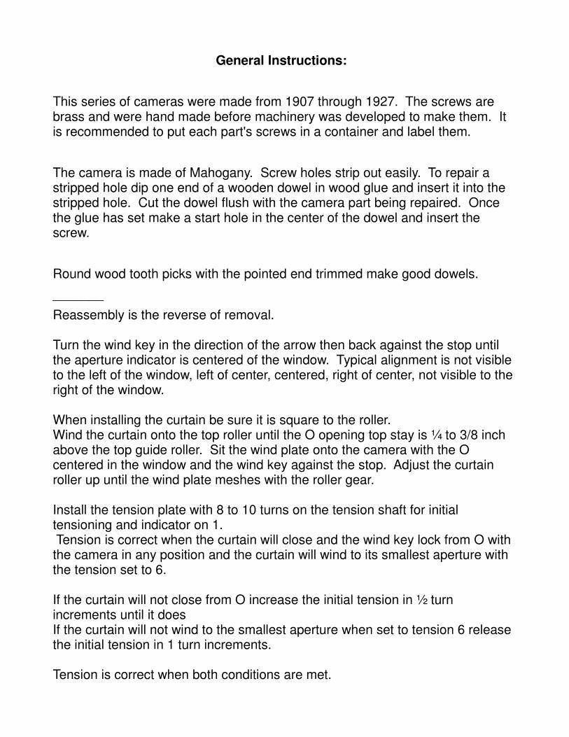
2.
Remove the ground glass retainer spring clip screws then remove the spring clip. Lift the ground glass from the view opening. It is not necessary to remove the rear ground glass retainer.
Always handle a ground glass by its edges.
3.
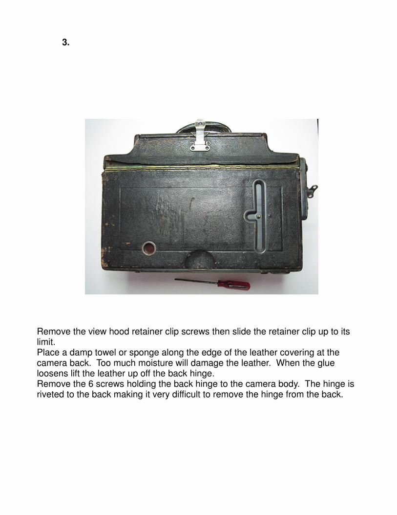
Remove the view hood retainer clip screws then slide the retainer clip up to its limit.Place a damp towel or sponge along the edge of the leather covering at the camera back. Too much moisture will damage the leather. When the glue loosens lift the leather up off the back hinge.Remove the 6 screws holding the back hinge to the camera body. The hinge is riveted to the back making it very difficult to remove the hinge from the back.
4.
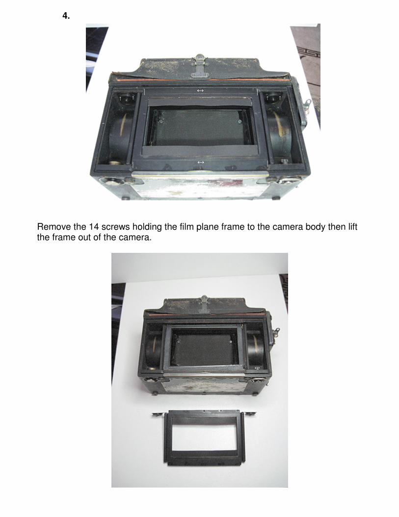
Remove the 14 screws holding the film plane frame to the camera body then lift the frame out of the camera.
5.
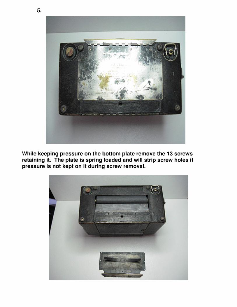
While keeping pressure on the bottom plate remove the 13 screws
retaining it. The plate is spring loaded and will strip screw holes if
pressure is not kept on it during screw removal.
6.
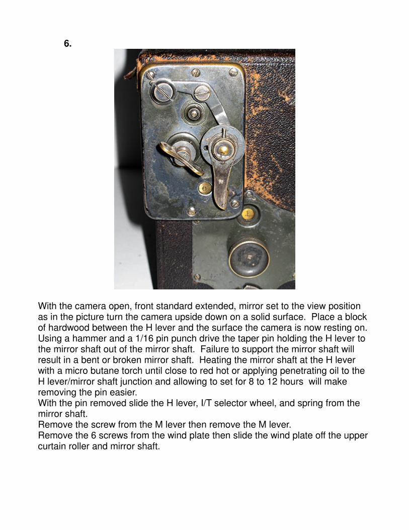
With the camera open, front standard extended, mirror set to the view position as in the picture turn the camera upside down on a solid surface. Place a block of hardwood between the H lever and the surface the camera is now resting on. Using a hammer and a 1/16 pin punch drive the taper pin holding the H lever to the mirror shaft out of the mirror shaft. Failure to support the mirror shaft will result in a bent or broken mirror shaft. Heating the mirror shaft at the H lever with a micro butane torch until close to red hot or applying penetrating oil to the H lever/mirror shaft junction and allowing to set for 8 to 12 hours will make removing the pin easier.With the pin removed slide the H lever, I/T selector wheel, and spring from the mirror shaft.Remove the screw from the M lever then remove the M lever.Remove the 6 screws from the wind plate then slide the wind plate off the upper curtain roller and mirror shaft.
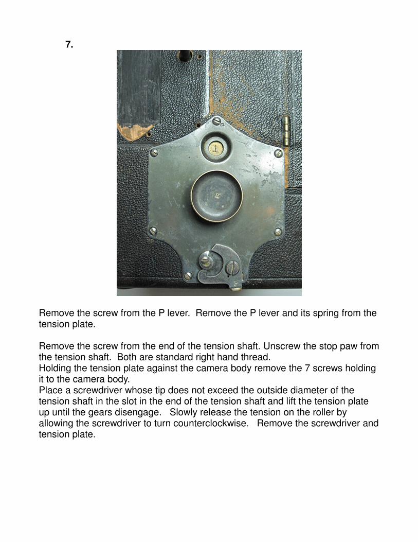
7.
Remove the screw from the P lever. Remove the P lever and its spring from the tension plate.
Remove the screw from the end of the tension shaft. Unscrew the stop paw fromthe tension shaft. Both are standard right hand thread.Holding the tension plate against the camera body remove the 7 screws holding it to the camera body.Place a screwdriver whose tip does not exceed the outside diameter of the tension shaft in the slot in the end of the tension shaft and lift the tension plate up until the gears disengage. Slowly release the tension on the roller by allowing the screwdriver to turn counterclockwise. Remove the screwdriver andtension plate.
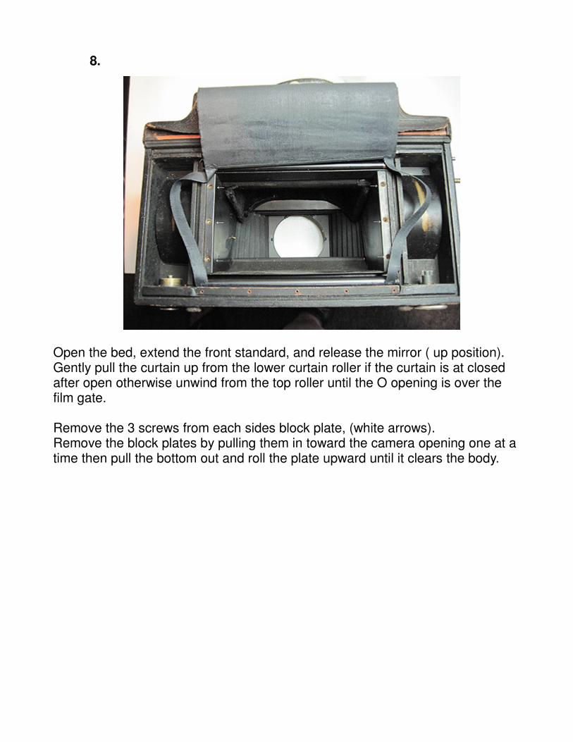
8.
Open the bed, extend the front standard, and release the mirror ( up position).Gently pull the curtain up from the lower curtain roller if the curtain is at closed after open otherwise unwind from the top roller until the O opening is over the film gate.
Remove the 3 screws from each sides block plate, (white arrows). Remove the block plates by pulling them in toward the camera opening one at a time then pull the bottom out and roll the plate upward until it clears the body.
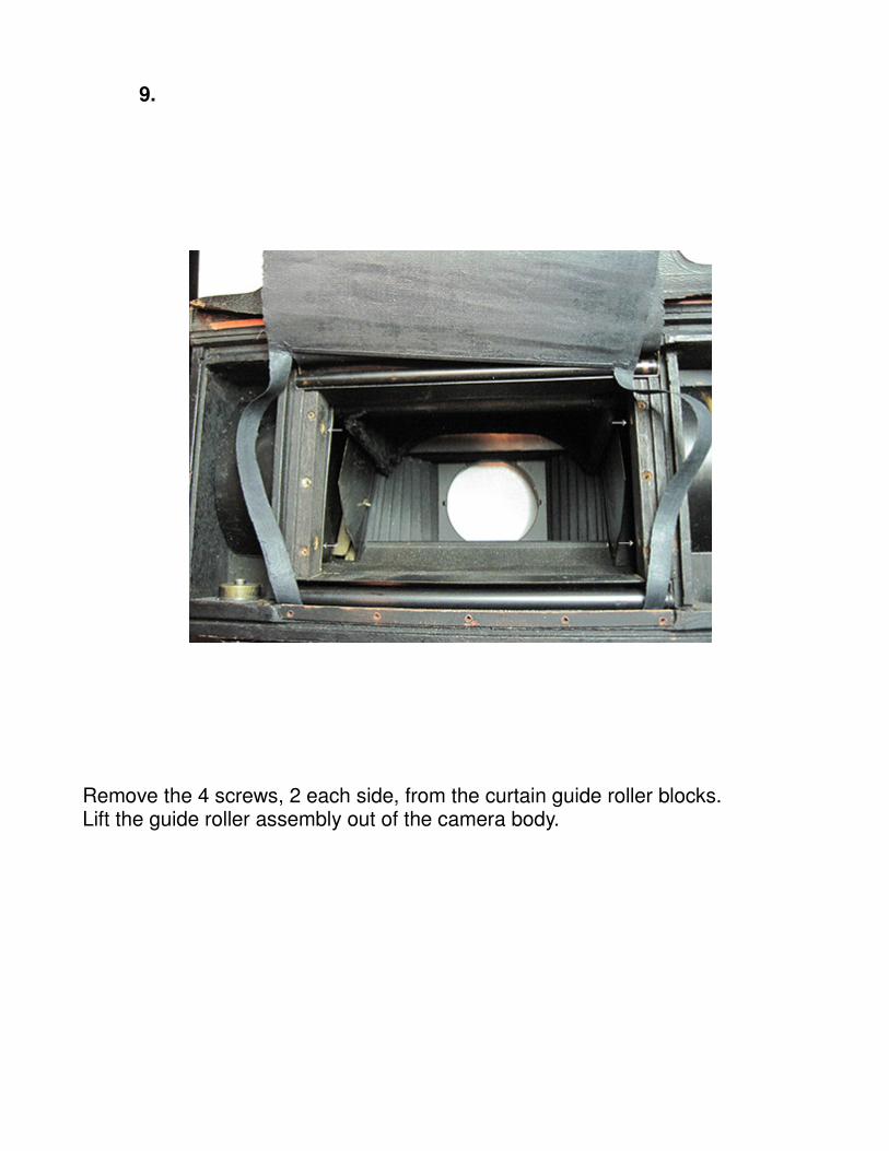
9.
Remove the 4 screws, 2 each side, from the curtain guide roller blocks.Lift the guide roller assembly out of the camera body.
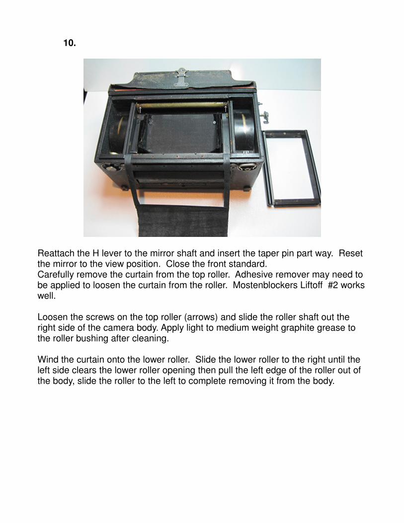
10.
Reattach the H lever to the mirror shaft and insert the taper pin part way. Reset the mirror to the view position. Close the front standard. Carefully remove the curtain from the top roller. Adhesive remover may need to be applied to loosen the curtain from the roller. Mostenblockers Liftoff #2 workswell.
Loosen the screws on the top roller (arrows) and slide the roller shaft out the right side of the camera body. Apply light to medium weight graphite grease to the roller bushing after cleaning.
Wind the curtain onto the lower roller. Slide the lower roller to the right until the left side clears the lower roller opening then pull the left edge of the roller out of the body, slide the roller to the left to complete removing it from the body.
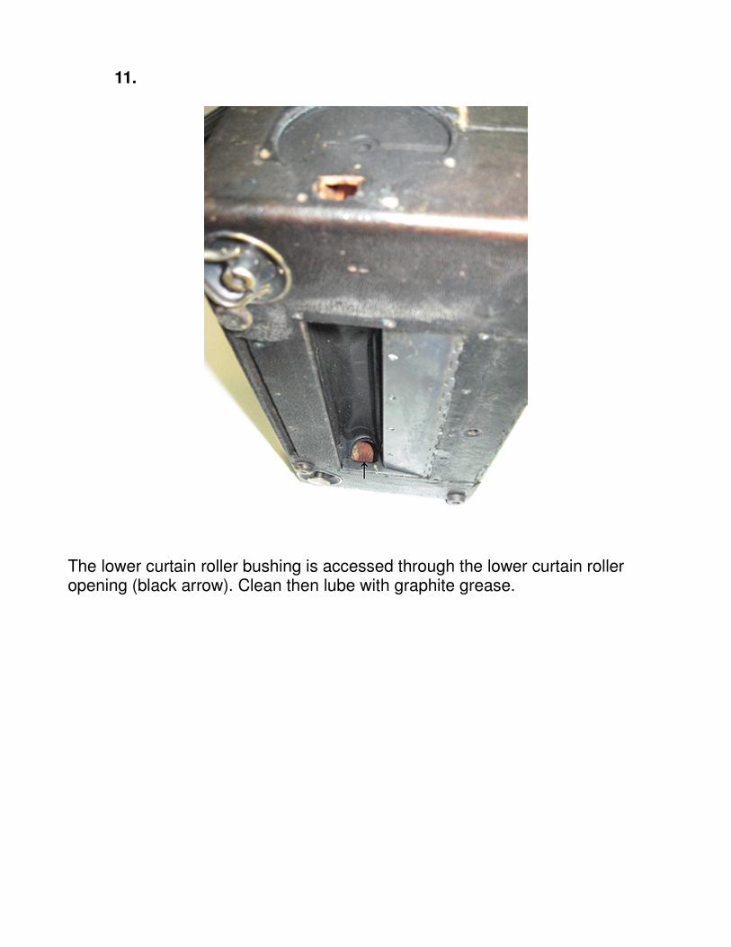
11.
The lower curtain roller bushing is accessed through the lower curtain roller opening (black arrow). Clean then lube with graphite grease.
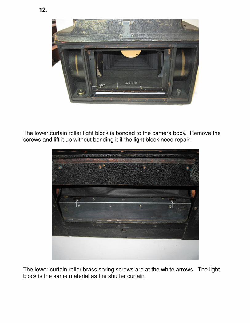
12.
The lower curtain roller light block is bonded to the camera body. Remove the screws and lift it up without bending it if the light block need repair.
The lower curtain roller brass spring screws are at the white arrows. The light block is the same material as the shutter curtain.
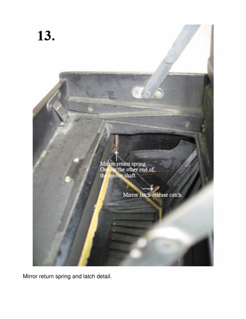
Mirror return spring and latch detail.
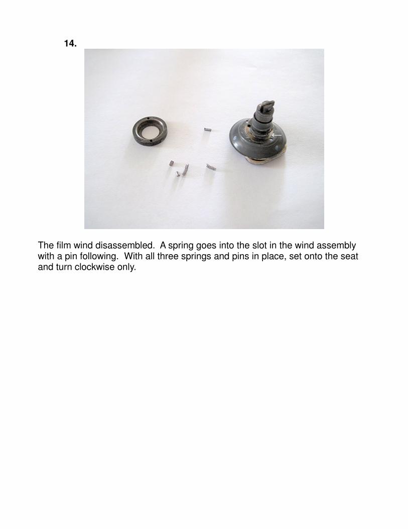
14.
The film wind disassembled. A spring goes into the slot in the wind assembly with a pin following. With all three springs and pins in place, set onto the seat and turn clockwise only.