Embed Size (px)
Citation preview
396-001670 SureFire Flow Indicator with Dual Metering Tube Page 1 Revised 02/26/2016
SureFire Flow Indicator with Dual Metering Tube Plumbing Kits
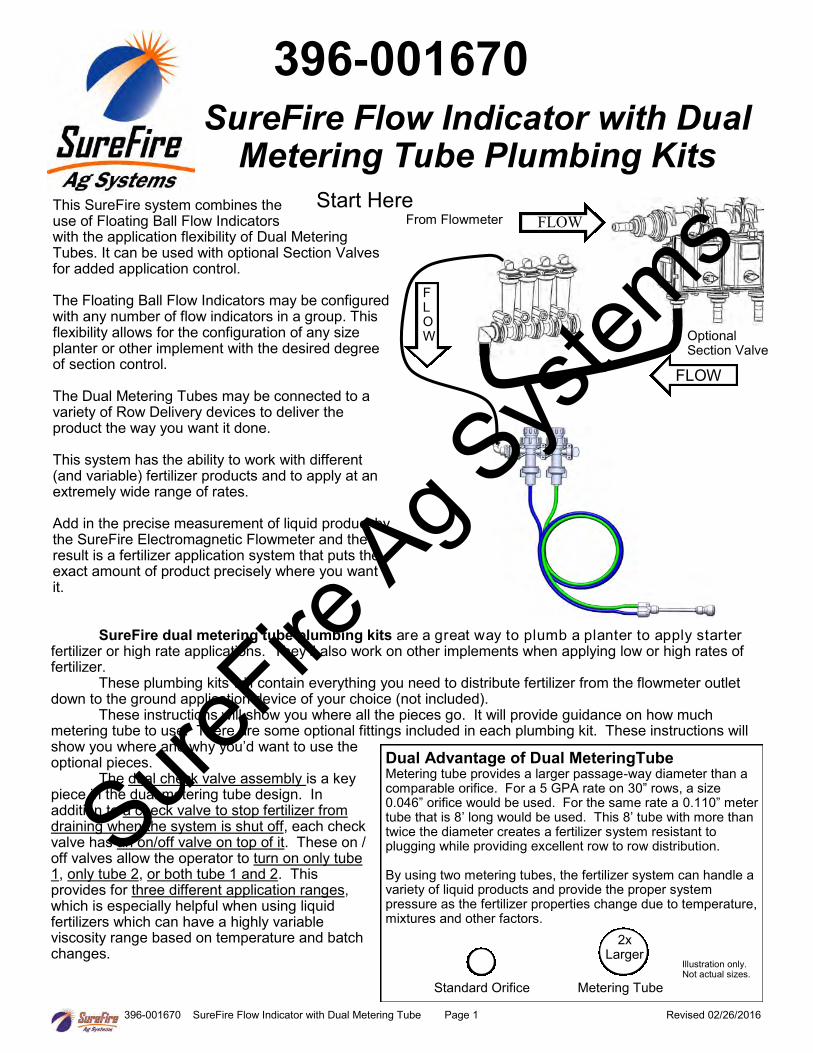
SureFire dual metering tube plumbing kits are a great way to plumb a planter to apply starter fertilizer or high rate applications. They’ll also work on other implements when applying low or high rates of fertilizer. These plumbing kits will contain everything you need to distribute fertilizer from the flowmeter outlet down to the ground application device of your choice (not included). These instructions will show you where all the pieces go. It will provide guidance on how much metering tube to use. There are some optional fittings included in each plumbing kit. These instructions will show you where and why you’d want to use the optional pieces. The dual check valve assembly is a key piece in the dual metering tube design. In addition to a check valve to stop fertilizer from draining when the system is shut off, each check valve has an on/off valve on top of it. These on / off valves allow the operator to turn on only tube 1, only tube 2, or both tube 1 and 2. This provides for three different application ranges, which is especially helpful when using liquid fertilizers which can have a highly variable viscosity range based on temperature and batch changes.
Dual Advantage of Dual MeteringTube Metering tube provides a larger passage-way diameter than a comparable orifice. For a 5 GPA rate on 30” rows, a size 0.046” orifice would be used. For the same rate a 0.110” meter tube that is 8’ long would be used. This 8’ tube with more than twice the diameter creates a fertilizer system resistant to plugging while providing excellent row to row distribution. By using two metering tubes, the fertilizer system can handle a variety of liquid products and provide the proper system pressure as the fertilizer properties change due to temperature, mixtures and other factors.
Standard Orifice Metering Tube
2x Larger
396-001670
FLOW
From Flowmeter FLOW
F L O W
Start Here This SureFire system combines the use of Floating Ball Flow Indicators with the application flexibility of Dual Metering Tubes. It can be used with optional Section Valves for added application control. The Floating Ball Flow Indicators may be configured with any number of flow indicators in a group. This flexibility allows for the configuration of any size planter or other implement with the desired degree of section control. The Dual Metering Tubes may be connected to a variety of Row Delivery devices to deliver the product the way you want it done. This system has the ability to work with different (and variable) fertilizer products and to apply at an extremely wide range of rates. Add in the precise measurement of liquid product by the SureFire Electromagnetic Flowmeter and the result is a fertilizer application system that puts the exact amount of product precisely where you want it.
Optional Section Valve
Illustration only. Not actual sizes.
SureFire
Ag Sys
tems
396-001670 SureFire Flow Indicator with Dual Metering Tube Page 2 Revised 02/26/2016
701-20521-00 End Cap
400-1036A2 7-12 Row Bracket
101-100075BRB 1” MPT x 3/4” HB
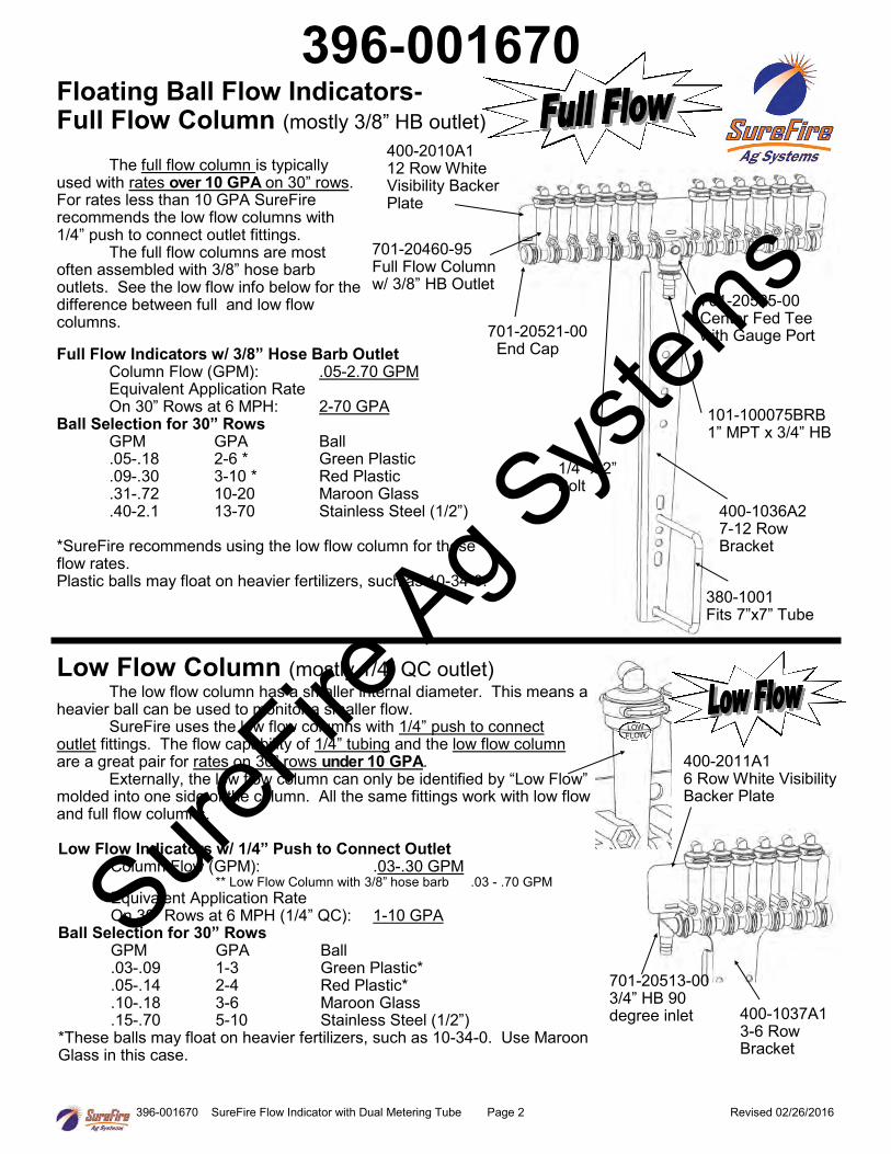
The full flow column is typically used with rates over 10 GPA on 30” rows. For rates less than 10 GPA SureFire recommends the low flow columns with 1/4” push to connect outlet fittings. The full flow columns are most often assembled with 3/8” hose barb outlets. See the low flow info below for the difference between full and low flow columns.
701-20460-95 Full Flow Column w/ 3/8” HB Outlet
701-20525-00 Center Fed Tee with Gauge Port
380-1001 Fits 7”x7” Tube
Full Flow Indicators w/ 3/8” Hose Barb Outlet Column Flow (GPM): .05-2.70 GPM Equivalent Application Rate On 30” Rows at 6 MPH: 2-70 GPA
Ball Selection for 30” Rows GPM GPA Ball .05-.18 2-6 * Green Plastic .09-.30 3-10 * Red Plastic .31-.72 10-20 Maroon Glass .40-2.1 13-70 Stainless Steel (1/2”)
*SureFire recommends using the low flow column for these flow rates. Plastic balls may float on heavier fertilizers, such as 10-34-0.
1/4” x 2” Bolt
Floating Ball Flow Indicators- Full Flow Column (mostly 3/8” HB outlet)
400-2010A1 12 Row White Visibility Backer Plate
400-1037A1 3-6 Row Bracket
400-2011A1 6 Row White Visibility Backer Plate
701-20513-00 3/4” HB 90 degree inlet
Low Flow Column (mostly 1/4” QC outlet) The low flow column has a smaller internal diameter. This means a heavier ball can be used to monitor a smaller flow. SureFire uses the low flow columns with 1/4” push to connect outlet fittings. The flow capability of 1/4” tubing and the low flow column are a great pair for rates on 30” rows under 10 GPA. Externally, the low flow column can only be identified by “Low Flow” molded into one side of the column. All the same fittings work with low flow and full flow columns.
Low Flow Indicators w/ 1/4” Push to Connect Outlet Column Flow (GPM): .03-.30 GPM ** Low Flow Column with 3/8” hose barb .03 - .70 GPM Equivalent Application Rate On 30” Rows at 6 MPH (1/4” QC): 1-10 GPA
Ball Selection for 30” Rows GPM GPA Ball .03-.09 1-3 Green Plastic* .05-.14 2-4 Red Plastic* .10-.18 3-6 Maroon Glass .15-.70 5-10 Stainless Steel (1/2”)
*These balls may float on heavier fertilizers, such as 10-34-0. Use Maroon Glass in this case.
396-001670
SureFire
Ag Sys
tems
396-001670 SureFire Flow Indicator with Dual Metering Tube Page 3 Revised 02/26/2016
Floating Ball Flow Indicators
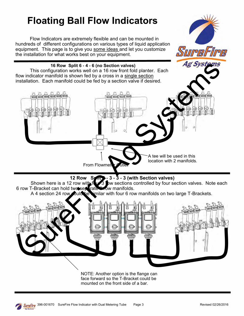
Flow Indicators are extremely flexible and can be mounted in hundreds of different configurations on various types of liquid application equipment. This page is to give you some ideas and let you customize the installation for what works best on your equipment.
From Flowmeter Outlet
16 Row Split 6 - 4 - 6 (no Section valves) This configuration works well on a 16 row front fold planter. Each flow indicator manifold is shown fed by a cross in a single section installation. Each manifold could be fed by a section valve if desired.
A tee will be used in this location with 2 manifolds.
NOTE: Another option is the flange can face forward so the T-Bracket could be mounted on the front side of a bar.
12 Row Split 3 - 3 - 3 - 3 (with Section valves) Shown here is a 12 row with four 3 row sections controlled by four section valves. Note each 6 row T-Bracket can hold two separate 3 row manifolds. A 4 section 24 row could be similar with four 6 row manifolds on two large T-Brackets.
SureFire
Ag Sys
tems
396-001670 SureFire Flow Indicator with Dual Metering Tube Page 4 Revised 02/26/2016
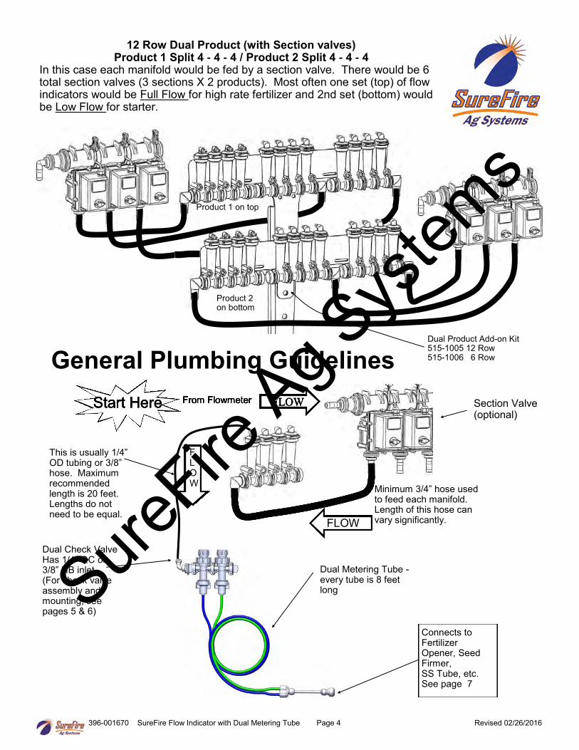
Connects to Fertilizer Opener, Seed Firmer, SS Tube, etc. See page 7
General Plumbing Guidelines From Flowmeter
Minimum 3/4” hose used to feed each manifold. Length of this hose can vary significantly.
This is usually 1/4” OD tubing or 3/8” hose. Maximum recommended length is 20 feet. Lengths do not need to be equal.
12 Row Dual Product (with Section valves) Product 1 Split 4 - 4 - 4 / Product 2 Split 4 - 4 - 4
In this case each manifold would be fed by a section valve. There would be 6 total section valves (3 sections X 2 products). Most often one set (top) of flow indicators would be Full Flow for high rate fertilizer and 2nd set (bottom) would be Low Flow for starter.
Dual Product Add-on Kit 515-1005 12 Row 515-1006 6 Row
Product 1 on top
Product 2 on bottom
Dual Check Valve Has 1/4” QC or 3/8” HB inlet (For check valve assembly and mounting, see pages 5 & 6)
Section Valve (optional)
FLOW Start Here From Flowmeter FLOW Start Here
F L O W
From Flowmeter FLOW Start Here
FLOW
From Flowmeter FLOW Start Here
Dual Metering Tube - every tube is 8 feet long Sure
Fire Ag S
ystem
s
396-001670 SureFire Flow Indicator with Dual Metering Tube Page 5 Revised 02/26/2016
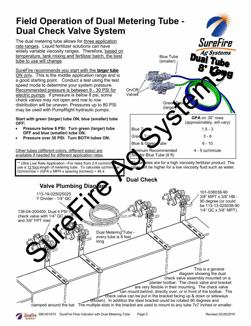
Dual Check Valve Plumbing Diagram
136-04-200400, Dual 4 PSI check valve with 1/4” QC caps and 3/8” FPT inlet
101-038038-90 3/8” MPT x 3/8” HB - 90 degree (or could be 113-13-025038-90 1/4” QC x 3/8” MPT)
113-19-025025025 Y Divider - 1/4” QC
This is a general diagram showing the dual check valve assembly mounted on a planter toolbar. The check valve and bracket are very flexible in their mounting. The check valve can mount behind, directly over, or in front of the toolbar. The check valve can be put in the bracket facing up & down or sideways (shown). In addition the steel bracket could be rotated 90 degrees and clamped around the bar. The multiple slots in the bracket are used to mount to any tube 7x7 inches or smaller.
Field Operation of Dual Metering Tube - Dual Check Valve System The dual metering tube allows for three application rate ranges. Liquid fertilizer solutions can have widely variable viscosity ranges. Therefore, based on temperature, tank mixing and fertilizer batch, the best tube to use will change. SureFire recommends you start with the larger tube ON only. This is the middle application range and is a good starting point. Conduct a test using the test speed mode to determine your system pressure. Recommended pressure is between 8 - 30 PSI for electric pumps. If pressure is below 8 psi, some check valves may not open and row to row distribution will be uneven. Pressures up to 80 PSI may be used with PumpRight hydraulic pumps. Start with green (larger) tube ON, blue (smaller) tube OFF:
Pressure below 8 PSI: Turn green (larger) tube OFF and blue (smaller) tube ON.
Pressure over 30 PSI: Turn BOTH tubes ON.
Blue Tube (smaller)
Green Tube (larger)
GPA on 30” rows (approximately, will vary)
Blue Tube 1.5 - 3
Green Tube 3 - 6
Blue & Green Tube 6 - 10
Minimum Recommended flow for Blue Tube (8 ft)
4 - 5 oz/minute
** Ultra Low Rate Application –For rates from 2-5 oz/min/row use a 12 foot length of metering tube. To calculate oz/min/row: Oz/min/row = (GPA x MPH x spacing (inches)) ÷ 46.4
On/Off Valves
These rates are for a high viscosity fertilizer product. The rates will be higher for a low viscosity fluid such as water.
Other tubes (different colors, different sizes) are available if needed for different application rates.
Dual Metering Tube - every tube is 8 feet long
SureFire
Ag Sys
tems
396-001670 SureFire Flow Indicator with Dual Metering Tube Page 6 Revised 02/26/2016
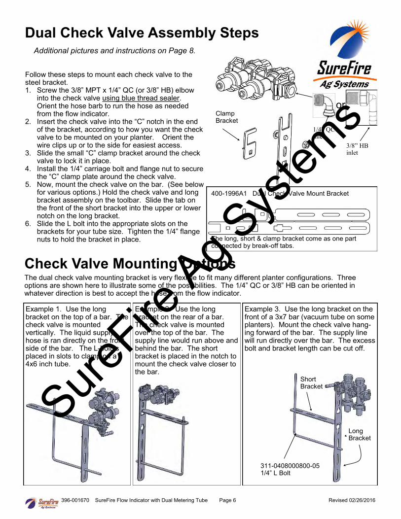
Dual Check Valve Assembly Steps
Additional pictures and instructions on Page 8. Follow these steps to mount each check valve to the steel bracket. 1. Screw the 3/8” MPT x 1/4” QC (or 3/8” HB) elbow
into the check valve using blue thread sealer. Orient the hose barb to run the hose as needed from the flow indicator.
2. Insert the check valve into the “C” notch in the end of the bracket, according to how you want the check valve to be mounted on your planter. Orient the wire clips up or to the side for easiest access.
3. Slide the small “C” clamp bracket around the check valve to lock it in place.
4. Install the 1/4” carriage bolt and flange nut to secure the “C” clamp plate around the check valve.
5. Now, mount the check valve on the bar. (See below for various options.) Hold the check valve and long bracket assembly on the toolbar. Slide the tab on the front of the short bracket into the upper or lower notch on the long bracket.
6. Slide the L bolt into the appropriate slots on the brackets for your tube size. Tighten the 1/4” flange nuts to hold the bracket in place.
Clamp Bracket
400-1996A1 Dual Check Valve Mount Bracket
The long, short & clamp bracket come as one part connected by break-off tabs.
Check Valve Mounting Options The dual check valve mounting bracket is very flexible to fit many different planter configurations. Three options are shown here to illustrate some of the possibilities. The 1/4” QC or 3/8” HB can be oriented in whatever direction is best to accept the hose from the flow indicator.
Example 1. Use the long bracket on the top of a bar. The check valve is mounted vertically. The liquid supply hose is ran directly on the front side of the bar. The L-bolt is placed in slots to clamp on a 4x6 inch tube.
Example 2. Use the long bracket on the rear of a bar. The check valve is mounted over the top of the bar. The supply line would run above and behind the bar. The short bracket is placed in the notch to mount the check valve closer to the bar.
Example 3. Use the long bracket on the front of a 3x7 bar (vacuum tube on some planters). Mount the check valve hang-ing forward of the bar. The supply line will run directly over the bar. The excess bolt and bracket length can be cut off.
311-0408000800-05 1/4” L Bolt
Short Bracket
Long Bracket
1/4” QC inlet
3/8” HB inlet
or
SureFire
Ag Sys
tems
396-001670 SureFire Flow Indicator with Dual Metering Tube Page 7 Revised 02/26/2016
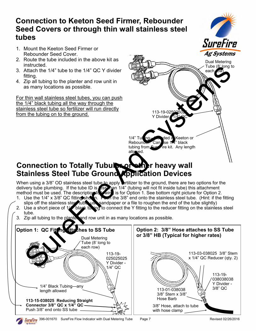
Connection to Keeton Seed Firmer, Rebounder Seed Covers or through thin wall stainless steel tubes
1. Mount the Keeton Seed Firmer or Rebounder Seed Cover.
2. Route the tube included in the above kit as instructed.
3. Attach the 1/4” tube to the 1/4” QC Y divider fitting.
4. Zip all tubing to the planter and row unit in as many locations as possible.
For thin wall stainless steel tubes, you can push the 1/4” black tubing all the way through the stainless steel tube so fertilizer will run directly from the tubing on to the ground.
1/4” Tubing—Included in Keeton or Rebounder. Can use 1/4” black tubing from SureFire kit. Any length allowed.
113-19-025025025 Y Divider - 1/4” QC
Dual Metering Tube (8’ long to each row)
Option 1: QC Fitting attaches to SS Tube
113-15-038025 Reducing Straight Connector 3/8” QC x 1/4” QC Push 3/8” end onto SS tube
Connection to Totally Tubular or other heavy wall Stainless Steel Tube Ground Application Devices When using a 3/8” OD stainless steel tube to apply fertilizer to the ground, there are two options for the delivery tube plumbing. If the tube ID is less than 1/4” (tubing will not fit inside tube) this attachment method must be used. The description following is for Option 1. See bottom right picture for Option 2. 1. Use the 1/4” x 3/8” QC fitting shown. Push the 3/8” end onto the stainless steel tube. (Hint: if the fitting
slips off the stainless steel tube, use sandpaper or a file to roughen the end of the tube slightly) 2. Use a short piece of 1/4” black tubing to connect the Y fitting to the reducer fitting on the stainless steel
tube. 3. Zip all tubing to the planter and row unit in as many locations as possible.
Dual Metering Tube (8’ long to each row)
1/4” Black Tubing—any length allowed
113-19-025025025 Y Divider - 1/4” QC
113-19-038038038 Y Divider - 3/8” QC
Option 2: 3/8” Hose attaches to SS Tube or 3/8” HB (Typical for higher rates)
113-03-038025 3/8” Stem x 1/4” QC Reducer (qty. 2)
113-01-038038 3/8” Stem x 3/8” Hose Barb
3/8” Hose, attach to tube with hose clamp
SureFire
Ag Sys
tems
396-001670 SureFire Flow Indicator with Dual Metering Tube Page 8 Revised 02/26/2016
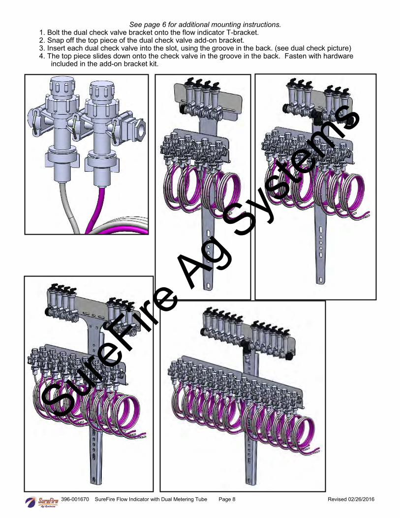
See page 6 for additional mounting instructions. 1. Bolt the dual check valve bracket onto the flow indicator T-bracket. 2. Snap off the top piece of the dual check valve add-on bracket. 3. Insert each dual check valve into the slot, using the groove in the back. (see dual check picture) 4. The top piece slides down onto the check valve in the groove in the back. Fasten with hardware
included in the add-on bracket kit.
SureFire
Ag Sys
tems