Embed Size (px)
DESCRIPTION
aeeae
Citation preview

An intelligent mill analyzer
Outotec MillSense® is an innovative, non-contact analyzer for grinding mills providing real-time information about the mill charge and the grinding process such as total charge volume.
The charge position and volume provided by MillSense® are fundamental factors that affect the state of the grinding process and provide crucial insight on the conditions inside the mill. Along with mill rotation speed, charge characteristics such as toe angle can be used to maximize the breakage energy and therefore optimize the grinding efficiency. Charge volume is also an essential measurement to avoid overloading and underloading, which can cause cuts in ore feed and severe damage to the lining and mill shell. Therefore, a real-time mill charge analyzer is an indispensable part of a modern advanced grinding control.
Outotec MillSense®

Grinding control
Conventional control schemeGrinding control has conventionally been based on the power draw of the mill, with a typical goal of maximizing the power draw in the belief that the more energy is consumed the more energy is used in breaking the ore. This maximum power occurs at a point where overload is imminent and is typically detected by a falling power
draw and a rising mill weight indication. Unfortunately power draw is very sensitive to constantly changing factors such as ore properties, mill speed, ball charge and liner wear, causing the maximum power draw level to vary.
Also, when an overload can reliably be detected from the falling power, the mill is already slightly overloaded and major control actions must be taken to bring the mill back to safe operating range. In addition, the conditions inside the mill have a great effect on how efficiently the total power draw is used in actual breakage, and therefore, maximizing the power draw may actually not achieve the ultimate goal of maximizing breakage.
Using charge volume in controlThe most important factors affecting the breakage efficiency are in fact charge volume and mill speed. Though the effectiveness of the grinding is affected by many other factors that are difficult to measure, they are all linked to the charge behavior. The charge volume – not the mass – is largely responsible for mill overloads and the breakage energy. For instance, a low charge volume results in high-energy impacts as the grinding media falls a greater height from the shoulder down to the toe. However, depending on the charge level, mill speed and current liner profile, some of these high-energy impacts may land beyond the toe, which in excess will cause liner damage. On
002 More out of ore!
Process changes, e.g.feed SG, mill speed,ball charge, etc.
Overload zone in volume
Overload zone in power
Charge volume (%)
Pow
er (k
W)
A single power level canrepresent a wide rage of charge volume when processparameters vary

the other had, an attempt to protect the liners with a too high charge volume results in inefficient impacts, which lowers the grinding efficiency and eventually causes mill overloads. Therefore, a reliable on-line volumetric charge measurement is vital in the control and optimization of a grinding mill.
Since mill weight indicators such as load cells and bearing pressure are affected by variables such as ore density, ball charge and liner wear, they cannot provide an absolute charge volume measurement and are therefore not as suitable as volume or charge position measurements. This is why there has recently been an increasing interest in absolute volume measurement and estimation techniques.
Advanced grinding control solutionMillSense® is a basis for an advanced control solution and is well accompanied by other advanced instrumentation such as Outotec PSI® on-line particle size analyzers, ore feed size analyzers and automatic ball addition systems. Outotec has extensive experience in providing expert control solutions (Outotec® ACT) for grinding circuits. When Outotec’s advanced control solution is applied, the variation of process parameters
is reduced, the desired particle size distribution is maintained and the throughput of the mill is optimized. This ensures cost-effective, trouble-free and efficient operation of grinding circuits as well as a steady feed to downstream processes.
More out of ore! 003
53.9 º
226.5 ºToe
Shoulder
200 210 220 230 240 250 260
5040
3020
10
33.4 %
Optimum
Charge volume (%)
Spee
d (%
of c
ritic
al)
Reduced impact area
Liner damage
Liner damage
Reduced impact area
Inefficientimpacts

Outotec MillSense® Analyzer
Non-contact charge measurementMost of currently available mill charge measurement systems are intrusive, that is, they require instruments to be placed in a hostile environment inside the mill or on the outside shell. This has several disadvantages such as instrument wear and continuous replacement needs, difficulties in power supply of the sensor and a need for wireless signal transfer. This amounts to complex instrumentation and extensive maintenance needs. Attempts have also been made to employ models and more easily available measurements, but they can be difficult to commission and maintain accurate.
MillSense® is a non-contact analyzer, which makes use of high-frequency sampling of the mill motor’s current draw with special fast response current sensors. An inductive proximity switch is used for synchronization and accurate speed measurement. With this simple instrumentation Outotec can provide a robust charge analyzer with little need for maintenance. In addition MillSense® does not impose any major restrictions on the lining type or material.
Measurement principleOutotec MillSense® is based on the patented use of a ripple present in mill motor’s current draw caused by lifters as they impact the charge. Changes in the charge position are seen as detectable variations in the ripple. Recent developments in the analysis of the ripple have enabled the use of this phenomenon in many different mill configurations.
The method uses advanced mathematical tools and specific knowledge of the mill and the lining to determine the charge position accurately and robustly. Noise and other disturbing variance in the current – caused, for instance, by mechanical asymmetries – are effectively filtered out by the data analysis.
MillSense® also has an automatic speed compensation algorithm, which allows its use in modern speed-controlled mills.
Outotec MillSense® Analyzer systemMillSense® consists of a main MillSense® Analyzer Cabinet (MAC) and multiple Signal Junction Cabinets (SJC, one for each drive).
004 More out of ore!
The junction cabinets are located near the current measurement points for the main power lines of the mill motors while the main cabinet can be freely placed. The cabinets are connected with a dedicated fiber optic Ethernet-network. Inside the main analyzer unit, the signals are collected and analyzed in an industrial high-performance computer. The analyzer provides operators with user interface via a standard Web browser with monitoring functionalities. In the case of more advanced requirements or configuration, a remote desktop connection can be used to manage the analyzer.
A single analyzer is capable of analyzing the charge of up to four mills. Analysis results and calculated measurements can be transferred to third party systems via the provided OPC Server or the integrated SQL database.
More out of ore! 005
BC
FS
DC
WIC
FIC
PT WT
JT TT
SIC
FIC
DCDC
LIC
FT
DICA
MS
JIC PSI
M
M
M
M
M
M
M
Ball feeder
Ball addition
Feed size
Fresh feed
Water
Density control
Water
Level control
Density control
Pump sump
Ball mill
Cyclone battery
Ball addition
Particle size
Acoustic
MillSense charge analyzer
Bearing pressure / Load cells
Power / Torque
Speed control
PT
SAG mill

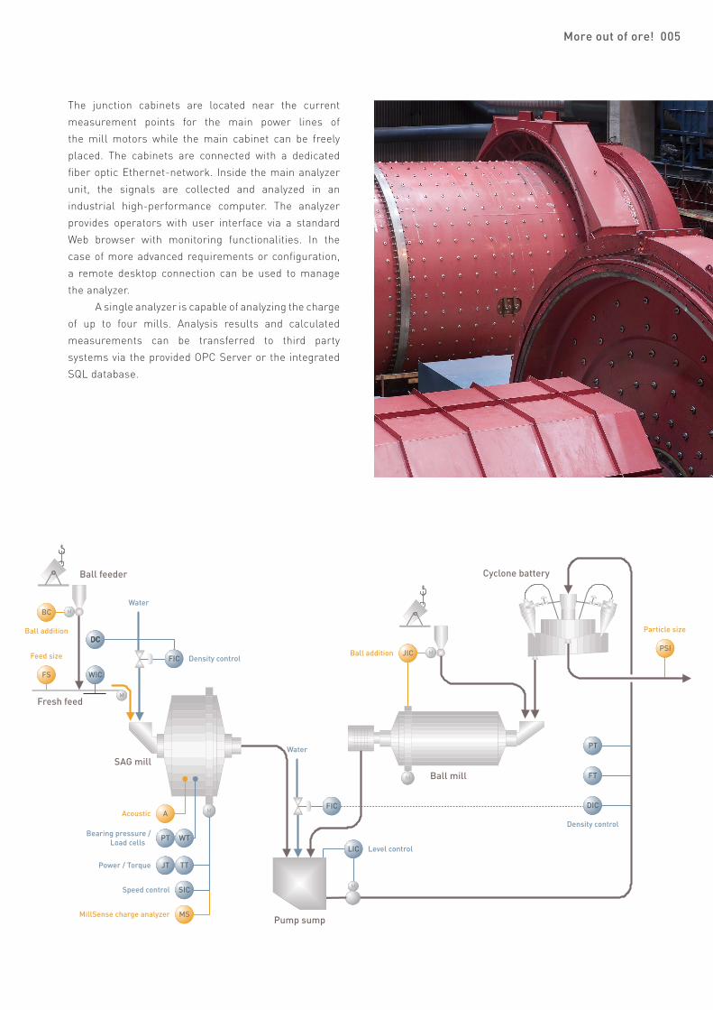
MillSense® General System Layout
Typical location of MillSense® Current Sensors with different mill drives
006 More out of ore!
Variable speed drive with a frequency converter Fixed speed
f1f2
MV
M3 ~
M3 ~
MV
Electrical Room
Mill
Electrical Room
Mill
Switchgear
Transformer bunker
Frequency converter
cabinet
Circuit breaker
Step down Transformer
Frequency converter
MillSense® Current Sensors
MillSense® Current Sensors
Mill motor 0 - 100% speed
Mill motorFixed speed
Liquid resistance starter (LRS)
SwitchgearCircuit breaker
Mill 1 (single drive)
115/230VAC
Signal JunctionCabinet
Current sensors
Rotationsensor
115/230VAC
Signal JunctionCabinet
Mill 3 (single drive)
Current sensors
Rotationsensor
115/230VAC
Signal JunctionCabinet
Current sensors
115/230VAC
Signal JunctionCabinet
Current sensors
Rotationsensor
Mill 2 (dual motor drive)
115/230VAC
Control room OutotecRemote support
Plant network
Automation
Electrical roomPlant floor
EtherCATnetwork
EtherCATnetwork
EtherCATnetwork
EtherCATnetwork
Ethernet (copper)EtherCAT (fiber optic)Current signal cableDigital signal cable
MillSense® AnalyzerCabinet
Local access

Performance
Suitability: For primary AG and SAG mills
Number of measured mills: 1 to 4
Measurement update interval: Once in a revolution
System components
Current sensors (one for each current phase and drive of each mill)
Inductive proximity switch (one for each mill)
Signal Junction Cabinet SJC (one for each drive of each mill)
MillSense® Analyzer Cabinet MAC (one for up to four mills)
Operator interface PC (optional)
Remote monitoring PC (optional)
Web server user interface
Main status and event log
Mill-specific status with graphical representation of charge
Trending, measurement monitoring
Event log
Retrieval of measurement data from the integrated database
Measurement outputs
Charge toe and shoulder angle
Ripple amplitude
Full scripting environment (VBScript) available for customized calculations
User configurable model based estimators (Extended Kalman Filter)
Data connections
Control system connection:• Ethernet OPC Server• Via integrated SQL database• COM component interface (ActiveX)• Customized connections upon request
Remote diagnostics connection: Ethernet or dial up modem line
Remote display and configuration: Web server, remote desktop connection
Installation requirements
Operating ambient temperature at sea level: +5 - +45 °C (41-113 °F)
Environmental classification: IP56 (Designed to meet NEMA 4X)
Power supply: 115 / 230 VAC ± 10% 60 / 50 Hz (MAC and SJC)
Dimensions: • MAC: 600 x 378 x 221 mm (H x W x D) 23.6 x 14.9 x 8.7 “(H x W x D)• SJC: 600 x 278 x 221 mm (H x W x D) 23.6 x 10.9 x 8.7 “(H x W x D)
Weight: • MAC 27 kg (60 lbs)• SJC 20 kg (44 lbs)
Outotec quality assurance
Outotec MillSense® is CE marked according to the European Union Directives. Outotec is ISO 9001 accredited
and has a quality management policy to ensure that the expectations of customers are met.
Specifications for Outotec MillSense®
More out of ore! 007

[email protected] © 2009 Outotec Oyj. All rights reserved.