Embed Size (px)
Citation preview
Series 392
Instruction Manual
Granville-Phillips® Series 392 Micro-Ion® Plus Two-Sensor Combination Vacuum Gauge Modulewith DeviceNetTM and RS-485 Interface,and Analog Output
Instruction manual part number 392002
Revision G - January 2015

Series 392
Instruction Manual
This Instruction Manual is for use with all Granville-Phillips Series 392 Micro-Ion Plus Modules with DeviceNet and RS-485 Interface, and Analog Output. A list of applicable catalog numbers is provided on the following page.
These products are RoHS compliant.
Granville-Phillips® Series 392 Micro-Ion® Plus Two-Sensor Combination Vacuum Gauge Modulewith DeviceNetTM and RS-485 Interface,and Analog Output
For Customer Service or Technical Support 24 hours per day, 7 days per week, every day of the year including holidays:Phone: +1-800-227-8766 or +1-303-652-4691
MKS, Granville-Phillips Division6450 Dry Creek ParkwayLongmont, CO 80503 USA
Phone: 1-303-652-4691 or 1-800-776-6543 FAX: 1-303-652-2844Email: [email protected]
Corporate OfficeMKS Instruments, Inc.2 Tech Drive, Suite 201Andover, MA 01810 USA
Phone: 1-978-645-5500www.mksinst.com
© 2015 MKS Instruments, Inc. All rights reserved. Granville-Phillips®, Micro-Ion®, and Conductron® are registered trademarks of MKS Instruments, Inc. All other trademarks and registered trademarks are the properties of their respective owners.
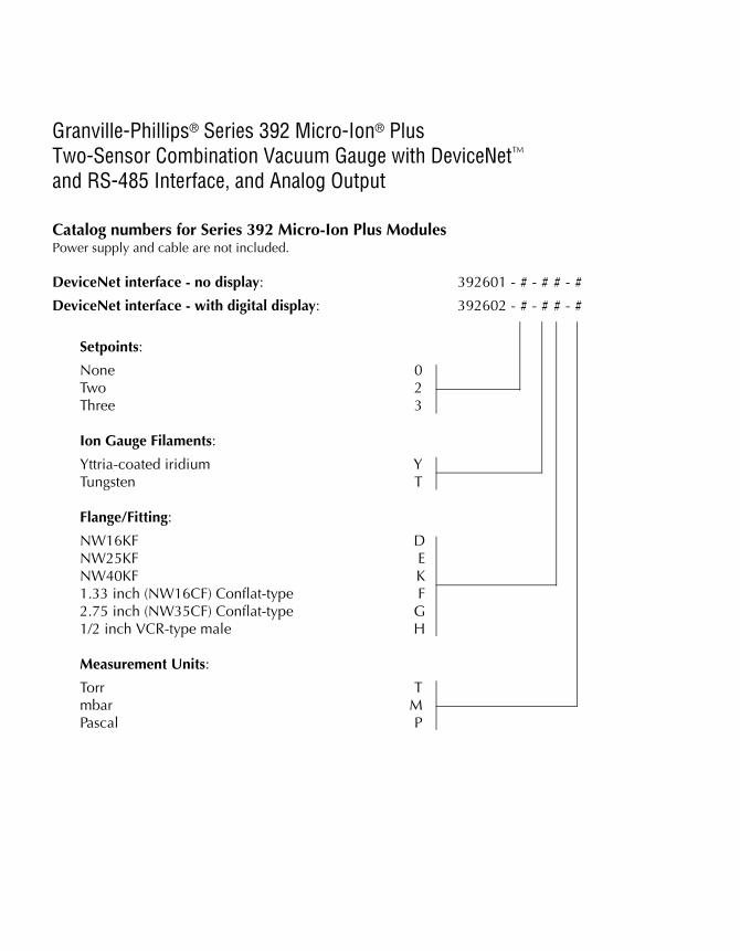
Granville-Phillips® Series 392 Micro-Ion® PlusTwo-Sensor Combination Vacuum Gauge with DeviceNet™and RS-485 Interface, and Analog Output
Catalog numbers for Series 392 Micro-Ion Plus ModulesPower supply and cable are not included.
DeviceNet interface - no display: 392601 - # - # # - #
DeviceNet interface - with digital display: 392602 - # - # # - #
Setpoints:
None 0Two 2Three 3
Ion Gauge Filaments:
Yttria-coated iridium YTungsten T
Flange/Fitting:
NW16KF DNW25KF ENW40KF K1.33 inch (NW16CF) Conflat-type F2.75 inch (NW35CF) Conflat-type G1/2 inch VCR-type male H
Measurement Units:
Torr Tmbar MPascal P
Micro-Ion® Plus Module Instruction Manual - 392002 - Rev. G 5
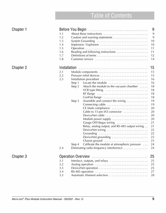
Table of Contents
Chapter 1 Before You Begin . . . . . . . . . . . . . . . . . . . . . . . . . . . . . . . . . . . . 91.1 About these instructions . . . . . . . . . . . . . . . . . . . . . . . . . . . 91.2 Caution and warning statements . . . . . . . . . . . . . . . . . . . . . 91.3 System Grounding . . . . . . . . . . . . . . . . . . . . . . . . . . . . . . . 101.4 Implosion / Explosion . . . . . . . . . . . . . . . . . . . . . . . . . . . . . 101.5 Operation . . . . . . . . . . . . . . . . . . . . . . . . . . . . . . . . . . . . . . 111.6 Reading and following instructions . . . . . . . . . . . . . . . . . . . 111.7 Definitions of terms . . . . . . . . . . . . . . . . . . . . . . . . . . . . . . . 121.8 Customer service . . . . . . . . . . . . . . . . . . . . . . . . . . . . . . . . 14
Chapter 2 Installation . . . . . . . . . . . . . . . . . . . . . . . . . . . . . . . . . . . . . . . . . . 152.1 Module components . . . . . . . . . . . . . . . . . . . . . . . . . . . . . . 152.2 Pressure relief devices . . . . . . . . . . . . . . . . . . . . . . . . . . . . . 152.3 Installation procedure . . . . . . . . . . . . . . . . . . . . . . . . . . . . . 16
Step 1 Locate the module . . . . . . . . . . . . . . . . . . . . . . . . 16Step 2 Attach the module to the vacuum chamber . . . . . 18
VCR type fitting . . . . . . . . . . . . . . . . . . . . . . . . . . 18KF flange . . . . . . . . . . . . . . . . . . . . . . . . . . . . . . . 18ConFlat flange . . . . . . . . . . . . . . . . . . . . . . . . . . . 18
Step 3 Assemble and connect the wiring . . . . . . . . . . . . . 19Connecting cable . . . . . . . . . . . . . . . . . . . . . . . . . 19CE Mark compliance . . . . . . . . . . . . . . . . . . . . . . 20Cable to 15-pin I/O connector . . . . . . . . . . . . . . . 20DeviceNet cable . . . . . . . . . . . . . . . . . . . . . . . . . . 20Module power supply . . . . . . . . . . . . . . . . . . . . . . 20Gauge OFF/degas wiring . . . . . . . . . . . . . . . . . . . 21Relay, analog output, and RS-485 output wiring . . 21DeviceNet wiring . . . . . . . . . . . . . . . . . . . . . . . . . 22Grounding . . . . . . . . . . . . . . . . . . . . . . . . . . . . . . 22DeviceNet grounding . . . . . . . . . . . . . . . . . . . . . . 23Chassis ground . . . . . . . . . . . . . . . . . . . . . . . . . . . 23
Step 4 Calibrate the module at atmospheric pressure . . . 242.4 Eliminating radio frequency interference . . . . . . . . . . . . . . . 24
Chapter 3 Operation Overview . . . . . . . . . . . . . . . . . . . . . . . . . . . . . . . . . . 253.1 Interface, outputs, and relays . . . . . . . . . . . . . . . . . . . . . . . 253.2 Analog operation . . . . . . . . . . . . . . . . . . . . . . . . . . . . . . . . 253.3 DeviceNet operation . . . . . . . . . . . . . . . . . . . . . . . . . . . . . . 253.4 RS-485 operation . . . . . . . . . . . . . . . . . . . . . . . . . . . . . . . . 273.5 Automatic filament selection . . . . . . . . . . . . . . . . . . . . . . . . 28
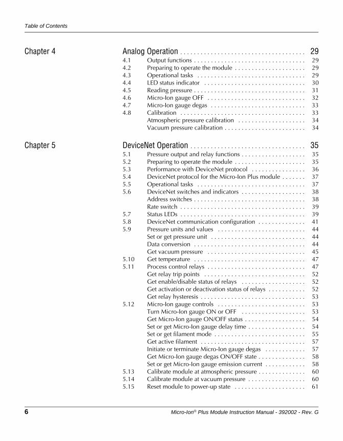
Table of Contents
6 Micro-Ion® Plus Module Instruction Manual - 392002 - Rev. G
Chapter 4 Analog Operation . . . . . . . . . . . . . . . . . . . . . . . . . . . . . . . . . . . . . 294.1 Output functions . . . . . . . . . . . . . . . . . . . . . . . . . . . . . . . . . 294.2 Preparing to operate the module . . . . . . . . . . . . . . . . . . . . . 294.3 Operational tasks . . . . . . . . . . . . . . . . . . . . . . . . . . . . . . . . 294.4 LED status indicator . . . . . . . . . . . . . . . . . . . . . . . . . . . . . . 304.5 Reading pressure . . . . . . . . . . . . . . . . . . . . . . . . . . . . . . . . . 314.6 Micro-Ion gauge OFF . . . . . . . . . . . . . . . . . . . . . . . . . . . . . 324.7 Micro-Ion gauge degas . . . . . . . . . . . . . . . . . . . . . . . . . . . . 334.8 Calibration . . . . . . . . . . . . . . . . . . . . . . . . . . . . . . . . . . . . . 33
Atmospheric pressure calibration . . . . . . . . . . . . . . . . . . . . 34Vacuum pressure calibration . . . . . . . . . . . . . . . . . . . . . . . . 34
Chapter 5 DeviceNet Operation . . . . . . . . . . . . . . . . . . . . . . . . . . . . . . . . . . 355.1 Pressure output and relay functions . . . . . . . . . . . . . . . . . . . 355.2 Preparing to operate the module . . . . . . . . . . . . . . . . . . . . . 355.3 Performance with DeviceNet protocol . . . . . . . . . . . . . . . . 365.4 DeviceNet protocol for the Micro-Ion Plus module . . . . . . . 375.5 Operational tasks . . . . . . . . . . . . . . . . . . . . . . . . . . . . . . . . 375.6 DeviceNet switches and indicators . . . . . . . . . . . . . . . . . . . 38
Address switches . . . . . . . . . . . . . . . . . . . . . . . . . . . . . . . . . 38Rate switch . . . . . . . . . . . . . . . . . . . . . . . . . . . . . . . . . . . . . 39
5.7 Status LEDs . . . . . . . . . . . . . . . . . . . . . . . . . . . . . . . . . . . . . 395.8 DeviceNet communication configuration . . . . . . . . . . . . . . 415.9 Pressure units and values . . . . . . . . . . . . . . . . . . . . . . . . . . 44
Set or get pressure unit . . . . . . . . . . . . . . . . . . . . . . . . . . . . 44Data conversion . . . . . . . . . . . . . . . . . . . . . . . . . . . . . . . . . 44Get vacuum pressure . . . . . . . . . . . . . . . . . . . . . . . . . . . . . 45
5.10 Get temperature . . . . . . . . . . . . . . . . . . . . . . . . . . . . . . . . . 475.11 Process control relays . . . . . . . . . . . . . . . . . . . . . . . . . . . . . 47
Get relay trip points . . . . . . . . . . . . . . . . . . . . . . . . . . . . . . 52Get enable/disable status of relays . . . . . . . . . . . . . . . . . . . 52Get activation or deactivation status of relays . . . . . . . . . . . 52Get relay hysteresis . . . . . . . . . . . . . . . . . . . . . . . . . . . . . . . 53
5.12 Micro-Ion gauge controls . . . . . . . . . . . . . . . . . . . . . . . . . . 53Turn Micro-Ion gauge ON or OFF . . . . . . . . . . . . . . . . . . . 53Get Micro-Ion gauge ON/OFF status . . . . . . . . . . . . . . . . . . 54Set or get Micro-Ion gauge delay time . . . . . . . . . . . . . . . . . 54Set or get filament mode . . . . . . . . . . . . . . . . . . . . . . . . . . . 55Get active filament . . . . . . . . . . . . . . . . . . . . . . . . . . . . . . . 57Initiate or terminate Micro-Ion gauge degas . . . . . . . . . . . . 57Get Micro-Ion gauge degas ON/OFF state . . . . . . . . . . . . . . 58Set or get Micro-Ion gauge emission current . . . . . . . . . . . . 58
5.13 Calibrate module at atmospheric pressure . . . . . . . . . . . . . . 605.14 Calibrate module at vacuum pressure . . . . . . . . . . . . . . . . . 605.15 Reset module to power-up state . . . . . . . . . . . . . . . . . . . . . 61
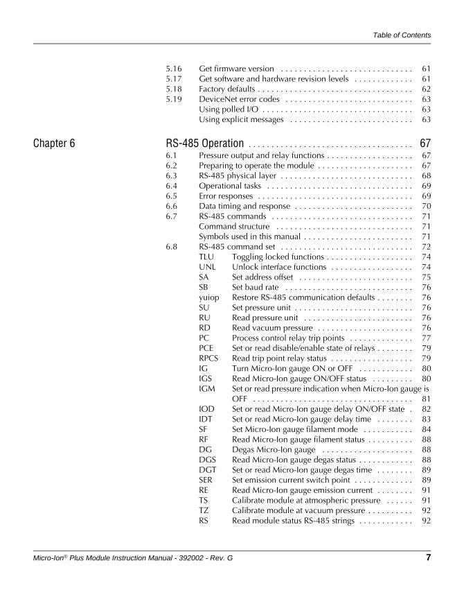
Table of Contents
Micro-Ion® Plus Module Instruction Manual - 392002 - Rev. G 7
5.16 Get firmware version . . . . . . . . . . . . . . . . . . . . . . . . . . . . . 615.17 Get software and hardware revision levels . . . . . . . . . . . . . 615.18 Factory defaults . . . . . . . . . . . . . . . . . . . . . . . . . . . . . . . . . . 625.19 DeviceNet error codes . . . . . . . . . . . . . . . . . . . . . . . . . . . . 63
Using polled I/O . . . . . . . . . . . . . . . . . . . . . . . . . . . . . . . . . 63Using explicit messages . . . . . . . . . . . . . . . . . . . . . . . . . . . 63
Chapter 6 RS-485 Operation . . . . . . . . . . . . . . . . . . . . . . . . . . . . . . . . . . . . 676.1 Pressure output and relay functions . . . . . . . . . . . . . . . . . . . 676.2 Preparing to operate the module . . . . . . . . . . . . . . . . . . . . . 676.3 RS-485 physical layer . . . . . . . . . . . . . . . . . . . . . . . . . . . . . 686.4 Operational tasks . . . . . . . . . . . . . . . . . . . . . . . . . . . . . . . . 696.5 Error responses . . . . . . . . . . . . . . . . . . . . . . . . . . . . . . . . . . 696.6 Data timing and response . . . . . . . . . . . . . . . . . . . . . . . . . . 706.7 RS-485 commands . . . . . . . . . . . . . . . . . . . . . . . . . . . . . . . 71
Command structure . . . . . . . . . . . . . . . . . . . . . . . . . . . . . . 71Symbols used in this manual . . . . . . . . . . . . . . . . . . . . . . . . 71
6.8 RS-485 command set . . . . . . . . . . . . . . . . . . . . . . . . . . . . . 72TLU Toggling locked functions . . . . . . . . . . . . . . . . . . . 74UNL Unlock interface functions . . . . . . . . . . . . . . . . . . 74SA Set address offset . . . . . . . . . . . . . . . . . . . . . . . . . 75SB Set baud rate . . . . . . . . . . . . . . . . . . . . . . . . . . . . 76yuiop Restore RS-485 communication defaults . . . . . . . . 76SU Set pressure unit . . . . . . . . . . . . . . . . . . . . . . . . . . 76RU Read pressure unit . . . . . . . . . . . . . . . . . . . . . . . . 76RD Read vacuum pressure . . . . . . . . . . . . . . . . . . . . . 76PC Process control relay trip points . . . . . . . . . . . . . . 77PCE Set or read disable/enable state of relays . . . . . . . . 79RPCS Read trip point relay status . . . . . . . . . . . . . . . . . . 79IG Turn Micro-Ion gauge ON or OFF . . . . . . . . . . . . 80IGS Read Micro-Ion gauge ON/OFF status . . . . . . . . . 80IGM Set or read pressure indication when Micro-Ion gauge is
OFF . . . . . . . . . . . . . . . . . . . . . . . . . . . . . . . . . . . 81IOD Set or read Micro-Ion gauge delay ON/OFF state . 82IDT Set or read Micro-Ion gauge delay time . . . . . . . . 83SF Set Micro-Ion gauge filament mode . . . . . . . . . . . 84RF Read Micro-Ion gauge filament status . . . . . . . . . . 88DG Degas Micro-Ion gauge . . . . . . . . . . . . . . . . . . . . 88DGS Read Micro-Ion gauge degas status . . . . . . . . . . . . 88DGT Set or read Micro-Ion gauge degas time . . . . . . . . 89SER Set emission current switch point . . . . . . . . . . . . . 89RE Read Micro-Ion gauge emission current . . . . . . . . 91TS Calibrate module at atmospheric pressure . . . . . . 91TZ Calibrate module at vacuum pressure . . . . . . . . . . 92RS Read module status RS-485 strings . . . . . . . . . . . . 92
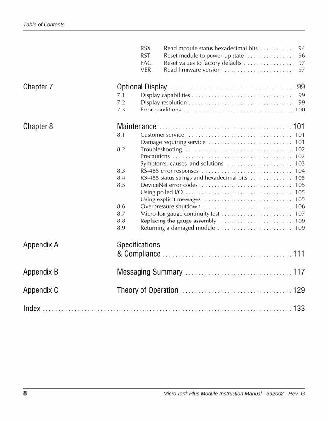
Table of Contents
8 Micro-Ion® Plus Module Instruction Manual - 392002 - Rev. G
RSX Read module status hexadecimal bits . . . . . . . . . . 94RST Reset module to power-up state . . . . . . . . . . . . . . 96FAC Reset values to factory defaults . . . . . . . . . . . . . . . 97VER Read firmware version . . . . . . . . . . . . . . . . . . . . . 97
Chapter 7 Optional Display . . . . . . . . . . . . . . . . . . . . . . . . . . . . . . . . . . . . . 997.1 Display capabilities . . . . . . . . . . . . . . . . . . . . . . . . . . . . . . . 997.2 Display resolution . . . . . . . . . . . . . . . . . . . . . . . . . . . . . . . . 997.3 Error conditions . . . . . . . . . . . . . . . . . . . . . . . . . . . . . . . . . 100
Chapter 8 Maintenance . . . . . . . . . . . . . . . . . . . . . . . . . . . . . . . . . . . . . . . . . 1018.1 Customer service . . . . . . . . . . . . . . . . . . . . . . . . . . . . . . . . 101
Damage requiring service . . . . . . . . . . . . . . . . . . . . . . . . . . 1018.2 Troubleshooting . . . . . . . . . . . . . . . . . . . . . . . . . . . . . . . . . 102
Precautions . . . . . . . . . . . . . . . . . . . . . . . . . . . . . . . . . . . . . 102Symptoms, causes, and solutions . . . . . . . . . . . . . . . . . . . . 103
8.3 RS-485 error responses . . . . . . . . . . . . . . . . . . . . . . . . . . . . 1048.4 RS-485 status strings and hexadecimal bits . . . . . . . . . . . . . 1058.5 DeviceNet error codes . . . . . . . . . . . . . . . . . . . . . . . . . . . . 105
Using polled I/O . . . . . . . . . . . . . . . . . . . . . . . . . . . . . . . . . 105Using explicit messages . . . . . . . . . . . . . . . . . . . . . . . . . . . 105
8.6 Overpressure shutdown . . . . . . . . . . . . . . . . . . . . . . . . . . . 1068.7 Micro-Ion gauge continuity test . . . . . . . . . . . . . . . . . . . . . . 1078.8 Replacing the gauge assembly . . . . . . . . . . . . . . . . . . . . . . 1098.9 Returning a damaged module . . . . . . . . . . . . . . . . . . . . . . . 109
Appendix A Specifications& Compliance . . . . . . . . . . . . . . . . . . . . . . . . . . . . . . . . . . . . . . . . 111
Appendix B Messaging Summary . . . . . . . . . . . . . . . . . . . . . . . . . . . . . . . . . 117
Appendix C Theory of Operation . . . . . . . . . . . . . . . . . . . . . . . . . . . . . . . . . . 129
Index . . . . . . . . . . . . . . . . . . . . . . . . . . . . . . . . . . . . . . . . . . . . . . . . . . . . . . . . . . . . . . . . . . . . . . . . . . . . . 133
Micro-Ion® Plus Module Instruction Manual - 392002 - Rev. G 9
Before You BeginInstallation
Operation OverviewAnalog Operation
Chapter 1 Before You Begin
1.1 About these instructions These instructions explain how to install, operate, and maintain the Granville-Phillips® Micro-Ion® Plus vacuum gauge module. The module contains a Micro-Ion ionization gauge and a Conductron® heat-loss sensor, which working in combination provide pressure measurement from 1 x 10⁻⁹ Torr (1 x 10⁻⁹ mbar, 1 x 10⁻⁷ Pa) to atmosphere.
The module has a DeviceNet interface, an RS-485 interface, and one analog output. The module may have no trip point relays, two trip point relays, or three trip point relays.
• This chapter explains caution and warning statements, which must be adhered to at all times; explains your responsibility for reading and following all instructions; defines the terms that are used throughout this instruction manual; and explains how to contact customer service.
• Chapter 2 explains how to install the module.
• Chapter 3 is an operational overview of the module.
• Chapter 4 explains analog output operation. The analog output does not operate independently but must operate with the DeviceNet or RS-485 interface.
• Chapter 5 explains DeviceNet interface operation.
• Chapter 6 explains RS-485 interface operation.
• Chapter 7 explains how to use the optional display.
• Chapter 8 explains troubleshooting; Micro-Ion gauge testing, removal and replacement; and module return procedures.
• Appendix A provides specifications for the module.
• Appendix B summarizes DeviceNet polled I/O and explicit messages.
• Appendix C explains how the Micro-Ion gauge and Conductron heat-loss sensor measure pressure.
1.2 Caution and warning statements
This manual contains caution and warning statements with which you must comply to prevent inaccurate measurement, property damage, or personal injury.
CAUTIONCaution statements alert you to hazards or unsafe practices that could result in inaccurate measurement, minor personal injury or property damage.Each caution statement explains what you must do to prevent or avoid the potential result of the specified hazard or unsafe practice.
Chapter 1
10 Micro-Ion® Plus Module Instruction Manual - 392002 - Rev. G
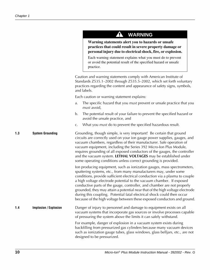
Caution and warning statements comply with American Institute of Standards Z535.1–2002 through Z535.5–2002, which set forth voluntary practices regarding the content and appearance of safety signs, symbols, and labels.
Each caution or warning statement explains:
a. The specific hazard that you must prevent or unsafe practice that you must avoid,
b. The potential result of your failure to prevent the specified hazard or avoid the unsafe practice, and
c. What you must do to prevent the specified hazardous result.
1.3 System Grounding Grounding, though simple, is very important! Be certain that ground circuits are correctly used on your ion gauge power supplies, gauges, and vacuum chambers, regardless of their manufacturer. Safe operation of vacuum equipment, including the Series 392 Micro-Ion Plus Module, requires grounding of all exposed conductors of the gauges, the controller and the vacuum system. LETHAL VOLTAGES may be established under some operating conditions unless correct grounding is provided.
Ion producing equipment, such as ionization gauges, mass spectrometers, sputtering systems, etc., from many manufacturers may, under some conditions, provide sufficient electrical conduction via a plasma to couple a high voltage electrode potential to the vacuum chamber. If exposed conductive parts of the gauge, controller, and chamber are not properly grounded, they may attain a potential near that of the high voltage electrode during this coupling. Potential fatal electrical shock could then occur because of the high voltage between these exposed conductors and ground.
1.4 Implosion / Explosion Danger of injury to personnel and damage to equipment exists on all vacuum systems that incorporate gas sources or involve processes capable of pressuring the system above the limits it can safely withstand.
For example, danger of explosion in a vacuum system exists during backfilling from pressurized gas cylinders because many vacuum devices such as ionization gauge tubes, glass windows, glass belljars, etc., are not designed to be pressurized.
WARNINGWarning statements alert you to hazards or unsafe practices that could result in severe property damage or personal injury due to electrical shock, fire, or explosion.
Each warning statement explains what you must do to prevent or avoid the potential result of the specified hazard or unsafe practice.
Before You Begin
Micro-Ion® Plus Module Instruction Manual - 392002 - Rev. G 11
Before You BeginInstallation
Operation OverviewAnalog Operation
Install suitable devices that will limit the pressure from external gas sources to the level that the vacuum system can safely withstand. In addition, install suitable pressure relief valves or rupture disks that will release pressure at a level considerably below that pressure which the system can safely withstand.
Suppliers of pressure relief valves and pressure relief disks are listed in Thomas Register under "Valves, Relief", and "Discs, Rupture".
Confirm that these safety devices are properly installed before installing the Series 392 Micro-Ion Plus Module. In addition, check that (1) the proper gas cylinders are installed, (2) gas cylinder valve positions are correct on manual systems, and (3) the automation is correct on automated systems.
1.5 Operation It is the installer's responsibility to ensure that the automatic signals provided by the process control module are always used in a safe manner.
Carefully check manual operation of the system and the setpoint programming before switching to automatic operation. Where an equipment malfunction could cause a hazardous situation, always provide for fail-safe operation. As an example, in an automatic backfill operation where a malfunction might cause high internal pressures, provide an appropriate pressure relief device.
1.6 Reading and following instructions
You must comply with all instructions while you are installing, operating, or maintaining the module. Failure to comply with the instructions violates standards of design, manufacture, and intended use of the module. MKS Instuments, Inc. / Granville-Phillips disclaim all liability for the customer's failure to comply with the instructions.
• Read instructions – Read all instructions before installing or operating the product.
• Follow instructions – Follow all installation, operating and maintenance instructions.
• Retain instructions – Retain the instructions for future reference.
• Heed warnings and cautions – Adhere to all warnings and caution statements on the product and in these instructions.
• Parts and accessories – Install only those replacement parts and accessories that are recommended by Granville-Phillips. Substitution of parts is hazardous.
Chapter 1
12 Micro-Ion® Plus Module Instruction Manual - 392002 - Rev. G
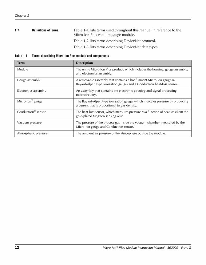
1.7 Definitions of terms Table 1-1 lists terms used throughout this manual in reference to the Micro-Ion Plus vacuum gauge module.
Table 1-2 lists terms describing DeviceNet protocol.
Table 1-3 lists terms describing DeviceNet data types.
Table 1-1 Terms describing Micro-Ion Plus module and components
Term Description
Module The entire Micro-Ion Plus product, which includes the housing, gauge assembly, and electronics assembly.
Gauge assembly A removable assembly that contains a hot filament Micro-Ion gauge (a Bayard-Alpert type ionization gauge) and a Conductron heat-loss sensor.
Electronics assembly An assembly that contains the electronic circuitry and signal processing microcircuitry.
Micro-Ion® gauge The Bayard-Alpert type ionization gauge, which indicates pressure by producing a current that is proportional to gas density.
Conductron® sensor The heat-loss sensor, which measures pressure as a function of heat loss from the gold-plated tungsten sensing wire.
Vacuum pressure The pressure of the process gas inside the vacuum chamber, measured by the Micro-Ion gauge and Conductron sensor.
Atmospheric pressure The ambient air pressure of the atmosphere outside the module.
Before You Begin
Micro-Ion® Plus Module Instruction Manual - 392002 - Rev. G 13
Before You BeginInstallation
Operation OverviewAnalog Operation
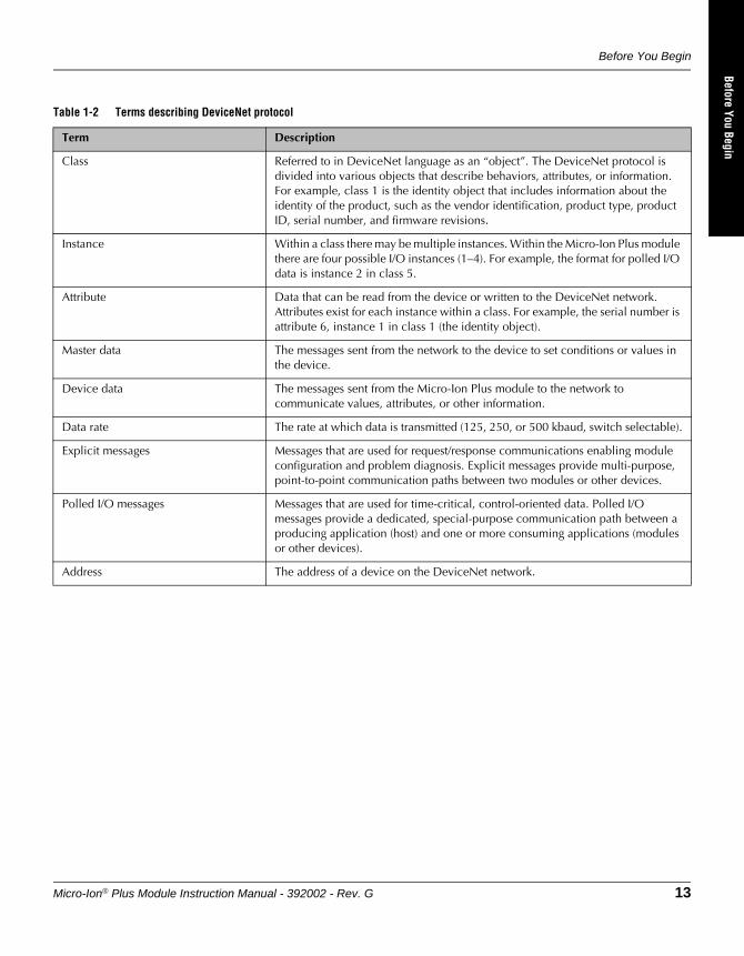
Table 1-2 Terms describing DeviceNet protocol
Term Description
Class Referred to in DeviceNet language as an “object”. The DeviceNet protocol is divided into various objects that describe behaviors, attributes, or information. For example, class 1 is the identity object that includes information about the identity of the product, such as the vendor identification, product type, product ID, serial number, and firmware revisions.
Instance Within a class there may be multiple instances. Within the Micro-Ion Plus module there are four possible I/O instances (1–4). For example, the format for polled I/O data is instance 2 in class 5.
Attribute Data that can be read from the device or written to the DeviceNet network. Attributes exist for each instance within a class. For example, the serial number is attribute 6, instance 1 in class 1 (the identity object).
Master data The messages sent from the network to the device to set conditions or values in the device.
Device data The messages sent from the Micro-Ion Plus module to the network to communicate values, attributes, or other information.
Data rate The rate at which data is transmitted (125, 250, or 500 kbaud, switch selectable).
Explicit messages Messages that are used for request/response communications enabling module configuration and problem diagnosis. Explicit messages provide multi-purpose, point-to-point communication paths between two modules or other devices.
Polled I/O messages Messages that are used for time-critical, control-oriented data. Polled I/O messages provide a dedicated, special-purpose communication path between a producing application (host) and one or more consuming applications (modules or other devices).
Address The address of a device on the DeviceNet network.
14 Micro-Ion® Plus Module Instruction Manual - 392002 - Rev. G
1.8 Customer service For Customer Service or Technical Support 24 hours per day, 7 days per week, every day of the year including holidays:
Phone: +1-800-227-8766 or +1-303-652-4691
Email: [email protected]
MKS, Granville-Phillips Division6450 Dry Creek ParkwayLongmont, CO 80503 USAPhone: 1-303-652-4691 or 1-800-776-6543 FAX: 1-303-652-2844
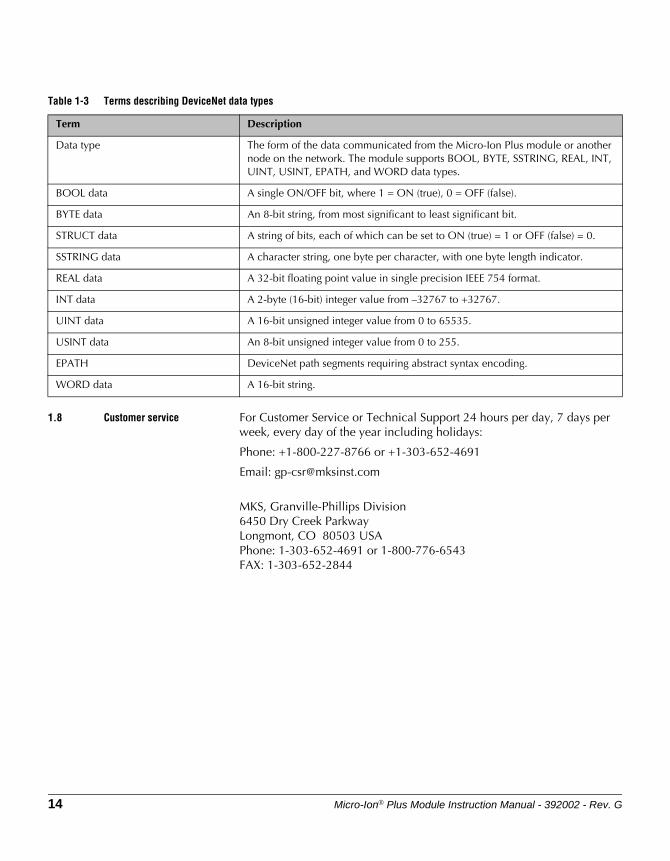
Table 1-3 Terms describing DeviceNet data types
Term Description
Data type The form of the data communicated from the Micro-Ion Plus module or another node on the network. The module supports BOOL, BYTE, SSTRING, REAL, INT, UINT, USINT, EPATH, and WORD data types.
BOOL data A single ON/OFF bit, where 1 = ON (true), 0 = OFF (false).
BYTE data An 8-bit string, from most significant to least significant bit.
STRUCT data A string of bits, each of which can be set to ON (true) = 1 or OFF (false) = 0.
SSTRING data A character string, one byte per character, with one byte length indicator.
REAL data A 32-bit floating point value in single precision IEEE 754 format.
INT data A 2-byte (16-bit) integer value from –32767 to +32767.
UINT data A 16-bit unsigned integer value from 0 to 65535.
USINT data An 8-bit unsigned integer value from 0 to 255.
EPATH DeviceNet path segments requiring abstract syntax encoding.
WORD data A 16-bit string.
Micro-Ion® Plus Module Instruction Manual - 392002 - Rev. G 15
Before You BeginInstallation
Operation OverviewAnalog Operation
Chapter 2 Installation
2.1 Module components The Micro-Ion Plus module contains a Micro-Ion gauge (Bayard-Alpert type ionization gauge) and a Conductron heat-loss sensor.
2.2 Pressure relief devices Before you install the module, you should install appropriate pressure relief devices in the vacuum system.
Granville-Phillips does not supply pressure relief valves or rupture disks. Suppliers of pressure relief valves and rupture disks are listed in the Thomas Register under “Valves, Relief” and “Discs, Rupture.”
WARNINGUsing the module to measure the pressure of flammable or explosive gases can cause a fire or explosion resulting in severe property damage or personal injury.
Do not use the module to measure the pressure of flammable or explosive gases.
WARNINGExposing the module to moisture can cause fire or electrical shock resulting in severe property damage or personal injury.
To avoid exposing the module to moisture, install the module in an indoor environment. Do not install the module in any outdoor environment.
CAUTIONOperating the module above 1000 Torr (1333 mbar, 133 kPa) true pressure could cause pressure measurement error or product failure.To avoid measurement error or product failure due to overpressurization, install pressure relief valves or rupture disks in the system if pressure substantially exceeds 1000 Torr (1333 mbar, 133 kPa).
Chapter 2
16 Micro-Ion® Plus Module Instruction Manual - 392002 - Rev. G
2.3 Installation procedure The module installation procedure includes the following steps:
1. Locate the module.
2. Attach the module vacuum chamber fitting to its mating fitting on the vacuum chamber.
3. Assemble and connect the module wiring.
4. Calibrate the module at atmospheric pressure.
This chapter also explains what to do if radio frequency interference (RFI) disrupts operation of RS-485 version of the module.
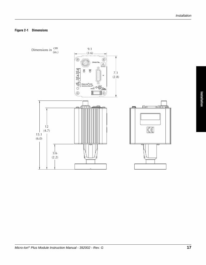
Step 1 Locate the module
To locate the module, refer to Figure 2-1 and follow the guidelines below.
• For greatest accuracy and repeatability, locate the module in a stable, room-temperature environment. Ambient temperature should never exceed 40 °C (104 °F) operating, non-condensing, or 85 °C (185 °F) non-operating. Bakeout temperature with the electronics removed from the module is 105 °C (221 °F).
• Locate the module away from internal and external heat sources and in an area where ambient temperature remains reasonably constant.
• Do not locate the module near the pump, where gauge pressure might be lower than system vacuum pressure.
• Do not locate the module near a gas inlet or other source of contamination, where inflow of gas or particulates causes atmospheric pressure to be higher than system atmosphere.
• Do not locate the module where it will be exposed to corrosive gases such as mercury vapor or fluorine.
Installation
Micro-Ion® Plus Module Instruction Manual - 392002 - Rev. G 17
Before You BeginInstallation
Operation OverviewAnalog Operation
Figure 2-1 Dimensions
7.1(2.8)
12(4.7)
Dimensions in cm(in.)
5.6(2.2)
9.1(3.6)
15.1(6.0)
Chapter 2
18 Micro-Ion® Plus Module Instruction Manual - 392002 - Rev. G
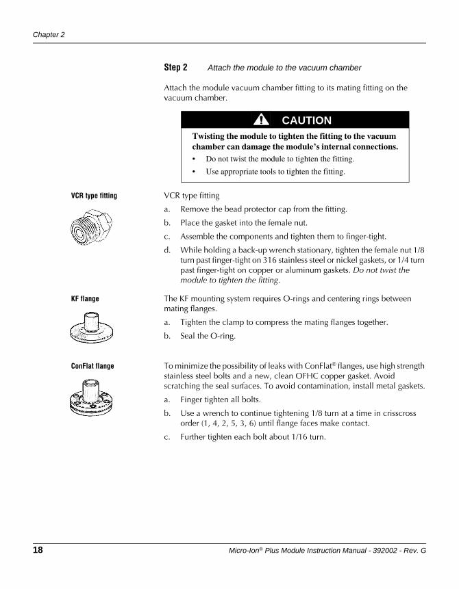
Step 2 Attach the module to the vacuum chamber
Attach the module vacuum chamber fitting to its mating fitting on the vacuum chamber.
VCR type fitting VCR type fitting
a. Remove the bead protector cap from the fitting.
b. Place the gasket into the female nut.
c. Assemble the components and tighten them to finger-tight.
d. While holding a back-up wrench stationary, tighten the female nut 1/8 turn past finger-tight on 316 stainless steel or nickel gaskets, or 1/4 turn past finger-tight on copper or aluminum gaskets. Do not twist the module to tighten the fitting.
KF flange The KF mounting system requires O-rings and centering rings between mating flanges.
a. Tighten the clamp to compress the mating flanges together.
b. Seal the O-ring.
ConFlat flange To minimize the possibility of leaks with ConFlat® flanges, use high strength stainless steel bolts and a new, clean OFHC copper gasket. Avoid scratching the seal surfaces. To avoid contamination, install metal gaskets.
a. Finger tighten all bolts.
b. Use a wrench to continue tightening 1/8 turn at a time in crisscross order (1, 4, 2, 5, 3, 6) until flange faces make contact.
c. Further tighten each bolt about 1/16 turn.
CAUTIONTwisting the module to tighten the fitting to the vacuum chamber can damage the module’s internal connections.• Do not twist the module to tighten the fitting.
• Use appropriate tools to tighten the fitting.
Installation
Micro-Ion® Plus Module Instruction Manual - 392002 - Rev. G 19
Before You BeginInstallation
Operation OverviewAnalog Operation
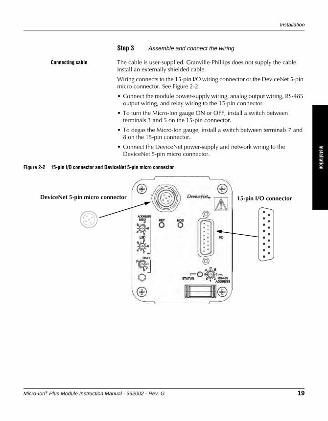
Step 3 Assemble and connect the wiring
Connecting cable The cable is user-supplied. Granville-Phillips does not supply the cable. Install an externally shielded cable.
Wiring connects to the 15-pin I/O wiring connector or the DeviceNet 5-pin micro connector. See Figure 2-2.
• Connect the module power-supply wiring, analog output wiring, RS-485 output wiring, and relay wiring to the 15-pin connector.
• To turn the Micro-Ion gauge ON or OFF, install a switch between terminals 3 and 5 on the 15-pin connector.
• To degas the Micro-Ion gauge, install a switch between terminals 7 and 8 on the 15-pin connector.
• Connect the DeviceNet power-supply and network wiring to the DeviceNet 5-pin micro connector.
Figure 2-2 15-pin I/O connector and DeviceNet 5-pin micro connector
DeviceNet 5-pin micro connector 15-pin I/O connector
Chapter 2
20 Micro-Ion® Plus Module Instruction Manual - 392002 - Rev. G
CE Mark compliance For CE mark compliance, use the following cable types (or equivalent):
Cable to 15-pin I/O connector
For cable that connects to the 15-pin I/O connector, install shielded cable with aluminum jacket and a tinned copper braid with a minimum of 65% coverage.
On the module end of the cable, install a metal housing so the shield is continuous from the cable to the gauge housing. Do not ground the shield at the receiver or output device.
Acceptable raw cable parts:
• Belden cable 9947.
• Alpha cable 5110/15C SL005.
Acceptable connectors:
• Tyco series ADK for standard 15-pin subminiature-D connectors.
• Norcomp type 979-015-030-121.
DeviceNet cable For the DeviceNet cable, install raw cable that has a braided shield over the aluminum foil-shielded signal and power wires.
On the module end of the cable, install a metal housing, so the shield is continuous from the cable to the gauge housing. Do not ground the shield at the receiver or output device.
• Acceptable raw cable is DeviceNet shielded cable type 578 from Turck.
• Acceptable connector is CM 8151-0 metal connector from Turck.
Module power supply Connect the module power supply to terminals 5 and 8 on the 15-pin I/O wiring connector.
• Terminal 5 (ground) is negative (–).
• Terminal 8 (input) is positive (+).
The module requires 24 Vdc ±15% (1.5 A current at 20.4 V), 3.0 A current at 30 W peak. Inrush current can momentarily exceed the 3.0 A peak.
Typical module operating power is 18 W for 4 mA emission when the Micro-Ion gauge is ON.
Power inputs are reverse-bias protected.
The Micro-Ion gauge will not activate and an emission error will occur if insufficient power is supplied during Micro-Ion gauge activation.
Installation
Micro-Ion® Plus Module Instruction Manual - 392002 - Rev. G 21
Before You BeginInstallation
Operation OverviewAnalog Operation
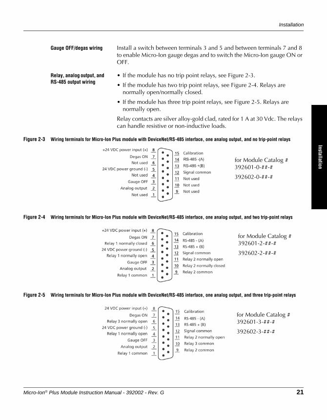
Gauge OFF/degas wiring Install a switch between terminals 3 and 5 and between terminals 7 and 8 to enable Micro-Ion gauge degas and to switch the Micro-Ion gauge ON or OFF.
Relay, analog output, and RS-485 output wiring
• If the module has no trip point relays, see Figure 2-3.
• If the module has two trip point relays, see Figure 2-4. Relays are normally open/normally closed.
• If the module has three trip point relays, see Figure 2-5. Relays are normally open.
Relay contacts are silver alloy-gold clad, rated for 1 A at 30 Vdc. The relays can handle resistive or non-inductive loads.
Figure 2-3 Wiring terminals for Micro-Ion Plus module with DeviceNet/RS-485 interface, one analog output, and no trip-point relays
Figure 2-4 Wiring terminals for Micro-Ion Plus module with DeviceNet/RS-485 interface, one analog output, and two trip-point relays
Figure 2-5 Wiring terminals for Micro-Ion Plus module with DeviceNet/RS-485 interface, one analog output, and three trip-point relays
for Module Catalog # 392601-0-##-#
392602-0-##-#
for Module Catalog # 392601-2-##-#
392602-2-##-#
for Module Catalog # 392601-3-##-#
392602-3-##-#
Chapter 2
22 Micro-Ion® Plus Module Instruction Manual - 392002 - Rev. G
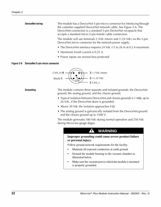
DeviceNet wiring The module has a DeviceNet 5-pin micro connector for interfacing through the customer supplied DeviceNet network cable. See Figure 2-6. The DeviceNet connection is a standard 5-pin DeviceNet receptacle that accepts a standard micro 5-pin female cable connection.
The module will use terminals 2 (Vdc return) and 3 (24 Vdc) on the 5-pin DeviceNet micro connector for the network power supply.
• The DeviceNet interface requires 24 Vdc (11 to 26.4) at 0.2 A maximum.
• Maximum inrush current is 0.25 A.
• Power inputs are reverse-bias protected.
Figure 2-6 DeviceNet 5-pin micro connector
Grounding The module contains three separate and isolated grounds: the DeviceNet ground, the analog ground, and the chassis ground.
• Typical isolation between DeviceNet and chassis grounds is 1 MΩ, up to 26 Vdc, if the DeviceNet drain is grounded.
• Above 30 Vdc the isolation approaches 0 Ω.
• The analog ground is galvanically isolated from the DeviceNet ground and the chassis ground up to 1500 V.
The module generates 180 Vdc during normal operation and 250 Vdc during Micro-Ion gauge degas.
CAN_H 4
Shield 1
3 (–) Vdc return
2 (+) 24 Vdc
5 CAN_L
WARNINGImproper grounding could cause severe product failure or personal injury.
Follow ground network requirements for the facility.
• Maintain all exposed conductors at earth ground.
• Ground the module housing to the vacuum chamber as illustrated below.
• Make sure the vacuum port to which the module is mounted is properly grounded.
Installation
Micro-Ion® Plus Module Instruction Manual - 392002 - Rev. G 23
Before You BeginInstallation
Operation OverviewAnalog Operation
DeviceNet grounding The DeviceNet wiring will be properly grounded via the DeviceNet 5-pin micro connector.
Chassis ground If the module has a VCR type fitting or ConFlat flange, the module chassis will be properly grounded via the vacuum chamber connection.
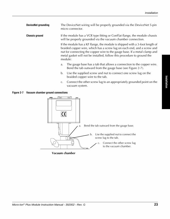
If the module has a KF flange, the module is shipped with a 3-foot length of braided copper wire, which has a screw lug on each end, and a screw and nut for connecting the copper wire to the gauge base. If a metal clamp and metal gasket will not be installed, follow this procedure to ground the module:
a. The gauge base has a tab that allows a connection to the copper wire. Bend the tab outward from the gauge base (see Figure 2-7).
b. Use the supplied screw and nut to connect one screw lug on the braided copper wire to the tab.
c. Connect the other screw lug to an appropriately grounded point on the vacuum system.
Figure 2-7 Vacuum chamber ground connections
a. Bend the tab outward from the gauge base.
Vacuum chamber
b. Use the supplied nut to connect the screw lug to the tab.
c. Connect the other screw lug to the vacuum chamber.
Chapter 2
24 Micro-Ion® Plus Module Instruction Manual - 392002 - Rev. G
Step 4 Calibrate the module at atmospheric pressure
• To calibrate the module at atmospheric pressure using a momentary switch installed between pins 15 and 5 on the 15-pin connector, see page 34.
• To calibrate the module at atmospheric pressure using an RS-485 command, see page 91.
• To calibrate the module at atmospheric pressure using DeviceNet explicit messaging, see page 60.
Atmospheric pressure calibration is performed at the factory before the module is shipped. The module will not operate properly unless you reset the atmospheric pressure calibration at the ambient operating pressure.
2.4 Eliminating radio frequency interference
The module has been tested and found to comply with U.S. Federal Communications Commission (FCC) limits for a Class A digital device, pursuant to Part 15 of the FCC rules. These limits provide reasonable protection against harmful interference when the module operates in a commercial environment.
The module generates and can radiate radio frequency energy. If not installed and used in accordance with the instructions in this manual, the module may cause harmful interference to other electrical equipment.
Micro-Ion® Plus Module Instruction Manual - 392002 - Rev. G 25
Before You BeginInstallation
Operation OverviewAnalog Operation
Before You Begin
Chapter 3 Operation Overview
3.1 Interface, outputs, and relays
The module has a DeviceNet interface, an RS-485 interface, and one analog output. The module may have no trip point relays, two trip point relays, or three trip point relays.
3.2 Analog operation Table 3-1 lists tasks that may be performed using the analog output. The output represents vacuum pressure. Using the analog output requires installing switches on the 15-pin sub-miniature D connector. The switches enable you to initiate or terminate the Micro-Ion gauge degas, calibrate the module at atmospheric pressure, or calibrate the module at vacuum pressure.
The analog output does not operate independently but must operate with the DeviceNet or RS-485 interface.
3.3 DeviceNet operation • Table 3-2 lists tasks that may be performed using DeviceNet polled I/O.
• Table 3-3 lists tasks that may be performed using DeviceNet explicit messages.
• For a complete list of DeviceNet messages used by the module, see Appendix B.
Table 3-1 Tasks and page references for operation using the 15-pin sub-miniature D connector
Task Instructions:
Read vacuum pressure Page 31
Turn the Micro-Ion gauge OFF Page 32
Initiate or terminate Micro-Ion gauge degas Page 33
Calibrate module at atmospheric pressure Page 34
Calibrate module at vacuum pressure Page 34
Table 3-2 Tasks and page references for DeviceNet polled I/O
Task Instructions:
Read vacuum pressure Page 45
Turn the Micro-Ion gauge OFF Page 53
Initiate or terminate Micro-Ion gauge degas Page 57
Chapter 3
26 Micro-Ion® Plus Module Instruction Manual - 392002 - Rev. G
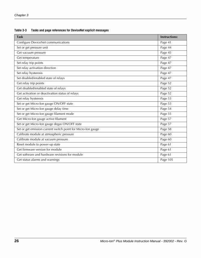
Table 3-3 Tasks and page references for DeviceNet explicit messages
Task Instructions:
Configure DeviceNet communications Page 41
Set or get pressure unit Page 44
Get vacuum pressure Page 45
Get temperature Page 47
Set relay trip points Page 47
Set relay activation direction Page 47
Set relay hysteresis Page 47
Set disabled/enabled state of relays Page 47
Get relay trip points Page 52
Get disabled/enabled state of relays Page 52
Get activation or deactivation status of relays Page 52
Get relay hysteresis Page 53
Set or get Micro-Ion gauge ON/OFF state Page 53
Set or get Micro-Ion gauge delay time Page 54
Set or get Micro-Ion gauge filament mode Page 55
Get Micro-Ion gauge active filament Page 57
Set or get Micro-Ion gauge degas ON/OFF state Page 57
Set or get emission current switch point for Micro-Ion gauge Page 58
Calibrate module at atmospheric pressure Page 60
Calibrate module at vacuum pressure Page 60
Reset module to power-up state Page 61
Get firmware version for module Page 61
Get software and hardware revisions for module Page 61
Get status alarms and warnings Page 105
Operation Overview
Micro-Ion® Plus Module Instruction Manual - 392002 - Rev. G 27
Before You BeginInstallation
Operation OverviewAnalog Operation
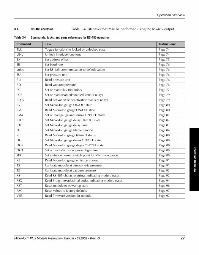
3.4 RS-485 operation Table 3-4 lists tasks that may be performed using the RS-485 output.
Table 3-4 Commands, tasks, and page references for RS-485 operation
Command Task Instructions:
TLU Toggle functions to locked or unlocked state Page 74
UNL Unlock interface functions Page 74
SA Set address offset Page 75
SB Set baud rate Page 76
yuiop Set RS-485 communication to default values Page 76
SU Set pressure unit Page 76
RU Read pressure unit Page 76
RD Read vacuum pressure Page 76
PC Set or read relay trip points Page 77
PCE Set or read disabled/enabled state of relays Page 79
RPCS Read activation or deactivation status of relays Page 79
IG Set Micro-Ion gauge ON/OFF state Page 80
IGS Read Micro-Ion gauge ON/OFF state Page 80
IGM Set or read gauge and sensor ON/OFF mode Page 81
IOD Set Micro-Ion gauge delay ON/OFF state Page 82
IDT Set Micro-Ion gauge delay time Page 83
SF Set Micro-Ion gauge filament mode Page 84
RF Read Micro-Ion gauge filament status Page 88
DG Set Micro-Ion gauge degas ON/OFF state Page 88
DGS Read Micro-Ion gauge degas ON/OFF state Page 88
DGT Set or read Micro-Ion gauge degas time Page 89
SER Set emission current switch point for Micro-Ion gauge Page 89
RE Read Micro-Ion gauge emission current Page 91
TS Calibrate module at atmospheric pressure Page 91
TZ Calibrate module at vacuum pressure Page 92
RS Read RS-485 character strings indicating module status Page 92
RSX Read 8-digit hexadecimal codes indicating module status Page 94
RST Reset module to power-up state Page 96
FAC Reset values to factory defaults Page 97
VER Read firmware version for module Page 97
Chapter 3
28 Micro-Ion® Plus Module Instruction Manual - 392002 - Rev. G
3.5 Automatic filament selection
As the vacuum system pumps down from atmosphere, the Conductron sensor measures pressure until a sufficiently low pressure level is achieved, then automatically turns ON the Micro-Ion gauge. The filaments in the Micro-Ion gauge can burn out if they turn ON at a pressure that is too high.
Tungsten filaments are more likely than yttria-coated iridium filaments to burn out if they turn ON at a pressure that is too high. To reduce the risk of burnout, the default behavior of Micro-Ion gauge depends on the filament material.
If a rapid increase in pressure from high vacuum levels to pressures of 1 Torr (1.33 mbar, 133 Pa) or higher pressure occurs, tungsten filaments are almost certain to burn out. This risk is not unique to the Micro-Ion gauge and exists for all ion gauges containing tungsten filaments.
• At startup, the module software detects the filament material and sets the behavior of the Micro-Ion gauge accordingly, as listed in Table 3-5.
• If the gauge assembly is replaced, the module software automatically sets the behavior of the Micro-Ion gauge according to the filament material.
• For RS-485 communications, you can use the IOD, IDT, and SF commands to change the behavior of the Micro-Ion gauge. See pages 84–88.
• For DeviceNet communications, you can use explicit messages to change the behavior of the Micro-Ion gauge. See pages 55–56.
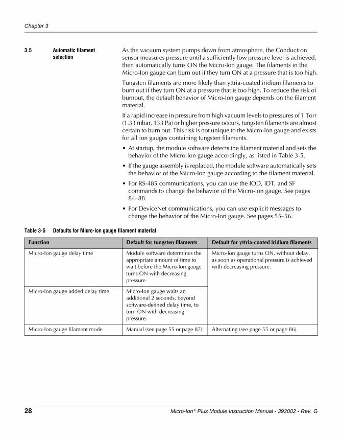
Table 3-5 Defaults for Micro-Ion gauge filament material
Function Default for tungsten filaments Default for yttria-coated iridium filaments
Micro-Ion gauge delay time Module software determines the appropriate amount of time to wait before the Micro-Ion gauge turns ON with decreasing pressure
Micro-Ion gauge turns ON, without delay, as soon as operational pressure is achieved with decreasing pressure.
Micro-Ion gauge added delay time Micro-Ion gauge waits an additional 2 seconds, beyond software-defined delay time, to turn ON with decreasing pressure.
Micro-Ion gauge filament mode Manual (see page 55 or page 87). Alternating (see page 55 or page 86).
Micro-Ion® Plus Module Instruction Manual - 392002 - Rev. G 29
Before You BeginInstallation
Operation OverviewAnalog Operation
Chapter 4 Analog Operation
4.1 Output functions The module has a DeviceNet interface, an RS-485 interface, and one analog output. The analog output represents vacuum pressure.
You may use the analog output wiring and switches connected to the pins on the 15-pin sub-miniature D connector to read vacuum pressure and operate the module.
The analog output does not operate independently but must operate with the DeviceNet or RS-485 interface.
4.2 Preparing to operate the module
Before putting the module into operation, you must perform the following procedures:
1. Install the module in accordance with the instructions on pages 15–24.
2. Develop a logic diagram of the process control function.
3. Develop a circuit schematic that specifies exactly how each piece of system hardware will connect to the module relays.
4. Attach a copy of the process control circuit diagram to this manual for future reference and troubleshooting.
If you need application assistance, phone a Granville-Phillips application engineer at 1-303-652-4400 or 1-800-776-6543, or email [email protected].
4.3 Operational tasks Once the module is operating, you may perform the tasks listed in Table 3-1 on page 25.
WARNINGUsing the module to measure the pressure of flammable or explosive gases can cause a fire or explosion resulting in severe property damage, personal injury, or death.
Do not use the module to measure the pressure of flammable or explosive gases.
Chapter 4
30 Micro-Ion® Plus Module Instruction Manual - 392002 - Rev. G
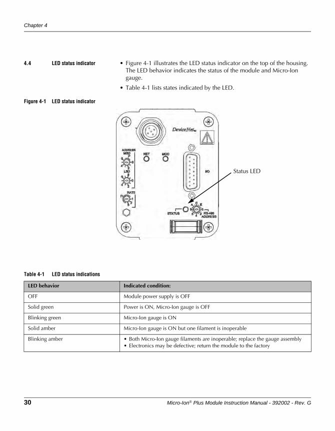
4.4 LED status indicator • Figure 4-1 illustrates the LED status indicator on the top of the housing. The LED behavior indicates the status of the module and Micro-Ion gauge.
• Table 4-1 lists states indicated by the LED.
Figure 4-1 LED status indicator
Status LED
Table 4-1 LED status indications
LED behavior Indicated condition:
OFF Module power supply is OFF
Solid green Power is ON, Micro-Ion gauge is OFF
Blinking green Micro-Ion gauge is ON
Solid amber Micro-Ion gauge is ON but one filament is inoperable
Blinking amber • Both Micro-Ion gauge filaments are inoperable; replace the gauge assembly• Electronics may be defective; return the module to the factory
Analog Operation
Micro-Ion® Plus Module Instruction Manual - 392002 - Rev. G 31
Before You BeginInstallation
Operation OverviewAnalog Operation
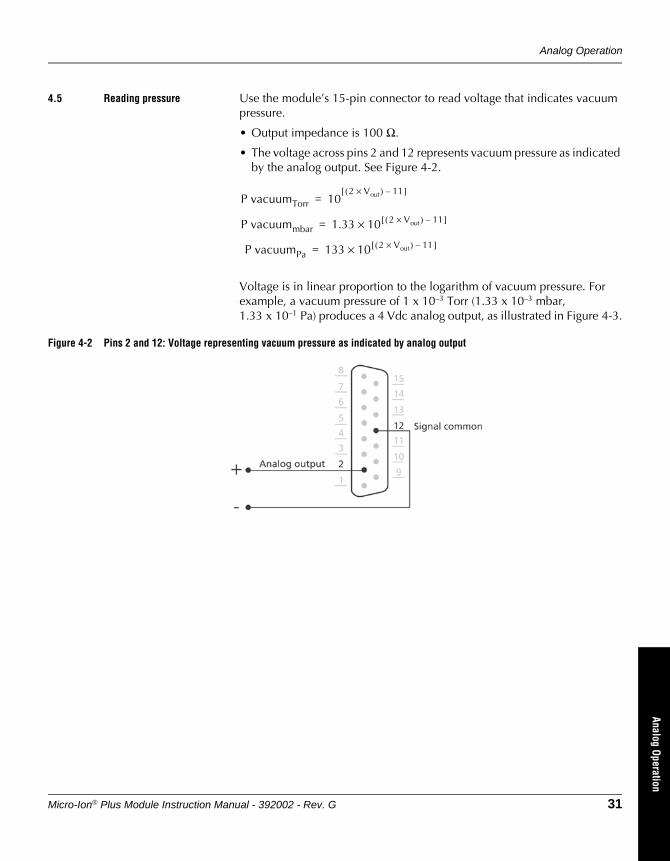
4.5 Reading pressure Use the module’s 15-pin connector to read voltage that indicates vacuum pressure.
• Output impedance is 100 Ω.
• The voltage across pins 2 and 12 represents vacuum pressure as indicated by the analog output. See Figure 4-2.
Voltage is in linear proportion to the logarithm of vacuum pressure. For example, a vacuum pressure of 1 x 10⁻³ Torr (1.33 x 10⁻³ mbar, 1.33 x 10⁻¹ Pa) produces a 4 Vdc analog output, as illustrated in Figure 4-3.
Figure 4-2 Pins 2 and 12: Voltage representing vacuum pressure as indicated by analog output
P vacuumTorr 102 Vout×( ) 11–[ ]
=
P vacuummbar 1.33 10 2 Vout×( ) 11–[ ]×=
P vacuumPa 133 10 2 Vout×( ) 11–[ ]×=
Chapter 4
32 Micro-Ion® Plus Module Instruction Manual - 392002 - Rev. G
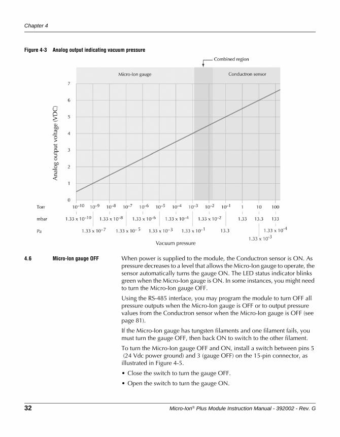
Figure 4-3 Analog output indicating vacuum pressure
4.6 Micro-Ion gauge OFF When power is supplied to the module, the Conductron sensor is ON. As pressure decreases to a level that allows the Micro-Ion gauge to operate, the sensor automatically turns the gauge ON. The LED status indicator blinks green when the Micro-Ion gauge is ON. In some instances, you might need to turn the Micro-Ion gauge OFF.
Using the RS-485 interface, you may program the module to turn OFF all pressure outputs when the Micro-Ion gauge is OFF or to output pressure values from the Conductron sensor when the Micro-Ion gauge is OFF (see page 81).
If the Micro-Ion gauge has tungsten filaments and one filament fails, you must turn the gauge OFF, then back ON to switch to the other filament.
To turn the Micro-Ion gauge OFF and ON, install a switch between pins 5 (24 Vdc power ground) and 3 (gauge OFF) on the 15-pin connector, as
illustrated in Figure 4-5.
• Close the switch to turn the gauge OFF.
• Open the switch to turn the gauge ON.

Analog Operation
Micro-Ion® Plus Module Instruction Manual - 392002 - Rev. G 33
Before You BeginInstallation
Operation OverviewAnalog Operation
Figure 4-4 Pins 5 and 3: Switch for Micro-Ion gauge OFF
4.7 Micro-Ion gauge degas To enable initiation and termination of the degas cycle for the Micro-Ion gauge, install a switch between pins 8 (24 Vdc power input) and 7 (degas ON) on the 15-pin connector, as illustrated in Figure 4-4.
• Close the switch between pins 8 and 7 to initiate the degas cycle. After initiation, the degas cycle continues for two minutes.
• The degas cycle ends immediately if you open the switch.
• During degas the module continues to output a pressure signal, but the indicated value may be affected by the degas function and indicate a less accurate pressure.
Figure 4-5 Pins 8 and 7: Switch for Micro-Ion gauge degas ON
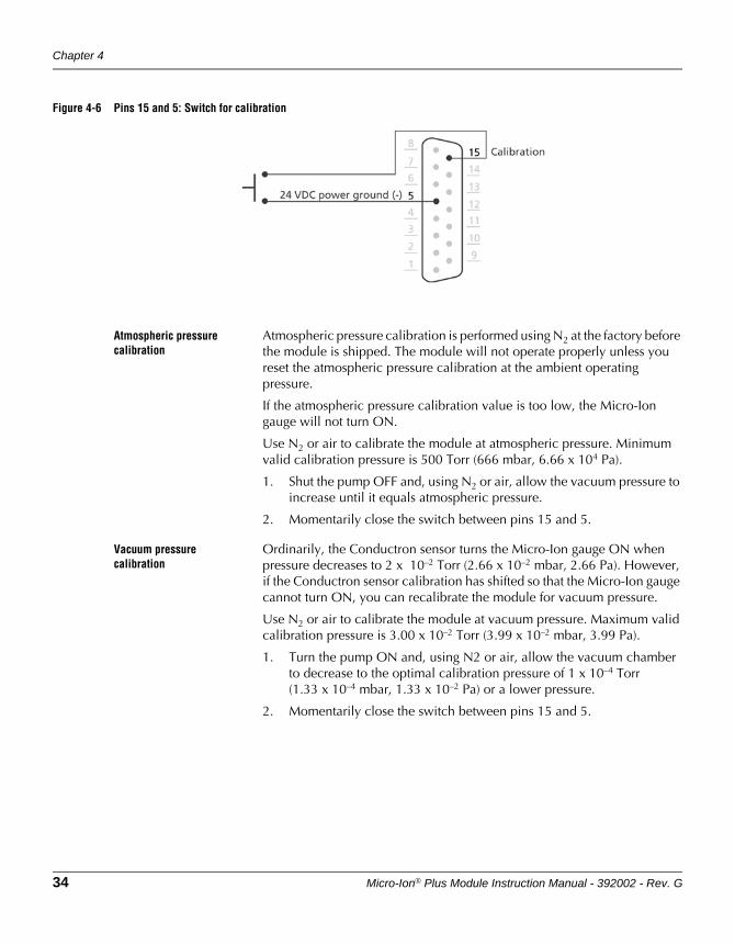
4.8 Calibration You may install a momentary contact switch between pins 15 (calibration) and 5 (24 Vdc power ground) to enable calibration at atmospheric or vacuum pressure. See Figure 4-6.
Chapter 4
34 Micro-Ion® Plus Module Instruction Manual - 392002 - Rev. G
Figure 4-6 Pins 15 and 5: Switch for calibration
Atmospheric pressure calibration
Atmospheric pressure calibration is performed using N2 at the factory before the module is shipped. The module will not operate properly unless you reset the atmospheric pressure calibration at the ambient operating pressure.
If the atmospheric pressure calibration value is too low, the Micro-Ion gauge will not turn ON.
Use N2 or air to calibrate the module at atmospheric pressure. Minimum valid calibration pressure is 500 Torr (666 mbar, 6.66 x 10⁴ Pa).
1. Shut the pump OFF and, using N2 or air, allow the vacuum pressure to increase until it equals atmospheric pressure.
2. Momentarily close the switch between pins 15 and 5.
Vacuum pressure calibration
Ordinarily, the Conductron sensor turns the Micro-Ion gauge ON when pressure decreases to 2 x 10⁻² Torr (2.66 x 10⁻² mbar, 2.66 Pa). However, if the Conductron sensor calibration has shifted so that the Micro-Ion gauge cannot turn ON, you can recalibrate the module for vacuum pressure.
Use N2 or air to calibrate the module at vacuum pressure. Maximum valid calibration pressure is 3.00 x 10⁻² Torr (3.99 x 10⁻² mbar, 3.99 Pa).
1. Turn the pump ON and, using N2 or air, allow the vacuum chamber to decrease to the optimal calibration pressure of 1 x 10⁻⁴ Torr (1.33 x 10⁻⁴ mbar, 1.33 x 10⁻² Pa) or a lower pressure.
2. Momentarily close the switch between pins 15 and 5.
Micro-Ion® Plus Module Instruction Manual - 392002 - Rev. G 35
DeviceNet OperationRS-485 Operation
Optional DisplayM
aintenance
Chapter 5 DeviceNet Operation
5.1 Pressure output and relay functions
The module has a DeviceNet interface, an RS-485 interface, and one analog output.
• The analog output represents vacuum chamber pressure.
• The module may have no trip point relays, two trip point relays, or three trip point relays. The relays represent vacuum pressure.
You may use polled I/O or explicit messages to read vacuum pressure and operate the module.
5.2 Preparing to operatethe module
Before putting the module into operation, you must perform the following procedures:
1. Install the module in accordance with the instructions on pages 15–24.
2. Develop a logic diagram of the process control function.
3. Develop a circuit schematic that specifies exactly how each piece of system hardware will connect to the module relays.
4. Attach a copy of the process control circuit diagram to this manual for future reference and troubleshooting.
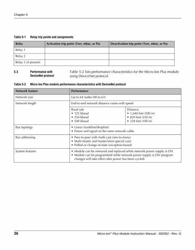
5. If the module has two or three trip point relays, use Table 5-1 to record the proposed activation and deactivation trip points (in Torr, mbar, or pascal) and assignments for each relay.
If you need application assistance, phone a Granville-Phillips application engineer:
• Phone 1-303-652-4400 or 1-800-776-6543
• Email: [email protected]
WARNINGUsing the module to measure the pressure of flammable or explosive gases can cause a fire or explosion resulting in severe property damage, personal injury, or death.
Do not use the module to measure the pressure of flammable or explosive gases.
Chapter 5
36 Micro-Ion® Plus Module Instruction Manual - 392002 - Rev. G
5.3 Performance with DeviceNet protocol
Table 5-2 lists performance characteristics for the Micro-Ion Plus module using DeviceNet protocol.
Table 5-1 Relay trip points and assignments
Relay Activation trip point (Torr, mbar, or Pa) Deactivation trip point (Torr, mbar, or Pa)
Relay 1
Relay 2
Relay 3 (if present)
Table 5-2 Micro-Ion Plus module performance characteristics with DeviceNet protocol
Network feature Performance
Network size Up to 64 nodes (00 to 63)
Network length End-to-end network distance varies with speed
Baud rate• 125 kbaud• 250 kbaud• 500 kbaud
Distance• 1,640 feet (500 m)• 820 feet (250 m)• 328 feet (100 m)
Bus topology • Linear (trunkline/dropline)• Power and signal on the same network cable
Bus addressing • Peer-to-peer with multi-cast (one-to-many)• Multi-master and master/slave special case• Polled or change-of-state (exception-based)
System features • Module can be removed and replaced while network power supply is ON• Module can be programmed while network power supply is ON (program
changes will take effect after power has been cycled)
DeviceNet Operation
Micro-Ion® Plus Module Instruction Manual - 392002 - Rev. G 37
DeviceNet OperationRS-485 Operation
Optional DisplayM
aintenance
5.4 DeviceNet protocol for the Micro-Ion Plus module
The Micro-Ion Plus module is based on the Open DeviceNet Vendors Association (ODVA) and S-Analog Sensor Object Class Subclass 01 (Instance Selector) standards. The Micro-Ion Plus module command set includes public and vendor-specific classes, services, and attributes.
DeviceNet communication requires identifier fields for the data. The use of identifier fields provides the means for multiple priority levels, efficient transfer of I/O data, and multiple consumers. As a node in the network, the module produces data on the network with a unique address. All devices on the network that need the data listen for messages. When other devices on the network recognize the module’s unique address, they use the data.
For a complete list of DeviceNet messages used by the module, see Appendix B. The instructions in this chapter explain how to use the module command set to operate the module.
5.5 Operational tasks DeviceNet protocol conveys three types of messages, as defined in Table 5-3.
Once the module is operating, you may use polled I/O or explicit messages to perform the tasks listed in Table 3-2 and Table 3-3 on pages 25–26.
Table 5-3 DeviceNet message types
Message type Message purpose
Polled I/O messages • Used for time critical, control oriented data• Provide a dedicated, special purpose communication path between a producing
application and one or more consuming applications
Change of state I/O messages • Used for time critical, control oriented data• Data transfer initiated by the producing application• Provide a dedicated, special purpose communication path between a producing
application and one or more consuming applications
Explicit messages • Provide multipurpose, point-to-point communication paths between two devices
• Provide typical request/response oriented network communications used for performing node configuration and problem diagnosis
Chapter 5
38 Micro-Ion® Plus Module Instruction Manual - 392002 - Rev. G
5.6 DeviceNet switches and indicators
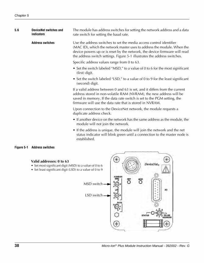
The module has address switches for setting the network address and a data rate switch for setting the baud rate.
Address switches Use the address switches to set the media access control identifier (MAC ID), which the network master uses to address the module. When the device powers up or is reset by the network, the device firmware will read the address switch settings. Figure 5-1 illustrates the address switches.
Specific address values range from 0 to 63.
• Set the switch labeled “MSD,” to a value of 0 to 6 for the most significant (first) digit.
• Set the switch labeled “LSD,” to a value of 0 to 9 for the least significant (second) digit.
If a valid address between 0 and 63 is set, and it differs from the current address stored in non-volatile RAM (NVRAM), the new address will be saved in memory. If the data rate switch is set to the PGM setting, the firmware will use the data rate that is stored in NVRAM.
Upon connection to the DeviceNet network, the module requests a duplicate address check.
• If another device on the network has the same address as the module, the module will not join the network.
• If the address is unique, the module will join the network and the net status indicator will blink green until a connection to the master node is established.
Figure 5-1 Address switches
Valid addresses: 0 to 63• Set most significant digit (MSD) to a value of 0 to 6• Set least significant digit (LSD) to a value of 0 to 9
MSD switch
LSD switch
DeviceNet Operation
Micro-Ion® Plus Module Instruction Manual - 392002 - Rev. G 39
DeviceNet OperationRS-485 Operation
Optional DisplayM
aintenance
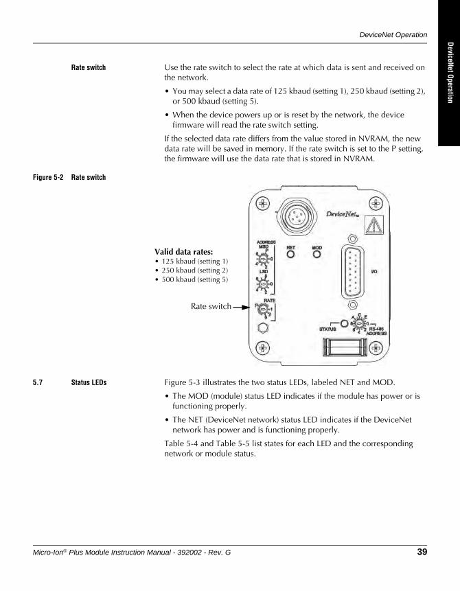
Rate switch Use the rate switch to select the rate at which data is sent and received on the network.
• You may select a data rate of 125 kbaud (setting 1), 250 kbaud (setting 2), or 500 kbaud (setting 5).
• When the device powers up or is reset by the network, the device firmware will read the rate switch setting.
If the selected data rate differs from the value stored in NVRAM, the new data rate will be saved in memory. If the rate switch is set to the P setting, the firmware will use the data rate that is stored in NVRAM.
Figure 5-2 Rate switch
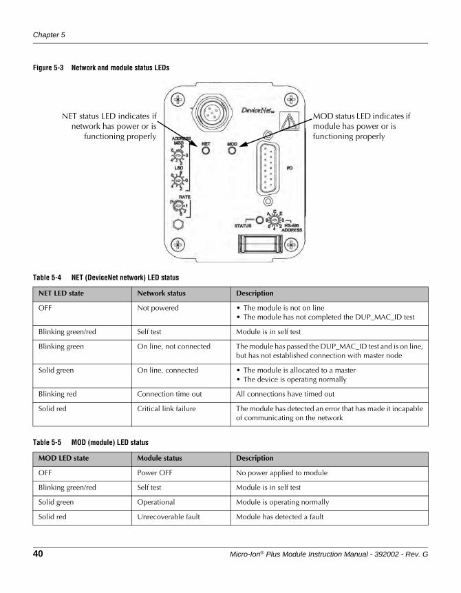
5.7 Status LEDs Figure 5-3 illustrates the two status LEDs, labeled NET and MOD.
• The MOD (module) status LED indicates if the module has power or is functioning properly.
• The NET (DeviceNet network) status LED indicates if the DeviceNet network has power and is functioning properly.
Table 5-4 and Table 5-5 list states for each LED and the corresponding network or module status.
Valid data rates:• 125 kbaud (setting 1)• 250 kbaud (setting 2)• 500 kbaud (setting 5)
Rate switch
Chapter 5
40 Micro-Ion® Plus Module Instruction Manual - 392002 - Rev. G
Figure 5-3 Network and module status LEDs
NET status LED indicates ifnetwork has power or is
functioning properly
MOD status LED indicates if module has power or is functioning properly
Table 5-4 NET (DeviceNet network) LED status
NET LED state Network status Description
OFF Not powered • The module is not on line• The module has not completed the DUP_MAC_ID test
Blinking green/red Self test Module is in self test
Blinking green On line, not connected The module has passed the DUP_MAC_ID test and is on line, but has not established connection with master node
Solid green On line, connected • The module is allocated to a master• The device is operating normally
Blinking red Connection time out All connections have timed out
Solid red Critical link failure The module has detected an error that has made it incapable of communicating on the network
Table 5-5 MOD (module) LED status
MOD LED state Module status Description
OFF Power OFF No power applied to module
Blinking green/red Self test Module is in self test
Solid green Operational Module is operating normally
Solid red Unrecoverable fault Module has detected a fault
DeviceNet Operation
Micro-Ion® Plus Module Instruction Manual - 392002 - Rev. G 41
DeviceNet OperationRS-485 Operation
Optional DisplayM
aintenance
5.8 DeviceNet communication configuration
1. Turn the external power supply OFF.
2. Set the address switches to the desired address (0 to 63). See page 38.
3. Set the data rate switch to the desired setting (125, 250, or 500 kbaud). See page 39.
4. Turn the external power supply ON.
5. Refer to Table 5-6 and Table 5-7 to allocate a connection for the module to the network master.
• Set the bit contents to 1 to enable polled I/O.
• Set the bit contents to 0 to enable explicit messages.
Table 5-6 Network master connection
Service Class Instance Attribute Data type Allocation choice bits
4Bhex 3 1 None STRUCT 0 = Explicit message1 = Polled2 = Bit strobed(a)
3 = Reserved(a)
4 = Change of state5 = Cyclic6 = Acknowledge suppression(a)
7 = Connection(a)
(a) Not supported, value = 0.
Table 5-7 Network master connections allocation choice bits
Assembly number STRUCT data: One byte format
1 Bit 7Connection
Bit 6Acknowledge suppression
Bit 5Cyclic
Bit 4Change of state
Bit 3Reserved
Bit 2Bit strobed
Bit 1Polled
Bit 0Explicit message
Chapter 5
42 Micro-Ion® Plus Module Instruction Manual - 392002 - Rev. G
6. Refer to Table 5-8 to configure the expected packet rate for messages. The expected packet rate is the rate at which the module expects to send data to and receive a packet of data from the network.
• The default expected packet rate for explicit messaging is 2500 msec (2.5 sec.).
• For polled I/O, set the expected packet rate to 0 (none).
• If data will be requested at a rate slower than every 2500 msec, you must change or disable the expected packet rate to prevent the connection from timing out.
7. If the connection allocation bit 1 (polled) is set at Step 5 on page 41, refer to Table 5-9 to configure the polled data input format and status byte and Table 5-10 to configure the polled data output format.
• You may configure the module to send data to the network in integer (INT), unsigned integer (UINT), or floating point data (REAL) formats, with or without a status byte and trip point status byte.
• The default configuration sends pressure in floating point data format with one byte of status data.
Table 5-8 Expected packet rate
Expected packet rate for explicit messaging
Service Class Instance Attribute Master data Data type Description
10hex 5 1 9 data such as09 C4hex (default)
UINT Rate at which module sends data to and receives data from network• Default is 2500 msec (2.5 sec.)• Valid time is ≤ 2500 msec (2.5 sec.)
Expected packet rate for polled I/O
Service Class Instance Attribute Master data Data type Description
10hex 5 2 9 00 00 UINT Disable expected packet rate
DeviceNet Operation
Micro-Ion® Plus Module Instruction Manual - 392002 - Rev. G 43
DeviceNet OperationRS-485 Operation
Optional DisplayM
aintenance
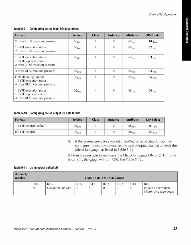
8. If the connection allocation bit 1 (polled) is set at Step 5, you may configure the module to receive one byte of input data that controls the Micro-Ion gauge, as listed in Table 5-11.
Bit 6 in the one byte format turns the Micro-Ion gauge ON or OFF. If bit 6 is set to 1, the gauge will turn ON. See Table 5-12.
Table 5-9 Configuring polled input I/O data format
Format Service Class Instance Attribute UINT data
2 bytes UINT vacuum pressure 0Ehex 4 0 65hex 01 hex
1 BYTE exception status2 bytes UINT vacuum pressure
0Ehex 4 0 65hex 02 hex
1 BYTE exception status1 BYTE trip point status2 bytes UINT vacuum pressure
0Ehex 4 0 65hex 03 hex
4 bytes REAL vacuum pressure 0Ehex 4 0 65hex 04 hex
Default configuration:1 BYTE exception status4 bytes REAL vacuum pressure
0Ehex 4 0 65hex 05 hex
1 BYTE exception status1 BYTE trip point status4 bytes REAL vacuum pressure
0Ehex 4 0 65hex 06 hex
Table 5-10 Configuring polled output I/O data format
Format Service Class Instance Attribute UINT data
1 BYTE control (default) 0Ehex 4 0 66hex 01 hex
0 BYTE control 0Ehex 4 0 66hex 00 hex
Table 5-11 Using output polled I/O
Assembly number USINT data: One byte format
1 Bit 70
Bit 6Gauge ON or OFF
Bit 50
Bit 40
Bit 30
Bit 20
Bit 10
Bit 0Initiate or terminate Micro-Ion gauge degas
Chapter 5
44 Micro-Ion® Plus Module Instruction Manual - 392002 - Rev. G
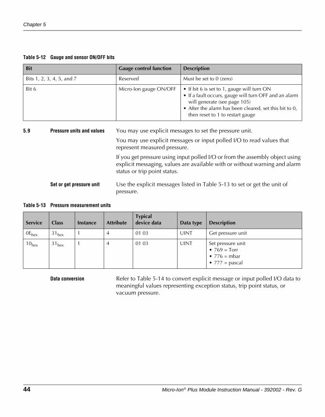
5.9 Pressure units and values You may use explicit messages to set the pressure unit.
You may use explicit messages or input polled I/O to read values that represent measured pressure.
If you get pressure using input polled I/O or from the assembly object using explicit messaging, values are available with or without warning and alarm status or trip point status.
Set or get pressure unit Use the explicit messages listed in Table 5-13 to set or get the unit of pressure.
Data conversion Refer to Table 5-14 to convert explicit message or input polled I/O data to meaningful values representing exception status, trip point status, or vacuum pressure.
Table 5-12 Gauge and sensor ON/OFF bits
Bit Gauge control function Description
Bits 1, 2, 3, 4, 5, and 7 Reserved Must be set to 0 (zero)
Bit 6 Micro-Ion gauge ON/OFF • If bit 6 is set to 1, gauge will turn ON• If a fault occurs, gauge will turn OFF and an alarm
will generate (see page 105)• After the alarm has been cleared, set this bit to 0,
then reset to 1 to restart gauge
Table 5-13 Pressure measurement units
Service Class Instance AttributeTypicaldevice data Data type Description
0Ehex 31hex 1 4 01 03 UINT Get pressure unit
10hex 31hex 1 4 01 03 UINT Set pressure unit• 769 = Torr• 776 = mbar• 777 = pascal
DeviceNet Operation
Micro-Ion® Plus Module Instruction Manual - 392002 - Rev. G 45
DeviceNet OperationRS-485 Operation
Optional DisplayM
aintenance
Get vacuum pressure You may use explicit messages or input polled I/O to read values that represent measured pressure. You must calculate measured pressure from the values represented by the explicit message or input polled I/O.
If you get pressure using input polled I/O or from the assembly object using explicit messaging, values are available with or without warning and alarm status or trip point status.
Using DeviceNet explicit messages:You may read measured pressure in the assembly object, analog sensor object (instance 0), analog sensor object Conductron sensor (instance 1), or analog sensor object Micro-Ion gauge (instance 2).
• The explicit messages for each object are listed in Table 5-15.
• You must refer to Table 5-14 to convert the BYTE, UINT, INT, or REAL data to meaningful values representing exception status, trip point status, or vacuum pressure.
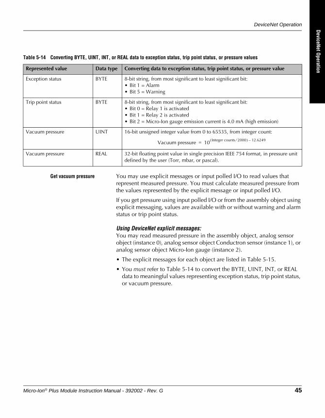
Table 5-14 Converting BYTE, UINT, INT, or REAL data to exception status, trip point status, or pressure values
Represented value Data type Converting data to exception status, trip point status, or pressure value
Exception status BYTE 8-bit string, from most significant to least significant bit:• Bit 1 = Alarm• Bit 5 = Warning
Trip point status BYTE 8-bit string, from most significant to least significant bit:• Bit 0 = Relay 1 is activated• Bit 1 = Relay 2 is activated• Bit 2 = Micro-Ion gauge emission current is 4.0 mA (high emission)
Vacuum pressure UINT 16-bit unsigned integer value from 0 to 65535, from integer count:
Vacuum pressure REAL 32-bit floating point value in single precision IEEE 754 format, in pressure unit defined by the user (Torr, mbar, or pascal).
Vacuum pressure 10 Integer counts 2000⁄( ) 12.6249–=
Chapter 5
46 Micro-Ion® Plus Module Instruction Manual - 392002 - Rev. G
Using input polled I/O:When a master polls the module for measured pressure, the format of the returned pressure value depends on the data type. See Table 5-16.
• To configure the data format for input polled I/O, see Step 7 on page 42.
• You must refer to Table 5-14 to convert the BYTE, UINT, INT, or REAL data to meaningful values representing exception status, trip point status, or vacuum pressure.
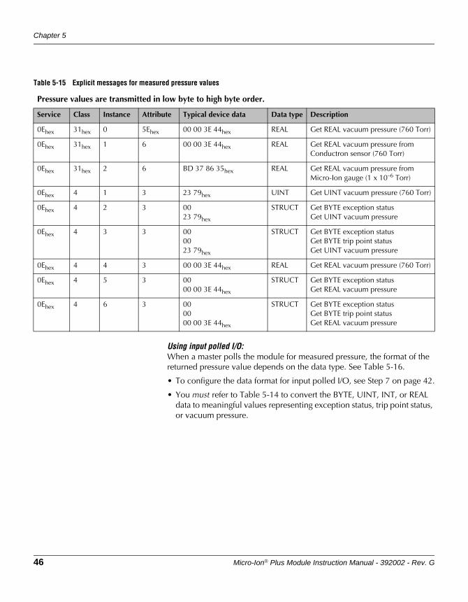
Table 5-15 Explicit messages for measured pressure values
Pressure values are transmitted in low byte to high byte order.
Service Class Instance Attribute Typical device data Data type Description
0Ehex 31hex 0 5Ehex 00 00 3E 44hex REAL Get REAL vacuum pressure (760 Torr)
0Ehex 31hex 1 6 00 00 3E 44hex REAL Get REAL vacuum pressure from Conductron sensor (760 Torr)
0Ehex 31hex 2 6 BD 37 86 35hex REAL Get REAL vacuum pressure from Micro-Ion gauge (1 x 10⁻⁶ Torr)
0Ehex 4 1 3 23 79hex UINT Get UINT vacuum pressure (760 Torr)
0Ehex 4 2 3 0023 79hex
STRUCT Get BYTE exception statusGet UINT vacuum pressure
0Ehex 4 3 3 000023 79hex
STRUCT Get BYTE exception statusGet BYTE trip point statusGet UINT vacuum pressure
0Ehex 4 4 3 00 00 3E 44hex REAL Get REAL vacuum pressure (760 Torr)
0Ehex 4 5 3 0000 00 3E 44hex
STRUCT Get BYTE exception statusGet REAL vacuum pressure
0Ehex 4 6 3 000000 00 3E 44hex
STRUCT Get BYTE exception statusGet BYTE trip point statusGet REAL vacuum pressure
DeviceNet Operation
Micro-Ion® Plus Module Instruction Manual - 392002 - Rev. G 47
DeviceNet OperationRS-485 Operation
Optional DisplayM
aintenance
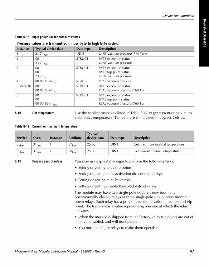
5.10 Get temperature Use the explicit messages listed in Table 5-17 to get current or maximum electronics temperature. Temperature is indicated in degrees Celsius.
5.11 Process control relays You may use explicit messages to perform the following tasks:
• Setting or getting relay trip points
• Setting or getting relay activation direction (polarity)
• Setting or getting relay hysteresis
• Setting or getting disabled/enabled state of relays
The module may have two single-pole double-throw (normally open/normally closed) relays or three single-pole single-throw (normally open) relays. Each relay has a programmable activation direction and trip point. The trip point is a value representing pressure at which the relay activates.
• When the module is shipped from the factory, relay trip points are out of range, disabled, and will not operate.
• You must configure relays to make them operable.
Table 5-16 Input polled I/O for pressure values
Pressure values are transmitted in low byte to high byte order.Instance Typical device data Data type Description
1 23 79hex UINT UINT vacuum pressure (760 Torr)
2 0023 79hex
STRUCT BYTE exception statusUINT vacuum pressure
3 000023 79hex
STRUCT BYTE exception statusBYTE trip point statusUINT vacuum pressure
4 00 00 3E 44hex REAL REAL vacuum pressure
5 (default) 0000 00 3E 44hex
STRUCT BYTE exception statusREAL vacuum pressure (760 Torr)
6 000000 00 3E 44hex
STRUCT BYTE exception statusBYTE trip point statusREAL vacuum pressure (760 Torr)
Table 5-17 Current or maximum temperature
Service Class Instance AttributeTypical device data Data type Description
0Ehex 31hex 1 67hex 25 00 UINT Get maximum internal temperature
0Ehex 31hex 1 68hex 25 00 UINT Get current internal temperature
Chapter 5
48 Micro-Ion® Plus Module Instruction Manual - 392002 - Rev. G
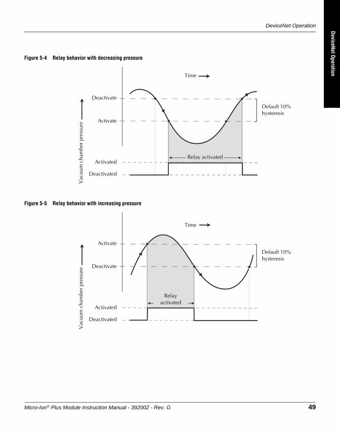
In default mode, trip point relays activate with decreasing pressure and deactivate at a higher pressure than the activation pressure, as illustrated in Figure 5-4.
You can reverse relay polarity, so trip point relays activate with increasing pressure and deactivate at a lower pressure than the activation pressure, as illustrated in Figure 5-5.
• You may change the deactivation pressure by entering REAL data that represents hysteresis as a percentage of the activation pressure.
• Valid hysteresis values are any activation pressure percentage, from 5% to 10,000%, that is divisible by 5.
Use the explicit messages listed in Table 5-19 to configure trip point relays.
DeviceNet Operation
Micro-Ion® Plus Module Instruction Manual - 392002 - Rev. G 49
DeviceNet OperationRS-485 Operation
Optional DisplayM
aintenance
Figure 5-4 Relay behavior with decreasing pressure
Figure 5-5 Relay behavior with increasing pressure
Deactivate
Activate
Deactivated
Activated
TimeV
acuu
m c
ham
ber
pres
sure
Relay activated
Default 10% hysteresis
Activate
Deactivate
Deactivated
Activated
Relay activated
Time
Vac
uum
cha
mbe
r pr
essu
re
Default 10% hysteresis
Chapter 5
50 Micro-Ion® Plus Module Instruction Manual - 392002 - Rev. G
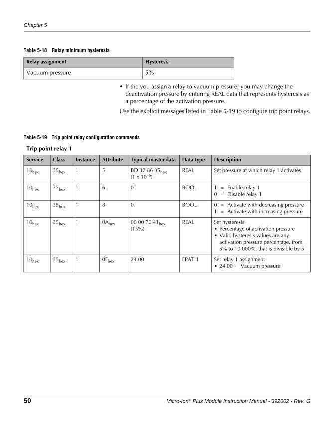
• If the you assign a relay to vacuum pressure, you may change the deactivation pressure by entering REAL data that represents hysteresis as a percentage of the activation pressure.
Use the explicit messages listed in Table 5-19 to configure trip point relays.
Table 5-18 Relay minimum hysteresis
Relay assignment Hysteresis
Vacuum pressure 5%
Table 5-19 Trip point relay configuration commands
Trip point relay 1
Service Class Instance Attribute Typical master data Data type Description
10hex 35hex 1 5 BD 37 86 35hex(1 x 10–6)
REAL Set pressure at which relay 1 activates
10hex 35hex 1 6 0 BOOL 1 = Enable relay 10 = Disable relay 1
10hex 35hex 1 8 0 BOOL 0 = Activate with decreasing pressure1 = Activate with increasing pressure
10hex 35hex 1 0Ahex 00 00 70 41hex (15%)
REAL Set hysteresis• Percentage of activation pressure• Valid hysteresis values are any
activation pressure percentage, from 5% to 10,000%, that is divisible by 5
10hex 35hex 1 0Ehex 24 00 EPATH Set relay 1 assignment• 24 00= Vacuum pressure
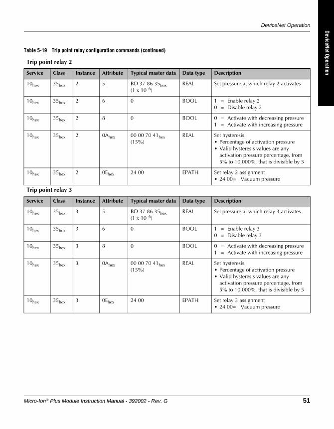
DeviceNet Operation
Micro-Ion® Plus Module Instruction Manual - 392002 - Rev. G 51
DeviceNet OperationRS-485 Operation
Optional DisplayM
aintenance
Table 5-19 Trip point relay configuration commands (continued)
Trip point relay 2
Service Class Instance Attribute Typical master data Data type Description
10hex 35hex 2 5 BD 37 86 35hex(1 x 10–6)
REAL Set pressure at which relay 2 activates
10hex 35hex 2 6 0 BOOL 1 = Enable relay 20 = Disable relay 2
10hex 35hex 2 8 0 BOOL 0 = Activate with decreasing pressure1 = Activate with increasing pressure
10hex 35hex 2 0Ahex 00 00 70 41hex (15%)
REAL Set hysteresis• Percentage of activation pressure• Valid hysteresis values are any
activation pressure percentage, from 5% to 10,000%, that is divisible by 5
10hex 35hex 2 0Ehex 24 00 EPATH Set relay 2 assignment• 24 00= Vacuum pressure
Trip point relay 3
Service Class Instance Attribute Typical master data Data type Description
10hex 35hex 3 5 BD 37 86 35hex(1 x 10–6)
REAL Set pressure at which relay 3 activates
10hex 35hex 3 6 0 BOOL 1 = Enable relay 30 = Disable relay 3
10hex 35hex 3 8 0 BOOL 0 = Activate with decreasing pressure1 = Activate with increasing pressure
10hex 35hex 3 0Ahex 00 00 70 41hex (15%)
REAL Set hysteresis• Percentage of activation pressure• Valid hysteresis values are any
activation pressure percentage, from 5% to 10,000%, that is divisible by 5
10hex 35hex 3 0Ehex 24 00 EPATH Set relay 3 assignment• 24 00= Vacuum pressure
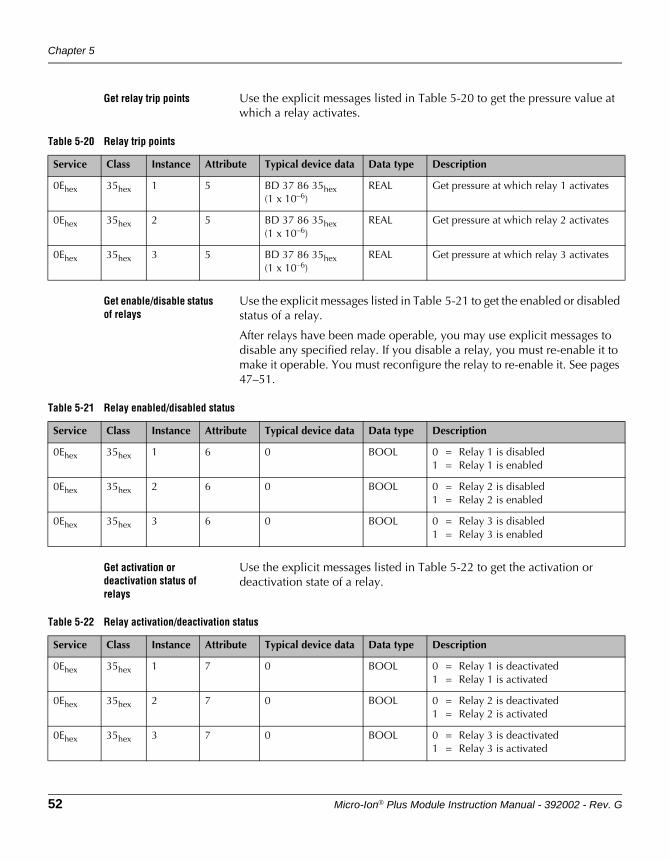
Chapter 5
52 Micro-Ion® Plus Module Instruction Manual - 392002 - Rev. G
Get relay trip points Use the explicit messages listed in Table 5-20 to get the pressure value at which a relay activates.
Get enable/disable status of relays
Use the explicit messages listed in Table 5-21 to get the enabled or disabled status of a relay.
After relays have been made operable, you may use explicit messages to disable any specified relay. If you disable a relay, you must re-enable it to make it operable. You must reconfigure the relay to re-enable it. See pages 47–51.
Get activation or deactivation status of relays
Use the explicit messages listed in Table 5-22 to get the activation or deactivation state of a relay.
Table 5-20 Relay trip points
Service Class Instance Attribute Typical device data Data type Description
0Ehex 35hex 1 5 BD 37 86 35hex(1 x 10–6)
REAL Get pressure at which relay 1 activates
0Ehex 35hex 2 5 BD 37 86 35hex(1 x 10–6)
REAL Get pressure at which relay 2 activates
0Ehex 35hex 3 5 BD 37 86 35hex(1 x 10–6)
REAL Get pressure at which relay 3 activates
Table 5-21 Relay enabled/disabled status
Service Class Instance Attribute Typical device data Data type Description
0Ehex 35hex 1 6 0 BOOL 0 = Relay 1 is disabled1 = Relay 1 is enabled
0Ehex 35hex 2 6 0 BOOL 0 = Relay 2 is disabled1 = Relay 2 is enabled
0Ehex 35hex 3 6 0 BOOL 0 = Relay 3 is disabled1 = Relay 3 is enabled
Table 5-22 Relay activation/deactivation status
Service Class Instance Attribute Typical device data Data type Description
0Ehex 35hex 1 7 0 BOOL 0 = Relay 1 is deactivated1 = Relay 1 is activated
0Ehex 35hex 2 7 0 BOOL 0 = Relay 2 is deactivated1 = Relay 2 is activated
0Ehex 35hex 3 7 0 BOOL 0 = Relay 3 is deactivated1 = Relay 3 is activated
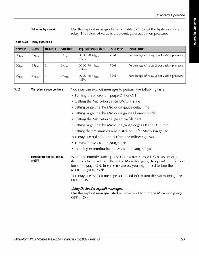
DeviceNet Operation
Micro-Ion® Plus Module Instruction Manual - 392002 - Rev. G 53
DeviceNet OperationRS-485 Operation
Optional DisplayM
aintenance
Get relay hysteresis Use the explicit messages listed in Table 5-23 to get the hysteresis for a relay. The returned value is a percentage of activation pressure.
5.12 Micro-Ion gauge controls You may use explicit messages to perform the following tasks:
• Turning the Micro-Ion gauge ON or OFF
• Getting the Micro-Ion gauge ON/OFF state
• Setting or getting the Micro-Ion gauge delay time
• Setting or getting the Micro-Ion gauge filament mode
• Getting the Micro-Ion gauge active filament
• Setting or getting the Micro-Ion gauge degas ON or OFF state
• Setting the emission current switch point for Micro-Ion gauge
You may use polled I/O to perform the following tasks:
• Turning the Micro-Ion gauge OFF
• Initiating or terminating the Micro-Ion gauge degas
Turn Micro-Ion gauge ON or OFF
When the module starts up, the Conductron sensor is ON. As pressure decreases to a level that allows the Micro-Ion gauge to operate, the sensor turns the gauge ON. In some instances, you might need to turn the Micro-Ion gauge OFF.
You may use explicit messages or polled I/O to turn the Micro-Ion gauge OFF or ON.
Using DeviceNet explicit messages:Use the explicit message listed in Table 5-24 to turn the Micro-Ion gauge OFF or ON.
Table 5-23 Relay hysteresis
Service Class Instance Attribute Typical device data Data type Description
0Ehex 35hex 1 0Ahex 00 00 70 41hex (15%)
REAL Percentage of relay 1 activation pressure
0Ehex 35hex 2 0Ahex 00 00 70 41hex (15%)
REAL Percentage of relay 2 activation pressure
0Ehex 35hex 3 0Ahex 00 00 70 41hex (15%)
REAL Percentage of relay 3 activation pressure
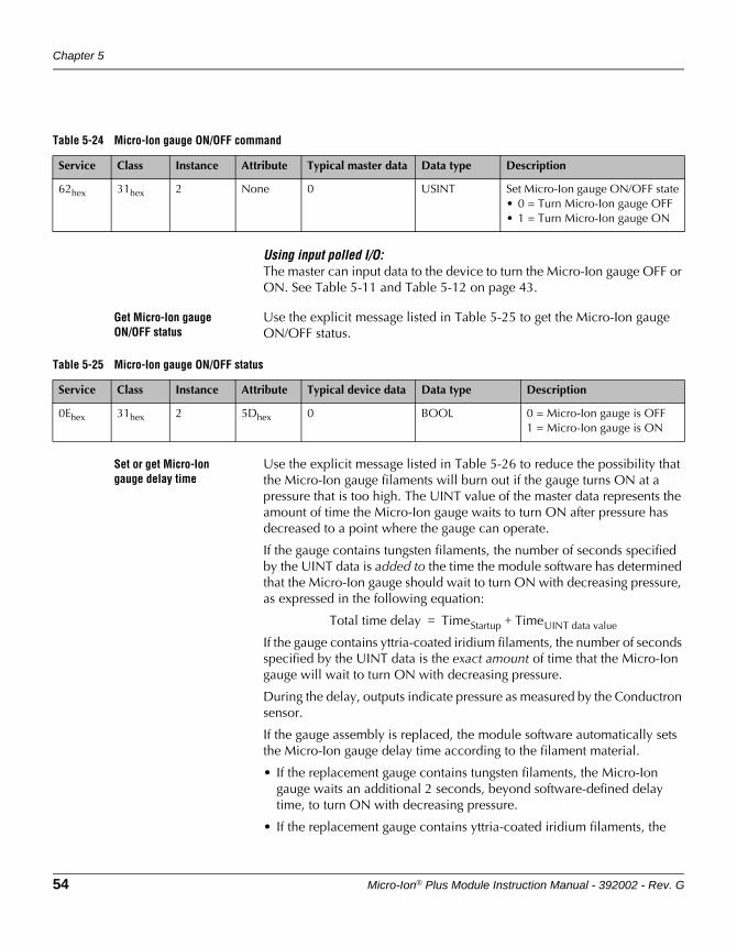
Chapter 5
54 Micro-Ion® Plus Module Instruction Manual - 392002 - Rev. G
Using input polled I/O:The master can input data to the device to turn the Micro-Ion gauge OFF or ON. See Table 5-11 and Table 5-12 on page 43.
Get Micro-Ion gauge ON/OFF status
Use the explicit message listed in Table 5-25 to get the Micro-Ion gauge ON/OFF status.
Set or get Micro-Ion gauge delay time
Use the explicit message listed in Table 5-26 to reduce the possibility that the Micro-Ion gauge filaments will burn out if the gauge turns ON at a pressure that is too high. The UINT value of the master data represents the amount of time the Micro-Ion gauge waits to turn ON after pressure has decreased to a point where the gauge can operate.
If the gauge contains tungsten filaments, the number of seconds specified by the UINT data is added to the time the module software has determined that the Micro-Ion gauge should wait to turn ON with decreasing pressure, as expressed in the following equation:
If the gauge contains yttria-coated iridium filaments, the number of seconds specified by the UINT data is the exact amount of time that the Micro-Ion gauge will wait to turn ON with decreasing pressure.
During the delay, outputs indicate pressure as measured by the Conductron sensor.
If the gauge assembly is replaced, the module software automatically sets the Micro-Ion gauge delay time according to the filament material.
• If the replacement gauge contains tungsten filaments, the Micro-Ion gauge waits an additional 2 seconds, beyond software-defined delay time, to turn ON with decreasing pressure.
• If the replacement gauge contains yttria-coated iridium filaments, the
Table 5-24 Micro-Ion gauge ON/OFF command
Service Class Instance Attribute Typical master data Data type Description
62hex 31hex 2 None 0 USINT Set Micro-Ion gauge ON/OFF state• 0 = Turn Micro-Ion gauge OFF• 1 = Turn Micro-Ion gauge ON
Table 5-25 Micro-Ion gauge ON/OFF status
Service Class Instance Attribute Typical device data Data type Description
0Ehex 31hex 2 5Dhex 0 BOOL 0 = Micro-Ion gauge is OFF1 = Micro-Ion gauge is ON
Total time delay TimeStartup TimeUINT data value+=
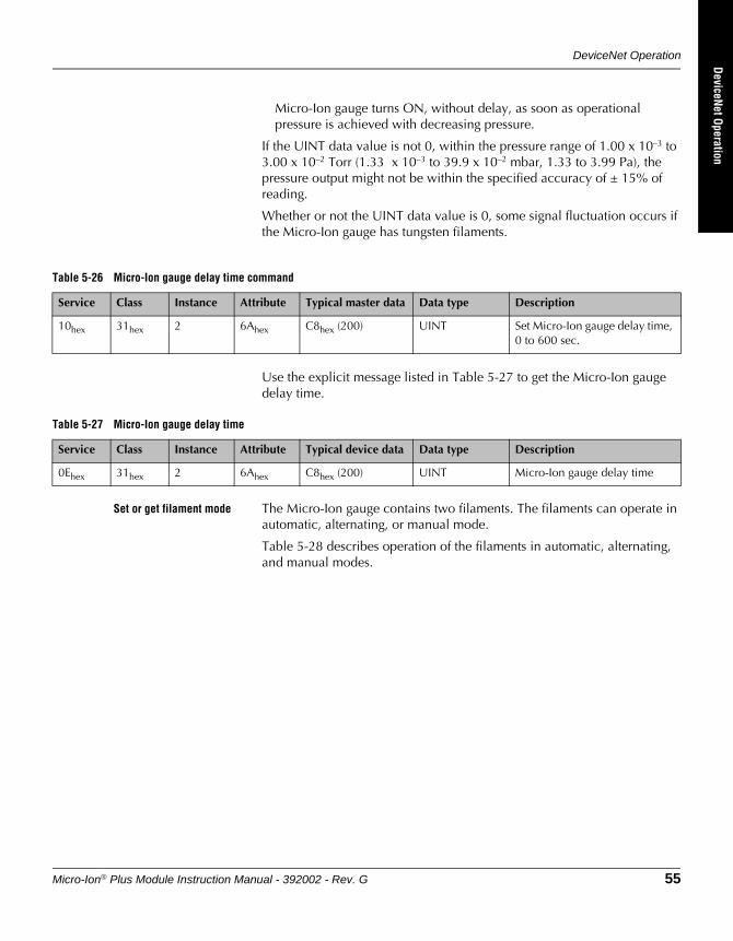
DeviceNet Operation
Micro-Ion® Plus Module Instruction Manual - 392002 - Rev. G 55
DeviceNet OperationRS-485 Operation
Optional DisplayM
aintenance
Micro-Ion gauge turns ON, without delay, as soon as operational pressure is achieved with decreasing pressure.
If the UINT data value is not 0, within the pressure range of 1.00 x 10⁻³ to 3.00 x 10⁻² Torr (1.33 x 10⁻³ to 39.9 x 10⁻² mbar, 1.33 to 3.99 Pa), the pressure output might not be within the specified accuracy of ± 15% of reading.
Whether or not the UINT data value is 0, some signal fluctuation occurs if the Micro-Ion gauge has tungsten filaments.
Use the explicit message listed in Table 5-27 to get the Micro-Ion gauge delay time.
Set or get filament mode The Micro-Ion gauge contains two filaments. The filaments can operate in automatic, alternating, or manual mode.
Table 5-28 describes operation of the filaments in automatic, alternating, and manual modes.
Table 5-26 Micro-Ion gauge delay time command
Service Class Instance Attribute Typical master data Data type Description
10hex 31hex 2 6Ahex C8hex (200) UINT Set Micro-Ion gauge delay time, 0 to 600 sec.
Table 5-27 Micro-Ion gauge delay time
Service Class Instance Attribute Typical device data Data type Description
0Ehex 31hex 2 6Ahex C8hex (200) UINT Micro-Ion gauge delay time
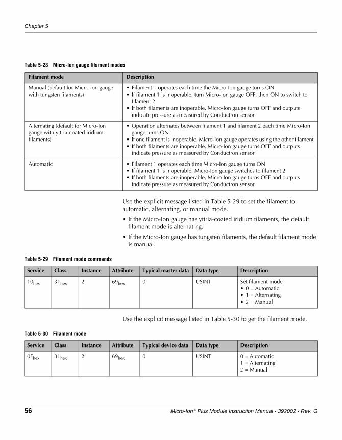
Chapter 5
56 Micro-Ion® Plus Module Instruction Manual - 392002 - Rev. G
Use the explicit message listed in Table 5-29 to set the filament to automatic, alternating, or manual mode.
• If the Micro-Ion gauge has yttria-coated iridium filaments, the default filament mode is alternating.
• If the Micro-Ion gauge has tungsten filaments, the default filament mode is manual.
Use the explicit message listed in Table 5-30 to get the filament mode.
Table 5-28 Micro-Ion gauge filament modes
Filament mode Description
Manual (default for Micro-Ion gauge with tungsten filaments)
• Filament 1 operates each time the Micro-Ion gauge turns ON• If filament 1 is inoperable, turn Micro-Ion gauge OFF, then ON to switch to
filament 2• If both filaments are inoperable, Micro-Ion gauge turns OFF and outputs
indicate pressure as measured by Conductron sensor
Alternating (default for Micro-Ion gauge with yttria-coated iridium filaments)
• Operation alternates between filament 1 and filament 2 each time Micro-Ion gauge turns ON
• If one filament is inoperable, Micro-Ion gauge operates using the other filament• If both filaments are inoperable, Micro-Ion gauge turns OFF and outputs
indicate pressure as measured by Conductron sensor
Automatic • Filament 1 operates each time Micro-Ion gauge turns ON• If filament 1 is inoperable, Micro-Ion gauge switches to filament 2• If both filaments are inoperable, Micro-Ion gauge turns OFF and outputs
indicate pressure as measured by Conductron sensor
Table 5-29 Filament mode commands
Service Class Instance Attribute Typical master data Data type Description
10hex 31hex 2 69hex 0 USINT Set filament mode• 0 = Automatic• 1 = Alternating• 2 = Manual
Table 5-30 Filament mode
Service Class Instance Attribute Typical device data Data type Description
0Ehex 31hex 2 69hex 0 USINT 0 = Automatic1 = Alternating2 = Manual
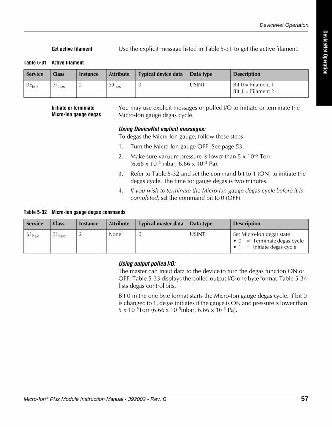
DeviceNet Operation
Micro-Ion® Plus Module Instruction Manual - 392002 - Rev. G 57
DeviceNet OperationRS-485 Operation
Optional DisplayM
aintenance
Get active filament Use the explicit message listed in Table 5-31 to get the active filament.
Initiate or terminate Micro-Ion gauge degas
You may use explicit messages or polled I/O to initiate or terminate the Micro-Ion gauge degas cycle.
Using DeviceNet explicit messages:To degas the Micro-Ion gauge, follow these steps:
1. Turn the Micro-Ion gauge OFF. See page 53.
2. Make sure vacuum pressure is lower than 5 x 10⁻⁵ Torr (6.66 x 10⁻⁵ mbar, 6.66 x 10⁻³ Pa).
3. Refer to Table 5-32 and set the command bit to 1 (ON) to initiate the degas cycle. The time for gauge degas is two minutes.
4. If you wish to terminate the Micro-Ion gauge degas cycle before it is completed, set the command bit to 0 (OFF).
Using output polled I/O:The master can input data to the device to turn the degas function ON or OFF. Table 5-33 displays the polled output I/O one byte format. Table 5-34 lists degas control bits.
Bit 0 in the one byte format starts the Micro-Ion gauge degas cycle. If bit 0 is changed to 1, degas initiates if the gauge is ON and pressure is lower than 5 x 10⁻⁵Torr (6.66 x 10⁻⁵mbar, 6.66 x 10⁻³ Pa).
Table 5-31 Active filament
Service Class Instance Attribute Typical device data Data type Description
0Ehex 31hex 2 59hex 0 USINT Bit 0 = Filament 1Bit 1 = Filament 2
Table 5-32 Micro-Ion gauge degas commands
Service Class Instance Attribute Typical master data Data type Description
61hex 31hex 2 None 0 USINT Set Micro-Ion degas state• 0 = Terminate degas cycle• 1 = Initiate degas cycle
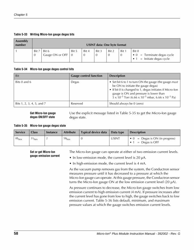
Chapter 5
58 Micro-Ion® Plus Module Instruction Manual - 392002 - Rev. G
Get Micro-Ion gauge degas ON/OFF state
Use the explicit message listed in Table 5-35 to get the Micro-Ion gauge degas state.
Set or get Micro-Ion gauge emission current
The Micro-Ion gauge can operate at either of two emission current levels.
• In low-emission mode, the current level is 20 µA.
• In high-emission mode, the current level is 4 mA.
As the vacuum pump removes gas from the system, the Conductron sensor measures pressure until it has decreased to a pressure at which the Micro-Ion gauge can operate. At this gauge pressure, the Conductron sensor turns the Micro-Ion gauge ON at the low emission current level (20 µA).
As pressure continues to decrease, the Micro-Ion gauge switches from low emission current to high emission current (4 mA). If pressure increases after the current level has gone from low to high, the gauge switches back to low emission current. Table 5-36 lists default, minimum, and maximum pressure values at which the gauge switches emission current levels.
Table 5-33 Writing Micro-Ion gauge degas bits
Assembly number USINT data: One byte format
1 Bit 70
Bit 6Gauge ON or OFF
Bit 50
Bit 40
Bit 30
Bit 20
Bit 10
Bit 0• 0 = Terminate degas cycle• 1 = Initiate degas cycle
Table 5-34 Micro-Ion gauge degas control bits
Bit Gauge control function Description
Bits 0 and 6 Degas • Set bit 6 to 1 to turn ON the gauge (the gauge must be ON to initiate the gauge degas)
• If bit 0 is changed to 1, degas initiates if Micro-Ion gauge is ON and pressure is lower than 5 x 10⁻⁵ Torr (6.66 x 10⁻⁵ mbar, 6.66 x 10⁻³ Pa)
Bits 1, 2, 3, 4, 5, and 7 Reserved Should always be 0 (zero)
Table 5-35 Micro-Ion gauge degas state
Service Class Instance Attribute Typical device data Data type Description
0Ehex 31hex 2 58hex 0 USINT • 0 = Degas is ON (in progress)• 1 = Degas is OFF
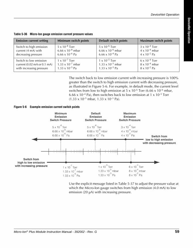
DeviceNet Operation
Micro-Ion® Plus Module Instruction Manual - 392002 - Rev. G 59
DeviceNet OperationRS-485 Operation
Optional DisplayM
aintenance
The switch back to low emission current with increasing pressure is 100% greater than the switch to high emission current with decreasing pressure, as illustrated in Figure 5-6. For example, in default mode, the current level switches from low to high emission at 5 x 10⁻⁶ Torr (6.66 x 10⁻⁶ mbar, 6.66 x 10⁻⁴ Pa), then switches back to low emission at 1 x 10⁻⁵ Torr (1.33 x 10⁻⁵ mbar, 1.33 x 10⁻³ Pa).
Figure 5-6 Example emission current switch points
Use the explicit message listed in Table 5-37 to adjust the pressure value at which the Micro-Ion gauge switches from high emission (4.0 mA) to low emission (20 µA) with increasing pressure.
Table 5-36 Micro-Ion gauge emission current pressure values
Emission current setting Minimum switch points Default switch points Maximum switch points
Switch to high emission current (4 mA) with decreasing pressure
5 x 10⁻⁸ Torr6.66 x 10–8 mbar6.66 x 10–6 Pa
5 x 10⁻⁶ Torr6.66 x 10–6 mbar6.66 x 10–4 Pa
3 x 10⁻⁴ Torr4 x 10–4 mbar4 x 10–2 Pa
Switch to low emission current (0.02 mA or 0.1 mA) with increasing pressure
1 x 10⁻⁷ Torr1.33 x 10–7 mbar1.33 x 10–5 Pa
1 x 10⁻⁵ Torr1.33 x 10–5 mbar1.33 x 10–3 Pa
6 x 10⁻⁴ Torr8 x 10–4 mbar8 x 10–2 Pa
Chapter 5
60 Micro-Ion® Plus Module Instruction Manual - 392002 - Rev. G
Use the explicit command listed in Table 5-38 to get the emission current switch point.
5.13 Calibrate module at atmospheric pressure
Atmospheric pressure calibration is performed using N2 at the factory before the module is shipped.
If the atmospheric pressure calibration value is too low, the Micro-Ion gauge will not turn ON.
Use N2 or air to calibrate the module at atmospheric pressure. Minimum valid calibration pressure is 500 Torr (666 mbar, 6.66 x 10⁴ Pa).
1. Shut the pump OFF and, using N2 or air, allow the vacuum pressure to increase until it equals atmospheric pressure.
2. Use the explicit message listed in Table 5-39 to perform the atmospheric pressure calibration.
5.14 Calibrate module at vacuum pressure
Ordinarily, the Conductron sensor turns the Micro-Ion gauge ON when pressure decreases to 2 x 10⁻² Torr (2.66 x 10⁻² mbar, 2.66 Pa). However, if the Conductron sensor calibration has shifted so that the Micro-Ion gauge cannot turn ON, you can recalibrate the module for vacuum pressure.
Use N2 or air to calibrate the module at vacuum pressure. Maximum valid calibration pressure is 3.00 x 10⁻² Torr (3.99 x 10⁻² mbar, 3.99 Pa).
1. Turn the pump ON and, using N2 or air, allow the vacuum chamber to decrease to the optimal calibration pressure of 1 x 10⁻⁴ Torr (1.33 x 10⁻⁴ mbar, 1.33 x 10⁻² Pa) or a lower pressure.
2. Use the explicit message listed in Table 5-39 to perform the vacuum pressure calibration.
Table 5-37 Emission current switch point command
Service Class Instance Attribute Typical master data Data type Description
10hex 35hex 4 5 AC C5 A7 36hex(5 x 10–6 Torr)
SET emission current switch point, emission ranging(5 x 10⁻⁶ Torr)
Table 5-38 Emission current switch point
Service Class Instance Attribute Typical device data Data type Description
0Ehex 35hex 4 5 AC C5 A7 36hex(5 x 10–6 Torr)
REAL GET emission current switch point, emission ranging(5 x 10⁻⁶ Torr)
DeviceNet Operation
Micro-Ion® Plus Module Instruction Manual - 392002 - Rev. G 61
DeviceNet OperationRS-485 Operation
Optional DisplayM
aintenance
5.15 Reset module to power-up state
Use the explicit message listed in Table 5-40 to reset the module to power-up status.
Resetting the module to power-up status has the same effect as cycling power to the module. Communication is re-enabled two seconds after you’ve sent the explicit message.
5.16 Get firmware version Use the explicit messages listed in Table 5-41 to get the firmware version for the module.
5.17 Get software and hardware revision levels
Use the explicit messages listed in Table 5-42 to get the software and hardware revision levels for the module.
Table 5-39 Vacuum pressure or atmospheric pressure calibration command
Service Class Instance Attribute Master data Data type Description
4Bhex 31hex 1 None None None Calibrate module at vacuum pressure
4Chex 31hex 1 None None None Calibrate module at atmospheric pressure
Table 5-40 Reset to power-up state command
Service Class Instance Attribute Master data Data type Description
05hex 1 1 None None None Reset module to power-up state
Table 5-41 Firmware version command
Service Class Instance Attribute Device data Data type Description
0Ehex 1 1 4 01 01 None Get firmware version
Table 5-42 Software and hardware revision commands
Service Class Instance Attribute Device data Data type Description
0Ehex 30hex 1 7 “1.01” SSTRING Get software revision level
0Ehex 30hex 1 8 “1.01” SSTRING Get hardware revision level
Chapter 5
62 Micro-Ion® Plus Module Instruction Manual - 392002 - Rev. G
5.18 Factory defaults Micro-Ion Plus modules are shipped with the default settings listed in Table 5-43. If options in your application require settings different from the factory defaults listed in Table 5-43, you may change the settings.
• Some settings can be changed only through the DeviceNet interface.
• You may reconfigure options before or after completing the basic setup procedures described in this chapter.
Table 5-43 Factory default settings
Parameter Default setting
Digital communication Baud rate: 500 kbaud
Vacuum calibration pressure 1 x 10⁻⁴ Torr (1.33 x 10⁻⁴ mbar, 1.33 x 10⁻² Pa)
Atmospheric calibration pressure 760 Torr (1013 mbar, 1.01 x 10⁵ Pa)
Relay 1 trip point Disabled
Relay 2 trip point Disabled
Relay 3 trip point Disabled
Trip point polarity • 10% hysteresis• Polarity default set for decreasing pressure
Micro-Ion gauge filament mode • Alternating for yttria-coated iridium filaments• Manual for tungsten filaments
Micro-Ion gauge emission current switch point • With decreasing pressure:5 x 10⁻⁶ Torr6.66 x 10–6 mbar6.66 x 10–4 Pa
• With increasing pressure:1 x 10⁻⁵ Torr1.33 x 10–5 mbar1.33 x 10–3 Pa
Unit of measure As specified by the catalog number:• T = Torr• M = mbar• P = pascal
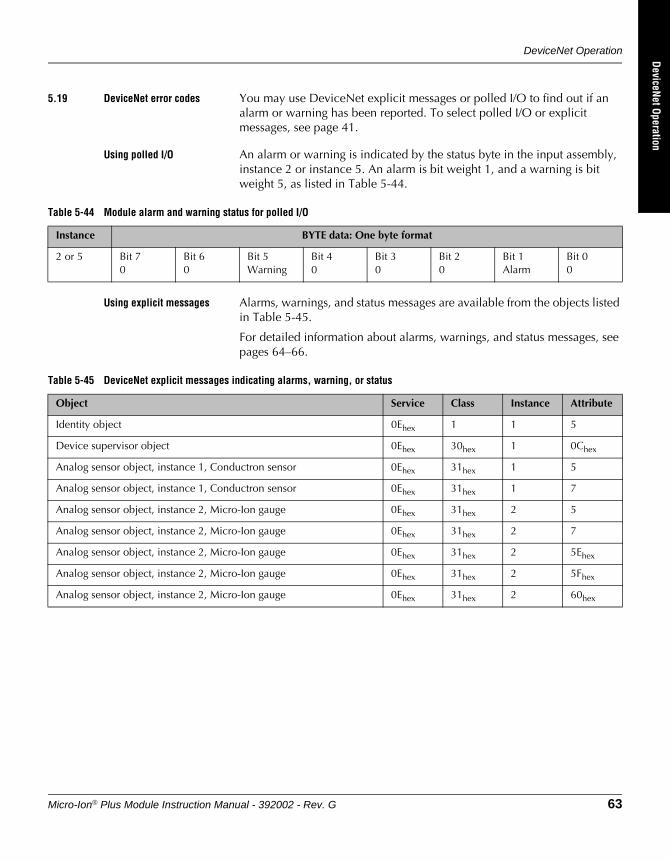
DeviceNet Operation
Micro-Ion® Plus Module Instruction Manual - 392002 - Rev. G 63
DeviceNet OperationRS-485 Operation
Optional DisplayM
aintenance
5.19 DeviceNet error codes You may use DeviceNet explicit messages or polled I/O to find out if an alarm or warning has been reported. To select polled I/O or explicit messages, see page 41.
Using polled I/O An alarm or warning is indicated by the status byte in the input assembly, instance 2 or instance 5. An alarm is bit weight 1, and a warning is bit weight 5, as listed in Table 5-44.
Using explicit messages Alarms, warnings, and status messages are available from the objects listed in Table 5-45.
For detailed information about alarms, warnings, and status messages, see pages 64–66.
Table 5-44 Module alarm and warning status for polled I/O
Instance BYTE data: One byte format
2 or 5 Bit 70
Bit 60
Bit 5Warning
Bit 40
Bit 30
Bit 20
Bit 1Alarm
Bit 00
Table 5-45 DeviceNet explicit messages indicating alarms, warning, or status
Object Service Class Instance Attribute
Identity object 0Ehex 1 1 5
Device supervisor object 0Ehex 30hex 1 0Chex
Analog sensor object, instance 1, Conductron sensor 0Ehex 31hex 1 5
Analog sensor object, instance 1, Conductron sensor 0Ehex 31hex 1 7
Analog sensor object, instance 2, Micro-Ion gauge 0Ehex 31hex 2 5
Analog sensor object, instance 2, Micro-Ion gauge 0Ehex 31hex 2 7
Analog sensor object, instance 2, Micro-Ion gauge 0Ehex 31hex 2 5Ehex
Analog sensor object, instance 2, Micro-Ion gauge 0Ehex 31hex 2 5Fhex
Analog sensor object, instance 2, Micro-Ion gauge 0Ehex 31hex 2 60hex
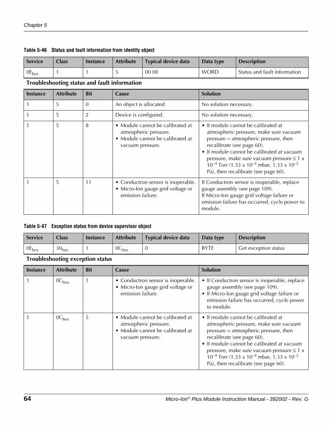
Chapter 5
64 Micro-Ion® Plus Module Instruction Manual - 392002 - Rev. G
Table 5-46 Status and fault information from identity object
Service Class Instance Attribute Typical device data Data type Description
0Ehex 1 1 5 00 00 WORD Status and fault information
Troubleshooting status and fault information
Instance Attribute Bit Cause Solution
1 5 0 An object is allocated. No solution necessary.
1 5 2 Device is configured. No solution necessary.
1 5 8 • Module cannot be calibrated at atmospheric pressure.
• Module cannot be calibrated at vacuum pressure.
• If module cannot be calibrated at atmospheric pressure, make sure vacuum pressure = atmospheric pressure, then recalibrate (see page 60).
• If module cannot be calibrated at vacuum pressure, make sure vacuum pressure ≤ 1 x 10⁻⁴ Torr (1.33 x 10⁻⁴ mbar, 1.33 x 10⁻² Pa), then recalibrate (see page 60).
1 5 11 • Conductron sensor is inoperable.• Micro-Ion gauge grid voltage or
emission failure.
If Conductron sensor is inoperable, replace gauge assembly (see page 109).If Micro-Ion gauge grid voltage failure or emission failure has occurred, cycle power to module.
Table 5-47 Exception status from device supervisor object
Service Class Instance Attribute Typical device data Data type Description
0Ehex 30hex 1 0Chex 0 BYTE Get exception status
Troubleshooting exception status
Instance Attribute Bit Cause Solution
1 0Chex 1 • Conductron sensor is inoperable.• Micro-Ion gauge grid voltage or
emission failure.
• If Conductron sensor is inoperable, replace gauge assembly (see page 109).
• If Micro-Ion gauge grid voltage failure or emission failure has occurred, cycle power to module.
1 0Chex 5 • Module cannot be calibrated at atmospheric pressure.
• Module cannot be calibrated at vacuum pressure.
• If module cannot be calibrated at atmospheric pressure, make sure vacuum pressure = atmospheric pressure, then recalibrate (see page 60).
• If module cannot be calibrated at vacuum pressure, make sure vacuum pressure ≤ 1 x 10⁻⁴ Torr (1.33 x 10⁻⁴ mbar, 1.33 x 10⁻² Pa), then recalibrate (see page 60).
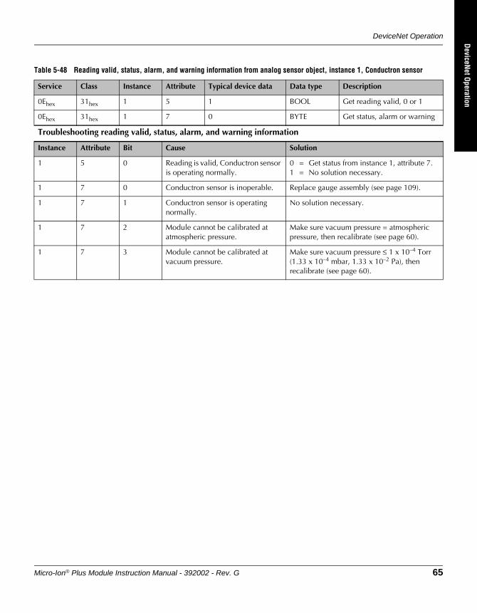
DeviceNet Operation
Micro-Ion® Plus Module Instruction Manual - 392002 - Rev. G 65
DeviceNet OperationRS-485 Operation
Optional DisplayM
aintenance
Table 5-48 Reading valid, status, alarm, and warning information from analog sensor object, instance 1, Conductron sensor
Service Class Instance Attribute Typical device data Data type Description
0Ehex 31hex 1 5 1 BOOL Get reading valid, 0 or 1
0Ehex 31hex 1 7 0 BYTE Get status, alarm or warning
Troubleshooting reading valid, status, alarm, and warning information
Instance Attribute Bit Cause Solution
1 5 0 Reading is valid, Conductron sensor is operating normally.
0 = Get status from instance 1, attribute 7.1 = No solution necessary.
1 7 0 Conductron sensor is inoperable. Replace gauge assembly (see page 109).
1 7 1 Conductron sensor is operating normally.
No solution necessary.
1 7 2 Module cannot be calibrated at atmospheric pressure.
Make sure vacuum pressure = atmospheric pressure, then recalibrate (see page 60).
1 7 3 Module cannot be calibrated at vacuum pressure.
Make sure vacuum pressure ≤ 1 x 10⁻⁴ Torr (1.33 x 10⁻⁴ mbar, 1.33 x 10⁻² Pa), then recalibrate (see page 60).
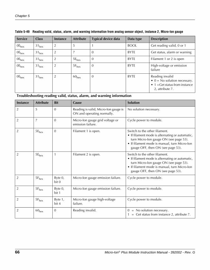
Chapter 5
66 Micro-Ion® Plus Module Instruction Manual - 392002 - Rev. G
Table 5-49 Reading valid, status, alarm, and warning information from analog sensor object, instance 2, Micro-Ion gauge
Service Class Instance Attribute Typical device data Data type Description
0Ehex 31hex 2 5 1 BOOL Get reading valid, 0 or 1
0Ehex 31hex 2 7 0 BYTE Get status, alarm or warning
0Ehex 31hex 2 5Ehex 0 BYTE Filament 1 or 2 is open
0Ehex 31hex 2 5Fhex 0 BYTE High-voltage or emission failure
0Ehex 31hex 2 60hex 0 BYTE Reading invalid• 0 = No solution necessary.• 1 =Get status from instance
2, attribute 7.
Troubleshooting reading valid, status, alarm, and warning information
Instance Attribute Bit Cause Solution
2 5 0 Reading is valid, Micro-Ion gauge is ON and operating normally.
No solution necessary.
2 7 0 Micro-Ion gauge grid voltage or emission failure.
Cycle power to module.
2 5Ehex 0 Filament 1 is open. Switch to the other filament.• If filament mode is alternating or automatic,
turn Micro-Ion gauge ON (see page 53).• If filament mode is manual, turn Micro-Ion
gauge OFF, then ON (see page 53).
2 5Ehex 1 Filament 2 is open. Switch to the other filament.• If filament mode is alternating or automatic,
turn Micro-Ion gauge ON (see page 53).• If filament mode is manual, turn Micro-Ion
gauge OFF, then ON (see page 53).
2 5Fhex Byte 0,bit 0
Micro-Ion gauge emission failure. Cycle power to module.
2 5Fhex Byte 0,bit 1
Micro-Ion gauge emission failure. Cycle power to module.
2 5Fhex Byte 1,bit 4
Micro-Ion gauge high-voltage failure.
Cycle power to module.
2 60hex 0 Reading invalid. 0 = No solution necessary.1 = Get status from instance 2, attribute 7.
Micro-Ion® Plus Module Instruction Manual - 392002 - Rev. G 67
DeviceNet OperationRS-485 Operation
Optional DisplayM
aintenance
Chapter 6 RS-485 Operation
6.1 Pressure output and relay functions
The module has a DeviceNet interface, an RS-485 interface, and one analog output.
• The analog output represents vacuum chamber pressure.
• The module may have no trip point relays, two trip point relays, or three trip point relays. The relays represent vacuum pressure.
You may use RS-485 commands to read vacuum pressure and operate the module.
6.2 Preparing to operatethe module
Before putting the module into operation, you must perform the following procedures:
1. Install the module in accordance with the instructions on pages 15–24.
2. Develop a logic diagram of the process control function.
3. Develop a circuit schematic that specifies exactly how each piece of system hardware will connect to the module relays.
4. Attach a copy of the process control circuit diagram to this manual for future reference and troubleshooting.
5. If the module has two or three trip point relays, use Table 6-1 to record the proposed activation and deactivation trip points (in Torr, mbar, or pascal) and assignments for each relay.
If you need application assistance, phone a Granville-Phillips application engineer:
• Phone 1-303-652-4400 or 1-800-776-6543
• Email: [email protected]
WARNINGUsing the module to measure the pressure of flammable or explosive gases can cause a fire or explosion resulting in severe property damage, personal injury, or death.
Do not use the module to measure the pressure of flammable or explosive gases.
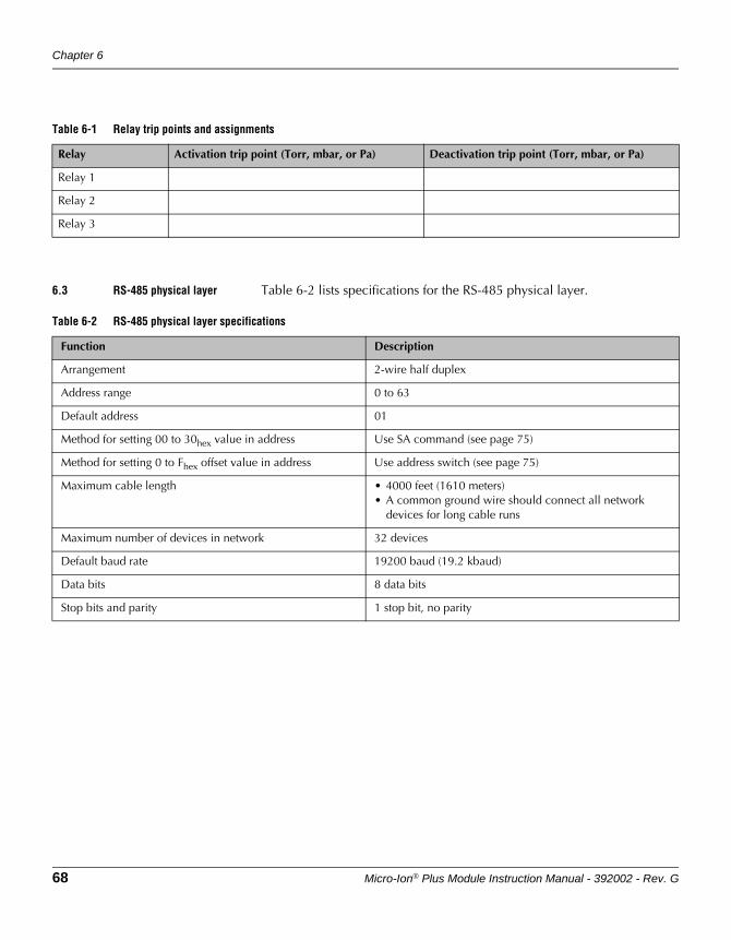
Chapter 6
68 Micro-Ion® Plus Module Instruction Manual - 392002 - Rev. G
6.3 RS-485 physical layer Table 6-2 lists specifications for the RS-485 physical layer.
Table 6-1 Relay trip points and assignments
Relay Activation trip point (Torr, mbar, or Pa) Deactivation trip point (Torr, mbar, or Pa)
Relay 1
Relay 2
Relay 3
Table 6-2 RS-485 physical layer specifications
Function Description
Arrangement 2-wire half duplex
Address range 0 to 63
Default address 01
Method for setting 00 to 30hex value in address Use SA command (see page 75)
Method for setting 0 to Fhex offset value in address Use address switch (see page 75)
Maximum cable length • 4000 feet (1610 meters)• A common ground wire should connect all network
devices for long cable runs
Maximum number of devices in network 32 devices
Default baud rate 19200 baud (19.2 kbaud)
Data bits 8 data bits
Stop bits and parity 1 stop bit, no parity

RS-485 Operation
Micro-Ion® Plus Module Instruction Manual - 392002 - Rev. G 69
DeviceNet OperationRS-485 Operation
Optional DisplayM
aintenance
6.4 Operational tasks Once the module is operating, you may use RS-485 commands to perform the tasks listed in Table 3-4 on page 27.
6.5 Error responses If a command cannot be processed, the module returns one of the error responses listed in Table 6-3.
Table 6-3 RS-485 error responses
Response Possible causes Solution
RANGE ER 1. Pressure value in TS calibration command is outside valid limits.
2. Pressure value in TZ calibration command is outside valid limits.
3. Pressure value in ATM set command is outside valid limits.
4. Ion gauge on-delay time (IDT) is out of range.5. Degas duration (DGT) is out of range.6. Emission current switch point is out of range.7. Relay trip point is out of range (ABS).8. Relay trip point is out of range (DIFF).
1. Make sure atmospheric pressure is > 500 Torr (666 mbar, 6.66 x 10⁴ Pa). See page 91.
2. Make sure vacuum pressure < 3.00 x 10⁻² Torr (3.99 x 10⁻² mbar, 3.99 Pa). See page 92.
3. Make sure the setting is reasonable (250-1000 Torr).
4. Make sure the ion gauge delay time is between 0 and 600 seconds.
5. Make sure the degas duration setting is between 10 and 120 seconds.
6. Make sure current switch point is set correctly. See SER on page 89.
7. Make sure the trip point is between 1E-10 and 1000 Torr, and hysteresis is between 5 and 10,000%.
8. Make sure the trip point is between -800 and +300 Torr, and hysteresis is between 5 and 800 Torr.
SYNTX ER • Command was improperly entered.• Module does not recognize command syntax.• UNL command was sent when software
functions were already unlocked.
• Re-enter command using proper character string (see page 71).
9.99E+09 • Module cannot indicate a valid pressure value.• IG0 command has been sent.
• Send RS or RSX command to determine module status (see page 92).
• If necessary, replace the gauge assembly.• If IG0 command has been sent, send IG1
command (see page 80).
LOCKED Interface function is locked. • Send TLU or UNL command to unlock interface function (see page 74).
INVALID • IG1 command sent while IG ON I/O line not asserted.
• Micro-Ion gauge or Conductron sensor is defective.
• Vacuum pressure is too high for gauge degas.
• Assert the IG ON I/O line or disconnect from ground.
• If the Micro-Ion gauge or Conductron sensor is defective, replace the gauge assembly.
• Decrease the pressure to < 5 x 10⁻⁵ Torr . See DG on page 88.
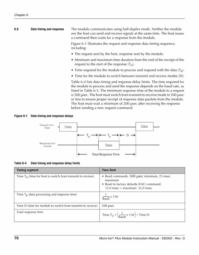
Chapter 6
70 Micro-Ion® Plus Module Instruction Manual - 392002 - Rev. G
6.6 Data timing and response The module communicates using half-duplex mode. Neither the module nor the host can send and receive signals at the same time. The host issues a command then waits for a response from the module.
Figure 6-1 illustrates the request and response data timing sequence, including:
• The request sent by the host, response sent by the module.
• Minimum and maximum time duration from the end of the receipt of the request to the start of the response (TD).
• Time required for the module to process and respond with the data (TR).
• Time for the module to switch between transmit and receive modes (D).
Table 6-4 lists data timing and response delay limits. The time required for the module to process and send the response depends on the baud rate, as listed in Table 6-5. The minimum response time of the module to a request is 500 µsec. The host must switch from transmit to receive mode in 500 µsec or less to ensure proper receipt of response data packets from the module. The host must wait a minimum of 200 µsec after receiving the response before sending a new request command.
Figure 6-1 Data timing and response delays
Table 6-4 Data timing and response delay limits
Timing segment Time limit
Time TD (time for host to switch from transmit to receive) • Read commands: 500 µsec minimum, 25 msec maximum
• Reset to factory defaults (FAC) command:12.0 msec + maximum 32.0 msec
Time TR (data processing and response time)
Time D (time for module to switch from transmit to receive) 200 μsec
Total response time
1Baud------------- 130×
Time TD1
Baud------------- 130× Time D+ +
RS-485 Operation
Micro-Ion® Plus Module Instruction Manual - 392002 - Rev. G 71
DeviceNet OperationRS-485 Operation
Optional DisplayM
aintenance
6.7 RS-485 commands RS-485 commands require entry of integer values, hex code values (such as “0F”), values in engineering notation (such as “2.00E+02”), and alphanumeric character strings.
Command structure Table 6-6 explains the RS-485 command structure. The command should not include a line feed with the carriage return. Including a line feed adds an extra character and may cause a garbled response from the module.
Each response includes 13 characters, beginning with the asterisk (*) or (?) and ending with carriage return (↵).
Symbols used in this manual
The ↵ symbol at the end of the command represents the carriage return (CR), which is entered as hex code 0D or, if you’re using a terminal, by simultaneously pressing the “Control” and “M” keys.
The response will have a space between the address and the text of the response. For example: *02 PROG OK↵.
Table 6-5 Baud rate and data typical response time
Baud rate Data response time (TR)
1200 baud 108 msec
2400 baud 54 msec
4800 baud 27 msec
9600 baud 13.5 msec
19200 baud (default) 6.75 msec
38400 baud 3.3 msec
Table 6-6 RS-485 command structure
Address field Command field Data field Carriage return
#XX Character string for command from host
Character string data required to execute command
↵
“XX” is 2-digit address of module
First character is:• D = Degas• I = Ion gauge• PC = Process control• R = Read• S = Set• T = Calibrate or toggle• U = Unlock• V = Firmware version
Data may include:• Hex code or• Pressure value in engineering
notation or• Alphanumeric character
string
• Enter hex code “0D” or• If using a terminal,
simultaneously press “Control” and “M” keys
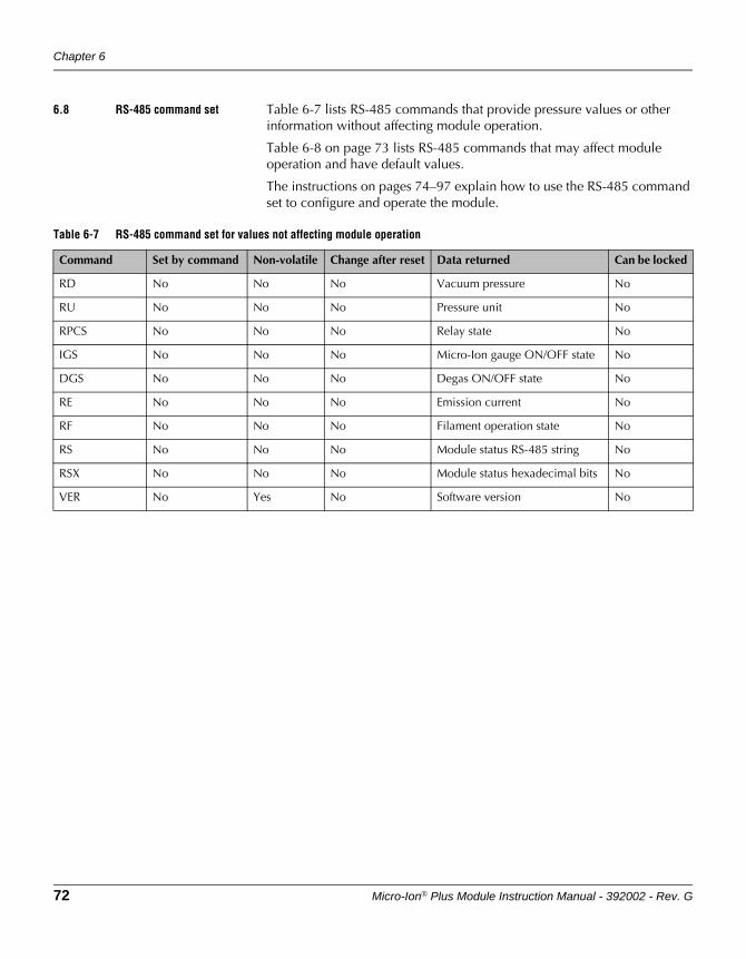
Chapter 6
72 Micro-Ion® Plus Module Instruction Manual - 392002 - Rev. G
6.8 RS-485 command set Table 6-7 lists RS-485 commands that provide pressure values or other information without affecting module operation.
Table 6-8 on page 73 lists RS-485 commands that may affect module operation and have default values.
The instructions on pages 74–97 explain how to use the RS-485 command set to configure and operate the module.
Table 6-7 RS-485 command set for values not affecting module operation
Command Set by command Non-volatile Change after reset Data returned Can be locked
RD No No No Vacuum pressure No
RU No No No Pressure unit No
RPCS No No No Relay state No
IGS No No No Micro-Ion gauge ON/OFF state No
DGS No No No Degas ON/OFF state No
RE No No No Emission current No
RF No No No Filament operation state No
RS No No No Module status RS-485 string No
RSX No No No Module status hexadecimal bits No
VER No Yes No Software version No
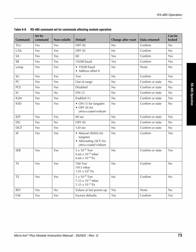
RS-485 Operation
Micro-Ion® Plus Module Instruction Manual - 392002 - Rev. G 73
DeviceNet OperationRS-485 Operation
Optional DisplayM
aintenance
Table 6-8 RS-485 command set for commands affecting module operation
CommandSet by command Non-volatile Default Change after reset Data returned
Can be locked
TLU Yes Yes OFF (0) No Confirm No
UNL Yes Yes OFF (0) No Confirm No
SA Yes Yes 00 Yes Confirm Yes
SB Yes Yes 19200 baud Yes Confirm Yes
yuiop Yes Yes • 19200 baud• Address offset 0
No None No
SU Yes Yes Torr No Confirm Yes
PC Yes Yes Out of range No Confirm or state No
PCE Yes Yes Disabled No Confirm or state No
IG Yes No ON (1) No Confirm or state No
IGM Yes Yes Enabled (1) No Confirm or state Yes
IOD Yes Yes • ON (1) for tungsten• OFF (0) for
yttria-coated iridium
No Confirm or state No
IDT Yes Yes 00 sec No Confirm or state Yes
DG Yes No OFF (0) No Confirm or state No
DGT Yes Yes 120 sec No Confirm or state No
SF Yes Yes • Manual (MAN) for tungsten
• Alternating (ALT) for yttria-coated iridium
No Confirm Yes
SER Yes Yes 5 x 10⁻⁶ Torr6.66 x 10–6 mbar6.66 x 10–4 Pa
No Confirm or state Yes
TS Yes Yes 760 Torr1013 mbar1.01 x 105 Pa
No Confirm No
TZ Yes Yes 1 x 10⁻⁴ Torr1.33 x 10–4 mbar1.33 x 10–2 Pa
No Confirm No
RST Yes No Values at last power-up Yes None No
FAC Yes Yes Factory defaults Yes Confirm Yes
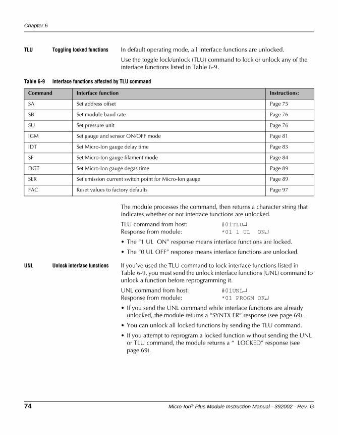
Chapter 6
74 Micro-Ion® Plus Module Instruction Manual - 392002 - Rev. G
TLU Toggling locked functions In default operating mode, all interface functions are unlocked.
Use the toggle lock/unlock (TLU) command to lock or unlock any of the interface functions listed in Table 6-9.
The module processes the command, then returns a character string that indicates whether or not interface functions are unlocked.
TLU command from host: #01TLU↵Response from module: *01 1 UL ON↵
• The “1 UL ON” response means interface functions are locked.
• The “0 UL OFF” response means interface functions are unlocked.
UNL Unlock interface functions If you’ve used the TLU command to lock interface functions listed in Table 6-9, you must send the unlock interface functions (UNL) command to unlock a function before reprogramming it.
UNL command from host: #01UNL↵Response from module: *01 PROGM OK↵
• If you send the UNL command while interface functions are already unlocked, the module returns a “SYNTX ER” response (see page 69).
• You can unlock all locked functions by sending the TLU command.
• If you attempt to reprogram a locked function without sending the UNL or TLU command, the module returns a “ LOCKED” response (see page 69).
Table 6-9 Interface functions affected by TLU command
Command Interface function Instructions:
SA Set address offset Page 75
SB Set module baud rate Page 76
SU Set pressure unit Page 76
IGM Set gauge and sensor ON/OFF mode Page 81
IDT Set Micro-Ion gauge delay time Page 83
SF Set Micro-Ion gauge filament mode Page 84
DGT Set Micro-Ion gauge degas time Page 89
SER Set emission current switch point for Micro-Ion gauge Page 89
FAC Reset values to factory defaults Page 97
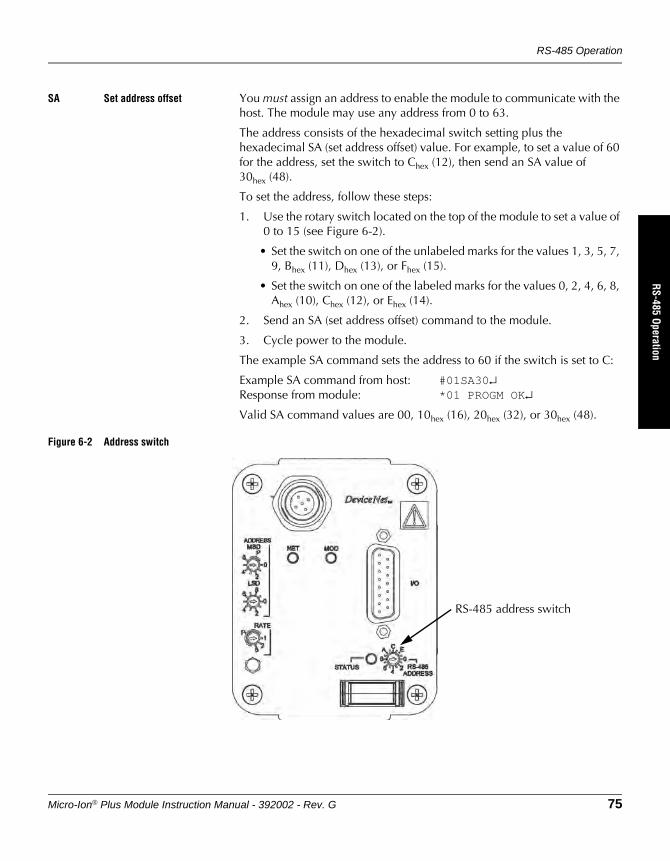
RS-485 Operation
Micro-Ion® Plus Module Instruction Manual - 392002 - Rev. G 75
DeviceNet OperationRS-485 Operation
Optional DisplayM
aintenance
SA Set address offset You must assign an address to enable the module to communicate with the host. The module may use any address from 0 to 63.
The address consists of the hexadecimal switch setting plus the hexadecimal SA (set address offset) value. For example, to set a value of 60 for the address, set the switch to Chex (12), then send an SA value of 30hex (48).
To set the address, follow these steps:
1. Use the rotary switch located on the top of the module to set a value of 0 to 15 (see Figure 6-2).
• Set the switch on one of the unlabeled marks for the values 1, 3, 5, 7, 9, Bhex (11), Dhex (13), or Fhex (15).
• Set the switch on one of the labeled marks for the values 0, 2, 4, 6, 8, Ahex (10), Chex (12), or Ehex (14).
2. Send an SA (set address offset) command to the module.
3. Cycle power to the module.
The example SA command sets the address to 60 if the switch is set to C:
Example SA command from host: #01SA30↵Response from module: *01 PROGM OK↵
Valid SA command values are 00, 10hex (16), 20hex (32), or 30hex (48).
Figure 6-2 Address switch
RS-485 address switch
Chapter 6
76 Micro-Ion® Plus Module Instruction Manual - 392002 - Rev. G
SB Set baud rate The example set baud rate (SB) command sequence sets the baud rate to 2400 baud:
Example SB command from host: #01SB2400↵Response from module: *01 PROGM OK↵
Valid values are 1200, 2400, 4800, 9600, 19200 (default), or 38400 baud.
yuiop Restore RS-485 communication defaults
The lower-case yuiop command restores the address offset to 0 and the baud rate to 19200 baud within the first few seconds after power is applied.
yuiop command from host: yuiop↵Response from module: None
SU Set pressure unit The SU command sets the pressure unit. The example set unit (SU) command sets the pressure unit to Torr:
Example SU command from host: #01SUT↵Response from module: *01 PROGM OK↵
• An SUT command sets the pressure unit to Torr.
• An SUM command sets the pressure unit to mbar.
• An SUP command sets the pressure unit to pascal.
RU Read pressure unit The example read unit (RU) command causes the module to return a character string that identifies Torr as the pressure unit.
RU command from host: #01RU↵Example response from module: *01 TORR ↵
• A “TORR ” response designates Torr as the pressure unit.
• An “MBAR ” response designates mbar as the pressure unit.
• A “pascal” response designates pascal as the pressure unit.
RD Read vacuum pressure The example read pressure (RD) command causes the module to return a value that indicates vacuum pressure is 1.50 x 10⁻²:
Example RD command from host: #01RD↵Example response from module: *01 1.50E–02↵
The returned value is in the pressure unit that you’ve set for the module.
If the returned value is not a valid representation of pressure, see page 104.
RS-485 Operation
Micro-Ion® Plus Module Instruction Manual - 392002 - Rev. G 77
DeviceNet OperationRS-485 Operation
Optional DisplayM
aintenance
PC Process control relay trip points
The module may have two single-pole double-throw (normally open/normally closed) relays or three single-pole single-throw (normally open) relays. Each relay can be independently assigned to vacuum or differential pressure. Each relay has programmable activation and deactivation trip points. The trip point is a programmable value representing pressure at which the relay activates or deactivates.
• When the module is shipped from the factory, relay trip points are out of range, disabled, and will not operate.
• You must configure relays to make them operable.
The example process control (PC) command sequence causes relay 1 to activate when vacuum pressure decreases to 1.01 x 10⁻¹ pressure units and deactivate when vacuum pressure increases to 2.00 x 10⁻¹ pressure units:
Example PC command from host: #01PC1A 1.01E–01↵Response from module: *01 PROGM OK↵
Example PC command from host: #01PC1D 2.00E–01↵Response from module: *01 PROGM OK↵
The “PC1” value identifies process control relay 1.
The + or – that follows the “E” character is the sign of the exponent. For example, a pressure value of “2.00E–2” equals 2 x 10⁻² pressure units, and a pressure value of “2.00E+2” equals 2 x 10² pressure units.
The “A” (activation) and “D” (deactivation) pressure values determine activation and deactivation direction, as listed in Table 6-10.
Table 6-11 lists minimum hysteresis for trip point relays.
Table 6-10 Activation/deactivation direction
Activation versus deactivation Effect on relay operation
If A > D Relay activates with increasing pressure (see Figure 6-4)
If D > A Relay activates with decreasing pressure (see Figure 6-3)
If D = A Software increases “D” value by minimum software defined hysteresis
Table 6-11 Relay minimum hysteresis
Relay assignment Hysteresis
Vacuum pressure 5%
Chapter 6
78 Micro-Ion® Plus Module Instruction Manual - 392002 - Rev. G
Figure 6-3 Default behavior of relays activating with decreasing pressure (A > D)
Figure 6-4 Default behavior of relays activating with increasing pressure (D > A)
Enter the “A” and “D” pressure values in the pressure units you’ve set for the module. See page 77.
To read activation or deactivation pressure for a relay, send a PC command without the pressure value.
Deactivate
Activate
Deactivated
Activated
Time
Vac
uum
cha
mbe
r pr
essu
re
Relay activated
Default 10% hysteresis
Activate
Deactivate
Deactivated
Activated
Relay activated
Time
Vac
uum
cha
mbe
r pr
essu
re
Default 10% hysteresis
RS-485 Operation
Micro-Ion® Plus Module Instruction Manual - 392002 - Rev. G 79
DeviceNet OperationRS-485 Operation
Optional DisplayM
aintenance
The example process control (PC) command sequence causes the module to return values indicating that relay 1 activates at 1.01 x 10⁻¹ pressure units and deactivates at 2.00 x 10⁻¹ pressure units:
Example PC command from host: #01PC1A↵Example response from module: *01 1.01E–01↵
Example PC command from host: #01PC1D↵Example response from module: *01 2.00E–01↵
The “PC1” value identifies relay 1.
The returned value is in the pressure unit that you’ve set for the module.
The “A” or “D” value in the PC command designates the pressure value that is being read:
• The “A” value is the indicated pressure at which the relay activates.
• The “D” value is the indicated pressure at which the relay deactivates.
The same command structure applies to both relays (PC1 and PC2) if the module has two relays, or to all three relays (PC1, PC2, and PC3) if the module has three relays.
PCE Set or read disable/enable state of relays
If relays have been made operable, you may send the process control disable (PCE) command to disable or enable relays.
Example PCE command from host: #01PCE011↵Response from module: *01 PROGM OK↵
The 3-character string following “PCE” disables or enables relays in ascending numerical order.
• A value of 0 disables the specified relay (1, 2, or 3).
• A value of 1 enables the specified relay (1, 2, or 3).
In the example, “0” disables relay 1, and “1” and “1” enable relays 2 and 3.
If you disable a relay, you must re-enable it to make it operable. You must reconfigure the relay to re-enable it. See pages 77–78.
To read disabled/enabled status of relays, send a PCE command without the disable (0) or enable (1) values.
Example PCE command from host: #01PCE↵Example response from module: *01 011↵
The example response means relay 1 is disabled and relays 2 and 3 are enabled.
RPCS Read trip point relay status
The read process control relay status (RPCS) command causes the module to return a numeric value that represents the status of both relays if the module has two relays or all three relays if the module has three relays.
RPCS command from host: #01RPCS↵
Chapter 6
80 Micro-Ion® Plus Module Instruction Manual - 392002 - Rev. G
Example response from module: *01 100↵
• A value of 1 means the specified relay (1, 2, or 3) is activated.
• A value of 0 means the specified relay (1, 2, or 3) is deactivated.
The example response means relay 1 is activated and relays 2 and 3 are deactivated.
IG Turn Micro-Ion gauge ON or OFF
When the module starts up, the Conductron sensor is ON. As pressure decreases to a level that allows the Micro-Ion gauge to operate, the sensor turns the gauge ON. In some instances, you might need to turn the Micro-Ion gauge OFF.
The command includes the alpha characters “I” and “G” and the numeric value 0 (OFF) or 1 (ON).
Send the ion gauge off (IG0) command to turn the Micro-Ion gauge OFF.
IG0 command from host: #01IG0↵Response from module: *01 PROGM OK↵
If you send the IG0 command:
• The response to an RD (read pressure) command depends on the value in the IGM command (see page 81).
• The Micro-Ion gauge remains OFF until you send an IG1 command.
Send the ion gauge on (IG1) command to turn the Micro-Ion gauge ON.
IG1 command from host: #01IG1↵Response from module: *01 PROGM OK↵
If the Micro-Ion gauge is in manual filament mode and one filament is inoperable, you must switch to the other filament by sending the IG0 command, then sending the IG1 command (see page 91).
IGS Read Micro-Ion gauge ON/OFF status
If you send the ion gauge status (IGS) command, the module returns a character string that indicates the ON/OFF status of the Micro-Ion gauge.
IGS command from host: #01IGS↵Example response from module: *01 1 IG ON↵
• The “1 IG ON” response means the Micro-Ion gauge is ON.
• The “0 IG OFF” response means the Micro-Ion gauge is OFF.
RS-485 Operation
Micro-Ion® Plus Module Instruction Manual - 392002 - Rev. G 81
DeviceNet OperationRS-485 Operation
Optional DisplayM
aintenance
IGM Set or read pressure indication when Micro-Ion gauge is OFF
If the Micro-Ion gauge was turned OFF using the IG0 command or wiring terminals 3 and 5, use the IGM (ion gauge mode) command to enable or disable pressure indications from the Conductron sensor.
Example IGM command from host: #01IGM1↵Response from module: *01 PROGM OK↵
The command includes the alpha characters “I”, “G”, and “M” and the alphanumeric 0, 1, or “S” switch.
• The 1 switch enables pressure indications from the Conductron sensor while the Micro-Ion gauge is turned OFF.
• The 0 switch disables pressure indications from the Conductron sensor while the Micro-Ion gauge is turned OFF.
Use the “S” switch to read the pressure output configuration.
IGMS command from host: #01IGMS↵Example response from module: *01 0 ALL↵
• The “0 ALL” character string means all pressure indications are disabled when the Micro-Ion gauge is turned OFF.
• The “0 IG” character string means pressure indications are enabled when the Micro-Ion gauge is turned OFF.
Chapter 6
82 Micro-Ion® Plus Module Instruction Manual - 392002 - Rev. G
IOD Set or read Micro-Ion gauge delay ON/OFF state
The ion gauge delay (IOD) command reduces the possibility that the Micro-Ion gauge filaments will burn out if the gauge turns ON at a pressure that is too high. The IOD command delays the time at which the Micro-Ion gauge turns ON with decreasing pressure.
If the IOD command is set to ON, at initial startup, the module software determines how long the Micro-Ion gauge should wait to turn ON after pressure has decreased to a point where the gauge can operate.
The command includes the alpha characters “I”, “O”, and “D” and the numeric value 0 (OFF) or 1 (ON).
The example IOD command sets the delay time to OFF. (The Micro-Ion gauge turns ON, without delay, at the pressure at which the gauge can operate.)
Example IOD command from host: #01IOD0↵Response from module: *01 PROGM OK↵
• if the Micro-Ion gauge has tungsten filaments, the default setting for the IOD command is ON (1).
• If the Micro-Ion gauge has yttria-coated iridium filaments, the default setting for the IOD command is OFF (0).
If the gauge assembly is replaced, the module software automatically sets the Micro-Ion gauge delay state according to the filament material.
During the delay, outputs indicate pressure as measured by the Conductron sensor.
If you send the IOD command without the ON or OFF value, the module returns a character string that represents the Micro-Ion delay ON/OFF state.
IOD command from host: #01IOD↵Example response from module: *01 1 ON↵
• The “1 ON” response means the Micro-Ion gauge delay is ON.
• The “0 OFF” response means the Micro-Ion gauge delay is OFF.
If the IOD command is set to ON (1), within the pressure range of 1.00 x 10⁻³ to 3.00 x 10⁻² Torr (1.33 x 10⁻³ to 39.9 x 10⁻² mbar, 1.33 to 3.99 Pa), the pressure output might not be within the specified accuracy of ± 15% of reading.
Whether or not the IOD command is set to ON (1), some signal fluctuation occurs if the Micro-Ion gauge has tungsten filaments.
RS-485 Operation
Micro-Ion® Plus Module Instruction Manual - 392002 - Rev. G 83
DeviceNet OperationRS-485 Operation
Optional DisplayM
aintenance
IDT Set or read Micro-Ion gauge delay time
Whether or not the IOD command is set to ON, you may send the ion delay time (IDT) command to add to, determine, or read the amount of time the Micro-Ion gauge waits to turn ON after pressure has decreased to a point where the gauge can operate.
The example IDT command sets the delay time to 20 seconds.
Example IDT command from host: #01IDT 20↵Response from module: *01 PROGM OK↵
• The command includes the alpha characters “I”, “D”, and “T” and the numeric value representing the number of seconds.
• Valid values are 0 to 600 seconds.
If the IOD command is set to ON (1), the number of seconds specified in the IDT command is added to the time the module software has determined that the Micro-Ion gauge should wait to turn ON with decreasing pressure, as expressed in the following equation:
If the IOD command is set to OFF (0), the number of seconds specified in the IDT command is the exact amount of time that the Micro-Ion gauge will wait to turn ON with decreasing pressure.
If you send the IDT command without the time value, the module returns a character string that represents the Micro-Ion gauge delay time.
DGT command from host: #01IDT↵Example response from module: *01 60 IDT↵
The example response means the delay time is set to 60 seconds. If the IOD command is set to ON (1), the response does not include the delay time determined by the module software.
During the delay, outputs indicate pressure as measured by the Conductron sensor.
If the gauge assembly is replaced, the module software automatically sets the Micro-Ion gauge delay time according to the filament material.
• If the replacement gauge contains tungsten filaments, the Micro-Ion gauge waits an additional 2 seconds, beyond software-defined delay time, to turn ON with decreasing pressure.
• If the replacement gauge contains yttria-coated iridium filaments, the Micro-Ion gauge turns ON, without delay, as soon as operational pressure is achieved with decreasing pressure.
Total time delay TimeIOD TimeIDT+=
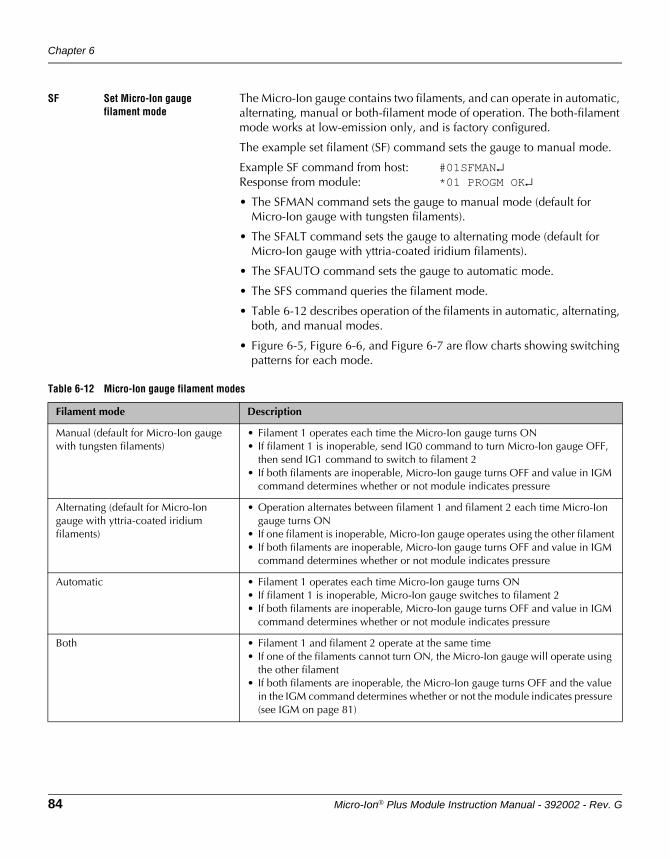
Chapter 6
84 Micro-Ion® Plus Module Instruction Manual - 392002 - Rev. G
SF Set Micro-Ion gauge filament mode
The Micro-Ion gauge contains two filaments, and can operate in automatic, alternating, manual or both-filament mode of operation. The both-filament mode works at low-emission only, and is factory configured.
The example set filament (SF) command sets the gauge to manual mode.
Example SF command from host: #01SFMAN↵Response from module: *01 PROGM OK↵
• The SFMAN command sets the gauge to manual mode (default for Micro-Ion gauge with tungsten filaments).
• The SFALT command sets the gauge to alternating mode (default for Micro-Ion gauge with yttria-coated iridium filaments).
• The SFAUTO command sets the gauge to automatic mode.
• The SFS command queries the filament mode.
• Table 6-12 describes operation of the filaments in automatic, alternating, both, and manual modes.
• Figure 6-5, Figure 6-6, and Figure 6-7 are flow charts showing switching patterns for each mode.
Table 6-12 Micro-Ion gauge filament modes
Filament mode Description
Manual (default for Micro-Ion gauge with tungsten filaments)
• Filament 1 operates each time the Micro-Ion gauge turns ON• If filament 1 is inoperable, send IG0 command to turn Micro-Ion gauge OFF,
then send IG1 command to switch to filament 2• If both filaments are inoperable, Micro-Ion gauge turns OFF and value in IGM
command determines whether or not module indicates pressure
Alternating (default for Micro-Ion gauge with yttria-coated iridium filaments)
• Operation alternates between filament 1 and filament 2 each time Micro-Ion gauge turns ON
• If one filament is inoperable, Micro-Ion gauge operates using the other filament• If both filaments are inoperable, Micro-Ion gauge turns OFF and value in IGM
command determines whether or not module indicates pressure
Automatic • Filament 1 operates each time Micro-Ion gauge turns ON• If filament 1 is inoperable, Micro-Ion gauge switches to filament 2• If both filaments are inoperable, Micro-Ion gauge turns OFF and value in IGM
command determines whether or not module indicates pressure
Both • Filament 1 and filament 2 operate at the same time• If one of the filaments cannot turn ON, the Micro-Ion gauge will operate using
the other filament• If both filaments are inoperable, the Micro-Ion gauge turns OFF and the value
in the IGM command determines whether or not the module indicates pressure (see IGM on page 81)

RS-485 Operation
Micro-Ion® Plus Module Instruction Manual - 392002 - Rev. G 85
DeviceNet OperationRS-485 Operation
Optional DisplayM
aintenance
Figure 6-5 Automatic filament switching flow chart
NOTE: The Micro-Ion Module is factory configured for either single-filament or both-filament operation at low emisson.
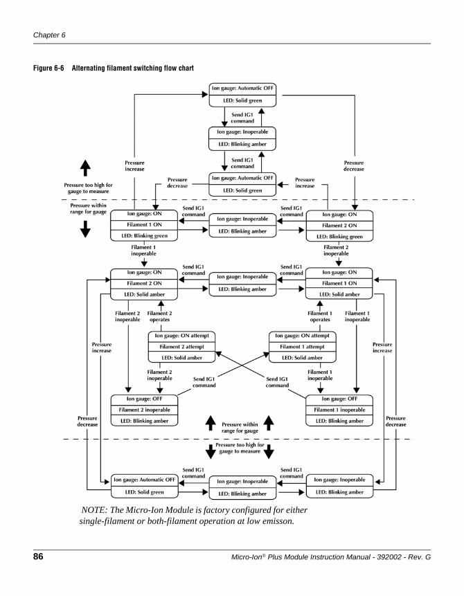
Chapter 6
86 Micro-Ion® Plus Module Instruction Manual - 392002 - Rev. G
Figure 6-6 Alternating filament switching flow chart
NOTE: The Micro-Ion Module is factory configured for either single-filament or both-filament operation at low emisson.
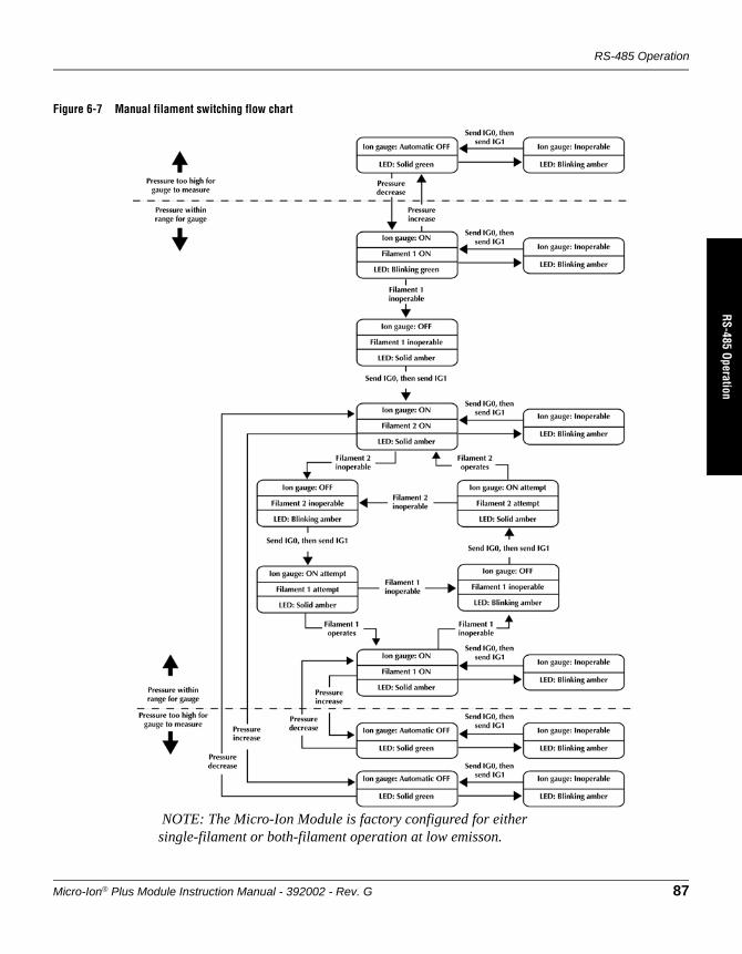
RS-485 Operation
Micro-Ion® Plus Module Instruction Manual - 392002 - Rev. G 87
DeviceNet OperationRS-485 Operation
Optional DisplayM
aintenance
Figure 6-7 Manual filament switching flow chart
NOTE: The Micro-Ion Module is factory configured for either single-filament or both-filament operation at low emisson.
Chapter 6
88 Micro-Ion® Plus Module Instruction Manual - 392002 - Rev. G
RF Read Micro-Ion gauge filament status
The read filament (RF) command causes the module to return an example character string indicating filament 1 is operating.
RF command from host: #01RF↵Example response from module: *01 FIL SF1↵
• The “FIL SF1” response means filament 1 is operating.
• The “FIL SF2” response means filament 2 is operating.
• The "FIL SFB" response means both filaments (1 & 2) are operating.
DG Degas Micro-Ion gauge Use degas gauge (DG) commands to initiate or terminate a Micro-Ion gauge degas cycle, read the degas ON/OFF state, or set the gauge degas time.
The command includes the alpha characters “D” and “G” and the numeric value 0 (terminate) or 1 (initiate).
To degas the Micro-Ion gauge, follow these steps:
1. Turn the Micro-Ion gauge ON. (see page 81)
2. Make sure vacuum pressure is lower than 5 x 10⁻⁵ Torr (6.66 x 10⁻⁵ mbar, 6.66 x 10⁻³ Pa).
3. Send the degas gauge initiate (DG1) command to initiate the Micro-Ion gauge degas cycle. The default time for gauge degas is two minutes.
DG1 command from host: #01DG1↵Response from module: *01 PROGM OK↵
4. If you wish to terminate the Micro-Ion gauge degas cycle before it is completed, send the degas gauge terminate (DG0) command.
DG0 command from host: #01DG0↵Response from module: *01 PROGM OK↵
DGS Read Micro-Ion gauge degas status
At any time, you may send the degas gauge status (DGS) command to read the Micro-Ion gauge degas state.
DGS command from host: #01DGS↵Example response from module: *01 1 DG ON↵
• The “1 DG ON” response means a degas cycle is in progress.
• The “0 DG OFF” response means gauge degas is OFF.
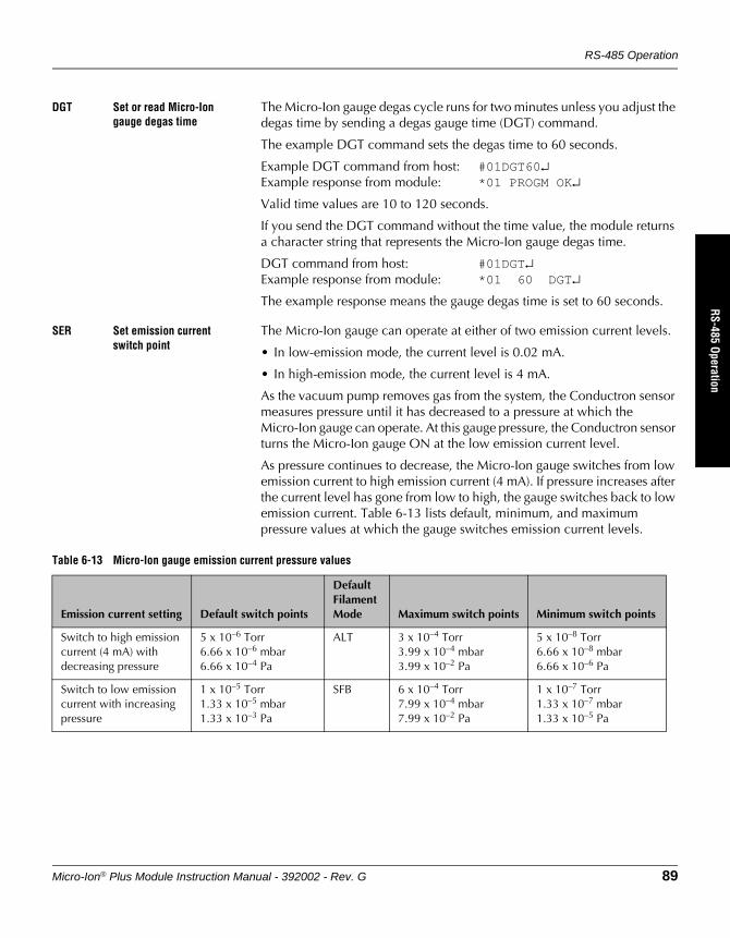
RS-485 Operation
Micro-Ion® Plus Module Instruction Manual - 392002 - Rev. G 89
DeviceNet OperationRS-485 Operation
Optional DisplayM
aintenance
DGT Set or read Micro-Ion gauge degas time
The Micro-Ion gauge degas cycle runs for two minutes unless you adjust the degas time by sending a degas gauge time (DGT) command.
The example DGT command sets the degas time to 60 seconds.
Example DGT command from host: #01DGT60↵Example response from module: *01 PROGM OK↵
Valid time values are 10 to 120 seconds.
If you send the DGT command without the time value, the module returns a character string that represents the Micro-Ion gauge degas time.
DGT command from host: #01DGT↵Example response from module: *01 60 DGT↵
The example response means the gauge degas time is set to 60 seconds.
SER Set emission current switch point
The Micro-Ion gauge can operate at either of two emission current levels.
• In low-emission mode, the current level is 0.02 mA.
• In high-emission mode, the current level is 4 mA.
As the vacuum pump removes gas from the system, the Conductron sensor measures pressure until it has decreased to a pressure at which the Micro-Ion gauge can operate. At this gauge pressure, the Conductron sensor turns the Micro-Ion gauge ON at the low emission current level.
As pressure continues to decrease, the Micro-Ion gauge switches from low emission current to high emission current (4 mA). If pressure increases after the current level has gone from low to high, the gauge switches back to low emission current. Table 6-13 lists default, minimum, and maximum pressure values at which the gauge switches emission current levels.
Table 6-13 Micro-Ion gauge emission current pressure values
Emission current setting Default switch points
Default Filament Mode Maximum switch points Minimum switch points
Switch to high emission current (4 mA) with decreasing pressure
5 x 10⁻⁶ Torr6.66 x 10–6 mbar6.66 x 10–4 Pa
ALT 3 x 10⁻⁴ Torr3.99 x 10–4 mbar3.99 x 10–2 Pa
5 x 10⁻⁸ Torr6.66 x 10–8 mbar6.66 x 10–6 Pa
Switch to low emission current with increasing pressure
1 x 10⁻⁵ Torr1.33 x 10–5 mbar1.33 x 10–3 Pa
SFB 6 x 10⁻⁴ Torr7.99 x 10–4 mbar7.99 x 10–2 Pa
1 x 10⁻⁷ Torr1.33 x 10–7 mbar1.33 x 10–5 Pa
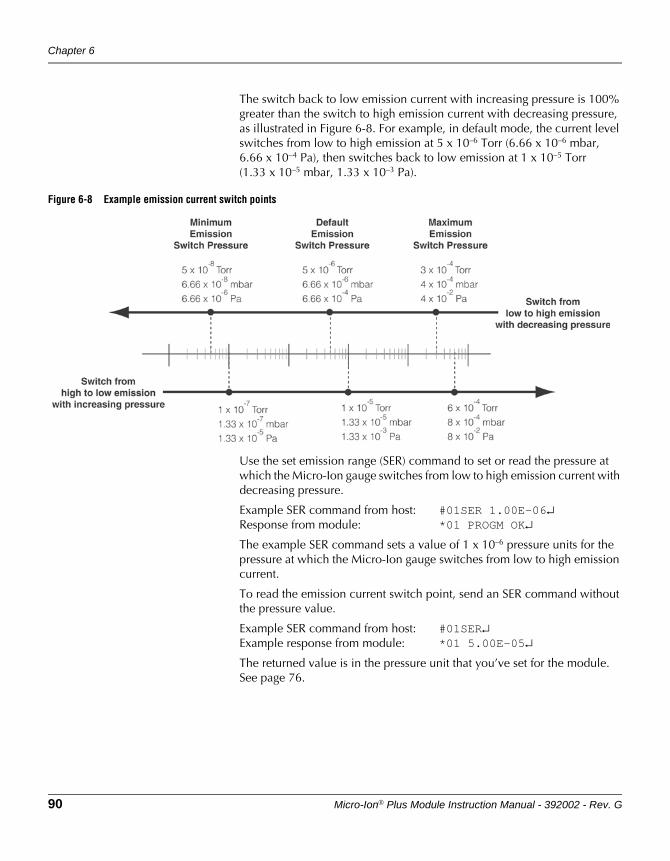
Chapter 6
90 Micro-Ion® Plus Module Instruction Manual - 392002 - Rev. G
The switch back to low emission current with increasing pressure is 100% greater than the switch to high emission current with decreasing pressure, as illustrated in Figure 6-8. For example, in default mode, the current level switches from low to high emission at 5 x 10⁻⁶ Torr (6.66 x 10⁻⁶ mbar, 6.66 x 10⁻⁴ Pa), then switches back to low emission at 1 x 10⁻⁵ Torr (1.33 x 10⁻⁵ mbar, 1.33 x 10⁻³ Pa).
Figure 6-8 Example emission current switch points
Use the set emission range (SER) command to set or read the pressure at which the Micro-Ion gauge switches from low to high emission current with decreasing pressure.
Example SER command from host: #01SER 1.00E–06↵Response from module: *01 PROGM OK↵
The example SER command sets a value of 1 x 10⁻⁶ pressure units for the pressure at which the Micro-Ion gauge switches from low to high emission current.
To read the emission current switch point, send an SER command without the pressure value.
Example SER command from host: #01SER↵Example response from module: *01 5.00E–05↵
The returned value is in the pressure unit that you’ve set for the module. See page 76.
RS-485 Operation
Micro-Ion® Plus Module Instruction Manual - 392002 - Rev. G 91
DeviceNet OperationRS-485 Operation
Optional DisplayM
aintenance
RE Read Micro-Ion gauge emission current
Send the read emission (RE) command to read the Micro-Ion gauge emission current.
RE command from host: #01RE↵Example response from module: *01 4.0MA EM↵
Table 6-14 lists module responses to the RE command.
TS Calibrate module at atmospheric pressure
Atmospheric pressure calibration and differential pressure zero are performed using N2 at the factory before the module is shipped. Differential pressure zero is the pressure value at which atmospheric and vacuum pressures are equal. The factory calibration sets the differential pressure zero to approximately 760 Torr (1013 mbar, 1.01 x 10⁵ Pa). The module will not operate properly unless you reset the atmospheric pressure calibration and differential pressure zero at the ambient operating pressure.
If the atmospheric pressure calibration value is too low, the Micro-Ion gauge will not turn ON.
Use N2 or air to calibrate the module at atmospheric pressure. Minimum valid calibration pressure is 500 Torr (666 mbar, 6.66 x 10⁴ Pa).
1. Shut the pump OFF and, using N2 or air, allow the vacuum pressure to increase until it equals atmospheric pressure.
2. Send a calibration at system pressure (TS) command.
Example TS command from host: #01TS↵Example response from module: *01 PROGM OK↵
If the module returns a message other than “PROGM OK” in response to the TS command, the atmospheric calibration has failed. See page 104 to troubleshoot the problem.
Table 6-14 Responses to RE command
Response Description
4.0 mA EM Micro-Ion gauge is in high-emission mode (4.0 mA current)
0.02 mA EM Micro-Ion gauge is in low-emission mode (0.02 mA current)
15 mA EM Micro-Ion gauge degas cycle is in progress (see page 88)
0 IG OFF Micro-Ion gauge is OFF (see page 80)
Chapter 6
92 Micro-Ion® Plus Module Instruction Manual - 392002 - Rev. G
TZ Calibrate module at vacuum pressure
Ordinarily, the Conductron sensor turns the Micro-Ion gauge ON when pressure decreases to 2 x 10⁻² Torr (2.66 x 10⁻² mbar, 2.66 Pa). However, if the Conductron sensor calibration has shifted so that the Micro-Ion gauge cannot turn ON, you can recalibrate the module for vacuum pressure.
Use N2 or air to calibrate the module at vacuum pressure. Maximum valid calibration pressure is 3.00 x 10⁻² Torr (3.99 x 10⁻² mbar, 3.99 Pa).
1. Turn the pump ON and, using N2 or air, allow the vacuum chamber to decrease to the optimal calibration pressure of 1 x 10⁻⁴ Torr (1.33 x 10⁻⁴ mbar, 1.33 x 10⁻² Pa) or a lower pressure.
2. Send the calibration at vacuum pressure (TZ) command.
Example TZ command from host: #01TZ↵Example response from module: *01 PROGM OK↵
If the module returns a message other than “PROGM OK” in response to the TZ command, the vacuum pressure calibration has failed. See page 104 to troubleshoot the problem.
RS Read module status RS-485 strings
Send the read status (RS) command to read RS-485 character strings that indicate the module operating status.
RS command from host: #01RS↵Example response from module: *01 00 ST OK↵
The example response indicates the module is operating normally.
Table 6-15 lists module responses to the RS command. To find out if more than one status condition exists, send another RS command. Repeatedly sending the RS command causes the responses to cycle through the entire list of existing status conditions as many times as necessary while you diagnose and remedy all existing status conditions.
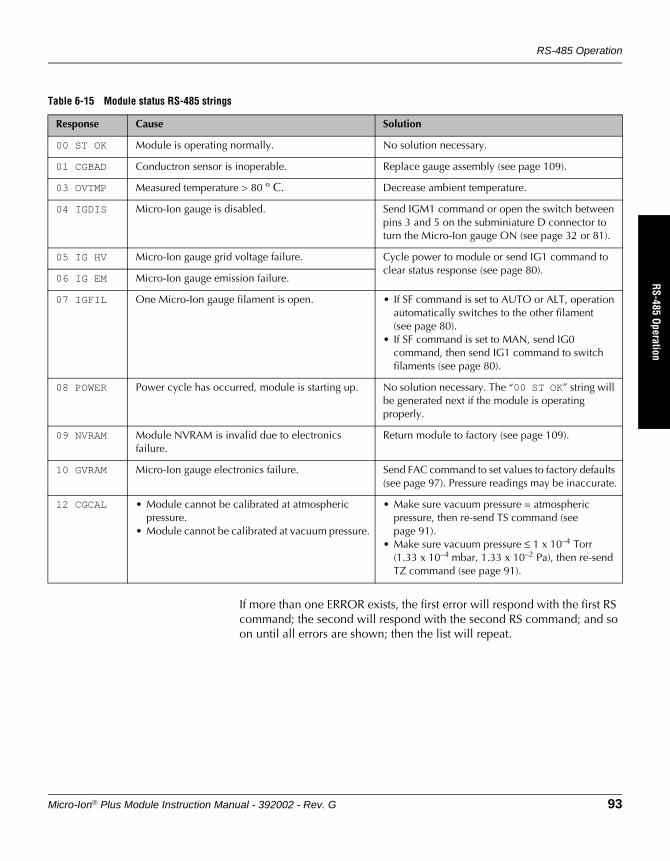
RS-485 Operation
Micro-Ion® Plus Module Instruction Manual - 392002 - Rev. G 93
DeviceNet OperationRS-485 Operation
Optional DisplayM
aintenance
If more than one ERROR exists, the first error will respond with the first RS command; the second will respond with the second RS command; and so on until all errors are shown; then the list will repeat.
Table 6-15 Module status RS-485 strings
Response Cause Solution
00 ST OK Module is operating normally. No solution necessary.
01 CGBAD Conductron sensor is inoperable. Replace gauge assembly (see page 109).
03 OVTMP Measured temperature > 80 º C. Decrease ambient temperature.
04 IGDIS Micro-Ion gauge is disabled. Send IGM1 command or open the switch between pins 3 and 5 on the subminiature D connector to turn the Micro-Ion gauge ON (see page 32 or 81).
05 IG HV Micro-Ion gauge grid voltage failure. Cycle power to module or send IG1 command to clear status response (see page 80).
06 IG EM Micro-Ion gauge emission failure.
07 IGFIL One Micro-Ion gauge filament is open. • If SF command is set to AUTO or ALT, operation automatically switches to the other filament (see page 80).
• If SF command is set to MAN, send IG0 command, then send IG1 command to switch filaments (see page 80).
08 POWER Power cycle has occurred, module is starting up. No solution necessary. The “00 ST OK” string will be generated next if the module is operating properly.
09 NVRAM Module NVRAM is invalid due to electronics failure.
Return module to factory (see page 109).
10 GVRAM Micro-Ion gauge electronics failure. Send FAC command to set values to factory defaults (see page 97). Pressure readings may be inaccurate.
12 CGCAL • Module cannot be calibrated at atmospheric pressure.
• Module cannot be calibrated at vacuum pressure.
• Make sure vacuum pressure = atmospheric pressure, then re-send TS command (see page 91).
• Make sure vacuum pressure ≤ 1 x 10⁻⁴ Torr (1.33 x 10⁻⁴ mbar, 1.33 x 10⁻² Pa), then re-send TZ command (see page 91).
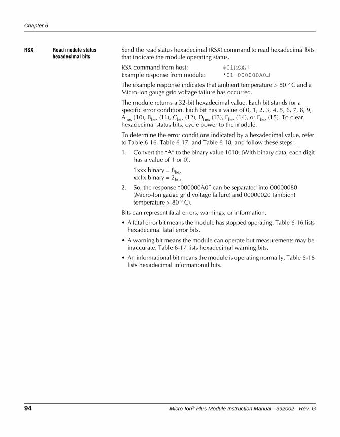
Chapter 6
94 Micro-Ion® Plus Module Instruction Manual - 392002 - Rev. G
RSX Read module status hexadecimal bits
Send the read status hexadecimal (RSX) command to read hexadecimal bits that indicate the module operating status.
RSX command from host: #01RSX↵Example response from module: *01 000000A0↵
The example response indicates that ambient temperature > 80 º C and a Micro-Ion gauge grid voltage failure has occurred.
The module returns a 32-bit hexadecimal value. Each bit stands for a specific error condition. Each bit has a value of 0, 1, 2, 3, 4, 5, 6, 7, 8, 9, Ahex (10), Bhex (11), Chex (12), Dhex (13), Ehex (14), or Fhex (15). To clear hexadecimal status bits, cycle power to the module.
To determine the error conditions indicated by a hexadecimal value, refer to Table 6-16, Table 6-17, and Table 6-18, and follow these steps:
1. Convert the “A” to the binary value 1010. (With binary data, each digit has a value of 1 or 0).
1xxx binary = 8hexxx1x binary = 2hex
2. So, the response “000000A0” can be separated into 00000080 (Micro-Ion gauge grid voltage failure) and 00000020 (ambient temperature > 80 º C).
Bits can represent fatal errors, warnings, or information.
• A fatal error bit means the module has stopped operating. Table 6-16 lists hexadecimal fatal error bits.
• A warning bit means the module can operate but measurements may be inaccurate. Table 6-17 lists hexadecimal warning bits.
• An informational bit means the module is operating normally. Table 6-18 lists hexadecimal informational bits.
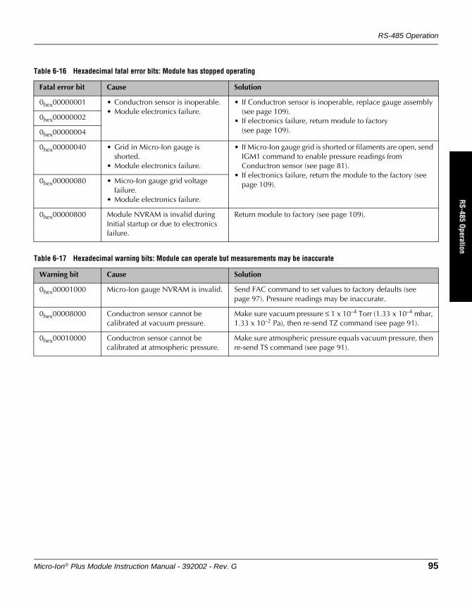
RS-485 Operation
Micro-Ion® Plus Module Instruction Manual - 392002 - Rev. G 95
DeviceNet OperationRS-485 Operation
Optional DisplayM
aintenance
Table 6-16 Hexadecimal fatal error bits: Module has stopped operating
Fatal error bit Cause Solution
0hex00000001 • Conductron sensor is inoperable.• Module electronics failure.
• If Conductron sensor is inoperable, replace gauge assembly (see page 109).
• If electronics failure, return module to factory (see page 109).
0hex00000002
0hex00000004
0hex00000040 • Grid in Micro-Ion gauge is shorted.
• Module electronics failure.
• If Micro-Ion gauge grid is shorted or filaments are open, send IGM1 command to enable pressure readings from Conductron sensor (see page 81).
• If electronics failure, return the module to the factory (see page 109).0hex00000080 • Micro-Ion gauge grid voltage
failure.• Module electronics failure.
0hex00000800 Module NVRAM is invalid during Initial startup or due to electronics failure.
Return module to factory (see page 109).
Table 6-17 Hexadecimal warning bits: Module can operate but measurements may be inaccurate
Warning bit Cause Solution
0hex00001000 Micro-Ion gauge NVRAM is invalid. Send FAC command to set values to factory defaults (see page 97). Pressure readings may be inaccurate.
0hex00008000 Conductron sensor cannot be calibrated at vacuum pressure.
Make sure vacuum pressure ≤ 1 x 10⁻⁴ Torr (1.33 x 10⁻⁴ mbar, 1.33 x 10⁻² Pa), then re-send TZ command (see page 91).
0hex00010000 Conductron sensor cannot be calibrated at atmospheric pressure.
Make sure atmospheric pressure equals vacuum pressure, then re-send TS command (see page 91).
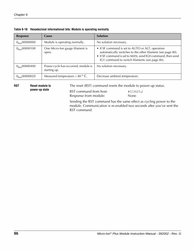
Chapter 6
96 Micro-Ion® Plus Module Instruction Manual - 392002 - Rev. G
RST Reset module to power-up state
The reset (RST) command resets the module to power-up status.
RST command from host: #01RST↵Response from module: None
Sending the RST command has the same effect as cycling power to the module. Communication is re-enabled two seconds after you’ve sent the RST command.
Table 6-18 Hexadecimal informational bits: Module is operating normally
Response Cause Solution
0hex00000000 Module is operating normally. No solution necessary.
0hex00000100 One Micro-Ion gauge filament is open.
• If SF command is set to AUTO or ALT, operation automatically switches to the other filament (see page 80).
• If SF command is set to MAN, send IG0 command, then send IG1 command to switch filaments (see page 80).
0hex00000400 Power cycle has occurred, module is starting up.
No solution necessary.
0hex00000020 Measured temperature > 80 º C. Decrease ambient temperature.
RS-485 Operation
Micro-Ion® Plus Module Instruction Manual - 392002 - Rev. G 97
DeviceNet OperationRS-485 Operation
Optional DisplayM
aintenance
FAC Reset values to factory defaults
Table 6-19 lists default settings for the module. After you’ve reconfigured the module, you may restore parameters to their default values by sending a factory reset (FAC) command.
FAC command from host: #01FAC↵Response from module: *01 PROGM OK↵
Reset command from host: #01RST↵Response from module: None
VER Read firmware version The read firmware version (VER) command causes the module to return a value that represents the internal part number and firmware version for the module. The example response indicates the internal part number is 16781 and the firmware version is 07
VER command from host: #01VER↵Example response from module: *01 16781–11↵
• The first five digits (preceding the dash) are the internal part number.
• The last two digits (following the dash) are the firmware version.
Table 6-19 Factory default settings affected by FAC command
Parameter Default Setting
Digital communication Baud rate: 19200 baud
Vacuum calibration pressure 1 x 10⁻⁴ Torr (1.33 x 10⁻⁴ mbar, 1.33 x 10⁻² Pa)
Atmospheric calibration pressure 760 Torr (1013 mbar, 1.01 x 10⁵ Pa)
Differential pressure zero 760 Torr (1013 mbar, 1.01 x 10⁵ Pa)
Micro-Ion gauge emission current switch point • With decreasing pressure:5 x 10⁻⁶ Torr6.66 x 10–6 mbar6.66 x 10–4 Pa
• With increasing pressure:1 x 10⁻⁵ Torr1.33 x 10–5 mbar1.33 x 10–3 Pa
Locked interface functions OFF

Chapter 6
98 Micro-Ion® Plus Module Instruction Manual - 392002 - Rev. G
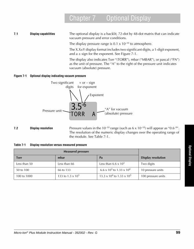
Micro-Ion® Plus Module Instruction Manual - 392002 - Rev. G 99
DeviceNet OperationRS-485 Operation
Optional DisplayM
aintenance
Chapter 7 Optional Display
7.1 Display capabilities The optional display is a backlit, 72-dot by 48-dot matrix that can indicate vacuum pressure and error conditions.
The display pressure range is 0.1 x 10⁻¹⁰ to atmosphere.
The X.X±Y display format includes two significant digits, a 1-digit exponent, and a ± sign for the exponent. See Figure 7-1.
The display also indicates Torr “(TORR”), mbar (“MBAR”), or pascal (“PA”) as the unit of pressure. The “A” to the right of the pressure unit indicates vacuum (absolute) pressure.
Figure 7-1 Optional display indicating vacuum pressure
7.2 Display resolution Pressure values in the 10–10 range (such as 6 x 10⁻¹⁰) will appear as “0.6–9”. The resolution of the numeric display changes over the operating range of the module. See Table 7-1.
Two significantdigits
+ or – signfor exponent
Exponent
Pressure unit3.5-6
TORR A“A” for vacuum (absolute) pressure
Table 7-1 Display resolution versus measured pressure
Measured pressure
Display resolutionTorr mbar Pa
Less than 50 Less than 66 Less than 6.6 x 10³ Two digits
50 to 100 66 to 133 6.6 x 10³ to 1.33 x 10⁴ 10 pressure units
100 to 1000 133 to 1.3 x 10³ 13.3 x 10⁴ to 1.33 x 10⁵ 100 pressure units
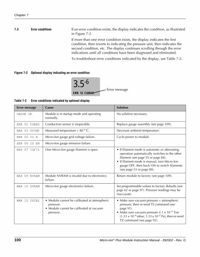
Chapter 7
100 Micro-Ion® Plus Module Instruction Manual - 392002 - Rev. G
7.3 Error conditions If an error condition exists, the display indicates the condition, as illustrated in Figure 7-2.
If more than one error condition exists, the display indicates the first condition, then reverts to indicating the pressure unit, then indicates the second condition, etc. The display continues scrolling through the error indications until all conditions have been diagnosed and eliminated.
To troubleshoot error conditions indicated by the display, see Table 7-2.
Figure 7-2 Optional display indicating an error condition
3.5-6
ERR 12 CGBADError message
Table 7-2 Error conditions indicated by optional display
Error message Cause Solution
GAUGE OK Module is in startup mode and operating normally.
No solution necessary.
ERR 01 CGBAD Conductron sensor is inoperable. Replace gauge assembly (see page 109).
WAR 03 OVTMP Measured temperature > 80 º C. Decrease ambient temperature.
ERR 05 IG H Micro-Ion gauge grid voltage failure. Cycle power to module.
ERR 06 IG EM Micro-Ion gauge emission failure.
WAR 07 IGFIL One Micro-Ion gauge filament is open. • If filament mode is automatic or alternating, operation automatically switches to the other filament (see page 55 or page 84).
• If filament mode is manual, turn Micro-Ion gauge OFF, then back ON to switch filaments (see page 53 or page 80).
WAR 09 NVRAM Module NVRAM is invalid due to electronics failure.
Return module to factory (see page 109).
WAR 10 GVRAM Micro-Ion gauge electronics failure. Set programmable values to factory defaults (see page 62 or page 97). Pressure readings may be inaccurate.
WAR 12 CGCAL • Module cannot be calibrated at atmospheric pressure.
• Module cannot be calibrated at vacuum pressure.
• Make sure vacuum pressure = atmospheric pressure, then re-send TS command (see page 91).
• Make sure vacuum pressure ≤ 1 x 10⁻⁴ Torr (1.33 x 10⁻⁴ mbar, 1.33 x 10⁻² Pa), then re-send TZ command (see page 92).
Micro-Ion® Plus Module Instruction Manual - 392002 - Rev. G 101
DeviceNet OperationRS-485 Operation
Optional DisplayM
aintenance
Chapter 8 Maintenance
8.1 Customer service For Customer Service or Technical Support 24 hours per day, 7 days per week, every day of the year including holidays:
Phone: +1-800-227-8766 or +1-303-652-4691
Email: [email protected]
MKS, Granville-Phillips Division6450 Dry Creek ParkwayLongmont, CO 80503 USAPhone: 1-303-652-4691 or 1-800-776-6543 FAX: 1-303-652-2844
Damage requiring service Shut OFF power to the module and refer servicing to qualified service personnel under the following conditions:
• The product has been exposed to rain or water.
• The product does not operate normally, even if you have followed the operation instructions. Operate only those controls that are covered in the instruction manual.
• The product has been dropped or the module enclosure has been damaged.
• The product exhibits a distinct change in performance.
If the module requires repair:
• See page 109
• Phone 1-303-652-4400 or 1-800-776-6543
• Email [email protected]
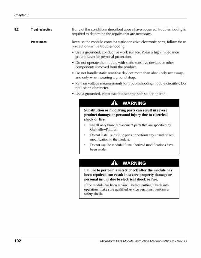
Chapter 8
102 Micro-Ion® Plus Module Instruction Manual - 392002 - Rev. G
8.2 Troubleshooting If any of the conditions described above have occurred, troubleshooting is required to determine the repairs that are necessary.
Precautions Because the module contains static-sensitive electronic parts, follow these precautions while troubleshooting:
• Use a grounded, conductive work surface. Wear a high impedance ground strap for personal protection.
• Do not operate the module with static sensitive devices or other components removed from the product.
• Do not handle static sensitive devices more than absolutely necessary, and only when wearing a ground strap.
• Rely on voltage measurements for troubleshooting module circuitry. Do not use an ohmmeter.
• Use a grounded, electrostatic discharge safe soldering iron.
WARNINGSubstitution or modifying parts can result in severe product damage or personal injury due to electrical shock or fire.
• Install only those replacement parts that are specified by Granville−Phillips.
• Do not install substitute parts or perform any unauthorized modification to the module.
• Do not use the module if unauthorized modifications have been made.
WARNINGFailure to perform a safety check after the module has been repaired can result in severe property damage or personal injury due to electrical shock or fire.
If the module has been repaired, before putting it back into operation, make sure qualified service personnel perform a safety check.
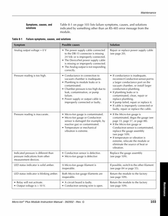
Maintenance
Micro-Ion® Plus Module Instruction Manual - 392002 - Rev. G 103
DeviceNet OperationRS-485 Operation
Optional DisplayM
aintenance
Symptoms, causes, and solutions
Table 8-1 on page 103 lists failure symptoms, causes, and solutions indicated by something other than an RS-485 error message from the module.
Table 8-1 Failure symptoms, causes, and solutions
Symptom Possible causes Solution
Analog output voltage = 0 V • The power supply cable connected to the DB-15 connector is missing 24 Vdc or is improperly connected.
• The DeviceNet power supply cable is missing or improperly connected.
• The Analog output is not responding correctly.
Repair or replace power supply cable (see page 20).
Pressure reading is too high. • Conductance in connection to vacuum chamber is inadequate.
• Plumbing to module leaks or is contaminated.
• Chamber pressure is too high due to leak, contamination, or pump failure.
• Power supply or output cable is improperly connected or faulty.
• If conductance is inadequate, reconnect Conductron sensor port to a larger conductance port on the vacuum chamber, or install larger conductance plumbing.
• If plumbing leaks or is contaminated, clean, repair or replace plumbing.
• If pump failed, repair or replace it.• If cable is improperly connected or
faulty, repair or replace the cable.
Pressure reading is inaccurate. • Micro-Ion gauge is contaminated.• Micro-Ion gauge or Conductron
sensor is damaged (for example, by reactive gas) or contaminated.
• Temperature or mechanical vibration is extreme.
• If the Micro-Ion gauge is contaminated, degas the gauge (see page 33, page 57, or page 88).
• If the Micro-Ion gauge or Conductron sensor is contaminated, replace the gauge assembly (see page 109).
• If temperature or vibration is extreme, relocate the module or eliminate the source of heat or vibration.
Indicated pressure is different than pressure indications from other measurement devices.
• Conductron sensor is defective.• Micro-Ion gauge is defective
Replace the gauge assembly (see page 109).
LED status indicator is solid amber. A Micro-Ion gauge filament is inoperable.
If possible, switch to the other filament (see page 84 or page 55).
LED status indicator is blinking amber. Both Micro-Ion gauge filaments are inoperable.
Return the module to the factory (see page 109).
• Relay will not activate.• Output voltage is > 10 V.
• A circuit board is faulty.• Conductron sensing wire is open.
Return the module to the factory (see page 109).
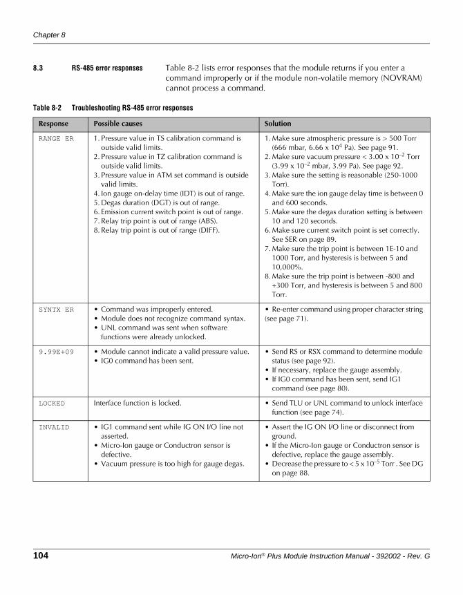
Chapter 8
104 Micro-Ion® Plus Module Instruction Manual - 392002 - Rev. G
8.3 RS-485 error responses Table 8-2 lists error responses that the module returns if you enter a command improperly or if the module non-volatile memory (NOVRAM) cannot process a command.
Table 8-2 Troubleshooting RS-485 error responses
Response Possible causes Solution
RANGE ER 1. Pressure value in TS calibration command is outside valid limits.
2. Pressure value in TZ calibration command is outside valid limits.
3. Pressure value in ATM set command is outside valid limits.
4. Ion gauge on-delay time (IDT) is out of range.5. Degas duration (DGT) is out of range.6. Emission current switch point is out of range.7. Relay trip point is out of range (ABS).8. Relay trip point is out of range (DIFF).
1. Make sure atmospheric pressure is > 500 Torr (666 mbar, 6.66 x 10⁴ Pa). See page 91.
2. Make sure vacuum pressure < 3.00 x 10⁻² Torr (3.99 x 10⁻² mbar, 3.99 Pa). See page 92.
3. Make sure the setting is reasonable (250-1000 Torr).
4. Make sure the ion gauge delay time is between 0 and 600 seconds.
5. Make sure the degas duration setting is between 10 and 120 seconds.
6. Make sure current switch point is set correctly. See SER on page 89.
7. Make sure the trip point is between 1E-10 and 1000 Torr, and hysteresis is between 5 and 10,000%.
8. Make sure the trip point is between -800 and +300 Torr, and hysteresis is between 5 and 800 Torr.
SYNTX ER • Command was improperly entered.• Module does not recognize command syntax.• UNL command was sent when software
functions were already unlocked.
• Re-enter command using proper character string (see page 71).
9.99E+09 • Module cannot indicate a valid pressure value.• IG0 command has been sent.
• Send RS or RSX command to determine module status (see page 92).
• If necessary, replace the gauge assembly.• If IG0 command has been sent, send IG1
command (see page 80).
LOCKED Interface function is locked. • Send TLU or UNL command to unlock interface function (see page 74).
INVALID • IG1 command sent while IG ON I/O line not asserted.
• Micro-Ion gauge or Conductron sensor is defective.
• Vacuum pressure is too high for gauge degas.
• Assert the IG ON I/O line or disconnect from ground.
• If the Micro-Ion gauge or Conductron sensor is defective, replace the gauge assembly.
• Decrease the pressure to < 5 x 10⁻⁵ Torr . See DG on page 88.
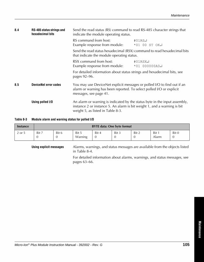
Maintenance
Micro-Ion® Plus Module Instruction Manual - 392002 - Rev. G 105
DeviceNet OperationRS-485 Operation
Optional DisplayM
aintenance
8.4 RS-485 status strings and hexadecimal bits
Send the read status (RS) command to read RS-485 character strings that indicate the module operating status.
RS command from host: #01RS↵Example response from module: *01 00 ST OK↵
Send the read status hexadecimal (RSX) command to read hexadecimal bits that indicate the module operating status.
RSX command from host: #01RSX↵Example response from module: *01 000000A0↵
For detailed information about status strings and hexadecimal bits, see pages 92–96.
8.5 DeviceNet error codes You may use DeviceNet explicit messages or polled I/O to find out if an alarm or warning has been reported. To select polled I/O or explicit messages, see page 41.
Using polled I/O An alarm or warning is indicated by the status byte in the input assembly, instance 2 or instance 5. An alarm is bit weight 1, and a warning is bit weight 5, as listed in Table 8-3.
Using explicit messages Alarms, warnings, and status messages are available from the objects listed in Table 8-4.
For detailed information about alarms, warnings, and status messages, see pages 63–66.
Table 8-3 Module alarm and warning status for polled I/O
Instance BYTE data: One byte format
2 or 5 Bit 70
Bit 60
Bit 5Warning
Bit 40
Bit 30
Bit 20
Bit 1Alarm
Bit 00
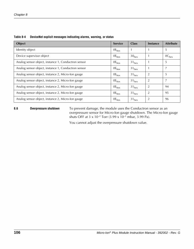
Chapter 8
106 Micro-Ion® Plus Module Instruction Manual - 392002 - Rev. G
8.6 Overpressure shutdown To prevent damage, the module uses the Conductron sensor as an overpressure sensor for Micro-Ion gauge shutdown. The Micro-Ion gauge shuts OFF at 3 x 10⁻² Torr (3.99 x 10⁻² mbar, 3.99 Pa).
You cannot adjust the overpressure shutdown value.
Table 8-4 DeviceNet explicit messages indicating alarms, warning, or status
Object Service Class Instance Attribute
Identity object 0Ehex 1 1 5
Device supervisor object 0Ehex 30hex 1 0Chex
Analog sensor object, instance 1, Conductron sensor 0Ehex 31hex 1 5
Analog sensor object, instance 1, Conductron sensor 0Ehex 31hex 1 7
Analog sensor object, instance 2, Micro-Ion gauge 0Ehex 31hex 2 5
Analog sensor object, instance 2, Micro-Ion gauge 0Ehex 31hex 2 7
Analog sensor object, instance 2, Micro-Ion gauge 0Ehex 31hex 2 94
Analog sensor object, instance 2, Micro-Ion gauge 0Ehex 31hex 2 95
Analog sensor object, instance 2, Micro-Ion gauge 0Ehex 31hex 2 96
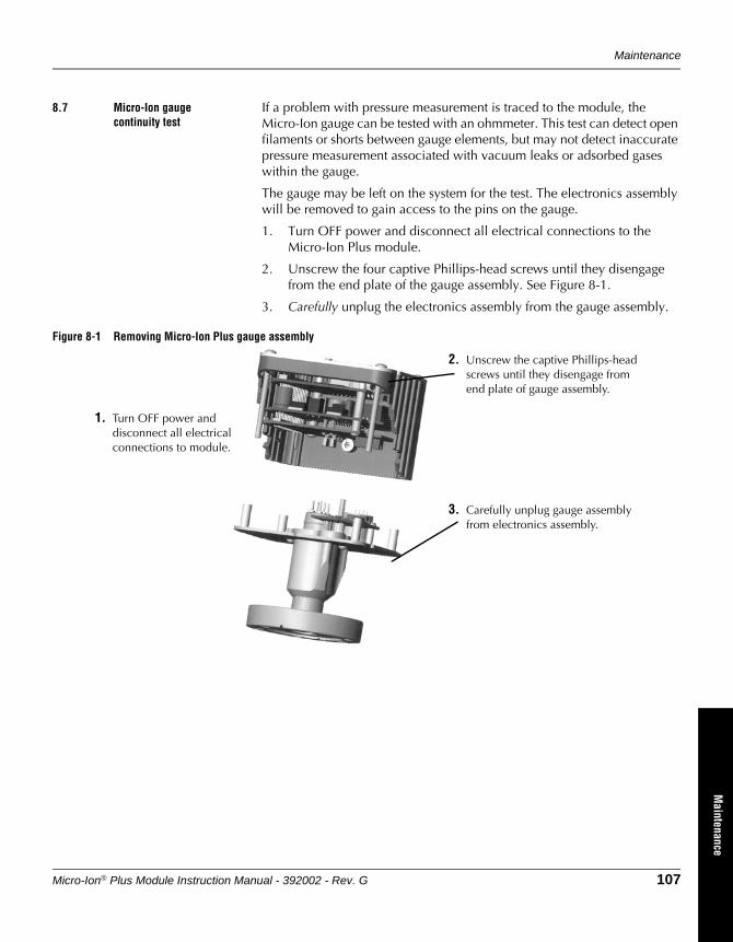
Maintenance
Micro-Ion® Plus Module Instruction Manual - 392002 - Rev. G 107
DeviceNet OperationRS-485 Operation
Optional DisplayM
aintenance
8.7 Micro-Ion gauge continuity test
If a problem with pressure measurement is traced to the module, the Micro-Ion gauge can be tested with an ohmmeter. This test can detect open filaments or shorts between gauge elements, but may not detect inaccurate pressure measurement associated with vacuum leaks or adsorbed gases within the gauge.
The gauge may be left on the system for the test. The electronics assembly will be removed to gain access to the pins on the gauge.
1. Turn OFF power and disconnect all electrical connections to the Micro-Ion Plus module.
2. Unscrew the four captive Phillips-head screws until they disengage from the end plate of the gauge assembly. See Figure 8-1.
3. Carefully unplug the electronics assembly from the gauge assembly.
Figure 8-1 Removing Micro-Ion Plus gauge assembly
1. Turn OFF power and disconnect all electrical connections to module.
2. Unscrew the captive Phillips-head screws until they disengage from end plate of gauge assembly.
3. Carefully unplug gauge assembly from electronics assembly.
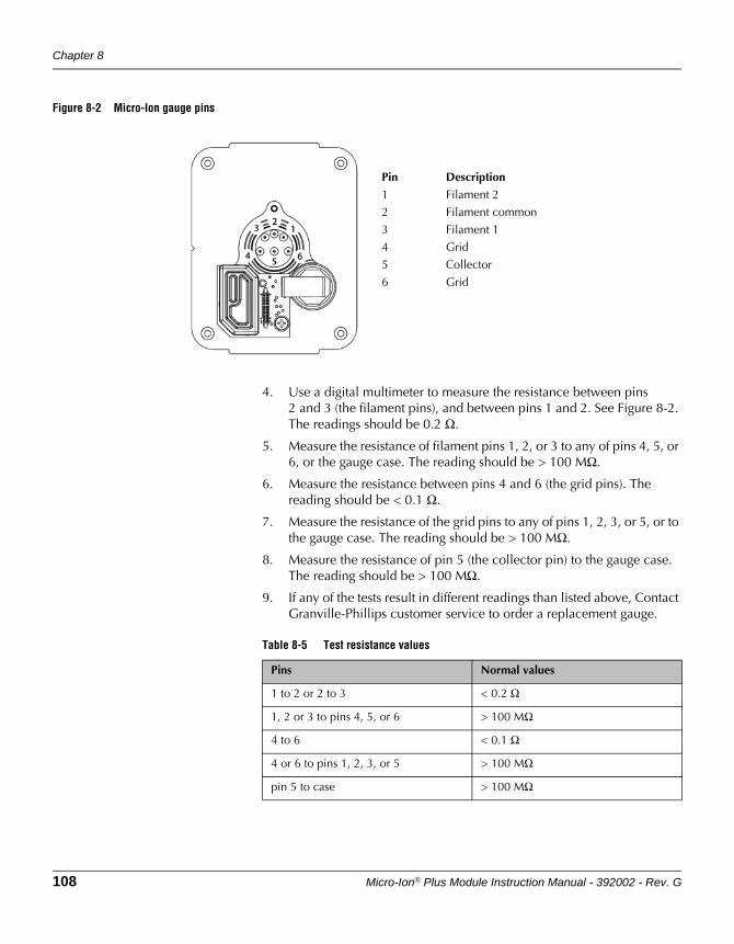
Chapter 8
108 Micro-Ion® Plus Module Instruction Manual - 392002 - Rev. G
Figure 8-2 Micro-Ion gauge pins
4. Use a digital multimeter to measure the resistance between pins 2 and 3 (the filament pins), and between pins 1 and 2. See Figure 8-2. The readings should be 0.2 Ω.
5. Measure the resistance of filament pins 1, 2, or 3 to any of pins 4, 5, or 6, or the gauge case. The reading should be > 100 MΩ.
6. Measure the resistance between pins 4 and 6 (the grid pins). The reading should be < 0.1 Ω.
7. Measure the resistance of the grid pins to any of pins 1, 2, 3, or 5, or to the gauge case. The reading should be > 100 MΩ.
8. Measure the resistance of pin 5 (the collector pin) to the gauge case. The reading should be > 100 MΩ.
9. If any of the tests result in different readings than listed above, Contact Granville-Phillips customer service to order a replacement gauge.
Pin Description
1 Filament 2
2 Filament common
3 Filament 1
4 Grid
5 Collector
6 Grid
Table 8-5 Test resistance values
Pins Normal values
1 to 2 or 2 to 3 < 0.2 Ω
1, 2 or 3 to pins 4, 5, or 6 > 100 MΩ
4 to 6 < 0.1 Ω
4 or 6 to pins 1, 2, 3, or 5 > 100 MΩ
pin 5 to case > 100 MΩ
Maintenance
Micro-Ion® Plus Module Instruction Manual - 392002 - Rev. G 109
DeviceNet OperationRS-485 Operation
Optional DisplayM
aintenance
8.8 Replacing the gauge assembly
Do not plug in or unplug any connectors with power applied to the module. Disconnect power from the module before replacing the gauge assembly.
1. Turn OFF power and disconnect all electrical connections to the Micro-Ion Plus module.
2. Disconnect the module from the vacuum chamber.
3. Unscrew the four captive Phillips-head screws until they disengage from the end plate of the gauge assembly. See Figure 8-1.
4. Carefully unplug the electronics assembly from the gauge assembly.
5. Insert the new gauge assembly into the electronics assembly by gently inserting the gauge pins into the socket on the circuit board. Examine the gauge pin arrangement to make sure the replacement gauge assembly and electronics assembly are aligned.
6. Tighten the four Phillips-head screws.
7. Install the module on the vacuum chamber.
8. Calibrate the module at atmospheric pressure (see page 34, page 91, or page 60).
8.9 Returning a damaged module
If the product requires service, contact the MKS, Granville-Phillips Division Customer Service Department at +1-800-227-8766 or +1-303-652-4691 for troubleshooting help over the phone.
If the product must be returned to the factory for service, request a Return Material Authorization (RMA) from Granville-Phillips. Do not return products without first obtaining an RMA. In some cases a hazardous materials document may be required. The MKS/Granville-Phillips Customer Service Representative will advise you if the hazardous materials document is required.
When returning a products to Granville-Phillips, be sure to package the products to prevent shipping damage. Circuit boards and modules separated from the gauge assembly must be handled using proper anti-static protection methods and must be packaged in anti-static packaging. Granville-Phillips will supply return packaging materials at no charge upon request. Shipping damage on returned products as a result of inadequate packaging is the Buyer's responsibility.
For Customer Service or Technical Support 24 hours per day, 7 days per week, every day of the year including holidays:
Phone: +1-800-227-8766 or +1-303-652-4691Email: [email protected]
MKS, Granville-Phillips Division6450 Dry Creek ParkwayLongmont, CO 80503 USAPhone: 1-303-652-4691 or 1-800-776-6543 / FAX: 1-303-652-2844

Chapter 8
110 Micro-Ion® Plus Module Instruction Manual - 392002 - Rev. G
Micro-Ion® Plus Module Instruction Manual - 392002 - Rev. G 111
Appendix A Specifications& Compliance
Pressure Measurement Specifications
Atmospheric value is based on calibration at time of use.
Measurements will change with different gases and mixtures.
Pressure range Torr 1 x 10⁻⁹ to atmospherembar 1.33 x 10⁻⁹ to atmospherePascal 1.33 x 10⁻⁷ to atmosphere
Accuracy for N2 or Air Accuracy (the difference between the gauge reading and a calibrated reference standard) is determined statistically and includes the combined performance of the gauge, sensors, and electronics.
1 x 10⁻⁸ Torr to 100 mTorr ±15% of reading1.33 x 10–8 to 0.133 mbar ±15% of reading1.33 x 10–6 to 13.3 Pa ±15% of reading
100 mTorr to 150 Torr ±10% of reading0.133 to 200 mbar ±10% of reading13.3 to 2.00 x 10⁴ Pa ±10% of reading
Repeatability Repeatability refers to the ability of the same module to read the same pressure at different times.
1 x 10⁻⁸ Torr to 100 mTorr ±5% of reading1.33 x 10–8 to 0.133 mbar ±5% of reading1.33 x 10–6 to 13.3 Pa ±5% of reading
100 mTorr to 150 Torr ±2.5% of reading0.133 to 200 mbar ±2.5% of reading13.3 to 2.00 x 10⁴ Pa ±2.5% of reading
X-ray limit X-ray limit is the absolute lowest indication from the gauge. It is not possible to make repeatable measurements near the x-ray limit.
Torr < 3 x 10⁻¹⁰
mbar < 4 x 10⁻¹⁰
Pascal < 4 x 10⁻⁸
Response time < 25 msec
Temperature Specifications
Operating temperature 10 to 40 ºC (50 to 104 ºF), non-condensing
Storage temperature –40 to +70 ºC (–40 to +158 ºF)
Bakeout temperature 105 ºC (221 ºF) maximum with electronics removed
Appendix A
112 Micro-Ion® Plus Module Instruction Manual - 392002 - Rev. G
Outputs and Indicators
Available output options The module has a DeviceNet interface, an RS-485 interface, and one analog output. The module may also have an optional display.
Analog output • Logarithmic, 0.5 to 7.0 Vdc, 0.5 volt per decade
• Analog ground is galvanically isolated from the DeviceNet ground and the chassis ground up to 1500 V
Digital DeviceNet output
Messaging Polled I/O and explicit
Communications format BOOL, BYTE, STRUCT, SSTRING, REAL, INT, UINT, USINT, EPATH, and WORD data
Data rates 125, 250, or 500 kbaud, switch selectable
Address 0–63, selected by using data rate switch
I/O slave messaging Polling, COS, cyclic
NET status LED indicator The NET status LED lights up to indicate if the DeviceNet network has power and is functioning properly.
MOD status LED indicator The MOD status LED lights up to indicate if the module has power or is functioning properly.
Digital RS-485 output
Interface RS-485 two-wire, half-duplex
Communications format ASCII format, eight data bits, no parity, one stop bit
Baud rates 1200, 2400, 4800, 9600, 19200 (default), or 38400 baud
Address 0 to 63, selected by using address switch and RS-485 command
LED status indicator The status indicator illuminates to indicate the Micro-Ion sensor status:
LED is solid green - indicates power is ON and the Micro-Ion sensor is OFF
LED blinks green - indicates that the Micro-Ion sensor is ON
LED is solid amber - indicates the Micro-Ion sensor is ON but one filament is inoperable
LED blinks amber - indicates the Micro-Ion sensor is ON but both filaments are inoperable
Specifications & Compliance
Micro-Ion® Plus Module Instruction Manual - 392002 - Rev. G 113
Optional Display
Backlit, 72-dot by 48-dot matrix can indicate vacuum pressure and error conditions.
Pressure range 0.1 x 10⁻¹⁰ to atmosphere
Display resolution The resolution of the numeric display changes over the operating range of the module.
Pressure values in the 10–10 range (such as 6 x 10⁻¹⁰) will appear as “0.6–9”.
Pressure units Display indicates Torr “(TORR”), mbar (“MBAR”), or pascal (“PA”) as the unit of pressure.
The “A” to the right of the pressure unit indicates vacuum (absolute) pressure.
X.X±Y display format includes two significant digits, a 1-digit exponent, and a ± sign for the exponent.
“A” to the right of the pressure unit indicates vacuum (absolute) pressure.
Error conditions If an error condition exists, the display indicates the condition.
If more than one error condition exists, the display indicates the first condition, then reverts to indicating the pressure unit, then indicates the second condition, etc. The display continues scrolling through the error indications until all conditions have been diagnosed and eliminated.
Optional Trip Point Relays
Relay type Two single-pole double-throw (normally open/normally closed) or three single-pole single-throw (normally open) relays.
Relay contact ratings Relay contacts are silver alloy-gold clad, rated for 1 A at 30 Vdc. The relays can handle resistive loads.
Maximum 1 A at 30 Vdc, resistive load
Minimum 5 mA at 5 Vdc, resistive load
Minimum hysteresis 5% vacuum pressure
Range 1.0 x 10⁻⁹ to 1000 Torr1.33 x 10–9 to 1333 mbar1.33 x 10–7 to 1.33 x 10⁵ Pa
Default activation pressure Default activation pressures are out of range and require configuration.
Appendix A
114 Micro-Ion® Plus Module Instruction Manual - 392002 - Rev. G
Micro-Ion Sensor
Emission current 0.02 mA or 4 mA, automatically set
Use RS-485 commands to set switch point for high and low emission currents.
Default control settings
Gauge on 2 x 10⁻² Torr with decreasing pressure2.66 x 10–2 mbar with decreasing pressure2.66 Pa with decreasing pressure
Gauge off 3 x 10⁻² Torr with increasing pressure3.99 x 10–2 mbar with increasing pressure3.99 Pa with increasing pressure
Switch to high emission 5 x 10⁻⁶ Torr with decreasing pressure6.66 x 10–6 mbar with decreasing pressure6.66 x 10–4 Pa with decreasing pressure
Switch to low emission 1 x 10⁻⁵ Torr with increasing pressure1.33 x 10–5 mbar with increasing pressure1.33 x 10–3 Pa with increasing pressure
Gauge degas Electron bombardment; 3 W for default time of 1 minute per filament.
Degas time is programmable from 10 to 120 seconds using the RS-485 interface.
Filaments Solid tungsten or yttria-coated iridium
Filament operation mode
Alternating mode Module alternates between filaments with each activation of the gauge.
Automatic mode Filament 1 is used until it becomes inoperable, then the module automatically switches to filament 2.
Manual mode Filament 1 is used until it becomes inoperable, then manual intervention is required to activate filament 2.
Both mode Both filament 1 and filament 2 are ON until one of the filaments becomes inoperable, then the operable filament continues to function.
NOTES: During low-emission operation in the Both mode, (the default for yttria-coated iridium filaments) both filaments are operating (ON). During high-emission operation of yttria-coated filaments, the default is "alternating mode; during high-emission operation with Tungsten filaments, the default mode is "manual" mode.
Conductron Heat-loss Sensor
Sensing wires Gold-plated tungsten
Specifications & Compliance
Micro-Ion® Plus Module Instruction Manual - 392002 - Rev. G 115
Electrical Connectors
I/O connector 15-pin subminiature D male connector has terminals for module power supply, analog output, RS-485 output, relays, Micro-Ion gauge ON/OFF, and Micro-Ion gauge degas.
Cable types For cable that connects to the 15-pin I/O connector, install shielded cable with aluminum jacket and a tinned copper braid with a minimum of 65% coverage.
On the module end of the cable, install a metal housing, so the shield is continuous from the cable to the gauge housing. Do not ground the shield at the system end.
Module power supply Power supply requirement is 24 Vdc +10% to –15%, 1 A, 22 W nominal.
Maximum inrush current is 2 amps, 48 W, for 0.5 seconds.
Power supply must supply at least 2 amps (48 W) of current for at least 0.5 seconds during Micro-Ion sensor start up. The Micro-Ion sensor will not activate and an emission error will occur if insufficient power is supplied during Micro-Ion sensor activation.
Power inputs are reverse-biased protected.
DeviceNet micro connector DeviceNet 5-pin micro connector has terminals for a standard micro 5-pin female cable connection.
Cable types Install raw cable that has a braided shield over the aluminum foil-shielded signal and power wires.
On the module end of the cable, install a metal housing, so the shield is continuous from the cable to the gauge housing. Do not ground the shield at the receiver or output device.
DeviceNet power supply The module will use terminals 2 (Vdc return) and 3 (24 Vdc) on the 5-pin DeviceNet micro connector for the network power supply.
The DeviceNet interface requires 24 Vdc (11 to 26.4) at 0.2 A maximum.
Maximum inrush current is 0.25 A.
Power inputs are reverse-bias protected.
Compliance
Compliance with CE Mark requires metal connector housings and cable with a braided shield. The braided shield must be connected only to the outer shell of the 15-pin subminiature D connector or 5-pin DeviceNet micro connector on the module, not to the receiver or output device.
EMC EN61326-1
Product Safety EN61010-1
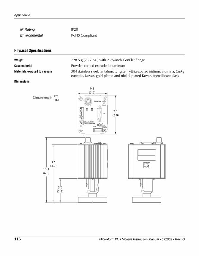
Appendix A
116 Micro-Ion® Plus Module Instruction Manual - 392002 - Rev. G
IP Rating IP20
Environmental RoHS Compliant
Physical Specifications
Weight 728.5 g (25.7 oz.) with 2.75-inch ConFlat flange
Case material Powder-coated extruded aluminum
Materials exposed to vacuum 304 stainless steel, tantalum, tungsten, yttria-coated iridium, alumina, CuAg eutectic, Kovar, gold-plated and nickel-plated Kovar, borosilicate glass
Dimensions
7.1(2.8)
12(4.7)
Dimensions in cm(in.)
5.6(2.2)
9.1(3.6)
15.1(6.0)
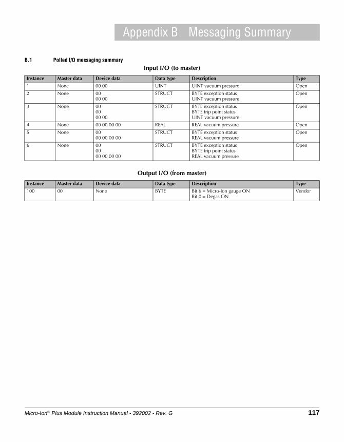
Micro-Ion® Plus Module Instruction Manual - 392002 - Rev. G 117
Appendix B Messaging Summary
B.1 Polled I/O messaging summaryInput I/O (to master)
Instance Master data Device data Data type Description Type
1 None 00 00 UINT UINT vacuum pressure Open
2 None 0000 00
STRUCT BYTE exception statusUINT vacuum pressure
Open
3 None 000000 00
STRUCT BYTE exception statusBYTE trip point statusUINT vacuum pressure
Open
4 None 00 00 00 00 REAL REAL vacuum pressure Open
5 None 0000 00 00 00
STRUCT BYTE exception statusREAL vacuum pressure
Open
6 None 000000 00 00 00
STRUCT BYTE exception statusBYTE trip point statusREAL vacuum pressure
Open
Output I/O (from master)
Instance Master data Device data Data type Description Type
100 00 None BYTE Bit 6 = Micro-Ion gauge ONBit 0 = Degas ON
Vendor
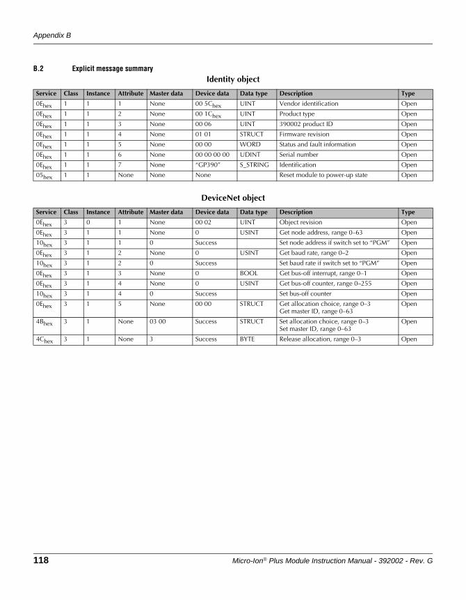
Appendix B
118 Micro-Ion® Plus Module Instruction Manual - 392002 - Rev. G
B.2 Explicit message summaryIdentity object
Service Class Instance Attribute Master data Device data Data type Description Type
0Ehex 1 1 1 None 00 5Chex UINT Vendor identification Open
0Ehex 1 1 2 None 00 1Chex UINT Product type Open
0Ehex 1 1 3 None 00 06 UINT 390002 product ID Open
0Ehex 1 1 4 None 01 01 STRUCT Firmware revision Open
0Ehex 1 1 5 None 00 00 WORD Status and fault information Open
0Ehex 1 1 6 None 00 00 00 00 UDINT Serial number Open
0Ehex 1 1 7 None “GP390” S_STRING Identification Open
05hex 1 1 None None None Reset module to power-up state Open
DeviceNet object
Service Class Instance Attribute Master data Device data Data type Description Type
0Ehex 3 0 1 None 00 02 UINT Object revision Open
0Ehex 3 1 1 None 0 USINT Get node address, range 0–63 Open
10hex 3 1 1 0 Success Set node address if switch set to “PGM” Open
0Ehex 3 1 2 None 0 USINT Get baud rate, range 0–2 Open
10hex 3 1 2 0 Success Set baud rate if switch set to “PGM” Open
0Ehex 3 1 3 None 0 BOOL Get bus-off interrupt, range 0–1 Open
0Ehex 3 1 4 None 0 USINT Get bus-off counter, range 0–255 Open
10hex 3 1 4 0 Success Set bus-off counter Open
0Ehex 3 1 5 None 00 00 STRUCT Get allocation choice, range 0–3Get master ID, range 0–63
Open
4Bhex 3 1 None 03 00 Success STRUCT Set allocation choice, range 0–3Set master ID, range 0–63
Open
4Chex 3 1 None 3 Success BYTE Release allocation, range 0–3 Open
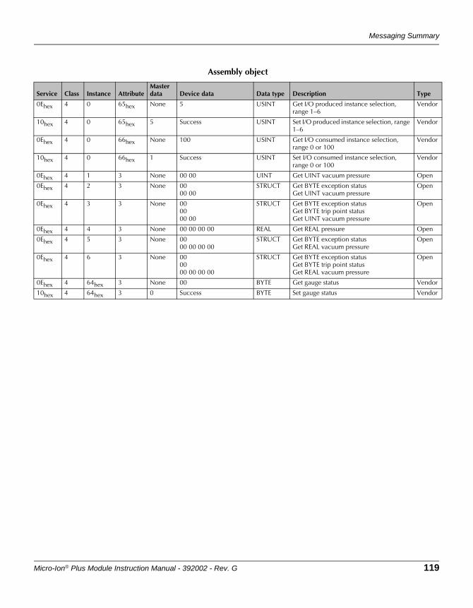
Messaging Summary
Micro-Ion® Plus Module Instruction Manual - 392002 - Rev. G 119
Assembly object
Service Class Instance AttributeMaster data Device data Data type Description Type
0Ehex 4 0 65hex None 5 USINT Get I/O produced instance selection, range 1–6
Vendor
10hex 4 0 65hex 5 Success USINT Set I/O produced instance selection, range 1–6
Vendor
0Ehex 4 0 66hex None 100 USINT Get I/O consumed instance selection, range 0 or 100
Vendor
10hex 4 0 66hex 1 Success USINT Set I/O consumed instance selection, range 0 or 100
Vendor
0Ehex 4 1 3 None 00 00 UINT Get UINT vacuum pressure Open
0Ehex 4 2 3 None 0000 00
STRUCT Get BYTE exception statusGet UINT vacuum pressure
Open
0Ehex 4 3 3 None 000000 00
STRUCT Get BYTE exception statusGet BYTE trip point statusGet UINT vacuum pressure
Open
0Ehex 4 4 3 None 00 00 00 00 REAL Get REAL pressure Open
0Ehex 4 5 3 None 0000 00 00 00
STRUCT Get BYTE exception statusGet REAL vacuum pressure
Open
0Ehex 4 6 3 None 000000 00 00 00
STRUCT Get BYTE exception statusGet BYTE trip point statusGet REAL vacuum pressure
Open
0Ehex 4 64hex 3 None 00 BYTE Get gauge status Vendor
10hex 4 64hex 3 0 Success BYTE Set gauge status Vendor
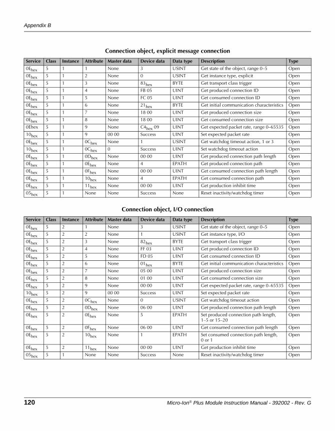
Appendix B
120 Micro-Ion® Plus Module Instruction Manual - 392002 - Rev. G
Connection object, explicit message connection
Service Class Instance Attribute Master data Device data Data type Description Type
0Ehex 5 1 1 None 3 USINT Get state of the object, range 0–5 Open
0Ehex 5 1 2 None 0 USINT Get instance type, explicit Open
0Ehex 5 1 3 None 83hex BYTE Get transport class trigger Open
0Ehex 5 1 4 None FB 05 UINT Get produced connection ID Open
0Ehex 5 1 5 None FC 05 UINT Get consumed connection ID Open
0Ehex 5 1 6 None 21hex BYTE Get initial communication characteristics Open
0Ehex 5 1 7 None 18 00 UINT Get produced connection size Open
0Ehex 5 1 8 None 18 00 UINT Get consumed connection size Open
0Ehex 5 1 9 None C4hex 09 UINT Get expected packet rate, range 0–65535 Open
10hex 5 1 9 00 00 Success UINT Set expected packet rate Open
0Ehex 5 1 0Chex None 1 USINT Get watchdog timeout action, 1 or 3 Open
10hex 5 1 0Chex 0 Success UINT Set watchdog timeout action Open
0Ehex 5 1 0Dhex None 00 00 UINT Get produced connection path length Open
0Ehex 5 1 0Ehex None 4 EPATH Get produced connection path Open
0Ehex 5 1 0Fhex None 00 00 UINT Get consumed connection path length Open
0Ehex 5 1 10hex None 4 EPATH Get consumed connection path Open
0Ehex 5 1 11hex None 00 00 UINT Get production inhibit time Open
05hex 5 1 None None Success None Reset inactivity/watchdog timer Open
Connection object, I/O connection
Service Class Instance Attribute Master data Device data Data type Description Type
0Ehex 5 2 1 None 3 USINT Get state of the object, range 0–5 Open
0Ehex 5 2 2 None 1 USINT Get instance type, I/O Open
0Ehex 5 2 3 None 82hex BYTE Get transport class trigger Open
0Ehex 5 2 4 None FF 03 UINT Get produced connection ID Open
0Ehex 5 2 5 None FD 05 UINT Get consumed connection ID Open
0Ehex 5 2 6 None 01hex BYTE Get initial communication characteristics Open
0Ehex 5 2 7 None 05 00 UINT Get produced connection size Open
0Ehex 5 2 8 None 01 00 UINT Get consumed connection size Open
0Ehex 5 2 9 None 00 00 UINT Get expected packet rate, range 0–65535 Open
10hex 5 2 9 00 00 Success UINT Set expected packet rate Open
0Ehex 5 2 0Chex None 0 USINT Get watchdog timeout action Open
0Ehex 5 2 0Dhex None 06 00 UINT Get produced connection path length Open
0Ehex 5 2 0Ehex None 5 EPATH Set produced connection path length,1–5 or 15–20
Open
0Ehex 5 2 0Fhex None 06 00 UINT Get consumed connection path length Open
0Ehex 5 2 10hex None 1 EPATH Set consumed connection path length,0 or 1
Open
0Ehex 5 2 11hex None 00 00 UINT Get production inhibit time Open
05hex 5 1 None None Success None Reset inactivity/watchdog timer Open
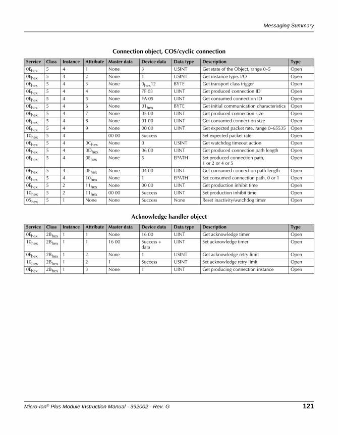
Messaging Summary
Micro-Ion® Plus Module Instruction Manual - 392002 - Rev. G 121
Connection object, COS/cyclic connection
Service Class Instance Attribute Master data Device data Data type Description Type
0Ehex 5 4 1 None 3 USINT Get state of the Object, range 0–5 Open
0Ehex 5 4 2 None 1 USINT Get instance type, I/O Open
0Ehex 5 4 3 None 0hex12 BYTE Get transport class trigger Open
0Ehex 5 4 4 None 7F 03 UINT Get produced connection ID Open
0Ehex 5 4 5 None FA 05 UINT Get consumed connection ID Open
0Ehex 5 4 6 None 01hex BYTE Get initial communication characteristics Open
0Ehex 5 4 7 None 05 00 UINT Get produced connection size Open
0Ehex 5 4 8 None 01 00 UINT Get consumed connection size Open
0Ehex 5 4 9 None 00 00 UINT Get expected packet rate, range 0–65535 Open
10hex 5 4 00 00 Success Set expected packet rate Open
0Ehex 5 4 0Chex None 0 USINT Get watchdog timeout action Open
0Ehex 5 4 0Dhex None 06 00 UINT Get produced connection path length Open
0Ehex 5 4 0Ehex None 5 EPATH Set produced connection path,1 or 2 or 4 or 5
Open
0Ehex 5 4 0Fhex None 04 00 UINT Get consumed connection path length Open
0Ehex 5 4 10hex None 1 EPATH Set consumed connection path, 0 or 1 Open
0Ehex 5 2 11hex None 00 00 UINT Get production inhibit time Open
10hex 5 2 11hex 00 00 Success UINT Set production inhibit time Open
05hex 5 1 None None Success None Reset inactivity/watchdog timer Open
Acknowledge handler object
Service Class Instance Attribute Master data Device data Data type Description Type
0Ehex 2Bhex 1 1 None 16 00 UINT Get acknowledge timer Open
10hex 2Bhex 1 1 16 00 Success + data
UINT Set acknowledge timer Open
0Ehex 2Bhex 1 2 None 1 USINT Get acknowledge retry limit Open
10hex 2Bhex 1 2 1 Success USINT Set acknowledge retry limit Open
0Ehex 2Bhex 1 3 None 1 UINT Get producing connection instance Open
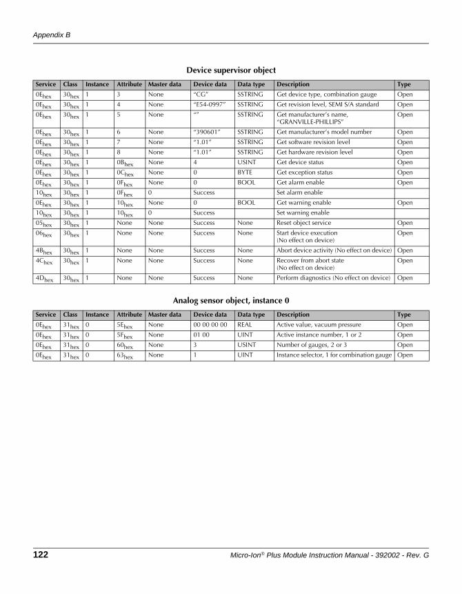
Appendix B
122 Micro-Ion® Plus Module Instruction Manual - 392002 - Rev. G
Device supervisor object
Service Class Instance Attribute Master data Device data Data type Description Type
0Ehex 30hex 1 3 None “CG” SSTRING Get device type, combination gauge Open
0Ehex 30hex 1 4 None “E54-0997” SSTRING Get revision level, SEMI S/A standard Open
0Ehex 30hex 1 5 None “” SSTRING Get manufacturer’s name, “GRANVILLE-PHILLIPS”
Open
0Ehex 30hex 1 6 None “390601” SSTRING Get manufacturer’s model number Open
0Ehex 30hex 1 7 None “1.01” SSTRING Get software revision level Open
0Ehex 30hex 1 8 None “1.01” SSTRING Get hardware revision level Open
0Ehex 30hex 1 0Bhex None 4 USINT Get device status Open
0Ehex 30hex 1 0Chex None 0 BYTE Get exception status Open
0Ehex 30hex 1 0Fhex None 0 BOOL Get alarm enable Open
10hex 30hex 1 0Fhex 0 Success Set alarm enable
0Ehex 30hex 1 10hex None 0 BOOL Get warning enable Open
10hex 30hex 1 10hex 0 Success Set warning enable
05hex 30hex 1 None None Success None Reset object service Open
06hex 30hex 1 None None Success None Start device execution(No effect on device)
Open
4Bhex 30hex 1 None None Success None Abort device activity (No effect on device) Open
4Chex 30hex 1 None None Success None Recover from abort state(No effect on device)
Open
4Dhex 30hex 1 None None Success None Perform diagnostics (No effect on device) Open
Analog sensor object, instance 0
Service Class Instance Attribute Master data Device data Data type Description Type
0Ehex 31hex 0 5Ehex None 00 00 00 00 REAL Active value, vacuum pressure Open
0Ehex 31hex 0 5Fhex None 01 00 UINT Active instance number, 1 or 2 Open
0Ehex 31hex 0 60hex None 3 USINT Number of gauges, 2 or 3 Open
0Ehex 31hex 0 63hex None 1 UINT Instance selector, 1 for combination gauge Open
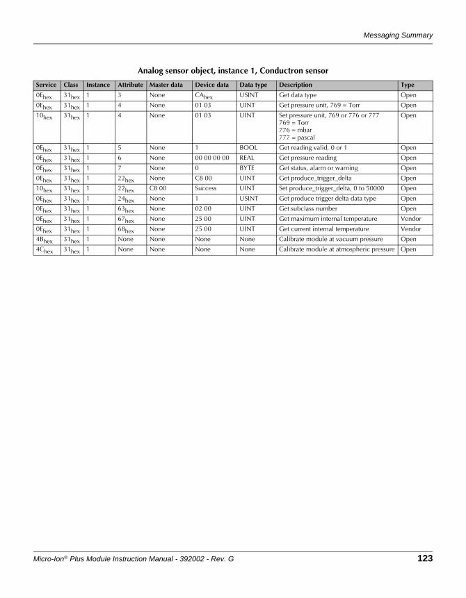
Messaging Summary
Micro-Ion® Plus Module Instruction Manual - 392002 - Rev. G 123
Analog sensor object, instance 1, Conductron sensor
Service Class Instance Attribute Master data Device data Data type Description Type
0Ehex 31hex 1 3 None CAhex USINT Get data type Open
0Ehex 31hex 1 4 None 01 03 UINT Get pressure unit, 769 = Torr Open
10hex 31hex 1 4 None 01 03 UINT Set pressure unit, 769 or 776 or 777769 = Torr776 = mbar777 = pascal
Open
0Ehex 31hex 1 5 None 1 BOOL Get reading valid, 0 or 1 Open
0Ehex 31hex 1 6 None 00 00 00 00 REAL Get pressure reading Open
0Ehex 31hex 1 7 None 0 BYTE Get status, alarm or warning Open
0Ehex 31hex 1 22hex None C8 00 UINT Get produce_trigger_delta Open
10hex 31hex 1 22hex C8 00 Success UINT Set produce_trigger_delta, 0 to 50000 Open
0Ehex 31hex 1 24hex None 1 USINT Get produce trigger delta data type Open
0Ehex 31hex 1 63hex None 02 00 UINT Get subclass number Open
0Ehex 31hex 1 67hex None 25 00 UINT Get maximum internal temperature Vendor
0Ehex 31hex 1 68hex None 25 00 UINT Get current internal temperature Vendor
4Bhex 31hex 1 None None None None Calibrate module at vacuum pressure Open
4Chex 31hex 1 None None None None Calibrate module at atmospheric pressure Open
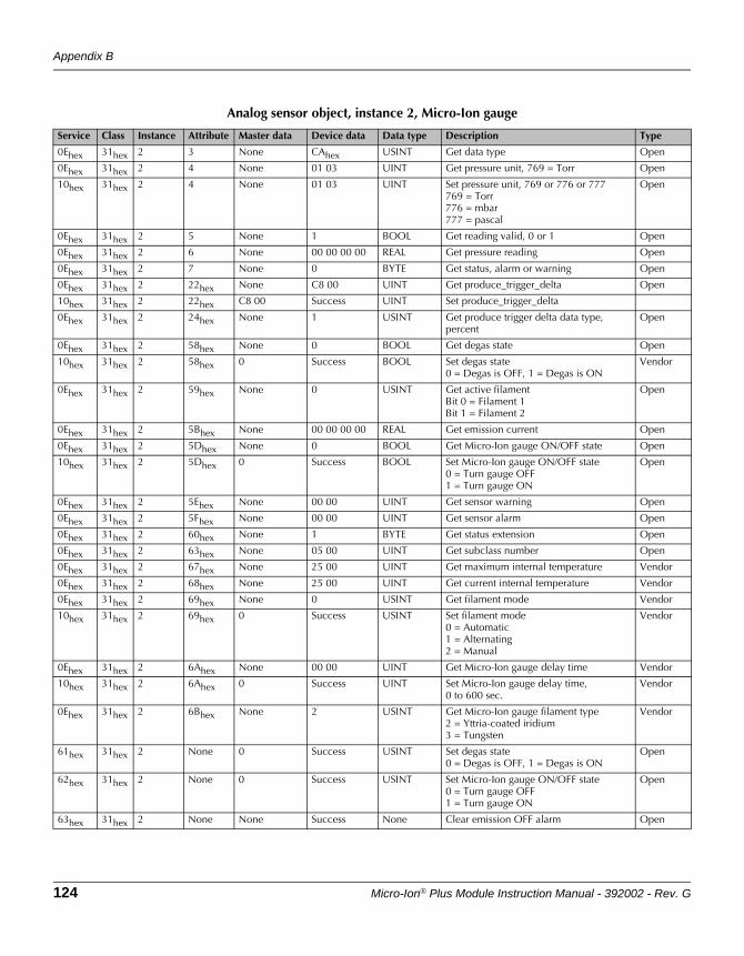
Appendix B
124 Micro-Ion® Plus Module Instruction Manual - 392002 - Rev. G
Analog sensor object, instance 2, Micro-Ion gauge
Service Class Instance Attribute Master data Device data Data type Description Type
0Ehex 31hex 2 3 None CAhex USINT Get data type Open
0Ehex 31hex 2 4 None 01 03 UINT Get pressure unit, 769 = Torr Open
10hex 31hex 2 4 None 01 03 UINT Set pressure unit, 769 or 776 or 777769 = Torr776 = mbar777 = pascal
Open
0Ehex 31hex 2 5 None 1 BOOL Get reading valid, 0 or 1 Open
0Ehex 31hex 2 6 None 00 00 00 00 REAL Get pressure reading Open
0Ehex 31hex 2 7 None 0 BYTE Get status, alarm or warning Open
0Ehex 31hex 2 22hex None C8 00 UINT Get produce_trigger_delta Open
10hex 31hex 2 22hex C8 00 Success UINT Set produce_trigger_delta
0Ehex 31hex 2 24hex None 1 USINT Get produce trigger delta data type, percent
Open
0Ehex 31hex 2 58hex None 0 BOOL Get degas state Open
10hex 31hex 2 58hex 0 Success BOOL Set degas state0 = Degas is OFF, 1 = Degas is ON
Vendor
0Ehex 31hex 2 59hex None 0 USINT Get active filamentBit 0 = Filament 1Bit 1 = Filament 2
Open
0Ehex 31hex 2 5Bhex None 00 00 00 00 REAL Get emission current Open
0Ehex 31hex 2 5Dhex None 0 BOOL Get Micro-Ion gauge ON/OFF state Open
10hex 31hex 2 5Dhex 0 Success BOOL Set Micro-Ion gauge ON/OFF state0 = Turn gauge OFF1 = Turn gauge ON
Open
0Ehex 31hex 2 5Ehex None 00 00 UINT Get sensor warning Open
0Ehex 31hex 2 5Fhex None 00 00 UINT Get sensor alarm Open
0Ehex 31hex 2 60hex None 1 BYTE Get status extension Open
0Ehex 31hex 2 63hex None 05 00 UINT Get subclass number Open
0Ehex 31hex 2 67hex None 25 00 UINT Get maximum internal temperature Vendor
0Ehex 31hex 2 68hex None 25 00 UINT Get current internal temperature Vendor
0Ehex 31hex 2 69hex None 0 USINT Get filament mode Vendor
10hex 31hex 2 69hex 0 Success USINT Set filament mode0 = Automatic1 = Alternating2 = Manual
Vendor
0Ehex 31hex 2 6Ahex None 00 00 UINT Get Micro-Ion gauge delay time Vendor
10hex 31hex 2 6Ahex 0 Success UINT Set Micro-Ion gauge delay time,0 to 600 sec.
Vendor
0Ehex 31hex 2 6Bhex None 2 USINT Get Micro-Ion gauge filament type2 = Yttria-coated iridium3 = Tungsten
Vendor
61hex 31hex 2 None 0 Success USINT Set degas state0 = Degas is OFF, 1 = Degas is ON
Open
62hex 31hex 2 None 0 Success USINT Set Micro-Ion gauge ON/OFF state0 = Turn gauge OFF1 = Turn gauge ON
Open
63hex 31hex 2 None None Success None Clear emission OFF alarm Open
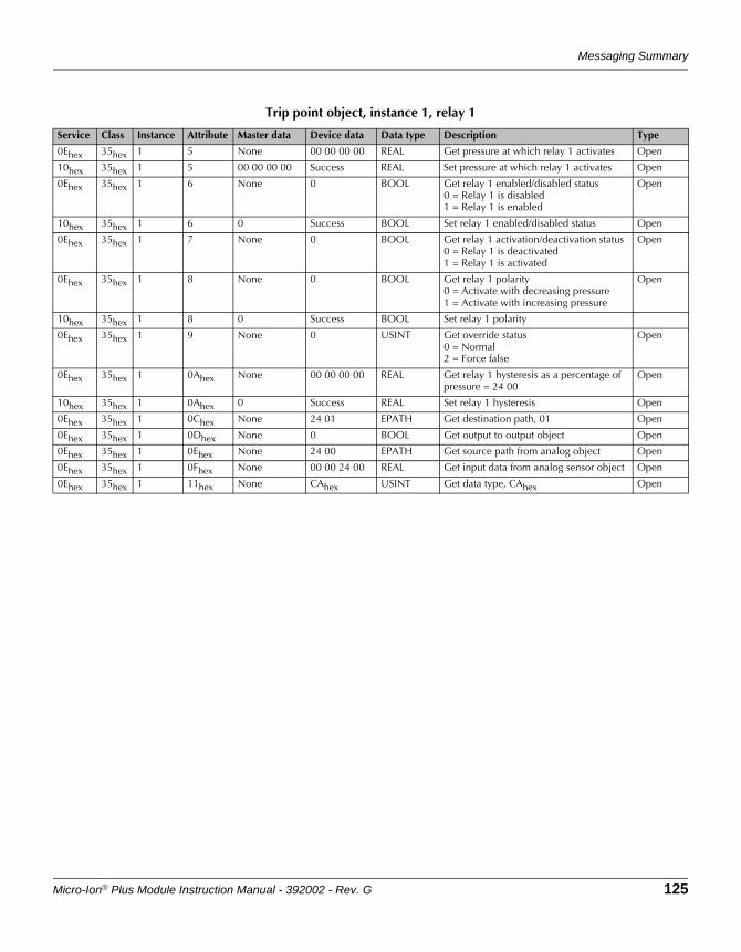
Messaging Summary
Micro-Ion® Plus Module Instruction Manual - 392002 - Rev. G 125
Trip point object, instance 1, relay 1
Service Class Instance Attribute Master data Device data Data type Description Type
0Ehex 35hex 1 5 None 00 00 00 00 REAL Get pressure at which relay 1 activates Open
10hex 35hex 1 5 00 00 00 00 Success REAL Set pressure at which relay 1 activates Open
0Ehex 35hex 1 6 None 0 BOOL Get relay 1 enabled/disabled status0 = Relay 1 is disabled1 = Relay 1 is enabled
Open
10hex 35hex 1 6 0 Success BOOL Set relay 1 enabled/disabled status Open
0Ehex 35hex 1 7 None 0 BOOL Get relay 1 activation/deactivation status0 = Relay 1 is deactivated1 = Relay 1 is activated
Open
0Ehex 35hex 1 8 None 0 BOOL Get relay 1 polarity0 = Activate with decreasing pressure1 = Activate with increasing pressure
Open
10hex 35hex 1 8 0 Success BOOL Set relay 1 polarity
0Ehex 35hex 1 9 None 0 USINT Get override status0 = Normal2 = Force false
Open
0Ehex 35hex 1 0Ahex None 00 00 00 00 REAL Get relay 1 hysteresis as a percentage of pressure = 24 00
Open
10hex 35hex 1 0Ahex 0 Success REAL Set relay 1 hysteresis Open
0Ehex 35hex 1 0Chex None 24 01 EPATH Get destination path, 01 Open
0Ehex 35hex 1 0Dhex None 0 BOOL Get output to output object Open
0Ehex 35hex 1 0Ehex None 24 00 EPATH Get source path from analog object Open
0Ehex 35hex 1 0Fhex None 00 00 24 00 REAL Get input data from analog sensor object Open
0Ehex 35hex 1 11hex None CAhex USINT Get data type, CAhex Open
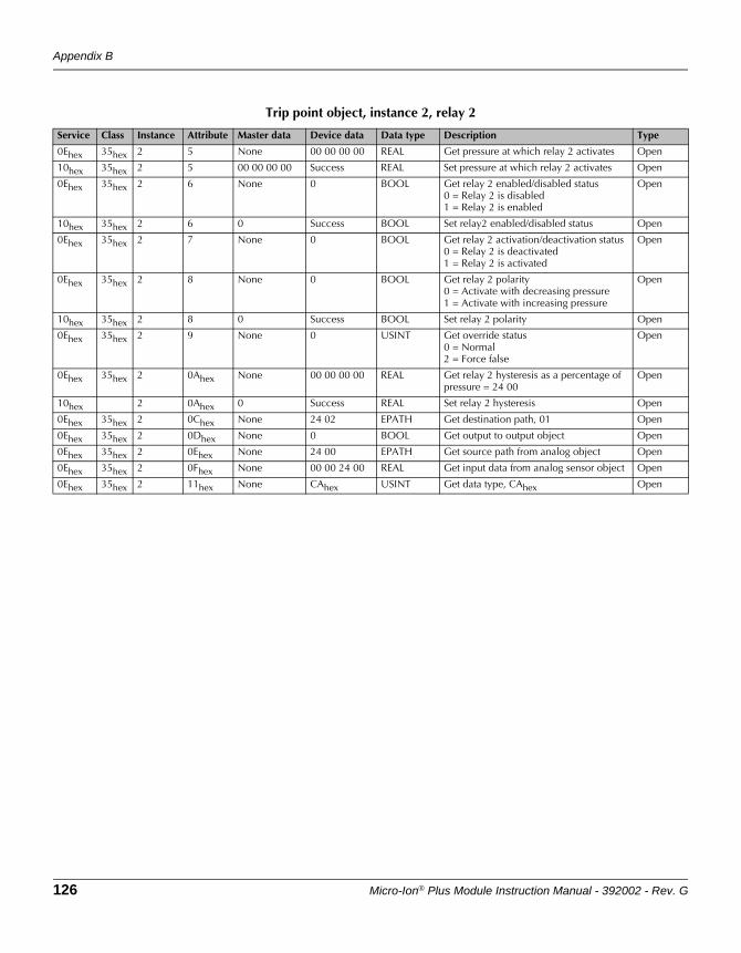
Appendix B
126 Micro-Ion® Plus Module Instruction Manual - 392002 - Rev. G
Trip point object, instance 2, relay 2
Service Class Instance Attribute Master data Device data Data type Description Type
0Ehex 35hex 2 5 None 00 00 00 00 REAL Get pressure at which relay 2 activates Open
10hex 35hex 2 5 00 00 00 00 Success REAL Set pressure at which relay 2 activates Open
0Ehex 35hex 2 6 None 0 BOOL Get relay 2 enabled/disabled status0 = Relay 2 is disabled1 = Relay 2 is enabled
Open
10hex 35hex 2 6 0 Success BOOL Set relay2 enabled/disabled status Open
0Ehex 35hex 2 7 None 0 BOOL Get relay 2 activation/deactivation status0 = Relay 2 is deactivated1 = Relay 2 is activated
Open
0Ehex 35hex 2 8 None 0 BOOL Get relay 2 polarity0 = Activate with decreasing pressure1 = Activate with increasing pressure
Open
10hex 35hex 2 8 0 Success BOOL Set relay 2 polarity Open
0Ehex 35hex 2 9 None 0 USINT Get override status0 = Normal2 = Force false
Open
0Ehex 35hex 2 0Ahex None 00 00 00 00 REAL Get relay 2 hysteresis as a percentage of pressure = 24 00
Open
10hex 2 0Ahex 0 Success REAL Set relay 2 hysteresis Open
0Ehex 35hex 2 0Chex None 24 02 EPATH Get destination path, 01 Open
0Ehex 35hex 2 0Dhex None 0 BOOL Get output to output object Open
0Ehex 35hex 2 0Ehex None 24 00 EPATH Get source path from analog object Open
0Ehex 35hex 2 0Fhex None 00 00 24 00 REAL Get input data from analog sensor object Open
0Ehex 35hex 2 11hex None CAhex USINT Get data type, CAhex Open
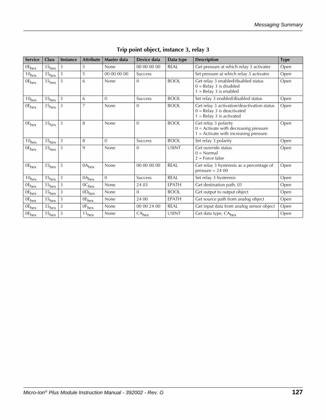
Messaging Summary
Micro-Ion® Plus Module Instruction Manual - 392002 - Rev. G 127
Trip point object, instance 3, relay 3
Service Class Instance Attribute Master data Device data Data type Description Type
0Ehex 35hex 3 5 None 00 00 00 00 REAL Get pressure at which relay 3 activates Open
10hex 35hex 3 5 00 00 00 00 Success Set pressure at which relay 3 activates Open
0Ehex 35hex 3 6 None 0 BOOL Get relay 3 enabled/disabled status0 = Relay 3 is disabled1 = Relay 3 is enabled
Open
10hex 35hex 3 6 0 Success BOOL Set relay 3 enabled/disabled status Open
0Ehex 35hex 3 7 None 0 BOOL Get relay 3 activation/deactivation status0 = Relay 3 is deactivated1 = Relay 3 is activated
Open
0Ehex 35hex 3 8 None 0 BOOL Get relay 3 polarity0 = Activate with decreasing pressure1 = Activate with increasing pressure
Open
10hex 35hex 3 8 0 Success BOOL Set relay 3 polarity Open
0Ehex 35hex 3 9 None 0 USINT Get override status0 = Normal2 = Force false
Open
0Ehex 35hex 3 0Ahex None 00 00 00 00 REAL Get relay 3 hysteresis as a percentage of pressure = 24 00
Open
10hex 35hex 3 0Ahex 0 Success REAL Set relay 3 hysteresis Open
0Ehex 35hex 3 0Chex None 24 03 EPATH Get destination path, 01 Open
0Ehex 35hex 3 0Dhex None 0 BOOL Get output to output object Open
0Ehex 35hex 3 0Ehex None 24 00 EPATH Get source path from analog object Open
0Ehex 35hex 3 0Fhex None 00 00 24 00 REAL Get input data from analog sensor object Open
0Ehex 35hex 3 11hex None CAhex USINT Get data type, CAhex Open
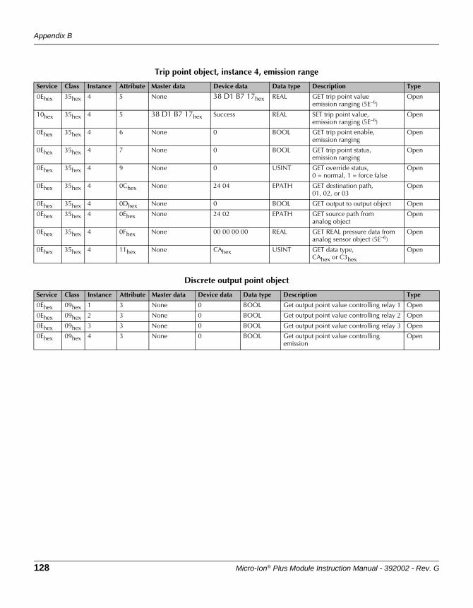
Appendix B
128 Micro-Ion® Plus Module Instruction Manual - 392002 - Rev. G
Trip point object, instance 4, emission range
Service Class Instance Attribute Master data Device data Data type Description Type
0Ehex 35hex 4 5 None 38 D1 B7 17hex REAL GET trip point valueemission ranging (5E–6)
Open
10hex 35hex 4 5 38 D1 B7 17hex Success REAL SET trip point value,emission ranging (5E–6)
Open
0Ehex 35hex 4 6 None 0 BOOL GET trip point enable,emission ranging
Open
0Ehex 35hex 4 7 None 0 BOOL GET trip point status,emission ranging
Open
0Ehex 35hex 4 9 None 0 USINT GET override status,0 = normal, 1 = force false
Open
0Ehex 35hex 4 0Chex None 24 04 EPATH GET destination path,01, 02, or 03
Open
0Ehex 35hex 4 0Dhex None 0 BOOL GET output to output object Open
0Ehex 35hex 4 0Ehex None 24 02 EPATH GET source path from analog object
Open
0Ehex 35hex 4 0Fhex None 00 00 00 00 REAL GET REAL pressure data fromanalog sensor object (5E–6)
Open
0Ehex 35hex 4 11hex None CAhex USINT GET data type,CAhex or C3hex
Open
Discrete output point object
Service Class Instance Attribute Master data Device data Data type Description Type
0Ehex 09hex 1 3 None 0 BOOL Get output point value controlling relay 1 Open
0Ehex 09hex 2 3 None 0 BOOL Get output point value controlling relay 2 Open
0Ehex 09hex 3 3 None 0 BOOL Get output point value controlling relay 3 Open
0Ehex 09hex 4 3 None 0 BOOL Get output point value controlling emission
Open
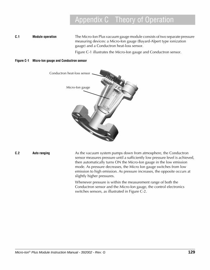
Micro-Ion® Plus Module Instruction Manual - 392002 - Rev. G 129
Appendix C Theory of Operation
C.1 Module operation The Micro-Ion Plus vacuum gauge module consists of two separate pressure measuring devices: a Micro-Ion gauge (Bayard-Alpert type ionization gauge) and a Conductron heat-loss sensor.
Figure C-1 illustrates the Micro-Ion gauge and Conductron sensor.
Figure C-1 Micro-Ion gauge and Conductron sensor
C.2 Auto ranging As the vacuum system pumps down from atmosphere, the Conductron sensor measures pressure until a sufficiently low pressure level is achieved, then automatically turns ON the Micro-Ion gauge in the low emission mode. As pressure decreases, the Micro Ion gauge switches from low emission to high emission. As pressure increases, the opposite occurs at slightly higher pressures.
Whenever pressure is within the measurement range of both the Conductron sensor and the Micro-Ion gauge, the control electronics switches sensors, as illustrated in Figure C-2.
Micro-Ion gauge
Conductron heat-loss sensor
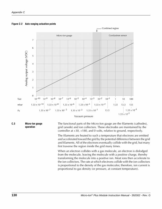
Appendix C
130 Micro-Ion® Plus Module Instruction Manual - 392002 - Rev. G
Figure C-2 Auto ranging actuation points
C.3 Micro-Ion gauge operation
The functional parts of the Micro-Ion gauge are the filaments (cathodes), grid (anode) and ion collectors. These electrodes are maintained by the controller at +30, +180, and 0 volts, relative to ground, respectively.
The filaments are heated to such a temperature that electrons are emitted and accelerated toward the grid by the potential difference between the grid and filaments. All of the electrons eventually collide with the grid, but many first traverse the region inside the grid many times.
When an electron collides with a gas molecule, an electron is dislodged from the molecule, leaving the molecule with a positive charge, thereby transforming the molecule into a positive ion. Most ions then accelerate to the ion collectors. The rate at which electrons collide with the ion collectors is proportional to the density of the gas molecules; therefore, ion current is proportional to gas density (or pressure, at constant temperature).
Theory of Operation
Micro-Ion® Plus Module Instruction Manual - 392002 - Rev. G 131
The amount of ion current for a given emission current and pressure depends on the Micro-Ion gauge design. This gives rise to the definition of ionization gauge sensitivity, frequently denoted by “S”:
The module electronics for the gauge varies the heating current to the filament to maintain a constant electron emission and measures the ion current to the ion collectors. The pressure is then calculated from these data.
Micro-Ion gauge degas is accomplished by increasing the emission current to 15 mA and raising the grid bias to 250 Vdc, resulting in an increased grid temperature to drive off adsorbed gases.
C.4 Conductron sensor operation
The Conductron heat-loss sensor uses Granville-Phillips’ Conductron sensor proprietary geometry and control circuitry. The sensor is comprised of two coplaner wire elements: a sensing wire, and a compensating wire that corrects for ambient conditions. The resistance of the sensing wire increases as its temperature increases. The controller continually adjusts a heating current that flows through the sensing wire to keep the sensor at a regulated temperature.
If pressure increases, the heat loss through gas conduction from the sensor increases, and the sensor temperature decreases, causing the resistance of the sensor to decrease. As this occurs, an error amplifier senses a change in the resistance differential between the sensor element and the compensation element, and generates an increase in the heating current through the sensor. The increased current through the sensor increases its temperature (and its resistance), and the resistance differential between the two elements is reestablished at a higher sensor input voltage and current. When calibrated, using a series of pressures and ambient temperatures, the input voltage and current are measured as an indication of the system pressure.
S Ion currentEmission current Pressure×----------------------------------------------------------------------=

132 Micro-Ion® Plus Module Instruction Manual - 392002 - Rev. G
Micro-Ion® Plus Module Instruction Manual - 392002 - Rev. G 133
Index
AAddress offset 75Analog output
calibration 33functions 29Micro-Ion gauge degas 33Micro-Ion gauge ON/OFF 32operational tasks 29reading pressure 31wiring for 21
AppendixesMessaging Summary 117Specifications 111Theory of Operation 129
Assembling and connecting wiring 19Atmospheric pressure 12Attaching module to vacuum chamber 18Auto ranging 129
BBaud rate 76
CCalibration
atmospheric pressure 34, 60, 91vacuum pressure 34, 60, 92
Cautions and warnings 9CE Mark 20Chapters
Analog Operation 29Before You Begin 9DeviceNet Operation 35Installation 15Maintenance 101Operation Overview 25Optional Display 99RS-485 Operation 67
Conductron sensorspecifications 114theory of operation 131
Customer service 14, 101Customer Service & Support
Contact Information 3, 138
DDamage requiring service 101Definitions of terms
address 13atmospheric pressure 12attribute 13BOOL data 14BYTE data 14class 13Conductron sensor 12data rate 13device data 13device type 14electronics assembly 12EPATH 14explicit messages 13gauge assembly 12instance 13INT data 14master data 13Micro-Ion gauge 12module 12polled I/O messages 13REAL data 14SSTRING data 14STRUCT data 14UINT data 14USINT data 14vacuum pressure 12WORD data 14
degas 57, 58, 69, 88, 104DeviceNet data conversion 44DeviceNet messaging summary
explicit messages 118polled I/O 117
DeviceNet outputcalibration 60communication configuration 41data conversion 44error codes 63, 105factory defaults 62functions 35get active filament 57get Micro-Ion gauge degas ON/OFF state 58get Micro-Ion gauge ON/OFF status 54
Index
134 Micro-Ion® Plus Module Instruction Manual - 392002 - Rev. G
get relay activation/deactivation status 52get relay enable/disable status 52get relay trip point 52get revision levels 61get temperature 47get vacuum pressure 45initiate or terminate Micro-Ion gauge degas 57Micro-Ion gauge controls 53Micro-Ion gauge filament mode 55operational tasks 37pressure unit 44rate switch 39relays 47reset to power-up state 61set or get Micro-Ion gauge delay time 54set or get Micro-Ion gauge emission current 58set or get pressure unit 44set relay hysteresis 53status LEDs 39switches and indicators 38turn Micro-Ion gauge ON or OFF 53wiring 22
DeviceNet protocolfor Micro-Ion Plus module 37performance with 36
Dimensions of module 116
EElectronics assembly 12Error conditions
DeviceNet 63, 105module status hexadecimal bits 94, 105module status strings 92, 105optional display 100RS-485 69, 104symptoms, causes, and solutions 103
Explicit messages 118
FFactory defaults 62, 97Fittings
ConFlat flange 18KF flange 18VCR type 18
GGauge assembly
definition of 12replacement of 109
IImplosion / Explosion 10Installation
analog output 21assembling and connecting wiring 19attaching module to vacuum chamber 18CE mark compliance 20ConFlat flange 18connecting cable 19DeviceNet wiring 22gauge OFF/degas wiring 21grounding 22installing pressure relief devices 15KF flange 18locating module 16module components 15module power supply 20procedure 16radio frequency interference (RFI) 24relay wiring 21RS-485 wiring 21VCR type fitting 18
LLETHAL VOLTAGES 10
MMaintenance
damage requiring service 101Micro-Ion gauge continuity test 107overpressure shutdown 106replacing gauge assembly 109returning damaged module 109symptoms, causes, and solutions 103troubleshooting 102troubleshooting precautions 102
Micro-Ion gaugeautomatic filament selection 28continuity test 107controls 53
Index
Micro-Ion® Plus Module Instruction Manual - 392002 - Rev. G 135
degas 33, 57, 88degas ON/OFF state 58, 88degas time 89delay ON/OFF state 82delay time 54, 83emission current 58, 89, 91filament mode 55, 84filament status 57, 88ON/OFF status 54, 80pressure indication when OFF 81theory of operation 130turning ON or OFF 32, 53, 80wiring for 21
Modulecomponents 15dimensions 116power supply 20reading firmware version 97resetting to factory defaults 97resetting to power-up state 61, 96returning damaged 109
OOperation
analog 25analog output 29automatic filament selection 28DeviceNet 25DeviceNet output 35preparing to operate module 29, 35, 67RS-485 27RS-485 output 67
Optional displaycapabilities 99error conditions 100resolution 99
Overpressure shutdown 106
PPolled I/O 117Pressure
data conversion 44measurement specifications 111reading vacuum 31, 45, 76
Pressure relief devices 15
Pressure unitreading 44, 76, 99setting 44, 76
RRadio frequency interference (RFI) 24Rate switch 39Reading and following instructions 11Relays
activation/deactivation status 52, 79configuring 47enabled/disabled status 52, 79hysteresis 53, 77specifications 113wiring for 21
RS-485 command set 72RS-485 command structure 71RS-485 command symbols 71RS-485 commands 71
DG 27, 88DGS 27, 88DGT 27, 89FAC 27, 97IDT 27, 83IG 27, 80IGM 27, 81IGS 27, 80IOD 27, 82PC 27PCE 27, 79RD 27, 76RE 27, 91RF 27, 88RPCS 27, 79RS 27, 92RST 27, 96RSX 27, 94RU 27, 76SA 27, 75SB 27, 76SER 27, 89SF 27, 84SU 27, 76TLU 27, 74TS 27, 91
136 Micro-Ion® Plus Module Instruction Manual - 392002 - Rev. G
TZ 27, 92UNL 27, 74VER 27, 97yuiop 27, 76
RS-485 outputcommand set 72command structure 71commands 71data timing and response 70defaults 76error codes 104error responses 69functions 67module status strings 92operational tasks 69physical layer 68status hexadecimal bits 94status LEDs 30wiring for 21
SSet address offset 75setting baud rate 76Specifications
Conductron heat-loss sensor 114electrical connectors 115optional trip point relays 113outputs and indicators 112pressure measurement 111temperature 111
Status LEDs 30, 39Symbols in RS-485 commands 71System Grounding 10
TTemperature
specifications 111Theory of operation
auto ranging 129Conductron sensor 131Micro-Ion gauge 130module 129
Toggling locked functions 74Troubleshooting
precautions 102
symptoms, causes, and solutions 103
UUnlocking interface functions 74
VVacuum pressure 12
WWiring
analog output 21assembling and connecting 19CE Mark compliance 20connecting cable 19DeviceNet 22gauge OFF/degas 21grounding 22module power supply 20relays 21RS-485 output 21specifications for electrical connectors 115

.
Granville-Phillips® Series 392 Micro-Ion® Plus Two-Sensor Combination Vacuum Gauge Modulewith DeviceNetTM and RS-485 Interface,and Analog Output
Instruction manual part number 392002
Revision G - January 2015
Series 392
Instruction Manual
For Customer Service or Technical Support 24 hours per day, 7 days per week, every day of the year including holidays:Phone: +1-800-227-8766 or +1-303-652-4691
MKS, Granville-Phillips Division6450 Dry Creek ParkwayLongmont, CO 80503 USA
Phone: 1-303-652-4691 or 1-800-776-6543 FAX: 1-303-652-2844Email: [email protected]
Corporate OfficeMKS Instruments, Inc.2 Tech Drive, Suite 201Andover, MA 01810 USA
Phone: 1-978-645-5500www.mksinst.com