Embed Size (px)
Citation preview
SingleRANSRAN11.1
3900 Series Base StationConfiguration Principles
Issue 05
Date 2016-08-01
HUAWEI TECHNOLOGIES CO., LTD.
Copyright © Huawei Technologies Co., Ltd. 2016. All rights reserved.No part of this document may be reproduced or transmitted in any form or by any means without prior writtenconsent of Huawei Technologies Co., Ltd. Trademarks and Permissions
and other Huawei trademarks are trademarks of Huawei Technologies Co., Ltd.All other trademarks and trade names mentioned in this document are the property of their respectiveholders. NoticeThe purchased products, services and features are stipulated by the contract made between Huawei and thecustomer. All or part of the products, services and features described in this document may not be within thepurchase scope or the usage scope. Unless otherwise specified in the contract, all statements, information,and recommendations in this document are provided "AS IS" without warranties, guarantees orrepresentations of any kind, either express or implied.
The information in this document is subject to change without notice. Every effort has been made in thepreparation of this document to ensure accuracy of the contents, but all statements, information, andrecommendations in this document do not constitute a warranty of any kind, express or implied.
Huawei Technologies Co., Ltd.Address: Huawei Industrial Base
Bantian, LonggangShenzhen 518129People's Republic of China
Website: http://www.huawei.com
Email: [email protected]
Issue 05 (2016-08-01) Huawei Proprietary and ConfidentialCopyright © Huawei Technologies Co., Ltd.
i
Contents
1 3900 Series Base Station Configuration Principles................................................................. 11.1 Changes in 3900 Series Base Station Configuration Principles..................................................................................... 2
2 Overview......................................................................................................................................... 4
3 Version Difference........................................................................................................................ 6
4 Product Configuration..................................................................................................................94.1 3900 Series Base Station Configurations..................................................................................................................... 104.1.1 BTS3900 Configurations...........................................................................................................................................104.1.2 BTS3900A Configurations........................................................................................................................................ 124.1.3 BTS3900L Configurations........................................................................................................................................ 164.1.4 BTS3900AL Configurations......................................................................................................................................184.1.5 DBS3900 Configurations.......................................................................................................................................... 194.1.6 BTS3900C Configurations........................................................................................................................................ 204.2 BBU Configurations..................................................................................................................................................... 214.2.1 BBU Case Configurations......................................................................................................................................... 214.2.2 Typical BBU Configurations..................................................................................................................................... 244.2.3 BBU Board Configurations....................................................................................................................................... 304.2.3.1 GSM BBU Board Configurations...........................................................................................................................304.2.3.2 UMTS BBU Board Configurations........................................................................................................................ 334.2.3.3 LTE BBU Board Configurations............................................................................................................................ 344.2.3.4 Common Board Configurations..............................................................................................................................354.2.3.5 Clock and Transmission Board Configurations......................................................................................................444.3 RF Module Configurations...........................................................................................................................................484.3.1 RF Module Configurations........................................................................................................................................484.3.2 RF Modules Working at Band 31 (450 MHz)........................................................................................................... 504.3.3 RF Modules Working at Band 8 (900 MHz)............................................................................................................. 504.3.4 RF Modules Working at Band 3 (1800 MHz)........................................................................................................... 584.3.5 RF Modules Working at Band 5 (850 MHz)............................................................................................................. 654.3.6 RF Modules Working at Band 2 (1900 MHz)........................................................................................................... 694.3.7 RF Modules Working at Band 1 (2100 MHz)........................................................................................................... 734.3.8 RF Modules Working at Band 7 (2600 MHz)........................................................................................................... 814.3.9 RF Modules Working at Band 4 (AWS)....................................................................................................................844.3.10 RF Modules Working at Band 66 (AWS-3).............................................................................................................86
SingleRAN3900 Series Base Station Configuration Principles Contents
Issue 05 (2016-08-01) Huawei Proprietary and ConfidentialCopyright © Huawei Technologies Co., Ltd.
ii
4.3.11 RF Modules Working at Band 12 (700 MHz)......................................................................................................... 874.3.12 RF Modules Working at Band 13 (700 MHz)......................................................................................................... 884.3.13 RF Modules Working at Band 20 (800 MHz)......................................................................................................... 884.3.14 RF Modules Working at Band 28 (APT700 MHz)..................................................................................................904.4 AAU Configurations.....................................................................................................................................................924.4.1 AAU3910 Configurations..........................................................................................................................................924.4.2 AAU3902 Configurations..........................................................................................................................................974.4.3 AAU3940 Configurations..........................................................................................................................................994.4.4 AAU3920 Configurations........................................................................................................................................1014.4.5 AAU3911 Configurations........................................................................................................................................1034.4.6 AAU3961 Configurations........................................................................................................................................1134.5 Configurations of Enhanced Cabinets........................................................................................................................ 1164.6 Power Module Configurations....................................................................................................................................1264.7 RET Module Configurations...................................................................................................................................... 1384.8 Hardware License Configuration................................................................................................................................1394.8.1 Hardware License Configuration of GSM Base Stations........................................................................................1394.8.2 Hardware License Configuration of UMTS Base Stations..................................................................................... 1414.8.3 Hardware License Configuration of LTE Base Stations..........................................................................................1444.8.4 License Configurations of Multimode Base Stations.............................................................................................. 1494.9 Equipment and Product Auxiliary Material Configuration........................................................................................ 1534.9.1 Installation Auxiliary Materials...............................................................................................................................1534.9.2 Auxiliary Site Materials...........................................................................................................................................172
5 Typical Configurations and Capacity Expansion................................................................1855.1 Typical Configurations............................................................................................................................................... 1865.1.1 Single Mode.............................................................................................................................................................1865.1.2 GU Dual Mode........................................................................................................................................................ 1875.1.3 GL Dual Mode.........................................................................................................................................................1885.1.4 UL Dual Mode.........................................................................................................................................................1895.1.5 GUL Triple Modes...................................................................................................................................................1905.2 Capacity Expansion Principles................................................................................................................................... 192
SingleRAN3900 Series Base Station Configuration Principles Contents
Issue 05 (2016-08-01) Huawei Proprietary and ConfidentialCopyright © Huawei Technologies Co., Ltd.
iii
1 3900 Series Base Station Configuration
Principles
OverviewThis document describes the principles for configuring hardware in 3900 series base stations.Based on the specific configuration requirements in this document, the quantities ofcomponents to be configured in a base station can be calculated and planned.
The exteriors of components or cables in this document are for reference only. The actualexteriors may be different.
Product VersionProduct Solution Version Product Version
BTS3900 l SRAN11.1l GBSS18.1l RAN18.1l eRAN11.1
V100R011C10
BTS3900A
BTS3900L
BTS3900AL
DBS3900
BTS3900C
Intended AudienceThis document is intended for:
l Technical support engineersl System engineers
1.1 Changes in 3900 Series Base Station Configuration Principles
SingleRAN3900 Series Base Station Configuration Principles 1 3900 Series Base Station Configuration Principles
Issue 05 (2016-08-01) Huawei Proprietary and ConfidentialCopyright © Huawei Technologies Co., Ltd.
1
1.1 Changes in 3900 Series Base Station ConfigurationPrinciples
This chapter describes changes in 3900 Series Base Station Configuration Principles of eachversion.
05 (2016-08-01)
Compared with Issue 04 (2016-06-25) of SRAN11.1, this issue does not include any newtopics or exclude any topics.
Compared with Issue 04 (2016-06-25) of SRAN11.1, this issue includes the followingchanges.
Topic Change Description
4.3.7 RF Modules Working at Band 1(2100 MHz)
Added the RRU3953.
04 (2016-06-25)
Compared with Issue 03 (2016-05-31) of SRAN11.1, this issue does not include any newtopics or exclude any topics.
Compared with Issue 03 (2016-05-31) of SRAN11.1, this issue includes the followingchanges.
Topic Change Description
4.3.7 RF Modules Working at Band 1(2100 MHz)
Added the RRU3971.
03 (2016-05-31)
Compared with Issue 02 (2016-04-20) of SRAN11.1, this issue does not include any newtopics or exclude any topics.
Compared with Issue 02 (2016-04-20) of SRAN11.1, this issue includes the followingchanges.
Topic Change Description
4.2.3.4 Common Board Configurations Added the UMPTe and UBBPe.
SingleRAN3900 Series Base Station Configuration Principles 1 3900 Series Base Station Configuration Principles
Issue 05 (2016-08-01) Huawei Proprietary and ConfidentialCopyright © Huawei Technologies Co., Ltd.
2
02 (2016-04-20)Compared with Issue 01 (2016-03-07) of SRAN11.1, this issue includes the following newtopic:
4.4.6 AAU3961 Configurations
Compared with Issue 01 (2016-03-07) of SRAN11.1, this issue includes the followingchanges.
Topic Change Description
4.4.3 AAU3940 Configurations Added the AAU3940 operating in AWS andPCS.
Compared with Issue 01 (2016-03-07) of SRAN11.1, this issue does not exclude any topics.
01 (2016-03-07)Compared with Draft A (2015-12-30) of SRAN11.1, this issue does not include any changes.
Draft A (2015-12-30)Compared with Issue 05 (2015-10-30) of SRAN10.1, this issue includes the following newtopic:
Topic Change Description
4.3.3 RF Modules Working at Band 8(900 MHz)
Added the MRFU V6.
4.3.6 RF Modules Working at Band 2(1900 MHz)
Added the RRU3971.
4.3.7 RF Modules Working at Band 1(2100 MHz)
Added the RRU3952 and RRU3958.
4.3.9 RF Modules Working at Band 4(AWS)
Added the RRU3971.
Hardware License Configurations ofMultimode Base Stations
Updated descriptions of multimode licensesfor RRUs and AAUs.
Compared with Issue 05 (2015-10-30) of SRAN10.1, this issue does not include any changesor exclude any topics.
SingleRAN3900 Series Base Station Configuration Principles 1 3900 Series Base Station Configuration Principles
Issue 05 (2016-08-01) Huawei Proprietary and ConfidentialCopyright © Huawei Technologies Co., Ltd.
3
2 Overview
This document describes the principles for configuring single-mode and multimode 3900series base stations.
NOTE
Definition for high-power RRUs/RFUs, ultra-high-power RRUs, and low-power RRUs/RFUs are asfollows:l For each low-power RFU, the sum of the maximum transmit power of all channels is less than or
equal to 125 W.l For each high-power RFU, the sum of the maximum transmit power of all channels is equal to 160
W.l For each low-power RRU, the sum of the maximum transmit power of all channels is less than or
equal to 80 W.l For each high-power RRU, the sum of the maximum transmit power of all channels is equal to 120
W.l For each ultra-high-power RRU, the sum of the maximum transmit power of all channels is equal to
160 W.
Introduction to 3900 Series Base Stations3900 series base stations, which use baseband units (BBUs) and RF modules as the maindevices, adopt the industry-leading modular design to support multiple RATs and applicationforms, and therefore are applicable to various installation scenarios, greatly reducing costs insite acquisition, capacity expansion, and environment protection during network deploymentand operation. In addition, 3900 series base stations support multiple solutions for evolutionfrom GSM to UMTS and then to LTE.
l The BBU supports multimode applications.When being configured with boards supporting GSM, UMTS, and LTE, a BBU cansupport these modes. In separate-MPT scenarios, one BBU supports two modes, and twoBBUs support three or four modes. In co-MPT scenarios, one BBU supports three orfour modes.
NOTE
The BBUs in this document include the BBU3900, BBU3910, and BBU3910A.
l RRUs and RFUs are radio frequency units and support multimode and multibandapplications.– To meet operators' requirements, the software defined radio (SDR) technology is
introduced, which enables RF modules to support any two or three modes among
SingleRAN3900 Series Base Station Configuration Principles 2 Overview
Issue 05 (2016-08-01) Huawei Proprietary and ConfidentialCopyright © Huawei Technologies Co., Ltd.
4
GSM, UMTS, and LTE using different software configurations. A base station canbe configured with single-mode RF modules of GSM, UMTS, and LTE andmultimode RF modules to support any single mode as well as two or three modesincluding GSM, UMTS, and LTE.
– RF modules working in different frequency bands can be used together to supportmulti-band applications.
– High-power RFUs are as follows: MRFUd/MRFUe/WRFUd/WRFUe/LRFUe/CRFUd/CRFUe. These RFUs are used together with the BTS3900 (Ver.C)/(Ver.D)/(Ver.E) cabinets.
– High-power RRUs are as follows: RRU3829/RRU3929/RRU3942/RRU3841/RRU3961/RRU3832/RRU3839/RRU3939/RRU3952/RRU3959/RRU3262/RRU3953/RRU3962/RRU3962d/RRU3965/RRU3965d. These RRUs are usedtogether with the DCDU-11B or DCDU-12B. Ultra-high-power RRUs are usedtogether with the DCDU-12B. Except the preceding RRUs, other RRUs are low-power ones. In addition, the 2100 MHz AAU3910, AWS AAU3910, AAU3920,AAU3940, and AAU3911 are also high-power modules.
– Blade RRUs are as follows: RRU3962/RRU3965/RRU3936/RRU3938/RRU3939/RRU3953/RRU3952/RRU3959/RRU3958/RRU3971/RRU3668/RRU3824/RRU3826/RRU3838/RRU3832/RRU3839, and RRU3268/RRU3260/RRU3262/RRU3249/RRU3269/RRU3281.
Description
The following table describes the meanings of some symbols and phrases in this document.
Table 2-1 Symbol meanings
Symbol Meaning
& It is used between different modes in a separate-MPT base station. For example,GSM&UMTS, which can be shortened to GU, indicates a separate-MPT GU dual-modebase station.
* It is used between different modes in a co-MPT base station. For example, GSM*UMTS,which can be shortened to G*U, indicates a co-MPT GU dual-mode base station.
+ It is used between different modes for the two BBUs in a separate-MPT base station. Forexample, GSM&UMTS+LTE, which can be shortened to GU+L, indicates a separate-MPTGUL triple-mode base station.
[] [] contains co-MPT modes. For example, GSM[UMTS*LTE] can be shortened to G[U*L].
_ The underline and letters following a board's name is the actual configuration of the boardsuch as the co-MPT configuration of a UMPT and the baseband concurrency configurationof a UBBP. For example, UMPT_GUL refers to a UMPT supporting GUL triple modes;UBBP_UL refers to a UBBP supporting UL dual modes.
GU SDR GSM and UMTS share RF modules.
GL SDR GSM and LTE share RF modules.
UL SDR UMTS and LTE share RF modules.
GUL SDR GSM, UMTS, and LTE share RF modules.
SingleRAN3900 Series Base Station Configuration Principles 2 Overview
Issue 05 (2016-08-01) Huawei Proprietary and ConfidentialCopyright © Huawei Technologies Co., Ltd.
5
3 Version Difference
SRAN11.1
The single-mode versions for SRAN11.1 are GBSS18.1, RAN18.1, and eRAN11.1.Compared with SRAN11.0, SRAN11.1 includes the following changes:l Added the UMPTe (multimode main control board) and UBBPe (multimode baseband
processing board). The FE/GE surge protection package is not required when a UMPTeis configured.
l Added RF modules: 900 MHz 1x80 W MRFU V6 and 1800 MHz 1x80 W MRFU V6.l Added the following RF modules: 4x40 W RRU3971 working at AWS, 4x40 W
RRU3971 working at 1900 MHz, 4x40 W RRU3971 working at 2100 MHz, 2x60 WRRU3952 working at 2100 MHz, 2x60 W RRU3958 working at 2100 MHz, and 4x40 WRRU3281 working at 2600 MHz (delivered in SRAN11.1, supported from SRAN9.0).
l Added the AAU3940 working at AWS and PCS frequency bands and the AAU3961.l Added the OPM30M.
SRAN11.0
The single-mode versions for SRAN11.0 are GBSS18.0, RAN18.0, and eRAN11.0.Compared with SRAN10.1, SRAN11.0 includes the following changes:l Added Ver.E cabinets.l Added the GTMUc.l Added the MRFUd V6 working at 1800 MHz.l Added the LRFUe working at DD 800 MHz.
SRAN10.1
The single-mode versions for SRAN10.1 are GBSS17.1, RAN17.1, and eRAN8.1. Comparedwith SRAN10.0, SRAN10.1 includes the following changes:
l Added the AAU3920 and AAU3940.l Added the GTMUb to support SingleOM.l Added the following RF modules: 850 MHz 2T4R 2x60 W RRU3952 (delivered in
SRAN10.1, supported from SRAN8.0), 1900 MHz 2T4R 2x80 W RRU3953 (deliveredin SRAN10.1, supported from SRAN8.0), 1800 MHz 2T2R 2x60 W RRU3959
SingleRAN3900 Series Base Station Configuration Principles 3 Version Difference
Issue 05 (2016-08-01) Huawei Proprietary and ConfidentialCopyright © Huawei Technologies Co., Ltd.
6
(delivered in SRAN10.1, supported from SRAN8.0), 1800 MHz 2T2R 2x60 WRRU3959w (delivered in SRAN10.1, supported from SRAN8.0), 700 MHz 2T4R 2x60W RRU3262, 2600 MHz 2T2R 2x60 W LRFUe, 700 MHz band 12 RRU3249, and 700MHz band 12&13 RRU3269.
l Added the BBU3900A1 and BBU3910A2.l Added distributed Cloud BB scenarios.
SRAN10.0The single-mode versions for SRAN10.0 are GBSS17.0, RAN17.0, and eRAN8.0. Comparedwith SRAN9.0, SRAN10.0 includes the following changes:
l Added the BBU3910A3.l Added the AAU3911.l Added power modules: OPM50M and IBBS20D.l Added the USU3910 for Cloud BB.
SRAN9.0The single-mode versions for SRAN9.0 are GBSS16.0, RAN16.0, and eRAN7.0. Comparedwith SRAN8.0, SRAN9.0 includes the following changes:
l Added the AAU3902 working as a 1.8 A module in GL mode.l Added the UBBP and BBU3910. A BBU3910 can be installed in the following cabinets:
BTS3900 (Ver.D), BTS3900L (Ver.D), BTS3900A (Ver.D), APM30H (Ver.D), TMC11H(Ver.D), IMB03, OMB (Ver.C) (applies to DBS3900 and BTS3900C [Ver.C]), andBTS3900AL (Ver.A). Added the RRU3262 working in 2600 MHz and APT700MLRFUe.
l Added the multimode baseband license.l Added the ODM and OFD.
SRAN8.1The single-mode versions for SRAN8.1 are GBSS15.1, RAN15.1, and eRAN6.1. Comparedwith SRAN8.0, SRAN8.1 includes the following changes:
l Added the following RF modules: RRU3938 working at the EGSM, PGSM, and 1800MHz frequency bands and enhanced MRFUd working at the EGSM, PGSM, and 1800MHz frequency bands
l Added the RRU3268 working at 800 MHz for eRAN6.1.l Added the AAU3902 working as a 1.8 A module in LO mode.l Added the support for the GULT quadruple mode.
SRAN8.0The single-mode versions for SRAN8.0 are GBSS15.0, RAN15.0, and eRAN6.0. Comparedwith SRAN7.0, SRAN8.0 includes the following changes:
l Added the following BBU boards: UBRIb, UMPTb1, LBBPd3 (LTE basebandprocessing unit), UTRPa (UMTS transmission processing unit), and UBBPd1/UBBPd2/UBBPd3/UBBPd4 (UMTS baseband processing unit).
SingleRAN3900 Series Base Station Configuration Principles 3 Version Difference
Issue 05 (2016-08-01) Huawei Proprietary and ConfidentialCopyright © Huawei Technologies Co., Ltd.
7
l Added the AAU3910, which can serve as an active unit of 1800 MHz, 2100 MHz, 2600MHz, or AWS.
l Added the AAU3902 working at 2100 MHz.l Added the RRU3926 in GL mode.l Clarified the number of HSPA UEs that can be carried by a WBBP.l Added the GU/GL/UL/GUL co-MPT configurations.l Added the following RF modules: 2.6 GHz RRU3260, 2.6 GHz RRU3268, 1800 MHz
RRU3939, 850 MHz and 1900 MHz RRU3936, 1.8 GHz RRU3953, 1.8 GHzRRU3953w, and 900 MHz RRU3959.
l Added the AAU3910, which can serve as an active unit of 1800 MHz, 2100 MHz, 2600MHz, or AWS in SRAN8.0.
l Added the RRU3808 (AWS) in UL mode.l Added the scenario that a LampSite base station and a DBS3900 share BBUs.
SingleRAN3900 Series Base Station Configuration Principles 3 Version Difference
Issue 05 (2016-08-01) Huawei Proprietary and ConfidentialCopyright © Huawei Technologies Co., Ltd.
8
4 Product Configuration
This chapter describes the principles for configuring various components in 3900 series basestations.
3900 series base stations use modular design. A macro base station consists of the cabinet,BBU, and RF modules. The minimum configuration of a macro base station includes theminimum configurations of cabinets, baseband processing boards, main control boards, andRF modules. A distributed base station consists of the BBU and RF modules. The minimumconfiguration of a distributed base station includes the minimum configurations of basebandprocessing boards, main control boards, and RF modules. Baseband processing boards, RFmodules, and transmission ports can be expanded smoothly by adding new boards and RFmodules or licenses.
4.1 3900 Series Base Station Configurations
4.2 BBU Configurations
4.3 RF Module Configurations
4.4 AAU Configurations
4.5 Configurations of Enhanced Cabinets
4.6 Power Module Configurations
4.7 RET Module Configurations
4.8 Hardware License Configuration
4.9 Equipment and Product Auxiliary Material Configuration
SingleRAN3900 Series Base Station Configuration Principles 4 Product Configuration
Issue 05 (2016-08-01) Huawei Proprietary and ConfidentialCopyright © Huawei Technologies Co., Ltd.
9
4.1 3900 Series Base Station Configurations
4.1.1 BTS3900 ConfigurationsThis section describes the principles for configuring cabinets, BBUs, and RF modules in aBTS3900.
BTS3900 Configuration PrinciplesThe following table lists the BTS3900 configuration principles.
Table 4-1 BTS3900 configuration principles
Single-,Dual-, orTriple-Mode BaseStation
MaximumNumberofCabinets
Number ofBBUs
Maximum Number of RF Modules Description
Single- ordual-modebase station
2 1 l If the base station is configured with RFUs butwithout RRUs, a maximum of 12 RFUs are supported.
l If RFUs and RRUs are configured, a maximum of 12RFUs and 6 RRUs are supported.
-
Separate-MPT triple-mode basestation
2 2 If the base station is configured with RFUs but withoutRRUs, a maximum of 12 RFUs are supported.If RFUs and RRUs are configured:l A BTS3900 using the BTS3900 (Ver.B/Ver.C) cabinet
supports a maximum of 12 RFUs and 6 RRUs. TheDCDU supplying power to RRUs must be installed ona wall.
l A site using the Ver.D cabinet supports a maximum of12 RFUs, 6 high-power RRUs, and 3 low-powerRRUs. The DCDU supplying power to RRUs can beinstalled in the BTS3900 cabinet.
For detailsabout high-powerRRUs, see 2Overview.
Co-MPTtriple-modebase station
2 1 If the base station is configured with RFUs but withoutRRUs, a maximum of 12 RFUs are supported.If RFUs and RRUs are configured, a maximum of 12RFUs and 6 RRUs are supported.
-
SingleRAN3900 Series Base Station Configuration Principles 4 Product Configuration
Issue 05 (2016-08-01) Huawei Proprietary and ConfidentialCopyright © Huawei Technologies Co., Ltd.
10
NOTE
l A single Ver.B or Ver.C AC cabinet can house a maximum of one BBU. A single Ver.D cabinet canhouse a maximum of two BBUs.
l If the MRFUd, WRFUd, WRFUe, or MRFUe is configured, a Ver.C or Ver.D cabinet must be used.
l If RFUs and high-power RRUs are configured, a Ver.C or Ver.D cabinet must be used.
l The BTS3900 (Ver.B) or (Ver.C) AC cabinet and +24 V DC BTS3900 (Ver.B) cabinet can neither beconfigured as a separate-MPT triple-mode base station nor be configured with RFUs and RRUstogether. The Ver.D AC cabinet can be configured with a maximum of 6 RFUs and 9 RRUs.
BTS3900 Configuration List
The following table lists BTS3900 cabinets and components in the cabinets.
Table 4-2 Configuration list
Model Description Configuration Principle
WD2B48RACK00 BTS3900 Cabinet(DC -48 V)
Indoor macro cabinet BTS3900 (-48 V DC), which houses theBBU case and RFUs and applies to the AC scenarios with backuppower.
WD2B48RACK03 BTS3900 Cabinet(Ver.C, DC -48 V)
WD2B048CAB10 BTS3900 Cabinet(Ver.D, DC -48V)
In scenarios of 220 V with backup power, 110 V with backuppower, and 110 V without backup power, the BTS3900 cabinetsupplied with -48 V DC power must be used to house the BBU andRFUs.One piece of DC cabinet can be configured in 220 V AC scenarioswithout backup power when the site needs to be configured with 7to 12 RFUs.
WD2PACRACK00 BTS3900 Cabinet(AC 220 V/110V)
An indoor macro BTS3900 cabinet (220 V/110 V AC) is used tohouse the BBU, RFUs, and power devices.
WD2BACRACK01 BTS3900 Cabinet(Ver.C, AC 220V/110 V)
WD2P220CAB00 BTS3900 Cabinet(Ver.D, 220 VAC)
A BTS3900 cabinet supplied with 220 V AC power is used forstacking with the IMS06, which houses the power equipment of 5U. The BTS3900L (Ver.D) cabinet supplied with 220 V AC poweris supported from SRAN6.0 onwards.In 220 V AC scenarios without backup power, one package isconfigured by default. When two cabinets need to be configured,the site can be configured with one AC cabinet and one DCcabinet.
NOTE
When the BTS3900 is stacked on two IMS06s, an EPU05A and a group of batteries (92 Ah) or anEPU05A and two transmission devices can be installed.
SingleRAN3900 Series Base Station Configuration Principles 4 Product Configuration
Issue 05 (2016-08-01) Huawei Proprietary and ConfidentialCopyright © Huawei Technologies Co., Ltd.
11
4.1.2 BTS3900A ConfigurationsThis section describes the principles for configuring the cabinets, BBUs, and RF modules at aBTS3900A site.
BTS3900A Configuration PrinciplesThe following table lists the BTS3900A configuration principles.
Table 4-3 BTS3900A configuration principles
Single-,Dual-, orTriple-ModeBaseStation
Maximum Number ofCabinets
Number ofBBUs
Maximum Number of RFModules
Description
Single- ordual-modebase station
l The BTS3900A (Ver.B)or BTS3900A (Ver.C)supports a maximum oftwo sets of APM30H+RFC.
l The BTS3900A (Ver.D)supports a maximum ofone APM30H and twoRFCs.
l The BTS3900A (Ver.E)supports a maximum ofone APM30H and twoRFCs.
1 l If the base station is configuredwith RFUs but without RRUs, amaximum of 12 RFUs aresupported.
l If RFUs and RRUs areconfigured:A BTS3900A site that usesVer.B or Ver.C cabinets supportsa maximum of 6 RFUs and 6RRUs.A BTS3900A site that usesVer.D cabinets supports amaximum of 6 RFUs, 6 high-power RRUs, and 3 low-powerRRUs.A BTS3900A site that uses Ver.Ecabinets supports a maximum of6 RFUs and 15 RRUs, or 12RFUs and 9 RRUs.
For detailsabout high-power RRUs,see 2Overview.Separate-
MPT triple-mode basestation
2
Co-MPTtriple-modebase station
1
NOTE
l If the MRFUd, WRFUd, WRFUe, LRFUe, or MRFUe is configured, a Ver.C/Ver.D/Ver.E cabinetmust be used.
l If RFUs and high-power RRUs are configured, a Ver.C/Ver.D/Ver.E cabinet must be used.
BTS3900A Configuration ListThe following table lists BTS3900A cabinets and their internal devices.
SingleRAN3900 Series Base Station Configuration Principles 4 Product Configuration
Issue 05 (2016-08-01) Huawei Proprietary and ConfidentialCopyright © Huawei Technologies Co., Ltd.
12
Table 4-4 Configuration list
Model Description Configuration Principle
WD2P022APM03 Advanced PowerModule forBTS3900A (APM30,220 V AC)
Outdoor cabinet (APM30) for a BTS3900A site supplied with220 V AC powerBy default, a cabinet contains two PSUs (AC/DC). When thetotal power consumption of a single cabinet exceeds 1600 W,an additional PSU (AC/DC) is required.WD2P022APM04 Advanced Power
Module forBTS3900A (APM30,220 V AC)
WD2P022APM05 Advanced PowerModule forBTS3900A (APM30,220 V AC)
Outdoor cabinet (APM30) equipped with a heater and used fora BTS3900A site supplied with 220 V AC powerBy default, a cabinet contains two PSUs (AC/DC). When thetotal power consumption of a single cabinet exceeds 1600 W,an additional PSU (AC/DC) is required. The cabinet of the05/06 type is used in cold areas with a temperature below-20°C.
WD2P022APM06 Advanced PowerModule forBTS3900A (APM30,220 V AC)
WD2P011APM03 Advanced PowerModule forBTS3900A (APM30,110 V AC)
Outdoor cabinet (APM30) for a BTS3900A site supplied with110 V AC powerBy default, a cabinet contains two PSUs (AC/DC). When thetotal power consumption of a single cabinet exceeds 1600 W,an additional PSU (AC/DC) is required.
WD2B048APM03 Advanced PowerModule forBTS3900A (APM30,-48 V DC)
Outdoor cabinet (APM30) for a BTS3900A site supplied with-48 V DC power
WD2B048APM04 Advanced PowerModule forBTS3900A (APM30,-48 V DC)
WD2B048APM07 Advanced PowerModule forBTS3900A (APM30,-48 V DC)
Outdoor cabinet (APM30) equipped with a heater and used fora BTS3900A site supplied with -48 V DC powerTo use a cabinet with a heater, the customer needs to provideindependent power supply for the heater.
WD2B048APM06 Advanced PowerModule forBTS3900A (APM30,-48 V DC)
WD2B226RFU03 BTS3900A RFUCabinet
Outdoor macro cabinet for a BTS3900A site, used for housingRFUs
WD2B226RFU04 BTS3900A RFUCabinet
SingleRAN3900 Series Base Station Configuration Principles 4 Product Configuration
Issue 05 (2016-08-01) Huawei Proprietary and ConfidentialCopyright © Huawei Technologies Co., Ltd.
13
Model Description Configuration Principle
WD2B116RFU03 BTS3900A RFUCabinet
BTS3900A outdoor macro cabinet used for housing RFUs at asite with 110 V AC power supply
WD2P022CAB00 BTS3900A Cabinet(Ver.C, 220 V AC)
Outdoor cabinet for stacked installation for a BTS3900A sitesupplied with 220 V AC power. It contains an APM30 and anRFC.It is configured at a site with the 220 V AC power supply. Eachsite can be configured with a maximum of two cabinets. OneBTS3900A site is configured with one APM30 and one RFC.By default, a cabinet contains two PSUs (AC/DC). When thetotal power consumption of a single cabinet exceeds 2900 W,an additional PSU (AC/DC) is required.The cabinet of the 01 type is used in cold areas with atemperature below -20°C.
WD2P022CAB01 BTS3900A Cabinet(Ver.C, 220 V AC)
WD2P011CAB00 BTS3900A Cabinet(Ver.C, 110 V AC)
Outdoor cabinet for stacked installation for a BTS3900A sitesupplied with 110 V AC power. It contains an APM30 and anRFC.A site supports a maximum of two cabinets. One BTS3900Asite is configured with one APM30 and one RFC.By default, a cabinet contains two PSUs (AC/DC). When thetotal power consumption of a single cabinet exceeds 2900 W,an additional PSU (AC/DC) is required.
WD2P048CAB00 BTS3900A Cabinet(Ver.C, -48 V DC)
Outdoor cabinet for stacked installation for a BTS3900A sitesupplied with -48 V DC power. It contains an APM30 and anRFC.A site supports a maximum of two cabinets. One BTS3900Asite is configured with one APM30 and one RFC.The cabinet of the 01 type is used in cold areas with atemperature below -20°C.
WD2P048CAB01 BTS3900A Cabinet(Ver.C, -48 V DC)
WD2B226RFU05 BTS3900A RFUCabinet (Ver.C)
Outdoor macro cabinet for a BTS3900A site, used for housingRFUsl When high-power RFUs are used, this cabinet must be
configured.l The cabinet is configured when no APM30 is required.l At newly deployed sites, it needs to be configured when
high-power RRUs are used.
SingleRAN3900 Series Base Station Configuration Principles 4 Product Configuration
Issue 05 (2016-08-01) Huawei Proprietary and ConfidentialCopyright © Huawei Technologies Co., Ltd.
14
Model Description Configuration Principle
WD2P022CAB21 BTS3900A Cabinet(Ver.D, 220 V AC)
Outdoor cabinet for stacked installation for a BTS3900A sitesupplied with 220 V AC power. It contains an APM30 and anRFC.A site supports a maximum of one cabinet. When more than sixRFUs are used, one cabinet for stacked installation and oneRFC are required.By default, a cabinet contains two PSUs (AC/DC). When thetotal power consumption of a single cabinet exceeds 3000 W,an additional PSU (AC/DC) is required.
WD2P022CAB22 BTS3900A Cabinet(Ver.D, 220 V AC)
Outdoor cabinet for stacked installation for a BTS3900A sitesupplied with 220 V AC power. It contains an APM30 and anRFC.A site supports a maximum of one cabinet. When more than sixRFUs are used, one cabinet for stacked installation and oneRFC are required.By default, a cabinet contains two PSUs (AC/DC). When thetotal power consumption of a single cabinet exceeds 3000 W,an additional PSU (AC/DC) is required.
WD2P011CAB23 BTS3900A Cabinet(Ver.D, 110 V AC)
Outdoor cabinet for stacked installation for a BTS3900A sitesupplied with 110 V AC power. It contains an APM30 and anRFC.A site supports a maximum of one cabinet. When more than sixRFUs are used, one cabinet for stacked installation and oneRFC are required.By default, a cabinet contains two PSUs (AC/DC). When thetotal power consumption of a single cabinet exceeds 3000 W,an additional PSU (AC/DC) is required.
WD2P048CAB24 BTS3900A Cabinet(Ver.D, -48 V DC)
Outdoor cabinet for stacked installation for a BTS3900A sitesupplied with -48 V DC power. It contains an APM30 and anRFC.A site supports a maximum of one cabinet. When more than sixRFUs are used, one cabinet for stacked installation and oneRFC are required.
WD2P048CAB25 BTS3900A Cabinet(Ver.D, -48 V DC)
A site supports a maximum of one cabinet. When more than sixRFUs are used, one cabinet for stacked installation and oneRFC are required.
WD2B226RFU11 BTS3900A RFUCabinet (Ver.D, -48V DC)
Outdoor macro cabinet for a BTS3900A site, used for housingRFUsl The cabinet is configured when no APM30 is required.l At newly deployed sites, it needs to be configured when
high-power RRUs are used.
SingleRAN3900 Series Base Station Configuration Principles 4 Product Configuration
Issue 05 (2016-08-01) Huawei Proprietary and ConfidentialCopyright © Huawei Technologies Co., Ltd.
15
Model Description Configuration Principle
WD2P022CAB03 BTS3900A Cabinet(Ver.E, 220 V AC)
Outdoor cabinet for stacked installation for a BTS3900A sitesupplied with 220 V AC power. It contains an APM30 and anRFC.A site supports a maximum of one cabinet. When more than sixRFUs are used, one cabinet for stacked installation and oneRFC are required.By default, a cabinet contains two PSUs (AC/DC). When thetotal power consumption of a single cabinet exceeds 3000 W,an additional PSU (AC/DC) is required.
WD2P011CAB25 BTS3900A Cabinet(Ver.E, 110 V AC)
Outdoor cabinet for stacked installation for a BTS3900A sitesupplied with 110 V AC power. It contains an APM30 and anRFC.A site supports a maximum of one cabinet. When more than sixRFUs are used, one cabinet for stacked installation and oneRFC are required.By default, a cabinet contains two PSUs (AC/DC). When thetotal power consumption of a single cabinet exceeds 3000 W,an additional PSU (AC/DC) is required.
WD2P048CAB26 BTS3900A Cabinet(Ver.E, -48 V DC)
Outdoor cabinet for stacked installation for a BTS3900A sitesupplied with -48 V DC power. It contains an APM30 and anRFC.A site supports a maximum of one cabinet. When more than sixRFUs are used, one cabinet for stacked installation and oneRFC are required.
WD2P048CAB28 BTS3900A Cabinet(Ver.E, -48 V DC)
A site supports a maximum of two cabinets. When more thansix RFUs are used, one cabinet for stacked installation and oneRFC are required.
WD2B486RFU09 BTS3900A RFUCabinet (Ver.E, -48V DC)
Outdoor macro cabinet for a BTS3900A site, used for housingRFUsThe cabinet is configured when no APM30 is required.
4.1.3 BTS3900L ConfigurationsThis section describes the principles for configuring the cabinets, BBUs, and RF modules at aBTS3900L site.
BTS3900L Configuration PrinciplesThe following table lists the BTS3900L configuration principles.
SingleRAN3900 Series Base Station Configuration Principles 4 Product Configuration
Issue 05 (2016-08-01) Huawei Proprietary and ConfidentialCopyright © Huawei Technologies Co., Ltd.
16
Table 4-5 BTS3900L configuration principles
Single-,Dual-, orTriple-ModeBaseStation
MaximumNumberofCabinets
Numberof BBUs
Maximum Number of RF Modules Description
Single- ordual-modebasestation
1 1 l If the base station is configured with RFUs butwithout RRUs, a maximum of 12 RFUs aresupported.
l If RFUs and RRUs are configured, a maximum of12 RFUs and 6 RRUs are supported.
-
Separate-MPTtriple-mode basestation
1 2 l If the base station is configured with RFUs butwithout RRUs, a maximum of 12 RFUs aresupported.
l If RFUs and RRUs are configured:A BTS3900L site that uses Ver.B or Ver.C cabinetssupports a maximum of 12 RFUs and 6 RRUs. ABTS3900L site that uses Ver.D cabinets supports amaximum of 12 RFUs, 6 high-power RRUs, and 3low-power RRUs.
For detailsabout high-power RRUs,see 2Overview.
Co-MPTtriple-mode basestation
1 1 l If the base station is configured with RFUs butwithout RRUs, a maximum of 12 RFUs aresupported.
l If RFUs and RRUs are configured, a maximum of12 RFUs and 6 RRUs are supported.
-
NOTE
l If the MRFUd, WRFUd, WRFUe, or MRFUe is configured, a Ver.C or Ver.D cabinet must be used.
l If RFUs and high-power RRUs are configured, a Ver.C or Ver.D cabinet must be used.
BTS3900L Configuration List
The following table lists BTS3900L cabinets and their internal devices.
Table 4-6 Configuration list
Model Description Function
WD2B48RACK01 BTS3900LCabinet (DC -48V)
-48 V DC BTS3900L (Ver.B) indoor macro cabinet, which housesBBUs and RFUs and applies to the 220 V AC or 110 V AC scenarioswith or without backup power.
WD2B48RACK04 BTS3900LCabinet (Ver.C,DC -48 V)
-48 V DC BTS3900L (Ver.C) indoor macro cabinet, which housesBBUs and RFUs and applies to the 220 V AC or 110 V AC scenarioswith or without backup power.
SingleRAN3900 Series Base Station Configuration Principles 4 Product Configuration
Issue 05 (2016-08-01) Huawei Proprietary and ConfidentialCopyright © Huawei Technologies Co., Ltd.
17
Model Description Function
WD2B048CABL1 BTS3900LCabinet (Ver.D,DC -48 V)
-48 V DC BTS3900L (Ver.D) indoor macro cabinet, which housesBBUs and RFUs and applies to the 220 V AC scenarios with backuppower and 110 V AC scenarios with or without backup power.
WD2P220CAB01 BTS3900LCabinet (Ver.D,220 V AC)
220 V AC BTS3900L (Ver.D) indoor macro base station, whichconsists of a BTS3900L cabinet stacked on an IMS06. It houses theEPU05A, BBUs, and RFUs. It is supported from SRAN6.0 onwards.
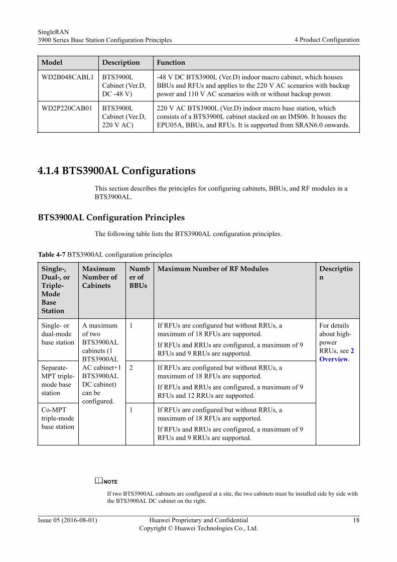
4.1.4 BTS3900AL ConfigurationsThis section describes the principles for configuring cabinets, BBUs, and RF modules in aBTS3900AL.
BTS3900AL Configuration Principles
The following table lists the BTS3900AL configuration principles.
Table 4-7 BTS3900AL configuration principles
Single-,Dual-, orTriple-ModeBaseStation
MaximumNumber ofCabinets
Number ofBBUs
Maximum Number of RF Modules Description
Single- ordual-modebase station
A maximumof twoBTS3900ALcabinets (1BTS3900ALAC cabinet+1BTS3900ALDC cabinet)can beconfigured.
1 If RFUs are configured but without RRUs, amaximum of 18 RFUs are supported.If RFUs and RRUs are configured, a maximum of 9RFUs and 9 RRUs are supported.
For detailsabout high-powerRRUs, see 2Overview.
Separate-MPT triple-mode basestation
2 If RFUs are configured but without RRUs, amaximum of 18 RFUs are supported.If RFUs and RRUs are configured, a maximum of 9RFUs and 12 RRUs are supported.
Co-MPTtriple-modebase station
1 If RFUs are configured but without RRUs, amaximum of 18 RFUs are supported.If RFUs and RRUs are configured, a maximum of 9RFUs and 9 RRUs are supported.
NOTE
If two BTS3900AL cabinets are configured at a site, the two cabinets must be installed side by side withthe BTS3900AL DC cabinet on the right.
SingleRAN3900 Series Base Station Configuration Principles 4 Product Configuration
Issue 05 (2016-08-01) Huawei Proprietary and ConfidentialCopyright © Huawei Technologies Co., Ltd.
18
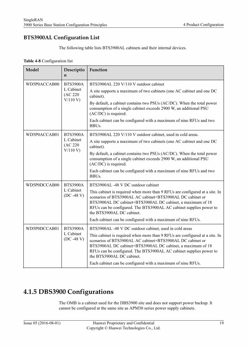
BTS3900AL Configuration List
The following table lists BTS3900AL cabinets and their internal devices.
Table 4-8 Configuration list
Model Description
Function
WD5P0ACCAB00 BTS3900AL Cabinet(AC 220V/110 V)
BTS3900AL 220 V/110 V outdoor cabinetA site supports a maximum of two cabinets (one AC cabinet and one DCcabinet).By default, a cabinet contains two PSUs (AC/DC). When the total powerconsumption of a single cabinet exceeds 2900 W, an additional PSU(AC/DC) is required.Each cabinet can be configured with a maximum of nine RFUs and twoBBUs.
WD5P0ACCAB01 BTS3900AL Cabinet(AC 220V/110 V)
BTS3900AL 220 V/110 V outdoor cabinet, used in cold areas.A site supports a maximum of two cabinets (one AC cabinet and one DCcabinet).By default, a cabinet contains two PSUs (AC/DC). When the total powerconsumption of a single cabinet exceeds 2900 W, an additional PSU(AC/DC) is required.Each cabinet can be configured with a maximum of nine RFUs and twoBBUs.
WD5P0DCCAB00 BTS3900AL Cabinet(DC -48 V)
BTS3900AL -48 V DC outdoor cabinetThis cabinet is required when more than 9 RFUs are configured at a site. Inscenarios of BTS3900AL AC cabinet+BTS3900AL DC cabinet orBTS3900AL DC cabinet+BTS3900AL DC cabinet, a maximum of 18RFUs can be configured. The BTS3900AL AC cabinet supplies power tothe BTS3900AL DC cabinet.Each cabinet can be configured with a maximum of nine RFUs.
WD5P0DCCAB01 BTS3900AL Cabinet(DC -48 V)
BTS3900AL -48 V DC outdoor cabinet, used in cold areasThis cabinet is required when more than 9 RFUs are configured at a site. Inscenarios of BTS3900AL AC cabinet+BTS3900AL DC cabinet orBTS3900AL DC cabinet+BTS3900AL DC cabinet, a maximum of 18RFUs can be configured. The BTS3900AL AC cabinet supplies power tothe BTS3900AL DC cabinet.Each cabinet can be configured with a maximum of nine RFUs.
4.1.5 DBS3900 ConfigurationsThe OMB is a cabinet used for the DBS3900 site and does not support power backup. Itcannot be configured at the same site as APM30 series power supply cabinets.
SingleRAN3900 Series Base Station Configuration Principles 4 Product Configuration
Issue 05 (2016-08-01) Huawei Proprietary and ConfidentialCopyright © Huawei Technologies Co., Ltd.
19
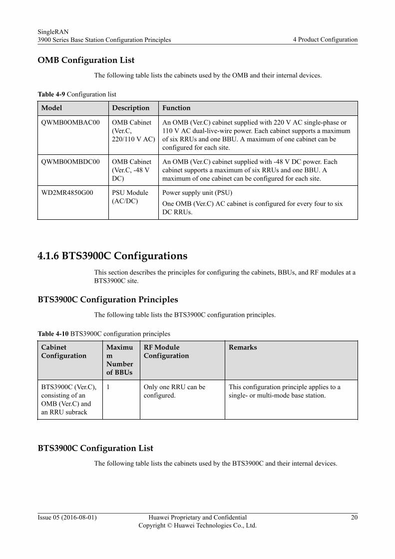
OMB Configuration ListThe following table lists the cabinets used by the OMB and their internal devices.
Table 4-9 Configuration list
Model Description Function
QWMB0OMBAC00 OMB Cabinet(Ver.C,220/110 V AC)
An OMB (Ver.C) cabinet supplied with 220 V AC single-phase or110 V AC dual-live-wire power. Each cabinet supports a maximumof six RRUs and one BBU. A maximum of one cabinet can beconfigured for each site.
QWMB0OMBDC00 OMB Cabinet(Ver.C, -48 VDC)
An OMB (Ver.C) cabinet supplied with -48 V DC power. Eachcabinet supports a maximum of six RRUs and one BBU. Amaximum of one cabinet can be configured for each site.
WD2MR4850G00 PSU Module(AC/DC)
Power supply unit (PSU)One OMB (Ver.C) AC cabinet is configured for every four to sixDC RRUs.
4.1.6 BTS3900C ConfigurationsThis section describes the principles for configuring the cabinets, BBUs, and RF modules at aBTS3900C site.
BTS3900C Configuration PrinciplesThe following table lists the BTS3900C configuration principles.
Table 4-10 BTS3900C configuration principles
CabinetConfiguration
MaximumNumberof BBUs
RF ModuleConfiguration
Remarks
BTS3900C (Ver.C),consisting of anOMB (Ver.C) andan RRU subrack
1 Only one RRU can beconfigured.
This configuration principle applies to asingle- or multi-mode base station.
BTS3900C Configuration ListThe following table lists the cabinets used by the BTS3900C and their internal devices.
SingleRAN3900 Series Base Station Configuration Principles 4 Product Configuration
Issue 05 (2016-08-01) Huawei Proprietary and ConfidentialCopyright © Huawei Technologies Co., Ltd.
20
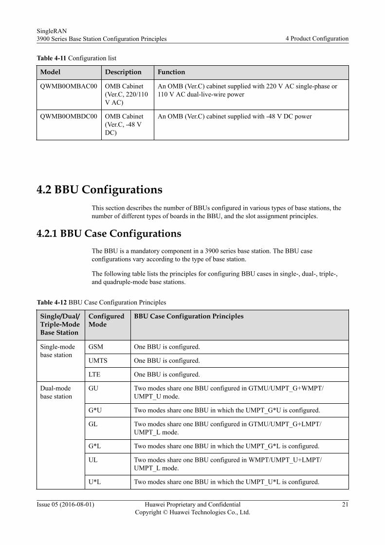
Table 4-11 Configuration list
Model Description Function
QWMB0OMBAC00 OMB Cabinet(Ver.C, 220/110V AC)
An OMB (Ver.C) cabinet supplied with 220 V AC single-phase or110 V AC dual-live-wire power
QWMB0OMBDC00 OMB Cabinet(Ver.C, -48 VDC)
An OMB (Ver.C) cabinet supplied with -48 V DC power
4.2 BBU ConfigurationsThis section describes the number of BBUs configured in various types of base stations, thenumber of different types of boards in the BBU, and the slot assignment principles.
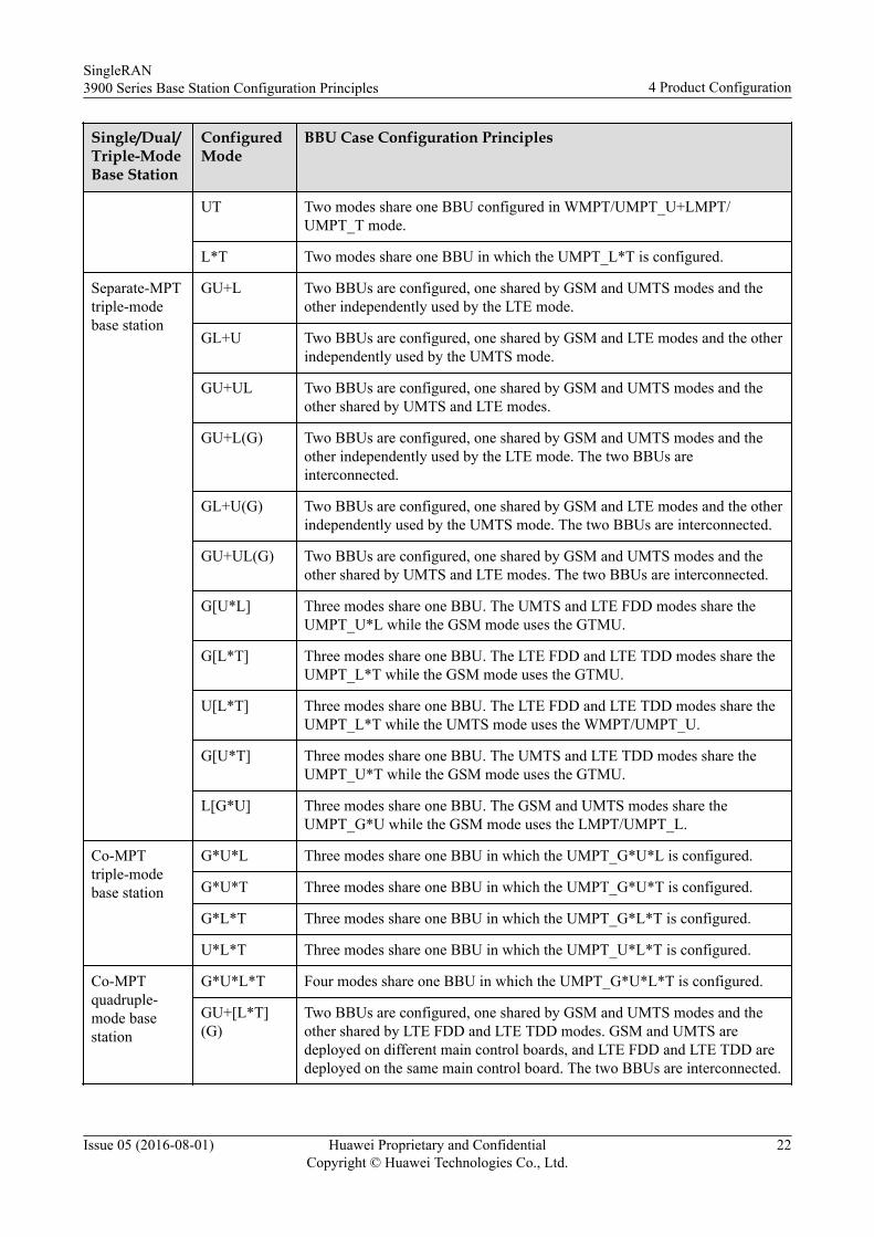
4.2.1 BBU Case ConfigurationsThe BBU is a mandatory component in a 3900 series base station. The BBU caseconfigurations vary according to the type of base station.
The following table lists the principles for configuring BBU cases in single-, dual-, triple-,and quadruple-mode base stations.
Table 4-12 BBU Case Configuration Principles
Single/Dual/Triple-ModeBase Station
ConfiguredMode
BBU Case Configuration Principles
Single-modebase station
GSM One BBU is configured.
UMTS One BBU is configured.
LTE One BBU is configured.
Dual-modebase station
GU Two modes share one BBU configured in GTMU/UMPT_G+WMPT/UMPT_U mode.
G*U Two modes share one BBU in which the UMPT_G*U is configured.
GL Two modes share one BBU configured in GTMU/UMPT_G+LMPT/UMPT_L mode.
G*L Two modes share one BBU in which the UMPT_G*L is configured.
UL Two modes share one BBU configured in WMPT/UMPT_U+LMPT/UMPT_L mode.
U*L Two modes share one BBU in which the UMPT_U*L is configured.
SingleRAN3900 Series Base Station Configuration Principles 4 Product Configuration
Issue 05 (2016-08-01) Huawei Proprietary and ConfidentialCopyright © Huawei Technologies Co., Ltd.
21
Single/Dual/Triple-ModeBase Station
ConfiguredMode
BBU Case Configuration Principles
UT Two modes share one BBU configured in WMPT/UMPT_U+LMPT/UMPT_T mode.
L*T Two modes share one BBU in which the UMPT_L*T is configured.
Separate-MPTtriple-modebase station
GU+L Two BBUs are configured, one shared by GSM and UMTS modes and theother independently used by the LTE mode.
GL+U Two BBUs are configured, one shared by GSM and LTE modes and the otherindependently used by the UMTS mode.
GU+UL Two BBUs are configured, one shared by GSM and UMTS modes and theother shared by UMTS and LTE modes.
GU+L(G) Two BBUs are configured, one shared by GSM and UMTS modes and theother independently used by the LTE mode. The two BBUs areinterconnected.
GL+U(G) Two BBUs are configured, one shared by GSM and LTE modes and the otherindependently used by the UMTS mode. The two BBUs are interconnected.
GU+UL(G) Two BBUs are configured, one shared by GSM and UMTS modes and theother shared by UMTS and LTE modes. The two BBUs are interconnected.
G[U*L] Three modes share one BBU. The UMTS and LTE FDD modes share theUMPT_U*L while the GSM mode uses the GTMU.
G[L*T] Three modes share one BBU. The LTE FDD and LTE TDD modes share theUMPT_L*T while the GSM mode uses the GTMU.
U[L*T] Three modes share one BBU. The LTE FDD and LTE TDD modes share theUMPT_L*T while the UMTS mode uses the WMPT/UMPT_U.
G[U*T] Three modes share one BBU. The UMTS and LTE TDD modes share theUMPT_U*T while the GSM mode uses the GTMU.
L[G*U] Three modes share one BBU. The GSM and UMTS modes share theUMPT_G*U while the GSM mode uses the LMPT/UMPT_L.
Co-MPTtriple-modebase station
G*U*L Three modes share one BBU in which the UMPT_G*U*L is configured.
G*U*T Three modes share one BBU in which the UMPT_G*U*T is configured.
G*L*T Three modes share one BBU in which the UMPT_G*L*T is configured.
U*L*T Three modes share one BBU in which the UMPT_U*L*T is configured.
Co-MPTquadruple-mode basestation
G*U*L*T Four modes share one BBU in which the UMPT_G*U*L*T is configured.
GU+[L*T](G)
Two BBUs are configured, one shared by GSM and UMTS modes and theother shared by LTE FDD and LTE TDD modes. GSM and UMTS aredeployed on different main control boards, and LTE FDD and LTE TDD aredeployed on the same main control board. The two BBUs are interconnected.
SingleRAN3900 Series Base Station Configuration Principles 4 Product Configuration
Issue 05 (2016-08-01) Huawei Proprietary and ConfidentialCopyright © Huawei Technologies Co., Ltd.
22
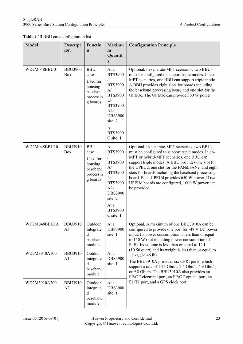
Table 4-13 BBU case configuration list
Model Description
Function
MaximumQuantity
Configuration Principle
WD2M048BBU01 BBU3900Box
BBUcaseUsed forhousingbasebandprocessing boards
At aBTS3900/BTS3900A/BTS3900L/BTS3900AL/DBS3900site: 2At aBTS3900C site: 1
Optional. In separate-MPT scenarios, two BBUsmust be configured to support triple modes. In co-MPT scenarios, one BBU can support triple modes.A BBU provides eight slots for boards includingthe baseband processing board and one slot for theUPEUc. The UPEUc can provide 360 W power.
WD2M048BBU10 BBU3910Box
BBUcaseUsed forhousingbasebandprocessing boards
At aBTS3900/BTS3900A/BTS3900L/BTS3900AL/DBS3900site: 2At aBTS3900C site: 1
Optional. In separate-MPT scenarios, two BBUsmust be configured to support triple modes. In co-MPT or hybrid-MPT scenarios, one BBU cansupport triple modes. A BBU provides one slot forthe UPEUd, one slot for the FANd/FANe, and eightslots for boards including the baseband processingboard. Each UPEUd provides 650 W power. If twoUPEUd boards are configured, 1000 W power canbe provided.
WD2M048BBU1A BBU3910A3
Outdoorintegratedbasebandmodule
At aDBS3900site: 1
Optional. A maximum of one BBU3910A can beconfigured to provide one port for -48 V DC powerinput. Its power consumption is less than or equalto 150 W (not including power consumption ofPoE). Its volume is less than or equal to 12 L(10.56 quart) and its weight is less than or equal to12 kg (26.46 lb).The BBU3910A provides six CPRI ports, whichsupport a rate of 1.25 Gbit/s, 2.5 Gbit/s, 4.9 Gbit/s,or 9.8 Gbit/s. The BBU3910A also provides anFE/GE electrical port, an FE/GE optical port, anE1/T1 port, and a GPS clock port.
WD2M3910A100 BBU3910A1
Outdoorintegratedbasebandmodule
At aDBS3900site: 1
WD2M3910A200 BBU3910A2
Outdoorintegratedbasebandmodule
At aDBS3900site: 1
SingleRAN3900 Series Base Station Configuration Principles 4 Product Configuration
Issue 05 (2016-08-01) Huawei Proprietary and ConfidentialCopyright © Huawei Technologies Co., Ltd.
23
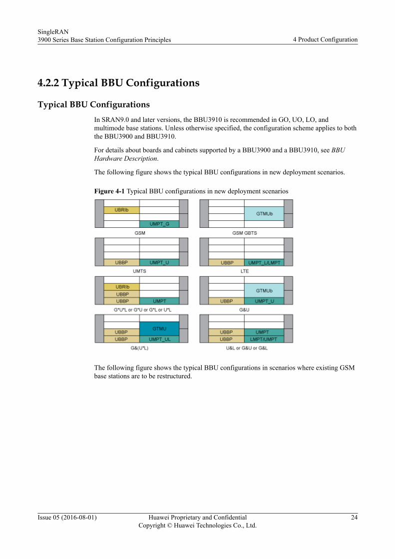
4.2.2 Typical BBU Configurations
Typical BBU ConfigurationsIn SRAN9.0 and later versions, the BBU3910 is recommended in GO, UO, LO, andmultimode base stations. Unless otherwise specified, the configuration scheme applies to boththe BBU3900 and BBU3910.
For details about boards and cabinets supported by a BBU3900 and a BBU3910, see BBUHardware Description.
The following figure shows the typical BBU configurations in new deployment scenarios.
Figure 4-1 Typical BBU configurations in new deployment scenarios
The following figure shows the typical BBU configurations in scenarios where existing GSMbase stations are to be restructured.
SingleRAN3900 Series Base Station Configuration Principles 4 Product Configuration
Issue 05 (2016-08-01) Huawei Proprietary and ConfidentialCopyright © Huawei Technologies Co., Ltd.
24
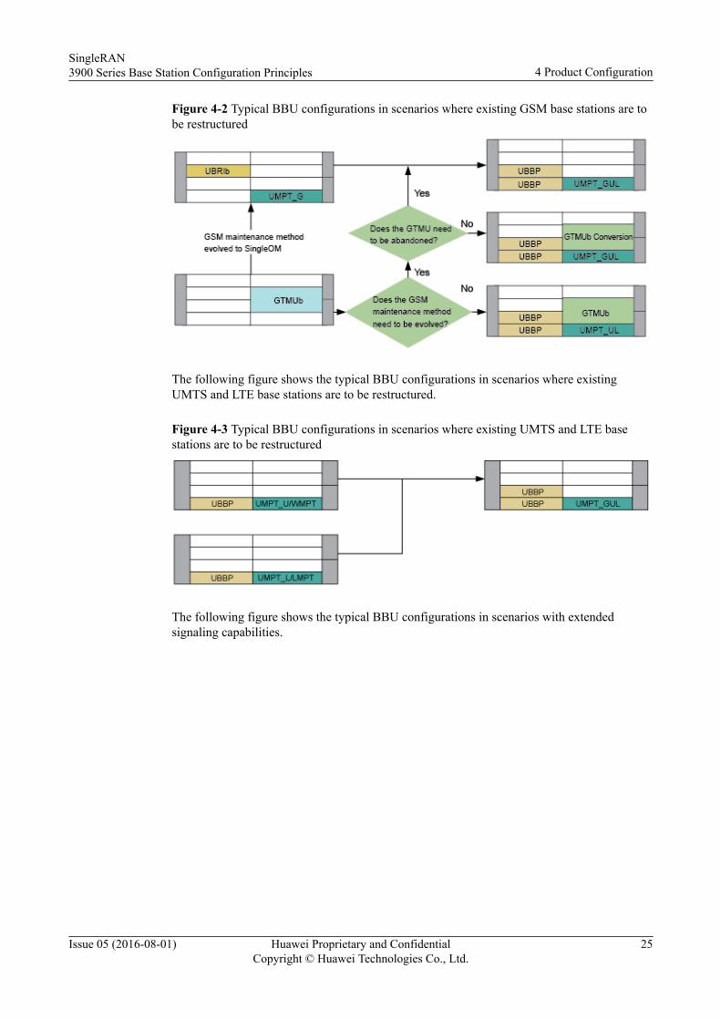
Figure 4-2 Typical BBU configurations in scenarios where existing GSM base stations are tobe restructured
The following figure shows the typical BBU configurations in scenarios where existingUMTS and LTE base stations are to be restructured.
Figure 4-3 Typical BBU configurations in scenarios where existing UMTS and LTE basestations are to be restructured
The following figure shows the typical BBU configurations in scenarios with extendedsignaling capabilities.
SingleRAN3900 Series Base Station Configuration Principles 4 Product Configuration
Issue 05 (2016-08-01) Huawei Proprietary and ConfidentialCopyright © Huawei Technologies Co., Ltd.
25
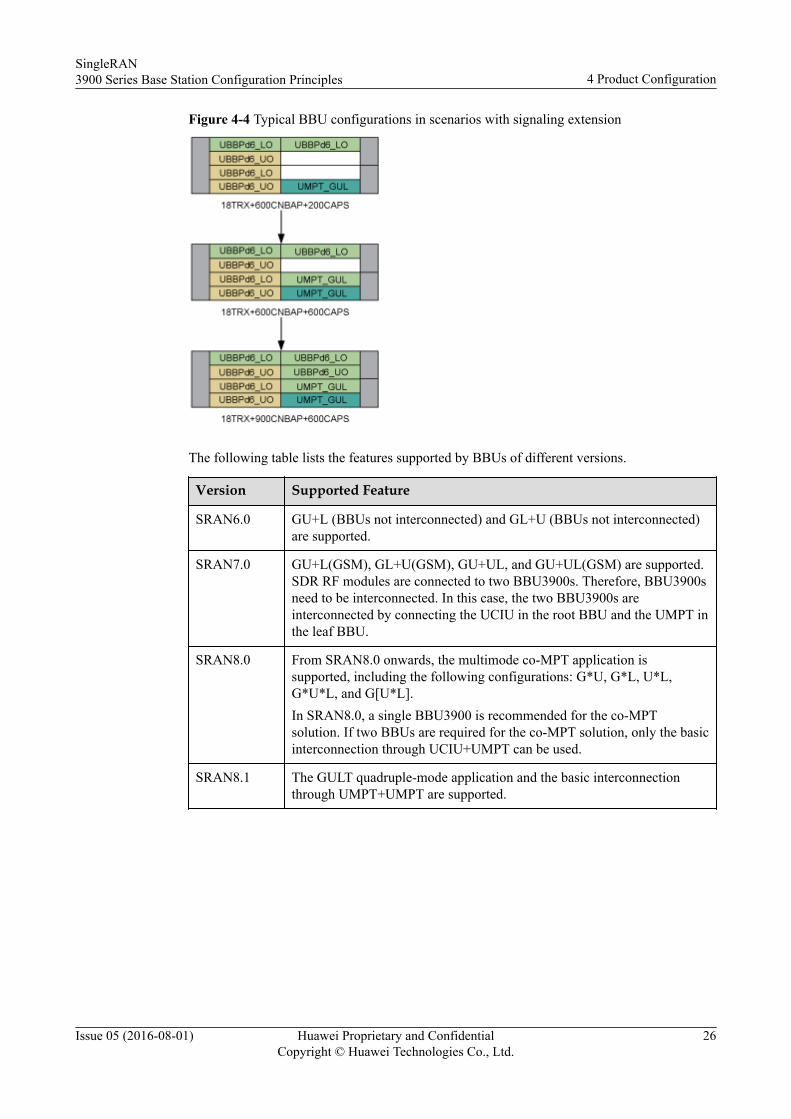
Figure 4-4 Typical BBU configurations in scenarios with signaling extension
The following table lists the features supported by BBUs of different versions.
Version Supported Feature
SRAN6.0 GU+L (BBUs not interconnected) and GL+U (BBUs not interconnected)are supported.
SRAN7.0 GU+L(GSM), GL+U(GSM), GU+UL, and GU+UL(GSM) are supported.SDR RF modules are connected to two BBU3900s. Therefore, BBU3900sneed to be interconnected. In this case, the two BBU3900s areinterconnected by connecting the UCIU in the root BBU and the UMPT inthe leaf BBU.
SRAN8.0 From SRAN8.0 onwards, the multimode co-MPT application issupported, including the following configurations: G*U, G*L, U*L,G*U*L, and G[U*L].In SRAN8.0, a single BBU3900 is recommended for the co-MPTsolution. If two BBUs are required for the co-MPT solution, only the basicinterconnection through UCIU+UMPT can be used.
SRAN8.1 The GULT quadruple-mode application and the basic interconnectionthrough UMPT+UMPT are supported.
SingleRAN3900 Series Base Station Configuration Principles 4 Product Configuration
Issue 05 (2016-08-01) Huawei Proprietary and ConfidentialCopyright © Huawei Technologies Co., Ltd.
26
Version Supported Feature
SRAN9.0 l The BBU3910 (with a fully-interconnected backplane) is supportedand it supports enhanced board interconnection technologies.
l Co-MPT and hybrid-MPT dual-BBU base stations support applicationssuch as [G*U*L]+[G*U*L] and G[U*L]+[U*L]. If each BBU isconfigured with a UMPT, the UMPT+UMPT interconnection mode isrecommended as an alternative for the UCIU+UMPT interconnectionmode, which is supported since SRAN7.0.
l The GUL co-BBP technique is supported, which means that multiplemodes including GSM, UMTS, and LTE can be concurrentlyconfigured on one baseband processing board. The co-BBP techniqueis supported only by co-MPT base stations, not by separate-MPT basestations.
SRAN10.0 The BBU3910A3 is supported, which can work in GSM only, UMTSonly, or LTE only mode and the three modes can be reconfigured to oneanother. In addition, the BBU3910A3 can work in GU/GL/UL/GUL co-MPT and co-BBP modes.
SRAN10.1 l LTE FDD and LTE TDD co-MPT is supported.l The BBU3910A1 and BBU3910A2 are supported, which can work in
GSM only, UMTS only, or LTE only mode and the three modes can bereconfigured to one another. In addition, the BBU3910A1 andBBU3910A2 can work in GU/GL/UL co-MPT mode.
NOTEIn SRAN10.0 and SRAN10.1, a BBU3910A cannot be interconnected with aBBU3900, BBU3910, or BBU3910A.
SRAN11.0 The GTMUc is supported.
SRAN11.1 The multimode co-MPT board UMPTe and multimode co-BBP boardUBBPe are supported.
CPRI Networking ConfigurationsThe slot constraints and limitations in CPRI networking configuration apply only to theBBU3900.
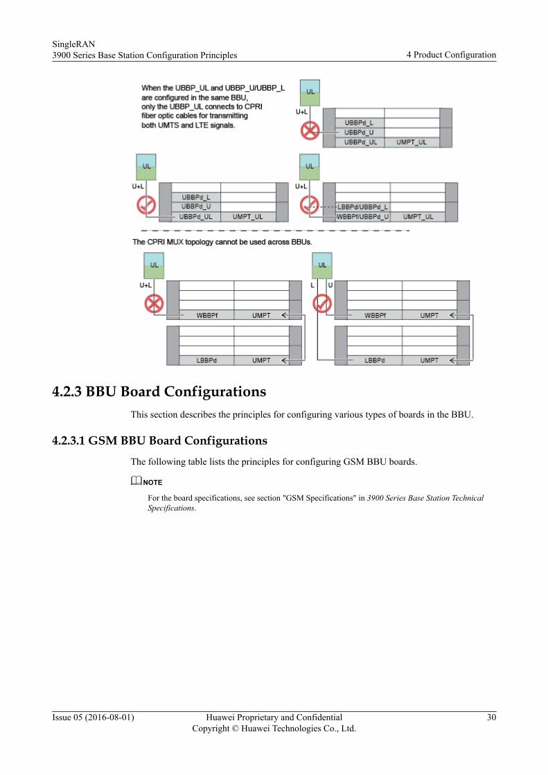
CPRI networking configurations in separate-MPT scenarios
In separate-MPT scenarios where multimode SDR RF modules are used, the dual-star CPRInetworking topology is recommended. In this networking topology, a CPRI fiber optic cablefrom the baseband processing board of each mode is connected to its corresponding RFmodules.
SingleRAN3900 Series Base Station Configuration Principles 4 Product Configuration
Issue 05 (2016-08-01) Huawei Proprietary and ConfidentialCopyright © Huawei Technologies Co., Ltd.
27
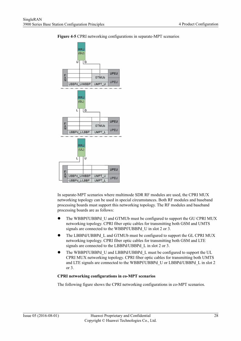
Figure 4-5 CPRI networking configurations in separate-MPT scenarios
In separate-MPT scenarios where multimode SDR RF modules are used, the CPRI MUXnetworking topology can be used in special circumstances. Both RF modules and basebandprocessing boards must support this networking topology. The RF modules and basebandprocessing boards are as follows:
l The WBBPf/UBBPd_U and GTMUb must be configured to support the GU CPRI MUXnetworking topology. CPRI fiber optic cables for transmitting both GSM and UMTSsignals are connected to the WBBPf/UBBPd_U in slot 2 or 3.
l The LBBPd/UBBPd_L and GTMUb must be configured to support the GL CPRI MUXnetworking topology. CPRI fiber optic cables for transmitting both GSM and LTEsignals are connected to the LBBPd/UBBPd_L in slot 2 or 3.
l The WBBPf/UBBPd_U and LBBPd/UBBPd_L must be configured to support the ULCPRI MUX networking topology. CPRI fiber optic cables for transmitting both UMTSand LTE signals are connected to the WBBPf/UBBPd_U or LBBPd/UBBPd_L in slot 2or 3.
CPRI networking configurations in co-MPT scenarios
The following figure shows the CPRI networking configurations in co-MPT scenarios.
SingleRAN3900 Series Base Station Configuration Principles 4 Product Configuration
Issue 05 (2016-08-01) Huawei Proprietary and ConfidentialCopyright © Huawei Technologies Co., Ltd.
28
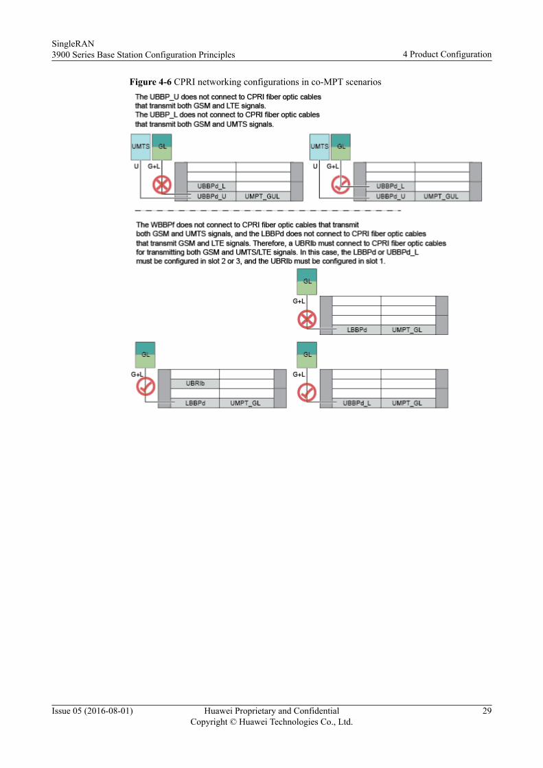
Figure 4-6 CPRI networking configurations in co-MPT scenarios
SingleRAN3900 Series Base Station Configuration Principles 4 Product Configuration
Issue 05 (2016-08-01) Huawei Proprietary and ConfidentialCopyright © Huawei Technologies Co., Ltd.
29
4.2.3 BBU Board ConfigurationsThis section describes the principles for configuring various types of boards in the BBU.
4.2.3.1 GSM BBU Board ConfigurationsThe following table lists the principles for configuring GSM BBU boards.
NOTE
For the board specifications, see section "GSM Specifications" in 3900 Series Base Station TechnicalSpecifications.
SingleRAN3900 Series Base Station Configuration Principles 4 Product Configuration
Issue 05 (2016-08-01) Huawei Proprietary and ConfidentialCopyright © Huawei Technologies Co., Ltd.
30
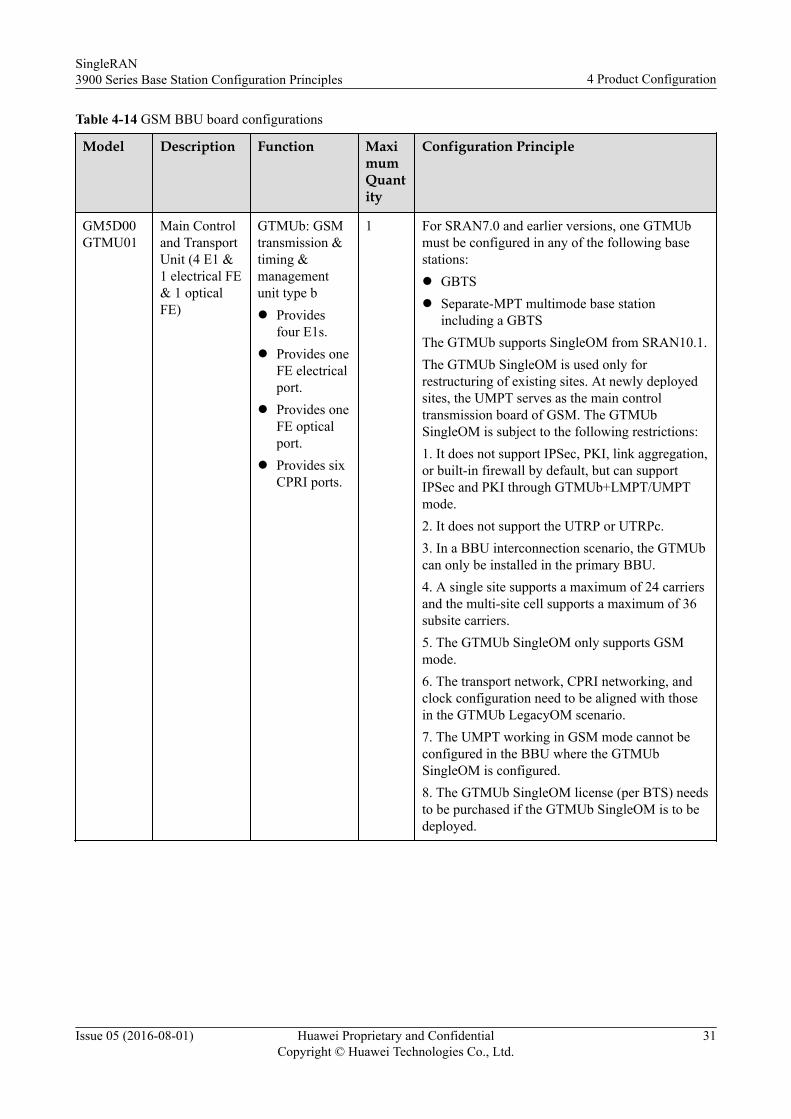
Table 4-14 GSM BBU board configurations
Model Description Function MaximumQuantity
Configuration Principle
GM5D00GTMU01
Main Controland TransportUnit (4 E1 &1 electrical FE& 1 opticalFE)
GTMUb: GSMtransmission &timing &managementunit type bl Provides
four E1s.l Provides one
FE electricalport.
l Provides oneFE opticalport.
l Provides sixCPRI ports.
1 For SRAN7.0 and earlier versions, one GTMUbmust be configured in any of the following basestations:l GBTSl Separate-MPT multimode base station
including a GBTSThe GTMUb supports SingleOM from SRAN10.1.The GTMUb SingleOM is used only forrestructuring of existing sites. At newly deployedsites, the UMPT serves as the main controltransmission board of GSM. The GTMUbSingleOM is subject to the following restrictions:1. It does not support IPSec, PKI, link aggregation,or built-in firewall by default, but can supportIPSec and PKI through GTMUb+LMPT/UMPTmode.2. It does not support the UTRP or UTRPc.3. In a BBU interconnection scenario, the GTMUbcan only be installed in the primary BBU.4. A single site supports a maximum of 24 carriersand the multi-site cell supports a maximum of 36subsite carriers.5. The GTMUb SingleOM only supports GSMmode.6. The transport network, CPRI networking, andclock configuration need to be aligned with thosein the GTMUb LegacyOM scenario.7. The UMPT working in GSM mode cannot beconfigured in the BBU where the GTMUbSingleOM is configured.8. The GTMUb SingleOM license (per BTS) needsto be purchased if the GTMUb SingleOM is to bedeployed.
SingleRAN3900 Series Base Station Configuration Principles 4 Product Configuration
Issue 05 (2016-08-01) Huawei Proprietary and ConfidentialCopyright © Huawei Technologies Co., Ltd.
31
Model Description Function MaximumQuantity
Configuration Principle
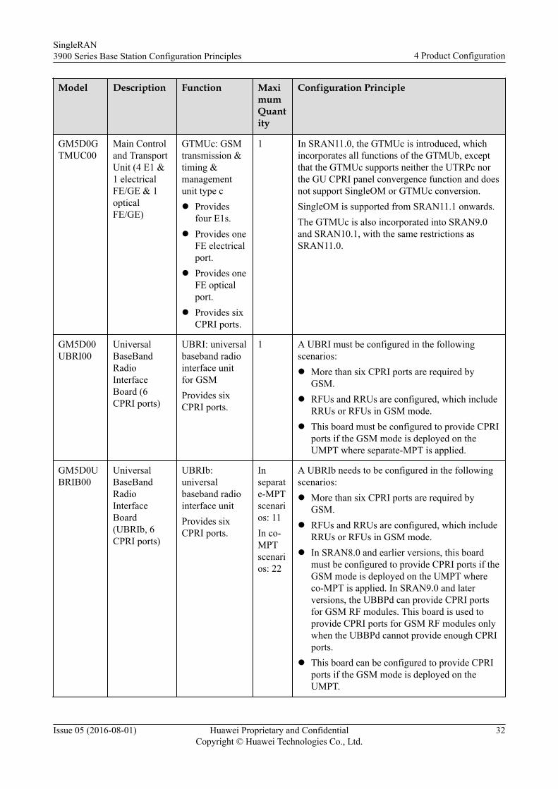
GM5D0GTMUC00
Main Controland TransportUnit (4 E1 &1 electricalFE/GE & 1opticalFE/GE)
GTMUc: GSMtransmission &timing &managementunit type cl Provides
four E1s.l Provides one
FE electricalport.
l Provides oneFE opticalport.
l Provides sixCPRI ports.
1 In SRAN11.0, the GTMUc is introduced, whichincorporates all functions of the GTMUb, exceptthat the GTMUc supports neither the UTRPc northe GU CPRI panel convergence function and doesnot support SingleOM or GTMUc conversion.SingleOM is supported from SRAN11.1 onwards.The GTMUc is also incorporated into SRAN9.0and SRAN10.1, with the same restrictions asSRAN11.0.
GM5D00UBRI00
UniversalBaseBandRadioInterfaceBoard (6CPRI ports)
UBRI: universalbaseband radiointerface unitfor GSMProvides sixCPRI ports.
1 A UBRI must be configured in the followingscenarios:l More than six CPRI ports are required by
GSM.l RFUs and RRUs are configured, which include
RRUs or RFUs in GSM mode.l This board must be configured to provide CPRI
ports if the GSM mode is deployed on theUMPT where separate-MPT is applied.
GM5D0UBRIB00
UniversalBaseBandRadioInterfaceBoard(UBRIb, 6CPRI ports)
UBRIb:universalbaseband radiointerface unitProvides sixCPRI ports.
Inseparate-MPTscenarios: 11In co-MPTscenarios: 22
A UBRIb needs to be configured in the followingscenarios:l More than six CPRI ports are required by
GSM.l RFUs and RRUs are configured, which include
RRUs or RFUs in GSM mode.l In SRAN8.0 and earlier versions, this board
must be configured to provide CPRI ports if theGSM mode is deployed on the UMPT whereco-MPT is applied. In SRAN9.0 and laterversions, the UBBPd can provide CPRI portsfor GSM RF modules. This board is used toprovide CPRI ports for GSM RF modules onlywhen the UBBPd cannot provide enough CPRIports.
l This board can be configured to provide CPRIports if the GSM mode is deployed on theUMPT.
SingleRAN3900 Series Base Station Configuration Principles 4 Product Configuration
Issue 05 (2016-08-01) Huawei Proprietary and ConfidentialCopyright © Huawei Technologies Co., Ltd.
32
4.2.3.2 UMTS BBU Board ConfigurationsNOTE
For specifications of BBU boards, see UMTS Specifications in 3900 Series Base Station TechnicalDescription.
The following table lists the UMTS BBU board configurations.
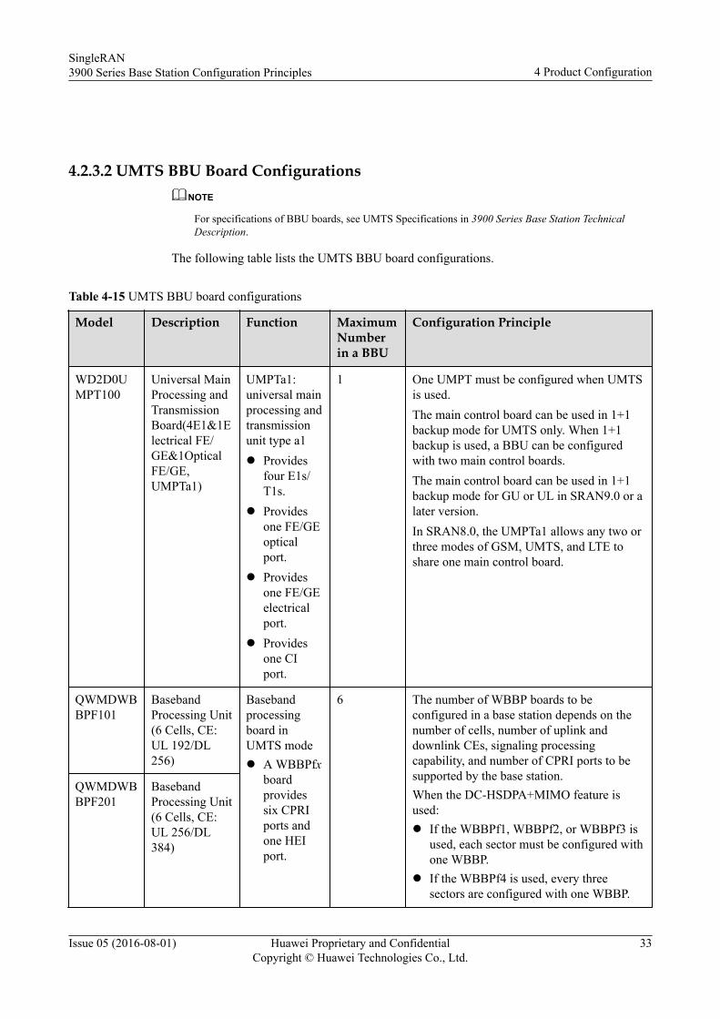
Table 4-15 UMTS BBU board configurations
Model Description Function MaximumNumberin a BBU
Configuration Principle
WD2D0UMPT100
Universal MainProcessing andTransmissionBoard(4E1&1Electrical FE/GE&1OpticalFE/GE,UMPTa1)
UMPTa1:universal mainprocessing andtransmissionunit type a1l Provides
four E1s/T1s.
l Providesone FE/GEopticalport.
l Providesone FE/GEelectricalport.
l Providesone CIport.
1 One UMPT must be configured when UMTSis used.The main control board can be used in 1+1backup mode for UMTS only. When 1+1backup is used, a BBU can be configuredwith two main control boards.The main control board can be used in 1+1backup mode for GU or UL in SRAN9.0 or alater version.In SRAN8.0, the UMPTa1 allows any two orthree modes of GSM, UMTS, and LTE toshare one main control board.
QWMDWBBPF101
BasebandProcessing Unit(6 Cells, CE:UL 192/DL256)
Basebandprocessingboard inUMTS model A WBBPfx
boardprovidessix CPRIports andone HEIport.
6 The number of WBBP boards to beconfigured in a base station depends on thenumber of cells, number of uplink anddownlink CEs, signaling processingcapability, and number of CPRI ports to besupported by the base station.When the DC-HSDPA+MIMO feature isused:l If the WBBPf1, WBBPf2, or WBBPf3 is
used, each sector must be configured withone WBBP.
l If the WBBPf4 is used, every threesectors are configured with one WBBP.
QWMDWBBPF201
BasebandProcessing Unit(6 Cells, CE:UL 256/DL384)
SingleRAN3900 Series Base Station Configuration Principles 4 Product Configuration
Issue 05 (2016-08-01) Huawei Proprietary and ConfidentialCopyright © Huawei Technologies Co., Ltd.
33
Model Description Function MaximumNumberin a BBU
Configuration Principle
QWMDWBBPF301
BasebandProcessing Unit(6 Cells, CE:UL 384/DL512)
The WBBPf board is recommended fromRAN14.0 onwards.To support DC-HSDPA+MIMO, each sectormust be configured with one WBBPf1,WBBPf2, or WBBPf3.The WBBPf4 supports DC-HSDPA+MIMOfor three sectors.When Independent Demodulation of Signalsfrom Multiple RRUs in One Cell is enabled,the WBBPf supports a maximum of sixRRUs (with two transmit channels each) inone cell.
QWMDWBBPF400
BasebandProcessing Unit(6 Cells, CE:UL 512/DL768)
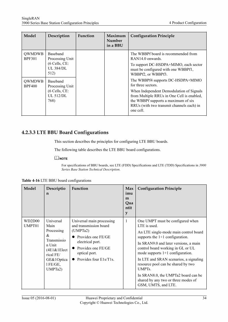
4.2.3.3 LTE BBU Board Configurations
This section describes the principles for configuring LTE BBU boards.
The following table describes the LTE BBU board configurations.
NOTE
For specifications of BBU boards, see LTE (FDD) Specifications and LTE (TDD) Specifications in 3900Series Base Station Technical Description.
Table 4-16 LTE BBU board configurations
Model Description
Function MaximumQuantity
Configuration Principle
WD2D00UMPT01
UniversalMainProcessing&Transmission Unit(4E1&1Electrical FE/GE&1Optical FE/GE,UMPTa2)
Universal main processingand transmission board(UMPTa2)l Provides one FE/GE
electrical port.l Provides one FE/GE
optical port.l Provides four E1s/T1s.
1 One UMPT must be configured whenLTE is used.An LTE single-mode main control boardsupports the 1+1 configuration.In SRAN9.0 and later versions, a maincontrol board working in GL or ULmode supports 1+1 configuration.In LTE and SRAN scenarios, a signalingresource pool can be shared by twoUMPTs.In SRAN8.0, the UMPTa2 board can beshared by any two or three modes ofGSM, UMTS, and LTE.
SingleRAN3900 Series Base Station Configuration Principles 4 Product Configuration
Issue 05 (2016-08-01) Huawei Proprietary and ConfidentialCopyright © Huawei Technologies Co., Ltd.
34
Model Description
Function MaximumQuantity
Configuration Principle
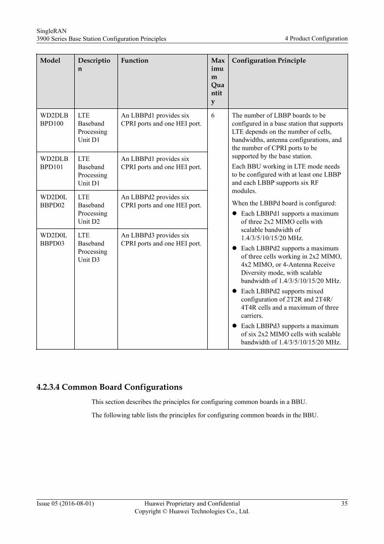
WD2DLBBPD100
LTEBasebandProcessingUnit D1
An LBBPd1 provides sixCPRI ports and one HEI port.
6 The number of LBBP boards to beconfigured in a base station that supportsLTE depends on the number of cells,bandwidths, antenna configurations, andthe number of CPRI ports to besupported by the base station.Each BBU working in LTE mode needsto be configured with at least one LBBPand each LBBP supports six RFmodules.
When the LBBPd board is configured:l Each LBBPd1 supports a maximum
of three 2x2 MIMO cells withscalable bandwidth of1.4/3/5/10/15/20 MHz.
l Each LBBPd2 supports a maximumof three cells working in 2x2 MIMO,4x2 MIMO, or 4-Antenna ReceiveDiversity mode, with scalablebandwidth of 1.4/3/5/10/15/20 MHz.
l Each LBBPd2 supports mixedconfiguration of 2T2R and 2T4R/4T4R cells and a maximum of threecarriers.
l Each LBBPd3 supports a maximumof six 2x2 MIMO cells with scalablebandwidth of 1.4/3/5/10/15/20 MHz.
WD2DLBBPD101
LTEBasebandProcessingUnit D1
An LBBPd1 provides sixCPRI ports and one HEI port.
WD2D0LBBPD02
LTEBasebandProcessingUnit D2
An LBBPd2 provides sixCPRI ports and one HEI port.
WD2D0LBBPD03
LTEBasebandProcessingUnit D3
An LBBPd3 provides sixCPRI ports and one HEI port.
4.2.3.4 Common Board ConfigurationsThis section describes the principles for configuring common boards in a BBU.
The following table lists the principles for configuring common boards in the BBU.
SingleRAN3900 Series Base Station Configuration Principles 4 Product Configuration
Issue 05 (2016-08-01) Huawei Proprietary and ConfidentialCopyright © Huawei Technologies Co., Ltd.
35
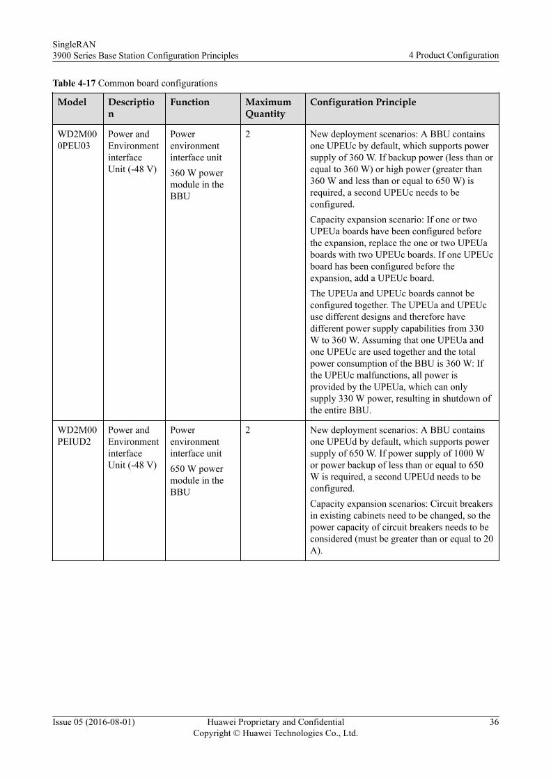
Table 4-17 Common board configurations
Model Description
Function MaximumQuantity
Configuration Principle
WD2M000PEU03
Power andEnvironmentinterfaceUnit (-48 V)
Powerenvironmentinterface unit360 W powermodule in theBBU
2 New deployment scenarios: A BBU containsone UPEUc by default, which supports powersupply of 360 W. If backup power (less than orequal to 360 W) or high power (greater than360 W and less than or equal to 650 W) isrequired, a second UPEUc needs to beconfigured.Capacity expansion scenario: If one or twoUPEUa boards have been configured beforethe expansion, replace the one or two UPEUaboards with two UPEUc boards. If one UPEUcboard has been configured before theexpansion, add a UPEUc board.The UPEUa and UPEUc boards cannot beconfigured together. The UPEUa and UPEUcuse different designs and therefore havedifferent power supply capabilities from 330W to 360 W. Assuming that one UPEUa andone UPEUc are used together and the totalpower consumption of the BBU is 360 W: Ifthe UPEUc malfunctions, all power isprovided by the UPEUa, which can onlysupply 330 W power, resulting in shutdown ofthe entire BBU.
WD2M00PEIUD2
Power andEnvironmentinterfaceUnit (-48 V)
Powerenvironmentinterface unit650 W powermodule in theBBU
2 New deployment scenarios: A BBU containsone UPEUd by default, which supports powersupply of 650 W. If power supply of 1000 Wor power backup of less than or equal to 650W is required, a second UPEUd needs to beconfigured.Capacity expansion scenarios: Circuit breakersin existing cabinets need to be changed, so thepower capacity of circuit breakers needs to beconsidered (must be greater than or equal to 20A).
SingleRAN3900 Series Base Station Configuration Principles 4 Product Configuration
Issue 05 (2016-08-01) Huawei Proprietary and ConfidentialCopyright © Huawei Technologies Co., Ltd.
36
Model Description
Function MaximumQuantity
Configuration Principle
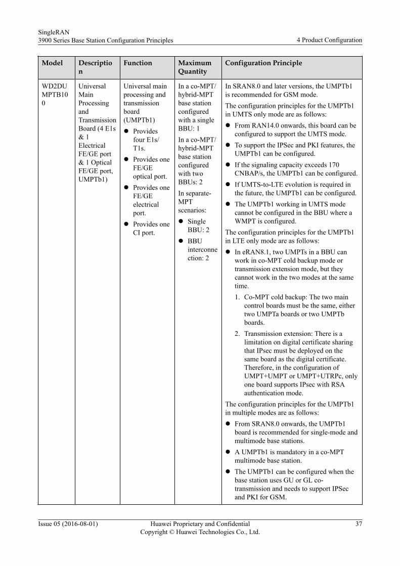
WD2DUMPTB100
UniversalMainProcessingandTransmissionBoard (4 E1s& 1ElectricalFE/GE port& 1 OpticalFE/GE port,UMPTb1)
Universal mainprocessing andtransmissionboard(UMPTb1)l Provides
four E1s/T1s.
l Provides oneFE/GEoptical port.
l Provides oneFE/GEelectricalport.
l Provides oneCI port.
In a co-MPT/hybrid-MPTbase stationconfiguredwith a singleBBU: 1In a co-MPT/hybrid-MPTbase stationconfiguredwith twoBBUs: 2In separate-MPTscenarios:l Single
BBU: 2l BBU
interconnection: 2
In SRAN8.0 and later versions, the UMPTb1is recommended for GSM mode.The configuration principles for the UMPTb1in UMTS only mode are as follows:l From RAN14.0 onwards, this board can be
configured to support the UMTS mode.l To support the IPSec and PKI features, the
UMPTb1 can be configured.l If the signaling capacity exceeds 170
CNBAP/s, the UMPTb1 can be configured.l If UMTS-to-LTE evolution is required in
the future, the UMPTb1 can be configured.l The UMPTb1 working in UMTS mode
cannot be configured in the BBU where aWMPT is configured.
The configuration principles for the UMPTb1in LTE only mode are as follows:l In eRAN8.1, two UMPTs in a BBU can
work in co-MPT cold backup mode ortransmission extension mode, but theycannot work in the two modes at the sametime.1. Co-MPT cold backup: The two main
control boards must be the same, eithertwo UMPTa boards or two UMPTbboards.
2. Transmission extension: There is alimitation on digital certificate sharingthat IPsec must be deployed on thesame board as the digital certificate.Therefore, in the configuration ofUMPT+UMPT or UMPT+UTRPc, onlyone board supports IPsec with RSAauthentication mode.
The configuration principles for the UMPTb1in multiple modes are as follows:l From SRAN8.0 onwards, the UMPTb1
board is recommended for single-mode andmultimode base stations.
l A UMPTb1 is mandatory in a co-MPTmultimode base station.
l The UMPTb1 can be configured when thebase station uses GU or GL co-transmission and needs to support IPSecand PKI for GSM.
SingleRAN3900 Series Base Station Configuration Principles 4 Product Configuration
Issue 05 (2016-08-01) Huawei Proprietary and ConfidentialCopyright © Huawei Technologies Co., Ltd.
37
Model Description
Function MaximumQuantity
Configuration Principle
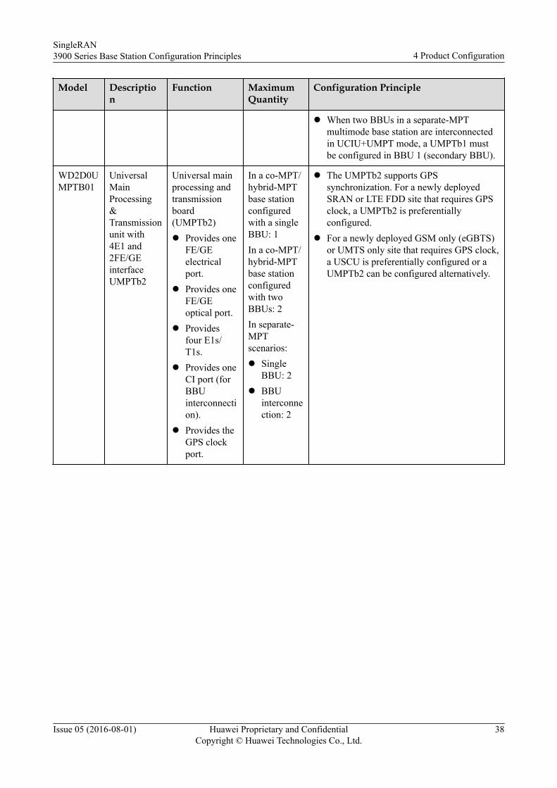
l When two BBUs in a separate-MPTmultimode base station are interconnectedin UCIU+UMPT mode, a UMPTb1 mustbe configured in BBU 1 (secondary BBU).
WD2D0UMPTB01
UniversalMainProcessing&Transmissionunit with4E1 and2FE/GEinterfaceUMPTb2
Universal mainprocessing andtransmissionboard(UMPTb2)l Provides one
FE/GEelectricalport.
l Provides oneFE/GEoptical port.
l Providesfour E1s/T1s.
l Provides oneCI port (forBBUinterconnection).
l Provides theGPS clockport.
In a co-MPT/hybrid-MPTbase stationconfiguredwith a singleBBU: 1In a co-MPT/hybrid-MPTbase stationconfiguredwith twoBBUs: 2In separate-MPTscenarios:l Single
BBU: 2l BBU
interconnection: 2
l The UMPTb2 supports GPSsynchronization. For a newly deployedSRAN or LTE FDD site that requires GPSclock, a UMPTb2 is preferentiallyconfigured.
l For a newly deployed GSM only (eGBTS)or UMTS only site that requires GPS clock,a USCU is preferentially configured or aUMPTb2 can be configured alternatively.
SingleRAN3900 Series Base Station Configuration Principles 4 Product Configuration
Issue 05 (2016-08-01) Huawei Proprietary and ConfidentialCopyright © Huawei Technologies Co., Ltd.
38
Model Description
Function MaximumQuantity
Configuration Principle
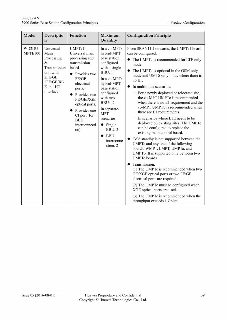
WD2DUMPTE100
UniversalMainProcessing&Transmissionunit with2FE/GE2FE/GE/XGE and 1CIinterface
UMPTe1:Universal mainprocessing andtransmissionboardl Provides two
FE/GEelectricalports.
l Provides twoFE/GE/XGEoptical ports.
l Provides oneCI port (forBBUinterconnection).
In a co-MPT/hybrid-MPTbase stationconfiguredwith a singleBBU: 1In a co-MPT/hybrid-MPTbase stationconfiguredwith twoBBUs: 2In separate-MPTscenarios:l Single
BBU: 2l BBU
interconnection: 2
From SRAN11.1 onwards, the UMPTe1 boardcan be configured.l The UMPTe is recommended for LTE only
mode.l The UMPTe is optional in the GSM only
mode and UMTS only mode where there isno E1.
l In multimode scenarios:– For a newly deployed or relocated site,
the co-MPT UMPTe is recommendedwhen there is no E1 requirement and theco-MPT UMPTb is recommended whenthere are E1 requirements.
– In scenarios where LTE needs to bedeployed on existing sites: The UMPTecan be configured to replace theexisting main control board.
l Cold standby is not supported between theUMPTe and any one of the followingboards: WMPT, LMPT, UMPTa, andUMPTb. It is supported only between twoUMPTe boards.
l Transmission:(1) The UMPTe is recommended when twoGE/XGE optical ports or two FE/GEelectrical ports are required.(2) The UMPTe must be configured whenXGE optical ports are used.(3) The UMPTe is recommended when thethroughput exceeds 1 Gbit/s.
SingleRAN3900 Series Base Station Configuration Principles 4 Product Configuration
Issue 05 (2016-08-01) Huawei Proprietary and ConfidentialCopyright © Huawei Technologies Co., Ltd.
39
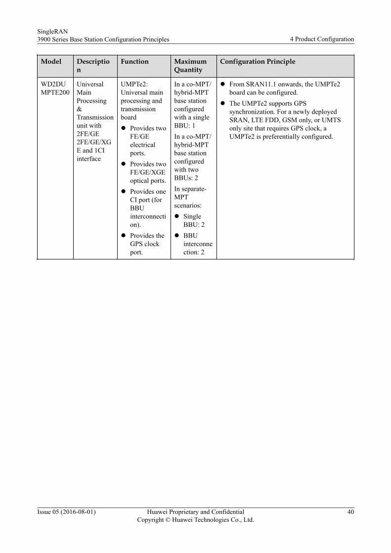
Model Description
Function MaximumQuantity
Configuration Principle
WD2DUMPTE200
UniversalMainProcessing&Transmissionunit with2FE/GE2FE/GE/XGE and 1CIinterface
UMPTe2:Universal mainprocessing andtransmissionboardl Provides two
FE/GEelectricalports.
l Provides twoFE/GE/XGEoptical ports.
l Provides oneCI port (forBBUinterconnection).
l Provides theGPS clockport.
In a co-MPT/hybrid-MPTbase stationconfiguredwith a singleBBU: 1In a co-MPT/hybrid-MPTbase stationconfiguredwith twoBBUs: 2In separate-MPTscenarios:l Single
BBU: 2l BBU
interconnection: 2
l From SRAN11.1 onwards, the UMPTe2board can be configured.
l The UMPTe2 supports GPSsynchronization. For a newly deployedSRAN, LTE FDD, GSM only, or UMTSonly site that requires GPS clock, aUMPTe2 is preferentially configured.
SingleRAN3900 Series Base Station Configuration Principles 4 Product Configuration
Issue 05 (2016-08-01) Huawei Proprietary and ConfidentialCopyright © Huawei Technologies Co., Ltd.
40
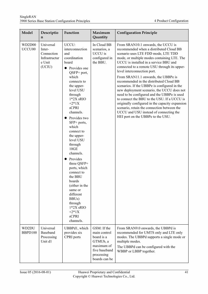
Model Description
Function MaximumQuantity
Configuration Principle
WD2D00UCCU00
UniversalInter-ConnectionInfrastructure Unit(UCIU)
UCCU:interconnectionandcoordinationboardl Provides one
QSFP+ port,whichconnects tothe upper-level USUthrough1*2X sRIO+2*1XsCPRIchannels.
l Provides twoSFP+ ports,whichconnect tothe upper-level USUthrough10GEchannels.
l Providesthree QSFP+ports, whichconnect tothe BBUboards(either in thesame ordifferentBBUs)through1*2X sRIO+2*1XsCPRIchannels.
In Cloud BBscenarios, aUCCU isconfigured inthe BBU.
From SRAN10.1 onwards, the UCCU isrecommended when a distributed Cloud BBscenario uses LTE FDD mode, LTE TDDmode, or multiple modes containing LTE. TheUCCU is installed in a service BBU andconnected to a remote USU through its upper-level interconnection port.From SRAN11.1 onwards, the UBBPe isrecommended in the distributed Cloud BBscenarios. If the UBBPe is configured in thenew deployment scenario, the UCCU does notneed to be configured and the UBBPe is usedto connect the BBU to the USU. If a UCCU isoriginally configured in the capacity expansionscenario, retain the connection between theUCCU and USU instead of connecting theHEI port on the UBBPe to the USU.
WD2DUBBPD100
UniversalBasebandProcessingUnit d1
UBBPd1, whichprovides sixCPRI ports
GSM: If themain controlboard is aGTMUb, amaximum offive basebandprocessingboards can be
From SRAN9.0 onwards, the UBBPd isrecommended for UMTS only and LTE onlymodes. The UBBPd supports a single mode ormultiple modes.The UBBPd can be configured with theWBBP or LBBP together.
SingleRAN3900 Series Base Station Configuration Principles 4 Product Configuration
Issue 05 (2016-08-01) Huawei Proprietary and ConfidentialCopyright © Huawei Technologies Co., Ltd.
41
Model Description
Function MaximumQuantity
Configuration Principle
WD2DUBBPD200
UniversalBasebandProcessingUnit d2
configured. Ifthe maincontrol boardis a UMPT, amaximum ofsix basebandprocessingboards can beconfigured.UMTS/LTE:A maximumof sixbasebandprocessingboards can beconfigured.
During capacity expansion, it is recommendedthat the existing baseband processing boardsbe configured with the maximum capacity andthe UBBPd be configured if the requiredcapacity is not reached.GSM only mode:l From GBSS16.0 onwards, the UBBP must
be configured when the VAMOS FR,VAMOS II, 4-Antenna Receive Diversity,Antenna Frequency Hopping, and MICCfeatures need to be supported.
UMTS only mode:l From RAN15.0 onwards, the UBBPd is
recommended for UMTS only mode.LTE only mode:l In eRAN7.0, the following UBBP boards
support LTE only mode: UBBPd3,UBBPd4, UBBPd5, and UBBPd6.
l From eRAN7.0/eRAN8.1/eRAN11.0(SRAN9.0/SRAN10.1/SRAN11.0)onwards, the cell configuration principlesfor the UBBPd4, UBBPd5, and UBBPd6 inLTE only mode are as follows:– A UBBPd4 does not support a hybrid
configuration of 1R and 4R cells, or 2Rand 4R cells.
– In SRAN9.0 (V100R009C00SPC210)or later, a UBBPd5 supports a hybridconfiguration of 1R and 4R cells, or 2Rand 4R cells. In a hybrid configuration,a maximum of three cells are supported.
– In SRAN9.0 (V100R009C00SPC210)or later, a UBBPd6 supports a hybridconfiguration of 1R and 4R cells, or 2Rand 4R cells. In a hybrid configuration,a maximum of three 1R or 2R cells andthree 4R cells are supported.
– After being converted from a non-hybrid configuration to a hybridconfiguration of 2R and 4R cells, theUBBPd6 must be reset.
l In eRAN8.0/SRAN10.0, the cellconfiguration principles for the UBBPd4,UBBPd5, and UBBPd6 in LTE only modeare as follows:
UBBPd2, whichprovides sixCPRI ports
WD2DUBBPD300
UniversalBasebandProcessingUnit d3
UBBPd3, whichprovides sixCPRI ports
WD2DUBBPD400
UniversalBasebandProcessingUnit d4
UBBPd4, whichprovides sixCPRI ports
WD2DUBBPD500
UniversalBasebandProcessingUnit d5
UBBPd5, whichprovides sixCPRI ports
SingleRAN3900 Series Base Station Configuration Principles 4 Product Configuration
Issue 05 (2016-08-01) Huawei Proprietary and ConfidentialCopyright © Huawei Technologies Co., Ltd.
42
Model Description
Function MaximumQuantity
Configuration Principle
WD2DUBBPD600
UniversalBasebandProcessingUnit d6
UBBPd6, whichprovides sixCPRI ports
– The UBBPd cannot be configured with2R and 4R cells together.
l In eRAN11.1/SRAN11.1 and later, thesector configuration principles for theUBBPd4, UBBPd5, and UBBPd6 in LTEonly mode are as follows:– The UBBPd4/UBBPd5/UBBPd6 can be
configured any hybrid configuration of2R and 4R cells within thespecifications.
In co-BBP multimode scenarios:l To support GU mode, the UBBPd1,
UBBPd2, UBBPd3, UBBPd4, UBBPd5, orUBBPd6 must be configured.
l To support GL mode, the UBBPd3,UBBPd4, UBBPd5, or UBBPd6 must beconfigured.
l To support UL/GUL mode, the UBBPd6 orUBBPe must be configured.– In versions earlier than SRAN11.1, a
UBBPd6 working in UL/GUL modecannot be configured with 2T2R and2T4R or 2T2R and 4T4R cells together.In SRAN11.1 and later, a UBBPd6working in LTE mode can beconfigured with 2T2R, 2T4R, and 4T4Rsectors together.
A UBBP in the centralized Cloud BB scenariocannot work in multiple modes.
WD2DUBBPE100
UniversalBasebandProcessingUnit e1
UBBPe1, whichprovides sixCPRI ports
In UMTS orLTE mode, amaximum ofsix boardscan beconfigured.
From SRAN11.1 onwards, the UBBPe canserve UO, LO, UL, and FT modes. TheUBBPe supports a single mode or multiplemodes. The UBBPe cannot process GSMbaseband signals.Any board from the UBBPe1 to UBBPe4 canbe configured in the BBU3900 or BBU3910.Any board from the UBBPe1 to UBBPe4 canbe configured with the UBBPd, WBBP, andLBBP together.l UMTS only mode:From RAN18.1 onwards, a UMTS only basestation serving six or fewer cells can beconfigured with the UBBPe1 or UBBPe2. Fora UMTS only base station serving 12 cells, the
WD2DUBBPE200
UniversalBasebandProcessingUnit e2
UBBPe2, whichprovides sixCPRI ports
In UMTS orLTE mode, amaximum ofsix boardscan beconfigured.
SingleRAN3900 Series Base Station Configuration Principles 4 Product Configuration
Issue 05 (2016-08-01) Huawei Proprietary and ConfidentialCopyright © Huawei Technologies Co., Ltd.
43
Model Description
Function MaximumQuantity
Configuration Principle
WD2DUBBPE300
UniversalBasebandProcessingUnit e3
UBBPe3 is recommended or the UBBPe4 canbe configured for the sake of transition to LTE.l LTE only mode:-From eRAN11.1 onwards, the UBBPe1 orUBBPe2 can be configured to support threecells in LTE FDD mode and the UBBPe3 orUBBPe4 is recommended for theconfiguration of six cells in LTE FDD mode.-For the LTE FDD mode, the UBBPe2 orUBBPe4 supports any hybrid configurations of2R and 4R cells within the specifications ofthe board.l In co-BBP multimode scenarios:-To support UL baseband concurrency, theUBBPe3 or UBBPe4 is recommended.-For the LTE FDD mode, the UBBPe2 orUBBPe4 supports any hybrid configurations of2R and 4R cells within the specifications ofthe board.
A UBBP in the centralized Cloud BB scenariocannot work in multiple modes.
UBBPe3, whichprovides sixCPRI ports
In UMTS orLTE mode, amaximum ofsix boardscan beconfigured.
WD2DUBBPE400
UniversalBasebandProcessingUnit e4
UBBPe4, whichprovides sixCPRI ports
In UMTS orLTE mode, amaximum ofsix boardscan beconfigured.
4.2.3.5 Clock and Transmission Board ConfigurationsThis section describes the principles for configuring clock and transmission boards in a BBU.
In SRAN6.0, three modes can be deployed in two BBUs, which work in GU+L or GL+Umode. The two BBUs do not support co-transmission or co-clock. In GU+L mode, L isregarded as LTE only mode. In GL+U mode, U is regarded as UMTS only mode.
In SRAN7.0, two BBUs can be interconnected to support three modes, such as GU+L(G) andGL+U(G). In addition, co-clock and co-transmission are supported in BBU interconnectionscenarios. In SRAN7.0, the UMPT is introduced to support the mainstream solution of co-transmission. The UTRPc is used for the alternative solution of co-transmission.
In RAN14.0, the UTRPa is introduced (used only for UMTS) to replace the UTRP3 andUTRP4, which will enter the EOM phase.
In SRAN8.0, co-MPT is introduced. In co-MPT scenarios, co-transmission is recommended.
The following table lists the principles for configuring clock and transmission boards in aBBU.
SingleRAN3900 Series Base Station Configuration Principles 4 Product Configuration
Issue 05 (2016-08-01) Huawei Proprietary and ConfidentialCopyright © Huawei Technologies Co., Ltd.
44
Table 4-18 Principles for configuring clock and transmission boards in a BBU
Model Description
Function MaximumQuantity
Configuration Principle
WD2D00USCU00
UniversalSatelliteClockUnit
USCUb11:clock boardused for LTE,without asatellite card
1 This board needs to be configured for the LTE mode whenany of the following conditions is met:l A BITS reference clock is used for LTE mode.l The LTE mode is not configured on a main control
board that has a built-in GPS satellite card but the LTEmode requires the GPS function.
l The 1PPS or RGPS clock is used for the LTE mode.
WD2D0USCU300
UniversalSynchronizationClockUnitSupporting GPSand BITS
USCUb14:USCU satellitecard clockboard, with abuilt-in u-bloxGPS satellitecard
1 This board is optional and can be configured fromSRAN7.0, GBSS14.0, RAN14.0, or eRAN5.0 onwards.l This board is required when GPS or BITS clock
synchronization is used for the GSM or UMTS mode.l This board is required when a BITS reference clock is
used for LTE mode.l This board is configured when the LTE mode is not
configured with a main control board that has a built-inGPS satellite card but requires the GPS or OTDOAfunction.
l This board is configured when the UMTS moderequires the OTDOA function.
l In GU/GL/UL dual-mode base station, this board isconfigured when GPS or BITS clock synchronization isused for GSM or UMTS, or when BITS clocksynchronization is used for LTE.
l This board is configured in a GU/GL/UL dual-modebase station where the Common Clock feature isactivated and GPS or BITS clock synchronization isused.
l This board is required in either a single-mode ormultimode base station when the 1PPS or RGPS clockis used for the LTE mode.
WD2D00UCIU00
Universalinter-ConnectionInfrastructure Unit
UCIU: interfaceboard for BBUinterconnection
1 For a separate-MPT triple-mode base station, BBU 0 needsto be configured with the UCIU if the two BBUs areinterconnected by connecting the UCIU in one BBU andthe UMPT in the other BBU.
SingleRAN3900 Series Base Station Configuration Principles 4 Product Configuration
Issue 05 (2016-08-01) Huawei Proprietary and ConfidentialCopyright © Huawei Technologies Co., Ltd.
45
Model Description
Function MaximumQuantity
Configuration Principle
GM5DUTRPB400
GSMTDMoverE1/T1InterfaceUnit
UTRPb4: GSMtransmissionextension boardProvides eightTDM overE1/T1 ports.
1 This board is configured when five to eight E1/T1s arerequired by GSM mode.
QWMD0UTRP300
Iub ATMInterfaceUnit (8E1s)
UTRP3: UMTStransmissionextension boardProvides eightATM over E1ports.
4 This board is required when the E1/T1 ports on the mainprocessing and transmission board in UMTS mode supportATM transmission and more than four ATM over E1/T1ports are required.
QWMP0UTRP400
Iub IPInterfaceUnit (8E1s)
UTRP4: UMTStransmissionextension boardProvides eightIP over E1ports.
4 This board is required when the E1 ports on the mainprocessing and transmission board in UMTS mode supportIP transmission and more than four IP over E1 ports arerequired.
QWMP0UTRP900
Iub IPInterfaceUnit (4FE/GEElectricalports)
UTRP9: UMTStransmissionextension boardProvides fourFE/GEelectrical ports.
4 This board is required when two or more FE/GE electricalports are used by UMTS.Each board provides four FE/GE electrical ports, and thenumber of the boards to be configured is determined bythe required number of FE/GE electrical ports.
QWMP0UTRP200
Iub IPInterfaceUnit (2FE/GEOpticalports)
UTRP2: UMTStransmissionextension boardProvides twoFE/GE opticalports.
4 This board is required when two or more FE/GE opticalports are used by UMTS.
QWMD0UTRP600
Iub ATMInterfaceUnit (1UnchannelizedSTM-1)
UTRP6: UMTStransmissionextension boardProvides oneunchannelizedSTM-1 port.
4 This board is required when unchannelized STM-1transmission is used by UMTS.
SingleRAN3900 Series Base Station Configuration Principles 4 Product Configuration
Issue 05 (2016-08-01) Huawei Proprietary and ConfidentialCopyright © Huawei Technologies Co., Ltd.
46
Model Description
Function MaximumQuantity
Configuration Principle
QWMD0UTRPA00
UniversalTransmissionResourceProcessing Unit (8E1s/T1s)
UTRPa: UMTStransmissionextension boardProvides eightATM or IP overE1 ports.
4 l This board is required when the E1/T1 ports on themain processing and transmission board in UMTSmode support ATM or IP transmission and more thanfour E1/T1 ports are required.
l Each board provides eight E1/T1 ports, and the numberof the boards to be configured is determined by therequired number of E1/T1 ports.
l The ATM transmission and IP transmission cannot beused together.
l The UTRPa board supports the plug-and-play functiononly in RAN14.0/RAN14.1, and this board cannot becustomized. This board can be supported only byspecific software versions of RAN15.0 and later.
QWMD0UTRPC00
UniversalTransmissionResourceProcessing Unit (4ElectricalFE/GEports & 2OpticalFE/GEports)
UTRPc: UMTStransmissionextension boardl Works in
GSM,UMTS, orLTE mode.
l Providesfour FE/GEelectricalports.
l Providestwo FE/GEoptical ports.
1 Optional. The UTRPc is introduced in SRAN7.0/GBSS14.0/RAN14.0/eRAN5.0. It can be shared by GSM,UMTS, and LTE. Since SRAN7.0, the UTRPc isrecommended for increasing FE/GE ports in all modes.Since SRAN8.0, the UTRPc is not recommended forincreasing FE/GE ports in GSM mode. When the GTMUaboard is used, the UTRPc board cannot be used fortransmission capacity expansion.l This board is required when a triple-mode base station
that uses co-transmission is not configured with aUMPT board, or is configured with a UMPT board butrequires transmission capacity expansion.
l This board is required when IPsec is used for UMTSand no UMPT is configured for UMTS.
QCUBBBULIG01
Lightening ArresterBox
SLPU: surgeprotection boxfor transmission
1 l Each surge protection box is configured with amaximum of four surge protection boards.
l A BTS3900AL cabinet contains one surge protectionbox. One piece needs to be configured when more thanfour surge protection boards are required.
WD2P00UELP00
UniversalE1/T1LighteningProtectionUnit
UELP:universal E1/T1lighteningprotection unit
- l Every four E1 ports are configured with one surgeprotection package.
l A BTS3900AL AC cabinet contains two E1 surgeprotection packages. This board needs to be configuredwhen more than two E1 surge protection packages arerequired.
SingleRAN3900 Series Base Station Configuration Principles 4 Product Configuration
Issue 05 (2016-08-01) Huawei Proprietary and ConfidentialCopyright © Huawei Technologies Co., Ltd.
47
Model Description
Function MaximumQuantity
Configuration Principle
WD2P0UFLPB00
UniversalFE/GELighteningProtectionUnit
UFLPb:universalFE/GElighteningprotection unit
- l Every two FE/GE electrical ports are configured withone surge protection package.
l A BTS3900AL AC cabinet contains one FE/GE surgeprotection package. This board needs to be configuredwhen more than one FE/GE surge protection package isrequired.
l The FE/GE surge protection package is not requiredwhen a UMPTe is configured.
WD2P0UFLPC00
UniversalFE/GELighteningProtectionUnit
UFLPc:universalFE/GElighteningprotection unit
- l Every two FE/GE electrical ports are configured withone surge protection package.
l A BTS3900AL AC cabinet contains one FE/GE surgeprotection package. This board needs to be configuredwhen more than one FE/GE surge protection package isrequired.
l The FE/GE surge protection package is not requiredwhen a UMPTe is configured.
4.3 RF Module ConfigurationsThis section describes the principles for configuring RF modules in a 3900 series base station.
4.3.1 RF Module ConfigurationsThe type of RF modules to be used is determined by the frequency band. Each sector isconfigured with at least one RF module. The number of RF modules to be configured dependson the number of sectors, number of carriers, and output power.
The following table lists the relationships between sectors and RF modules.
Table 4-19 RF module configurations
Configuration Scenario RF Module Configuration
Transmit diversity
2x2 MIMO
MIMO Prime
Two TX channels are required for one sector:
l Two 1T modulesa are configured for one sector.
l One 2Tb or 4T module is configured for one sector.
DL 4x2 MIMODL 4x4 MIMO
Four TX channels are required for one sector:l Two 2T modules are configured for one sector.l One 4T module is configured for one sector.NOTE
1T modules cannot be used in this configuration scenario.
SingleRAN3900 Series Base Station Configuration Principles 4 Product Configuration
Issue 05 (2016-08-01) Huawei Proprietary and ConfidentialCopyright © Huawei Technologies Co., Ltd.
48
Configuration Scenario RF Module Configuration
UL 4-way DiversityUL 2x4 multi-user MIMO(MU-MIMO)
Four RX channels are required for one sector:l Two 2R modules are configured for one sector.l One 4R module is configured for one sector.
a: In versions earlier than SRAN6.0, when two 1T RF modules are configured to support MIMO, the two RFmodules must be cascaded by connecting CPRI ports. From SRAN6.0 onwards, it is recommended that the twoRF modules be cascaded by connecting CPRI ports.b: For 2T RF modules that support UMTS mode among other modes, the UMTS mode of two 2T RF modulesserving one sector supports UL 4-way diversity but does not support carrier or power expansion. If RFUs andRRUs are used in the same base station, they cannot operate in the same frequency band.
The application scenarios supported by RF modules vary according to the working mode ofthe RF modules, as shown in the following table.
Table 4-20 RF module configuration restrictions
Mode Restriction
GSM l The DRFUs support UL 4-way diversity.l From GBSS16.0/SRAN9.0 onwards, UL 4-way diversity is supported by a base
station where GSM baseband signals are processed by the UBBPd.l The RRU3004, DRFU, and 2T RF modules support the transmit diversity.l When UL 4-way diversity is used, two DRFUs must be configured.l When PBT or transmit diversity is used, each DRFU or RRU3004 supports only
one TRX. Each cell served by the DRFU or RRU3004 supports a maximum of twoTRXs. When transmit diversity is used, the maximum number of carriers supportedby each GSM RF module with two transmit channels decreases by half.
l The DRFU or RRU3004 supporting transmit diversity does not support PBT.l When UL 4-way diversity is used, the DRFU does not support TMA. When 4-way
diversity is used, each cell supports a maximum of two TRXs.NOTE
The DRFU or RRU3004 cannot be used in an eGBTS.
UMTS l RFUs support transmit diversity, 2x2 MIMO, and UL 4-way diversity.l RRUs support DL transmit diversity, 2x2 MIMO, and UL 4-way diversity.
LTE The following configuration scenarios are supported: 2x2 MIMO, SIMO, UL 4-waydiversity, DL 4x2 MIMO, UL 2x4 MU-MIMO, and DL 4x4 MIMO. When DL 4x2MIMO or DL 4x4 MIMO is used, two cascaded 2T RF modules or one 4T RF moduleis required. 1T RF modules do not support DL 4x2 MIMO or DL 4x4 MIMO.
NOTEWhen the SingleOM solution is used, GSM RF signals do not support transmit diversity.
SingleRAN3900 Series Base Station Configuration Principles 4 Product Configuration
Issue 05 (2016-08-01) Huawei Proprietary and ConfidentialCopyright © Huawei Technologies Co., Ltd.
49
4.3.2 RF Modules Working at Band 31 (450 MHz)This section describes the principles for configuring RF modules working at band 31 (450MHz).
RF Modules Working at Band 31 (450 MHz)The following table lists RRU configurations.
Table 4-21 RRU configurations
Model Description Function Configuration Principle
WD5M450RRU05 RRU3668 formultimode 450 MHz(2x40 W)
RRU3668 working at band 31(450 MHz):l The module has two transmit
channels and its maximumoutput power is 2x40 W.
l UL: 452.5 MHz to 457.5MHz; DL: 462.5 MHz to467.5 MHz
l It can work in LTE mode.
The number of packages tobe configured is determinedby the number of sectors,number of carriers, andoutput power.For detailed specifications,see RRU TechnicalSpecifications.
4.3.3 RF Modules Working at Band 8 (900 MHz)This section describes the principles for configuring RF modules working at band 8 (900MHz).
RFUs Working at Band 8 (900 MHz)The following table lists RFU configurations.
SingleRAN3900 Series Base Station Configuration Principles 4 Product Configuration
Issue 05 (2016-08-01) Huawei Proprietary and ConfidentialCopyright © Huawei Technologies Co., Ltd.
50
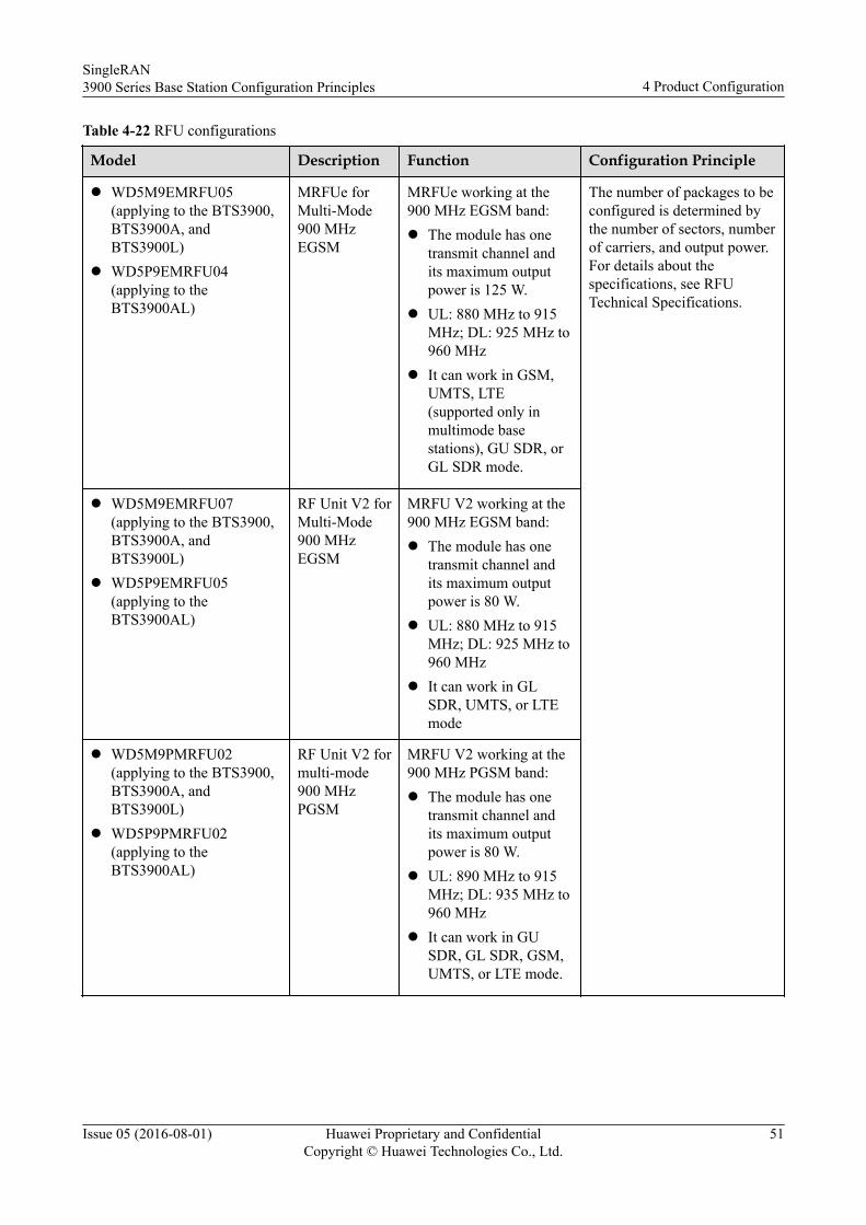
Table 4-22 RFU configurations
Model Description Function Configuration Principle
l WD5M9EMRFU05(applying to the BTS3900,BTS3900A, andBTS3900L)
l WD5P9EMRFU04(applying to theBTS3900AL)
MRFUe forMulti-Mode900 MHzEGSM
MRFUe working at the900 MHz EGSM band:l The module has one
transmit channel andits maximum outputpower is 125 W.
l UL: 880 MHz to 915MHz; DL: 925 MHz to960 MHz
l It can work in GSM,UMTS, LTE(supported only inmultimode basestations), GU SDR, orGL SDR mode.
The number of packages to beconfigured is determined bythe number of sectors, numberof carriers, and output power.For details about thespecifications, see RFUTechnical Specifications.
l WD5M9EMRFU07(applying to the BTS3900,BTS3900A, andBTS3900L)
l WD5P9EMRFU05(applying to theBTS3900AL)
RF Unit V2 forMulti-Mode900 MHzEGSM
MRFU V2 working at the900 MHz EGSM band:l The module has one
transmit channel andits maximum outputpower is 80 W.
l UL: 880 MHz to 915MHz; DL: 925 MHz to960 MHz
l It can work in GLSDR, UMTS, or LTEmode
l WD5M9PMRFU02(applying to the BTS3900,BTS3900A, andBTS3900L)
l WD5P9PMRFU02(applying to theBTS3900AL)
RF Unit V2 formulti-mode900 MHzPGSM
MRFU V2 working at the900 MHz PGSM band:l The module has one
transmit channel andits maximum outputpower is 80 W.
l UL: 890 MHz to 915MHz; DL: 935 MHz to960 MHz
l It can work in GUSDR, GL SDR, GSM,UMTS, or LTE mode.
SingleRAN3900 Series Base Station Configuration Principles 4 Product Configuration
Issue 05 (2016-08-01) Huawei Proprietary and ConfidentialCopyright © Huawei Technologies Co., Ltd.
51
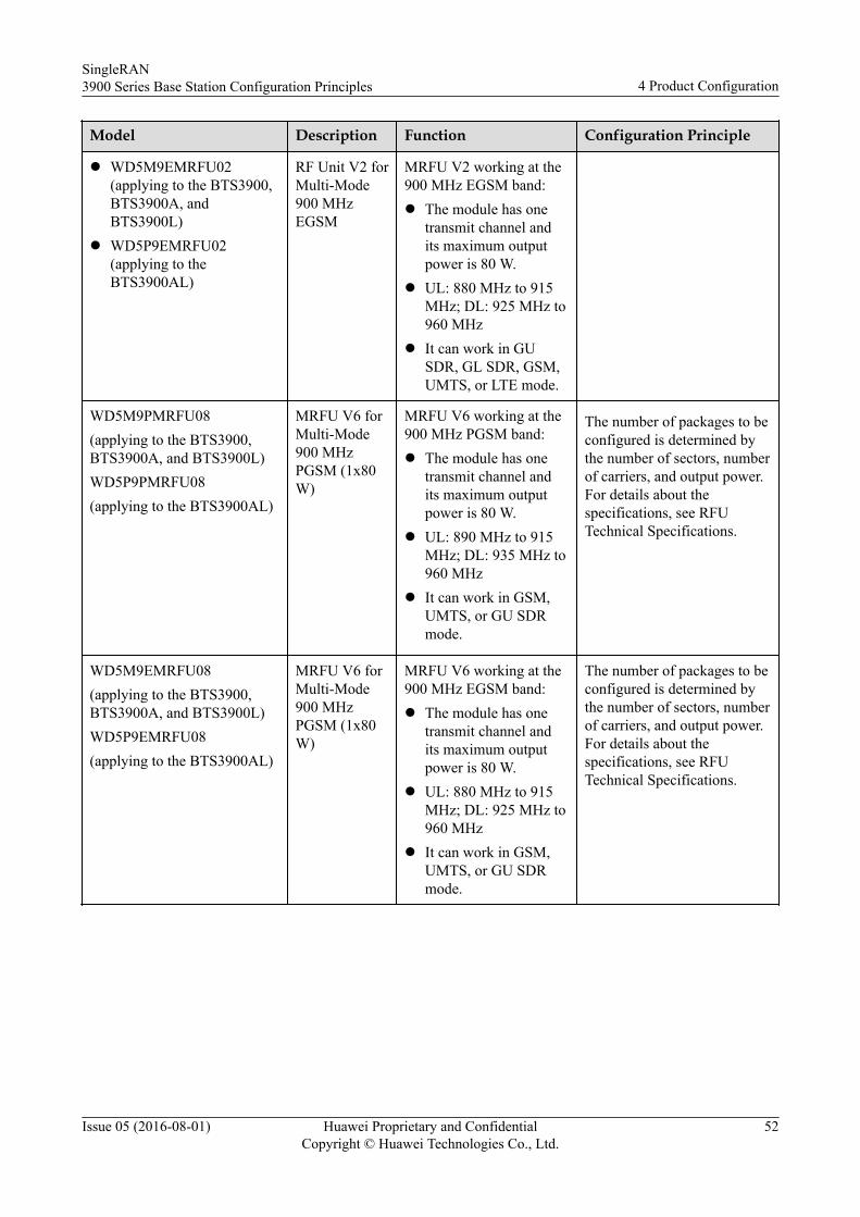
Model Description Function Configuration Principle
l WD5M9EMRFU02(applying to the BTS3900,BTS3900A, andBTS3900L)
l WD5P9EMRFU02(applying to theBTS3900AL)
RF Unit V2 forMulti-Mode900 MHzEGSM
MRFU V2 working at the900 MHz EGSM band:l The module has one
transmit channel andits maximum outputpower is 80 W.
l UL: 880 MHz to 915MHz; DL: 925 MHz to960 MHz
l It can work in GUSDR, GL SDR, GSM,UMTS, or LTE mode.
WD5M9PMRFU08(applying to the BTS3900,BTS3900A, and BTS3900L)WD5P9PMRFU08(applying to the BTS3900AL)
MRFU V6 forMulti-Mode900 MHzPGSM (1x80W)
MRFU V6 working at the900 MHz PGSM band:l The module has one
transmit channel andits maximum outputpower is 80 W.
l UL: 890 MHz to 915MHz; DL: 935 MHz to960 MHz
l It can work in GSM,UMTS, or GU SDRmode.
The number of packages to beconfigured is determined bythe number of sectors, numberof carriers, and output power.For details about thespecifications, see RFUTechnical Specifications.
WD5M9EMRFU08(applying to the BTS3900,BTS3900A, and BTS3900L)WD5P9EMRFU08(applying to the BTS3900AL)
MRFU V6 forMulti-Mode900 MHzPGSM (1x80W)
MRFU V6 working at the900 MHz EGSM band:l The module has one
transmit channel andits maximum outputpower is 80 W.
l UL: 880 MHz to 915MHz; DL: 925 MHz to960 MHz
l It can work in GSM,UMTS, or GU SDRmode.
The number of packages to beconfigured is determined bythe number of sectors, numberof carriers, and output power.For details about thespecifications, see RFUTechnical Specifications.
SingleRAN3900 Series Base Station Configuration Principles 4 Product Configuration
Issue 05 (2016-08-01) Huawei Proprietary and ConfidentialCopyright © Huawei Technologies Co., Ltd.
52
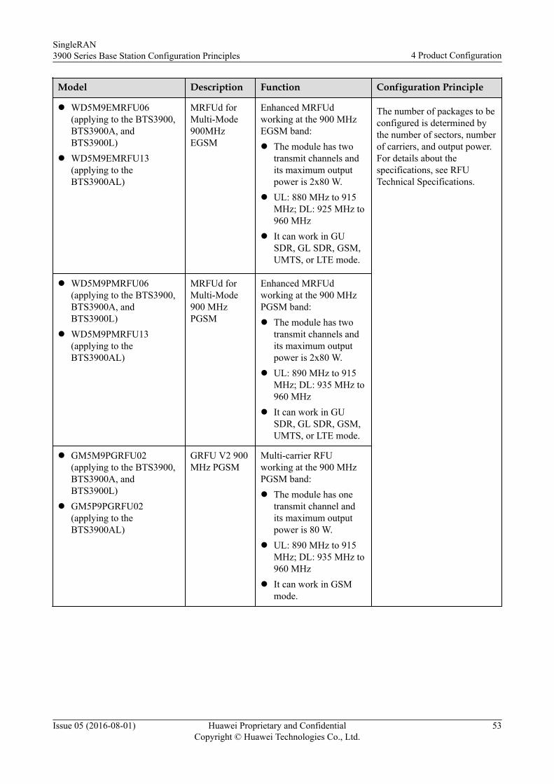
Model Description Function Configuration Principle
l WD5M9EMRFU06(applying to the BTS3900,BTS3900A, andBTS3900L)
l WD5M9EMRFU13(applying to theBTS3900AL)
MRFUd forMulti-Mode900MHzEGSM
Enhanced MRFUdworking at the 900 MHzEGSM band:l The module has two
transmit channels andits maximum outputpower is 2x80 W.
l UL: 880 MHz to 915MHz; DL: 925 MHz to960 MHz
l It can work in GUSDR, GL SDR, GSM,UMTS, or LTE mode.
The number of packages to beconfigured is determined bythe number of sectors, numberof carriers, and output power.For details about thespecifications, see RFUTechnical Specifications.
l WD5M9PMRFU06(applying to the BTS3900,BTS3900A, andBTS3900L)
l WD5M9PMRFU13(applying to theBTS3900AL)
MRFUd forMulti-Mode900 MHzPGSM
Enhanced MRFUdworking at the 900 MHzPGSM band:l The module has two
transmit channels andits maximum outputpower is 2x80 W.
l UL: 890 MHz to 915MHz; DL: 935 MHz to960 MHz
l It can work in GUSDR, GL SDR, GSM,UMTS, or LTE mode.
l GM5M9PGRFU02(applying to the BTS3900,BTS3900A, andBTS3900L)
l GM5P9PGRFU02(applying to theBTS3900AL)
GRFU V2 900MHz PGSM
Multi-carrier RFUworking at the 900 MHzPGSM band:l The module has one
transmit channel andits maximum outputpower is 80 W.
l UL: 890 MHz to 915MHz; DL: 935 MHz to960 MHz
l It can work in GSMmode.
SingleRAN3900 Series Base Station Configuration Principles 4 Product Configuration
Issue 05 (2016-08-01) Huawei Proprietary and ConfidentialCopyright © Huawei Technologies Co., Ltd.
53
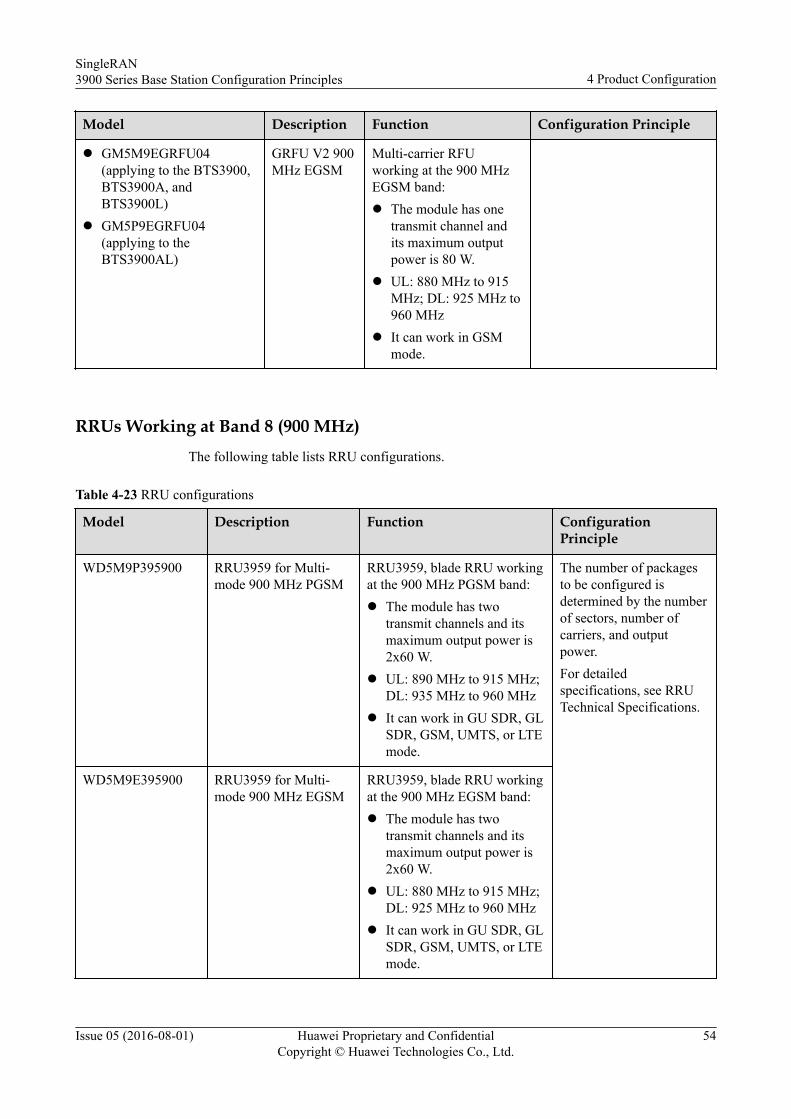
Model Description Function Configuration Principle
l GM5M9EGRFU04(applying to the BTS3900,BTS3900A, andBTS3900L)
l GM5P9EGRFU04(applying to theBTS3900AL)
GRFU V2 900MHz EGSM
Multi-carrier RFUworking at the 900 MHzEGSM band:l The module has one
transmit channel andits maximum outputpower is 80 W.
l UL: 880 MHz to 915MHz; DL: 925 MHz to960 MHz
l It can work in GSMmode.
RRUs Working at Band 8 (900 MHz)The following table lists RRU configurations.
Table 4-23 RRU configurations
Model Description Function ConfigurationPrinciple
WD5M9P395900 RRU3959 for Multi-mode 900 MHz PGSM
RRU3959, blade RRU workingat the 900 MHz PGSM band:l The module has two
transmit channels and itsmaximum output power is2x60 W.
l UL: 890 MHz to 915 MHz;DL: 935 MHz to 960 MHz
l It can work in GU SDR, GLSDR, GSM, UMTS, or LTEmode.
The number of packagesto be configured isdetermined by the numberof sectors, number ofcarriers, and outputpower.For detailedspecifications, see RRUTechnical Specifications.
WD5M9E395900 RRU3959 for Multi-mode 900 MHz EGSM
RRU3959, blade RRU workingat the 900 MHz EGSM band:l The module has two
transmit channels and itsmaximum output power is2x60 W.
l UL: 880 MHz to 915 MHz;DL: 925 MHz to 960 MHz
l It can work in GU SDR, GLSDR, GSM, UMTS, or LTEmode.
SingleRAN3900 Series Base Station Configuration Principles 4 Product Configuration
Issue 05 (2016-08-01) Huawei Proprietary and ConfidentialCopyright © Huawei Technologies Co., Ltd.
54
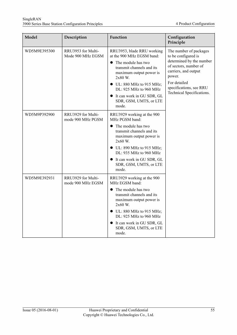
Model Description Function ConfigurationPrinciple
WD5M9E395300 RRU3953 for Multi-Mode 900 MHz EGSM
RRU3953, blade RRU workingat the 900 MHz EGSM band:l The module has two
transmit channels and itsmaximum output power is2x80 W.
l UL: 880 MHz to 915 MHz;DL: 925 MHz to 960 MHz
l It can work in GU SDR, GLSDR, GSM, UMTS, or LTEmode.
The number of packagesto be configured isdetermined by the numberof sectors, number ofcarriers, and outputpower.For detailedspecifications, see RRUTechnical Specifications.
WD5M9P392900 RRU3929 for Multi-mode 900 MHz PGSM
RRU3929 working at the 900MHz PGSM band:l The module has two
transmit channels and itsmaximum output power is2x60 W.
l UL: 890 MHz to 915 MHz;DL: 935 MHz to 960 MHz
l It can work in GU SDR, GLSDR, GSM, UMTS, or LTEmode.
WD5M9E392931 RRU3929 for Multi-mode 900 MHz EGSM
RRU3929 working at the 900MHz EGSM band:l The module has two
transmit channels and itsmaximum output power is2x60 W.
l UL: 880 MHz to 915 MHz;DL: 925 MHz to 960 MHz
l It can work in GU SDR, GLSDR, GSM, UMTS, or LTEmode.
SingleRAN3900 Series Base Station Configuration Principles 4 Product Configuration
Issue 05 (2016-08-01) Huawei Proprietary and ConfidentialCopyright © Huawei Technologies Co., Ltd.
55
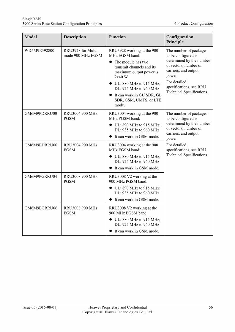
Model Description Function ConfigurationPrinciple
WD5M9E392800 RRU3928 for Multi-mode 900 MHz EGSM
RRU3928 working at the 900MHz EGSM band:l The module has two
transmit channels and itsmaximum output power is2x40 W.
l UL: 880 MHz to 915 MHz;DL: 925 MHz to 960 MHz
l It can work in GU SDR, GLSDR, GSM, UMTS, or LTEmode.
The number of packagesto be configured isdetermined by the numberof sectors, number ofcarriers, and outputpower.For detailedspecifications, see RRUTechnical Specifications.
GM6M9PDRRU00 RRU3004 900 MHzPGSM
RRU3004 working at the 900MHz PGSM band:l UL: 890 MHz to 915 MHz;
DL: 935 MHz to 960 MHzl It can work in GSM mode.
The number of packagesto be configured isdetermined by the numberof sectors, number ofcarriers, and outputpower.For detailedspecifications, see RRUTechnical Specifications.
GM6M9EDRRU00 RRU3004 900 MHzEGSM
RRU3004 working at the 900MHz EGSM band:l UL: 880 MHz to 915 MHz;
DL: 925 MHz to 960 MHzl It can work in GSM mode.
GM6M9PGRRU04 RRU3008 900 MHzPGSM
RRU3008 V2 working at the900 MHz PGSM band:l UL: 890 MHz to 915 MHz;
DL: 935 MHz to 960 MHzl It can work in GSM mode.
GM6M9EGRRU06 RRU3008 900 MHzEGSM
RRU3008 V2 working at the900 MHz EGSM band:l UL: 880 MHz to 915 MHz;
DL: 925 MHz to 960 MHzl It can work in GSM mode.
SingleRAN3900 Series Base Station Configuration Principles 4 Product Configuration
Issue 05 (2016-08-01) Huawei Proprietary and ConfidentialCopyright © Huawei Technologies Co., Ltd.
56
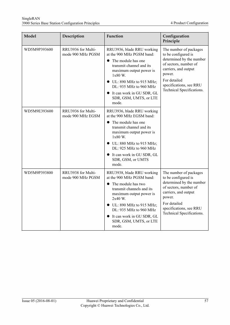
Model Description Function ConfigurationPrinciple
WD5M9P393600 RRU3936 for Multi-mode 900 MHz PGSM
RRU3936, blade RRU workingat the 900 MHz PGSM band:l The module has one
transmit channel and itsmaximum output power is1x80 W.
l UL: 890 MHz to 915 MHz;DL: 935 MHz to 960 MHz
l It can work in GU SDR, GLSDR, GSM, UMTS, or LTEmode.
The number of packagesto be configured isdetermined by the numberof sectors, number ofcarriers, and outputpower.For detailedspecifications, see RRUTechnical Specifications.
WD5M9E393600 RRU3936 for Multi-mode 900 MHz EGSM
RRU3936, blade RRU workingat the 900 MHz EGSM band:l The module has one
transmit channel and itsmaximum output power is1x80 W.
l UL: 880 MHz to 915 MHz;DL: 925 MHz to 960 MHz
l It can work in GU SDR, GLSDR, GSM, or UMTSmode.
WD5M9P393800 RRU3938 for Multi-mode 900 MHz PGSM
RRU3938, blade RRU workingat the 900 MHz PGSM band:l The module has two
transmit channels and itsmaximum output power is2x40 W.
l UL: 890 MHz to 915 MHz;DL: 935 MHz to 960 MHz
l It can work in GU SDR, GLSDR, GSM, UMTS, or LTEmode.
The number of packagesto be configured isdetermined by the numberof sectors, number ofcarriers, and outputpower.For detailedspecifications, see RRUTechnical Specifications.
SingleRAN3900 Series Base Station Configuration Principles 4 Product Configuration
Issue 05 (2016-08-01) Huawei Proprietary and ConfidentialCopyright © Huawei Technologies Co., Ltd.
57
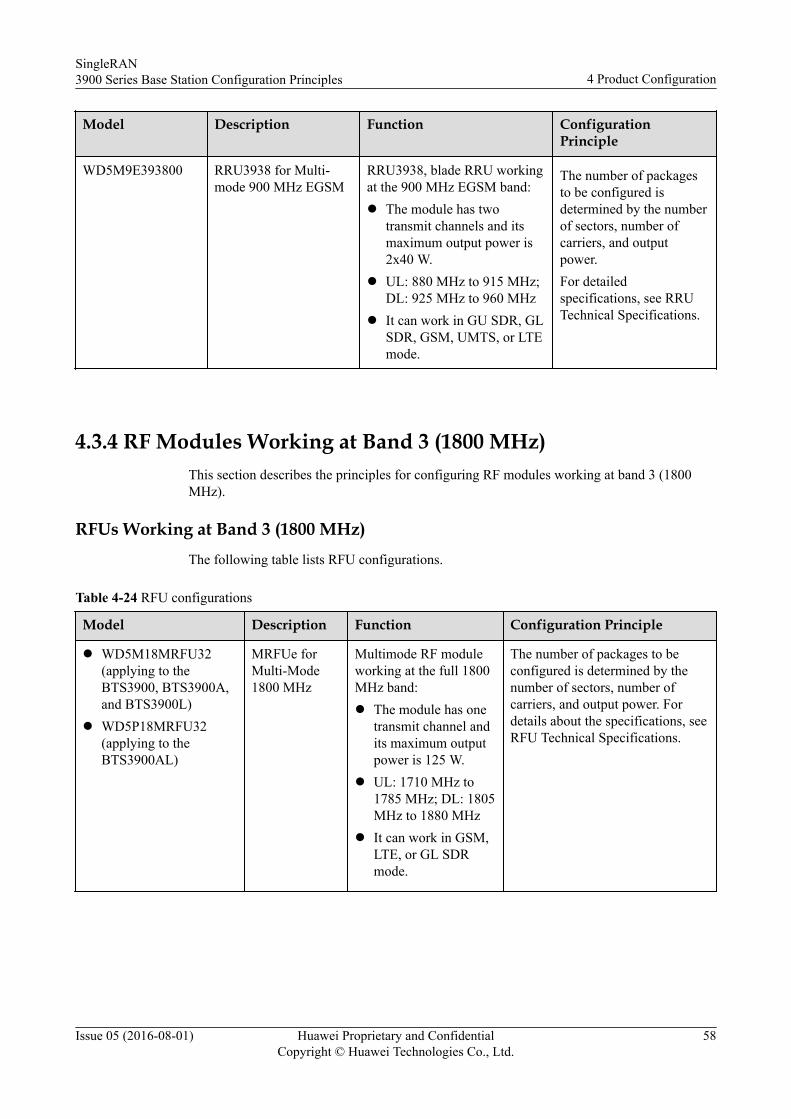
Model Description Function ConfigurationPrinciple
WD5M9E393800 RRU3938 for Multi-mode 900 MHz EGSM
RRU3938, blade RRU workingat the 900 MHz EGSM band:l The module has two
transmit channels and itsmaximum output power is2x40 W.
l UL: 880 MHz to 915 MHz;DL: 925 MHz to 960 MHz
l It can work in GU SDR, GLSDR, GSM, UMTS, or LTEmode.
The number of packagesto be configured isdetermined by the numberof sectors, number ofcarriers, and outputpower.For detailedspecifications, see RRUTechnical Specifications.
4.3.4 RF Modules Working at Band 3 (1800 MHz)This section describes the principles for configuring RF modules working at band 3 (1800MHz).
RFUs Working at Band 3 (1800 MHz)The following table lists RFU configurations.
Table 4-24 RFU configurations
Model Description Function Configuration Principle
l WD5M18MRFU32(applying to theBTS3900, BTS3900A,and BTS3900L)
l WD5P18MRFU32(applying to theBTS3900AL)
MRFUe forMulti-Mode1800 MHz
Multimode RF moduleworking at the full 1800MHz band:l The module has one
transmit channel andits maximum outputpower is 125 W.
l UL: 1710 MHz to1785 MHz; DL: 1805MHz to 1880 MHz
l It can work in GSM,LTE, or GL SDRmode.
The number of packages to beconfigured is determined by thenumber of sectors, number ofcarriers, and output power. Fordetails about the specifications, seeRFU Technical Specifications.
SingleRAN3900 Series Base Station Configuration Principles 4 Product Configuration
Issue 05 (2016-08-01) Huawei Proprietary and ConfidentialCopyright © Huawei Technologies Co., Ltd.
58
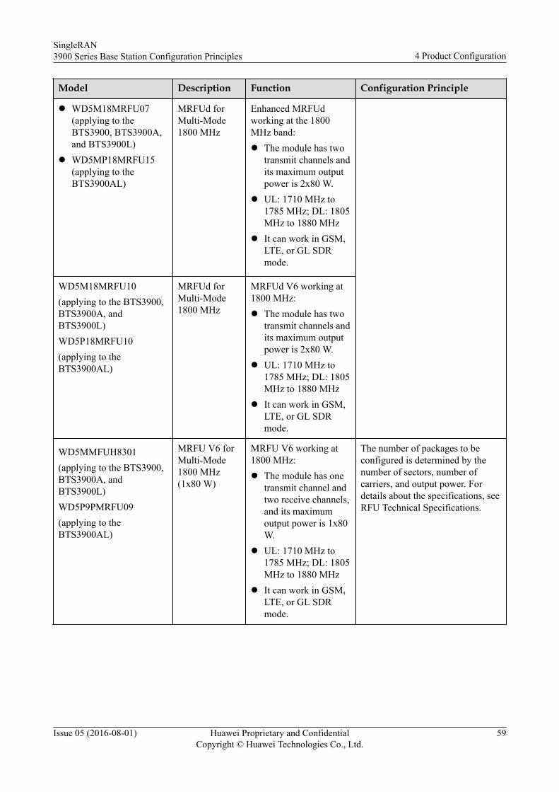
Model Description Function Configuration Principle
l WD5M18MRFU07(applying to theBTS3900, BTS3900A,and BTS3900L)
l WD5MP18MRFU15(applying to theBTS3900AL)
MRFUd forMulti-Mode1800 MHz
Enhanced MRFUdworking at the 1800MHz band:l The module has two
transmit channels andits maximum outputpower is 2x80 W.
l UL: 1710 MHz to1785 MHz; DL: 1805MHz to 1880 MHz
l It can work in GSM,LTE, or GL SDRmode.
WD5M18MRFU10(applying to the BTS3900,BTS3900A, andBTS3900L)WD5P18MRFU10(applying to theBTS3900AL)
MRFUd forMulti-Mode1800 MHz
MRFUd V6 working at1800 MHz:l The module has two
transmit channels andits maximum outputpower is 2x80 W.
l UL: 1710 MHz to1785 MHz; DL: 1805MHz to 1880 MHz
l It can work in GSM,LTE, or GL SDRmode.
WD5MMFUH8301(applying to the BTS3900,BTS3900A, andBTS3900L)WD5P9PMRFU09(applying to theBTS3900AL)
MRFU V6 forMulti-Mode1800 MHz(1x80 W)
MRFU V6 working at1800 MHz:l The module has one
transmit channel andtwo receive channels,and its maximumoutput power is 1x80W.
l UL: 1710 MHz to1785 MHz; DL: 1805MHz to 1880 MHz
l It can work in GSM,LTE, or GL SDRmode.
The number of packages to beconfigured is determined by thenumber of sectors, number ofcarriers, and output power. Fordetails about the specifications, seeRFU Technical Specifications.
SingleRAN3900 Series Base Station Configuration Principles 4 Product Configuration
Issue 05 (2016-08-01) Huawei Proprietary and ConfidentialCopyright © Huawei Technologies Co., Ltd.
59
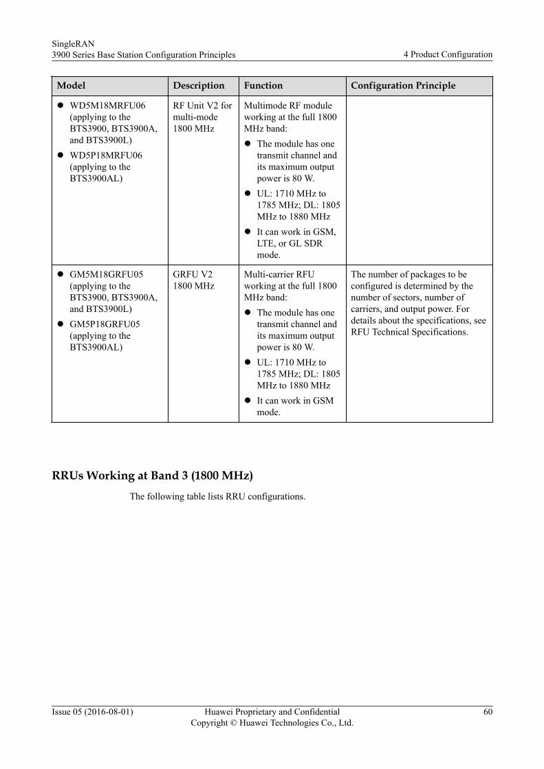
Model Description Function Configuration Principle
l WD5M18MRFU06(applying to theBTS3900, BTS3900A,and BTS3900L)
l WD5P18MRFU06(applying to theBTS3900AL)
RF Unit V2 formulti-mode1800 MHz
Multimode RF moduleworking at the full 1800MHz band:l The module has one
transmit channel andits maximum outputpower is 80 W.
l UL: 1710 MHz to1785 MHz; DL: 1805MHz to 1880 MHz
l It can work in GSM,LTE, or GL SDRmode.
l GM5M18GRFU05(applying to theBTS3900, BTS3900A,and BTS3900L)
l GM5P18GRFU05(applying to theBTS3900AL)
GRFU V21800 MHz
Multi-carrier RFUworking at the full 1800MHz band:l The module has one
transmit channel andits maximum outputpower is 80 W.
l UL: 1710 MHz to1785 MHz; DL: 1805MHz to 1880 MHz
l It can work in GSMmode.
The number of packages to beconfigured is determined by thenumber of sectors, number ofcarriers, and output power. Fordetails about the specifications, seeRFU Technical Specifications.
RRUs Working at Band 3 (1800 MHz)The following table lists RRU configurations.
SingleRAN3900 Series Base Station Configuration Principles 4 Product Configuration
Issue 05 (2016-08-01) Huawei Proprietary and ConfidentialCopyright © Huawei Technologies Co., Ltd.
60
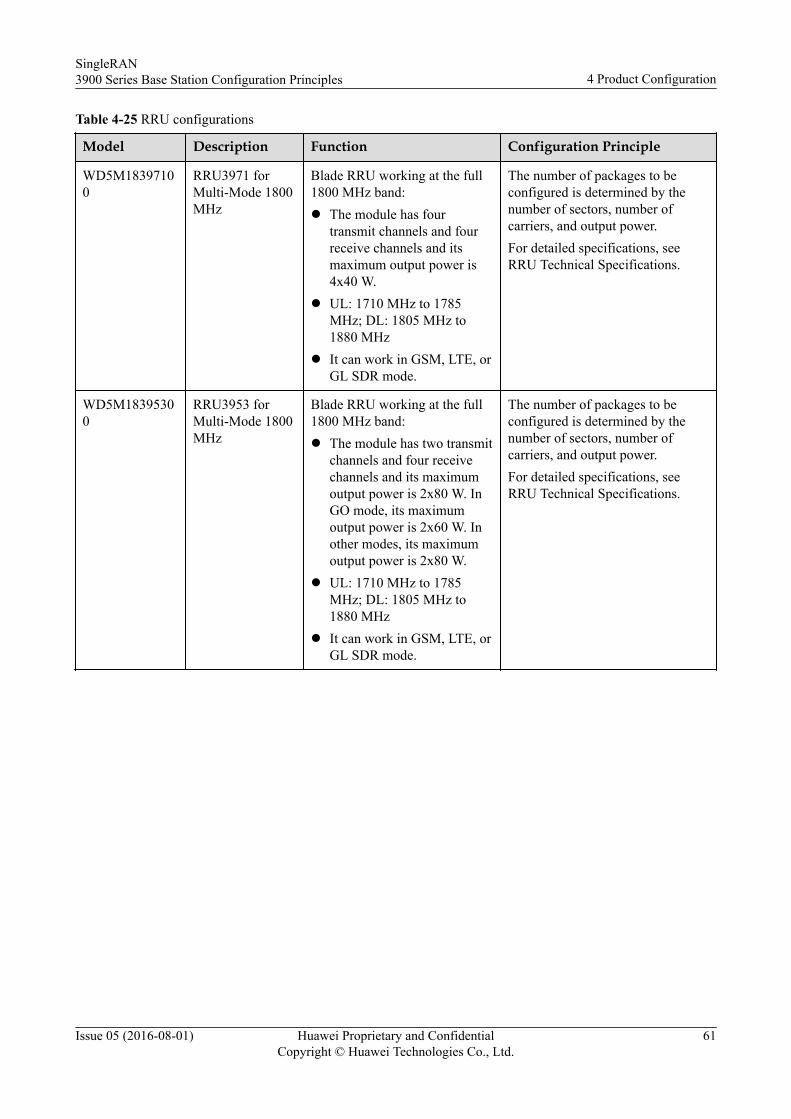
Table 4-25 RRU configurations
Model Description Function Configuration Principle
WD5M18397100
RRU3971 forMulti-Mode 1800MHz
Blade RRU working at the full1800 MHz band:l The module has four
transmit channels and fourreceive channels and itsmaximum output power is4x40 W.
l UL: 1710 MHz to 1785MHz; DL: 1805 MHz to1880 MHz
l It can work in GSM, LTE, orGL SDR mode.
The number of packages to beconfigured is determined by thenumber of sectors, number ofcarriers, and output power.For detailed specifications, seeRRU Technical Specifications.
WD5M18395300
RRU3953 forMulti-Mode 1800MHz
Blade RRU working at the full1800 MHz band:l The module has two transmit
channels and four receivechannels and its maximumoutput power is 2x80 W. InGO mode, its maximumoutput power is 2x60 W. Inother modes, its maximumoutput power is 2x80 W.
l UL: 1710 MHz to 1785MHz; DL: 1805 MHz to1880 MHz
l It can work in GSM, LTE, orGL SDR mode.
The number of packages to beconfigured is determined by thenumber of sectors, number ofcarriers, and output power.For detailed specifications, seeRRU Technical Specifications.
SingleRAN3900 Series Base Station Configuration Principles 4 Product Configuration
Issue 05 (2016-08-01) Huawei Proprietary and ConfidentialCopyright © Huawei Technologies Co., Ltd.
61
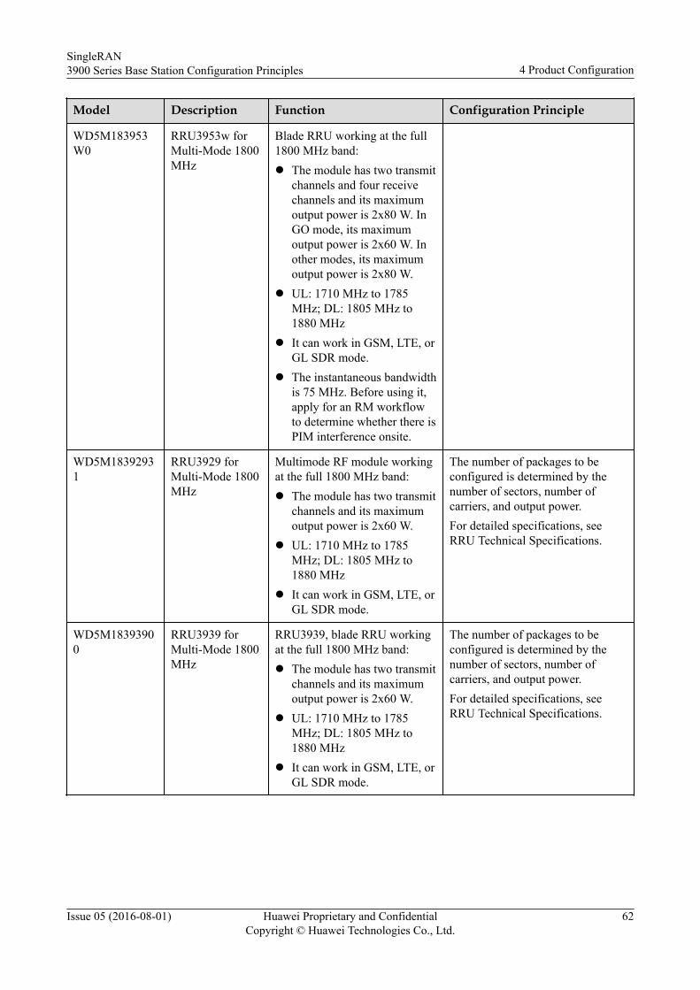
Model Description Function Configuration Principle
WD5M183953W0
RRU3953w forMulti-Mode 1800MHz
Blade RRU working at the full1800 MHz band:l The module has two transmit
channels and four receivechannels and its maximumoutput power is 2x80 W. InGO mode, its maximumoutput power is 2x60 W. Inother modes, its maximumoutput power is 2x80 W.
l UL: 1710 MHz to 1785MHz; DL: 1805 MHz to1880 MHz
l It can work in GSM, LTE, orGL SDR mode.
l The instantaneous bandwidthis 75 MHz. Before using it,apply for an RM workflowto determine whether there isPIM interference onsite.
WD5M18392931
RRU3929 forMulti-Mode 1800MHz
Multimode RF module workingat the full 1800 MHz band:l The module has two transmit
channels and its maximumoutput power is 2x60 W.
l UL: 1710 MHz to 1785MHz; DL: 1805 MHz to1880 MHz
l It can work in GSM, LTE, orGL SDR mode.
The number of packages to beconfigured is determined by thenumber of sectors, number ofcarriers, and output power.For detailed specifications, seeRRU Technical Specifications.
WD5M18393900
RRU3939 forMulti-Mode 1800MHz
RRU3939, blade RRU workingat the full 1800 MHz band:l The module has two transmit
channels and its maximumoutput power is 2x60 W.
l UL: 1710 MHz to 1785MHz; DL: 1805 MHz to1880 MHz
l It can work in GSM, LTE, orGL SDR mode.
The number of packages to beconfigured is determined by thenumber of sectors, number ofcarriers, and output power.For detailed specifications, seeRRU Technical Specifications.
SingleRAN3900 Series Base Station Configuration Principles 4 Product Configuration
Issue 05 (2016-08-01) Huawei Proprietary and ConfidentialCopyright © Huawei Technologies Co., Ltd.
62
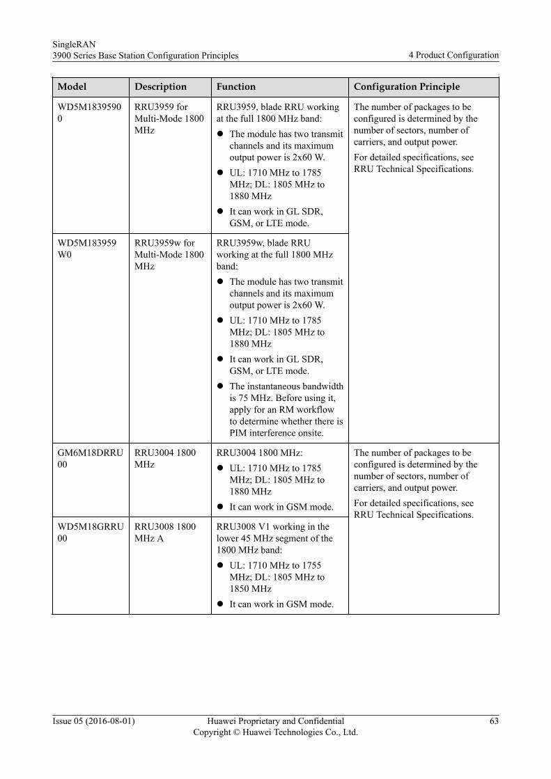
Model Description Function Configuration Principle
WD5M18395900
RRU3959 forMulti-Mode 1800MHz
RRU3959, blade RRU workingat the full 1800 MHz band:l The module has two transmit
channels and its maximumoutput power is 2x60 W.
l UL: 1710 MHz to 1785MHz; DL: 1805 MHz to1880 MHz
l It can work in GL SDR,GSM, or LTE mode.
The number of packages to beconfigured is determined by thenumber of sectors, number ofcarriers, and output power.For detailed specifications, seeRRU Technical Specifications.
WD5M183959W0
RRU3959w forMulti-Mode 1800MHz
RRU3959w, blade RRUworking at the full 1800 MHzband:l The module has two transmit
channels and its maximumoutput power is 2x60 W.
l UL: 1710 MHz to 1785MHz; DL: 1805 MHz to1880 MHz
l It can work in GL SDR,GSM, or LTE mode.
l The instantaneous bandwidthis 75 MHz. Before using it,apply for an RM workflowto determine whether there isPIM interference onsite.
GM6M18DRRU00
RRU3004 1800MHz
RRU3004 1800 MHz:l UL: 1710 MHz to 1785
MHz; DL: 1805 MHz to1880 MHz
l It can work in GSM mode.
The number of packages to beconfigured is determined by thenumber of sectors, number ofcarriers, and output power.For detailed specifications, seeRRU Technical Specifications.
WD5M18GRRU00
RRU3008 1800MHz A
RRU3008 V1 working in thelower 45 MHz segment of the1800 MHz band:l UL: 1710 MHz to 1755
MHz; DL: 1805 MHz to1850 MHz
l It can work in GSM mode.
SingleRAN3900 Series Base Station Configuration Principles 4 Product Configuration
Issue 05 (2016-08-01) Huawei Proprietary and ConfidentialCopyright © Huawei Technologies Co., Ltd.
63
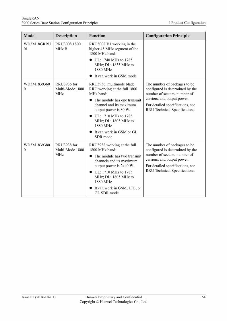
Model Description Function Configuration Principle
WD5M18GRRU01
RRU3008 1800MHz B
RRU3008 V1 working in thehigher 45 MHz segment of the1800 MHz band:l UL: 1740 MHz to 1785
MHz; DL: 1835 MHz to1880 MHz
l It can work in GSM mode.
WD5M18393600
RRU3936 forMulti-Mode 1800MHz
RRU3936, multimode bladeRRU working at the full 1800MHz band:l The module has one transmit
channel and its maximumoutput power is 80 W.
l UL: 1710 MHz to 1785MHz; DL: 1805 MHz to1880 MHz
l It can work in GSM or GLSDR mode.
The number of packages to beconfigured is determined by thenumber of sectors, number ofcarriers, and output power.For detailed specifications, seeRRU Technical Specifications.
WD5M18393800
RRU3938 forMulti-Mode 1800MHz
RRU3938 working at the full1800 MHz band:l The module has two transmit
channels and its maximumoutput power is 2x40 W.
l UL: 1710 MHz to 1785MHz; DL: 1805 MHz to1880 MHz
l It can work in GSM, LTE, orGL SDR mode.
The number of packages to beconfigured is determined by thenumber of sectors, number ofcarriers, and output power.For detailed specifications, seeRRU Technical Specifications.
SingleRAN3900 Series Base Station Configuration Principles 4 Product Configuration
Issue 05 (2016-08-01) Huawei Proprietary and ConfidentialCopyright © Huawei Technologies Co., Ltd.
64
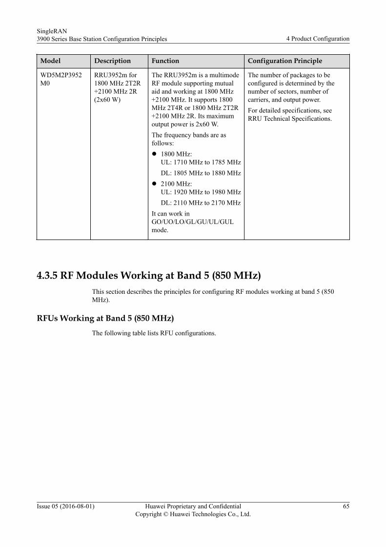
Model Description Function Configuration Principle
WD5M2P3952M0
RRU3952m for1800 MHz 2T2R+2100 MHz 2R(2x60 W)
The RRU3952m is a multimodeRF module supporting mutualaid and working at 1800 MHz+2100 MHz. It supports 1800MHz 2T4R or 1800 MHz 2T2R+2100 MHz 2R. Its maximumoutput power is 2x60 W.The frequency bands are asfollows:l 1800 MHz:
UL: 1710 MHz to 1785 MHzDL: 1805 MHz to 1880 MHz
l 2100 MHz:UL: 1920 MHz to 1980 MHzDL: 2110 MHz to 2170 MHz
It can work inGO/UO/LO/GL/GU/UL/GULmode.
The number of packages to beconfigured is determined by thenumber of sectors, number ofcarriers, and output power.For detailed specifications, seeRRU Technical Specifications.
4.3.5 RF Modules Working at Band 5 (850 MHz)This section describes the principles for configuring RF modules working at band 5 (850MHz).
RFUs Working at Band 5 (850 MHz)The following table lists RFU configurations.
SingleRAN3900 Series Base Station Configuration Principles 4 Product Configuration
Issue 05 (2016-08-01) Huawei Proprietary and ConfidentialCopyright © Huawei Technologies Co., Ltd.
65
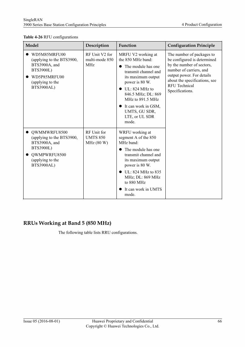
Table 4-26 RFU configurations
Model Description Function Configuration Principle
l WD5M85MRFU00(applying to the BTS3900,BTS3900A, andBTS3900L)
l WD5P85MRFU00(applying to theBTS3900AL)
RF Unit V2 formulti-mode 850MHz
MRFU V2 working atthe 850 MHz band:l The module has one
transmit channel andits maximum outputpower is 80 W.
l UL: 824 MHz to846.5 MHz; DL: 869MHz to 891.5 MHz
l It can work in GSM,UMTS, GU SDR,LTE, or UL SDRmode.
The number of packages tobe configured is determinedby the number of sectors,number of carriers, andoutput power. For detailsabout the specifications, seeRFU TechnicalSpecifications.
l QWMMWRFU8500(applying to the BTS3900,BTS3900A, andBTS3900L)
l QWMPWRFU8500(applying to theBTS3900AL)
RF Unit forUMTS 850MHz (80 W)
WRFU working atsegment A of the 850MHz band:l The module has one
transmit channel andits maximum outputpower is 80 W.
l UL: 824 MHz to 835MHz; DL: 869 MHzto 880 MHz
l It can work in UMTSmode.
RRUs Working at Band 5 (850 MHz)The following table lists RRU configurations.
SingleRAN3900 Series Base Station Configuration Principles 4 Product Configuration
Issue 05 (2016-08-01) Huawei Proprietary and ConfidentialCopyright © Huawei Technologies Co., Ltd.
66
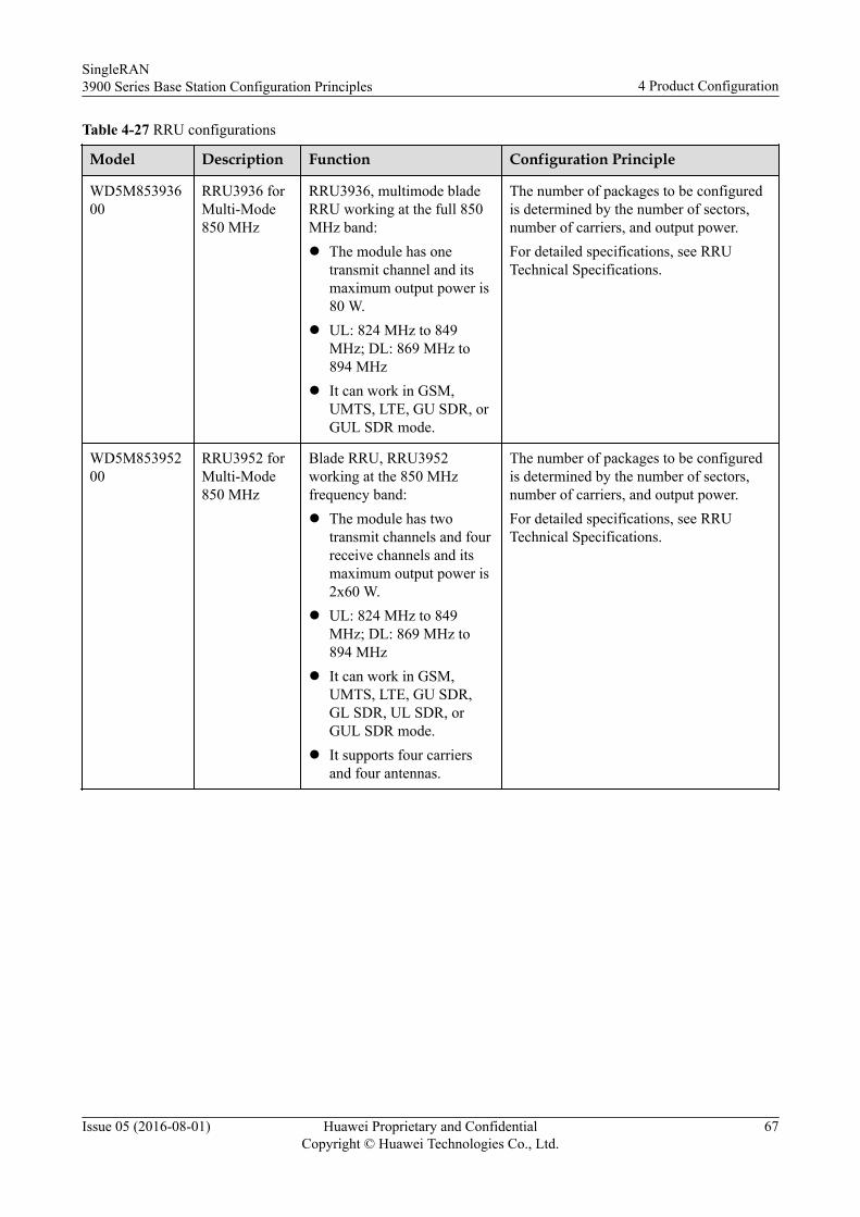
Table 4-27 RRU configurations
Model Description Function Configuration Principle
WD5M85393600
RRU3936 forMulti-Mode850 MHz
RRU3936, multimode bladeRRU working at the full 850MHz band:l The module has one
transmit channel and itsmaximum output power is80 W.
l UL: 824 MHz to 849MHz; DL: 869 MHz to894 MHz
l It can work in GSM,UMTS, LTE, GU SDR, orGUL SDR mode.
The number of packages to be configuredis determined by the number of sectors,number of carriers, and output power.For detailed specifications, see RRUTechnical Specifications.
WD5M85395200
RRU3952 forMulti-Mode850 MHz
Blade RRU, RRU3952working at the 850 MHzfrequency band:l The module has two
transmit channels and fourreceive channels and itsmaximum output power is2x60 W.
l UL: 824 MHz to 849MHz; DL: 869 MHz to894 MHz
l It can work in GSM,UMTS, LTE, GU SDR,GL SDR, UL SDR, orGUL SDR mode.
l It supports four carriersand four antennas.
The number of packages to be configuredis determined by the number of sectors,number of carriers, and output power.For detailed specifications, see RRUTechnical Specifications.
SingleRAN3900 Series Base Station Configuration Principles 4 Product Configuration
Issue 05 (2016-08-01) Huawei Proprietary and ConfidentialCopyright © Huawei Technologies Co., Ltd.
67
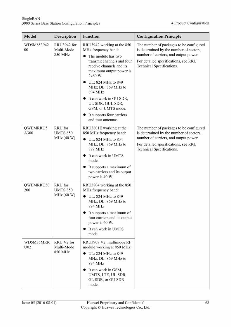
Model Description Function Configuration Principle
WD5M85394200
RRU3942 forMulti-Mode850 MHz
RRU3942 working at the 850MHz frequency band:l The module has two
transmit channels and fourreceive channels and itsmaximum output power is2x60 W.
l UL: 824 MHz to 849MHz; DL: 869 MHz to894 MHz
l It can work in GU SDR,UL SDR, GUL SDR,GSM, or UMTS mode.
l It supports four carriersand four antennas.
The number of packages to be configuredis determined by the number of sectors,number of carriers, and output power.For detailed specifications, see RRUTechnical Specifications.
QWEMRRU5A300
RRU forUMTS 850MHz (40 W)
RRU3801E working at the850 MHz frequency band:l UL: 824 MHz to 834
MHz; DL: 869 MHz to879 MHz
l It can work in UMTSmode.
l It supports a maximum oftwo carriers and its outputpower is 40 W.
The number of packages to be configuredis determined by the number of sectors,number of carriers, and output power.For detailed specifications, see RRUTechnical Specifications.
QWEMRRU50200
RRU forUMTS 850MHz (60 W)
RRU3804 working at the 850MHz frequency band:l UL: 824 MHz to 849
MHz; DL: 869 MHz to894 MHz
l It supports a maximum offour carriers and its outputpower is 60 W.
l It can work in UMTSmode.
WD5M85MRRU02
RRU V2 forMulti-Mode850 MHz
RRU3908 V2, multimode RFmodule working at 850 MHz:l UL: 824 MHz to 849
MHz; DL: 869 MHz to894 MHz
l It can work in GSM,UMTS, LTE, UL SDR,GL SDR, or GU SDRmode.
SingleRAN3900 Series Base Station Configuration Principles 4 Product Configuration
Issue 05 (2016-08-01) Huawei Proprietary and ConfidentialCopyright © Huawei Technologies Co., Ltd.
68
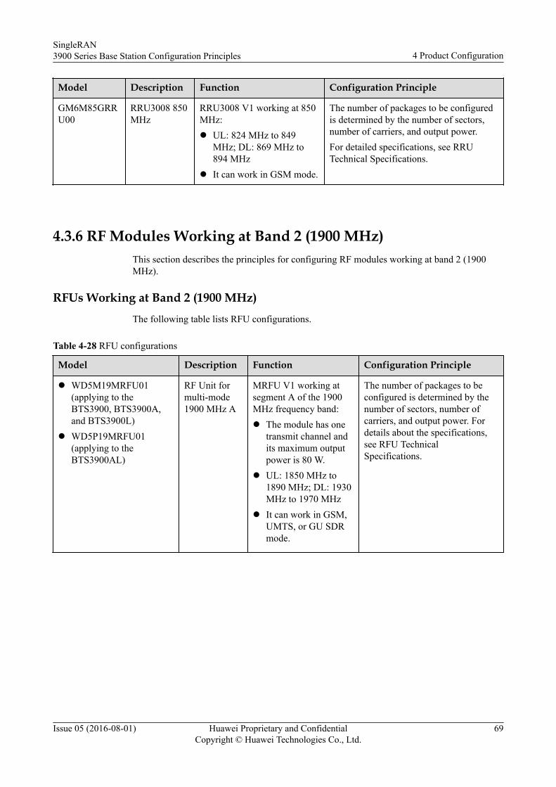
Model Description Function Configuration Principle
GM6M85GRRU00
RRU3008 850MHz
RRU3008 V1 working at 850MHz:l UL: 824 MHz to 849
MHz; DL: 869 MHz to894 MHz
l It can work in GSM mode.
The number of packages to be configuredis determined by the number of sectors,number of carriers, and output power.For detailed specifications, see RRUTechnical Specifications.
4.3.6 RF Modules Working at Band 2 (1900 MHz)This section describes the principles for configuring RF modules working at band 2 (1900MHz).
RFUs Working at Band 2 (1900 MHz)The following table lists RFU configurations.
Table 4-28 RFU configurations
Model Description Function Configuration Principle
l WD5M19MRFU01(applying to theBTS3900, BTS3900A,and BTS3900L)
l WD5P19MRFU01(applying to theBTS3900AL)
RF Unit formulti-mode1900 MHz A
MRFU V1 working atsegment A of the 1900MHz frequency band:l The module has one
transmit channel andits maximum outputpower is 80 W.
l UL: 1850 MHz to1890 MHz; DL: 1930MHz to 1970 MHz
l It can work in GSM,UMTS, or GU SDRmode.
The number of packages to beconfigured is determined by thenumber of sectors, number ofcarriers, and output power. Fordetails about the specifications,see RFU TechnicalSpecifications.
SingleRAN3900 Series Base Station Configuration Principles 4 Product Configuration
Issue 05 (2016-08-01) Huawei Proprietary and ConfidentialCopyright © Huawei Technologies Co., Ltd.
69
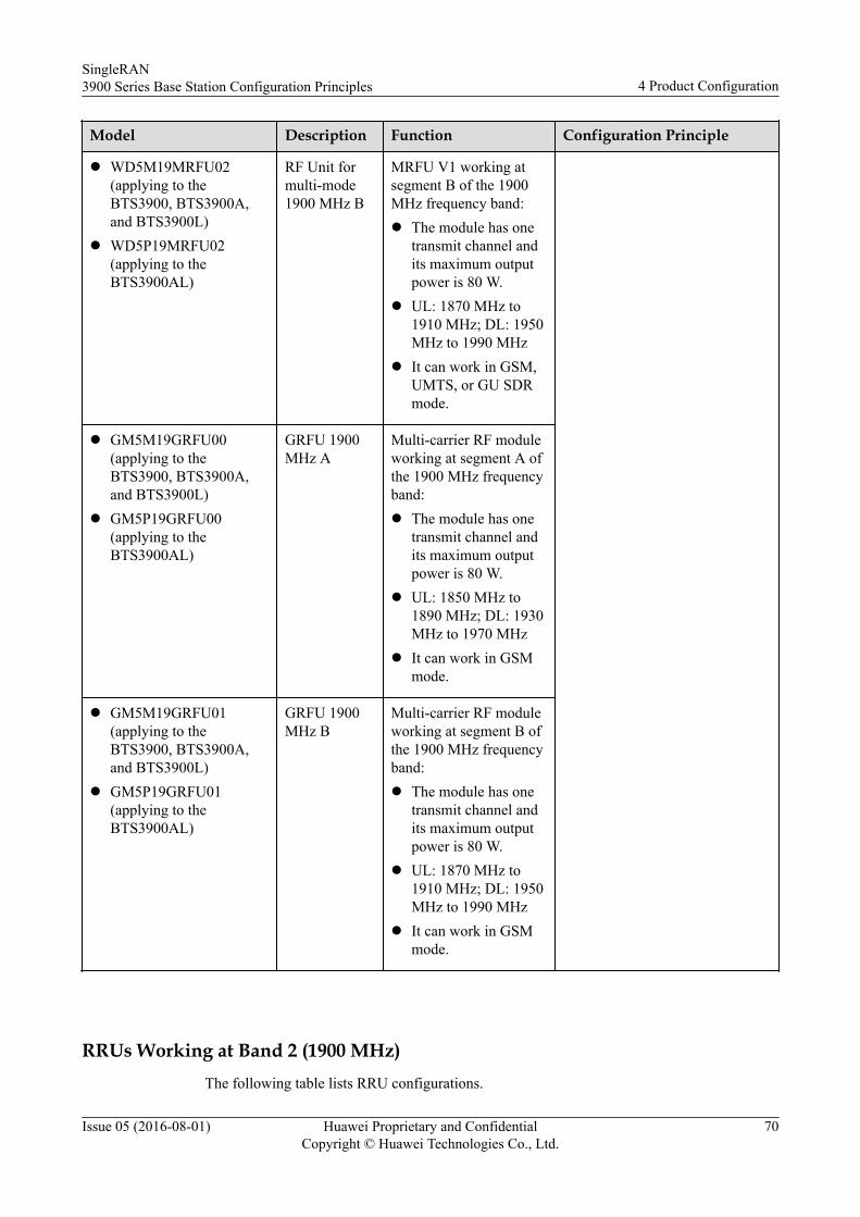
Model Description Function Configuration Principle
l WD5M19MRFU02(applying to theBTS3900, BTS3900A,and BTS3900L)
l WD5P19MRFU02(applying to theBTS3900AL)
RF Unit formulti-mode1900 MHz B
MRFU V1 working atsegment B of the 1900MHz frequency band:l The module has one
transmit channel andits maximum outputpower is 80 W.
l UL: 1870 MHz to1910 MHz; DL: 1950MHz to 1990 MHz
l It can work in GSM,UMTS, or GU SDRmode.
l GM5M19GRFU00(applying to theBTS3900, BTS3900A,and BTS3900L)
l GM5P19GRFU00(applying to theBTS3900AL)
GRFU 1900MHz A
Multi-carrier RF moduleworking at segment A ofthe 1900 MHz frequencyband:l The module has one
transmit channel andits maximum outputpower is 80 W.
l UL: 1850 MHz to1890 MHz; DL: 1930MHz to 1970 MHz
l It can work in GSMmode.
l GM5M19GRFU01(applying to theBTS3900, BTS3900A,and BTS3900L)
l GM5P19GRFU01(applying to theBTS3900AL)
GRFU 1900MHz B
Multi-carrier RF moduleworking at segment B ofthe 1900 MHz frequencyband:l The module has one
transmit channel andits maximum outputpower is 80 W.
l UL: 1870 MHz to1910 MHz; DL: 1950MHz to 1990 MHz
l It can work in GSMmode.
RRUs Working at Band 2 (1900 MHz)The following table lists RRU configurations.
SingleRAN3900 Series Base Station Configuration Principles 4 Product Configuration
Issue 05 (2016-08-01) Huawei Proprietary and ConfidentialCopyright © Huawei Technologies Co., Ltd.
70
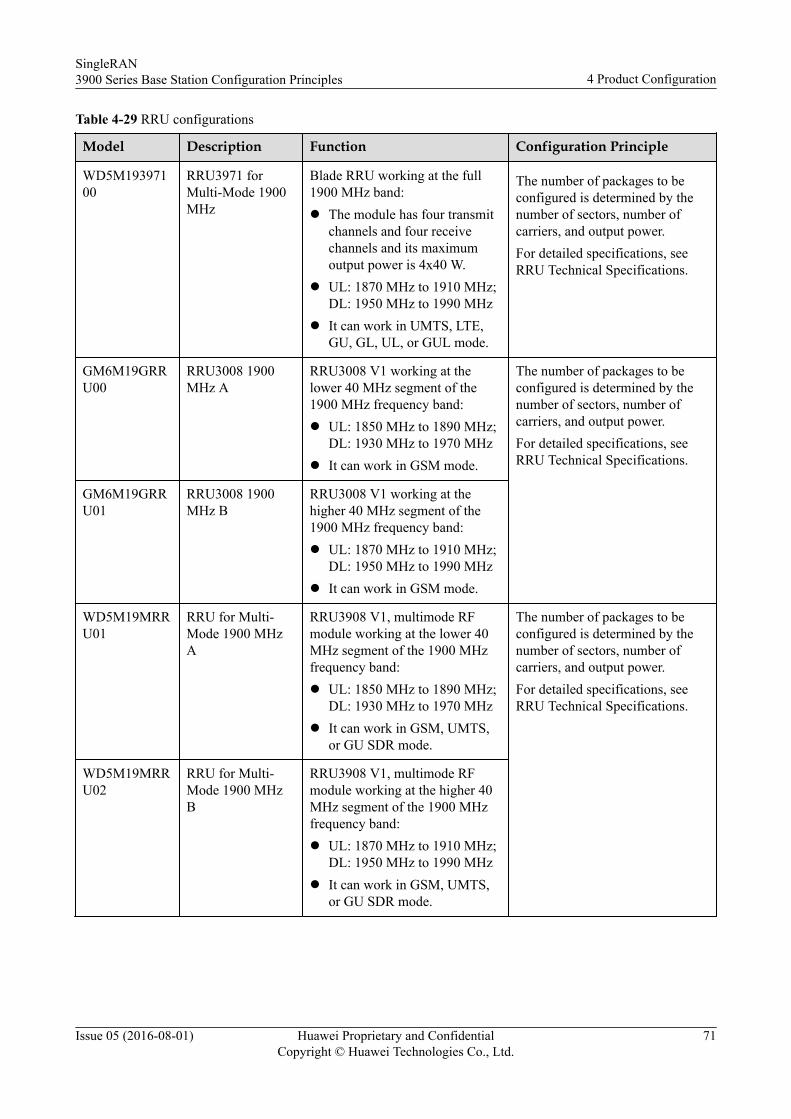
Table 4-29 RRU configurations
Model Description Function Configuration Principle
WD5M19397100
RRU3971 forMulti-Mode 1900MHz
Blade RRU working at the full1900 MHz band:l The module has four transmit
channels and four receivechannels and its maximumoutput power is 4x40 W.
l UL: 1870 MHz to 1910 MHz;DL: 1950 MHz to 1990 MHz
l It can work in UMTS, LTE,GU, GL, UL, or GUL mode.
The number of packages to beconfigured is determined by thenumber of sectors, number ofcarriers, and output power.For detailed specifications, seeRRU Technical Specifications.
GM6M19GRRU00
RRU3008 1900MHz A
RRU3008 V1 working at thelower 40 MHz segment of the1900 MHz frequency band:l UL: 1850 MHz to 1890 MHz;
DL: 1930 MHz to 1970 MHzl It can work in GSM mode.
The number of packages to beconfigured is determined by thenumber of sectors, number ofcarriers, and output power.For detailed specifications, seeRRU Technical Specifications.
GM6M19GRRU01
RRU3008 1900MHz B
RRU3008 V1 working at thehigher 40 MHz segment of the1900 MHz frequency band:l UL: 1870 MHz to 1910 MHz;
DL: 1950 MHz to 1990 MHzl It can work in GSM mode.
WD5M19MRRU01
RRU for Multi-Mode 1900 MHzA
RRU3908 V1, multimode RFmodule working at the lower 40MHz segment of the 1900 MHzfrequency band:l UL: 1850 MHz to 1890 MHz;
DL: 1930 MHz to 1970 MHzl It can work in GSM, UMTS,
or GU SDR mode.
The number of packages to beconfigured is determined by thenumber of sectors, number ofcarriers, and output power.For detailed specifications, seeRRU Technical Specifications.
WD5M19MRRU02
RRU for Multi-Mode 1900 MHzB
RRU3908 V1, multimode RFmodule working at the higher 40MHz segment of the 1900 MHzfrequency band:l UL: 1870 MHz to 1910 MHz;
DL: 1950 MHz to 1990 MHzl It can work in GSM, UMTS,
or GU SDR mode.
SingleRAN3900 Series Base Station Configuration Principles 4 Product Configuration
Issue 05 (2016-08-01) Huawei Proprietary and ConfidentialCopyright © Huawei Technologies Co., Ltd.
71
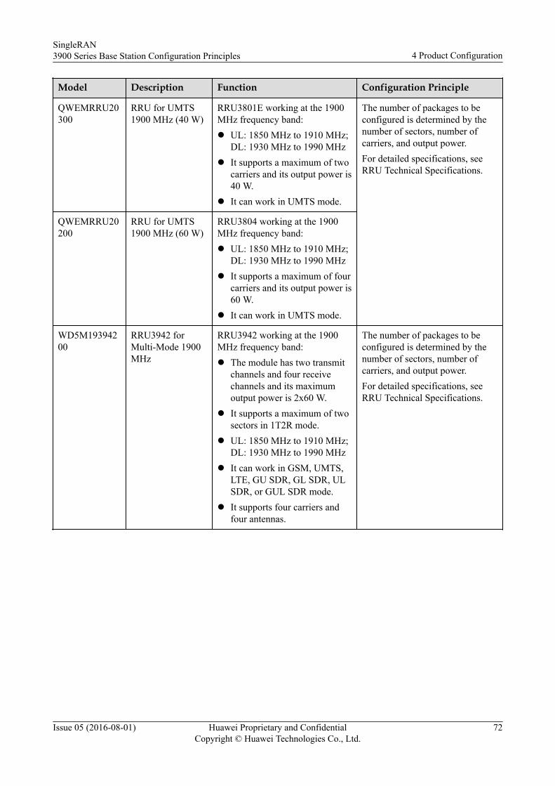
Model Description Function Configuration Principle
QWEMRRU20300
RRU for UMTS1900 MHz (40 W)
RRU3801E working at the 1900MHz frequency band:l UL: 1850 MHz to 1910 MHz;
DL: 1930 MHz to 1990 MHzl It supports a maximum of two
carriers and its output power is40 W.
l It can work in UMTS mode.
The number of packages to beconfigured is determined by thenumber of sectors, number ofcarriers, and output power.For detailed specifications, seeRRU Technical Specifications.
QWEMRRU20200
RRU for UMTS1900 MHz (60 W)
RRU3804 working at the 1900MHz frequency band:l UL: 1850 MHz to 1910 MHz;
DL: 1930 MHz to 1990 MHzl It supports a maximum of four
carriers and its output power is60 W.
l It can work in UMTS mode.
WD5M19394200
RRU3942 forMulti-Mode 1900MHz
RRU3942 working at the 1900MHz frequency band:l The module has two transmit
channels and four receivechannels and its maximumoutput power is 2x60 W.
l It supports a maximum of twosectors in 1T2R mode.
l UL: 1850 MHz to 1910 MHz;DL: 1930 MHz to 1990 MHz
l It can work in GSM, UMTS,LTE, GU SDR, GL SDR, ULSDR, or GUL SDR mode.
l It supports four carriers andfour antennas.
The number of packages to beconfigured is determined by thenumber of sectors, number ofcarriers, and output power.For detailed specifications, seeRRU Technical Specifications.
SingleRAN3900 Series Base Station Configuration Principles 4 Product Configuration
Issue 05 (2016-08-01) Huawei Proprietary and ConfidentialCopyright © Huawei Technologies Co., Ltd.
72
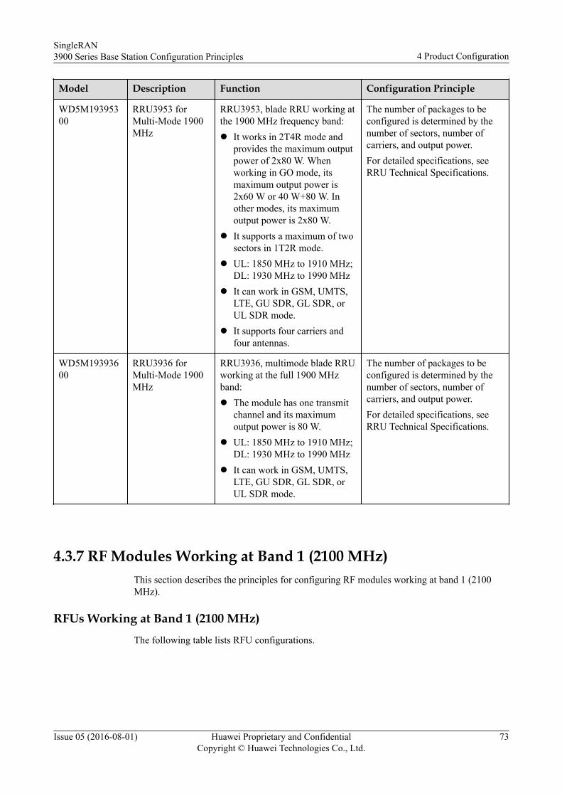
Model Description Function Configuration Principle
WD5M19395300
RRU3953 forMulti-Mode 1900MHz
RRU3953, blade RRU working atthe 1900 MHz frequency band:l It works in 2T4R mode and
provides the maximum outputpower of 2x80 W. Whenworking in GO mode, itsmaximum output power is2x60 W or 40 W+80 W. Inother modes, its maximumoutput power is 2x80 W.
l It supports a maximum of twosectors in 1T2R mode.
l UL: 1850 MHz to 1910 MHz;DL: 1930 MHz to 1990 MHz
l It can work in GSM, UMTS,LTE, GU SDR, GL SDR, orUL SDR mode.
l It supports four carriers andfour antennas.
The number of packages to beconfigured is determined by thenumber of sectors, number ofcarriers, and output power.For detailed specifications, seeRRU Technical Specifications.
WD5M19393600
RRU3936 forMulti-Mode 1900MHz
RRU3936, multimode blade RRUworking at the full 1900 MHzband:l The module has one transmit
channel and its maximumoutput power is 80 W.
l UL: 1850 MHz to 1910 MHz;DL: 1930 MHz to 1990 MHz
l It can work in GSM, UMTS,LTE, GU SDR, GL SDR, orUL SDR mode.
The number of packages to beconfigured is determined by thenumber of sectors, number ofcarriers, and output power.For detailed specifications, seeRRU Technical Specifications.
4.3.7 RF Modules Working at Band 1 (2100 MHz)This section describes the principles for configuring RF modules working at band 1 (2100MHz).
RFUs Working at Band 1 (2100 MHz)The following table lists RFU configurations.
SingleRAN3900 Series Base Station Configuration Principles 4 Product Configuration
Issue 05 (2016-08-01) Huawei Proprietary and ConfidentialCopyright © Huawei Technologies Co., Ltd.
73
Table 4-30 RFU configurations
Model Description Function Configuration Principle
WD5M21MRFUC00 MRFUc forWCDMA 2100MHz (2x60 W)
RF module working atthe 2100 MHz frequencyband:l The module has two
transmit channels andits maximum outputpower is 2x60 W.
l UL: 1920 MHz to1980 MHz; DL: 2110MHz to 2170 MHz
l It can work in UMTS,LTE, or UL SDRmode.
The number of packages tobe configured is determinedby the number of sectors,number of carriers, andoutput power. For detailsabout the specifications, seeRFU TechnicalSpecifications.
WD5M21MRFU01 MRFUd forWCDMA 2100MHz (2x80 W)
RF module working atthe 2100 MHz frequencyband:l The module has two
transmit channels andits maximum outputpower is 2x80 W.
l UL: 1920 MHz to1980 MHz; DL: 2110MHz to 2170 MHz
l It can work in UMTS,LTE, or UL SDRmode.
l QWMMWRFUA100(applying to the BTS3900,BTS3900A, andBTS3900L)
l QWMPWRFUA100(applying to theBTS3900AL)
WRFUa forWCDMA 2100MHz (1x100 W)
RF module working atthe 2100 MHz frequencyband:l The module has one
transmit channel andits maximum outputpower is 100 W.
l UL: 1920 MHz to1980 MHz; DL: 2110MHz to 2170 MHz
l It can work in UMTSmode.
The number of packages tobe configured is determinedby the number of sectors,number of carriers, andoutput power. For detailsabout the specifications, seeRFU TechnicalSpecifications.
SingleRAN3900 Series Base Station Configuration Principles 4 Product Configuration
Issue 05 (2016-08-01) Huawei Proprietary and ConfidentialCopyright © Huawei Technologies Co., Ltd.
74
Model Description Function Configuration Principle
l WD5MIFUHA100(applying to the BTS3900,BTS3900A, andBTS3900L)
l
l WD5PIFUH8101l (applying to the
BTS3900AL)
WRFUa V6 forWCDMA 2100MHz (1x100 W)
RF module working atthe 2100 MHz frequencyband:l The module has one
transmit channel andits maximum outputpower is 100 W.
l UL: 1920 MHz to1980 MHz; DL: 2110MHz to 2170 MHz
l It can work in UMTSmode.
It supports a maximum offour carriers.
l QWMMWRFU8101(applying to the BTS3900,BTS3900A, andBTS3900L)
l QWMPWRFU2100(applying to theBTS3900AL)
WRFUe forWCDMA 2100MHz (2x80 W)
RF module working atthe 2100 MHz frequencyband:l The module has two
transmit channels andits maximum outputpower is 2x80 W.
l UL: 1920 MHz to1980 MHz; DL: 2110MHz to 2170 MHz
l It can work in UMTSmode.
l QWMMWRFU6100(applying to the BTS3900,BTS3900A, andBTS3900L)
l QWMPWRFU6100(applying to theBTS3900AL)
WRFUd forWCDMA 2100MHz (2x60 W)
RF module working atthe 2100 MHz frequencyband:l The module has two
transmit channels andits maximum outputpower is 2x60 W.
l UL: 1920 MHz to1980 MHz; DL: 2110MHz to 2170 MHz
l It can work in UMTSmode.
SingleRAN3900 Series Base Station Configuration Principles 4 Product Configuration
Issue 05 (2016-08-01) Huawei Proprietary and ConfidentialCopyright © Huawei Technologies Co., Ltd.
75
Model Description Function Configuration Principle
l QWMMWRFU8102(applying to the BTS3900,BTS3900A, andBTS3900L)
l QWMPWRFU1101(applying to theBTS3900AL)
RF Unit forWCDMA 2100MHz (80 W)
RF module working atthe 2100 MHz frequencyband (enhanced moduleof the WRFU whoseoutput power is 80 W):l The module has one
transmit channel andits maximum outputpower is 80 W.
l UL: 1920 MHz to1980 MHz; DL: 2110MHz to 2170 MHz
l It can work in UMTSmode.
l QWMMWRFU4100(applying to the BTS3900,BTS3900A, andBTS3900L)
l QWMPWRFU4100(applying to theBTS3900AL)
RF Unit forWCDMA 2100MHz (40 W)
RF module working atthe 2100 MHz frequencyband:l The module has one
transmit channel andits maximum outputpower is 40 W.
l UL: 1920 MHz to1980 MHz; DL: 2110MHz to 2170 MHz
l It can work in UMTSmode.
l QWMMWRFU8100(applying to the BTS3900,BTS3900A, andBTS3900L)
l QWMPWRFU8100(applying to theBTS3900AL)
RF Unit forWCDMA 2100MHz (80 W)
RF module working atthe 2100 MHz frequencyband:l The module has one
transmit channel andits maximum outputpower is 80 W.
l UL: 1920 MHz to1980 MHz; DL: 2110MHz to 2170 MHz
l It can work in UMTSmode.
RRUs Working at Band 1 (2100 MHz)
The following table lists RRU configurations.
SingleRAN3900 Series Base Station Configuration Principles 4 Product Configuration
Issue 05 (2016-08-01) Huawei Proprietary and ConfidentialCopyright © Huawei Technologies Co., Ltd.
76
Table 4-31 RRU configurations
Model Description Function Configuration Principle
WD5M21395200
RRU3952 formultimode 2100MHz
RRU3952, blade RRU workingat the full 2100 MHz band:l The module has two
transmit channels and itsmaximum output power is2x60 W.
l UL: 1920 MHz to 1980MHz; DL: 2110 MHz to2170 MHz
l It can work in UMTS, LTE,or UL SDR mode.
The number of packages to beconfigured is determined by thenumber of sectors, number ofcarriers, and output power.For detailed specifications, seeRRU Technical Specifications.
WD5M21395800
RRU3958 formultimode 2100MHz
RRU3958, blade RRU workingat the full 2100 MHz band:l The module has two
transmit channels and itsmaximum output power is2x40 W.
l UL: 1920 MHz to 1980MHz; DL: 2110 MHz to2170 MHz
l It can work in UMTS, LTE,or UL SDR mode.
WD5M21397100
RRU3971 formultimode 2100MHz
RRU3971, blade RRU workingat the full 2100 MHz band:l The module has four
transmit channels and fourreceive channels and itsmaximum output power is4x40 W.
l UL: 1920 MHz to 1980MHz; DL: 2110 MHz to2170 MHz
l It can work in UMTS, LTE,or UL SDR mode.
The number of packages to beconfigured is determined by thenumber of sectors, number ofcarriers, and output power.For detailed specifications, seeRRU Technical Specifications.
SingleRAN3900 Series Base Station Configuration Principles 4 Product Configuration
Issue 05 (2016-08-01) Huawei Proprietary and ConfidentialCopyright © Huawei Technologies Co., Ltd.
77
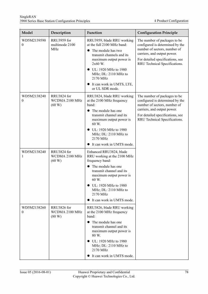
Model Description Function Configuration Principle
WD5M21395900
RRU3959 formultimode 2100MHz
RRU3959, blade RRU workingat the full 2100 MHz band:l The module has two
transmit channels and itsmaximum output power is2x60 W.
l UL: 1920 MHz to 1980MHz; DL: 2110 MHz to2170 MHz
l It can work in UMTS, LTE,or UL SDR mode.
The number of packages to beconfigured is determined by thenumber of sectors, number ofcarriers, and output power.For detailed specifications, seeRRU Technical Specifications.
WD5M21382400
RRU3824 forWCDMA 2100 MHz(60 W)
RRU3824, blade RRU workingat the 2100 MHz frequencyband:l The module has one
transmit channel and itsmaximum output power is60 W.
l UL: 1920 MHz to 1980MHz; DL: 2110 MHz to2170 MHz
l It can work in UMTS mode.
The number of packages to beconfigured is determined by thenumber of sectors, number ofcarriers, and output power.For detailed specifications, seeRRU Technical Specifications.
WD5M21382401
RRU3824 forWCDMA 2100 MHz(60 W)
Enhanced RRU3824, bladeRRU working at the 2100 MHzfrequency band:l The module has one
transmit channel and itsmaximum output power is60 W.
l UL: 1920 MHz to 1980MHz; DL: 2110 MHz to2170 MHz
l It can work in UMTS mode.
WD5M21382600
RRU3826 forWCDMA 2100 MHz(80 W)
RRU3826, blade RRU workingat the 2100 MHz frequencyband:l The module has one
transmit channel and itsmaximum output power is80 W.
l UL: 1920 MHz to 1980MHz; DL: 2110 MHz to2170 MHz
l It can work in UMTS mode.
SingleRAN3900 Series Base Station Configuration Principles 4 Product Configuration
Issue 05 (2016-08-01) Huawei Proprietary and ConfidentialCopyright © Huawei Technologies Co., Ltd.
78
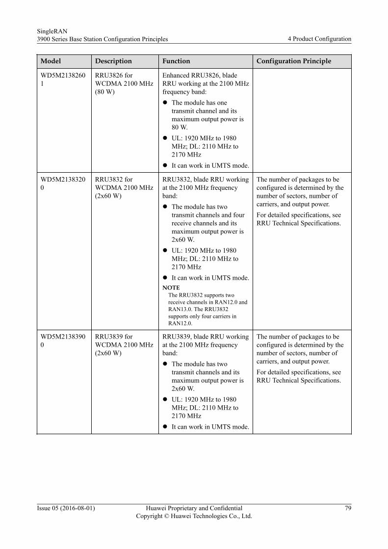
Model Description Function Configuration Principle
WD5M21382601
RRU3826 forWCDMA 2100 MHz(80 W)
Enhanced RRU3826, bladeRRU working at the 2100 MHzfrequency band:l The module has one
transmit channel and itsmaximum output power is80 W.
l UL: 1920 MHz to 1980MHz; DL: 2110 MHz to2170 MHz
l It can work in UMTS mode.
WD5M21383200
RRU3832 forWCDMA 2100 MHz(2x60 W)
RRU3832, blade RRU workingat the 2100 MHz frequencyband:l The module has two
transmit channels and fourreceive channels and itsmaximum output power is2x60 W.
l UL: 1920 MHz to 1980MHz; DL: 2110 MHz to2170 MHz
l It can work in UMTS mode.NOTE
The RRU3832 supports tworeceive channels in RAN12.0 andRAN13.0. The RRU3832supports only four carriers inRAN12.0.
The number of packages to beconfigured is determined by thenumber of sectors, number ofcarriers, and output power.For detailed specifications, seeRRU Technical Specifications.
WD5M21383900
RRU3839 forWCDMA 2100 MHz(2x60 W)
RRU3839, blade RRU workingat the 2100 MHz frequencyband:l The module has two
transmit channels and itsmaximum output power is2x60 W.
l UL: 1920 MHz to 1980MHz; DL: 2110 MHz to2170 MHz
l It can work in UMTS mode.
The number of packages to beconfigured is determined by thenumber of sectors, number ofcarriers, and output power.For detailed specifications, seeRRU Technical Specifications.
SingleRAN3900 Series Base Station Configuration Principles 4 Product Configuration
Issue 05 (2016-08-01) Huawei Proprietary and ConfidentialCopyright © Huawei Technologies Co., Ltd.
79
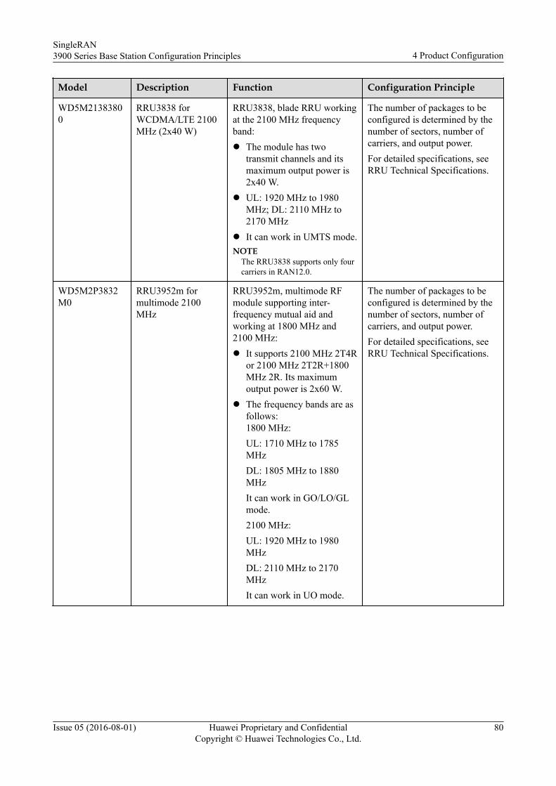
Model Description Function Configuration Principle
WD5M21383800
RRU3838 forWCDMA/LTE 2100MHz (2x40 W)
RRU3838, blade RRU workingat the 2100 MHz frequencyband:l The module has two
transmit channels and itsmaximum output power is2x40 W.
l UL: 1920 MHz to 1980MHz; DL: 2110 MHz to2170 MHz
l It can work in UMTS mode.NOTE
The RRU3838 supports only fourcarriers in RAN12.0.
The number of packages to beconfigured is determined by thenumber of sectors, number ofcarriers, and output power.For detailed specifications, seeRRU Technical Specifications.
WD5M2P3832M0
RRU3952m formultimode 2100MHz
RRU3952m, multimode RFmodule supporting inter-frequency mutual aid andworking at 1800 MHz and2100 MHz:l It supports 2100 MHz 2T4R
or 2100 MHz 2T2R+1800MHz 2R. Its maximumoutput power is 2x60 W.
l The frequency bands are asfollows:1800 MHz:UL: 1710 MHz to 1785MHzDL: 1805 MHz to 1880MHzIt can work in GO/LO/GLmode.2100 MHz:UL: 1920 MHz to 1980MHzDL: 2110 MHz to 2170MHzIt can work in UO mode.
The number of packages to beconfigured is determined by thenumber of sectors, number ofcarriers, and output power.For detailed specifications, seeRRU Technical Specifications.
SingleRAN3900 Series Base Station Configuration Principles 4 Product Configuration
Issue 05 (2016-08-01) Huawei Proprietary and ConfidentialCopyright © Huawei Technologies Co., Ltd.
80
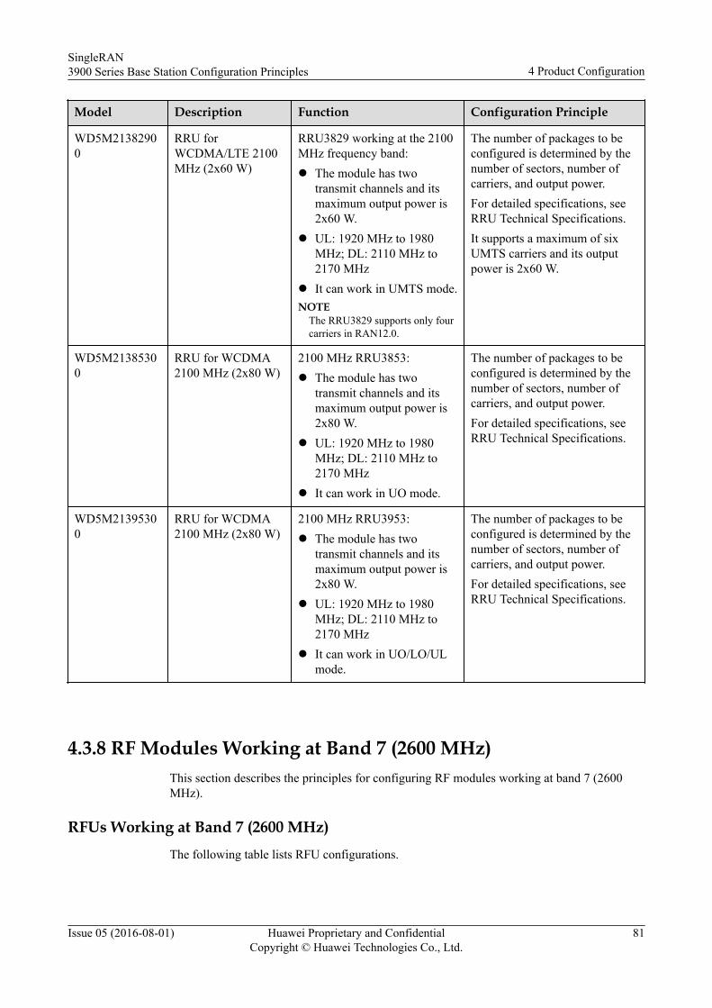
Model Description Function Configuration Principle
WD5M21382900
RRU forWCDMA/LTE 2100MHz (2x60 W)
RRU3829 working at the 2100MHz frequency band:l The module has two
transmit channels and itsmaximum output power is2x60 W.
l UL: 1920 MHz to 1980MHz; DL: 2110 MHz to2170 MHz
l It can work in UMTS mode.NOTE
The RRU3829 supports only fourcarriers in RAN12.0.
The number of packages to beconfigured is determined by thenumber of sectors, number ofcarriers, and output power.For detailed specifications, seeRRU Technical Specifications.It supports a maximum of sixUMTS carriers and its outputpower is 2x60 W.
WD5M21385300
RRU for WCDMA2100 MHz (2x80 W)
2100 MHz RRU3853:l The module has two
transmit channels and itsmaximum output power is2x80 W.
l UL: 1920 MHz to 1980MHz; DL: 2110 MHz to2170 MHz
l It can work in UO mode.
The number of packages to beconfigured is determined by thenumber of sectors, number ofcarriers, and output power.For detailed specifications, seeRRU Technical Specifications.
WD5M21395300
RRU for WCDMA2100 MHz (2x80 W)
2100 MHz RRU3953:l The module has two
transmit channels and itsmaximum output power is2x80 W.
l UL: 1920 MHz to 1980MHz; DL: 2110 MHz to2170 MHz
l It can work in UO/LO/ULmode.
The number of packages to beconfigured is determined by thenumber of sectors, number ofcarriers, and output power.For detailed specifications, seeRRU Technical Specifications.
4.3.8 RF Modules Working at Band 7 (2600 MHz)This section describes the principles for configuring RF modules working at band 7 (2600MHz).
RFUs Working at Band 7 (2600 MHz)The following table lists RFU configurations.
SingleRAN3900 Series Base Station Configuration Principles 4 Product Configuration
Issue 05 (2016-08-01) Huawei Proprietary and ConfidentialCopyright © Huawei Technologies Co., Ltd.
81
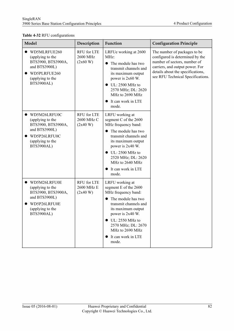
Table 4-32 RFU configurations
Model Description Function Configuration Principle
l WD5MLRFUE260(applying to theBTS3900, BTS3900A,and BTS3900L)
l WD5PLRFUE260(applying to theBTS3900AL)
RFU for LTE2600 MHz(2x60 W)
LRFUe working at 2600MHz:l The module has two
transmit channels andits maximum outputpower is 2x60 W.
l UL: 2500 MHz to2570 MHz; DL: 2620MHz to 2690 MHz
l It can work in LTEmode.
The number of packages to beconfigured is determined by thenumber of sectors, number ofcarriers, and output power. Fordetails about the specifications,see RFU Technical Specifications.
l WD5M26LRFU0C(applying to theBTS3900, BTS3900A,and BTS3900L)
l WD5P26LRFU0C(applying to theBTS3900AL)
RFU for LTE2600 MHz C(2x40 W)
LRFU working atsegment C of the 2600MHz frequency band:l The module has two
transmit channels andits maximum outputpower is 2x40 W.
l UL: 2500 MHz to2520 MHz; DL: 2620MHz to 2640 MHz
l It can work in LTEmode.
l WD5M26LRFU0E(applying to theBTS3900, BTS3900A,and BTS3900L)
l WD5P26LRFU0E(applying to theBTS3900AL)
RFU for LTE2600 MHz E(2x40 W)
LRFU working atsegment E of the 2600MHz frequency band:l The module has two
transmit channels andits maximum outputpower is 2x40 W.
l UL: 2550 MHz to2570 MHz; DL: 2670MHz to 2690 MHz
l It can work in LTEmode.
SingleRAN3900 Series Base Station Configuration Principles 4 Product Configuration
Issue 05 (2016-08-01) Huawei Proprietary and ConfidentialCopyright © Huawei Technologies Co., Ltd.
82
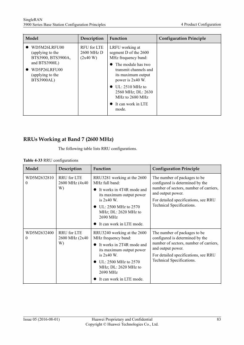
Model Description Function Configuration Principle
l WD5M26LRFU00(applying to theBTS3900, BTS3900A,and BTS3900L)
l WD5P26LRFU00(applying to theBTS3900AL)
RFU for LTE2600 MHz D(2x40 W)
LRFU working atsegment D of the 2600MHz frequency band:l The module has two
transmit channels andits maximum outputpower is 2x40 W.
l UL: 2510 MHz to2560 MHz; DL: 2630MHz to 2680 MHz
l It can work in LTEmode.
RRUs Working at Band 7 (2600 MHz)The following table lists RRU configurations.
Table 4-33 RRU configurations
Model Description Function Configuration Principle
WD5M26328100
RRU for LTE2600 MHz (4x40W)
RRU3281 working at the 2600MHz full band:l It works in 4T4R mode and
its maximum output poweris 2x40 W.
l UL: 2500 MHz to 2570MHz; DL: 2620 MHz to2690 MHz
l It can work in LTE mode.
The number of packages to beconfigured is determined by thenumber of sectors, number of carriers,and output power.For detailed specifications, see RRUTechnical Specifications.
WD5M26324000
RRU for LTE2600 MHz (2x40W)
RRU3240 working at the 2600MHz frequency band:l It works in 2T4R mode and
its maximum output poweris 2x40 W.
l UL: 2500 MHz to 2570MHz; DL: 2620 MHz to2690 MHz
l It can work in LTE mode.
The number of packages to beconfigured is determined by thenumber of sectors, number of carriers,and output power.For detailed specifications, see RRUTechnical Specifications.
SingleRAN3900 Series Base Station Configuration Principles 4 Product Configuration
Issue 05 (2016-08-01) Huawei Proprietary and ConfidentialCopyright © Huawei Technologies Co., Ltd.
83
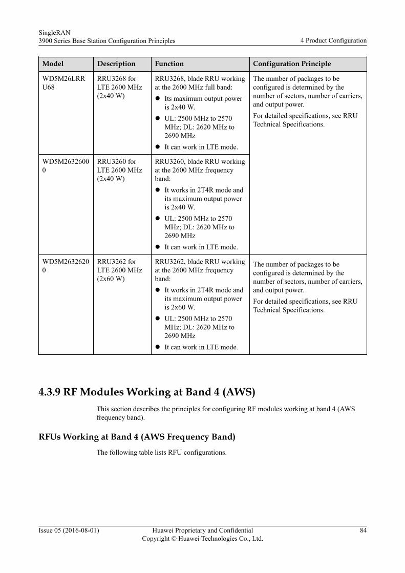
Model Description Function Configuration Principle
WD5M26LRRU68
RRU3268 forLTE 2600 MHz(2x40 W)
RRU3268, blade RRU workingat the 2600 MHz full band:l Its maximum output power
is 2x40 W.l UL: 2500 MHz to 2570
MHz; DL: 2620 MHz to2690 MHz
l It can work in LTE mode.
The number of packages to beconfigured is determined by thenumber of sectors, number of carriers,and output power.For detailed specifications, see RRUTechnical Specifications.
WD5M26326000
RRU3260 forLTE 2600 MHz(2x40 W)
RRU3260, blade RRU workingat the 2600 MHz frequencyband:l It works in 2T4R mode and
its maximum output poweris 2x40 W.
l UL: 2500 MHz to 2570MHz; DL: 2620 MHz to2690 MHz
l It can work in LTE mode.
WD5M26326200
RRU3262 forLTE 2600 MHz(2x60 W)
RRU3262, blade RRU workingat the 2600 MHz frequencyband:l It works in 2T4R mode and
its maximum output poweris 2x60 W.
l UL: 2500 MHz to 2570MHz; DL: 2620 MHz to2690 MHz
l It can work in LTE mode.
The number of packages to beconfigured is determined by thenumber of sectors, number of carriers,and output power.For detailed specifications, see RRUTechnical Specifications.
4.3.9 RF Modules Working at Band 4 (AWS)This section describes the principles for configuring RF modules working at band 4 (AWSfrequency band).
RFUs Working at Band 4 (AWS Frequency Band)The following table lists RFU configurations.
SingleRAN3900 Series Base Station Configuration Principles 4 Product Configuration
Issue 05 (2016-08-01) Huawei Proprietary and ConfidentialCopyright © Huawei Technologies Co., Ltd.
84
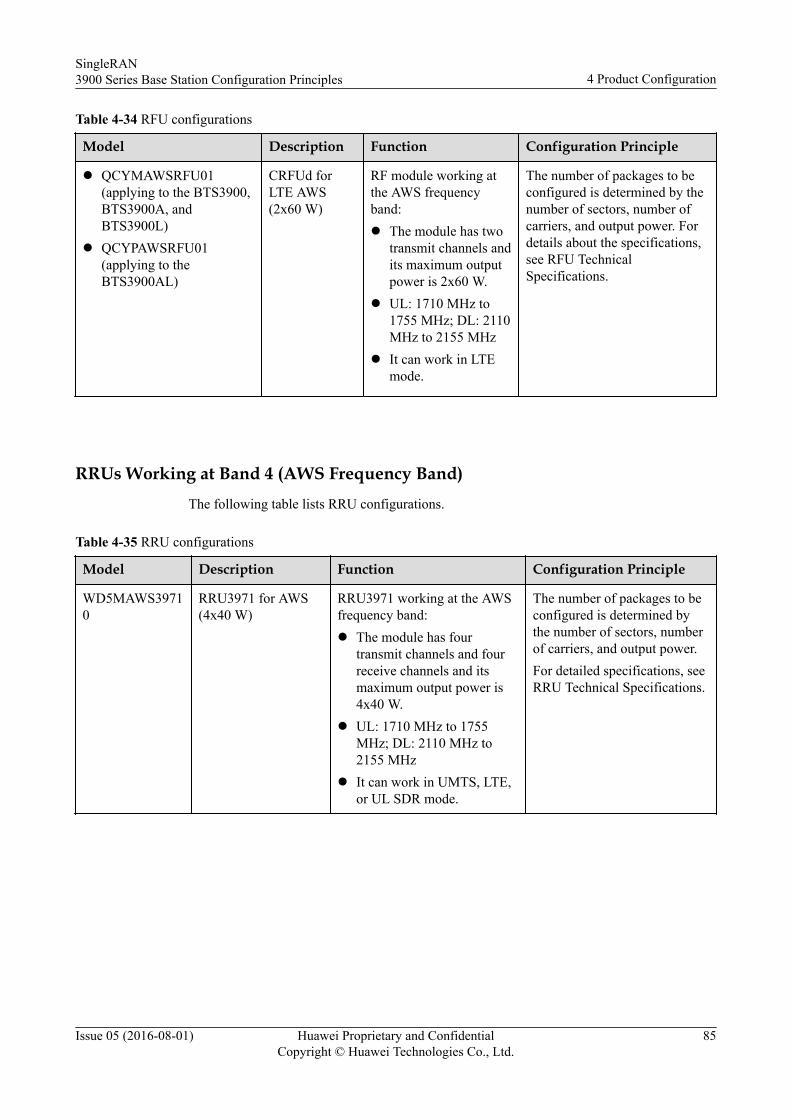
Table 4-34 RFU configurations
Model Description Function Configuration Principle
l QCYMAWSRFU01(applying to the BTS3900,BTS3900A, andBTS3900L)
l QCYPAWSRFU01(applying to theBTS3900AL)
CRFUd forLTE AWS(2x60 W)
RF module working atthe AWS frequencyband:l The module has two
transmit channels andits maximum outputpower is 2x60 W.
l UL: 1710 MHz to1755 MHz; DL: 2110MHz to 2155 MHz
l It can work in LTEmode.
The number of packages to beconfigured is determined by thenumber of sectors, number ofcarriers, and output power. Fordetails about the specifications,see RFU TechnicalSpecifications.
RRUs Working at Band 4 (AWS Frequency Band)The following table lists RRU configurations.
Table 4-35 RRU configurations
Model Description Function Configuration Principle
WD5MAWS39710
RRU3971 for AWS(4x40 W)
RRU3971 working at the AWSfrequency band:l The module has four
transmit channels and fourreceive channels and itsmaximum output power is4x40 W.
l UL: 1710 MHz to 1755MHz; DL: 2110 MHz to2155 MHz
l It can work in UMTS, LTE,or UL SDR mode.
The number of packages to beconfigured is determined bythe number of sectors, numberof carriers, and output power.For detailed specifications, seeRRU Technical Specifications.
SingleRAN3900 Series Base Station Configuration Principles 4 Product Configuration
Issue 05 (2016-08-01) Huawei Proprietary and ConfidentialCopyright © Huawei Technologies Co., Ltd.
85
Model Description Function Configuration Principle
WD5MAW384100
RRU for LTE AWS(4T4R, 2x60 W/4x30W)
RRU3841 working at the AWSfrequency band:l The module has four
transmit channels and fourreceive channels and itsmaximum output power is2x60 W or 4x30 W.
l UL: 1710 MHz to 1755MHz; DL: 2110 MHz to2155 MHz
l It can work in LTE mode.
The number of packages to beconfigured is determined bythe number of sectors, numberof carriers, and output power.For detailed specifications, seeRRU Technical Specifications.
QWEMRRU40800
RRU for UMTS/LTEAWS (2x40 W)
RRU3808 working at the AWSfrequency band:l UL: 1710 MHz to 1755
MHz; DL: 2110 MHz to2155 MHz
l It can work in UMTS, LTE,or UL SDR mode.
The number of packages to beconfigured is determined bythe number of sectors, numberof carriers, and output power.For detailed specifications, seeRRU Technical Specifications.
WD5M21383200 RRU3832 forWCDMA/LTE AWS(2x60 W)
RRU3832, blade RRU workingat the AWS frequency band:l The module has two
transmit channels and fourreceive channels and itsmaximum output power is2x60 W.
l UL: 1710 MHz to 1755MHz; DL: 2110 MHz to2155 MHz
l It can work in UMTS, LTE,or UL SDR mode.
The number of packages to beconfigured is determined bythe number of sectors, numberof carriers, and output power.For detailed specifications, seeRRU Technical Specifications.
4.3.10 RF Modules Working at Band 66 (AWS-3)
RRUs Working at Band 66 (AWS-3)The following table lists RRU configurations.
SingleRAN3900 Series Base Station Configuration Principles 4 Product Configuration
Issue 05 (2016-08-01) Huawei Proprietary and ConfidentialCopyright © Huawei Technologies Co., Ltd.
86
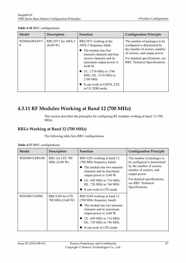
Table 4-36 RRU configurations
Model Description Function Configuration Principle
WD5MAWS39710
RRU3971 for AWS-3(4x40 W)
RRU3971 working at theAWS-3 frequency band:l The module has four
transmit channels and fourreceive channels and itsmaximum output power is4x40 W.
l UL: 1710 MHz to 1780MHz; DL: 2110 MHz to2180 MHz
l It can work in UMTS, LTE,or UL SDR mode.
The number of packages to beconfigured is determined bythe number of sectors, numberof carriers, and output power.For detailed specifications, seeRRU Technical Specifications.
4.3.11 RF Modules Working at Band 12 (700 MHz)This section describes the principles for configuring RF modules working at band 12 (700MHz).
RRUs Working at Band 12 (700 MHz)The following table lists RRU configurations.
Table 4-37 RRU configurations
Model Description Function Configuration Principle
WD5M07LRRU00 RRU for LTE 700MHz (2x40 W)
RRU3203 working at band 12(700 MHz frequency band):l The module has two transmit
channels and its maximumoutput power is 2x40 W.
l UL: 698 MHz to 716 MHz;DL: 728 MHz to 746 MHz
l It can work in LTE mode.
The number of packages tobe configured is determinedby the number of sectors,number of carriers, andoutput power.For detailed specifications,see RRU TechnicalSpecifications.
WD5M07324900 RRU3249 for LTE700 MHz (2x60 W)
RRU3249 working at band 12(700 MHz frequency band):l The module has two transmit
channels and its maximumoutput power is 2x60 W.
l UL: 699 MHz to 716 MHz;DL: 729 MHz to 746 MHz
l It can work in LTE mode.
SingleRAN3900 Series Base Station Configuration Principles 4 Product Configuration
Issue 05 (2016-08-01) Huawei Proprietary and ConfidentialCopyright © Huawei Technologies Co., Ltd.
87
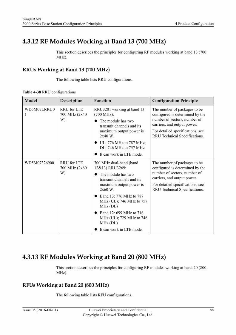
4.3.12 RF Modules Working at Band 13 (700 MHz)This section describes the principles for configuring RF modules working at band 13 (700MHz).
RRUs Working at Band 13 (700 MHz)
The following table lists RRU configurations.
Table 4-38 RRU configurations
Model Description Function Configuration Principle
WD5M07LRRU01
RRU for LTE700 MHz (2x40W)
RRU3201 working at band 13(700 MHz):l The module has two
transmit channels and itsmaximum output power is2x40 W.
l UL: 776 MHz to 787 MHz;DL: 746 MHz to 757 MHz
l It can work in LTE mode.
The number of packages to beconfigured is determined by thenumber of sectors, number ofcarriers, and output power.For detailed specifications, seeRRU Technical Specifications.
WD5M07326900 RRU for LTE700 MHz (2x60W)
700 MHz dual-band (band12&13) RRU3269:l The module has two
transmit channels and itsmaximum output power is2x60 W.
l Band 13: 776 MHz to 787MHz (UL); 746 MHz to 757MHz (DL)
l Band 12: 699 MHz to 716MHz (UL); 729 MHz to 746MHz (DL)
l It can work in LTE mode.
The number of packages to beconfigured is determined by thenumber of sectors, number ofcarriers, and output power.For detailed specifications, seeRRU Technical Specifications.
4.3.13 RF Modules Working at Band 20 (800 MHz)This section describes the principles for configuring RF modules working at band 20 (800MHz).
RFUs Working at Band 20 (800 MHz)
The following table lists RFU configurations.
SingleRAN3900 Series Base Station Configuration Principles 4 Product Configuration
Issue 05 (2016-08-01) Huawei Proprietary and ConfidentialCopyright © Huawei Technologies Co., Ltd.
88
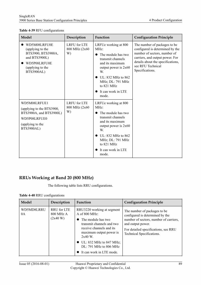
Table 4-39 RFU configurations
Model Description Function Configuration Principle
l WD5M08LRFU0E(applying to theBTS3900, BTS3900A,and BTS3900L)
l WD5P08LRFU0E(applying to theBTS3900AL)
LRFU for LTE800 MHz (2x60W)
LRFUe working at 800MHz:l The module has two
transmit channelsand its maximumoutput power is 2x60W.
l UL: 832 MHz to 862MHz; DL: 791 MHzto 821 MHz
l It can work in LTEmode.
The number of packages to beconfigured is determined by thenumber of sectors, number ofcarriers, and output power. Fordetails about the specifications,see RFU TechnicalSpecifications.
WD5M08LRFUE1(applying to the BTS3900,BTS3900A, and BTS3900L)WD5P08LRFUE0(applying to theBTS3900AL)
LRFU for LTE800 MHz (2x60W)
LRFUe working at 800MHz:l The module has two
transmit channelsand its maximumoutput power is 2x60W.
l UL: 832 MHz to 862MHz; DL: 791 MHzto 821 MHz
l It can work in LTEmode.
RRUs Working at Band 20 (800 MHz)
The following table lists RRU configurations.
Table 4-40 RRU configurations
Model Description Function Configuration Principle
WD5MD8LRRU0A
RRU for LTE800 MHz A(2x40 W)
RRU3220 working at segmentA of 800 MHz:l The module has two
transmit channels and tworeceive channels and itsmaximum output power is2x40 W.
l UL: 832 MHz to 847 MHz;DL: 791 MHz to 806 MHz
l It can work in LTE mode.
The number of packages to beconfigured is determined by thenumber of sectors, number of carriers,and output power.For detailed specifications, see RRUTechnical Specifications.
SingleRAN3900 Series Base Station Configuration Principles 4 Product Configuration
Issue 05 (2016-08-01) Huawei Proprietary and ConfidentialCopyright © Huawei Technologies Co., Ltd.
89
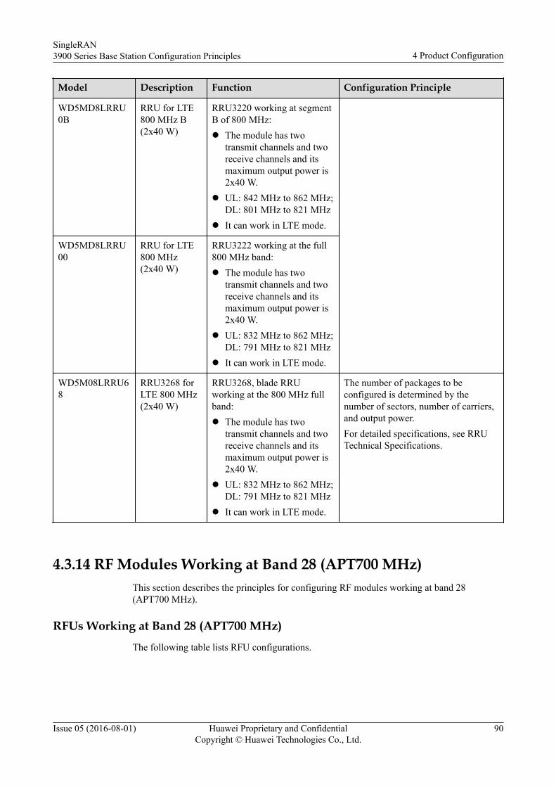
Model Description Function Configuration Principle
WD5MD8LRRU0B
RRU for LTE800 MHz B(2x40 W)
RRU3220 working at segmentB of 800 MHz:l The module has two
transmit channels and tworeceive channels and itsmaximum output power is2x40 W.
l UL: 842 MHz to 862 MHz;DL: 801 MHz to 821 MHz
l It can work in LTE mode.
WD5MD8LRRU00
RRU for LTE800 MHz(2x40 W)
RRU3222 working at the full800 MHz band:l The module has two
transmit channels and tworeceive channels and itsmaximum output power is2x40 W.
l UL: 832 MHz to 862 MHz;DL: 791 MHz to 821 MHz
l It can work in LTE mode.
WD5M08LRRU68
RRU3268 forLTE 800 MHz(2x40 W)
RRU3268, blade RRUworking at the 800 MHz fullband:l The module has two
transmit channels and tworeceive channels and itsmaximum output power is2x40 W.
l UL: 832 MHz to 862 MHz;DL: 791 MHz to 821 MHz
l It can work in LTE mode.
The number of packages to beconfigured is determined by thenumber of sectors, number of carriers,and output power.For detailed specifications, see RRUTechnical Specifications.
4.3.14 RF Modules Working at Band 28 (APT700 MHz)This section describes the principles for configuring RF modules working at band 28(APT700 MHz).
RFUs Working at Band 28 (APT700 MHz)The following table lists RFU configurations.
SingleRAN3900 Series Base Station Configuration Principles 4 Product Configuration
Issue 05 (2016-08-01) Huawei Proprietary and ConfidentialCopyright © Huawei Technologies Co., Ltd.
90
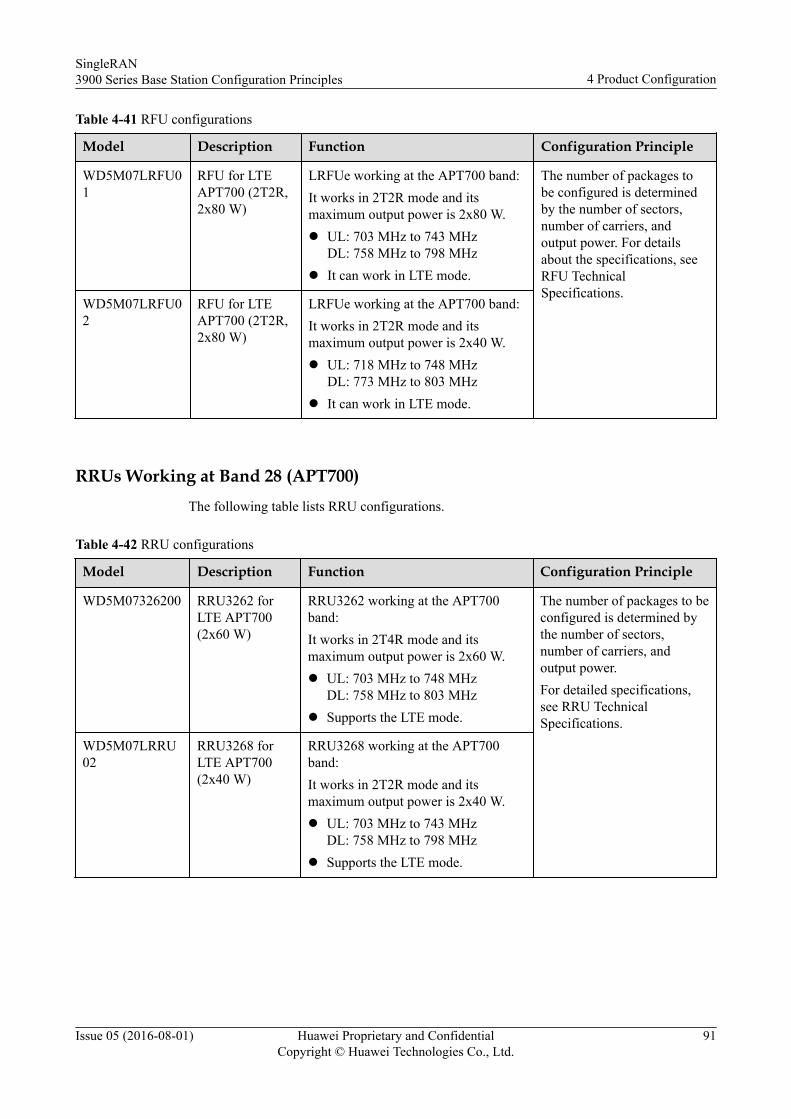
Table 4-41 RFU configurations
Model Description Function Configuration Principle
WD5M07LRFU01
RFU for LTEAPT700 (2T2R,2x80 W)
LRFUe working at the APT700 band:It works in 2T2R mode and itsmaximum output power is 2x80 W.l UL: 703 MHz to 743 MHz
DL: 758 MHz to 798 MHzl It can work in LTE mode.
The number of packages tobe configured is determinedby the number of sectors,number of carriers, andoutput power. For detailsabout the specifications, seeRFU TechnicalSpecifications.
WD5M07LRFU02
RFU for LTEAPT700 (2T2R,2x80 W)
LRFUe working at the APT700 band:It works in 2T2R mode and itsmaximum output power is 2x40 W.l UL: 718 MHz to 748 MHz
DL: 773 MHz to 803 MHzl It can work in LTE mode.
RRUs Working at Band 28 (APT700)The following table lists RRU configurations.
Table 4-42 RRU configurations
Model Description Function Configuration Principle
WD5M07326200 RRU3262 forLTE APT700(2x60 W)
RRU3262 working at the APT700band:It works in 2T4R mode and itsmaximum output power is 2x60 W.l UL: 703 MHz to 748 MHz
DL: 758 MHz to 803 MHzl Supports the LTE mode.
The number of packages to beconfigured is determined bythe number of sectors,number of carriers, andoutput power.For detailed specifications,see RRU TechnicalSpecifications.
WD5M07LRRU02
RRU3268 forLTE APT700(2x40 W)
RRU3268 working at the APT700band:It works in 2T2R mode and itsmaximum output power is 2x40 W.l UL: 703 MHz to 743 MHz
DL: 758 MHz to 798 MHzl Supports the LTE mode.
SingleRAN3900 Series Base Station Configuration Principles 4 Product Configuration
Issue 05 (2016-08-01) Huawei Proprietary and ConfidentialCopyright © Huawei Technologies Co., Ltd.
91
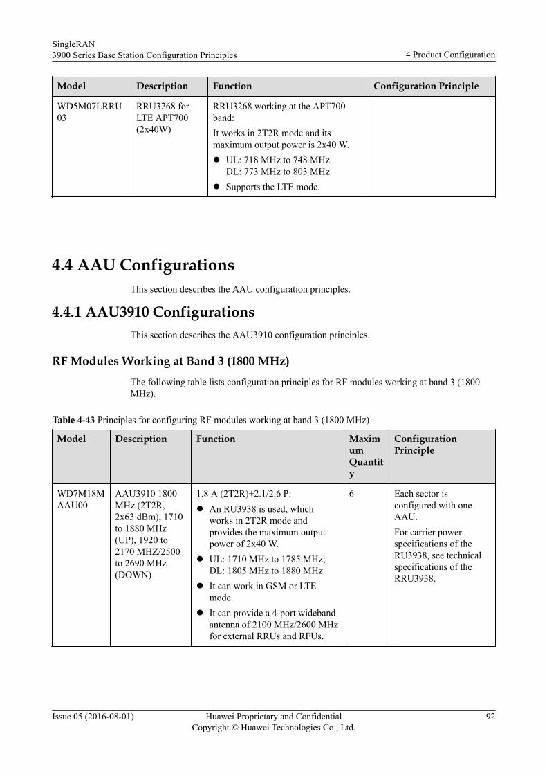
Model Description Function Configuration Principle
WD5M07LRRU03
RRU3268 forLTE APT700(2x40W)
RRU3268 working at the APT700band:It works in 2T2R mode and itsmaximum output power is 2x40 W.l UL: 718 MHz to 748 MHz
DL: 773 MHz to 803 MHzl Supports the LTE mode.
4.4 AAU ConfigurationsThis section describes the AAU configuration principles.
4.4.1 AAU3910 ConfigurationsThis section describes the AAU3910 configuration principles.
RF Modules Working at Band 3 (1800 MHz)The following table lists configuration principles for RF modules working at band 3 (1800MHz).
Table 4-43 Principles for configuring RF modules working at band 3 (1800 MHz)
Model Description Function MaximumQuantity
ConfigurationPrinciple
WD7M18MAAU00
AAU3910 1800MHz (2T2R,2x63 dBm), 1710to 1880 MHz(UP), 1920 to2170 MHZ/2500to 2690 MHz(DOWN)
1.8 A (2T2R)+2.1/2.6 P:l An RU3938 is used, which
works in 2T2R mode andprovides the maximum outputpower of 2x40 W.
l UL: 1710 MHz to 1785 MHz;DL: 1805 MHz to 1880 MHz
l It can work in GSM or LTEmode.
l It can provide a 4-port widebandantenna of 2100 MHz/2600 MHzfor external RRUs and RFUs.
6 Each sector isconfigured with oneAAU.For carrier powerspecifications of theRU3938, see technicalspecifications of theRRU3938.
SingleRAN3900 Series Base Station Configuration Principles 4 Product Configuration
Issue 05 (2016-08-01) Huawei Proprietary and ConfidentialCopyright © Huawei Technologies Co., Ltd.
92
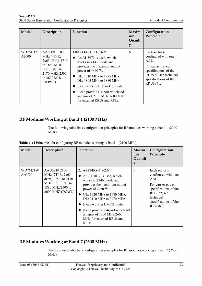
Model Description Function MaximumQuantity
ConfigurationPrinciple
WD7MJTAA2000
AAU3910 1800MHz (4T4R,2x63 dBm), 1710to 1880 MHz(UP), 1920 to2170 MHZ/2500to 2690 MHz(DOWN)
1.8A (4T4R)+2.1/2.6 P:l An RU3971 is used, which
works in 4T4R mode andprovides the maximum outputpower of 4x40 W.
l UL: 1710 MHz to 1785 MHz;DL: 1805 MHz to 1880 MHz
l It can work in LTE or GL mode.l It can provide a 4-port wideband
antenna of 2100 MHz/2600 MHzfor external RRUs and RFUs.
6 Each sector isconfigured with oneAAU.For carrier powerspecifications of theRU3971, see technicalspecifications of theRRU3971.
RF Modules Working at Band 1 (2100 MHz)
The following table lists configuration principles for RF modules working at band 1 (2100MHz).
Table 4-44 Principles for configuring RF modules working at band 1 (2100 MHz)
Model Description Function MaximumQuantity
ConfigurationPrinciple
WD7M21WAAU00
AAU3910 2100MHz (2T4R, 2x65dBm), 1920 to 2170MHz (UP), 1710 to1880 MHz/2500 to2690 MHZ (DOWN)
2.1A (2T4R)+1.8/2.6 P:l An RU3832 is used, which
works in 2T4R mode andprovides the maximum outputpower of 2x60 W.
l UL: 1920 MHz to 1980 MHz;DL: 2110 MHz to 2170 MHz
l It can work in UMTS mode.l It can provide a 4-port wideband
antenna of 1800 MHz/2600MHz for external RRUs andRFUs.
6 Each sector isconfigured with oneAAU.For carrier powerspecifications of theRU3832, seetechnicalspecifications of theRRU3832.
RF Modules Working at Band 7 (2600 MHz)
The following table lists configuration principles for RF modules working at band 7 (2600MHz).
SingleRAN3900 Series Base Station Configuration Principles 4 Product Configuration
Issue 05 (2016-08-01) Huawei Proprietary and ConfidentialCopyright © Huawei Technologies Co., Ltd.
93
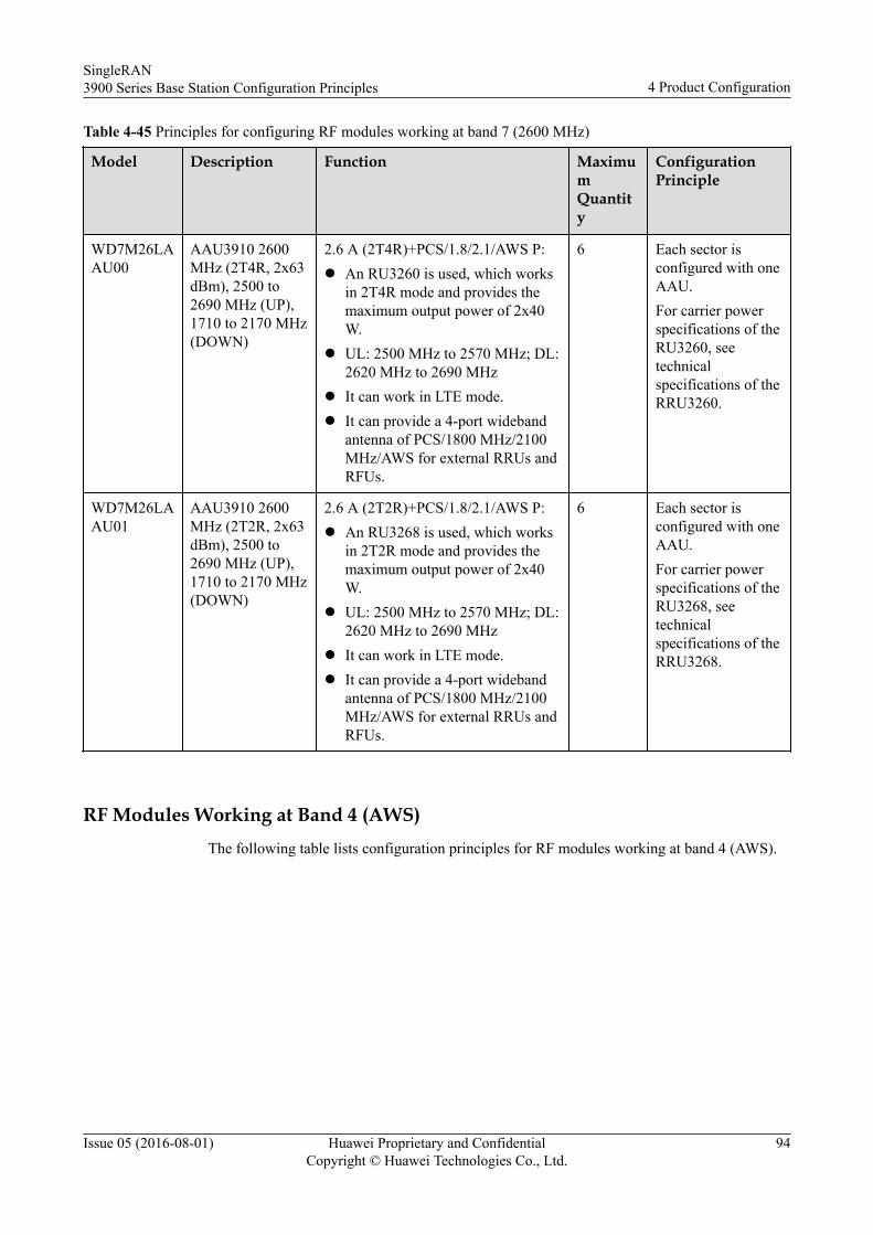
Table 4-45 Principles for configuring RF modules working at band 7 (2600 MHz)
Model Description Function MaximumQuantity
ConfigurationPrinciple
WD7M26LAAU00
AAU3910 2600MHz (2T4R, 2x63dBm), 2500 to2690 MHz (UP),1710 to 2170 MHz(DOWN)
2.6 A (2T4R)+PCS/1.8/2.1/AWS P:l An RU3260 is used, which works
in 2T4R mode and provides themaximum output power of 2x40W.
l UL: 2500 MHz to 2570 MHz; DL:2620 MHz to 2690 MHz
l It can work in LTE mode.l It can provide a 4-port wideband
antenna of PCS/1800 MHz/2100MHz/AWS for external RRUs andRFUs.
6 Each sector isconfigured with oneAAU.For carrier powerspecifications of theRU3260, seetechnicalspecifications of theRRU3260.
WD7M26LAAU01
AAU3910 2600MHz (2T2R, 2x63dBm), 2500 to2690 MHz (UP),1710 to 2170 MHz(DOWN)
2.6 A (2T2R)+PCS/1.8/2.1/AWS P:l An RU3268 is used, which works
in 2T2R mode and provides themaximum output power of 2x40W.
l UL: 2500 MHz to 2570 MHz; DL:2620 MHz to 2690 MHz
l It can work in LTE mode.l It can provide a 4-port wideband
antenna of PCS/1800 MHz/2100MHz/AWS for external RRUs andRFUs.
6 Each sector isconfigured with oneAAU.For carrier powerspecifications of theRU3268, seetechnicalspecifications of theRRU3268.
RF Modules Working at Band 4 (AWS)The following table lists configuration principles for RF modules working at band 4 (AWS).
SingleRAN3900 Series Base Station Configuration Principles 4 Product Configuration
Issue 05 (2016-08-01) Huawei Proprietary and ConfidentialCopyright © Huawei Technologies Co., Ltd.
94
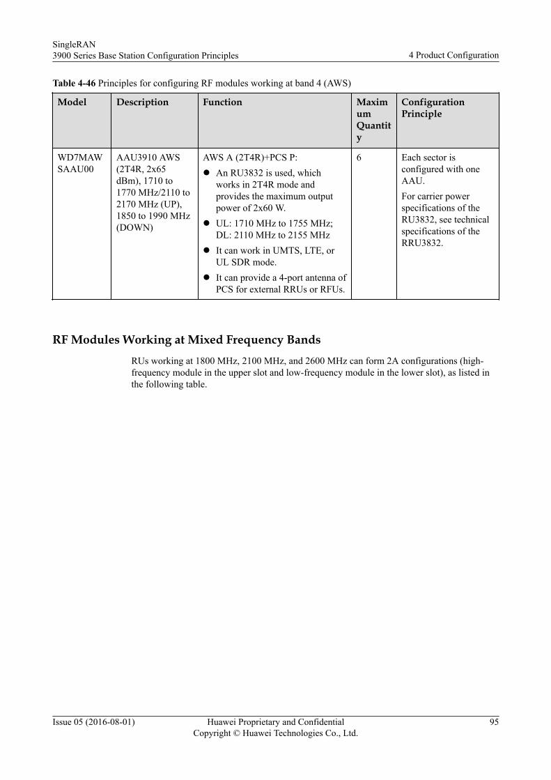
Table 4-46 Principles for configuring RF modules working at band 4 (AWS)
Model Description Function MaximumQuantity
ConfigurationPrinciple
WD7MAWSAAU00
AAU3910 AWS(2T4R, 2x65dBm), 1710 to1770 MHz/2110 to2170 MHz (UP),1850 to 1990 MHz(DOWN)
AWS A (2T4R)+PCS P:l An RU3832 is used, which
works in 2T4R mode andprovides the maximum outputpower of 2x60 W.
l UL: 1710 MHz to 1755 MHz;DL: 2110 MHz to 2155 MHz
l It can work in UMTS, LTE, orUL SDR mode.
l It can provide a 4-port antenna ofPCS for external RRUs or RFUs.
6 Each sector isconfigured with oneAAU.For carrier powerspecifications of theRU3832, see technicalspecifications of theRRU3832.
RF Modules Working at Mixed Frequency BandsRUs working at 1800 MHz, 2100 MHz, and 2600 MHz can form 2A configurations (high-frequency module in the upper slot and low-frequency module in the lower slot), as listed inthe following table.
SingleRAN3900 Series Base Station Configuration Principles 4 Product Configuration
Issue 05 (2016-08-01) Huawei Proprietary and ConfidentialCopyright © Huawei Technologies Co., Ltd.
95
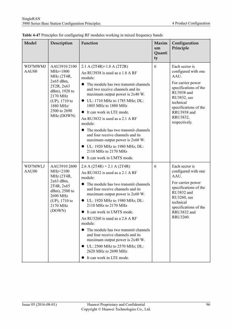
Table 4-47 Principles for configuring RF modules working in mixed frequency bands
Model Description Function MaximumQuantity
ConfigurationPrinciple
WD7MWMJAAU00
AAU3910 2100MHz+1800MHz (2T4R,2x65 dBm,2T2R, 2x63dBm), 1920 to2170 MHz(UP), 1710 to1880 MHz/2500 to 2690MHz (DOWN)
2.1 A (2T4R)+1.8 A (2T2R)An RU3938 is used as a 1.8 A RFmodule:l The module has two transmit channels
and two receive channels and itsmaximum output power is 2x40 W.
l UL: 1710 MHz to 1785 MHz; DL:1805 MHz to 1880 MHz
l It can work in LTE mode.An RU3832 is used as a 2.1 A RFmodule:l The module has two transmit channels
and four receive channels and itsmaximum output power is 2x60 W.
l UL: 1920 MHz to 1980 MHz; DL:2110 MHz to 2170 MHz
l It can work in UMTS mode.
6 Each sector isconfigured with oneAAU.For carrier powerspecifications of theRU3938 andRU3832, seetechnicalspecifications of theRRU3938 andRRU3832,respectively.
WD7MWLJAAU00
AAU3910 2600MHz+2100MHz (2T4R,2x63 dBm,2T4R, 2x65dBm), 2500 to2690 MHz(UP), 1710 to2170 MHz(DOWN)
2.6 A (2T4R) + 2.1 A (2T4R)An RU3832 is used as a 2.1 A RFmodule:l The module has two transmit channels
and four receive channels and itsmaximum output power is 2x60 W.
l UL: 1920 MHz to 1980 MHz; DL:2110 MHz to 2170 MHz
l It can work in UMTS mode.An RU3260 is used as a 2.6 A RFmodule:l The module has two transmit channels
and four receive channels and itsmaximum output power is 2x40 W.
l UL: 2500 MHz to 2570 MHz; DL:2620 MHz to 2690 MHz
l It can work in LTE mode.
6 Each sector isconfigured with oneAAU.For carrier powerspecifications of theRU3832 andRU3260, seetechnicalspecifications of theRRU3832 andRRU3260.
SingleRAN3900 Series Base Station Configuration Principles 4 Product Configuration
Issue 05 (2016-08-01) Huawei Proprietary and ConfidentialCopyright © Huawei Technologies Co., Ltd.
96
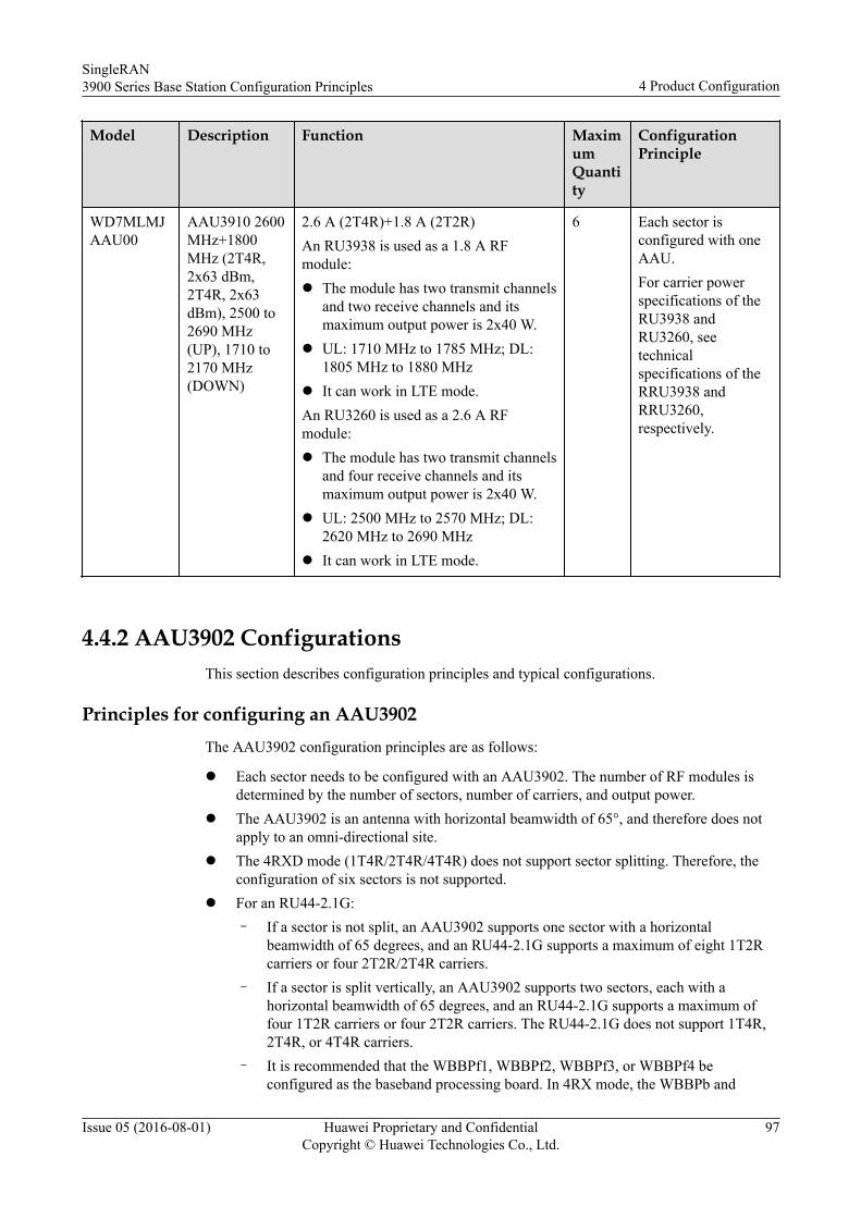
Model Description Function MaximumQuantity
ConfigurationPrinciple
WD7MLMJAAU00
AAU3910 2600MHz+1800MHz (2T4R,2x63 dBm,2T4R, 2x63dBm), 2500 to2690 MHz(UP), 1710 to2170 MHz(DOWN)
2.6 A (2T4R)+1.8 A (2T2R)An RU3938 is used as a 1.8 A RFmodule:l The module has two transmit channels
and two receive channels and itsmaximum output power is 2x40 W.
l UL: 1710 MHz to 1785 MHz; DL:1805 MHz to 1880 MHz
l It can work in LTE mode.An RU3260 is used as a 2.6 A RFmodule:l The module has two transmit channels
and four receive channels and itsmaximum output power is 2x40 W.
l UL: 2500 MHz to 2570 MHz; DL:2620 MHz to 2690 MHz
l It can work in LTE mode.
6 Each sector isconfigured with oneAAU.For carrier powerspecifications of theRU3938 andRU3260, seetechnicalspecifications of theRRU3938 andRRU3260,respectively.
4.4.2 AAU3902 ConfigurationsThis section describes configuration principles and typical configurations.
Principles for configuring an AAU3902The AAU3902 configuration principles are as follows:
l Each sector needs to be configured with an AAU3902. The number of RF modules isdetermined by the number of sectors, number of carriers, and output power.
l The AAU3902 is an antenna with horizontal beamwidth of 65°, and therefore does notapply to an omni-directional site.
l The 4RXD mode (1T4R/2T4R/4T4R) does not support sector splitting. Therefore, theconfiguration of six sectors is not supported.
l For an RU44-2.1G:– If a sector is not split, an AAU3902 supports one sector with a horizontal
beamwidth of 65 degrees, and an RU44-2.1G supports a maximum of eight 1T2Rcarriers or four 2T2R/2T4R carriers.
– If a sector is split vertically, an AAU3902 supports two sectors, each with ahorizontal beamwidth of 65 degrees, and an RU44-2.1G supports a maximum offour 1T2R carriers or four 2T2R carriers. The RU44-2.1G does not support 1T4R,2T4R, or 4T4R carriers.
– It is recommended that the WBBPf1, WBBPf2, WBBPf3, or WBBPf4 beconfigured as the baseband processing board. In 4RX mode, the WBBPb and
SingleRAN3900 Series Base Station Configuration Principles 4 Product Configuration
Issue 05 (2016-08-01) Huawei Proprietary and ConfidentialCopyright © Huawei Technologies Co., Ltd.
97
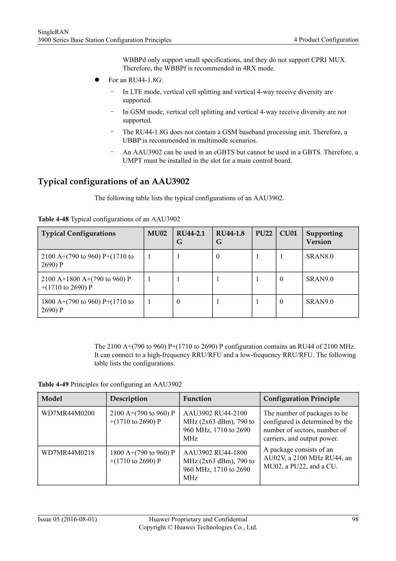
WBBPd only support small specifications, and they do not support CPRI MUX.Therefore, the WBBPf is recommended in 4RX mode.
l For an RU44-1.8G:
– In LTE mode, vertical cell splitting and vertical 4-way receive diversity aresupported.
– In GSM mode, vertical cell splitting and vertical 4-way receive diversity are notsupported.
– The RU44-1.8G does not contain a GSM baseband processing unit. Therefore, aUBBP is recommended in multimode scenarios.
– An AAU3902 can be used in an eGBTS but cannot be used in a GBTS. Therefore, aUMPT must be installed in the slot for a main control board.
Typical configurations of an AAU3902
The following table lists the typical configurations of an AAU3902.
Table 4-48 Typical configurations of an AAU3902
Typical Configurations MU02 RU44-2.1G
RU44-1.8G
PU22 CU01 SupportingVersion
2100 A+(790 to 960) P+(1710 to2690) P
1 1 0 1 1 SRAN8.0
2100 A+1800 A+(790 to 960) P+(1710 to 2690) P
1 1 1 1 0 SRAN9.0
1800 A+(790 to 960) P+(1710 to2690) P
1 0 1 1 0 SRAN9.0
The 2100 A+(790 to 960) P+(1710 to 2690) P configuration contains an RU44 of 2100 MHz.It can connect to a high-frequency RRU/RFU and a low-frequency RRU/RFU. The followingtable lists the configurations.
Table 4-49 Principles for configuring an AAU3902
Model Description Function Configuration Principle
WD7MR44M0200 2100 A+(790 to 960) P+(1710 to 2690) P
AAU3902 RU44-2100MHz (2x63 dBm), 790 to960 MHz, 1710 to 2690MHz
The number of packages to beconfigured is determined by thenumber of sectors, number ofcarriers, and output power.A package consists of anAU02V, a 2100 MHz RU44, anMU02, a PU22, and a CU.
WD7MR44M0218 1800 A+(790 to 960) P+(1710 to 2690) P
AAU3902 RU44-1800MHz (2x63 dBm), 790 to960 MHz, 1710 to 2690MHz
SingleRAN3900 Series Base Station Configuration Principles 4 Product Configuration
Issue 05 (2016-08-01) Huawei Proprietary and ConfidentialCopyright © Huawei Technologies Co., Ltd.
98
4.4.3 AAU3940 ConfigurationsThis section describes configuration principles and typical configurations of the AAU3940.
Principles for Configuring an AAU3940
The AAU3940 configuration principles are as follows:
l Each sector needs to be configured with an AAU3940. The number of RF modules isdetermined by the number of sectors, number of carriers, and output power.
l The AAU3940 has an antenna with horizontal beamwidth of 70°, and therefore does notapply to an omni-directional site.
l The AAU3940 only applies to sectorized cells. Each sector requires at most oneAAU3940.
l The AAU3940 does not support mechanical tilt but only supports electrical tilt. Thehorizontal angle of the AAU3940 is adjusted using mounting kits.
l The AAU3940 supports one AC or DC power input. The AAU3940 also supports 10 kAdifferential mode and 20 kA common mode with surge protection capabilities.
l The AAU3940 can be used together with the BBU3900, BBU3910, or BBU3910A.
Configuration principles of CPRI portsl The AAU3940 provides two CPRI ports, which support a rate of 1.25 Gbit/s, 2.5 Gbit/s,
4.9 Gbit/s, or 9.8 Gbit/s.l The AAU3940 supports dual-band and UL dual-mode. The dual-star, star, and chain
topologies are used for CPRI connection.l In remote networking scenarios, the star topology for CPRI connections is recommended
for a base station located on a rooftop. A cascading topology is recommended for a basestation located along the streets to reduce fiber optic cables.
l Optical modules supporting a CPRI rate of 9.8 Gbit/s are recommended.
Typical Configurations of an AAU3940
The following table lists the carrier configuration of the AAU3940.
Table 4-50 Carrier specifications of AAU3940
Description Function WorkingMode
Configuration Capacity
1.8 GHz (LTE)+2.1 GHz (LTE+UMTS)
1.8 GHz (UL: 1710 MHz to1785 MHz, DL: 1805 MHz to1880 MHz) + 2.1 GHz (UL:1920 MHz to 1980 MHz, DL:2110 MHz to 2170 MHz)
UMTS only Six 1T2R carriers or four 2T2Rcarriers
LTE only 2x20 MHz 2T2R
UL Four UMTS 1T2R carriers and twoLTE 20 MHz 2T2R carriersTwo UMTS 2T2R carriers and twoLTE 20 MHz 2T2R carriers
AWS (LTE)+PCS(LTE+UMTS)
AWS (UL: 1710 MHz to 1755MHz, DL: 2110 MHz to 2155
UMTS only 6C 1T2R or 4C 2T2R
SingleRAN3900 Series Base Station Configuration Principles 4 Product Configuration
Issue 05 (2016-08-01) Huawei Proprietary and ConfidentialCopyright © Huawei Technologies Co., Ltd.
99
Description Function WorkingMode
Configuration Capacity
MHz)+PCS (UL: 1850 MHz to1910 MHz, DL: 1930 MHz to1990 MHz)
LTE only 2x20 MHz 2T2R
UL Four UMTS 1T2R carriers and twoLTE 20 MHz 2T2R carriersTwo UMTS 2T2R carriers and twoLTE 20 MHz 2T2R carriers
The following table lists the AAU3940 configurations.
Table 4-51 AAU3940 configurations
Model Description Function MaximumQuantity
ConfigurationPrinciple
WD7MAAU39400
Function Module,AAU3940, FDDMulti-carriersBand Transceiver(TX: 1805-1880MHz, RX:1710-1785MHz/TX:2110-2170 MHz,RX: 1920-1980MHz, 10 G, 220V AC, 14/14.5dBi, -3-12 degRET)
1800 MHz+2100 MHz (2T2R):l The wideband module (2T2R) is
used and its maximum outputpower is 2x40 W.
l TX: 1805 MHz to 1880 MHz,RX: 1710 MHz to 1785MHz/TX: 2110 MHz to 2170MHz, RX: 1920 MHz to 1980MHz
l It can work in UMTS, LTE, orUL mode.
l Power supply: 220 V AC
6 Each sector isconfigured with oneAAU.For carrier powerspecifications of theAAU3940, see technicalspecifications of theAAU3940.
WD7MIRTB7M0C
Function Module-AAU3940-FDDMulti-carriersBand Transceiver(TX: 1825-1875MHz, RX:1730-1780MHz/TX:2110-2170 MHz,RX: 1920-1980MHz, 10 Gbit/s,DC, 2T2R)
1800 MHz+2100 MHz (2T2R):l The wideband module (2T2R) is
used and its maximum outputpower is 2x40 W.
l TX: 1805 MHz to 1880 MHz,RX: 1710 MHz to 1785MHz/TX: 2110 MHz to 2170MHz, RX: 1920 MHz to 1980MHz
l It can work in UMTS, LTE, orUL mode.
l Power supply: -48 V DC
6 Each sector isconfigured with oneAAU.For carrier powerspecifications of theAAU3940, see technicalspecifications of theAAU3940.
SingleRAN3900 Series Base Station Configuration Principles 4 Product Configuration
Issue 05 (2016-08-01) Huawei Proprietary and ConfidentialCopyright © Huawei Technologies Co., Ltd.
100
Model Description Function MaximumQuantity
ConfigurationPrinciple
WD7MAWS39400
Function Module,AAU3940, FDDMulti-carriersBand Transceiver(TX: 2110MHz-2155 MHz,RX: 1710MHz-1755MHz/TX: 1930MHz-1990 MHz,RX: 1850MHz-1910 MHz,10 G, DC,14/14.5 dBi,-3-12 deg RET)
AWS+PCS (2T2R):l The wideband module (2T2R) is
used and its maximum outputpower is 2x40 W.
l AWS (UL: 1710 MHz to 1755MHz, DL: 2110 MHz to 2155MHz)+PCS (UL: 1850 MHz to1910 MHz, DL: 1930 MHz to1990 MHz)
l It can work in UMTS, LTE, orUL mode.
l Power supply: -48 V DC
6 Each sector isconfigured with oneAAU.For carrier powerspecifications of theAAU3940, see technicalspecifications of theAAU3940.
4.4.4 AAU3920 ConfigurationsThis section describes configuration principles and typical configurations of the AAU3920.
Principles for Configuring an AAU3920
The AAU3920 configuration principles are as follows:
l The baseband processing boards can be configured for UMTS are WBBPb1 to WBBPb4,WBBPd1 to WBBPd3, and WBBPf1 to WBBPf4. In 4RX mode, the WBBPb andWBBPd only support small specifications, and they do not support CPRI MUX.Therefore, the WBBPf is recommended in 4RX mode.
l A UBBPd can be configured as a baseband processing board in LTE mode to support ULmode in the future.
l The AAU3920 supports a -48 V DC power supply socket and does not support powercascading.
l The passive antennas of the AAU3920 can be used on devices provided by Huawei or athird party.
The AAU3920 CPRI configuration principles are as follows:l The active RU configured on the AAU3920 provides two CPRI ports to connect to
BBUs. Each CPRI port supports a rate of 9.8 Gbit/s. For LO/UL base stations inwideband 2x2T4R mode, the 2:1 Compression and CPRI MUX features need to besupported.
l Multiple AAU3920s cannot be cascaded because of bandwidth limitation. In smallbandwidth configuration scenarios, a maximum of four cascading levels must besupported. During the cascading, you need to consider the number of cells supported byCPRI bandwidth and CPRI port adaptive capabilities.
SingleRAN3900 Series Base Station Configuration Principles 4 Product Configuration
Issue 05 (2016-08-01) Huawei Proprietary and ConfidentialCopyright © Huawei Technologies Co., Ltd.
101
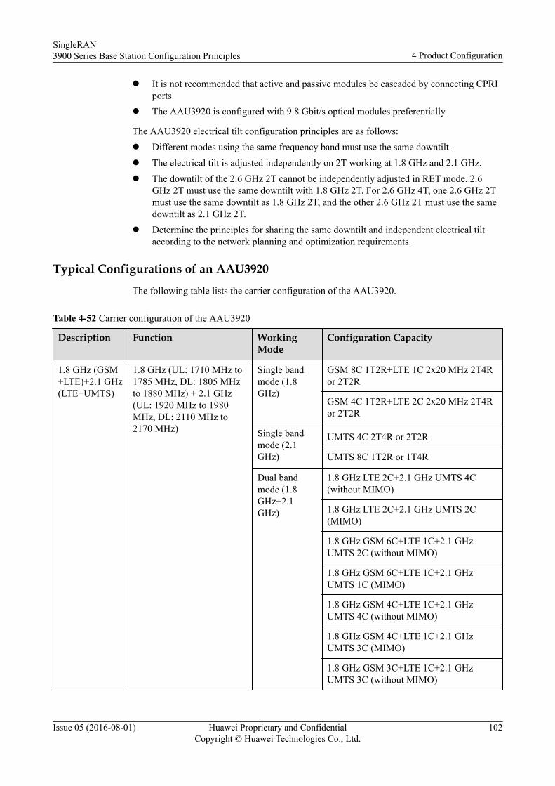
l It is not recommended that active and passive modules be cascaded by connecting CPRIports.
l The AAU3920 is configured with 9.8 Gbit/s optical modules preferentially.
The AAU3920 electrical tilt configuration principles are as follows:l Different modes using the same frequency band must use the same downtilt.l The electrical tilt is adjusted independently on 2T working at 1.8 GHz and 2.1 GHz.l The downtilt of the 2.6 GHz 2T cannot be independently adjusted in RET mode. 2.6
GHz 2T must use the same downtilt with 1.8 GHz 2T. For 2.6 GHz 4T, one 2.6 GHz 2Tmust use the same downtilt as 1.8 GHz 2T, and the other 2.6 GHz 2T must use the samedowntilt as 2.1 GHz 2T.
l Determine the principles for sharing the same downtilt and independent electrical tiltaccording to the network planning and optimization requirements.
Typical Configurations of an AAU3920
The following table lists the carrier configuration of the AAU3920.
Table 4-52 Carrier configuration of the AAU3920
Description Function WorkingMode
Configuration Capacity
1.8 GHz (GSM+LTE)+2.1 GHz(LTE+UMTS)
1.8 GHz (UL: 1710 MHz to1785 MHz, DL: 1805 MHzto 1880 MHz) + 2.1 GHz(UL: 1920 MHz to 1980MHz, DL: 2110 MHz to2170 MHz)
Single bandmode (1.8GHz)
GSM 8C 1T2R+LTE 1C 2x20 MHz 2T4Ror 2T2R
GSM 4C 1T2R+LTE 2C 2x20 MHz 2T4Ror 2T2R
Single bandmode (2.1GHz)
UMTS 4C 2T4R or 2T2R
UMTS 8C 1T2R or 1T4R
Dual bandmode (1.8GHz+2.1GHz)
1.8 GHz LTE 2C+2.1 GHz UMTS 4C(without MIMO)
1.8 GHz LTE 2C+2.1 GHz UMTS 2C(MIMO)
1.8 GHz GSM 6C+LTE 1C+2.1 GHzUMTS 2C (without MIMO)
1.8 GHz GSM 6C+LTE 1C+2.1 GHzUMTS 1C (MIMO)
1.8 GHz GSM 4C+LTE 1C+2.1 GHzUMTS 4C (without MIMO)
1.8 GHz GSM 4C+LTE 1C+2.1 GHzUMTS 3C (MIMO)
1.8 GHz GSM 3C+LTE 1C+2.1 GHzUMTS 3C (without MIMO)
SingleRAN3900 Series Base Station Configuration Principles 4 Product Configuration
Issue 05 (2016-08-01) Huawei Proprietary and ConfidentialCopyright © Huawei Technologies Co., Ltd.
102
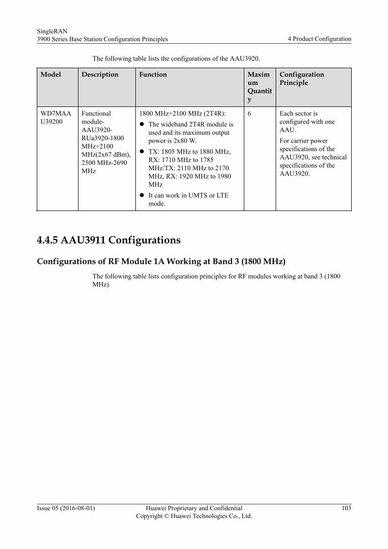
The following table lists the configurations of the AAU3920.
Model Description Function MaximumQuantity
ConfigurationPrinciple
WD7MAAU39200
Functionalmodule-AAU3920-RUa3920-1800MHz+2100MHz(2x67 dBm),2500 MHz-2690MHz
1800 MHz+2100 MHz (2T4R):l The wideband 2T4R module is
used and its maximum outputpower is 2x80 W.
l TX: 1805 MHz to 1880 MHz,RX: 1710 MHz to 1785MHz/TX: 2110 MHz to 2170MHz, RX: 1920 MHz to 1980MHz
l It can work in UMTS or LTEmode.
6 Each sector isconfigured with oneAAU.For carrier powerspecifications of theAAU3920, see technicalspecifications of theAAU3920.
4.4.5 AAU3911 Configurations
Configurations of RF Module 1A Working at Band 3 (1800 MHz)The following table lists configuration principles for RF modules working at band 3 (1800MHz).
SingleRAN3900 Series Base Station Configuration Principles 4 Product Configuration
Issue 05 (2016-08-01) Huawei Proprietary and ConfidentialCopyright © Huawei Technologies Co., Ltd.
103
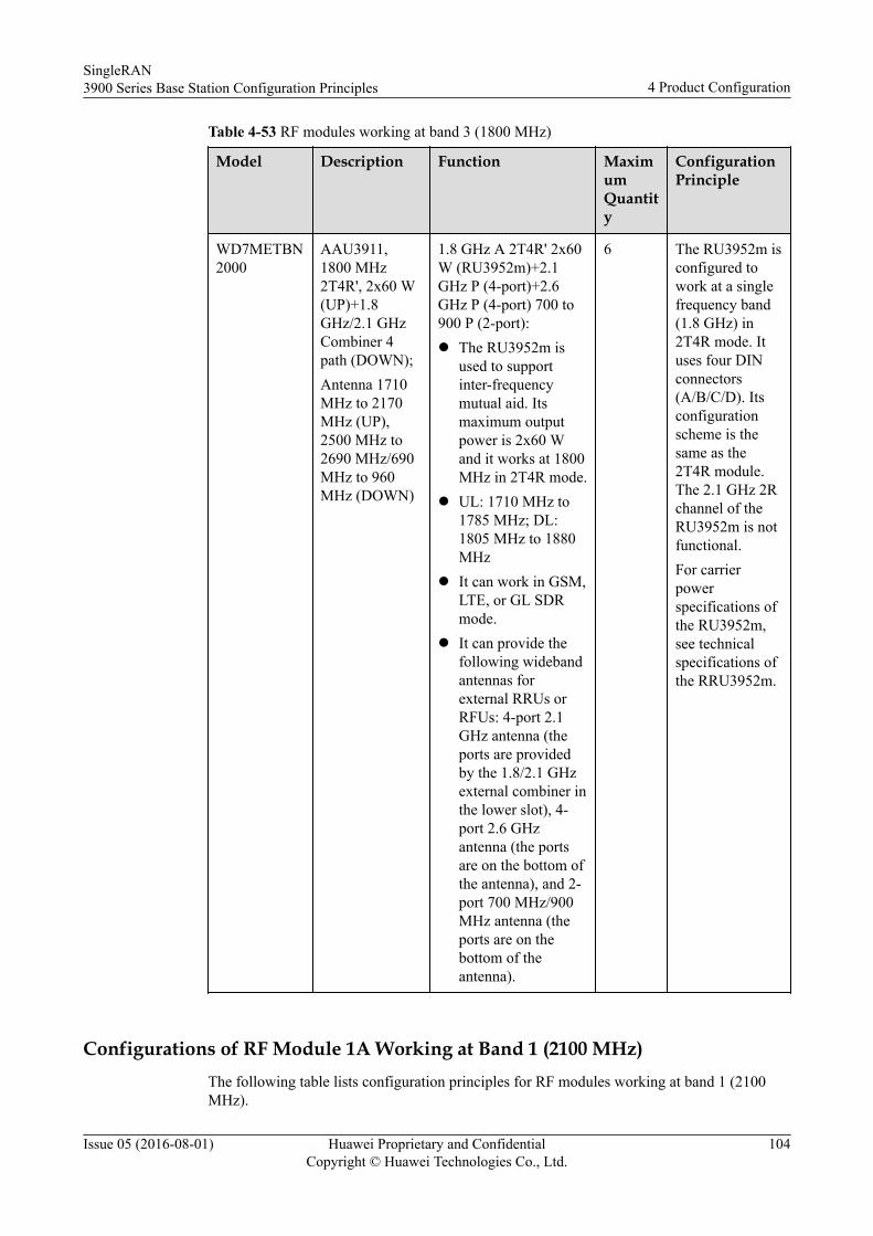
Table 4-53 RF modules working at band 3 (1800 MHz)
Model Description Function MaximumQuantity
ConfigurationPrinciple
WD7METBN2000
AAU3911,1800 MHz2T4R', 2x60 W(UP)+1.8GHz/2.1 GHzCombiner 4path (DOWN);Antenna 1710MHz to 2170MHz (UP),2500 MHz to2690 MHz/690MHz to 960MHz (DOWN)
1.8 GHz A 2T4R' 2x60W (RU3952m)+2.1GHz P (4-port)+2.6GHz P (4-port) 700 to900 P (2-port):l The RU3952m is
used to supportinter-frequencymutual aid. Itsmaximum outputpower is 2x60 Wand it works at 1800MHz in 2T4R mode.
l UL: 1710 MHz to1785 MHz; DL:1805 MHz to 1880MHz
l It can work in GSM,LTE, or GL SDRmode.
l It can provide thefollowing widebandantennas forexternal RRUs orRFUs: 4-port 2.1GHz antenna (theports are providedby the 1.8/2.1 GHzexternal combiner inthe lower slot), 4-port 2.6 GHzantenna (the portsare on the bottom ofthe antenna), and 2-port 700 MHz/900MHz antenna (theports are on thebottom of theantenna).
6 The RU3952m isconfigured towork at a singlefrequency band(1.8 GHz) in2T4R mode. Ituses four DINconnectors(A/B/C/D). Itsconfigurationscheme is thesame as the2T4R module.The 2.1 GHz 2Rchannel of theRU3952m is notfunctional.For carrierpowerspecifications ofthe RU3952m,see technicalspecifications ofthe RRU3952m.
Configurations of RF Module 1A Working at Band 1 (2100 MHz)The following table lists configuration principles for RF modules working at band 1 (2100MHz).
SingleRAN3900 Series Base Station Configuration Principles 4 Product Configuration
Issue 05 (2016-08-01) Huawei Proprietary and ConfidentialCopyright © Huawei Technologies Co., Ltd.
104
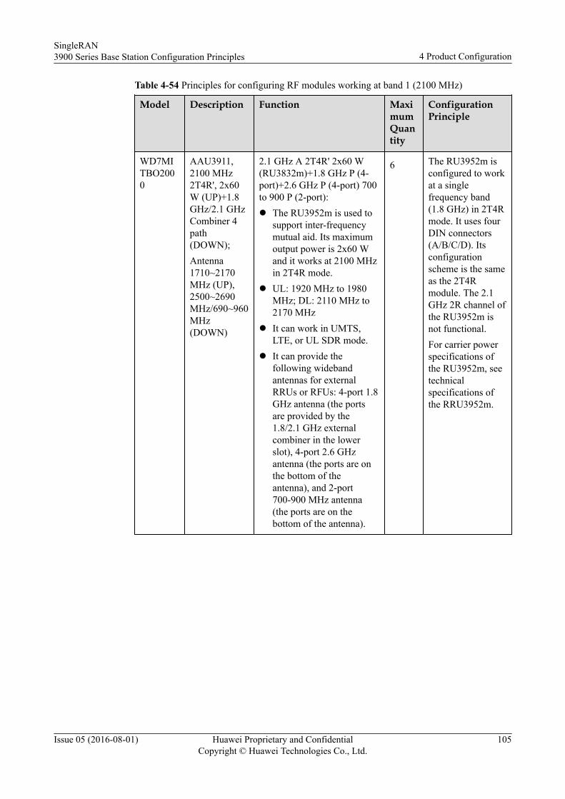
Table 4-54 Principles for configuring RF modules working at band 1 (2100 MHz)
Model Description Function MaximumQuantity
ConfigurationPrinciple
WD7MITBO2000
AAU3911,2100 MHz2T4R', 2x60W (UP)+1.8GHz/2.1 GHzCombiner 4path(DOWN);Antenna1710~2170MHz (UP),2500~2690MHz/690~960MHz(DOWN)
2.1 GHz A 2T4R' 2x60 W(RU3832m)+1.8 GHz P (4-port)+2.6 GHz P (4-port) 700to 900 P (2-port):l The RU3952m is used to
support inter-frequencymutual aid. Its maximumoutput power is 2x60 Wand it works at 2100 MHzin 2T4R mode.
l UL: 1920 MHz to 1980MHz; DL: 2110 MHz to2170 MHz
l It can work in UMTS,LTE, or UL SDR mode.
l It can provide thefollowing widebandantennas for externalRRUs or RFUs: 4-port 1.8GHz antenna (the portsare provided by the1.8/2.1 GHz externalcombiner in the lowerslot), 4-port 2.6 GHzantenna (the ports are onthe bottom of theantenna), and 2-port700-900 MHz antenna(the ports are on thebottom of the antenna).
6 The RU3952m isconfigured to workat a singlefrequency band(1.8 GHz) in 2T4Rmode. It uses fourDIN connectors(A/B/C/D). Itsconfigurationscheme is the sameas the 2T4Rmodule. The 2.1GHz 2R channel ofthe RU3952m isnot functional.For carrier powerspecifications ofthe RU3952m, seetechnicalspecifications ofthe RRU3952m.
SingleRAN3900 Series Base Station Configuration Principles 4 Product Configuration
Issue 05 (2016-08-01) Huawei Proprietary and ConfidentialCopyright © Huawei Technologies Co., Ltd.
105
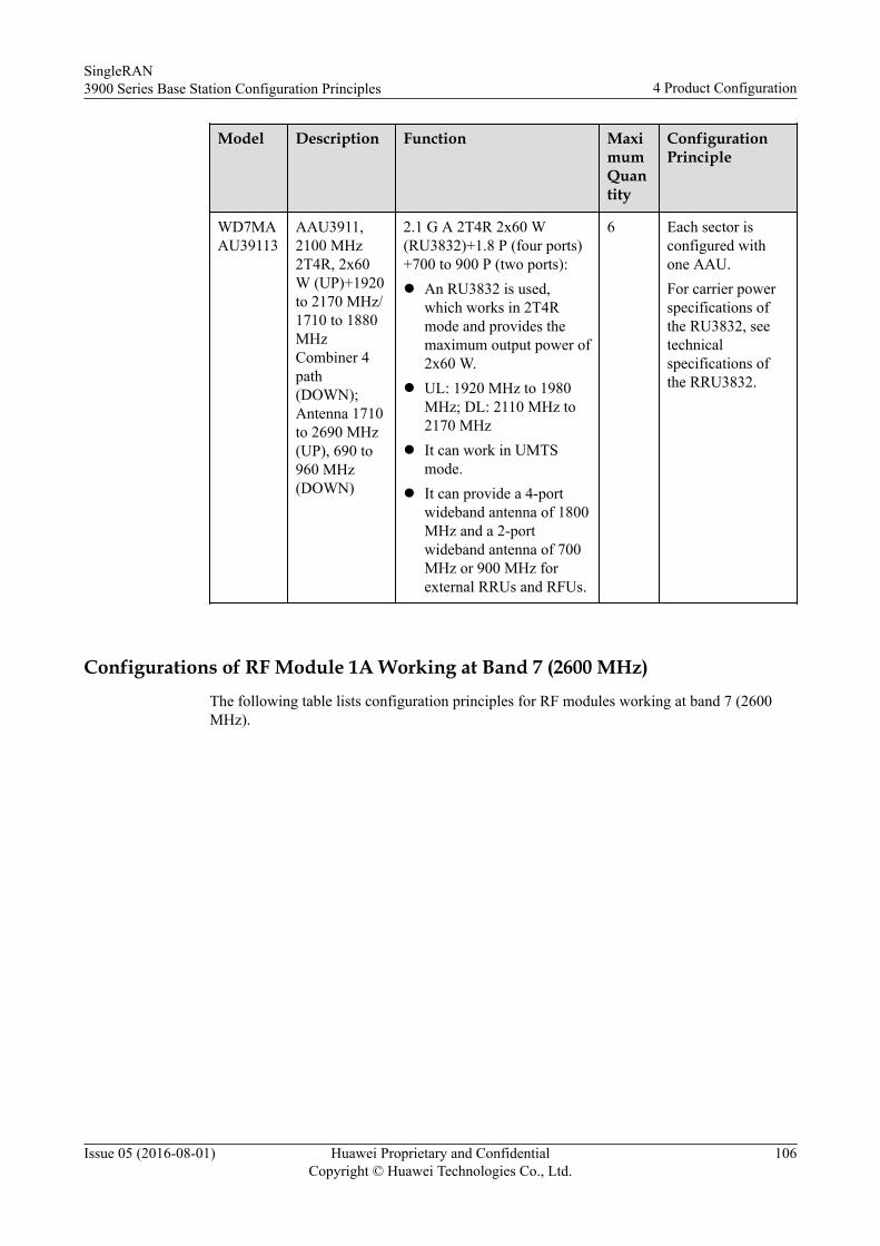
Model Description Function MaximumQuantity
ConfigurationPrinciple
WD7MAAU39113
AAU3911,2100 MHz2T4R, 2x60W (UP)+1920to 2170 MHz/1710 to 1880MHzCombiner 4path(DOWN);Antenna 1710to 2690 MHz(UP), 690 to960 MHz(DOWN)
2.1 G A 2T4R 2x60 W(RU3832)+1.8 P (four ports)+700 to 900 P (two ports):l An RU3832 is used,
which works in 2T4Rmode and provides themaximum output power of2x60 W.
l UL: 1920 MHz to 1980MHz; DL: 2110 MHz to2170 MHz
l It can work in UMTSmode.
l It can provide a 4-portwideband antenna of 1800MHz and a 2-portwideband antenna of 700MHz or 900 MHz forexternal RRUs and RFUs.
6 Each sector isconfigured withone AAU.For carrier powerspecifications ofthe RU3832, seetechnicalspecifications ofthe RRU3832.
Configurations of RF Module 1A Working at Band 7 (2600 MHz)The following table lists configuration principles for RF modules working at band 7 (2600MHz).
SingleRAN3900 Series Base Station Configuration Principles 4 Product Configuration
Issue 05 (2016-08-01) Huawei Proprietary and ConfidentialCopyright © Huawei Technologies Co., Ltd.
106
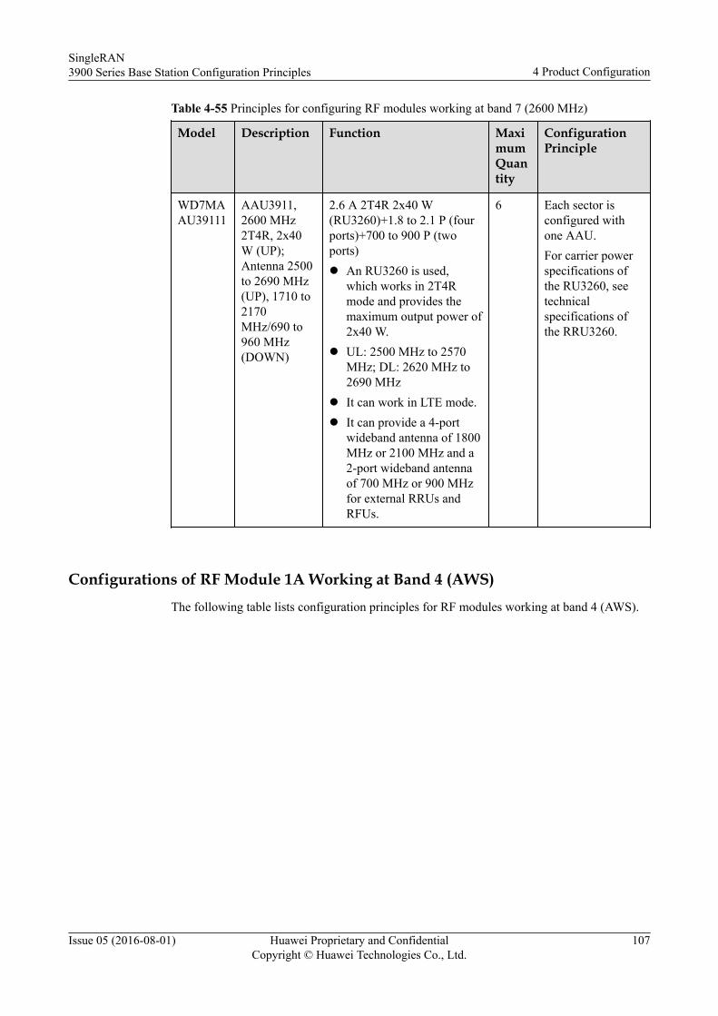
Table 4-55 Principles for configuring RF modules working at band 7 (2600 MHz)
Model Description Function MaximumQuantity
ConfigurationPrinciple
WD7MAAU39111
AAU3911,2600 MHz2T4R, 2x40W (UP);Antenna 2500to 2690 MHz(UP), 1710 to2170MHz/690 to960 MHz(DOWN)
2.6 A 2T4R 2x40 W(RU3260)+1.8 to 2.1 P (fourports)+700 to 900 P (twoports)l An RU3260 is used,
which works in 2T4Rmode and provides themaximum output power of2x40 W.
l UL: 2500 MHz to 2570MHz; DL: 2620 MHz to2690 MHz
l It can work in LTE mode.l It can provide a 4-port
wideband antenna of 1800MHz or 2100 MHz and a2-port wideband antennaof 700 MHz or 900 MHzfor external RRUs andRFUs.
6 Each sector isconfigured withone AAU.For carrier powerspecifications ofthe RU3260, seetechnicalspecifications ofthe RRU3260.
Configurations of RF Module 1A Working at Band 4 (AWS)The following table lists configuration principles for RF modules working at band 4 (AWS).
SingleRAN3900 Series Base Station Configuration Principles 4 Product Configuration
Issue 05 (2016-08-01) Huawei Proprietary and ConfidentialCopyright © Huawei Technologies Co., Ltd.
107
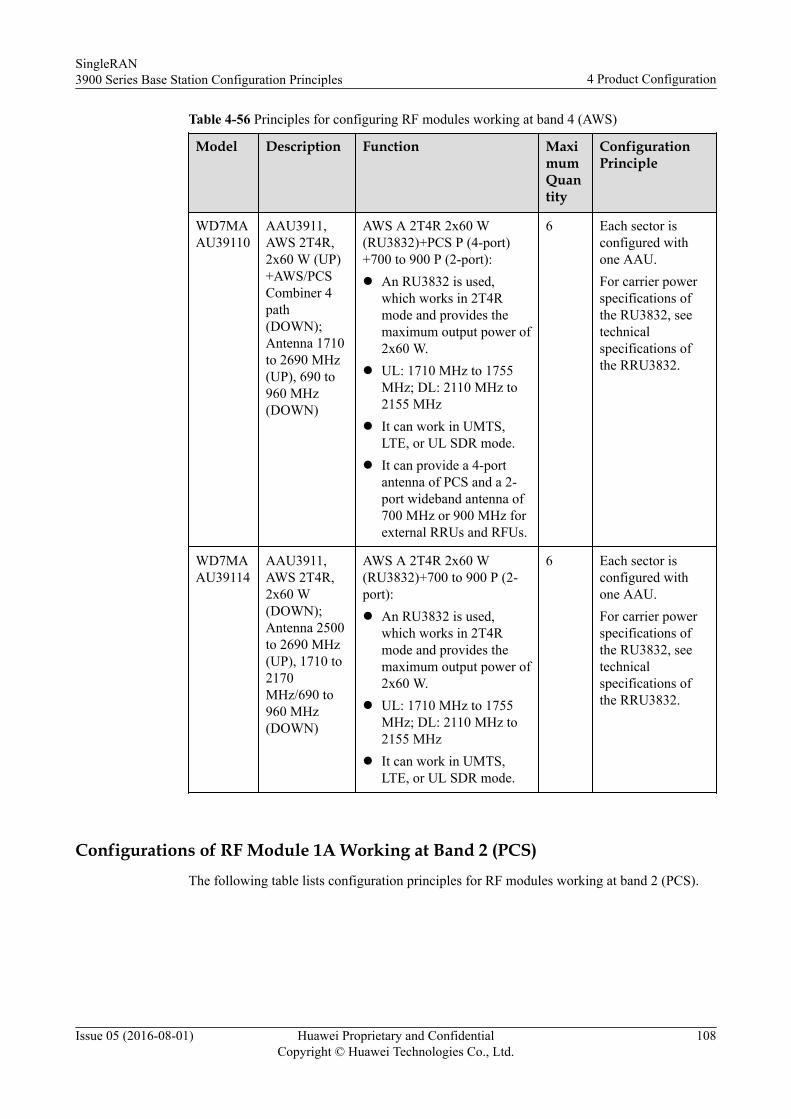
Table 4-56 Principles for configuring RF modules working at band 4 (AWS)
Model Description Function MaximumQuantity
ConfigurationPrinciple
WD7MAAU39110
AAU3911,AWS 2T4R,2x60 W (UP)+AWS/PCSCombiner 4path(DOWN);Antenna 1710to 2690 MHz(UP), 690 to960 MHz(DOWN)
AWS A 2T4R 2x60 W(RU3832)+PCS P (4-port)+700 to 900 P (2-port):l An RU3832 is used,
which works in 2T4Rmode and provides themaximum output power of2x60 W.
l UL: 1710 MHz to 1755MHz; DL: 2110 MHz to2155 MHz
l It can work in UMTS,LTE, or UL SDR mode.
l It can provide a 4-portantenna of PCS and a 2-port wideband antenna of700 MHz or 900 MHz forexternal RRUs and RFUs.
6 Each sector isconfigured withone AAU.For carrier powerspecifications ofthe RU3832, seetechnicalspecifications ofthe RRU3832.
WD7MAAU39114
AAU3911,AWS 2T4R,2x60 W(DOWN);Antenna 2500to 2690 MHz(UP), 1710 to2170MHz/690 to960 MHz(DOWN)
AWS A 2T4R 2x60 W(RU3832)+700 to 900 P (2-port):l An RU3832 is used,
which works in 2T4Rmode and provides themaximum output power of2x60 W.
l UL: 1710 MHz to 1755MHz; DL: 2110 MHz to2155 MHz
l It can work in UMTS,LTE, or UL SDR mode.
6 Each sector isconfigured withone AAU.For carrier powerspecifications ofthe RU3832, seetechnicalspecifications ofthe RRU3832.
Configurations of RF Module 1A Working at Band 2 (PCS)The following table lists configuration principles for RF modules working at band 2 (PCS).
SingleRAN3900 Series Base Station Configuration Principles 4 Product Configuration
Issue 05 (2016-08-01) Huawei Proprietary and ConfidentialCopyright © Huawei Technologies Co., Ltd.
108
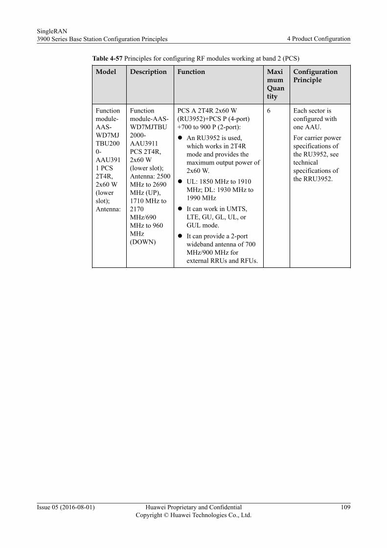
Table 4-57 Principles for configuring RF modules working at band 2 (PCS)
Model Description Function MaximumQuantity
ConfigurationPrinciple
Functionmodule-AAS-WD7MJTBU2000-AAU3911 PCS2T4R,2x60 W(lowerslot);Antenna:
Functionmodule-AAS-WD7MJTBU2000-AAU3911PCS 2T4R,2x60 W(lower slot);Antenna: 2500MHz to 2690MHz (UP),1710 MHz to2170MHz/690MHz to 960MHz(DOWN)
PCS A 2T4R 2x60 W(RU3952)+PCS P (4-port)+700 to 900 P (2-port):l An RU3952 is used,
which works in 2T4Rmode and provides themaximum output power of2x60 W.
l UL: 1850 MHz to 1910MHz; DL: 1930 MHz to1990 MHz
l It can work in UMTS,LTE, GU, GL, UL, orGUL mode.
l It can provide a 2-portwideband antenna of 700MHz/900 MHz forexternal RRUs and RFUs.
6 Each sector isconfigured withone AAU.For carrier powerspecifications ofthe RU3952, seetechnicalspecifications ofthe RRU3952.
SingleRAN3900 Series Base Station Configuration Principles 4 Product Configuration
Issue 05 (2016-08-01) Huawei Proprietary and ConfidentialCopyright © Huawei Technologies Co., Ltd.
109
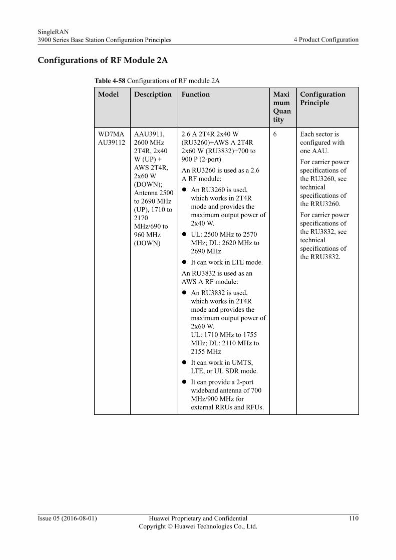
Configurations of RF Module 2A
Table 4-58 Configurations of RF module 2A
Model Description Function MaximumQuantity
ConfigurationPrinciple
WD7MAAU39112
AAU3911,2600 MHz2T4R, 2x40W (UP) +AWS 2T4R,2x60 W(DOWN);Antenna 2500to 2690 MHz(UP), 1710 to2170MHz/690 to960 MHz(DOWN)
2.6 A 2T4R 2x40 W(RU3260)+AWS A 2T4R2x60 W (RU3832)+700 to900 P (2-port)An RU3260 is used as a 2.6A RF module:l An RU3260 is used,
which works in 2T4Rmode and provides themaximum output power of2x40 W.
l UL: 2500 MHz to 2570MHz; DL: 2620 MHz to2690 MHz
l It can work in LTE mode.An RU3832 is used as anAWS A RF module:l An RU3832 is used,
which works in 2T4Rmode and provides themaximum output power of2x60 W.UL: 1710 MHz to 1755MHz; DL: 2110 MHz to2155 MHz
l It can work in UMTS,LTE, or UL SDR mode.
l It can provide a 2-portwideband antenna of 700MHz/900 MHz forexternal RRUs and RFUs.
6 Each sector isconfigured withone AAU.For carrier powerspecifications ofthe RU3260, seetechnicalspecifications ofthe RRU3260.For carrier powerspecifications ofthe RU3832, seetechnicalspecifications ofthe RRU3832.
SingleRAN3900 Series Base Station Configuration Principles 4 Product Configuration
Issue 05 (2016-08-01) Huawei Proprietary and ConfidentialCopyright © Huawei Technologies Co., Ltd.
110
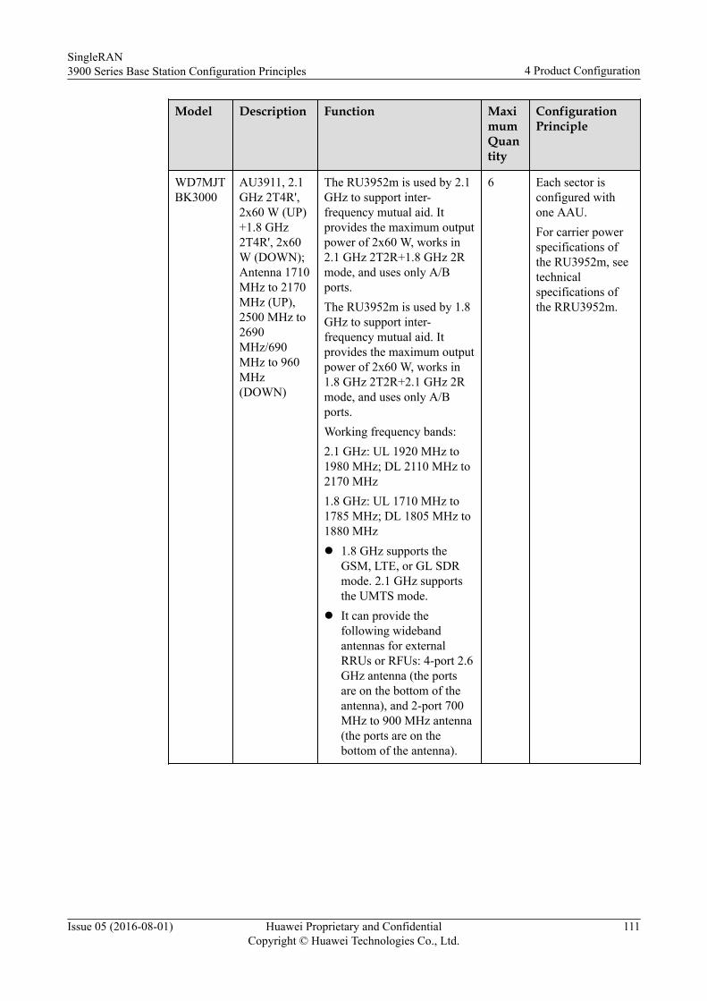
Model Description Function MaximumQuantity
ConfigurationPrinciple
WD7MJTBK3000
AU3911, 2.1GHz 2T4R',2x60 W (UP)+1.8 GHz2T4R', 2x60W (DOWN);Antenna 1710MHz to 2170MHz (UP),2500 MHz to2690MHz/690MHz to 960MHz(DOWN)
The RU3952m is used by 2.1GHz to support inter-frequency mutual aid. Itprovides the maximum outputpower of 2x60 W, works in2.1 GHz 2T2R+1.8 GHz 2Rmode, and uses only A/Bports.The RU3952m is used by 1.8GHz to support inter-frequency mutual aid. Itprovides the maximum outputpower of 2x60 W, works in1.8 GHz 2T2R+2.1 GHz 2Rmode, and uses only A/Bports.Working frequency bands:2.1 GHz: UL 1920 MHz to1980 MHz; DL 2110 MHz to2170 MHz1.8 GHz: UL 1710 MHz to1785 MHz; DL 1805 MHz to1880 MHzl 1.8 GHz supports the
GSM, LTE, or GL SDRmode. 2.1 GHz supportsthe UMTS mode.
l It can provide thefollowing widebandantennas for externalRRUs or RFUs: 4-port 2.6GHz antenna (the portsare on the bottom of theantenna), and 2-port 700MHz to 900 MHz antenna(the ports are on thebottom of the antenna).
6 Each sector isconfigured withone AAU.For carrier powerspecifications ofthe RU3952m, seetechnicalspecifications ofthe RRU3952m.
SingleRAN3900 Series Base Station Configuration Principles 4 Product Configuration
Issue 05 (2016-08-01) Huawei Proprietary and ConfidentialCopyright © Huawei Technologies Co., Ltd.
111
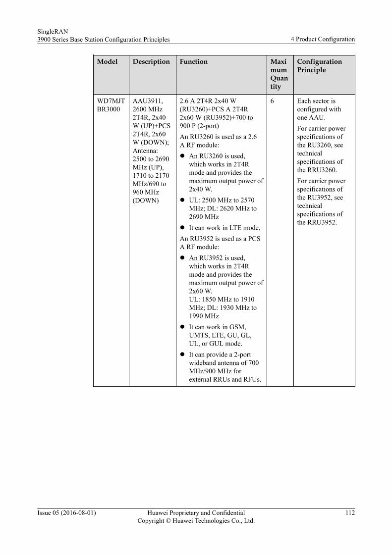
Model Description Function MaximumQuantity
ConfigurationPrinciple
WD7MJTBR3000
AAU3911,2600 MHz2T4R, 2x40W (UP)+PCS2T4R, 2x60W (DOWN);Antenna:2500 to 2690MHz (UP),1710 to 2170MHz/690 to960 MHz(DOWN)
2.6 A 2T4R 2x40 W(RU3260)+PCS A 2T4R2x60 W (RU3952)+700 to900 P (2-port)An RU3260 is used as a 2.6A RF module:l An RU3260 is used,
which works in 2T4Rmode and provides themaximum output power of2x40 W.
l UL: 2500 MHz to 2570MHz; DL: 2620 MHz to2690 MHz
l It can work in LTE mode.An RU3952 is used as a PCSA RF module:l An RU3952 is used,
which works in 2T4Rmode and provides themaximum output power of2x60 W.UL: 1850 MHz to 1910MHz; DL: 1930 MHz to1990 MHz
l It can work in GSM,UMTS, LTE, GU, GL,UL, or GUL mode.
l It can provide a 2-portwideband antenna of 700MHz/900 MHz forexternal RRUs and RFUs.
6 Each sector isconfigured withone AAU.For carrier powerspecifications ofthe RU3260, seetechnicalspecifications ofthe RRU3260.For carrier powerspecifications ofthe RU3952, seetechnicalspecifications ofthe RRU3952.
SingleRAN3900 Series Base Station Configuration Principles 4 Product Configuration
Issue 05 (2016-08-01) Huawei Proprietary and ConfidentialCopyright © Huawei Technologies Co., Ltd.
112
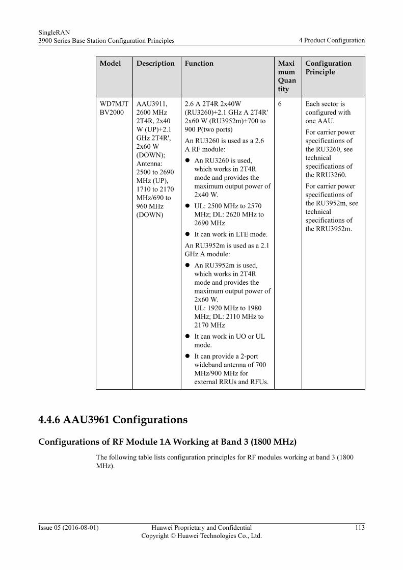
Model Description Function MaximumQuantity
ConfigurationPrinciple
WD7MJTBV2000
AAU3911,2600 MHz2T4R, 2x40W (UP)+2.1GHz 2T4R',2x60 W(DOWN);Antenna:2500 to 2690MHz (UP),1710 to 2170MHz/690 to960 MHz(DOWN)
2.6 A 2T4R 2x40W(RU3260)+2.1 GHz A 2T4R'2x60 W (RU3952m)+700 to900 P(two ports)An RU3260 is used as a 2.6A RF module:l An RU3260 is used,
which works in 2T4Rmode and provides themaximum output power of2x40 W.
l UL: 2500 MHz to 2570MHz; DL: 2620 MHz to2690 MHz
l It can work in LTE mode.An RU3952m is used as a 2.1GHz A module:l An RU3952m is used,
which works in 2T4Rmode and provides themaximum output power of2x60 W.UL: 1920 MHz to 1980MHz; DL: 2110 MHz to2170 MHz
l It can work in UO or ULmode.
l It can provide a 2-portwideband antenna of 700MHz/900 MHz forexternal RRUs and RFUs.
6 Each sector isconfigured withone AAU.For carrier powerspecifications ofthe RU3260, seetechnicalspecifications ofthe RRU3260.For carrier powerspecifications ofthe RU3952m, seetechnicalspecifications ofthe RRU3952m.
4.4.6 AAU3961 Configurations
Configurations of RF Module 1A Working at Band 3 (1800 MHz)The following table lists configuration principles for RF modules working at band 3 (1800MHz).
SingleRAN3900 Series Base Station Configuration Principles 4 Product Configuration
Issue 05 (2016-08-01) Huawei Proprietary and ConfidentialCopyright © Huawei Technologies Co., Ltd.
113
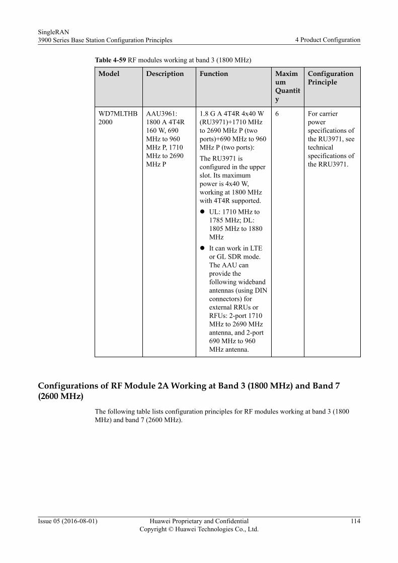
Table 4-59 RF modules working at band 3 (1800 MHz)
Model Description Function MaximumQuantity
ConfigurationPrinciple
WD7MLTHB2000
AAU3961:1800 A 4T4R160 W, 690MHz to 960MHz P, 1710MHz to 2690MHz P
1.8 G A 4T4R 4x40 W(RU3971)+1710 MHzto 2690 MHz P (twoports)+690 MHz to 960MHz P (two ports):The RU3971 isconfigured in the upperslot. Its maximumpower is 4x40 W,working at 1800 MHzwith 4T4R supported.l UL: 1710 MHz to
1785 MHz; DL:1805 MHz to 1880MHz
l It can work in LTEor GL SDR mode.The AAU canprovide thefollowing widebandantennas (using DINconnectors) forexternal RRUs orRFUs: 2-port 1710MHz to 2690 MHzantenna, and 2-port690 MHz to 960MHz antenna.
6 For carrierpowerspecifications ofthe RU3971, seetechnicalspecifications ofthe RRU3971.
Configurations of RF Module 2A Working at Band 3 (1800 MHz) and Band 7(2600 MHz)
The following table lists configuration principles for RF modules working at band 3 (1800MHz) and band 7 (2600 MHz).
SingleRAN3900 Series Base Station Configuration Principles 4 Product Configuration
Issue 05 (2016-08-01) Huawei Proprietary and ConfidentialCopyright © Huawei Technologies Co., Ltd.
114
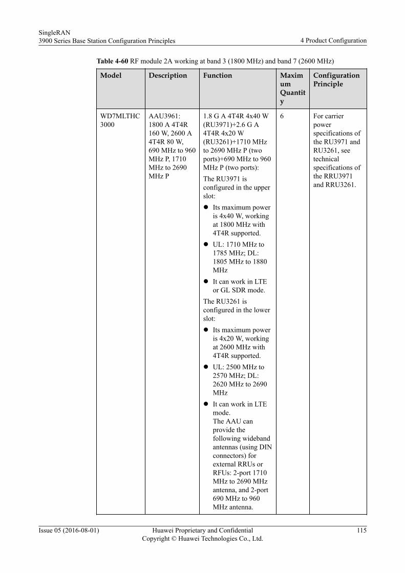
Table 4-60 RF module 2A working at band 3 (1800 MHz) and band 7 (2600 MHz)
Model Description Function MaximumQuantity
ConfigurationPrinciple
WD7MLTHC3000
AAU3961:1800 A 4T4R160 W, 2600 A4T4R 80 W,690 MHz to 960MHz P, 1710MHz to 2690MHz P
1.8 G A 4T4R 4x40 W(RU3971)+2.6 G A4T4R 4x20 W(RU3261)+1710 MHzto 2690 MHz P (twoports)+690 MHz to 960MHz P (two ports):The RU3971 isconfigured in the upperslot:l Its maximum power
is 4x40 W, workingat 1800 MHz with4T4R supported.
l UL: 1710 MHz to1785 MHz; DL:1805 MHz to 1880MHz
l It can work in LTEor GL SDR mode.
The RU3261 isconfigured in the lowerslot:l Its maximum power
is 4x20 W, workingat 2600 MHz with4T4R supported.
l UL: 2500 MHz to2570 MHz; DL:2620 MHz to 2690MHz
l It can work in LTEmode.The AAU canprovide thefollowing widebandantennas (using DINconnectors) forexternal RRUs orRFUs: 2-port 1710MHz to 2690 MHzantenna, and 2-port690 MHz to 960MHz antenna.
6 For carrierpowerspecifications ofthe RU3971 andRU3261, seetechnicalspecifications ofthe RRU3971and RRU3261.
SingleRAN3900 Series Base Station Configuration Principles 4 Product Configuration
Issue 05 (2016-08-01) Huawei Proprietary and ConfidentialCopyright © Huawei Technologies Co., Ltd.
115
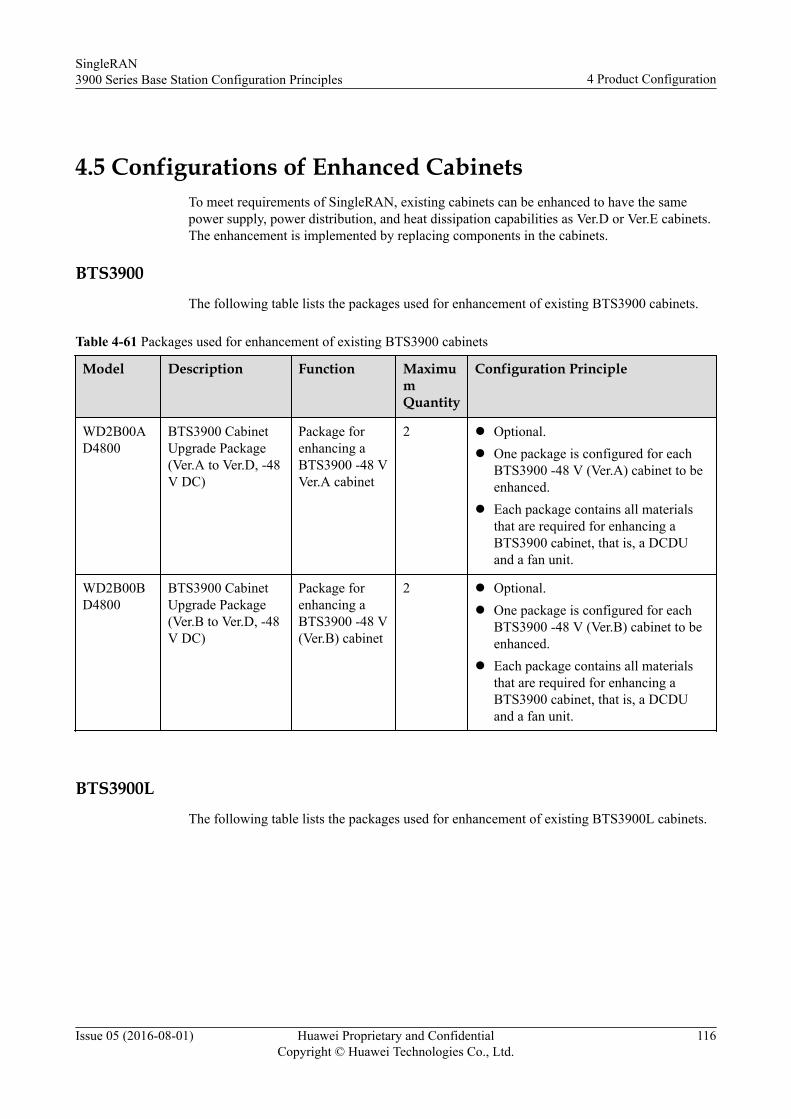
4.5 Configurations of Enhanced CabinetsTo meet requirements of SingleRAN, existing cabinets can be enhanced to have the samepower supply, power distribution, and heat dissipation capabilities as Ver.D or Ver.E cabinets.The enhancement is implemented by replacing components in the cabinets.
BTS3900The following table lists the packages used for enhancement of existing BTS3900 cabinets.
Table 4-61 Packages used for enhancement of existing BTS3900 cabinets
Model Description Function MaximumQuantity
Configuration Principle
WD2B00AD4800
BTS3900 CabinetUpgrade Package(Ver.A to Ver.D, -48V DC)
Package forenhancing aBTS3900 -48 VVer.A cabinet
2 l Optional.l One package is configured for each
BTS3900 -48 V (Ver.A) cabinet to beenhanced.
l Each package contains all materialsthat are required for enhancing aBTS3900 cabinet, that is, a DCDUand a fan unit.
WD2B00BD4800
BTS3900 CabinetUpgrade Package(Ver.B to Ver.D, -48V DC)
Package forenhancing aBTS3900 -48 V(Ver.B) cabinet
2 l Optional.l One package is configured for each
BTS3900 -48 V (Ver.B) cabinet to beenhanced.
l Each package contains all materialsthat are required for enhancing aBTS3900 cabinet, that is, a DCDUand a fan unit.
BTS3900LThe following table lists the packages used for enhancement of existing BTS3900L cabinets.
SingleRAN3900 Series Base Station Configuration Principles 4 Product Configuration
Issue 05 (2016-08-01) Huawei Proprietary and ConfidentialCopyright © Huawei Technologies Co., Ltd.
116
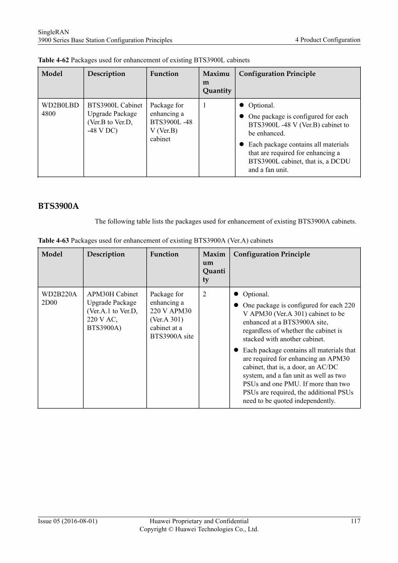
Table 4-62 Packages used for enhancement of existing BTS3900L cabinets
Model Description Function MaximumQuantity
Configuration Principle
WD2B0LBD4800
BTS3900L CabinetUpgrade Package(Ver.B to Ver.D,-48 V DC)
Package forenhancing aBTS3900L -48V (Ver.B)cabinet
1 l Optional.l One package is configured for each
BTS3900L -48 V (Ver.B) cabinet tobe enhanced.
l Each package contains all materialsthat are required for enhancing aBTS3900L cabinet, that is, a DCDUand a fan unit.
BTS3900AThe following table lists the packages used for enhancement of existing BTS3900A cabinets.
Table 4-63 Packages used for enhancement of existing BTS3900A (Ver.A) cabinets
Model Description Function MaximumQuantity
Configuration Principle
WD2B220A2D00
APM30H CabinetUpgrade Package(Ver.A.1 to Ver.D,220 V AC,BTS3900A)
Package forenhancing a220 V APM30(Ver.A 301)cabinet at aBTS3900A site
2 l Optional.l One package is configured for each 220
V APM30 (Ver.A 301) cabinet to beenhanced at a BTS3900A site,regardless of whether the cabinet isstacked with another cabinet.
l Each package contains all materials thatare required for enhancing an APM30cabinet, that is, a door, an AC/DCsystem, and a fan unit as well as twoPSUs and one PMU. If more than twoPSUs are required, the additional PSUsneed to be quoted independently.
SingleRAN3900 Series Base Station Configuration Principles 4 Product Configuration
Issue 05 (2016-08-01) Huawei Proprietary and ConfidentialCopyright © Huawei Technologies Co., Ltd.
117
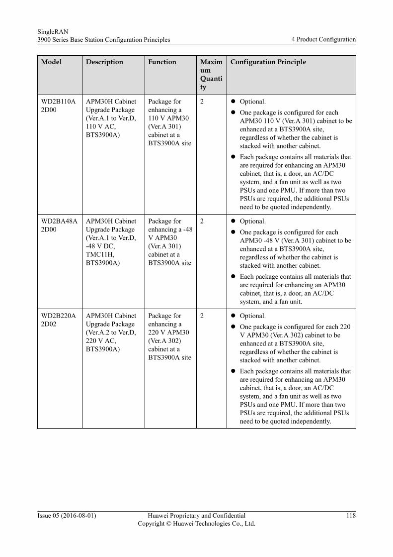
Model Description Function MaximumQuantity
Configuration Principle
WD2B110A2D00
APM30H CabinetUpgrade Package(Ver.A.1 to Ver.D,110 V AC,BTS3900A)
Package forenhancing a110 V APM30(Ver.A 301)cabinet at aBTS3900A site
2 l Optional.l One package is configured for each
APM30 110 V (Ver.A 301) cabinet to beenhanced at a BTS3900A site,regardless of whether the cabinet isstacked with another cabinet.
l Each package contains all materials thatare required for enhancing an APM30cabinet, that is, a door, an AC/DCsystem, and a fan unit as well as twoPSUs and one PMU. If more than twoPSUs are required, the additional PSUsneed to be quoted independently.
WD2BA48A2D00
APM30H CabinetUpgrade Package(Ver.A.1 to Ver.D,-48 V DC,TMC11H,BTS3900A)
Package forenhancing a -48V APM30(Ver.A 301)cabinet at aBTS3900A site
2 l Optional.l One package is configured for each
APM30 -48 V (Ver.A 301) cabinet to beenhanced at a BTS3900A site,regardless of whether the cabinet isstacked with another cabinet.
l Each package contains all materials thatare required for enhancing an APM30cabinet, that is, a door, an AC/DCsystem, and a fan unit.
WD2B220A2D02
APM30H CabinetUpgrade Package(Ver.A.2 to Ver.D,220 V AC,BTS3900A)
Package forenhancing a220 V APM30(Ver.A 302)cabinet at aBTS3900A site
2 l Optional.l One package is configured for each 220
V APM30 (Ver.A 302) cabinet to beenhanced at a BTS3900A site,regardless of whether the cabinet isstacked with another cabinet.
l Each package contains all materials thatare required for enhancing an APM30cabinet, that is, a door, an AC/DCsystem, and a fan unit as well as twoPSUs and one PMU. If more than twoPSUs are required, the additional PSUsneed to be quoted independently.
SingleRAN3900 Series Base Station Configuration Principles 4 Product Configuration
Issue 05 (2016-08-01) Huawei Proprietary and ConfidentialCopyright © Huawei Technologies Co., Ltd.
118
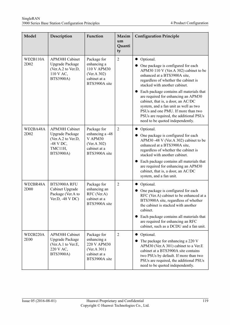
Model Description Function MaximumQuantity
Configuration Principle
WD2B110A2D02
APM30H CabinetUpgrade Package(Ver.A.2 to Ver.D,110 V AC,BTS3900A)
Package forenhancing a110 V APM30(Ver.A 302)cabinet at aBTS3900A site
2 l Optional.l One package is configured for each
APM30 110 V (Ver.A 302) cabinet to beenhanced at a BTS3900A site,regardless of whether the cabinet isstacked with another cabinet.
l Each package contains all materials thatare required for enhancing an APM30cabinet, that is, a door, an AC/DCsystem, and a fan unit as well as twoPSUs and one PMU. If more than twoPSUs are required, the additional PSUsneed to be quoted independently.
WD2BA48A2D02
APM30H CabinetUpgrade Package(Ver.A.2 to Ver.D,-48 V DC,TMC11H,BTS3900A)
Package forenhancing a -48V APM30(Ver.A 302)cabinet at aBTS3900A site
2 l Optional.l One package is configured for each
APM30 -48 V (Ver.A 302) cabinet to beenhanced at a BTS3900A site,regardless of whether the cabinet isstacked with another cabinet.
l Each package contains all materials thatare required for enhancing an APM30cabinet, that is, a door, an AC/DCsystem, and a fan unit.
WD2BR48A2D00
BTS3900A RFUCabinet UpgradePackage (Ver.A toVer.D, -48 V DC)
Package forenhancing anRFC (Ver.A)cabinet at aBTS3900A site
2 l Optional.l One package is configured for each
RFC (Ver.A) cabinet to be enhanced at aBTS3900A site, regardless of whetherthe cabinet is stacked with anothercabinet.
l Each package contains all materials thatare required for enhancing an RFCcabinet, such as a DCDU and a fan unit.
WD2B220A2E00
APM30H CabinetUpgrade Package(Ver.A.1 to Ver.E,220 V AC,BTS3900A)
Package forenhancing a220 V APM30(Ver.A 301)cabinet at aBTS3900A site
2 l Optional.l The package for enhancing a 220 V
APM30 (Ver.A 301) cabinet to a Ver.Ecabinet at a BTS3900A site containstwo PSUs by default. If more than twoPSUs are required, the additional PSUsneed to be quoted independently.
SingleRAN3900 Series Base Station Configuration Principles 4 Product Configuration
Issue 05 (2016-08-01) Huawei Proprietary and ConfidentialCopyright © Huawei Technologies Co., Ltd.
119
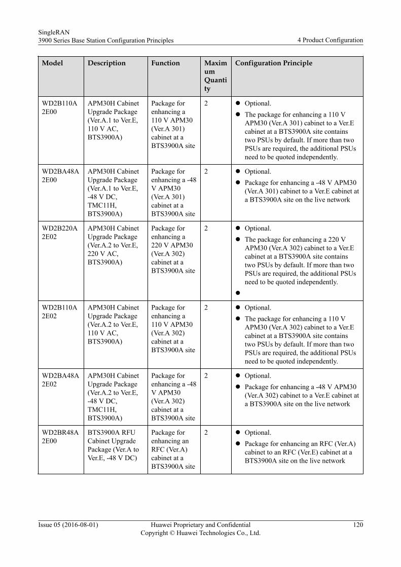
Model Description Function MaximumQuantity
Configuration Principle
WD2B110A2E00
APM30H CabinetUpgrade Package(Ver.A.1 to Ver.E,110 V AC,BTS3900A)
Package forenhancing a110 V APM30(Ver.A 301)cabinet at aBTS3900A site
2 l Optional.l The package for enhancing a 110 V
APM30 (Ver.A 301) cabinet to a Ver.Ecabinet at a BTS3900A site containstwo PSUs by default. If more than twoPSUs are required, the additional PSUsneed to be quoted independently.
WD2BA48A2E00
APM30H CabinetUpgrade Package(Ver.A.1 to Ver.E,-48 V DC,TMC11H,BTS3900A)
Package forenhancing a -48V APM30(Ver.A 301)cabinet at aBTS3900A site
2 l Optional.l Package for enhancing a -48 V APM30
(Ver.A 301) cabinet to a Ver.E cabinet ata BTS3900A site on the live network
WD2B220A2E02
APM30H CabinetUpgrade Package(Ver.A.2 to Ver.E,220 V AC,BTS3900A)
Package forenhancing a220 V APM30(Ver.A 302)cabinet at aBTS3900A site
2 l Optional.l The package for enhancing a 220 V
APM30 (Ver.A 302) cabinet to a Ver.Ecabinet at a BTS3900A site containstwo PSUs by default. If more than twoPSUs are required, the additional PSUsneed to be quoted independently.
l
WD2B110A2E02
APM30H CabinetUpgrade Package(Ver.A.2 to Ver.E,110 V AC,BTS3900A)
Package forenhancing a110 V APM30(Ver.A 302)cabinet at aBTS3900A site
2 l Optional.l The package for enhancing a 110 V
APM30 (Ver.A 302) cabinet to a Ver.Ecabinet at a BTS3900A site containstwo PSUs by default. If more than twoPSUs are required, the additional PSUsneed to be quoted independently.
WD2BA48A2E02
APM30H CabinetUpgrade Package(Ver.A.2 to Ver.E,-48 V DC,TMC11H,BTS3900A)
Package forenhancing a -48V APM30(Ver.A 302)cabinet at aBTS3900A site
2 l Optional.l Package for enhancing a -48 V APM30
(Ver.A 302) cabinet to a Ver.E cabinet ata BTS3900A site on the live network
WD2BR48A2E00
BTS3900A RFUCabinet UpgradePackage (Ver.A toVer.E, -48 V DC)
Package forenhancing anRFC (Ver.A)cabinet at aBTS3900A site
2 l Optional.l Package for enhancing an RFC (Ver.A)
cabinet to an RFC (Ver.E) cabinet at aBTS3900A site on the live network
SingleRAN3900 Series Base Station Configuration Principles 4 Product Configuration
Issue 05 (2016-08-01) Huawei Proprietary and ConfidentialCopyright © Huawei Technologies Co., Ltd.
120
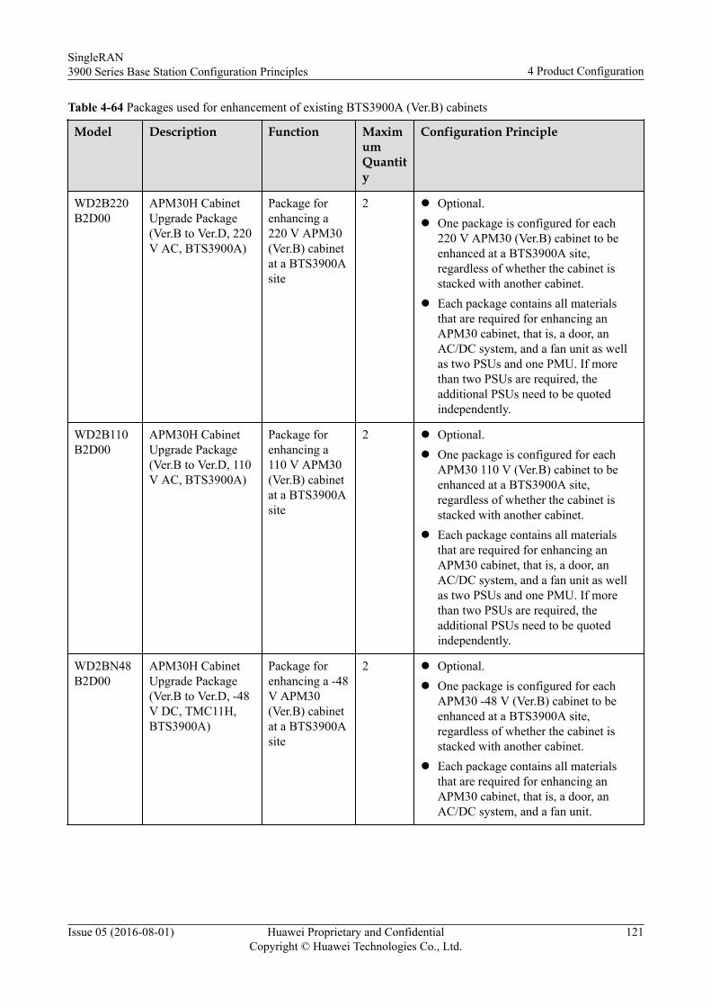
Table 4-64 Packages used for enhancement of existing BTS3900A (Ver.B) cabinets
Model Description Function MaximumQuantity
Configuration Principle
WD2B220B2D00
APM30H CabinetUpgrade Package(Ver.B to Ver.D, 220V AC, BTS3900A)
Package forenhancing a220 V APM30(Ver.B) cabinetat a BTS3900Asite
2 l Optional.l One package is configured for each
220 V APM30 (Ver.B) cabinet to beenhanced at a BTS3900A site,regardless of whether the cabinet isstacked with another cabinet.
l Each package contains all materialsthat are required for enhancing anAPM30 cabinet, that is, a door, anAC/DC system, and a fan unit as wellas two PSUs and one PMU. If morethan two PSUs are required, theadditional PSUs need to be quotedindependently.
WD2B110B2D00
APM30H CabinetUpgrade Package(Ver.B to Ver.D, 110V AC, BTS3900A)
Package forenhancing a110 V APM30(Ver.B) cabinetat a BTS3900Asite
2 l Optional.l One package is configured for each
APM30 110 V (Ver.B) cabinet to beenhanced at a BTS3900A site,regardless of whether the cabinet isstacked with another cabinet.
l Each package contains all materialsthat are required for enhancing anAPM30 cabinet, that is, a door, anAC/DC system, and a fan unit as wellas two PSUs and one PMU. If morethan two PSUs are required, theadditional PSUs need to be quotedindependently.
WD2BN48B2D00
APM30H CabinetUpgrade Package(Ver.B to Ver.D, -48V DC, TMC11H,BTS3900A)
Package forenhancing a -48V APM30(Ver.B) cabinetat a BTS3900Asite
2 l Optional.l One package is configured for each
APM30 -48 V (Ver.B) cabinet to beenhanced at a BTS3900A site,regardless of whether the cabinet isstacked with another cabinet.
l Each package contains all materialsthat are required for enhancing anAPM30 cabinet, that is, a door, anAC/DC system, and a fan unit.
SingleRAN3900 Series Base Station Configuration Principles 4 Product Configuration
Issue 05 (2016-08-01) Huawei Proprietary and ConfidentialCopyright © Huawei Technologies Co., Ltd.
121
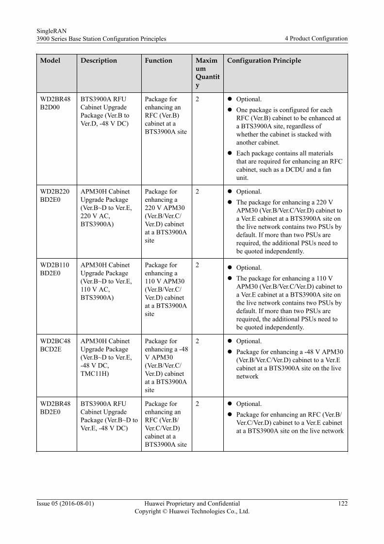
Model Description Function MaximumQuantity
Configuration Principle
WD2BR48B2D00
BTS3900A RFUCabinet UpgradePackage (Ver.B toVer.D, -48 V DC)
Package forenhancing anRFC (Ver.B)cabinet at aBTS3900A site
2 l Optional.l One package is configured for each
RFC (Ver.B) cabinet to be enhanced ata BTS3900A site, regardless ofwhether the cabinet is stacked withanother cabinet.
l Each package contains all materialsthat are required for enhancing an RFCcabinet, such as a DCDU and a fanunit.
WD2B220BD2E0
APM30H CabinetUpgrade Package(Ver.B~D to Ver.E,220 V AC,BTS3900A)
Package forenhancing a220 V APM30(Ver.B/Ver.C/Ver.D) cabinetat a BTS3900Asite
2 l Optional.l The package for enhancing a 220 V
APM30 (Ver.B/Ver.C/Ver.D) cabinet toa Ver.E cabinet at a BTS3900A site onthe live network contains two PSUs bydefault. If more than two PSUs arerequired, the additional PSUs need tobe quoted independently.
WD2B110BD2E0
APM30H CabinetUpgrade Package(Ver.B~D to Ver.E,110 V AC,BTS3900A)
Package forenhancing a110 V APM30(Ver.B/Ver.C/Ver.D) cabinetat a BTS3900Asite
2 l Optional.l The package for enhancing a 110 V
APM30 (Ver.B/Ver.C/Ver.D) cabinet toa Ver.E cabinet at a BTS3900A site onthe live network contains two PSUs bydefault. If more than two PSUs arerequired, the additional PSUs need tobe quoted independently.
WD2BC48BCD2E
APM30H CabinetUpgrade Package(Ver.B~D to Ver.E,-48 V DC,TMC11H)
Package forenhancing a -48V APM30(Ver.B/Ver.C/Ver.D) cabinetat a BTS3900Asite
2 l Optional.l Package for enhancing a -48 V APM30
(Ver.B/Ver.C/Ver.D) cabinet to a Ver.Ecabinet at a BTS3900A site on the livenetwork
WD2BR48BD2E0
BTS3900A RFUCabinet UpgradePackage (Ver.B~D toVer.E, -48 V DC)
Package forenhancing anRFC (Ver.B/Ver.C/Ver.D)cabinet at aBTS3900A site
2 l Optional.l Package for enhancing an RFC (Ver.B/
Ver.C/Ver.D) cabinet to a Ver.E cabinetat a BTS3900A site on the live network
SingleRAN3900 Series Base Station Configuration Principles 4 Product Configuration
Issue 05 (2016-08-01) Huawei Proprietary and ConfidentialCopyright © Huawei Technologies Co., Ltd.
122

Table 4-65 Packages used for enhancement of existing BTS3900A (Ver.C) cabinets
Model Description Function MaximumQuantity
Configuration Principle
WD2B220C2D00
APM30H CabinetUpgrade Package(Ver.C to Ver.D, 220V AC, BTS3900A)
Package forenhancing a220 V APM30(Ver.C) cabinetat a BTS3900Asite
2 l Optional.l One package is configured for each
220 V APM30 (Ver.C) cabinet to beenhanced at a BTS3900A site,regardless of whether the cabinet isstacked with another cabinet.
l Each package contains all materialsthat are required for enhancing anAPM30 cabinet, that is, a door, anAC/DC system, and a fan unit as wellas two PSUs and one PMU. If morethan two PSUs are required, theadditional PSUs need to be quotedindependently.
WD2B110C2D00
APM30H CabinetUpgrade Package(Ver.C to Ver.D, 110V AC, BTS3900A)
Package forenhancing a110 V APM30(Ver.C) cabinetat a BTS3900Asite
2 l Optional.l One package is configured for each
APM30 110 V (Ver.C) cabinet to beenhanced at a BTS3900A site,regardless of whether the cabinet isstacked with another cabinet.
l Each package contains all materialsthat are required for enhancing anAPM30 cabinet, that is, a door, anAC/DC system, and a fan unit as wellas two PSUs and one PMU. If morethan two PSUs are required, theadditional PSUs need to be quotedindependently.
WD2BC48C2D00
APM30H CabinetUpgrade Package(Ver.C to Ver.D, -48V DC, TMC11H,BTS3900A)
Package forenhancing a -48V APM30(Ver.C) cabinetat a BTS3900Asite
2 l Optional.l One package is configured for each
APM30 -48 V (Ver.C) cabinet to beenhanced at a BTS3900A site,regardless of whether the cabinet isstacked with another cabinet.
l Each package contains all materialsthat are required for enhancing anAPM30 cabinet, that is, a door, anAC/DC system, and a fan unit.
SingleRAN3900 Series Base Station Configuration Principles 4 Product Configuration
Issue 05 (2016-08-01) Huawei Proprietary and ConfidentialCopyright © Huawei Technologies Co., Ltd.
123
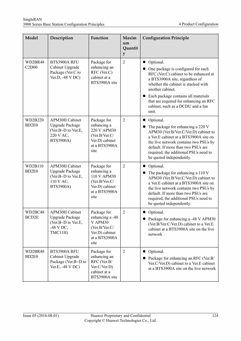
Model Description Function MaximumQuantity
Configuration Principle
WD2BR48C2D00
BTS3900A RFUCabinet UpgradePackage (Ver.C toVer.D, -48 V DC)
Package forenhancing anRFC (Ver.C)cabinet at aBTS3900A site
2 l Optional.l One package is configured for each
RFC (Ver.C) cabinet to be enhanced ata BTS3900A site, regardless ofwhether the cabinet is stacked withanother cabinet.
l Each package contains all materialsthat are required for enhancing an RFCcabinet, such as a DCDU and a fanunit.
WD2B220BD2E0
APM30H CabinetUpgrade Package(Ver.B~D to Ver.E,220 V AC,BTS3900A)
Package forenhancing a220 V APM30(Ver.B/Ver.C/Ver.D) cabinetat a BTS3900Asite
2 l Optional.l The package for enhancing a 220 V
APM30 (Ver.B/Ver.C/Ver.D) cabinet toa Ver.E cabinet at a BTS3900A site onthe live network contains two PSUs bydefault. If more than two PSUs arerequired, the additional PSUs need tobe quoted independently.
WD2B110BD2E0
APM30H CabinetUpgrade Package(Ver.B~D to Ver.E,110 V AC,BTS3900A)
Package forenhancing a110 V APM30(Ver.B/Ver.C/Ver.D) cabinetat a BTS3900Asite
2 l Optional.l The package for enhancing a 110 V
APM30 (Ver.B/Ver.C/Ver.D) cabinet toa Ver.E cabinet at a BTS3900A site onthe live network contains two PSUs bydefault. If more than two PSUs arerequired, the additional PSUs need tobe quoted independently.
WD2BC48BCD2E
APM30H CabinetUpgrade Package(Ver.B~D to Ver.E,-48 V DC,TMC11H)
Package forenhancing a -48V APM30(Ver.B/Ver.C/Ver.D) cabinetat a BTS3900Asite
2 l Optional.l Package for enhancing a -48 V APM30
(Ver.B/Ver.C/Ver.D) cabinet to a Ver.Ecabinet at a BTS3900A site on the livenetwork
WD2BR48BD2E0
BTS3900A RFUCabinet UpgradePackage (Ver.B~D toVer.E, -48 V DC)
Package forenhancing anRFC (Ver.B/Ver.C/Ver.D)cabinet at aBTS3900A site
2 l Optional.l Package for enhancing an RFC (Ver.B/
Ver.C/Ver.D) cabinet to a Ver.E cabinetat a BTS3900A site on the live network
SingleRAN3900 Series Base Station Configuration Principles 4 Product Configuration
Issue 05 (2016-08-01) Huawei Proprietary and ConfidentialCopyright © Huawei Technologies Co., Ltd.
124
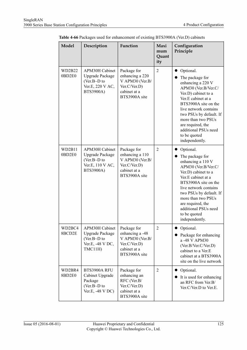
Table 4-66 Packages used for enhancement of existing BTS3900A (Ver.D) cabinets
Model Description Function MaximumQuantity
ConfigurationPrinciple
WD2B220BD2E0
APM30H CabinetUpgrade Package(Ver.B~D toVer.E, 220 V AC,BTS3900A)
Package forenhancing a 220V APM30 (Ver.B/Ver.C/Ver.D)cabinet at aBTS3900A site
2 l Optional.l The package for
enhancing a 220 VAPM30 (Ver.B/Ver.C/Ver.D) cabinet to aVer.E cabinet at aBTS3900A site on thelive network containstwo PSUs by default. Ifmore than two PSUsare required, theadditional PSUs needto be quotedindependently.
WD2B110BD2E0
APM30H CabinetUpgrade Package(Ver.B~D toVer.E, 110 V AC,BTS3900A)
Package forenhancing a 110V APM30 (Ver.B/Ver.C/Ver.D)cabinet at aBTS3900A site
2 l Optional.l The package for
enhancing a 110 VAPM30 (Ver.B/Ver.C/Ver.D) cabinet to aVer.E cabinet at aBTS3900A site on thelive network containstwo PSUs by default. Ifmore than two PSUsare required, theadditional PSUs needto be quotedindependently.
WD2BC48BCD2E
APM30H CabinetUpgrade Package(Ver.B~D toVer.E, -48 V DC,TMC11H)
Package forenhancing a -48V APM30 (Ver.B/Ver.C/Ver.D)cabinet at aBTS3900A site
2 l Optional.l Package for enhancing
a -48 V APM30(Ver.B/Ver.C/Ver.D)cabinet to a Ver.Ecabinet at a BTS3900Asite on the live network
WD2BR48BD2E0
BTS3900A RFUCabinet UpgradePackage(Ver.B~D toVer.E, -48 V DC)
Package forenhancing anRFC (Ver.B/Ver.C/Ver.D)cabinet at aBTS3900A site
2 l Optional.l It is used for enhancing
an RFC from Ver.B/Ver.C/Ver.D to Ver.E.
SingleRAN3900 Series Base Station Configuration Principles 4 Product Configuration
Issue 05 (2016-08-01) Huawei Proprietary and ConfidentialCopyright © Huawei Technologies Co., Ltd.
125
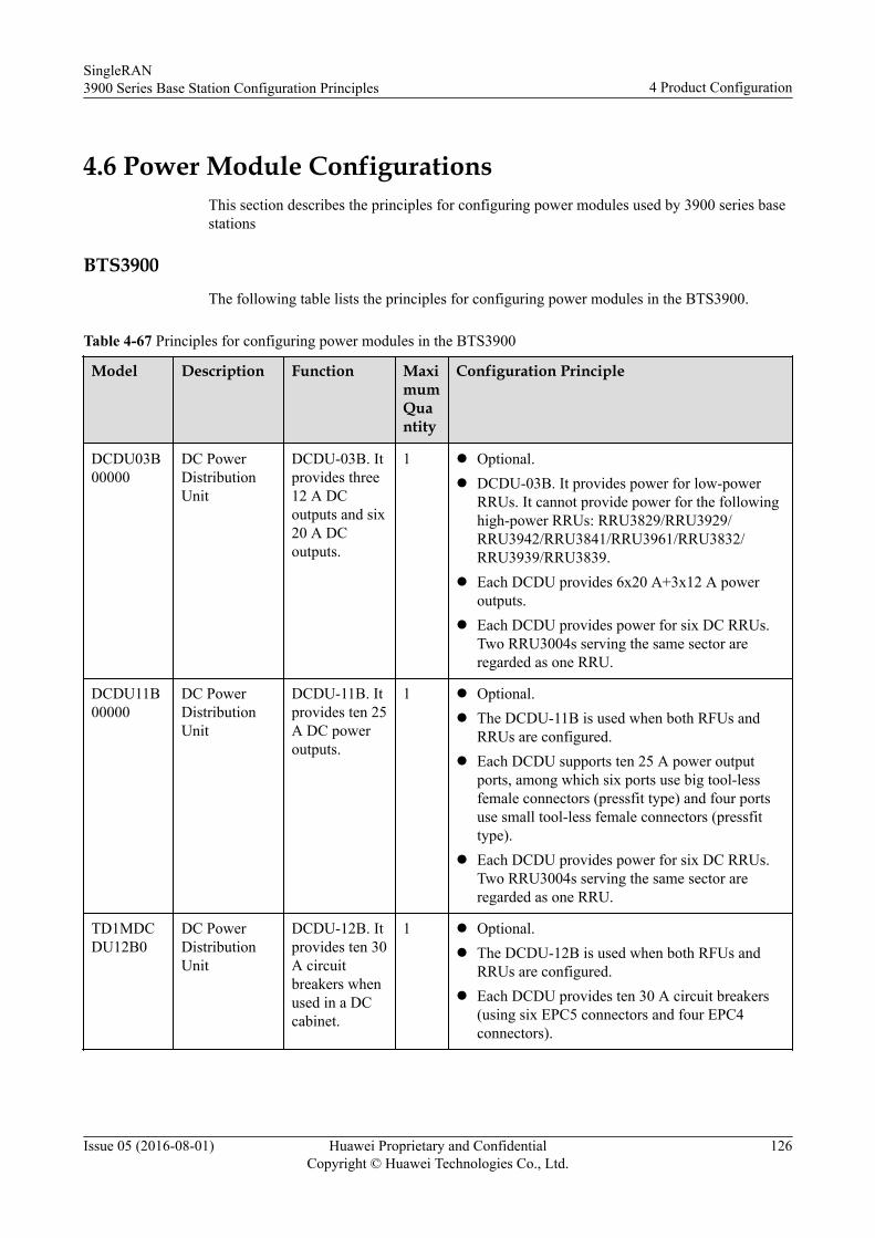
4.6 Power Module ConfigurationsThis section describes the principles for configuring power modules used by 3900 series basestations
BTS3900The following table lists the principles for configuring power modules in the BTS3900.
Table 4-67 Principles for configuring power modules in the BTS3900
Model Description Function MaximumQuantity
Configuration Principle
DCDU03B00000
DC PowerDistributionUnit
DCDU-03B. Itprovides three12 A DCoutputs and six20 A DCoutputs.
1 l Optional.l DCDU-03B. It provides power for low-power
RRUs. It cannot provide power for the followinghigh-power RRUs: RRU3829/RRU3929/RRU3942/RRU3841/RRU3961/RRU3832/RRU3939/RRU3839.
l Each DCDU provides 6x20 A+3x12 A poweroutputs.
l Each DCDU provides power for six DC RRUs.Two RRU3004s serving the same sector areregarded as one RRU.
DCDU11B00000
DC PowerDistributionUnit
DCDU-11B. Itprovides ten 25A DC poweroutputs.
1 l Optional.l The DCDU-11B is used when both RFUs and
RRUs are configured.l Each DCDU supports ten 25 A power output
ports, among which six ports use big tool-lessfemale connectors (pressfit type) and four portsuse small tool-less female connectors (pressfittype).
l Each DCDU provides power for six DC RRUs.Two RRU3004s serving the same sector areregarded as one RRU.
TD1MDCDU12B0
DC PowerDistributionUnit
DCDU-12B. Itprovides ten 30A circuitbreakers whenused in a DCcabinet.
1 l Optional.l The DCDU-12B is used when both RFUs and
RRUs are configured.l Each DCDU provides ten 30 A circuit breakers
(using six EPC5 connectors and four EPC4connectors).
SingleRAN3900 Series Base Station Configuration Principles 4 Product Configuration
Issue 05 (2016-08-01) Huawei Proprietary and ConfidentialCopyright © Huawei Technologies Co., Ltd.
126
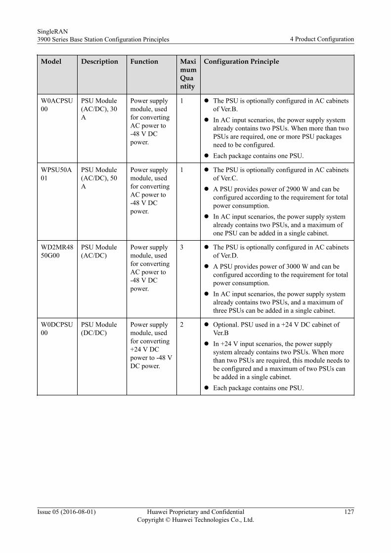
Model Description Function MaximumQuantity
Configuration Principle
W0ACPSU00
PSU Module(AC/DC), 30A
Power supplymodule, usedfor convertingAC power to-48 V DCpower.
1 l The PSU is optionally configured in AC cabinetsof Ver.B.
l In AC input scenarios, the power supply systemalready contains two PSUs. When more than twoPSUs are required, one or more PSU packagesneed to be configured.
l Each package contains one PSU.
WPSU50A01
PSU Module(AC/DC), 50A
Power supplymodule, usedfor convertingAC power to-48 V DCpower.
1 l The PSU is optionally configured in AC cabinetsof Ver.C.
l A PSU provides power of 2900 W and can beconfigured according to the requirement for totalpower consumption.
l In AC input scenarios, the power supply systemalready contains two PSUs, and a maximum ofone PSU can be added in a single cabinet.
WD2MR4850G00
PSU Module(AC/DC)
Power supplymodule, usedfor convertingAC power to-48 V DCpower.
3 l The PSU is optionally configured in AC cabinetsof Ver.D.
l A PSU provides power of 3000 W and can beconfigured according to the requirement for totalpower consumption.
l In AC input scenarios, the power supply systemalready contains two PSUs, and a maximum ofthree PSUs can be added in a single cabinet.
W0DCPSU00
PSU Module(DC/DC)
Power supplymodule, usedfor converting+24 V DCpower to -48 VDC power.
2 l Optional. PSU used in a +24 V DC cabinet ofVer.B
l In +24 V input scenarios, the power supplysystem already contains two PSUs. When morethan two PSUs are required, this module needs tobe configured and a maximum of two PSUs canbe added in a single cabinet.
l Each package contains one PSU.
SingleRAN3900 Series Base Station Configuration Principles 4 Product Configuration
Issue 05 (2016-08-01) Huawei Proprietary and ConfidentialCopyright © Huawei Technologies Co., Ltd.
127
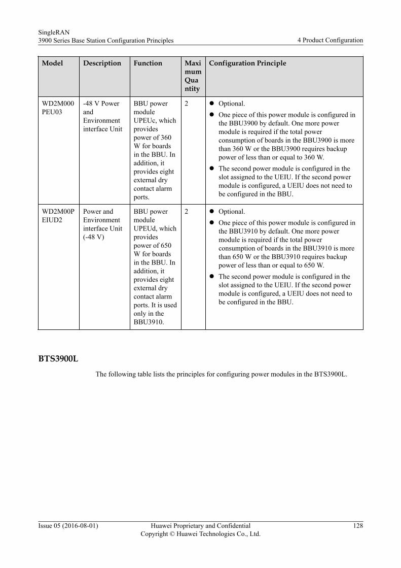
Model Description Function MaximumQuantity
Configuration Principle
WD2M000PEU03
-48 V PowerandEnvironmentinterface Unit
BBU powermoduleUPEUc, whichprovidespower of 360W for boardsin the BBU. Inaddition, itprovides eightexternal drycontact alarmports.
2 l Optional.l One piece of this power module is configured in
the BBU3900 by default. One more powermodule is required if the total powerconsumption of boards in the BBU3900 is morethan 360 W or the BBU3900 requires backuppower of less than or equal to 360 W.
l The second power module is configured in theslot assigned to the UEIU. If the second powermodule is configured, a UEIU does not need tobe configured in the BBU.
WD2M00PEIUD2
Power andEnvironmentinterface Unit(-48 V)
BBU powermoduleUPEUd, whichprovidespower of 650W for boardsin the BBU. Inaddition, itprovides eightexternal drycontact alarmports. It is usedonly in theBBU3910.
2 l Optional.l One piece of this power module is configured in
the BBU3910 by default. One more powermodule is required if the total powerconsumption of boards in the BBU3910 is morethan 650 W or the BBU3910 requires backuppower of less than or equal to 650 W.
l The second power module is configured in theslot assigned to the UEIU. If the second powermodule is configured, a UEIU does not need tobe configured in the BBU.
BTS3900LThe following table lists the principles for configuring power modules in the BTS3900L.
SingleRAN3900 Series Base Station Configuration Principles 4 Product Configuration
Issue 05 (2016-08-01) Huawei Proprietary and ConfidentialCopyright © Huawei Technologies Co., Ltd.
128
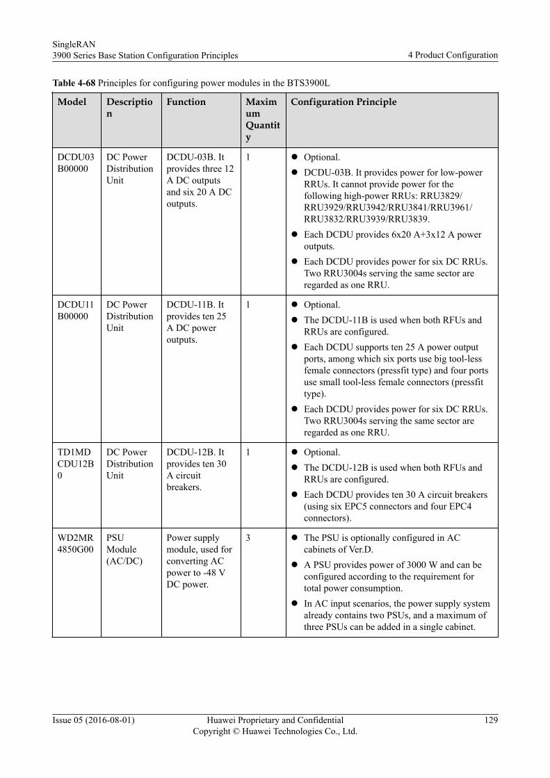
Table 4-68 Principles for configuring power modules in the BTS3900L
Model Description
Function MaximumQuantity
Configuration Principle
DCDU03B00000
DC PowerDistributionUnit
DCDU-03B. Itprovides three 12A DC outputsand six 20 A DCoutputs.
1 l Optional.l DCDU-03B. It provides power for low-power
RRUs. It cannot provide power for thefollowing high-power RRUs: RRU3829/RRU3929/RRU3942/RRU3841/RRU3961/RRU3832/RRU3939/RRU3839.
l Each DCDU provides 6x20 A+3x12 A poweroutputs.
l Each DCDU provides power for six DC RRUs.Two RRU3004s serving the same sector areregarded as one RRU.
DCDU11B00000
DC PowerDistributionUnit
DCDU-11B. Itprovides ten 25A DC poweroutputs.
1 l Optional.l The DCDU-11B is used when both RFUs and
RRUs are configured.l Each DCDU supports ten 25 A power output
ports, among which six ports use big tool-lessfemale connectors (pressfit type) and four portsuse small tool-less female connectors (pressfittype).
l Each DCDU provides power for six DC RRUs.Two RRU3004s serving the same sector areregarded as one RRU.
TD1MDCDU12B0
DC PowerDistributionUnit
DCDU-12B. Itprovides ten 30A circuitbreakers.
1 l Optional.l The DCDU-12B is used when both RFUs and
RRUs are configured.l Each DCDU provides ten 30 A circuit breakers
(using six EPC5 connectors and four EPC4connectors).
WD2MR4850G00
PSUModule(AC/DC)
Power supplymodule, used forconverting ACpower to -48 VDC power.
3 l The PSU is optionally configured in ACcabinets of Ver.D.
l A PSU provides power of 3000 W and can beconfigured according to the requirement fortotal power consumption.
l In AC input scenarios, the power supply systemalready contains two PSUs, and a maximum ofthree PSUs can be added in a single cabinet.
SingleRAN3900 Series Base Station Configuration Principles 4 Product Configuration
Issue 05 (2016-08-01) Huawei Proprietary and ConfidentialCopyright © Huawei Technologies Co., Ltd.
129
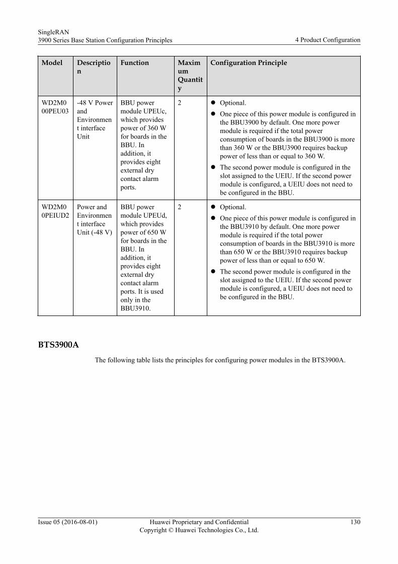
Model Description
Function MaximumQuantity
Configuration Principle
WD2M000PEU03
-48 V PowerandEnvironment interfaceUnit
BBU powermodule UPEUc,which providespower of 360 Wfor boards in theBBU. Inaddition, itprovides eightexternal drycontact alarmports.
2 l Optional.l One piece of this power module is configured in
the BBU3900 by default. One more powermodule is required if the total powerconsumption of boards in the BBU3900 is morethan 360 W or the BBU3900 requires backuppower of less than or equal to 360 W.
l The second power module is configured in theslot assigned to the UEIU. If the second powermodule is configured, a UEIU does not need tobe configured in the BBU.
WD2M00PEIUD2
Power andEnvironment interfaceUnit (-48 V)
BBU powermodule UPEUd,which providespower of 650 Wfor boards in theBBU. Inaddition, itprovides eightexternal drycontact alarmports. It is usedonly in theBBU3910.
2 l Optional.l One piece of this power module is configured in
the BBU3910 by default. One more powermodule is required if the total powerconsumption of boards in the BBU3910 is morethan 650 W or the BBU3910 requires backuppower of less than or equal to 650 W.
l The second power module is configured in theslot assigned to the UEIU. If the second powermodule is configured, a UEIU does not need tobe configured in the BBU.
BTS3900AThe following table lists the principles for configuring power modules in the BTS3900A.
SingleRAN3900 Series Base Station Configuration Principles 4 Product Configuration
Issue 05 (2016-08-01) Huawei Proprietary and ConfidentialCopyright © Huawei Technologies Co., Ltd.
130
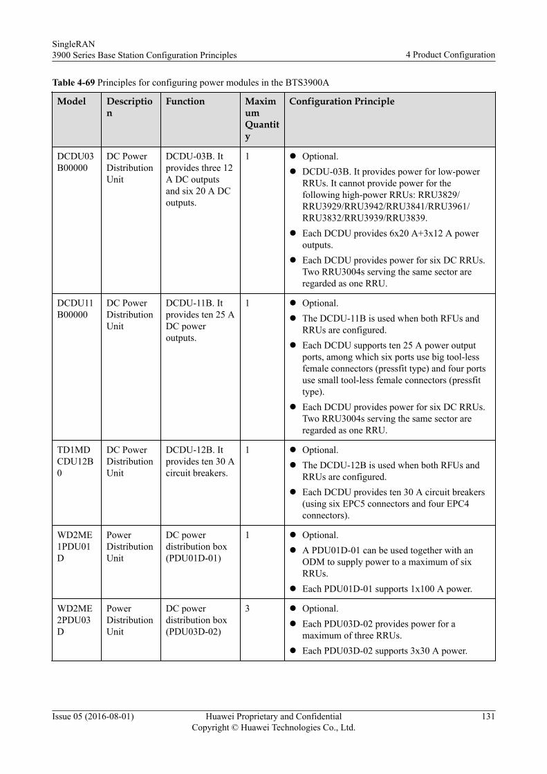
Table 4-69 Principles for configuring power modules in the BTS3900A
Model Description
Function MaximumQuantity
Configuration Principle
DCDU03B00000
DC PowerDistributionUnit
DCDU-03B. Itprovides three 12A DC outputsand six 20 A DCoutputs.
1 l Optional.l DCDU-03B. It provides power for low-power
RRUs. It cannot provide power for thefollowing high-power RRUs: RRU3829/RRU3929/RRU3942/RRU3841/RRU3961/RRU3832/RRU3939/RRU3839.
l Each DCDU provides 6x20 A+3x12 A poweroutputs.
l Each DCDU provides power for six DC RRUs.Two RRU3004s serving the same sector areregarded as one RRU.
DCDU11B00000
DC PowerDistributionUnit
DCDU-11B. Itprovides ten 25 ADC poweroutputs.
1 l Optional.l The DCDU-11B is used when both RFUs and
RRUs are configured.l Each DCDU supports ten 25 A power output
ports, among which six ports use big tool-lessfemale connectors (pressfit type) and four portsuse small tool-less female connectors (pressfittype).
l Each DCDU provides power for six DC RRUs.Two RRU3004s serving the same sector areregarded as one RRU.
TD1MDCDU12B0
DC PowerDistributionUnit
DCDU-12B. Itprovides ten 30 Acircuit breakers.
1 l Optional.l The DCDU-12B is used when both RFUs and
RRUs are configured.l Each DCDU provides ten 30 A circuit breakers
(using six EPC5 connectors and four EPC4connectors).
WD2ME1PDU01D
PowerDistributionUnit
DC powerdistribution box(PDU01D-01)
1 l Optional.l A PDU01D-01 can be used together with an
ODM to supply power to a maximum of sixRRUs.
l Each PDU01D-01 supports 1x100 A power.
WD2ME2PDU03D
PowerDistributionUnit
DC powerdistribution box(PDU03D-02)
3 l Optional.l Each PDU03D-02 provides power for a
maximum of three RRUs.l Each PDU03D-02 supports 3x30 A power.
SingleRAN3900 Series Base Station Configuration Principles 4 Product Configuration
Issue 05 (2016-08-01) Huawei Proprietary and ConfidentialCopyright © Huawei Technologies Co., Ltd.
131
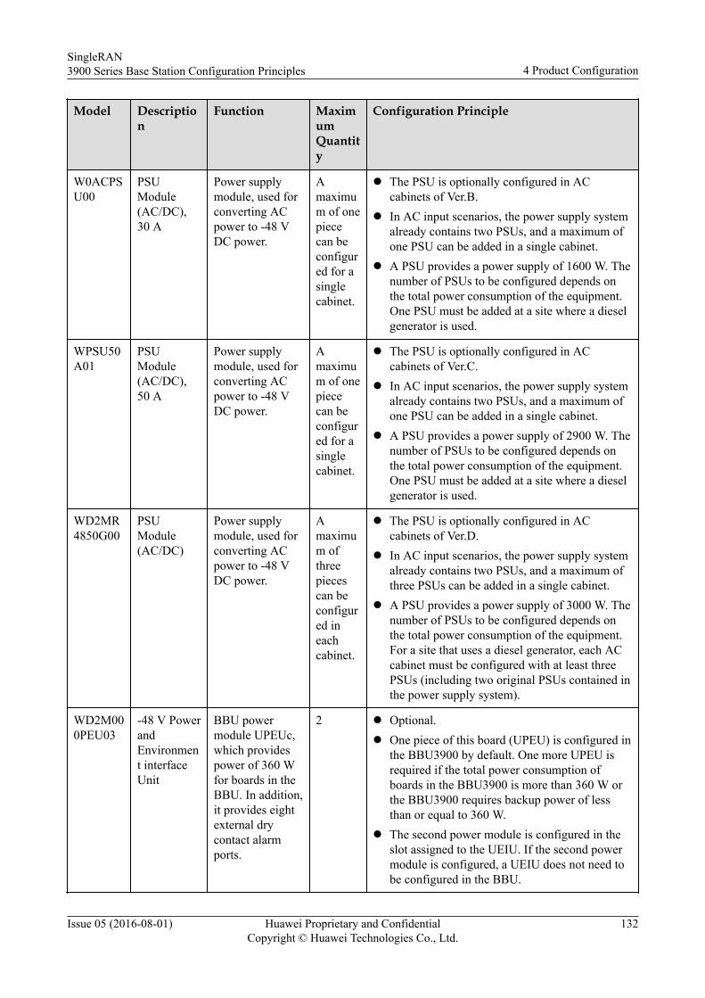
Model Description
Function MaximumQuantity
Configuration Principle
W0ACPSU00
PSUModule(AC/DC),30 A
Power supplymodule, used forconverting ACpower to -48 VDC power.
Amaximum of onepiececan beconfigured for asinglecabinet.
l The PSU is optionally configured in ACcabinets of Ver.B.
l In AC input scenarios, the power supply systemalready contains two PSUs, and a maximum ofone PSU can be added in a single cabinet.
l A PSU provides a power supply of 1600 W. Thenumber of PSUs to be configured depends onthe total power consumption of the equipment.One PSU must be added at a site where a dieselgenerator is used.
WPSU50A01
PSUModule(AC/DC),50 A
Power supplymodule, used forconverting ACpower to -48 VDC power.
Amaximum of onepiececan beconfigured for asinglecabinet.
l The PSU is optionally configured in ACcabinets of Ver.C.
l In AC input scenarios, the power supply systemalready contains two PSUs, and a maximum ofone PSU can be added in a single cabinet.
l A PSU provides a power supply of 2900 W. Thenumber of PSUs to be configured depends onthe total power consumption of the equipment.One PSU must be added at a site where a dieselgenerator is used.
WD2MR4850G00
PSUModule(AC/DC)
Power supplymodule, used forconverting ACpower to -48 VDC power.
Amaximum ofthreepiecescan beconfigured ineachcabinet.
l The PSU is optionally configured in ACcabinets of Ver.D.
l In AC input scenarios, the power supply systemalready contains two PSUs, and a maximum ofthree PSUs can be added in a single cabinet.
l A PSU provides a power supply of 3000 W. Thenumber of PSUs to be configured depends onthe total power consumption of the equipment.For a site that uses a diesel generator, each ACcabinet must be configured with at least threePSUs (including two original PSUs contained inthe power supply system).
WD2M000PEU03
-48 V PowerandEnvironment interfaceUnit
BBU powermodule UPEUc,which providespower of 360 Wfor boards in theBBU. In addition,it provides eightexternal drycontact alarmports.
2 l Optional.l One piece of this board (UPEU) is configured in
the BBU3900 by default. One more UPEU isrequired if the total power consumption ofboards in the BBU3900 is more than 360 W orthe BBU3900 requires backup power of lessthan or equal to 360 W.
l The second power module is configured in theslot assigned to the UEIU. If the second powermodule is configured, a UEIU does not need tobe configured in the BBU.
SingleRAN3900 Series Base Station Configuration Principles 4 Product Configuration
Issue 05 (2016-08-01) Huawei Proprietary and ConfidentialCopyright © Huawei Technologies Co., Ltd.
132
Model Description
Function MaximumQuantity
Configuration Principle
WD2M00PEIUD2
Power andEnvironment interfaceUnit (-48 V)
BBU powermodule UPEUd,which providespower of 650 Wfor boards in theBBU. In addition,it provides eightexternal drycontact alarmports. It is usedonly in theBBU3910.
2 l Optional.l One piece of this power module is configured in
the BBU3910 by default. One more powermodule is required if the total powerconsumption of boards in the BBU3910 is morethan 650 W or the BBU3910 requires backuppower of less than or equal to 650 W.
l The second power module is configured in theslot assigned to the UEIU. If the second powermodule is configured, a UEIU does not need tobe configured in the BBU.
BTS3900ALThe following table lists the principles for configuring power modules in the BTS3900AL.
Table 4-70 Principles for configuring power modules in the BTS3900AL
Model Description
Function MaximumQuantity
Configuration Principle
WD2P000PEU00
Power andEnvironment interfaceUnit (-48 V)
BBU powermodule UPEUc,which providespower of 360 Wfor boards in theBBU. Inaddition, itprovides eightexternal drycontact alarmports.
2 l Optional.l One piece of this power module is configured in
the BBU3900 by default. One more powermodule is required if the total powerconsumption of boards in the BBU3900 is morethan 360 W or the BBU3900 requires backuppower of less than or equal to 360 W.
l The second power module is configured in theslot assigned to the UEIU. If the second powermodule is configured, a UEIU does not need tobe configured in the BBU.
SingleRAN3900 Series Base Station Configuration Principles 4 Product Configuration
Issue 05 (2016-08-01) Huawei Proprietary and ConfidentialCopyright © Huawei Technologies Co., Ltd.
133
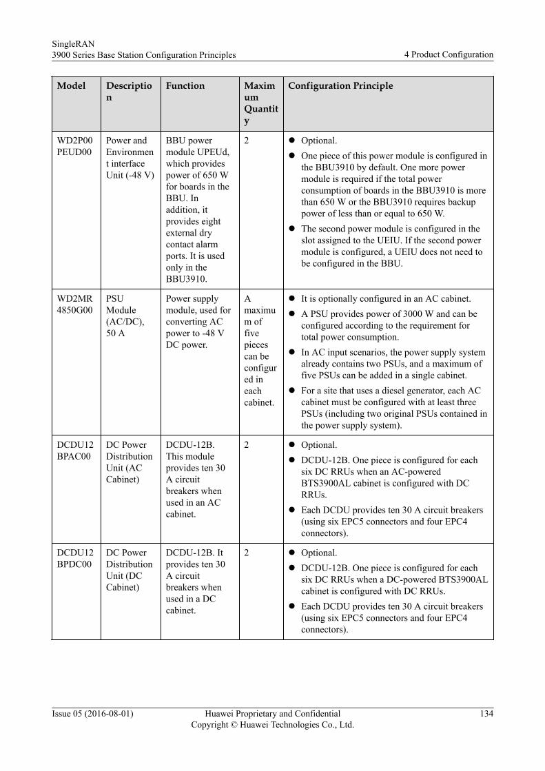
Model Description
Function MaximumQuantity
Configuration Principle
WD2P00PEUD00
Power andEnvironment interfaceUnit (-48 V)
BBU powermodule UPEUd,which providespower of 650 Wfor boards in theBBU. Inaddition, itprovides eightexternal drycontact alarmports. It is usedonly in theBBU3910.
2 l Optional.l One piece of this power module is configured in
the BBU3910 by default. One more powermodule is required if the total powerconsumption of boards in the BBU3910 is morethan 650 W or the BBU3910 requires backuppower of less than or equal to 650 W.
l The second power module is configured in theslot assigned to the UEIU. If the second powermodule is configured, a UEIU does not need tobe configured in the BBU.
WD2MR4850G00
PSUModule(AC/DC),50 A
Power supplymodule, used forconverting ACpower to -48 VDC power.
Amaximum offivepiecescan beconfigured ineachcabinet.
l It is optionally configured in an AC cabinet.l A PSU provides power of 3000 W and can be
configured according to the requirement fortotal power consumption.
l In AC input scenarios, the power supply systemalready contains two PSUs, and a maximum offive PSUs can be added in a single cabinet.
l For a site that uses a diesel generator, each ACcabinet must be configured with at least threePSUs (including two original PSUs contained inthe power supply system).
DCDU12BPAC00
DC PowerDistributionUnit (ACCabinet)
DCDU-12B.This moduleprovides ten 30A circuitbreakers whenused in an ACcabinet.
2 l Optional.l DCDU-12B. One piece is configured for each
six DC RRUs when an AC-poweredBTS3900AL cabinet is configured with DCRRUs.
l Each DCDU provides ten 30 A circuit breakers(using six EPC5 connectors and four EPC4connectors).
DCDU12BPDC00
DC PowerDistributionUnit (DCCabinet)
DCDU-12B. Itprovides ten 30A circuitbreakers whenused in a DCcabinet.
2 l Optional.l DCDU-12B. One piece is configured for each
six DC RRUs when a DC-powered BTS3900ALcabinet is configured with DC RRUs.
l Each DCDU provides ten 30 A circuit breakers(using six EPC5 connectors and four EPC4connectors).
SingleRAN3900 Series Base Station Configuration Principles 4 Product Configuration
Issue 05 (2016-08-01) Huawei Proprietary and ConfidentialCopyright © Huawei Technologies Co., Ltd.
134
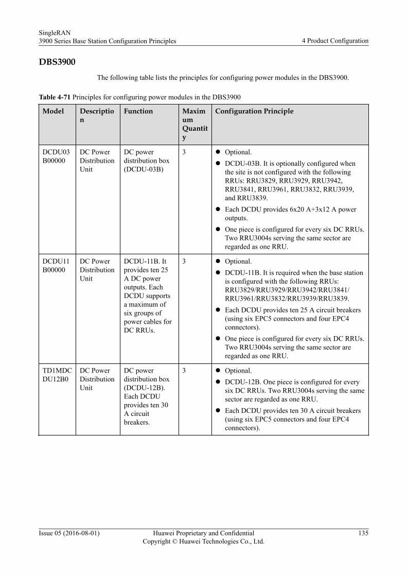
DBS3900The following table lists the principles for configuring power modules in the DBS3900.
Table 4-71 Principles for configuring power modules in the DBS3900
Model Description
Function MaximumQuantity
Configuration Principle
DCDU03B00000
DC PowerDistributionUnit
DC powerdistribution box(DCDU-03B)
3 l Optional.l DCDU-03B. It is optionally configured when
the site is not configured with the followingRRUs: RRU3829, RRU3929, RRU3942,RRU3841, RRU3961, RRU3832, RRU3939,and RRU3839.
l Each DCDU provides 6x20 A+3x12 A poweroutputs.
l One piece is configured for every six DC RRUs.Two RRU3004s serving the same sector areregarded as one RRU.
DCDU11B00000
DC PowerDistributionUnit
DCDU-11B. Itprovides ten 25A DC poweroutputs. EachDCDU supportsa maximum ofsix groups ofpower cables forDC RRUs.
3 l Optional.l DCDU-11B. It is required when the base station
is configured with the following RRUs:RRU3829/RRU3929/RRU3942/RRU3841/RRU3961/RRU3832/RRU3939/RRU3839.
l Each DCDU provides ten 25 A circuit breakers(using six EPC5 connectors and four EPC4connectors).
l One piece is configured for every six DC RRUs.Two RRU3004s serving the same sector areregarded as one RRU.
TD1MDCDU12B0
DC PowerDistributionUnit
DC powerdistribution box(DCDU-12B).Each DCDUprovides ten 30A circuitbreakers.
3 l Optional.l DCDU-12B. One piece is configured for every
six DC RRUs. Two RRU3004s serving the samesector are regarded as one RRU.
l Each DCDU provides ten 30 A circuit breakers(using six EPC5 connectors and four EPC4connectors).
SingleRAN3900 Series Base Station Configuration Principles 4 Product Configuration
Issue 05 (2016-08-01) Huawei Proprietary and ConfidentialCopyright © Huawei Technologies Co., Ltd.
135
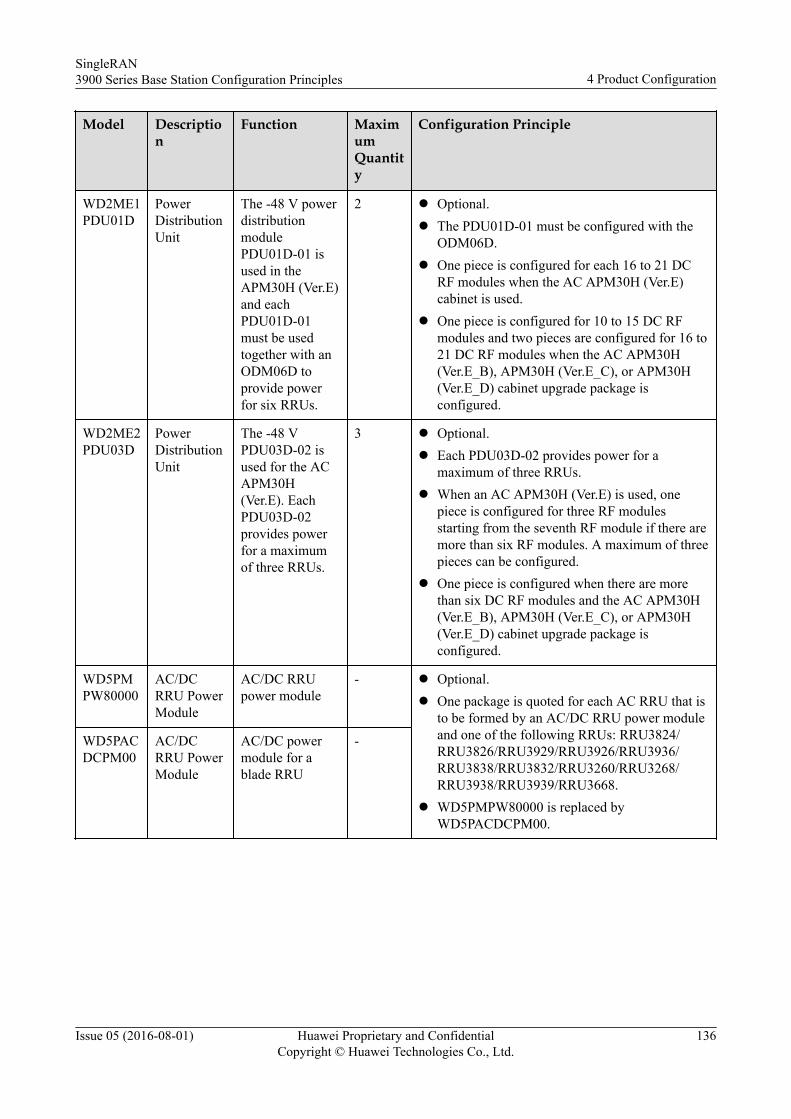
Model Description
Function MaximumQuantity
Configuration Principle
WD2ME1PDU01D
PowerDistributionUnit
The -48 V powerdistributionmodulePDU01D-01 isused in theAPM30H (Ver.E)and eachPDU01D-01must be usedtogether with anODM06D toprovide powerfor six RRUs.
2 l Optional.l The PDU01D-01 must be configured with the
ODM06D.l One piece is configured for each 16 to 21 DC
RF modules when the AC APM30H (Ver.E)cabinet is used.
l One piece is configured for 10 to 15 DC RFmodules and two pieces are configured for 16 to21 DC RF modules when the AC APM30H(Ver.E_B), APM30H (Ver.E_C), or APM30H(Ver.E_D) cabinet upgrade package isconfigured.
WD2ME2PDU03D
PowerDistributionUnit
The -48 VPDU03D-02 isused for the ACAPM30H(Ver.E). EachPDU03D-02provides powerfor a maximumof three RRUs.
3 l Optional.l Each PDU03D-02 provides power for a
maximum of three RRUs.l When an AC APM30H (Ver.E) is used, one
piece is configured for three RF modulesstarting from the seventh RF module if there aremore than six RF modules. A maximum of threepieces can be configured.
l One piece is configured when there are morethan six DC RF modules and the AC APM30H(Ver.E_B), APM30H (Ver.E_C), or APM30H(Ver.E_D) cabinet upgrade package isconfigured.
WD5PMPW80000
AC/DCRRU PowerModule
AC/DC RRUpower module
- l Optional.l One package is quoted for each AC RRU that is
to be formed by an AC/DC RRU power moduleand one of the following RRUs: RRU3824/RRU3826/RRU3929/RRU3926/RRU3936/RRU3838/RRU3832/RRU3260/RRU3268/RRU3938/RRU3939/RRU3668.
l WD5PMPW80000 is replaced byWD5PACDCPM00.
WD5PACDCPM00
AC/DCRRU PowerModule
AC/DC powermodule for ablade RRU
-
SingleRAN3900 Series Base Station Configuration Principles 4 Product Configuration
Issue 05 (2016-08-01) Huawei Proprietary and ConfidentialCopyright © Huawei Technologies Co., Ltd.
136
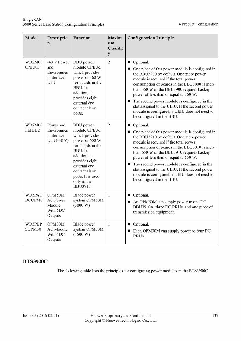
Model Description
Function MaximumQuantity
Configuration Principle
WD2M000PEU03
-48 V PowerandEnvironment interfaceUnit
BBU powermodule UPEUc,which providespower of 360 Wfor boards in theBBU. Inaddition, itprovides eightexternal drycontact alarmports.
2 l Optional.l One piece of this power module is configured in
the BBU3900 by default. One more powermodule is required if the total powerconsumption of boards in the BBU3900 is morethan 360 W or the BBU3900 requires backuppower of less than or equal to 360 W.
l The second power module is configured in theslot assigned to the UEIU. If the second powermodule is configured, a UEIU does not need tobe configured in the BBU.
WD2M00PEIUD2
Power andEnvironment interfaceUnit (-48 V)
BBU powermodule UPEUd,which providespower of 650 Wfor boards in theBBU. Inaddition, itprovides eightexternal drycontact alarmports. It is usedonly in theBBU3910.
2 l Optional.l One piece of this power module is configured in
the BBU3910 by default. One more powermodule is required if the total powerconsumption of boards in the BBU3910 is morethan 650 W or the BBU3910 requires backuppower of less than or equal to 650 W.
l The second power module is configured in theslot assigned to the UEIU. If the second powermodule is configured, a UEIU does not need tobe configured in the BBU.
WD5PACDCOPM0
OPM50MAC PowerModuleWith 6DCOutputs
Blade powersystem OPM50M(3000 W)
1 l Optional.l An OPM50M can supply power to one DC
BBU3910A, three DC RRUs, and one piece oftransmission equipment.
WD5PBPSOPM30
OPM30MAC ModuleWith 4DCOutputs
Blade powersystem OPM30M(1500 W)
1 l Optional.l Each OPM30M can supply power to four DC
RRUs.
BTS3900CThe following table lists the principles for configuring power modules in the BTS3900C.
SingleRAN3900 Series Base Station Configuration Principles 4 Product Configuration
Issue 05 (2016-08-01) Huawei Proprietary and ConfidentialCopyright © Huawei Technologies Co., Ltd.
137
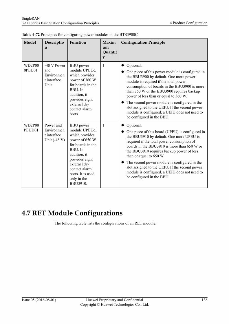
Table 4-72 Principles for configuring power modules in the BTS3900C
Model Description
Function MaximumQuantity
Configuration Principle
WD2P000PEU01
-48 V PowerandEnvironment interfaceUnit
BBU powermodule UPEUc,which providespower of 360 Wfor boards in theBBU. Inaddition, itprovides eightexternal drycontact alarmports.
1 l Optional.l One piece of this power module is configured in
the BBU3900 by default. One more powermodule is required if the total powerconsumption of boards in the BBU3900 is morethan 360 W or the BBU3900 requires backuppower of less than or equal to 360 W.
l The second power module is configured in theslot assigned to the UEIU. If the second powermodule is configured, a UEIU does not need tobe configured in the BBU.
WD2P00PEUD01
Power andEnvironment interfaceUnit (-48 V)
BBU powermodule UPEUd,which providespower of 650 Wfor boards in theBBU. Inaddition, itprovides eightexternal drycontact alarmports. It is usedonly in theBBU3910.
1 l Optional.l One piece of this board (UPEU) is configured in
the BBU3910 by default. One more UPEU isrequired if the total power consumption ofboards in the BBU3910 is more than 650 W orthe BBU3910 requires backup power of lessthan or equal to 650 W.
l The second power module is configured in theslot assigned to the UEIU. If the second powermodule is configured, a UEIU does not need tobe configured in the BBU.
4.7 RET Module ConfigurationsThe following table lists the configurations of an RET module.
SingleRAN3900 Series Base Station Configuration Principles 4 Product Configuration
Issue 05 (2016-08-01) Huawei Proprietary and ConfidentialCopyright © Huawei Technologies Co., Ltd.
138
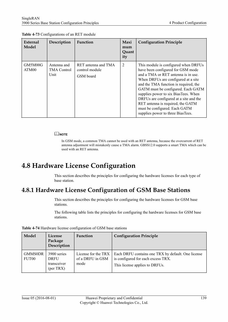
Table 4-73 Configurations of an RET module
ExternalModel
Description Function MaximumQuantity
Configuration Principle
GM5M00GATM00
Antenna andTMA ControlUnit
RET antenna and TMAcontrol moduleGSM board
2 This module is configured when DRFUshave been configured for GSM modeand a TMA or RET antenna is in use.When DRFUs are configured at a siteand the TMA function is required, theGATM must be configured. Each GATMsupplies power to six BiasTees. WhenDRFUs are configured at a site and theRET antenna is required, the GATMmust be configured. Each GATMsupplies power to three BiasTees.
NOTE
In GSM mode, a common TMA cannot be used with an RET antenna, because the overcurrent of RETantenna adjustment will mistakenly cause a TMA alarm. GBSS12.0 supports a smart TMA which can beused with an RET antenna.
4.8 Hardware License ConfigurationThis section describes the principles for configuring the hardware licenses for each type ofbase station.
4.8.1 Hardware License Configuration of GSM Base StationsThis section describes the principles for configuring the hardware licenses for GSM basestations.
The following table lists the principles for configuring the hardware licenses for GSM basestations.
Table 4-74 Hardware license configuration of GSM base stations
Model LicensePackageDescription
Function Configuration Principle
GMMS0DRFUT00
3900 seriesDRFUtransceiver(per TRX)
License for the TRXof a DRFU in GSMmode
Each DRFU contains one TRX by default. One licenseis configured for each excess TRX.This license applies to DRFUs.
SingleRAN3900 Series Base Station Configuration Principles 4 Product Configuration
Issue 05 (2016-08-01) Huawei Proprietary and ConfidentialCopyright © Huawei Technologies Co., Ltd.
139
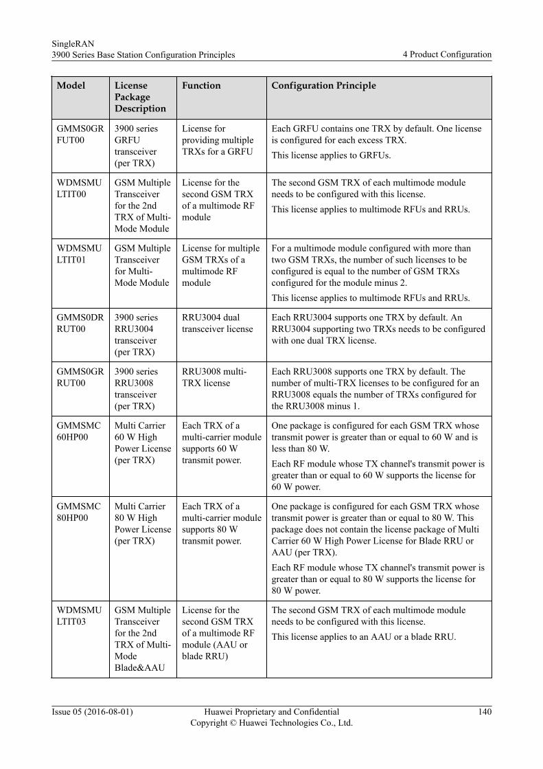
Model LicensePackageDescription
Function Configuration Principle
GMMS0GRFUT00
3900 seriesGRFUtransceiver(per TRX)
License forproviding multipleTRXs for a GRFU
Each GRFU contains one TRX by default. One licenseis configured for each excess TRX.This license applies to GRFUs.
WDMSMULTIT00
GSM MultipleTransceiverfor the 2ndTRX of Multi-Mode Module
License for thesecond GSM TRXof a multimode RFmodule
The second GSM TRX of each multimode moduleneeds to be configured with this license.This license applies to multimode RFUs and RRUs.
WDMSMULTIT01
GSM MultipleTransceiverfor Multi-Mode Module
License for multipleGSM TRXs of amultimode RFmodule
For a multimode module configured with more thantwo GSM TRXs, the number of such licenses to beconfigured is equal to the number of GSM TRXsconfigured for the module minus 2.This license applies to multimode RFUs and RRUs.
GMMS0DRRUT00
3900 seriesRRU3004transceiver(per TRX)
RRU3004 dualtransceiver license
Each RRU3004 supports one TRX by default. AnRRU3004 supporting two TRXs needs to be configuredwith one dual TRX license.
GMMS0GRRUT00
3900 seriesRRU3008transceiver(per TRX)
RRU3008 multi-TRX license
Each RRU3008 supports one TRX by default. Thenumber of multi-TRX licenses to be configured for anRRU3008 equals the number of TRXs configured forthe RRU3008 minus 1.
GMMSMC60HP00
Multi Carrier60 W HighPower License(per TRX)
Each TRX of amulti-carrier modulesupports 60 Wtransmit power.
One package is configured for each GSM TRX whosetransmit power is greater than or equal to 60 W and isless than 80 W.Each RF module whose TX channel's transmit power isgreater than or equal to 60 W supports the license for60 W power.
GMMSMC80HP00
Multi Carrier80 W HighPower License(per TRX)
Each TRX of amulti-carrier modulesupports 80 Wtransmit power.
One package is configured for each GSM TRX whosetransmit power is greater than or equal to 80 W. Thispackage does not contain the license package of MultiCarrier 60 W High Power License for Blade RRU orAAU (per TRX).Each RF module whose TX channel's transmit power isgreater than or equal to 80 W supports the license for80 W power.
WDMSMULTIT03
GSM MultipleTransceiverfor the 2ndTRX of Multi-ModeBlade&AAU
License for thesecond GSM TRXof a multimode RFmodule (AAU orblade RRU)
The second GSM TRX of each multimode moduleneeds to be configured with this license.This license applies to an AAU or a blade RRU.
SingleRAN3900 Series Base Station Configuration Principles 4 Product Configuration
Issue 05 (2016-08-01) Huawei Proprietary and ConfidentialCopyright © Huawei Technologies Co., Ltd.
140
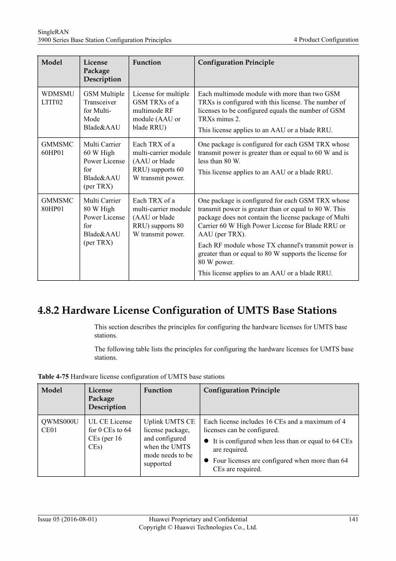
Model LicensePackageDescription
Function Configuration Principle
WDMSMULTIT02
GSM MultipleTransceiverfor Multi-ModeBlade&AAU
License for multipleGSM TRXs of amultimode RFmodule (AAU orblade RRU)
Each multimode module with more than two GSMTRXs is configured with this license. The number oflicenses to be configured equals the number of GSMTRXs minus 2.This license applies to an AAU or a blade RRU.
GMMSMC60HP01
Multi Carrier60 W HighPower LicenseforBlade&AAU(per TRX)
Each TRX of amulti-carrier module(AAU or bladeRRU) supports 60W transmit power.
One package is configured for each GSM TRX whosetransmit power is greater than or equal to 60 W and isless than 80 W.This license applies to an AAU or a blade RRU.
GMMSMC80HP01
Multi Carrier80 W HighPower LicenseforBlade&AAU(per TRX)
Each TRX of amulti-carrier module(AAU or bladeRRU) supports 80W transmit power.
One package is configured for each GSM TRX whosetransmit power is greater than or equal to 80 W. Thispackage does not contain the license package of MultiCarrier 60 W High Power License for Blade RRU orAAU (per TRX).Each RF module whose TX channel's transmit power isgreater than or equal to 80 W supports the license for80 W power.This license applies to an AAU or a blade RRU.
4.8.2 Hardware License Configuration of UMTS Base StationsThis section describes the principles for configuring the hardware licenses for UMTS basestations.
The following table lists the principles for configuring the hardware licenses for UMTS basestations.
Table 4-75 Hardware license configuration of UMTS base stations
Model LicensePackageDescription
Function Configuration Principle
QWMS000UCE01
UL CE Licensefor 0 CEs to 64CEs (per 16CEs)
Uplink UMTS CElicense package,and configuredwhen the UMTSmode needs to besupported
Each license includes 16 CEs and a maximum of 4licenses can be configured.l It is configured when less than or equal to 64 CEs
are required.l Four licenses are configured when more than 64
CEs are required.
SingleRAN3900 Series Base Station Configuration Principles 4 Product Configuration
Issue 05 (2016-08-01) Huawei Proprietary and ConfidentialCopyright © Huawei Technologies Co., Ltd.
141
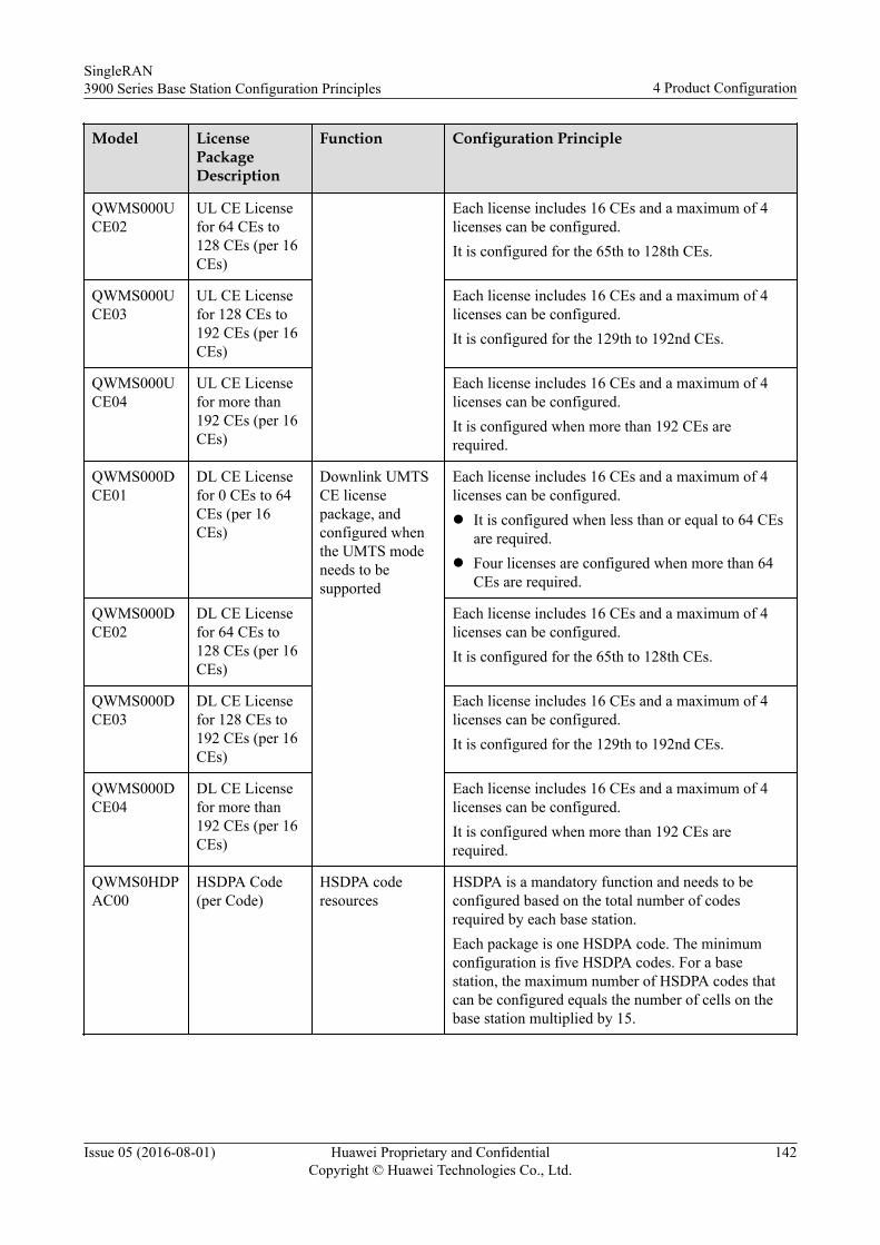
Model LicensePackageDescription
Function Configuration Principle
QWMS000UCE02
UL CE Licensefor 64 CEs to128 CEs (per 16CEs)
Each license includes 16 CEs and a maximum of 4licenses can be configured.It is configured for the 65th to 128th CEs.
QWMS000UCE03
UL CE Licensefor 128 CEs to192 CEs (per 16CEs)
Each license includes 16 CEs and a maximum of 4licenses can be configured.It is configured for the 129th to 192nd CEs.
QWMS000UCE04
UL CE Licensefor more than192 CEs (per 16CEs)
Each license includes 16 CEs and a maximum of 4licenses can be configured.It is configured when more than 192 CEs arerequired.
QWMS000DCE01
DL CE Licensefor 0 CEs to 64CEs (per 16CEs)
Downlink UMTSCE licensepackage, andconfigured whenthe UMTS modeneeds to besupported
Each license includes 16 CEs and a maximum of 4licenses can be configured.l It is configured when less than or equal to 64 CEs
are required.l Four licenses are configured when more than 64
CEs are required.
QWMS000DCE02
DL CE Licensefor 64 CEs to128 CEs (per 16CEs)
Each license includes 16 CEs and a maximum of 4licenses can be configured.It is configured for the 65th to 128th CEs.
QWMS000DCE03
DL CE Licensefor 128 CEs to192 CEs (per 16CEs)
Each license includes 16 CEs and a maximum of 4licenses can be configured.It is configured for the 129th to 192nd CEs.
QWMS000DCE04
DL CE Licensefor more than192 CEs (per 16CEs)
Each license includes 16 CEs and a maximum of 4licenses can be configured.It is configured when more than 192 CEs arerequired.
QWMS0HDPAC00
HSDPA Code(per Code)
HSDPA coderesources
HSDPA is a mandatory function and needs to beconfigured based on the total number of codesrequired by each base station.Each package is one HSDPA code. The minimumconfiguration is five HSDPA codes. For a basestation, the maximum number of HSDPA codes thatcan be configured equals the number of cells on thebase station multiplied by 15.
SingleRAN3900 Series Base Station Configuration Principles 4 Product Configuration
Issue 05 (2016-08-01) Huawei Proprietary and ConfidentialCopyright © Huawei Technologies Co., Ltd.
142
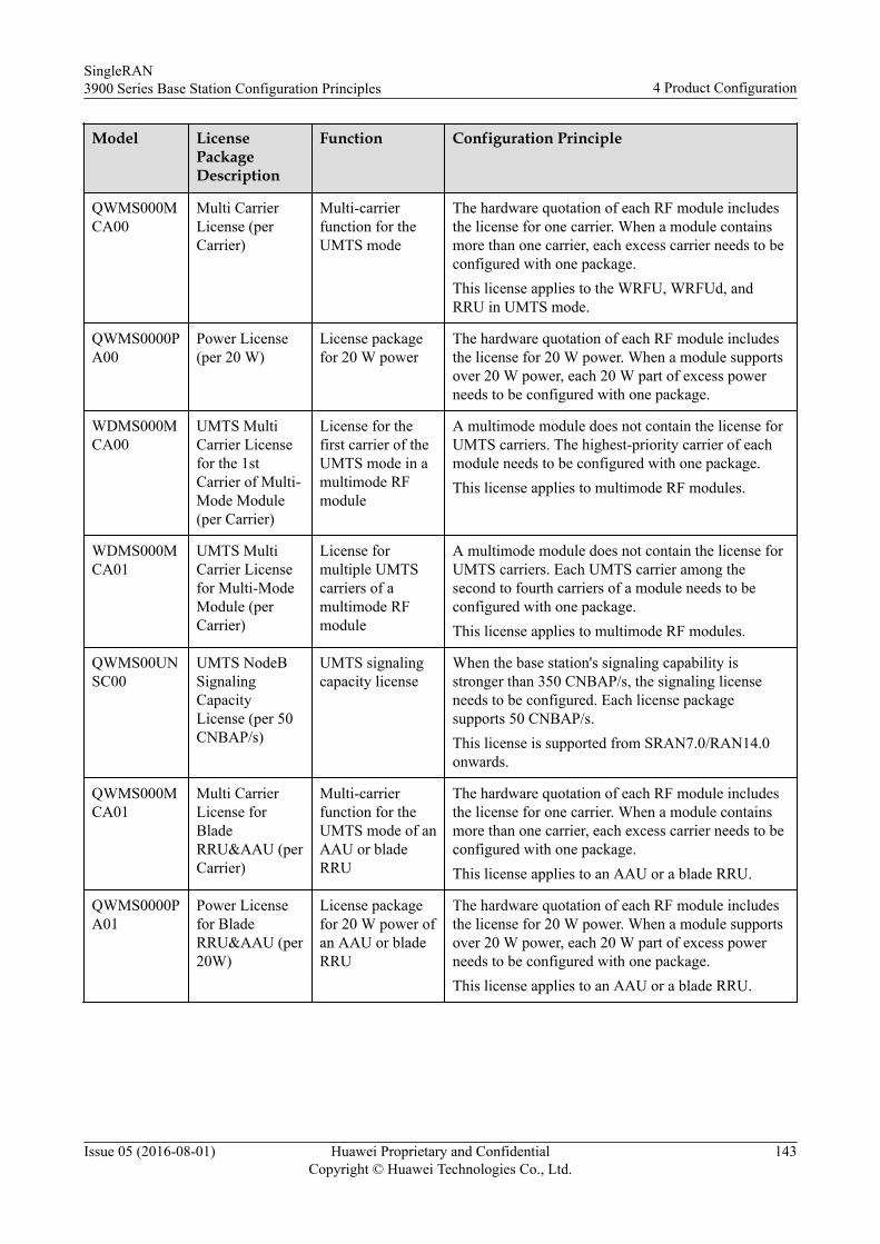
Model LicensePackageDescription
Function Configuration Principle
QWMS000MCA00
Multi CarrierLicense (perCarrier)
Multi-carrierfunction for theUMTS mode
The hardware quotation of each RF module includesthe license for one carrier. When a module containsmore than one carrier, each excess carrier needs to beconfigured with one package.This license applies to the WRFU, WRFUd, andRRU in UMTS mode.
QWMS0000PA00
Power License(per 20 W)
License packagefor 20 W power
The hardware quotation of each RF module includesthe license for 20 W power. When a module supportsover 20 W power, each 20 W part of excess powerneeds to be configured with one package.
WDMS000MCA00
UMTS MultiCarrier Licensefor the 1stCarrier of Multi-Mode Module(per Carrier)
License for thefirst carrier of theUMTS mode in amultimode RFmodule
A multimode module does not contain the license forUMTS carriers. The highest-priority carrier of eachmodule needs to be configured with one package.This license applies to multimode RF modules.
WDMS000MCA01
UMTS MultiCarrier Licensefor Multi-ModeModule (perCarrier)
License formultiple UMTScarriers of amultimode RFmodule
A multimode module does not contain the license forUMTS carriers. Each UMTS carrier among thesecond to fourth carriers of a module needs to beconfigured with one package.This license applies to multimode RF modules.
QWMS00UNSC00
UMTS NodeBSignalingCapacityLicense (per 50CNBAP/s)
UMTS signalingcapacity license
When the base station's signaling capability isstronger than 350 CNBAP/s, the signaling licenseneeds to be configured. Each license packagesupports 50 CNBAP/s.This license is supported from SRAN7.0/RAN14.0onwards.
QWMS000MCA01
Multi CarrierLicense forBladeRRU&AAU (perCarrier)
Multi-carrierfunction for theUMTS mode of anAAU or bladeRRU
The hardware quotation of each RF module includesthe license for one carrier. When a module containsmore than one carrier, each excess carrier needs to beconfigured with one package.This license applies to an AAU or a blade RRU.
QWMS0000PA01
Power Licensefor BladeRRU&AAU (per20W)
License packagefor 20 W power ofan AAU or bladeRRU
The hardware quotation of each RF module includesthe license for 20 W power. When a module supportsover 20 W power, each 20 W part of excess powerneeds to be configured with one package.This license applies to an AAU or a blade RRU.
SingleRAN3900 Series Base Station Configuration Principles 4 Product Configuration
Issue 05 (2016-08-01) Huawei Proprietary and ConfidentialCopyright © Huawei Technologies Co., Ltd.
143
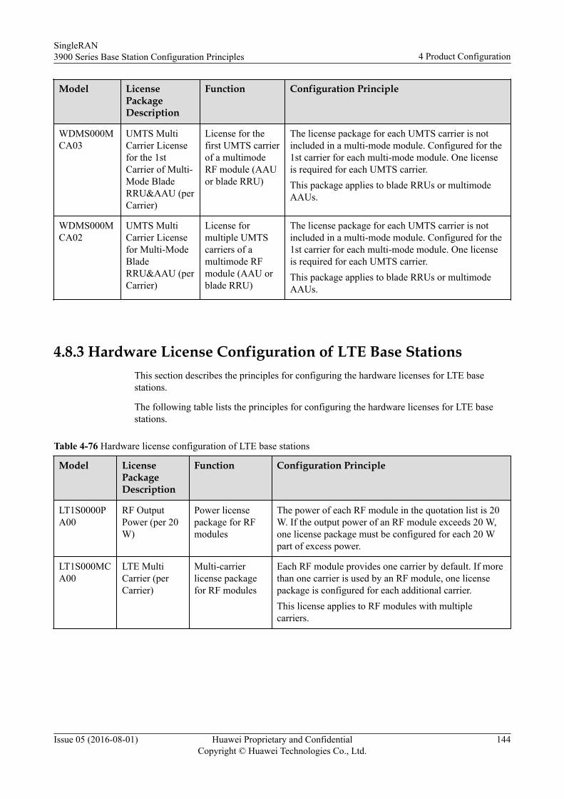
Model LicensePackageDescription
Function Configuration Principle
WDMS000MCA03
UMTS MultiCarrier Licensefor the 1stCarrier of Multi-Mode BladeRRU&AAU (perCarrier)
License for thefirst UMTS carrierof a multimodeRF module (AAUor blade RRU)
The license package for each UMTS carrier is notincluded in a multi-mode module. Configured for the1st carrier for each multi-mode module. One licenseis required for each UMTS carrier.This package applies to blade RRUs or multimodeAAUs.
WDMS000MCA02
UMTS MultiCarrier Licensefor Multi-ModeBladeRRU&AAU (perCarrier)
License formultiple UMTScarriers of amultimode RFmodule (AAU orblade RRU)
The license package for each UMTS carrier is notincluded in a multi-mode module. Configured for the1st carrier for each multi-mode module. One licenseis required for each UMTS carrier.This package applies to blade RRUs or multimodeAAUs.
4.8.3 Hardware License Configuration of LTE Base StationsThis section describes the principles for configuring the hardware licenses for LTE basestations.
The following table lists the principles for configuring the hardware licenses for LTE basestations.
Table 4-76 Hardware license configuration of LTE base stations
Model LicensePackageDescription
Function Configuration Principle
LT1S0000PA00
RF OutputPower (per 20W)
Power licensepackage for RFmodules
The power of each RF module in the quotation list is 20W. If the output power of an RF module exceeds 20 W,one license package must be configured for each 20 Wpart of excess power.
LT1S000MCA00
LTE MultiCarrier (perCarrier)
Multi-carrierlicense packagefor RF modules
Each RF module provides one carrier by default. If morethan one carrier is used by an RF module, one licensepackage is configured for each additional carrier.This license applies to RF modules with multiplecarriers.
SingleRAN3900 Series Base Station Configuration Principles 4 Product Configuration
Issue 05 (2016-08-01) Huawei Proprietary and ConfidentialCopyright © Huawei Technologies Co., Ltd.
144
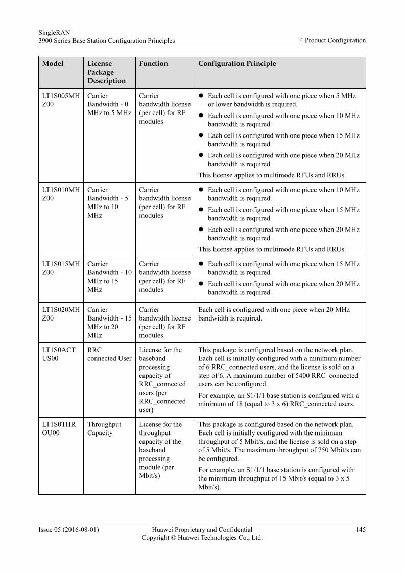
Model LicensePackageDescription
Function Configuration Principle
LT1S005MHZ00
CarrierBandwidth - 0MHz to 5 MHz
Carrierbandwidth license(per cell) for RFmodules
l Each cell is configured with one piece when 5 MHzor lower bandwidth is required.
l Each cell is configured with one piece when 10 MHzbandwidth is required.
l Each cell is configured with one piece when 15 MHzbandwidth is required.
l Each cell is configured with one piece when 20 MHzbandwidth is required.
This license applies to multimode RFUs and RRUs.
LT1S010MHZ00
CarrierBandwidth - 5MHz to 10MHz
Carrierbandwidth license(per cell) for RFmodules
l Each cell is configured with one piece when 10 MHzbandwidth is required.
l Each cell is configured with one piece when 15 MHzbandwidth is required.
l Each cell is configured with one piece when 20 MHzbandwidth is required.
This license applies to multimode RFUs and RRUs.
LT1S015MHZ00
CarrierBandwidth - 10MHz to 15MHz
Carrierbandwidth license(per cell) for RFmodules
l Each cell is configured with one piece when 15 MHzbandwidth is required.
l Each cell is configured with one piece when 20 MHzbandwidth is required.
LT1S020MHZ00
CarrierBandwidth - 15MHz to 20MHz
Carrierbandwidth license(per cell) for RFmodules
Each cell is configured with one piece when 20 MHzbandwidth is required.
LT1S0ACTUS00
RRCconnected User
License for thebasebandprocessingcapacity ofRRC_connectedusers (perRRC_connecteduser)
This package is configured based on the network plan.Each cell is initially configured with a minimum numberof 6 RRC_connected users, and the license is sold on astep of 6. A maximum number of 5400 RRC_connectedusers can be configured.For example, an S1/1/1 base station is configured with aminimum of 18 (equal to 3 x 6) RRC_connected users.
LT1S0THROU00
ThroughputCapacity
License for thethroughputcapacity of thebasebandprocessingmodule (perMbit/s)
This package is configured based on the network plan.Each cell is initially configured with the minimumthroughput of 5 Mbit/s, and the license is sold on a stepof 5 Mbit/s. The maximum throughput of 750 Mbit/s canbe configured.For example, an S1/1/1 base station is configured withthe minimum throughput of 15 Mbit/s (equal to 3 x 5Mbit/s).
SingleRAN3900 Series Base Station Configuration Principles 4 Product Configuration
Issue 05 (2016-08-01) Huawei Proprietary and ConfidentialCopyright © Huawei Technologies Co., Ltd.
145
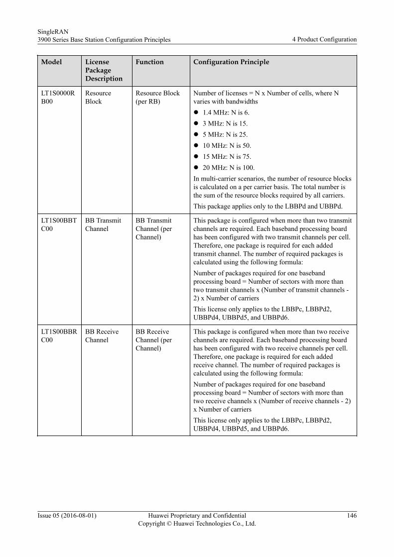
Model LicensePackageDescription
Function Configuration Principle
LT1S0000RB00
ResourceBlock
Resource Block(per RB)
Number of licenses = N x Number of cells, where Nvaries with bandwidthsl 1.4 MHz: N is 6.l 3 MHz: N is 15.l 5 MHz: N is 25.l 10 MHz: N is 50.l 15 MHz: N is 75.l 20 MHz: N is 100.In multi-carrier scenarios, the number of resource blocksis calculated on a per carrier basis. The total number isthe sum of the resource blocks required by all carriers.This package applies only to the LBBPd and UBBPd.
LT1S00BBTC00
BB TransmitChannel
BB TransmitChannel (perChannel)
This package is configured when more than two transmitchannels are required. Each baseband processing boardhas been configured with two transmit channels per cell.Therefore, one package is required for each addedtransmit channel. The number of required packages iscalculated using the following formula:Number of packages required for one basebandprocessing board = Number of sectors with more thantwo transmit channels x (Number of transmit channels -2) x Number of carriersThis license only applies to the LBBPc, LBBPd2,UBBPd4, UBBPd5, and UBBPd6.
LT1S00BBRC00
BB ReceiveChannel
BB ReceiveChannel (perChannel)
This package is configured when more than two receivechannels are required. Each baseband processing boardhas been configured with two receive channels per cell.Therefore, one package is required for each addedreceive channel. The number of required packages iscalculated using the following formula:Number of packages required for one basebandprocessing board = Number of sectors with more thantwo receive channels x (Number of receive channels - 2)x Number of carriersThis license only applies to the LBBPc, LBBPd2,UBBPd4, UBBPd5, and UBBPd6.
SingleRAN3900 Series Base Station Configuration Principles 4 Product Configuration
Issue 05 (2016-08-01) Huawei Proprietary and ConfidentialCopyright © Huawei Technologies Co., Ltd.
146
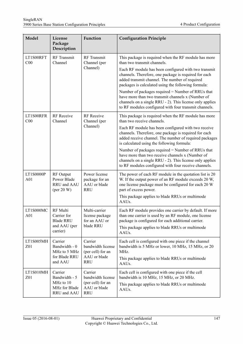
Model LicensePackageDescription
Function Configuration Principle
LT1S00RFTC00
RF TransmitChannel
RF TransmitChannel (perChannel)
This package is required when the RF module has morethan two transmit channels.Each RF module has been configured with two transmitchannels. Therefore, one package is required for eachadded transmit channel. The number of requiredpackages is calculated using the following formula:Number of packages required = Number of RRUs thathave more than two transmit channels x (Number ofchannels on a single RRU - 2). This license only appliesto RF modules configured with four transmit channels.
LT1S00RFRC00
RF ReceiveChannel
RF ReceiveChannel (perChannel)
This package is required when the RF module has morethan two receive channels.Each RF module has been configured with two receivechannels. Therefore, one package is required for eachadded receive channel. The number of required packagesis calculated using the following formula:Number of packages required = Number of RRUs thathave more than two receive channels x (Number ofchannels on a single RRU - 2). This license only appliesto RF modules configured with four receive channels.
LT1S0000PA01
RF OutputPower BladeRRU and AAU(per 20 W)
Power licensepackage for anAAU or bladeRRU
The power of each RF module in the quotation list is 20W. If the output power of an RF module exceeds 20 W,one license package must be configured for each 20 Wpart of excess power.This package applies to blade RRUs or multimodeAAUs.
LT1S000MCA01
RF MultiCarrier forBlade RRUand AAU (percarrier)
Multi-carrierlicense packagefor an AAU orblade RRU
Each RF module provides one carrier by default. If morethan one carrier is used by an RF module, one licensepackage is configured for each additional carrier.This package applies to blade RRUs or multimodeAAUs.
LT1S005MHZ01
CarrierBandwidth - 0MHz to 5 MHzfor Blade RRUand AAU
Carrierbandwidth license(per cell) for anAAU or bladeRRU
Each cell is configured with one piece if the channelbandwidth is 5 MHz or lower, 10 MHz, 15 MHz, or 20MHz.This package applies to blade RRUs or multimodeAAUs.
LT1S010MHZ01
CarrierBandwidth - 5MHz to 10MHz for BladeRRU and AAU
Carrierbandwidth license(per cell) for anAAU or bladeRRU
Each cell is configured with one piece if the cellbandwidth is 10 MHz, 15 MHz, or 20 MHz.This package applies to blade RRUs or multimodeAAUs.
SingleRAN3900 Series Base Station Configuration Principles 4 Product Configuration
Issue 05 (2016-08-01) Huawei Proprietary and ConfidentialCopyright © Huawei Technologies Co., Ltd.
147
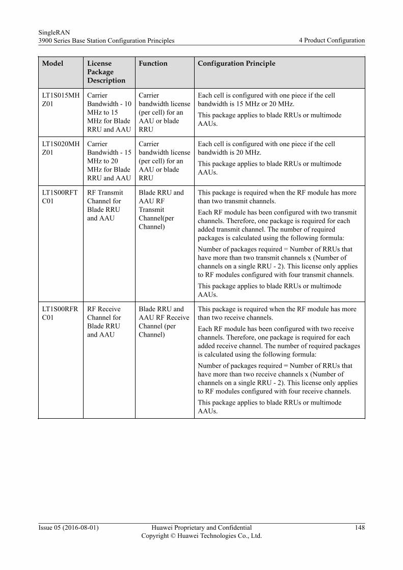
Model LicensePackageDescription
Function Configuration Principle
LT1S015MHZ01
CarrierBandwidth - 10MHz to 15MHz for BladeRRU and AAU
Carrierbandwidth license(per cell) for anAAU or bladeRRU
Each cell is configured with one piece if the cellbandwidth is 15 MHz or 20 MHz.This package applies to blade RRUs or multimodeAAUs.
LT1S020MHZ01
CarrierBandwidth - 15MHz to 20MHz for BladeRRU and AAU
Carrierbandwidth license(per cell) for anAAU or bladeRRU
Each cell is configured with one piece if the cellbandwidth is 20 MHz.This package applies to blade RRUs or multimodeAAUs.
LT1S00RFTC01
RF TransmitChannel forBlade RRUand AAU
Blade RRU andAAU RFTransmitChannel(perChannel)
This package is required when the RF module has morethan two transmit channels.Each RF module has been configured with two transmitchannels. Therefore, one package is required for eachadded transmit channel. The number of requiredpackages is calculated using the following formula:Number of packages required = Number of RRUs thathave more than two transmit channels x (Number ofchannels on a single RRU - 2). This license only appliesto RF modules configured with four transmit channels.This package applies to blade RRUs or multimodeAAUs.
LT1S00RFRC01
RF ReceiveChannel forBlade RRUand AAU
Blade RRU andAAU RF ReceiveChannel (perChannel)
This package is required when the RF module has morethan two receive channels.Each RF module has been configured with two receivechannels. Therefore, one package is required for eachadded receive channel. The number of required packagesis calculated using the following formula:Number of packages required = Number of RRUs thathave more than two receive channels x (Number ofchannels on a single RRU - 2). This license only appliesto RF modules configured with four receive channels.This package applies to blade RRUs or multimodeAAUs.
SingleRAN3900 Series Base Station Configuration Principles 4 Product Configuration
Issue 05 (2016-08-01) Huawei Proprietary and ConfidentialCopyright © Huawei Technologies Co., Ltd.
148
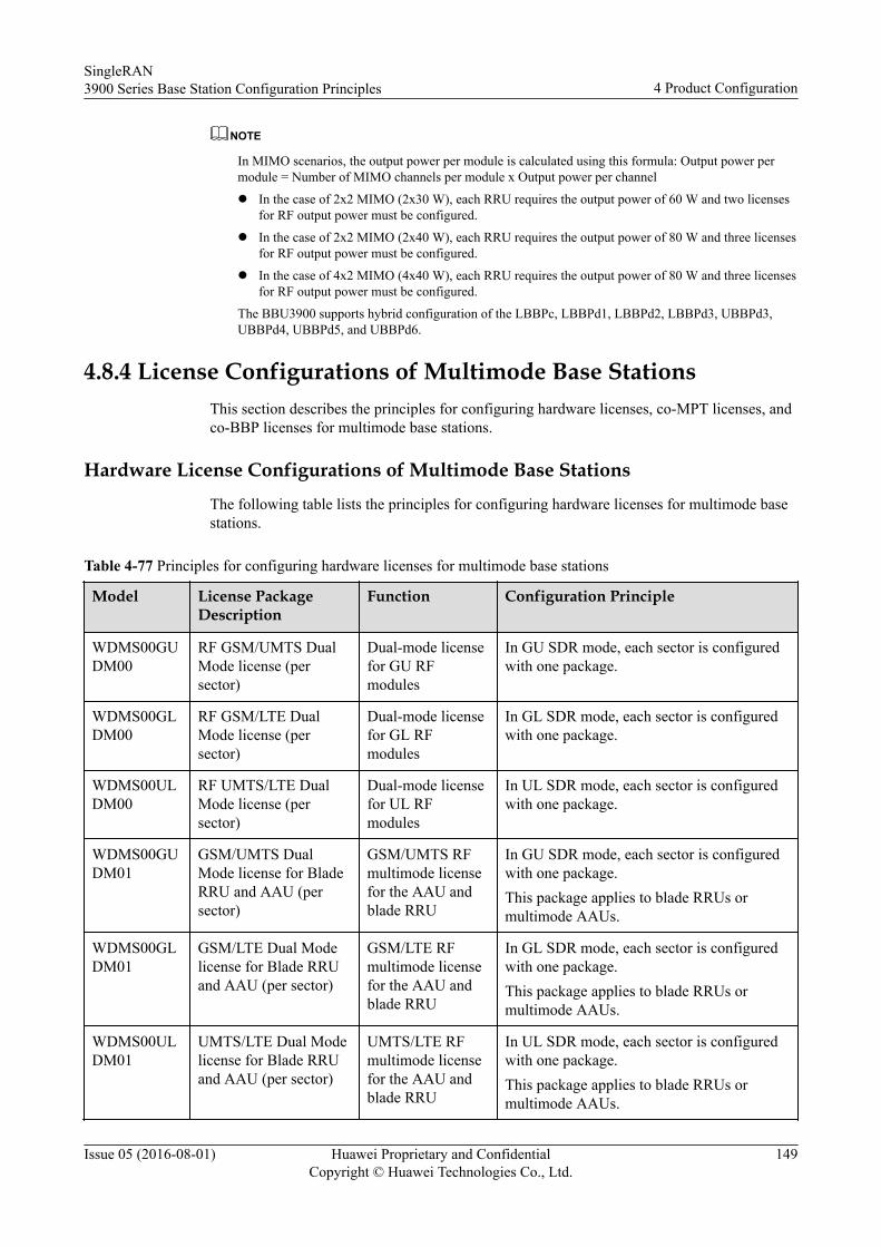
NOTE
In MIMO scenarios, the output power per module is calculated using this formula: Output power permodule = Number of MIMO channels per module x Output power per channel
l In the case of 2x2 MIMO (2x30 W), each RRU requires the output power of 60 W and two licensesfor RF output power must be configured.
l In the case of 2x2 MIMO (2x40 W), each RRU requires the output power of 80 W and three licensesfor RF output power must be configured.
l In the case of 4x2 MIMO (4x40 W), each RRU requires the output power of 80 W and three licensesfor RF output power must be configured.
The BBU3900 supports hybrid configuration of the LBBPc, LBBPd1, LBBPd2, LBBPd3, UBBPd3,UBBPd4, UBBPd5, and UBBPd6.
4.8.4 License Configurations of Multimode Base StationsThis section describes the principles for configuring hardware licenses, co-MPT licenses, andco-BBP licenses for multimode base stations.
Hardware License Configurations of Multimode Base Stations
The following table lists the principles for configuring hardware licenses for multimode basestations.
Table 4-77 Principles for configuring hardware licenses for multimode base stations
Model License PackageDescription
Function Configuration Principle
WDMS00GUDM00
RF GSM/UMTS DualMode license (persector)
Dual-mode licensefor GU RFmodules
In GU SDR mode, each sector is configuredwith one package.
WDMS00GLDM00
RF GSM/LTE DualMode license (persector)
Dual-mode licensefor GL RFmodules
In GL SDR mode, each sector is configuredwith one package.
WDMS00ULDM00
RF UMTS/LTE DualMode license (persector)
Dual-mode licensefor UL RFmodules
In UL SDR mode, each sector is configuredwith one package.
WDMS00GUDM01
GSM/UMTS DualMode license for BladeRRU and AAU (persector)
GSM/UMTS RFmultimode licensefor the AAU andblade RRU
In GU SDR mode, each sector is configuredwith one package.This package applies to blade RRUs ormultimode AAUs.
WDMS00GLDM01
GSM/LTE Dual Modelicense for Blade RRUand AAU (per sector)
GSM/LTE RFmultimode licensefor the AAU andblade RRU
In GL SDR mode, each sector is configuredwith one package.This package applies to blade RRUs ormultimode AAUs.
WDMS00ULDM01
UMTS/LTE Dual Modelicense for Blade RRUand AAU (per sector)
UMTS/LTE RFmultimode licensefor the AAU andblade RRU
In UL SDR mode, each sector is configuredwith one package.This package applies to blade RRUs ormultimode AAUs.
SingleRAN3900 Series Base Station Configuration Principles 4 Product Configuration
Issue 05 (2016-08-01) Huawei Proprietary and ConfidentialCopyright © Huawei Technologies Co., Ltd.
149
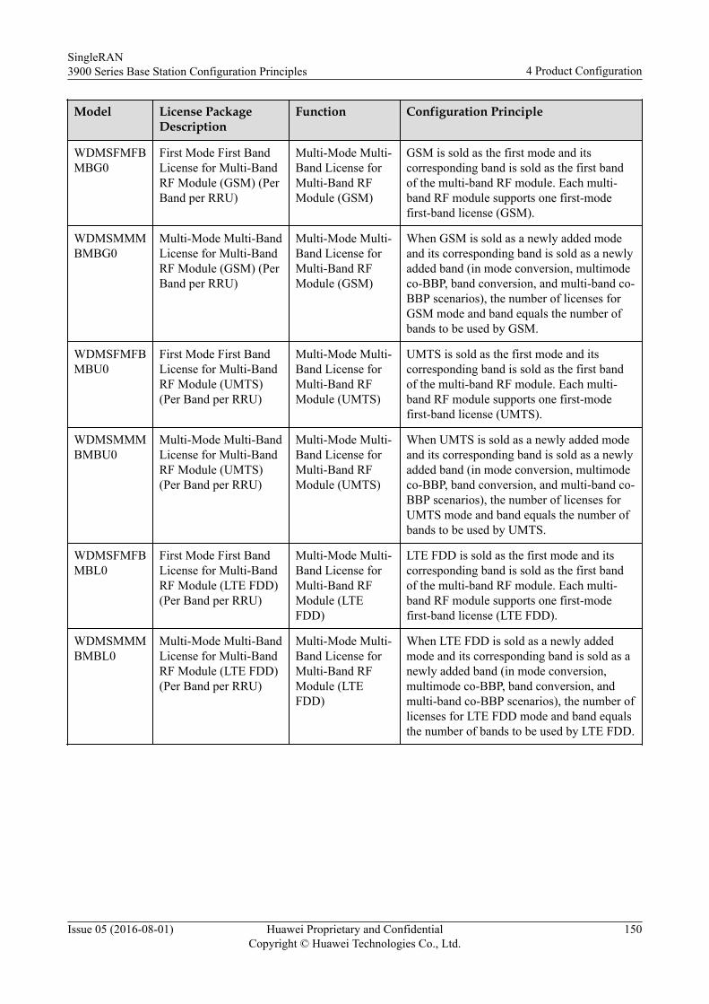
Model License PackageDescription
Function Configuration Principle
WDMSFMFBMBG0
First Mode First BandLicense for Multi-BandRF Module (GSM) (PerBand per RRU)
Multi-Mode Multi-Band License forMulti-Band RFModule (GSM)
GSM is sold as the first mode and itscorresponding band is sold as the first bandof the multi-band RF module. Each multi-band RF module supports one first-modefirst-band license (GSM).
WDMSMMMBMBG0
Multi-Mode Multi-BandLicense for Multi-BandRF Module (GSM) (PerBand per RRU)
Multi-Mode Multi-Band License forMulti-Band RFModule (GSM)
When GSM is sold as a newly added modeand its corresponding band is sold as a newlyadded band (in mode conversion, multimodeco-BBP, band conversion, and multi-band co-BBP scenarios), the number of licenses forGSM mode and band equals the number ofbands to be used by GSM.
WDMSFMFBMBU0
First Mode First BandLicense for Multi-BandRF Module (UMTS)(Per Band per RRU)
Multi-Mode Multi-Band License forMulti-Band RFModule (UMTS)
UMTS is sold as the first mode and itscorresponding band is sold as the first bandof the multi-band RF module. Each multi-band RF module supports one first-modefirst-band license (UMTS).
WDMSMMMBMBU0
Multi-Mode Multi-BandLicense for Multi-BandRF Module (UMTS)(Per Band per RRU)
Multi-Mode Multi-Band License forMulti-Band RFModule (UMTS)
When UMTS is sold as a newly added modeand its corresponding band is sold as a newlyadded band (in mode conversion, multimodeco-BBP, band conversion, and multi-band co-BBP scenarios), the number of licenses forUMTS mode and band equals the number ofbands to be used by UMTS.
WDMSFMFBMBL0
First Mode First BandLicense for Multi-BandRF Module (LTE FDD)(Per Band per RRU)
Multi-Mode Multi-Band License forMulti-Band RFModule (LTEFDD)
LTE FDD is sold as the first mode and itscorresponding band is sold as the first bandof the multi-band RF module. Each multi-band RF module supports one first-modefirst-band license (LTE FDD).
WDMSMMMBMBL0
Multi-Mode Multi-BandLicense for Multi-BandRF Module (LTE FDD)(Per Band per RRU)
Multi-Mode Multi-Band License forMulti-Band RFModule (LTEFDD)
When LTE FDD is sold as a newly addedmode and its corresponding band is sold as anewly added band (in mode conversion,multimode co-BBP, band conversion, andmulti-band co-BBP scenarios), the number oflicenses for LTE FDD mode and band equalsthe number of bands to be used by LTE FDD.
SingleRAN3900 Series Base Station Configuration Principles 4 Product Configuration
Issue 05 (2016-08-01) Huawei Proprietary and ConfidentialCopyright © Huawei Technologies Co., Ltd.
150
NOTE
(1) For deployment of a single mode and a single band, the First Mode First Band License for Multi-Band RF Module must be quoted for each multi-band module.(2) For deployment of multiple modes and multiple bands, first purchase licenses (Multi-Mode Multi-Band License for Multi-Band RF Module) for the latest mode, then licenses (First Mode First BandLicense for Multi-Band RF Module) for the earliest mode on each wideband module, and finallylicenses for the second earliest mode. By default, the modes are arranged from the earliest to the latest inthe following sequence: GSM < UMTS < LTE (FDD).(3) For the mode or band conversion scenarios, purchase licenses for the newly added mode according tothe number of bands used by the newly added mode.(4) Deployment of single-frequency triple-mode concurrency: Purchase GSM/UMTS and GSM/LTEdual-mode licenses for the single-frequency triple-mode cells to be deployed. The license combinationto be purchased is either of the following ones: RF GSM/UMTS Dual Mode license and RF GSM/LTEDual Mode license, or GSM/UMTS Dual Mode license for Blade RRU and AAU and GSM/LTE DualMode license for Blade RRU and AAU.(5) For capacity expansion of triple modes and a single band, purchase dual-mode licenses for the newlyadded mode according to the dual-mode licenses that have been purchased.l If a GU dual-mode license (RF GSM/UMTS Dual Mode license or GSM/UMTS Dual Mode
license for Blade RRU and AAU) has been purchased, purchase a GL dual-mode license (RFGSM/LTE Dual Mode license or GSM/LTE Dual Mode license for Blade RRU and AAU).
l If a GL dual-mode license (RF GSM/LTE Dual Mode license or GSM/LTE Dual Mode license forBlade RRU and AAU) has been purchased, purchase a GU dual-mode license (RF GSM/UMTSDual Mode license or GSM/UMTS Dual Mode license for Blade RRU and AAU).
(6) For the SDR module supporting inter-frequency mutual aid, if a single mode is in the transmitchannel, the multimode license is not required. For example, if LTE mode is in the transmit channelwhile UMTS mode is in the receive channel, this module is regarded as an LTE only module supportingLTE and the multimode license is not required.
Co-MPT License Configurations of Multimode Base StationsThe following table lists the principles for configuring co-MPT licenses for multimode basestations.
Table 4-78 Principles for configuring co-MPT licenses for multimode base stations
Model License PackageDescription
Function Configuration Principle
WDMS0UMMG00
MPT Multi Modelicense (GSM) (PerUMPT)
Co-MPTlicense forGSM
The number of GSM license supported by eachUMPT(1): Each base station is configured with amaximum of one such license.
WDMS0UMMU00
MPT Multi Modelicense (UMTS) (PerUMPT)
Co-MPTlicense forUMTS
The number of UMTS license supported by eachUMPT(1): Each base station is configured with amaximum of one such license.
WDMS0UMML00
MPT Multi Modelicense (LTE FDD)(Per UMPT)
Co-MPTlicense forLTE
This license indicates the number of LTE modessupported by each UMPT(1). Each base station isconfigured with a maximum of one LTE FDD co-MPT license.
LT1UMPTMMS00
MPT Multi Modelicense (LTE TDD)(per UMPT)
Co-MPTlicense forLTE
The number of LTE license supported by eachUMPT(1): Each base station is configured with amaximum of one LTE TDD co-MPT license.
SingleRAN3900 Series Base Station Configuration Principles 4 Product Configuration
Issue 05 (2016-08-01) Huawei Proprietary and ConfidentialCopyright © Huawei Technologies Co., Ltd.
151
NOTE
(1) Each UMPT supports one mode by default. One license needs to be added for each additional mode.When multiple modes are configured on a UMPT, first quote a UMPT for the earliest mode and then addlicenses for later modes. The GSM, UMTS, and LTE modes are arranged from the earliest to the latest asfollows: GSM < UMTS < LTE (FDD) < LTE (TDD).
Co-BBP License Configurations of Multimode Base StationsThe following table lists the principles for configuring co-BBP licenses for multimode basestations.
Table 4-79 Principles for configuring co-BBP licenses for multimode base stations
Model LicensePackageDescription
Function Configuration Principle
WDMS00UFMG00
UBBP First-Mode license(GSM) (PerUBBP)
License for the firstmode (GSM) of theUBBP
When GSM is used as the first mode, eachUBBP is configured with one such license.
WDMS00UMMG00
UBBP Multi-Mode license(GSM) (PerUBBP)
License for adding anew mode (GSM) ofthe UBBP
When GSM is added as a new mode (eitherreplacing the first mode or concurrent with thefirst mode), each UBBP is configured with onesuch license.
WDMS00UFMU00
UBBP First-Mode license(UMTS) (PerUBBP)
License for the firstmode (UMTS) ofthe UBBP
When UMTS is used as the first mode, eachUBBP is configured with one such license.
WDMS00UMMU00
UBBP Multi-Mode license(UMTS) (PerUBBP)
License for adding anew mode (UMTS)of the UBBP
When UMTS is added as a new mode (eitherreplacing the first mode or concurrent with thefirst mode), each UBBP is configured with onesuch license.
WDMS0UFMLF00
UBBP First-Mode license(LTE FDD) (perUBBP)
License for the firstmode (LTE FDD) ofthe UBBP
When LTE FDD is used as the first mode, eachUBBP is configured with one such license.
WDMS0UMMLF00
UBBP Multi-Mode license(LTE FDD) (PerUBBP)
License for adding anew mode (LTEFDD) of the UBBP
When LTE FDD is added as a new mode (eitherreplacing the first mode or concurrent with thefirst mode), each UBBP is configured with onesuch license.
LT1SUMMLFL01
UBBP First-Mode license(LTE TDD) (perUBBP)
License for the firstmode (LTE TDD) ofthe UBBP
When LTE TDD is used as the first mode, eachUBBP is configured with one first mode licensefor LTE TDD.
SingleRAN3900 Series Base Station Configuration Principles 4 Product Configuration
Issue 05 (2016-08-01) Huawei Proprietary and ConfidentialCopyright © Huawei Technologies Co., Ltd.
152
Model LicensePackageDescription
Function Configuration Principle
LT1SUMMLFL00
UBBP Multi-Mode license(LTE TDD) (perUBBP)
Multimode license(LTE TDD) of theUBBP
When LTE TDD is added as a new mode (eitherreplacing the first mode or concurrent with thefirst mode), each UBBP is configured with onemultimode license for LTE TDD.
(1) Deployment of a single mode: A first-mode license needs to be quoted for each single-mode UBBP.(2) Deployment of multimode concurrency: First purchase the multimode license for the latest mode and thenconfigure the first-mode license for the earliest mode. Different modes are arranged in the following sequencefrom the earliest to the latest: GSM < UMTS < LTE (FDD) < LTE (TDD).(3) Conversion of the mode: A multimode license needs to be purchased for the newly added mode in thisscenario, which involves converting one mode to another mode, converting a single mode to multimodeconcurrency, or adding a mode in a multimode concurrency scenario.
4.9 Equipment and Product Auxiliary MaterialConfiguration
This section describes the principles for configuring the installation and site auxiliarymaterials.
4.9.1 Installation Auxiliary MaterialsThis section describes the principles for configuring the auxiliary materials used for installing3900 series base stations.
Transmission Cables/Packages
The following table lists transmission cables and transmission packages for 3900 series macrobase stations.
Table 4-80 Installation auxiliary materials for 3900 series macro base stations
Model Description Function MaximumQuantity
Configuration Principle
QWMP0004E100
Trunk Cable (75Ohm, 4 E1, 10 m)
E1 electricalcable
- l It needs to be configured when 75 ohmE1 transmission or E1 line clock is used.
l One package is configured for every fourE1s.
QWMP0004E101
Trunk Cable (120Ohm, 4 E1, 10 m)
E1 electricalcable
- l It needs to be configured when 120 ohmE1 transmission or E1 line clock is used.
l One package is configured for every fourE1s.
SingleRAN3900 Series Base Station Configuration Principles 4 Product Configuration
Issue 05 (2016-08-01) Huawei Proprietary and ConfidentialCopyright © Huawei Technologies Co., Ltd.
153
Model Description Function MaximumQuantity
Configuration Principle
QWMP0000FE00
Ethernet Cable FE/GE fiberoptic cable
- l It needs to be configured when FE/GEelectrical ports are used.
l One package is configured for everyFE/GE.
LTIP000FBR00
Optical Fiber FE/GE fiberoptic cable
- l It needs to be configured when FE/GEoptical ports are used.
l One package is configured for everyFE/GE (only for Ver.B or Ver.C cabinets).
QWMP0000FE02
Optical Fiber (FE/STM-1)
FE/STM-1opticaltransmissionpackage
- l It needs to be configured when FE/STM-1 optical ports are used.
l One package is configured for every FE/STM-1 (only for Ver.D or Ver.Ecabinets).
QWMP0000GE00
Optical Fiber (GE) GE opticaltransmissionpackage
- l It needs to be configured when GEoptical ports are used.
l One package is configured for every GE(only for Ver.D or Ver.E cabinets).
QWMP0010GE00
10GE OpticalTransmissionMaterials
10GE opticaltransmissionpackage
- l It needs to be configured when 10GEoptical ports are used.
l One package is configured for each10GE.
l It is used for the BBU3900 andBBU3910.
The following table lists transmission cables and transmission packages for the DBS3900.
Table 4-81 Installation auxiliary materials for DBS3900 series base stations
Model Description Function MaximumQuantity
Configuration Principle
QWMP0004E100
Trunk Cable (75Ohm, 4 E1, 10 m)
E1 electricalcable
- l It needs to be configured when 75 ohmE1 transmission or E1 line clock is used.
l One package is configured for every fourE1s.
l It is used for the BBU3900 andBBU3910.
SingleRAN3900 Series Base Station Configuration Principles 4 Product Configuration
Issue 05 (2016-08-01) Huawei Proprietary and ConfidentialCopyright © Huawei Technologies Co., Ltd.
154
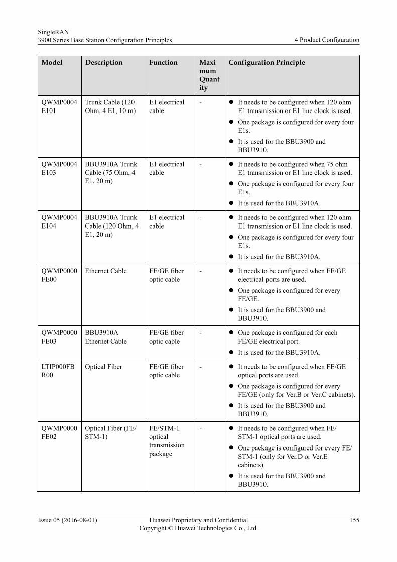
Model Description Function MaximumQuantity
Configuration Principle
QWMP0004E101
Trunk Cable (120Ohm, 4 E1, 10 m)
E1 electricalcable
- l It needs to be configured when 120 ohmE1 transmission or E1 line clock is used.
l One package is configured for every fourE1s.
l It is used for the BBU3900 andBBU3910.
QWMP0004E103
BBU3910A TrunkCable (75 Ohm, 4E1, 20 m)
E1 electricalcable
- l It needs to be configured when 75 ohmE1 transmission or E1 line clock is used.
l One package is configured for every fourE1s.
l It is used for the BBU3910A.
QWMP0004E104
BBU3910A TrunkCable (120 Ohm, 4E1, 20 m)
E1 electricalcable
- l It needs to be configured when 120 ohmE1 transmission or E1 line clock is used.
l One package is configured for every fourE1s.
l It is used for the BBU3910A.
QWMP0000FE00
Ethernet Cable FE/GE fiberoptic cable
- l It needs to be configured when FE/GEelectrical ports are used.
l One package is configured for everyFE/GE.
l It is used for the BBU3900 andBBU3910.
QWMP0000FE03
BBU3910AEthernet Cable
FE/GE fiberoptic cable
- l One package is configured for eachFE/GE electrical port.
l It is used for the BBU3910A.
LTIP000FBR00
Optical Fiber FE/GE fiberoptic cable
- l It needs to be configured when FE/GEoptical ports are used.
l One package is configured for everyFE/GE (only for Ver.B or Ver.C cabinets).
l It is used for the BBU3900 andBBU3910.
QWMP0000FE02
Optical Fiber (FE/STM-1)
FE/STM-1opticaltransmissionpackage
- l It needs to be configured when FE/STM-1 optical ports are used.
l One package is configured for every FE/STM-1 (only for Ver.D or Ver.Ecabinets).
l It is used for the BBU3900 andBBU3910.
SingleRAN3900 Series Base Station Configuration Principles 4 Product Configuration
Issue 05 (2016-08-01) Huawei Proprietary and ConfidentialCopyright © Huawei Technologies Co., Ltd.
155
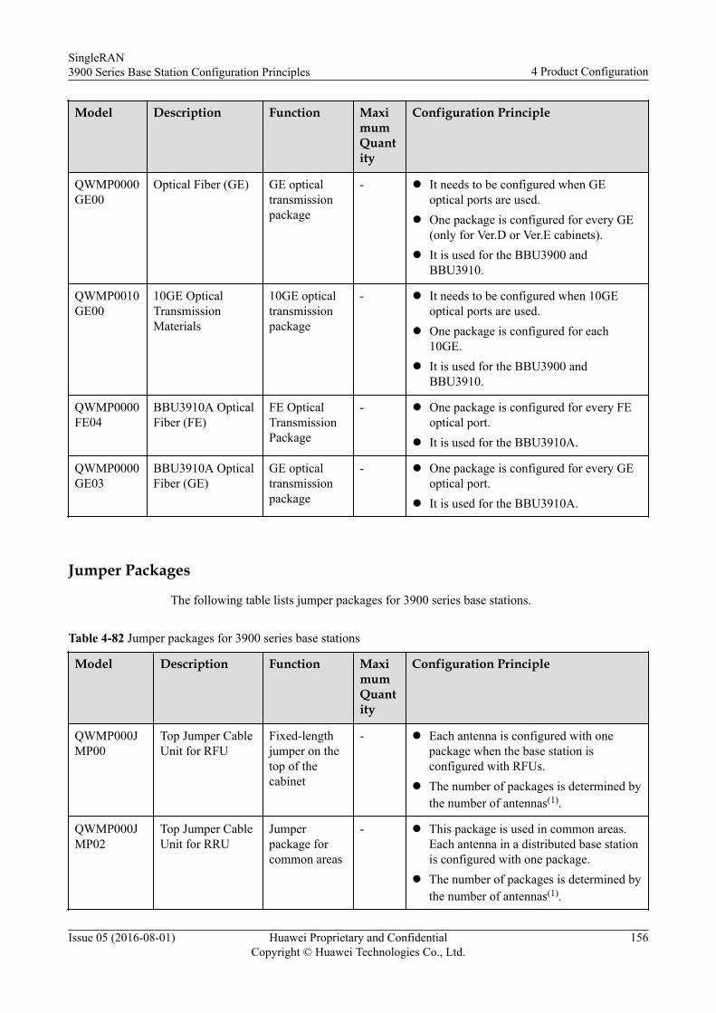
Model Description Function MaximumQuantity
Configuration Principle
QWMP0000GE00
Optical Fiber (GE) GE opticaltransmissionpackage
- l It needs to be configured when GEoptical ports are used.
l One package is configured for every GE(only for Ver.D or Ver.E cabinets).
l It is used for the BBU3900 andBBU3910.
QWMP0010GE00
10GE OpticalTransmissionMaterials
10GE opticaltransmissionpackage
- l It needs to be configured when 10GEoptical ports are used.
l One package is configured for each10GE.
l It is used for the BBU3900 andBBU3910.
QWMP0000FE04
BBU3910A OpticalFiber (FE)
FE OpticalTransmissionPackage
- l One package is configured for every FEoptical port.
l It is used for the BBU3910A.
QWMP0000GE03
BBU3910A OpticalFiber (GE)
GE opticaltransmissionpackage
- l One package is configured for every GEoptical port.
l It is used for the BBU3910A.
Jumper Packages
The following table lists jumper packages for 3900 series base stations.
Table 4-82 Jumper packages for 3900 series base stations
Model Description Function MaximumQuantity
Configuration Principle
QWMP000JMP00
Top Jumper CableUnit for RFU
Fixed-lengthjumper on thetop of thecabinet
- l Each antenna is configured with onepackage when the base station isconfigured with RFUs.
l The number of packages is determined bythe number of antennas(1).
QWMP000JMP02
Top Jumper CableUnit for RRU
Jumperpackage forcommon areas
- l This package is used in common areas.Each antenna in a distributed base stationis configured with one package.
l The number of packages is determined bythe number of antennas(1).
SingleRAN3900 Series Base Station Configuration Principles 4 Product Configuration
Issue 05 (2016-08-01) Huawei Proprietary and ConfidentialCopyright © Huawei Technologies Co., Ltd.
156
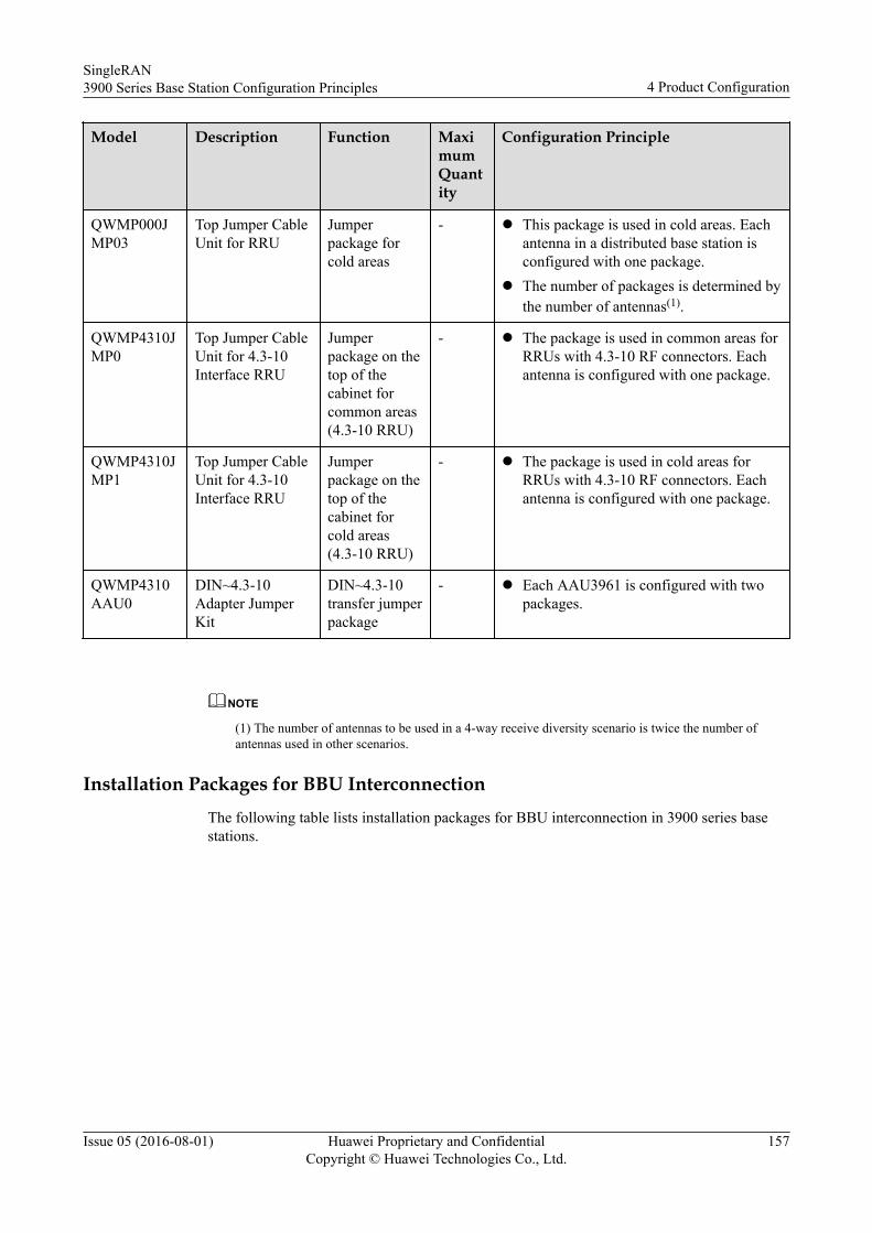
Model Description Function MaximumQuantity
Configuration Principle
QWMP000JMP03
Top Jumper CableUnit for RRU
Jumperpackage forcold areas
- l This package is used in cold areas. Eachantenna in a distributed base station isconfigured with one package.
l The number of packages is determined bythe number of antennas(1).
QWMP4310JMP0
Top Jumper CableUnit for 4.3-10Interface RRU
Jumperpackage on thetop of thecabinet forcommon areas(4.3-10 RRU)
- l The package is used in common areas forRRUs with 4.3-10 RF connectors. Eachantenna is configured with one package.
QWMP4310JMP1
Top Jumper CableUnit for 4.3-10Interface RRU
Jumperpackage on thetop of thecabinet forcold areas(4.3-10 RRU)
- l The package is used in cold areas forRRUs with 4.3-10 RF connectors. Eachantenna is configured with one package.
QWMP4310AAU0
DIN~4.3-10Adapter JumperKit
DIN~4.3-10transfer jumperpackage
- l Each AAU3961 is configured with twopackages.
NOTE
(1) The number of antennas to be used in a 4-way receive diversity scenario is twice the number ofantennas used in other scenarios.
Installation Packages for BBU InterconnectionThe following table lists installation packages for BBU interconnection in 3900 series basestations.
SingleRAN3900 Series Base Station Configuration Principles 4 Product Configuration
Issue 05 (2016-08-01) Huawei Proprietary and ConfidentialCopyright © Huawei Technologies Co., Ltd.
157
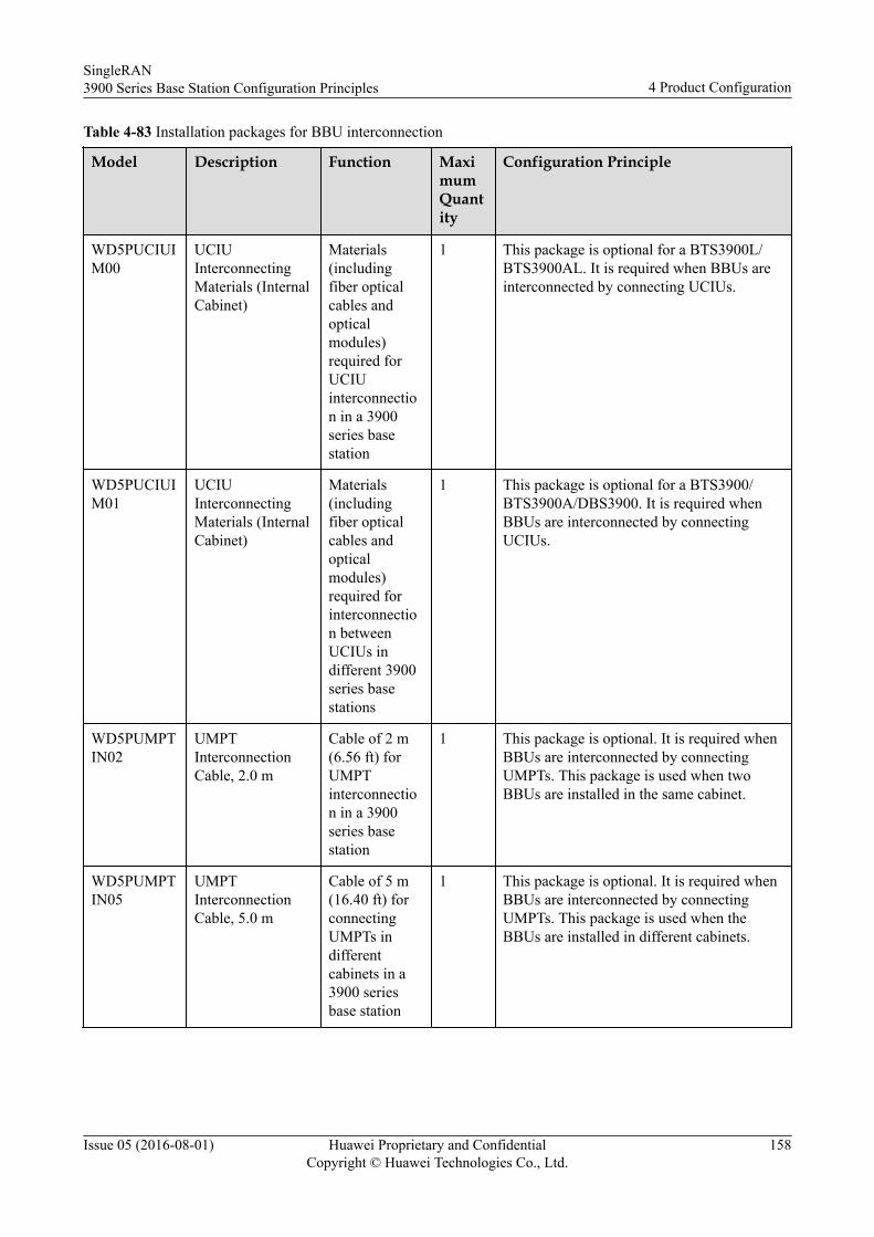
Table 4-83 Installation packages for BBU interconnection
Model Description Function MaximumQuantity
Configuration Principle
WD5PUCIUIM00
UCIUInterconnectingMaterials (InternalCabinet)
Materials(includingfiber opticalcables andopticalmodules)required forUCIUinterconnection in a 3900series basestation
1 This package is optional for a BTS3900L/BTS3900AL. It is required when BBUs areinterconnected by connecting UCIUs.
WD5PUCIUIM01
UCIUInterconnectingMaterials (InternalCabinet)
Materials(includingfiber opticalcables andopticalmodules)required forinterconnection betweenUCIUs indifferent 3900series basestations
1 This package is optional for a BTS3900/BTS3900A/DBS3900. It is required whenBBUs are interconnected by connectingUCIUs.
WD5PUMPTIN02
UMPTInterconnectionCable, 2.0 m
Cable of 2 m(6.56 ft) forUMPTinterconnection in a 3900series basestation
1 This package is optional. It is required whenBBUs are interconnected by connectingUMPTs. This package is used when twoBBUs are installed in the same cabinet.
WD5PUMPTIN05
UMPTInterconnectionCable, 5.0 m
Cable of 5 m(16.40 ft) forconnectingUMPTs indifferentcabinets in a3900 seriesbase station
1 This package is optional. It is required whenBBUs are interconnected by connectingUMPTs. This package is used when theBBUs are installed in different cabinets.
SingleRAN3900 Series Base Station Configuration Principles 4 Product Configuration
Issue 05 (2016-08-01) Huawei Proprietary and ConfidentialCopyright © Huawei Technologies Co., Ltd.
158
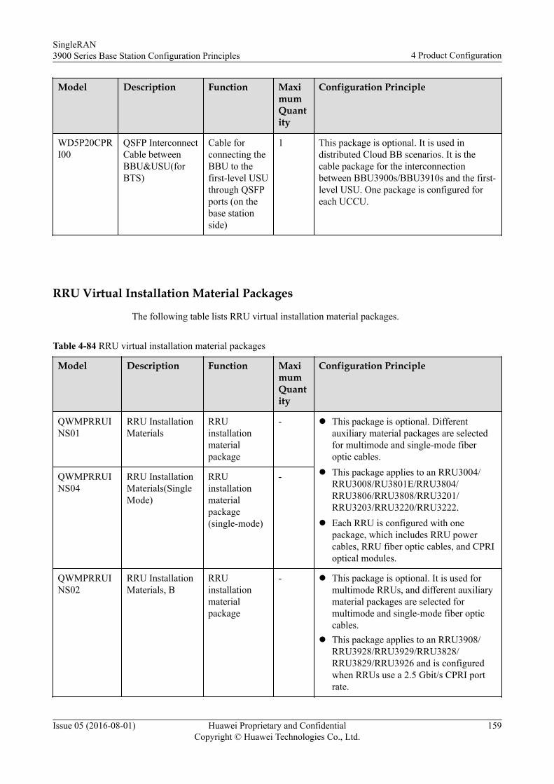
Model Description Function MaximumQuantity
Configuration Principle
WD5P20CPRI00
QSFP InterconnectCable betweenBBU&USU(forBTS)
Cable forconnecting theBBU to thefirst-level USUthrough QSFPports (on thebase stationside)
1 This package is optional. It is used indistributed Cloud BB scenarios. It is thecable package for the interconnectionbetween BBU3900s/BBU3910s and the first-level USU. One package is configured foreach UCCU.
RRU Virtual Installation Material Packages
The following table lists RRU virtual installation material packages.
Table 4-84 RRU virtual installation material packages
Model Description Function MaximumQuantity
Configuration Principle
QWMPRRUINS01
RRU InstallationMaterials
RRUinstallationmaterialpackage
- l This package is optional. Differentauxiliary material packages are selectedfor multimode and single-mode fiberoptic cables.
l This package applies to an RRU3004/RRU3008/RU3801E/RRU3804/RRU3806/RRU3808/RRU3201/RRU3203/RRU3220/RRU3222.
l Each RRU is configured with onepackage, which includes RRU powercables, RRU fiber optic cables, and CPRIoptical modules.
QWMPRRUINS04
RRU InstallationMaterials(SingleMode)
RRUinstallationmaterialpackage(single-mode)
-
QWMPRRUINS02
RRU InstallationMaterials, B
RRUinstallationmaterialpackage
- l This package is optional. It is used formultimode RRUs, and different auxiliarymaterial packages are selected formultimode and single-mode fiber opticcables.
l This package applies to an RRU3908/RRU3928/RRU3929/RRU3828/RRU3829/RRU3926 and is configuredwhen RRUs use a 2.5 Gbit/s CPRI portrate.
SingleRAN3900 Series Base Station Configuration Principles 4 Product Configuration
Issue 05 (2016-08-01) Huawei Proprietary and ConfidentialCopyright © Huawei Technologies Co., Ltd.
159
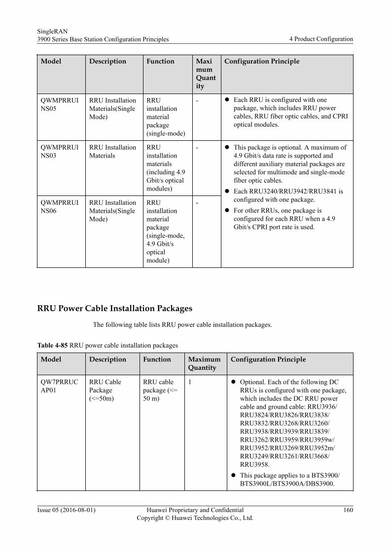
Model Description Function MaximumQuantity
Configuration Principle
QWMPRRUINS05
RRU InstallationMaterials(SingleMode)
RRUinstallationmaterialpackage(single-mode)
- l Each RRU is configured with onepackage, which includes RRU powercables, RRU fiber optic cables, and CPRIoptical modules.
QWMPRRUINS03
RRU InstallationMaterials
RRUinstallationmaterials(including 4.9Gbit/s opticalmodules)
- l This package is optional. A maximum of4.9 Gbit/s data rate is supported anddifferent auxiliary material packages areselected for multimode and single-modefiber optic cables.
l Each RRU3240/RRU3942/RRU3841 isconfigured with one package.
l For other RRUs, one package isconfigured for each RRU when a 4.9Gbit/s CPRI port rate is used.
QWMPRRUINS06
RRU InstallationMaterials(SingleMode)
RRUinstallationmaterialpackage(single-mode,4.9 Gbit/sopticalmodule)
-
RRU Power Cable Installation Packages
The following table lists RRU power cable installation packages.
Table 4-85 RRU power cable installation packages
Model Description Function MaximumQuantity
Configuration Principle
QW7PRRUCAP01
RRU CablePackage(<=50m)
RRU cablepackage (<=50 m)
1 l Optional. Each of the following DCRRUs is configured with one package,which includes the DC RRU powercable and ground cable: RRU3936/RRU3824/RRU3826/RRU3838/RRU3832/RRU3268/RRU3260/RRU3938/RRU3939/RRU3839/RRU3262/RRU3959/RRU3959w/RRU3952/RRU3269/RRU3952m/RRU3249/RRU3261/RRU3668/RRU3958.
l This package applies to a BTS3900/BTS3900L/BTS3900A/DBS3900.
SingleRAN3900 Series Base Station Configuration Principles 4 Product Configuration
Issue 05 (2016-08-01) Huawei Proprietary and ConfidentialCopyright © Huawei Technologies Co., Ltd.
160
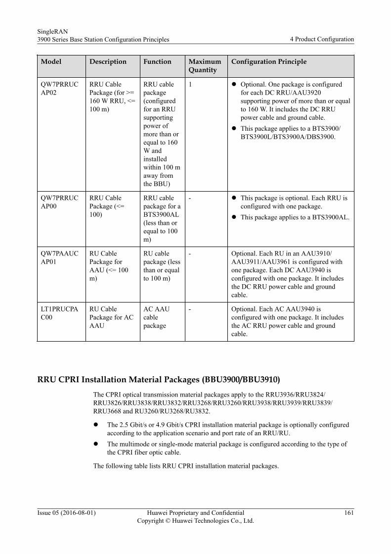
Model Description Function MaximumQuantity
Configuration Principle
QW7PRRUCAP02
RRU CablePackage (for >=160 W RRU, <=100 m)
RRU cablepackage(configuredfor an RRUsupportingpower ofmore than orequal to 160W andinstalledwithin 100 maway fromthe BBU)
1 l Optional. One package is configuredfor each DC RRU/AAU3920supporting power of more than or equalto 160 W. It includes the DC RRUpower cable and ground cable.
l This package applies to a BTS3900/BTS3900L/BTS3900A/DBS3900.
QW7PRRUCAP00
RRU CablePackage (<=100)
RRU cablepackage for aBTS3900AL(less than orequal to 100m)
- l This package is optional. Each RRU isconfigured with one package.
l This package applies to a BTS3900AL.
QW7PAAUCAP01
RU CablePackage forAAU (<= 100m)
RU cablepackage (lessthan or equalto 100 m)
- Optional. Each RU in an AAU3910/AAU3911/AAU3961 is configured withone package. Each DC AAU3940 isconfigured with one package. It includesthe DC RRU power cable and groundcable.
LT1PRUCPAC00
RU CablePackage for ACAAU
AC AAUcablepackage
- Optional. Each AC AAU3940 isconfigured with one package. It includesthe AC RRU power cable and groundcable.
RRU CPRI Installation Material Packages (BBU3900/BBU3910)The CPRI optical transmission material packages apply to the RRU3936/RRU3824/RRU3826/RRU3838/RRU3832/RRU3268/RRU3260/RRU3938/RRU3939/RRU3839/RRU3668 and RU3260/RU3268/RU3832.
l The 2.5 Gbit/s or 4.9 Gbit/s CPRI installation material package is optionally configuredaccording to the application scenario and port rate of an RRU/RU.
l The multimode or single-mode material package is configured according to the type ofthe CPRI fiber optic cable.
The following table lists RRU CPRI installation material packages.
SingleRAN3900 Series Base Station Configuration Principles 4 Product Configuration
Issue 05 (2016-08-01) Huawei Proprietary and ConfidentialCopyright © Huawei Technologies Co., Ltd.
161
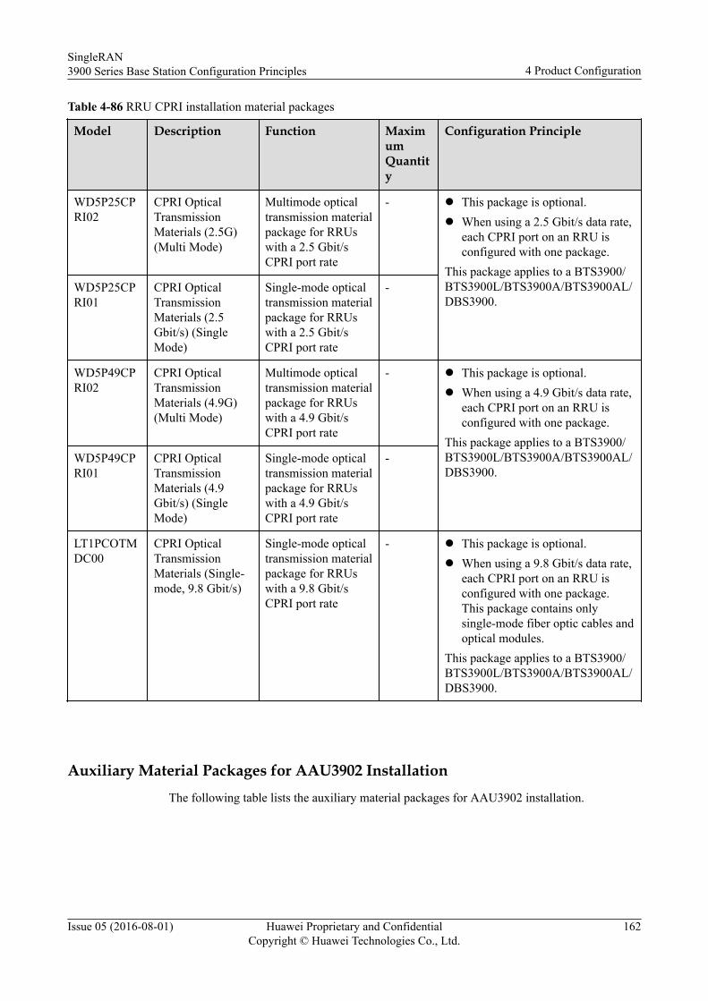
Table 4-86 RRU CPRI installation material packages
Model Description Function MaximumQuantity
Configuration Principle
WD5P25CPRI02
CPRI OpticalTransmissionMaterials (2.5G)(Multi Mode)
Multimode opticaltransmission materialpackage for RRUswith a 2.5 Gbit/sCPRI port rate
- l This package is optional.l When using a 2.5 Gbit/s data rate,
each CPRI port on an RRU isconfigured with one package.
This package applies to a BTS3900/BTS3900L/BTS3900A/BTS3900AL/DBS3900.
WD5P25CPRI01
CPRI OpticalTransmissionMaterials (2.5Gbit/s) (SingleMode)
Single-mode opticaltransmission materialpackage for RRUswith a 2.5 Gbit/sCPRI port rate
-
WD5P49CPRI02
CPRI OpticalTransmissionMaterials (4.9G)(Multi Mode)
Multimode opticaltransmission materialpackage for RRUswith a 4.9 Gbit/sCPRI port rate
- l This package is optional.l When using a 4.9 Gbit/s data rate,
each CPRI port on an RRU isconfigured with one package.
This package applies to a BTS3900/BTS3900L/BTS3900A/BTS3900AL/DBS3900.
WD5P49CPRI01
CPRI OpticalTransmissionMaterials (4.9Gbit/s) (SingleMode)
Single-mode opticaltransmission materialpackage for RRUswith a 4.9 Gbit/sCPRI port rate
-
LT1PCOTMDC00
CPRI OpticalTransmissionMaterials (Single-mode, 9.8 Gbit/s)
Single-mode opticaltransmission materialpackage for RRUswith a 9.8 Gbit/sCPRI port rate
- l This package is optional.l When using a 9.8 Gbit/s data rate,
each CPRI port on an RRU isconfigured with one package.This package contains onlysingle-mode fiber optic cables andoptical modules.
This package applies to a BTS3900/BTS3900L/BTS3900A/BTS3900AL/DBS3900.
Auxiliary Material Packages for AAU3902 InstallationThe following table lists the auxiliary material packages for AAU3902 installation.
SingleRAN3900 Series Base Station Configuration Principles 4 Product Configuration
Issue 05 (2016-08-01) Huawei Proprietary and ConfidentialCopyright © Huawei Technologies Co., Ltd.
162
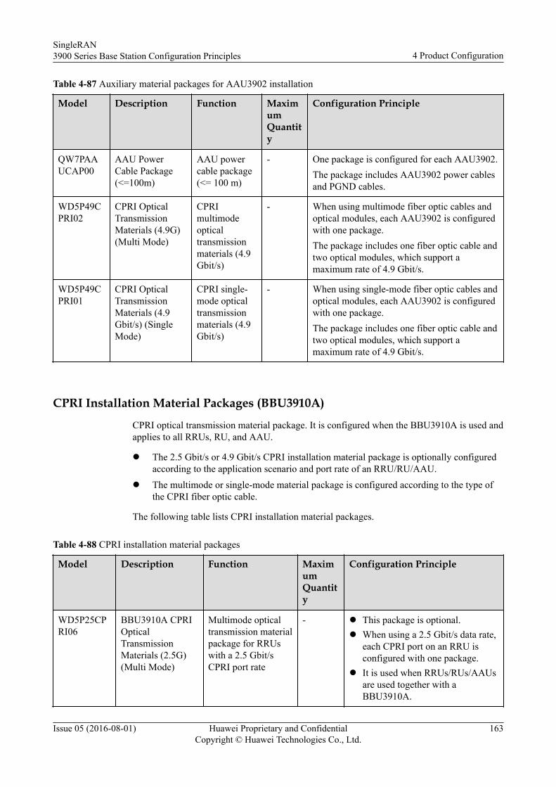
Table 4-87 Auxiliary material packages for AAU3902 installation
Model Description Function MaximumQuantity
Configuration Principle
QW7PAAUCAP00
AAU PowerCable Package(<=100m)
AAU powercable package(<= 100 m)
- One package is configured for each AAU3902.The package includes AAU3902 power cablesand PGND cables.
WD5P49CPRI02
CPRI OpticalTransmissionMaterials (4.9G)(Multi Mode)
CPRImultimodeopticaltransmissionmaterials (4.9Gbit/s)
- When using multimode fiber optic cables andoptical modules, each AAU3902 is configuredwith one package.The package includes one fiber optic cable andtwo optical modules, which support amaximum rate of 4.9 Gbit/s.
WD5P49CPRI01
CPRI OpticalTransmissionMaterials (4.9Gbit/s) (SingleMode)
CPRI single-mode opticaltransmissionmaterials (4.9Gbit/s)
- When using single-mode fiber optic cables andoptical modules, each AAU3902 is configuredwith one package.The package includes one fiber optic cable andtwo optical modules, which support amaximum rate of 4.9 Gbit/s.
CPRI Installation Material Packages (BBU3910A)
CPRI optical transmission material package. It is configured when the BBU3910A is used andapplies to all RRUs, RU, and AAU.
l The 2.5 Gbit/s or 4.9 Gbit/s CPRI installation material package is optionally configuredaccording to the application scenario and port rate of an RRU/RU/AAU.
l The multimode or single-mode material package is configured according to the type ofthe CPRI fiber optic cable.
The following table lists CPRI installation material packages.
Table 4-88 CPRI installation material packages
Model Description Function MaximumQuantity
Configuration Principle
WD5P25CPRI06
BBU3910A CPRIOpticalTransmissionMaterials (2.5G)(Multi Mode)
Multimode opticaltransmission materialpackage for RRUswith a 2.5 Gbit/sCPRI port rate
- l This package is optional.l When using a 2.5 Gbit/s data rate,
each CPRI port on an RRU isconfigured with one package.
l It is used when RRUs/RUs/AAUsare used together with aBBU3910A.
SingleRAN3900 Series Base Station Configuration Principles 4 Product Configuration
Issue 05 (2016-08-01) Huawei Proprietary and ConfidentialCopyright © Huawei Technologies Co., Ltd.
163
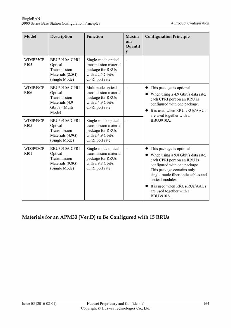
Model Description Function MaximumQuantity
Configuration Principle
WD5P25CPRI05
BBU3910A CPRIOpticalTransmissionMaterials (2.5G)(Single Mode)
Single-mode opticaltransmission materialpackage for RRUswith a 2.5 Gbit/sCPRI port rate
-
WD5P49CPRI06
BBU3910A CPRIOpticalTransmissionMaterials (4.9Gbit/s) (MultiMode)
Multimode opticaltransmission materialpackage for RRUswith a 4.9 Gbit/sCPRI port rate
- l This package is optional.l When using a 4.9 Gbit/s data rate,
each CPRI port on an RRU isconfigured with one package.
l It is used when RRUs/RUs/AAUsare used together with aBBU3910A.WD5P49CP
RI05BBU3910A CPRIOpticalTransmissionMaterials (4.9G)(Single Mode)
Single-mode opticaltransmission materialpackage for RRUswith a 4.9 Gbit/sCPRI port rate
-
WD5P98CPRI01
BBU3910A CPRIOpticalTransmissionMaterials (9.8G)(Single Mode)
Single-mode opticaltransmission materialpackage for RRUswith a 9.8 Gbit/sCPRI port rate
- l This package is optional.l When using a 9.8 Gbit/s data rate,
each CPRI port on an RRU isconfigured with one package.This package contains onlysingle-mode fiber optic cables andoptical modules.
l It is used when RRUs/RUs/AAUsare used together with aBBU3910A.
Materials for an APM30 (Ver.D) to Be Configured with 15 RRUs
SingleRAN3900 Series Base Station Configuration Principles 4 Product Configuration
Issue 05 (2016-08-01) Huawei Proprietary and ConfidentialCopyright © Huawei Technologies Co., Ltd.
164
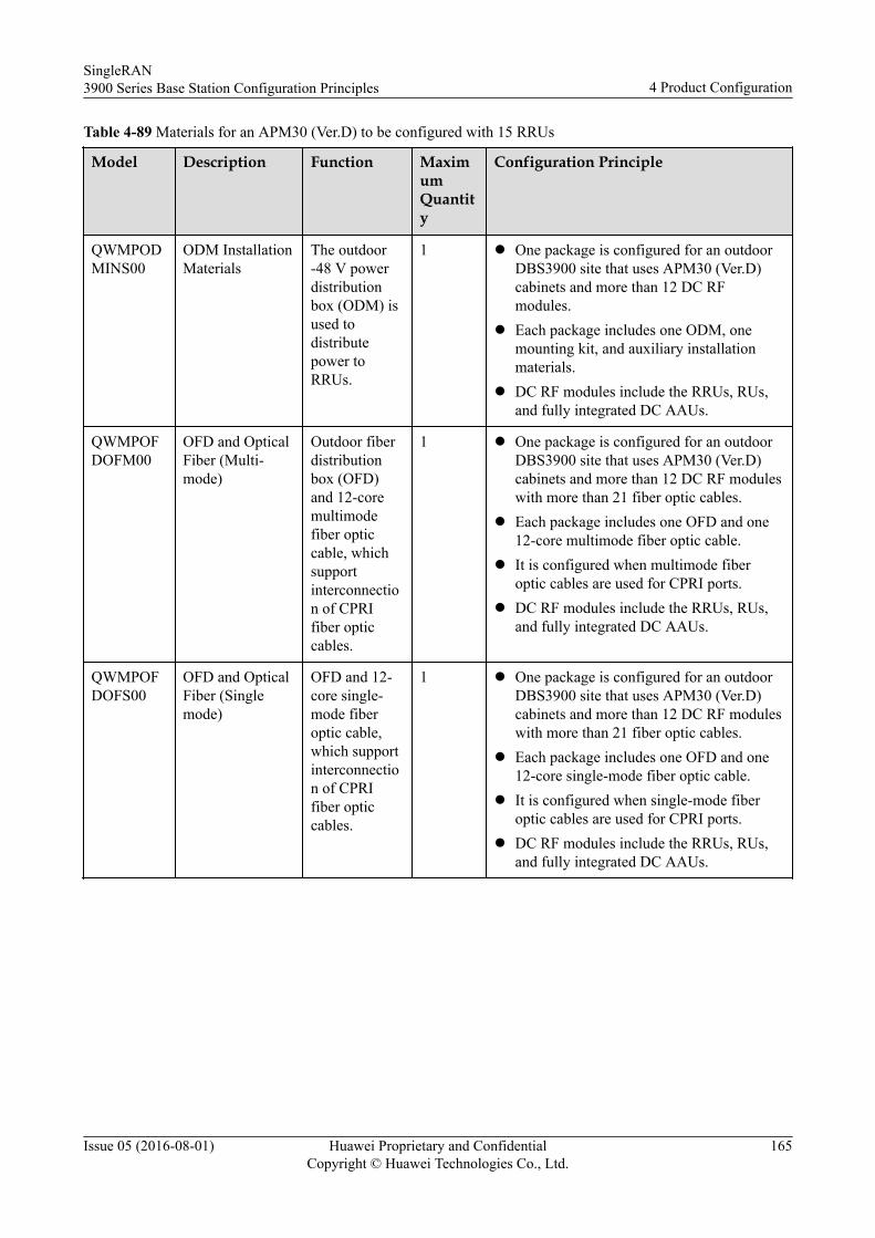
Table 4-89 Materials for an APM30 (Ver.D) to be configured with 15 RRUs
Model Description Function MaximumQuantity
Configuration Principle
QWMPODMINS00
ODM InstallationMaterials
The outdoor-48 V powerdistributionbox (ODM) isused todistributepower toRRUs.
1 l One package is configured for an outdoorDBS3900 site that uses APM30 (Ver.D)cabinets and more than 12 DC RFmodules.
l Each package includes one ODM, onemounting kit, and auxiliary installationmaterials.
l DC RF modules include the RRUs, RUs,and fully integrated DC AAUs.
QWMPOFDOFM00
OFD and OpticalFiber (Multi-mode)
Outdoor fiberdistributionbox (OFD)and 12-coremultimodefiber opticcable, whichsupportinterconnection of CPRIfiber opticcables.
1 l One package is configured for an outdoorDBS3900 site that uses APM30 (Ver.D)cabinets and more than 12 DC RF moduleswith more than 21 fiber optic cables.
l Each package includes one OFD and one12-core multimode fiber optic cable.
l It is configured when multimode fiberoptic cables are used for CPRI ports.
l DC RF modules include the RRUs, RUs,and fully integrated DC AAUs.
QWMPOFDOFS00
OFD and OpticalFiber (Singlemode)
OFD and 12-core single-mode fiberoptic cable,which supportinterconnection of CPRIfiber opticcables.
1 l One package is configured for an outdoorDBS3900 site that uses APM30 (Ver.D)cabinets and more than 12 DC RF moduleswith more than 21 fiber optic cables.
l Each package includes one OFD and one12-core single-mode fiber optic cable.
l It is configured when single-mode fiberoptic cables are used for CPRI ports.
l DC RF modules include the RRUs, RUs,and fully integrated DC AAUs.
SingleRAN3900 Series Base Station Configuration Principles 4 Product Configuration
Issue 05 (2016-08-01) Huawei Proprietary and ConfidentialCopyright © Huawei Technologies Co., Ltd.
165
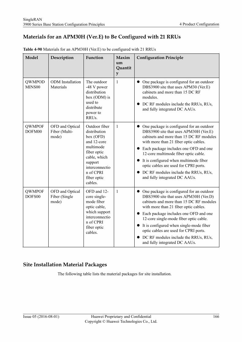
Materials for an APM30H (Ver.E) to Be Configured with 21 RRUs
Table 4-90 Materials for an APM30H (Ver.E) to be configured with 21 RRUs
Model Description Function MaximumQuantity
Configuration Principle
QWMPODMINS00
ODM InstallationMaterials
The outdoor-48 V powerdistributionbox (ODM) isused todistributepower toRRUs.
1 l One package is configured for an outdoorDBS3900 site that uses APM30 (Ver.E)cabinets and more than 15 DC RFmodules.
l DC RF modules include the RRUs, RUs,and fully integrated DC AAUs.
QWMPOFDOFM00
OFD and OpticalFiber (Multi-mode)
Outdoor fiberdistributionbox (OFD)and 12-coremultimodefiber opticcable, whichsupportinterconnection of CPRIfiber opticcables.
1 l One package is configured for an outdoorDBS3900 site that uses APM30H (Ver.E)cabinets and more than 15 DC RF moduleswith more than 21 fiber optic cables.
l Each package includes one OFD and one12-core multimode fiber optic cable.
l It is configured when multimode fiberoptic cables are used for CPRI ports.
l DC RF modules include the RRUs, RUs,and fully integrated DC AAUs.
QWMPOFDOFS00
OFD and OpticalFiber (Singlemode)
OFD and 12-core single-mode fiberoptic cable,which supportinterconnection of CPRIfiber opticcables.
1 l One package is configured for an outdoorDBS3900 site that uses APM30H (Ver.D)cabinets and more than 15 DC RF moduleswith more than 21 fiber optic cables.
l Each package includes one OFD and one12-core single-mode fiber optic cable.
l It is configured when single-mode fiberoptic cables are used for CPRI ports.
l DC RF modules include the RRUs, RUs,and fully integrated DC AAUs.
Site Installation Material PackagesThe following table lists the material packages for site installation.
SingleRAN3900 Series Base Station Configuration Principles 4 Product Configuration
Issue 05 (2016-08-01) Huawei Proprietary and ConfidentialCopyright © Huawei Technologies Co., Ltd.
166
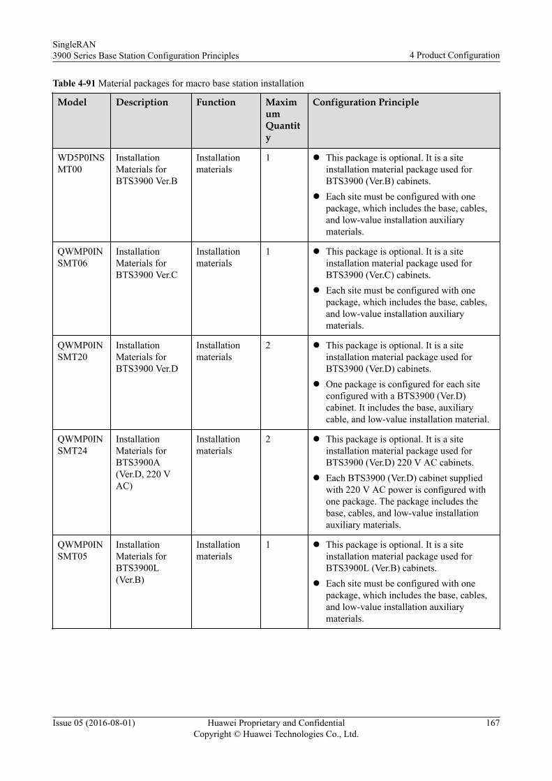
Table 4-91 Material packages for macro base station installation
Model Description Function MaximumQuantity
Configuration Principle
WD5P0INSMT00
InstallationMaterials forBTS3900 Ver.B
Installationmaterials
1 l This package is optional. It is a siteinstallation material package used forBTS3900 (Ver.B) cabinets.
l Each site must be configured with onepackage, which includes the base, cables,and low-value installation auxiliarymaterials.
QWMP0INSMT06
InstallationMaterials forBTS3900 Ver.C
Installationmaterials
1 l This package is optional. It is a siteinstallation material package used forBTS3900 (Ver.C) cabinets.
l Each site must be configured with onepackage, which includes the base, cables,and low-value installation auxiliarymaterials.
QWMP0INSMT20
InstallationMaterials forBTS3900 Ver.D
Installationmaterials
2 l This package is optional. It is a siteinstallation material package used forBTS3900 (Ver.D) cabinets.
l One package is configured for each siteconfigured with a BTS3900 (Ver.D)cabinet. It includes the base, auxiliarycable, and low-value installation material.
QWMP0INSMT24
InstallationMaterials forBTS3900A(Ver.D, 220 VAC)
Installationmaterials
2 l This package is optional. It is a siteinstallation material package used forBTS3900 (Ver.D) 220 V AC cabinets.
l Each BTS3900 (Ver.D) cabinet suppliedwith 220 V AC power is configured withone package. The package includes thebase, cables, and low-value installationauxiliary materials.
QWMP0INSMT05
InstallationMaterials forBTS3900L(Ver.B)
Installationmaterials
1 l This package is optional. It is a siteinstallation material package used forBTS3900L (Ver.B) cabinets.
l Each site must be configured with onepackage, which includes the base, cables,and low-value installation auxiliarymaterials.
SingleRAN3900 Series Base Station Configuration Principles 4 Product Configuration
Issue 05 (2016-08-01) Huawei Proprietary and ConfidentialCopyright © Huawei Technologies Co., Ltd.
167
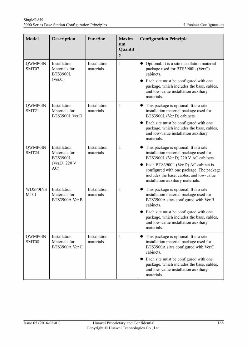
Model Description Function MaximumQuantity
Configuration Principle
QWMP0INSMT07
InstallationMaterials forBTS3900L(Ver.C)
Installationmaterials
1 l Optional. It is a site installation materialpackage used for BTS3900L (Ver.C)cabinets.
l Each site must be configured with onepackage, which includes the base, cables,and low-value installation auxiliarymaterials.
QWMP0INSMT21
InstallationMaterials forBTS3900L Ver.D
Installationmaterials
1 l This package is optional. It is a siteinstallation material package used forBTS3900L (Ver.D) cabinets.
l Each site must be configured with onepackage, which includes the base, cables,and low-value installation auxiliarymaterials.
QWMP0INSMT24
InstallationMaterials forBTS3900L(Ver.D, 220 VAC)
Installationmaterials
1 l This package is optional. It is a siteinstallation material package used forBTS3900L (Ver.D) 220 V AC cabinets.
l Each BTS3900L (Ver.D) AC cabinet isconfigured with one package. The packageincludes the base, cables, and low-valueinstallation auxiliary materials.
WD5P0INSMT01
InstallationMaterials forBTS3900A Ver.B
Installationmaterials
1 l This package is optional. It is a siteinstallation material package used forBTS3900A sites configured with Ver.Bcabinets.
l Each site must be configured with onepackage, which includes the base, cables,and low-value installation auxiliarymaterials.
QWMP0INSMT08
InstallationMaterials forBTS3900A Ver.C
Installationmaterials
1 l This package is optional. It is a siteinstallation material package used forBTS3900A sites configured with Ver.Ccabinets.
l Each site must be configured with onepackage, which includes the base, cables,and low-value installation auxiliarymaterials.
SingleRAN3900 Series Base Station Configuration Principles 4 Product Configuration
Issue 05 (2016-08-01) Huawei Proprietary and ConfidentialCopyright © Huawei Technologies Co., Ltd.
168
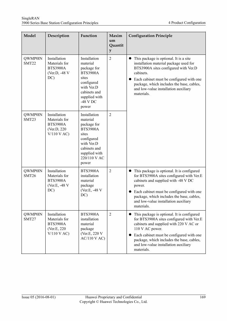
Model Description Function MaximumQuantity
Configuration Principle
QWMP0INSMT22
InstallationMaterials forBTS3900A(Ver.D, -48 VDC)
Installationmaterialpackage forBTS3900Asitesconfiguredwith Ver.Dcabinets andsupplied with-48 V DCpower
2 l This package is optional. It is a siteinstallation material package used forBTS3900A sites configured with Ver.Dcabinets.
l Each cabinet must be configured with onepackage, which includes the base, cables,and low-value installation auxiliarymaterials.
QWMP0INSMT23
InstallationMaterials forBTS3900A(Ver.D, 220V/110 V AC)
Installationmaterialpackage forBTS3900Asitesconfiguredwith Ver.Dcabinets andsupplied with220/110 V ACpower
2
QWMP0INSMT26
InstallationMaterials forBTS3900A(Ver.E, -48 VDC)
BTS3900Ainstallationmaterialpackage(Ver.E, -48 VDC)
2 l This package is optional. It is configuredfor BTS3900A sites configured with Ver.Ecabinets and supplied with -48 V DCpower.
l Each cabinet must be configured with onepackage, which includes the base, cables,and low-value installation auxiliarymaterials.
QWMP0INSMT27
InstallationMaterials forBTS3900A(Ver.E, 220V/110 V AC)
BTS3900Ainstallationmaterialpackage(Ver.E, 220 VAC/110 V AC)
2 l This package is optional. It is configuredfor BTS3900A sites configured with Ver.Ecabinets and supplied with 220 V AC or110 V AC power.
l Each cabinet must be configured with onepackage, which includes the base, cables,and low-value installation auxiliarymaterials.
SingleRAN3900 Series Base Station Configuration Principles 4 Product Configuration
Issue 05 (2016-08-01) Huawei Proprietary and ConfidentialCopyright © Huawei Technologies Co., Ltd.
169
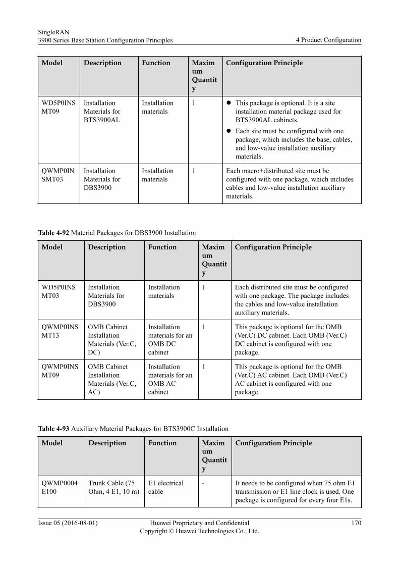
Model Description Function MaximumQuantity
Configuration Principle
WD5P0INSMT09
InstallationMaterials forBTS3900AL
Installationmaterials
1 l This package is optional. It is a siteinstallation material package used forBTS3900AL cabinets.
l Each site must be configured with onepackage, which includes the base, cables,and low-value installation auxiliarymaterials.
QWMP0INSMT03
InstallationMaterials forDBS3900
Installationmaterials
1 Each macro+distributed site must beconfigured with one package, which includescables and low-value installation auxiliarymaterials.
Table 4-92 Material Packages for DBS3900 Installation
Model Description Function MaximumQuantity
Configuration Principle
WD5P0INSMT03
InstallationMaterials forDBS3900
Installationmaterials
1 Each distributed site must be configuredwith one package. The package includesthe cables and low-value installationauxiliary materials.
QWMP0INSMT13
OMB CabinetInstallationMaterials (Ver.C,DC)
Installationmaterials for anOMB DCcabinet
1 This package is optional for the OMB(Ver.C) DC cabinet. Each OMB (Ver.C)DC cabinet is configured with onepackage.
QWMP0INSMT09
OMB CabinetInstallationMaterials (Ver.C,AC)
Installationmaterials for anOMB ACcabinet
1 This package is optional for the OMB(Ver.C) AC cabinet. Each OMB (Ver.C)AC cabinet is configured with onepackage.
Table 4-93 Auxiliary Material Packages for BTS3900C Installation
Model Description Function MaximumQuantity
Configuration Principle
QWMP0004E100
Trunk Cable (75Ohm, 4 E1, 10 m)
E1 electricalcable
- It needs to be configured when 75 ohm E1transmission or E1 line clock is used. Onepackage is configured for every four E1s.
SingleRAN3900 Series Base Station Configuration Principles 4 Product Configuration
Issue 05 (2016-08-01) Huawei Proprietary and ConfidentialCopyright © Huawei Technologies Co., Ltd.
170
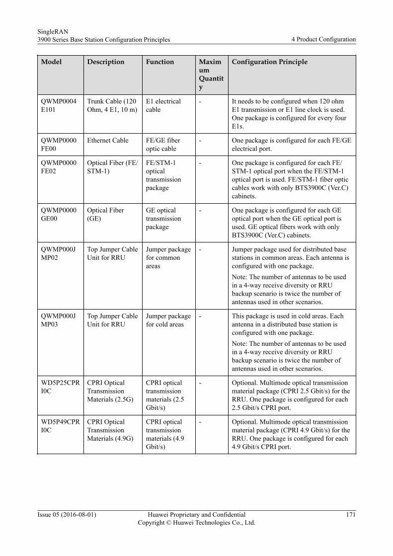
Model Description Function MaximumQuantity
Configuration Principle
QWMP0004E101
Trunk Cable (120Ohm, 4 E1, 10 m)
E1 electricalcable
- It needs to be configured when 120 ohmE1 transmission or E1 line clock is used.One package is configured for every fourE1s.
QWMP0000FE00
Ethernet Cable FE/GE fiberoptic cable
- One package is configured for each FE/GEelectrical port.
QWMP0000FE02
Optical Fiber (FE/STM-1)
FE/STM-1opticaltransmissionpackage
- One package is configured for each FE/STM-1 optical port when the FE/STM-1optical port is used. FE/STM-1 fiber opticcables work with only BTS3900C (Ver.C)cabinets.
QWMP0000GE00
Optical Fiber(GE)
GE opticaltransmissionpackage
- One package is configured for each GEoptical port when the GE optical port isused. GE optical fibers work with onlyBTS3900C (Ver.C) cabinets.
QWMP000JMP02
Top Jumper CableUnit for RRU
Jumper packagefor commonareas
- Jumper package used for distributed basestations in common areas. Each antenna isconfigured with one package.Note: The number of antennas to be usedin a 4-way receive diversity or RRUbackup scenario is twice the number ofantennas used in other scenarios.
QWMP000JMP03
Top Jumper CableUnit for RRU
Jumper packagefor cold areas
- This package is used in cold areas. Eachantenna in a distributed base station isconfigured with one package.Note: The number of antennas to be usedin a 4-way receive diversity or RRUbackup scenario is twice the number ofantennas used in other scenarios.
WD5P25CPRI0C
CPRI OpticalTransmissionMaterials (2.5G)
CPRI opticaltransmissionmaterials (2.5Gbit/s)
- Optional. Multimode optical transmissionmaterial package (CPRI 2.5 Gbit/s) for theRRU. One package is configured for each2.5 Gbit/s CPRI port.
WD5P49CPRI0C
CPRI OpticalTransmissionMaterials (4.9G)
CPRI opticaltransmissionmaterials (4.9Gbit/s)
- Optional. Multimode optical transmissionmaterial package (CPRI 4.9 Gbit/s) for theRRU. One package is configured for each4.9 Gbit/s CPRI port.
SingleRAN3900 Series Base Station Configuration Principles 4 Product Configuration
Issue 05 (2016-08-01) Huawei Proprietary and ConfidentialCopyright © Huawei Technologies Co., Ltd.
171
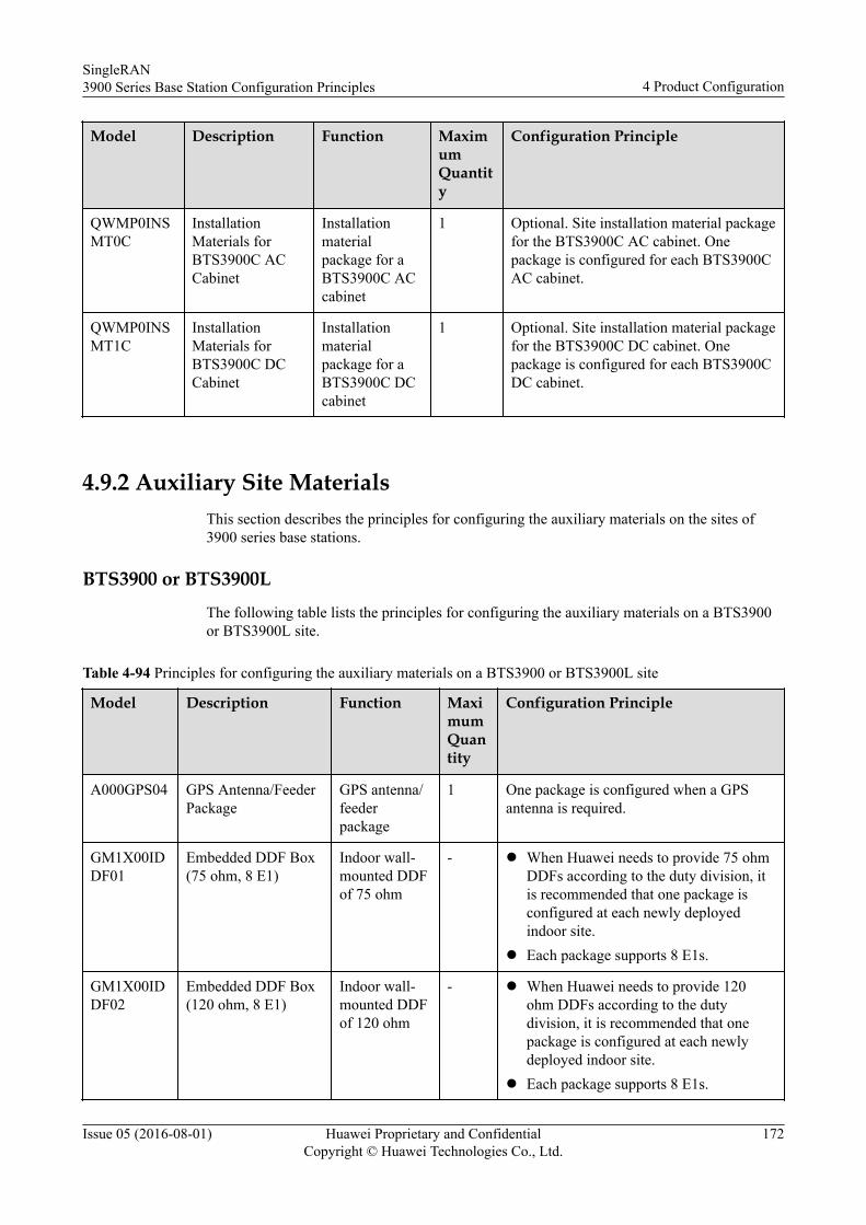
Model Description Function MaximumQuantity
Configuration Principle
QWMP0INSMT0C
InstallationMaterials forBTS3900C ACCabinet
Installationmaterialpackage for aBTS3900C ACcabinet
1 Optional. Site installation material packagefor the BTS3900C AC cabinet. Onepackage is configured for each BTS3900CAC cabinet.
QWMP0INSMT1C
InstallationMaterials forBTS3900C DCCabinet
Installationmaterialpackage for aBTS3900C DCcabinet
1 Optional. Site installation material packagefor the BTS3900C DC cabinet. Onepackage is configured for each BTS3900CDC cabinet.
4.9.2 Auxiliary Site MaterialsThis section describes the principles for configuring the auxiliary materials on the sites of3900 series base stations.
BTS3900 or BTS3900L
The following table lists the principles for configuring the auxiliary materials on a BTS3900or BTS3900L site.
Table 4-94 Principles for configuring the auxiliary materials on a BTS3900 or BTS3900L site
Model Description Function MaximumQuantity
Configuration Principle
A000GPS04 GPS Antenna/FeederPackage
GPS antenna/feederpackage
1 One package is configured when a GPSantenna is required.
GM1X00IDDF01
Embedded DDF Box(75 ohm, 8 E1)
Indoor wall-mounted DDFof 75 ohm
- l When Huawei needs to provide 75 ohmDDFs according to the duty division, itis recommended that one package isconfigured at each newly deployedindoor site.
l Each package supports 8 E1s.
GM1X00IDDF02
Embedded DDF Box(120 ohm, 8 E1)
Indoor wall-mounted DDFof 120 ohm
- l When Huawei needs to provide 120ohm DDFs according to the dutydivision, it is recommended that onepackage is configured at each newlydeployed indoor site.
l Each package supports 8 E1s.
SingleRAN3900 Series Base Station Configuration Principles 4 Product Configuration
Issue 05 (2016-08-01) Huawei Proprietary and ConfidentialCopyright © Huawei Technologies Co., Ltd.
172
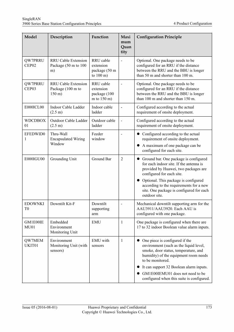
Model Description Function MaximumQuantity
Configuration Principle
QW7PRRUCEP02
RRU Cable ExtensionPackage (50 m to 100m)
RRU cableextensionpackage (50 mto 100 m)
- Optional. One package needs to beconfigured for an RRU if the distancebetween the RRU and the BBU is longerthan 50 m and shorter than 100 m.
QW7PRRUCEP03
RRU Cable ExtensionPackage (100 m to150 m)
RRU cableextensionpackage (100m to 150 m)
- Optional. One package needs to beconfigured for an RRU if the distancebetween the RRU and the BBU is longerthan 100 m and shorter than 150 m.
E000ICL00 Indoor Cable Ladder(2.5 m)
Indoor cableladder
- Configured according to the actualrequirement of onsite deployment.
WDCDBOX01
Outdoor Cable Ladder(2.5 m)
Outdoor cableladder
- Configured according to the actualrequirement of onsite deployment.
EFEDWID01
Thru-WallEncapsulated WiringWindow
Feederwindow
- l Configured according to the actualrequirement of onsite deployment.
l A maximum of one package can beconfigured for each site.
E000IGU00 Grounding Unit Ground Bar 2 l Ground bar. One package is configuredfor each indoor site. If the antenna isprovided by Huawei, two packages areconfigured for each site.
l Optional. This package is configuredaccording to the requirements for a newsite. One package is configured for eachoutdoor site.
EDOWNKIT0
Downtilt Kit-F Downtiltsupportingarm
- Mechanical downtilt supporting arm for theAAU3911/AAU3920. Each AAU isconfigured with one package.
GM1E00IEMU01
EmbeddedEnvironmentMonitoring Unit
EMU 1 One package is configured when there are17 to 32 indoor Boolean value alarm inputs.
QW7MEMUKIT01
EnvironmentMonitoring Unit (withsensors)
EMU withsensors
1 l One piece is configured if theenvironment (such as the liquid level,smoke, door status, temperature, andhumidity) of the equipment room needsto be monitored.
l It can support 32 Boolean alarm inputs.l GM1E00IEMU01 does not need to be
configured when this suite is configured.
SingleRAN3900 Series Base Station Configuration Principles 4 Product Configuration
Issue 05 (2016-08-01) Huawei Proprietary and ConfidentialCopyright © Huawei Technologies Co., Ltd.
173
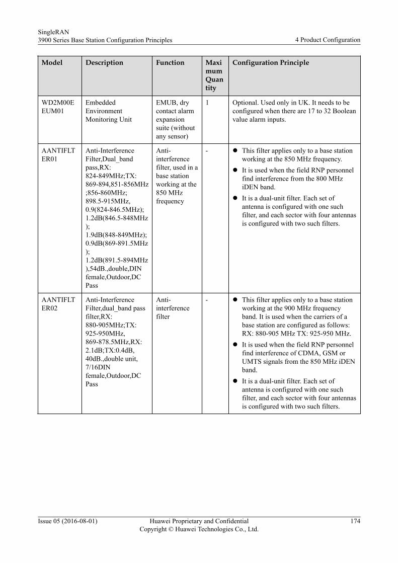
Model Description Function MaximumQuantity
Configuration Principle
WD2M00EEUM01
EmbeddedEnvironmentMonitoring Unit
EMUB, drycontact alarmexpansionsuite (withoutany sensor)
1 Optional. Used only in UK. It needs to beconfigured when there are 17 to 32 Booleanvalue alarm inputs.
AANTIFLTER01
Anti-InterferenceFilter,Dual_bandpass,RX:824-849MHz;TX:869-894,851-856MHz;856-860MHz;898.5-915MHz,0.9(824-846.5MHz);1.2dB(846.5-848MHz);1.9dB(848-849MHz);0.9dB(869-891.5MHz);1.2dB(891.5-894MHz),54dB.,double,DINfemale,Outdoor,DCPass
Anti-interferencefilter, used in abase stationworking at the850 MHzfrequency
- l This filter applies only to a base stationworking at the 850 MHz frequency.
l It is used when the field RNP personnelfind interference from the 800 MHziDEN band.
l It is a dual-unit filter. Each set ofantenna is configured with one suchfilter, and each sector with four antennasis configured with two such filters.
AANTIFLTER02
Anti-InterferenceFilter,dual_band passfilter,RX:880-905MHz;TX:925-950MHz,869-878.5MHz,RX:2.1dB;TX:0.4dB,40dB.,double unit,7/16DINfemale,Outdoor,DCPass
Anti-interferencefilter
- l This filter applies only to a base stationworking at the 900 MHz frequencyband. It is used when the carriers of abase station are configured as follows:RX: 880-905 MHz TX: 925-950 MHz.
l It is used when the field RNP personnelfind interference of CDMA, GSM orUMTS signals from the 850 MHz iDENband.
l It is a dual-unit filter. Each set ofantenna is configured with one suchfilter, and each sector with four antennasis configured with two such filters.
SingleRAN3900 Series Base Station Configuration Principles 4 Product Configuration
Issue 05 (2016-08-01) Huawei Proprietary and ConfidentialCopyright © Huawei Technologies Co., Ltd.
174
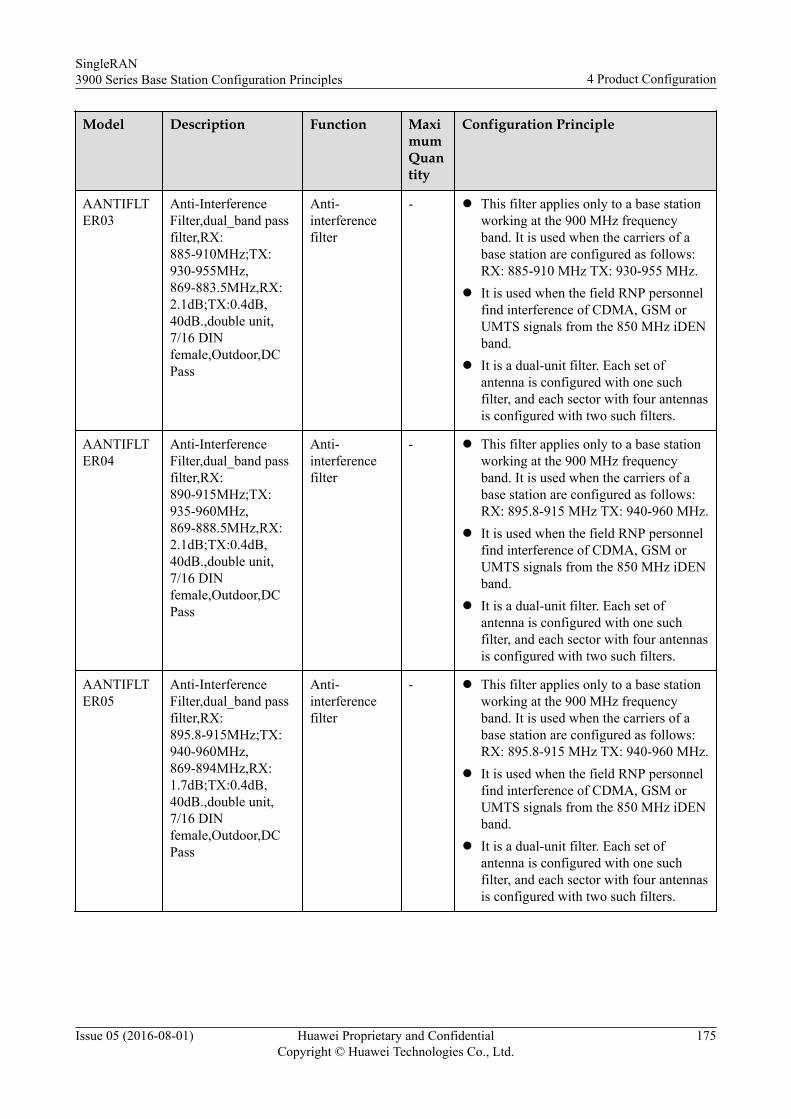
Model Description Function MaximumQuantity
Configuration Principle
AANTIFLTER03
Anti-InterferenceFilter,dual_band passfilter,RX:885-910MHz;TX:930-955MHz,869-883.5MHz,RX:2.1dB;TX:0.4dB,40dB.,double unit,7/16 DINfemale,Outdoor,DCPass
Anti-interferencefilter
- l This filter applies only to a base stationworking at the 900 MHz frequencyband. It is used when the carriers of abase station are configured as follows:RX: 885-910 MHz TX: 930-955 MHz.
l It is used when the field RNP personnelfind interference of CDMA, GSM orUMTS signals from the 850 MHz iDENband.
l It is a dual-unit filter. Each set ofantenna is configured with one suchfilter, and each sector with four antennasis configured with two such filters.
AANTIFLTER04
Anti-InterferenceFilter,dual_band passfilter,RX:890-915MHz;TX:935-960MHz,869-888.5MHz,RX:2.1dB;TX:0.4dB,40dB.,double unit,7/16 DINfemale,Outdoor,DCPass
Anti-interferencefilter
- l This filter applies only to a base stationworking at the 900 MHz frequencyband. It is used when the carriers of abase station are configured as follows:RX: 895.8-915 MHz TX: 940-960 MHz.
l It is used when the field RNP personnelfind interference of CDMA, GSM orUMTS signals from the 850 MHz iDENband.
l It is a dual-unit filter. Each set ofantenna is configured with one suchfilter, and each sector with four antennasis configured with two such filters.
AANTIFLTER05
Anti-InterferenceFilter,dual_band passfilter,RX:895.8-915MHz;TX:940-960MHz,869-894MHz,RX:1.7dB;TX:0.4dB,40dB.,double unit,7/16 DINfemale,Outdoor,DCPass
Anti-interferencefilter
- l This filter applies only to a base stationworking at the 900 MHz frequencyband. It is used when the carriers of abase station are configured as follows:RX: 895.8-915 MHz TX: 940-960 MHz.
l It is used when the field RNP personnelfind interference of CDMA, GSM orUMTS signals from the 850 MHz iDENband.
l It is a dual-unit filter. Each set ofantenna is configured with one suchfilter, and each sector with four antennasis configured with two such filters.
SingleRAN3900 Series Base Station Configuration Principles 4 Product Configuration
Issue 05 (2016-08-01) Huawei Proprietary and ConfidentialCopyright © Huawei Technologies Co., Ltd.
175
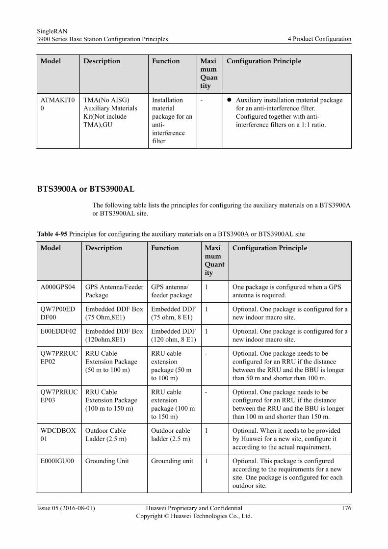
Model Description Function MaximumQuantity
Configuration Principle
ATMAKIT00
TMA(No AISG)Auxiliary MaterialsKit(Not includeTMA),GU
Installationmaterialpackage for ananti-interferencefilter
- l Auxiliary installation material packagefor an anti-interference filter.Configured together with anti-interference filters on a 1:1 ratio.
BTS3900A or BTS3900AL
The following table lists the principles for configuring the auxiliary materials on a BTS3900Aor BTS3900AL site.
Table 4-95 Principles for configuring the auxiliary materials on a BTS3900A or BTS3900AL site
Model Description Function MaximumQuantity
Configuration Principle
A000GPS04 GPS Antenna/FeederPackage
GPS antenna/feeder package
1 One package is configured when a GPSantenna is required.
QW7P00EDDF00
Embedded DDF Box(75 Ohm,8E1)
Embedded DDF(75 ohm, 8 E1)
1 Optional. One package is configured for anew indoor macro site.
E00EDDF02 Embedded DDF Box(120ohm,8E1)
Embedded DDF(120 ohm, 8 E1)
1 Optional. One package is configured for anew indoor macro site.
QW7PRRUCEP02
RRU CableExtension Package(50 m to 100 m)
RRU cableextensionpackage (50 mto 100 m)
- Optional. One package needs to beconfigured for an RRU if the distancebetween the RRU and the BBU is longerthan 50 m and shorter than 100 m.
QW7PRRUCEP03
RRU CableExtension Package(100 m to 150 m)
RRU cableextensionpackage (100 mto 150 m)
- Optional. One package needs to beconfigured for an RRU if the distancebetween the RRU and the BBU is longerthan 100 m and shorter than 150 m.
WDCDBOX01
Outdoor CableLadder (2.5 m)
Outdoor cableladder (2.5 m)
1 Optional. When it needs to be providedby Huawei for a new site, configure itaccording to the actual requirement.
E000IGU00 Grounding Unit Grounding unit 1 Optional. This package is configuredaccording to the requirements for a newsite. One package is configured for eachoutdoor site.
SingleRAN3900 Series Base Station Configuration Principles 4 Product Configuration
Issue 05 (2016-08-01) Huawei Proprietary and ConfidentialCopyright © Huawei Technologies Co., Ltd.
176
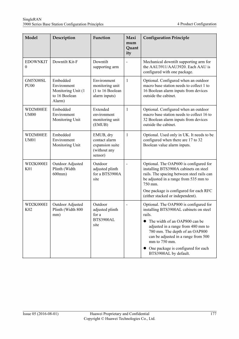
Model Description Function MaximumQuantity
Configuration Principle
EDOWNKIT0
Downtilt Kit-F Downtiltsupporting arm
- Mechanical downtilt supporting arm forthe AAU3911/AAU3920. Each AAU isconfigured with one package.
GM5X00SLPU00
EmbeddedEnvironmentMonitoring Unit (1to 16 BooleanAlarm)
Environmentmonitoring unit(1 to 16 Booleanalarm inputs)
1 Optional. Configured when an outdoormacro base station needs to collect 1 to16 Boolean alarm inputs from devicesoutside the cabinet.
WD2M00EEUM00
EmbeddedEnvironmentMonitoring Unit
Extendedenvironmentmonitoring unit(EMUB)
1 Optional. Configured when an outdoormacro base station needs to collect 16 to32 Boolean alarm inputs from devicesoutside the cabinet.
WD2M00EEUM01
EmbeddedEnvironmentMonitoring Unit
EMUB, drycontact alarmexpansion suite(without anysensor)
1 Optional. Used only in UK. It needs to beconfigured when there are 17 to 32Boolean value alarm inputs.
WD2K000EIK01
Outdoor AdjustedPlinth (Width600mm)
Outdooradjusted plinthfor a BTS3900Asite
- Optional. The OAP600 is configured forinstalling BTS3900A cabinets on steelrails. The spacing between steel rails canbe adjusted in a range from 535 mm to750 mm.One package is configured for each RFC(either stacked or independent).
WD2K000EIK02
Outdoor AdjustedPlinth (Width 800mm)
Outdooradjusted plinthfor aBTS3900ALsite
- Optional. The OAP800 is configured forinstalling BTS3900AL cabinets on steelrails.l The width of an OAP800 can be
adjusted in a range from 480 mm to780 mm. The depth of an OAP800can be adjusted in a range from 500mm to 750 mm.
l One package is configured for eachBTS3900AL by default.
SingleRAN3900 Series Base Station Configuration Principles 4 Product Configuration
Issue 05 (2016-08-01) Huawei Proprietary and ConfidentialCopyright © Huawei Technologies Co., Ltd.
177
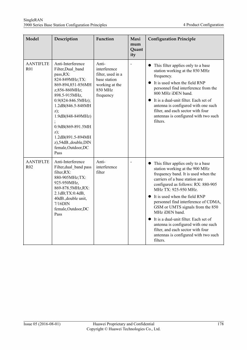
Model Description Function MaximumQuantity
Configuration Principle
AANTIFLTER01
Anti-InterferenceFilter,Dual_bandpass,RX:824-849MHz;TX:869-894,851-856MHz;856-860MHz;898.5-915MHz,0.9(824-846.5MHz);1.2dB(846.5-848MHz);1.9dB(848-849MHz);0.9dB(869-891.5MHz);1.2dB(891.5-894MHz),54dB.,double,DINfemale,Outdoor,DCPass
Anti-interferencefilter, used in abase stationworking at the850 MHzfrequency
- l This filter applies only to a basestation working at the 850 MHzfrequency.
l It is used when the field RNPpersonnel find interference from the800 MHz iDEN band.
l It is a dual-unit filter. Each set ofantenna is configured with one suchfilter, and each sector with fourantennas is configured with two suchfilters.
AANTIFLTER02
Anti-InterferenceFilter,dual_band passfilter,RX:880-905MHz;TX:925-950MHz,869-878.5MHz,RX:2.1dB;TX:0.4dB,40dB.,double unit,7/16DINfemale,Outdoor,DCPass
Anti-interferencefilter
- l This filter applies only to a basestation working at the 900 MHzfrequency band. It is used when thecarriers of a base station areconfigured as follows: RX: 880-905MHz TX: 925-950 MHz.
l It is used when the field RNPpersonnel find interference of CDMA,GSM or UMTS signals from the 850MHz iDEN band.
l It is a dual-unit filter. Each set ofantenna is configured with one suchfilter, and each sector with fourantennas is configured with two suchfilters.
SingleRAN3900 Series Base Station Configuration Principles 4 Product Configuration
Issue 05 (2016-08-01) Huawei Proprietary and ConfidentialCopyright © Huawei Technologies Co., Ltd.
178
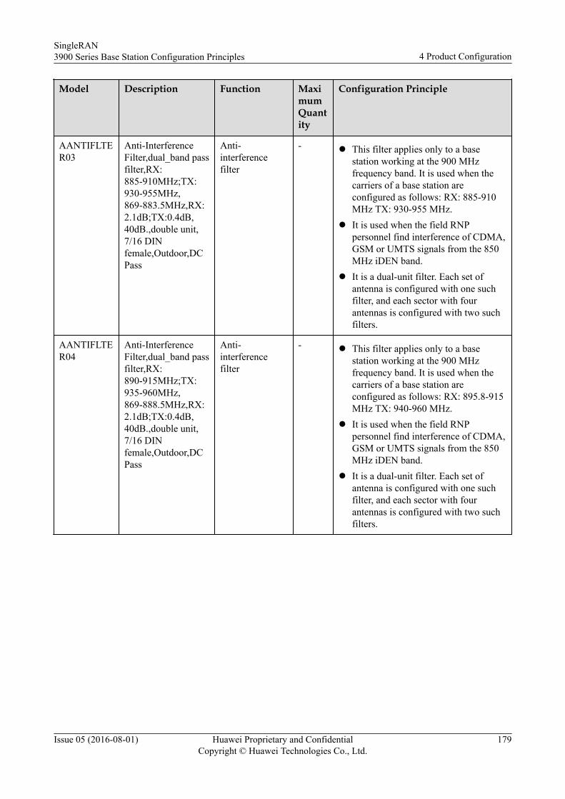
Model Description Function MaximumQuantity
Configuration Principle
AANTIFLTER03
Anti-InterferenceFilter,dual_band passfilter,RX:885-910MHz;TX:930-955MHz,869-883.5MHz,RX:2.1dB;TX:0.4dB,40dB.,double unit,7/16 DINfemale,Outdoor,DCPass
Anti-interferencefilter
- l This filter applies only to a basestation working at the 900 MHzfrequency band. It is used when thecarriers of a base station areconfigured as follows: RX: 885-910MHz TX: 930-955 MHz.
l It is used when the field RNPpersonnel find interference of CDMA,GSM or UMTS signals from the 850MHz iDEN band.
l It is a dual-unit filter. Each set ofantenna is configured with one suchfilter, and each sector with fourantennas is configured with two suchfilters.
AANTIFLTER04
Anti-InterferenceFilter,dual_band passfilter,RX:890-915MHz;TX:935-960MHz,869-888.5MHz,RX:2.1dB;TX:0.4dB,40dB.,double unit,7/16 DINfemale,Outdoor,DCPass
Anti-interferencefilter
- l This filter applies only to a basestation working at the 900 MHzfrequency band. It is used when thecarriers of a base station areconfigured as follows: RX: 895.8-915MHz TX: 940-960 MHz.
l It is used when the field RNPpersonnel find interference of CDMA,GSM or UMTS signals from the 850MHz iDEN band.
l It is a dual-unit filter. Each set ofantenna is configured with one suchfilter, and each sector with fourantennas is configured with two suchfilters.
SingleRAN3900 Series Base Station Configuration Principles 4 Product Configuration
Issue 05 (2016-08-01) Huawei Proprietary and ConfidentialCopyright © Huawei Technologies Co., Ltd.
179
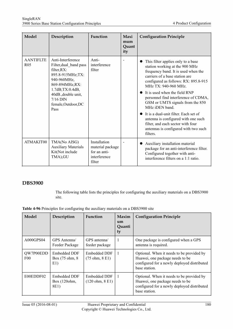
Model Description Function MaximumQuantity
Configuration Principle
AANTIFLTER05
Anti-InterferenceFilter,dual_band passfilter,RX:895.8-915MHz;TX:940-960MHz,869-894MHz,RX:1.7dB;TX:0.4dB,40dB.,double unit,7/16 DINfemale,Outdoor,DCPass
Anti-interferencefilter
- l This filter applies only to a basestation working at the 900 MHzfrequency band. It is used when thecarriers of a base station areconfigured as follows: RX: 895.8-915MHz TX: 940-960 MHz.
l It is used when the field RNPpersonnel find interference of CDMA,GSM or UMTS signals from the 850MHz iDEN band.
l It is a dual-unit filter. Each set ofantenna is configured with one suchfilter, and each sector with fourantennas is configured with two suchfilters.
ATMAKIT00 TMA(No AISG)Auxiliary MaterialsKit(Not includeTMA),GU
Installationmaterial packagefor an anti-interferencefilter
- l Auxiliary installation materialpackage for an anti-interference filter.Configured together with anti-interference filters on a 1:1 ratio.
DBS3900
The following table lists the principles for configuring the auxiliary materials on a DBS3900site.
Table 4-96 Principles for configuring the auxiliary materials on a DBS3900 site
Model Description Function MaximumQuantity
Configuration Principle
A000GPS04 GPS Antenna/Feeder Package
GPS antenna/feeder package
1 One package is configured when a GPSantenna is required.
QW7P00EDDF00
Embedded DDFBox (75 ohm, 8E1)
Embedded DDF(75 ohm, 8 E1)
1 Optional. When it needs to be provided byHuawei, one package needs to beconfigured for a newly deployed distributedbase station.
E00EDDF02 Embedded DDFBox (120ohm,8E1)
Embedded DDF(120 ohm, 8 E1)
1 Optional. When it needs to be provided byHuawei, one package needs to beconfigured for a newly deployed distributedbase station.
SingleRAN3900 Series Base Station Configuration Principles 4 Product Configuration
Issue 05 (2016-08-01) Huawei Proprietary and ConfidentialCopyright © Huawei Technologies Co., Ltd.
180
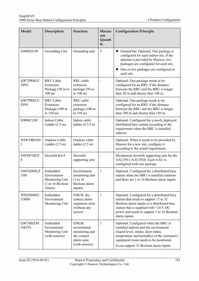
Model Description Function MaximumQuantity
Configuration Principle
E000IGU00 Grounding Unit Grounding unit 2 l Ground bar. Optional. One package isconfigured for each indoor site. If theantenna is provided by Huawei, twopackages are configured for each site.
l One or two packages are configured ateach site.
QW7PRRUCEP02
RRU CableExtensionPackage (50 m to100 m)
RRU cableextensionpackage (50 mto 100 m)
- Optional. One package needs to beconfigured for an RRU if the distancebetween the RRU and the BBU is longerthan 50 m and shorter than 100 m.
QW7PRRUCEP03
RRU CableExtensionPackage (100 mto 150 m)
RRU cableextensionpackage (100 mto 150 m)
- Optional. One package needs to beconfigured for an RRU if the distancebetween the RRU and the BBU is longerthan 100 m and shorter than 150 m.
E000ICL00 Indoor CableLadder (2.5 m)
Indoor cableladder of 2.5 m
- Optional. Configured for a newly deployeddistributed base station according to therequirement when the BBU is installedindoors.
WDCDBOX01
Outdoor CableLadder (2.5 m)
Outdoor cableladder (2.5 m)
- Optional. When it needs to be provided byHuawei for a new site, configure itaccording to the actual requirement.
EDOWNKIT0
Downtilt Kit-F Downtiltsupporting arm
- Mechanical downtilt supporting arm for theAAU3911/AAU3920. Each AAU isconfigured with one package.
GM5X00SLPU00
EmbeddedEnvironmentMonitoring Unit(1 to 16 BooleanAlarm)
Environmentmonitoring unit(1 to 16Boolean alarminputs)
1 Optional. Configured for a distributed basestation when the BBU is installed outdoorsand there are 1 to 16 Boolean alarm inputs.
WD2M00EEUM00
EmbeddedEnvironmentMonitoring Unit
EMUB, drycontact alarmexpansion suite(without anysensor)
1 Optional. Configured for a distributed basestation that needs to support 17 to 32Boolean alarm inputs or a distributed basestation that is supplied with +24 V DCpower and needs to support 1 to 16 Booleanalarm inputs.
QW7MEEMUKIT0
EmbeddedEnvironmentMonitoring Unit(with sensors)
EMUB,environmentmonitoring anddry contactalarm suite(with sensors)
1 Optional. Configured when the BBU isinstalled indoors and the environment(liquid level, smoke, door status,temperature and humidity) of the customer'sequipment room needs to be monitored.It can support 32 Boolean alarm inputs.
SingleRAN3900 Series Base Station Configuration Principles 4 Product Configuration
Issue 05 (2016-08-01) Huawei Proprietary and ConfidentialCopyright © Huawei Technologies Co., Ltd.
181
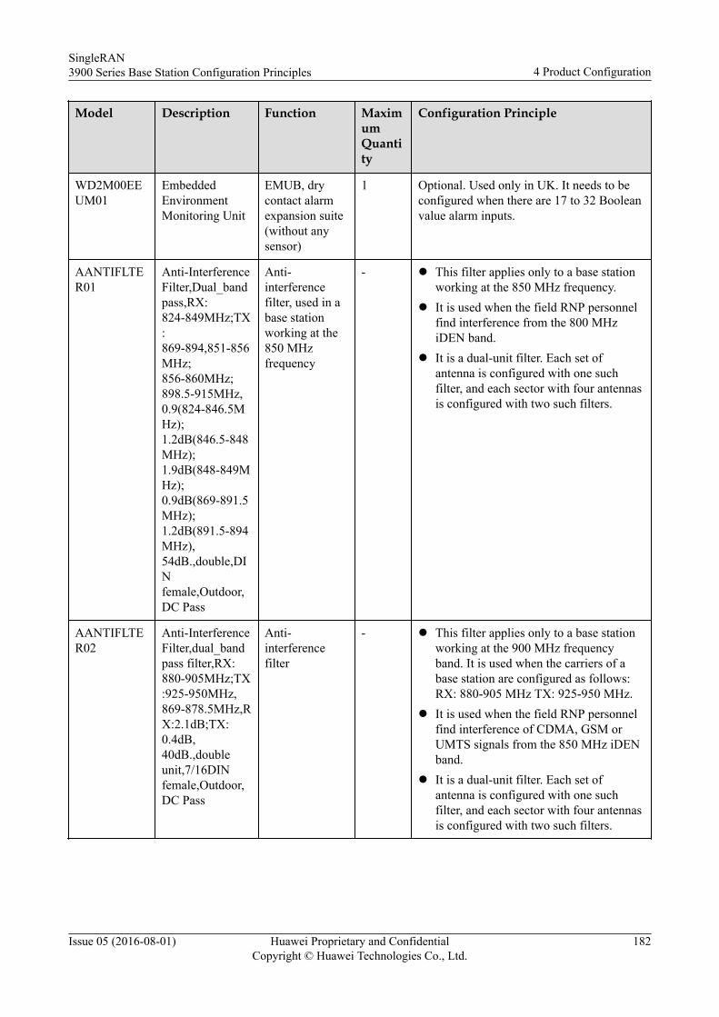
Model Description Function MaximumQuantity
Configuration Principle
WD2M00EEUM01
EmbeddedEnvironmentMonitoring Unit
EMUB, drycontact alarmexpansion suite(without anysensor)
1 Optional. Used only in UK. It needs to beconfigured when there are 17 to 32 Booleanvalue alarm inputs.
AANTIFLTER01
Anti-InterferenceFilter,Dual_bandpass,RX:824-849MHz;TX:869-894,851-856MHz;856-860MHz;898.5-915MHz,0.9(824-846.5MHz);1.2dB(846.5-848MHz);1.9dB(848-849MHz);0.9dB(869-891.5MHz);1.2dB(891.5-894MHz),54dB.,double,DINfemale,Outdoor,DC Pass
Anti-interferencefilter, used in abase stationworking at the850 MHzfrequency
- l This filter applies only to a base stationworking at the 850 MHz frequency.
l It is used when the field RNP personnelfind interference from the 800 MHziDEN band.
l It is a dual-unit filter. Each set ofantenna is configured with one suchfilter, and each sector with four antennasis configured with two such filters.
AANTIFLTER02
Anti-InterferenceFilter,dual_bandpass filter,RX:880-905MHz;TX:925-950MHz,869-878.5MHz,RX:2.1dB;TX:0.4dB,40dB.,doubleunit,7/16DINfemale,Outdoor,DC Pass
Anti-interferencefilter
- l This filter applies only to a base stationworking at the 900 MHz frequencyband. It is used when the carriers of abase station are configured as follows:RX: 880-905 MHz TX: 925-950 MHz.
l It is used when the field RNP personnelfind interference of CDMA, GSM orUMTS signals from the 850 MHz iDENband.
l It is a dual-unit filter. Each set ofantenna is configured with one suchfilter, and each sector with four antennasis configured with two such filters.
SingleRAN3900 Series Base Station Configuration Principles 4 Product Configuration
Issue 05 (2016-08-01) Huawei Proprietary and ConfidentialCopyright © Huawei Technologies Co., Ltd.
182
Model Description Function MaximumQuantity
Configuration Principle
AANTIFLTER03
Anti-InterferenceFilter,dual_bandpass filter,RX:885-910MHz;TX:930-955MHz,869-883.5MHz,RX:2.1dB;TX:0.4dB,40dB.,doubleunit,7/16 DINfemale,Outdoor,DC Pass
Anti-interferencefilter
- l This filter applies only to a base stationworking at the 900 MHz frequencyband. It is used when the carriers of abase station are configured as follows:RX: 885-910 MHz TX: 930-955 MHz.
l It is used when the field RNP personnelfind interference of CDMA, GSM orUMTS signals from the 850 MHz iDENband.
l It is a dual-unit filter. Each set ofantenna is configured with one suchfilter, and each sector with four antennasis configured with two such filters.
AANTIFLTER04
Anti-InterferenceFilter,dual_bandpass filter,RX:890-915MHz;TX:935-960MHz,869-888.5MHz,RX:2.1dB;TX:0.4dB,40dB.,doubleunit,7/16 DINfemale,Outdoor,DC Pass
Anti-interferencefilter
- l This filter applies only to a base stationworking at the 900 MHz frequencyband. It is used when the carriers of abase station are configured as follows:RX: 895.8-915 MHz TX: 940-960 MHz.
l It is used when the field RNP personnelfind interference of CDMA, GSM orUMTS signals from the 850 MHz iDENband.
l It is a dual-unit filter. Each set ofantenna is configured with one suchfilter, and each sector with four antennasis configured with two such filters.
AANTIFLTER05
Anti-InterferenceFilter,dual_bandpass filter,RX:895.8-915MHz;TX:940-960MHz,869-894MHz,RX:1.7dB;TX:0.4dB,40dB.,doubleunit,7/16 DINfemale,Outdoor,DC Pass
Anti-interferencefilter
- l This filter applies only to a base stationworking at the 900 MHz frequencyband. It is used when the carriers of abase station are configured as follows:RX: 895.8-915 MHz TX: 940-960 MHz.
l It is used when the field RNP personnelfind interference of CDMA, GSM orUMTS signals from the 850 MHz iDENband.
l It is a dual-unit filter. Each set ofantenna is configured with one suchfilter, and each sector with four antennasis configured with two such filters.
SingleRAN3900 Series Base Station Configuration Principles 4 Product Configuration
Issue 05 (2016-08-01) Huawei Proprietary and ConfidentialCopyright © Huawei Technologies Co., Ltd.
183
Model Description Function MaximumQuantity
Configuration Principle
ATMAKIT00 TMA(No AISG)AuxiliaryMaterialsKit(Not includeTMA),GU
Installationmaterialpackage for ananti-interferencefilter
- l Auxiliary installation material packagefor an anti-interference filter. Configuredtogether with anti-interference filters ona 1:1 ratio.
BTS3900CThe following table lists the principles for configuring the auxiliary materials on a BTS3900Csite.
Table 4-97 Auxiliary materials for a BTS3900C site
Model Description Function MaximumQuantity
Configuration Principle
E000IGU00 GroundingUnit
Grounding unit 1 Optional. This package is configuredaccording to the requirements for a newsite. One package is configured for eachoutdoor site.
A000GPS04 GPS Antenna/FeederPackage
GPS antenna/feederpackage
1 One package is configured when a GPSantenna is required.
SingleRAN3900 Series Base Station Configuration Principles 4 Product Configuration
Issue 05 (2016-08-01) Huawei Proprietary and ConfidentialCopyright © Huawei Technologies Co., Ltd.
184
5 Typical Configurations and Capacity
Expansion
This section describes the typical configuration scenarios and capacity expansion scenarios of3900 series base stations.
5.1 Typical Configurations
5.2 Capacity Expansion Principles
SingleRAN3900 Series Base Station Configuration Principles 5 Typical Configurations and Capacity Expansion
Issue 05 (2016-08-01) Huawei Proprietary and ConfidentialCopyright © Huawei Technologies Co., Ltd.
185
5.1 Typical ConfigurationsThis section describes the typical configurations of a 3900 series base station in variousapplication scenarios.
5.1.1 Single ModeThis section describes the typical configurations of a 3900 series base station working inGSM, UMTS, or LTE mode and using RRUs.
Typical Configuration of a GSM Base Station
The following describes typical configuration of a base station working in GSM 900 MHzS4/4/4 mode.
Table 5-1 Typical configuration of a GSM base station
Product Configuration Quantity
BBU 1
GTMUc 1
RRU 3
GSM Multiple Transceiver for Multi-Mode Module 3
GSM Multiple Transceiver for the 2nd TRX of Multi-Mode Module
6
Typical Configuration of a UMTS Base Station
The following describes typical configurations in scenarios of S2/2/2 non-MIMO andS2/2/2/2/2/2 non-MIMO.
NOTE
When MIMO is not used, each carrier provides output power of 20 W.
Table 5-2 Typical configuration of a UMTS base station
Product Configuration Quantity (S2/2/2 Non-MIMO)
Quantity (S2/2/2/2/2/2 Non-MIMO)
BBU 1 1
UMPTb1 1 1
UBBPd4 1 2
RRU 3 6
Multi Carrier License (per Carrier) 3 6
SingleRAN3900 Series Base Station Configuration Principles 5 Typical Configurations and Capacity Expansion
Issue 05 (2016-08-01) Huawei Proprietary and ConfidentialCopyright © Huawei Technologies Co., Ltd.
186
Product Configuration Quantity (S2/2/2 Non-MIMO)
Quantity (S2/2/2/2/2/2 Non-MIMO)
Power License (per 20W) 3 6
UBBP First-Mode license (UMTS) (perUBBP)
1 2
Typical Configuration of an LTE Base StationThe following describes typical configurations in scenarios of S1/1/1 20 MHz (DL 2x2MIMO) and S1/1/1 20 MHz (DL 4x4 MIMO).
NOTE
This section assumes that each channel provides 20 W power.
Table 5-3 Typical configurations of an LTE base station using the RRU3201
Product Configuration Quantity (S1/1/1 20 MHz[DL 2x2 MIMO])
Quantity (S1/1/1 20 MHz[DL 4x4 MIMO])
BBU 1 1
UMPTb1 1 1
UBBPd6 1 1
RRU (2T2R) 3 6
RF Output Power (per 20W) 3 6
Carrier Bandwidth - 0 MHz to 5 MHz 3 3
Carrier Bandwidth - 5 MHz to 10 MHz 3 3
Carrier Bandwidth - 10 MHz to 15 MHz 3 3
Carrier Bandwidth - 15 MHz to 20 MHz 3 3
Resource Block (per RB) 150 150
5.1.2 GU Dual ModeThis section describes the typical configurations of a 3900 series base station working in themode of GSM 900 MHz S4/4/4+UMTS 900 MHz S2/2/2 (non-MIMO).
NOTE
Each UMTS carrier supports 20 W power.
SingleRAN3900 Series Base Station Configuration Principles 5 Typical Configurations and Capacity Expansion
Issue 05 (2016-08-01) Huawei Proprietary and ConfidentialCopyright © Huawei Technologies Co., Ltd.
187
Table 5-4 Typical configurations of a base station using GU SDR modules and working in the mode of GSM 900MHz S4/4/4+UMTS 900 MHz S2/2/2 (non-MIMO)
Product Configuration Quantity
BBU 1
UMPTb1 1
UBBPd4 1
RRU(GU SDR) 3
GSM/UMTS Dual Mode license (per sector) 3
GSM Multiple Transceiver for the 2nd TRX of Multi-Mode Module
6
GSM Multiple Transceiver for Multi-Mode Module 6
UMTS Multi Carrier License for the 1st Carrier ofMulti-Mode (per Carrier)
3
UMTS Multi Carrier License for Multi-Mode Module(per Carrier)
3
RF Output Power (per 20W) 3
UBBP First-Mode license (UMTS) (per UBBP) 1
UMPT Multi Mode license(UMTS) (per UMPT) 1
5.1.3 GL Dual ModeThis section describes the typical configurations of a 3900 series base station working in themode of GSM 1800 MHz S4/4/4+LTE 1800 MHz S1/1/1 20 MHz (2x2 MIMO).
NOTE
l The following configurations assume that each LTE channel provides 20 W transmit power.
l The following configurations assume that each GSM carrier provides 20 W transmit power.
Table 5-5 Typical configurations of a base station working in the mode of GSM 1800 MHz S4/4/4+LTE 1800MHz S1/1/1 20 MHz (2x2 MIMO)
Product Configuration Quantity
BBU 1
UMPTb1 1
UBBPd6 1
RRU(GL SDR) 3
RF Output Power (per 20 W) 3
SingleRAN3900 Series Base Station Configuration Principles 5 Typical Configurations and Capacity Expansion
Issue 05 (2016-08-01) Huawei Proprietary and ConfidentialCopyright © Huawei Technologies Co., Ltd.
188
Product Configuration Quantity
Carrier Bandwidth - 0 MHz to 5 MHz 3
Carrier Bandwidth - 5 MHz to 10 MHz 3
Carrier Bandwidth - 10 MHz to 15 MHz 3
Carrier Bandwidth - 15 MHz to 20 MHz 3
GSM/UMTS Dual Mode license (per sector) 3
GSM Multiple Transceiver for the 2nd TRX of Multi-ModeModule
6
Resource Block (per RB) 150
UMPT Multi Mode license(LTE FDD) (per UMPT) 1
UBBP First-Mode license (LTE FDD) (per UBBP) 1
GSM/LTE Dual Mode license (per Sector) 3
5.1.4 UL Dual ModeThis section describes the typical configurations of a 3900 series base station working in themode of UMTS 2100 MHz S2/2/2 (non-MIMO)+LTE 2100 MHz S1/1/1 20 MHz (2x2MIMO).
NOTE
The following configurations assume that each LTE channel provides 20 W transmit power.
The following configurations assume that each UMTS carrier provides 20 W transmit power.
Table 5-6 Typical configurations in a UL scenario of UMTS 2100 MHz S2/2/2 (non-MIMO)+LTE 2100 MHzS1/1/1 20 MHz (2x2 MIMO)
Product Configuration Quantity
BBU 1
UMPTb1 1
UBBPd6 1
RRU (UL SDR) 3
UMTS/LTE Dual Mode license (per sector) 3
UMTS Multi Carrier License for the 1st Carrier of Multi-Mode Module (per Carrier)
3
UMTS Multi Carrier License for Multi-Mode Module (perCarrier)
3
SingleRAN3900 Series Base Station Configuration Principles 5 Typical Configurations and Capacity Expansion
Issue 05 (2016-08-01) Huawei Proprietary and ConfidentialCopyright © Huawei Technologies Co., Ltd.
189
Product Configuration Quantity
Power License (per 20 W) 3
UBBP First-Mode license (UMTS) (Per UBBP) 1
UBBP Multi-Mode license (LTE FDD) (per UBBP) 1
Carrier Bandwidth - 0 MHz to 5 MHz 3
Carrier Bandwidth - 5 MHz to 10 MHz 3
Carrier Bandwidth - 10 MHz to 15 MHz 0
Carrier Bandwidth - 15 MHz to 20 MHz 0
Resource Block 150
UMPT Multi Mode license (LTE FDD) (per UMPT) 1
5.1.5 GUL Triple ModesThis section describes the typical configurations of a 3900 series base station working in triplemodes.
NOTE
l For the non-MIMO configuration of UMTS, each carrier provides 20 W output power. For MIMOconfiguration of UMTS, each carrier provides 40 W (2x20 W) output power.
l The following configurations assume that each LTE channel provides 20 W transmit power.
The following table describes the typical configurations of a base station working in the modeof GSM 900 MHz S2/2/2+UMTS 900 MHz S2/2/2 (non-MIMO)+LTE 2600 MHz S1/1/1 10MHz (DL 2x2 MIMO).
Table 5-7 Typical configurations of a base station in which GU SDR modules are used and GU and LTE aredeployed on two BBUs
Product Configuration Quantity
BBU 2
GTMU 1
UMPTb1 2
UBBPd4 1
UBBPd6 1
RRU (GU SDR) 3
RRU (LO) 3
GSM/UMTS Dual Mode license (per sector) 3
SingleRAN3900 Series Base Station Configuration Principles 5 Typical Configurations and Capacity Expansion
Issue 05 (2016-08-01) Huawei Proprietary and ConfidentialCopyright © Huawei Technologies Co., Ltd.
190
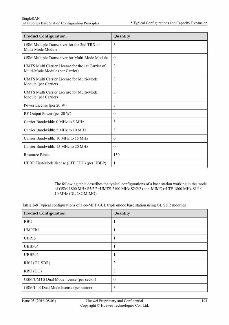
Product Configuration Quantity
GSM Multiple Transceiver for the 2nd TRX ofMulti-Mode Module
3
GSM Multiple Transceiver for Multi-Mode Module 0
UMTS Multi Carrier License for the 1st Carrier ofMulti-Mode Module (per Carrier)
3
UMTS Multi Carrier License for Multi-ModeModule (per Carrier)
3
UMTS Multi Carrier License for Multi-ModeModule (per Carrier)
3
Power License (per 20 W) 3
RF Output Power (per 20 W) 0
Carrier Bandwidth: 0 MHz to 5 MHz 3
Carrier Bandwidth: 5 MHz to 10 MHz 3
Carrier Bandwidth: 10 MHz to 15 MHz 0
Carrier Bandwidth: 15 MHz to 20 MHz 0
Resource Block 150
UBBP First-Mode license (LTE FDD) (per UBBP) 1
The following table describes the typical configurations of a base station working in the modeof GSM 1800 MHz S3/3/3+UMTS 2100 MHz S2/2/2 (non-MIMO)+LTE 1800 MHz S1/1/110 MHz (DL 2x2 MIMO).
Table 5-8 Typical configurations of a co-MPT GUL triple-mode base station using GL SDR modules
Product Configuration Quantity
BBU 1
UMPTb1 1
UBRIb 1
UBBPd4 1
UBBPd6 1
RRU (GL SDR) 3
RRU (UO) 3
GSM/UMTS Dual Mode license (per sector) 0
GSM/LTE Dual Mode license (per sector) 3
SingleRAN3900 Series Base Station Configuration Principles 5 Typical Configurations and Capacity Expansion
Issue 05 (2016-08-01) Huawei Proprietary and ConfidentialCopyright © Huawei Technologies Co., Ltd.
191
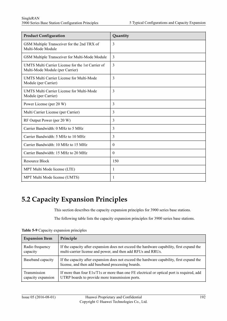
Product Configuration Quantity
GSM Multiple Transceiver for the 2nd TRX ofMulti-Mode Module
3
GSM Multiple Transceiver for Multi-Mode Module 3
UMTS Multi Carrier License for the 1st Carrier ofMulti-Mode Module (per Carrier)
3
UMTS Multi Carrier License for Multi-ModeModule (per Carrier)
3
UMTS Multi Carrier License for Multi-ModeModule (per Carrier)
3
Power License (per 20 W) 3
Multi Carrier License (per Carrier) 3
RF Output Power (per 20 W) 3
Carrier Bandwidth: 0 MHz to 5 MHz 3
Carrier Bandwidth: 5 MHz to 10 MHz 3
Carrier Bandwidth: 10 MHz to 15 MHz 0
Carrier Bandwidth: 15 MHz to 20 MHz 0
Resource Block 150
MPT Multi Mode license (LTE) 1
MPT Multi Mode license (UMTS) 1
5.2 Capacity Expansion PrinciplesThis section describes the capacity expansion principles for 3900 series base stations.
The following table lists the capacity expansion principles for 3900 series base stations.
Table 5-9 Capacity expansion principles
Expansion Item Principle
Radio frequencycapacity
If the capacity after expansion does not exceed the hardware capability, first expand themulti-carrier license and power, and then add RFUs and RRUs.
Baseband capacity If the capacity after expansion does not exceed the hardware capability, first expand thelicense, and then add baseband processing boards.
Transmissioncapacity expansion
If more than four E1s/T1s or more than one FE electrical or optical port is required, addUTRP boards to provide more transmission ports.
SingleRAN3900 Series Base Station Configuration Principles 5 Typical Configurations and Capacity Expansion
Issue 05 (2016-08-01) Huawei Proprietary and ConfidentialCopyright © Huawei Technologies Co., Ltd.
192
NOTE
For the typical configurations after capacity expansion, see 5.1 Typical Configurations.
SingleRAN3900 Series Base Station Configuration Principles 5 Typical Configurations and Capacity Expansion
Issue 05 (2016-08-01) Huawei Proprietary and ConfidentialCopyright © Huawei Technologies Co., Ltd.
193