Embed Size (px)
Citation preview
7/16/2019 3900 Manual
http://slidepdf.com/reader/full/3900-manual 1/266
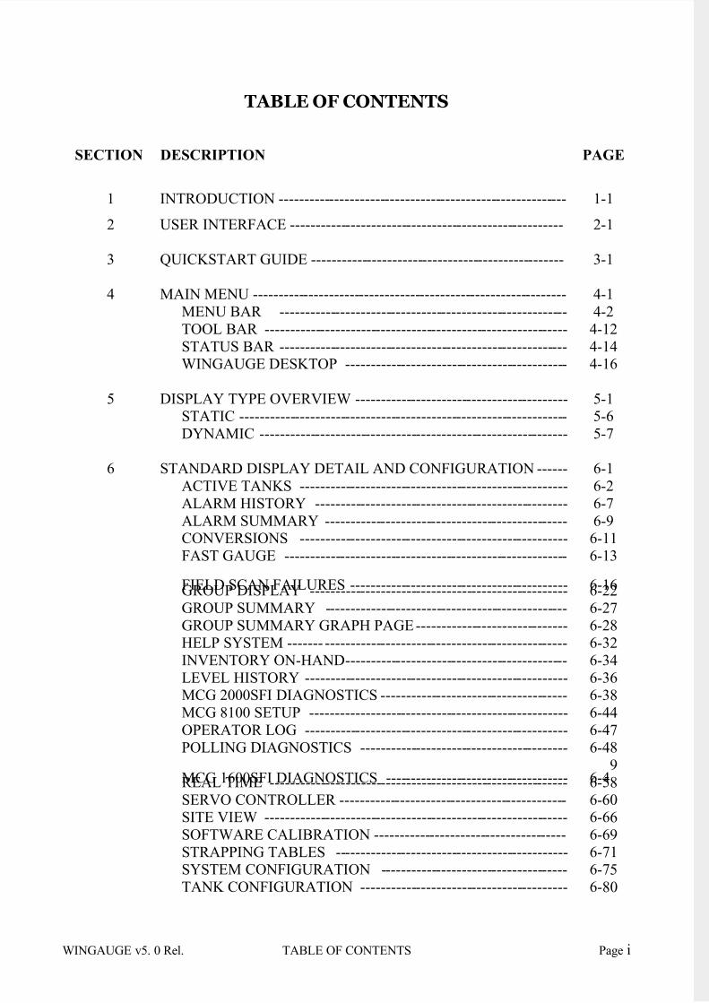
WINGAUGE v5. 0 Rel. TABLE OF CONTENTS Page i
TABLE OF CONTENTS
SECTION DESCRIPTION PAGE
1 INTRODUCTION --------------------------------------------------------- 1-1
2 USER INTERFACE ------------------------------------------------------ 2-1
3 QUICKSTART GUIDE -------------------------------------------------- 3-1
4 MAIN MENU -------------------------------------------------------------- 4-1
MENU BAR --------------------------------------------------------- 4-2
TOOL BAR ------------------------------------------------------------ 4-12
STATUS BAR --------------------------------------------------------- 4-14WINGAUGE DESKTOP -------------------------------------------- 4-16
5 DISPLAY TYPE OVERVIEW ------------------------------------------ 5-1STATIC ----------------------------------------------------------------- 5-6
DYNAMIC ------------------------------------------------------------- 5-7
6 STANDARD DISPLAY DETAIL AND CONFIGURATION ------ 6-1
ACTIVE TANKS ----------------------------------------------------- 6-2
ALARM HISTORY -------------------------------------------------- 6-7
ALARM SUMMARY ------------------------------------------------ 6-9CONVERSIONS ----------------------------------------------------- 6-11
FAST GAUGE -------------------------------------------------------- 6-13
FIELD SCAN FAILURES ------------------------------------------- 6-16GROUP DISPLAY --------------------------------------------------- 6-22
GROUP SUMMARY ------------------------------------------------ 6-27
GROUP SUMMARY GRAPH PAGE ------------------------------ 6-28 HELP SYSTEM ------- ------------------------------------------------ 6-32
INVENTORY ON-HAND -------------------------------------------- 6-34
LEVEL HISTORY ---------------------------------------------------- 6-36 MCG 2000SFI DIAGNOSTICS ------------------------------------- 6-38
MCG 8100 SETUP --------------------------------------------------- 6-44
OPERATOR LOG ---------------------------------------------------- 6-47
POLLING DIAGNOSTICS ----------------------------------------- 6-48
MCG 1600SFI DIAGNOSTICS ------------------------------------ 6-49 REAL TIME ----------------------------------------------------------- 6-58
SERVO CONTROLLER --------------------------------------------- 6-60 SITE VIEW ------------------------------------------------------------ 6-66
SOFTWARE CALIBRATION -------------------------------------- 6-69
STRAPPING TABLES ---------------------------------------------- 6-71 SYSTEM CONFIGURATION ------------------------------------- 6-75
TANK CONFIGURATION ----------------------------------------- 6-80
7/16/2019 3900 Manual
http://slidepdf.com/reader/full/3900-manual 2/266
Page ii TABLE OF CONTENTS WINGAUGE v5.0 Rel.
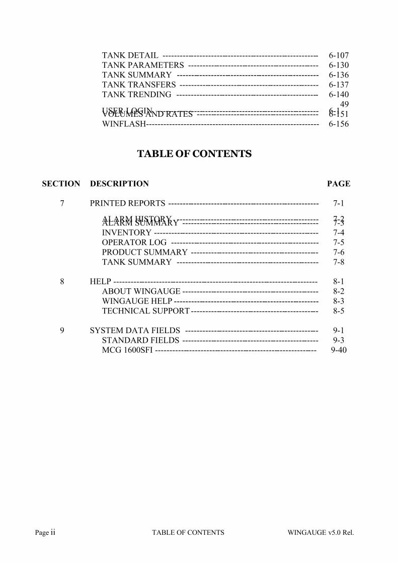
TANK DETAIL ------------------------------------------------------- 6-107
TANK PARAMETERS ---------------------------------------------- 6-130 TANK SUMMARY -------------------------------------------------- 6-136
TANK TRANSFERS ------------------------------------------------- 6-137
TANK TRENDING -------------------------------------------------- 6-140
USER LOGIN --------------------------------------------------------- 6-149
VOLUMES AND RATES ------------------------------------------- 6-151
WINFLASH------------------------------------------------------------ 6-156
TABLE OF CONTENTS
SECTION DESCRIPTION PAGE
7 PRINTED REPORTS ----------------------------------------------------- 7-1
ALARM HISTORY -------------------------------------------------- 7-2ALARM SUMMARY ------------------------------------------------ 7-3INVENTORY ---------------------------------------------------------- 7-4
OPERATOR LOG ---------------------------------------------------- 7-5
PRODUCT SUMMARY --------------------------------------------- 7-6
TANK SUMMARY -------------------------------------------------- 7-8
8 HELP ------------------------------------------------------------------------ 8-1
ABOUT WINGAUGE ------------------------------------------------ 8-2
WINGAUGE HELP --------------------------------------------------- 8-3
TECHNICAL SUPPORT --------------------------------------------- 8-5
9 SYSTEM DATA FIELDS ----------------------------------------------- 9-1
STANDARD FIELDS ------------------------------------------------ 9-3MCG 1600SFI --------------------------------------------------------- 9-40

7/16/2019 3900 Manual
http://slidepdf.com/reader/full/3900-manual 3/266
WINGAUGE v5.0 Rel. SECTION 1 – INTRODUCTION PAGE 1 –1
SECTION 1
7/16/2019 3900 Manual
http://slidepdf.com/reader/full/3900-manual 4/266
PAGE 1 – 2 SECTION 1 - INTRODUCTION WINGAUGE v5.0 Rel.
INTRODUCTION
This is the WINGauge Help System and On-Line Manual. Users of this manual will see aTopic Menu to the left. Click on any item in the list to view the corresponding Help file.
Users reading the printed copy should refer to the Using the Printed Manual section below.
The MCG3900 WINGauge is a sophisticated tank inventory managementsystem, capable of acquiring, processing and displaying real-time data from up toone thousand gauges. Gauge hardware from most of the major equipmentvendors is supported, and the software generates a variety of printed status,summary and inventory reports.
This Help System is written from an operations perspective, and is intended tohelp users learn to use the system to their best advantage. For detailed
information on installing and configuring WINGauge, the reader is referred to the Administrator’s Guide.
Using the Help System and On-line Manual - Operators using the system on-line can access information and details on specific display pages by clicking onthe topic or display name to the left of this manual page. The information on eachpage is intended to inform the operator on how to read, modify and configureeach page to meet their requirements. Details should be available for modifyingany configurable parameters on each page. The individual pages are set-up toshow:
• the menu bar and method of opening the page at the top
• a sample display of the page
• a description of the display and its purpose
• any configurable items on that page
• the security level normally required for changing that item.
This manual is broken in to topics (shown at left) with any sub-sections indentedfor easy reference. The following is a list of the major topics in order:
• Introduction - This section gives an introduction to the Wingauge system
as well as information on using the On-line manual and printed manualorganization.
• User Interface - Overview of the MCG3900 graphical user interface..
• Quickstart Guide - How to enter basic configuration information..
7/16/2019 3900 Manual
http://slidepdf.com/reader/full/3900-manual 5/266
WINGAUGE v5.0 Rel. SECTION 1 – INTRODUCTION PAGE 1 –3
• Menu Bar - How to use the Menu Bar and access the various datadisplays..
• Tool Bar - How to use the Tool Bar.
• Status Bar - How to interpret information presented by the Status Bar.
• Display Types - Describes the different types and styles of displays..
• Standard Displays - Contains descriptions and detailed usageinstructions for the standard displays included with all WINGauge V5systems.
• Printed Reports - contains examples of the various hardcopy reports thesystem can generate.
• About WINGauge - How to access the WINGauge "About"/copyrightdisplay, and the system start uplog.
• Help System - How to use the Help System.
• Tech Support - Contact information for L&J Technical Support.
• Data Fields - Reference list of ALL data fields supported by WINGauge.
Using the Hard Copy Version of the Manual - Users of the MCG 3900Wingauge System can read details on specific display pages by finding the topicor display name in the table of contents to this manual page. The information oneach page is intended to inform the operator on how to read, modify andconfigure each page to meet their requirements. Details should be available for
modifying any configurable parameters on each page. The individual pages areset-up in a standard format to show:
• the menu bar and method of opening the page at the top
• a sample display of the page
• a description of the display and its purpose
• any configurable items on that page
• the security level normally required for changing that item.
The primary sections of this manual are shown below with a brief description of what is contained. The following items should appear:
• Introduction - This section. Gives an introduction to the Wingaugesystem as well as information on using the On-line manual and printedmanual organization.
7/16/2019 3900 Manual
http://slidepdf.com/reader/full/3900-manual 6/266
PAGE 1 – 4 SECTION 1 - INTRODUCTION WINGAUGE v5.0 Rel.
• System Operation - details the minimum required configuration for thesystem to function correctly.
• Main Menu Details - gives information on the layout of the Menu bar, Toolbar and Status bar. This section also gives general overviews of everymenu item and display type. This is a good place to start but after narrowing your search down to a specific display or topic, move to theStandard Display Details and Configuration section for more detailedinformation.
• Display Types Overview- gives a description of how to view or operatethe "static" and "dynamic" display pages.
• Standard Display Details and Configuration - Contains pages listed in Alphabetic order. Gives specific information on how to read, modify andconfigure each page. This is the section containing the most informationabout each display page.
• Printed Reports - contains examples of printed reports and details onhow to print them.
• Help - shows information contained in the items of the help menu.
As always, technical support is also available from L&J Technologies. If you can'tfind something or just can't figure it out, contact us at L&J Technologies. Phone708-236-6000.
What's new in Wingauge version 5.0 -This release, Version 5, introduces manynew features and functions. The following describes some of the more advanced
capabilities of the product.
DYNAMIC FORM GENERATOR
Significant enhancements have been made in the area of customizability: in fact,Version 5 is so flexible that administrators can modify existing displays or evencreate entirely new ones. Consequently, operations personnel are no longer required to simply accept the way their gauging system presents information andcan fine-tune it to suit individual requirements. Multiple monitor support is alsoavailable under the Windows 2000 Professional and Windows XP Professionaloperating systems with appropriate display hardware.
DYNAMIC REPORT GENERATOR
The technology behind the Dynamic Forms Generator has been applied toproducing quality printed reports. WINGauge supports dozens of unique datafields: any of these can be used to quickly and painlessly produce professionalprinted reports. Detail lines can be selected based upon specific criteria,optionally sorted by the contents of any field, and selectable totalization lines canbe inserted. The customer's corporate logo (or any other .BMP image file) can be
7/16/2019 3900 Manual
http://slidepdf.com/reader/full/3900-manual 7/266
WINGAUGE v5.0 Rel. SECTION 1 – INTRODUCTION PAGE 1 –5
included in the header of any report. Reports can optionally be printed in either Landscape or Portrait modes.
PLUG-IN TECHNOLOGY
A WINGauge plug-in is an external program module that can be "plugged in" at
any time. Existing installations benefit from being able to add functionality withoutotherwise modifying a working system. Systems that have unique requirementswill have new capabilities added as plug-ins: this has the effect of isolating anysite-specific functions from the standard offering. Plugin technology allowscustomers to painlessly upgrade their WINGauge operating software as newreleases are made available, while maintaining any custom features that weredeveloped for individual sites.
ADVANCED GAUGING MODULE
The Advanced Gauging Module (AGM), an integral part of the WINGaugesystem, provides a multi-loop, multi-protocol interface to field equipment. As tankfarms commonly have level gauges from different vendors, the AGM supportsover twenty different communications protocols. The AGM is capable of gaugingwith any or all of them simultaneously on up to thirty-two loops. Loop, interfaceand poll timing parameters are completely configurable by the systemadministrator. Custom protocol drivers can be developed to accommodate non-standard gauges, and can even be added to an existing Version 5 system withWINGauge’s plug-in technology.
AUTOMATIC ARCHIVER
For sites which require efficient access to historical tank data, the new
ARCHIVER feature generates a continuously-updated Microsoft Access-compatible database of real-time information. The frequency of updates, and thespecific data fields to be stored, are completely configurable by the user. Theinternal Tank Trending and Level History displays use this database, and this fileis accessible to the end user.
OPC SERVER
WINGauge now includes a server module for applications which require OPC(Open Process Control) 2.x connectivity. The user has complete control over theactual WINGauge data items which will be made available via OPC. Informationis posted on a tank-by-tank basis for easy access.
PERFORMANCE METRICS
The system monitors its' own real-time performance. Field loop scan times aswell as individual gauge polling rates and error counts are conveniently available.
7/16/2019 3900 Manual
http://slidepdf.com/reader/full/3900-manual 8/266
PAGE 1 – 6 SECTION 1 - INTRODUCTION WINGAUGE v5.0 Rel.
TANK TRANSFER
MONITORING
Tank Transfers may be monitored in real-time by the MCG3900. Transfers may
be initiated at any time, and can be programmed to terminate on volumetransferred, actual volume, ending time or total running time, or any combinationof the above. SCADA-style Valve and Pump control based upon transfer activitycan be implemented using the standard L&J control modules. Running gauges(i.e. simultaneous transfers from two or more tanks to or from a single tank) arenot currently supported.
AUTOMATIC CONFIGURATION
IMPORT
Remote control of WINGauge's internal functions and data structures can be
implemented via the Automatic Configuration Importer. This feature will monitor aspecified path for a standard text file containing a list of field descriptors and anddata items, and will automatically validate and import this information whenever the file is created or modified. Any data field which can be displayed using theDynamic Form Generator may be modified with the Importer.
SITEVIEW EDITOR
A standard feature of the WINGauge system is the SiteView graphical tank-farmdisplay. This popular display shows real-time gauging data superimposed uponan aerial, satellite or CAD view of a facility. Until now, a SiteView installation
could only be configured at the factory. That limitation has been removed, as thenew SiteView Editor allows authorized personnel to easily create detailedSiteViews from standard .BMP, .JPG or .TIF image files.
FASTGAUGE DISPLAY
The new FastGauge display allows selected tanks to be polled at a higher rate.FastGauge is very useful for more precisely resolving levels and volumes intanks which are in motion, particularly at facilities with smaller tanks or high flowrates.
HISTORICALDISPLAYS
The Trending and Level History displays have been completely rewritten. TheTrending display now uses the Access-compatible database generated by the
Archiver, and allows the user to selectively graph any or all of the numeric dataitems stored in the database. Likewise, the Level History display creates atabular view of this same information, organized by day and by hour.
7/16/2019 3900 Manual
http://slidepdf.com/reader/full/3900-manual 9/266
WINGAUGE v5.0 Rel. SECTION 1 – INTRODUCTION PAGE 1 –7
VERSATILE RATE CALCULATION
The new rate calculation module includes a sophisticated filtering algorithm toreduce the number and frequency of flow rate transients, and also has the abilityto handle extremely slow-moving or infrequently-polled tanks.
ADVANCED NETWORK MODULE
The Advanced Network Module performs several vital functions when runningWINGauge in a networked environment. It permits MCG3900 client systems toaccess live and archival data on a WINGauge server. Furthermore, this moduleallows multiple gauging servers to be linked together via a TCP/IP network toprovide a combined view of field data (Multi-field Integrated Gauging.) Thismodule also has support for fault-tolerant installations running a hot backup withan automatic switchover unit.
REAL-TIME CONNECTIVITY
Data acquired from live gauges may be exported in real-time. Data records maybe output in a variety of formats, including (but not limited to) XML, Microsoft
Access, or even comma-delimited text. Data may be transmitted via serial andnetwork links using popular protocols such as Modbus, TopTech and ProfiBus.Non-standard data interchange formats are accommodated via customWINGauge plug-in modules.
IMPROVED FIELD INTERFACE SUPPORT
The new Version 5 plug-in package has support for a number of new hardwareitems, and improved support for some existing products. The MCG1090
Magnetostrictive Level Probe, the MCG8140 Radio Level Probe, the MCG3221Modbus Interface, the MCG4200DO Relay Panel, the MCG4200AI Analog InputBoard and many more are now fully supported by the WINGauge InventoryManagement System.
MCG1500XL and MCG1500SFI SERVOS
The entire MCG1500XXX Servo Gauge product line is now supported byWINGauge. This includes display of all standard data items (level, temperature,pressure, density and BS&W), the full SFI-series remote diagnostic panel and
remote servo command and control.
SECURITY SYSTEM A complete user/group-based security system is built into WINGauge. Accesscan be controlled down to the level of the individual input field. User privilegesmay be assigned individually or in groups, and are password-protected.
7/16/2019 3900 Manual
http://slidepdf.com/reader/full/3900-manual 10/266
PAGE 1 – 8 SECTION 1 - INTRODUCTION WINGAUGE v5.0 Rel.
WINFLASH
For those facilities which have L&J Technologies MCG2000SFI-seriestransmitters or MCG1600SFI radar level gauges, the WINFlash utility (a standardfeature of the WINGauge system) provides the ability to remotely configure and
re-program individual gauges.

7/16/2019 3900 Manual
http://slidepdf.com/reader/full/3900-manual 11/266
WINGAUGE v5.0 Rel SECTION 2 – USER INTERFACE PAGE 2 –1
SECTION 2
7/16/2019 3900 Manual
http://slidepdf.com/reader/full/3900-manual 12/266
PAGE 2 – 2 SECTION 2 – USER INTERFACE WINGAUGE v5.0 Rel..
USER INTERFACE
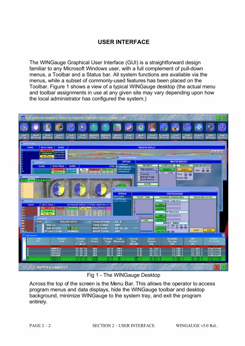
The WINGauge Graphical User Interface (GUI) is a straightforward designfamiliar to any Microsoft Windows user, with a full complement of pull-downmenus, a Toolbar and a Status bar. All system functions are available via themenus, while a subset of commonly-used features has been placed on theToolbar. Figure 1 shows a view of a typical WINGauge desktop (the actual menuand toolbar assignments in use at any given site may vary depending upon howthe local administrator has configured the system.)
Fig 1 - The WINGauge Desktop
Across the top of the screen is the Menu Bar. This allows the operator to accessprogram menus and data displays, hide the WINGauge toolbar and desktopbackground, minimize WINGauge to the system tray, and exit the programentirely.
7/16/2019 3900 Manual
http://slidepdf.com/reader/full/3900-manual 13/266
WINGAUGE v5.0 Rel SECTION 2 – USER INTERFACE PAGE 2 –3
Just below the Menu Bar is the Tool Bar. This consists of a row of icons, each of which will invoke a particular system display when clicked with the mouse. Thecontents of the Tool Bar are fully configurable by the system administrator.
The large central portion of the screen is where information displays and pop-upwindows appear, as shown above.
Along the bottom edge of the screen is the system Status Bar. This contains theLoop Status and Activity indicators and may optionally contain other pieces of information.

7/16/2019 3900 Manual
http://slidepdf.com/reader/full/3900-manual 14/266
PAGE 2 – 4 SECTION 2 – USER INTERFACE WINGAUGE v5.0 Rel..

7/16/2019 3900 Manual
http://slidepdf.com/reader/full/3900-manual 15/266
WINGAUGE v5.0 Rel SECTION 3 – QUICKSTART GUIDE PAGE 3 –1
SECTION 3
7/16/2019 3900 Manual
http://slidepdf.com/reader/full/3900-manual 16/266
PAGE 3 – 2 SECTION 3 – QUICKSTART GUIDE WINGAUGE v5.0 Rel.
QUICKSTART GUIDE
This section provides instruction on high-level preparation and configuration of the MCG3900. It is assumed that the user interface (menu and toolbars) is usingthe default layout, and that the loop configuration file has been properly initializedfor communication with the gauge field. Detailed information on field loop andinterface settings is available in the Administrator's Manual (supplied separately.)It is further assumed that all requisite strapping table data points have beenpreviously entered.
These specific data items will be discussed in some detail below:
1. Adding tanks into the system.
2. Set unique identifiers for each tank.
3. Set gauge address, loop and communications protocol
4. Set strapping table numbers and tank total capacity.
5. Set alarm points.
Entry of site-specific data is normally performed by L&J Technologies personnelprior to shipment, if this information is made available by the customer. This is sothe customer can place the unit into service immediately, although. It isrecommended that the customer verify all configuration information upon receiptof the system.
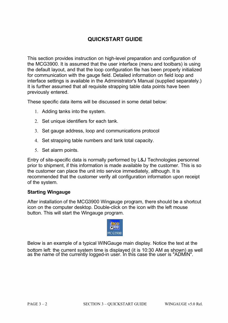
Starting Wingauge
After installation of the MCG3900 Wingauge program, there should be a shortcuticon on the computer desktop. Double-click on the icon with the left mousebutton. This will start the Wingauge program.
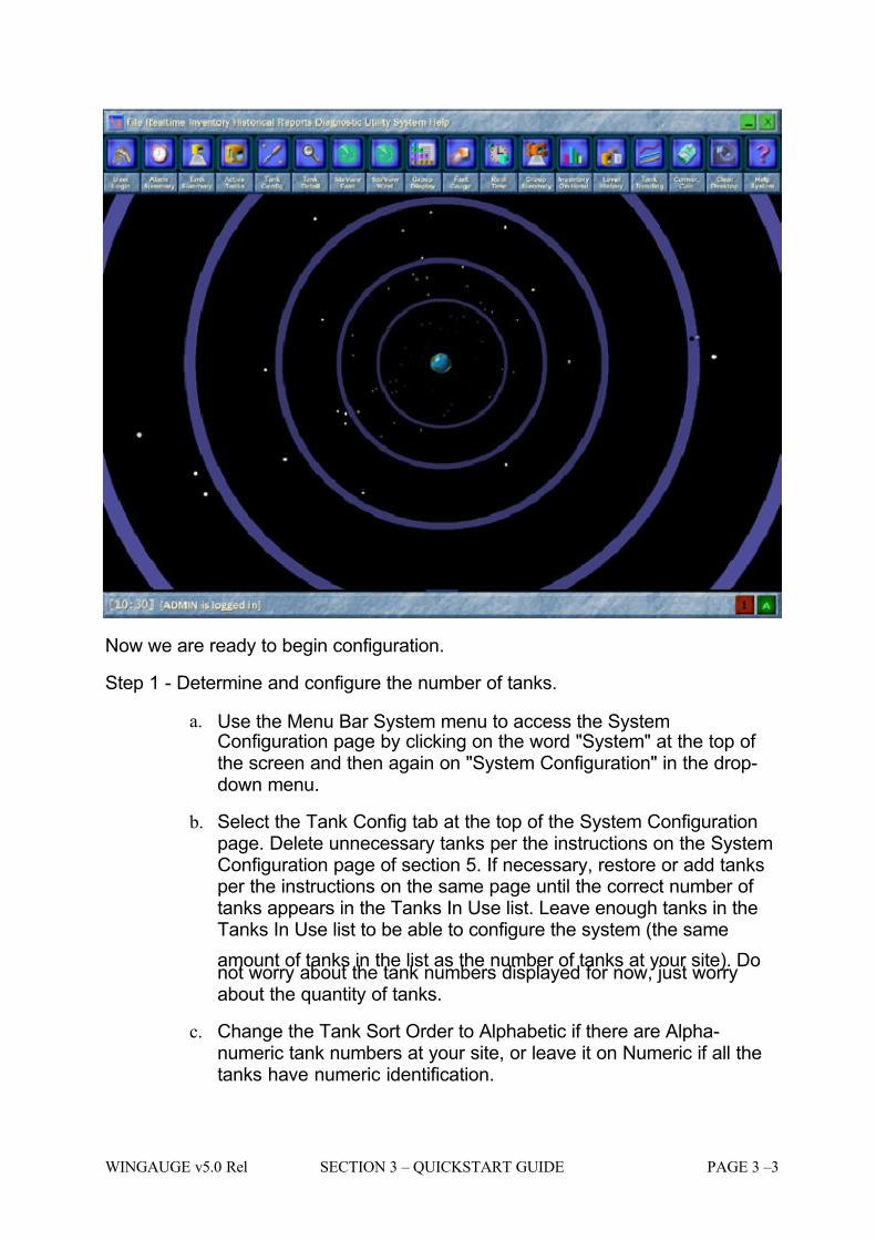
Below is an example of a typical WINGauge main display. Notice the text at the
bottom left: the current system time is displayed (it is 10:30 AM as shown) as wellas the name of the currently logged-in user. In this case the user is "ADMIN".
7/16/2019 3900 Manual
http://slidepdf.com/reader/full/3900-manual 17/266
WINGAUGE v5.0 Rel SECTION 3 – QUICKSTART GUIDE PAGE 3 –3
Now we are ready to begin configuration.
Step 1 - Determine and configure the number of tanks.
a. Use the Menu Bar System menu to access the SystemConfiguration page by clicking on the word "System" at the top of the screen and then again on "System Configuration" in the drop-down menu.
b. Select the Tank Config tab at the top of the System Configurationpage. Delete unnecessary tanks per the instructions on the SystemConfiguration page of section 5. If necessary, restore or add tanksper the instructions on the same page until the correct number of tanks appears in the Tanks In Use list. Leave enough tanks in theTanks In Use list to be able to configure the system (the same
amount of tanks in the list as the number of tanks at your site). Donot worry about the tank numbers displayed for now, just worryabout the quantity of tanks.
c. Change the Tank Sort Order to Alphabetic if there are Alpha-numeric tank numbers at your site, or leave it on Numeric if all thetanks have numeric identification.

7/16/2019 3900 Manual
http://slidepdf.com/reader/full/3900-manual 18/266
PAGE 3 – 4 SECTION 3 – QUICKSTART GUIDE WINGAUGE v5.0 Rel.
d. Close the screen by clicking the OK button in the lower left corner of the System Configuration display page.
Step 2 - Set the Tank Numbers or Tank IDs.
a. Use the Menu Bar System menu to access the Tank Configurationpage by clicking on the item as in Step 1a above.
b. Use the Menu Bar File menu to access the User Login page byclicking on the item as in Step 1a above.
c. Login to the system by following the instructions on the User Loginpage in section 5.
d. Close the User Login page.
e. Click on the number to the right of the Tank ID field label. Note thatthe field is now highlighted.
f. Type a new tank number in the space provided. Use the delete keyto get rid of the previous Tank ID number. Use the Enter key on thekeyboard to save the new value.
g. Move to another tank by clicking the next number in the Tanks listin the left column of the Tank Configuration page.
h. Repeat Steps 2e through 2g until all tanks are renumbered.
7/16/2019 3900 Manual
http://slidepdf.com/reader/full/3900-manual 19/266
WINGAUGE v5.0 Rel SECTION 3 – QUICKSTART GUIDE PAGE 3 –5
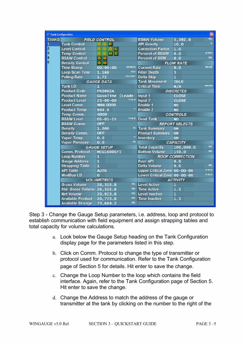
Step 3 - Change the Gauge Setup parameters, i.e. address, loop and protocol toestablish communication with field equipment and assign strapping tables andtotal capacity for volume calculations.
a. Look below the Gauge Setup heading on the Tank Configurationdisplay page for the parameters listed in this step.
b. Click on Comm. Protocol to change the type of transmitter or protocol used for communication. Refer to the Tank Configuration
page of Section 5 for details. Hit enter to save the change.
c. Change the Loop Number to the loop which contains the fieldinterface. Again, refer to the Tank Configuration page of Section 5.Hit enter to save the change.
d. Change the Address to match the address of the gauge or transmitter at the tank by clicking on the number to the right of the
7/16/2019 3900 Manual
http://slidepdf.com/reader/full/3900-manual 20/266
PAGE 3 – 6 SECTION 3 – QUICKSTART GUIDE WINGAUGE v5.0 Rel.
Gauge Address field label. The address should be between 1 and127. Check with the installer of the gauge or transmitter to find thecorrect address. Hit enter to save the change.
e. Assign the tank to a strapping table by first verifying entry of theStrapping Table (see the Strapping Table pages of Section 5), thennoting the strapping table number.
f. Click in the field to the right of the Strapping table field label on theTank Configuration page. Change the number to correspond to thenumber of the correct strapping table noted above. Hit enter to savethe change.
g. Click field to the right of the Total Capacity field label and type inthe Maximum Capacity of the tank. This value is usually found onthe hard copy tank strapping tables. Hit enter to save the value.
h. Turn on the Scan option for the Tank Control, Level Control andTemp Control fields. Refer to the Tank Configuration page of Section 5 for details.
i. Select another tank from the Tanks list.
j. Repeat steps 3b through 3i for all other tanks.
k. Close the Tank Configuration display page by clicking on the "x" inthe upper right corner of the display page.
Step 4 - Set values for alarming.
a. Open the Tank Detail page by Selecting the Tank Detail Pageoption in the File drop down menu of the Menu Bar.
b. Under the Alarm Controls section of this page you will see severalalarm settings. Change the alarm settings for...
i. HiHi Level
ii. High Level
iii. Low Level
iv. LoLo Level v. High Temp
vi. Low Temp
a. Refer to the Tank Detail page of Section 5 for more details.
7/16/2019 3900 Manual
http://slidepdf.com/reader/full/3900-manual 21/266
WINGAUGE v5.0 Rel SECTION 3 – QUICKSTART GUIDE PAGE 3 –7
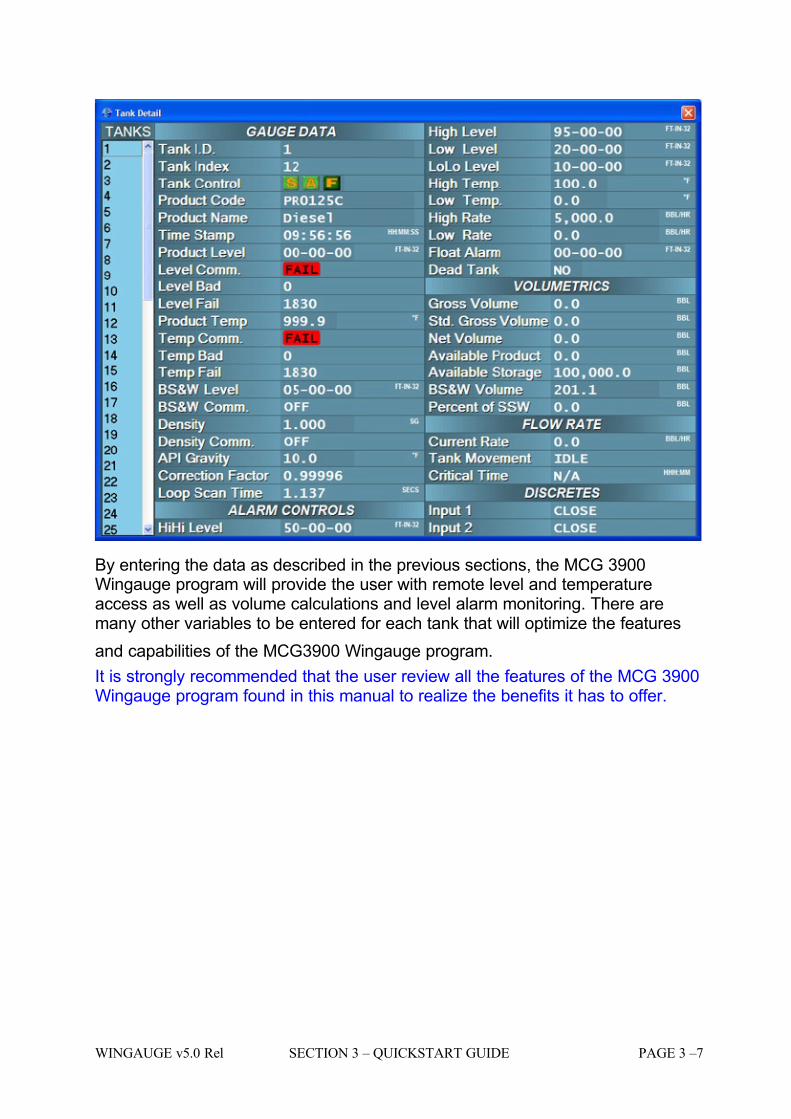
By entering the data as described in the previous sections, the MCG 3900Wingauge program will provide the user with remote level and temperatureaccess as well as volume calculations and level alarm monitoring. There aremany other variables to be entered for each tank that will optimize the features
and capabilities of the MCG3900 Wingauge program.
It is strongly recommended that the user review all the features of the MCG 3900Wingauge program found in this manual to realize the benefits it has to offer.

7/16/2019 3900 Manual
http://slidepdf.com/reader/full/3900-manual 22/266
PAGE 3 – 8 SECTION 3 – QUICKSTART GUIDE WINGAUGE v5.0 Rel.

7/16/2019 3900 Manual
http://slidepdf.com/reader/full/3900-manual 23/266
WINGAUGE v5.0 Rel. SECTION 4 – MAIN MENU PAGE 4 –1
SECTION 4
7/16/2019 3900 Manual
http://slidepdf.com/reader/full/3900-manual 24/266
PAGE 4 – 2 SECTION 4 – MAIN MENU WINGAUGE v5.0 Rel.
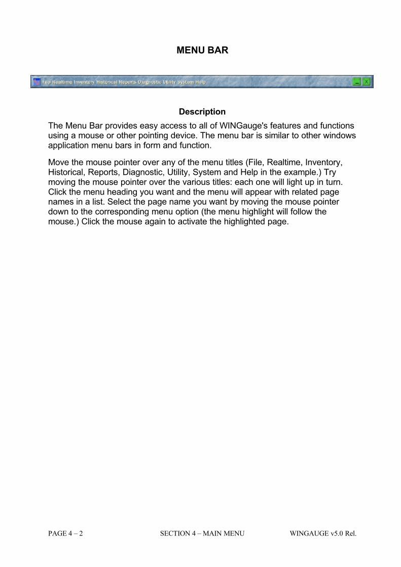
MENU BAR
Description
The Menu Bar provides easy access to all of WINGauge's features and functionsusing a mouse or other pointing device. The menu bar is similar to other windowsapplication menu bars in form and function.
Move the mouse pointer over any of the menu titles (File, Realtime, Inventory,Historical, Reports, Diagnostic, Utility, System and Help in the example.) Trymoving the mouse pointer over the various titles: each one will light up in turn.Click the menu heading you want and the menu will appear with related pagenames in a list. Select the page name you want by moving the mouse pointer down to the corresponding menu option (the menu highlight will follow themouse.) Click the mouse again to activate the highlighted page.
7/16/2019 3900 Manual
http://slidepdf.com/reader/full/3900-manual 25/266
WINGAUGE v5.0 Rel. SECTION 4 – MAIN MENU PAGE 4 –3
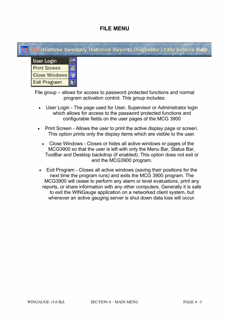
FILE MENU
File group – allows for access to password protected functions and normalprogram activation control. This group includes:
• User Login - The page used for User, Supervisor or Administrator loginwhich allows for access to the password protected functions and
configurable fields on the user pages of the MCG 3900
• Print Screen - Allows the user to print the active display page or screen.This option prints only the display items which are visible to the user.
• Close Windows - Closes or hides all active windows or pages of theMCG3900 so that the user is left with only the Menu Bar, Status Bar,
ToolBar and Desktop backdrop (if enabled). This option does not exit or end the MCG3900 program.
• Exit Program - Closes all active windows (saving their positions for thenext time the program runs) and exits the MCG 3900 program. The
MCG3900 will cease to perform any alarm or level evaluations, print anyreports, or share information with any other computers. Generally it is safe
to exit the WINGauge application on a networked client system, butwhenever an active gauging server is shut down data loss will occur.
7/16/2019 3900 Manual
http://slidepdf.com/reader/full/3900-manual 26/266
PAGE 4 – 4 SECTION 4 – MAIN MENU WINGAUGE v5.0 Rel.
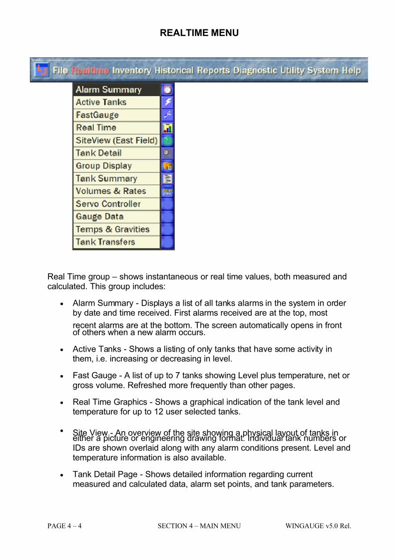
REALTIME MENU
Real Time group – shows instantaneous or real time values, both measured andcalculated. This group includes:
• Alarm Summary - Displays a list of all tanks alarms in the system in order by date and time received. First alarms received are at the top, most
recent alarms are at the bottom. The screen automatically opens in frontof others when a new alarm occurs.
• Active Tanks - Shows a listing of only tanks that have some activity inthem, i.e. increasing or decreasing in level.
• Fast Gauge - A list of up to 7 tanks showing Level plus temperature, net or gross volume. Refreshed more frequently than other pages.
• Real Time Graphics - Shows a graphical indication of the tank level andtemperature for up to 12 user selected tanks.
• Site View - An overview of the site showing a physical layout of tanks ineither a picture or engineering drawing format. Individual tank numbers or IDs are shown overlaid along with any alarm conditions present. Level andtemperature information is also available.
• Tank Detail Page - Shows detailed information regarding currentmeasured and calculated data, alarm set points, and tank parameters.
7/16/2019 3900 Manual
http://slidepdf.com/reader/full/3900-manual 27/266
WINGAUGE v5.0 Rel. SECTION 4 – MAIN MENU PAGE 4 –5
• Tank Groups - User configurable display which shows tabular data per user requirements. Data columns and Tank Numbers displayed arechangeable.
• Tank Summary Display - Display showing all tanks in the system listed intabular form with certain standard measured and calculated valuesdisplayed. Normally contains Level, Temperature and Volume informationat a minimum.
• Volumes & Rates - Display shows summary volumes and rate calculationsfor individual tanks. Multiple pages can be opened for comparison withother tanks.
• Servo Controller - Optional display for remotely controlling L&J MCG1500-series servo gauges, and monitoring gauge operational status.
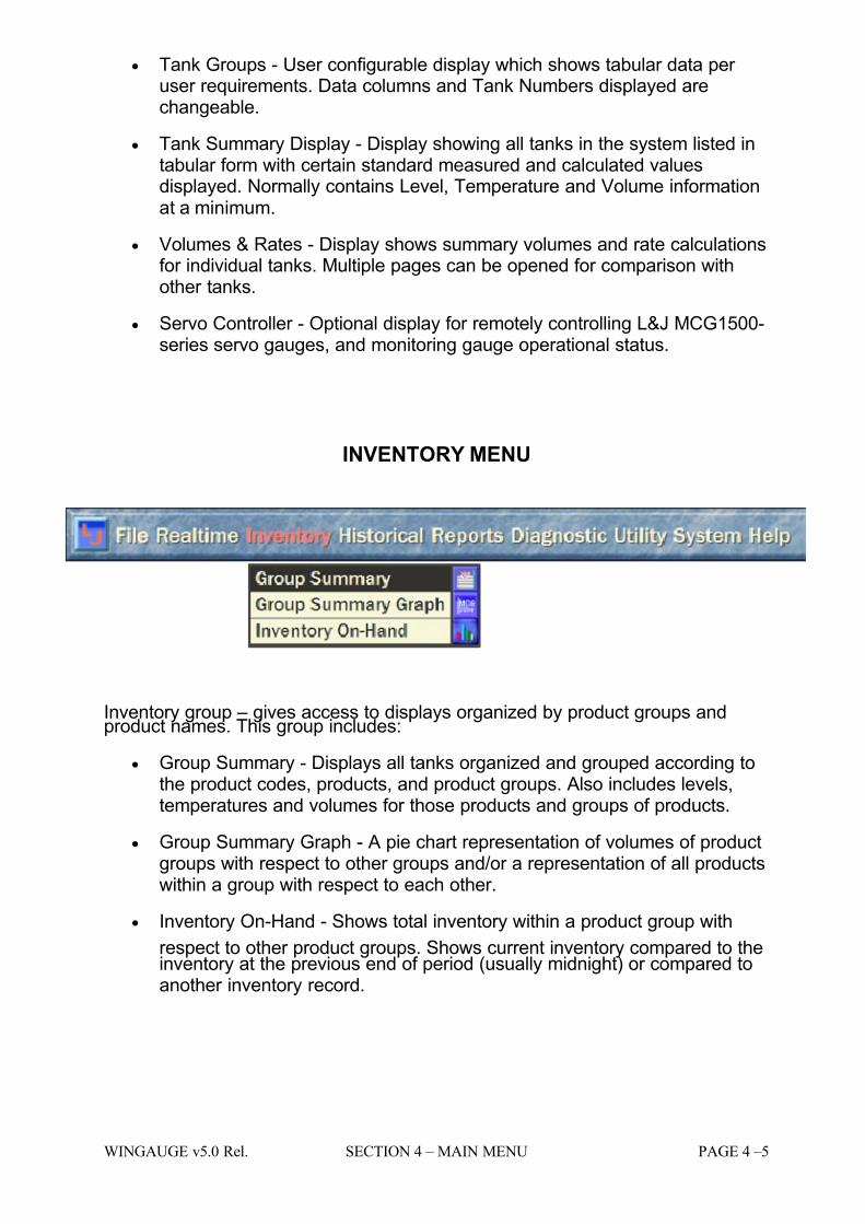
INVENTORY MENU
Inventory group – gives access to displays organized by product groups andproduct names. This group includes:
• Group Summary - Displays all tanks organized and grouped according tothe product codes, products, and product groups. Also includes levels,temperatures and volumes for those products and groups of products.
• Group Summary Graph - A pie chart representation of volumes of productgroups with respect to other groups and/or a representation of all productswithin a group with respect to each other.
• Inventory On-Hand - Shows total inventory within a product group with
respect to other product groups. Shows current inventory compared to theinventory at the previous end of period (usually midnight) or compared toanother inventory record.
7/16/2019 3900 Manual
http://slidepdf.com/reader/full/3900-manual 28/266
PAGE 4 – 6 SECTION 4 – MAIN MENU WINGAUGE v5.0 Rel.
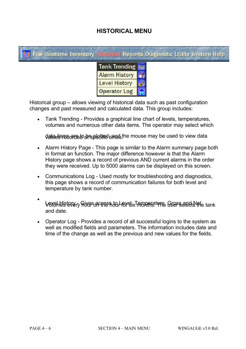
HISTORICAL MENU
Historical group – allows viewing of historical data such as past configurationchanges and past measured and calculated data. This group includes:
• Tank Trending - Provides a graphical line chart of levels, temperatures,volumes and numerous other data items. The operator may select which
data items are to be plotted, and the mouse may be used to view datavalues recorded at specific times.
• Alarm History Page - This page is similar to the Alarm summary page bothin format an function. The major difference however is that the AlarmHistory page shows a record of previous AND current alarms in the order they were received. Up to 5000 alarms can be displayed on this screen.
• Communications Log - Used mostly for troubleshooting and diagnostics,this page shows a record of communication failures for both level andtemperature by tank number.
•
Level History - Gives access to Level, Temperature, Gross and NetVolumes every hour on the hour for six months. The user selects the tankand date.
• Operator Log - Provides a record of all successful logins to the system aswell as modified fields and parameters. The information includes date andtime of the change as well as the previous and new values for the fields.
7/16/2019 3900 Manual
http://slidepdf.com/reader/full/3900-manual 29/266
WINGAUGE v5.0 Rel. SECTION 4 – MAIN MENU PAGE 4 –7
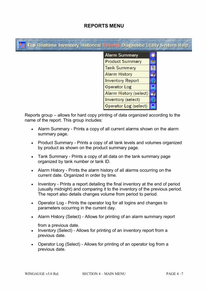
REPORTS MENU
Reports group – allows for hard copy printing of data organized according to thename of the report. This group includes:
• Alarm Summary - Prints a copy of all current alarms shown on the alarmsummary page.
• Product Summary - Prints a copy of all tank levels and volumes organizedby product as shown on the product summary page.
• Tank Summary - Prints a copy of all data on the tank summary pageorganized by tank number or tank ID.
• Alarm History - Prints the alarm history of all alarms occurring on thecurrent date. Organized in order by time.
• Inventory - Prints a report detailing the final inventory at the end of period(usually midnight) and comparing it to the inventory of the previous period.The report also details changes volume from period to period.
• Operator Log - Prints the operator log for all logins and changes toparameters occurring in the current day.
• Alarm History (Select) - Allows for printing of an alarm summary report
from a previous date.
• Inventory (Select) - Allows for printing of an inventory report from aprevious date.
• Operator Log (Select) - Allows for printing of an operator log from aprevious date.
7/16/2019 3900 Manual
http://slidepdf.com/reader/full/3900-manual 30/266
PAGE 4 – 8 SECTION 4 – MAIN MENU WINGAUGE v5.0 Rel.
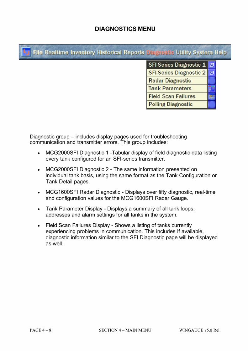
DIAGNOSTICS MENU
Diagnostic group – includes display pages used for troubleshootingcommunication and transmitter errors. This group includes:
• MCG2000SFI Diagnostic 1 -Tabular display of field diagnostic data listingevery tank configured for an SFI-series transmitter.
• MCG2000SFI Diagnostic 2 - The same information presented onindividual tank basis, using the same format as the Tank Configuration or Tank Detail pages.
• MCG1600SFI Radar Diagnostic - Displays over fifty diagnostic, real-timeand configuration values for the MCG1600SFI Radar Gauge.
• Tank Parameter Display - Displays a summary of all tank loops,addresses and alarm settings for all tanks in the system.
• Field Scan Failures Display - Shows a listing of tanks currentlyexperiencing problems in communication. This includes If available,diagnostic information similar to the SFI Diagnostic page will be displayedas well.
7/16/2019 3900 Manual
http://slidepdf.com/reader/full/3900-manual 31/266
WINGAUGE v5.0 Rel. SECTION 4 – MAIN MENU PAGE 4 –9
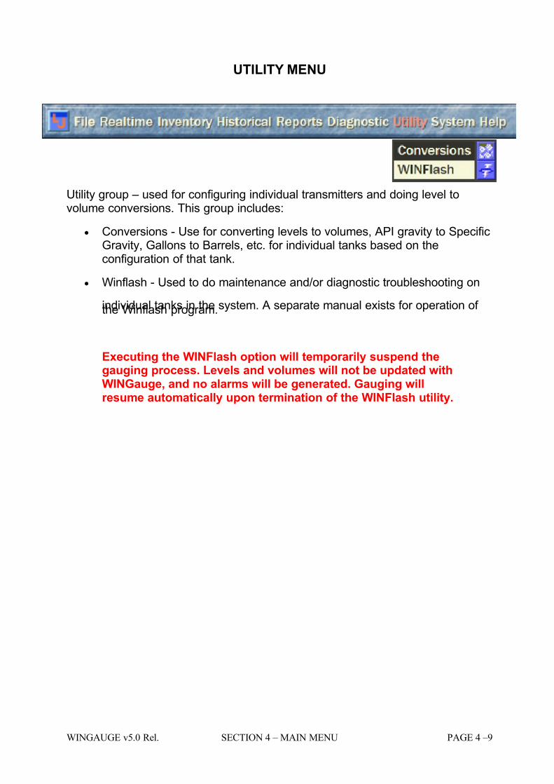
UTILITY MENU
Utility group – used for configuring individual transmitters and doing level tovolume conversions. This group includes:
• Conversions - Use for converting levels to volumes, API gravity to SpecificGravity, Gallons to Barrels, etc. for individual tanks based on theconfiguration of that tank.
• Winflash - Used to do maintenance and/or diagnostic troubleshooting on
individual tanks in the system. A separate manual exists for operation of the Winflash program.
Executing the WINFlash option will temporarily suspend thegauging process. Levels and volumes will not be updated withWINGauge, and no alarms will be generated. Gauging willresume automatically upon termination of the WINFlash utility.
7/16/2019 3900 Manual
http://slidepdf.com/reader/full/3900-manual 32/266
PAGE 4 – 10 SECTION 4 – MAIN MENU WINGAUGE v5.0 Rel.
SYSTEM MENU
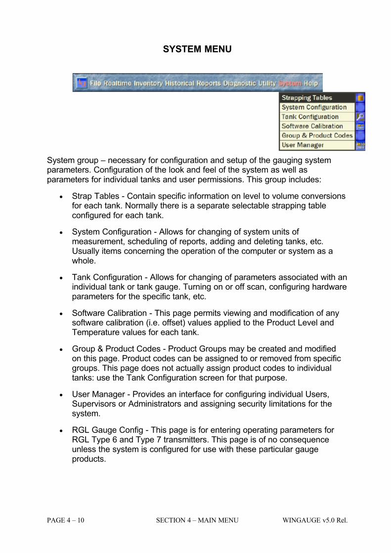
System group – necessary for configuration and setup of the gauging systemparameters. Configuration of the look and feel of the system as well asparameters for individual tanks and user permissions. This group includes:
• Strap Tables - Contain specific information on level to volume conversionsfor each tank. Normally there is a separate selectable strapping tableconfigured for each tank.
• System Configuration - Allows for changing of system units of measurement, scheduling of reports, adding and deleting tanks, etc.Usually items concerning the operation of the computer or system as awhole.
• Tank Configuration - Allows for changing of parameters associated with anindividual tank or tank gauge. Turning on or off scan, configuring hardwareparameters for the specific tank, etc.
• Software Calibration - This page permits viewing and modification of anysoftware calibration (i.e. offset) values applied to the Product Level andTemperature values for each tank.
• Group & Product Codes - Product Groups may be created and modifiedon this page. Product codes can be assigned to or removed from specificgroups. This page does not actually assign product codes to individualtanks: use the Tank Configuration screen for that purpose.
• User Manager - Provides an interface for configuring individual Users,Supervisors or Administrators and assigning security limitations for thesystem.
• RGL Gauge Config - This page is for entering operating parameters for RGL Type 6 and Type 7 transmitters. This page is of no consequenceunless the system is configured for use with these particular gaugeproducts.
7/16/2019 3900 Manual
http://slidepdf.com/reader/full/3900-manual 33/266
WINGAUGE v5.0 Rel. SECTION 4 – MAIN MENU PAGE 4 –11
HELP MENU
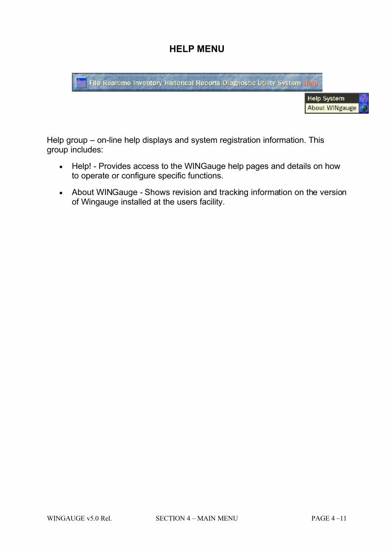
Help group – on-line help displays and system registration information. Thisgroup includes:
• Help! - Provides access to the WINGauge help pages and details on howto operate or configure specific functions.
• About WINGauge - Shows revision and tracking information on the versionof Wingauge installed at the users facility.
7/16/2019 3900 Manual
http://slidepdf.com/reader/full/3900-manual 34/266
PAGE 4 – 12 SECTION 4 – MAIN MENU WINGAUGE v5.0 Rel.
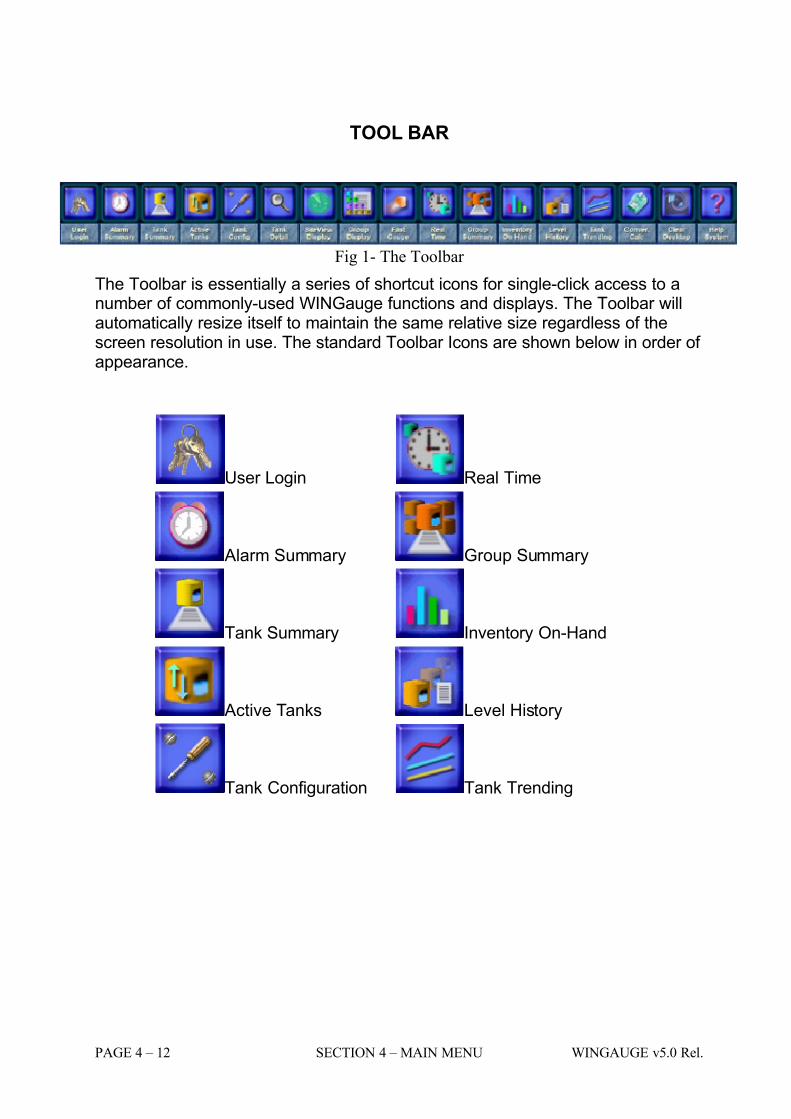
TOOL BAR
Fig 1- The Toolbar
The Toolbar is essentially a series of shortcut icons for single-click access to anumber of commonly-used WINGauge functions and displays. The Toolbar willautomatically resize itself to maintain the same relative size regardless of thescreen resolution in use. The standard Toolbar Icons are shown below in order of appearance.
User Login Real Time
Alarm Summary Group Summary
Tank Summary Inventory On-Hand
Active Tanks Level History
Tank Configuration Tank Trending
7/16/2019 3900 Manual
http://slidepdf.com/reader/full/3900-manual 35/266
WINGAUGE v5.0 Rel. SECTION 4 – MAIN MENU PAGE 4 –13
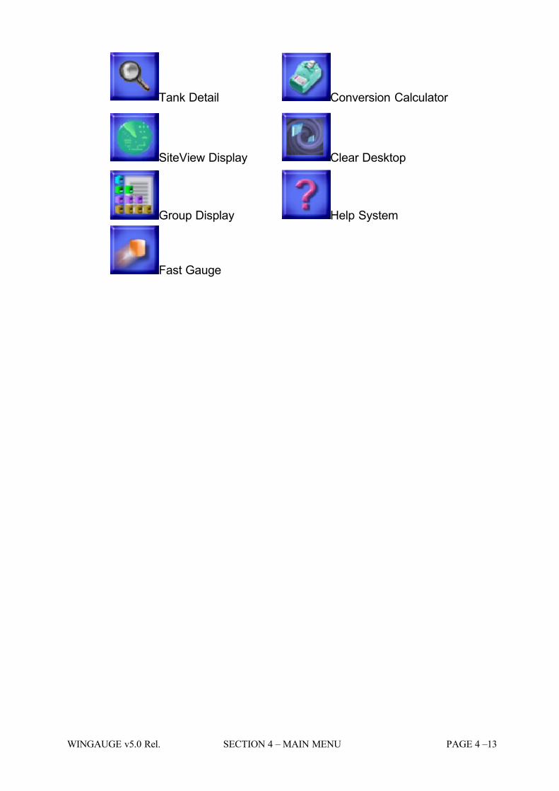
Tank Detail Conversion Calculator
SiteView Display Clear Desktop
Group Display Help System
Fast Gauge
7/16/2019 3900 Manual
http://slidepdf.com/reader/full/3900-manual 36/266
PAGE 4 – 14 SECTION 4 – MAIN MENU WINGAUGE v5.0 Rel.
STATUS BAR
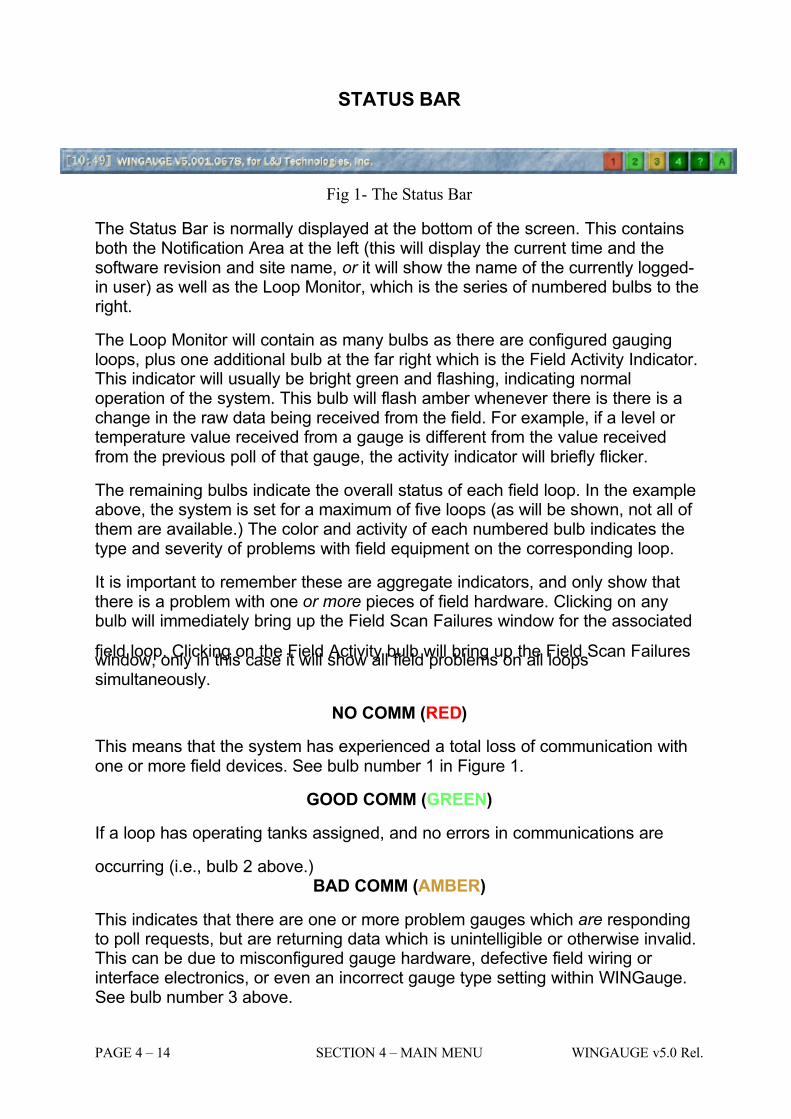
Fig 1- The Status Bar
The Status Bar is normally displayed at the bottom of the screen. This containsboth the Notification Area at the left (this will display the current time and thesoftware revision and site name, or it will show the name of the currently logged-in user) as well as the Loop Monitor, which is the series of numbered bulbs to theright.
The Loop Monitor will contain as many bulbs as there are configured gaugingloops, plus one additional bulb at the far right which is the Field Activity Indicator.This indicator will usually be bright green and flashing, indicating normaloperation of the system. This bulb will flash amber whenever there is there is achange in the raw data being received from the field. For example, if a level or temperature value received from a gauge is different from the value receivedfrom the previous poll of that gauge, the activity indicator will briefly flicker.
The remaining bulbs indicate the overall status of each field loop. In the exampleabove, the system is set for a maximum of five loops (as will be shown, not all of them are available.) The color and activity of each numbered bulb indicates thetype and severity of problems with field equipment on the corresponding loop.
It is important to remember these are aggregate indicators, and only show thatthere is a problem with one or more pieces of field hardware. Clicking on anybulb will immediately bring up the Field Scan Failures window for the associated
field loop. Clicking on the Field Activity bulb will bring up the Field Scan Failureswindow, only in this case it will show all field problems on all loopssimultaneously.
NO COMM (RED)
This means that the system has experienced a total loss of communication withone or more field devices. See bulb number 1 in Figure 1.
GOOD COMM (GREEN)
If a loop has operating tanks assigned, and no errors in communications are
occurring (i.e., bulb 2 above.)BAD COMM (AMBER)
This indicates that there are one or more problem gauges which are respondingto poll requests, but are returning data which is unintelligible or otherwise invalid.This can be due to misconfigured gauge hardware, defective field wiring or interface electronics, or even an incorrect gauge type setting within WINGauge.See bulb number 3 above.
7/16/2019 3900 Manual
http://slidepdf.com/reader/full/3900-manual 37/266
WINGAUGE v5.0 Rel. SECTION 4 – MAIN MENU PAGE 4 –15
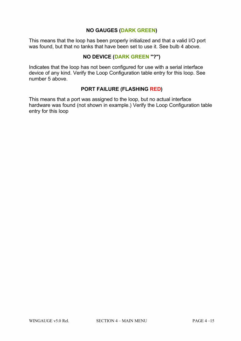
NO GAUGES (DARK GREEN)
This means that the loop has been properly initialized and that a valid I/O portwas found, but that no tanks that have been set to use it. See bulb 4 above.
NO DEVICE (DARK GREEN "?")
Indicates that the loop has not been configured for use with a serial interfacedevice of any kind. Verify the Loop Configuration table entry for this loop. Seenumber 5 above.
PORT FAILURE (FLASHING RED)
This means that a port was assigned to the loop, but no actual interfacehardware was found (not shown in example.) Verify the Loop Configuration tableentry for this loop
7/16/2019 3900 Manual
http://slidepdf.com/reader/full/3900-manual 38/266
PAGE 4 – 16 SECTION 4 – MAIN MENU WINGAUGE v5.0 Rel.
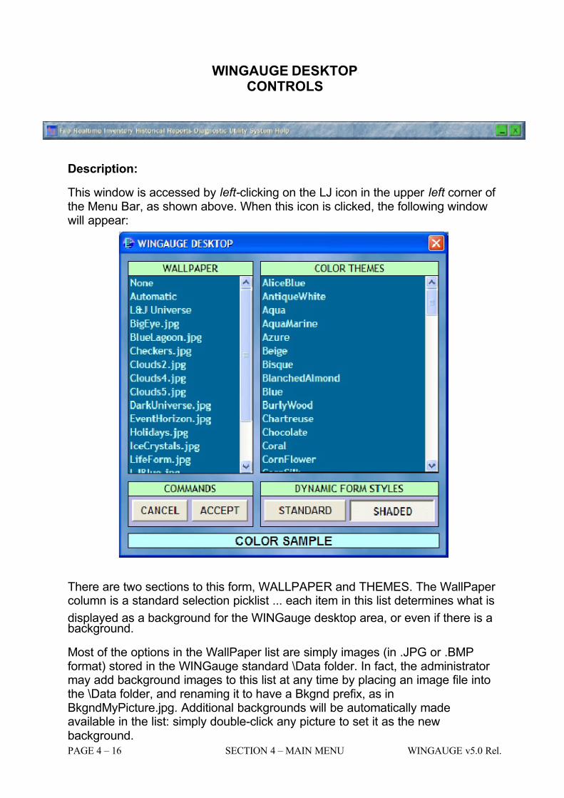
WINGAUGE DESKTOPCONTROLS
Description:
This window is accessed by left-clicking on the LJ icon in the upper left corner of the Menu Bar, as shown above. When this icon is clicked, the following windowwill appear:
There are two sections to this form, WALLPAPER and THEMES. The WallPaper column is a standard selection picklist ... each item in this list determines what is
displayed as a background for the WINGauge desktop area, or even if there is abackground.
Most of the options in the WallPaper list are simply images (in .JPG or .BMPformat) stored in the WINGauge standard \Data folder. In fact, the administrator may add background images to this list at any time by placing an image file intothe \Data folder, and renaming it to have a Bkgnd prefix, as inBkgndMyPicture.jpg. Additional backgrounds will be automatically madeavailable in the list: simply double-click any picture to set it as the newbackground.
7/16/2019 3900 Manual
http://slidepdf.com/reader/full/3900-manual 39/266
WINGAUGE v5.0 Rel. SECTION 4 – MAIN MENU PAGE 4 –17
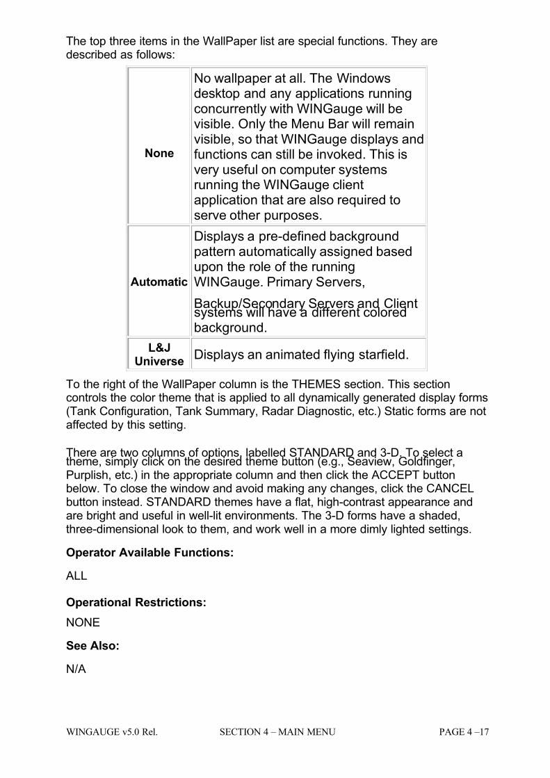
The top three items in the WallPaper list are special functions. They aredescribed as follows:
None
No wallpaper at all. The Windowsdesktop and any applications runningconcurrently with WINGauge will bevisible. Only the Menu Bar will remainvisible, so that WINGauge displays andfunctions can still be invoked. This isvery useful on computer systemsrunning the WINGauge clientapplication that are also required toserve other purposes.
Automatic
Displays a pre-defined backgroundpattern automatically assigned basedupon the role of the runningWINGauge. Primary Servers,
Backup/Secondary Servers and Clientsystems will have a different coloredbackground.
L&JUniverse
Displays an animated flying starfield.
To the right of the WallPaper column is the THEMES section. This sectioncontrols the color theme that is applied to all dynamically generated display forms(Tank Configuration, Tank Summary, Radar Diagnostic, etc.) Static forms are notaffected by this setting.
There are two columns of options, labelled STANDARD and 3-D. To select atheme, simply click on the desired theme button (e.g., Seaview, Goldfinger,Purplish, etc.) in the appropriate column and then click the ACCEPT buttonbelow. To close the window and avoid making any changes, click the CANCELbutton instead. STANDARD themes have a flat, high-contrast appearance andare bright and useful in well-lit environments. The 3-D forms have a shaded,three-dimensional look to them, and work well in a more dimly lighted settings.
Operator Available Functions:
ALL
Operational Restrictions:
NONE
See Also:
N/A

7/16/2019 3900 Manual
http://slidepdf.com/reader/full/3900-manual 40/266
PAGE 4 – 18 SECTION 4 – MAIN MENU WINGAUGE v5.0 Rel.

7/16/2019 3900 Manual
http://slidepdf.com/reader/full/3900-manual 41/266
WINGAUGE v5.0 Rel. SECTION 5 – DISPLAY TYPE OVERVIEW PAGE 5 –1
SECTION 5
7/16/2019 3900 Manual
http://slidepdf.com/reader/full/3900-manual 42/266
PAGE 5 – 2 SECTION 5 – DISPLAY TYPE OVERVIEW WINGAUGE v5.0 Rel.
DISPLAY TYPES
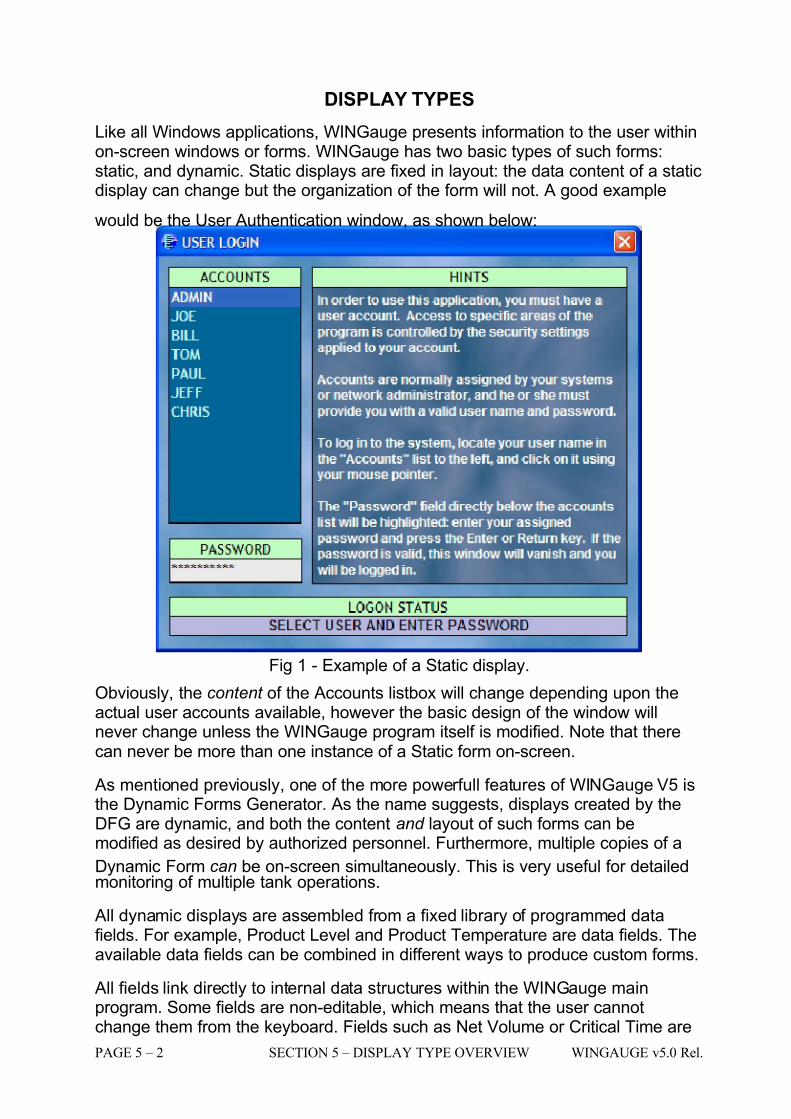
Like all Windows applications, WINGauge presents information to the user withinon-screen windows or forms. WINGauge has two basic types of such forms:static, and dynamic. Static displays are fixed in layout: the data content of a staticdisplay can change but the organization of the form will not. A good example
would be the User Authentication window, as shown below:
Fig 1 - Example of a Static display.
Obviously, the content of the Accounts listbox will change depending upon theactual user accounts available, however the basic design of the window willnever change unless the WINGauge program itself is modified. Note that therecan never be more than one instance of a Static form on-screen.
As mentioned previously, one of the more powerfull features of WINGauge V5 isthe Dynamic Forms Generator. As the name suggests, displays created by theDFG are dynamic, and both the content and layout of such forms can bemodified as desired by authorized personnel. Furthermore, multiple copies of a
Dynamic Form can be on-screen simultaneously. This is very useful for detailedmonitoring of multiple tank operations.
All dynamic displays are assembled from a fixed library of programmed datafields. For example, Product Level and Product Temperature are data fields. Theavailable data fields can be combined in different ways to produce custom forms.
All fields link directly to internal data structures within the WINGauge mainprogram. Some fields are non-editable, which means that the user cannotchange them from the keyboard. Fields such as Net Volume or Critical Time are
7/16/2019 3900 Manual
http://slidepdf.com/reader/full/3900-manual 43/266
WINGAUGE v5.0 Rel. SECTION 5 – DISPLAY TYPE OVERVIEW PAGE 5 –3
read-only fields. Others are editable, which means that the user can change their values from the keyboard. Gauge Type and Float Alarm Level are examples of editable fields.
Data fields have two components: the legend area and the data area. The legendarea simply describes the purpose of the field (e.g. Product Code or API Gravity).The data area displays the contents of the field and, in the case of editable fields,is where the user types new information.
Figure 2 below has examples of both editable and non-editable fields. Editablefields are denoted by a light background in the data area (contrast Product Levelwith Level Comm.)
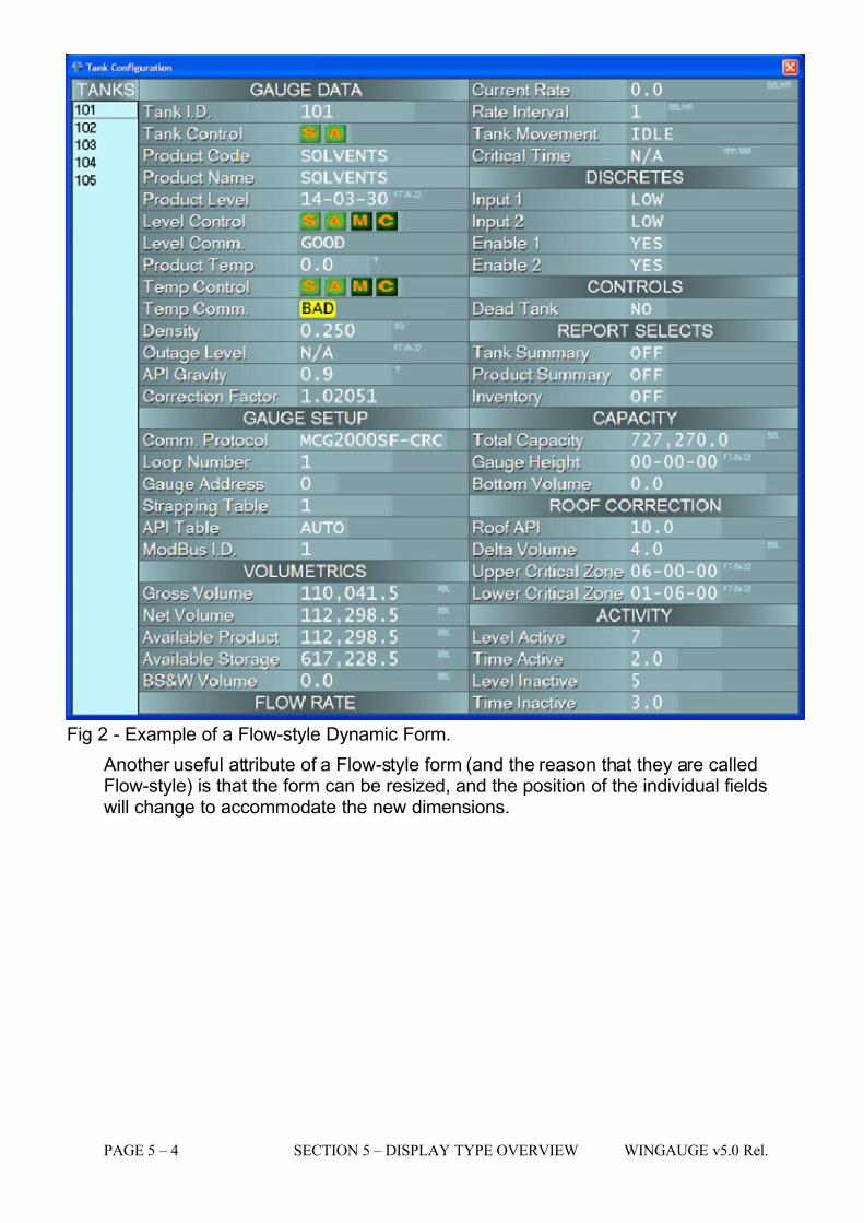
There are two basic styles of Dynamic Forms: Flow and Tabular. Flow forms aretypically for data-entry forms, and for displaying information about a specific tank.Tabular forms are for displaying table-based information for multiple tanks.
Below is an example of a Flow-style display. Notice that all of the data fieldsapply to only one tank (in this case, Tank 101). The TANKS listbox at the left isused to select which tank is being viewed: when a tank is chosen, all fields will
instantly update to reflect the current status of the newly-selected tank.
Holding the mouse over the legend area of any field for a few seconds will bringup a capsule description of that field (called a tooltip.) Moving the mouse willmake the tooltip disappear.
7/16/2019 3900 Manual
http://slidepdf.com/reader/full/3900-manual 44/266
PAGE 5 – 4 SECTION 5 – DISPLAY TYPE OVERVIEW WINGAUGE v5.0 Rel.
Fig 2 - Example of a Flow-style Dynamic Form.
Another useful attribute of a Flow-style form (and the reason that they are calledFlow-style) is that the form can be resized, and the position of the individual fieldswill change to accommodate the new dimensions.
7/16/2019 3900 Manual
http://slidepdf.com/reader/full/3900-manual 45/266
WINGAUGE v5.0 Rel. SECTION 5 – DISPLAY TYPE OVERVIEW PAGE 5 –5
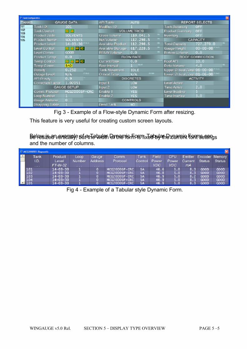
Fig 3 - Example of a Flow-style Dynamic Form after resizing.
This feature is very useful for creating custom screen layouts.
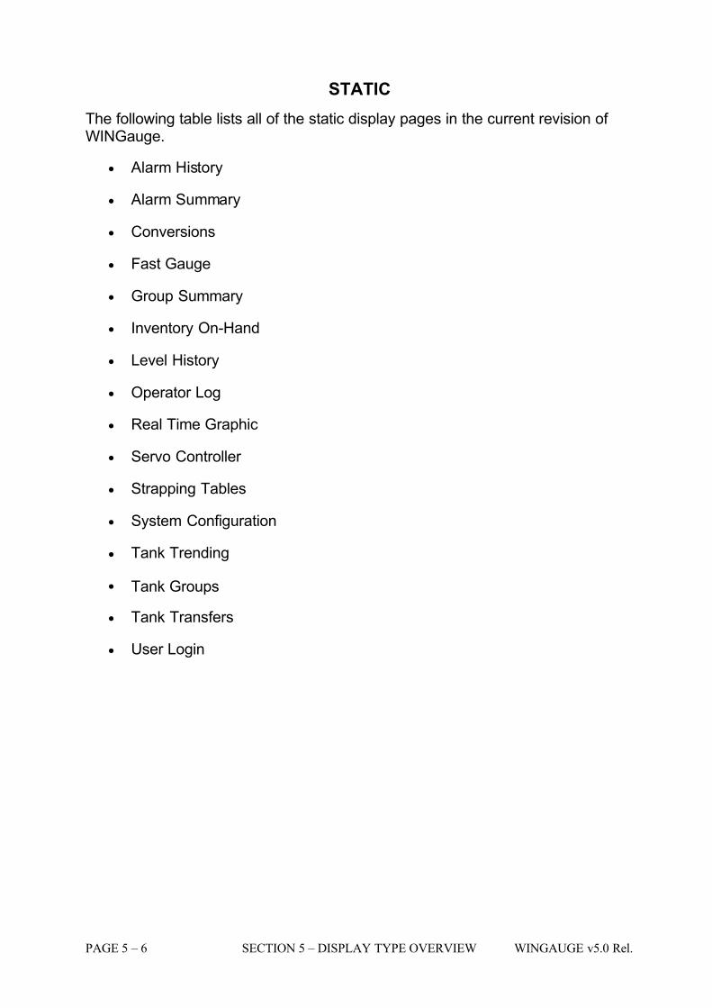
Below is an example of a Tabular Dynamic Form. Tabular Dynamic Forms canbe resized vertically, but the width of the form is fixed by the current font settingsand the number of columns.
Fig 4 - Example of a Tabular style Dynamic Form.
7/16/2019 3900 Manual
http://slidepdf.com/reader/full/3900-manual 46/266
PAGE 5 – 6 SECTION 5 – DISPLAY TYPE OVERVIEW WINGAUGE v5.0 Rel.
STATIC
The following table lists all of the static display pages in the current revision of WINGauge.
• Alarm History
• Alarm Summary
• Conversions
• Fast Gauge
• Group Summary
• Inventory On-Hand
• Level History
• Operator Log
• Real Time Graphic
• Servo Controller
• Strapping Tables
• System Configuration
• Tank Trending
• Tank Groups
• Tank Transfers
• User Login
7/16/2019 3900 Manual
http://slidepdf.com/reader/full/3900-manual 47/266
WINGAUGE v5.0 Rel. SECTION 5 – DISPLAY TYPE OVERVIEW PAGE 5 –7
DYNAMIC
The following table lists all of the dynamic display pages in the current revision of WINGauge. This information only pertains to the standard shipping version of WINGauge: and does not include any site-specific customizations or modifications.
• Active Tanks
• Polling Diagnostic
• Field Scan Failures
• Help System
• MCG2000SFI Diagnostic 1
• MCG2000SFI Diagnostic 2
• Radar Diagnostic
• Tank Configuration
• Tank Detail
• Tank Parameter
• Tank Summary
• SiteView
• Temps & Gravities
• Gauge Data
• Volumes & Rates

7/16/2019 3900 Manual
http://slidepdf.com/reader/full/3900-manual 48/266
PAGE 5 – 8 SECTION 5 – DISPLAY TYPE OVERVIEW WINGAUGE v5.0 Rel.

7/16/2019 3900 Manual
http://slidepdf.com/reader/full/3900-manual 49/266
WINGAUGE v5.0 Rel. SECTION 6 – STD DISPLAY DETAIL & CONFIG. PAGE 6 –1
SECTION 6
7/16/2019 3900 Manual
http://slidepdf.com/reader/full/3900-manual 50/266
PAGE 6 – 2 SECTION 6 – STD DISPLAY DETAIL & CONFIG. WINGAUGE v5.0 Rel.
STANDARD DISPLAYS
The pages in this section describes all of the displays (both static and dynamic)that ship in the standard WINGauge. The dynamic displays in use at anyparticular site may differ from those listed.
ACTIVE TANKS
Description:
The Active Tanks display will list all tanks that are currently experiencing achange in the volume of their contents. A number of different derived values aredisplayed here as well. Tanks which are not in an active state will not appear onthis display: tanks which are displayed but return to an idle condition will beautomatically removed from the list.
7/16/2019 3900 Manual
http://slidepdf.com/reader/full/3900-manual 51/266
WINGAUGE v5.0 Rel. SECTION 6 – STD DISPLAY DETAIL & CONFIG. PAGE 6 –3
Operator Available Functions:
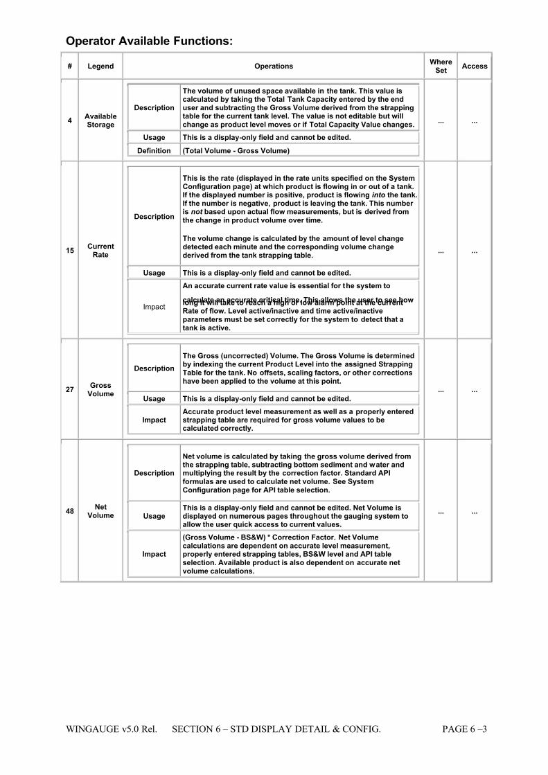
# Legend Operations WhereSet
Access
4 AvailableStorage
Description
The volume of unused space available in the tank. This value iscalculated by taking the Total Tank Capacity entered by the enduser and subtracting the Gross Volume derived from the strappingtable for the current tank level. The value is not editable but willchange as product level moves or if Total Capacity Value changes.
Usage This is a display-only field and cannot be edited. Definition (Total Volume - Gross Volume)
... ...
15 CurrentRate
Description
This is the rate (displayed in the rate units specified on the SystemConfiguration page) at which product is flowing in or out of a tank.If the displayed number is positive, product is flowing into the tank.If the number is negative, product is leaving the tank. This number is not based upon actual flow measurements, but is derived fromthe change in product volume over time.
The volume change is calculated by the amount of level changedetected each minute and the corresponding volume changederived from the tank strapping table.
Usage This is a display-only field and cannot be edited.
Impact
An accurate current rate value is essential for the system to
calculate an accurate critical time. This allows the user to see howlong it will take to reach a high or low alarm point at the currentRate of flow. Level active/inactive and time active/inactiveparameters must be set correctly for the system to detect that atank is active.
... ...
27 GrossVolume
Description The Gross (uncorrected) Volume. The Gross Volume is determinedby indexing the current Product Level into the assigned StrappingTable for the tank. No offsets, scaling factors, or other correctionshave been applied to the volume at this point.
Usage This is a display-only field and cannot be edited.
ImpactAccurate product level measurement as well as a properly enteredstrapping table are required for gross volume values to becalculated correctly.
... ...
48 NetVolume
Description
Net volume is calculated by taking the gross volume derived fromthe strapping table, subtracting bottom sediment and water andmultiplying the result by the correction factor. Standard APIformulas are used to calculate net volume. See SystemConfiguration page for API table selection.
Usage This is a display-only field and cannot be edited. Net Volume isdisplayed on numerous pages throughout the gauging system toallow the user quick access to current values.
Impact
(Gross Volume - BS&W) * Correction Factor. Net Volumecalculations are dependent on accurate level measurement,properly entered strapping tables, BS&W level and API tableselection. Available product is also dependent on accurate netvolume calculations.
... ...
7/16/2019 3900 Manual
http://slidepdf.com/reader/full/3900-manual 52/266
PAGE 6 – 4 SECTION 6 – STD DISPLAY DETAIL & CONFIG. WINGAUGE v5.0 Rel.
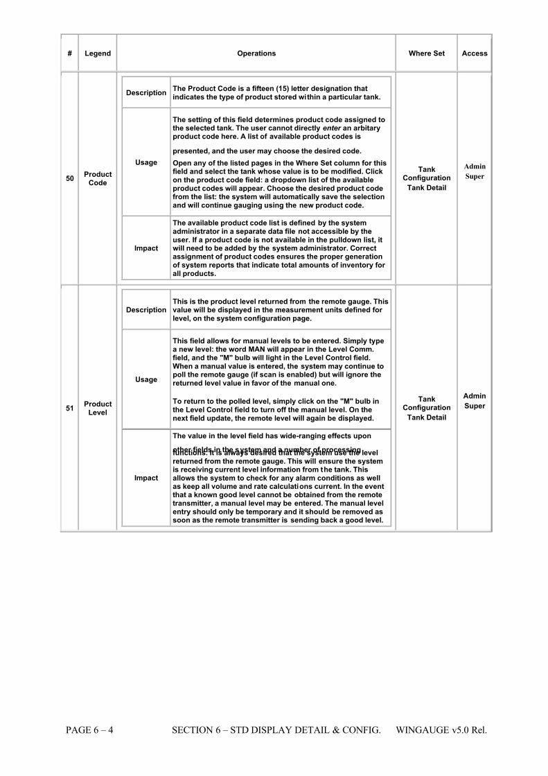
# Legend Operations Where Set Access
50 ProductCode
Description The Product Code is a fifteen (15) letter designation thatindicates the type of product stored within a particular tank.
Usage
The setting of this field determines product code assigned tothe selected tank. The user cannot directly enter an arbitaryproduct code here. A list of available product codes is
presented, and the user may choose the desired code. Open any of the listed pages in the Where Set column for thisfield and select the tank whose value is to be modified. Clickon the product code field: a dropdown list of the availableproduct codes will appear. Choose the desired product codefrom the list: the system will automatically save the selectionand will continue gauging using the new product code.
Impact
The available product code list is defined by the systemadministrator in a separate data file not accessible by theuser. If a product code is not available in the pulldown list, itwill need to be added by the system administrator. Correctassignment of product codes ensures the proper generationof system reports that indicate total amounts of inventory for all products.
TankConfiguration
Tank Detail
Admin
Super
51 ProductLevel
Description This is the product level returned from the remote gauge. Thisvalue will be displayed in the measurement units defined for level, on the system configuration page.
Usage
This field allows for manual levels to be entered. Simply typea new level: the word MAN will appear in the Level Comm.field, and the "M" bulb will light in the Level Control field.When a manual value is entered, the system may continue topoll the remote gauge (if scan is enabled) but will ignore thereturned level value in favor of the manual one.
To return to the polled level, simply click on the "M" bulb inthe Level Control field to turn off the manual level. On thenext field update, the remote level will again be displayed.
Impact
The value in the level field has wide-ranging effects upon
other fields in the system and a number of processingfunctions. It is always desired that the system use the levelreturned from the remote gauge. This will ensure the systemis receiving current level information from the tank. Thisallows the system to check for any alarm conditions as wellas keep all volume and rate calculations current. In the eventthat a known good level cannot be obtained from the remotetransmitter, a manual level may be entered. The manual levelentry should only be temporary and it should be removed assoon as the remote transmitter is sending back a good level.
TankConfiguration
Tank Detail
Admin
Super
7/16/2019 3900 Manual
http://slidepdf.com/reader/full/3900-manual 53/266
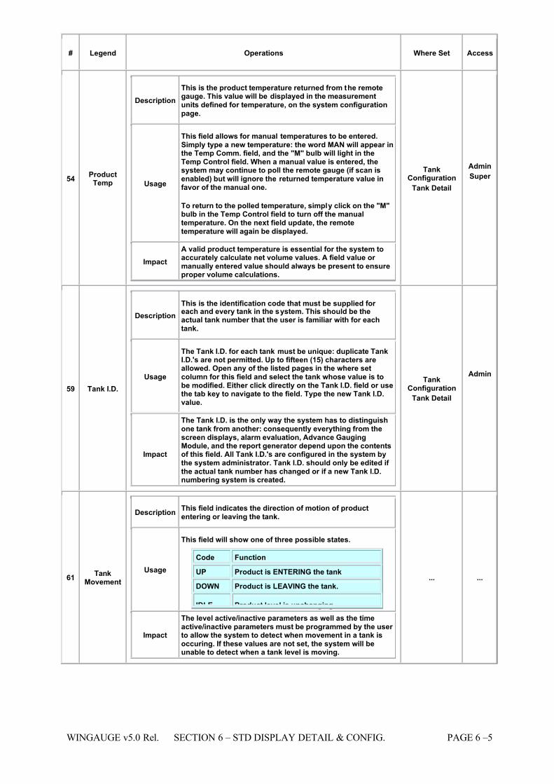
WINGAUGE v5.0 Rel. SECTION 6 – STD DISPLAY DETAIL & CONFIG. PAGE 6 –5
# Legend Operations Where Set Access
54 ProductTemp
Description This is the product temperature returned from the remotegauge. This value will be displayed in the measurementunits defined for temperature, on the system configurationpage.
Usage
This field allows for manual temperatures to be entered.Simply type a new temperature: the word MAN will appear inthe Temp Comm. field, and the "M" bulb will light in theTemp Control field. When a manual value is entered, thesystem may continue to poll the remote gauge (if scan isenabled) but will ignore the returned temperature value infavor of the manual one.
To return to the polled temperature, simply click on the "M"bulb in the Temp Control field to turn off the manualtemperature. On the next field update, the remotetemperature will again be displayed.
Impact A valid product temperature is essential for the system toaccurately calculate net volume values. A field value or manually entered value should always be present to ensureproper volume calculations.
TankConfiguration
Tank Detail
Admin
Super
59 Tank I.D.
Description This is the identification code that must be supplied for each and every tank in the system. This should be theactual tank number that the user is familiar with for eachtank.
Usage
The Tank I.D. for each tank must be unique: duplicate TankI.D.'s are not permitted. Up to fifteen (15) characters areallowed. Open any of the listed pages in the where setcolumn for this field and select the tank whose value is tobe modified. Either click directly on the Tank I.D. field or usethe tab key to navigate to the field. Type the new Tank I.D.value.
Impact
The Tank I.D. is the only way the system has to distinguishone tank from another: consequently everything from thescreen displays, alarm evaluation, Advance GaugingModule, and the report generator depend upon the contentsof this field. All Tank I.D.'s are configured in the system bythe system administrator. Tank I.D. should only be edited if the actual tank number has changed or if a new Tank I.D.numbering system is created.
TankConfiguration
Tank Detail
Admin
61 TankMovement
Description This field indicates the direction of motion of productentering or leaving the tank.
Usage
This field will show one of three possible states.
Code Function
UP Product is ENTERING the tank
DOWN Product is LEAVING the tank.
IDLE Product level is unchanging.
Impact
The level active/inactive parameters as well as the timeactive/inactive parameters must be programmed by the user to allow the system to detect when movement in a tank isoccuring. If these values are not set, the system will beunable to detect when a tank level is moving.
... ...
7/16/2019 3900 Manual
http://slidepdf.com/reader/full/3900-manual 54/266
PAGE 6 – 6 SECTION 6 – STD DISPLAY DETAIL & CONFIG. WINGAUGE v5.0 Rel.
Operational Restrictions:
NONE
See Also:
Tank Configuration
- Rate Interval
- Level Active/ Level Inactive
- Time Active/ Time Inactive
7/16/2019 3900 Manual
http://slidepdf.com/reader/full/3900-manual 55/266
WINGAUGE v5.0 Rel. SECTION 6 – STD DISPLAY DETAIL & CONFIG. PAGE 6 –7
ALARM HISTORY
Description:
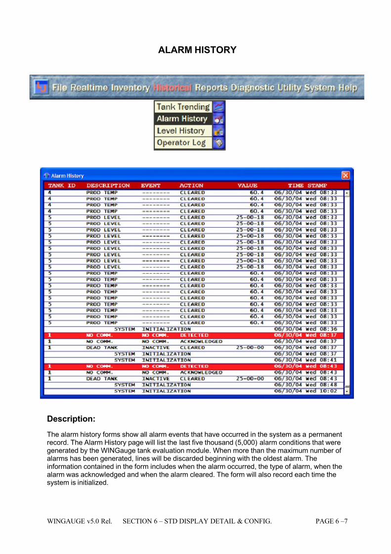
The alarm history forms show all alarm events that have occurred in the system as a permanentrecord. The Alarm History page will list the last five thousand (5,000) alarm conditions that weregenerated by the WINGauge tank evaluation module. When more than the maximum number of alarms has been generated, lines will be discarded beginning with the oldest alarm. Theinformation contained in the form includes when the alarm occurred, the type of alarm, when thealarm was acknowledged and when the alarm cleared. The form will also record each time thesystem is initialized.

7/16/2019 3900 Manual
http://slidepdf.com/reader/full/3900-manual 56/266
PAGE 6 – 8 SECTION 6 – STD DISPLAY DETAIL & CONFIG. WINGAUGE v5.0 Rel.
Operator Available Functions:
NONE, display only
Operational Restrictions:
NONE
See Also:
N/A
7/16/2019 3900 Manual
http://slidepdf.com/reader/full/3900-manual 57/266
WINGAUGE v5.0 Rel. SECTION 6 – STD DISPLAY DETAIL & CONFIG. PAGE 6 –9
ALARM SUMMARY
7/16/2019 3900 Manual
http://slidepdf.com/reader/full/3900-manual 58/266
PAGE 6 – 10 SECTION 6 – STD DISPLAY DETAIL & CONFIG. WINGAUGE v5.0 Rel.
Description:
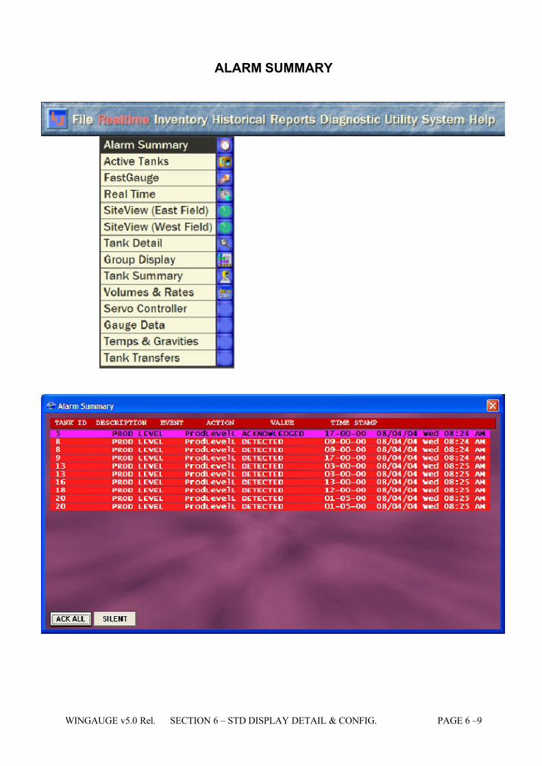
The Alarm Summary page will list all active alarm conditions, whether or not theyhave been acknowledged by the operator. Unacknowledged alarms will behighlighted in red, acknowledged alarms will be shown in the color defined by thesystem administrator for that alarm type (See Colors.INI in the Administrator Manual). The display automatically appears when a new alarm occurs. Thealarms appear in order from top to bottom based on the order in which they
occurred. Display is limited to 5000 alarms.
Operator Available Functions:
• Acknowledge: To acknowledge an alarm (and turn off any audio outputassociated with the condition) simply click on the detail for that alarm. Allalarms may be acknowledged by clicking on the ACK ALL button at thebottom of the window.
• Silence: The audio may be silenced without acknowledging any alarms byclicking on the SILENT button.
Restrictions to Operation:
None
See Also:
Tank Detail
Alarm Settings
7/16/2019 3900 Manual
http://slidepdf.com/reader/full/3900-manual 59/266
WINGAUGE v5.0 Rel. SECTION 6 – STD DISPLAY DETAIL & CONFIG. PAGE 6 –11
CONVERSION CALCULATOR
Description:
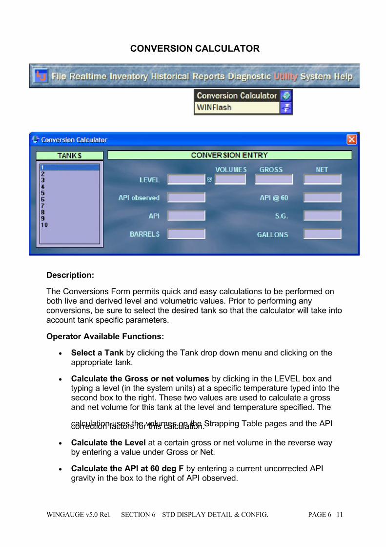
The Conversions Form permits quick and easy calculations to be performed onboth live and derived level and volumetric values. Prior to performing anyconversions, be sure to select the desired tank so that the calculator will take intoaccount tank specific parameters.
Operator Available Functions:
• Select a Tank by clicking the Tank drop down menu and clicking on theappropriate tank.
• Calculate the Gross or net volumes by clicking in the LEVEL box andtyping a level (in the system units) at a specific temperature typed into thesecond box to the right. These two values are used to calculate a grossand net volume for this tank at the level and temperature specified. The
calculation uses the volumes on the Strapping Table pages and the APIcorrection factors for this calculation.
• Calculate the Level at a certain gross or net volume in the reverse wayby entering a value under Gross or Net.
• Calculate the API at 60 deg F by entering a current uncorrected APIgravity in the box to the right of API observed.
7/16/2019 3900 Manual
http://slidepdf.com/reader/full/3900-manual 60/266
PAGE 6 – 12 SECTION 6 – STD DISPLAY DETAIL & CONFIG. WINGAUGE v5.0 Rel.
• Convert Specific Gravity to API gravity or visa-versa by entering the oneor the other value.
• Convert Barrels to Gallons or visa-versa by entering one or the other value.
Operational Restrictions: NONE
See Also:
N/A
7/16/2019 3900 Manual
http://slidepdf.com/reader/full/3900-manual 61/266
WINGAUGE v5.0 Rel. SECTION 6 – STD DISPLAY DETAIL & CONFIG. PAGE 6 –13
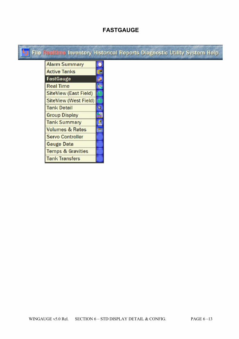
FASTGAUGE
7/16/2019 3900 Manual
http://slidepdf.com/reader/full/3900-manual 62/266
PAGE 6 – 14 SECTION 6 – STD DISPLAY DETAIL & CONFIG. WINGAUGE v5.0 Rel.
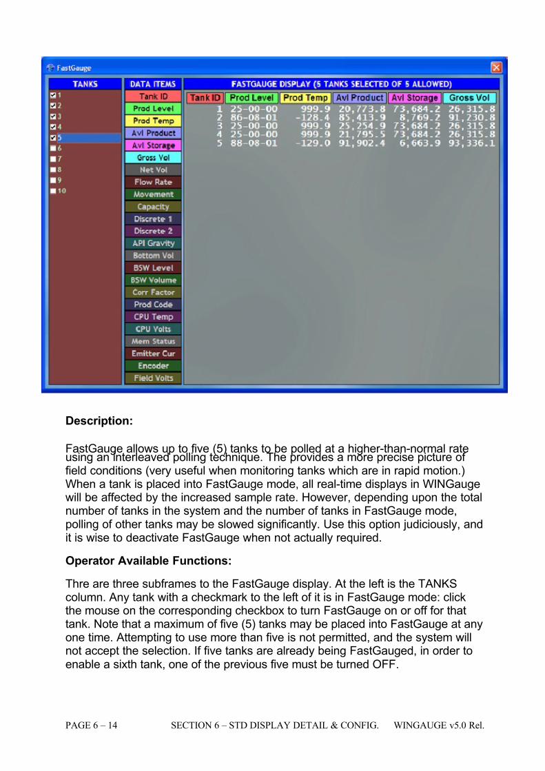
Description:
FastGauge allows up to five (5) tanks to be polled at a higher-than-normal rateusing an interleaved polling technique. The provides a more precise picture of field conditions (very useful when monitoring tanks which are in rapid motion.)When a tank is placed into FastGauge mode, all real-time displays in WINGaugewill be affected by the increased sample rate. However, depending upon the totalnumber of tanks in the system and the number of tanks in FastGauge mode,polling of other tanks may be slowed significantly. Use this option judiciously, andit is wise to deactivate FastGauge when not actually required.
Operator Available Functions:
Thre are three subframes to the FastGauge display. At the left is the TANKScolumn. Any tank with a checkmark to the left of it is in FastGauge mode: clickthe mouse on the corresponding checkbox to turn FastGauge on or off for thattank. Note that a maximum of five (5) tanks may be placed into FastGauge at anyone time. Attempting to use more than five is not permitted, and the system willnot accept the selection. If five tanks are already being FastGauged, in order toenable a sixth tank, one of the previous five must be turned OFF.
7/16/2019 3900 Manual
http://slidepdf.com/reader/full/3900-manual 63/266
WINGAUGE v5.0 Rel. SECTION 6 – STD DISPLAY DETAIL & CONFIG. PAGE 6 –15
The next frame is the DATA ITEMS column. This works identically to the DATAITEMS column in the Level History and Trending displays: simply click on thedesired item to toggle it on or off. In the example shown above, the data itemsTank ID, Prod Level, Prod Temp, Avl Product, Avl Storage and Gross Vol areselected.
The third frame is the FASTGAUGE DISPLAY. Notice that there is a matchingcolor-coded column of data for each item selected in the DATA ITEMS column. If more columns are selected than will fit in the frame, the mouse may be used tore-size the window to accommodate the additional fields Note also that the titlefor this frame shows the number of tanks currently on FastGauge, and the totalnumber that are allowed.
Operational Restrictions:
None
See Also:
None
7/16/2019 3900 Manual
http://slidepdf.com/reader/full/3900-manual 64/266
PAGE 6 – 16 SECTION 6 – STD DISPLAY DETAIL & CONFIG. WINGAUGE v5.0 Rel.
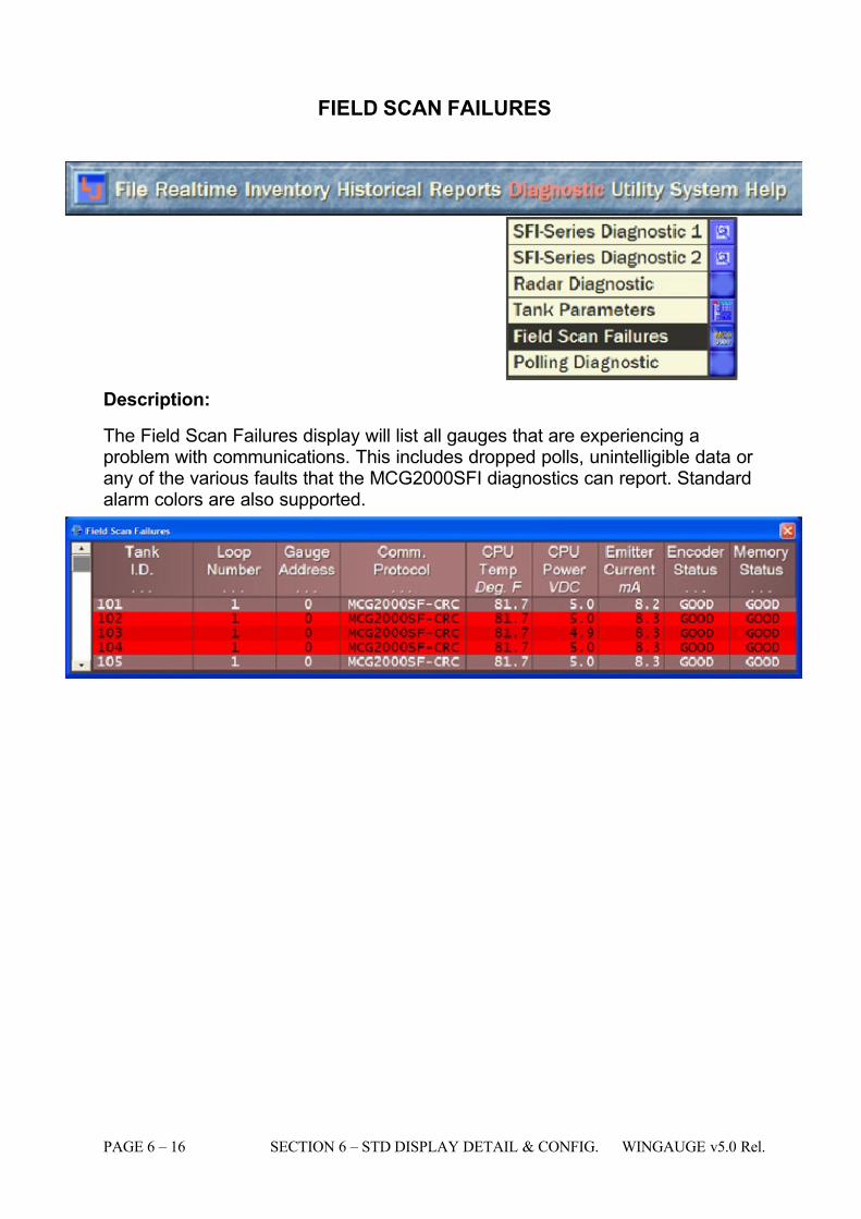
FIELD SCAN FAILURES
Description:
The Field Scan Failures display will list all gauges that are experiencing aproblem with communications. This includes dropped polls, unintelligible data or any of the various faults that the MCG2000SFI diagnostics can report. Standardalarm colors are also supported.
7/16/2019 3900 Manual
http://slidepdf.com/reader/full/3900-manual 65/266
WINGAUGE v5.0 Rel. SECTION 6 – STD DISPLAY DETAIL & CONFIG. PAGE 6 –17
Operator Available Functions:
Operational Restrictions:
# Legend Operations Where Set Access
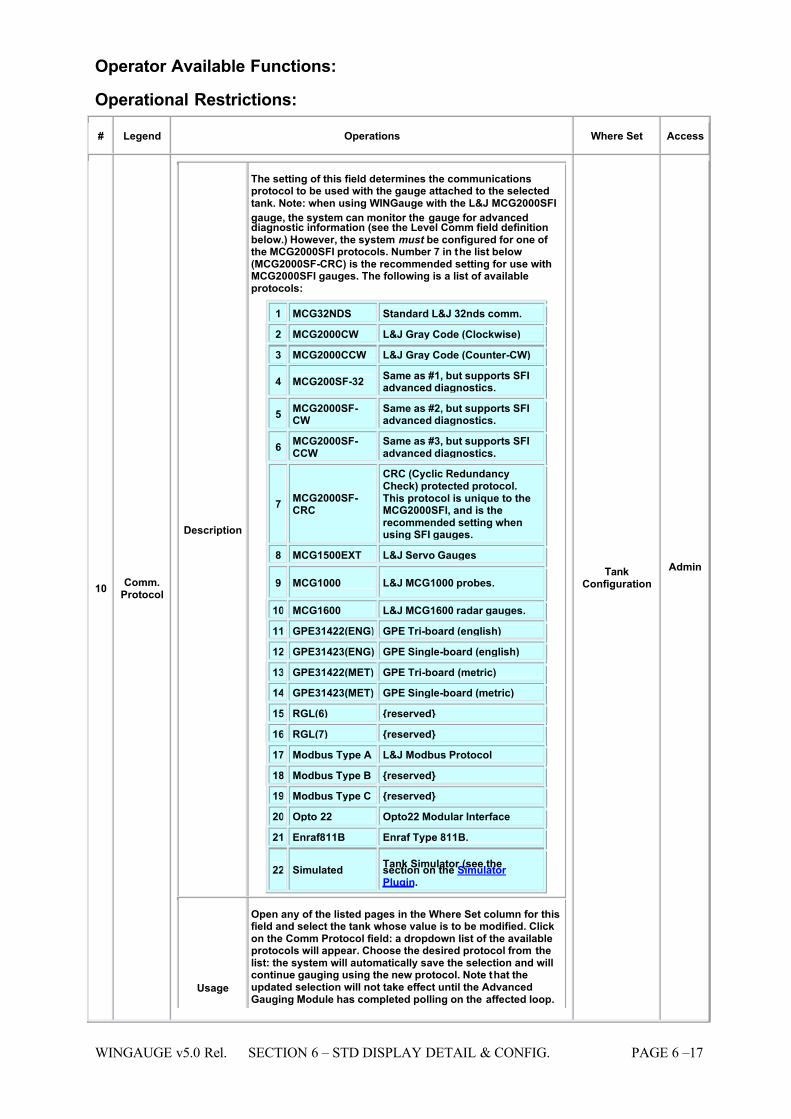
10 Comm.Protocol
Description
The setting of this field determines the communicationsprotocol to be used with the gauge attached to the selectedtank. Note: when using WINGauge with the L&J MCG2000SFI
gauge, the system can monitor the gauge for advanceddiagnostic information (see the Level Comm field definitionbelow.) However, the system must be configured for one of the MCG2000SFI protocols. Number 7 in the list below(MCG2000SF-CRC) is the recommended setting for use withMCG2000SFI gauges. The following is a list of availableprotocols:
1 MCG32NDS Standard L&J 32nds comm.
2 MCG2000CW L&J Gray Code (Clockwise)
3 MCG2000CCW L&J Gray Code (Counter-CW)
4 MCG200SF-32 Same as #1, but supports SFIadvanced diagnostics.
5 MCG2000SF-CW
Same as #2, but supports SFIadvanced diagnostics.
6 MCG2000SF-CCW
Same as #3, but supports SFIadvanced diagnostics.
7 MCG2000SF-CRC
CRC (Cyclic RedundancyCheck) protected protocol.This protocol is unique to theMCG2000SFI, and is therecommended setting whenusing SFI gauges.
8 MCG1500EXT L&J Servo Gauges
9 MCG1000 L&J MCG1000 probes.
10 MCG1600 L&J MCG1600 radar gauges.
11 GPE31422(ENG) GPE Tri-board (english)
12 GPE31423(ENG) GPE Single-board (english)
13 GPE31422(MET) GPE Tri-board (metric)
14 GPE31423(MET) GPE Single-board (metric)
15 RGL(6) {reserved}
16 RGL(7) {reserved}
17 Modbus Type A L&J Modbus Protocol
18 Modbus Type B {reserved}
19 Modbus Type C {reserved}
20 Opto 22 Opto22 Modular Interface
21 Enraf811B Enraf Type 811B.
22 Simulated Tank Simulator (see thesection on the Simulator Plugin.
Usage
Open any of the listed pages in the Where Set column for thisfield and select the tank whose value is to be modified. Clickon the Comm Protocol field: a dropdown list of the availableprotocols will appear. Choose the desired protocol from thelist: the system will automatically save the selection and willcontinue gauging using the new protocol. Note that theupdated selection will not take effect until the AdvancedGauging Module has completed polling on the affected loop.
TankConfiguration
Admin
7/16/2019 3900 Manual
http://slidepdf.com/reader/full/3900-manual 66/266
PAGE 6 – 18 SECTION 6 – STD DISPLAY DETAIL & CONFIG. WINGAUGE v5.0 Rel.
# Legend Operations Where Set Access
For all L&J SFI series field devices, the protocol can be set toa variety of different styles. Verify the programming of the SFITransmitter to ensure the comm. protocol is programmed asdesired.
Impact
Many gauges support multiple protocols, and valid data willnot be received if WINGauge and the gauge are configured for incompatible protocols. The correct comm. protocol will
normally be programmed by L&J prior to shipment of thesystem. It is imperative that the proper Comm. protocol beselected to match the field device protocol. If it is not,incorrect or no data at all will result for level and temperatureinformation. If the user cannot find the proper communicationprotocol in the provided list of the gauging program, theyshould consult L&J Technical support before attempting anysystem configuration.
12 CPUPower
Description
MCG200SFI-only: This is the regulated power supply voltagebeing applied to the CPU board in the remote gauge.Nominally 5 volts DC, any significant change in this valuemay indicate a problem with the CPU's power source or theon-board voltage regulator.
Usage This is a display-only field and cannot be edited.
... ...
13 CPUTemp
Description MCG2000SFI-only: this value is the internal ambienttemperature of the gauge electronics package as measuredfrom a thermal sensor mounted on the CPU board.
Usage This is a display-only field and cannot be edited.
... ...
20 Emitter Current
Description MCG2000SFI-only: The current flow (measured inmilliamperes) that is being drawn by the gauge's emitter array. This value is returned from the MCG2000SFI leveltransmitter when the Comm. Protocol is set to 2000SFI type.
Usage This is a display-only field and cannot be edited.
Impact The displayed value will allow the user to continuouslymonitor the MCG2000SFI level transmitter for proper operation of the optical encoder.
... ...
7/16/2019 3900 Manual
http://slidepdf.com/reader/full/3900-manual 67/266
WINGAUGE v5.0 Rel. SECTION 6 – STD DISPLAY DETAIL & CONFIG. PAGE 6 –19
# Legend Operations Where Set Access
22 Encoder Status
Description
MCG2000SFI-only: This field displays the status of the rotaryshaft encoder mechanism. The following codes may appear inthis field:
GOOD Communication has been successfullyestablished with the remote device, and noerrors have been detected.
AMB
MCG200SFI-only: An Ambiguity Error hasoccurred. This condition occurs when thegauge has detected an excessive change inlevel. This typically happens when theencoder wheel's emitter or receiver hasmalfunctioned, or there is some other problem with the optics.
CA
MCG200SFI-only: A Cable Fault has beendetected. This indicates that there is virtuallyno emitter current (generally this occurswhen the cable leading from the CPU boardto the encoder module has been unplugged.)
ECL MCG200SFI-only: The emitter current hasdropped below the factory-programmedminimum value.
ECH MCG200SFI-only: The emitter current hasexceeded the factory-programmed maximumvalue.
ERR A undetermined error has occurred. Pleasereport this to L&J Technical support.
This value is returned from the MCG2000SFI level transmitter when comm. protocol is set to 2000SFI type.
Usage This is a display-only field and cannot be edited.
Impact The displayed value will allow the user to continuouslymonitor the MCG2000SFI level transmitter for proper operation of the optical encoder.
... ...
23 FieldPower
Description
MCG2000SFI-only: this displays the field voltage available atthe gauge. This is particularly useful for diagnosing remotewiring faults. This value is returned from the MCG2000SFIlevel transmitter when comm. protocol is set to 2000SFI type.This is the amount of field voltage measured by the 2000SFIlevel transmitter that is being received from the central roompower source.
Usage This is a display-only field and cannot be edited.
Impact The displayed value for field power will allow the user tomonitor field power at all tanks that are using theMCG2000SFI level transmitter.
... ...
25 GaugeAddress Description
This field is where the numeric address of the remote gaugeis entered into WINGauge. Each field device connected tosame part on the gauging system must have it's own uniquegauge address. This will allow the gauging program toidentify each tank and it's corresponding level andtemperature. Consult the users manual of the leveltransmitter in use to determine the proper procedure for setting gauge address. Whenever possibble, it is advisable toset the gauge address to match as close as possible to thetank number. For example, Tank 1 set to address 1, Tank 2 toaddress 2, etc.
TankConfiguration
Admin
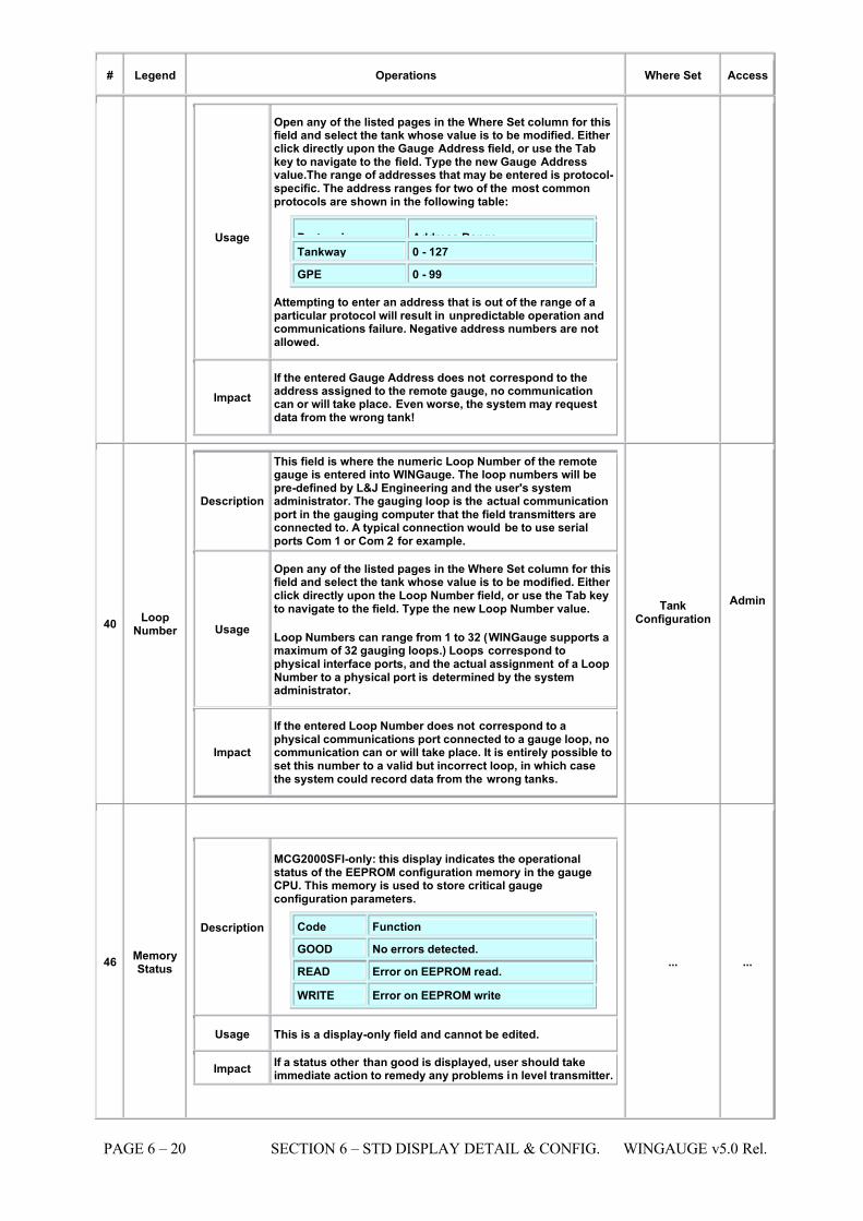
7/16/2019 3900 Manual
http://slidepdf.com/reader/full/3900-manual 68/266
PAGE 6 – 20 SECTION 6 – STD DISPLAY DETAIL & CONFIG. WINGAUGE v5.0 Rel.
# Legend Operations Where Set Access
Usage
Open any of the listed pages in the Where Set column for thisfield and select the tank whose value is to be modified. Either click directly upon the Gauge Address field, or use the Tabkey to navigate to the field. Type the new Gauge Addressvalue.The range of addresses that may be entered is protocol-specific. The address ranges for two of the most commonprotocols are shown in the following table:
Protocol Address Range Tankway 0 - 127
GPE 0 - 99
Attempting to enter an address that is out of the range of aparticular protocol will result in unpredictable operation andcommunications failure. Negative address numbers are notallowed.
Impact If the entered Gauge Address does not correspond to theaddress assigned to the remote gauge, no communicationcan or will take place. Even worse, the system may requestdata from the wrong tank!
40 LoopNumber
Description
This field is where the numeric Loop Number of the remotegauge is entered into WINGauge. The loop numbers will bepre-defined by L&J Engineering and the user's systemadministrator. The gauging loop is the actual communicationport in the gauging computer that the field transmitters areconnected to. A typical connection would be to use serialports Com 1 or Com 2 for example.
Usage
Open any of the listed pages in the Where Set column for thisfield and select the tank whose value is to be modified. Either click directly upon the Loop Number field, or use the Tab keyto navigate to the field. Type the new Loop Number value.
Loop Numbers can range from 1 to 32 (WINGauge supports amaximum of 32 gauging loops.) Loops correspond tophysical interface ports, and the actual assignment of a LoopNumber to a physical port is determined by the systemadministrator.
Impact
If the entered Loop Number does not correspond to aphysical communications port connected to a gauge loop, nocommunication can or will take place. It is entirely possible toset this number to a valid but incorrect loop, in which casethe system could record data from the wrong tanks.
TankConfiguration
Admin
46 MemoryStatus
Description
MCG2000SFI-only: this display indicates the operationalstatus of the EEPROM configuration memory in the gaugeCPU. This memory is used to store critical gaugeconfiguration parameters.
Code Function
GOOD No errors detected.
READ Error on EEPROM read.
WRITE Error on EEPROM write
Usage This is a display-only field and cannot be edited.
Impact If a status other than good is displayed, user should takeimmediate action to remedy any problems in level transmitter.
... ...
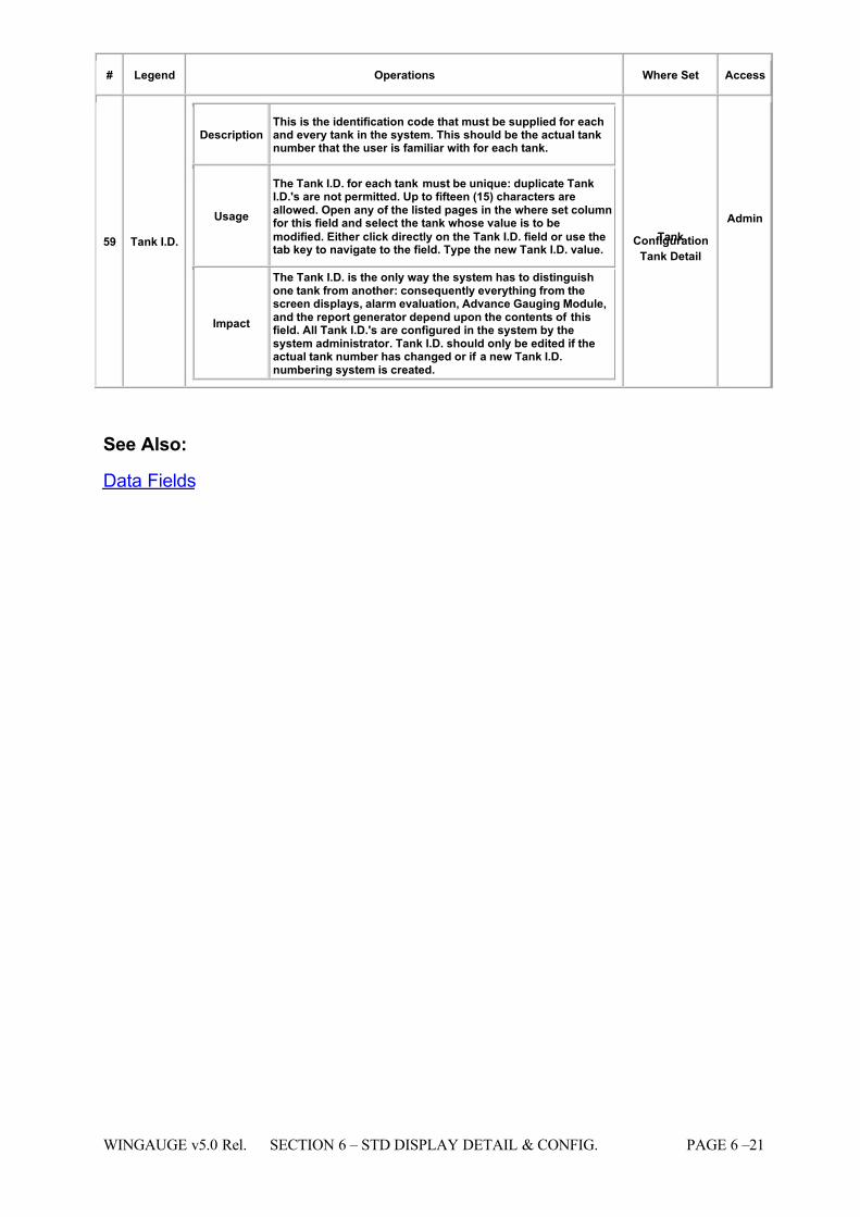
7/16/2019 3900 Manual
http://slidepdf.com/reader/full/3900-manual 69/266
WINGAUGE v5.0 Rel. SECTION 6 – STD DISPLAY DETAIL & CONFIG. PAGE 6 –21
# Legend Operations Where Set Access
59 Tank I.D.
Description This is the identification code that must be supplied for eachand every tank in the system. This should be the actual tanknumber that the user is familiar with for each tank.
Usage
The Tank I.D. for each tank must be unique: duplicate TankI.D.'s are not permitted. Up to fifteen (15) characters areallowed. Open any of the listed pages in the where set columnfor this field and select the tank whose value is to be
modified. Either click directly on the Tank I.D. field or use thetab key to navigate to the field. Type the new Tank I.D. value.
Impact
The Tank I.D. is the only way the system has to distinguishone tank from another: consequently everything from thescreen displays, alarm evaluation, Advance Gauging Module,and the report generator depend upon the contents of thisfield. All Tank I.D.'s are configured in the system by thesystem administrator. Tank I.D. should only be edited if theactual tank number has changed or if a new Tank I.D.numbering system is created.
TankConfiguration Tank Detail
Admin
See Also:
Data Fields
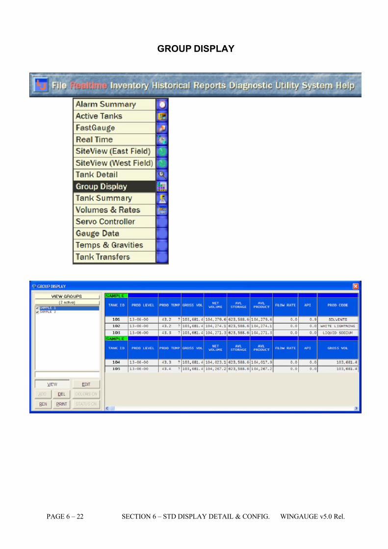
7/16/2019 3900 Manual
http://slidepdf.com/reader/full/3900-manual 70/266
PAGE 6 – 22 SECTION 6 – STD DISPLAY DETAIL & CONFIG. WINGAUGE v5.0 Rel.
GROUP DISPLAY
7/16/2019 3900 Manual
http://slidepdf.com/reader/full/3900-manual 71/266
WINGAUGE v5.0 Rel. SECTION 6 – STD DISPLAY DETAIL & CONFIG. PAGE 6 –23
Description:
This flexible, spreadsheet-like real-time display presents detailed tankinformation, organized into arbitrary user-defined "groups". Each group maycontain information on any number of installed tanks (limited only by systemresources), and the actual data presented may be customized on a per-group
basis. Up to one hundred such groups can be created, and may be convenientlymodified or removed at any time. Tank groups are used only for the purpose of displaying numeric data, and have no effect upon data collection activities.
CREATING TANK GROUPS
This form has two operating modes: View, and Edit. The system normallydefaults to View mode when the Group Display is first loaded. If this is the firsttime the WinGauge system has been used, there will be no defined groups, sothe display will be blank. Group creation is simplicity itself: just type the desiredname into the entry field (directly above the VIEW and EDIT command buttons)and click the ADD command button. For example, click the mouse inside the
entry field and type "MY TANKS". Then click the ADD command button (or pressthe Enter key) to create a new group named "MY TANKS", which willimmediately appear in the VIEW GROUPS list box.
Notice the small selection box to the left of "MY TANKS". Single-click the box: acheckmark will appear indicating that this group has been selected for display,and the status line will change from none active to 1 active. However, as group"MY TANKS" currently has no tanks actually assigned to it, the data display willremain blank. Click the EDIT command button.
If Edit mode was successfully entered, VIEW GROUPS will change to EDIT
GROUP, as shown above, and the status line will show the name of the groupselected (in this case, "MY TANKS".) The list below the status line (which in Viewmode contains the list of groups) will now show the list of all available tank ID's.This only includes tanks that are defined as "IN USE" on the SystemConfiguration Tank Configuration tab. Use the standard checkboxes to determinewhich particular tanks should be enabled for display in this group. If checked, thecorresponding tank's information will be displayed in View mode. If leftunchecked, the data will not be displayed.
For this example, select the top two tanks for display. In the data area to theright, there should now be spreadsheet-style data display. Across the top thecolumn headers indicate the type of gauge data contained within each column:
the leftmost column indicates the physical tanks assigned to this group. The dataitems automatically selected for new groups are as follows:
TANK I.D.
PROD LEVEL
PROD TEMP
GROSS VOL
7/16/2019 3900 Manual
http://slidepdf.com/reader/full/3900-manual 72/266
PAGE 6 – 24 SECTION 6 – STD DISPLAY DETAIL & CONFIG. WINGAUGE v5.0 Rel.
NET VOLUME
AVL STORAGE
AVL PRODUCT
RATE CALC
API
However, the system is not limited to displaying only those items. To change thedata item selection for any column, click on the column header. A pull-down listwill appear, containing the following options:
[REMOVE]
Tank Id
Prod Level
Prod Temp
Gross Vol
Net Volume
Avl Storage
Avl Product
Rate Calc
Api
Density
Bsw Level
Bsw
Volume
Gr_pr
Name
Hi Hi Level
High Level
Lolo Level
Low Level
Critical Time (see the section on the Tank Detail page for more info) ProductCode Group Code
7/16/2019 3900 Manual
http://slidepdf.com/reader/full/3900-manual 73/266
WINGAUGE v5.0 Rel. SECTION 6 – STD DISPLAY DETAIL & CONFIG. PAGE 6 –25
Use the mouse pointer to select the new data item that should be displayed inthe selected column. The entire column will be instantly updated to reflect thechange. To blank a column, select [REMOVE]. Up to seventeen (17) columnsmay be defined at any time for a particular group, and the same data item maybe displayed in more than one column simultaneously. Each group may have itsown unique set of data items.
To complete the edit process and return to View mode, click the VIEW command
button. The display will return to viewing live data. The data area now shows thegroup name directly above the column headers: as more groups are added theycan be easily distinguished from each other. If more groups are defined than canfit in the window (a likely occurrence), standard scroll bars will appear on theright. The display is updated at regular intervals according to the MCG3900'sinternal refresh rate.
To save the current state of the Group List display, close the window using theClose gadget in the upper right hand corner of the window. If you simply exit theWinGauge program your changes will not be saved.
EDITING GROUPS
Existing tank groups may be edited in much the same manner. When in Viewmode, click on the name of the tank group to be edited, then click the EDITcommand button. Make any required modifications to the group's settings asdescribed above, then click the VIEW button to return to the live multi-groupdisplay.
Notice the two command buttons beneath the EDIT button, labeled COLORS ONand STATUS ON in the preceding example. Each group has maintains its ownsettings for these two options. COLORS ON determines whether WINGaugealarm colors will be applied to each detail line in the group display (just like the
Tank Summary shows alarm colors). The STATUS ON button chooses whether the standard communications status codes will be suffixed to the live gauge fieldsProd Level, Prod Temp and BS&W. These are the same codes that appear in thecorresponding fields in the Tank Detail and Tank Configuration pages. Whenclicked, the legend in each button will toggle to show the current setting.COLORS ON will toggle to NO COLORS, and STATUS ON will toggle to NOSTATUS.
If a particular display column has already been selected as a volume data item(i.e. Gross Vol, Net Volume, Avl Storage, and Avl Product) the pull-down listdescribed above will have three additional options in it if the column header isclicked again. They are as follows:
[SYSTEM]
Display using standard format defined on the System Configuration page.
[nnnnnnn]
Display with NO digits to the right of the decimal point.
[nnnnnnn.0].
7/16/2019 3900 Manual
http://slidepdf.com/reader/full/3900-manual 74/266
PAGE 6 – 26 SECTION 6 – STD DISPLAY DETAIL & CONFIG. WINGAUGE v5.0 Rel.
Display with 1 digit to the right of the decimal point.
DELETING GROUPS
Deleting a tank group requires only two mouse clicks. Click the name of thegroup to be removed, and then click the DEL command button. A last-chance"Are you sure?" window will appear. To abort the delete and leave the groupuntouched, click the green NO button. To delete the group, click the red YESbutton, and the group will disappear without a trace. Groups thus deleted cannotbe recovered.
RENAMING GROUPS
Changing the display name of an existing group is also very straightforward.Click on the name of the group to be renamed, and type the new name into theentry field directly above the VIEW and EDIT command buttons. Click the RENbutton and the new name will be applied to the group list.
Operator Available Functions:
ALL
See Also:
N/A
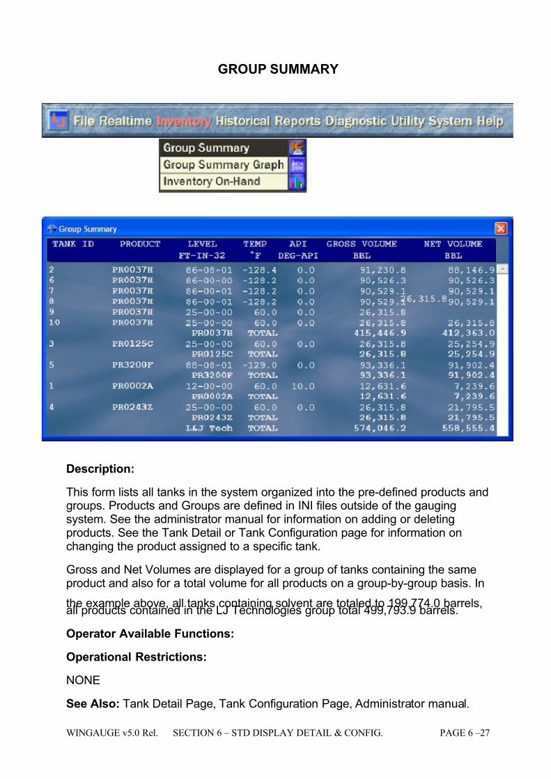
7/16/2019 3900 Manual
http://slidepdf.com/reader/full/3900-manual 75/266
WINGAUGE v5.0 Rel. SECTION 6 – STD DISPLAY DETAIL & CONFIG. PAGE 6 –27
GROUP SUMMARY
Description:
This form lists all tanks in the system organized into the pre-defined products andgroups. Products and Groups are defined in INI files outside of the gaugingsystem. See the administrator manual for information on adding or deletingproducts. See the Tank Detail or Tank Configuration page for information onchanging the product assigned to a specific tank.
Gross and Net Volumes are displayed for a group of tanks containing the sameproduct and also for a total volume for all products on a group-by-group basis. In
the example above, all tanks containing solvent are totaled to 199,774.0 barrels,all products contained in the LJ Technologies group total 499,793.9 barrels.
Operator Available Functions:
Operational Restrictions:
NONE
See Also: Tank Detail Page, Tank Configuration Page, Administrator manual.
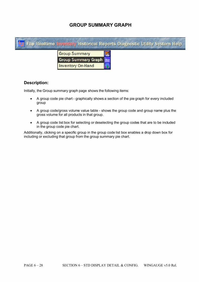
7/16/2019 3900 Manual
http://slidepdf.com/reader/full/3900-manual 76/266
PAGE 6 – 28 SECTION 6 – STD DISPLAY DETAIL & CONFIG. WINGAUGE v5.0 Rel.
GROUP SUMMARY GRAPH
Description:
Initially, the Group summary graph page shows the following items:
• A group code pie chart - graphically shows a section of the pie graph for every includedgroup
• A group code/gross volume value table - shows the group code and group name plus thegross volume for all products in that group.
• A group code list box for selecting or deselecting the group codes that are to be includedin the group code pie chart.
Additionally, clicking on a specific group in the group code list box enables a drop down box for including or excluding that group from the group summary pie chart.
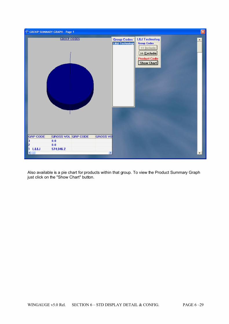
7/16/2019 3900 Manual
http://slidepdf.com/reader/full/3900-manual 77/266
WINGAUGE v5.0 Rel. SECTION 6 – STD DISPLAY DETAIL & CONFIG. PAGE 6 –29
Also available is a pie chart for products within that group. To view the Product Summary Graph just click on the "Show Chart" button.
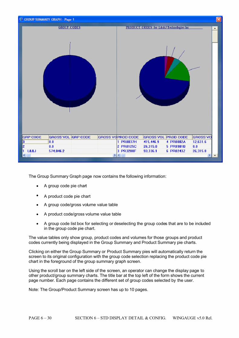
7/16/2019 3900 Manual
http://slidepdf.com/reader/full/3900-manual 78/266
PAGE 6 – 30 SECTION 6 – STD DISPLAY DETAIL & CONFIG. WINGAUGE v5.0 Rel.
The Group Summary Graph page now contains the following information:
• A group code pie chart
• A product code pie chart
• A group code/gross volume value table
• A product code/gross volume value table
• A group code list box for selecting or deselecting the group codes that are to be includedin the group code pie chart.
The value tables only show group, product codes and volumes for those groups and productcodes currently being displayed in the Group Summary and Product Summary pie charts.
Clicking on either the Group Summary or Product Summary pies will automatically return thescreen to its original configuration with the group code selection replacing the product code piechart in the foreground of the group summary graph screen.
Using the scroll bar on the left side of the screen, an operator can change the display page toother product/group summary charts. The title bar at the top left of the form shows the currentpage number. Each page contains the different set of group codes selected by the user.
Note: The Group/Product Summary screen has up to 10 pages.
7/16/2019 3900 Manual
http://slidepdf.com/reader/full/3900-manual 79/266
WINGAUGE v5.0 Rel. SECTION 6 – STD DISPLAY DETAIL & CONFIG. PAGE 6 –31
Operator Available Functions:
NONE
Operational Restrictions:
NONE
See Also:
N/A
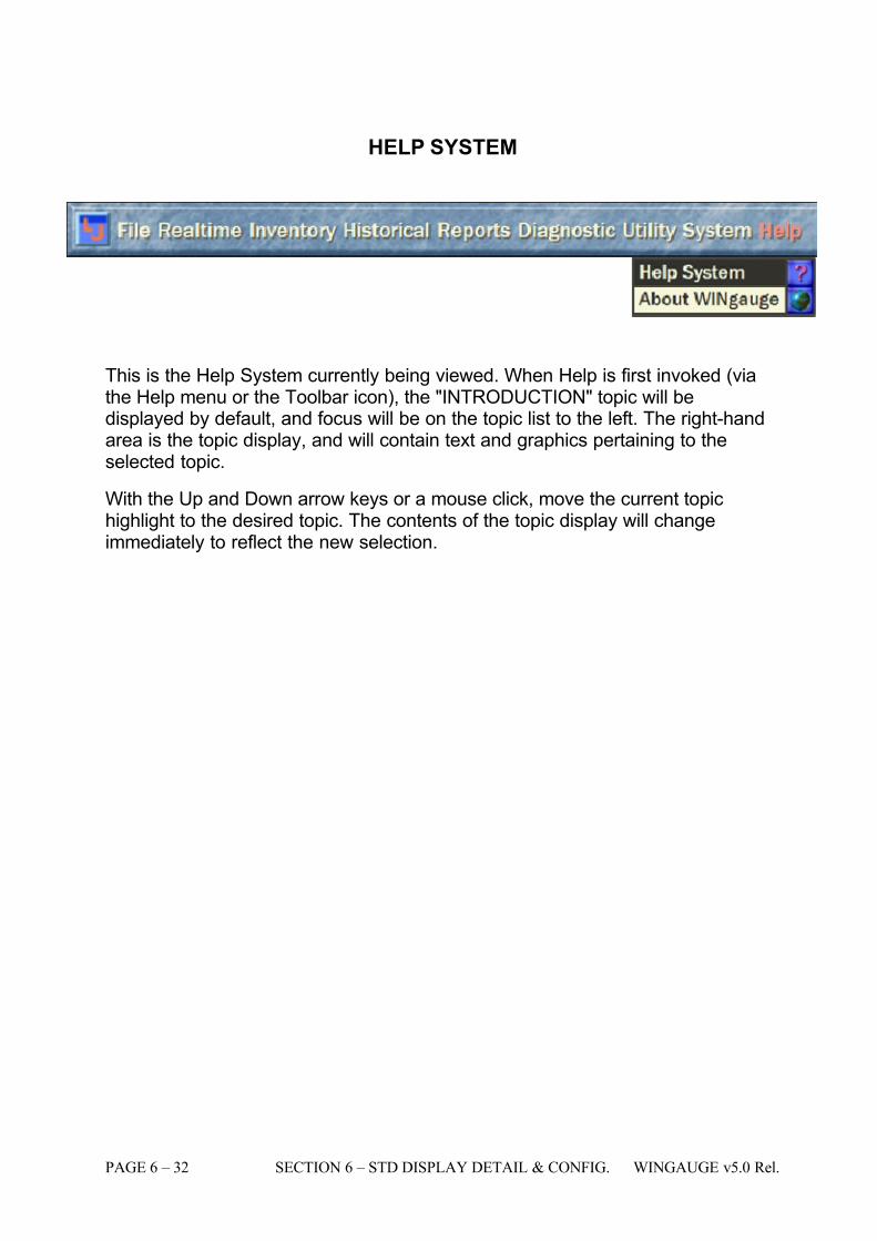
7/16/2019 3900 Manual
http://slidepdf.com/reader/full/3900-manual 80/266
PAGE 6 – 32 SECTION 6 – STD DISPLAY DETAIL & CONFIG. WINGAUGE v5.0 Rel.
HELP SYSTEM
This is the Help System currently being viewed. When Help is first invoked (viathe Help menu or the Toolbar icon), the "INTRODUCTION" topic will bedisplayed by default, and focus will be on the topic list to the left. The right-handarea is the topic display, and will contain text and graphics pertaining to theselected topic.
With the Up and Down arrow keys or a mouse click, move the current topichighlight to the desired topic. The contents of the topic display will changeimmediately to reflect the new selection.
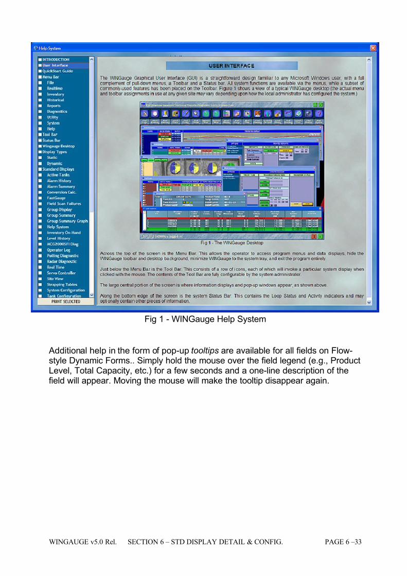
7/16/2019 3900 Manual
http://slidepdf.com/reader/full/3900-manual 81/266
WINGAUGE v5.0 Rel. SECTION 6 – STD DISPLAY DETAIL & CONFIG. PAGE 6 –33
Fig 1 - WINGauge Help System
Additional help in the form of pop-up tooltips are available for all fields on Flow-style Dynamic Forms.. Simply hold the mouse over the field legend (e.g., ProductLevel, Total Capacity, etc.) for a few seconds and a one-line description of thefield will appear. Moving the mouse will make the tooltip disappear again.
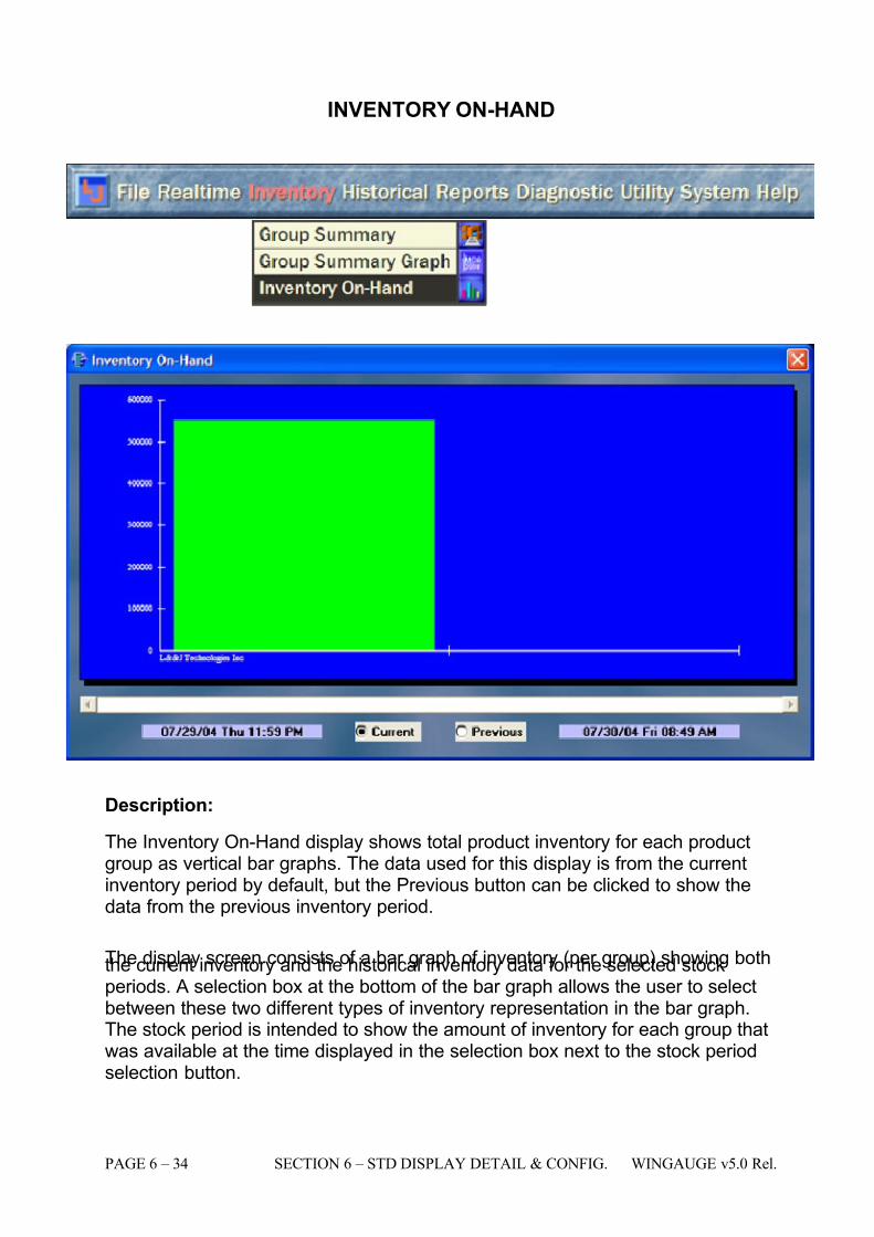
7/16/2019 3900 Manual
http://slidepdf.com/reader/full/3900-manual 82/266
PAGE 6 – 34 SECTION 6 – STD DISPLAY DETAIL & CONFIG. WINGAUGE v5.0 Rel.
INVENTORY ON-HAND
Description:
The Inventory On-Hand display shows total product inventory for each productgroup as vertical bar graphs. The data used for this display is from the currentinventory period by default, but the Previous button can be clicked to show thedata from the previous inventory period.
The display screen consists of a bar graph of inventory (per group) showing boththe current inventory and the historical inventory data for the selected stockperiods. A selection box at the bottom of the bar graph allows the user to selectbetween these two different types of inventory representation in the bar graph.The stock period is intended to show the amount of inventory for each group thatwas available at the time displayed in the selection box next to the stock periodselection button.
7/16/2019 3900 Manual
http://slidepdf.com/reader/full/3900-manual 83/266
WINGAUGE v5.0 Rel. SECTION 6 – STD DISPLAY DETAIL & CONFIG. PAGE 6 –35
This view is useful because relative differences in product quantities are easilyseen. If there are more groups than will fit in the window, the horizontal scroll bar at the bottom will be come active.
When the "Previous" option is activated, the left graph bar represents inventoryat 24 hours previous to the last inventory period (which is graphed in the rightbar). When the "Current" option is activated, the left graph bar representsinventory period and the right graph bar represents the current time inventory
value.
Groups having zero volumes for both periods will not appear on this display.
Operator Available Functions:
NONE
Operational Restrictions:
NONE
See Also:
N/A
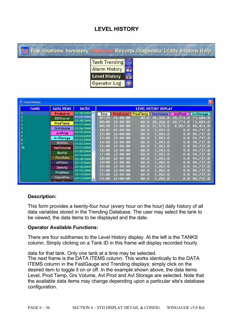
7/16/2019 3900 Manual
http://slidepdf.com/reader/full/3900-manual 84/266
PAGE 6 – 36 SECTION 6 – STD DISPLAY DETAIL & CONFIG. WINGAUGE v5.0 Rel.
LEVEL HISTORY
Description:
This form provides a twenty-four hour (every hour on the hour) daily history of alldata variables stored in the Trending Database. The user may select the tank tobe viewed, the data items to be displayed and the date.
Operator Available Functions:
There are four subframes to the Level History display. At the left is the TANKScolumn. Simply clicking on a Tank ID in this frame will display recorded hourly
data for that tank. Only one tank at a time may be selected. The next frame is the DATA ITEMS column. This works identically to the DATAITEMS column in the FastGauge and Trending displays: simply click on thedesired item to toggle it on or off. In the example shown above, the data itemsLevel, Prod Temp, Grs Volume, Avl Prod and Avl Storage are selected. Note thatthe available data items may change depending upon a particular site's databaseconfiguration.
7/16/2019 3900 Manual
http://slidepdf.com/reader/full/3900-manual 85/266
WINGAUGE v5.0 Rel. SECTION 6 – STD DISPLAY DETAIL & CONFIG. PAGE 6 –37
The third frame is the DATES display. This shows every single day from thecurrent date (always at the top) to the oldest date recorded in the database.Simply click on a date to select that date for display (use the scrollbar to accessdates that are not visible.)
The fourth frame is the LEVEL HISTORY DISPLAY. Notice that there is amatching color-coded column of data for each item selected in the DATA ITEMScolumn. If more columns are selected than will fit in the frame, the mouse may be
used to re-size the window to accommodate the additional fields. The rows of data in this display are organized by hour , and if no data was recorded on thehour, the nearest data point will be used instead. Notice in the example that theTIME column has several times that are not integral: 7:25, 9:20, 10:05 and 12:40.The system did, however, locate the closest time period where valid data wasrecorded, and displayed it instead.
Operational Restrictions:
None
See Also:
None
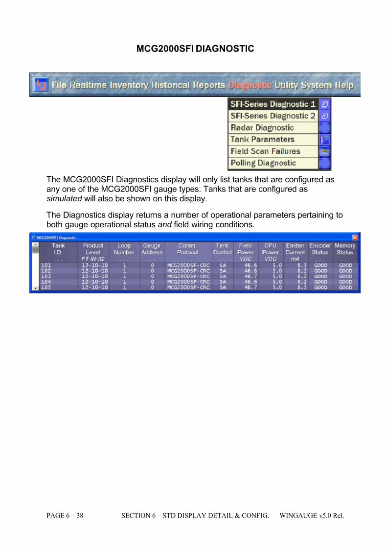
7/16/2019 3900 Manual
http://slidepdf.com/reader/full/3900-manual 86/266
PAGE 6 – 38 SECTION 6 – STD DISPLAY DETAIL & CONFIG. WINGAUGE v5.0 Rel.
MCG2000SFI DIAGNOSTIC
The MCG2000SFI Diagnostics display will only list tanks that are configured asany one of the MCG2000SFI gauge types. Tanks that are configured assimulated will also be shown on this display.
The Diagnostics display returns a number of operational parameters pertaining toboth gauge operational status and field wiring conditions.
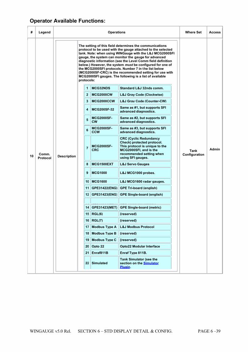
7/16/2019 3900 Manual
http://slidepdf.com/reader/full/3900-manual 87/266
WINGAUGE v5.0 Rel. SECTION 6 – STD DISPLAY DETAIL & CONFIG. PAGE 6 –39
Operator Available Functions:
# Legend Operations Where Set Access
10 Comm.Protocol Description
The setting of this field determines the communicationsprotocol to be used with the gauge attached to the selectedtank. Note: when using WINGauge with the L&J MCG2000SFIgauge, the system can monitor the gauge for advanceddiagnostic information (see the Level Comm field definitionbelow.) However, the system must be configured for one of the MCG2000SFI protocols. Number 7 in the list below(MCG2000SF-CRC) is the recommended setting for use withMCG2000SFI gauges. The following is a list of availableprotocols:
1 MCG32NDS Standard L&J 32nds comm.
2 MCG2000CW L&J Gray Code (Clockwise)
3 MCG2000CCW L&J Gray Code (Counter-CW)
4 MCG200SF-32 Same as #1, but supports SFIadvanced diagnostics.
5 MCG2000SF-CW
Same as #2, but supports SFIadvanced diagnostics.
6 MCG2000SF-CCW
Same as #3, but supports SFIadvanced diagnostics.
7 MCG2000SF-CRC
CRC (Cyclic RedundancyCheck) protected protocol.This protocol is unique to theMCG2000SFI, and is therecommended setting whenusing SFI gauges.
8 MCG1500EXT L&J Servo Gauges
9 MCG1000 L&J MCG1000 probes.
10 MCG1600 L&J MCG1600 radar gauges.
11 GPE31422(ENG) GPE Tri-board (english)
12 GPE31423(ENG) GPE Single-board (english)
13 GPE31422(MET) GPE Tri-board (metric) 14 GPE31423(MET) GPE Single-board (metric)
15 RGL(6) {reserved}
16 RGL(7) {reserved}
17 Modbus Type A L&J Modbus Protocol
18 Modbus Type B {reserved}
19 Modbus Type C {reserved}
20 Opto 22 Opto22 Modular Interface
21 Enraf811B Enraf Type 811B.
22 Simulated Tank Simulator (see thesection on the Simulator Plugin.
TankConfiguration
Admin
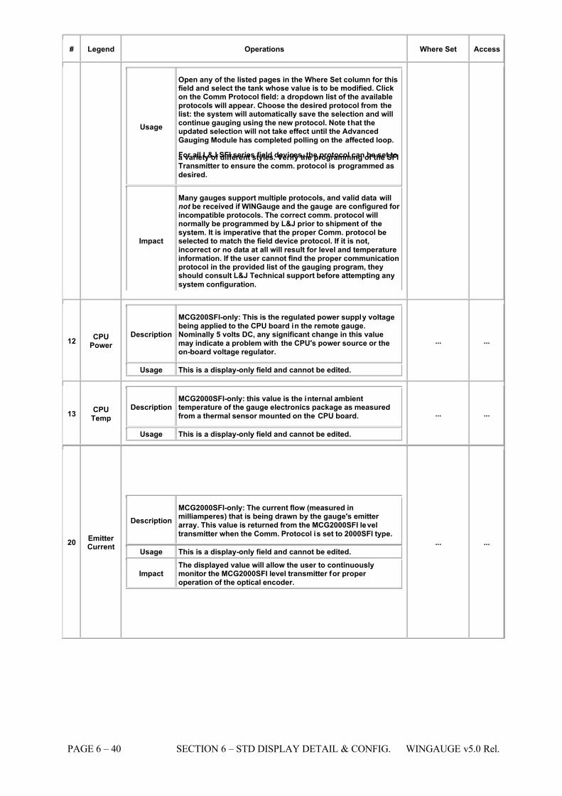
7/16/2019 3900 Manual
http://slidepdf.com/reader/full/3900-manual 88/266
PAGE 6 – 40 SECTION 6 – STD DISPLAY DETAIL & CONFIG. WINGAUGE v5.0 Rel.
# Legend Operations Where Set Access
Usage
Open any of the listed pages in the Where Set column for thisfield and select the tank whose value is to be modified. Clickon the Comm Protocol field: a dropdown list of the availableprotocols will appear. Choose the desired protocol from thelist: the system will automatically save the selection and willcontinue gauging using the new protocol. Note that theupdated selection will not take effect until the AdvancedGauging Module has completed polling on the affected loop.
For all L&J SFI series field devices, the protocol can be set toa variety of different styles. Verify the programming of the SFITransmitter to ensure the comm. protocol is programmed as
desired.
Impact
Many gauges support multiple protocols, and valid data willnot be received if WINGauge and the gauge are configured for incompatible protocols. The correct comm. protocol willnormally be programmed by L&J prior to shipment of thesystem. It is imperative that the proper Comm. protocol beselected to match the field device protocol. If it is not,incorrect or no data at all will result for level and temperatureinformation. If the user cannot find the proper communicationprotocol in the provided list of the gauging program, theyshould consult L&J Technical support before attempting any
system configuration.
12 CPUPower
Description
MCG200SFI-only: This is the regulated power supply voltagebeing applied to the CPU board in the remote gauge.Nominally 5 volts DC, any significant change in this valuemay indicate a problem with the CPU's power source or theon-board voltage regulator.
Usage This is a display-only field and cannot be edited.
... ...
13 CPUTemp
Description MCG2000SFI-only: this value is the internal ambienttemperature of the gauge electronics package as measuredfrom a thermal sensor mounted on the CPU board.
Usage This is a display-only field and cannot be edited.
... ...
20 Emitter Current
Description MCG2000SFI-only: The current flow (measured inmilliamperes) that is being drawn by the gauge's emitter array. This value is returned from the MCG2000SFI leveltransmitter when the Comm. Protocol is set to 2000SFI type.
Usage This is a display-only field and cannot be edited.
Impact The displayed value will allow the user to continuouslymonitor the MCG2000SFI level transmitter for proper operation of the optical encoder.
... ...
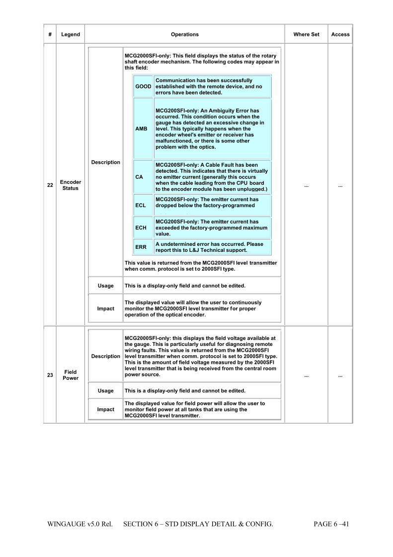
7/16/2019 3900 Manual
http://slidepdf.com/reader/full/3900-manual 89/266
WINGAUGE v5.0 Rel. SECTION 6 – STD DISPLAY DETAIL & CONFIG. PAGE 6 –41
# Legend Operations Where Set Access
22 Encoder Status
Description
MCG2000SFI-only: This field displays the status of the rotaryshaft encoder mechanism. The following codes may appear inthis field:
GOOD Communication has been successfullyestablished with the remote device, and noerrors have been detected.
AMB
MCG200SFI-only: An Ambiguity Error hasoccurred. This condition occurs when thegauge has detected an excessive change inlevel. This typically happens when theencoder wheel's emitter or receiver hasmalfunctioned, or there is some other problem with the optics.
CA
MCG200SFI-only: A Cable Fault has beendetected. This indicates that there is virtuallyno emitter current (generally this occurswhen the cable leading from the CPU boardto the encoder module has been unplugged.)
ECL MCG200SFI-only: The emitter current hasdropped below the factory-programmed
minimum value.
ECH MCG200SFI-only: The emitter current hasexceeded the factory-programmed maximumvalue.
ERR A undetermined error has occurred. Pleasereport this to L&J Technical support.
This value is returned from the MCG2000SFI level transmitter when comm. protocol is set to 2000SFI type.
Usage This is a display-only field and cannot be edited.
Impact The displayed value will allow the user to continuouslymonitor the MCG2000SFI level transmitter for proper operation of the optical encoder.
... ...
23 FieldPower
Description
MCG2000SFI-only: this displays the field voltage available atthe gauge. This is particularly useful for diagnosing remotewiring faults. This value is returned from the MCG2000SFIlevel transmitter when comm. protocol is set to 2000SFI type.This is the amount of field voltage measured by the 2000SFIlevel transmitter that is being received from the central roompower source.
Usage This is a display-only field and cannot be edited.
Impact The displayed value for field power will allow the user tomonitor field power at all tanks that are using theMCG2000SFI level transmitter.
... ...
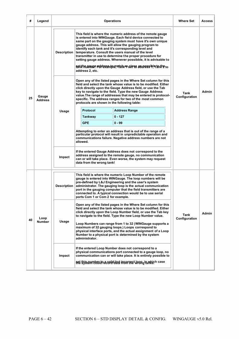
7/16/2019 3900 Manual
http://slidepdf.com/reader/full/3900-manual 90/266
PAGE 6 – 42 SECTION 6 – STD DISPLAY DETAIL & CONFIG. WINGAUGE v5.0 Rel.
# Legend Operations Where Set Access
25 GaugeAddress
Description
This field is where the numeric address of the remote gaugeis entered into WINGauge. Each field device connected tosame part on the gauging system must have it's own uniquegauge address. This will allow the gauging program toidentify each tank and it's corresponding level andtemperature. Consult the users manual of the leveltransmitter in use to determine the proper procedure for setting gauge address. Whenever possibble, it is advisable to
set the gauge address to match as close as possible to thetank number. For example, Tank 1 set to address 1, Tank 2 toaddress 2, etc.
Usage
Open any of the listed pages in the Where Set column for thisfield and select the tank whose value is to be modified. Either click directly upon the Gauge Address field, or use the Tabkey to navigate to the field. Type the new Gauge Addressvalue.The range of addresses that may be entered is protocol-specific. The address ranges for two of the most commonprotocols are shown in the following table:
Protocol Address Range
Tankway 0 - 127
GPE 0 - 99
Attempting to enter an address that is out of the range of aparticular protocol will result in unpredictable operation andcommunications failure. Negative address numbers are notallowed.
Impact If the entered Gauge Address does not correspond to theaddress assigned to the remote gauge, no communicationcan or will take place. Even worse, the system may requestdata from the wrong tank!
TankConfiguration
Admin
40 LoopNumber
Description
This field is where the numeric Loop Number of the remotegauge is entered into WINGauge. The loop numbers will bepre-defined by L&J Engineering and the user's systemadministrator. The gauging loop is the actual communicationport in the gauging computer that the field transmitters areconnected to. A typical connection would be to use serialports Com 1 or Com 2 for example.
Usage
Open any of the listed pages in the Where Set column for thisfield and select the tank whose value is to be modified. Either click directly upon the Loop Number field, or use the Tab keyto navigate to the field. Type the new Loop Number value.
Loop Numbers can range from 1 to 32 (WINGauge supports amaximum of 32 gauging loops.) Loops correspond tophysical interface ports, and the actual assignment of a LoopNumber to a physical port is determined by the systemadministrator.
Impact
If the entered Loop Number does not correspond to aphysical communications port connected to a gauge loop, nocommunication can or will take place. It is entirely possible to
set this number to a valid but incorrect loop, in which casethe system could record data from the wrong tanks.
TankConfiguration
Admin
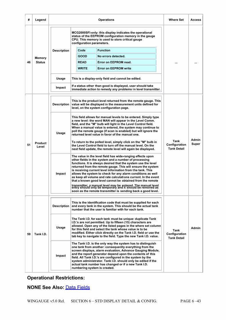
7/16/2019 3900 Manual
http://slidepdf.com/reader/full/3900-manual 91/266
WINGAUGE v5.0 Rel. SECTION 6 – STD DISPLAY DETAIL & CONFIG. PAGE 6 –43
# Legend Operations Where Set Access
46
Memory
Status
Description
MCG2000SFI-only: this display indicates the operationalstatus of the EEPROM configuration memory in the gaugeCPU. This memory is used to store critical gauge
configuration parameters.
Code Function
GOOD No errors detected.
READ Error on EEPROM read. WRITE Error on EEPROM write
Usage This is a display-only field and cannot be edited.
Impact If a status other than good is displayed, user should takeimmediate action to remedy any problems in level transmitter.
... ...
51 ProductLevel
Description This is the product level returned from the remote gauge. Thisvalue will be displayed in the measurement units defined for level, on the system configuration page.
Usage
This field allows for manual levels to be entered. Simply typea new level: the word MAN will appear in the Level Comm.field, and the "M" bulb will light in the Level Control field.When a manual value is entered, the system may continue topoll the remote gauge (if scan is enabled) but will ignore thereturned level value in favor of the manual one.
To return to the polled level, simply click on the "M" bulb inthe Level Control field to turn off the manual level. On thenext field update, the remote level will again be displayed.
Impact
The value in the level field has wide-ranging effects uponother fields in the system and a number of processingfunctions. It is always desired that the system use the levelreturned from the remote gauge. This will ensure the systemis receiving current level information from the tank. Thisallows the system to check for any alarm conditions as wellas keep all volume and rate calculations current. In the eventthat a known good level cannot be obtained from the remote
transmitter, a manual level may be entered. The manual levelentry should only be temporary and it should be removed assoon as the remote transmitter is sending back a good level.
TankConfiguration
Tank Detail
Admin
Super
59 Tank I.D.
Description This is the identification code that must be supplied for eachand every tank in the system. This should be the actual tanknumber that the user is familiar with for each tank.
Usage
The Tank I.D. for each tank must be unique: duplicate TankI.D.'s are not permitted. Up to fifteen (15) characters areallowed. Open any of the listed pages in the where set columnfor this field and select the tank whose value is to bemodified. Either click directly on the Tank I.D. field or use thetab key to navigate to the field. Type the new Tank I.D. value.
Impact
The Tank I.D. is the only way the system has to distinguishone tank from another: consequently everything from thescreen displays, alarm evaluation, Advance Gauging Module,and the report generator depend upon the contents of thisfield. All Tank I.D.'s are configured in the system by thesystem administrator. Tank I.D. should only be edited if theactual tank number has changed or if a new Tank I.D.numbering system is created.
TankConfiguration
Tank Detail
Admin
Operational Restrictions:
NONE See Also: Data Fields
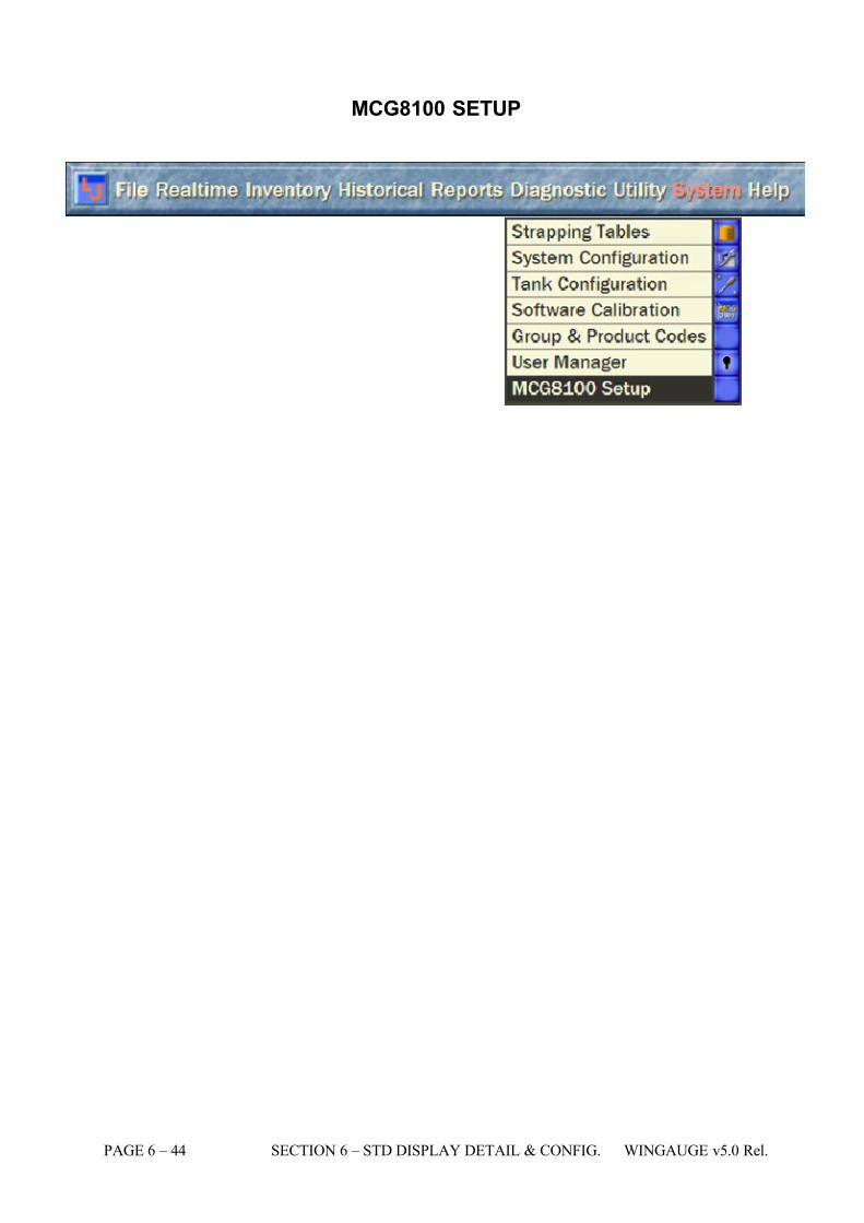
7/16/2019 3900 Manual
http://slidepdf.com/reader/full/3900-manual 92/266
PAGE 6 – 44 SECTION 6 – STD DISPLAY DETAIL & CONFIG. WINGAUGE v5.0 Rel.
MCG8100 SETUP
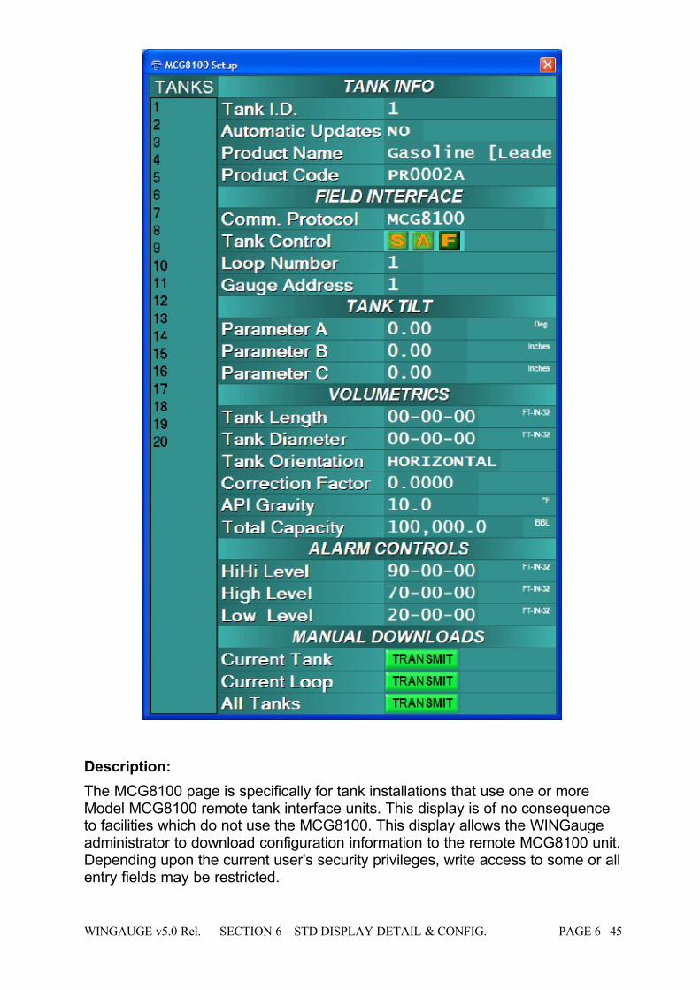
7/16/2019 3900 Manual
http://slidepdf.com/reader/full/3900-manual 93/266
WINGAUGE v5.0 Rel. SECTION 6 – STD DISPLAY DETAIL & CONFIG. PAGE 6 –45
Description:
The MCG8100 page is specifically for tank installations that use one or moreModel MCG8100 remote tank interface units. This display is of no consequenceto facilities which do not use the MCG8100. This display allows the WINGaugeadministrator to download configuration information to the remote MCG8100 unit.Depending upon the current user's security privileges, write access to some or allentry fields may be restricted.
7/16/2019 3900 Manual
http://slidepdf.com/reader/full/3900-manual 94/266
PAGE 6 – 46 SECTION 6 – STD DISPLAY DETAIL & CONFIG. WINGAUGE v5.0 Rel.
When the display is first invoked the TANKS list will have the focus. This listcontains the I.D.'s of all tanks within the system. Simply clicking on any tank inthe list will cause all entry fields to be instantly updated with data from the newlyselected tank. The up and down arrow keys may also be used to navigate theTank list.
The Tab key is used to move between fields. Pressing the Tab key will move thefocus highlight to the next field in the tab order: pressing Shift-Tab (hold down the
Shift and the Tab key simultaneously) will move the highlight to the previous field.
If the user attempts to modify the contents of any entry field without authorization,the User Log-In window will be automatically displayed. The same will happen if there is no active login.
When using the MCG8100, it is important that the Comm. Protocol (i.e.Communications Protocol) be set to MCG8100 for every gauge that is beingmonitored by an 8100. If this setting is incorrect, no data will be received and noconfiguration information can be transmitted.
To have WINGauge automatically transmit any configuration changes as they are
made, set the AUTOMATIC UPDATES field to YES. This is convenient when asingle changes are being made to a large number of different tanks. However, if several fields are to be modified for each tank, it is best to turn this feature off and use the manual download buttons.
The Manual Download section, shown at the bottom of the example page above,has three options, Current Tank, Current Loop and All Tanks. Pressing theCurrent Tank Transmit button will download all fields for the tank currently beingdisplayed on the MCG8100 Setup page. Pressing Current Loop Transmit willdownload configuration information for all tanks that are on the same loop as (i.e.being polled by the same MCG8100 as) the tank currently being displayed. The
All Tanks Transmit button will download data for all
tanks to all MCG8100's beingmonitored by WINGauge.
When a download button is pressed, it will change from green to amber, and willremain in that state until the download process has completed. Only one of thethree buttons may be pressed at any time for any given tank.
Operator Available Functions:
Operational Restrictions:
See Also:
User Log-In
Data Fields
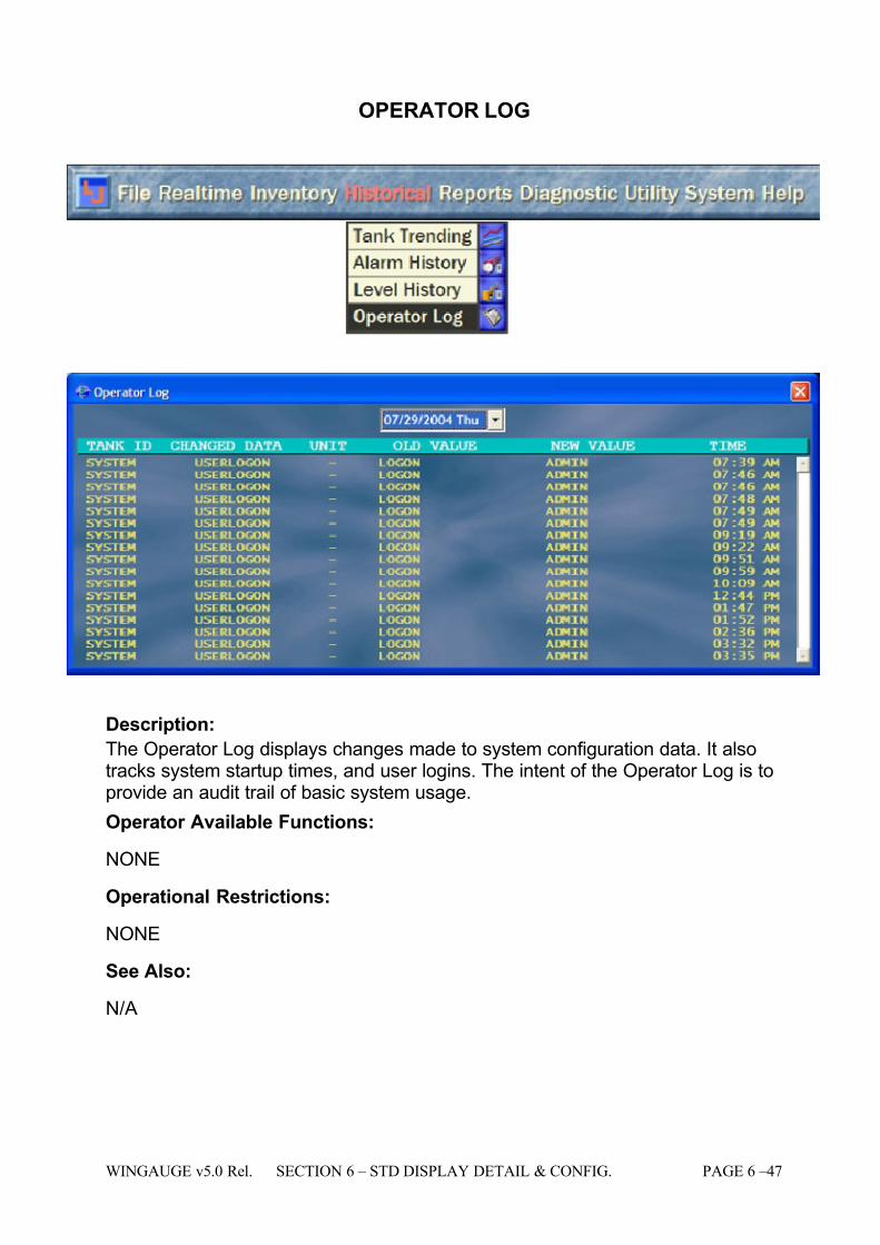
7/16/2019 3900 Manual
http://slidepdf.com/reader/full/3900-manual 95/266
WINGAUGE v5.0 Rel. SECTION 6 – STD DISPLAY DETAIL & CONFIG. PAGE 6 –47
OPERATOR LOG
Description:
The Operator Log displays changes made to system configuration data. It alsotracks system startup times, and user logins. The intent of the Operator Log is toprovide an audit trail of basic system usage.
Operator Available Functions:
NONE
Operational Restrictions:
NONE
See Also:
N/A
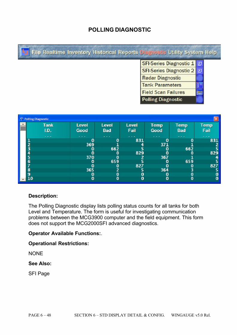
7/16/2019 3900 Manual
http://slidepdf.com/reader/full/3900-manual 96/266
PAGE 6 – 48 SECTION 6 – STD DISPLAY DETAIL & CONFIG. WINGAUGE v5.0 Rel.
POLLING DIAGNOSTIC
Description:
The Polling Diagnostic display lists polling status counts for all tanks for bothLevel and Temperature. The form is useful for investigating communicationproblems between the MCG3900 computer and the field equipment. This formdoes not support the MCG2000SFI advanced diagnostics.
Operator Available Functions:.
Operational Restrictions:
NONE
See Also:
SFI Page
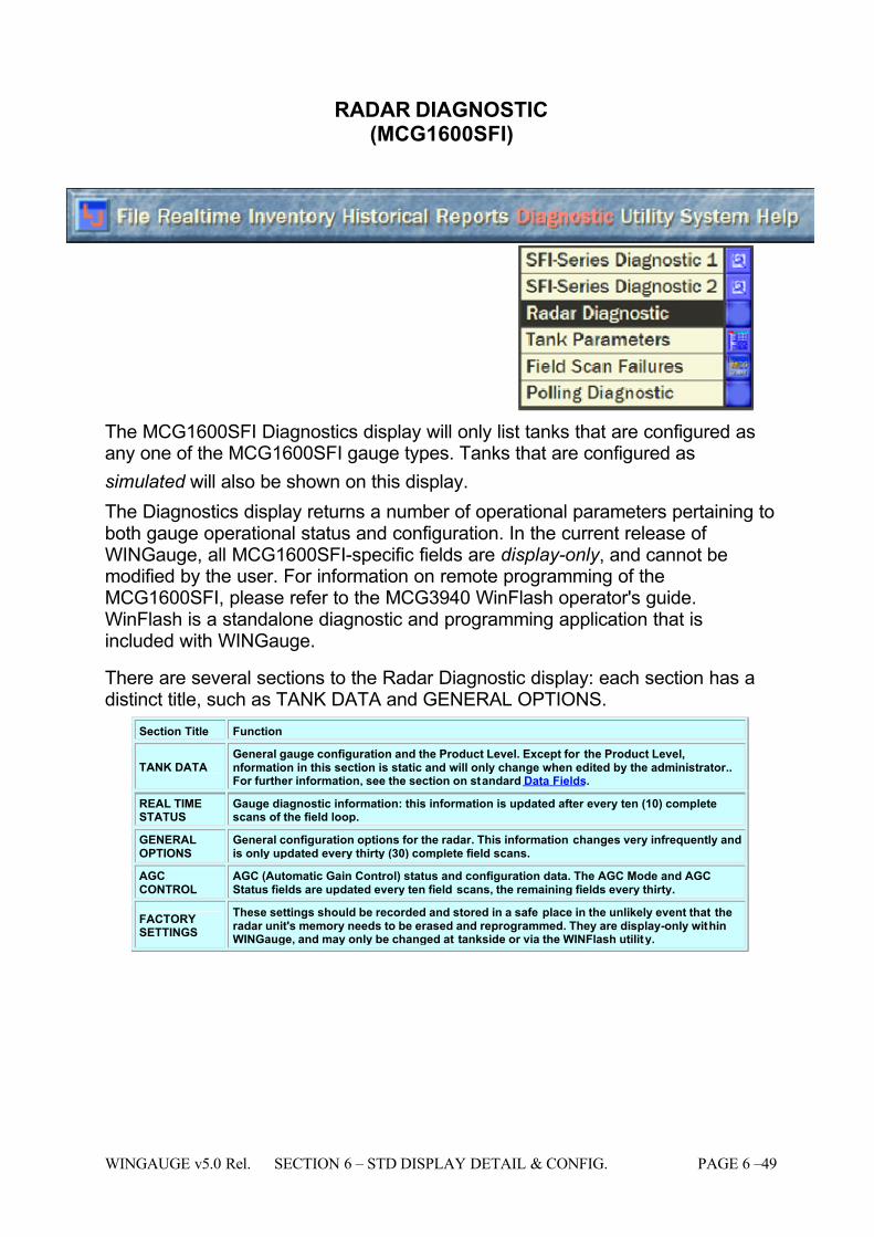
7/16/2019 3900 Manual
http://slidepdf.com/reader/full/3900-manual 97/266
WINGAUGE v5.0 Rel. SECTION 6 – STD DISPLAY DETAIL & CONFIG. PAGE 6 –49
RADAR DIAGNOSTIC(MCG1600SFI)
The MCG1600SFI Diagnostics display will only list tanks that are configured asany one of the MCG1600SFI gauge types. Tanks that are configured as
simulated will also be shown on this display.
The Diagnostics display returns a number of operational parameters pertaining toboth gauge operational status and configuration. In the current release of WINGauge, all MCG1600SFI-specific fields are display-only , and cannot bemodified by the user. For information on remote programming of theMCG1600SFI, please refer to the MCG3940 WinFlash operator's guide.WinFlash is a standalone diagnostic and programming application that isincluded with WINGauge.
There are several sections to the Radar Diagnostic display: each section has adistinct title, such as TANK DATA and GENERAL OPTIONS.
Section Title Function
TANK DATAGeneral gauge configuration and the Product Level. Except for the Product Level,nformation in this section is static and will only change when edited by the administrator..For further information, see the section on standard Data Fields.
REAL TIMESTATUS
Gauge diagnostic information: this information is updated after every ten (10) completescans of the field loop.
GENERALOPTIONS
General configuration options for the radar. This information changes very infrequently andis only updated every thirty (30) complete field scans.
AGCCONTROL
AGC (Automatic Gain Control) status and configuration data. The AGC Mode and AGCStatus fields are updated every ten field scans, the remaining fields every thirty.
FACTORYSETTINGS
These settings should be recorded and stored in a safe place in the unlikely event that theradar unit's memory needs to be erased and reprogrammed. They are display-only withinWINGauge, and may only be changed at tankside or via the WINFlash utility.
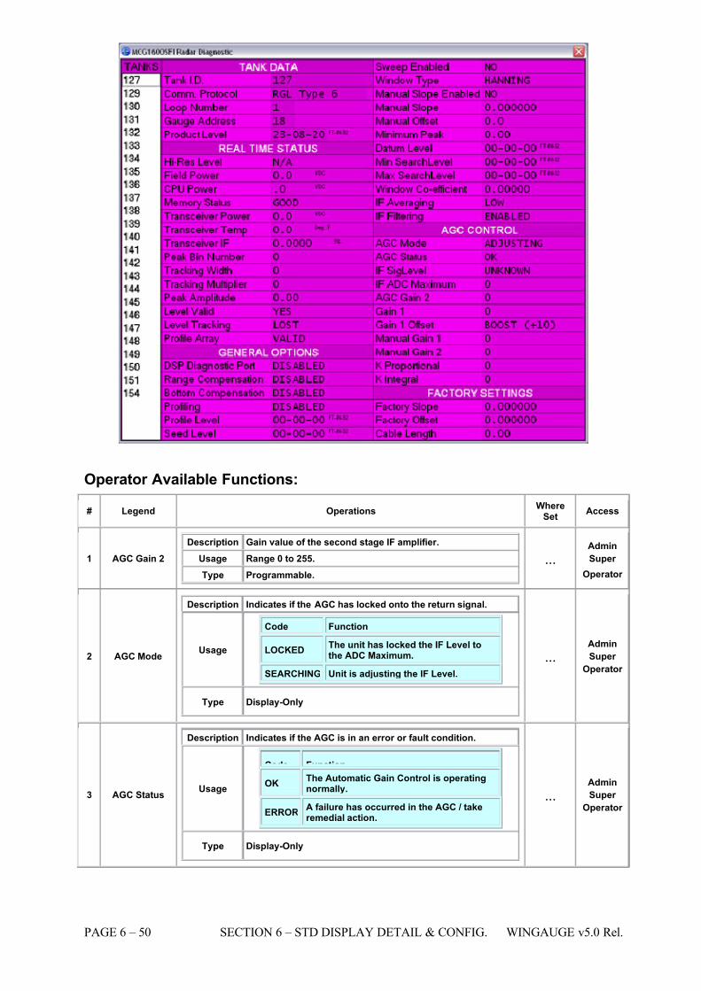
7/16/2019 3900 Manual
http://slidepdf.com/reader/full/3900-manual 98/266
PAGE 6 – 50 SECTION 6 – STD DISPLAY DETAIL & CONFIG. WINGAUGE v5.0 Rel.
Operator Available Functions:
# Legend Operations WhereSet
Access
1 AGC Gain 2 Description Gain value of the second stage IF amplifier.
Usage Range 0 to 255. Type Programmable.
...Admin
Super
Operator
2 AGC Mode
Description Indicates if the AGC has locked onto the return signal.
Usage
Code Function
LOCKED The unit has locked the IF Level tothe ADC Maximum.
SEARCHING Unit is adjusting the IF Level.
Type Display-Only
...Admin
Super
Operator
3 AGC Status
Description Indicates if the AGC is in an error or fault condition.
Usage
Code Function OK The Automatic Gain Control is operating
normally.
ERRORA failure has occurred in the AGC / takeremedial action.
Type Display-Only
...Admin
Super
Operator
7/16/2019 3900 Manual
http://slidepdf.com/reader/full/3900-manual 99/266
WINGAUGE v5.0 Rel. SECTION 6 – STD DISPLAY DETAIL & CONFIG. PAGE 6 –51
# Legend Operations WhereSet
Access
4 BottomCompensation
Description Optional function for tracking at the bottom of a tank.
Usage
Code Function
ENABLEDBottom Compensation has beenenabled (turned on.)
DISABLEDBottom Compensation has beendisabled (turned off.)
Type Programmable
...Admin
Super
Operator
5 CPU Power Description
This is the regulated power supply voltage being applied tothe CPU board in the remote gauge. Any significant changein this value may indicate a problem with the CPU's power source or the on-board voltage regulator.
Usage Nominally 5 volts DC. Type Display-Only.
... ...
6 CPU Temp
Description This value is the internal temperature of the gaugeelectronics package as measured from a thermal sensor mounted on the CPU board.
Usage Shown in Degrees Fahrenheit. Type Display-Only.
... ...
7 Cable Length
Description DSP Board <-> Transceiver Cable Length. Usage Nominally 26.00".
Type Programmable. ...
Admin
Super
Operator
8 DSP Diag PortEnable
Description Indicates if the RS-232 debug port on the DSP board isactive
Usage
Code Function
ENABLED The Debug Port has been enabled(turned on.)
DISABLEDThe Debug Port has been disabled(turned off.)
Type Programmable.
...AdminSuper
Operator
9 Datum Level
Description The physical height of the gauge. Usage Nominally 0 to 95 feet.
Type Programmable. ...
Admin
Super
Operator
10 Factory Offset
Description Factory slope offset (DO NOT MODIFY).
Usage N/A. Type Display-Only.
... AdminSuper
Operator
11 Factory Slope
Description Factory slope setting (DO NOT MODIFY). Usage N/A.
Type Display-Only. ...
Admin
Super
Operator
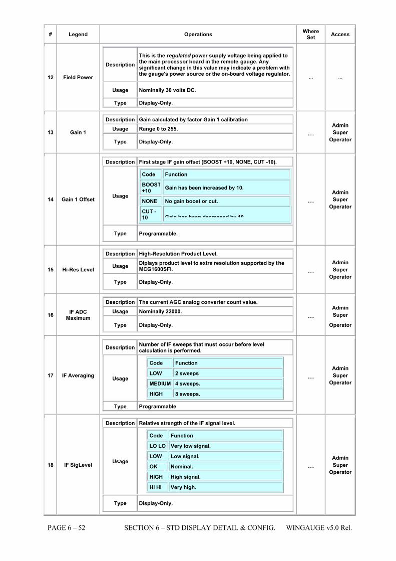
7/16/2019 3900 Manual
http://slidepdf.com/reader/full/3900-manual 100/266
PAGE 6 – 52 SECTION 6 – STD DISPLAY DETAIL & CONFIG. WINGAUGE v5.0 Rel.
# Legend Operations WhereSet
Access
12 Field Power
Description This is the regulated power supply voltage being applied tothe main processor board in the remote gauge. Anysignificant change in this value may indicate a problem withthe gauge's power source or the on-board voltage regulator.
Usage Nominally 30 volts DC.
Type Display-Only.
... ...
13 Gain 1
Description Gain calculated by factor Gain 1 calibration Usage Range 0 to 255.
Type Display-Only. ...
Admin
Super
Operator
14 Gain 1 Offset
Description First stage IF gain offset (BOOST +10, NONE, CUT -10).
Usage
Code Function
BOOST+10
Gain has been increased by 10.
NONE No gain boost or cut.
CUT -10 Gain has been decreased by 10.
Type Programmable.
...Admin
Super
Operator
15 Hi-Res Level
Description High-Resolution Product Level.
Usage Diplays product level to extra resolution supported by theMCG1600SFI.
Type Display-Only.
...Admin
Super
Operator
16 IF ADCMaximum
Description The current AGC analog converter count value. Usage Nominally 22000.
Type Display-Only.
...Admin
Super
Operator
17 IF Averaging
Description Number of IF sweeps that must occur before levelcalculation is performed.
Usage
Code Function
LOW 2 sweeps
MEDIUM 4 sweeps.
HIGH 8 sweeps.
Type Programmable
...Admin
Super
Operator
18 IF SigLevel
Description Relative strength of the IF signal level.
Usage
Code Function
LO LO Very low signal.
LOW Low signal.
OK Nominal.
HIGH High signal.
HI HI Very high.
Type Display-Only.
...Admin
Super
Operator
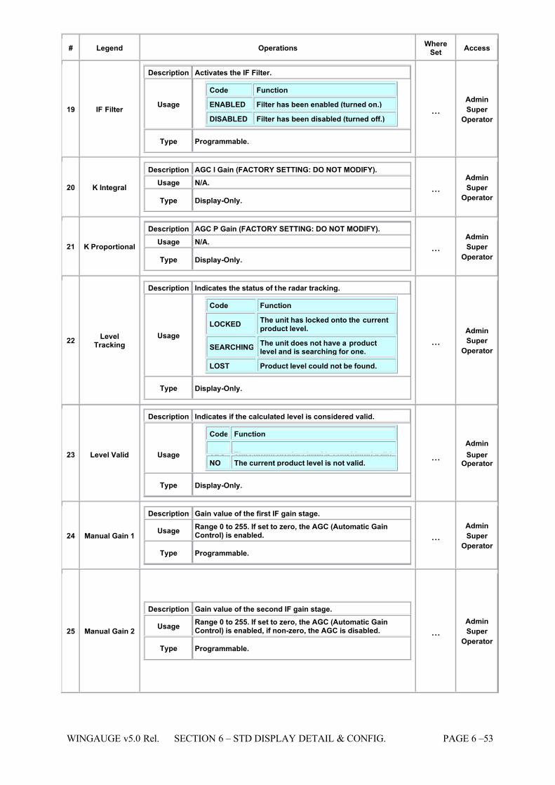
7/16/2019 3900 Manual
http://slidepdf.com/reader/full/3900-manual 101/266
WINGAUGE v5.0 Rel. SECTION 6 – STD DISPLAY DETAIL & CONFIG. PAGE 6 –53
# Legend Operations WhereSet
Access
19 IF Filter
Description Activates the IF Filter.
Usage
Code Function
ENABLED Filter has been enabled (turned on.)
DISABLED Filter has been disabled (turned off.)
Type Programmable.
...Admin
Super
Operator
20 K Integral
Description AGC I Gain (FACTORY SETTING: DO NOT MODIFY). Usage N/A.
Type Display-Only. ...
Admin
Super
Operator
21 K Proportional
Description AGC P Gain (FACTORY SETTING: DO NOT MODIFY). Usage N/A.
Type Display-Only. ...
Admin
Super
Operator
22 LevelTracking
Description Indicates the status of the radar tracking.
Usage
Code Function
LOCKED The unit has locked onto the currentproduct level.
SEARCHINGThe unit does not have a productlevel and is searching for one.
LOST Product level could not be found.
Type Display-Only.
...Admin
Super
Operator
23 Level Valid
Description Indicates if the calculated level is considered valid.
Usage
Code Function
YES The current product level is considered valid.NO The current product level is not valid.
Type Display-Only.
...
Admin
Super Operator
24 Manual Gain 1
Description Gain value of the first IF gain stage.
Usage Range 0 to 255. If set to zero, the AGC (Automatic GainControl) is enabled.
Type Programmable.
...Admin
Super
Operator
25 Manual Gain 2
Description Gain value of the second IF gain stage.
Usage Range 0 to 255. If set to zero, the AGC (Automatic GainControl) is enabled, if non-zero, the AGC is disabled.
Type Programmable.
...Admin
Super
Operator
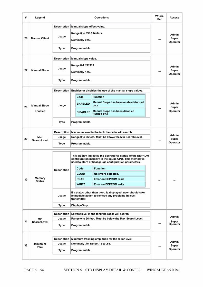
7/16/2019 3900 Manual
http://slidepdf.com/reader/full/3900-manual 102/266
PAGE 6 – 54 SECTION 6 – STD DISPLAY DETAIL & CONFIG. WINGAUGE v5.0 Rel.
# Legend Operations WhereSet
Access
26 Manual Offset
Description Manual slope offset value.
Usage Range 0 to 999.9 Meters.
Nominally 0.00.
Type Programmable.
...Admin
Super
Operator
27 Manual Slope
Description Manual slope value.
Usage Range 0-1.999999.
Nominally 1.00.
Type Programmable.
...Admin
Super
Operator
28 Manual Slope
Enabled
Description Enables or disables the use of the manual slope values.
Usage
Code Function
ENABLEDManual Slope has been enabled (turnedon.)
DISABLED Manual Slope has been disabled(turned off.)
Type Programmable.
...Admin
Super
Operator
29 MaxSearchLevel
Description Maximum level in the tank the radar will search. Usage Range 0 to 96 feet. Must be above the Min SearchLevel.
Type Programmable. ...
Admin
Super
Operator
30 MemoryStatus
Description
This display indicates the operational status of the EEPROMconfiguration memory in the gauge CPU. This memory isused to store critical gauge configuration parameters.
Code Function
GOOD No errors detected.
READ Error on EEPROM read.
WRITE Error on EEPROM write
Usage If a status other than good is displayed, user should takeimmediate action to remedy any problems in leveltransmitter.
Type Display-Only.
... ...
31 Min
SearchLevel
Description Lowest level in the tank the radar will search. Usage Range 0 to 96 feet. Must be below the Max SearchLevel.
Type Programmable. ...
Admin
Super Operator
32 MinimumPeak
Description Minimum tracking amplitude for the radar level. Usage Nominally .45, range .15 to .65.
Type Programmable. ...
Admin
Super
Operator
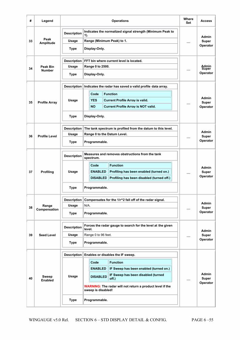
7/16/2019 3900 Manual
http://slidepdf.com/reader/full/3900-manual 103/266
WINGAUGE v5.0 Rel. SECTION 6 – STD DISPLAY DETAIL & CONFIG. PAGE 6 –55
# Legend Operations WhereSet
Access
33 PeakAmplitude
Description Indicates the normalized signal strength (Minimum Peak to1).
Usage Range (Minimum Peak) to 1.
Type Display-Only.
...Admin
Super
Operator
34 Peak BinNumber
Description FFT bin where current level is located. Usage Range 0 to 2500.
Type Display-Only. ...
AdminSuper
Operator
35 Profile Array
Description Indicates the radar has saved a valid profile data array.
Usage
Code Function
YES Current Profile Array is valid.
NO Current Profile Array is NOT valid.
Type Display-Only.
...Admin
Super
Operator
36 Profile Level
Description
The tank spectrum is profiled from the datum to this level.
Usage Range 0 to the Datum Level.
Type Programmable. ...
Admin
Super
Operator
37 Profiling
Description Measures and removes obstructions from the tankspectrum.
Usage
Code Function
ENABLED Profiling has been enabled (turned on.)
DISABLED Profiling has been disabled (turned off.)
Type Programmable.
...Admin
Super
Operator
38 RangeCompensation
Description Compensates for the 1/r^2 fall off of the radar signal. Usage N/A.
Type Programmable. ...
Admin
Super
Operator
39 Seed Level
Description Forces the radar gauge to search for the level at the givenlevel.
Usage Range 0 to 96 feet.
Type Programmable.
...Admin
Super
Operator
40 SweepEnabled
Description Enables or disables the IF sweep.
Usage
Code Function ENABLED IF Sweep has been enabled (turned on.)
DISABLEDIF Sweep has been disabled (turnedoff.)
WARNING: The radar will not return a product level if thesweep is disabled!
Type Programmable.
...Admin
Super
Operator
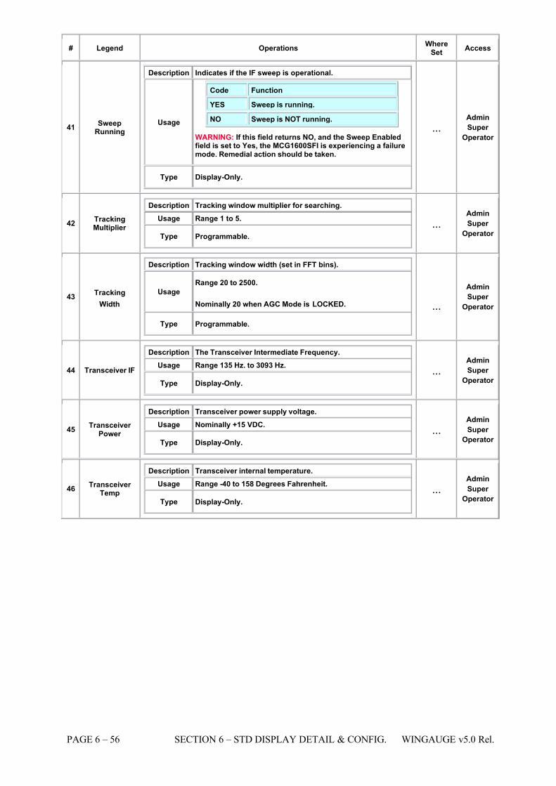
7/16/2019 3900 Manual
http://slidepdf.com/reader/full/3900-manual 104/266
PAGE 6 – 56 SECTION 6 – STD DISPLAY DETAIL & CONFIG. WINGAUGE v5.0 Rel.
# Legend Operations WhereSet
Access
41 SweepRunning
Description Indicates if the IF sweep is operational.
Usage
Code Function
YES Sweep is running.
NO Sweep is NOT running.
WARNING: If this field returns NO, and the Sweep Enabledfield is set to Yes, the MCG1600SFI is experiencing a failuremode. Remedial action should be taken.
Type Display-Only.
...Admin
Super
Operator
42 TrackingMultiplier
Description Tracking window multiplier for searching. Usage Range 1 to 5.
Type Programmable. ...
Admin
Super
Operator
43
Tracking
Width
Description Tracking window width (set in FFT bins).
Usage Range 20 to 2500.
Nominally 20 when AGC Mode is LOCKED.
Type Programmable.
...
Admin
Super
Operator
44 Transceiver IF
Description The Transceiver Intermediate Frequency. Usage Range 135 Hz. to 3093 Hz.
Type Display-Only. ...
Admin
Super
Operator
45 Transceiver Power
Description Transceiver power supply voltage. Usage Nominally +15 VDC.
Type Display-Only. ...
Admin
Super
Operator
46 Transceiver Temp
Description Transceiver internal temperature. Usage Range -40 to 158 Degrees Fahrenheit.
Type Display-Only. ...
Admin
Super
Operator
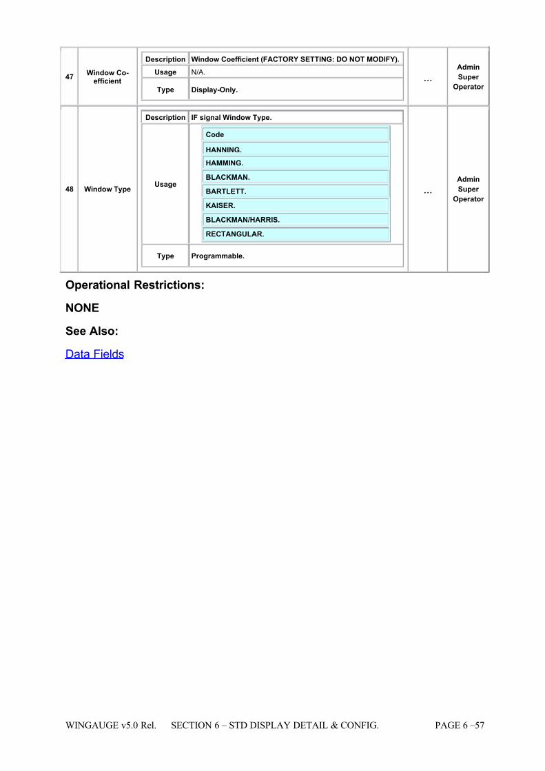
7/16/2019 3900 Manual
http://slidepdf.com/reader/full/3900-manual 105/266
WINGAUGE v5.0 Rel. SECTION 6 – STD DISPLAY DETAIL & CONFIG. PAGE 6 –57
47 Window Co-efficient
Description Window Coefficient (FACTORY SETTING: DO NOT MODIFY). Usage N/A.
Type Display-Only. ...
Admin
Super
Operator
48 Window Type
Description IF signal Window Type.
Usage
Code
HANNING. HAMMING.
BLACKMAN.
BARTLETT.
KAISER.
BLACKMAN/HARRIS.
RECTANGULAR.
Type Programmable.
...Admin
Super
Operator
Operational Restrictions:
NONE
See Also:
Data Fields
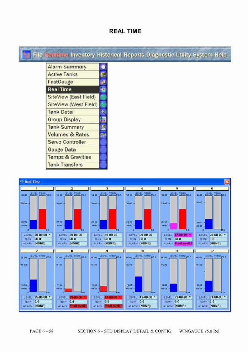
7/16/2019 3900 Manual
http://slidepdf.com/reader/full/3900-manual 106/266
PAGE 6 – 58 SECTION 6 – STD DISPLAY DETAIL & CONFIG. WINGAUGE v5.0 Rel.
REAL TIME
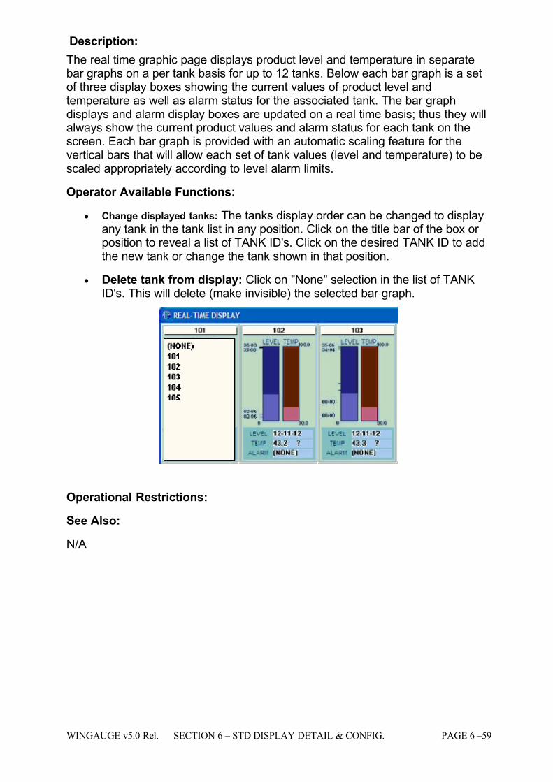
7/16/2019 3900 Manual
http://slidepdf.com/reader/full/3900-manual 107/266
WINGAUGE v5.0 Rel. SECTION 6 – STD DISPLAY DETAIL & CONFIG. PAGE 6 –59
Description:
The real time graphic page displays product level and temperature in separatebar graphs on a per tank basis for up to 12 tanks. Below each bar graph is a setof three display boxes showing the current values of product level andtemperature as well as alarm status for the associated tank. The bar graphdisplays and alarm display boxes are updated on a real time basis; thus they willalways show the current product values and alarm status for each tank on thescreen. Each bar graph is provided with an automatic scaling feature for thevertical bars that will allow each set of tank values (level and temperature) to bescaled appropriately according to level alarm limits.
Operator Available Functions:
• Change displayed tanks: The tanks display order can be changed to displayany tank in the tank list in any position. Click on the title bar of the box or position to reveal a list of TANK ID's. Click on the desired TANK ID to addthe new tank or change the tank shown in that position.
• Delete tank from display: Click on "None" selection in the list of TANKID's. This will delete (make invisible) the selected bar graph.
Operational Restrictions:
See Also:
N/A
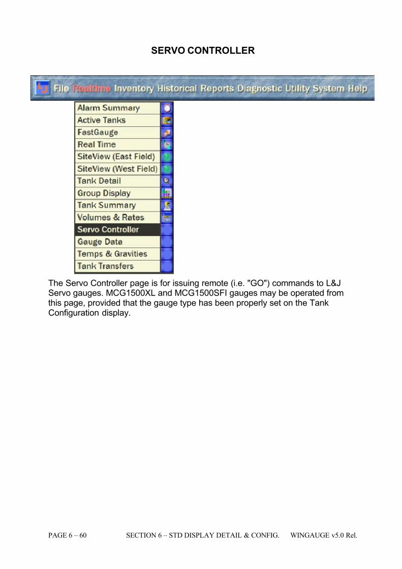
7/16/2019 3900 Manual
http://slidepdf.com/reader/full/3900-manual 108/266
PAGE 6 – 60 SECTION 6 – STD DISPLAY DETAIL & CONFIG. WINGAUGE v5.0 Rel.
SERVO CONTROLLER
The Servo Controller page is for issuing remote (i.e. "GO") commands to L&JServo gauges. MCG1500XL and MCG1500SFI gauges may be operated fromthis page, provided that the gauge type has been properly set on the TankConfiguration display.
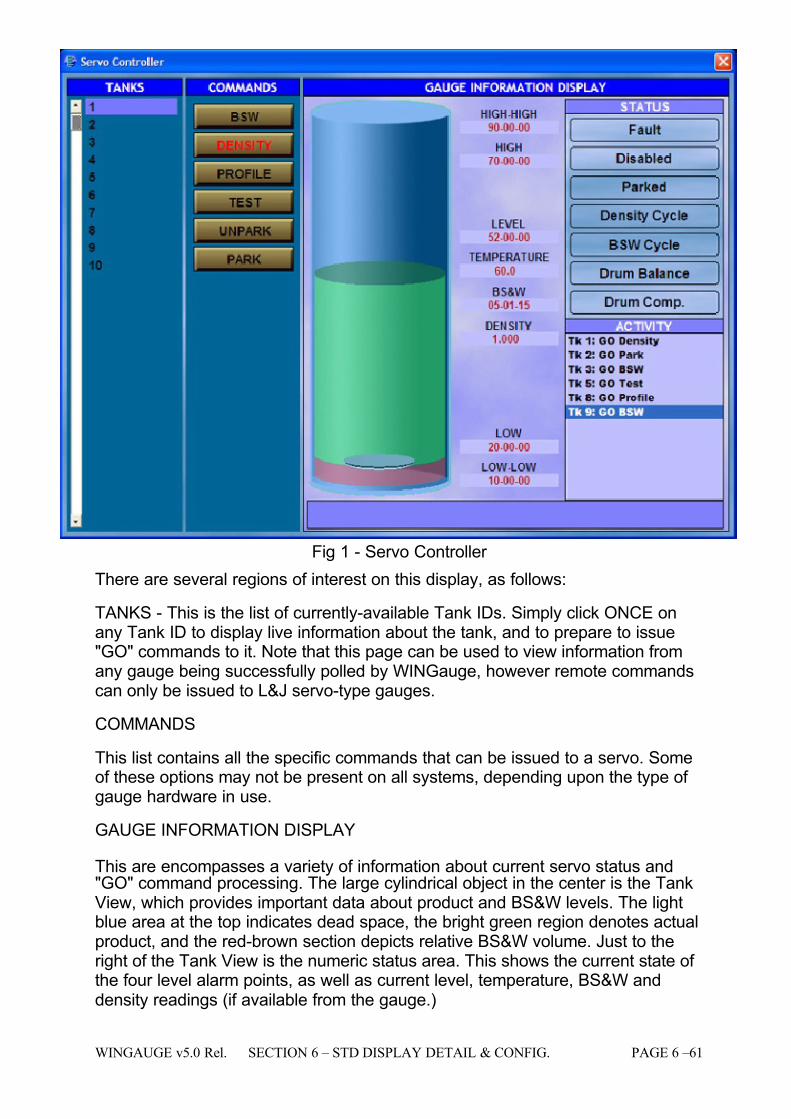
7/16/2019 3900 Manual
http://slidepdf.com/reader/full/3900-manual 109/266
WINGAUGE v5.0 Rel. SECTION 6 – STD DISPLAY DETAIL & CONFIG. PAGE 6 –61
Fig 1 - Servo Controller
There are several regions of interest on this display, as follows:
TANKS - This is the list of currently-available Tank IDs. Simply click ONCE onany Tank ID to display live information about the tank, and to prepare to issue"GO" commands to it. Note that this page can be used to view information fromany gauge being successfully polled by WINGauge, however remote commandscan only be issued to L&J servo-type gauges.
COMMANDS
This list contains all the specific commands that can be issued to a servo. Someof these options may not be present on all systems, depending upon the type of gauge hardware in use.
GAUGE INFORMATION DISPLAY
This are encompasses a variety of information about current servo status and"GO" command processing. The large cylindrical object in the center is the TankView, which provides important data about product and BS&W levels. The lightblue area at the top indicates dead space, the bright green region denotes actualproduct, and the red-brown section depicts relative BS&W volume. Just to theright of the Tank View is the numeric status area. This shows the current state of the four level alarm points, as well as current level, temperature, BS&W anddensity readings (if available from the gauge.)
7/16/2019 3900 Manual
http://slidepdf.com/reader/full/3900-manual 110/266
PAGE 6 – 62 SECTION 6 – STD DISPLAY DETAIL & CONFIG. WINGAUGE v5.0 Rel.
STATUS
The Status frame is simply a readout of several status bits that are polled fromthe remote servo gauge. Each of the seven states is OFF in the example, but if any of them were active the corresponding indicator would light. Please refer tothe User's Manual for the gauge for more information on the meaning andinterpretation of these indicators.
ACTIVITY
This is simply a log of the most recent servo "GO" commands issued to allgauges. Notice that the leftmost characters in each line of the log are the TankID, followed by the actual command that was issued to the tank. If any errors or faults occur, they will be shown in the log as well. The log is not preserved acrossa system restart.
Operator Available Functions:
ALL
# Legend Operations Where Set Access
4 AvailableStorage
Description
The volume of unused space available in the tank. This valueis calculated by taking the Total Tank Capacity entered bythe end user and subtracting the Gross Volume derived fromthe strapping table for the current tank level. The value isnot editable but will change as product level moves or if Total Capacity Value changes.
Usage This is a display-only field and cannot be edited. Definition (Total Volume - Gross Volume)
... ...
8 BS&WLevel
Description The level of water and sediment at the bottom of the tank(i.e., Bottom Sediment & Water.)
Usage
Open any of the listed pages in the Where Set column for this field and select the tank whose value is to be modified.Either click directly upon the BS&W Level field, or use theTab key to navigate to the field. Type the new BS&W Levelvalue. The value is entered in the system units chosen for Level.
This value is normally user-defined, but can be a live valuewhen using servo gauges or other devices capable of detecting the BS&W level. If a field device is used tomeasure the BS&W level, it will need to be configured on theTank Configuration page for the proper Comm. Protocol. Themost common type of L&J BS&W level measuring device isthe MCG 1500 Series Gauge which is Type 8. When this typeis selected, it will instruct the gauging program to retrievethe measured BS&W level from the MCG 1500XL SeriesGauge whenever it polls the servo for product level andtemperature.
Impact The BS&W Level value is used to determine the BS&WVolume.
TankConfiguration
Tank Detail
Admin
Super
7/16/2019 3900 Manual
http://slidepdf.com/reader/full/3900-manual 111/266
WINGAUGE v5.0 Rel. SECTION 6 – STD DISPLAY DETAIL & CONFIG. PAGE 6 –63
# Legend Operations Where Set Access
19 Density
Description Product density, displayed in the system units specified for Density.. For transmitters that do not return this data, amanual entry must be provided. Alarm evaluation is notavailable for Density.
Usage Open any of the listed pages in the Where Set column for this field and select the tank whose value is to be modified.Either click directly upon the Density field, or use the Tabkey to navigate to the field. Type the new Density value.
Impact
The entered Density affects the calculated API correctionfactor, which in turn affects the derived Net Volume value.
NOTE: If you do not have a valid remote temperature value,and/or have not entered a manual temperature, the systemwill automatically set the internal correction factor to 1regardless of the API Table setting or the displayed APIvalue. This effectively references the system to 60 degreesFahrenheit, which is standard for most API calculations.
See the Temp Control and the Product Temp fielddescriptions below for more information on setting a manualtemperature, and the behavior of the product temperaturedisplay field under fault conditions.
... Admin
Super
29 HighLevel
Description
Alarm Setpoint: when the current level equals or exceedsthis value, a High Level alarm will occur. The alarm conditionwill be logged to both the Alarm Summary and Alarm Historydisplays, and appropriate alarm colors will be generated ondisplays that support them. Multimedia equipped systemswill generate a warning class alarm sound from thespeakers.
Usage
Open any of the listed pages in the Where Set column for this field and select the tank whose value is to be modified.Either click directly upon the High Level field, or use the Tabkey to navigate to the field. Type the new High Level value.The value is entered in the system units chosen for Level.
This value is always user-defined.
Impact
The system level alarm detection and evaluation routinesdepend entirely upon the proper setting of the various alarmlevels. Failure to set the alarm levels correctly may causethe system to generate spurious alarms or fail to detect
dangerous conditions.
Tank Detail
Admin
Super
32 HiHi Level
Description
Alarm Setpoint: when the current level equals or exceedsthis value, a HiHi Level alarm will occur. The alarm conditionwill be logged to both the Alarm Summary and Alarm Historydisplays, and appropriate alarm colors will be generated ondisplays that support them. Multimedia equipped systemswill generate an emergency class alarm sound from thespeakers.
Usage
Open any of the listed pages in the Where Set column for this field and select the tank whose value is to be modified.Either click directly upon the HiHi Level field, or use the Tab
key to navigate to the field. Type the new HiHi Level value.The value is entered in the system units chosen for Level.
This value is always user-defined.
Impact
The system level alarm detection and evaluation routinesdepend entirely upon the proper setting of the various alarmlevels. Failure to set the alarm levels correctly may causethe system to generate spurious alarms or fail to detectdangerous conditions.
Tank Detail Admin
Super
7/16/2019 3900 Manual
http://slidepdf.com/reader/full/3900-manual 112/266
PAGE 6 – 64 SECTION 6 – STD DISPLAY DETAIL & CONFIG. WINGAUGE v5.0 Rel.
# Legend Operations Where Set Access
39 LoLoLevel
Description
Alarm Setpoint: when the current level is equal to or lessthan this value, a LoLo Level alarm will occur. The alarmcondition will be logged to both the Alarm Summary andAlarm History displays, and appropriate alarm colors will begenerated on displays that support them. Multimediaequipped systems will generate an emergency class alarmsound from the speakers.
Usage
Open any of the listed pages in the Where Set column for
this field and select the tank whose value is to be modified.Either click directly upon the LoLo Level field, or use the Tabkey to navigate to the field. Type the new LoLo Level value.The value is entered in the system units chosen for Level.
This value is always user-defined.
Impact
The system level alarm detection and evaluation routinesdepend entirely upon the proper setting of the various alarmlevels. Failure to set the alarm levels correctly may causethe system to generate spurious alarms or fail to detectdangerous conditions.
Tank Detail Admin
42 Low Level
Description
Alarm Setpoint: when the current level is equal to or lessthan this value, a Low Level alarm will occur. The alarm
condition will be logged to both the Alarm Summary andAlarm History displays, and appropriate alarm colors will begenerated on displays that support them. Multimediaequipped systems will generate a warning class alarmsound from the speakers.
Usage
Open any of the listed pages in the Where Set column for this field and select the tank whose value is to be modified.Either click directly upon the Low Level field, or use the Tabkey to navigate to the field. Type the new Low Level value.The value is entered in the system units chosen for Level.
This value is always user-defined.
Impact
The system level alarm detection and evaluation routinesdepend entirely upon the proper setting of the various alarmlevels. Failure to set the alarm levels correctly may cause
the system to generate spurious alarms or fail to detectdangerous conditions.
Tank Detail
Admin
51 ProductLevel
Description This is the product level returned from the remote gauge.This value will be displayed in the measurement unitsdefined for level, on the system configuration page.
Usage
This field allows for manual levels to be entered. Simply typea new level: the word MAN will appear in the Level Comm.field, and the "M" bulb will light in the Level Control field.When a manual value is entered, the system may continue topoll the remote gauge (if scan is enabled) but will ignore thereturned level value in favor of the manual one.
To return to the polled level, simply click on the "M" bulb in
the Level Control field to turn off the manual level. On thenext field update, the remote level will again be displayed.
TankConfiguration
Tank Detail
Admin
Super
7/16/2019 3900 Manual
http://slidepdf.com/reader/full/3900-manual 113/266
WINGAUGE v5.0 Rel. SECTION 6 – STD DISPLAY DETAIL & CONFIG. PAGE 6 –65
# Legend Operations Where Set Access
Impact
The value in the level field has wide-ranging effects uponother fields in the system and a number of processingfunctions. It is always desired that the system use the levelreturned from the remote gauge. This will ensure the systemis receiving current level information from the tank. Thisallows the system to check for any alarm conditions as wellas keep all volume and rate calculations current. In the eventthat a known good level cannot be obtained from the remotetransmitter, a manual level may be entered. The manual level
entry should only be temporary and it should be removed assoon as the remote transmitter is sending back a good level.
54 ProductTemp
Description This is the product temperature returned from the remotegauge. This value will be displayed in the measurementunits defined for temperature, on the system configurationpage.
Usage
This field allows for manual temperatures to be entered.Simply type a new temperature: the word MAN will appear inthe Temp Comm. field, and the "M" bulb will light in theTemp Control field. When a manual value is entered, the
system may continue to poll the remote gauge (if scan isenabled) but will ignore the returned temperature value infavor of the manual one.
To return to the polled temperature, simply click on the "M"bulb in the Temp Control field to turn off the manualtemperature. On the next field update, the remotetemperature will again be displayed.
Impact A valid product temperature is essential for the system toaccurately calculate net volume values. A field value or manually entered value should always be present to ensureproper volume calculations.
TankConfiguration
Tank Detail
Admin
Super
59 Tank I.D.
Description This is the identification code that must be supplied for eachand every tank in the system. This should be the actual tank
number that the user is familiar with for each tank.
Usage
The Tank I.D. for each tank must be unique: duplicate TankI.D.'s are not permitted. Up to fifteen (15) characters areallowed. Open any of the listed pages in the where setcolumn for this field and select the tank whose value is to bemodified. Either click directly on the Tank I.D. field or usethe tab key to navigate to the field. Type the new Tank I.D.value.
Impact
The Tank I.D. is the only way the system has to distinguishone tank from another: consequently everything from thescreen displays, alarm evaluation, Advance GaugingModule, and the report generator depend upon the contentsof this field. All Tank I.D.'s are configured in the system bythe system administrator. Tank I.D. should only be edited if the actual tank number has changed or if a new Tank I.D.
numbering system is created.
TankConfiguration
Tank Detail
Admin
Operational Restrictions:
NONE
See Also: Data Fields
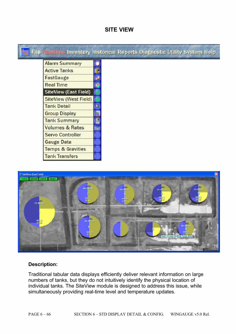
7/16/2019 3900 Manual
http://slidepdf.com/reader/full/3900-manual 114/266
PAGE 6 – 66 SECTION 6 – STD DISPLAY DETAIL & CONFIG. WINGAUGE v5.0 Rel.
SITE VIEW
Description:
Traditional tabular data displays efficiently deliver relevant information on largenumbers of tanks, but they do not intuitively identify the physical location of individual tanks. The SiteView module is designed to address this issue, whilesimultaneously providing real-time level and temperature updates.
7/16/2019 3900 Manual
http://slidepdf.com/reader/full/3900-manual 115/266
WINGAUGE v5.0 Rel. SECTION 6 – STD DISPLAY DETAIL & CONFIG. PAGE 6 –67
SiteView sports a sophisticated zooming interface to customer-supplied mapimagery, and will superimpose computer generated graphics upon the mapsurface. Actual installation of map images and corresponding menu and toolbar configuration is an admistrator function that is beyond the scope of this manual.
Views may be created of different parts of a single facility, or even of entirelydifferent facilities, and may be displayed simultaneously on-screen. In theexample menu above, notice that there are "East" and "West" SiteView options,
which would depict two different regions. This is very useful when using theMultifield Integrated Gauging capabilities of the MCG3900, as data from morethan one gauging server may be combined and viewed on any client or server onthe network.
Operator Available Functions:
When SiteView is activated, it will attempt to display the entire map graphic withinthe confines of the available screen resolution. This makes for an excellentoverview of an entire site. Notice the circular objects that overlay each tank at thesample facility shown. Superimposed upon these "tank objects" are several textitems. At the very center is the Tank ID: the samples tanks range from Tank 1 toTank 9. Above that is the live product level value, displayed in the standardsystem units chosen for level. Below the Tank ID is the current producttemperature, also in system units. Notice that several of the tanks are display999 for temperature. This indicates that the gauge either does not supporttemperature acquisition, or that there is a communications fault. Level values willgo to above 96 feet if there is a problem with level communication. Please seethe Field Scan Failures display for further information if a problem is suspected.
In addition to the numeric readouts, the tank objects actually comprise compactbar graphs that visually display the level (on the left side of each object) andtemperature (on the right side.) The ranges are scaled to between the high-high
and low-low alarm levels specified for each tank. For example, look closely atTank 1 (the largest object, the one at the left). Notice that the level (the brightblue portion) is near the bottom of the circle, indicating that this tank is nearlyempty. On the right hand side, the bright yellow portion indicates that thetemperature is near the middle of the temperature alarm range.
Should any tanks go into an alarm state, the corresponding half of the associatedtank object will change colors to match the alarm colors used throughout the restof the program. This also includes tank motion indication (up is blue, down isgreen.) For example, if the level for Tank 2 were to exceed specified limits, theleft half of Tank 2's tank object would change color. Likewise, if the temperature
were to exceed the programmed limits, the right half of the tank object wouldchange color. This allows the operator to have an immediate overview of theentire tank farm's operational status, including the physical location of the tanks.
The window may be resized as desired, and the map image and all of the mapobjects will resize to fit. Should more detail be desired, clicking on the greenZOOM button will activate zoom mode. Left-clicking on the map, and holdingdown the button will zoom IN, right-clicking and holding will zoom the map OUT.
7/16/2019 3900 Manual
http://slidepdf.com/reader/full/3900-manual 116/266
PAGE 6 – 68 SECTION 6 – STD DISPLAY DETAIL & CONFIG. WINGAUGE v5.0 Rel.
The entire map may be displayed again by clicking on the RESET button: thisdisables zoom and returns to the default settings.
If any particular tank object is too small to display the level and temperature fields(because the window has been reduced in size, or because a very large,complicated SiteView is being rendered) the system will only display the Tank IDin the center (see tanks 4 and 7 in the example.) However, by holding the mouseover any object which is not displaying numeric data, a floating tooltip will appear,
containing the live level and temperature values.
Once an alarm has been acknowledged (via the Alarm Summary screen), theassociated tank object will change to the acknowledged alarm color set. Thisindicates that, while the operator has indicated his awareness of the alarm, thecondition is still in effect. The actual color will depend upon the type of alarm(high level, hi-hi level, low level, etc.) When the system can no longer detect thealarm condition and it has been acknowledged by the operator, the backgroundcolor will return to the nominal blue and yellow, for level and temperature,respectively.
The actual alarm acknowledged alarm colors in use at a particular site may vary
depending how the system administrator has configured the system.
Operational Restrictions:
NONE
See Also:
Tank Detail
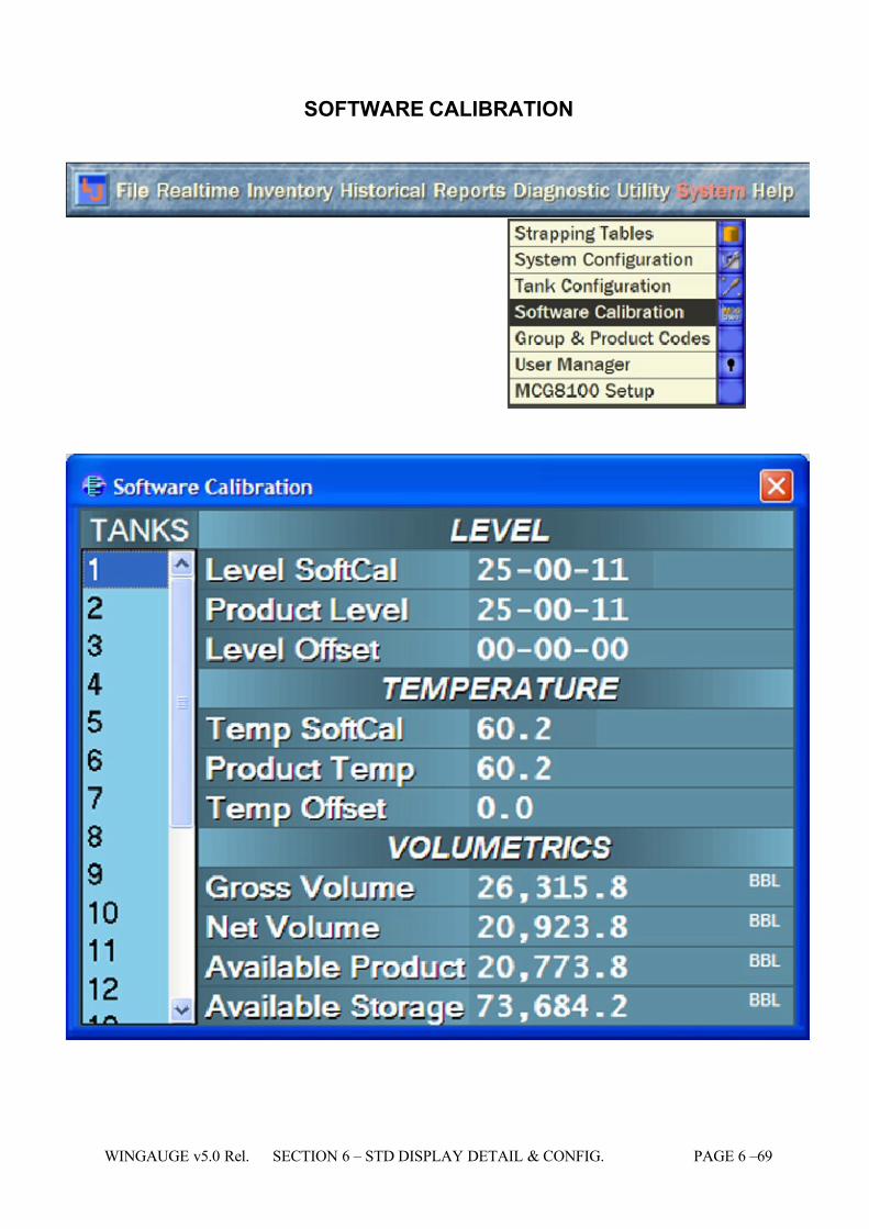
7/16/2019 3900 Manual
http://slidepdf.com/reader/full/3900-manual 117/266
WINGAUGE v5.0 Rel. SECTION 6 – STD DISPLAY DETAIL & CONFIG. PAGE 6 –69
SOFTWARE CALIBRATION
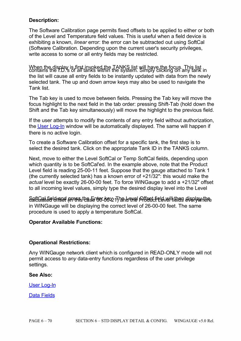
7/16/2019 3900 Manual
http://slidepdf.com/reader/full/3900-manual 118/266
PAGE 6 – 70 SECTION 6 – STD DISPLAY DETAIL & CONFIG. WINGAUGE v5.0 Rel.
Description:
The Software Calibration page permits fixed offsets to be applied to either or bothof the Level and Temperature field values. This is useful when a field device isexhibiting a known, linear error: the error can be subtracted out using SoftCal(Software Calibration. Depending upon the current user's security privileges,write access to some or all entry fields may be restricted.
When the display is first invoked the TANKS list will have the focus. This listcontains the I.D.'s of all tanks within the system. Simply clicking on any tank inthe list will cause all entry fields to be instantly updated with data from the newlyselected tank. The up and down arrow keys may also be used to navigate theTank list.
The Tab key is used to move between fields. Pressing the Tab key will move thefocus highlight to the next field in the tab order: pressing Shift-Tab (hold down theShift and the Tab key simultaneously) will move the highlight to the previous field.
If the user attempts to modify the contents of any entry field without authorization,the User Log-In window will be automatically displayed. The same will happen if
there is no active login.
To create a Software Calibration offset for a specific tank, the first step is toselect the desired tank. Click on the appropriate Tank ID in the TANKS column.
Next, move to either the Level SoftCal or Temp SoftCal fields, depending uponwhich quantity is to be SoftCal'ed. In the example above, note that the ProductLevel field is reading 25-00-11 feet. Suppose that the gauge attached to Tank 1(the currently selected tank) has a known error of +21/32": this would make theactual level be exactly 26-00-00 feet. To force WINGauge to add a +21/32" offsetto all incoming level values, simply type the desired display level into the Level
SoftCal field and press the Enter key. The Level Offset field will then display thecalculated offset (in this case 00-00-21) and the Product Level fields everywherein WINGauge will be displaying the correct level of 26-00-00 feet. The sameprocedure is used to apply a temperature SoftCal.
Operator Available Functions:
Operational Restrictions:
Any WINGauge network client which is configured in READ-ONLY mode will notpermit access to any data-entry functions regardless of the user privilegesettings.
See Also:
User Log-In
Data Fields
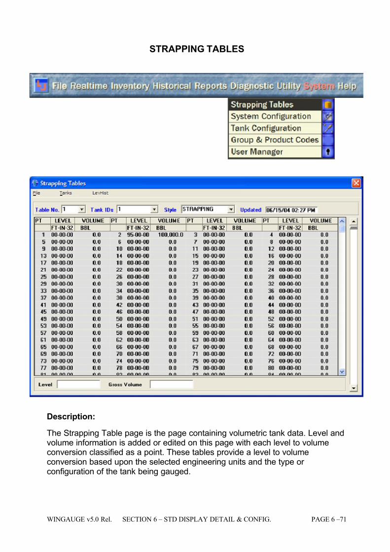
7/16/2019 3900 Manual
http://slidepdf.com/reader/full/3900-manual 119/266
WINGAUGE v5.0 Rel. SECTION 6 – STD DISPLAY DETAIL & CONFIG. PAGE 6 –71
STRAPPING TABLES
Description:
The Strapping Table page is the page containing volumetric tank data. Level andvolume information is added or edited on this page with each level to volumeconversion classified as a point. These tables provide a level to volumeconversion based upon the selected engineering units and the type or configuration of the tank being gauged.
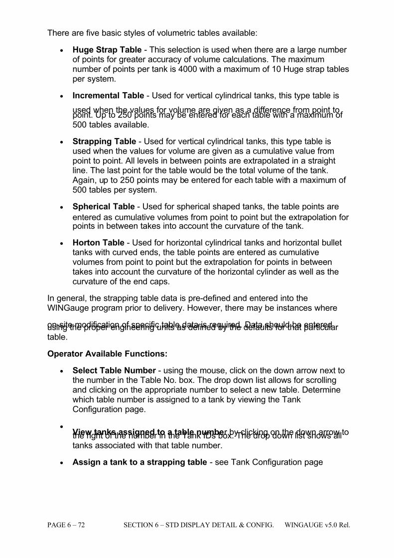
7/16/2019 3900 Manual
http://slidepdf.com/reader/full/3900-manual 120/266
PAGE 6 – 72 SECTION 6 – STD DISPLAY DETAIL & CONFIG. WINGAUGE v5.0 Rel.
There are five basic styles of volumetric tables available:
• Huge Strap Table - This selection is used when there are a large number of points for greater accuracy of volume calculations. The maximumnumber of points per tank is 4000 with a maximum of 10 Huge strap tablesper system.
• Incremental Table - Used for vertical cylindrical tanks, this type table is
used when the values for volume are given as a difference from point topoint. Up to 250 points may be entered for each table with a maximum of 500 tables available.
• Strapping Table - Used for vertical cylindrical tanks, this type table isused when the values for volume are given as a cumulative value frompoint to point. All levels in between points are extrapolated in a straightline. The last point for the table would be the total volume of the tank.
Again, up to 250 points may be entered for each table with a maximum of 500 tables per system.
• Spherical Table - Used for spherical shaped tanks, the table points are
entered as cumulative volumes from point to point but the extrapolation for points in between takes into account the curvature of the tank.
• Horton Table - Used for horizontal cylindrical tanks and horizontal bullettanks with curved ends, the table points are entered as cumulativevolumes from point to point but the extrapolation for points in betweentakes into account the curvature of the horizontal cylinder as well as thecurvature of the end caps.
In general, the strapping table data is pre-defined and entered into theWINGauge program prior to delivery. However, there may be instances where
on-site modification of specific table data is required. Data should be enteredusing the proper engineering units as defined by the defaults for that particular table.
Operator Available Functions:
• Select Table Number - using the mouse, click on the down arrow next tothe number in the Table No. box. The drop down list allows for scrollingand clicking on the appropriate number to select a new table. Determinewhich table number is assigned to a tank by viewing the TankConfiguration page.
•
View tanks assigned to a table number by clicking on the down arrow tothe right of the number in the Tank IDs box. The drop down list shows alltanks associated with that table number.
• Assign a tank to a strapping table - see Tank Configuration page
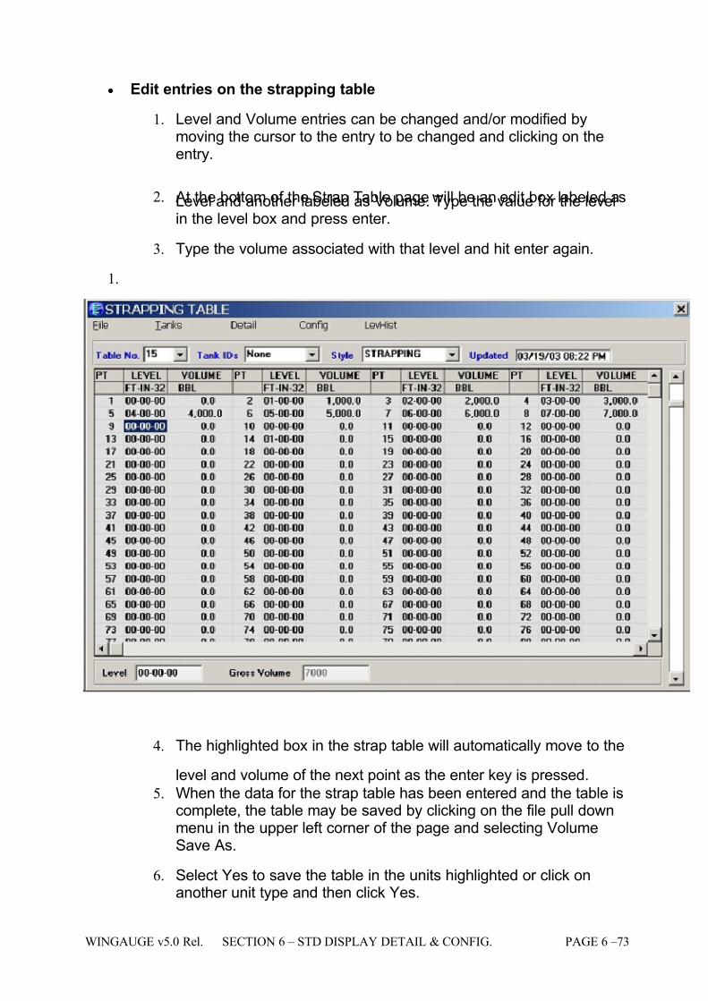
7/16/2019 3900 Manual
http://slidepdf.com/reader/full/3900-manual 121/266
WINGAUGE v5.0 Rel. SECTION 6 – STD DISPLAY DETAIL & CONFIG. PAGE 6 –73
• Edit entries on the strapping table
1. Level and Volume entries can be changed and/or modified bymoving the cursor to the entry to be changed and clicking on theentry.
2. At the bottom of the Strap Table page will be an edit box labeled asLevel and another labeled as Volume. Type the value for the levelin the level box and press enter.
3. Type the volume associated with that level and hit enter again.
1.
4. The highlighted box in the strap table will automatically move to the
level and volume of the next point as the enter key is pressed.
5. When the data for the strap table has been entered and the table iscomplete, the table may be saved by clicking on the file pull downmenu in the upper left corner of the page and selecting VolumeSave As.
6. Select Yes to save the table in the units highlighted or click onanother unit type and then click Yes.
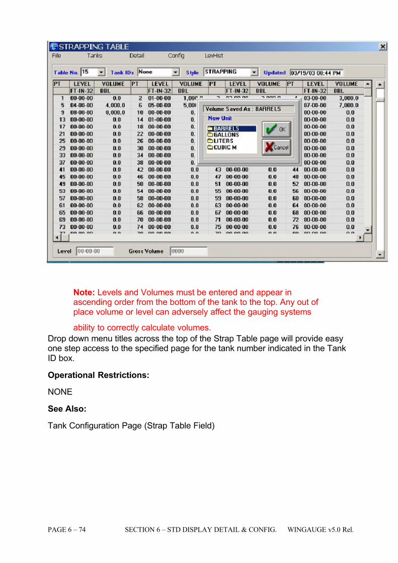
7/16/2019 3900 Manual
http://slidepdf.com/reader/full/3900-manual 122/266
PAGE 6 – 74 SECTION 6 – STD DISPLAY DETAIL & CONFIG. WINGAUGE v5.0 Rel.
Note: Levels and Volumes must be entered and appear inascending order from the bottom of the tank to the top. Any out of place volume or level can adversely affect the gauging systems
ability to correctly calculate volumes.
Drop down menu titles across the top of the Strap Table page will provide easyone step access to the specified page for the tank number indicated in the TankID box.
Operational Restrictions:
NONE
See Also:
Tank Configuration Page (Strap Table Field)
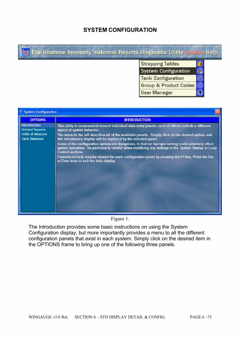
7/16/2019 3900 Manual
http://slidepdf.com/reader/full/3900-manual 123/266
WINGAUGE v5.0 Rel. SECTION 6 – STD DISPLAY DETAIL & CONFIG. PAGE 6 –75
SYSTEM CONFIGURATION
Figure 1.
The Introduction provides some basic instructions on using the SystemConfiguration display, but more importantly provides a menu to all the differentconfiguration panels that exist in each system. Simply click on the desired item inthe OPTIONS frame to bring up one of the following three panels.
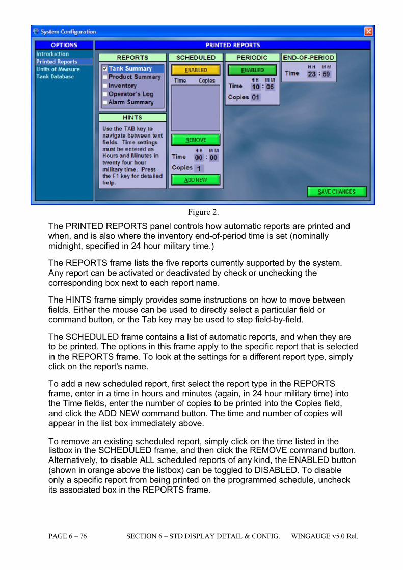
7/16/2019 3900 Manual
http://slidepdf.com/reader/full/3900-manual 124/266
PAGE 6 – 76 SECTION 6 – STD DISPLAY DETAIL & CONFIG. WINGAUGE v5.0 Rel.
Figure 2.
The PRINTED REPORTS panel controls how automatic reports are printed andwhen, and is also where the inventory end-of-period time is set (nominallymidnight, specified in 24 hour military time.)
The REPORTS frame lists the five reports currently supported by the system. Any report can be activated or deactivated by check or unchecking thecorresponding box next to each report name.
The HINTS frame simply provides some instructions on how to move betweenfields. Either the mouse can be used to directly select a particular field or command button, or the Tab key may be used to step field-by-field.
The SCHEDULED frame contains a list of automatic reports, and when they areto be printed. The options in this frame apply to the specific report that is selectedin the REPORTS frame. To look at the settings for a different report type, simplyclick on the report's name.
To add a new scheduled report, first select the report type in the REPORTSframe, enter in a time in hours and minutes (again, in 24 hour military time) intothe Time fields, enter the number of copies to be printed into the Copies field,and click the ADD NEW command button. The time and number of copies willappear in the list box immediately above.
To remove an existing scheduled report, simply click on the time listed in thelistbox in the SCHEDULED frame, and then click the REMOVE command button.
Alternatively, to disable ALL scheduled reports of any kind, the ENABLED button(shown in orange above the listbox) can be toggled to DISABLED. To disableonly a specific report from being printed on the programmed schedule, uncheckits associated box in the REPORTS frame.
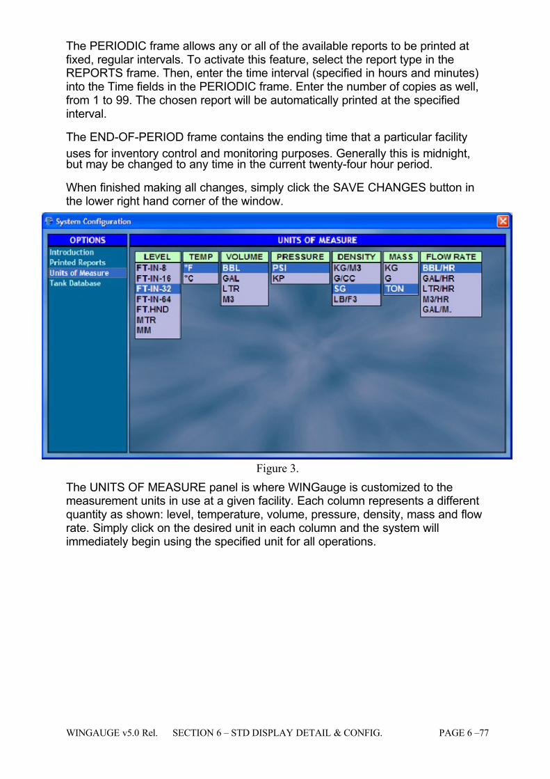
7/16/2019 3900 Manual
http://slidepdf.com/reader/full/3900-manual 125/266
WINGAUGE v5.0 Rel. SECTION 6 – STD DISPLAY DETAIL & CONFIG. PAGE 6 –77
The PERIODIC frame allows any or all of the available reports to be printed atfixed, regular intervals. To activate this feature, select the report type in theREPORTS frame. Then, enter the time interval (specified in hours and minutes)into the Time fields in the PERIODIC frame. Enter the number of copies as well,from 1 to 99. The chosen report will be automatically printed at the specifiedinterval.
The END-OF-PERIOD frame contains the ending time that a particular facility
uses for inventory control and monitoring purposes. Generally this is midnight,but may be changed to any time in the current twenty-four hour period.
When finished making all changes, simply click the SAVE CHANGES button inthe lower right hand corner of the window.
Figure 3.
The UNITS OF MEASURE panel is where WINGauge is customized to themeasurement units in use at a given facility. Each column represents a differentquantity as shown: level, temperature, volume, pressure, density, mass and flowrate. Simply click on the desired unit in each column and the system willimmediately begin using the specified unit for all operations.
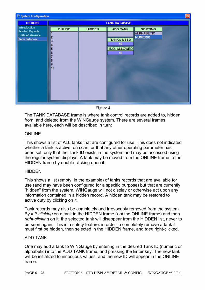
7/16/2019 3900 Manual
http://slidepdf.com/reader/full/3900-manual 126/266
PAGE 6 – 78 SECTION 6 – STD DISPLAY DETAIL & CONFIG. WINGAUGE v5.0 Rel.
Figure 4.
The TANK DATABASE frame is where tank control records are added to, hiddenfrom, and deleted from the WINGauge system. There are several framesavailable here, each will be described in turn:
ONLINE
This shows a list of ALL tanks that are configured for use. This does not indicatedwhether a tank is active, on scan, or that any other operating parameter hasbeen set, only that the Tank ID exists in the system and may be accessed usingthe regular system displays. A tank may be moved from the ONLINE frame to theHIDDEN frame by double-clicking upon it.
HIDDEN
This shows a list (empty, in the example) of tanks records that are available for use (and may have been configured for a specific purpose) but that are currently"hidden" from the system. WINGauge will not display or otherwise act upon anyinformation contained in a hidden record. A hidden tank may be restored toactive duty by clicking on it.
Tank records may also be completely and irrevocably removed from the system.By left-clicking on a tank in the HIDDEN frame (not the ONLINE frame) and thenright-clicking on it, the selected tank will disappear from the HIDDEN list, never to
be seen again. This is a safety feature: in order to completely remove a tank itmust first be hidden, then selected in the HIDDEN frame, and then right-clicked.
ADD TANK
One may add a tank to WINGauge by entering in the desired Tank ID (numeric or alphabetic) into the ADD TANK frame, and pressing the Enter key. The new tankwill be initialized to innocuous values, and the new ID will appear in the ONLINEframe.
7/16/2019 3900 Manual
http://slidepdf.com/reader/full/3900-manual 127/266
WINGAUGE v5.0 Rel. SECTION 6 – STD DISPLAY DETAIL & CONFIG. PAGE 6 –79
TANKS USED
This frame shows the total number of tanks available for use. This is the same asthe number of items in the ONLINE frame, ten (10) in Figure 4.
MAX. ALLOWED
This is the maximum of tanks that may be added to the system, and includesboth ONLINE and HIDDEN tank records, ten (10) as shown in Figure 4.. An
attempt to add more than this number of tanks to the system will simply beignored.
Operational Restrictions:
NONE
See Also:
N/A
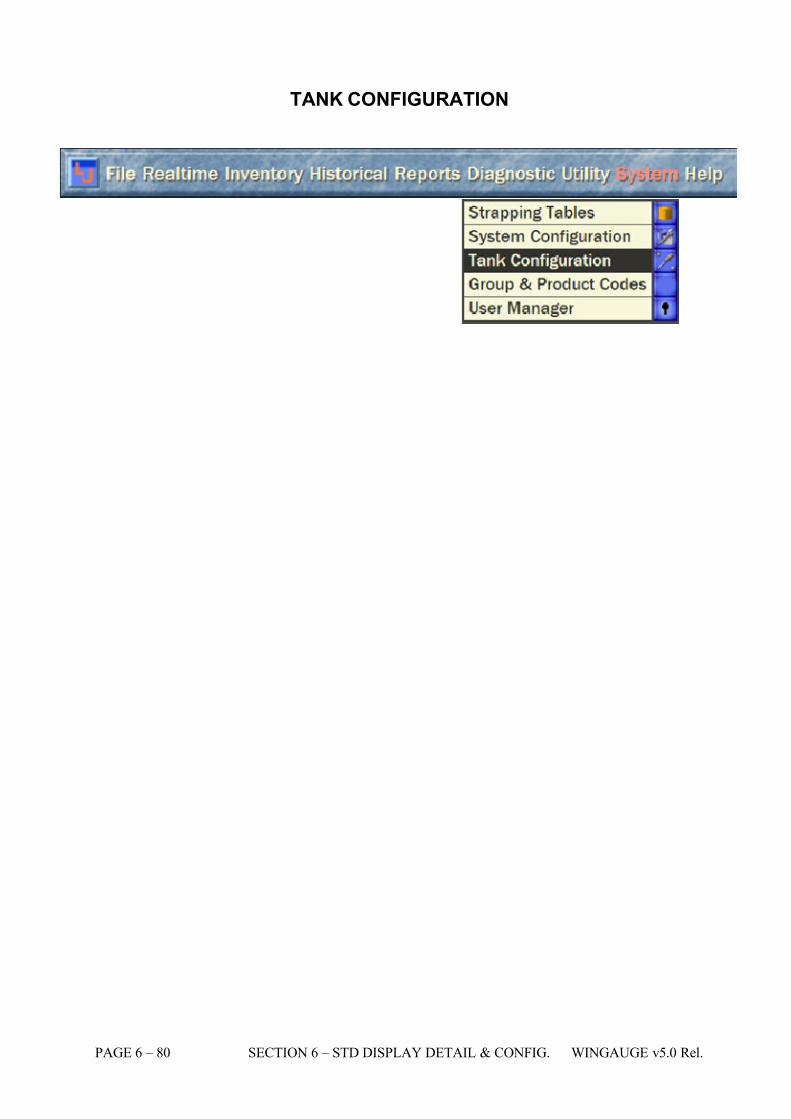
7/16/2019 3900 Manual
http://slidepdf.com/reader/full/3900-manual 128/266
PAGE 6 – 80 SECTION 6 – STD DISPLAY DETAIL & CONFIG. WINGAUGE v5.0 Rel.
TANK CONFIGURATION
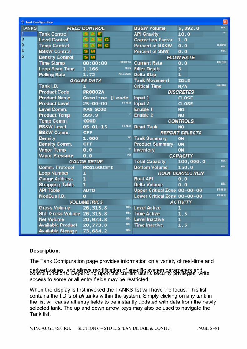
7/16/2019 3900 Manual
http://slidepdf.com/reader/full/3900-manual 129/266
WINGAUGE v5.0 Rel. SECTION 6 – STD DISPLAY DETAIL & CONFIG. PAGE 6 –81
Description:
The Tank Configuration page provides information on a variety of real-time and
derived values, and allows modification of specific system parameters andcontrol functions. Depending upon the current user's security privileges, writeaccess to some or all entry fields may be restricted.
When the display is first invoked the TANKS list will have the focus. This listcontains the I.D.'s of all tanks within the system. Simply clicking on any tank inthe list will cause all entry fields to be instantly updated with data from the newlyselected tank. The up and down arrow keys may also be used to navigate theTank list.
7/16/2019 3900 Manual
http://slidepdf.com/reader/full/3900-manual 130/266
PAGE 6 – 82 SECTION 6 – STD DISPLAY DETAIL & CONFIG. WINGAUGE v5.0 Rel.
The Tab key is used to move between fields. Pressing the Tab key will move thefocus highlight to the next field in the tab order: pressing Shift-Tab (hold down theShift and the Tab key simultaneously) will move the highlight to the previous field.
If the user attempts to modify the contents of any entry field without authorization,the User Log-In window will be automatically displayed. The same will happen if there is no active login.
Operator Available Functions:
# Legend Operations Where Set Access
1 API Gravity
Description
Gravity (weight per unit of volume) of crude oil or other liquid hydrocarbons as measured by a systemrecommended by the American Petroleum Institute.Simply enter a value into this field and the system willautomatically begin to calculate volumes based uponthe new entry. Valid API values range from -37 to 340.
Usage
Open any of the listed pages in the Where Set columnfor this field and select the tank whose value is to bemodified. Either click directly upon the API Gravityfield, or use the Tab key to navigate to the field. Typethe new API Gravity value.
Impact
The entered API Gravity affects the calculated APIcorrection factor, which in turn affects the derived NetVolume value and available product values.
NOTE: If you do not have a valid remote temperaturevalue, and/or have not entered a manual temperature,the system will automatically set the internal correctionfactor to 1 regardless of the API Table setting or thedisplayed API value. This effectively references thesystem to 60 degrees Fahrenheit, which is standard for most API calculations.
See the Temp Control and the Product Temp fielddescriptions below for more information on sett ing amanual temperature, and the behavior of the producttemperature display field under fault conditions.
Tank Configuration Tank Detail
Admin
Super
2 API Table
Description
The API Table setting instructs the system to use aspecific internal data table to calculate a volumecorrection factor. These tables are standard tables asdefined by the American Petroleum Institute. Note: If atank has API Table set to AUTO, the system analyzesthe system engineering units and chooses theappropriate API Table (54A,B,C for Metric units, 6A,B,Cfor non-metric units).The following are the currentlyavailable API table settings:
AUTO 24B
6A 6
6B 54A
6C 54B
24 54C
24A 34
Usage
Open any of the listed pages in the Where Set columnfor this field and select the tank whose value is to bemodified. Click on the API Table field: a dropdown listof the available API tables will appear. Choose thedesired table from the list: the system willautomatically save the selection and will continuegauging using the new table.
Tank Configuration Admin
7/16/2019 3900 Manual
http://slidepdf.com/reader/full/3900-manual 131/266
WINGAUGE v5.0 Rel. SECTION 6 – STD DISPLAY DETAIL & CONFIG. PAGE 6 –83
# Legend Operations Where Set Access
Impact The choice of API table affects the calculated APIcorrection factor, which in turn affects the derived NetVolume value and available product.
3 AvailableProduct
Description
The volume of product actually available from the tank.This value is calculated by taking the bottom valueentered by the end user and subtracting it from the NetVolume. This value is not editable by the end user, butproper temperature and gravity values are required for the system to accurately derive Net Volume. This valueis automatically updated by the system whenever anymeasured or entered values change.
Usage This is a display-only field and cannot be edited. Impact Available Product = (Net Volume - Bottom Volume)
... ...
4 AvailableStorage
Description
The volume of unused space available in the tank. Thisvalue is calculated by taking the Total Tank Capacityentered by the end user and subtracting the GrossVolume derived from the strapping table for the currenttank level. The value is not editable but will change asproduct level moves or if Total Capacity Valuechanges.
Usage This is a display-only field and cannot be edited. Definition (Total Volume - Gross Volume)
... ...
5 BottomVolume
Description
The volume at the bottom of the tank that is normallynot available. This will normally be the product levelbelow the suction line connected to the tank which thepump cannot access.
Usage
Open any of the listed pages in the Where Set columnfor this field and select the tank whose value is to bemodified. Either click directly upon the Bottom Volumefield, or use the Tab key to navigate to the field. Typethe new Bottom Volume value. The value is entered inthe system units chosen for Volume.
Impact The Bottom Volume value is used in the AvailableProduct calculation.
Tank Configuration ...
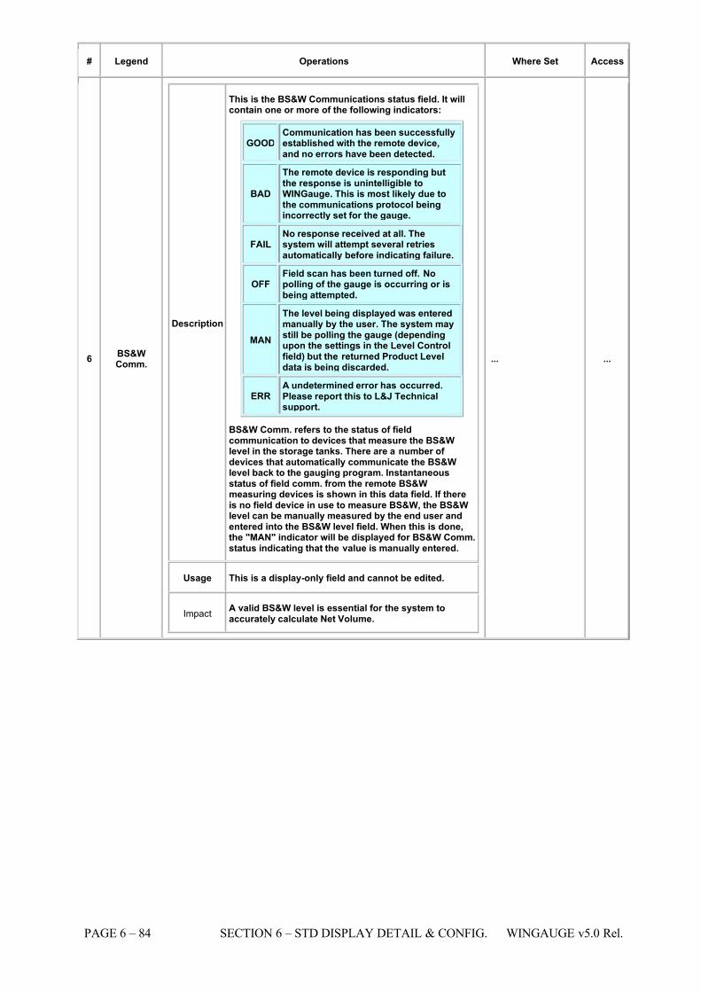
7/16/2019 3900 Manual
http://slidepdf.com/reader/full/3900-manual 132/266
PAGE 6 – 84 SECTION 6 – STD DISPLAY DETAIL & CONFIG. WINGAUGE v5.0 Rel.
# Legend Operations Where Set Access
6 BS&WComm.
Description
This is the BS&W Communications status field. It willcontain one or more of the following indicators:
GOOD Communication has been successfullyestablished with the remote device,and no errors have been detected.
BAD
The remote device is responding butthe response is unintelligible toWINGauge. This is most likely due tothe communications protocol beingincorrectly set for the gauge.
FAIL No response received at all. Thesystem will attempt several retriesautomatically before indicating failure.
OFF Field scan has been turned off. Nopolling of the gauge is occurring or isbeing attempted.
MAN
The level being displayed was enteredmanually by the user. The system maystill be polling the gauge (dependingupon the settings in the Level Controlfield) but the returned Product Leveldata is being discarded.
ERR A undetermined error has occurred.Please report this to L&J Technicalsupport.
BS&W Comm. refers to the status of fieldcommunication to devices that measure the BS&Wlevel in the storage tanks. There are a number of devices that automatically communicate the BS&Wlevel back to the gauging program. Instantaneousstatus of field comm. from the remote BS&Wmeasuring devices is shown in this data field. If thereis no field device in use to measure BS&W, the BS&Wlevel can be manually measured by the end user andentered into the BS&W level field. When this is done,the "MAN" indicator will be displayed for BS&W Comm.status indicating that the value is manually entered.
Usage This is a display-only field and cannot be edited.
ImpactA valid BS&W level is essential for the system toaccurately calculate Net Volume.
... ...
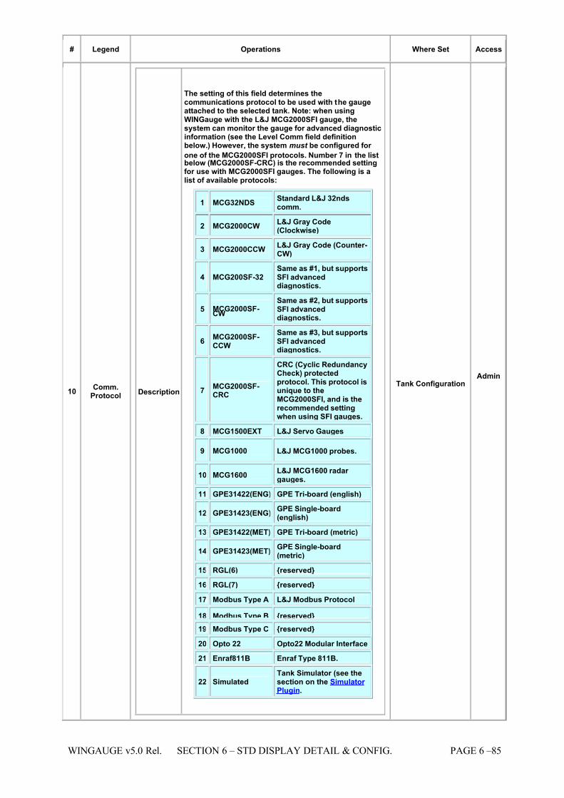
7/16/2019 3900 Manual
http://slidepdf.com/reader/full/3900-manual 133/266
WINGAUGE v5.0 Rel. SECTION 6 – STD DISPLAY DETAIL & CONFIG. PAGE 6 –85
# Legend Operations Where Set Access
10 Comm.Protocol Description
The setting of this field determines thecommunications protocol to be used with the gaugeattached to the selected tank. Note: when usingWINGauge with the L&J MCG2000SFI gauge, thesystem can monitor the gauge for advanced diagnosticinformation (see the Level Comm field definitionbelow.) However, the system must be configured for
one of the MCG2000SFI protocols. Number 7 in the listbelow (MCG2000SF-CRC) is the recommended settingfor use with MCG2000SFI gauges. The following is alist of available protocols:
1 MCG32NDS Standard L&J 32ndscomm.
2 MCG2000CW L&J Gray Code(Clockwise)
3 MCG2000CCW L&J Gray Code (Counter-CW)
4 MCG200SF-32 Same as #1, but supportsSFI advanceddiagnostics.
5 MCG2000SF-CW
Same as #2, but supportsSFI advanceddiagnostics.
6 MCG2000SF-CCW
Same as #3, but supportsSFI advanceddiagnostics.
7 MCG2000SF-CRC
CRC (Cyclic RedundancyCheck) protectedprotocol. This protocol isunique to theMCG2000SFI, and is therecommended settingwhen using SFI gauges.
8 MCG1500EXT L&J Servo Gauges
9 MCG1000 L&J MCG1000 probes.
10 MCG1600 L&J MCG1600 radar gauges.
11 GPE31422(ENG) GPE Tri-board (english)
12 GPE31423(ENG)GPE Single-board(english)
13 GPE31422(MET) GPE Tri-board (metric)
14 GPE31423(MET)GPE Single-board(metric)
15 RGL(6) {reserved}
16 RGL(7) {reserved}
17 Modbus Type A L&J Modbus Protocol
18 Modbus Type B {reserved} 19 Modbus Type C {reserved}
20 Opto 22 Opto22 Modular Interface
21 Enraf811B Enraf Type 811B.
22 Simulated Tank Simulator (see thesection on the Simulator Plugin.
Tank Configuration Admin
7/16/2019 3900 Manual
http://slidepdf.com/reader/full/3900-manual 134/266
PAGE 6 – 86 SECTION 6 – STD DISPLAY DETAIL & CONFIG. WINGAUGE v5.0 Rel.
# Legend Operations Where Set Access
Usage
Open any of the listed pages in the Where Set columnfor this field and select the tank whose value is to bemodified. Click on the Comm Protocol field: adropdown list of the available protocols wil l appear.Choose the desired protocol from the list: the systemwill automatically save the selection and will continuegauging using the new protocol. Note that the updatedselection will not take effect until the Advanced
Gauging Module has completed polling on the affectedloop. For all L&J SFI series field devices, the protocolcan be set to a variety of different styles. Verify theprogramming of the SFI Transmitter to ensure thecomm. protocol is programmed as desired.
Impact
Many gauges support multiple protocols, and validdata will not be received if WINGauge and the gaugeare configured for incompatible protocols. The correctcomm. protocol will normally be programmed by L&Jprior to shipment of the system. It is imperative that theproper Comm. protocol be selected to match the fielddevice protocol. If it is not, incorrect or no data at allwill result for level and temperature information. If theuser cannot find the proper communication protocol inthe provided list of the gauging program, they shouldconsult L&J Technical support before attempting any
system configuration.
11 CorrectionFactor
Description
API volume correction factor (1.0 @ 60 DEG .F). Thisvalue is unitless and is a system calculated valuebased on the product temperature as well as the APItable chosen in the system configuration page. In themajority of cases, the system should be set to AUTOfor API table selection. This will allow the gaugingprogram to automatically select the proper API tablefor the given gravity and temperature.
Usage This is a display-only field and cannot be edited.
Impact
Proper Correction factor calculations are imperative for
accurate Net Volume Calculations throughout thesystem. User should verify regularly that proper product temperature and gravity are available in thesystem for each tank to ensure accurate correctionfactors as well as Net Volume Calculations.
... ...
7/16/2019 3900 Manual
http://slidepdf.com/reader/full/3900-manual 135/266
WINGAUGE v5.0 Rel. SECTION 6 – STD DISPLAY DETAIL & CONFIG. PAGE 6 –87
# Legend Operations Where Set Access
14 CriticalTime
Description
Given that a tank is in motion and that a flow rate hasbeen detected, Critical Time is defined as the timeremaining for the product level to reach the high alarmlevel (if the tank is filling) or the low alarm level (if thetank is emptying.) The software automaticallydetermines the correct level to use from the directionof flow.
The calculated value for Critical Time is based uponthe current flow rate, current gross volume, and theprogrammed alarm level (after conversion to thecorresponding volume.) During each update cycle, thedifference between the current volume and theapplicable alarm volume is divided by the flow rate togive Critical Time. Critical Time is viewed on-screen ashours and minutes (hhh:mm). It appears as a data fieldon Tank Detail page (see example below), theFastGauge display, and as a user-selectable columnoption in the Tank Groups display. It is also availableas a display field in the Dynamic Forms Generator.
In all cases, if a tank is not in motion (no level change)and/or the flow rate is zero, the symbol "N/A" (NotAvailable) will appear instead of a Critical Time value.The target values for Critical Time are specified here,via the High High, Hi-Hi, Low and Low-Low level alarm
set points.
In this example, the High Level set point (7.106 meters)corresponds to 4000 barrels of product in thisparticular tank. Likewise, the Low Level value of 3.549meters indicates a volume of 2000 barrels of product.When the Critical Time displays as zero, one of theselevels has been reached. The Critical Time value shownin the preceding example is ten hours, zero minutes.This number was determined via the following simplecalculation: Gross Volume = 3000 barrels Flow Rate =100 barrels per hour High Alarm = 7.106 meters or 4000barrels. Critical Time = (4000 - 3000) / 100, or 10 hours.
Usage This is a display-only field and cannot be edited.
Impact Allows user instant access to time remaining beforehigh or low alarm limits is exceeded, based upon the
current flow rate.
... ...
15 CurrentRate
Description
This is the rate (displayed in the rate units specified onthe System Configuration page) at which product isflowing in or out of a tank. If the displayed number ispositive, product is flowing into the tank. If the number is negative, product is leaving the tank. This number isnot based upon actual flow measurements, but isderived from the change in product volume over time.
The volume change is calculated by the amount of level change detected each minute and thecorresponding volume change derived from the tankstrapping table.
Usage This is a display-only field and cannot be edited.
Impact
An accurate current rate value is essential for thesystem to calculate an accurate critical time. Thisallows the user to see how long it will take to reach ahigh or low alarm point at the current Rate of flow.Level active/inactive and time active/inactiveparameters must be set correctly for the system todetect that a tank is active.
... ...
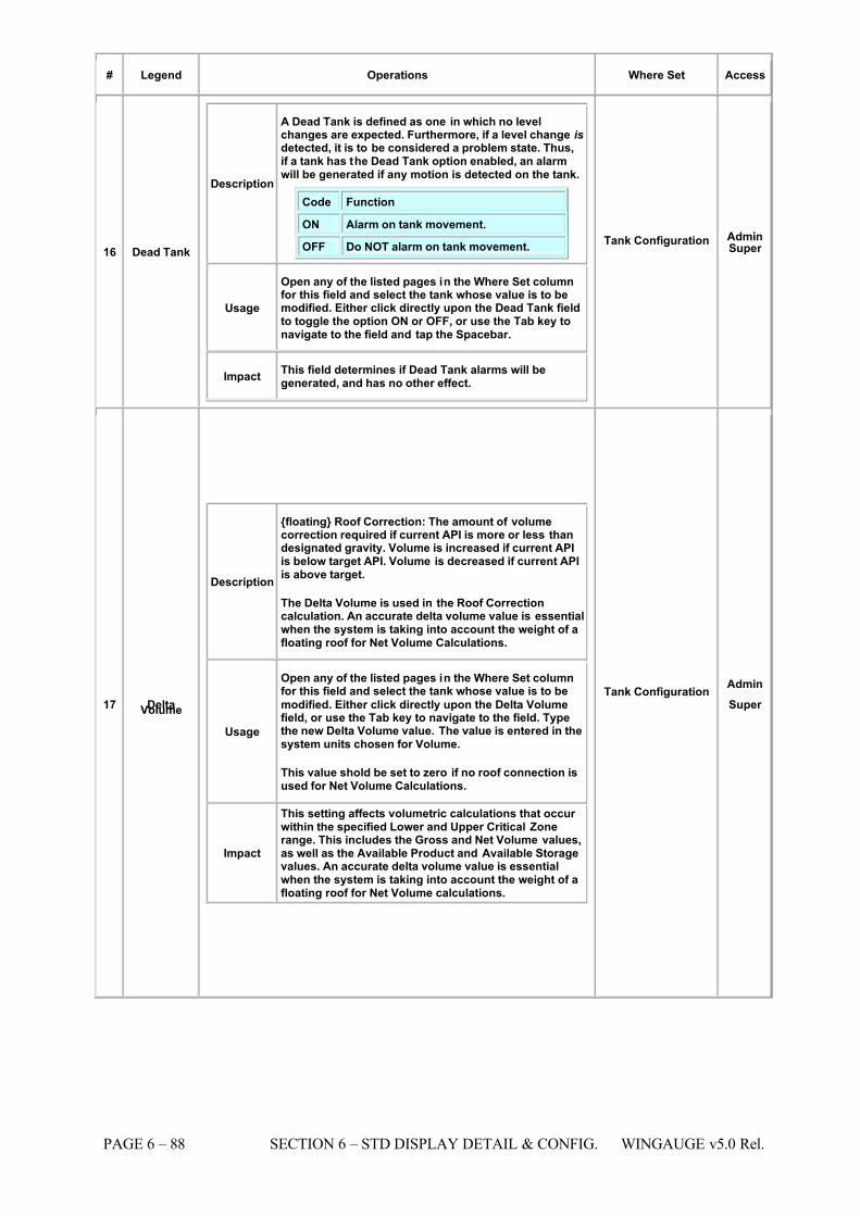
7/16/2019 3900 Manual
http://slidepdf.com/reader/full/3900-manual 136/266
PAGE 6 – 88 SECTION 6 – STD DISPLAY DETAIL & CONFIG. WINGAUGE v5.0 Rel.
# Legend Operations Where Set Access
16 Dead Tank
Description
A Dead Tank is defined as one in which no levelchanges are expected. Furthermore, if a level change isdetected, it is to be considered a problem state. Thus,if a tank has the Dead Tank option enabled, an alarmwill be generated if any motion is detected on the tank.
Code Function
ON
Alarm on tank movement.
OFF Do NOT alarm on tank movement.
Usage
Open any of the listed pages in the Where Set columnfor this field and select the tank whose value is to bemodified. Either click directly upon the Dead Tank fieldto toggle the option ON or OFF, or use the Tab key tonavigate to the field and tap the Spacebar.
Impact This field determines if Dead Tank alarms will begenerated, and has no other effect.
Tank Configuration AdminSuper
17 DeltaVolume
Description
{floating} Roof Correction: The amount of volumecorrection required if current API is more or less thandesignated gravity. Volume is increased if current APIis below target API. Volume is decreased if current APIis above target.
The Delta Volume is used in the Roof Correctioncalculation. An accurate delta volume value is essentialwhen the system is taking into account the weight of afloating roof for Net Volume Calculations.
Usage
Open any of the listed pages in the Where Set columnfor this field and select the tank whose value is to be
modified. Either click directly upon the Delta Volumefield, or use the Tab key to navigate to the field. Typethe new Delta Volume value. The value is entered in thesystem units chosen for Volume.
This value shold be set to zero if no roof connection isused for Net Volume Calculations.
Impact
This setting affects volumetric calculations that occur within the specified Lower and Upper Critical Zonerange. This includes the Gross and Net Volume values,as well as the Available Product and Available Storagevalues. An accurate delta volume value is essentialwhen the system is taking into account the weight of afloating roof for Net Volume calculations.
Tank Configuration Admin
Super
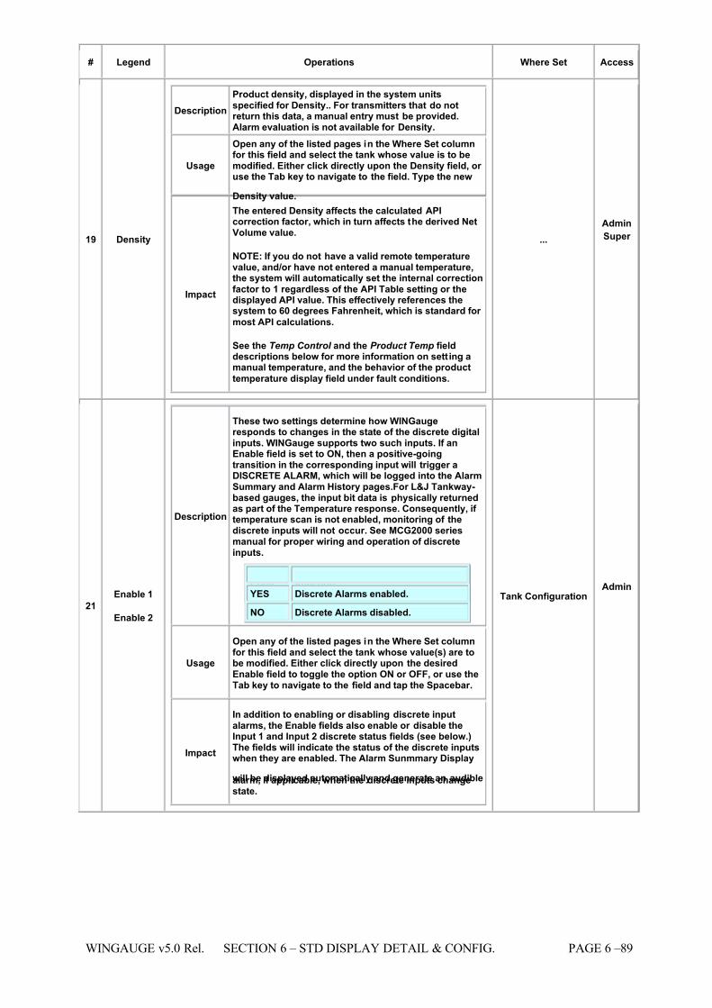
7/16/2019 3900 Manual
http://slidepdf.com/reader/full/3900-manual 137/266
WINGAUGE v5.0 Rel. SECTION 6 – STD DISPLAY DETAIL & CONFIG. PAGE 6 –89
# Legend Operations Where Set Access
19 Density
Description Product density, displayed in the system unitsspecified for Density.. For transmitters that do notreturn this data, a manual entry must be provided.Alarm evaluation is not available for Density.
Usage
Open any of the listed pages in the Where Set columnfor this field and select the tank whose value is to bemodified. Either click directly upon the Density field, or use the Tab key to navigate to the field. Type the new
Density value.
Impact
The entered Density affects the calculated APIcorrection factor, which in turn affects the derived NetVolume value.
NOTE: If you do not have a valid remote temperaturevalue, and/or have not entered a manual temperature,the system will automatically set the internal correctionfactor to 1 regardless of the API Table setting or thedisplayed API value. This effectively references thesystem to 60 degrees Fahrenheit, which is standard for
most API calculations.
See the Temp Control and the Product Temp fielddescriptions below for more information on sett ing amanual temperature, and the behavior of the product
temperature display field under fault conditions.
... Admin
Super
21 Enable 1
Enable 2
Description
These two settings determine how WINGaugeresponds to changes in the state of the discrete digitalinputs. WINGauge supports two such inputs. If anEnable field is set to ON, then a positive-goingtransition in the corresponding input will trigger aDISCRETE ALARM, which will be logged into the AlarmSummary and Alarm History pages.For L&J Tankway-based gauges, the input bit data is physically returnedas part of the Temperature response. Consequently, if temperature scan is not enabled, monitoring of thediscrete inputs will not occur. See MCG2000 seriesmanual for proper wiring and operation of discreteinputs.
Code Function YES Discrete Alarms enabled.
NO Discrete Alarms disabled.
Usage
Open any of the listed pages in the Where Set columnfor this field and select the tank whose value(s) are tobe modified. Either click directly upon the desiredEnable field to toggle the option ON or OFF, or use theTab key to navigate to the field and tap the Spacebar.
Impact
In addition to enabling or disabling discrete inputalarms, the Enable fields also enable or disable theInput 1 and Input 2 discrete status fields (see below.)The fields will indicate the status of the discrete inputswhen they are enabled. The Alarm Sunmmary Display
will be displayed automatically and generate an audiblealarm, if applicable, when the discrete inputs changestate.
Tank Configuration Admin
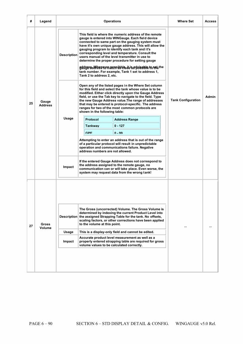
7/16/2019 3900 Manual
http://slidepdf.com/reader/full/3900-manual 138/266
PAGE 6 – 90 SECTION 6 – STD DISPLAY DETAIL & CONFIG. WINGAUGE v5.0 Rel.
# Legend Operations Where Set Access
25 GaugeAddress
Description
This field is where the numeric address of the remotegauge is entered into WINGauge. Each field deviceconnected to same part on the gauging system musthave it's own unique gauge address. This will allow thegauging program to identify each tank and it'scorresponding level and temperature. Consult theusers manual of the level transmitter in use todetermine the proper procedure for setting gauge
address. Whenever possibble, it is advisable to set thegauge address to match as close as possible to thetank number. For example, Tank 1 set to address 1,
Tank 2 to address 2, etc.
Usage
Open any of the listed pages in the Where Set columnfor this field and select the tank whose value is to bemodified. Either click directly upon the Gauge Addressfield, or use the Tab key to navigate to the field. Typethe new Gauge Address value.The range of addressesthat may be entered is protocol-specific. The addressranges for two of the most common protocols areshown in the following table:
Protocol Address Range
Tankway 0 - 127
GPE 0 - 99 Attempting to enter an address that is out of the rangeof a particular protocol will result in unpredictableoperation and communications failure. Negativeaddress numbers are not allowed.
Impact If the entered Gauge Address does not correspond tothe address assigned to the remote gauge, nocommunication can or will take place. Even worse, thesystem may request data from the wrong tank!
Tank Configuration Admin
27 GrossVolume
Description
The Gross (uncorrected) Volume. The Gross Volume isdetermined by indexing the current Product Level intothe assigned Strapping Table for the tank. No offsets,scaling factors, or other corrections have been appliedto the volume at this point.
Usage This is a display-only field and cannot be edited.
ImpactAccurate product level measurement as well as aproperly entered strapping table are required for grossvolume values to be calculated correctly.
... ...
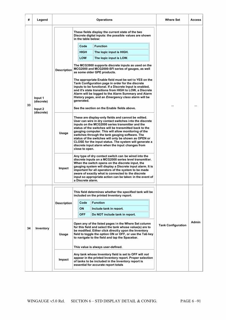
7/16/2019 3900 Manual
http://slidepdf.com/reader/full/3900-manual 139/266
WINGAUGE v5.0 Rel. SECTION 6 – STD DISPLAY DETAIL & CONFIG. PAGE 6 –91
# Legend Operations Where Set Access
33
Input 1(discrete)
Input 2(discrete)
Description
These fields display the current state of the twoDiscrete digital inputs: the possible values are shownin the table below:
Code Function
HIGH The logic input is HIGH.
LOW The logic input is LOW.
The MCG3900 supports discrete inputs as used on theMCG2000 and MCG2000-SFI series of gauges, as wellas some older GPE products.
The appropriate Enable field must be set to YES on theTank Configuration page in order for the discreteinputs to be functional. If a Discrete Input is enabled,and it's state transitions from HIGH to LOW, a DiscreteAlarm will be logged to the Alarm Summary and AlarmHistory pages, and an Emergency class alarm will begenerated.
See the section on the Enable fields above.
Usage
These are display-only fields and cannot be edited.User can wire in dry contact switches into the discreteinputs on the MCG2000 series transmitter and thestatus of the switches will be transmitted back to thegauging computer. This will allow monitoring of theswitches through the tank gauging software. Thestatus of the switches will only be shown as OPEN or CLOSE for the input status. The system will generate adiscrete input alarm when the input changes fromclose to open.
Impact
Any type of dry contact switch can be wired into thediscrete inputs on a MCG2000 series level transmitter.When the switch opens on the discrete input, thegauging system will display a Discrete input alarm. It isimportant for all operators of the system to be madeaware of exactly what is connected to the discreteinput so appropriate action can be taken in the event of a Discrete alarm.
... ...
34 Inventory
Description
This field determines whether the specified tank will beincluded on the printed Inventory report.
Code Function
ON Include tank in report.
OFF Do NOT include tank in report.
Usage
Open any of the listed pages in the Where Set columnfor this field and select the tank whose value(s) are tobe modified. Either click directly upon the Inventoryfield to toggle the option ON or OFF, or use the Tab keyto navigate to the field and tap the Spacebar.
This value is always user-defined.
Impact Any tank whose Inventory field is set to OFF will not appear in the printed Inventory report. Proper selectionof tanks to be included in the Inventory report isessential for accurate report totals
Tank Configuration Admin
7/16/2019 3900 Manual
http://slidepdf.com/reader/full/3900-manual 140/266
PAGE 6 – 92 SECTION 6 – STD DISPLAY DETAIL & CONFIG. WINGAUGE v5.0 Rel.
# Legend Operations Where Set Access
35 LevelActive
Description
The Level Active field works in conjunction with theTime Active field to determine whether a tank isACTIVE or INACTIVE. An active tank is one that is inmotion (i.e., experiencing a change in level.) Aninactive tank is one whose level is not changing.
In order for a tank to switch from the inactive state tothe active state, the level must change more than the
specified Level Active field within the specified TimeActive interval. For example: If the level active field isset to 5 and the time active field is set to 2, the systemwill consider the level active if the product levelchanges 5 or more sixteenths of an inch in 2 minutes.The tank will remain active as long as the levelcontinues to change at least 5 sixteenths every 2minutes. Level active parameters work the samewhether the tank level is going up or down.
Usage
Open any of the listed pages in the Where Set columnfor this field and select the tank whose value is to bemodified. Either click directly upon the Level Activefield, or use the Tab key to navigate to the field. Typethe new Level Active value. The value is entered in16ths of an inch.
This value is always user-defined.
Impact
The Level Active field affects all aspects of theprogram where tank activity is important. This includesthe Tank Movement field, the Active Tanks display, theDead Tank alarm, the Rate field, and the AutomaticData Exporter. User may have to try different active andinactive parameters on a per tank basis to find thecorrect valves that give best results.
Tank Configuration Admin
7/16/2019 3900 Manual
http://slidepdf.com/reader/full/3900-manual 141/266
WINGAUGE v5.0 Rel. SECTION 6 – STD DISPLAY DETAIL & CONFIG. PAGE 6 –93
# Legend Operations Where Set Access
36 LevelComm.
Description
This is the Level Communications status field. It willcontain one or more of the following indicators:
GOOD Communication has been successfullyestablished with the remote device,and no errors have been detected.
BAD
The remote device is responding butthe response is unintelligible toWINGauge. This is most likely due tothe communications protocol beingincorrectly set for the gauge.
FAIL No response received at all. Thesystem will attempt several retriesautomatically before indicating failure.
OFF Field scan has been turned off. Nopolling of the gauge is occurring or isbeing attempted.
MAN
The level being displayed was enteredmanually by the user. The system maystill be polling the gauge (dependingupon the settings in the Level Controlfield) but the returned Product Leveldata is being discarded.
UF This gauge has a SoftCal (SoftwareCalibration) applied, and an UnderFlowcondition has occurred.
CAL
A SoftCal has been applied, and theProduct Level is being offset by thespecified amount. This is not an error condition: it simply indicates thepresence of a SoftCal offset.
AMB
MCG200SFI-only: An Ambiguity Error has occurred. This condition occurswhen the gauge has detected anexcessive change in level. Thistypically happens when the encoder wheel's emitter or receiver hasmalfunctioned, or there is some other problem with the optics.
CA
MCG200SFI-only: A Cable Fault hasbeen detected. This indicates that thereis virtually no emitter current (generallythis occurs when the cable leadingfrom the internal circuit board to theencoded module has been unplugged.)
ECL MCG200SFI-only: The emitter currenthas dropped below the factory-programmed minimum value.
ECH MCG200SFI-only: The emitter currenthas exceeded the factory-programmedmaximum value.
ERR A undetermined error has occurred.Please report this to L&J Technicalsupport.
These values will give the user immediate status of every level transmitting device connected to the tankgauging system.
Usage This is a display-only field and cannot be edited.
Impact
Normal display for all tanks should show "GOOD". Anyother status indicator should be checked by the user toverify that the displayed level or temperature is correctand that no problems are occuring with the displyedvalues. If the user does not understand an status
Tank Configuration Tank Detail
Tank Summary ...
7/16/2019 3900 Manual
http://slidepdf.com/reader/full/3900-manual 142/266
PAGE 6 – 94 SECTION 6 – STD DISPLAY DETAIL & CONFIG. WINGAUGE v5.0 Rel.
# Legend Operations Where Set Access
indicator shown for level or temperature, they shouldimmediately report it to their supervisor for clarificationor rectification of the status indicator.
7/16/2019 3900 Manual
http://slidepdf.com/reader/full/3900-manual 143/266
WINGAUGE v5.0 Rel. SECTION 6 – STD DISPLAY DETAIL & CONFIG. PAGE 6 –95
# Legend Operations Where Set Access
37 LevelControl
Description
The Level Control field allows the user to toggle thefollowing real-time gauging parameters. There are four small light bulbs in this field, each containing a letter code corresponding to the function the bulb controls,as follows:
Code Function
S
Scan
A Alarm Evaluation
M Manual Entry
C Software Calibration (SoftCal)
When the bulb is lit, the function is enabled. When thebulb is dark, the function is disabled.
Usage
Open any of the listed pages in the Where Set columnfor this field and select the tank whose value is to bemodified. Click on (S)can bulb to toggle Level scanningon and off, click on the (A) bulb to turn AlarmEvaluation on or off, click on the (M) bulb to turnManual Entry mode on or off, or click on the "C" bulbto turn Software Calibration on or off. When the scan
bulb is lit, the gauging program will send out requeststo the level transmitter requesting it to send back level.The program will continuously send requests to thetank as long as the scan bulb is lit. If the scan bulb isnot lit, the gauging program will not send requests tothe level transmitter.
When the Alarm Evaluation bulb is lit, the system willprocess any level, temperature, rate, etc. alarms thatoccur for the tank. This includes opening the alarmsummary window as well as sounding the audiblealarm for any new alarms encountered. If the alarmevaluation bulb is not lit, the system will not processany alarm conditions that occur for the tank. The alarmcondition will be ignored by the system and no visualor audible indicators for the alarm condition will occur.If the manual entry bulb is lit, this indicates thedisplayed level was entered from the keyboard
manually and is not a level from a field transmitter. Thesystem will use this manually entered value for allcalculations for the tank. If the manual entry bulb is notlit, this indicates that the sytem will try to interogate afield transmitter for level provided that the scan bulb islit.
If the Software Calibration bulb is lit, this indicated thatthe displayed level has been offset by the user to reada level other than that received from the leveltransmitter.
If the transmitter is sending a level to the gaugingsystem of 12 feet 6 inches, but the user has determinedthat the actual level in the tank is 12 feet 3 inches, theSoft Calibration function can be used to make the levelread 12 feet 3 inches. This offset will be used for the
tank as long as the Software Calibration button is lit.
Impact
If Level scanning is disabled, the system will notattempt to acquire updated Level values from theremote gauge, and the Product Level and variousproduct volume fields will reflect the last known gooddata. If level scan is disabled and the last known levelis not a good value, a manual entry should be used for product level. If level scan and manual entry areenabled at the same time, the manually entered levelwill be used by the system. The gauging system willstill scan the tank for product level but the returnedlevel will not be used until the manual entry is disabled.
Tank Configuration Tank Detail
Admin
Super
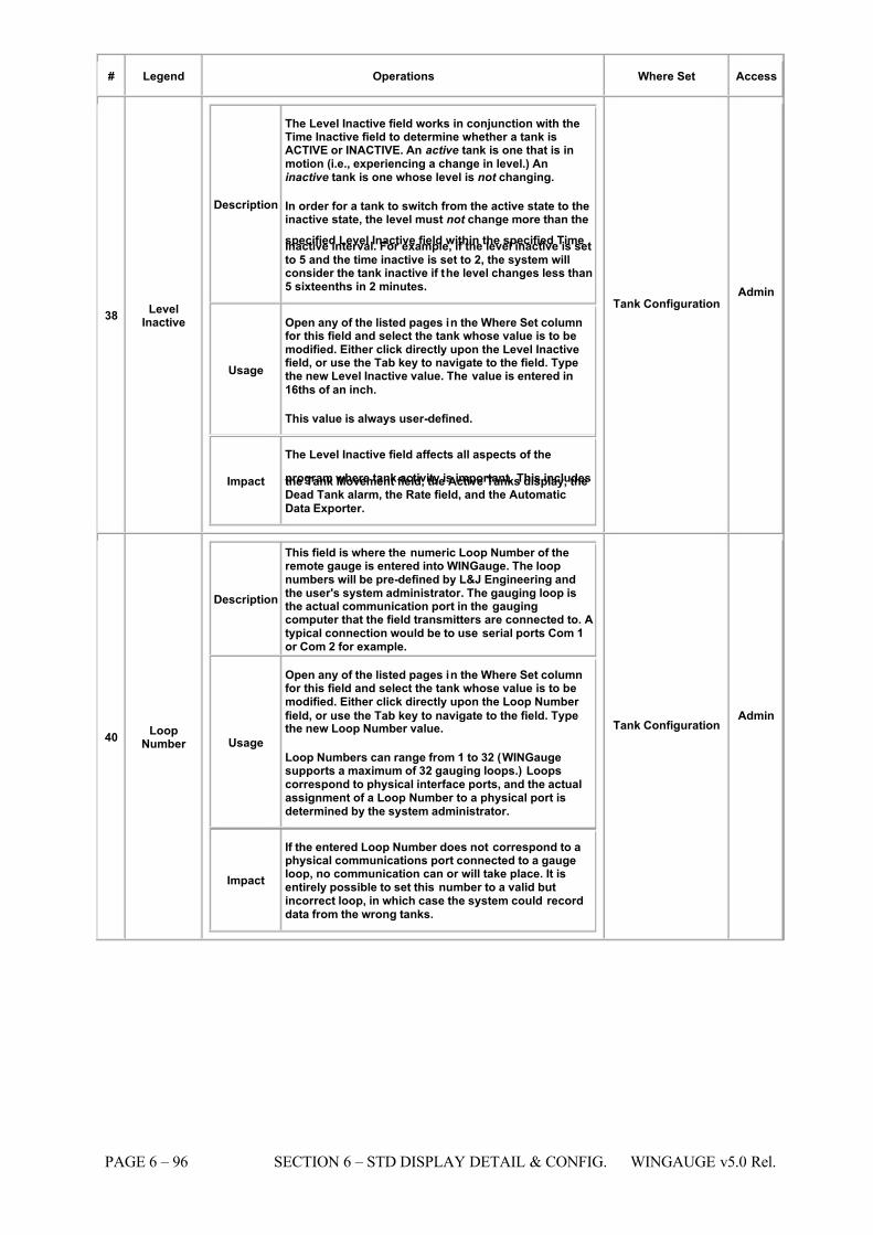
7/16/2019 3900 Manual
http://slidepdf.com/reader/full/3900-manual 144/266
PAGE 6 – 96 SECTION 6 – STD DISPLAY DETAIL & CONFIG. WINGAUGE v5.0 Rel.
# Legend Operations Where Set Access
38 LevelInactive
Description
The Level Inactive field works in conjunction with theTime Inactive field to determine whether a tank isACTIVE or INACTIVE. An active tank is one that is inmotion (i.e., experiencing a change in level.) Aninactive tank is one whose level is not changing.
In order for a tank to switch from the active state to theinactive state, the level must not change more than the
specified Level Inactive field within the specified TimeInactive interval. For example, if the level inactive is setto 5 and the time inactive is set to 2, the system willconsider the tank inactive if the level changes less than5 sixteenths in 2 minutes.
Usage
Open any of the listed pages in the Where Set columnfor this field and select the tank whose value is to bemodified. Either click directly upon the Level Inactivefield, or use the Tab key to navigate to the field. Typethe new Level Inactive value. The value is entered in
16ths of an inch.
This value is always user-defined.
Impact
The Level Inactive field affects all aspects of the
program where tank activity is important. This includesthe Tank Movement field, the Active Tanks display, theDead Tank alarm, the Rate field, and the Automatic
Data Exporter.
Tank Configuration Admin
40 LoopNumber
Description
This field is where the numeric Loop Number of theremote gauge is entered into WINGauge. The loopnumbers will be pre-defined by L&J Engineering andthe user's system administrator. The gauging loop isthe actual communication port in the gaugingcomputer that the field transmitters are connected to. Atypical connection would be to use serial ports Com 1or Com 2 for example.
Usage
Open any of the listed pages in the Where Set columnfor this field and select the tank whose value is to bemodified. Either click directly upon the Loop Number
field, or use the Tab key to navigate to the field. Typethe new Loop Number value.
Loop Numbers can range from 1 to 32 (WINGaugesupports a maximum of 32 gauging loops.) Loopscorrespond to physical interface ports, and the actualassignment of a Loop Number to a physical port isdetermined by the system administrator.
Impact
If the entered Loop Number does not correspond to aphysical communications port connected to a gaugeloop, no communication can or will take place. It isentirely possible to set this number to a valid butincorrect loop, in which case the system could recorddata from the wrong tanks.
Tank Configuration Admin
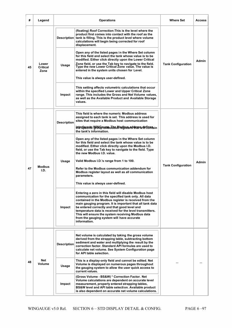
7/16/2019 3900 Manual
http://slidepdf.com/reader/full/3900-manual 145/266
WINGAUGE v5.0 Rel. SECTION 6 – STD DISPLAY DETAIL & CONFIG. PAGE 6 –97
# Legend Operations Where Set Access
45 Lower CriticalZone
Description
(floating) Roof Correction:This is the level where theproduct first comes into contact with the roof as thetank is filling. This is the product level where volumecalculations will begin being corrected for roof displacement.
Usage
Open any of the listed pages in the Where Set columnfor this field and select the tank whose value is to bemodified. Either click directly upon the Lower Critical
Zone field, or use the Tab key to navigate to the field.Type the new Lower Critical Zone value. The value isentered in the system units chosen for Level.
This value is always user-defined.
Impact
This setting affects volumetric calculations that occur within the specified Lower and Upper Critical Zonerange. This includes the Gross and Net Volume values,as well as the Available Product and Available Storagevalues.
Tank Configuration Admin
47 ModbusI.D.
Description
This field is where the numeric Modbus addressassigned to each tank is set. This address is used for sites that require a Modbus host communication
interface to WINGauge. The Modbus address definesthe specific group of Modbus registers that will containthe tank's information.
Usage
Open any of the listed pages in the Where Set columnfor this field and select the tank whose value is to bemodified. Either click directly upon the Modbus I.D.field, or use the Tab key to navigate to the field. Typethe new Modbus I.D. value.
Valid Modbus I.D.'s range from 1 to 100.
Refer to the Modbus communication addendum for Modbus register layout as well as all communicationparameters.
This value is always user-defined.
Impact
Entering a zero in this field will disable Modbus hostcommunication for the specified tank only. All datacontained in the Modbus register is received from themain gauging program. It is important that all tank databe entered correctly and that good level andtemperature data is received for the level transmitters.This will ensure the system receiving Modbus datafrom the gauging system will have accurateinformation.
Tank Configuration Admin
48 NetVolume
Description
Net volume is calculated by taking the gross volumederived from the strapping table, subtracting bottomsediment and water and multiplying the result by thecorrection factor. Standard API formulas are used tocalculate net volume. See System Configuration page
for API table selection.
Usage This is a display-only field and cannot be edited. NetVolume is displayed on numerous pages throughoutthe gauging system to allow the user quick access tocurrent values.
Impact
(Gross Volume - BS&W) * Correction Factor. NetVolume calculations are dependent on accurate levelmeasurement, properly entered strapping tables,BS&W level and API table selection. Available productis also dependent on accurate net volume calculations.
... ...
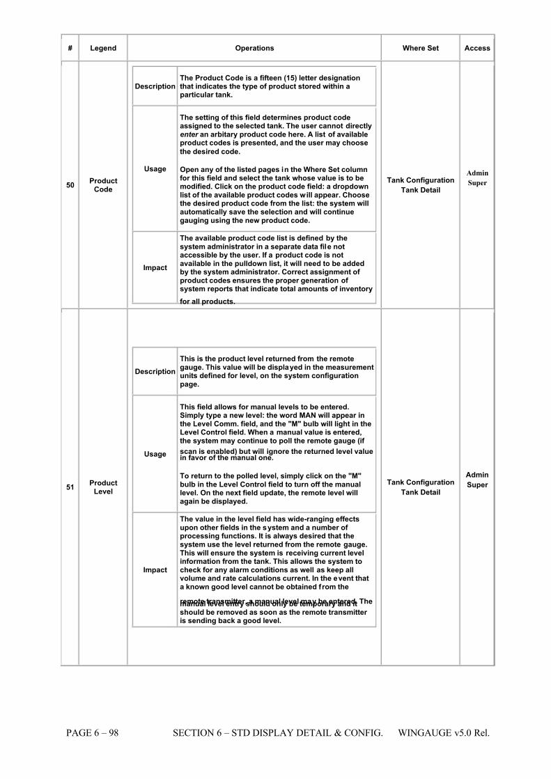
7/16/2019 3900 Manual
http://slidepdf.com/reader/full/3900-manual 146/266
PAGE 6 – 98 SECTION 6 – STD DISPLAY DETAIL & CONFIG. WINGAUGE v5.0 Rel.
# Legend Operations Where Set Access
50 ProductCode
Description The Product Code is a fifteen (15) letter designationthat indicates the type of product stored within aparticular tank.
Usage
The setting of this field determines product codeassigned to the selected tank. The user cannot directlyenter an arbitary product code here. A list of availableproduct codes is presented, and the user may choose
the desired code.
Open any of the listed pages in the Where Set columnfor this field and select the tank whose value is to bemodified. Click on the product code field: a dropdownlist of the available product codes will appear. Choosethe desired product code from the list: the system willautomatically save the selection and will continuegauging using the new product code.
Impact
The available product code list is defined by thesystem administrator in a separate data file notaccessible by the user. If a product code is notavailable in the pulldown list, it will need to be addedby the system administrator. Correct assignment of product codes ensures the proper generation of system reports that indicate total amounts of inventory
for all products.
Tank Configuration Tank Detail
Admin
Super
51 ProductLevel
Description This is the product level returned from the remotegauge. This value will be displayed in the measurementunits defined for level, on the system configurationpage.
Usage
This field allows for manual levels to be entered.Simply type a new level: the word MAN will appear inthe Level Comm. field, and the "M" bulb will light in theLevel Control field. When a manual value is entered,the system may continue to poll the remote gauge (if
scan is enabled) but will ignore the returned level valuein favor of the manual one.
To return to the polled level, simply click on the "M"bulb in the Level Control field to turn off the manuallevel. On the next field update, the remote level willagain be displayed.
Impact
The value in the level field has wide-ranging effectsupon other fields in the system and a number of processing functions. It is always desired that thesystem use the level returned from the remote gauge.This will ensure the system is receiving current levelinformation from the tank. This allows the system tocheck for any alarm conditions as well as keep allvolume and rate calculations current. In the event thata known good level cannot be obtained from the
remote transmitter, a manual level may be entered. Themanual level entry should only be temporary and itshould be removed as soon as the remote transmitter is sending back a good level.
Tank Configuration Tank Detail
Admin
Super
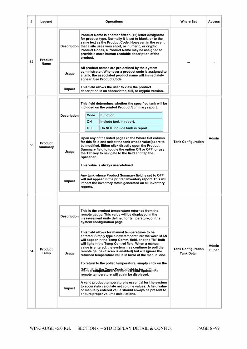
7/16/2019 3900 Manual
http://slidepdf.com/reader/full/3900-manual 147/266
WINGAUGE v5.0 Rel. SECTION 6 – STD DISPLAY DETAIL & CONFIG. PAGE 6 –99
# Legend Operations Where Set Access
52 ProductName
Description
Product Name is another fifteen (15) letter designator for product type. Normally it is set to blank, or to thesame text as the Product Code. However, in the eventthat a site uses very short, or numeric, or crypticProduct Codes, a Product Name may be assigned toprovide a more human-readable description of theproduct.
Usage All product names are pre-defined by the systemadministrator. Whenever a product code is assigned toa tank, the associated product name will immediatelyappear. See Product Code.
Impact This field allows the user to view the productdescription in an abbreviated, full, or cryptic version.
... ...
53 ProductSummary
Description
This field determines whether the specified tank will beincluded on the printed Product Summary report.
Code Function
ON Include tank in report.
OFF Do NOT include tank in report.
Usage
Open any of the listed pages in the Where Set columnfor this field and select the tank whose value(s) are tobe modified. Either click directly upon the ProductSummary field to toggle the option ON or OFF, or usethe Tab key to navigate to the field and tap theSpacebar.
This value is always user-defined.
Impact Any tank whose Product Summary field is set to OFFwill not appear in the printed Inventory report. This willimpact the inventory totals generated on all inventoryreports.
Tank Configuration Admin
54 ProductTemp
Description This is the product temperature returned from theremote gauge. This value will be displayed in themeasurement units defined for temperature, on thesystem configuration page.
Usage
This field allows for manual temperatures to beentered. Simply type a new temperature: the word MANwill appear in the Temp Comm. field, and the "M" bulbwill light in the Temp Control field. When a manualvalue is entered, the system may continue to poll theremote gauge (if scan is enabled) but will ignore thereturned temperature value in favor of the manual one.
To return to the polled temperature, simply click on the
"M" bulb in the Temp Control field to turn off themanual temperature. On the next field update, theremote temperature will again be displayed.
Impact A valid product temperature is essential for the systemto accurately calculate net volume values. A field valueor manually entered value should always be present toensure proper volume calculations.
Tank Configuration Tank Detail
Admin
Super
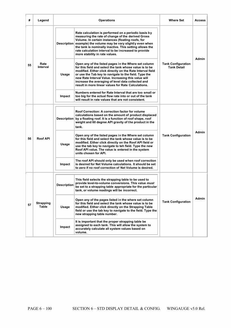
7/16/2019 3900 Manual
http://slidepdf.com/reader/full/3900-manual 148/266
PAGE 6 – 100 SECTION 6 – STD DISPLAY DETAIL & CONFIG. WINGAUGE v5.0 Rel.
# Legend Operations Where Set Access
55 RateInterval
Description
Rate calculation is performed on a periodic basis bymeasuring the rate of change of the derived GrossVolume. In certain instances (floating roofs, for example) the volume may be vary slightly even whenthe tank is nominally inactive. This setting allows therate calculation interval to be increased to providemore stability in rate values.
Usage
Open any of the listed pages in the Where set columnfor this field and select the tank whose value is to bemodified. Either click directly on the Rate Interval fieldor use the Tab key to navigate to the field. Type thenew Rate Interval Value. Increasing this value willincrease the averaging of level data collected andresult in more linear values for Rate Calculations.
Impact Numbers entered for Rate Interval that are too small or too big for the actual flow rate into or out of the tankwill result in rate values that are not consistent.
Tank Configuration Tank Detail
Admin
56 Roof API
Description
Roof Correction: A correction factor for volumecalculations based on the amount of product displacedby a floating roof. It is a function of roof shape, roof weight and 60 degree API gravity of the product in the
tank.
Usage
Open any of the listed pages in the Where set columnfor this field and select the tank whose value is to bemodified. Either click directly on the Roof API field or use the tab key to navigate to teh field. Type the newRoof API value. The value is entered in the systemunits chosen for API.
Impact The roof API should only be used when roof correctionis desired for Net Volume calculations. It should be setto zero if no roof correction of Net Volume is desired.
Tank Configuration Admin
57 StrappingTable
Description This field selects the strapping table to be used toprovide level-to-volume conversions. This value must be set to a strapping table appropriate for the particular tank, or volume readings will be incorrect.
Usage
Open any of the pages listed in the where set columnfor this field and select the tank whose value is to bemodified. Either click directly on the Strapping Tablefield or use the tab key to navigate to the field. Type thenew strapping table number.
Impact It is important that the proper strapping table beassigned to each tank. This will allow the system toaccurately calculate all system values based onvolume.
Tank Configuration Admin
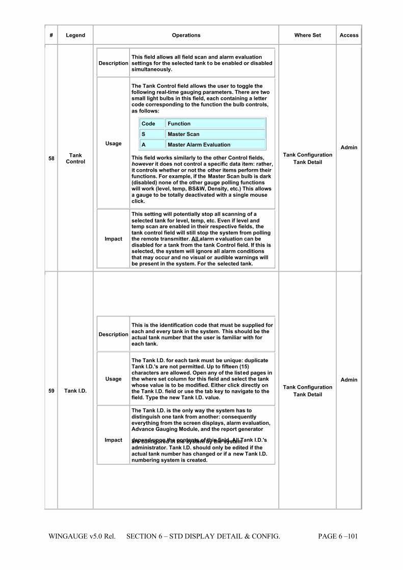
7/16/2019 3900 Manual
http://slidepdf.com/reader/full/3900-manual 149/266
WINGAUGE v5.0 Rel. SECTION 6 – STD DISPLAY DETAIL & CONFIG. PAGE 6 –101
# Legend Operations Where Set Access
58 TankControl
Description This field allows all field scan and alarm evaluationsettings for the selected tank to be enabled or disabledsimultaneously.
Usage
The Tank Control field allows the user to toggle thefollowing real-time gauging parameters. There are twosmall light bulbs in this field, each containing a letter code corresponding to the function the bulb controls,
as follows:
Code Function
S Master Scan
A Master Alarm Evaluation
This field works similarly to the other Control fields,however it does not control a specific data item: rather,it controls whether or not the other items perform their functions. For example, if the Master Scan bulb is dark(disabled) none of the other gauge polling functionswill work (level, temp, BS&W, Density, etc.) This allowsa gauge to be totally deactivated with a single mouseclick.
Impact
This setting will potentially stop all scanning of a
selected tank for level, temp, etc. Even if level andtemp scan are enabled in their respective fields, thetank control field will still stop the system from pollingthe remote transmitter. All alarm evaluation can bedisabled for a tank from the tank Control field. If this isselected, the system will ignore all alarm conditionsthat may occur and no visual or audible warnings willbe present in the system. For the selected tank.
Tank Configuration Tank Detail
Admin
59 Tank I.D.
Description This is the identification code that must be supplied for each and every tank in the system. This should be theactual tank number that the user is familiar with for each tank.
Usage
The Tank I.D. for each tank must be unique: duplicateTank I.D.'s are not permitted. Up to fifteen (15)characters are allowed. Open any of the listed pages inthe where set column for this field and select the tankwhose value is to be modified. Either click directly onthe Tank I.D. field or use the tab key to navigate to thefield. Type the new Tank I.D. value.
Impact
The Tank I.D. is the only way the system has todistinguish one tank from another: consequentlyeverything from the screen displays, alarm evaluation,Advance Gauging Module, and the report generator
depend upon the contents of this field. All Tank I.D.'sare configured in the system by the systemadministrator. Tank I.D. should only be edited if theactual tank number has changed or if a new Tank I.D.numbering system is created.
Tank Configuration Tank Detail
Admin
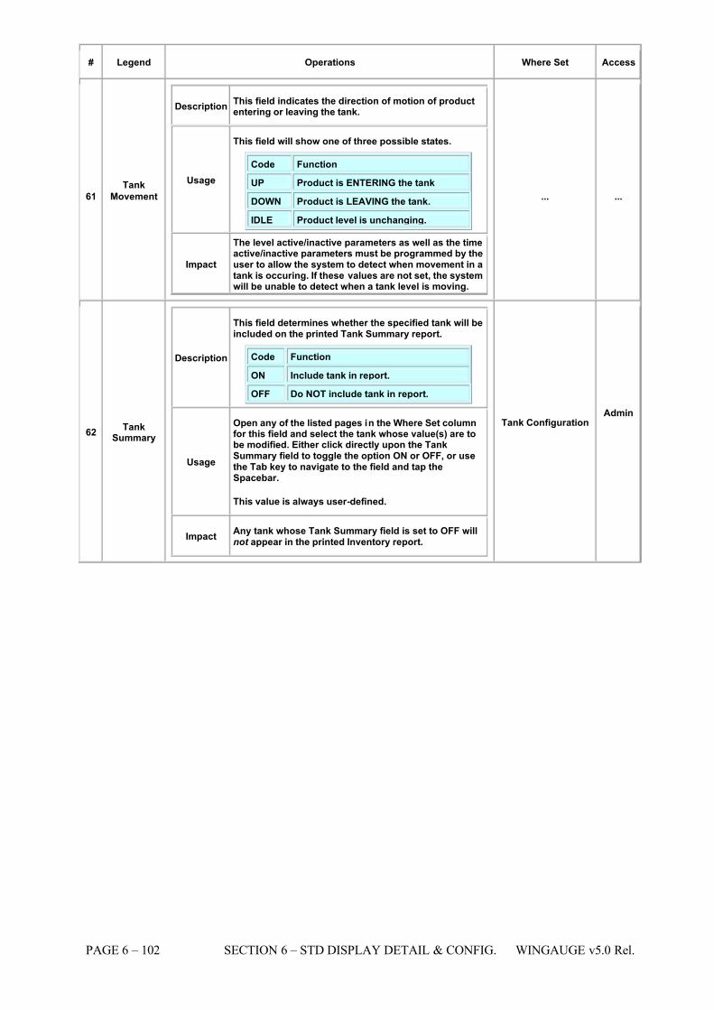
7/16/2019 3900 Manual
http://slidepdf.com/reader/full/3900-manual 150/266
PAGE 6 – 102 SECTION 6 – STD DISPLAY DETAIL & CONFIG. WINGAUGE v5.0 Rel.
# Legend Operations Where Set Access
61 Tank
Movement
Description This field indicates the direction of motion of productentering or leaving the tank.
Usage
This field will show one of three possible states.
Code Function
UP Product is ENTERING the tank
DOWN Product is LEAVING the tank.
IDLE Product level is unchanging.
Impact
The level active/inactive parameters as well as the timeactive/inactive parameters must be programmed by theuser to allow the system to detect when movement in atank is occuring. If these values are not set, the systemwill be unable to detect when a tank level is moving.
... ...
62 TankSummary
Description
This field determines whether the specified tank will beincluded on the printed Tank Summary report.
Code Function
ON Include tank in report.
OFF Do NOT include tank in report.
Usage
Open any of the listed pages in the Where Set columnfor this field and select the tank whose value(s) are tobe modified. Either click directly upon the TankSummary field to toggle the option ON or OFF, or usethe Tab key to navigate to the field and tap theSpacebar.
This value is always user-defined.
Impact Any tank whose Tank Summary field is set to OFF willnot appear in the printed Inventory report.
Tank Configuration Admin
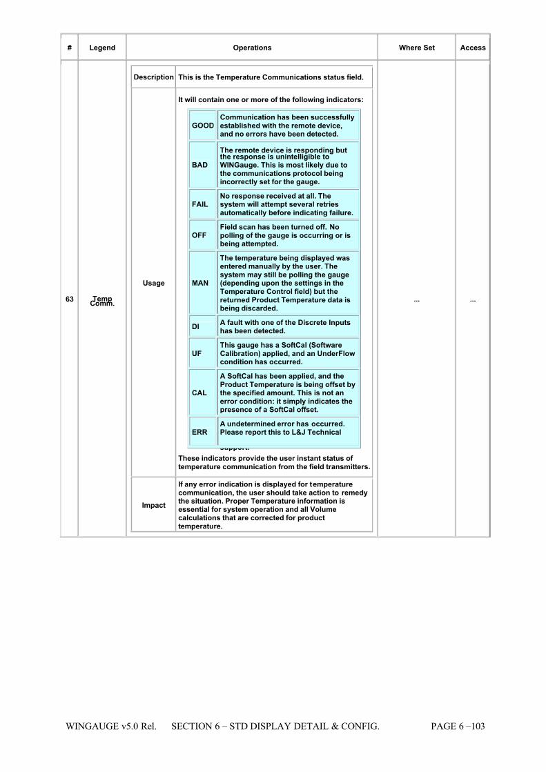
7/16/2019 3900 Manual
http://slidepdf.com/reader/full/3900-manual 151/266
WINGAUGE v5.0 Rel. SECTION 6 – STD DISPLAY DETAIL & CONFIG. PAGE 6 –103
# Legend Operations Where Set Access
63 TempComm.
Description This is the Temperature Communications status field.
Usage
It will contain one or more of the following indicators:
GOOD Communication has been successfullyestablished with the remote device,and no errors have been detected.
BAD
The remote device is responding butthe response is unintelligible toWINGauge. This is most likely due tothe communications protocol beingincorrectly set for the gauge.
FAIL No response received at all. Thesystem will attempt several retriesautomatically before indicating failure.
OFF Field scan has been turned off. Nopolling of the gauge is occurring or isbeing attempted.
MAN
The temperature being displayed wasentered manually by the user. Thesystem may still be polling the gauge(depending upon the settings in theTemperature Control field) but thereturned Product Temperature data isbeing discarded.
DI A fault with one of the Discrete Inputshas been detected.
UF This gauge has a SoftCal (SoftwareCalibration) applied, and an UnderFlowcondition has occurred.
CAL
A SoftCal has been applied, and theProduct Temperature is being offset bythe specified amount. This is not anerror condition: it simply indicates thepresence of a SoftCal offset.
ERR A undetermined error has occurred.Please report this to L&J Technical
support. These indicators provide the user instant status of temperature communication from the field transmitters.
Impact
If any error indication is displayed for temperaturecommunication, the user should take action to remedythe situation. Proper Temperature information isessential for system operation and all Volumecalculations that are corrected for producttemperature.
... ...
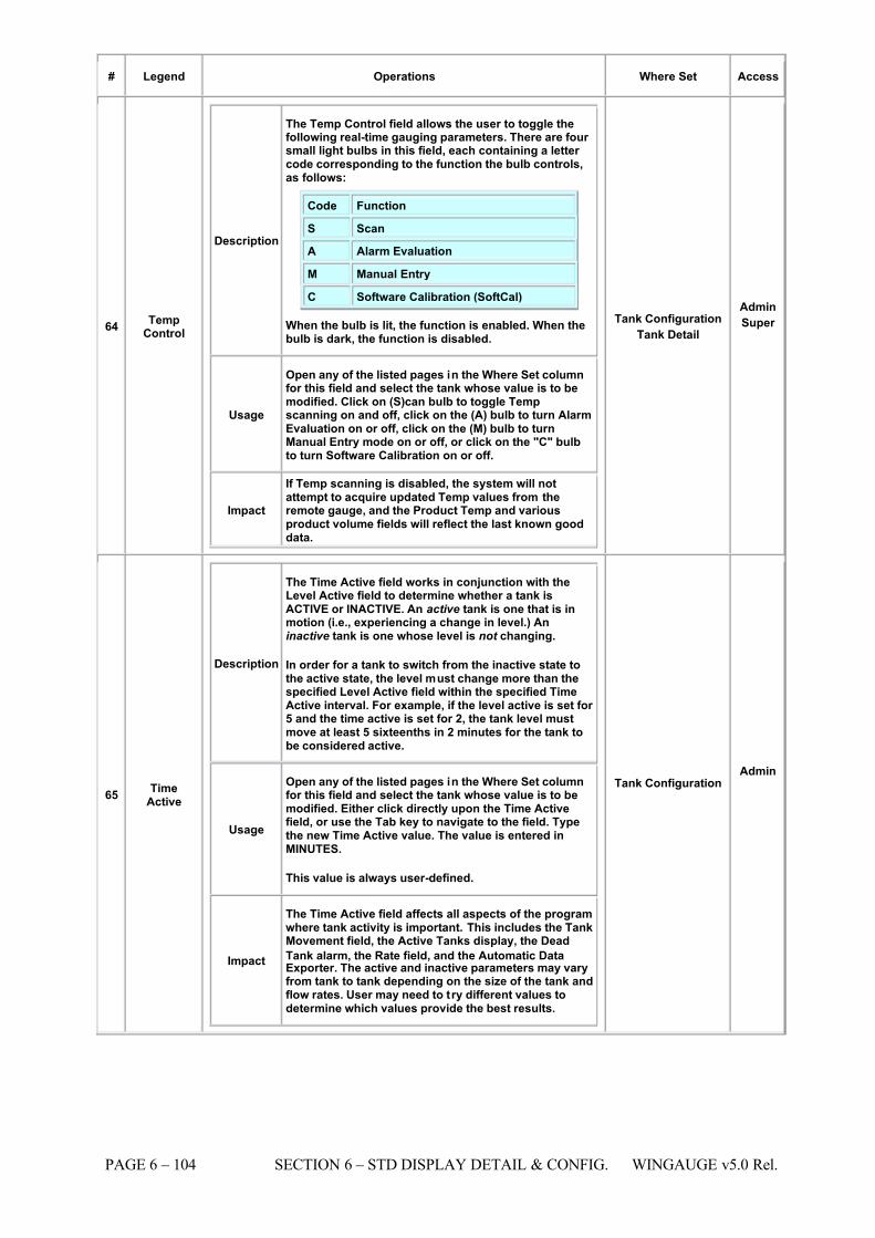
7/16/2019 3900 Manual
http://slidepdf.com/reader/full/3900-manual 152/266
PAGE 6 – 104 SECTION 6 – STD DISPLAY DETAIL & CONFIG. WINGAUGE v5.0 Rel.
# Legend Operations Where Set Access
64 TempControl
Description
The Temp Control field allows the user to toggle thefollowing real-time gauging parameters. There are four small light bulbs in this field, each containing a letter code corresponding to the function the bulb controls,as follows:
Code Function
S
Scan
A Alarm Evaluation
M Manual Entry
C Software Calibration (SoftCal)
When the bulb is lit, the function is enabled. When thebulb is dark, the function is disabled.
Usage
Open any of the listed pages in the Where Set columnfor this field and select the tank whose value is to bemodified. Click on (S)can bulb to toggle Tempscanning on and off, click on the (A) bulb to turn AlarmEvaluation on or off, click on the (M) bulb to turnManual Entry mode on or off, or click on the "C" bulbto turn Software Calibration on or off.
Impact
If Temp scanning is disabled, the system will notattempt to acquire updated Temp values from theremote gauge, and the Product Temp and variousproduct volume fields will reflect the last known gooddata.
Tank Configuration Tank Detail
Admin
Super
65 TimeActive
Description
The Time Active field works in conjunction with theLevel Active field to determine whether a tank isACTIVE or INACTIVE. An active tank is one that is inmotion (i.e., experiencing a change in level.) Aninactive tank is one whose level is not changing.
In order for a tank to switch from the inactive state tothe active state, the level must change more than thespecified Level Active field within the specified TimeActive interval. For example, if the level active is set for 5 and the time active is set for 2, the tank level mustmove at least 5 sixteenths in 2 minutes for the tank tobe considered active.
Usage
Open any of the listed pages in the Where Set columnfor this field and select the tank whose value is to bemodified. Either click directly upon the Time Activefield, or use the Tab key to navigate to the field. Typethe new Time Active value. The value is entered inMINUTES.
This value is always user-defined.
Impact
The Time Active field affects all aspects of the programwhere tank activity is important. This includes the TankMovement field, the Active Tanks display, the Dead
Tank alarm, the Rate field, and the Automatic DataExporter. The active and inactive parameters may varyfrom tank to tank depending on the size of the tank andflow rates. User may need to try different values todetermine which values provide the best results.
Tank Configuration Admin
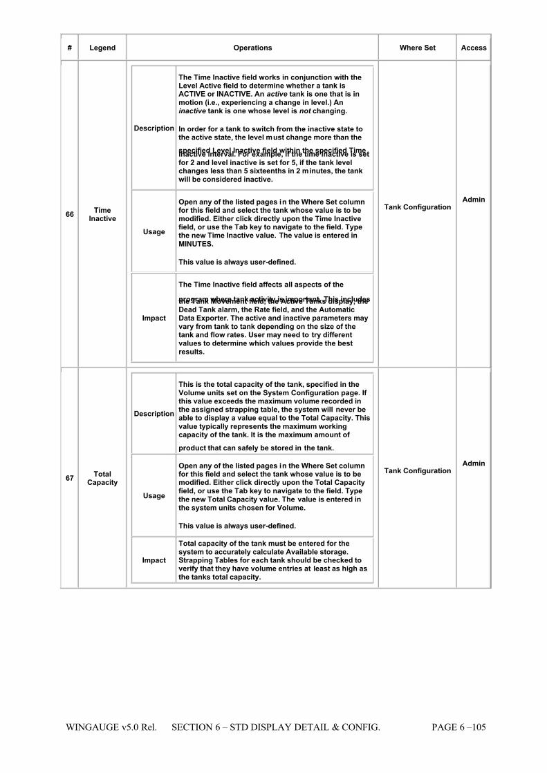
7/16/2019 3900 Manual
http://slidepdf.com/reader/full/3900-manual 153/266
WINGAUGE v5.0 Rel. SECTION 6 – STD DISPLAY DETAIL & CONFIG. PAGE 6 –105
# Legend Operations Where Set Access
66 TimeInactive
Description
The Time Inactive field works in conjunction with theLevel Active field to determine whether a tank isACTIVE or INACTIVE. An active tank is one that is inmotion (i.e., experiencing a change in level.) Aninactive tank is one whose level is not changing.
In order for a tank to switch from the inactive state tothe active state, the level must change more than the
specified Level Inactive field within the specified TimeInactive interval. For example, if the time inactive is setfor 2 and level inactive is set for 5, if the tank levelchanges less than 5 sixteenths in 2 minutes, the tankwill be considered inactive.
Usage
Open any of the listed pages in the Where Set columnfor this field and select the tank whose value is to bemodified. Either click directly upon the Time Inactivefield, or use the Tab key to navigate to the field. Typethe new Time Inactive value. The value is entered in
MINUTES.
This value is always user-defined.
Impact
The Time Inactive field affects all aspects of the
program where tank activity is important. This includesthe Tank Movement field, the Active Tanks display, theDead Tank alarm, the Rate field, and the AutomaticData Exporter. The active and inactive parameters mayvary from tank to tank depending on the size of thetank and flow rates. User may need to try differentvalues to determine which values provide the bestresults.
Tank Configuration Admin
67 TotalCapacity
Description
This is the total capacity of the tank, specified in theVolume units set on the System Configuration page. If this value exceeds the maximum volume recorded inthe assigned strapping table, the system will never beable to display a value equal to the Total Capacity. Thisvalue typically represents the maximum workingcapacity of the tank. It is the maximum amount of
product that can safely be stored in the tank.
Usage
Open any of the listed pages in the Where Set columnfor this field and select the tank whose value is to bemodified. Either click directly upon the Total Capacityfield, or use the Tab key to navigate to the field. Typethe new Total Capacity value. The value is entered inthe system units chosen for Volume.
This value is always user-defined.
Impact
Total capacity of the tank must be entered for thesystem to accurately calculate Available storage.Strapping Tables for each tank should be checked toverify that they have volume entries at least as high asthe tanks total capacity.
Tank Configuration Admin
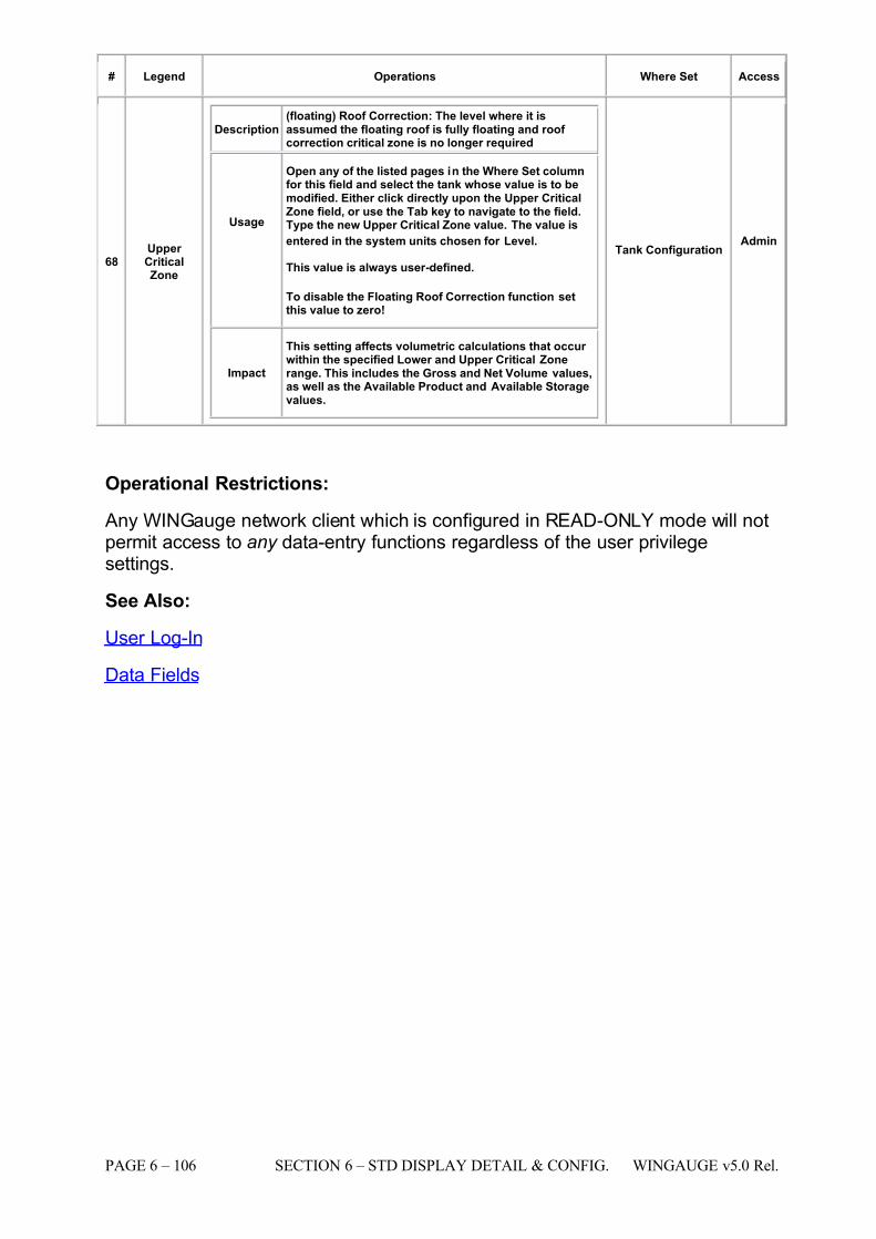
7/16/2019 3900 Manual
http://slidepdf.com/reader/full/3900-manual 154/266
PAGE 6 – 106 SECTION 6 – STD DISPLAY DETAIL & CONFIG. WINGAUGE v5.0 Rel.
# Legend Operations Where Set Access
68 Upper CriticalZone
Description (floating) Roof Correction: The level where it isassumed the floating roof is fully floating and roof correction critical zone is no longer required
Usage
Open any of the listed pages in the Where Set columnfor this field and select the tank whose value is to bemodified. Either click directly upon the Upper CriticalZone field, or use the Tab key to navigate to the field.Type the new Upper Critical Zone value. The value is
entered in the system units chosen for Level.
This value is always user-defined.
To disable the Floating Roof Correction function setthis value to zero!
Impact
This setting affects volumetric calculations that occur within the specified Lower and Upper Critical Zonerange. This includes the Gross and Net Volume values,as well as the Available Product and Available Storagevalues.
Tank Configuration Admin
Operational Restrictions:
Any WINGauge network client which is configured in READ-ONLY mode will notpermit access to any data-entry functions regardless of the user privilegesettings.
See Also:
User Log-In
Data Fields
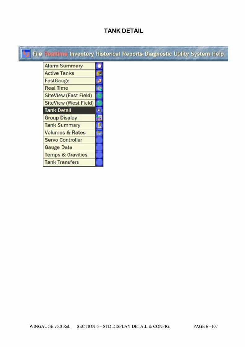
7/16/2019 3900 Manual
http://slidepdf.com/reader/full/3900-manual 155/266
WINGAUGE v5.0 Rel. SECTION 6 – STD DISPLAY DETAIL & CONFIG. PAGE 6 –107
TANK DETAIL
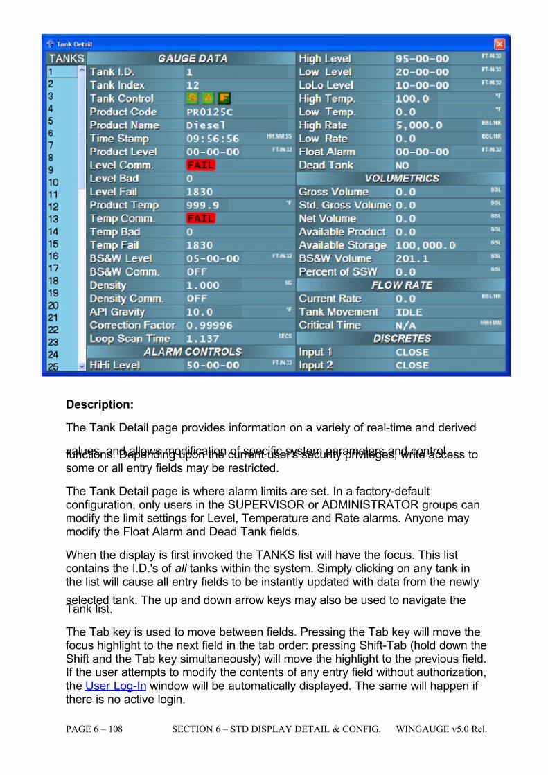
7/16/2019 3900 Manual
http://slidepdf.com/reader/full/3900-manual 156/266
PAGE 6 – 108 SECTION 6 – STD DISPLAY DETAIL & CONFIG. WINGAUGE v5.0 Rel.
Description:
The Tank Detail page provides information on a variety of real-time and derived
values, and allows modification of specific system parameters and controlfunctions. Depending upon the current user's security privileges, write access tosome or all entry fields may be restricted.
The Tank Detail page is where alarm limits are set. In a factory-defaultconfiguration, only users in the SUPERVISOR or ADMINISTRATOR groups canmodify the limit settings for Level, Temperature and Rate alarms. Anyone maymodify the Float Alarm and Dead Tank fields.
When the display is first invoked the TANKS list will have the focus. This listcontains the I.D.'s of all tanks within the system. Simply clicking on any tank inthe list will cause all entry fields to be instantly updated with data from the newly
selected tank. The up and down arrow keys may also be used to navigate theTank list.
The Tab key is used to move between fields. Pressing the Tab key will move thefocus highlight to the next field in the tab order: pressing Shift-Tab (hold down theShift and the Tab key simultaneously) will move the highlight to the previous field. If the user attempts to modify the contents of any entry field without authorization,the User Log-In window will be automatically displayed. The same will happen if there is no active login.
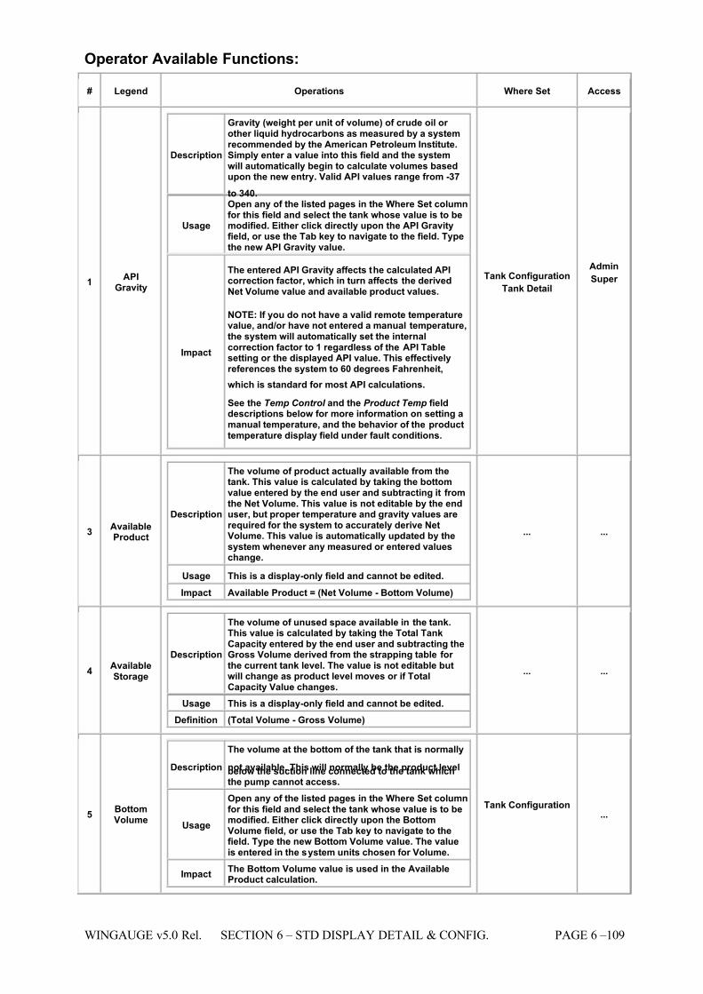
7/16/2019 3900 Manual
http://slidepdf.com/reader/full/3900-manual 157/266
WINGAUGE v5.0 Rel. SECTION 6 – STD DISPLAY DETAIL & CONFIG. PAGE 6 –109
Operator Available Functions:
# Legend Operations Where Set Access
1 APIGravity
Description
Gravity (weight per unit of volume) of crude oil or other liquid hydrocarbons as measured by a systemrecommended by the American Petroleum Institute.Simply enter a value into this field and the systemwill automatically begin to calculate volumes basedupon the new entry. Valid API values range from -37
to 340.
Usage
Open any of the listed pages in the Where Set columnfor this field and select the tank whose value is to bemodified. Either click directly upon the API Gravityfield, or use the Tab key to navigate to the field. Typethe new API Gravity value.
Impact
The entered API Gravity affects the calculated APIcorrection factor, which in turn affects the derivedNet Volume value and available product values.
NOTE: If you do not have a valid remote temperaturevalue, and/or have not entered a manual temperature,the system will automatically set the internalcorrection factor to 1 regardless of the API Tablesetting or the displayed API value. This effectivelyreferences the system to 60 degrees Fahrenheit,
which is standard for most API calculations.
See the Temp Control and the Product Temp fielddescriptions below for more information on setting amanual temperature, and the behavior of the producttemperature display field under fault conditions.
Tank Configuration Tank Detail
Admin
Super
3 AvailableProduct
Description
The volume of product actually available from thetank. This value is calculated by taking the bottomvalue entered by the end user and subtracting it fromthe Net Volume. This value is not editable by the enduser, but proper temperature and gravity values arerequired for the system to accurately derive NetVolume. This value is automatically updated by thesystem whenever any measured or entered valueschange.
Usage This is a display-only field and cannot be edited. Impact Available Product = (Net Volume - Bottom Volume)
... ...
4 AvailableStorage
Description
The volume of unused space available in the tank.This value is calculated by taking the Total TankCapacity entered by the end user and subtracting theGross Volume derived from the strapping table for the current tank level. The value is not editable butwill change as product level moves or if TotalCapacity Value changes.
Usage This is a display-only field and cannot be edited. Definition (Total Volume - Gross Volume)
... ...
5 BottomVolume
Description
The volume at the bottom of the tank that is normally
not available. This will normally be the product levelbelow the suction line connected to the tank whichthe pump cannot access.
Usage
Open any of the listed pages in the Where Set columnfor this field and select the tank whose value is to bemodified. Either click directly upon the BottomVolume field, or use the Tab key to navigate to thefield. Type the new Bottom Volume value. The valueis entered in the system units chosen for Volume.
Impact The Bottom Volume value is used in the AvailableProduct calculation.
Tank Configuration ...
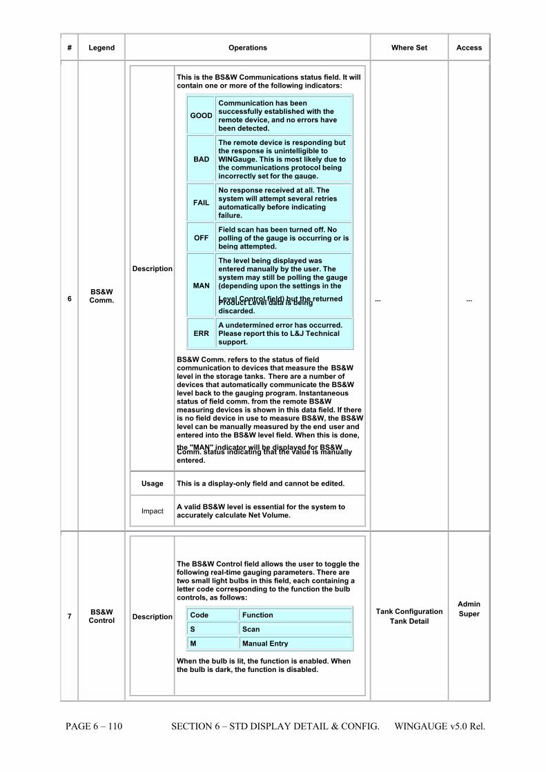
7/16/2019 3900 Manual
http://slidepdf.com/reader/full/3900-manual 158/266
PAGE 6 – 110 SECTION 6 – STD DISPLAY DETAIL & CONFIG. WINGAUGE v5.0 Rel.
# Legend Operations Where Set Access
6 BS&WComm.
Description
This is the BS&W Communications status field. It willcontain one or more of the following indicators:
GOOD Communication has beensuccessfully established with theremote device, and no errors havebeen detected.
BAD
The remote device is responding butthe response is unintelligible toWINGauge. This is most likely due tothe communications protocol beingincorrectly set for the gauge.
FAIL No response received at all. Thesystem will attempt several retriesautomatically before indicatingfailure.
OFF Field scan has been turned off. Nopolling of the gauge is occurring or isbeing attempted.
MAN
The level being displayed wasentered manually by the user. Thesystem may still be polling the gauge(depending upon the settings in the
Level Control field) but the returnedProduct Level data is beingdiscarded.
ERR A undetermined error has occurred.Please report this to L&J Technicalsupport.
BS&W Comm. refers to the status of fieldcommunication to devices that measure the BS&Wlevel in the storage tanks. There are a number of devices that automatically communicate the BS&Wlevel back to the gauging program. Instantaneousstatus of field comm. from the remote BS&Wmeasuring devices is shown in this data field. If thereis no field device in use to measure BS&W, the BS&Wlevel can be manually measured by the end user andentered into the BS&W level field. When this is done,
the "MAN" indicator will be displayed for BS&WComm. status indicating that the value is manuallyentered.
Usage This is a display-only field and cannot be edited.
ImpactA valid BS&W level is essential for the system toaccurately calculate Net Volume.
... ...
7 BS&WControl Description
The BS&W Control field allows the user to toggle thefollowing real-time gauging parameters. There aretwo small light bulbs in this field, each containing aletter code corresponding to the function the bulbcontrols, as follows:
Code Function
S Scan
M Manual Entry
When the bulb is lit, the function is enabled. Whenthe bulb is dark, the function is disabled.
Tank Configuration Tank Detail
Admin
Super
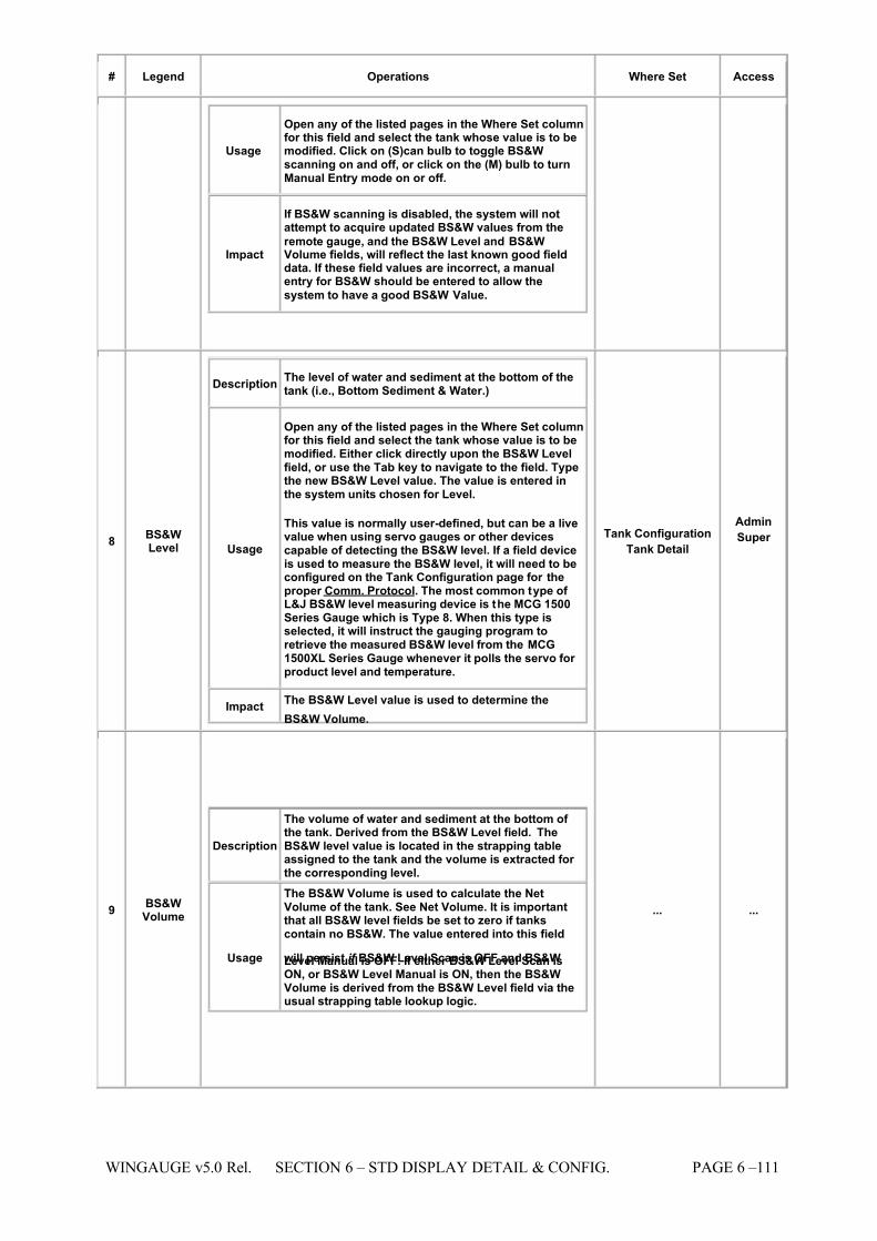
7/16/2019 3900 Manual
http://slidepdf.com/reader/full/3900-manual 159/266
WINGAUGE v5.0 Rel. SECTION 6 – STD DISPLAY DETAIL & CONFIG. PAGE 6 –111
# Legend Operations Where Set Access
Usage
Open any of the listed pages in the Where Set columnfor this field and select the tank whose value is to bemodified. Click on (S)can bulb to toggle BS&Wscanning on and off, or click on the (M) bulb to turnManual Entry mode on or off.
Impact
If BS&W scanning is disabled, the system will notattempt to acquire updated BS&W values from the
remote gauge, and the BS&W Level and BS&WVolume fields, will reflect the last known good fielddata. If these field values are incorrect, a manualentry for BS&W should be entered to allow the
system to have a good BS&W Value.
8 BS&WLevel
Description The level of water and sediment at the bottom of thetank (i.e., Bottom Sediment & Water.)
Usage
Open any of the listed pages in the Where Set columnfor this field and select the tank whose value is to bemodified. Either click directly upon the BS&W Levelfield, or use the Tab key to navigate to the field. Typethe new BS&W Level value. The value is entered inthe system units chosen for Level.
This value is normally user-defined, but can be a livevalue when using servo gauges or other devicescapable of detecting the BS&W level. If a field deviceis used to measure the BS&W level, it will need to beconfigured on the Tank Configuration page for theproper Comm. Protocol. The most common type of L&J BS&W level measuring device is the MCG 1500Series Gauge which is Type 8. When this type isselected, it will instruct the gauging program toretrieve the measured BS&W level from the MCG1500XL Series Gauge whenever it polls the servo for product level and temperature.
Impact
The BS&W Level value is used to determine the
BS&W Volume.
Tank Configuration Tank Detail
Admin
Super
9 BS&WVolume
Description
The volume of water and sediment at the bottom of the tank. Derived from the BS&W Level field. TheBS&W level value is located in the strapping tableassigned to the tank and the volume is extracted for the corresponding level.
Usage
The BS&W Volume is used to calculate the NetVolume of the tank. See Net Volume. It is importantthat all BS&W level fields be set to zero if tankscontain no BS&W. The value entered into this field
will persist if BS&W Level Scan is OFF and BS&WLevel Manual is OFF. If either BS&W Level Scan isON, or BS&W Level Manual is ON, then the BS&WVolume is derived from the BS&W Level field via theusual strapping table lookup logic.
... ...
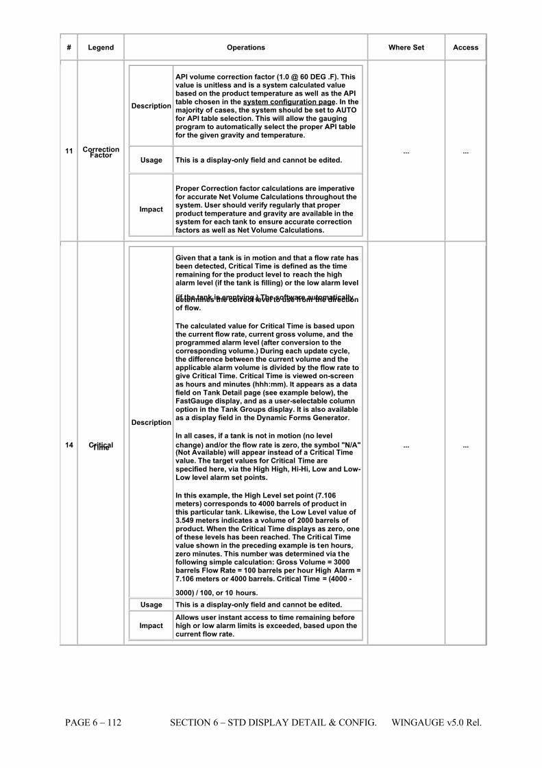
7/16/2019 3900 Manual
http://slidepdf.com/reader/full/3900-manual 160/266
PAGE 6 – 112 SECTION 6 – STD DISPLAY DETAIL & CONFIG. WINGAUGE v5.0 Rel.
# Legend Operations Where Set Access
11 CorrectionFactor
Description
API volume correction factor (1.0 @ 60 DEG .F). Thisvalue is unitless and is a system calculated valuebased on the product temperature as well as the APItable chosen in the system configuration page. In themajority of cases, the system should be set to AUTOfor API table selection. This will allow the gaugingprogram to automatically select the proper API tablefor the given gravity and temperature.
Usage This is a display-only field and cannot be edited.
Impact
Proper Correction factor calculations are imperativefor accurate Net Volume Calculations throughout thesystem. User should verify regularly that proper product temperature and gravity are available in thesystem for each tank to ensure accurate correctionfactors as well as Net Volume Calculations.
... ...
14 CriticalTime
Description
Given that a tank is in motion and that a flow rate hasbeen detected, Critical Time is defined as the timeremaining for the product level to reach the highalarm level (if the tank is filling) or the low alarm level
(if the tank is emptying.) The software automaticallydetermines the correct level to use from the directionof flow.
The calculated value for Critical Time is based uponthe current flow rate, current gross volume, and theprogrammed alarm level (after conversion to thecorresponding volume.) During each update cycle,the difference between the current volume and theapplicable alarm volume is divided by the flow rate togive Critical Time. Critical Time is viewed on-screenas hours and minutes (hhh:mm). It appears as a datafield on Tank Detail page (see example below), theFastGauge display, and as a user-selectable columnoption in the Tank Groups display. It is also availableas a display field in the Dynamic Forms Generator.
In all cases, if a tank is not in motion (no level
change) and/or the flow rate is zero, the symbol "N/A"(Not Available) will appear instead of a Critical Timevalue. The target values for Critical Time arespecified here, via the High High, Hi-Hi, Low and Low-Low level alarm set points.
In this example, the High Level set point (7.106meters) corresponds to 4000 barrels of product inthis particular tank. Likewise, the Low Level value of 3.549 meters indicates a volume of 2000 barrels of product. When the Critical Time displays as zero, oneof these levels has been reached. The Critical Timevalue shown in the preceding example is ten hours,zero minutes. This number was determined via thefollowing simple calculation: Gross Volume = 3000barrels Flow Rate = 100 barrels per hour High Alarm =7.106 meters or 4000 barrels. Critical Time = (4000 -
3000) / 100, or 10 hours.
Usage This is a display-only field and cannot be edited.
Impact Allows user instant access to time remaining beforehigh or low alarm limits is exceeded, based upon thecurrent flow rate.
... ...
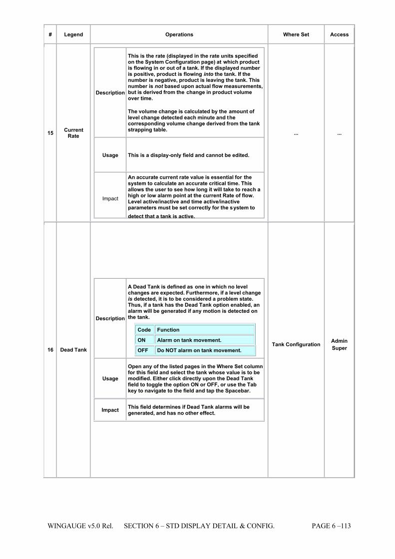
7/16/2019 3900 Manual
http://slidepdf.com/reader/full/3900-manual 161/266
WINGAUGE v5.0 Rel. SECTION 6 – STD DISPLAY DETAIL & CONFIG. PAGE 6 –113
# Legend Operations Where Set Access
15 CurrentRate
Description
This is the rate (displayed in the rate units specifiedon the System Configuration page) at which productis flowing in or out of a tank. If the displayed number is positive, product is flowing into the tank. If thenumber is negative, product is leaving the tank. Thisnumber is not based upon actual flow measurements,but is derived from the change in product volumeover time.
The volume change is calculated by the amount of level change detected each minute and thecorresponding volume change derived from the tankstrapping table.
Usage This is a display-only field and cannot be edited.
Impact
An accurate current rate value is essential for thesystem to calculate an accurate critical time. Thisallows the user to see how long it will take to reach ahigh or low alarm point at the current Rate of flow.Level active/inactive and time active/inactiveparameters must be set correctly for the system to
detect that a tank is active.
... ...
16 Dead Tank
Description
A Dead Tank is defined as one in which no levelchanges are expected. Furthermore, if a level changeis detected, it is to be considered a problem state.Thus, if a tank has the Dead Tank option enabled, analarm will be generated if any motion is detected onthe tank.
Code Function
ON Alarm on tank movement.
OFF Do NOT alarm on tank movement.
Usage
Open any of the listed pages in the Where Set columnfor this field and select the tank whose value is to bemodified. Either click directly upon the Dead Tankfield to toggle the option ON or OFF, or use the Tabkey to navigate to the field and tap the Spacebar.
Impact This field determines if Dead Tank alarms will begenerated, and has no other effect.
Tank Configuration Admin
Super
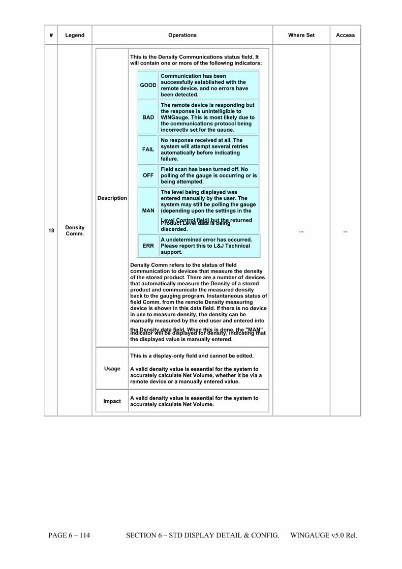
7/16/2019 3900 Manual
http://slidepdf.com/reader/full/3900-manual 162/266
PAGE 6 – 114 SECTION 6 – STD DISPLAY DETAIL & CONFIG. WINGAUGE v5.0 Rel.
# Legend Operations Where Set Access
18 DensityComm.
Description
This is the Density Communications status field. Itwill contain one or more of the following indicators:
GOOD Communication has beensuccessfully established with theremote device, and no errors havebeen detected.
BAD
The remote device is responding butthe response is unintelligible toWINGauge. This is most likely due tothe communications protocol beingincorrectly set for the gauge.
FAIL No response received at all. Thesystem will attempt several retriesautomatically before indicatingfailure.
OFF Field scan has been turned off. Nopolling of the gauge is occurring or isbeing attempted.
MAN
The level being displayed wasentered manually by the user. Thesystem may still be polling the gauge(depending upon the settings in the
Level Control field) but the returnedProduct Level data is beingdiscarded.
ERR A undetermined error has occurred.Please report this to L&J Technicalsupport.
Density Comm refers to the status of fieldcommunication to devices that measure the densityof the stored product. There are a number of devicesthat automatically measure the Density of a storedproduct and communicate the measured densityback to the gauging program. Instantaneous status of field Comm. from the remote Density measuringdevice is shown in this data field. If there is no devicein use to measure density, the density can bemanually measured by the end user and entered into
the Density data field. When this is done, the "MAN"indicator will be displayed for density, indicating thatthe displayed value is manually entered.
Usage
This is a display-only field and cannot be edited.
A valid density value is essential for the system toaccurately calculate Net Volume, whether it be via aremote device or a manually entered value.
Impact A valid density value is essential for the system toaccurately calculate Net Volume.
... ...
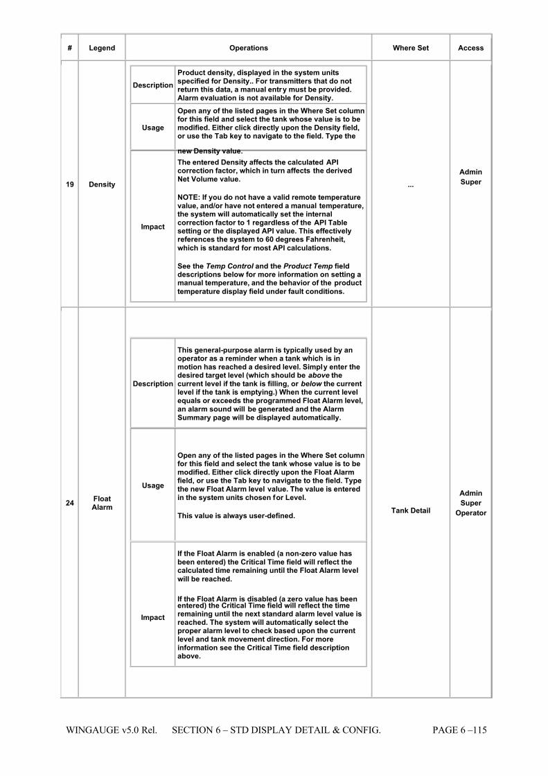
7/16/2019 3900 Manual
http://slidepdf.com/reader/full/3900-manual 163/266
WINGAUGE v5.0 Rel. SECTION 6 – STD DISPLAY DETAIL & CONFIG. PAGE 6 –115
# Legend Operations Where Set Access
19 Density
Description Product density, displayed in the system unitsspecified for Density.. For transmitters that do notreturn this data, a manual entry must be provided.Alarm evaluation is not available for Density.
Usage
Open any of the listed pages in the Where Set columnfor this field and select the tank whose value is to bemodified. Either click directly upon the Density field,or use the Tab key to navigate to the field. Type the
new Density value.
Impact
The entered Density affects the calculated APIcorrection factor, which in turn affects the derivedNet Volume value.
NOTE: If you do not have a valid remote temperaturevalue, and/or have not entered a manual temperature,the system will automatically set the internalcorrection factor to 1 regardless of the API Tablesetting or the displayed API value. This effectivelyreferences the system to 60 degrees Fahrenheit,
which is standard for most API calculations.
See the Temp Control and the Product Temp fielddescriptions below for more information on setting amanual temperature, and the behavior of the product
temperature display field under fault conditions.
... Admin
Super
24 FloatAlarm
Description
This general-purpose alarm is typically used by anoperator as a reminder when a tank which is inmotion has reached a desired level. Simply enter thedesired target level (which should be above thecurrent level if the tank is filling, or below the currentlevel if the tank is emptying.) When the current levelequals or exceeds the programmed Float Alarm level,an alarm sound will be generated and the AlarmSummary page will be displayed automatically.
Usage
Open any of the listed pages in the Where Set columnfor this field and select the tank whose value is to bemodified. Either click directly upon the Float Alarmfield, or use the Tab key to navigate to the field. Typethe new Float Alarm level value. The value is enteredin the system units chosen for Level.
This value is always user-defined.
Impact
If the Float Alarm is enabled (a non-zero value hasbeen entered) the Critical Time field will reflect thecalculated time remaining until the Float Alarm level
will be reached.
If the Float Alarm is disabled (a zero value has beenentered) the Critical Time field will reflect the timeremaining until the next standard alarm level value isreached. The system will automatically select theproper alarm level to check based upon the currentlevel and tank movement direction. For moreinformation see the Critical Time field descriptionabove.
Tank Detail
Admin
Super
Operator
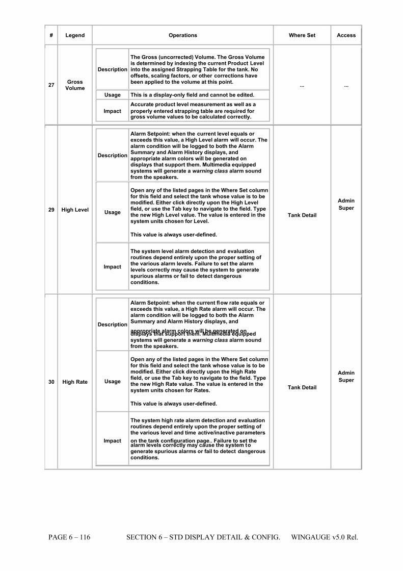
7/16/2019 3900 Manual
http://slidepdf.com/reader/full/3900-manual 164/266
PAGE 6 – 116 SECTION 6 – STD DISPLAY DETAIL & CONFIG. WINGAUGE v5.0 Rel.
# Legend Operations Where Set Access
27 GrossVolume
Description
The Gross (uncorrected) Volume. The Gross Volumeis determined by indexing the current Product Levelinto the assigned Strapping Table for the tank. Nooffsets, scaling factors, or other corrections havebeen applied to the volume at this point.
Usage This is a display-only field and cannot be edited.
Impact
Accurate product level measurement as well as a
properly entered strapping table are required for gross volume values to be calculated correctly.
... ...
29 High Level
Description
Alarm Setpoint: when the current level equals or exceeds this value, a High Level alarm will occur. Thealarm condition will be logged to both the AlarmSummary and Alarm History displays, andappropriate alarm colors will be generated ondisplays that support them. Multimedia equippedsystems will generate a warning class alarm soundfrom the speakers.
Usage
Open any of the listed pages in the Where Set columnfor this field and select the tank whose value is to bemodified. Either click directly upon the High Levelfield, or use the Tab key to navigate to the field. Typethe new High Level value. The value is entered in thesystem units chosen for Level.
This value is always user-defined.
Impact
The system level alarm detection and evaluationroutines depend entirely upon the proper setting of the various alarm levels. Failure to set the alarmlevels correctly may cause the system to generatespurious alarms or fail to detect dangerousconditions.
Tank Detail
Admin
Super
30 High Rate
Description
Alarm Setpoint: when the current flow rate equals or exceeds this value, a High Rate alarm will occur. Thealarm condition will be logged to both the AlarmSummary and Alarm History displays, and
appropriate alarm colors will be generated ondisplays that support them. Multimedia equippedsystems will generate a warning class alarm soundfrom the speakers.
Usage
Open any of the listed pages in the Where Set columnfor this field and select the tank whose value is to bemodified. Either click directly upon the High Ratefield, or use the Tab key to navigate to the field. Typethe new High Rate value. The value is entered in thesystem units chosen for Rates.
This value is always user-defined.
Impact
The system high rate alarm detection and evaluationroutines depend entirely upon the proper setting of the various level and time active/inactive parameters
on the tank configuration page.. Failure to set thealarm levels correctly may cause the system togenerate spurious alarms or fail to detect dangerousconditions.
Tank Detail
Admin
Super
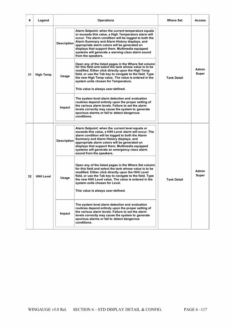
7/16/2019 3900 Manual
http://slidepdf.com/reader/full/3900-manual 165/266
WINGAUGE v5.0 Rel. SECTION 6 – STD DISPLAY DETAIL & CONFIG. PAGE 6 –117
# Legend Operations Where Set Access
31 High Temp
Description
Alarm Setpoint: when the current temperature equalsor exceeds this value, a High Temperature alarm willoccur. The alarm condition will be logged to both theAlarm Summary and Alarm History displays, andappropriate alarm colors will be generated ondisplays that support them. Multimedia equippedsystems will generate a warning class alarm soundfrom the speakers.
Usage
Open any of the listed pages in the Where Set columnfor this field and select the tank whose value is to bemodified. Either click directly upon the High Tempfield, or use the Tab key to navigate to the field. Typethe new High Temp value. The value is entered in thesystem units chosen for Temperature.
This value is always user-defined.
Impact
The system level alarm detection and evaluationroutines depend entirely upon the proper setting of the various alarm levels. Failure to set the alarmlevels correctly may cause the system to generatespurious alarms or fail to detect dangerousconditions.
Tank Detail
Admin
Super
32 HiHi Level
Description
Alarm Setpoint: when the current level equals or exceeds this value, a HiHi Level alarm will occur. Thealarm condition will be logged to both the AlarmSummary and Alarm History displays, andappropriate alarm colors will be generated ondisplays that support them. Multimedia equippedsystems will generate an emergency class alarmsound from the speakers.
Usage
Open any of the listed pages in the Where Set columnfor this field and select the tank whose value is to bemodified. Either click directly upon the HiHi Levelfield, or use the Tab key to navigate to the field. Typethe new HiHi Level value. The value is entered in thesystem units chosen for Level.
This value is always user-defined.
Impact
The system level alarm detection and evaluationroutines depend entirely upon the proper setting of the various alarm levels. Failure to set the alarmlevels correctly may cause the system to generatespurious alarms or fail to detect dangerousconditions.
Tank Detail
Admin
Super
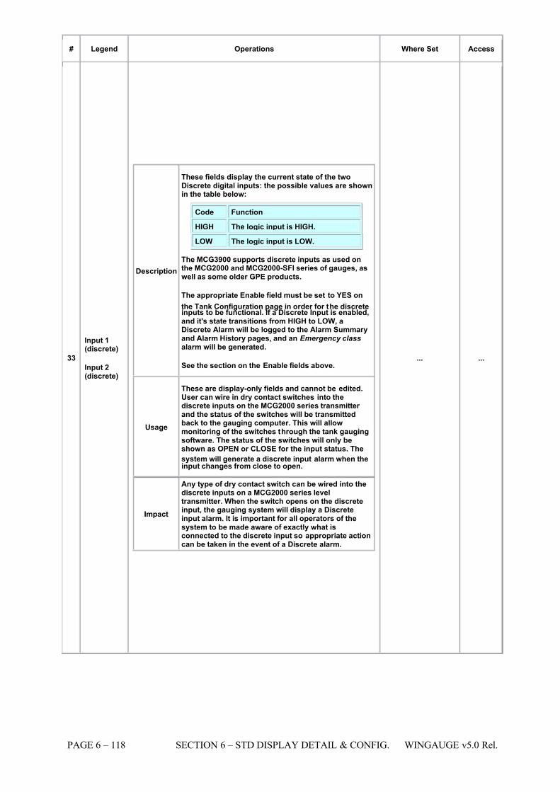
7/16/2019 3900 Manual
http://slidepdf.com/reader/full/3900-manual 166/266
PAGE 6 – 118 SECTION 6 – STD DISPLAY DETAIL & CONFIG. WINGAUGE v5.0 Rel.
# Legend Operations Where Set Access
33
Input 1(discrete)
Input 2(discrete)
Description
These fields display the current state of the twoDiscrete digital inputs: the possible values are shownin the table below:
Code Function
HIGH The logic input is HIGH.
LOW The logic input is LOW.
The MCG3900 supports discrete inputs as used onthe MCG2000 and MCG2000-SFI series of gauges, aswell as some older GPE products.
The appropriate Enable field must be set to YES on
the Tank Configuration page in order for the discreteinputs to be functional. If a Discrete Input is enabled,and it's state transitions from HIGH to LOW, aDiscrete Alarm will be logged to the Alarm Summaryand Alarm History pages, and an Emergency class alarm will be generated.
See the section on the Enable fields above.
Usage
These are display-only fields and cannot be edited.User can wire in dry contact switches into thediscrete inputs on the MCG2000 series transmitter and the status of the switches will be transmittedback to the gauging computer. This will allowmonitoring of the switches through the tank gaugingsoftware. The status of the switches will only beshown as OPEN or CLOSE for the input status. The
system will generate a discrete input alarm when theinput changes from close to open.
Impact
Any type of dry contact switch can be wired into thediscrete inputs on a MCG2000 series leveltransmitter. When the switch opens on the discreteinput, the gauging system will display a Discreteinput alarm. It is important for all operators of thesystem to be made aware of exactly what isconnected to the discrete input so appropriate actioncan be taken in the event of a Discrete alarm.
... ...
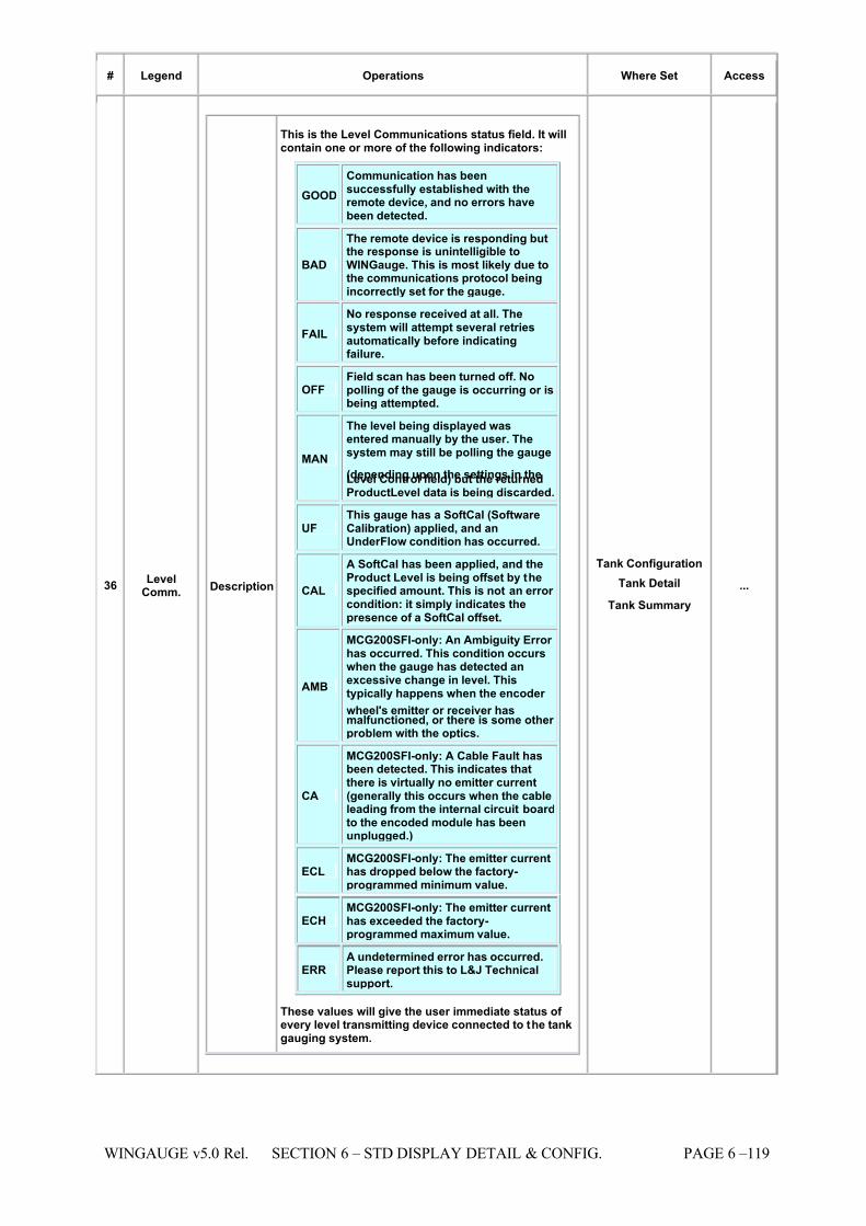
7/16/2019 3900 Manual
http://slidepdf.com/reader/full/3900-manual 167/266
WINGAUGE v5.0 Rel. SECTION 6 – STD DISPLAY DETAIL & CONFIG. PAGE 6 –119
# Legend Operations Where Set Access
36 LevelComm. Description
This is the Level Communications status field. It willcontain one or more of the following indicators:
GOOD Communication has beensuccessfully established with theremote device, and no errors havebeen detected.
BAD
The remote device is responding butthe response is unintelligible toWINGauge. This is most likely due tothe communications protocol beingincorrectly set for the gauge.
FAIL No response received at all. Thesystem will attempt several retriesautomatically before indicatingfailure.
OFF Field scan has been turned off. Nopolling of the gauge is occurring or isbeing attempted.
MAN
The level being displayed wasentered manually by the user. Thesystem may still be polling the gauge
(depending upon the settings in theLevel Control field) but the returnedProductLevel data is being discarded.
UF This gauge has a SoftCal (SoftwareCalibration) applied, and anUnderFlow condition has occurred.
CAL
A SoftCal has been applied, and theProduct Level is being offset by thespecified amount. This is not an error condition: it simply indicates thepresence of a SoftCal offset.
AMB
MCG200SFI-only: An Ambiguity Error has occurred. This condition occurswhen the gauge has detected anexcessive change in level. Thistypically happens when the encoder
wheel's emitter or receiver hasmalfunctioned, or there is some other problem with the optics.
CA
MCG200SFI-only: A Cable Fault hasbeen detected. This indicates thatthere is virtually no emitter current(generally this occurs when the cableleading from the internal circuit boardto the encoded module has beenunplugged.)
ECL MCG200SFI-only: The emitter currenthas dropped below the factory-programmed minimum value.
ECH MCG200SFI-only: The emitter currenthas exceeded the factory-programmed maximum value.
ERR A undetermined error has occurred.Please report this to L&J Technicalsupport.
These values will give the user immediate status of every level transmitting device connected to the tankgauging system.
Tank Configuration Tank Detail
Tank Summary ...
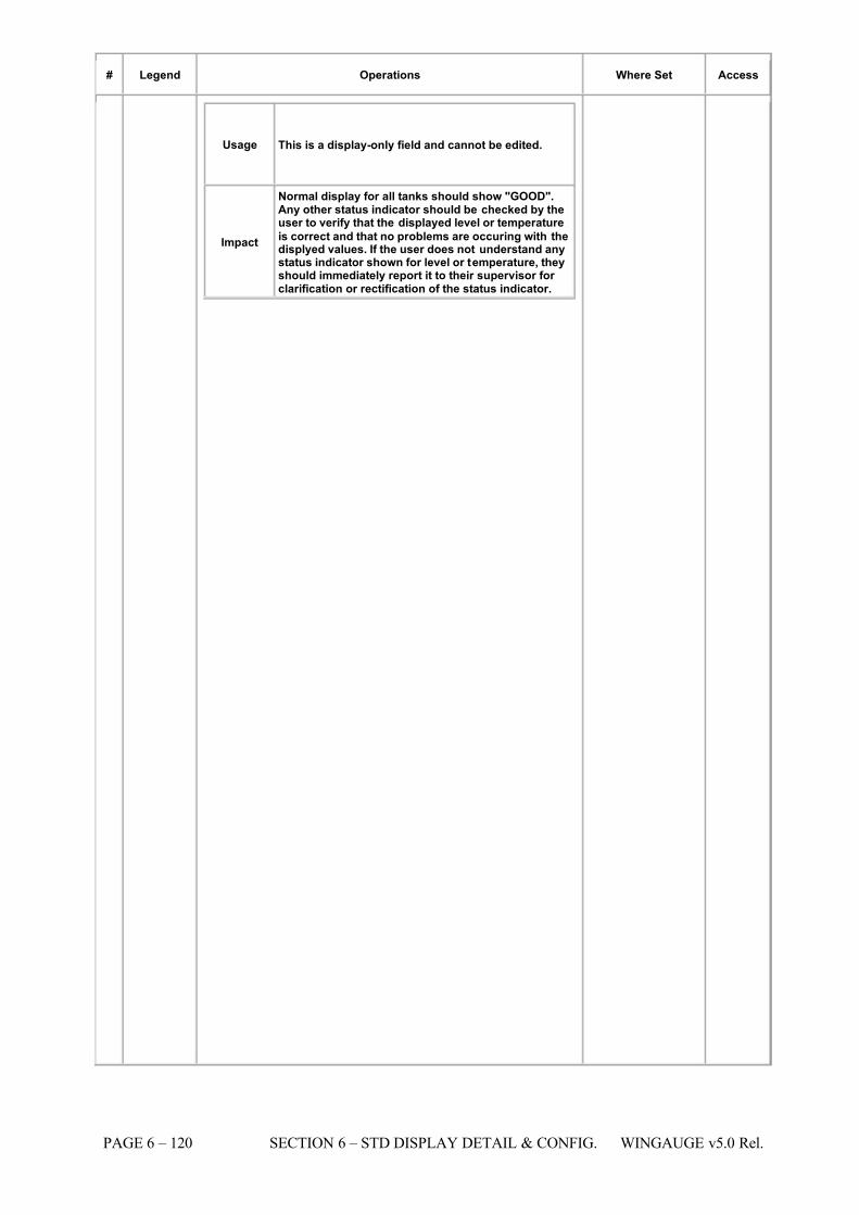
7/16/2019 3900 Manual
http://slidepdf.com/reader/full/3900-manual 168/266
PAGE 6 – 120 SECTION 6 – STD DISPLAY DETAIL & CONFIG. WINGAUGE v5.0 Rel.
# Legend Operations Where Set Access
Usage This is a display-only field and cannot be edited.
Impact
Normal display for all tanks should show "GOOD".Any other status indicator should be checked by theuser to verify that the displayed level or temperature
is correct and that no problems are occuring with thedisplyed values. If the user does not understand anystatus indicator shown for level or temperature, theyshould immediately report it to their supervisor for clarification or rectification of the status indicator.
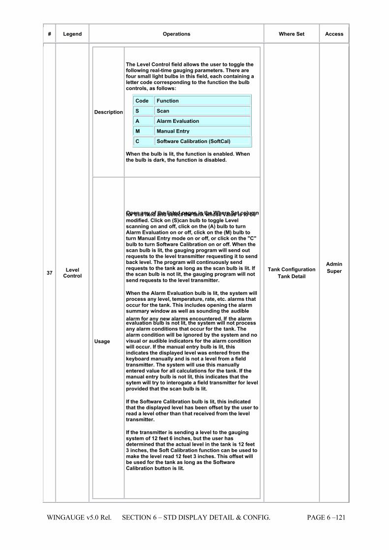
7/16/2019 3900 Manual
http://slidepdf.com/reader/full/3900-manual 169/266
WINGAUGE v5.0 Rel. SECTION 6 – STD DISPLAY DETAIL & CONFIG. PAGE 6 –121
# Legend Operations Where Set Access
37 LevelControl
Description
The Level Control field allows the user to toggle thefollowing real-time gauging parameters. There arefour small light bulbs in this field, each containing aletter code corresponding to the function the bulbcontrols, as follows:
Code Function
S Scan
A Alarm Evaluation
M Manual Entry
C Software Calibration (SoftCal)
When the bulb is lit, the function is enabled. Whenthe bulb is dark, the function is disabled.
Usage
Open any of the listed pages in the Where Set columnfor this field and select the tank whose value is to bemodified. Click on (S)can bulb to toggle Levelscanning on and off, click on the (A) bulb to turnAlarm Evaluation on or off, click on the (M) bulb toturn Manual Entry mode on or off, or click on the "C"bulb to turn Software Calibration on or off. When thescan bulb is lit, the gauging program will send outrequests to the level transmitter requesting it to sendback level. The program will continuously sendrequests to the tank as long as the scan bulb is lit. If the scan bulb is not lit, the gauging program will not
send requests to the level transmitter.
When the Alarm Evaluation bulb is lit, the system willprocess any level, temperature, rate, etc. alarms thatoccur for the tank. This includes opening the alarmsummary window as well as sounding the audible
alarm for any new alarms encountered. If the alarmevaluation bulb is not lit, the system will not processany alarm conditions that occur for the tank. Thealarm condition will be ignored by the system and novisual or audible indicators for the alarm conditionwill occur. If the manual entry bulb is lit, thisindicates the displayed level was entered from thekeyboard manually and is not a level from a fieldtransmitter. The system will use this manuallyentered value for all calculations for the tank. If themanual entry bulb is not lit, this indicates that thesytem will try to interogate a field transmitter for level
provided that the scan bulb is lit.
If the Software Calibration bulb is lit, this indicatedthat the displayed level has been offset by the user toread a level other than that received from the leveltransmitter.
If the transmitter is sending a level to the gaugingsystem of 12 feet 6 inches, but the user hasdetermined that the actual level in the tank is 12 feet3 inches, the Soft Calibration function can be used tomake the level read 12 feet 3 inches. This offset willbe used for the tank as long as the SoftwareCalibration button is lit.
Tank Configuration Tank Detail
Admin
Super
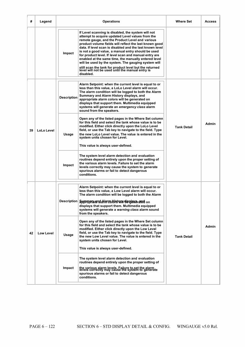
7/16/2019 3900 Manual
http://slidepdf.com/reader/full/3900-manual 170/266
PAGE 6 – 122 SECTION 6 – STD DISPLAY DETAIL & CONFIG. WINGAUGE v5.0 Rel.
# Legend Operations Where Set Access
Impact
If Level scanning is disabled, the system will notattempt to acquire updated Level values from theremote gauge, and the Product Level and variousproduct volume fields will reflect the last known gooddata. If level scan is disabled and the last known levelis not a good value, a manual entry should be usedfor product level. If level scan and manual entry areenabled at the same time, the manually entered levelwill be used by the system. The gauging system will
still scan the tank for product level but the returnedlevel will not be used until the manual entry isdisabled.
39 LoLo Level
Description
Alarm Setpoint: when the current level is equal to or less than this value, a LoLo Level alarm will occur.The alarm condition will be logged to both the AlarmSummary and Alarm History displays, andappropriate alarm colors will be generated ondisplays that support them. Multimedia equippedsystems will generate an emergency class alarmsound from the speakers.
Usage
Open any of the listed pages in the Where Set columnfor this field and select the tank whose value is to bemodified. Either click directly upon the LoLo Levelfield, or use the Tab key to navigate to the field. Type
the new LoLo Level value. The value is entered in thesystem units chosen for Level.
This value is always user-defined.
Impact
The system level alarm detection and evaluationroutines depend entirely upon the proper setting of the various alarm levels. Failure to set the alarmlevels correctly may cause the system to generatespurious alarms or fail to detect dangerous
conditions.
Tank Detail Admin
42 Low Level
Description
Alarm Setpoint: when the current level is equal to or less than this value, a Low Level alarm will occur.The alarm condition will be logged to both the Alarm
Summary and Alarm History displays, andappropriate alarm colors will be generated ondisplays that support them. Multimedia equippedsystems will generate a warning class alarm soundfrom the speakers.
Usage
Open any of the listed pages in the Where Set columnfor this field and select the tank whose value is to bemodified. Either click directly upon the Low Levelfield, or use the Tab key to navigate to the field. Typethe new Low Level value. The value is entered in thesystem units chosen for Level.
This value is always user-defined.
Impact
The system level alarm detection and evaluationroutines depend entirely upon the proper setting of
the various alarm levels. Failure to set the alarmlevels correctly may cause the system to generatespurious alarms or fail to detect dangerousconditions.
Tank Detail
Admin
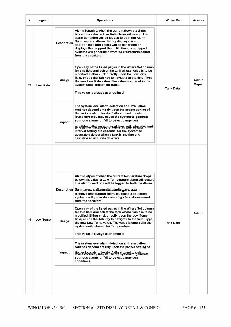
7/16/2019 3900 Manual
http://slidepdf.com/reader/full/3900-manual 171/266
WINGAUGE v5.0 Rel. SECTION 6 – STD DISPLAY DETAIL & CONFIG. PAGE 6 –123
# Legend Operations Where Set Access
43 Low Rate
Description
Alarm Setpoint: when the current flow rate dropsbelow this value, a Low Rate alarm will occur. Thealarm condition will be logged to both the AlarmSummary and Alarm History displays, andappropriate alarm colors will be generated ondisplays that support them. Multimedia equippedsystems will generate a warning class alarm soundfrom the speakers.
Usage
Open any of the listed pages in the Where Set columnfor this field and select the tank whose value is to bemodified. Either click directly upon the Low Ratefield, or use the Tab key to navigate to the field. Typethe new Low Rate value. The value is entered in thesystem units chosen for Rates.
This value is always user-defined.
Impact
The system level alarm detection and evaluationroutines depend entirely upon the proper setting of the various alarm levels. Failure to set the alarmlevels correctly may cause the system to generatespurious alarms or fail to detect dangerous
conditions. Proper setting of level active/inactive andtime active/inactive parameters as well as Rateinterval setting are essential for the system toaccurately detect when a tank is moving andcalculate an accurate flow rate.
Tank Detail
Admin
Super
44 Low Temp
Description
Alarm Setpoint: when the current temperature dropsbelow this value, a Low Temperature alarm will occur.The alarm condition will be logged to both the Alarm
Summary and Alarm History displays, andappropriate alarm colors will be generated ondisplays that support them. Multimedia equippedsystems will generate a warning class alarm soundfrom the speakers.
Usage
Open any of the listed pages in the Where Set columnfor this field and select the tank whose value is to bemodified. Either click directly upon the Low Tempfield, or use the Tab key to navigate to the field. Typethe new Low Temp value. The value is entered in thesystem units chosen for Temperature.
This value is always user-defined.
Impact
The system level alarm detection and evaluationroutines depend entirely upon the proper setting of
the various alarm levels. Failure to set the alarmlevels correctly may cause the system to generatespurious alarms or fail to detect dangerousconditions.
Tank Detail
Admin
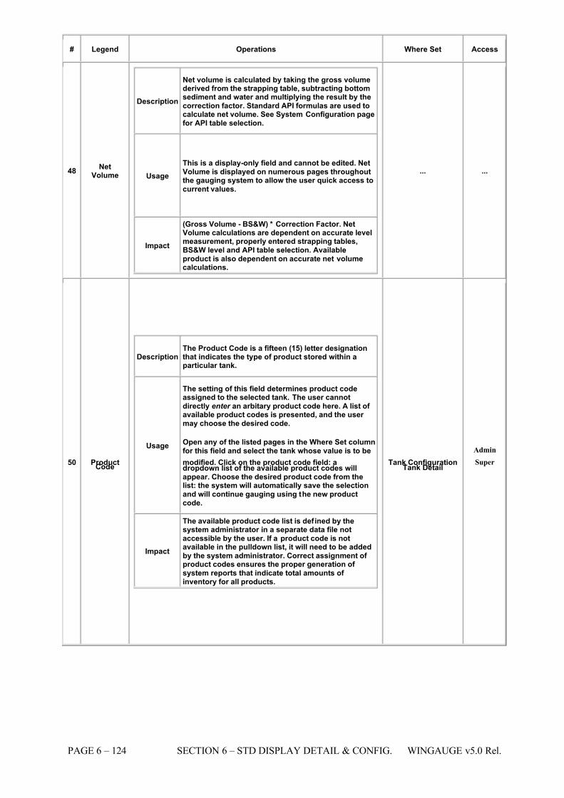
7/16/2019 3900 Manual
http://slidepdf.com/reader/full/3900-manual 172/266
PAGE 6 – 124 SECTION 6 – STD DISPLAY DETAIL & CONFIG. WINGAUGE v5.0 Rel.
# Legend Operations Where Set Access
48 NetVolume
Description
Net volume is calculated by taking the gross volumederived from the strapping table, subtracting bottomsediment and water and multiplying the result by thecorrection factor. Standard API formulas are used tocalculate net volume. See System Configuration pagefor API table selection.
Usage This is a display-only field and cannot be edited. NetVolume is displayed on numerous pages throughoutthe gauging system to allow the user quick access tocurrent values.
Impact
(Gross Volume - BS&W) * Correction Factor. NetVolume calculations are dependent on accurate levelmeasurement, properly entered strapping tables,BS&W level and API table selection. Availableproduct is also dependent on accurate net volumecalculations.
... ...
50 ProductCode
Description The Product Code is a fifteen (15) letter designationthat indicates the type of product stored within aparticular tank.
Usage
The setting of this field determines product codeassigned to the selected tank. The user cannotdirectly enter an arbitary product code here. A list of available product codes is presented, and the user may choose the desired code.
Open any of the listed pages in the Where Set columnfor this field and select the tank whose value is to be
modified. Click on the product code field: adropdown list of the available product codes willappear. Choose the desired product code from thelist: the system will automatically save the selectionand will continue gauging using the new productcode.
Impact
The available product code list is defined by thesystem administrator in a separate data file notaccessible by the user. If a product code is notavailable in the pulldown list, it will need to be addedby the system administrator. Correct assignment of product codes ensures the proper generation of system reports that indicate total amounts of inventory for all products.
Tank Configuration Tank Detail
Admin
Super
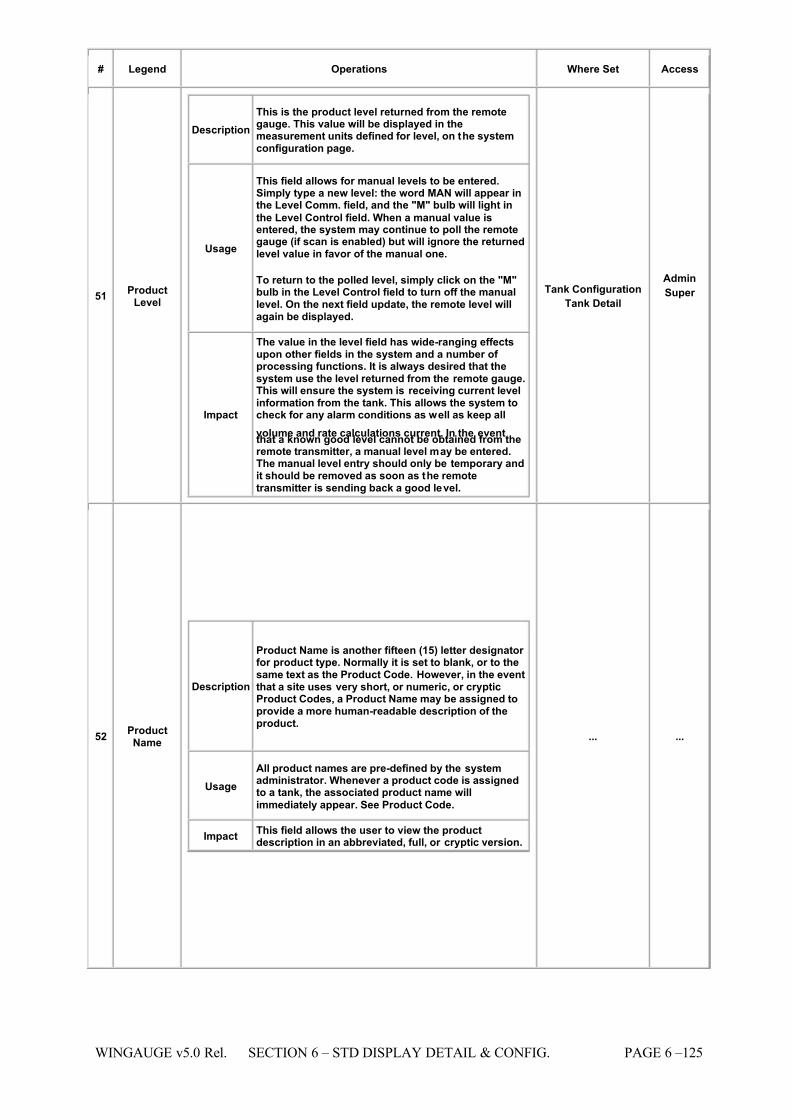
7/16/2019 3900 Manual
http://slidepdf.com/reader/full/3900-manual 173/266
WINGAUGE v5.0 Rel. SECTION 6 – STD DISPLAY DETAIL & CONFIG. PAGE 6 –125
# Legend Operations Where Set Access
51 ProductLevel
Description This is the product level returned from the remotegauge. This value will be displayed in themeasurement units defined for level, on the systemconfiguration page.
Usage
This field allows for manual levels to be entered.Simply type a new level: the word MAN will appear inthe Level Comm. field, and the "M" bulb will light in
the Level Control field. When a manual value isentered, the system may continue to poll the remotegauge (if scan is enabled) but will ignore the returnedlevel value in favor of the manual one.
To return to the polled level, simply click on the "M"bulb in the Level Control field to turn off the manuallevel. On the next field update, the remote level willagain be displayed.
Impact
The value in the level field has wide-ranging effectsupon other fields in the system and a number of processing functions. It is always desired that thesystem use the level returned from the remote gauge.This will ensure the system is receiving current levelinformation from the tank. This allows the system tocheck for any alarm conditions as well as keep all
volume and rate calculations current. In the eventthat a known good level cannot be obtained from theremote transmitter, a manual level may be entered.The manual level entry should only be temporary andit should be removed as soon as the remotetransmitter is sending back a good level.
Tank Configuration Tank Detail
Admin
Super
52 ProductName
Description
Product Name is another fifteen (15) letter designator for product type. Normally it is set to blank, or to thesame text as the Product Code. However, in the eventthat a site uses very short, or numeric, or crypticProduct Codes, a Product Name may be assigned toprovide a more human-readable description of theproduct.
Usage All product names are pre-defined by the systemadministrator. Whenever a product code is assignedto a tank, the associated product name will
immediately appear. See Product Code.
Impact This field allows the user to view the productdescription in an abbreviated, full, or cryptic version.
... ...
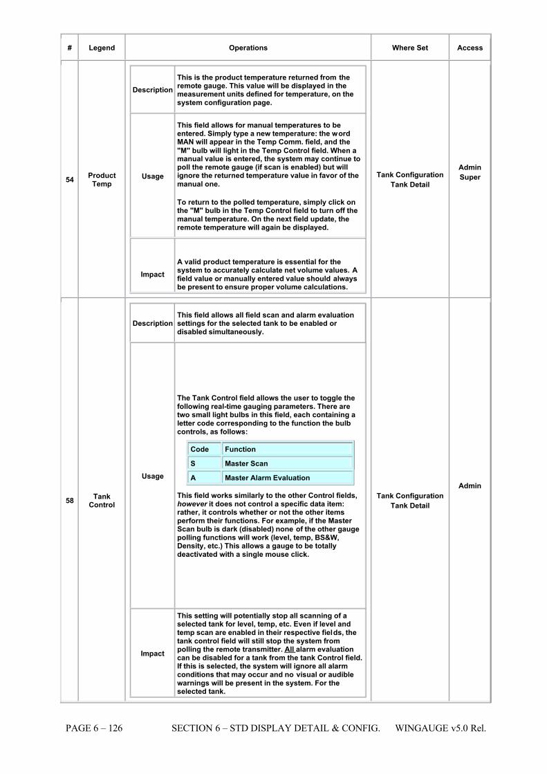
7/16/2019 3900 Manual
http://slidepdf.com/reader/full/3900-manual 174/266
PAGE 6 – 126 SECTION 6 – STD DISPLAY DETAIL & CONFIG. WINGAUGE v5.0 Rel.
# Legend Operations Where Set Access
54 ProductTemp
Description This is the product temperature returned from theremote gauge. This value will be displayed in themeasurement units defined for temperature, on thesystem configuration page.
Usage
This field allows for manual temperatures to beentered. Simply type a new temperature: the wordMAN will appear in the Temp Comm. field, and the
"M" bulb will light in the Temp Control field. When amanual value is entered, the system may continue topoll the remote gauge (if scan is enabled) but willignore the returned temperature value in favor of the
manual one.
To return to the polled temperature, simply click onthe "M" bulb in the Temp Control field to turn off themanual temperature. On the next field update, theremote temperature will again be displayed.
Impact A valid product temperature is essential for thesystem to accurately calculate net volume values. Afield value or manually entered value should alwaysbe present to ensure proper volume calculations.
Tank Configuration Tank Detail
Admin
Super
58 TankControl
Description This field allows all field scan and alarm evaluationsettings for the selected tank to be enabled or disabled simultaneously.
Usage
The Tank Control field allows the user to toggle thefollowing real-time gauging parameters. There aretwo small light bulbs in this field, each containing aletter code corresponding to the function the bulbcontrols, as follows:
Code Function S Master Scan
A Master Alarm Evaluation
This field works similarly to the other Control fields,however it does not control a specific data item:rather, it controls whether or not the other itemsperform their functions. For example, if the Master Scan bulb is dark (disabled) none of the other gaugepolling functions will work (level, temp, BS&W,Density, etc.) This allows a gauge to be totallydeactivated with a single mouse click.
Impact
This setting will potentially stop all scanning of aselected tank for level, temp, etc. Even if level andtemp scan are enabled in their respective fields, thetank control field will still stop the system frompolling the remote transmitter. All alarm evaluationcan be disabled for a tank from the tank Control field.If this is selected, the system will ignore all alarmconditions that may occur and no visual or audiblewarnings will be present in the system. For theselected tank.
Tank Configuration Tank Detail
Admin
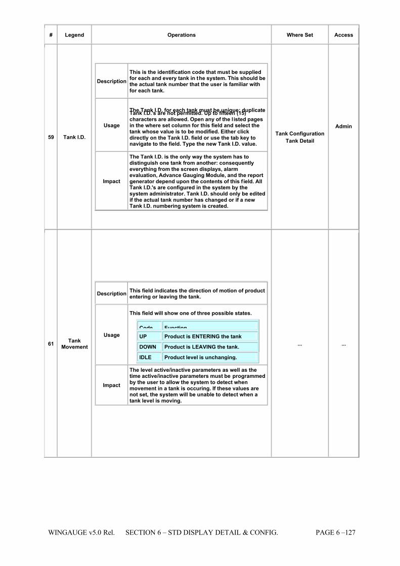
7/16/2019 3900 Manual
http://slidepdf.com/reader/full/3900-manual 175/266
WINGAUGE v5.0 Rel. SECTION 6 – STD DISPLAY DETAIL & CONFIG. PAGE 6 –127
# Legend Operations Where Set Access
59 Tank I.D.
Description This is the identification code that must be suppliedfor each and every tank in the system. This should bethe actual tank number that the user is familiar with
for each tank.
Usage
The Tank I.D. for each tank must be unique: duplicateTank I.D.'s are not permitted. Up to fifteen (15)characters are allowed. Open any of the l isted pagesin the where set column for this field and select thetank whose value is to be modified. Either clickdirectly on the Tank I.D. field or use the tab key tonavigate to the field. Type the new Tank I.D. value.
Impact
The Tank I.D. is the only way the system has todistinguish one tank from another: consequentlyeverything from the screen displays, alarmevaluation, Advance Gauging Module, and the reportgenerator depend upon the contents of this f ield. AllTank I.D.'s are configured in the system by thesystem administrator. Tank I.D. should only be editedif the actual tank number has changed or if a newTank I.D. numbering system is created.
Tank Configuration Tank Detail
Admin
61 TankMovement
Description This field indicates the direction of motion of productentering or leaving the tank.
Usage
This field will show one of three possible states.
Code Function UP Product is ENTERING the tank
DOWN Product is LEAVING the tank.
IDLE Product level is unchanging.
Impact
The level active/inactive parameters as well as thetime active/inactive parameters must be programmedby the user to allow the system to detect whenmovement in a tank is occuring. If these values arenot set, the system will be unable to detect when atank level is moving.
... ...
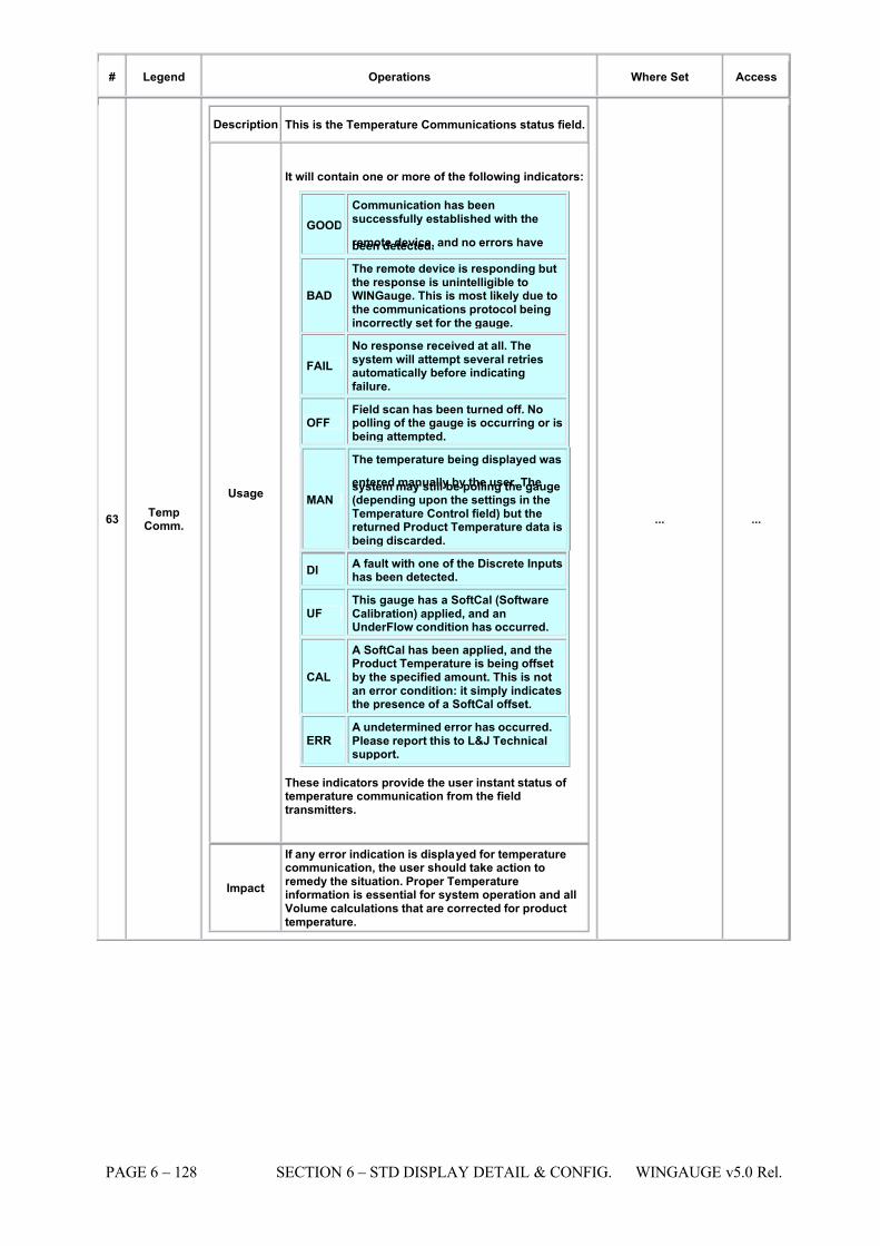
7/16/2019 3900 Manual
http://slidepdf.com/reader/full/3900-manual 176/266
PAGE 6 – 128 SECTION 6 – STD DISPLAY DETAIL & CONFIG. WINGAUGE v5.0 Rel.
# Legend Operations Where Set Access
63 TempComm.
Description This is the Temperature Communications status field.
Usage
It will contain one or more of the following indicators:
GOOD Communication has beensuccessfully established with the
remote device, and no errors havebeen detected.
BAD
The remote device is responding butthe response is unintelligible toWINGauge. This is most likely due tothe communications protocol beingincorrectly set for the gauge.
FAIL No response received at all. Thesystem will attempt several retriesautomatically before indicatingfailure.
OFF Field scan has been turned off. Nopolling of the gauge is occurring or isbeing attempted.
MAN
The temperature being displayed was
entered manually by the user. Thesystem may still be polling the gauge(depending upon the settings in theTemperature Control field) but thereturned Product Temperature data isbeing discarded.
DI A fault with one of the Discrete Inputshas been detected.
UF This gauge has a SoftCal (SoftwareCalibration) applied, and anUnderFlow condition has occurred.
CAL
A SoftCal has been applied, and theProduct Temperature is being offsetby the specified amount. This is notan error condition: it simply indicatesthe presence of a SoftCal offset.
ERR A undetermined error has occurred.Please report this to L&J Technicalsupport.
These indicators provide the user instant status of temperature communication from the fieldtransmitters.
Impact
If any error indication is displayed for temperaturecommunication, the user should take action toremedy the situation. Proper Temperatureinformation is essential for system operation and allVolume calculations that are corrected for producttemperature.
... ...
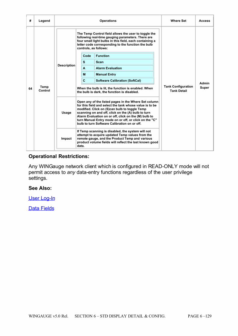
7/16/2019 3900 Manual
http://slidepdf.com/reader/full/3900-manual 177/266
WINGAUGE v5.0 Rel. SECTION 6 – STD DISPLAY DETAIL & CONFIG. PAGE 6 –129
# Legend Operations Where Set Access
64 TempControl
Description
The Temp Control field allows the user to toggle thefollowing real-time gauging parameters. There arefour small light bulbs in this field, each containing aletter code corresponding to the function the bulbcontrols, as follows:
Code Function
S
Scan
A Alarm Evaluation
M Manual Entry
C Software Calibration (SoftCal)
When the bulb is lit, the function is enabled. Whenthe bulb is dark, the function is disabled.
Usage
Open any of the listed pages in the Where Set columnfor this field and select the tank whose value is to bemodified. Click on (S)can bulb to toggle Tempscanning on and off, click on the (A) bulb to turnAlarm Evaluation on or off, click on the (M) bulb toturn Manual Entry mode on or off, or click on the "C"bulb to turn Software Calibration on or off.
Impact
If Temp scanning is disabled, the system will notattempt to acquire updated Temp values from theremote gauge, and the Product Temp and variousproduct volume fields will reflect the last known gooddata.
Tank Configuration Tank Detail
Admin
Super
Operational Restrictions:
Any WINGauge network client which is configured in READ-ONLY mode will notpermit access to any data-entry functions regardless of the user privilegesettings.
See Also:
User Log-In
Data Fields
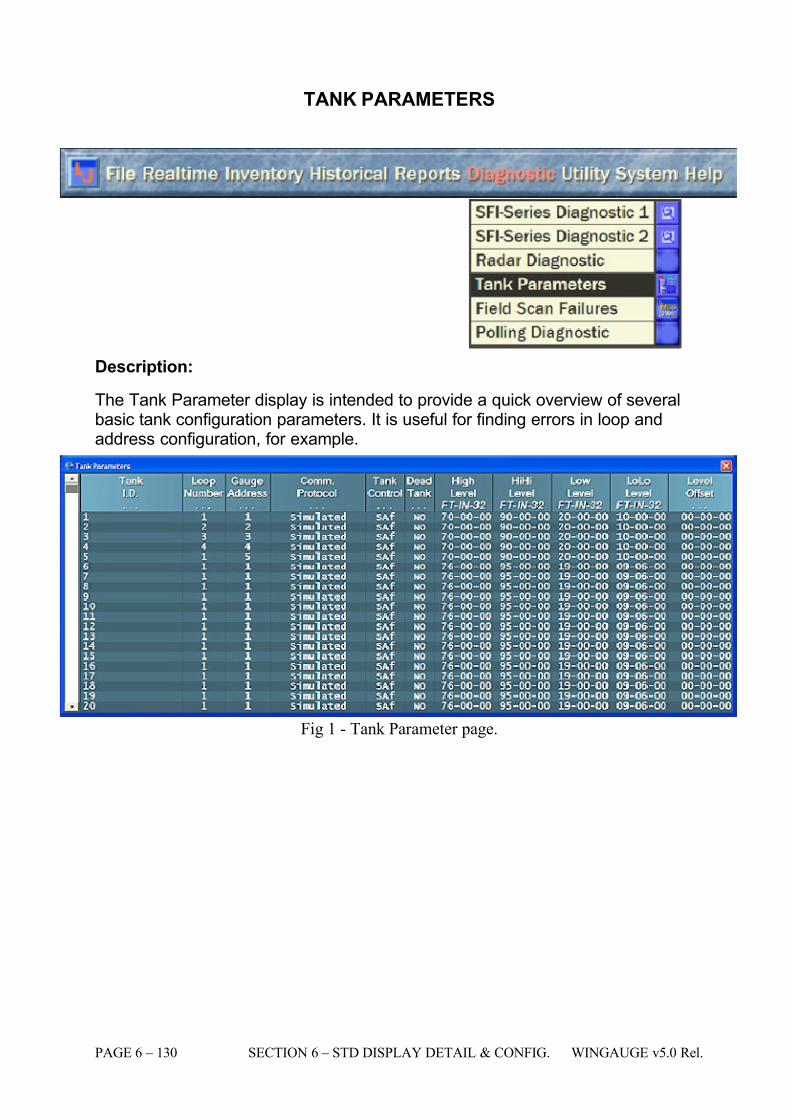
7/16/2019 3900 Manual
http://slidepdf.com/reader/full/3900-manual 178/266
PAGE 6 – 130 SECTION 6 – STD DISPLAY DETAIL & CONFIG. WINGAUGE v5.0 Rel.
TANK PARAMETERS
Description:
The Tank Parameter display is intended to provide a quick overview of severalbasic tank configuration parameters. It is useful for finding errors in loop andaddress configuration, for example.
Fig 1 - Tank Parameter page.
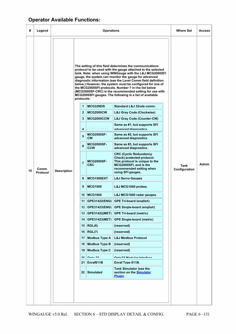
7/16/2019 3900 Manual
http://slidepdf.com/reader/full/3900-manual 179/266
WINGAUGE v5.0 Rel. SECTION 6 – STD DISPLAY DETAIL & CONFIG. PAGE 6 –131
Operator Available Functions:
# Legend Operations Where Set Access
10 Comm.Protocol Description
The setting of this field determines the communicationsprotocol to be used with the gauge attached to the selectedtank. Note: when using WINGauge with the L&J MCG2000SFIgauge, the system can monitor the gauge for advanceddiagnostic information (see the Level Comm field definitionbelow.) However, the system must be configured for one of the MCG2000SFI protocols. Number 7 in the list below(MCG2000SF-CRC) is the recommended setting for use withMCG2000SFI gauges. The following is a list of availableprotocols:
1 MCG32NDS Standard L&J 32nds comm.
2 MCG2000CW L&J Gray Code (Clockwise)
3 MCG2000CCW L&J Gray Code (Counter-CW)
4 MCG200SF-32
Same as #1, but supports SFI
advanced diagnostics. 5 MCG2000SF-
CW Same as #2, but supports SFIadvanced diagnostics.
6 MCG2000SF-CCW
Same as #3, but supports SFIadvanced diagnostics.
7 MCG2000SF-CRC
CRC (Cyclic RedundancyCheck) protected protocol.This protocol is unique to theMCG2000SFI, and is therecommended setting whenusing SFI gauges.
8 MCG1500EXT L&J Servo Gauges
9 MCG1000 L&J MCG1000 probes.
10 MCG1600 L&J MCG1600 radar gauges.
11 GPE31422(ENG) GPE Tri-board (english)
12 GPE31423(ENG) GPE Single-board (english)
13 GPE31422(MET) GPE Tri-board (metric)
14 GPE31423(MET) GPE Single-board (metric)
15 RGL(6) {reserved}
16 RGL(7) {reserved}
17 Modbus Type A L&J Modbus Protocol
18 Modbus Type B {reserved}
19 Modbus Type C {reserved}
20 Opto 22 Opto22 Modular Interface 21 Enraf811B Enraf Type 811B.
22 Simulated Tank Simulator (see thesection on the Simulator Plugin.
TankConfiguration
Admin
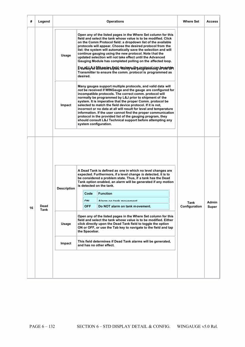
7/16/2019 3900 Manual
http://slidepdf.com/reader/full/3900-manual 180/266
PAGE 6 – 132 SECTION 6 – STD DISPLAY DETAIL & CONFIG. WINGAUGE v5.0 Rel.
# Legend Operations Where Set Access
Usage
Open any of the listed pages in the Where Set column for thisfield and select the tank whose value is to be modified. Clickon the Comm Protocol field: a dropdown list of the availableprotocols will appear. Choose the desired protocol from thelist: the system will automatically save the selection and willcontinue gauging using the new protocol. Note that theupdated selection will not take effect until the AdvancedGauging Module has completed polling on the affected loop.
For all L&J SFI series field devices, the protocol can be set toa variety of different styles. Verify the programming of the SFITransmitter to ensure the comm. protocol is programmed as
desired.
Impact
Many gauges support multiple protocols, and valid data willnot be received if WINGauge and the gauge are configured for incompatible protocols. The correct comm. protocol willnormally be programmed by L&J prior to shipment of thesystem. It is imperative that the proper Comm. protocol beselected to match the field device protocol. If it is not,incorrect or no data at all will result for level and temperatureinformation. If the user cannot find the proper communicationprotocol in the provided list of the gauging program, theyshould consult L&J Technical support before attempting any
system configuration.
16 DeadTank
Description
A Dead Tank is defined as one in which no level changes areexpected. Furthermore, if a level change is detected, it is tobe considered a problem state. Thus, if a tank has the DeadTank option enabled, an alarm will be generated if any motionis detected on the tank.
Code Function
ON Alarm on tank movement. OFF Do NOT alarm on tank movement.
Usage
Open any of the listed pages in the Where Set column for thisfield and select the tank whose value is to be modified. Either click directly upon the Dead Tank field to toggle the optionON or OFF, or use the Tab key to navigate to the field and tapthe Spacebar.
Impact This field determines if Dead Tank alarms will be generated,and has no other effect.
TankConfiguration
Admin
Super
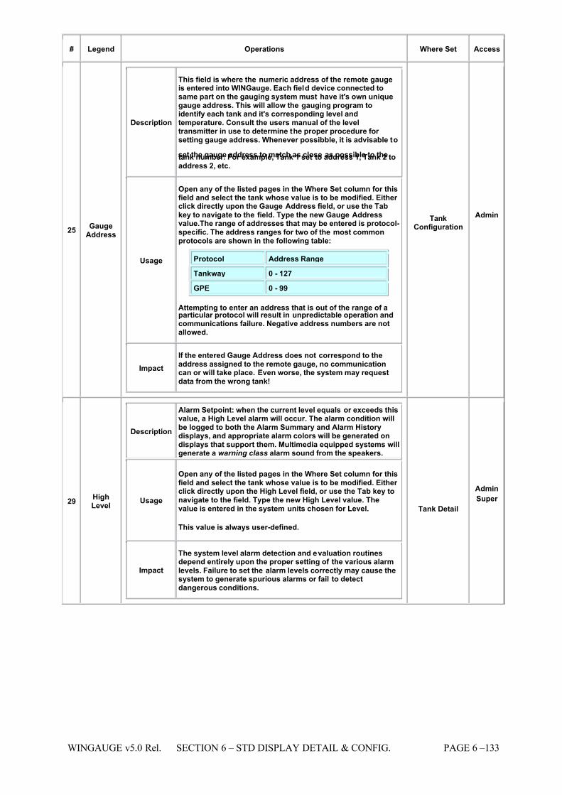
7/16/2019 3900 Manual
http://slidepdf.com/reader/full/3900-manual 181/266
WINGAUGE v5.0 Rel. SECTION 6 – STD DISPLAY DETAIL & CONFIG. PAGE 6 –133
# Legend Operations Where Set Access
25 GaugeAddress
Description
This field is where the numeric address of the remote gaugeis entered into WINGauge. Each field device connected tosame part on the gauging system must have it's own uniquegauge address. This will allow the gauging program toidentify each tank and it's corresponding level andtemperature. Consult the users manual of the leveltransmitter in use to determine the proper procedure for setting gauge address. Whenever possibble, it is advisable to
set the gauge address to match as close as possible to thetank number. For example, Tank 1 set to address 1, Tank 2 toaddress 2, etc.
Usage
Open any of the listed pages in the Where Set column for thisfield and select the tank whose value is to be modified. Either click directly upon the Gauge Address field, or use the Tabkey to navigate to the field. Type the new Gauge Addressvalue.The range of addresses that may be entered is protocol-specific. The address ranges for two of the most commonprotocols are shown in the following table:
Protocol Address Range
Tankway 0 - 127
GPE 0 - 99
Attempting to enter an address that is out of the range of aparticular protocol will result in unpredictable operation andcommunications failure. Negative address numbers are notallowed.
Impact If the entered Gauge Address does not correspond to theaddress assigned to the remote gauge, no communicationcan or will take place. Even worse, the system may requestdata from the wrong tank!
TankConfiguration
Admin
29 HighLevel
Description
Alarm Setpoint: when the current level equals or exceeds thisvalue, a High Level alarm will occur. The alarm condition willbe logged to both the Alarm Summary and Alarm Historydisplays, and appropriate alarm colors will be generated ondisplays that support them. Multimedia equipped systems willgenerate a warning class alarm sound from the speakers.
Usage
Open any of the listed pages in the Where Set column for thisfield and select the tank whose value is to be modified. Either click directly upon the High Level field, or use the Tab key tonavigate to the field. Type the new High Level value. Thevalue is entered in the system units chosen for Level.
This value is always user-defined.
Impact
The system level alarm detection and evaluation routinesdepend entirely upon the proper setting of the various alarmlevels. Failure to set the alarm levels correctly may cause thesystem to generate spurious alarms or fail to detectdangerous conditions.
Tank Detail
Admin
Super
7/16/2019 3900 Manual
http://slidepdf.com/reader/full/3900-manual 182/266
PAGE 6 – 134 SECTION 6 – STD DISPLAY DETAIL & CONFIG. WINGAUGE v5.0 Rel.
# Legend Operations Where Set Access
32 HiHiLevel
Description
Alarm Setpoint: when the current level equals or exceeds thisvalue, a HiHi Level alarm will occur. The alarm condition willbe logged to both the Alarm Summary and Alarm Historydisplays, and appropriate alarm colors will be generated ondisplays that support them. Multimedia equipped systems willgenerate an emergency class alarm sound from the speakers.
Usage
Open any of the listed pages in the Where Set column for thisfield and select the tank whose value is to be modified. Either
click directly upon the HiHi Level field, or use the Tab key tonavigate to the field. Type the new HiHi Level value. The valueis entered in the system units chosen for Level.
This value is always user-defined.
Impact
The system level alarm detection and evaluation routinesdepend entirely upon the proper setting of the various alarmlevels. Failure to set the alarm levels correctly may cause thesystem to generate spurious alarms or fail to detectdangerous conditions.
Tank Detail
AdminSuper
39 LoLoLevel
Description
Alarm Setpoint: when the current level is equal to or less thanthis value, a LoLo Level alarm will occur. The alarm conditionwill be logged to both the Alarm Summary and Alarm History
displays, and appropriate alarm colors will be generated ondisplays that support them. Multimedia equipped systems willgenerate an emergency class alarm sound from the speakers.
Usage
Open any of the listed pages in the Where Set column for thisfield and select the tank whose value is to be modified. Either click directly upon the LoLo Level field, or use the Tab key tonavigate to the field. Type the new LoLo Level value. Thevalue is entered in the system units chosen for Level.
This value is always user-defined.
Impact
The system level alarm detection and evaluation routinesdepend entirely upon the proper setting of the various alarmlevels. Failure to set the alarm levels correctly may cause thesystem to generate spurious alarms or fail to detect
dangerous conditions.
Tank Detail Admin
40 LoopNumber
Description
This field is where the numeric Loop Number of the remotegauge is entered into WINGauge. The loop numbers will bepre-defined by L&J Engineering and the user's systemadministrator. The gauging loop is the actual communicationport in the gauging computer that the field transmitters areconnected to. A typical connection would be to use serialports Com 1 or Com 2 for example.
Usage
Open any of the listed pages in the Where Set column for thisfield and select the tank whose value is to be modified. Either click directly upon the Loop Number field, or use the Tab keyto navigate to the field. Type the new Loop Number value.
Loop Numbers can range from 1 to 32 (WINGauge supports amaximum of 32 gauging loops.) Loops correspond to
physical interface ports, and the actual assignment of a LoopNumber to a physical port is determined by the system
administrator.
Impact
If the entered Loop Number does not correspond to aphysical communications port connected to a gauge loop, nocommunication can or will take place. It is entirely possible toset this number to a valid but incorrect loop, in which casethe system could record data from the wrong tanks.
TankConfiguration
Admin
7/16/2019 3900 Manual
http://slidepdf.com/reader/full/3900-manual 183/266
WINGAUGE v5.0 Rel. SECTION 6 – STD DISPLAY DETAIL & CONFIG. PAGE 6 –135
# Legend Operations Where Set Access
42 LowLevel
Description
Alarm Setpoint: when the current level is equal to or less thanthis value, a Low Level alarm will occur. The alarm conditionwill be logged to both the Alarm Summary and Alarm Historydisplays, and appropriate alarm colors will be generated ondisplays that support them. Multimedia equipped systems willgenerate a warning class alarm sound from the speakers.
Usage
Open any of the listed pages in the Where Set column for thisfield and select the tank whose value is to be modified. Either
click directly upon the Low Level f ield, or use the Tab key tonavigate to the field. Type the new Low Level value. The valueis entered in the system units chosen for Level.
This value is always user-defined.
Impact
The system level alarm detection and evaluation routinesdepend entirely upon the proper setting of the various alarmlevels. Failure to set the alarm levels correctly may cause thesystem to generate spurious alarms or fail to detectdangerous conditions.
Tank Detail
Admin
59 Tank I.D.
Description This is the identification code that must be supplied for eachand every tank in the system. This should be the actual tanknumber that the user is familiar with for each tank.
Usage
The Tank I.D. for each tank must be unique: duplicate TankI.D.'s are not permitted. Up to fifteen (15) characters areallowed. Open any of the listed pages in the where set columnfor this field and select the tank whose value is to bemodified. Either click directly on the Tank I.D. field or use thetab key to navigate to the field. Type the new Tank I.D. value.
Impact
The Tank I.D. is the only way the system has to distinguishone tank from another: consequently everything from thescreen displays, alarm evaluation, Advance Gauging Module,and the report generator depend upon the contents of thisfield. All Tank I.D.'s are configured in the system by thesystem administrator. Tank I.D. should only be edited if theactual tank number has changed or if a new Tank I.D.numbering system is created.
TankConfiguration
Tank Detail
Admin
Operational Restrictions:
NONE
See Also:
Data Fields
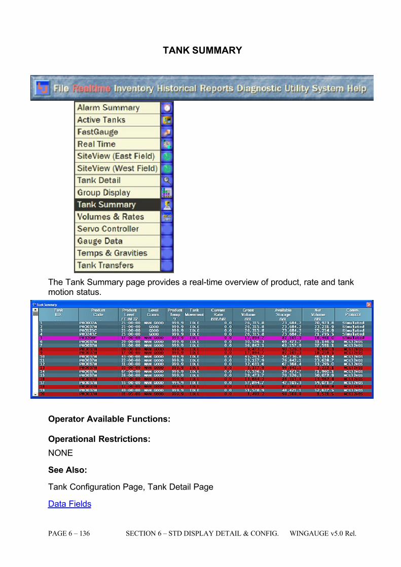
7/16/2019 3900 Manual
http://slidepdf.com/reader/full/3900-manual 184/266
PAGE 6 – 136 SECTION 6 – STD DISPLAY DETAIL & CONFIG. WINGAUGE v5.0 Rel.
TANK SUMMARY
The Tank Summary page provides a real-time overview of product, rate and tankmotion status.
Operator Available Functions:
Operational Restrictions:
NONE
See Also:
Tank Configuration Page, Tank Detail Page
Data Fields
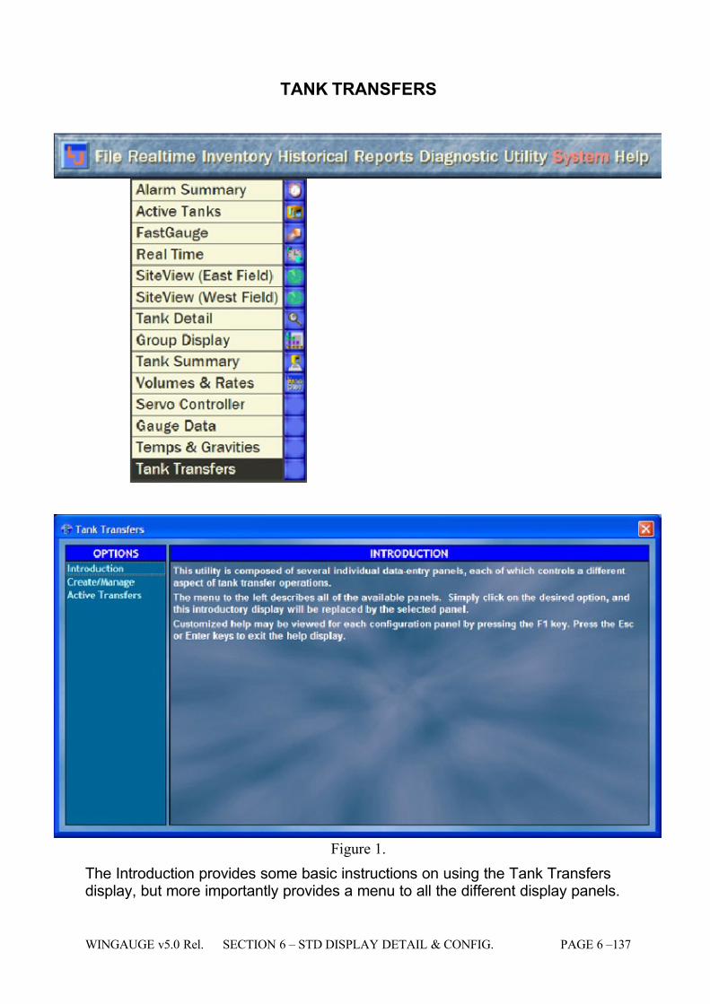
7/16/2019 3900 Manual
http://slidepdf.com/reader/full/3900-manual 185/266
WINGAUGE v5.0 Rel. SECTION 6 – STD DISPLAY DETAIL & CONFIG. PAGE 6 –137
TANK TRANSFERS
Figure 1.
The Introduction provides some basic instructions on using the Tank Transfersdisplay, but more importantly provides a menu to all the different display panels.
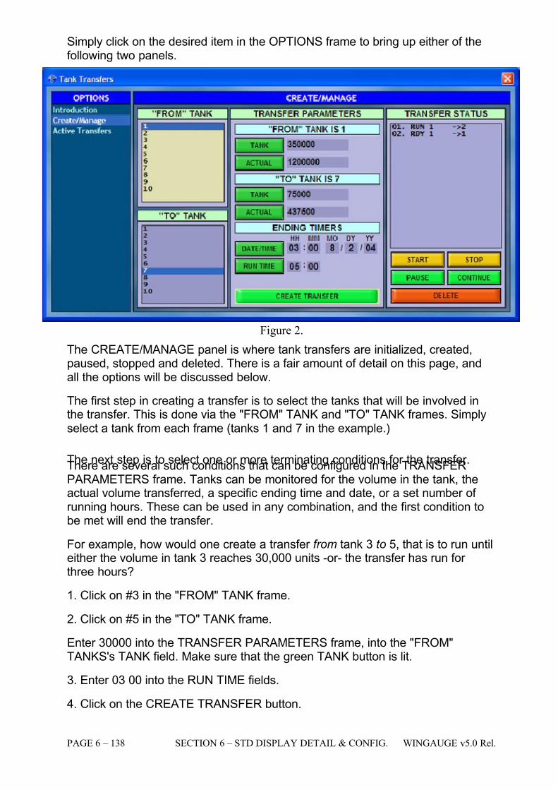
7/16/2019 3900 Manual
http://slidepdf.com/reader/full/3900-manual 186/266
PAGE 6 – 138 SECTION 6 – STD DISPLAY DETAIL & CONFIG. WINGAUGE v5.0 Rel.
Simply click on the desired item in the OPTIONS frame to bring up either of thefollowing two panels.
Figure 2.
The CREATE/MANAGE panel is where tank transfers are initialized, created,paused, stopped and deleted. There is a fair amount of detail on this page, andall the options will be discussed below.
The first step in creating a transfer is to select the tanks that will be involved inthe transfer. This is done via the "FROM" TANK and "TO" TANK frames. Simplyselect a tank from each frame (tanks 1 and 7 in the example.)
The next step is to select one or more terminating conditions for the transfer.There are several such conditions that can be configured in the TRANSFERPARAMETERS frame. Tanks can be monitored for the volume in the tank, theactual volume transferred, a specific ending time and date, or a set number of running hours. These can be used in any combination, and the first condition tobe met will end the transfer.
For example, how would one create a transfer from tank 3 to 5, that is to run untileither the volume in tank 3 reaches 30,000 units -or- the transfer has run for three hours?
1. Click on #3 in the "FROM" TANK frame.
2. Click on #5 in the "TO" TANK frame.
Enter 30000 into the TRANSFER PARAMETERS frame, into the "FROM"TANKS's TANK field. Make sure that the green TANK button is lit.
3. Enter 03 00 into the RUN TIME fields.
4. Click on the CREATE TRANSFER button.
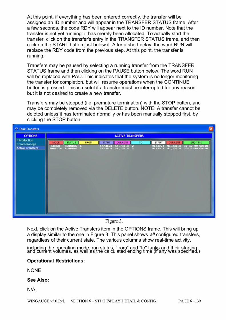
7/16/2019 3900 Manual
http://slidepdf.com/reader/full/3900-manual 187/266
WINGAUGE v5.0 Rel. SECTION 6 – STD DISPLAY DETAIL & CONFIG. PAGE 6 –139
At this point, if everything has been entered correctly, the transfer will beassigned an ID number and will appear in the TRANSFER STATUS frame. After a few seconds, the code RDY will appear next to the ID number. Note that thetransfer is not yet running: it has merely been allocated. To actually start thetransfer, click on the transfer's entry in the TRANSFER STATUS frame, and thenclick on the START button just below it. After a short delay, the word RUN willreplace the RDY code from the previous step. At this point, the transfer isrunning.
Transfers may be paused by selecting a running transfer from the TRANSFERSTATUS frame and then clicking on the PAUSE button below. The word RUNwill be replaced with PAU. This indicates that the system is no longer monitoringthe transfer for completion, but will resume operations when the CONTINUEbutton is pressed. This is useful if a transfer must be interrupted for any reasonbut it is not desired to create a new transfer.
Transfers may be stopped (i.e. premature termination) with the STOP button, andmay be completely removed via the DELETE button. NOTE: A transfer cannot bedeleted unless it has terminated normally or has been manually stopped first, byclicking the STOP button.
Figure 3.
Next, click on the Active Transfers item in the OPTIONS frame. This will bring upa display similar to the one in Figure 3. This panel shows all configured transfers,regardless of their current state. The various columns show real-time activity,
including the operating mode, run status, "from" and "to" tanks and their startingand current volumes, as well as the calculated ending time (if any was specified.)
Operational Restrictions:
NONE
See Also:
N/A
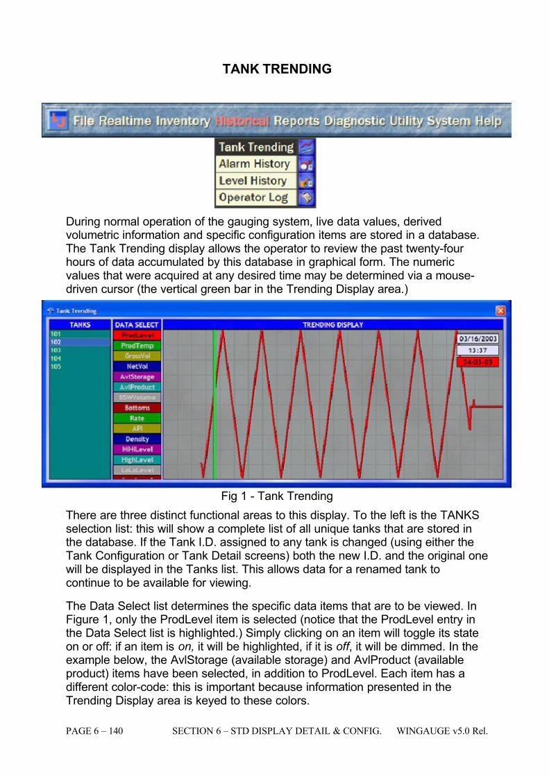
7/16/2019 3900 Manual
http://slidepdf.com/reader/full/3900-manual 188/266
PAGE 6 – 140 SECTION 6 – STD DISPLAY DETAIL & CONFIG. WINGAUGE v5.0 Rel.
TANK TRENDING
During normal operation of the gauging system, live data values, derivedvolumetric information and specific configuration items are stored in a database.The Tank Trending display allows the operator to review the past twenty-four hours of data accumulated by this database in graphical form. The numericvalues that were acquired at any desired time may be determined via a mouse-driven cursor (the vertical green bar in the Trending Display area.)
Fig 1 - Tank Trending
There are three distinct functional areas to this display. To the left is the TANKSselection list: this will show a complete list of all unique tanks that are stored inthe database. If the Tank I.D. assigned to any tank is changed (using either theTank Configuration or Tank Detail screens) both the new I.D. and the original onewill be displayed in the Tanks list. This allows data for a renamed tank tocontinue to be available for viewing.
The Data Select list determines the specific data items that are to be viewed. InFigure 1, only the ProdLevel item is selected (notice that the ProdLevel entry inthe Data Select list is highlighted.) Simply clicking on an item will toggle its stateon or off: if an item is on, it will be highlighted, if it is off , it will be dimmed. In theexample below, the AvlStorage (available storage) and AvlProduct (availableproduct) items have been selected, in addition to ProdLevel. Each item has adifferent color-code: this is important because information presented in theTrending Display area is keyed to these colors.
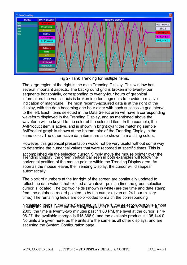
7/16/2019 3900 Manual
http://slidepdf.com/reader/full/3900-manual 189/266
WINGAUGE v5.0 Rel. SECTION 6 – STD DISPLAY DETAIL & CONFIG. PAGE 6 –141
Fig 2- Tank Trending for multiple items.
The large region at the right is the main Trending Display. This window hasseveral important aspects. The background grid is broken into twenty-four segments horizontally, corresponding to twenty-four hours of graphicalinformation: the vertical axis is broken into ten segments to provide a relativeindication of magnitude. The most recently-acquired data is at the right of thedisplay, with the data becoming one hour older with each successive grid intervalto the left. Each Items selected in the Data Select area will have a correspondingwaveform displayed in the Trending Display, and as mentioned above thewaveform will be keyed to the color of the selected item. In the example, the
AvlProduct item is active, and is shown in bright cyan: the matching sample AvlProduct graph is shown at the bottom third of the Trending Display in thesame color. The other active data items are also shown in matching colors.
However, this graphical presentation would not be very useful without some wayto determine the numerical values that were recorded at specific times. This is
accomplished via the selection cursor. Simply move the mouse pointer over theTrending Display: the green vertical bar seen in both examples will follow thehorizontal position of the mouse pointer within the Trending Display area. Assoon as the mouse leaves the Trending Display, the cursor will disappear automatically.
The block of numbers at the far right of the screen are continually updated toreflect the data values that existed at whatever point in time the green selectioncursor is located. The top two fields (shown in white) are the time and date stampfrom the database record pointed to by the cursor (given as 24-hour militarytime.) The remaining fields are color-coded to match the corresponding
highlighted items in the Data Select list. In Figure 1, the selection cursor is almostdirectly in the center of the Trending Display. The recorded date is March 16,2003, the time is twenty-two minutes past 11:00 PM, the level at the cursor is 14-06-27, the available storage is 615,368.0, and the available product is 105,144.0.No units are given here, as the units are the same as all other displays, and areset using the System Configuration page.
7/16/2019 3900 Manual
http://slidepdf.com/reader/full/3900-manual 190/266
PAGE 6 – 142 SECTION 6 – STD DISPLAY DETAIL & CONFIG. WINGAUGE v5.0 Rel.
Operator Available Functions:
# Legend Operations Where Set Access
3 AvailableProduct
Description
The volume of product actually available from the tank. Thisvalue is calculated by taking the bottom value entered by theend user and subtracting it from the Net Volume. This valueis not editable by the end user, but proper temperature andgravity values are required for the system to accuratelyderive Net Volume. This value is automatically updated by
the system whenever any measured or entered valueschange.
Usage This is a display-only field and cannot be edited.
Impact Available Product = (Net Volume - Bottom Volume)
... ...
4 AvailableStorage
Description
The volume of unused space available in the tank. This valueis calculated by taking the Total Tank Capacity entered bythe end user and subtracting the Gross Volume derived fromthe strapping table for the current tank level. The value isnot editable but will change as product level moves or if Total Capacity Value changes.
Usage This is a display-only field and cannot be edited. Definition (Total Volume - Gross Volume)
... ...
8 BS&WLevel
Description The level of water and sediment at the bottom of the tank(i.e., Bottom Sediment & Water.)
Usage
Open any of the listed pages in the Where Set column for this field and select the tank whose value is to be modified.Either click directly upon the BS&W Level field, or use theTab key to navigate to the field. Type the new BS&W Levelvalue. The value is entered in the system units chosen for Level.
This value is normally user-defined, but can be a live valuewhen using servo gauges or other devices capable of detecting the BS&W level. If a field device is used tomeasure the BS&W level, it will need to be configured on theTank Configuration page for the proper Comm. Protocol. Themost common type of L&J BS&W level measuring device is
the MCG 1500 Series Gauge which is Type 8. When this typeis selected, it will instruct the gauging program to retrievethe measured BS&W level from the MCG 1500XL SeriesGauge whenever it polls the servo for product level andtemperature.
Impact The BS&W Level value is used to determine the BS&WVolume.
TankConfiguration
Tank Detail
Admin
Super
9 BS&WVolume
Description The volume of water and sediment at the bottom of the tank.Derived from the BS&W Level field. The BS&W level value islocated in the strapping table assigned to the tank and thevolume is extracted for the corresponding level.
Usage
The BS&W Volume is used to calculate the Net Volume of the tank. See Net Volume. It is important that all BS&W levelfields be set to zero if tanks contain no BS&W. The valueentered into this field will persist if BS&W Level Scan is OFFand BS&W Level Manual is OFF. If either BS&W Level Scanis ON, or BS&W Level Manual is ON, then the BS&W Volumeis derived from the BS&W Level field via the usual strappingtable lookup logic.
... ...
7/16/2019 3900 Manual
http://slidepdf.com/reader/full/3900-manual 191/266
WINGAUGE v5.0 Rel. SECTION 6 – STD DISPLAY DETAIL & CONFIG. PAGE 6 –143
# Legend Operations Where Set Access
15 CurrentRate
Description
This is the rate (displayed in the rate units specified on theSystem Configuration page) at which product is flowing in or out of a tank. If the displayed number is positive, product isflowing into the tank. If the number is negative, product isleaving the tank. This number is not based upon actual flowmeasurements, but is derived from the change in productvolume over time.
The volume change is calculated by the amount of levelchange detected each minute and the corresponding volumechange derived from the tank strapping table.
Usage This is a display-only field and cannot be edited.
Impact
An accurate current rate value is essential for the system tocalculate an accurate critical time. This allows the user tosee how long it will take to reach a high or low alarm point atthe current Rate of flow. Level active/inactive and timeactive/inactive parameters must be set correctly for thesystem to detect that a tank is active.
... ...
19 Density
Description Product density, displayed in the system units specified for Density.. For transmitters that do not return this data, amanual entry must be provided. Alarm evaluation is notavailable for Density.
Usage Open any of the listed pages in the Where Set column for this field and select the tank whose value is to be modified.Either click directly upon the Density field, or use the Tabkey to navigate to the field. Type the new Density value.
Impact
The entered Density affects the calculated API correctionfactor, which in turn affects the derived Net Volume value.
NOTE: If you do not have a valid remote temperature value,and/or have not entered a manual temperature, the systemwill automatically set the internal correction factor to 1regardless of the API Table setting or the displayed APIvalue. This effectively references the system to 60 degreesFahrenheit, which is standard for most API calculations.
See the Temp Control and the Product Temp fielddescriptions below for more information on setting a manual
temperature, and the behavior of the product temperaturedisplay field under fault conditions.
... Admin
Super
27 GrossVolume
Description
The Gross (uncorrected) Volume. The Gross Volume isdetermined by indexing the current Product Level into theassigned Strapping Table for the tank. No offsets, scalingfactors, or other corrections have been applied to thevolume at this point.
Usage This is a display-only field and cannot be edited.
ImpactAccurate product level measurement as well as a properlyentered strapping table are required for gross volume valuesto be calculated correctly.
... ...
7/16/2019 3900 Manual
http://slidepdf.com/reader/full/3900-manual 192/266
PAGE 6 – 144 SECTION 6 – STD DISPLAY DETAIL & CONFIG. WINGAUGE v5.0 Rel.
# Legend Operations Where Set Access
29 HighLevel
Description
Alarm Setpoint: when the current level equals or exceedsthis value, a High Level alarm will occur. The alarm conditionwill be logged to both the Alarm Summary and Alarm Historydisplays, and appropriate alarm colors will be generated ondisplays that support them. Multimedia equipped systemswill generate a warning class alarm sound from thespeakers.
Usage
Open any of the listed pages in the Where Set column for this field and select the tank whose value is to be modified.Either click directly upon the High Level field, or use the Tabkey to navigate to the field. Type the new High Level value.The value is entered in the system units chosen for Level.
This value is always user-defined.
Impact
The system level alarm detection and evaluation routinesdepend entirely upon the proper setting of the various alarmlevels. Failure to set the alarm levels correctly may causethe system to generate spurious alarms or fail to detectdangerous conditions.
Tank Detail
Admin
Super
30 High Rate
Description
Alarm Setpoint: when the current flow rate equals or exceeds this value, a High Rate alarm will occur. The alarm
condition will be logged to both the Alarm Summary andAlarm History displays, and appropriate alarm colors will begenerated on displays that support them. Multimediaequipped systems will generate a warning class alarmsound from the speakers.
Usage
Open any of the listed pages in the Where Set column for this field and select the tank whose value is to be modified.Either click directly upon the High Rate field, or use the Tabkey to navigate to the field. Type the new High Rate value.The value is entered in the system units chosen for Rates.
This value is always user-defined.
Impact
The system high rate alarm detection and evaluationroutines depend entirely upon the proper setting of the
various level and time active/inactive parameters on the tankconfiguration page.. Failure to set the alarm levels correctlymay cause the system to generate spurious alarms or fail to
detect dangerous conditions.
Tank Detail
Admin
Super
31 HighTemp
Description
Alarm Setpoint: when the current temperature equals or exceeds this value, a High Temperature alarm will occur. Thealarm condition will be logged to both the Alarm Summaryand Alarm History displays, and appropriate alarm colorswill be generated on displays that support them. Multimediaequipped systems will generate a warning class alarmsound from the speakers.
Usage
Open any of the listed pages in the Where Set column for this field and select the tank whose value is to be modified.Either click directly upon the High Temp field, or use the Tab
key to navigate to the field. Type the new High Temp value.The value is entered in the system units chosen for Temperature.
This value is always user-defined.
Impact
The system level alarm detection and evaluation routinesdepend entirely upon the proper setting of the various alarmlevels. Failure to set the alarm levels correctly may causethe system to generate spurious alarms or fail to detectdangerous conditions.
Tank Detail
Admin
Super
7/16/2019 3900 Manual
http://slidepdf.com/reader/full/3900-manual 193/266
WINGAUGE v5.0 Rel. SECTION 6 – STD DISPLAY DETAIL & CONFIG. PAGE 6 –145
# Legend Operations Where Set Access
32 HiHi Level
Description
Alarm Setpoint: when the current level equals or exceedsthis value, a HiHi Level alarm will occur. The alarm conditionwill be logged to both the Alarm Summary and Alarm Historydisplays, and appropriate alarm colors will be generated ondisplays that support them. Multimedia equipped systemswill generate an emergency class alarm sound from thespeakers.
Usage
Open any of the listed pages in the Where Set column for
this field and select the tank whose value is to be modified.Either click directly upon the HiHi Level field, or use the Tabkey to navigate to the field. Type the new HiHi Level value.The value is entered in the system units chosen for Level.
This value is always user-defined.
Impact
The system level alarm detection and evaluation routinesdepend entirely upon the proper setting of the various alarmlevels. Failure to set the alarm levels correctly may causethe system to generate spurious alarms or fail to detectdangerous conditions.
Tank Detail
Admin
Super
39 LoLoLevel
Description
Alarm Setpoint: when the current level is equal to or lessthan this value, a LoLo Level alarm will occur. The alarm
condition will be logged to both the Alarm Summary andAlarm History displays, and appropriate alarm colors will begenerated on displays that support them. Multimediaequipped systems will generate an emergency class alarmsound from the speakers.
Usage
Open any of the listed pages in the Where Set column for this field and select the tank whose value is to be modified.Either click directly upon the LoLo Level field, or use the Tabkey to navigate to the field. Type the new LoLo Level value.The value is entered in the system units chosen for Level.
This value is always user-defined.
Impact
The system level alarm detection and evaluation routinesdepend entirely upon the proper setting of the various alarmlevels. Failure to set the alarm levels correctly may cause
the system to generate spurious alarms or fail to detectdangerous conditions.
Tank Detail Admin
42 Low Level
Description
Alarm Setpoint: when the current level is equal to or lessthan this value, a Low Level alarm will occur. The alarmcondition will be logged to both the Alarm Summary andAlarm History displays, and appropriate alarm colors will begenerated on displays that support them. Multimediaequipped systems will generate a warning class alarmsound from the speakers.
Usage
Open any of the listed pages in the Where Set column for this field and select the tank whose value is to be modified.Either click directly upon the Low Level field, or use the Tabkey to navigate to the field. Type the new Low Level value.The value is entered in the system units chosen for Level.
This value is always user-defined.
Impact
The system level alarm detection and evaluation routinesdepend entirely upon the proper setting of the various alarmlevels. Failure to set the alarm levels correctly may causethe system to generate spurious alarms or fail to detectdangerous conditions.
Tank Detail
Admin
7/16/2019 3900 Manual
http://slidepdf.com/reader/full/3900-manual 194/266
PAGE 6 – 146 SECTION 6 – STD DISPLAY DETAIL & CONFIG. WINGAUGE v5.0 Rel.
# Legend Operations Where Set Access
43 Low Rate
Description
Alarm Setpoint: when the current flow rate drops below thisvalue, a Low Rate alarm will occur. The alarm condition willbe logged to both the Alarm Summary and Alarm Historydisplays, and appropriate alarm colors will be generated ondisplays that support them. Multimedia equipped systemswill generate a warning class alarm sound from thespeakers.
Usage
Open any of the listed pages in the Where Set column for
this field and select the tank whose value is to be modified.Either click directly upon the Low Rate field, or use the Tabkey to navigate to the field. Type the new Low Rate value.The value is entered in the system units chosen for Rates.
This value is always user-defined.
Impact
The system level alarm detection and evaluation routinesdepend entirely upon the proper setting of the various alarmlevels. Failure to set the alarm levels correctly may causethe system to generate spurious alarms or fail to detectdangerous conditions. Proper setting of level active/inactiveand time active/inactive parameters as well as Rate intervalsetting are essential for the system to accurately detectwhen a tank is moving and calculate an accurate flow rate.
Tank Detail
Admin
Super
44 LowTemp
Description
Alarm Setpoint: when the current temperature drops belowthis value, a Low Temperature alarm wil l occur. The alarmcondition will be logged to both the Alarm Summary andAlarm History displays, and appropriate alarm colors will begenerated on displays that support them. Multimediaequipped systems will generate a warning class alarmsound from the speakers.
Usage
Open any of the listed pages in the Where Set column for this field and select the tank whose value is to be modified.Either click directly upon the Low Temp field, or use the Tabkey to navigate to the field. Type the new Low Temp value.The value is entered in the system units chosen for Temperature.
This value is always user-defined.
Impact
The system level alarm detection and evaluation routinesdepend entirely upon the proper setting of the various alarmlevels. Failure to set the alarm levels correctly may causethe system to generate spurious alarms or fail to detectdangerous conditions.
Tank Detail
Admin
48 NetVolume
Description
Net volume is calculated by taking the gross volume derivedfrom the strapping table, subtracting bottom sediment andwater and multiplying the result by the correction factor.Standard API formulas are used to calculate net volume. SeeSystem Configuration page for API table selection.
Usage This is a display-only field and cannot be edited. Net Volumeis displayed on numerous pages throughout the gaugingsystem to allow the user quick access to current values.
Impact
(Gross Volume - BS&W) * Correction Factor. Net Volumecalculations are dependent on accurate level measurement,properly entered strapping tables, BS&W level and API tableselection. Available product is also dependent on accuratenet volume calculations.
... ...
7/16/2019 3900 Manual
http://slidepdf.com/reader/full/3900-manual 195/266
WINGAUGE v5.0 Rel. SECTION 6 – STD DISPLAY DETAIL & CONFIG. PAGE 6 –147
# Legend Operations Where Set Access
51 ProductLevel
Description This is the product level returned from the remote gauge.This value will be displayed in the measurement unitsdefined for level, on the system configuration page.
Usage
This field allows for manual levels to be entered. Simply typea new level: the word MAN will appear in the Level Comm.field, and the "M" bulb will light in the Level Control field.When a manual value is entered, the system may continue to
poll the remote gauge (if scan is enabled) but will ignore thereturned level value in favor of the manual one.
To return to the polled level, simply click on the "M" bulb inthe Level Control field to turn off the manual level. On thenext field update, the remote level will again be displayed.
Impact
The value in the level field has wide-ranging effects uponother fields in the system and a number of processingfunctions. It is always desired that the system use the levelreturned from the remote gauge. This will ensure the systemis receiving current level information from the tank. Thisallows the system to check for any alarm conditions as wellas keep all volume and rate calculations current. In the eventthat a known good level cannot be obtained from the remotetransmitter, a manual level may be entered. The manual levelentry should only be temporary and it should be removed as
soon as the remote transmitter is sending back a good level.
TankConfiguration
Tank Detail
Admin
Super
54 ProductTemp
Description This is the product temperature returned from the remotegauge. This value will be displayed in the measurementunits defined for temperature, on the system configurationpage.
Usage
This field allows for manual temperatures to be entered.Simply type a new temperature: the word MAN will appear inthe Temp Comm. field, and the "M" bulb will light in theTemp Control field. When a manual value is entered, thesystem may continue to poll the remote gauge (if scan isenabled) but will ignore the returned temperature value infavor of the manual one.
To return to the polled temperature, simply click on the "M"bulb in the Temp Control field to turn off the manualtemperature. On the next field update, the remotetemperature will again be displayed.
Impact A valid product temperature is essential for the system toaccurately calculate net volume values. A field value or manually entered value should always be present to ensureproper volume calculations.
TankConfiguration
Tank Detail
Admin
Super
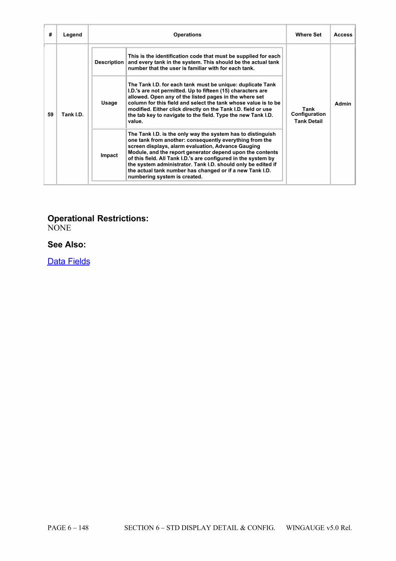
7/16/2019 3900 Manual
http://slidepdf.com/reader/full/3900-manual 196/266
PAGE 6 – 148 SECTION 6 – STD DISPLAY DETAIL & CONFIG. WINGAUGE v5.0 Rel.
# Legend Operations Where Set Access
59 Tank I.D.
Description This is the identification code that must be supplied for eachand every tank in the system. This should be the actual tanknumber that the user is familiar with for each tank.
Usage
The Tank I.D. for each tank must be unique: duplicate TankI.D.'s are not permitted. Up to fifteen (15) characters areallowed. Open any of the listed pages in the where setcolumn for this field and select the tank whose value is to be
modified. Either click directly on the Tank I.D. field or usethe tab key to navigate to the field. Type the new Tank I.D.value.
Impact
The Tank I.D. is the only way the system has to distinguishone tank from another: consequently everything from thescreen displays, alarm evaluation, Advance GaugingModule, and the report generator depend upon the contentsof this field. All Tank I.D.'s are configured in the system bythe system administrator. Tank I.D. should only be edited if the actual tank number has changed or if a new Tank I.D.numbering system is created.
TankConfiguration
Tank Detail
Admin
Operational Restrictions: NONE
See Also:
Data Fields
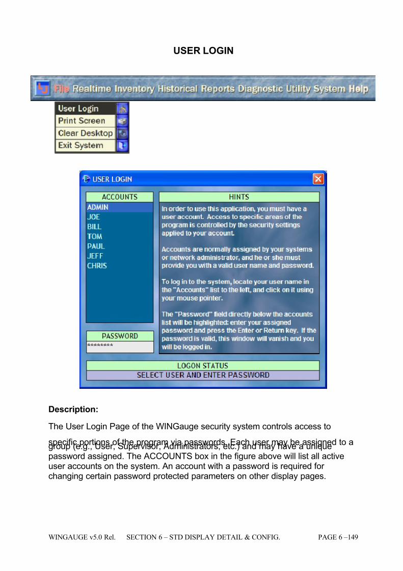
7/16/2019 3900 Manual
http://slidepdf.com/reader/full/3900-manual 197/266
WINGAUGE v5.0 Rel. SECTION 6 – STD DISPLAY DETAIL & CONFIG. PAGE 6 –149
USER LOGIN
Description:
The User Login Page of the WINGauge security system controls access to
specific portions of the program via passwords. Each user may be assigned to agroup (e.g., User, Supervisor, Administrators, etc.) and may have a uniquepassword assigned. The ACCOUNTS box in the figure above will list all activeuser accounts on the system. An account with a password is required for changing certain password protected parameters on other display pages.
7/16/2019 3900 Manual
http://slidepdf.com/reader/full/3900-manual 198/266
PAGE 6 – 150 SECTION 6 – STD DISPLAY DETAIL & CONFIG. WINGAUGE v5.0 Rel.
Operator Available Functions:
• Login: Logging in is as simple as clicking on an account name, thenclicking on inside the box below "password" and entering the proper password for the selected account. The LOGON STATUS box will reflectthe current state of the login process. After logging in, simply close thewindow (or press the Esc key) to return to WINGauge. The login windowshould disappear by itself after several seconds.
• Logout: logging OUT of the system is equally painless: simply click on theLogin icon again. The currently logged-in account will be logged off. Either log in with a new account or close the window.
Operational Restrictions:
Usage limited to existing user accounts and passwords.
See Also:
Security Page

7/16/2019 3900 Manual
http://slidepdf.com/reader/full/3900-manual 199/266
WINGAUGE v5.0 Rel. SECTION 6 – STD DISPLAY DETAIL & CONFIG. PAGE 6 –151
VOLUME & RATES
Description:
The Volumes & Rates page is just what it says it is: a view of the calculatedvolume and rate values for a single tank. Critical time is also shown. Becausethis is a Dynamic form, more than one copy of the form may be loaded
simultaneously. Loading two or more V&R pages and selecting different tanks isa good way to monitor the progress of multi-tank transfer operations.
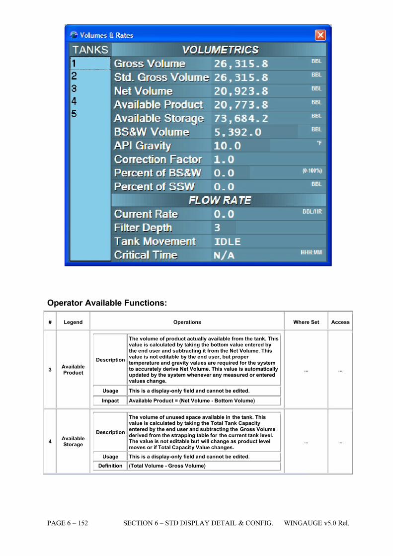
7/16/2019 3900 Manual
http://slidepdf.com/reader/full/3900-manual 200/266
PAGE 6 – 152 SECTION 6 – STD DISPLAY DETAIL & CONFIG. WINGAUGE v5.0 Rel.
Operator Available Functions:
# Legend Operations Where Set Access
3 AvailableProduct
Description
The volume of product actually available from the tank. Thisvalue is calculated by taking the bottom value entered bythe end user and subtracting it from the Net Volume. Thisvalue is not editable by the end user, but proper temperature and gravity values are required for the systemto accurately derive Net Volume. This value is automaticallyupdated by the system whenever any measured or enteredvalues change.
Usage This is a display-only field and cannot be edited.
Impact Available Product = (Net Volume - Bottom Volume)
... ...
4 AvailableStorage
Description
The volume of unused space available in the tank. Thisvalue is calculated by taking the Total Tank Capacityentered by the end user and subtracting the Gross Volumederived from the strapping table for the current tank level.The value is not editable but will change as product levelmoves or if Total Capacity Value changes.
Usage This is a display-only field and cannot be edited. Definition (Total Volume - Gross Volume)
... ...
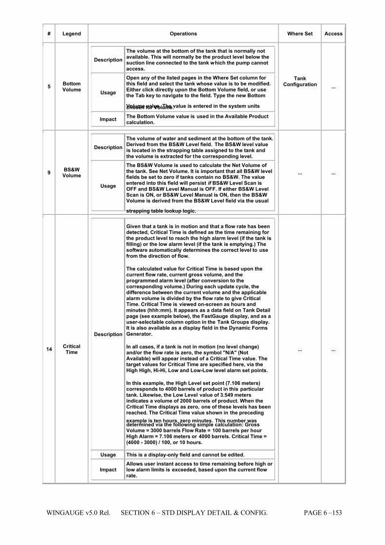
7/16/2019 3900 Manual
http://slidepdf.com/reader/full/3900-manual 201/266
WINGAUGE v5.0 Rel. SECTION 6 – STD DISPLAY DETAIL & CONFIG. PAGE 6 –153
# Legend Operations Where Set Access
5 BottomVolume
Description The volume at the bottom of the tank that is normally notavailable. This will normally be the product level below thesuction line connected to the tank which the pump cannotaccess.
Usage
Open any of the listed pages in the Where Set column for this field and select the tank whose value is to be modified.Either click directly upon the Bottom Volume field, or usethe Tab key to navigate to the field. Type the new Bottom
Volume value. The value is entered in the system unitschosen for Volume.
Impact The Bottom Volume value is used in the Available Productcalculation.
TankConfiguration ...
9 BS&WVolume
Description The volume of water and sediment at the bottom of the tank.Derived from the BS&W Level field. The BS&W level valueis located in the strapping table assigned to the tank andthe volume is extracted for the corresponding level.
Usage
The BS&W Volume is used to calculate the Net Volume of the tank. See Net Volume. It is important that all BS&W levelfields be set to zero if tanks contain no BS&W. The valueentered into this field will persist if BS&W Level Scan isOFF and BS&W Level Manual is OFF. If either BS&W LevelScan is ON, or BS&W Level Manual is ON, then the BS&WVolume is derived from the BS&W Level field via the usual
strapping table lookup logic.
... ...
14 CriticalTime
Description
Given that a tank is in motion and that a flow rate has beendetected, Critical Time is defined as the time remaining for the product level to reach the high alarm level (if the tank isfilling) or the low alarm level (if the tank is emptying.) Thesoftware automatically determines the correct level to usefrom the direction of flow.
The calculated value for Critical Time is based upon thecurrent flow rate, current gross volume, and theprogrammed alarm level (after conversion to thecorresponding volume.) During each update cycle, thedifference between the current volume and the applicablealarm volume is divided by the flow rate to give CriticalTime. Critical Time is viewed on-screen as hours andminutes (hhh:mm). It appears as a data field on Tank Detailpage (see example below), the FastGauge display, and as auser-selectable column option in the Tank Groups display.It is also available as a display field in the Dynamic Forms
Generator.
In all cases, if a tank is not in motion (no level change)and/or the flow rate is zero, the symbol "N/A" (NotAvailable) will appear instead of a Critical Time value. Thetarget values for Critical Time are specified here, via theHigh High, Hi-Hi, Low and Low-Low level alarm set points.
In this example, the High Level set point (7.106 meters)corresponds to 4000 barrels of product in this particular tank. Likewise, the Low Level value of 3.549 metersindicates a volume of 2000 barrels of product. When theCritical Time displays as zero, one of these levels has beenreached. The Critical Time value shown in the preceding
example is ten hours, zero minutes. This number wasdetermined via the following simple calculation: GrossVolume = 3000 barrels Flow Rate = 100 barrels per hour High Alarm = 7.106 meters or 4000 barrels. Critical Time =(4000 - 3000) / 100, or 10 hours.
Usage This is a display-only field and cannot be edited.
Impact Allows user instant access to time remaining before high or low alarm limits is exceeded, based upon the current flowrate.
... ...
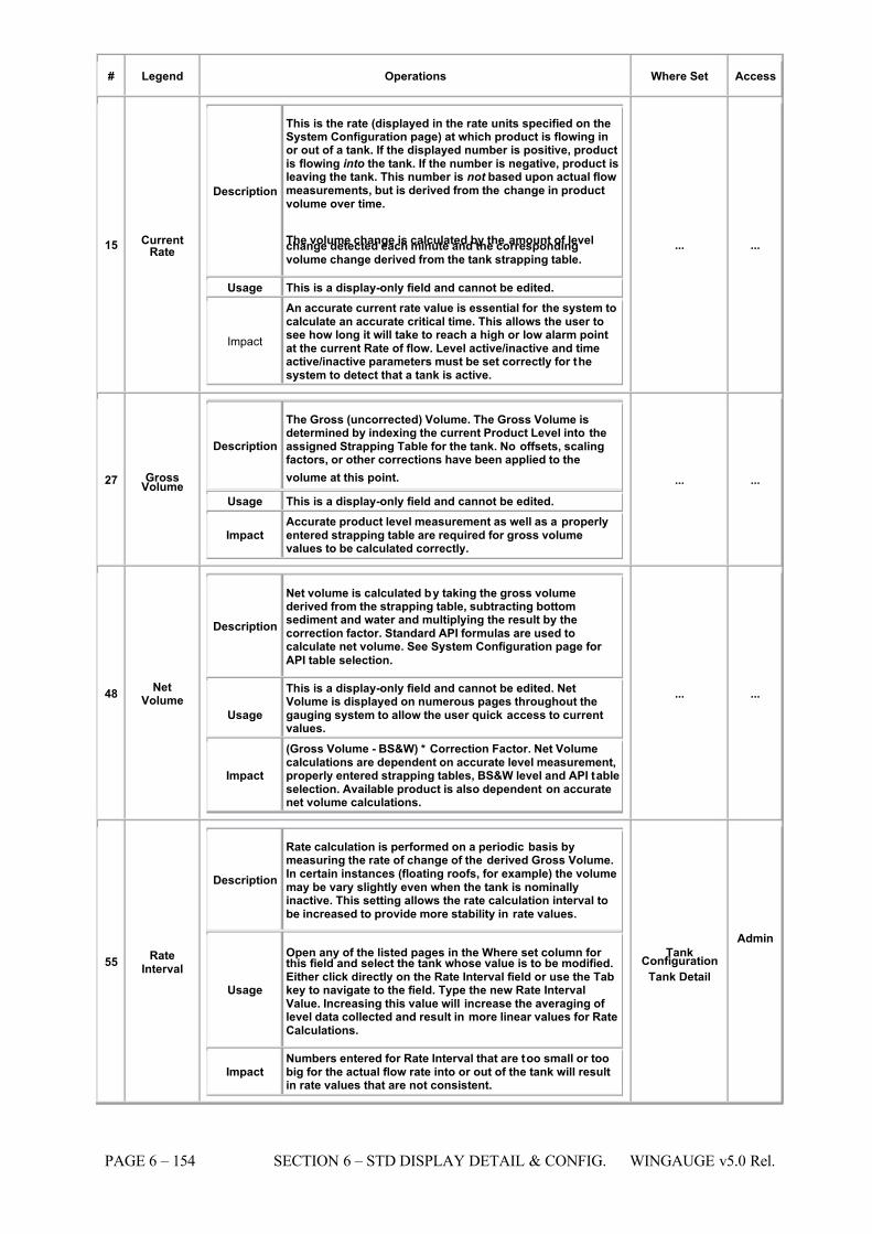
7/16/2019 3900 Manual
http://slidepdf.com/reader/full/3900-manual 202/266
PAGE 6 – 154 SECTION 6 – STD DISPLAY DETAIL & CONFIG. WINGAUGE v5.0 Rel.
# Legend Operations Where Set Access
15 CurrentRate
Description
This is the rate (displayed in the rate units specified on theSystem Configuration page) at which product is flowing inor out of a tank. If the displayed number is positive, productis flowing into the tank. If the number is negative, product isleaving the tank. This number is not based upon actual flowmeasurements, but is derived from the change in productvolume over time.
The volume change is calculated by the amount of levelchange detected each minute and the correspondingvolume change derived from the tank strapping table.
Usage This is a display-only field and cannot be edited.
Impact
An accurate current rate value is essential for the system tocalculate an accurate critical time. This allows the user tosee how long it will take to reach a high or low alarm pointat the current Rate of flow. Level active/inactive and timeactive/inactive parameters must be set correctly for thesystem to detect that a tank is active.
... ...
27 GrossVolume
Description
The Gross (uncorrected) Volume. The Gross Volume isdetermined by indexing the current Product Level into theassigned Strapping Table for the tank. No offsets, scalingfactors, or other corrections have been applied to the
volume at this point. Usage This is a display-only field and cannot be edited.
ImpactAccurate product level measurement as well as a properlyentered strapping table are required for gross volumevalues to be calculated correctly.
... ...
48 NetVolume
Description
Net volume is calculated by taking the gross volumederived from the strapping table, subtracting bottomsediment and water and multiplying the result by thecorrection factor. Standard API formulas are used tocalculate net volume. See System Configuration page for
API table selection.
Usage
This is a display-only field and cannot be edited. NetVolume is displayed on numerous pages throughout thegauging system to allow the user quick access to currentvalues.
Impact
(Gross Volume - BS&W) * Correction Factor. Net Volumecalculations are dependent on accurate level measurement,properly entered strapping tables, BS&W level and API tableselection. Available product is also dependent on accuratenet volume calculations.
... ...
55 RateInterval
Description
Rate calculation is performed on a periodic basis bymeasuring the rate of change of the derived Gross Volume.In certain instances (floating roofs, for example) the volumemay be vary slightly even when the tank is nominallyinactive. This setting allows the rate calculation interval tobe increased to provide more stability in rate values.
Usage
Open any of the listed pages in the Where set column for this field and select the tank whose value is to be modified.Either click directly on the Rate Interval field or use the Tabkey to navigate to the field. Type the new Rate IntervalValue. Increasing this value will increase the averaging of level data collected and result in more linear values for RateCalculations.
Impact Numbers entered for Rate Interval that are too small or toobig for the actual flow rate into or out of the tank will resultin rate values that are not consistent.
TankConfiguration
Tank Detail
Admin
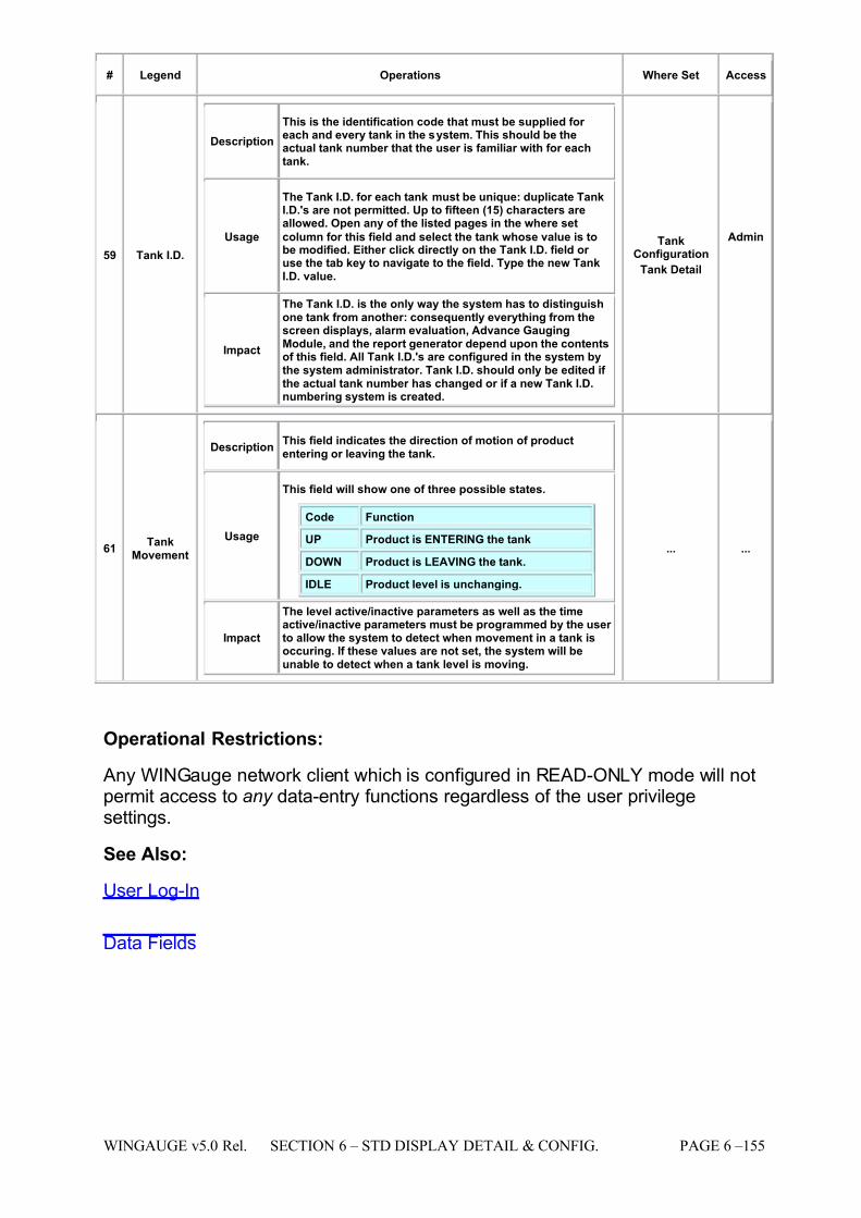
7/16/2019 3900 Manual
http://slidepdf.com/reader/full/3900-manual 203/266
WINGAUGE v5.0 Rel. SECTION 6 – STD DISPLAY DETAIL & CONFIG. PAGE 6 –155
# Legend Operations Where Set Access
59 Tank I.D.
Description This is the identification code that must be supplied for each and every tank in the system. This should be theactual tank number that the user is familiar with for eachtank.
Usage
The Tank I.D. for each tank must be unique: duplicate TankI.D.'s are not permitted. Up to fifteen (15) characters areallowed. Open any of the listed pages in the where set
column for this field and select the tank whose value is tobe modified. Either click directly on the Tank I.D. field or use the tab key to navigate to the field. Type the new TankI.D. value.
Impact
The Tank I.D. is the only way the system has to distinguishone tank from another: consequently everything from thescreen displays, alarm evaluation, Advance GaugingModule, and the report generator depend upon the contentsof this field. All Tank I.D.'s are configured in the system bythe system administrator. Tank I.D. should only be edited if the actual tank number has changed or if a new Tank I.D.numbering system is created.
TankConfiguration
Tank Detail
Admin
61 TankMovement
Description This field indicates the direction of motion of productentering or leaving the tank.
Usage
This field will show one of three possible states.
Code Function
UP Product is ENTERING the tank
DOWN Product is LEAVING the tank.
IDLE Product level is unchanging.
Impact
The level active/inactive parameters as well as the timeactive/inactive parameters must be programmed by the user to allow the system to detect when movement in a tank isoccuring. If these values are not set, the system will beunable to detect when a tank level is moving.
... ...
Operational Restrictions:
Any WINGauge network client which is configured in READ-ONLY mode will notpermit access to any data-entry functions regardless of the user privilegesettings.
See Also:
User Log-In
Data Fields
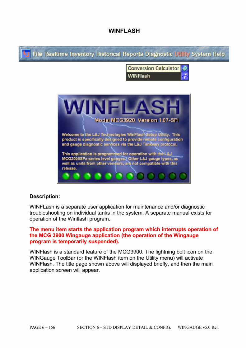
7/16/2019 3900 Manual
http://slidepdf.com/reader/full/3900-manual 204/266
PAGE 6 – 156 SECTION 6 – STD DISPLAY DETAIL & CONFIG. WINGAUGE v5.0 Rel.
WINFLASH
Description:
WINFLash is a separate user application for maintenance and/or diagnostictroubleshooting on individual tanks in the system. A separate manual exists for operation of the Winflash program.
The menu item starts the application program which interrupts operation of the MCG 3900 Wingauge application (the operation of the Wingaugeprogram is temporarily suspended).
WINFlash is a standard feature of the MCG3900. The lightning bolt icon on theWINGauge ToolBar (or the WINFlash item on the Utility menu) will activateWINFlash. The title page shown above will displayed briefly, and then the mainapplication screen will appear.
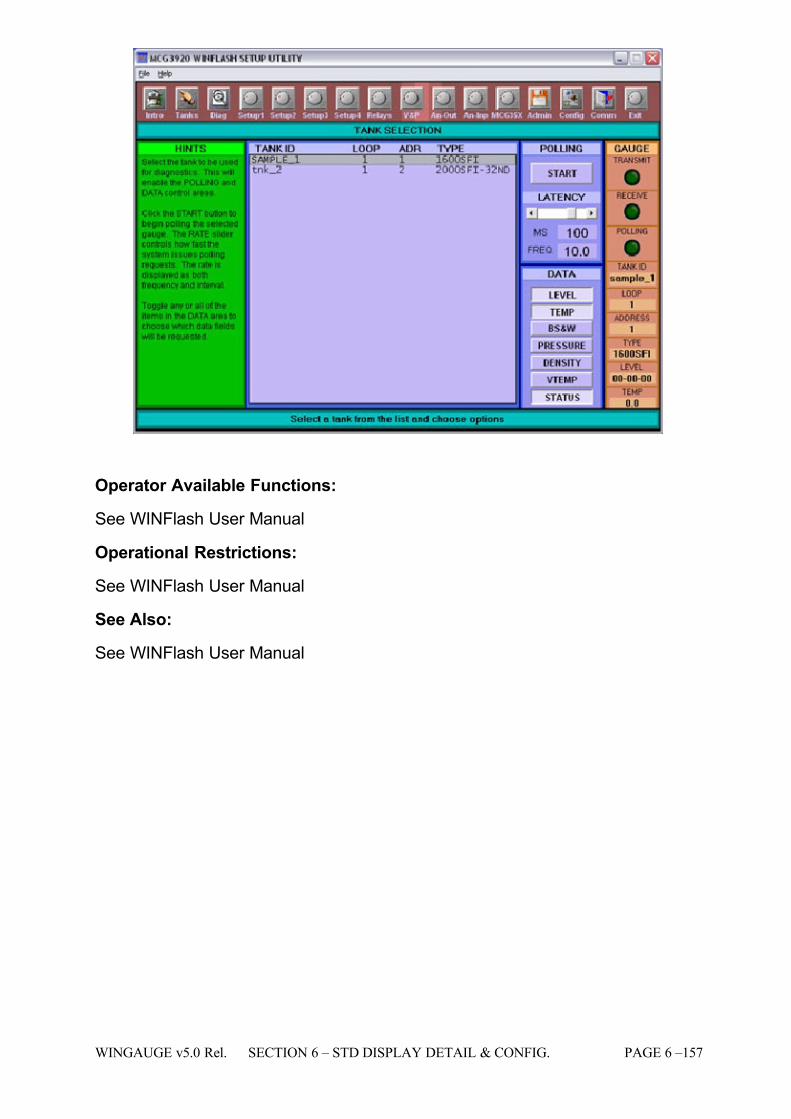
7/16/2019 3900 Manual
http://slidepdf.com/reader/full/3900-manual 205/266
WINGAUGE v5.0 Rel. SECTION 6 – STD DISPLAY DETAIL & CONFIG. PAGE 6 –157
Operator Available Functions:
See WINFlash User Manual
Operational Restrictions:
See WINFlash User Manual
See Also:
See WINFlash User Manual

7/16/2019 3900 Manual
http://slidepdf.com/reader/full/3900-manual 206/266
PAGE 6 – 158 SECTION 6 – STD DISPLAY DETAIL & CONFIG. WINGAUGE v5.0 Rel.

7/16/2019 3900 Manual
http://slidepdf.com/reader/full/3900-manual 207/266
WINGAUGE v5.0 Rel. SECTION 7 – PRINTED REPORTS PAGE 7 –1
SECTION 7
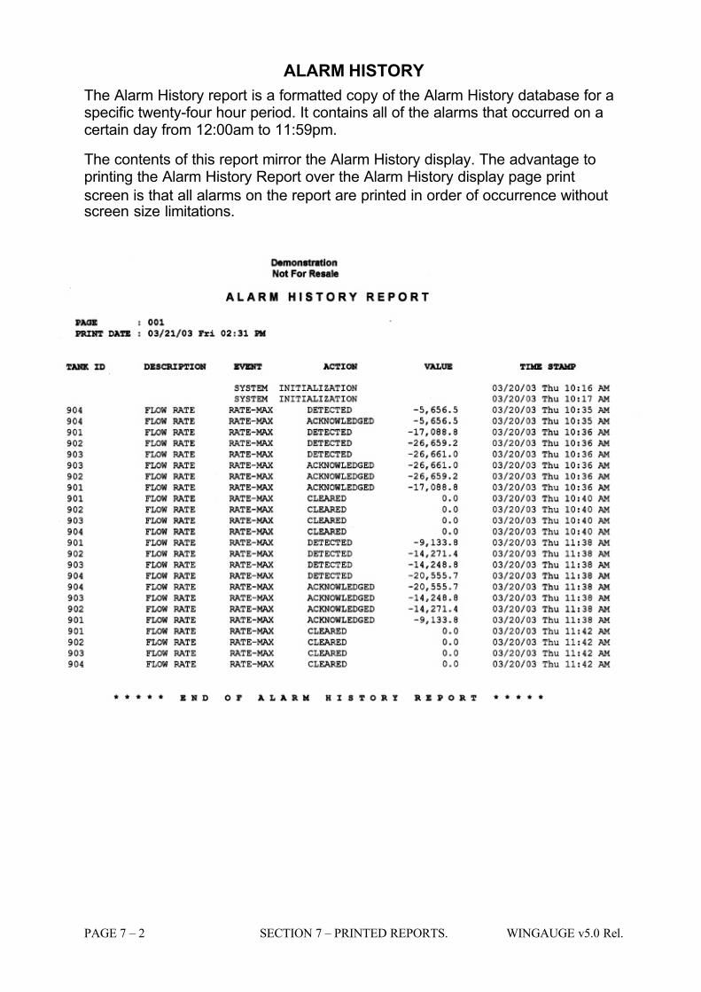
7/16/2019 3900 Manual
http://slidepdf.com/reader/full/3900-manual 208/266
PAGE 7 – 2 SECTION 7 – PRINTED REPORTS. WINGAUGE v5.0 Rel.
ALARM HISTORY
The Alarm History report is a formatted copy of the Alarm History database for aspecific twenty-four hour period. It contains all of the alarms that occurred on acertain day from 12:00am to 11:59pm.
The contents of this report mirror the Alarm History display. The advantage toprinting the Alarm History Report over the Alarm History display page print
screen is that all alarms on the report are printed in order of occurrence withoutscreen size limitations.
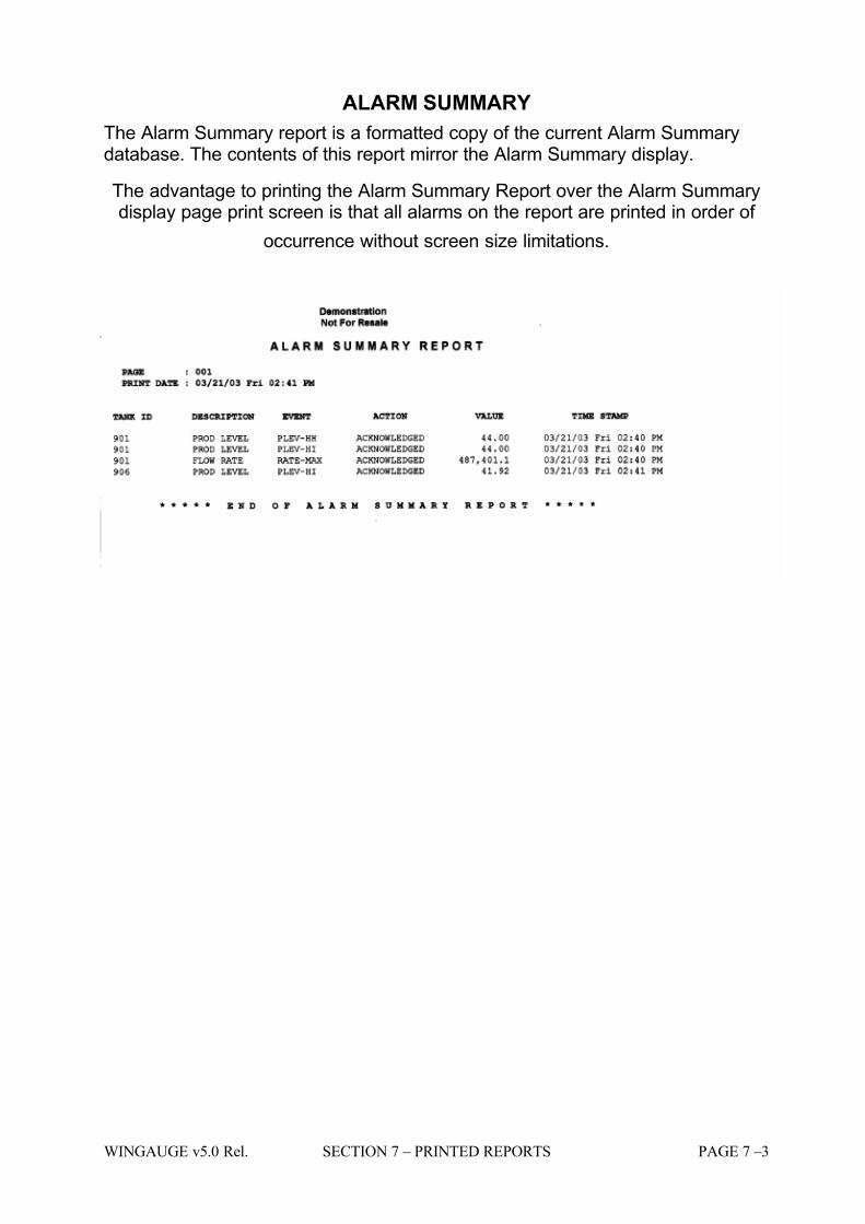
7/16/2019 3900 Manual
http://slidepdf.com/reader/full/3900-manual 209/266
WINGAUGE v5.0 Rel. SECTION 7 – PRINTED REPORTS PAGE 7 –3
ALARM SUMMARY
The Alarm Summary report is a formatted copy of the current Alarm Summarydatabase. The contents of this report mirror the Alarm Summary display.
The advantage to printing the Alarm Summary Report over the Alarm Summarydisplay page print screen is that all alarms on the report are printed in order of
occurrence without screen size limitations.
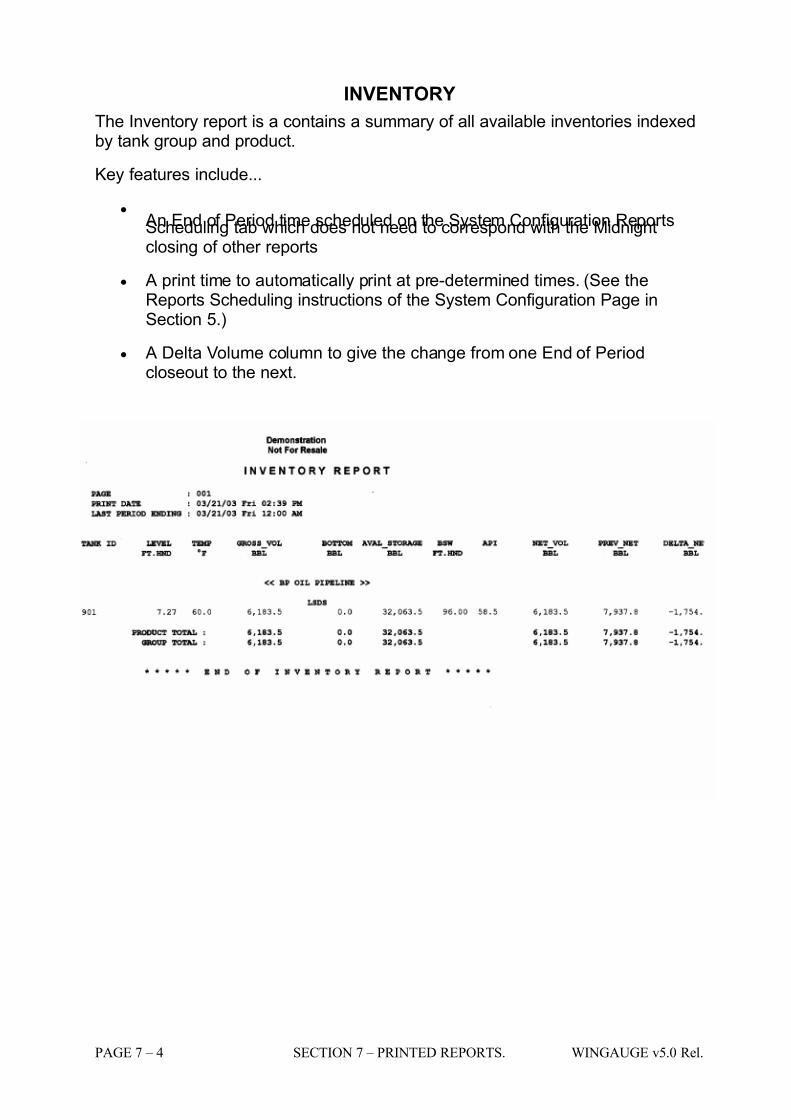
7/16/2019 3900 Manual
http://slidepdf.com/reader/full/3900-manual 210/266
PAGE 7 – 4 SECTION 7 – PRINTED REPORTS. WINGAUGE v5.0 Rel.
INVENTORY
The Inventory report is a contains a summary of all available inventories indexedby tank group and product.
Key features include...
•
An End of Period time scheduled on the System Configuration ReportsScheduling tab which does not need to correspond with the Midnightclosing of other reports
• A print time to automatically print at pre-determined times. (See theReports Scheduling instructions of the System Configuration Page inSection 5.)
• A Delta Volume column to give the change from one End of Periodcloseout to the next.
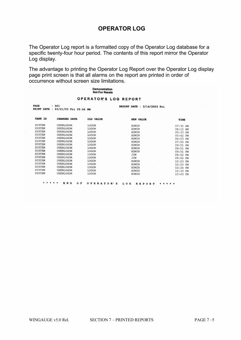
7/16/2019 3900 Manual
http://slidepdf.com/reader/full/3900-manual 211/266
WINGAUGE v5.0 Rel. SECTION 7 – PRINTED REPORTS PAGE 7 –5
OPERATOR LOG
The Operator Log report is a formatted copy of the Operator Log database for aspecific twenty-four hour period. The contents of this report mirror the Operator Log display.
The advantage to printing the Operator Log Report over the Operator Log displaypage print screen is that all alarms on the report are printed in order of occurrence without screen size limitations.
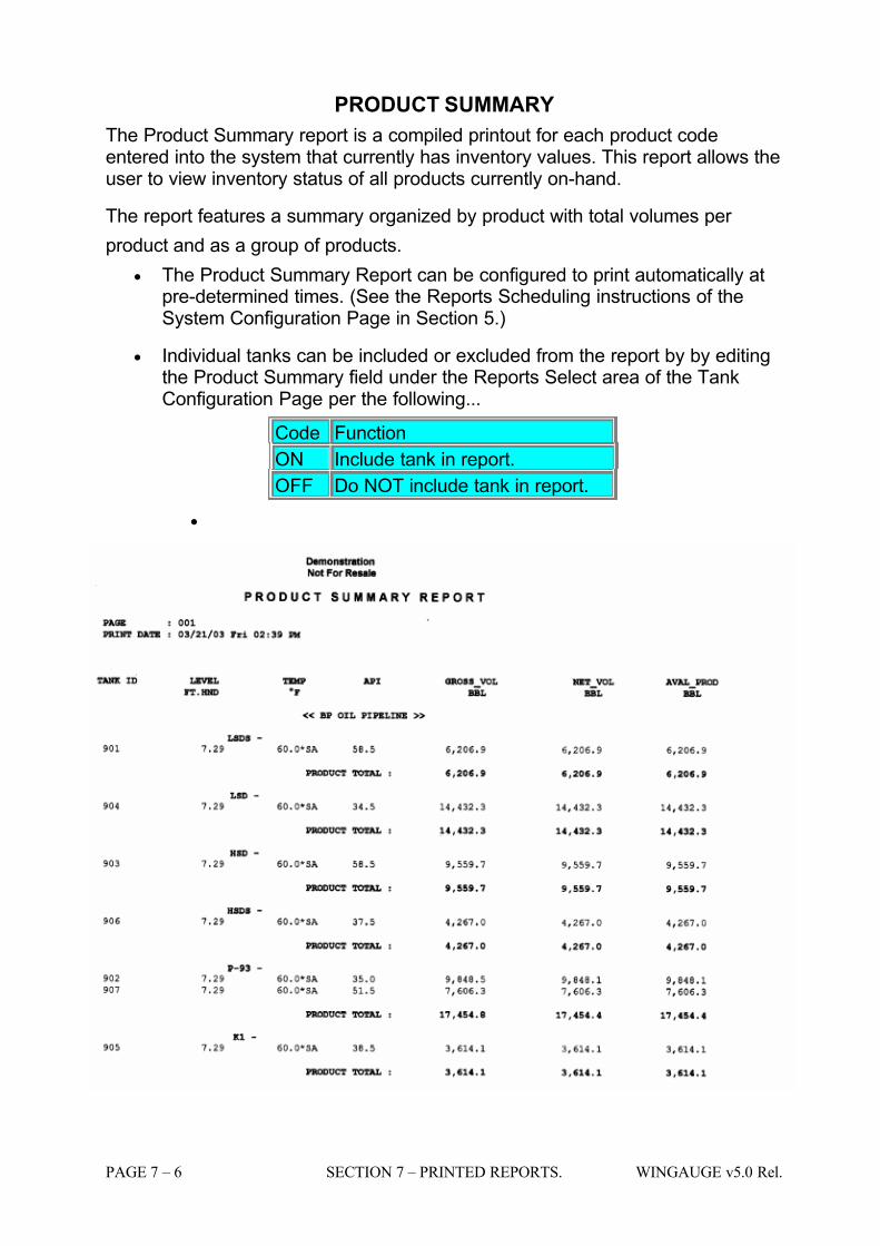
7/16/2019 3900 Manual
http://slidepdf.com/reader/full/3900-manual 212/266
PAGE 7 – 6 SECTION 7 – PRINTED REPORTS. WINGAUGE v5.0 Rel.
PRODUCT SUMMARY
The Product Summary report is a compiled printout for each product codeentered into the system that currently has inventory values. This report allows theuser to view inventory status of all products currently on-hand.
The report features a summary organized by product with total volumes per
product and as a group of products.
• The Product Summary Report can be configured to print automatically atpre-determined times. (See the Reports Scheduling instructions of theSystem Configuration Page in Section 5.)
• Individual tanks can be included or excluded from the report by by editingthe Product Summary field under the Reports Select area of the TankConfiguration Page per the following...
Code Function
ON Include tank in report.
OFF Do NOT include tank in report.
•
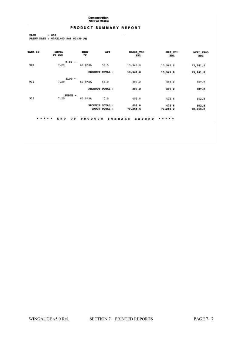
7/16/2019 3900 Manual
http://slidepdf.com/reader/full/3900-manual 213/266
WINGAUGE v5.0 Rel. SECTION 7 – PRINTED REPORTS PAGE 7 –7
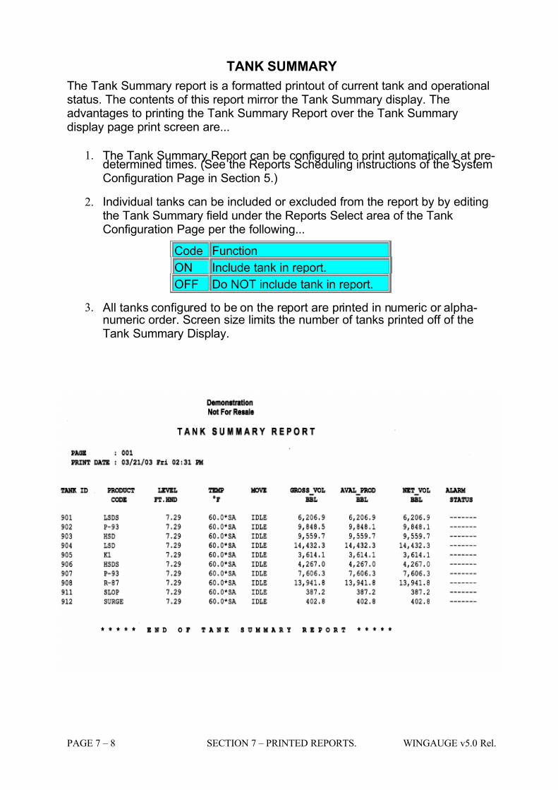
7/16/2019 3900 Manual
http://slidepdf.com/reader/full/3900-manual 214/266
PAGE 7 – 8 SECTION 7 – PRINTED REPORTS. WINGAUGE v5.0 Rel.
TANK SUMMARY
The Tank Summary report is a formatted printout of current tank and operationalstatus. The contents of this report mirror the Tank Summary display. Theadvantages to printing the Tank Summary Report over the Tank Summarydisplay page print screen are...
1. The Tank Summary Report can be configured to print automatically at pre-determined times. (See the Reports Scheduling instructions of the SystemConfiguration Page in Section 5.)
2. Individual tanks can be included or excluded from the report by by editingthe Tank Summary field under the Reports Select area of the TankConfiguration Page per the following...
Code Function
ON Include tank in report.
OFF Do NOT include tank in report.
3. All tanks configured to be on the report are printed in numeric or alpha-numeric order. Screen size limits the number of tanks printed off of theTank Summary Display.

7/16/2019 3900 Manual
http://slidepdf.com/reader/full/3900-manual 215/266
WINGAUGE v5.0 Rel. SECTION 8 – HELP PAGE 8 –1
SECTION 8
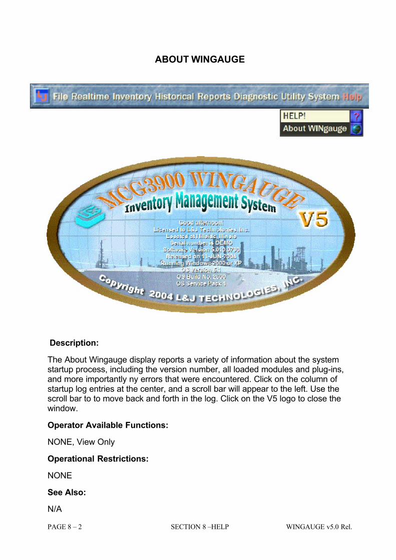
7/16/2019 3900 Manual
http://slidepdf.com/reader/full/3900-manual 216/266
PAGE 8 – 2 SECTION 8 –HELP WINGAUGE v5.0 Rel.
ABOUT WINGAUGE
Description:
The About Wingauge display reports a variety of information about the systemstartup process, including the version number, all loaded modules and plug-ins,and more importantly ny errors that were encountered. Click on the column of startup log entries at the center, and a scroll bar will appear to the left. Use thescroll bar to to move back and forth in the log. Click on the V5 logo to close thewindow.
Operator Available Functions:
NONE, View Only
Operational Restrictions:
NONE
See Also:
N/A
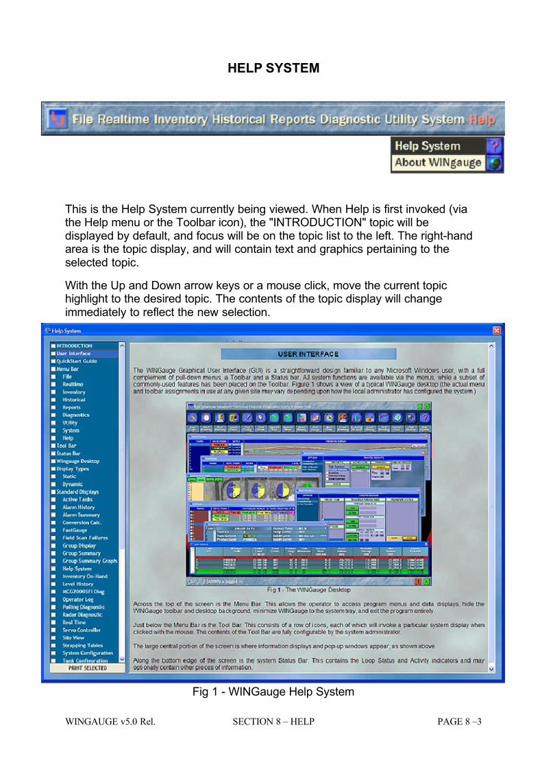
7/16/2019 3900 Manual
http://slidepdf.com/reader/full/3900-manual 217/266
WINGAUGE v5.0 Rel. SECTION 8 – HELP PAGE 8 –3
HELP SYSTEM
This is the Help System currently being viewed. When Help is first invoked (viathe Help menu or the Toolbar icon), the "INTRODUCTION" topic will bedisplayed by default, and focus will be on the topic list to the left. The right-handarea is the topic display, and will contain text and graphics pertaining to theselected topic.
With the Up and Down arrow keys or a mouse click, move the current topichighlight to the desired topic. The contents of the topic display will changeimmediately to reflect the new selection.
Fig 1 - WINGauge Help System

7/16/2019 3900 Manual
http://slidepdf.com/reader/full/3900-manual 218/266
PAGE 8 – 4 SECTION 8 –HELP WINGAUGE v5.0 Rel.
Additional help in the form of pop-up tooltips are available for all fields on Flow-style Dynamic Forms.. Simply hold the mouse over the field legend (e.g., ProductLevel, Total Capacity, etc.) for a few seconds and a one-line description of thefield will appear. Moving the mouse will make the tooltip disappear again.

7/16/2019 3900 Manual
http://slidepdf.com/reader/full/3900-manual 219/266
WINGAUGE v5.0 Rel. SECTION 8 – HELP PAGE 8 –5
SUPPORT
Sales, Service & Technical Support for all L&J Technologies products.
L&J Technologies, Inc.
5911 Butterfield Road
Hillside, Illinois 60162
(708) 236-6000
(708) 236-6006 Fax

7/16/2019 3900 Manual
http://slidepdf.com/reader/full/3900-manual 220/266
PAGE 8 – 6 SECTION 8 –HELP WINGAUGE v5.0 Rel.

7/16/2019 3900 Manual
http://slidepdf.com/reader/full/3900-manual 221/266
WINGAUGE v5.0 Rel. SECTION 9 – SYSTEM DATA FIELDS PAGE 9 –1
SECTION 9
7/16/2019 3900 Manual
http://slidepdf.com/reader/full/3900-manual 222/266
PAGE 9 – 2 SECTION 9 –SYSTEM DATA FIELDS WINGAUGE v5.0 Rel.
SYSTEM DATA FIELDS
INTRODUCTION
WINGauge processes some sixty-odd numeric and textual data fields, some of which are supplied by the end user, andothers that are entirely computer-generated. This section documents, in some detail, the workings of these various fieldsand how they interact with each other.
On-screen access to the various user-modifiable data fields is controlled by the WINGauge security system. By default,WINGauge ships with three different user groups: Administrator, Supervisor and Operator. Users assigned to each of thesethree groups typically have differing access privileges. This means that an individual assigned to the Operator group, for
example, may not be able to modify the contents of data fields that a Supervisor or an Administrator could. The last columnon the right, Access, describes the minimum security level required to modify the corresponding data field. This is intendedto protect against unintentional or unauthorized modification of system configuration data. Actual assignment of individualusers to specific groups is the customer's responsibility.
CAVEATS
Fields which are read-only (i.e., not modifiable by the user under any conditions) are marked with a circumflex, "...".
All numeric quantities (e.g., Level, Temperature, Volume and so forth) are assumed to be displayed using the appropriatemeasurement units selected on the System Configuration page, unless otherwise noted. The Usage sections of eachdescription also assume that a user with an appropriate security level has already logged in: if this is not the case, anyattempt to modify a data field will fail, and will immediately bring up the User Login screen.
There is no explicit "save" function. All authorized modifications to data fields are immediately and automatically saved by
the system.
The user groups referenced in the Access column refer to the default shipping configuration of WINGauge: the local systemAdministrator may create additional groups.
ALARM CLASSES
The MCG3900 has three (3) alarm categories or classes. Each class is distinguished by a different sound that is generatedwhen the alarm occurs: this capability is only available to multimedia-equipped computer systems with attached speakers.Systems using the relay alarm output of the MCG3281 Slimline FIC, for example, only have a single control output and thuseffectively only have a single alarm class.
The three classes are organized by increasing severity, as shown below:
Class Description Used ByOperational Non-critical utility alarm.. Float Alarm
Warning Non-critical warning alarm. Flow Rate, High Level, Low Level Emergency Critical alarm! HiHi Level, LoLo Level, Dead Tank, Discrete Inputs (incl. MCG3281)
Operational and Warning alarms are generally non-critical, but do indicate a condition for which the system was specificallyinstructed to monitor. The Emergency alarms indicate that a critical malfunction or other condition has or is about to occur,and that remedial action should be taken IMMEDIATELY!
IMPORTANT
The appropriateness of generated alarms is entirely dependent upon system configuration values entered by the customer.If, for example, a HiHi Alarm Level were entered that was above a tank's actual safe fill level, a tank overflow condition couldoccur, and no alarms would be generated.
In addition, alarms will only occur if both field scan and alarm evaluation are enabled for the quantity being monitored. For example, in order for a temperature alarm to be generated, the Tank Control field must have both the (S)can and (A)larmEvaluation bulbs lit and the Temp Control field must also have them lit. If a manual level has been entered for Temperature,the system will evaluate the manual value not the field value!
7/16/2019 3900 Manual
http://slidepdf.com/reader/full/3900-manual 223/266
WINGAUGE v5.0 Rel. SECTION 9 – SYSTEM DATA FIELDS PAGE 9 –3
DATA FIELDS
The following table describes all of the numeric and textual data items that are used throughout the WINGauge gaugingsystem. The Legend column references the text used to refer to each field on the various WINGauge screens. The Operations column provides detailed information on the content of each data field, how it is used, and how it interacts with related datafields. Where Set indicates the pages where the field can be modified.
STANDARD DATA FIELDS
# Legend Operations Where Set Access
1 APIGravity
Description
Gravity (weight per unit of volume) of crude oil or other liquid hydrocarbons as measured by a systemrecommended by the American Petroleum Institute.Simply enter a value into this field and the system willautomatically begin to calculate volumes based uponthe new entry. Valid API values range from -37 to 340.
Usage
Open any of the listed pages in the Where Set columnfor this field and select the tank whose value is to bemodified. Either click directly upon the API Gravityfield, or use the Tab key to navigate to the field. Typethe new API Gravity value.
Impact
The entered API Gravity affects the calculated APIcorrection factor, which in turn affects the derivedNet Volume value and available product values.
NOTE: If you do not have a valid remote temperaturevalue, and/or have not entered a manual temperature,the system will automatically set the internalcorrection factor to 1 regardless of the API Tablesetting or the displayed API value. This effectivelyreferences the system to 60 degrees Fahrenheit,which is standard for most API calculations.
See the Temp Control and the Product Temp fielddescriptions below for more information on setting amanual temperature, and the behavior of the producttemperature display field under fault conditions.
Tank Configuration
Tank Detail
Admin
Super
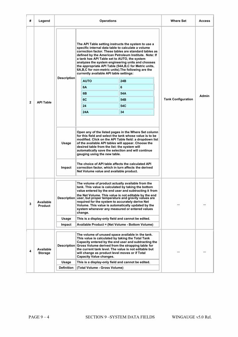
7/16/2019 3900 Manual
http://slidepdf.com/reader/full/3900-manual 224/266
PAGE 9 – 4 SECTION 9 –SYSTEM DATA FIELDS WINGAUGE v5.0 Rel.
# Legend Operations Where Set Access
2 API Table
Description
The API Table setting instructs the system to use aspecific internal data table to calculate a volumecorrection factor. These tables are standard tables asdefined by the American Petroleum Institute. Note: If a tank has API Table set to AUTO, the systemanalyzes the system engineering units and choosesthe appropriate API Table (54A,B,C for Metric units,6A,B,C for non-metric units).The following are thecurrently available API table settings:
AUTO 24B
6A 6
6B 54A
6C 54B
24 54C
24A 34
Usage
Open any of the listed pages in the Where Set columnfor this field and select the tank whose value is to bemodified. Click on the API Table field: a dropdown listof the available API tables will appear. Choose thedesired table from the list: the system willautomatically save the selection and will continuegauging using the new table.
Impact The choice of API table affects the calculated APIcorrection factor, which in turn affects the derived
Net Volume value and available product.
Tank Configuration Admin
3 AvailableProduct
Description
The volume of product actually available from thetank. This value is calculated by taking the bottomvalue entered by the end user and subtracting it from
the Net Volume. This value is not editable by the enduser, but proper temperature and gravity values arerequired for the system to accurately derive NetVolume. This value is automatically updated by thesystem whenever any measured or entered valueschange.
Usage This is a display-only field and cannot be edited.
Impact Available Product = (Net Volume - Bottom Volume)
... ...
4 AvailableStorage
Description
The volume of unused space available in the tank.This value is calculated by taking the Total TankCapacity entered by the end user and subtracting theGross Volume derived from the strapping table for the current tank level. The value is not editable butwill change as product level moves or if TotalCapacity Value changes.
Usage This is a display-only field and cannot be edited. Definition (Total Volume - Gross Volume)
... ...
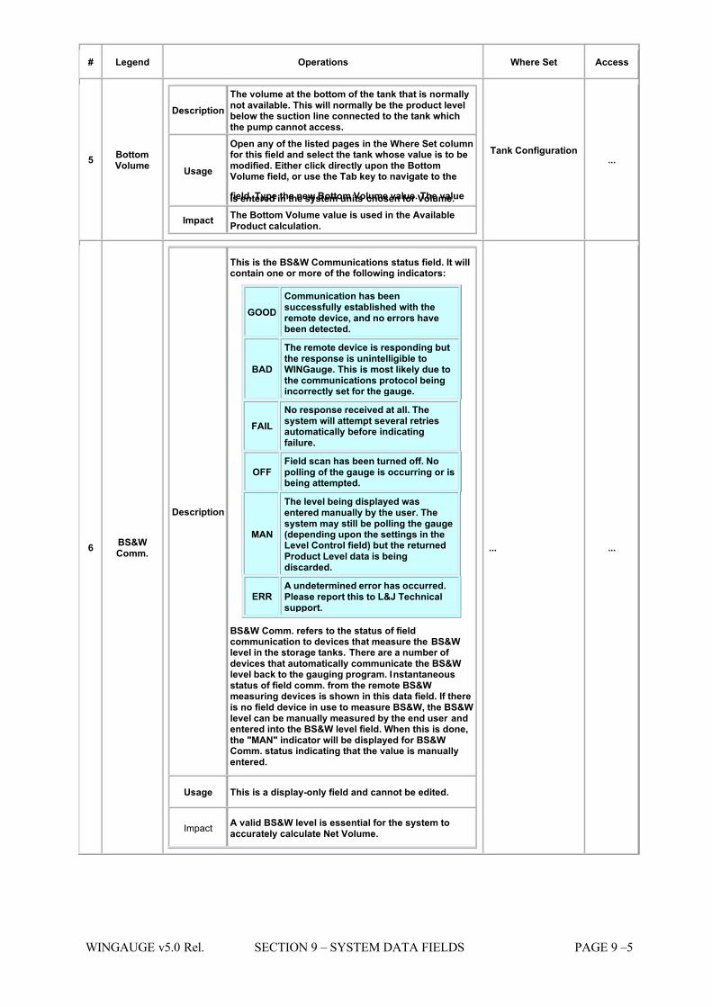
7/16/2019 3900 Manual
http://slidepdf.com/reader/full/3900-manual 225/266
WINGAUGE v5.0 Rel. SECTION 9 – SYSTEM DATA FIELDS PAGE 9 –5
# Legend Operations Where Set Access
5 BottomVolume
Description The volume at the bottom of the tank that is normallynot available. This will normally be the product levelbelow the suction line connected to the tank whichthe pump cannot access.
Usage
Open any of the listed pages in the Where Set columnfor this field and select the tank whose value is to bemodified. Either click directly upon the BottomVolume field, or use the Tab key to navigate to the
field. Type the new Bottom Volume value. The valueis entered in the system units chosen for Volume.
Impact The Bottom Volume value is used in the AvailableProduct calculation.
Tank Configuration ...
6 BS&WComm.
Description
This is the BS&W Communications status field. It willcontain one or more of the following indicators:
GOOD Communication has beensuccessfully established with theremote device, and no errors havebeen detected.
BAD
The remote device is responding butthe response is unintelligible toWINGauge. This is most likely due tothe communications protocol beingincorrectly set for the gauge.
FAIL No response received at all. Thesystem will attempt several retriesautomatically before indicatingfailure.
OFF Field scan has been turned off. Nopolling of the gauge is occurring or isbeing attempted.
MAN
The level being displayed wasentered manually by the user. Thesystem may still be polling the gauge(depending upon the settings in theLevel Control field) but the returnedProduct Level data is beingdiscarded.
ERR A undetermined error has occurred.Please report this to L&J Technicalsupport.
BS&W Comm. refers to the status of fieldcommunication to devices that measure the BS&Wlevel in the storage tanks. There are a number of devices that automatically communicate the BS&Wlevel back to the gauging program. Instantaneousstatus of field comm. from the remote BS&Wmeasuring devices is shown in this data field. If thereis no field device in use to measure BS&W, the BS&Wlevel can be manually measured by the end user andentered into the BS&W level field. When this is done,the "MAN" indicator will be displayed for BS&WComm. status indicating that the value is manuallyentered.
Usage This is a display-only field and cannot be edited.
ImpactA valid BS&W level is essential for the system toaccurately calculate Net Volume.
... ...
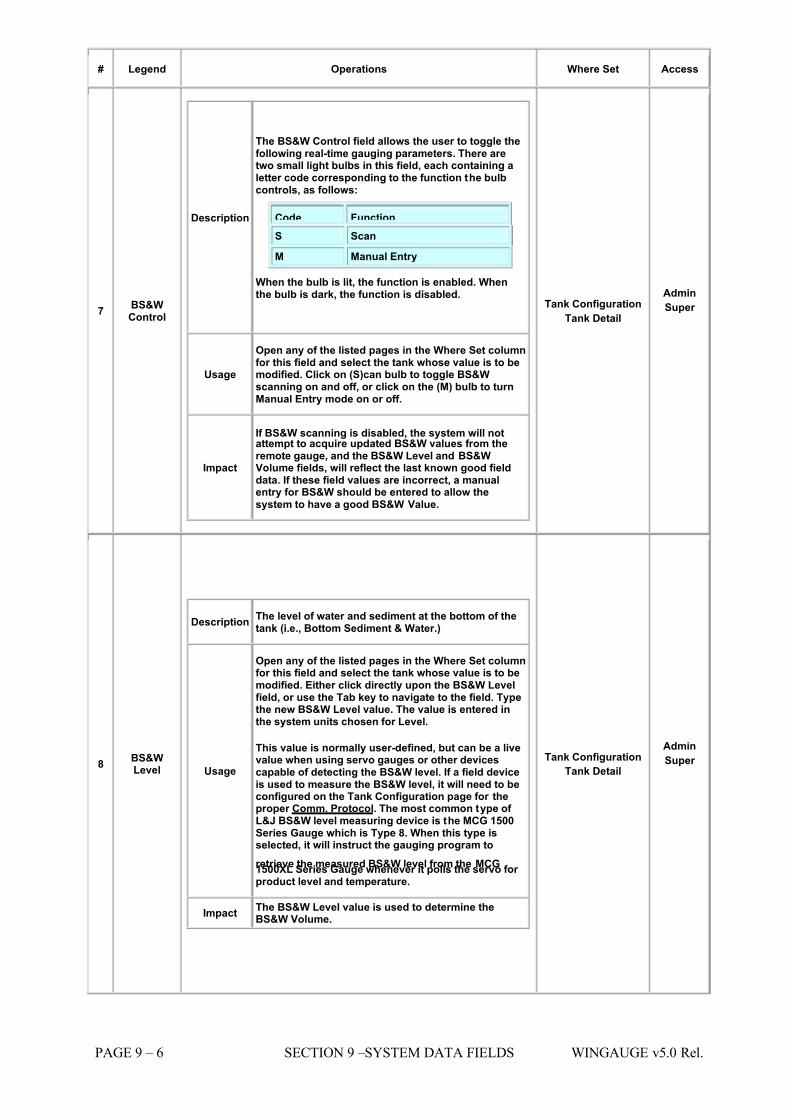
7/16/2019 3900 Manual
http://slidepdf.com/reader/full/3900-manual 226/266
PAGE 9 – 6 SECTION 9 –SYSTEM DATA FIELDS WINGAUGE v5.0 Rel.
# Legend Operations Where Set Access
7 BS&WControl
Description
The BS&W Control field allows the user to toggle thefollowing real-time gauging parameters. There aretwo small light bulbs in this field, each containing aletter code corresponding to the function the bulbcontrols, as follows:
Code Function S Scan
M Manual Entry
When the bulb is lit, the function is enabled. Whenthe bulb is dark, the function is disabled.
Usage
Open any of the listed pages in the Where Set columnfor this field and select the tank whose value is to bemodified. Click on (S)can bulb to toggle BS&Wscanning on and off, or click on the (M) bulb to turnManual Entry mode on or off.
Impact
If BS&W scanning is disabled, the system will notattempt to acquire updated BS&W values from theremote gauge, and the BS&W Level and BS&WVolume fields, will reflect the last known good fielddata. If these field values are incorrect, a manualentry for BS&W should be entered to allow thesystem to have a good BS&W Value.
Tank Configuration Tank Detail
Admin
Super
8 BS&WLevel
Description The level of water and sediment at the bottom of thetank (i.e., Bottom Sediment & Water.)
Usage
Open any of the listed pages in the Where Set columnfor this field and select the tank whose value is to bemodified. Either click directly upon the BS&W Levelfield, or use the Tab key to navigate to the field. Typethe new BS&W Level value. The value is entered inthe system units chosen for Level.
This value is normally user-defined, but can be a livevalue when using servo gauges or other devicescapable of detecting the BS&W level. If a field deviceis used to measure the BS&W level, it will need to beconfigured on the Tank Configuration page for theproper Comm. Protocol. The most common type of L&J BS&W level measuring device is the MCG 1500Series Gauge which is Type 8. When this type isselected, it will instruct the gauging program to
retrieve the measured BS&W level from the MCG1500XL Series Gauge whenever it polls the servo for product level and temperature.
Impact The BS&W Level value is used to determine theBS&W Volume.
Tank Configuration Tank Detail
Admin
Super
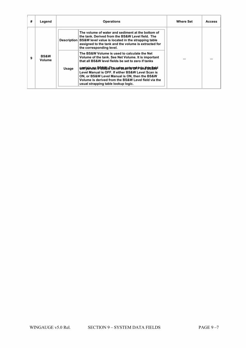
7/16/2019 3900 Manual
http://slidepdf.com/reader/full/3900-manual 227/266
WINGAUGE v5.0 Rel. SECTION 9 – SYSTEM DATA FIELDS PAGE 9 –7
# Legend Operations Where Set Access
9 BS&WVolume
Description
The volume of water and sediment at the bottom of the tank. Derived from the BS&W Level field. TheBS&W level value is located in the strapping tableassigned to the tank and the volume is extracted for the corresponding level.
Usage
The BS&W Volume is used to calculate the NetVolume of the tank. See Net Volume. It is importantthat all BS&W level fields be set to zero if tanks
contain no BS&W. The value entered into this fieldwill persist if BS&W Level Scan is OFF and BS&WLevel Manual is OFF. If either BS&W Level Scan isON, or BS&W Level Manual is ON, then the BS&WVolume is derived from the BS&W Level field via theusual strapping table lookup logic.
... ...
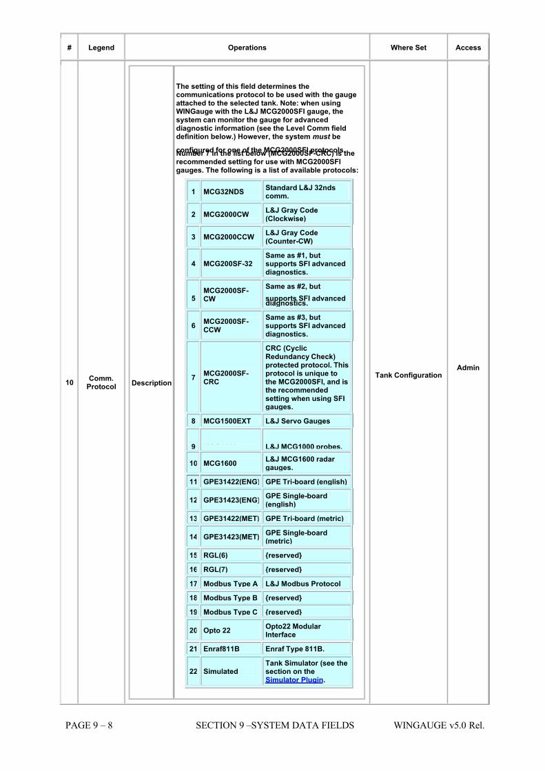
7/16/2019 3900 Manual
http://slidepdf.com/reader/full/3900-manual 228/266
PAGE 9 – 8 SECTION 9 –SYSTEM DATA FIELDS WINGAUGE v5.0 Rel.
# Legend Operations Where Set Access
10 Comm.Protocol Description
The setting of this field determines thecommunications protocol to be used with the gaugeattached to the selected tank. Note: when usingWINGauge with the L&J MCG2000SFI gauge, thesystem can monitor the gauge for advanceddiagnostic information (see the Level Comm fielddefinition below.) However, the system must be
configured for one of the MCG2000SFI protocols.Number 7 in the list below (MCG2000SF-CRC) is therecommended setting for use with MCG2000SFIgauges. The following is a list of available protocols:
1 MCG32NDS Standard L&J 32ndscomm.
2 MCG2000CW L&J Gray Code(Clockwise)
3 MCG2000CCW L&J Gray Code(Counter-CW)
4 MCG200SF-32 Same as #1, butsupports SFI advanceddiagnostics.
5 MCG2000SF-CW
Same as #2, but
supports SFI advanceddiagnostics.
6 MCG2000SF-CCW
Same as #3, butsupports SFI advanceddiagnostics.
7 MCG2000SF-CRC
CRC (CyclicRedundancy Check)protected protocol. Thisprotocol is unique tothe MCG2000SFI, and isthe recommendedsetting when using SFIgauges.
8 MCG1500EXT L&J Servo Gauges
9 MCG1000 L&J MCG1000 probes.
10 MCG1600 L&J MCG1600 radar gauges.
11 GPE31422(ENG) GPE Tri-board (english)
12 GPE31423(ENG)GPE Single-board(english)
13 GPE31422(MET) GPE Tri-board (metric)
14 GPE31423(MET)GPE Single-board(metric)
15 RGL(6) {reserved}
16 RGL(7) {reserved}
17 Modbus Type A L&J Modbus Protocol
18 Modbus Type B {reserved}
19 Modbus Type C {reserved}
20 Opto 22 Opto22 Modular Interface
21 Enraf811B Enraf Type 811B.
22 Simulated Tank Simulator (see thesection on theSimulator Plugin.
Tank Configuration Admin
7/16/2019 3900 Manual
http://slidepdf.com/reader/full/3900-manual 229/266
WINGAUGE v5.0 Rel. SECTION 9 – SYSTEM DATA FIELDS PAGE 9 –9
# Legend Operations Where Set Access
Usage
Open any of the listed pages in the Where Set columnfor this field and select the tank whose value is to bemodified. Click on the Comm Protocol field: adropdown list of the available protocols will appear.Choose the desired protocol from the list: the systemwill automatically save the selection and will continuegauging using the new protocol. Note that theupdated selection will not take effect until the
Advanced Gauging Module has completed polling onthe affected loop. For all L&J SFI series field devices,the protocol can be set to a variety of different styles.Verify the programming of the SFI Transmitter toensure the comm. protocol is programmed asdesired.
Impact
Many gauges support multiple protocols, and validdata will not be received if WINGauge and the gaugeare configured for incompatible protocols. Thecorrect comm. protocol will normally be programmedby L&J prior to shipment of the system. It isimperative that the proper Comm. protocol beselected to match the field device protocol. If it is not,incorrect or no data at all will result for level andtemperature information. If the user cannot find theproper communication protocol in the provided list of
the gauging program, they should consult L&JTechnical support before attempting any systemconfiguration.
11 CorrectionFactor
Description
API volume correction factor (1.0 @ 60 DEG .F). Thisvalue is unitless and is a system calculated valuebased on the product temperature as well as the APItable chosen in the system configuration page. In themajority of cases, the system should be set to AUTO
for API table selection. This will allow the gaugingprogram to automatically select the proper API tablefor the given gravity and temperature.
Usage This is a display-only field and cannot be edited.
Impact
Proper Correction factor calculations are imperativefor accurate Net Volume Calculations throughout thesystem. User should verify regularly that proper product temperature and gravity are available in thesystem for each tank to ensure accurate correctionfactors as well as Net Volume Calculations.
... ...
12 CPUPower
Description
MCG200SFI-only: This is the regulated power supplyvoltage being applied to the CPU board in the remotegauge. Nominally 5 volts DC, any significant changein this value may indicate a problem with the CPU's
power source or the on-board voltage regulator.
Usage This is a display-only field and cannot be edited.
... ...
7/16/2019 3900 Manual
http://slidepdf.com/reader/full/3900-manual 230/266
PAGE 9 – 10 SECTION 9 –SYSTEM DATA FIELDS WINGAUGE v5.0 Rel.
# Legend Operations Where Set Access
13 CPU Temp Description
MCG2000SFI-only: this value is the internal ambienttemperature of the gauge electronics package asmeasured from a thermal sensor mounted on theCPU board.
Usage This is a display-only field and cannot be edited.
... ...
14 CriticalTime
Description
Given that a tank is in motion and that a flow rate hasbeen detected, Critical Time is defined as the timeremaining for the product level to reach the highalarm level (if the tank is filling) or the low alarm level(if the tank is emptying.) The software automaticallydetermines the correct level to use from the directionof flow.
The calculated value for Critical Time is based uponthe current flow rate, current gross volume, and theprogrammed alarm level (after conversion to thecorresponding volume.) During each update cycle,the difference between the current volume and theapplicable alarm volume is divided by the flow rate togive Critical Time. Critical Time is viewed on-screenas hours and minutes (hhh:mm). It appears as a datafield on Tank Detail page (see example below), theFastGauge display, and as a user-selectable columnoption in the Tank Groups display. It is also availableas a display field in the Dynamic Forms Generator.
In all cases, if a tank is not in motion (no levelchange) and/or the flow rate is zero, the symbol "N/A"(Not Available) will appear instead of a Critical Timevalue. The target values for Critical Time are specifiedhere, via the High High, Hi-Hi, Low and Low-Low level
alarm set points. In this example, the High Level set point (7.106meters) corresponds to 4000 barrels of product inthis particular tank. Likewise, the Low Level value of 3.549 meters indicates a volume of 2000 barrels of product. When the Critical Time displays as zero, oneof these levels has been reached. The Critical Timevalue shown in the preceding example is ten hours,zero minutes. This number was determined via thefollowing simple calculation: Gross Volume = 3000barrels Flow Rate = 100 barrels per hour High Alarm =7.106 meters or 4000 barrels. Critical Time = (4000 -3000) / 100, or 10 hours.
Usage This is a display-only field and cannot be edited.
Impact
Allows user instant access to time remaining before
high or low alarm limits is exceeded, based upon thecurrent flow rate.
... ...
7/16/2019 3900 Manual
http://slidepdf.com/reader/full/3900-manual 231/266
WINGAUGE v5.0 Rel. SECTION 9 – SYSTEM DATA FIELDS PAGE 9 –11
# Legend Operations Where Set Access
15 CurrentRate
Description
This is the rate (displayed in the rate units specifiedon the System Configuration page) at which productis flowing in or out of a tank. If the displayed number is positive, product is flowing into the tank. If thenumber is negative, product is leaving the tank. Thisnumber is not based upon actual flow measurements,but is derived from the change in product volumeover time.
The volume change is calculated by the amount of level change detected each minute and thecorresponding volume change derived from the tankstrapping table.
Usage This is a display-only field and cannot be edited.
Impact
An accurate current rate value is essential for thesystem to calculate an accurate critical time. Thisallows the user to see how long it will take to reach ahigh or low alarm point at the current Rate of flow.Level active/inactive and time active/inactiveparameters must be set correctly for the system todetect that a tank is active.
... ...
16 Dead Tank
Description
A Dead Tank is defined as one in which no levelchanges are expected. Furthermore, if a level changeis detected, it is to be considered a problem state.Thus, if a tank has the Dead Tank option enabled, analarm will be generated if any motion is detected onthe tank.
Code Function
ON Alarm on tank movement.
OFF Do NOT alarm on tank movement.
Usage
Open any of the listed pages in the Where Set columnfor this field and select the tank whose value is to bemodified. Either click directly upon the Dead Tankfield to toggle the option ON or OFF, or use the Tabkey to navigate to the field and tap the Spacebar.
Impact This field determines if Dead Tank alarms will begenerated, and has no other effect.
Tank Configuration Admin
Super
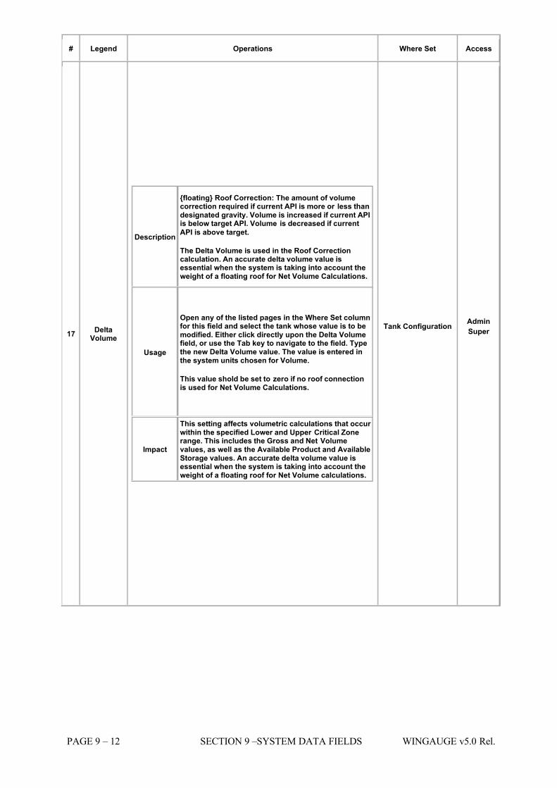
7/16/2019 3900 Manual
http://slidepdf.com/reader/full/3900-manual 232/266
PAGE 9 – 12 SECTION 9 –SYSTEM DATA FIELDS WINGAUGE v5.0 Rel.
# Legend Operations Where Set Access
17 DeltaVolume
Description
{floating} Roof Correction: The amount of volumecorrection required if current API is more or less thandesignated gravity. Volume is increased if current APIis below target API. Volume is decreased if current
API is above target.
The Delta Volume is used in the Roof Correctioncalculation. An accurate delta volume value isessential when the system is taking into account theweight of a floating roof for Net Volume Calculations.
Usage
Open any of the listed pages in the Where Set columnfor this field and select the tank whose value is to bemodified. Either click directly upon the Delta Volumefield, or use the Tab key to navigate to the field. Typethe new Delta Volume value. The value is entered inthe system units chosen for Volume.
This value shold be set to zero if no roof connectionis used for Net Volume Calculations.
Impact
This setting affects volumetric calculations that occur within the specified Lower and Upper Critical Zonerange. This includes the Gross and Net Volumevalues, as well as the Available Product and AvailableStorage values. An accurate delta volume value isessential when the system is taking into account theweight of a floating roof for Net Volume calculations.
Tank Configuration Admin
Super
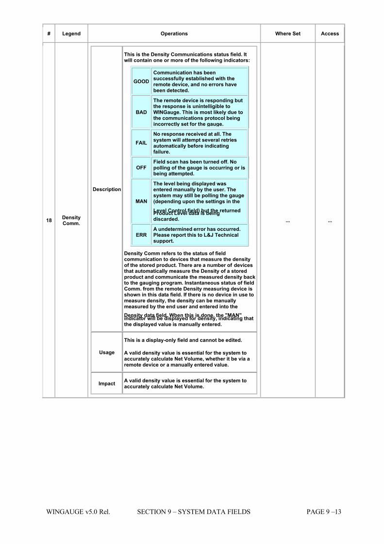
7/16/2019 3900 Manual
http://slidepdf.com/reader/full/3900-manual 233/266
WINGAUGE v5.0 Rel. SECTION 9 – SYSTEM DATA FIELDS PAGE 9 –13
# Legend Operations Where Set Access
18 DensityComm.
Description
This is the Density Communications status field. Itwill contain one or more of the following indicators:
GOOD Communication has beensuccessfully established with theremote device, and no errors havebeen detected.
BAD
The remote device is responding butthe response is unintelligible toWINGauge. This is most likely due tothe communications protocol beingincorrectly set for the gauge.
FAIL No response received at all. Thesystem will attempt several retriesautomatically before indicatingfailure.
OFF Field scan has been turned off. Nopolling of the gauge is occurring or isbeing attempted.
MAN
The level being displayed wasentered manually by the user. Thesystem may still be polling the gauge(depending upon the settings in the
Level Control field) but the returnedProduct Level data is beingdiscarded.
ERR A undetermined error has occurred.Please report this to L&J Technicalsupport.
Density Comm refers to the status of fieldcommunication to devices that measure the densityof the stored product. There are a number of devicesthat automatically measure the Density of a storedproduct and communicate the measured density backto the gauging program. Instantaneous status of fieldComm. from the remote Density measuring device isshown in this data field. If there is no device in use tomeasure density, the density can be manuallymeasured by the end user and entered into the
Density data field. When this is done, the "MAN"indicator will be displayed for density, indicating thatthe displayed value is manually entered.
Usage
This is a display-only field and cannot be edited.
A valid density value is essential for the system toaccurately calculate Net Volume, whether it be via aremote device or a manually entered value.
Impact A valid density value is essential for the system toaccurately calculate Net Volume.
... ...
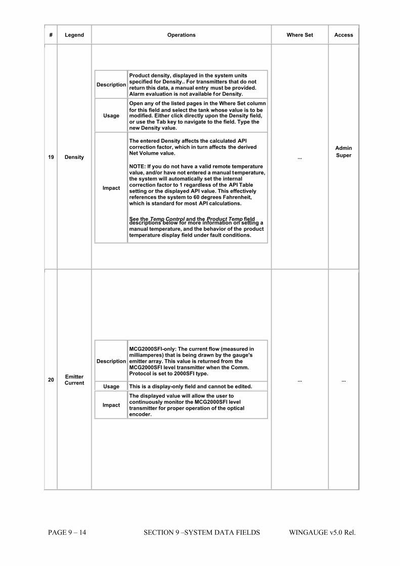
7/16/2019 3900 Manual
http://slidepdf.com/reader/full/3900-manual 234/266
PAGE 9 – 14 SECTION 9 –SYSTEM DATA FIELDS WINGAUGE v5.0 Rel.
# Legend Operations Where Set Access
19 Density
Description Product density, displayed in the system unitsspecified for Density.. For transmitters that do notreturn this data, a manual entry must be provided.Alarm evaluation is not available for Density.
Usage
Open any of the listed pages in the Where Set column
for this field and select the tank whose value is to bemodified. Either click directly upon the Density field,or use the Tab key to navigate to the field. Type thenew Density value.
Impact
The entered Density affects the calculated APIcorrection factor, which in turn affects the derivedNet Volume value.
NOTE: If you do not have a valid remote temperaturevalue, and/or have not entered a manual temperature,the system will automatically set the internalcorrection factor to 1 regardless of the API Tablesetting or the displayed API value. This effectivelyreferences the system to 60 degrees Fahrenheit,which is standard for most API calculations.
See the Temp Control and the Product Temp fielddescriptions below for more information on setting amanual temperature, and the behavior of the producttemperature display field under fault conditions.
... Admin
Super
20 Emitter Current
Description
MCG2000SFI-only: The current flow (measured inmilliamperes) that is being drawn by the gauge'semitter array. This value is returned from theMCG2000SFI level transmitter when the Comm.Protocol is set to 2000SFI type.
Usage This is a display-only field and cannot be edited.
Impact The displayed value will allow the user tocontinuously monitor the MCG2000SFI leveltransmitter for proper operation of the opticalencoder.
... ...
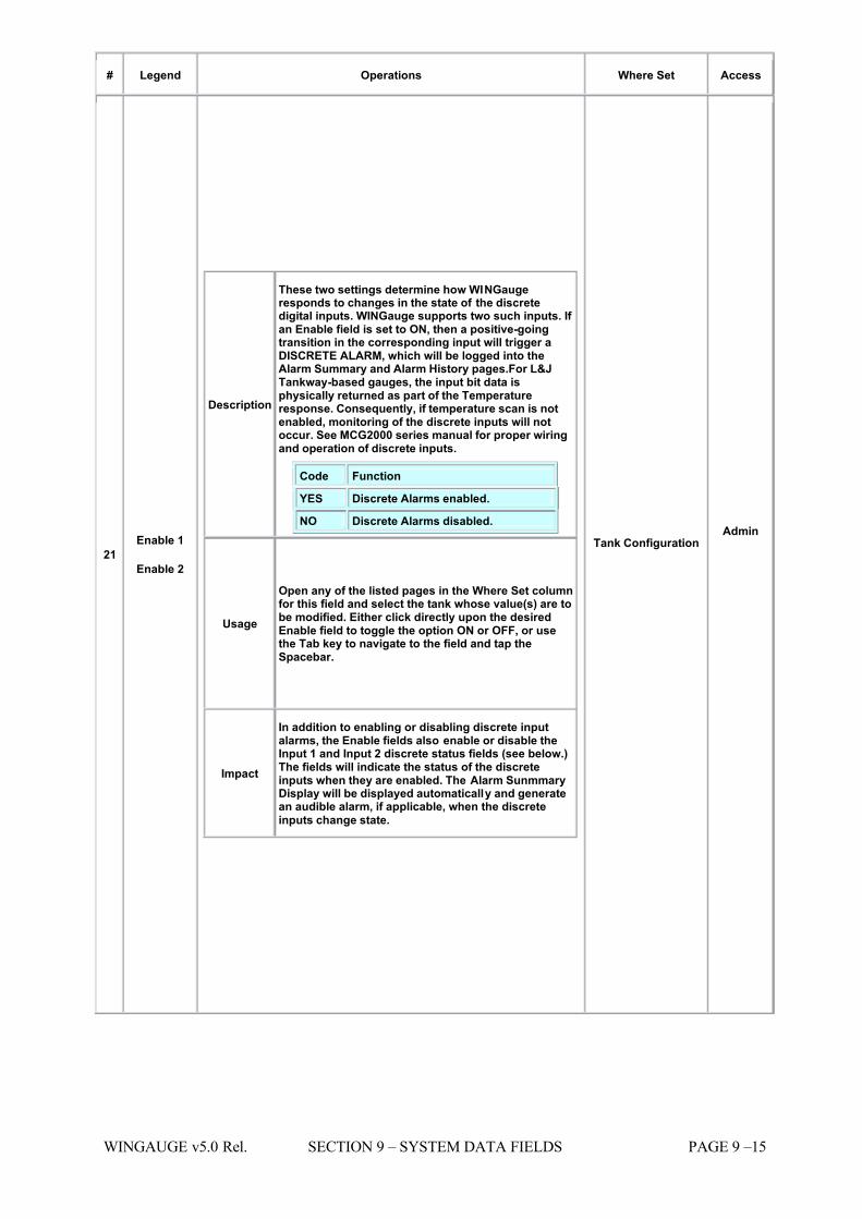
7/16/2019 3900 Manual
http://slidepdf.com/reader/full/3900-manual 235/266
WINGAUGE v5.0 Rel. SECTION 9 – SYSTEM DATA FIELDS PAGE 9 –15
# Legend Operations Where Set Access
21 Enable 1
Enable 2
Description
These two settings determine how WINGaugeresponds to changes in the state of the discretedigital inputs. WINGauge supports two such inputs. If an Enable field is set to ON, then a positive-goingtransition in the corresponding input will trigger aDISCRETE ALARM, which will be logged into theAlarm Summary and Alarm History pages.For L&JTankway-based gauges, the input bit data isphysically returned as part of the Temperatureresponse. Consequently, if temperature scan is notenabled, monitoring of the discrete inputs will notoccur. See MCG2000 series manual for proper wiringand operation of discrete inputs.
Code Function
YES Discrete Alarms enabled.
NO Discrete Alarms disabled.
Usage
Open any of the listed pages in the Where Set columnfor this field and select the tank whose value(s) are tobe modified. Either click directly upon the desiredEnable field to toggle the option ON or OFF, or usethe Tab key to navigate to the field and tap theSpacebar.
Impact
In addition to enabling or disabling discrete inputalarms, the Enable fields also enable or disable theInput 1 and Input 2 discrete status fields (see below.)The fields will indicate the status of the discreteinputs when they are enabled. The Alarm SunmmaryDisplay will be displayed automatically and generatean audible alarm, if applicable, when the discrete
inputs change state.
Tank Configuration Admin
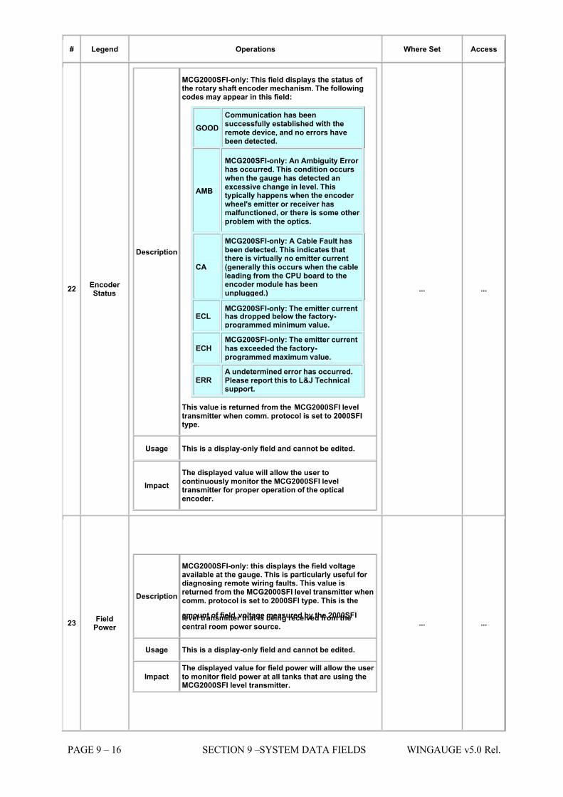
7/16/2019 3900 Manual
http://slidepdf.com/reader/full/3900-manual 236/266
PAGE 9 – 16 SECTION 9 –SYSTEM DATA FIELDS WINGAUGE v5.0 Rel.
# Legend Operations Where Set Access
22 Encoder Status
Description
MCG2000SFI-only: This field displays the status of the rotary shaft encoder mechanism. The followingcodes may appear in this field:
GOOD Communication has beensuccessfully established with theremote device, and no errors havebeen detected.
AMB
MCG200SFI-only: An Ambiguity Error has occurred. This condition occurswhen the gauge has detected anexcessive change in level. Thistypically happens when the encoder wheel's emitter or receiver hasmalfunctioned, or there is some other problem with the optics.
CA
MCG200SFI-only: A Cable Fault hasbeen detected. This indicates thatthere is virtually no emitter current(generally this occurs when the cableleading from the CPU board to theencoder module has beenunplugged.)
ECL MCG200SFI-only: The emitter currenthas dropped below the factory-programmed minimum value.
ECH MCG200SFI-only: The emitter currenthas exceeded the factory-programmed maximum value.
ERR A undetermined error has occurred.Please report this to L&J Technicalsupport.
This value is returned from the MCG2000SFI leveltransmitter when comm. protocol is set to 2000SFItype.
Usage This is a display-only field and cannot be edited.
Impact The displayed value will allow the user tocontinuously monitor the MCG2000SFI leveltransmitter for proper operation of the opticalencoder.
... ...
23 FieldPower
Description
MCG2000SFI-only: this displays the field voltageavailable at the gauge. This is particularly useful for diagnosing remote wiring faults. This value isreturned from the MCG2000SFI level transmitter whencomm. protocol is set to 2000SFI type. This is the
amount of field voltage measured by the 2000SFIlevel transmitter that is being received from thecentral room power source.
Usage This is a display-only field and cannot be edited.
Impact The displayed value for field power will allow the user to monitor field power at all tanks that are using theMCG2000SFI level transmitter.
... ...
7/16/2019 3900 Manual
http://slidepdf.com/reader/full/3900-manual 237/266
WINGAUGE v5.0 Rel. SECTION 9 – SYSTEM DATA FIELDS PAGE 9 –17
# Legend Operations Where Set Access
24 FloatAlarm
Description
This general-purpose alarm is typically used by anoperator as a reminder when a tank which is inmotion has reached a desired level. Simply enter thedesired target level (which should be above thecurrent level if the tank is filling, or below the currentlevel if the tank is emptying.) When the current levelequals or exceeds the programmed Float Alarm level,an alarm sound will be generated and the AlarmSummary page will be displayed automatically.
Usage
Open any of the listed pages in the Where Set columnfor this field and select the tank whose value is to bemodified. Either click directly upon the Float Alarmfield, or use the Tab key to navigate to the field. Typethe new Float Alarm level value. The value is enteredin the system units chosen for Level.
This value is always user-defined.
Impact
If the Float Alarm is enabled (a non-zero value hasbeen entered) the Critical Time field will reflect thecalculated time remaining until the Float Alarm levelwill be reached.
If the Float Alarm is disabled (a zero value has beenentered) the Critical Time field will reflect the timeremaining until the next standard alarm level value is
reached. The system will automatically select theproper alarm level to check based upon the currentlevel and tank movement direction. For moreinformation see the Critical Time field descriptionabove.
Tank Detail
Admin
Super
Operator
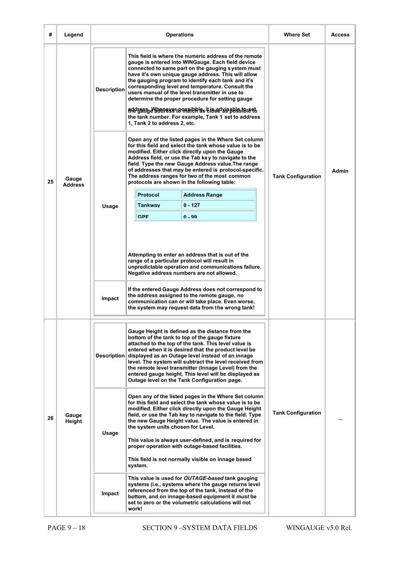
7/16/2019 3900 Manual
http://slidepdf.com/reader/full/3900-manual 238/266
PAGE 9 – 18 SECTION 9 –SYSTEM DATA FIELDS WINGAUGE v5.0 Rel.
# Legend Operations Where Set Access
25 GaugeAddress
Description
This field is where the numeric address of the remotegauge is entered into WINGauge. Each field deviceconnected to same part on the gauging system musthave it's own unique gauge address. This will allowthe gauging program to identify each tank and it'scorresponding level and temperature. Consult theusers manual of the level transmitter in use todetermine the proper procedure for setting gauge
address. Whenever possibble, it is advisable to setthe gauge address to match as close as possible tothe tank number. For example, Tank 1 set to address
1, Tank 2 to address 2, etc.
Usage
Open any of the listed pages in the Where Set columnfor this field and select the tank whose value is to bemodified. Either click directly upon the GaugeAddress field, or use the Tab key to navigate to thefield. Type the new Gauge Address value.The rangeof addresses that may be entered is protocol-specific.The address ranges for two of the most commonprotocols are shown in the following table:
Protocol Address Range
Tankway 0 - 127
GPE 0 - 99
Attempting to enter an address that is out of therange of a particular protocol will result inunpredictable operation and communications failure.Negative address numbers are not allowed.
Impact If the entered Gauge Address does not correspond tothe address assigned to the remote gauge, nocommunication can or will take place. Even worse,the system may request data from the wrong tank!
Tank Configuration Admin
26 GaugeHeight
Description
Gauge Height is defined as the distance from thebottom of the tank to top of the gauge fixtureattached to the top of the tank. This level value isentered when it is desired that the product level bedisplayed as an Outage level instead of an innagelevel. The system will subtract the level received fromthe remote level transmitter (Innage Level) from theentered gauge height. This level will be displayed asOutage level on the Tank Configuration page.
Usage
Open any of the listed pages in the Where Set columnfor this field and select the tank whose value is to bemodified. Either click directly upon the Gauge Heightfield, or use the Tab key to navigate to the field. Typethe new Gauge Height value. The value is entered inthe system units chosen for Level.
This value is always user-defined, and is required for proper operation with outage-based facilities.
This field is not normally visible on innage basedsystem.
Impact
This value is used for OUTAGE-based tank gaugingsystems (i.e., systems where the gauge returns levelreferenced from the top of the tank, instead of thebottom, and on innage-based equipment it must beset to zero or the volumetric calculations will notwork!
Tank Configuration ...
7/16/2019 3900 Manual
http://slidepdf.com/reader/full/3900-manual 239/266
WINGAUGE v5.0 Rel. SECTION 9 – SYSTEM DATA FIELDS PAGE 9 –19
# Legend Operations Where Set Access
27 GrossVolume
Description
The Gross (uncorrected) Volume. The Gross Volumeis determined by indexing the current Product Levelinto the assigned Strapping Table for the tank. Nooffsets, scaling factors, or other corrections havebeen applied to the volume at this point.
Usage This is a display-only field and cannot be edited.
Impact
Accurate product level measurement as well as a
properly entered strapping table are required for gross volume values to be calculated correctly.
... ...
28 Group
Code
Description
This is the alphanumeric code assigned to a group of related products. In other words, while each tank isgiven a product code which indicates the type of product stored in the tank, the group code refers toone or more tanks that contain products that are insome way similar. For example a product group of Crude Oil might have tanks containing different typesof Crude: Texas Sweet, Texas Sour, Low Sulfur, etc.
Usage The available Group Codes are defined externally tothe WINGauge in a separate data file. This file isnormally maintained by the system administrator.
Impact
Group Codes are used on the following displays andpages: Group Display, Group Summary, GroupSummary Graph and Inventory On-Hand.
They are also used on the printed Product Summaryand Inventory reports. To allow the gauging systemto accurately generate displays and reports for eachgroup of products, it is important that all productscodes related to a group code be assigned correctlyby the system administrator. Accurate inventoryreports are dependent on proper configuration of both product and group codes.
{Data File}
Admin
29 High Level
Description
Alarm Setpoint: when the current level equals or exceeds this value, a High Level alarm will occur. The
alarm condition will be logged to both the AlarmSummary and Alarm History displays, andappropriate alarm colors will be generated ondisplays that support them. Multimedia equippedsystems will generate a warning class alarm soundfrom the speakers.
Usage
Open any of the listed pages in the Where Set columnfor this field and select the tank whose value is to bemodified. Either click directly upon the High Levelfield, or use the Tab key to navigate to the field. Typethe new High Level value. The value is entered in thesystem units chosen for Level.
This value is always user-defined.
Impact
The system level alarm detection and evaluation
routines depend entirely upon the proper setting of the various alarm levels. Failure to set the alarmlevels correctly may cause the system to generatespurious alarms or fail to detect dangerousconditions.
Tank Detail
Admin
Super
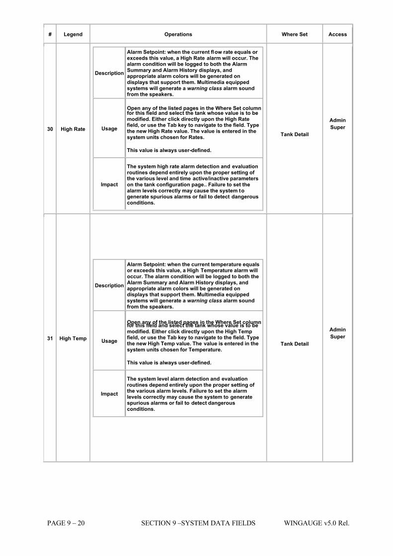
7/16/2019 3900 Manual
http://slidepdf.com/reader/full/3900-manual 240/266
PAGE 9 – 20 SECTION 9 –SYSTEM DATA FIELDS WINGAUGE v5.0 Rel.
# Legend Operations Where Set Access
30 High Rate
Description
Alarm Setpoint: when the current flow rate equals or exceeds this value, a High Rate alarm will occur. Thealarm condition will be logged to both the AlarmSummary and Alarm History displays, andappropriate alarm colors will be generated ondisplays that support them. Multimedia equippedsystems will generate a warning class alarm soundfrom the speakers.
Usage
Open any of the listed pages in the Where Set columnfor this field and select the tank whose value is to bemodified. Either click directly upon the High Ratefield, or use the Tab key to navigate to the field. Typethe new High Rate value. The value is entered in thesystem units chosen for Rates.
This value is always user-defined.
Impact
The system high rate alarm detection and evaluationroutines depend entirely upon the proper setting of the various level and time active/inactive parameterson the tank configuration page.. Failure to set thealarm levels correctly may cause the system togenerate spurious alarms or fail to detect dangerousconditions.
Tank Detail
Admin
Super
31 High Temp
Description
Alarm Setpoint: when the current temperature equalsor exceeds this value, a High Temperature alarm willoccur. The alarm condition will be logged to both theAlarm Summary and Alarm History displays, andappropriate alarm colors will be generated ondisplays that support them. Multimedia equippedsystems will generate a warning class alarm soundfrom the speakers.
Usage
Open any of the listed pages in the Where Set columnfor this field and select the tank whose value is to bemodified. Either click directly upon the High Tempfield, or use the Tab key to navigate to the field. Typethe new High Temp value. The value is entered in thesystem units chosen for Temperature.
This value is always user-defined.
Impact
The system level alarm detection and evaluationroutines depend entirely upon the proper setting of the various alarm levels. Failure to set the alarmlevels correctly may cause the system to generatespurious alarms or fail to detect dangerousconditions.
Tank Detail
Admin
Super
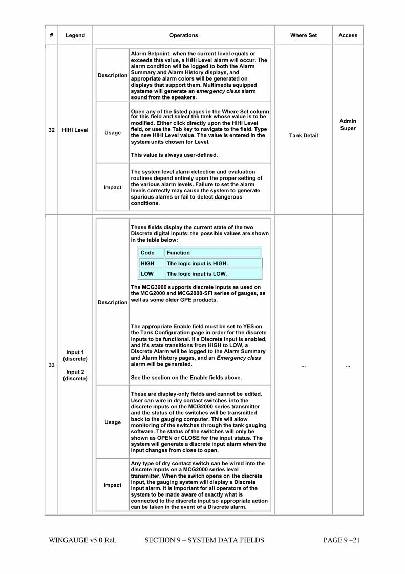
7/16/2019 3900 Manual
http://slidepdf.com/reader/full/3900-manual 241/266
WINGAUGE v5.0 Rel. SECTION 9 – SYSTEM DATA FIELDS PAGE 9 –21
# Legend Operations Where Set Access
32 HiHi Level
Description
Alarm Setpoint: when the current level equals or exceeds this value, a HiHi Level alarm will occur. Thealarm condition will be logged to both the AlarmSummary and Alarm History displays, andappropriate alarm colors will be generated ondisplays that support them. Multimedia equippedsystems will generate an emergency class alarmsound from the speakers.
Usage
Open any of the listed pages in the Where Set columnfor this field and select the tank whose value is to bemodified. Either click directly upon the HiHi Levelfield, or use the Tab key to navigate to the field. Typethe new HiHi Level value. The value is entered in thesystem units chosen for Level.
This value is always user-defined.
Impact
The system level alarm detection and evaluationroutines depend entirely upon the proper setting of the various alarm levels. Failure to set the alarmlevels correctly may cause the system to generatespurious alarms or fail to detect dangerousconditions.
Tank Detail
Admin
Super
33
Input 1(discrete)
Input 2(discrete)
Description
These fields display the current state of the twoDiscrete digital inputs: the possible values are shownin the table below:
Code Function
HIGH The logic input is HIGH.
LOW The logic input is LOW.
The MCG3900 supports discrete inputs as used onthe MCG2000 and MCG2000-SFI series of gauges, aswell as some older GPE products.
The appropriate Enable field must be set to YES onthe Tank Configuration page in order for the discreteinputs to be functional. If a Discrete Input is enabled,and it's state transitions from HIGH to LOW, aDiscrete Alarm will be logged to the Alarm Summaryand Alarm History pages, and an Emergency class alarm will be generated.
See the section on the Enable fields above.
Usage
These are display-only fields and cannot be edited.User can wire in dry contact switches into thediscrete inputs on the MCG2000 series transmitter and the status of the switches will be transmittedback to the gauging computer. This will allowmonitoring of the switches through the tank gaugingsoftware. The status of the switches will only beshown as OPEN or CLOSE for the input status. Thesystem will generate a discrete input alarm when the
input changes from close to open.
Impact
Any type of dry contact switch can be wired into thediscrete inputs on a MCG2000 series leveltransmitter. When the switch opens on the discreteinput, the gauging system will display a Discreteinput alarm. It is important for all operators of thesystem to be made aware of exactly what isconnected to the discrete input so appropriate actioncan be taken in the event of a Discrete alarm.
... ...
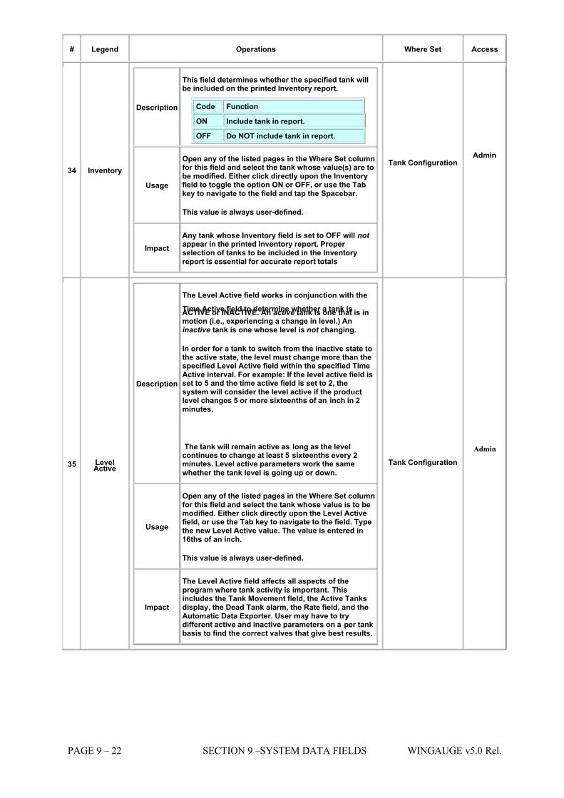
7/16/2019 3900 Manual
http://slidepdf.com/reader/full/3900-manual 242/266
PAGE 9 – 22 SECTION 9 –SYSTEM DATA FIELDS WINGAUGE v5.0 Rel.
# Legend Operations Where Set Access
34 Inventory
Description
This field determines whether the specified tank willbe included on the printed Inventory report.
Code Function
ON Include tank in report.
OFF Do NOT include tank in report.
Usage
Open any of the listed pages in the Where Set columnfor this field and select the tank whose value(s) are tobe modified. Either click directly upon the Inventoryfield to toggle the option ON or OFF, or use the Tabkey to navigate to the field and tap the Spacebar.
This value is always user-defined.
Impact Any tank whose Inventory field is set to OFF will not appear in the printed Inventory report. Proper selection of tanks to be included in the Inventoryreport is essential for accurate report totals
Tank Configuration Admin
35 LevelActive
Description
The Level Active field works in conjunction with the
Time Active field to determine whether a tank isACTIVE or INACTIVE. An active tank is one that is inmotion (i.e., experiencing a change in level.) Aninactive tank is one whose level is not changing.
In order for a tank to switch from the inactive state tothe active state, the level must change more than thespecified Level Active field within the specified TimeActive interval. For example: If the level active field isset to 5 and the time active field is set to 2, thesystem will consider the level active if the productlevel changes 5 or more sixteenths of an inch in 2minutes.
The tank will remain active as long as the levelcontinues to change at least 5 sixteenths every 2minutes. Level active parameters work the same
whether the tank level is going up or down.
Usage
Open any of the listed pages in the Where Set columnfor this field and select the tank whose value is to bemodified. Either click directly upon the Level Activefield, or use the Tab key to navigate to the field. Typethe new Level Active value. The value is entered in16ths of an inch.
This value is always user-defined.
Impact
The Level Active field affects all aspects of theprogram where tank activity is important. Thisincludes the Tank Movement field, the Active Tanksdisplay, the Dead Tank alarm, the Rate field, and theAutomatic Data Exporter. User may have to trydifferent active and inactive parameters on a per tankbasis to find the correct valves that give best results.
Tank Configuration
Admin
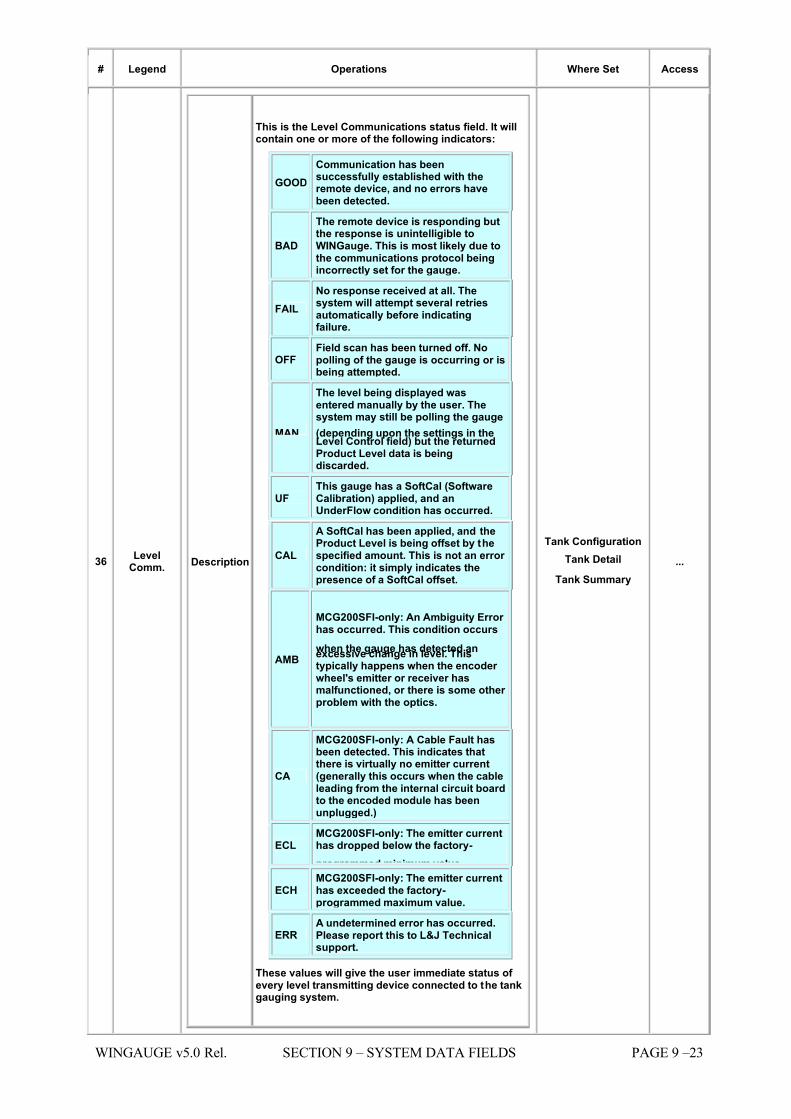
7/16/2019 3900 Manual
http://slidepdf.com/reader/full/3900-manual 243/266
WINGAUGE v5.0 Rel. SECTION 9 – SYSTEM DATA FIELDS PAGE 9 –23
# Legend Operations Where Set Access
36 LevelComm. Description
This is the Level Communications status field. It willcontain one or more of the following indicators:
GOOD Communication has beensuccessfully established with theremote device, and no errors havebeen detected.
BAD
The remote device is responding butthe response is unintelligible toWINGauge. This is most likely due tothe communications protocol beingincorrectly set for the gauge.
FAIL No response received at all. Thesystem will attempt several retriesautomatically before indicatingfailure.
OFF Field scan has been turned off. Nopolling of the gauge is occurring or isbeing attempted.
MAN
The level being displayed wasentered manually by the user. Thesystem may still be polling the gauge
(depending upon the settings in theLevel Control field) but the returnedProduct Level data is beingdiscarded.
UF This gauge has a SoftCal (SoftwareCalibration) applied, and anUnderFlow condition has occurred.
CAL
A SoftCal has been applied, and theProduct Level is being offset by thespecified amount. This is not an error condition: it simply indicates thepresence of a SoftCal offset.
AMB
MCG200SFI-only: An Ambiguity Error has occurred. This condition occurs
when the gauge has detected anexcessive change in level. Thistypically happens when the encoder wheel's emitter or receiver hasmalfunctioned, or there is some other problem with the optics.
CA
MCG200SFI-only: A Cable Fault hasbeen detected. This indicates thatthere is virtually no emitter current(generally this occurs when the cableleading from the internal circuit boardto the encoded module has beenunplugged.)
ECL MCG200SFI-only: The emitter currenthas dropped below the factory-
programmed minimum value.
ECH MCG200SFI-only: The emitter currenthas exceeded the factory-programmed maximum value.
ERR A undetermined error has occurred.Please report this to L&J Technicalsupport.
These values will give the user immediate status of every level transmitting device connected to the tankgauging system.
Tank Configuration Tank Detail
Tank Summary ...
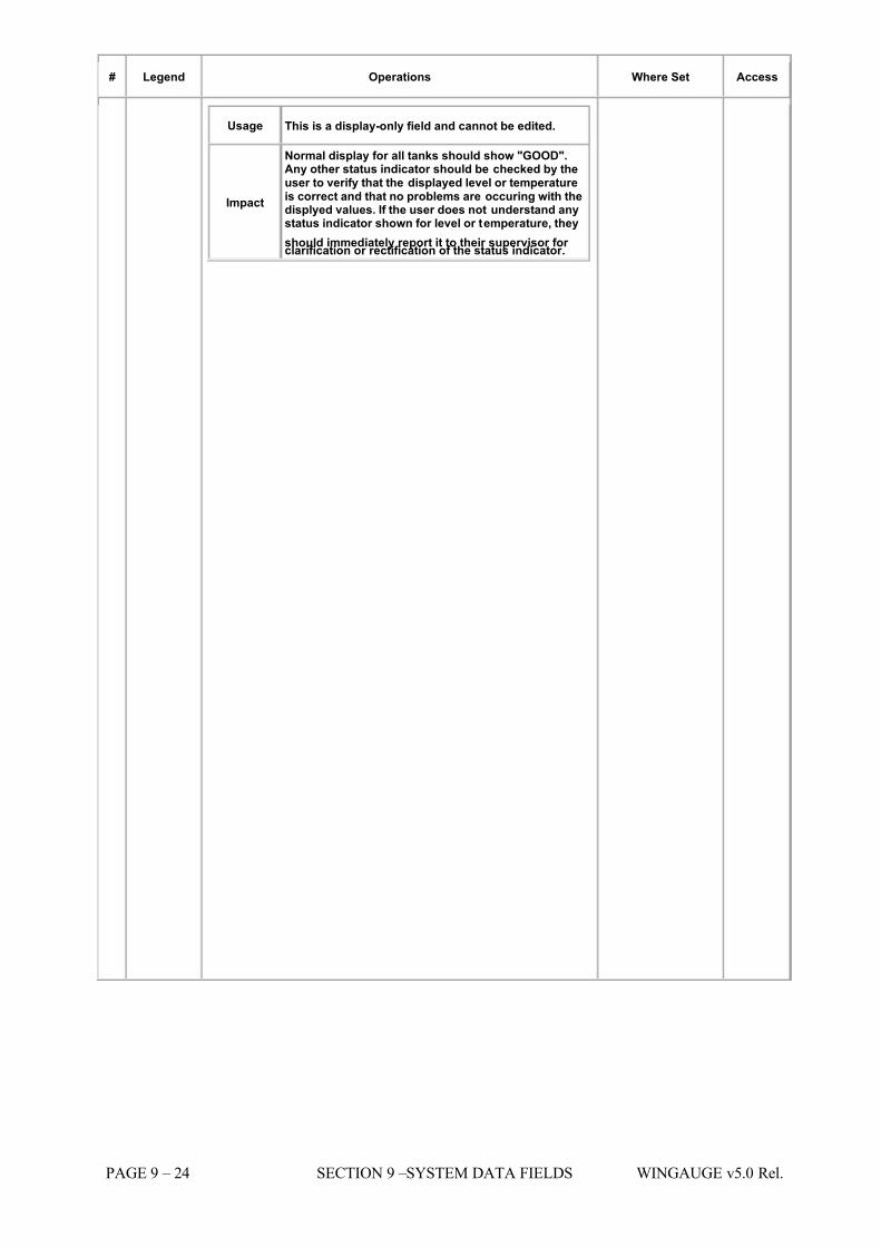
7/16/2019 3900 Manual
http://slidepdf.com/reader/full/3900-manual 244/266
PAGE 9 – 24 SECTION 9 –SYSTEM DATA FIELDS WINGAUGE v5.0 Rel.
# Legend Operations Where Set Access
Usage This is a display-only field and cannot be edited.
Impact
Normal display for all tanks should show "GOOD".Any other status indicator should be checked by theuser to verify that the displayed level or temperatureis correct and that no problems are occuring with thedisplyed values. If the user does not understand anystatus indicator shown for level or temperature, they
should immediately report it to their supervisor for clarification or rectification of the status indicator.
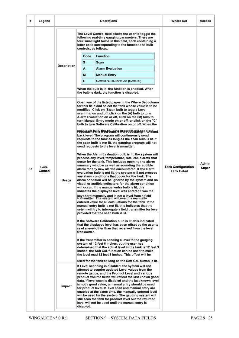
7/16/2019 3900 Manual
http://slidepdf.com/reader/full/3900-manual 245/266
WINGAUGE v5.0 Rel. SECTION 9 – SYSTEM DATA FIELDS PAGE 9 –25
# Legend Operations Where Set Access
37 LevelControl
Description
The Level Control field allows the user to toggle thefollowing real-time gauging parameters. There arefour small light bulbs in this field, each containing aletter code corresponding to the function the bulbcontrols, as follows:
Code Function
S
Scan
A Alarm Evaluation
M Manual Entry
C Software Calibration (SoftCal)
When the bulb is lit, the function is enabled. Whenthe bulb is dark, the function is disabled.
Usage
Open any of the listed pages in the Where Set columnfor this field and select the tank whose value is to bemodified. Click on (S)can bulb to toggle Levelscanning on and off, click on the (A) bulb to turnAlarm Evaluation on or off, click on the (M) bulb toturn Manual Entry mode on or off, or click on the "C"bulb to turn Software Calibration on or off. When the
scan bulb is lit, the gauging program will send outrequests to the level transmitter requesting it to sendback level. The program will continuously sendrequests to the tank as long as the scan bulb is lit. If the scan bulb is not lit, the gauging program will notsend requests to the level transmitter.
When the Alarm Evaluation bulb is lit, the system willprocess any level, temperature, rate, etc. alarms thatoccur for the tank. This includes opening the alarmsummary window as well as sounding the audiblealarm for any new alarms encountered. If the alarmevaluation bulb is not lit, the system will not processany alarm conditions that occur for the tank. Thealarm condition will be ignored by the system and novisual or audible indicators for the alarm conditionwill occur. If the manual entry bulb is lit, thisindicates the displayed level was entered from the
keyboard manually and is not a level from a fieldtransmitter. The system will use this manuallyentered value for all calculations for the tank. If themanual entry bulb is not lit, this indicates that thesytem will try to interogate a field transmitter for levelprovided that the scan bulb is lit.
If the Software Calibration bulb is lit, this indicatedthat the displayed level has been offset by the user toread a level other than that received from the leveltransmitter.
If the transmitter is sending a level to the gaugingsystem of 12 feet 6 inches, but the user hasdetermined that the actual level in the tank is 12 feet 3inches, the Soft Cal. function can be used to makethe level read 12 feet 3 inches. This offset will be
used for the tank as long as the Soft Cal. button is lit.
Impact
If Level scanning is disabled, the system will notattempt to acquire updated Level values from theremote gauge, and the Product Level and variousproduct volume fields will reflect the last known gooddata. If level scan is disabled and the last known levelis not a good value, a manual entry should be usedfor product level. If level scan and manual entry areenabled at the same time, the manually entered levelwill be used by the system. The gauging system willstill scan the tank for product level but the returnedlevel will not be used until the manual entry isdisabled.
Tank Configuration Tank Detail
Admin
Super
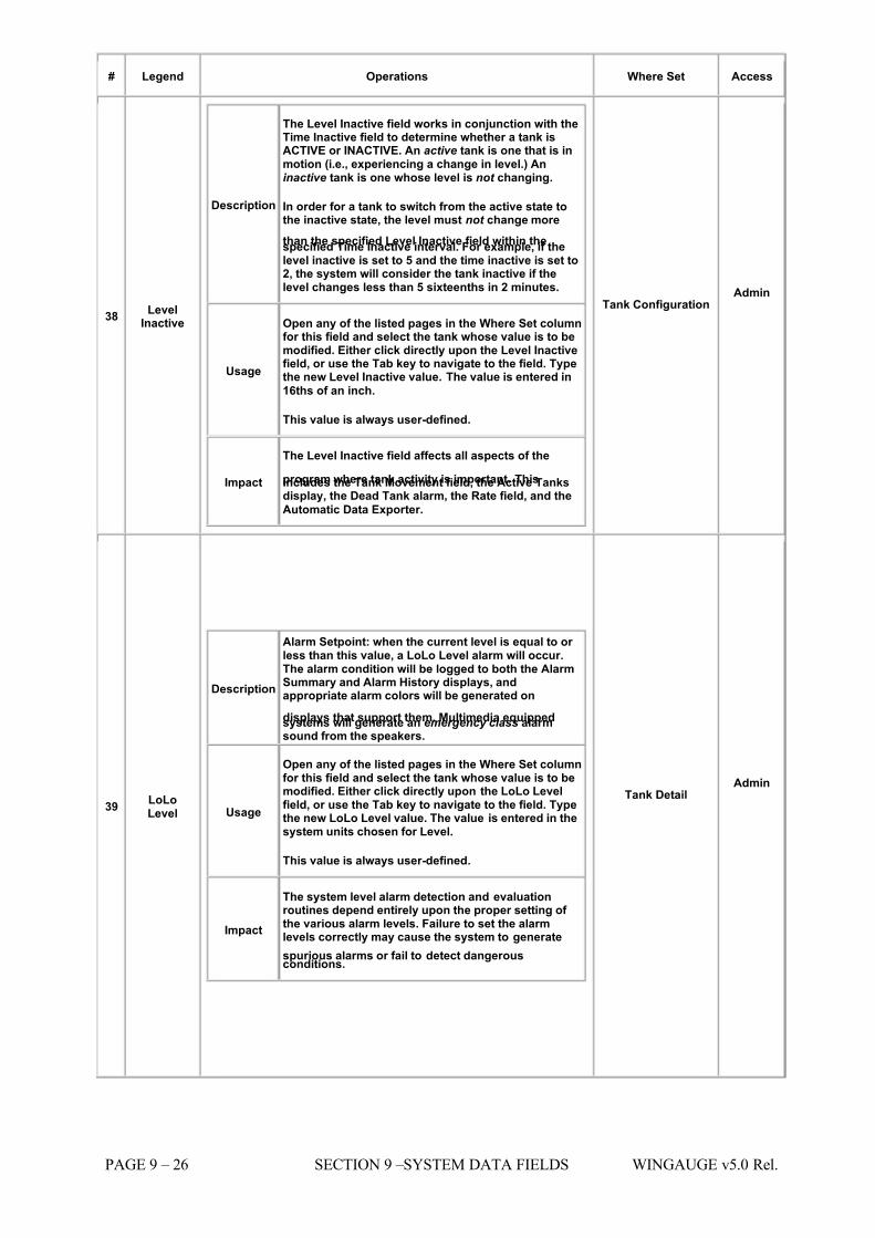
7/16/2019 3900 Manual
http://slidepdf.com/reader/full/3900-manual 246/266
PAGE 9 – 26 SECTION 9 –SYSTEM DATA FIELDS WINGAUGE v5.0 Rel.
# Legend Operations Where Set Access
38 LevelInactive
Description
The Level Inactive field works in conjunction with theTime Inactive field to determine whether a tank isACTIVE or INACTIVE. An active tank is one that is inmotion (i.e., experiencing a change in level.) Aninactive tank is one whose level is not changing.
In order for a tank to switch from the active state tothe inactive state, the level must not change more
than the specified Level Inactive field within thespecified Time Inactive interval. For example, if thelevel inactive is set to 5 and the time inactive is set to2, the system will consider the tank inactive if thelevel changes less than 5 sixteenths in 2 minutes.
Usage
Open any of the listed pages in the Where Set columnfor this field and select the tank whose value is to bemodified. Either click directly upon the Level Inactivefield, or use the Tab key to navigate to the field. Typethe new Level Inactive value. The value is entered in
16ths of an inch.
This value is always user-defined.
Impact
The Level Inactive field affects all aspects of the
program where tank activity is important. Thisincludes the Tank Movement field, the Active Tanksdisplay, the Dead Tank alarm, the Rate field, and the
Automatic Data Exporter.
Tank Configuration Admin
39 LoLoLevel
Description
Alarm Setpoint: when the current level is equal to or less than this value, a LoLo Level alarm will occur.The alarm condition will be logged to both the AlarmSummary and Alarm History displays, andappropriate alarm colors will be generated on
displays that support them. Multimedia equippedsystems will generate an emergency class alarmsound from the speakers.
Usage
Open any of the listed pages in the Where Set columnfor this field and select the tank whose value is to bemodified. Either click directly upon the LoLo Levelfield, or use the Tab key to navigate to the field. Typethe new LoLo Level value. The value is entered in thesystem units chosen for Level.
This value is always user-defined.
Impact
The system level alarm detection and evaluationroutines depend entirely upon the proper setting of the various alarm levels. Failure to set the alarmlevels correctly may cause the system to generate
spurious alarms or fail to detect dangerousconditions.
Tank Detail Admin
7/16/2019 3900 Manual
http://slidepdf.com/reader/full/3900-manual 247/266
WINGAUGE v5.0 Rel. SECTION 9 – SYSTEM DATA FIELDS PAGE 9 –27
# Legend Operations Where Set Access
40 LoopNumber
Description
This field is where the numeric Loop Number of theremote gauge is entered into WINGauge. The loopnumbers will be pre-defined by L&J Engineering andthe user's system administrator. The gauging loop isthe actual communication port in the gaugingcomputer that the field transmitters are connected to.A typical connection would be to use serial portsCom 1 or Com 2 for example.
Usage
Open any of the listed pages in the Where Set columnfor this field and select the tank whose value is to bemodified. Either click directly upon the Loop Number field, or use the Tab key to navigate to the field. Typethe new Loop Number value.
Loop Numbers can range from 1 to 32 (WINGaugesupports a maximum of 32 gauging loops.) Loopscorrespond to physical interface ports, and the actualassignment of a Loop Number to a physical port isdetermined by the system administrator.
Impact
If the entered Loop Number does not correspond to aphysical communications port connected to a gaugeloop, no communication can or will take place. It isentirely possible to set this number to a valid butincorrect loop, in which case the system could record
data from the wrong tanks.
Tank Configuration Admin
42 Low Level
Description
Alarm Setpoint: when the current level is equal to or less than this value, a Low Level alarm will occur. Thealarm condition will be logged to both the AlarmSummary and Alarm History displays, andappropriate alarm colors will be generated ondisplays that support them. Multimedia equippedsystems will generate a warning class alarm soundfrom the speakers.
Usage
Open any of the listed pages in the Where Set columnfor this field and select the tank whose value is to bemodified. Either click directly upon the Low Levelfield, or use the Tab key to navigate to the field. Typethe new Low Level value. The value is entered in the
system units chosen for Level. This value is always user-defined.
Impact
The system level alarm detection and evaluationroutines depend entirely upon the proper setting of the various alarm levels. Failure to set the alarmlevels correctly may cause the system to generatespurious alarms or fail to detect dangerousconditions.
Tank Detail
Admin
43 Low Rate
Description
Alarm Setpoint: when the current flow rate dropsbelow this value, a Low Rate alarm will occur. Thealarm condition will be logged to both the AlarmSummary and Alarm History displays, andappropriate alarm colors will be generated ondisplays that support them. Multimedia equippedsystems will generate a warning class alarm soundfrom the speakers.
Usage
Open any of the listed pages in the Where Set columnfor this field and select the tank whose value is to bemodified. Either click directly upon the Low Ratefield, or use the Tab key to navigate to the field. Typethe new Low Rate value. The value is entered in thesystem units chosen for Rates.
This value is always user-defined.
Tank Detail
Admin
Super
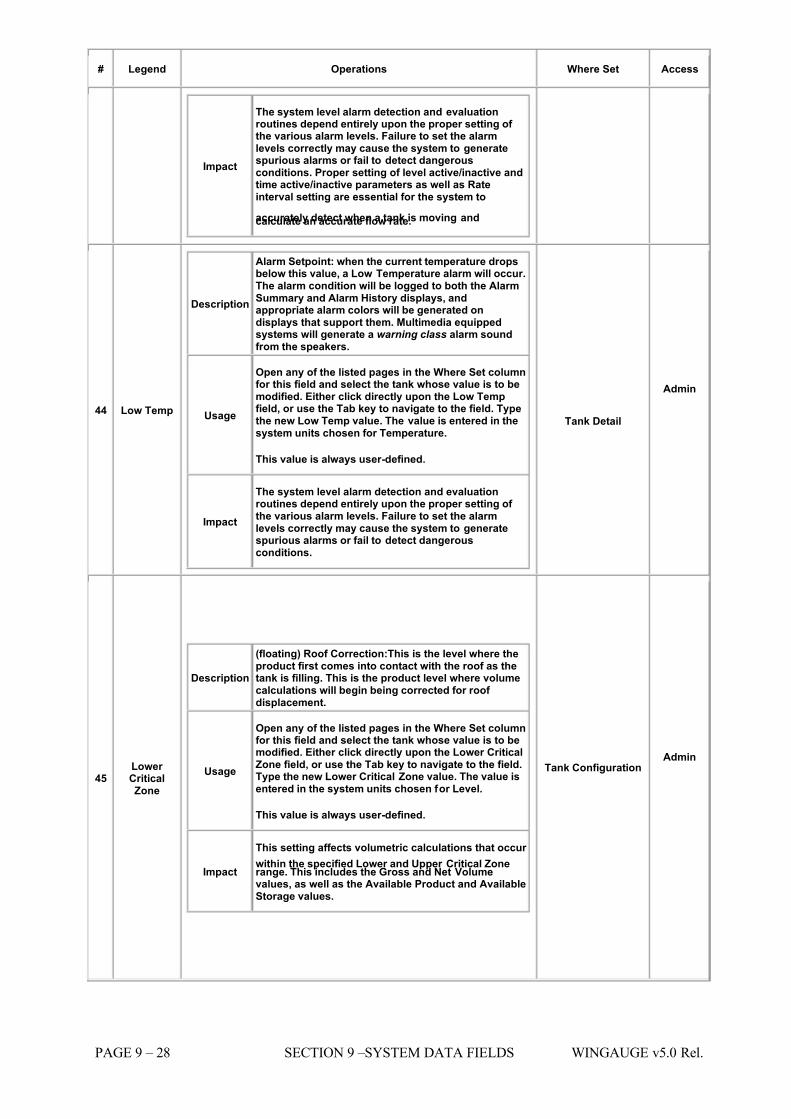
7/16/2019 3900 Manual
http://slidepdf.com/reader/full/3900-manual 248/266
PAGE 9 – 28 SECTION 9 –SYSTEM DATA FIELDS WINGAUGE v5.0 Rel.
# Legend Operations Where Set Access
Impact
The system level alarm detection and evaluationroutines depend entirely upon the proper setting of the various alarm levels. Failure to set the alarmlevels correctly may cause the system to generatespurious alarms or fail to detect dangerousconditions. Proper setting of level active/inactive andtime active/inactive parameters as well as Rateinterval setting are essential for the system to
accurately detect when a tank is moving andcalculate an accurate flow rate.
44 Low Temp
Description
Alarm Setpoint: when the current temperature dropsbelow this value, a Low Temperature alarm will occur.The alarm condition will be logged to both the AlarmSummary and Alarm History displays, andappropriate alarm colors will be generated ondisplays that support them. Multimedia equippedsystems will generate a warning class alarm soundfrom the speakers.
Usage
Open any of the listed pages in the Where Set columnfor this field and select the tank whose value is to bemodified. Either click directly upon the Low Tempfield, or use the Tab key to navigate to the field. Typethe new Low Temp value. The value is entered in thesystem units chosen for Temperature.
This value is always user-defined.
Impact
The system level alarm detection and evaluationroutines depend entirely upon the proper setting of the various alarm levels. Failure to set the alarmlevels correctly may cause the system to generatespurious alarms or fail to detect dangerousconditions.
Tank Detail
Admin
45 Lower CriticalZone
Description
(floating) Roof Correction:This is the level where theproduct first comes into contact with the roof as thetank is filling. This is the product level where volumecalculations will begin being corrected for roof displacement.
Usage
Open any of the listed pages in the Where Set columnfor this field and select the tank whose value is to bemodified. Either click directly upon the Lower CriticalZone field, or use the Tab key to navigate to the field.Type the new Lower Critical Zone value. The value isentered in the system units chosen for Level.
This value is always user-defined.
Impact
This setting affects volumetric calculations that occur
within the specified Lower and Upper Critical Zonerange. This includes the Gross and Net Volumevalues, as well as the Available Product and AvailableStorage values.
Tank Configuration Admin
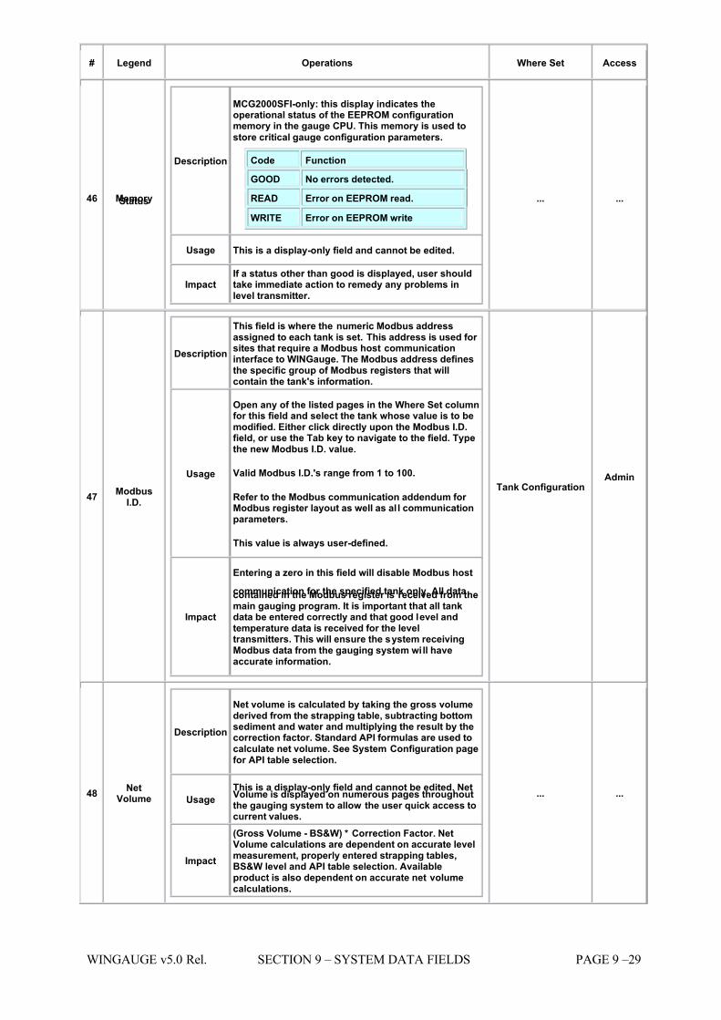
7/16/2019 3900 Manual
http://slidepdf.com/reader/full/3900-manual 249/266
WINGAUGE v5.0 Rel. SECTION 9 – SYSTEM DATA FIELDS PAGE 9 –29
# Legend Operations Where Set Access
46 MemoryStatus
Description
MCG2000SFI-only: this display indicates theoperational status of the EEPROM configurationmemory in the gauge CPU. This memory is used to
store critical gauge configuration parameters.
Code Function
GOOD No errors detected.
READ Error on EEPROM read. WRITE Error on EEPROM write
Usage This is a display-only field and cannot be edited.
Impact If a status other than good is displayed, user shouldtake immediate action to remedy any problems inlevel transmitter.
... ...
47 ModbusI.D.
Description
This field is where the numeric Modbus addressassigned to each tank is set. This address is used for sites that require a Modbus host communicationinterface to WINGauge. The Modbus address definesthe specific group of Modbus registers that willcontain the tank's information.
Usage
Open any of the listed pages in the Where Set columnfor this field and select the tank whose value is to bemodified. Either click directly upon the Modbus I.D.field, or use the Tab key to navigate to the field. Typethe new Modbus I.D. value.
Valid Modbus I.D.'s range from 1 to 100.
Refer to the Modbus communication addendum for Modbus register layout as well as al l communicationparameters.
This value is always user-defined.
Impact
Entering a zero in this field will disable Modbus host
communication for the specified tank only. All datacontained in the Modbus register is received from themain gauging program. It is important that all tankdata be entered correctly and that good level andtemperature data is received for the leveltransmitters. This will ensure the system receivingModbus data from the gauging system will haveaccurate information.
Tank Configuration Admin
48 NetVolume
Description
Net volume is calculated by taking the gross volumederived from the strapping table, subtracting bottomsediment and water and multiplying the result by thecorrection factor. Standard API formulas are used tocalculate net volume. See System Configuration pagefor API table selection.
Usage This is a display-only field and cannot be edited. NetVolume is displayed on numerous pages throughoutthe gauging system to allow the user quick access tocurrent values.
Impact
(Gross Volume - BS&W) * Correction Factor. NetVolume calculations are dependent on accurate levelmeasurement, properly entered strapping tables,BS&W level and API table selection. Availableproduct is also dependent on accurate net volumecalculations.
... ...
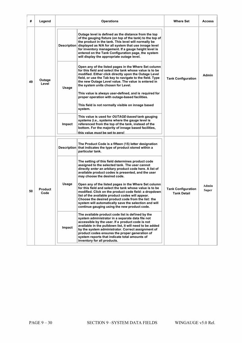
7/16/2019 3900 Manual
http://slidepdf.com/reader/full/3900-manual 250/266
PAGE 9 – 30 SECTION 9 –SYSTEM DATA FIELDS WINGAUGE v5.0 Rel.
# Legend Operations Where Set Access
49 OutageLevel
Description
Outage level is defined as the distance from the topof the gauging fixture (on top of the tank) to the top of the product in the tank. This level will normally bedisplayed as N/A for all system that use innage levelfor inventory management. If a gauge height level isentered on the Tank Configuration page, the systemwill display the appropriate outage level.
Usage
Open any of the listed pages in the Where Set columnfor this field and select the tank whose value is to bemodified. Either click directly upon the Outage Levelfield, or use the Tab key to navigate to the field. Typethe new Outage Level value. The value is entered inthe system units chosen for Level.
This value is always user-defined, and is required for proper operation with outage-based facilities.
This field is not normally visible on innage basedsystem.
Impact
This value is used for OUTAGE-based tank gaugingsystems (i.e., systems where the gauge level isreferenced from the top of the tank, instead of thebottom. For the majority of innage based facilities,
this value must be set to zero!
Tank Configuration Admin
50 ProductCode
Description The Product Code is a fifteen (15) letter designationthat indicates the type of product stored within aparticular tank.
Usage
The setting of this field determines product codeassigned to the selected tank. The user cannotdirectly enter an arbitary product code here. A list of available product codes is presented, and the user may choose the desired code.
Open any of the listed pages in the Where Set columnfor this field and select the tank whose value is to bemodified. Click on the product code field: a dropdownlist of the available product codes will appear.Choose the desired product code from the list: thesystem will automatically save the selection and willcontinue gauging using the new product code.
Impact
The available product code list is defined by thesystem administrator in a separate data file notaccessible by the user. If a product code is notavailable in the pulldown list, it will need to be addedby the system administrator. Correct assignment of product codes ensures the proper generation of system reports that indicate total amounts of inventory for all products.
Tank Configuration Tank Detail
Admin
Super
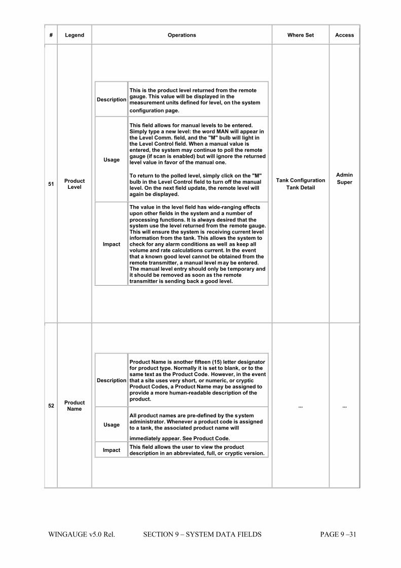
7/16/2019 3900 Manual
http://slidepdf.com/reader/full/3900-manual 251/266
WINGAUGE v5.0 Rel. SECTION 9 – SYSTEM DATA FIELDS PAGE 9 –31
# Legend Operations Where Set Access
51 ProductLevel
Description This is the product level returned from the remotegauge. This value will be displayed in themeasurement units defined for level, on the system
configuration page.
Usage
This field allows for manual levels to be entered.Simply type a new level: the word MAN will appear inthe Level Comm. field, and the "M" bulb will light inthe Level Control field. When a manual value isentered, the system may continue to poll the remotegauge (if scan is enabled) but will ignore the returnedlevel value in favor of the manual one.
To return to the polled level, simply click on the "M"bulb in the Level Control field to turn off the manuallevel. On the next field update, the remote level willagain be displayed.
Impact
The value in the level field has wide-ranging effectsupon other fields in the system and a number of
processing functions. It is always desired that thesystem use the level returned from the remote gauge.This will ensure the system is receiving current levelinformation from the tank. This allows the system tocheck for any alarm conditions as well as keep allvolume and rate calculations current. In the eventthat a known good level cannot be obtained from theremote transmitter, a manual level may be entered.The manual level entry should only be temporary andit should be removed as soon as the remotetransmitter is sending back a good level.
Tank Configuration Tank Detail
Admin
Super
52 ProductName
Description
Product Name is another fifteen (15) letter designator for product type. Normally it is set to blank, or to thesame text as the Product Code. However, in the eventthat a site uses very short, or numeric, or crypticProduct Codes, a Product Name may be assigned toprovide a more human-readable description of theproduct.
Usage All product names are pre-defined by the systemadministrator. Whenever a product code is assignedto a tank, the associated product name will
immediately appear. See Product Code. Impact This field allows the user to view the product
description in an abbreviated, full, or cryptic version.
... ...
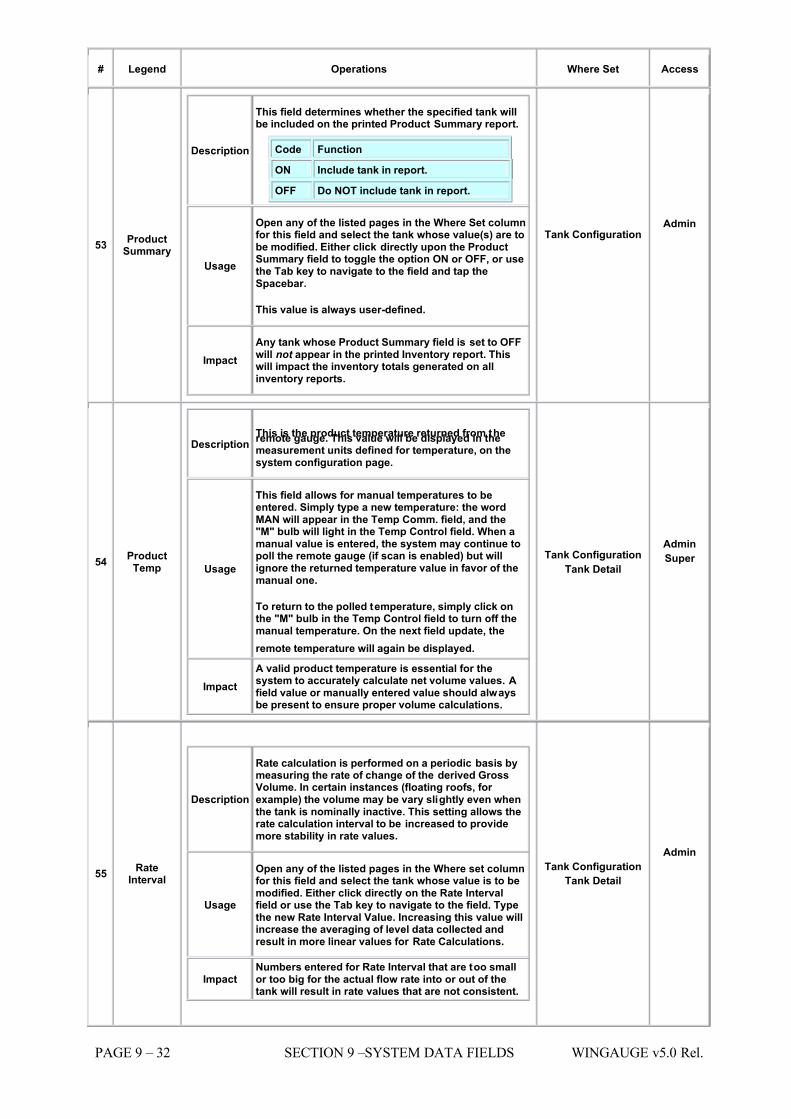
7/16/2019 3900 Manual
http://slidepdf.com/reader/full/3900-manual 252/266
PAGE 9 – 32 SECTION 9 –SYSTEM DATA FIELDS WINGAUGE v5.0 Rel.
# Legend Operations Where Set Access
53 ProductSummary
Description
This field determines whether the specified tank willbe included on the printed Product Summary report.
Code Function
ON Include tank in report.
OFF Do NOT include tank in report.
Usage
Open any of the listed pages in the Where Set columnfor this field and select the tank whose value(s) are tobe modified. Either click directly upon the ProductSummary field to toggle the option ON or OFF, or usethe Tab key to navigate to the field and tap theSpacebar.
This value is always user-defined.
Impact Any tank whose Product Summary field is set to OFFwill not appear in the printed Inventory report. Thiswill impact the inventory totals generated on allinventory reports.
Tank Configuration Admin
54 ProductTemp
Description This is the product temperature returned from theremote gauge. This value will be displayed in themeasurement units defined for temperature, on thesystem configuration page.
Usage
This field allows for manual temperatures to beentered. Simply type a new temperature: the wordMAN will appear in the Temp Comm. field, and the"M" bulb will light in the Temp Control field. When amanual value is entered, the system may continue topoll the remote gauge (if scan is enabled) but willignore the returned temperature value in favor of themanual one.
To return to the polled temperature, simply click onthe "M" bulb in the Temp Control field to turn off themanual temperature. On the next field update, the
remote temperature will again be displayed.
Impact A valid product temperature is essential for thesystem to accurately calculate net volume values. Afield value or manually entered value should alwaysbe present to ensure proper volume calculations.
Tank Configuration Tank Detail
Admin
Super
55 RateInterval
Description
Rate calculation is performed on a periodic basis bymeasuring the rate of change of the derived GrossVolume. In certain instances (floating roofs, for example) the volume may be vary slightly even whenthe tank is nominally inactive. This setting allows therate calculation interval to be increased to providemore stability in rate values.
Usage
Open any of the listed pages in the Where set columnfor this field and select the tank whose value is to bemodified. Either click directly on the Rate Intervalfield or use the Tab key to navigate to the field. Typethe new Rate Interval Value. Increasing this value willincrease the averaging of level data collected andresult in more linear values for Rate Calculations.
Impact Numbers entered for Rate Interval that are too smallor too big for the actual flow rate into or out of thetank will result in rate values that are not consistent.
Tank Configuration Tank Detail
Admin
7/16/2019 3900 Manual
http://slidepdf.com/reader/full/3900-manual 253/266
WINGAUGE v5.0 Rel. SECTION 9 – SYSTEM DATA FIELDS PAGE 9 –33
# Legend Operations Where Set Access
56 Roof API
Description
Roof Correction: A correction factor for volumecalculations based on the amount of productdisplaced by a floating roof. It is a function of roof shape, roof weight and 60 degree API gravity of theproduct in the tank.
Usage
Open any of the listed pages in the Where set columnfor this field and select the tank whose value is to be
modified. Either click directly on the Roof API field or use the tab key to navigate to teh field. Type the newRoof API value. The value is entered in the systemunits chosen for API.
Impact The roof API should only be used when roof correction is desired for Net Volume calculations. Itshould be set to zero if no roof correction of NetVolume is desired.
Tank Configuration Admin
57 StrappingTable
Description This field selects the strapping table to be used toprovide level-to-volume conversions. This value must be set to a strapping table appropriate for theparticular tank, or volume readings will be incorrect.
Usage
Open any of the pages listed in the where set columnfor this field and select the tank whose value is to bemodified. Either click directly on the Strapping Tablefield or use the tab key to navigate to the field. Typethe new strapping table number.
Impact It is important that the proper strapping table beassigned to each tank. This will allow the system toaccurately calculate all system values based onvolume.
Tank Configuration Admin
58 TankControl
Description This field allows all field scan and alarm evaluationsettings for the selected tank to be enabled or disabled simultaneously.
Usage
The Tank Control field allows the user to toggle thefollowing real-time gauging parameters. There aretwo small light bulbs in this field, each containing aletter code corresponding to the function the bulbcontrols, as follows:
Code Function
S Master Scan
A Master Alarm Evaluation
This field works similarly to the other Control fields,however it does not control a specific data item:rather, it controls whether or not the other itemsperform their functions. For example, if the Master Scan bulb is dark (disabled) none of the other gaugepolling functions will work (level, temp, BS&W,
Density, etc.) This allows a gauge to be totallydeactivated with a single mouse click.
Impact
This setting will potentially stop all scanning of aselected tank for level, temp, etc. Even if level andtemp scan are enabled in their respective fields, thetank control field will still stop the system frompolling the remote transmitter. All alarm evaluationcan be disabled for a tank from the tank Control field.If this is selected, the system will ignore all alarmconditions that may occur and no visual or audiblewarnings will be present in the system. For theselected tank.
Tank Configuration Tank Detail
Admin
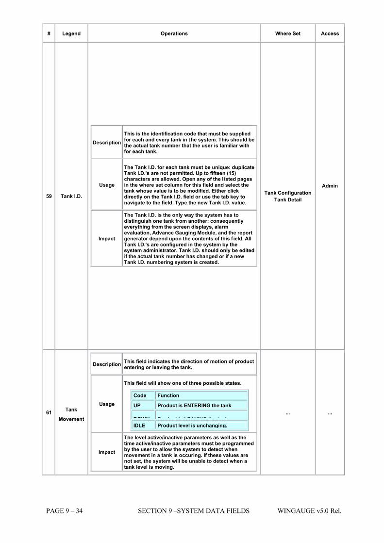
7/16/2019 3900 Manual
http://slidepdf.com/reader/full/3900-manual 254/266
PAGE 9 – 34 SECTION 9 –SYSTEM DATA FIELDS WINGAUGE v5.0 Rel.
# Legend Operations Where Set Access
59 Tank I.D.
Description This is the identification code that must be suppliedfor each and every tank in the system. This should bethe actual tank number that the user is familiar withfor each tank.
Usage
The Tank I.D. for each tank must be unique: duplicateTank I.D.'s are not permitted. Up to fifteen (15)characters are allowed. Open any of the l isted pagesin the where set column for this field and select thetank whose value is to be modified. Either clickdirectly on the Tank I.D. field or use the tab key tonavigate to the field. Type the new Tank I.D. value.
Impact
The Tank I.D. is the only way the system has todistinguish one tank from another: consequentlyeverything from the screen displays, alarmevaluation, Advance Gauging Module, and the reportgenerator depend upon the contents of this f ield. AllTank I.D.'s are configured in the system by thesystem administrator. Tank I.D. should only be editedif the actual tank number has changed or if a newTank I.D. numbering system is created.
Tank Configuration Tank Detail
Admin
61 Tank
Movement
Description This field indicates the direction of motion of productentering or leaving the tank.
Usage
This field will show one of three possible states.
Code Function
UP Product is ENTERING the tank
DOWN Product is LEAVING the tank. IDLE Product level is unchanging.
Impact
The level active/inactive parameters as well as thetime active/inactive parameters must be programmedby the user to allow the system to detect whenmovement in a tank is occuring. If these values arenot set, the system will be unable to detect when atank level is moving.
... ...
7/16/2019 3900 Manual
http://slidepdf.com/reader/full/3900-manual 255/266
WINGAUGE v5.0 Rel. SECTION 9 – SYSTEM DATA FIELDS PAGE 9 –35
# Legend Operations Where Set Access
62 TankSummary
Description
This field determines whether the specified tank willbe included on the printed Tank Summary report.
Code Function
ON Include tank in report. OFF Do NOT include tank in report.
Usage
Open any of the listed pages in the Where Set columnfor this field and select the tank whose value(s) are tobe modified. Either click directly upon the TankSummary field to toggle the option ON or OFF, or usethe Tab key to navigate to the field and tap theSpacebar.
This value is always user-defined.
Impact Any tank whose Tank Summary field is set to OFF willnot appear in the printed Inventory report.
Tank Configuration Admin
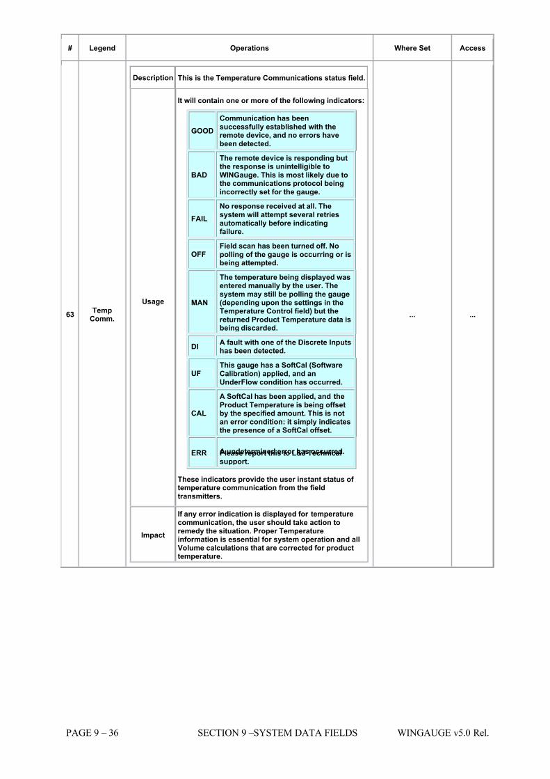
7/16/2019 3900 Manual
http://slidepdf.com/reader/full/3900-manual 256/266
PAGE 9 – 36 SECTION 9 –SYSTEM DATA FIELDS WINGAUGE v5.0 Rel.
# Legend Operations Where Set Access
63 TempComm.
Description This is the Temperature Communications status field.
Usage
It will contain one or more of the following indicators:
GOOD Communication has beensuccessfully established with theremote device, and no errors havebeen detected.
BAD
The remote device is responding butthe response is unintelligible toWINGauge. This is most likely due tothe communications protocol beingincorrectly set for the gauge.
FAIL No response received at all. Thesystem will attempt several retriesautomatically before indicatingfailure.
OFF Field scan has been turned off. Nopolling of the gauge is occurring or isbeing attempted.
MAN
The temperature being displayed wasentered manually by the user. Thesystem may still be polling the gauge(depending upon the settings in theTemperature Control field) but thereturned Product Temperature data isbeing discarded.
DI A fault with one of the Discrete Inputshas been detected.
UF This gauge has a SoftCal (SoftwareCalibration) applied, and anUnderFlow condition has occurred.
CAL
A SoftCal has been applied, and theProduct Temperature is being offsetby the specified amount. This is notan error condition: it simply indicatesthe presence of a SoftCal offset.
ERR A undetermined error has occurred.Please report this to L&J Technicalsupport.
These indicators provide the user instant status of temperature communication from the fieldtransmitters.
Impact
If any error indication is displayed for temperaturecommunication, the user should take action toremedy the situation. Proper Temperatureinformation is essential for system operation and allVolume calculations that are corrected for producttemperature.
... ...
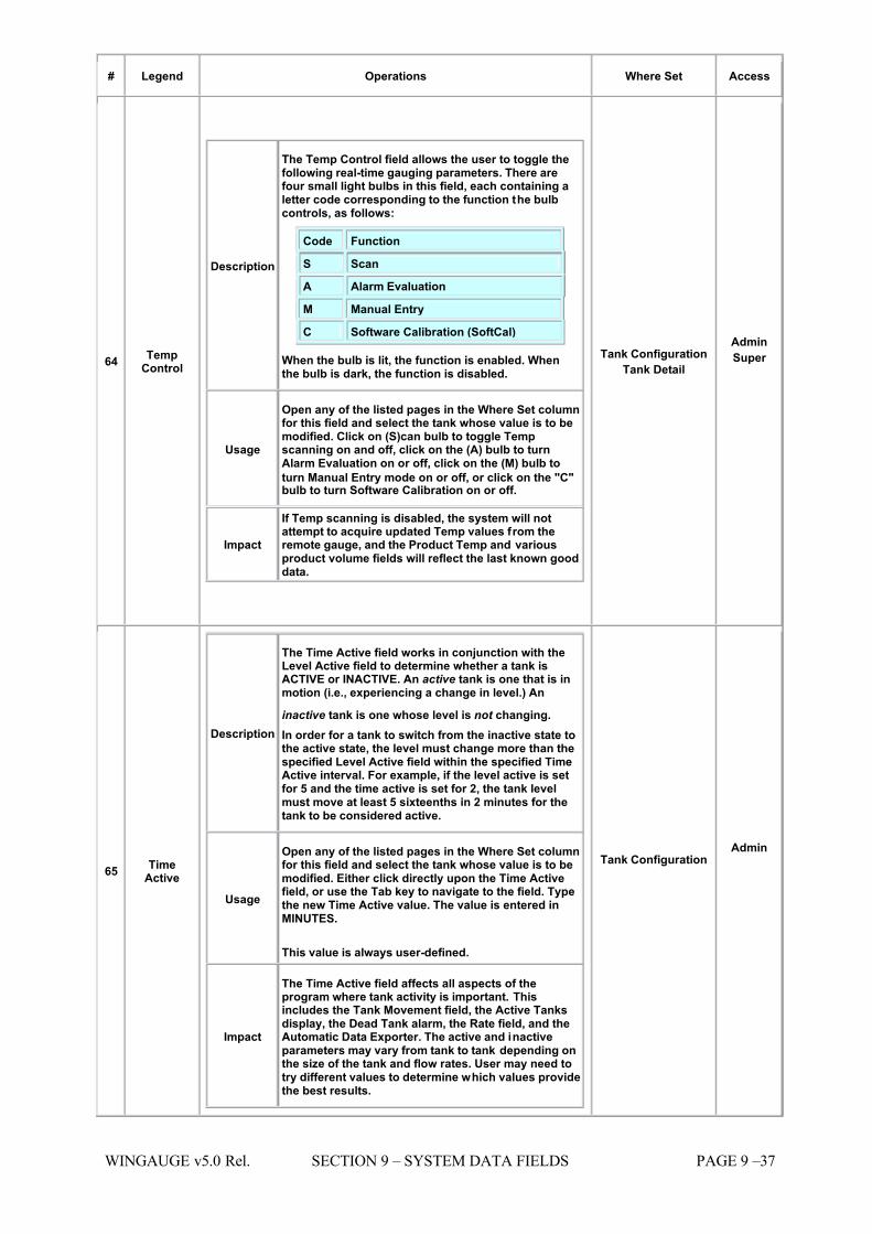
7/16/2019 3900 Manual
http://slidepdf.com/reader/full/3900-manual 257/266
WINGAUGE v5.0 Rel. SECTION 9 – SYSTEM DATA FIELDS PAGE 9 –37
# Legend Operations Where Set Access
64 TempControl
Description
The Temp Control field allows the user to toggle thefollowing real-time gauging parameters. There arefour small light bulbs in this field, each containing aletter code corresponding to the function the bulbcontrols, as follows:
Code Function S Scan
A Alarm Evaluation
M Manual Entry
C Software Calibration (SoftCal)
When the bulb is lit, the function is enabled. Whenthe bulb is dark, the function is disabled.
Usage
Open any of the listed pages in the Where Set columnfor this field and select the tank whose value is to bemodified. Click on (S)can bulb to toggle Tempscanning on and off, click on the (A) bulb to turnAlarm Evaluation on or off, click on the (M) bulb to
turn Manual Entry mode on or off, or click on the "C"bulb to turn Software Calibration on or off.
Impact
If Temp scanning is disabled, the system will notattempt to acquire updated Temp values from theremote gauge, and the Product Temp and variousproduct volume fields will reflect the last known gooddata.
Tank Configuration Tank Detail
Admin
Super
65 TimeActive
Description
The Time Active field works in conjunction with theLevel Active field to determine whether a tank isACTIVE or INACTIVE. An active tank is one that is inmotion (i.e., experiencing a change in level.) An
inactive tank is one whose level is not changing. In order for a tank to switch from the inactive state tothe active state, the level must change more than thespecified Level Active field within the specified TimeActive interval. For example, if the level active is setfor 5 and the time active is set for 2, the tank levelmust move at least 5 sixteenths in 2 minutes for thetank to be considered active.
Usage
Open any of the listed pages in the Where Set columnfor this field and select the tank whose value is to bemodified. Either click directly upon the Time Activefield, or use the Tab key to navigate to the field. Typethe new Time Active value. The value is entered inMINUTES.
This value is always user-defined.
Impact
The Time Active field affects all aspects of theprogram where tank activity is important. Thisincludes the Tank Movement field, the Active Tanksdisplay, the Dead Tank alarm, the Rate field, and theAutomatic Data Exporter. The active and inactiveparameters may vary from tank to tank depending onthe size of the tank and flow rates. User may need totry different values to determine which values providethe best results.
Tank Configuration Admin
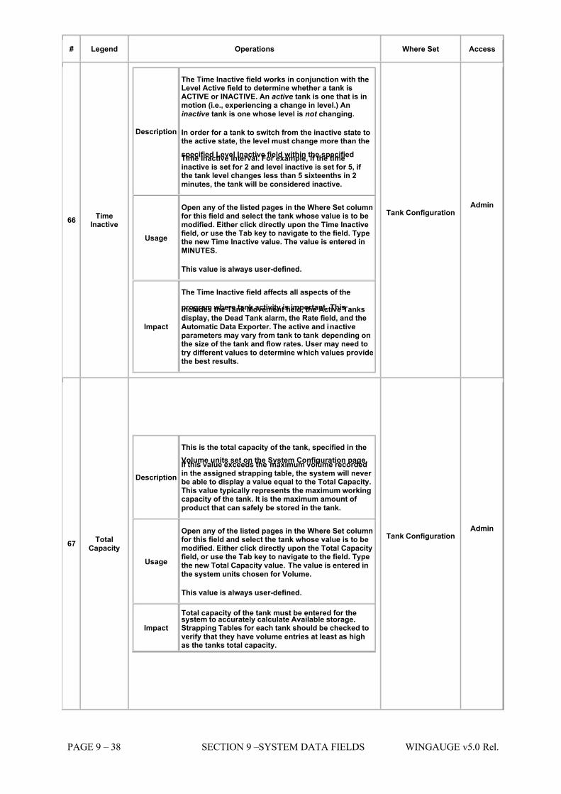
7/16/2019 3900 Manual
http://slidepdf.com/reader/full/3900-manual 258/266
PAGE 9 – 38 SECTION 9 –SYSTEM DATA FIELDS WINGAUGE v5.0 Rel.
# Legend Operations Where Set Access
66 TimeInactive
Description
The Time Inactive field works in conjunction with theLevel Active field to determine whether a tank isACTIVE or INACTIVE. An active tank is one that is inmotion (i.e., experiencing a change in level.) Aninactive tank is one whose level is not changing.
In order for a tank to switch from the inactive state tothe active state, the level must change more than the
specified Level Inactive field within the specifiedTime Inactive interval. For example, if the timeinactive is set for 2 and level inactive is set for 5, if the tank level changes less than 5 sixteenths in 2minutes, the tank will be considered inactive.
Usage
Open any of the listed pages in the Where Set columnfor this field and select the tank whose value is to bemodified. Either click directly upon the Time Inactivefield, or use the Tab key to navigate to the field. Typethe new Time Inactive value. The value is entered in
MINUTES.
This value is always user-defined.
Impact
The Time Inactive field affects all aspects of the
program where tank activity is important. Thisincludes the Tank Movement field, the Active Tanksdisplay, the Dead Tank alarm, the Rate field, and theAutomatic Data Exporter. The active and inactiveparameters may vary from tank to tank depending onthe size of the tank and flow rates. User may need totry different values to determine which values providethe best results.
Tank Configuration Admin
67 TotalCapacity
Description
This is the total capacity of the tank, specified in the
Volume units set on the System Configuration page.If this value exceeds the maximum volume recordedin the assigned strapping table, the system will never be able to display a value equal to the Total Capacity.This value typically represents the maximum workingcapacity of the tank. It is the maximum amount of
product that can safely be stored in the tank.
Usage
Open any of the listed pages in the Where Set columnfor this field and select the tank whose value is to bemodified. Either click directly upon the Total Capacityfield, or use the Tab key to navigate to the field. Typethe new Total Capacity value. The value is entered inthe system units chosen for Volume.
This value is always user-defined.
Impact
Total capacity of the tank must be entered for thesystem to accurately calculate Available storage.Strapping Tables for each tank should be checked toverify that they have volume entries at least as highas the tanks total capacity.
Tank Configuration Admin
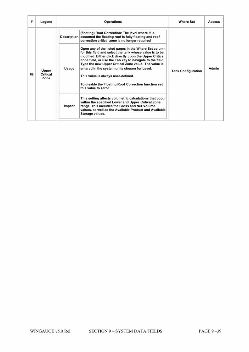
7/16/2019 3900 Manual
http://slidepdf.com/reader/full/3900-manual 259/266
WINGAUGE v5.0 Rel. SECTION 9 – SYSTEM DATA FIELDS PAGE 9 –39
# Legend Operations Where Set Access
68 Upper CriticalZone
Description (floating) Roof Correction: The level where it isassumed the floating roof is fully floating and roof correction critical zone is no longer required
Usage
Open any of the listed pages in the Where Set columnfor this field and select the tank whose value is to bemodified. Either click directly upon the Upper CriticalZone field, or use the Tab key to navigate to the field.Type the new Upper Critical Zone value. The value is
entered in the system units chosen for Level.
This value is always user-defined.
To disable the Floating Roof Correction function setthis value to zero!
Impact
This setting affects volumetric calculations that occur within the specified Lower and Upper Critical Zonerange. This includes the Gross and Net Volumevalues, as well as the Available Product and AvailableStorage values.
Tank Configuration Admin
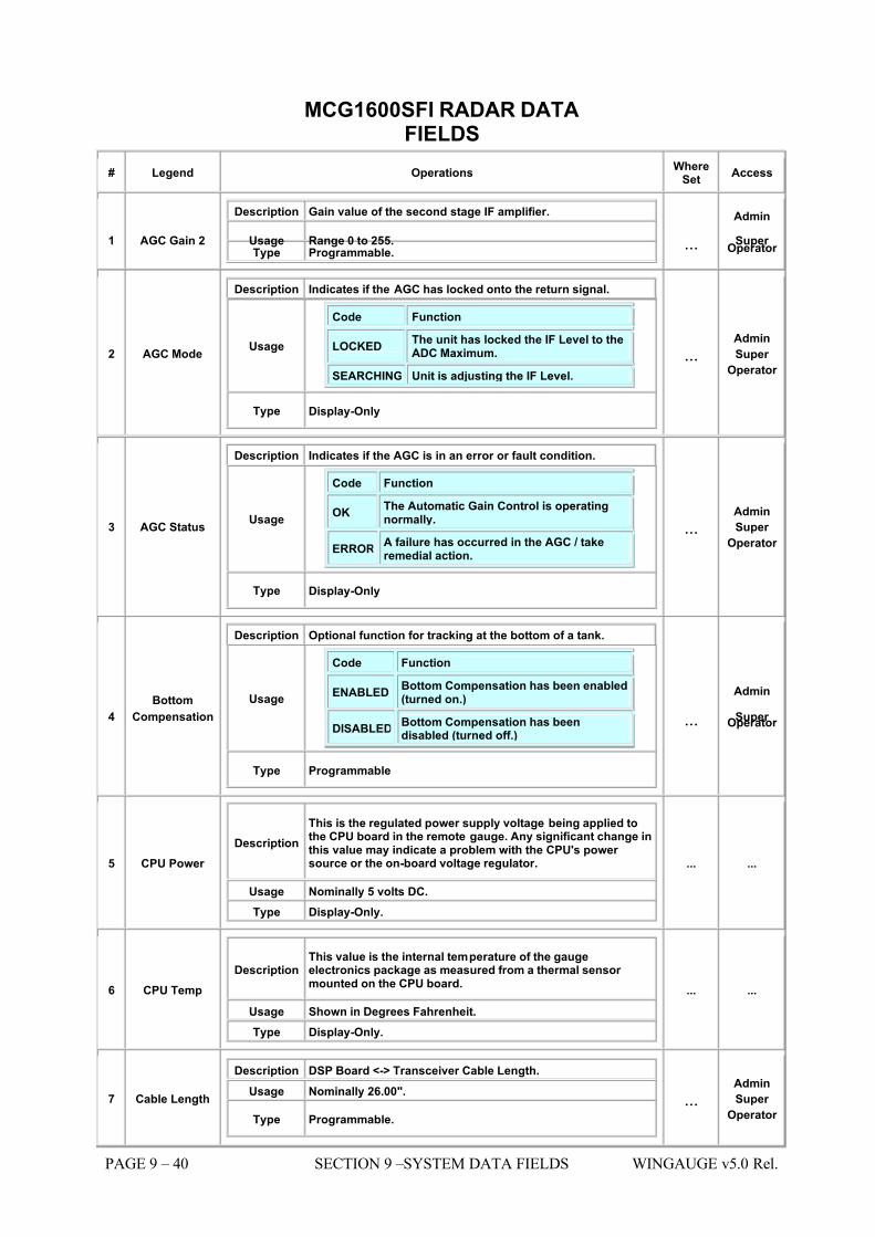
7/16/2019 3900 Manual
http://slidepdf.com/reader/full/3900-manual 260/266
PAGE 9 – 40 SECTION 9 –SYSTEM DATA FIELDS WINGAUGE v5.0 Rel.
MCG1600SFI RADAR DATAFIELDS
# Legend Operations WhereSet
Access
1 AGC Gain 2
Description Gain value of the second stage IF amplifier.
Usage Range 0 to 255. Type Programmable. ...
Admin
Super Operator
2 AGC Mode
Description Indicates if the AGC has locked onto the return signal.
Usage
Code Function
LOCKED The unit has locked the IF Level to theADC Maximum.
SEARCHING Unit is adjusting the IF Level.
Type Display-Only
...Admin
Super
Operator
3 AGC Status
Description Indicates if the AGC is in an error or fault condition.
Usage
Code Function
OK The Automatic Gain Control is operatingnormally.
ERRORA failure has occurred in the AGC / takeremedial action.
Type Display-Only
...Admin
Super
Operator
4 Bottom
Compensation
Description Optional function for tracking at the bottom of a tank.
Usage
Code Function
ENABLEDBottom Compensation has been enabled(turned on.)
DISABLEDBottom Compensation has beendisabled (turned off.)
Type Programmable
...
Admin
Super Operator
5 CPU Power Description
This is the regulated power supply voltage being applied tothe CPU board in the remote gauge. Any significant change inthis value may indicate a problem with the CPU's power source or the on-board voltage regulator.
Usage Nominally 5 volts DC. Type Display-Only.
... ...
6 CPU Temp Description
This value is the internal temperature of the gaugeelectronics package as measured from a thermal sensor mounted on the CPU board.
Usage Shown in Degrees Fahrenheit. Type Display-Only.
... ...
7 Cable Length
Description DSP Board <-> Transceiver Cable Length. Usage Nominally 26.00".
Type Programmable. ...
Admin
Super
Operator
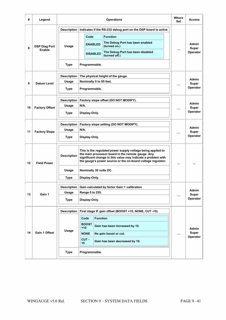
7/16/2019 3900 Manual
http://slidepdf.com/reader/full/3900-manual 261/266
WINGAUGE v5.0 Rel. SECTION 9 – SYSTEM DATA FIELDS PAGE 9 –41
# Legend Operations WhereSet
Access
8 DSP Diag PortEnable
Description Indicates if the RS-232 debug port on the DSP board is active
Usage
Code Function
ENABLEDThe Debug Port has been enabled(turned on.)
DISABLEDThe Debug Port has been disabled(turned off.)
Type Programmable.
...Admin
Super
Operator
9 Datum Level
Description The physical height of the gauge. Usage Nominally 0 to 95 feet.
Type Programmable. ...
Admin
Super
Operator
10 Factory Offset
Description Factory slope offset (DO NOT MODIFY). Usage N/A.
Type Display-Only. ...
Admin
Super
Operator
11 Factory Slope
Description Factory slope setting (DO NOT MODIFY). Usage N/A.
Type Display-Only. ...
Admin
Super
Operator
12 Field Power
Description This is the regulated power supply voltage being applied tothe main processor board in the remote gauge. Anysignificant change in this value may indicate a problem withthe gauge's power source or the on-board voltage regulator.
Usage Nominally 30 volts DC.
Type Display-Only.
... ...
13 Gain 1
Description Gain calculated by factor Gain 1 calibration Usage Range 0 to 255.
Type Display-Only. ...
Admin
Super
Operator
14 Gain 1 Offset
Description First stage IF gain offset (BOOST +10, NONE, CUT -10).
Usage
Code Function
BOOST+10
Gain has been increased by 10.
NONE No gain boost or cut.
CUT -10
Gain has been decreased by 10.
Type Programmable.
...Admin
Super
Operator
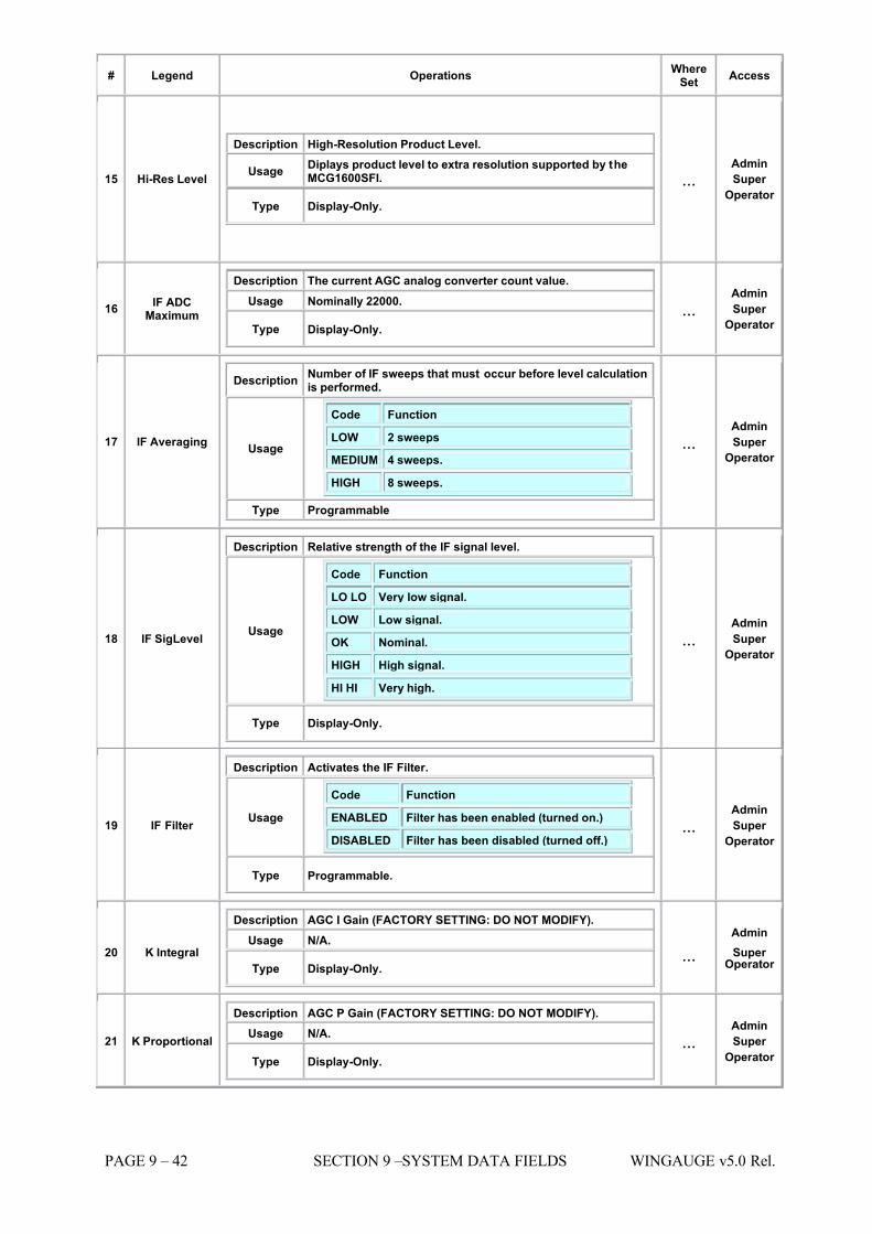
7/16/2019 3900 Manual
http://slidepdf.com/reader/full/3900-manual 262/266
PAGE 9 – 42 SECTION 9 –SYSTEM DATA FIELDS WINGAUGE v5.0 Rel.
# Legend Operations WhereSet
Access
15 Hi-Res Level
Description High-Resolution Product Level.
Usage Diplays product level to extra resolution supported by theMCG1600SFI.
Type Display-Only.
...Admin
Super
Operator
16 IF ADCMaximum
Description The current AGC analog converter count value. Usage Nominally 22000.
Type Display-Only. ...
Admin
Super
Operator
17 IF Averaging
Description Number of IF sweeps that must occur before level calculationis performed.
Usage
Code Function
LOW 2 sweeps
MEDIUM 4 sweeps.
HIGH 8 sweeps.
Type Programmable
...Admin
Super
Operator
18 IF SigLevel
Description Relative strength of the IF signal level.
Usage
Code Function
LO LO Very low signal.
LOW Low signal.
OK Nominal.
HIGH High signal.
HI HI Very high.
Type Display-Only.
...Admin
Super
Operator
19 IF Filter
Description Activates the IF Filter.
Usage
Code Function
ENABLED Filter has been enabled (turned on.)
DISABLED Filter has been disabled (turned off.)
Type Programmable.
...Admin
Super
Operator
20 K Integral
Description AGC I Gain (FACTORY SETTING: DO NOT MODIFY). Usage
N/A.
Type Display-Only.
...
Admin
Super Operator
21 K Proportional
Description AGC P Gain (FACTORY SETTING: DO NOT MODIFY). Usage N/A.
Type Display-Only. ...
Admin
Super
Operator
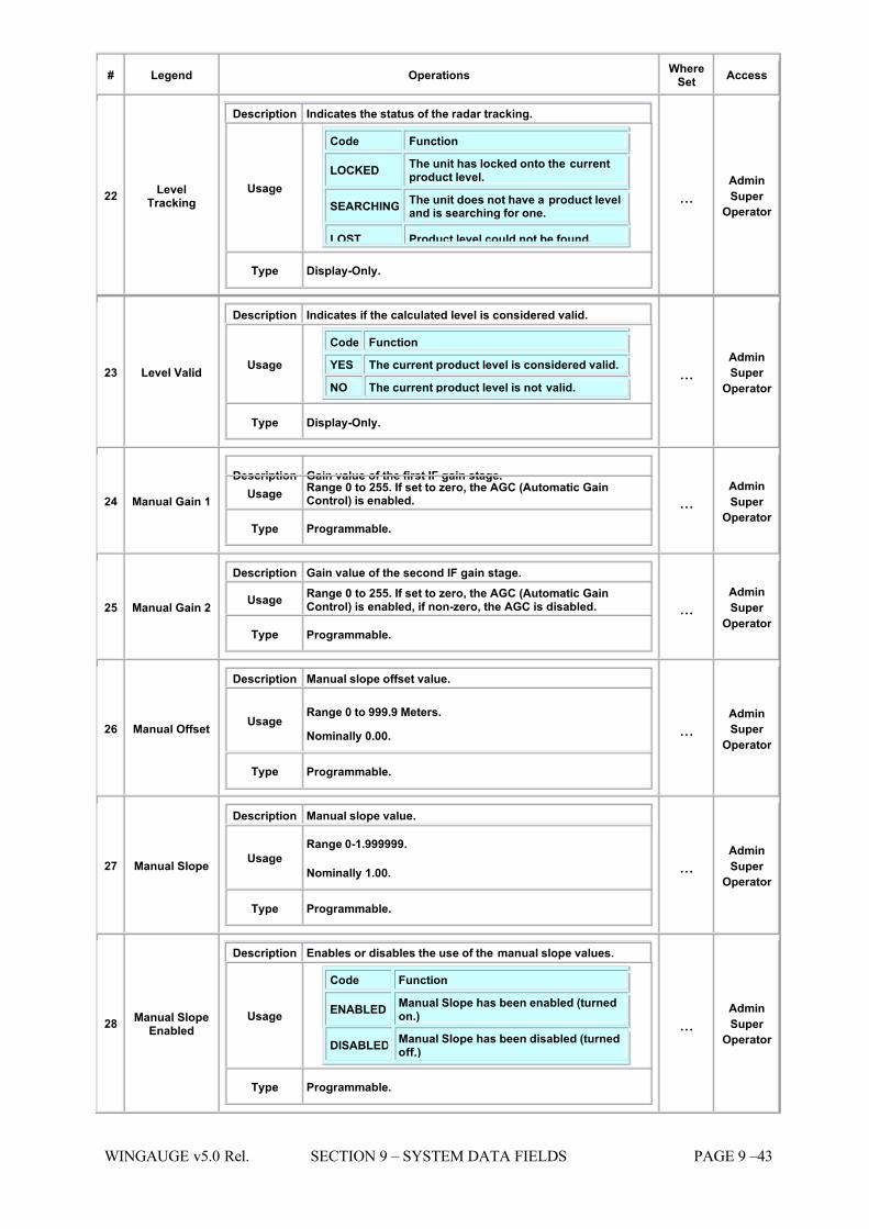
7/16/2019 3900 Manual
http://slidepdf.com/reader/full/3900-manual 263/266
WINGAUGE v5.0 Rel. SECTION 9 – SYSTEM DATA FIELDS PAGE 9 –43
# Legend Operations WhereSet
Access
22 LevelTracking
Description Indicates the status of the radar tracking.
Usage
Code Function
LOCKED The unit has locked onto the currentproduct level.
SEARCHINGThe unit does not have a product leveland is searching for one.
LOST Product level could not be found.
Type Display-Only.
...Admin
Super
Operator
23 Level Valid
Description Indicates if the calculated level is considered valid.
Usage
Code Function
YES The current product level is considered valid.
NO The current product level is not valid.
Type Display-Only.
...Admin
Super
Operator
24 Manual Gain 1
Description Gain value of the first IF gain stage. Usage Range 0 to 255. If set to zero, the AGC (Automatic Gain
Control) is enabled.
Type Programmable.
...Admin
Super
Operator
25 Manual Gain 2
Description Gain value of the second IF gain stage.
Usage Range 0 to 255. If set to zero, the AGC (Automatic GainControl) is enabled, if non-zero, the AGC is disabled.
Type Programmable.
...Admin
Super
Operator
26 Manual Offset
Description Manual slope offset value.
Usage Range 0 to 999.9 Meters. Nominally 0.00.
Type Programmable.
...Admin
Super
Operator
27 Manual Slope
Description Manual slope value.
Usage Range 0-1.999999.
Nominally 1.00.
Type Programmable.
...Admin
Super
Operator
28 Manual SlopeEnabled
Description Enables or disables the use of the manual slope values.
Usage
Code Function
ENABLEDManual Slope has been enabled (turnedon.)
DISABLEDManual Slope has been disabled (turnedoff.)
Type Programmable.
...Admin
Super
Operator
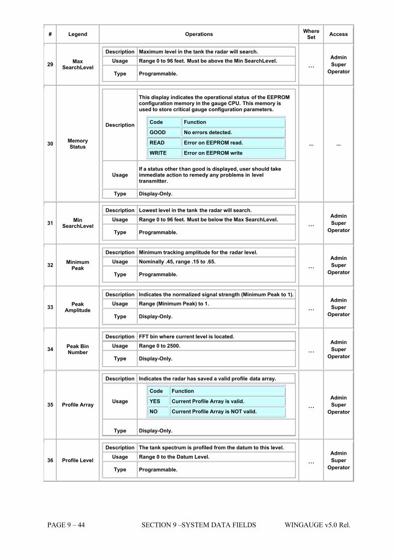
7/16/2019 3900 Manual
http://slidepdf.com/reader/full/3900-manual 264/266
PAGE 9 – 44 SECTION 9 –SYSTEM DATA FIELDS WINGAUGE v5.0 Rel.
# Legend Operations WhereSet
Access
29 MaxSearchLevel
Description Maximum level in the tank the radar will search. Usage Range 0 to 96 feet. Must be above the Min SearchLevel.
Type Programmable. ...
Admin
Super
Operator
30 MemoryStatus
Description
This display indicates the operational status of the EEPROMconfiguration memory in the gauge CPU. This memory isused to store critical gauge configuration parameters.
Code Function
GOOD No errors detected.
READ Error on EEPROM read.
WRITE Error on EEPROM write
Usage If a status other than good is displayed, user should takeimmediate action to remedy any problems in leveltransmitter.
Type Display-Only.
... ...
31 MinSearchLevel
Description
Lowest level in the tank the radar will search.
Usage Range 0 to 96 feet. Must be below the Max SearchLevel.
Type Programmable. ...
Admin
Super
Operator
32 MinimumPeak
Description Minimum tracking amplitude for the radar level. Usage Nominally .45, range .15 to .65.
Type Programmable. ...
Admin
Super
Operator
33 PeakAmplitude
Description Indicates the normalized signal strength (Minimum Peak to 1). Usage Range (Minimum Peak) to 1.
Type Display-Only. ...
Admin
Super
Operator
34 Peak BinNumber
Description FFT bin where current level is located. Usage Range 0 to 2500.
Type Display-Only. ...
Admin
Super
Operator
35 Profile Array
Description Indicates the radar has saved a valid profile data array.
Usage
Code Function
YES Current Profile Array is valid.
NO Current Profile Array is NOT valid.
Type Display-Only.
...Admin
Super
Operator
36 Profile Level
Description The tank spectrum is profiled from the datum to this level. Usage Range 0 to the Datum Level.
Type Programmable. ...
Admin
Super
Operator
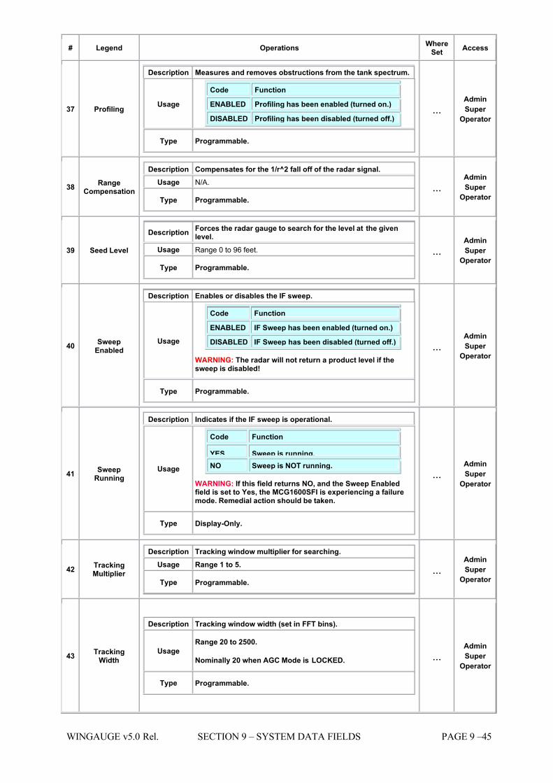
7/16/2019 3900 Manual
http://slidepdf.com/reader/full/3900-manual 265/266
WINGAUGE v5.0 Rel. SECTION 9 – SYSTEM DATA FIELDS PAGE 9 –45
# Legend Operations WhereSet
Access
37 Profiling
Description Measures and removes obstructions from the tank spectrum.
Usage
Code Function
ENABLED Profiling has been enabled (turned on.)
DISABLED Profiling has been disabled (turned off.)
Type Programmable.
...Admin
Super
Operator
38 RangeCompensation
Description Compensates for the 1/r^2 fall off of the radar signal. Usage N/A.
Type Programmable. ...
Admin
Super
Operator
39 Seed Level
Description Forces the radar gauge to search for the level at the givenlevel.
Usage Range 0 to 96 feet.
Type Programmable.
...Admin
Super
Operator
40 SweepEnabled
Description
Enables or disables the IF sweep.
Usage
Code Function
ENABLED IF Sweep has been enabled (turned on.)
DISABLED IF Sweep has been disabled (turned off.)
WARNING: The radar will not return a product level if thesweep is disabled!
Type Programmable.
...Admin
Super
Operator
41 SweepRunning
Description Indicates if the IF sweep is operational.
Usage
Code Function
YES Sweep is running. NO Sweep is NOT running.
WARNING: If this field returns NO, and the Sweep Enabledfield is set to Yes, the MCG1600SFI is experiencing a failuremode. Remedial action should be taken.
Type Display-Only.
...Admin
Super
Operator
42 TrackingMultiplier
Description Tracking window multiplier for searching. Usage Range 1 to 5.
Type Programmable. ...
Admin
Super
Operator
43 TrackingWidth
Description Tracking window width (set in FFT bins).
Usage Range 20 to 2500.
Nominally 20 when AGC Mode is LOCKED.
Type Programmable.
...Admin
Super
Operator

7/16/2019 3900 Manual
http://slidepdf.com/reader/full/3900-manual 266/266
# Legend Operations WhereSet
Access
44 Transceiver IF
Description The Transceiver Intermediate Frequency. Usage Range 135 Hz. to 3093 Hz.
Type Display-Only. ...
Admin
Super
Operator
Description Transceiver power supply voltage.