Embed Size (px)
Citation preview

FINAL 3.9 GEOLOGY AND SOILS
AUGUST 2008 3.9-1
3.9 Geology and Soils 3.9.1 Existing Conditions The Lompoc Wind Energy Project (Project) is located within one of the most complex geologic settings in North America. The regional forces exerted by plate tectonics and the resulting intersection of two of California’s primary geomorphic provinces provide for highly variable landforms and unique geologic conditions. This section describes the regional geologic and physiographic setting, Project area geology and geomorphology, soils, erosion potential, and the hazards associated with them.
The geology of the area in and surrounding the Project has been extensively described by previous authors. The information provided in this section represents a summary of their work and does not intend to represent any material as new or updated. Previous descriptions by these authors and references of the geologic setting, geologic history, and geologic structure in the vicinity of the Project are both detailed and sufficient to adequately describe conditions and assess potential Project impacts.
3.9.1.1 Regional Geology and Physiography Most mountain ranges in North America and California follow a north-south trend as part of “The Western Cordillera.” The unique orientation of the Transverse Ranges (east-west) is attributed to plate interaction and the orientation of the San Andreas fault as it enters the Transverse Range geomorphic province (Norris, 2003). The San Andreas Fault veers west as it enters this province, creating the “Big Bend.” This results in crustal shortening and the development of an east-west belt of mountains and valleys. Figure 3.9-1 shows geology within the Project area.
Primary physiographic features in the vicinity of the Project include mountains, hills, valleys, mesas, and terraces. The mountains of the lower Santa Ynez Range (westward extension of the Santa Ynez Mountains) represent the transverse ranges from Gaviota on the east to Points Arguello and Pedernales on the west. The Project area is situated west of the Lompoc Hills and is bounded on the north by the Lompoc Valley. This area includes sedimentary and volcanic deposits, and while this area is geologically young, the landforms are mature relative to areas within the range to the east. Regionally, these hills are part of a southward dipping homocline with minor local structural features (synclines/anticlines) superimposed (Dibblee, 1950).
The Project area has been subject to at least two erosion cycles, contributing to the “mature” nature of the landforms (Dibblee, 1950). Erosion took place during both middle and late Pleistocene. The first cycle resulted in filling of the synclinal trough in the Santa Ynez and Lompoc Valleys (north of the Project area). Late Pleistocene erosion removed remnant upper Pliocene (such as Careaga Formation) and terrestrial Pleistocene deposits (such as Paso Robles and Orcutt Formations), and further exposed Miocene and older deposits.
The Project is located within the Santa Ynez Mountain Range, which is made up of a very thick Cretaceous-Tertiary sedimentary section uplifted along the Santa Ynez fault (Dibblee, 1950). Most fold axes and the strike of many faults are slightly north of west due to crustal shortening perpendicular to this orientation (north-northeast/south-southwest). Regionally,

3.9 GEOLOGY AND SOILS FINAL
3.9-2 AUGUST 2008
the Santa Ynez Mountains can be subdivided into both Southern and Northern structural blocks (Dibblee, 1950). Those formations lying north of the Santa Ynez-Pacifico fault zone are part of the Northern structural block. The Project is located within this structural block, and is composed of a southward-dipping homocline with a stratigraphic section that includes Cretaceous through Tertiary sediments and Quaternary alluvium and landforms (such as landslides). The stratigraphic sequence in the Northern block is considerably thinner than that of the Southern block, and is dominated by numerous minor folds trending N. 75° W., developed in the Miocene formations. These minor folds are superimposed on the regional southward dipping older formations of the homocline.
The regional fault system is active and is largely responsible for historic and ongoing uplift of the Santa Ynez Mountains. The south side of the fault is upthrown, and total throw amounts to several miles (Dibblee, 1950). West of Gaviota (western Santa Ynez Mountains), the Santa Ynez fault divides into several faults, including the locally significant Pacifico fault. The geologic formations within the Project area are shown on Figure 3.9-1.
Fault interactions related to the convergence of the Coast and Transverse Ranges geomorphic provinces resulted in the development of the “Salinian Block.” The Salinian Block is a section of igneous intrusive (for example, granitic) rocks between sections of Franciscan formation basement. This block of igneous rocks occurs between the northwest-trending San Andreas and Sur-Naciemento-Rinconada fault zones (Norris, 2003). The faults within the Project area are shown on Figure 3.9-2.
3.9.1.2 Project Area Geologic Units Geologic units in the vicinity of the Project area include rocks from the Jurassic through Quaternary (recent) ages. Quaternary deposits and landforms represent recent conditions and are developed as uplift in the Santa Ynez Mountains and structural shortening (compression) of geologic units continues. Geologic units in the vicinity of the Project are shown on Figure 3.9-1 and described in greater detail in this section.
The geologic history of the region includes the following major events (Dibblee, 1950):
• Jurassic Deposition – Deposition of the Franciscan formation under a widespread sea. Deposits in this unit included sands, muds, siliceous cherts, and basaltic lava flows. Deposition of the Honda shale followed deposition of the Franciscan formation.
• Late Jurassic Deformation – Deformation of the Franciscan and Honda formations (brecciation and serpentinized intrusions). The Espada formation is not impacted, indicating that these changes preceded its deposition. This deformation was probably synchronous with the great Nevadan orogeny.
• Late Jurassic-Early Cretaceous Deposition – Marked by continued regional subsidence and deposition of alternating muds and fines sands (the Espada formation). Deposition included abundant plant life.
• Middle Cretaceous Deformation – Changes during this period are speculated, but are not definitively identified in the Espada formation.
• Late Cretaceous Deposition – Subsidence along the Santa Ynez Mountains becomes the northern part of the Santa Barbara Embayment. Over 3,000 feet of muds, silts, and sands

FINAL 3.9 GEOLOGY AND SOILS
AUGUST 2008 3.9-3
(Jamala formation) are deposited. Absence of the Jamala formation north of the Santa Ynez fault indicate that the area was emergent (above sea level) during this period.
• Early Eocene Deformation – Emergence of sediments, uplift, and erosion, associated with the great Laramide orogeny contributed to or caused the unconformity between Cretaceous formations and the Eocene Anita shale.
• Eocene-Oligocene Deposition – Continuous subsidence in the region led to the deposition of a continuous series of sands, silts and clays making up the Anita Matilija, Cozy Dell, Sacate, and Gaviota formations, attaining a total maximum thickness of ~ 7,500 feet.
• Oligocene Deformation – Renewed deformation, uplift, and erosion associated with the Ynezan orogeny led to compression of older formations into gentle folds with axes trending slightly north of west. The Franciscan formation is exposed and becomes the source of Sespe-Vaqueros conglomerates.
• Early Miocene Deposition – Submergence under a shallow sea transgressing northward from the Santa Barbara embayment led to deposition of the coarse gravel, then sand, of the Vaqueros formation, followed by the fine muds of the Rincon formation as the sea deepened.
• Early Miocene Deformation – The Lompocan orogeny caused renewed uplift, deformation, and erosion. Folds developed during the Ynezan orogeny became further compressed. Significantly, local volcanism, regional submergence, and changes in sedimentation followed the Lompocan orogeny.
• Early Micoene Volcanism – Volcanic eruptions of rhyolite lava, agglomerate and ash in the vicinity of Tranquillon Mountain during regional subsidence following the Lompocan orogeny.
• Middle and Late Miocene Deposition – Regional submergence under an historic sea led to deposition of clays. Calcium carbonate was deposited to form the limestone of the lower Monterey formation, and enormous quantities of siliceous sediment were deposited either organically or chemically. Single-celled organisms flourished during this period and their remains make up a large part of the Monterey formation. Organic debris settled to the bottom, was not oxidized, and later was transformed into petroleum and bituminous matter. At least 4,500 feet of Monterey sediments were deposited regionally.
• Late Miocene Deformation – The Rafaelan orogeny contributed to emergence, uplift, and tilting of sediments, particularly in the Santa Maria Basin.
• Late Miocene-Pliocene Deposition – Deposition of the Sisquoc formation (primary source of diatomaceous materials in the area) occurred regionally due to the presence of a shallow sea. The absence of clastic materials indicates that the shallow sea in which it was deposited may have been isolated by an island, peninsula, or submarine ridge.
• Late Pliocene Deformation – The regional Zacan orogeny led to a widespread unconformity in the geologic record. Regional deformation, emergence, and erosion

3.9 GEOLOGY AND SOILS FINAL
3.9-4 AUGUST 2008
associated with this orogeny lead to the development of folds and specifically the anticlinal uplifts prevalent in the area.
• Late Pliocene-Pleistocene Deposition – Submergence of the Santa Maria Basin led to widespread deposition of the Careaga formation, followed by the terrestrial deposits of the Paso Robles formation.
• Pleistocene Deformation – Deformation and uplift associated with the Coast Range orogeny led to further compression of existing folds and the development of structure in recently (geologically) deposited Pliocene sediments during the early phase of this period. A period of relative quiescence was present during the later portion of this period, followed by renewed deformation and uplift in the very late portion of the period and recent time.
Alternating periods of deposition, uplift, deformation, and erosion created the unique geologic environment in the vicinity of the Project. The collision of tectonic forces, transgression and regression of both shallow and deep seas, and unique depositional environments contributed to the development of one of the most complex geologic settings in California.
3.9.1.3 Project Area Geology and Geomorphology Widespread faulting and deformation associated with regional and local tectonism developed complex structural features superimposed on a regional homocline. Landforms in the Project area are mature and reflect the age of the formations and regional forces associated with the convergence of the Coast and Transverse ranges geomorphic provinces. Brief descriptions of geologic units for formations within the Project area are provided in this section. Table 3.9-1 presents a list of the geological formations that have been recognized in the Project area. The list is extensive not only because the sedimentary geology of the area is complex, but also because over the last century or so different studies have applied different names to the same or similar stratigraphic units, as well as occasionally splitting one formation into two or three separate units. For example, terrestrial Pleistocene deposits of the Paso Robles and Orcutt formations (Table 3.9-1) are likely to be named “Quaternary Alluvium (Qa)” or “Older Quaternary Dissected Surficial Deposits (Qoa)” by more recent studies if there is uncertainty whether criteria defining the Paso Robles or Orcutt formations can actually be met by other geological exposures in different areas.
TABLE 3.9-1 Geological Formations That Have Been Recognized in the Project Area
Period or Epoch Formation (Fm.) Additional Synonymy Map Unit
Quaternary (Pleistocene and Holocene)
Paso Robles Fm. Alluvium, Older Dissected Surficial Deposits , and Landslide Deposits are generally contemporaneous
[Qa, Qoa, Qls]
Orcutt Fm.
Pliocene Careaga Fm. Graciosa and Cebada Members of the Careaga Sand
[Tacg, Tcac]
Late Miocene - Pliocene Sisquoc Shale [Tsqd]

FINAL 3.9 GEOLOGY AND SOILS
AUGUST 2008 3.9-5
TABLE 3.9-1 Geological Formations That Have Been Recognized in the Project Area
Period or Epoch Formation (Fm.) Additional Synonymy Map Unit
Miocene Monterey Shale [Tml, Tmls, Tm, and Tmd]
Tranquillon Volcanic Fm.
Monterey Shale Member A
[Ttr], [Tml, Tmls]
Early Miocene Rincon Shale [Tr]
Late Oligocene - Miocene
Vaqueros Sandstone [Tvqcg]
Late Eocene - Oligocene Gaviota Fm.- Sacate Fm. Coldwater Fm. [Tg-sa], [Tsass]
Eocene Cozy Dell Shale [Tcd]
Matilija Sandstone [Tma]
Anita Shale - Juncal Fm. Poppin Fm. [Tan]
Middle Mesozoic to early Tertiary
Franciscan Fm.
Espada Fm. [Fm], [Ka]
Of the geologic formations recognized in the area, the following are present within the Lompoc Wind Energy Facility (LWEF) and the 115-kilovolt power line corridor and are shown on Figure 3.9-1:
• Cozy Dell Shale [Tcd] – This formation is a well-bedded shale. The lower unit consists of well-bedded, but easily weathered gray clay shales with spheroidal fractures. There are occasional interbeds of hard greenish sandstone. Upper unit is the same as the lower except it includes two members of thin-bedded, slightly siliceous harder brown clay shales which weather pale gray. The upper unit locally contains gray limestone and grades upward through thin sandstone interbeds into the overlying Sacate sandstone.
• Gaviota-Sacate Formations [Tg-sa] – These units are gradational, and thus undivided. The Sacate (or “Coldwater”) Formation consists of interbedded sandstone and shale in approximately equal amounts. Sandstone is fine to medium grained, hard, well bedded to massive, highly micaceous, bluish gray when fresh, but weathers to buff. The interbedded shales are gray, well bedded to laminated, and highly micaceous. Thin layers of hard brown conglomerate occur locally, with rounded pebbles of porphyritic igneous rock and some Franciscan red cherts in a hard sandstone matrix. The Gaviota Formation is commonly divided into three members. The lower member is a massive soft gray siltstone. The middle member is light buff, thick-bedded, well-sorted fine- to medium-grained concretionary sandstone. The upper member is gray sandy siltstone with some interbedded fine-grained sandstone.
• Vaqueros Sandstone [Tvqcg] – This formation consists of buff sandstone of marine origin grading downward into greenish-brown fossiliferous, cross-bedded basal conglomerate composed almost entirely of Franciscan Formation debris.

3.9 GEOLOGY AND SOILS FINAL
3.9-6 AUGUST 2008
• Tranquillon Volcanic Formation [Ttr] – A formation consisting of rhyolite, agglomerate, ash, and bentonite. The rhyolite is buff colored, dense to slightly porphyritic, and shows prominent flow structure.
• Monterey Shale (Lower Unit) [Tml, Tmls] – This formation consists of four distinct members including the following:
− Bentonite [Member A], equivalent to Tranquillon volcanics formation
− Soft buff-weathering bedded to massive siltstone, silty siliceous shale, and buff-weathering limestone beds [Member B]
− Hard white limestone and interbedded thin strata of soft diatomaceous shale, with minor amounts of phosphatic shale and laminated siliceous shale [Member C]
− Soft, laminated fissile diatomaceous shales, phosphatic shales with occasional thin limestones and minor porcelaneous and cherty shales [Member D]
•• Monterey Shale (Upper Unit) [Tm, Tmd] – A formation of hard laminated brittle opaline cherty shales grading into younger members containing two distinct members, which include the following:
− Layers of dark chalcedonic chert in western exposures [Member E] and
− Hard laminated brown platy porcelaneous shale which weathers white and carries lenses of chert conglomerate in select localities with abundant diatoms [Member F]
• Sisquoc Shale Formation [Tsqd] – A marine derived formation that is white to cream-white, punky laminated diatomite with some places containing thin ash beds.
• Quaternary Alluvium [Qa] – These are valley and floodplain deposits consisting of unconsolidated clays, silts, sands, and gravels.
• Quaternary Landslide Units [Qls] – These are formations consisting of landslide debris.
In addition, the following geologic units are also found in the general vicinity of the Project area as shown on Figure 3.9-1.
• Franciscan Formation [fm] – sandstone, clay shale, radiolarian chert, and basalt of Upper Jurassic age. This unit is the regional and local basement formation.
• Serpentinite [sp] – Sill-like masses of peridotite or pyroxenite altered to serpentine by hydrothermal action.
• Honda Formation [Kh] – Dark greenish-brown clay shale. This unit may be equivalent to Knoxville or possibly a shale member of the Franciscan Formation.
• Espada Formation [Ka] – Series of dark greenish-brown, thin-bedded silty shales and lesser thin interbeds of hard fine-grained sandstones
• Anita Shale [Tan] – Dark-gray siltsone and interbedded fine, nodular, greenish-brown, highly micaceous sandstone.

FINAL 3.9 GEOLOGY AND SOILS
AUGUST 2008 3.9-7
• Matilija Sandstone [Tma] – Cobble conglomerate composed of well-rounded cobbles of quartzite and acidic igneous rocks in a buff sandstone matrix. Massive, fairly hard, medium-grained, bluish-white sandstone which weathers buff.
• Rincon Shale [Tr] – Brown-gray poorly bedded to massive clay shale with spheroidal fracture.
3.9.1.4 Project Area Soil Descriptions The Natural Resources Conservation Service (NRCS) soil survey database for the Project area was reviewed in relationship to the geology described in Section 3.9.1.3. The NRCS data generally describe soils to within 5 feet below ground surface. As described by the NRCS, soil types in the Project area range in texture from gently-sloped eroded clays to steeply-sloped rock outcrops (Figure 3.9-3). The wide range of rock types in the Project area, their age, and physical characteristics allow for a variety of soils. In general, these soils are eroded in the Project area. Loams and clays are developed on the more mature, gently sloping areas. Rock outcrops are less eroded consisting of more resistant rocks such as the Tranquillon Volcanics and well cemented/consolidated sandstones, siltstones, and cherts. Several older quarries are characterized as “Pits and Dumps” in the soil survey database. Soils in these areas are poorly developed or not developed. The spatial distribution of soil types within the Project area is consistent with the distribution of geologic formations in the area. However, geomorphic processes, such as landslides, alter the distribution such that some variation between soils and geologic units exist.
3.9.1.5 Project Area Geologic Hazards The Project area is located near active faults and within areas containing landslide debris. Therefore, certain geologic hazards could affect Project facilities and the surrounding area, particularly during construction.
Seismic Hazards All of California, including Santa Barbara County, is considered very seismically active. Several faults exist in the immediate vicinity of the Project area. Most of these faults are unnamed and result from the regional tectonics and associated crustal shortening previously described.
Federal, state, and local agencies are commonly relied upon when determining the presence and activity of a seismic hazard. In this study, the following resources were used to determine faults and their location relative to the Project area that may potentially impact the site:
• The California Geological Survey (CGS)
• The State of California Department of Transportation (Caltrans) Office of Earthquake Engineering
• The Seismic Safety and Safety Element (SSSE) of the Santa Barbara County Comprehensive Plan (Santa Barbara County, 1979b [updated in 1991])
T.F. Blake developed a database of faults as defined by the CGS to determine horizontal seismic acceleration for specified locations based on probabilistic and deterministic seismic

3.9 GEOLOGY AND SOILS FINAL
3.9-8 AUGUST 2008
events (Blake, 2004). The Caltrans Office of Earthquake Engineering also developed a Caltrans Seismic Hazard Map (CSHM) of California showing location of faults (Mualchin, 1996). On this map, acceleration contours show horizontal peak bedrock acceleration based on the Maximum Credible Earthquake (MCE) or deterministic event. The SSSE was also reviewed with respect to CGS and Caltrans. Sometimes local agencies recognize the activity of a local fault or faults whereby a state agency may not. Because Blake (2004) and the CSHM sources are commonly relied on for engineering design, they were used in the next section to document faults that are near the Project area.
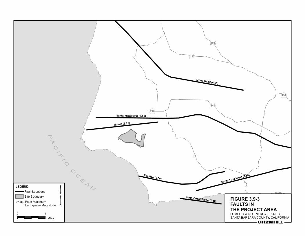
Regional Faults Faults near the Project area include the Honda, Santa Ynez River, and Pacifico faults, shown relative to the Project area in Figure 3.9-2. These and other faults that could impact the site also are presented in Table 3.9-2.
TABLE 3.9-2 Regional Faults within 15 miles of the Project Site
Fault Name
Approximate Distance from Center of Project Area
Data Source*
Maximum Earthquake
Magnitude (MCE) (mi) (km)
Honda 2.0 3.2 CSHM 6.25
Santa Ynez River 3.4 5.5 CSHM 7.50
Pacifico 4.8 7.8 CSHM 6.50
Lions Head 11.0 17.7 Blake 6.60
North Channel Slope 12.1 19.4 Blake 7.40
Santa Ynez (west) 12.1 19.4 CSHM 7.50
*CSHM = Caltrans Seismic Hazard Map, Blake (2002) from California Geological Survey Fault Database
The Honda fault is located approximately 2 miles north to northwest; the Santa Ynez River fault is about 3.4 miles north; and Pacifico fault is located roughly 4.8 miles south to southeast from the approximate center of the Project area referenced from the CSHM. The Honda fault trends east-west from near the coast at Point Perdernales, 7 miles along the north slope of the Santa Ynez mountains. According to the SSSE, this fault is considered inactive (Santa Barbara County, 1979b). However, the CSHM recognizes this fault in their database as potentially active. The CSHM considers this fault capable of generating an MCE magnitude of 6.25.
A branch of the Santa Ynez fault, the Santa Ynez River fault trends east-west for approximately 37 miles emanating from the Santa Ynez mountains and terminating near the coast just north of the Honda fault. The fault generally trends along the Santa Ynez River. The CSHM considers this fault capable of generating a MCE magnitude of 7.50.
The Pacifico fault trends east-west 13 miles at the western end of the Santa Ynez Mountains and meets the ocean near the mouth of Jalama Creek (Santa Barbara County, 1979b). This fault is considered to be a member of the Santa Ynez fault zone because of its similar trend and location directly west of the intersection of the north and south branches of the

FINAL 3.9 GEOLOGY AND SOILS
AUGUST 2008 3.9-9
Santa Ynez fault. The Pacifico fault is considered active. According to the CSHM, the Pacifico fault is capable of generating a MCE magnitude 6.50.
Several unnamed faults occur in the Tranquillon Mountain Area (in the vicinity of the Project area as shown on Figure 3.9-1). A left lateral strike-slip fault which trends northeast is present in the vicinity of Honda School. Three minor vertical faults occur south of the LWEF area. These faults are upthrown on their south sides. Two very old faults are present near Tranquillon Peak. These faults juxtapose older local geologic units, but are cut across by younger units or volcanics.
No faults, either active or potentially active, are shown to cross the Project area.
Fault Rupture An earthquake can cause significant surface displacement along its surface trace. For example, the 1971 San Fernando (Sylmar) Quake had a measured offset of up to 6.2 feet (2 meters), and the 1992 Landers Quake, located in the Mojave Desert, had offsets of up to 19 feet (6 meters). However, most earthquakes do not result in fault rupture, and fault rupture potential is highest across active faults. The Project area does not cross active or potentially active faults, according to the CGS and CSHM. In addition, the State of California has mapped known faults that could produce ground surface rupture in inhabited areas as part of the Alquist-Priolo Earthquake Fault Zoning Act. According to this fault zoning, the Project area does not fall within a mapped Alquist-Priolo fault zone. Therefore, fault rupture potential within the Project area is considered very low.
Ground Shaking Ground shaking from a seismic event could potentially result in the most damage and impacts to the Project area. Strong shaking from an earthquake can result in landslides and turbidity flows, ground lurching, structural damage, and liquefaction. Strong ground shaking can also set into motion other hazards such as fire, disruption of essential facilities and systems (water, sewer, gas, electricity, transportation, communications, irrigation, and drainage), releases of hazardous materials, or flood inundation as a result of dam or water tank failure. Ground shaking is controlled by the earthquake magnitude and source distance. A smaller magnitude earthquake occurring further away will produce lower ground motions compared to a stronger and closer event. Ground conditions also influence ground motion impacts. For example, a structure founded on dense or hard soils including bedrock will attenuate ground motions whereas loose or soft soil will amplify them.
The earthquake ground shaking hazard for a particular site is traditionally quantified using two levels of seismic ground motion:
•• Design Basis Earthquake (DBE) – ground motions associated with a 500 year mean return period or 10 percent probability of exceedance in 50 years
•• Maximum Credible Earthquake (MCE) – ground motions associated with a 2,500 year mean return period or 2 percent probability of exceedance in 50 years
Because it is less frequent, the MCE represents a larger magnitude of ground shaking than the DBE. The California Building Code (California Building Standards Commission, 2001) is inherently based on a DBE level event, with special provisions to provide for collapse prevention under the MCE.
3.9 GEOLOGY AND SOILS FINAL
3.9-10 AUGUST 2008
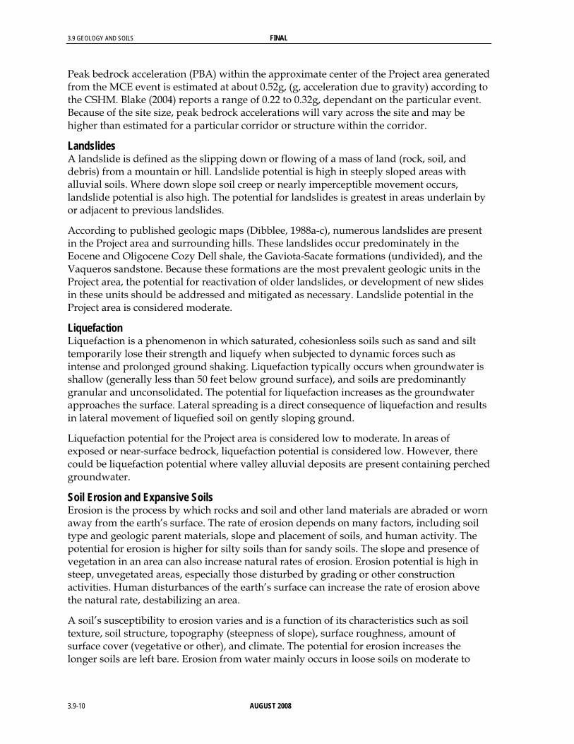
Peak bedrock acceleration (PBA) within the approximate center of the Project area generated from the MCE event is estimated at about 0.52g, (g, acceleration due to gravity) according to the CSHM. Blake (2004) reports a range of 0.22 to 0.32g, dependant on the particular event. Because of the site size, peak bedrock accelerations will vary across the site and may be higher than estimated for a particular corridor or structure within the corridor.
Landslides A landslide is defined as the slipping down or flowing of a mass of land (rock, soil, and debris) from a mountain or hill. Landslide potential is high in steeply sloped areas with alluvial soils. Where down slope soil creep or nearly imperceptible movement occurs, landslide potential is also high. The potential for landslides is greatest in areas underlain by or adjacent to previous landslides.
According to published geologic maps (Dibblee, 1988a-c), numerous landslides are present in the Project area and surrounding hills. These landslides occur predominately in the Eocene and Oligocene Cozy Dell shale, the Gaviota-Sacate formations (undivided), and the Vaqueros sandstone. Because these formations are the most prevalent geologic units in the Project area, the potential for reactivation of older landslides, or development of new slides in these units should be addressed and mitigated as necessary. Landslide potential in the Project area is considered moderate.
Liquefaction Liquefaction is a phenomenon in which saturated, cohesionless soils such as sand and silt temporarily lose their strength and liquefy when subjected to dynamic forces such as intense and prolonged ground shaking. Liquefaction typically occurs when groundwater is shallow (generally less than 50 feet below ground surface), and soils are predominantly granular and unconsolidated. The potential for liquefaction increases as the groundwater approaches the surface. Lateral spreading is a direct consequence of liquefaction and results in lateral movement of liquefied soil on gently sloping ground.
Liquefaction potential for the Project area is considered low to moderate. In areas of exposed or near-surface bedrock, liquefaction potential is considered low. However, there could be liquefaction potential where valley alluvial deposits are present containing perched groundwater.
Soil Erosion and Expansive Soils Erosion is the process by which rocks and soil and other land materials are abraded or worn away from the earth’s surface. The rate of erosion depends on many factors, including soil type and geologic parent materials, slope and placement of soils, and human activity. The potential for erosion is higher for silty soils than for sandy soils. The slope and presence of vegetation in an area can also increase natural rates of erosion. Erosion potential is high in steep, unvegetated areas, especially those disturbed by grading or other construction activities. Human disturbances of the earth’s surface can increase the rate of erosion above the natural rate, destabilizing an area.
A soil’s susceptibility to erosion varies and is a function of its characteristics such as soil texture, soil structure, topography (steepness of slope), surface roughness, amount of surface cover (vegetative or other), and climate. The potential for erosion increases the longer soils are left bare. Erosion from water mainly occurs in loose soils on moderate to

FINAL 3.9 GEOLOGY AND SOILS
AUGUST 2008 3.9-11
steep slopes, particularly during high-intensity storm events. Soil types in the Project range from shales, clays, and loams to rock outcrops. Most soils in the Project area are well developed and eroded. The potential for erosion in the Project area is moderate to high.
Expansive soils are clay-rich soils having the ability to shrink and swell with drying and wetting, respectively. The shrink-swell forces generated by expansive soils can result in differential movement beneath foundations causing structural damage to buildings and facilities. Based on review of the Project area geology, thin beds of bentonite clays are locally developed at the base of the Monterey shale or in the Tranquillon formation at various places in the Project area. Bentonite clays have high shrink-swell potentials. These formations are mainly present along the eastern half of the Project area with isolated zones within the western half. The potential for expansive soil at the site is considered low to moderate.
Compressible and Collapsible Soils Compressible soils are fine-grained and cohesive with normally low strength. They will readily consolidate and cause settlement when surcharged with fill or structure loads particularly when saturated. Settlement occurs slowly and can continue for years, though at a diminishing rate.
Collapsible soils are low density, fine-grained, predominantly granular usually containing fine sand and silt. When these soils become saturated under relatively low loads, soil particle rearrangement occurs resulting in substantial and rapid settlement. These soil types, therefore, are quite sensitive to either a rise in the groundwater table or increased surface water infiltration.
The Project area consists of shallow bedrock with small valleys containing alluvial deposits such as silt, sand, and gravel. Compressible soils are not expected, and their potential is considered low. Collapsible soils may be present within the alluvial deposits and will require further study to determine their potential. The SSSE has classified the Project area as having a low to moderate problem rating for compressible and collapsible soils (Santa Barbara County, 1979b).
Subsidence Subsidence refers to deep-seated settlement caused by withdrawal of fluids from below the ground surface such as water, oil, or natural gas. Subsidence can cover broad areas and movement can be quite large sometimes measured in tens of feet. Because movement covers such a broad area, settlement is normally differential and typically has the most significant impacts on linear structures such as pipelines, channels, and roadways. According the SSSE, no evidence of subsidence has been reported in the County (Santa Barbara County, 1979b). Localized withdrawal of groundwater, oil, or natural gas within or near the Project area is not present. Therefore, the potential for subsidence is considered low.
Tsunamis and Seiches Tsunamis are sea waves caused by submarine or coastline earthquakes. They can also be caused by submarine landslides. Seiches are waves generated in an inland water body by earthquake motions. Because the Project area is more than 2 miles from the ocean and much of it is over 1,000 feet above mean sea level, the Project would not be affected by tsunamis.

3.9 GEOLOGY AND SOILS FINAL
3.9-12 AUGUST 2008
Because no inland water bodies are present near the area, the Project would not be affected by seiches.
3.9.2 Regulatory Framework 3.9.2.1 State Alquist-Priolo Earthquake Fault Zoning Act of 1972 In response to the 1971 San Fernando Earthquake, which damaged numerous homes, commercial buildings, and other structures, California passed the Alquist-Priolo Earthquake Fault Zoning Act. The goal of the Act is to avoid or reduce damage to structures like that caused by the San Fernando Earthquake, by preventing the construction of buildings on active faults.
In accordance with the law, CGS maps active faults and the surrounding earthquake fault zones for all affected areas. Any Project that involves the construction of buildings or structures for human occupancy, such as an operation and maintenance building, is subject to review under this law. Structures for human occupancy must be constructed at least 50 feet (15 meters) from any active fault. No portions of the Project area are included within the Alquist-Priolo Earthquake Fault Zone designated by the State of California.
California Seismic Hazards Mapping Act of 1990 The Seismic Hazards Mapping Act is designed to protect the public from the effects of strong ground shaking, liquefaction, landslides, other ground failures, or other hazards caused by earthquakes. The Act requires site-specific geotechnical investigations to identify the hazard and formulation of mitigation measures before the permitting of most developments designed for human occupancy.
Special Publication 117, Guidelines for Evaluating and Mitigating Seismic Hazards in California, (California Department of Conservation, Division of Mines and Geology, 1997) constitutes the guidelines for evaluating seismic hazards other than surface fault rupture, and for recommending mitigation measures as required by Public Resources Code Section 2695(a).
California Building Code The State of California provides a minimum standard for building design through the 2001 California Building Code (CBC [California Building Standards Commission, 2001]). The CBC is based entirely on the 1997 Uniform Building Code (UBC), but has been modified for California conditions. It is generally adopted on a jurisdiction-by jurisdiction basis, subject to further modification based on local conditions. Commercial and residential structures are planned-checked by local building officials and not by state agencies.
Chapter 16 of the CBC contains specific requirements for seismic safety. The Project area is located in Seismic Zone 4, the highest zone in terms of seismic risk in California. Chapter 18 of the CBC regulates foundations and retaining walls. Chapter 33 of the CBC contains specific requirements pertaining to site demolition, excavation, and construction to protect people and property from hazards associated with excavation cave-ins and falling debris or construction materials. Construction activities are subject to occupational safety standards for excavation, shoring, and trenching as specified in California Office of Safety and Health and Administration (Cal-OSHA) regulations.

FINAL 3.9 GEOLOGY AND SOILS
AUGUST 2008 3.9-13
3.9.2.2 Local County of Santa Barbara Conformance with County Grading and Building Codes are considered generally satisfactory to address geologic hazards. The Seismic Safety and Safety Element (SSSE) recommends an adequate site-specific investigation be performed where the possibility of soil or geologic problems exist (Santa Barbara County, 1979b).
The Santa Barbara County Grading, Erosion, and Sediment Control Ordinance (Ordinance No. 3937, County of Santa Barbara, 1991) pertains to new grading, excavations, fills, cuts, borrow pits, stockpiling, and compaction of fill where the transported amount of materials exceeds 50 cubic yards or the cut or fill exceeds 3 feet in vertical distance to the natural contour of the land.
The SSSE contains a number of policies applicable to geologic resources. The consistency of the Project with those policies is addressed in detail in Section 3.10, Land Use.
3.9.3 Project Impacts, Mitigation, and Residual Impacts 3.9.3.1 Impact Assessment Methodology Impacts were assessed by comparing Project components to the following thresholds of significance.
3.9.3.2 Thresholds of Significance Based on Appendix G of the California Environmental Quality Act (CEQA) Guidelines, impacts would be considered significant if the Project would expose people or structures to potential substantial adverse effects from major geologic hazards, such as rupture of a known earthquake fault, seismically induced ground shaking or ground failure, or landslides. Impacts also would be significant if the Project would result in substantial erosion or siltation or be located on a geologic unit that was unstable or could become unstable as a result of the Project and result in further geologic hazards. Additionally, impacts could be significant if the Project were located on expansive soils or had soils that were incapable of adequately supporting septic tanks.
Additionally, the County Environmental Thresholds and Guidelines Manual (County, 2006) provides preliminary criteria for determining whether a particular activity could have a potentially significant impact on the environment. Geologic conditions are highly variable within the County; thus, the guidelines are not fixed thresholds upon which a determination of significant impact can be made, but they are useful for identifying where further study of site-specific conditions is required in order to assess impacts. The preliminary criteria are as follows:
1. The Project site or any part of the Project is located on land having substantial geologic constraints, as determined by the County. Areas constrained by geology include parcels located near active or potentially active faults and property underlain by rock types associated with compressible/collapsible soils or susceptible to landslides or severe erosion. “Special Problems” areas, designated by the County Board of Supervisors, have been established based on geologic constraints, flood hazards, and other physical limitations to development.

3.9 GEOLOGY AND SOILS FINAL
3.9-14 AUGUST 2008
2. The Project results in potentially hazardous geologic conditions, such as the construction of cut slopes exceeding a grade of 1.5 horizontal to 1 vertical.
3. The Project proposes construction of a cut slope over 15 feet in height as measured from the lowest finished grade.
4. The Project is located on slopes exceeding 20 percent grade.
3.9.3.3 Project Impacts Impact No. Impact Description Phase Impact Classification
GEO-1 Risk of damage to structures by fault rupture is very low.
Construction and Operations
Class III
Impact GEO-1: Fault Rupture. No potentially active or active faults are present in the Project area; thus, the risk of damage to structures is very low, and the impact would be adverse, but less than significant (Class III).
Impact No. Impact Description Phase Impact Classification
GEO-2 A major earthquake could result in ground shaking and liquefaction.
Construction and Operations
Class III
Impact GEO-2: Ground Shaking and Liquefaction. Because of the seismicity in the Project region, a major earthquake could occur before the Project is decommissioned, resulting in ground shaking and liquefaction. A geotechnical study would be conducted prior to construction to evaluate soil conditions and geologic hazards. As part of this study, Project area seismic analyses specific to the proposed construction corridors for the WTGs and the power line would be conducted, quantifying the impacts and presenting required seismic design parameters. Liquefaction potential also would be quantified during this study. Appropriate recommendations would be developed and could include such measures as constructing deep foundations, deep soil densification, and geopiers. Because the appropriate studies would be conducted and the Project would be required to be designed to appropriate engineering standards (Uniform Building Code Seismic Zone 4 standards), impacts from ground shaking and liquefaction would be adverse, but less than significant (Class III).
Impact No. Impact Description Phase Impact Classification
GEO-3 Construction activities could increase the potential for landslides and cause or reactivate existing landslides.
Construction Class II
Impact GEO-3: Landslides. By disturbing the land (for example, through activities such as vegetation removal and grading), construction activities could destabilize the soil and increase the potential for landslides. In addition, road construction could slow or redirect existing drainage, saturate adjacent lands, and cause or reactivate existing landslides in the Project area. However, a geotechnical study would be conducted to evaluate soil conditions and geologic hazards. As part of this study, existing landslides affecting proposed corridors and structures in the Project area would be evaluated, thus allowing the Applicant to avoid

FINAL 3.9 GEOLOGY AND SOILS
AUGUST 2008 3.9-15
locating roads and structures near existing landslide or potentially unstable areas where feasible. If avoidance is not feasible, impacts would be significant but mitigable (Class II).
Impact No. Impact Description Phase Impact Classification
GEO-4 Construction could accelerate or increase the potential for erosion from water and wind.
Construction Class III
Impact GEO-4: Soil Erosion. Construction of the Project would result in permanent disturbance to approximately 40 acres (Table 2-5). minor clearing of land. The clearing and grading, cut-and-fill activities, and potential soil compaction during construction could increase the potential for erosion. Road construction could also increase water runoff rates, resulting in accelerated soil erosion. The movement of equipment and materials during construction could destabilize the soil surface and increase erosion potential from water and wind. The most likely time for erosion to occur is after initial disturbance and before re-establishment of vegetative cover or placement of structures. Erosion can cause a number of problems, including loss of topsoil critical to agricultural use; slowed restoration rates; degraded water quality due to increased sediment loads; and damage to foundations, roadways, and other structures. A Storm Water Pollution Prevention Plan (SWPPP) would be developed in compliance with the State Water Resources Control Board Construction Storm Water Permit and would include Best Management Practices (BMPs). The proper implementation of erosion and sedimentation control procedures included in the Project SWPPP would reduce erosion rates during and after construction to essentially natural rates. Additionally, a Grading and Drainage Plan would be required, which also would minimize the potential for erosion through the implementation of BMPs. Impacts associated with erosion would be adverse, but less than significant (Class III).
Impact No. Impact Description Phase Impact Classification
GEO-5 Structures would be designed to appropriate engineering standards and would not be susceptible to significant damage produced by expansive soils.
Construction and Operations
Class III
Impact GEO-5: Expansive Soils. Based on the geotechnical study, buildings and structures would be designed to required and appropriate engineering standards and would not be susceptible to significant damage from shrinking and swelling forces produced by expansive soils. Impacts associated with expansive soils would be adverse, but less than significant (Class III).
Impact No. Impact Description Phase Impact Classification
GEO-6 Testing has determined that leach lines would be a suitable method of sewage effluent disposal.
Construction and Operations
Class III
Impact GEO-6: Sewage Effluent Disposal. Percolation testing was conducted at the Signorelli property, the site of the O&M facility, to determine the suitability of the surface soils to accept sewage effluent disposal by the method of leach lines. The tests were performed in

3.9 GEOLOGY AND SOILS FINAL
3.9-16 AUGUST 2008
12-inch diameter, pre-saturated borings using a 6-inch water head at depths of 4.0 to 4.5 feet below present ground surface. In addition, a 6-inch diameter boring was drilled to ensure that no free groundwater or impervious bedrock was located within 10 vertical feet of the proposed leach lines. It was determined that leach lines would be a suitable method of sewage effluent disposal. The report specified that leach line trenches should be 3.0 feet wide by 4.5 feet deep and that an application rate of 0.6 gallons per day per square foot of leaching area would be applicable. Per the Uniform Plumbing Code, sufficient area must be set aside for future expansion of the system by 100 percent; a dual system would be required (Coast-Valley Testing, Inc., 2006). Given the implementation of these standard requirements, impacts associated with the suitability of soils for the use of septic systems would be adverse, but less than significant (Class III).
Impact No. Impact Description Phase Impact Classification
GEO-7 Compressible soil and subsidence potential is considered low. Collapsible soil may be present within alluvial valleys and could cause settlement damage to structures and roadways.
Construction and Operations
Class III
Impact GEO-7: Compressible and Collapsible Soil, Subsidence. Compressible soil and subsidence potential within the Project area is considered low. Collapsible soil may be present within alluvial valleys of the Project area and could cause settlement damage to structures and roadways. However, this issue would be addressed through the geotechnical study, which would identify appropriate measures should collapsible soils be present. Such measures could include soil removal and recompaction, prewetting, and, potentially, deep foundation or deep soil densification techniques. Impacts associated with compressible and collapsible soil and subsidence would be adverse, but less significant (Class III).
3.9.3.4 Applicant-proposed Mitigation Measures The following mitigation measures incorporate appropriate provisions of the Applicant-proposed mitigation measures listed in Section 2.8.4, with revisions as needed to ensure maximum feasible mitigation in accordance with Santa Barbara County policy.
The following Applicant-proposed mitigation measures are considered part of the Project description. They have been refined where appropriate to reflect the County Standard Conditions of Approval and Mitigation Measures (Santa Barbara County, 2002), including the addition of plan requirements, timing, and monitoring actions.
Mitigation Measure A-GEO-1: Seismicity. Project facilities shall be designed to Uniform Building Code Seismic Zone 4 standards.
Plan Requirements: The Applicant shall submit plans for buildings and structures indicating standards to the satisfaction of the County.
Timing: Prior to zoning clearance for the first phase of construction and prior to zoning clearance for subsequent Project phases.

FINAL 3.9 GEOLOGY AND SOILS
AUGUST 2008 3.9-17
MONITORING: County building inspectors will inspect the site prior to occupancy clearance (for the O&M facility) and prior to operation of the WTGs and power line (Addresses Impacts GEO-2, GEO-5, and GEO-7).
Mitigation Measure A-GEO-2: Grading and Drainage Plan. The Applicant shall prepare a final Grading and Drainage Plan, designed to minimize erosion and landslides, which includes the following measures:
a. Use diversion structures and spot grading to reduce siltation into adjacent streams during grading and construction activities
b. Design grading on slopes steeper than 3:1 to minimize surface water runoff
c. Limit grading during construction to the dry season (April 15 to November 1) to the extent practicable. If grading needs to be done outside of the dry season, Applicant will coordinate grading work with the County and will follow all applicable guidelines
d. Keep soil damp during grading activities to reduce the effects of dust generation
e. Stockpile excess topsoil on site and segregate it from other soils to facilitate future land restoration
f. Install erosion control structures where appropriate, including temporary erosion control structures, such as trench plugs and water bars, on moderately steep slopes
g. If slope stabilization impacts cannot be avoided, submit detailed plans of the excavation (with limits of cut and fill and slope restoration method) prior to construction for review and approval.
h. Restore soil elevation/topography consistent with the approved grading and erosion control plans.
i. Reseed all exposed graded surfaces with deep-rooted, native, drought-tolerant ground cover to minimize erosion. Geotextile binding fabrics shall be used if necessary to hold slope soils until vegetation is established.
j. Construct cut slopes no steeper than 1.5:1 unless topographic constraints prevent this possibility; then, incorporate special design features to prevent slope failure.
k. Construct fill slopes no steeper than 2:1 unless topographic constraints prevent this possibility; then, incorporate special design features to prevent slope failure.
l. Strip areas to receive fill of vegetation, organic topsoil, debris, and other unsuitable material. Place engineered fill in layers not exceeding 12 inches in loose thickness, properly moistened and compacted, and tested for 90 percent compaction.
m. Where fill is placed upon a natural or excavated slope steeper than about 5:1 (20 percent), construct a base key at the toe of the fill and bench the fill into the existing slopes. Embed the base key at least 2 feet into competent inorganic soils; then bench the fill horizontally into the existing slope at least 2 feet normal to the slope as the fill is brought up in layers.

3.9 GEOLOGY AND SOILS FINAL
3.9-18 AUGUST 2008
n. Designate a place for temporary storage of construction equipment at least 100 feet from any water bodies.
o. Project grading and earthwork shall be observed and tested by a geotechnical engineer or his representative to verify compliance with these mitigation measures.
Plan Requirements: The Grading and Drainage Plan shall be submitted for review and approval by the County, including County Flood Control, prior to zoning clearance for the first phase of construction and prior to the zoning clearance for subsequent Project phases. The plan shall be designed to address erosion and sediment control during all Project phases. Plan requirements shall be noted on all grading and building plans. The Applicant shall notify the County prior to commencement of grading.
Timing: Erosion and sediment control measures shall be in place throughout grading and development of the site until all disturbed areas are permanently stabilized. Graded surfaces shall be reseeded within 60 days of grading completion, with the exception of surfaces graded for the placement of structures. These surfaces shall be reseeded if construction of structures does not commence within 60 days of grading completion.
MONITORING: The County will photo document revegetation and ensure compliance with the plan. County grading inspectors will monitor technical aspects of the grading activities (Addresses Impacts GEO-3 and GEO-4).
Mitigation Measure A-GEO-3: Expansive Soils. Soil analyses shall be completed for expansion potential. Once Project design has been developed and the criteria for the facility performance have been established, the soils engineer shall review the mitigation measures and modify them as appropriate. If further measures are considered necessary to mitigate problems posed by expansive soils, the following alternatives shall be considered:
a. Over-excavation of expansive soils and replacement with non-expansive fill.
b. Support of structures on drilled shaft foundations.
c. Lime treatment of expansive subgrades.
Plan Requirements: Soil analyses and performance criteria shall be completed and submitted to the County for review and approval.
Timing: Prior to the zoning clearance for the first phase of construction and prior to the zoning clearance for subsequent Project phases.
MONITORING: County building inspectors will inspect the site to ensure that construction complies with the appropriate performance standards. (Addresses Impact GEO-5)
Mitigation Measure A-GEO-4: Project Support Facilities. Project support facilities such as bridge foundations shall be sited on cut pads to provide relatively uniform foundation support and reduce differential settlement. Alternatively, structure foundations shall be designed to tolerate potential differential settlement.
Plan Requirements: Building plans shall be submitted to the County for review and approval.

FINAL 3.9 GEOLOGY AND SOILS
AUGUST 2008 3.9-19
Timing: Prior to zoning clearance for the first phase of construction and prior to zoning clearance for subsequent Project phases.
MONITORING: County building inspectors will inspect the site to ensure that construction complies with the appropriate standards. (Addresses Impact GEO-7)
3.9.3.5 Residual Impacts With the implementation of the above mitigation measures, residual impacts to geology and soils would be adverse, but less than significant.

FIGURE 3.9-1
GEOLOGY WITHIN
THE PROJECT AREALOMPOC WIND ENERGY PROJECTSANTA BARBARA COUNTY, CALIFORNIA
LEGEND
PROJECT AREA GEOLOGY
SURFICIAL SEDIMENTS
QaValley and floodplain deposits of clay silt, sand and gravel
Qls Landslide Debris
Qoa Older dissected surficial deposits
SISQUOC SHALE
TsqdWhite-weathering, cream-white, punky laminateddiatomite, some thin ash beds
MONTEREY SHALE
Tm
Uppershale Unit; white-weathering, thin bedded, hard, brittle chertysiliceous shale with black linty laminae;Mohnian Stage
Tmd Punky white laminated diatomiti
Tml
Lower shale unit; white-weathering, soft, punky, fissile to platy, semi-siliceous shale,containing thin, gray-white calcareous strata;Luisian and Relizian Stages
Tmls
Massive light gray carbonate (dolomite) unit; lowest part sandy and locally pebbly innortheastern area
TRANQUILLION VOLCANIC FORMATION
TtrGray-white to tan, rhyolitic to andesitic flow breccia
VAQUEROS SANDSTONE
Tvqcg
Greenish-brown pebble conglomerate composed mostly of Francisian detritusin sandstone matrix, commonly fossiliferous;gray cobble conglomerate at La SalleCanyon; in most areas, uppermost partcomposed of greenish-tan, semi-friable sandstone
GAVIOTA - SACATE FORMATIONS, UNDIVIDED
Tg-Sa
Tan, semi-friable, thick bedded sandstone locally containing concretions and fossils,and interbedded gray micaceous siltstoneand clay stone; Refugian and upperNarizian (?) Stages
COZY DELL SHALE
Tcd
Light gray micaceous shale with minor thin, light gray to tan arkosic sandstone strata;Narizian Stage
Proposed PG&E Power Line
500-ft Buffer of Proposed PG&E Power Line
Applicant Leased Project Boundary
0 3,000
Feet
Tsass
Source: Adapted from figure prepared by CH2MHill

PA
LdH
PA
ScG
LeF2
LgF2
ScG
LhG
LdG
MgF2
LeE2
ScF2
ScG
LeF2
GaG
GaG
DaE2
LdG
LdG
LgE2
LdG
AE
LgF2
DaF2TaE2
ScF2
CkE2
LgF2
PA
LdG
ScF2AE
AE
CkG
DaF2
LdG
TaE2
LgF2
LgF2
ScF2
LgF2
LdG
ScF2TaE2
ScG
LgF2
LeF2
ScF2
ScG
LhGGaE
DaF2
LdG
LdH
ScF2
NbG
PASaE2
ScF2
LdH
LeE2
CkE2
CkD2
LgE2
GaG
GaG
LdG
LhG
ScG
ScD2
PA
ScF2 DaF2
LgE2
LeF2
LdG
GaE
ScD2 CdG
BgADaE2
CkF
NaF2
ScE2
BgC
LgF2
LeF2
CkD2
LdG
LeF2
LeE2
DaE2
LdH
BgC
GbG
ScF2
LgF2
DaE2
LeF2
CkE2
CkD2
SaF2
BgC
LeF2
LeE2
LdH
DaC
LeE2
CkE2
LdG
CkF
DaE2
LgE2
LhG
CkD2
LaF2
LdH
LdH
ScE2
CkF
BgC
SaD2
ScG
GbG
LgF2
CkF
LdG
CdG
GaG
ScF2
GaG
ScF2CkF
ScF2
GaG
CkD2
ScG
ScE2
GbG
GaG
CkD2
SaF2
ScF2
LgE2
ScE2
LeE2
SaD2
ScF2
ScE2
LeE2
CkF
ScF2
TaE2
GaG
CkE2
LdG
ScF2
ScG
LdH
LdG
ScF2
ScF2
GbG
ScF2
GaG
ScF2
CdG
GbGLgE2
ScE2
DaE2
LgE2
LgE2
LdG
CkG
ScG
LgF2
LdHSaD2
SaE2
ScF2
LgE2
ScE2
LgE2
LdG
ScF2
BhC
LdG
MeD2
NaF2
ScG
GaE
SaE2
ScG
ScG
DaE2
ScD2
DaF2
LhG
SaE2
GbG
GbG
LdG
W
ScF2
DaE2
LgE2
DaE2
LdG
LdG
Mx
Mv
LmG
LmG
BtA
SmG
SpG
SmF
SpG
BtC
BtA
SpG
MpG
Cv
SdA
SmF
PAsbc
LcG
LmG
LsF
Mv
SpG
Rs
SvC
LmG
CwG
CwG
GsF
SmF
TnC
BtC
GsE
LmG
GsG
SmG
MnA
SpGLmG
GuE
SmG
SpG
SpG
GmG
SmF
SmG
Sh
TnC
TrE3
Mv
GsF
LmG
SpG
SpG
MpG
BtA
W
LcF
Cv
CwG
DaF
LdG
TrE3
SpG
SmF
GsD
TsF
GsF
BtA2
W
TsF
Rs
MoATdF
SvC
SpG
SpG
TrE3
BtA2
StA
BtD2
EdA
GmE
Mw
W
SpG
BtD2
SpG
TrC
StC
GuE
StA
EdC2
StA
BtC
GsF
LsF
CwG3
SpG
TrD
StC
BtD2
SpG
GsF
SpG
TnC
BbD
TsF
CwG
SdA
GsE
CwF
Mu
SmG
Rs
GuE
LaF
GuE
TrE3
SmG
DaF
GsF
GsE
TnE2
BtD2
SpG
CuA
SpG
MnA
TdF
LmG
Mx
SpG
GsE
DaF
TdF
DaD
Mw
EdA
SdA
Mw
BtC
SpG
BtD2
BtC
Mw
BtC
CuA
TnE2
BwA
MnC
CuA
Mx
MnA
TnE2
SmG
GsESmE
TrC
LsG3
CuA
CwG
LsG3
DaE
Rs
LsEDaE
PAsbc
BtC
LmG
CwG
SpG
CuA
FIGURE 3.9-2
SOIL UNITS IN THE
PROJECT AREALOMPOC WIND ENERGY PROJECTSANTA BARBARA COUNTY, CALIFORNIA
LEGEND
Proposed PG&E Power Line
Approximate TurbineConstruction Corridors (Proposed)
Site Boundary
Soil Unit Boundaries
0 4,000
Feet
LA BEL DESCRIP T ION LA BEL DESCRIP T ION
AE Argixero lls And Xererts,Landslides Areas LgE2 Los Osos ClayLoam,15 To 30 Percent Slopes,Eroded
AgA Agueda SiltyClayLoam,0 To 2 Percent Slopes LgF2 Los Osos ClayLoam,30 To 50 Percent Slopes,Eroded
ArD Arnold Sand,5 To 15 Percent Slopes LhG Los Osos-M aymen Complex,50 To 75 Percent Slopes
ArF Arnold Sand,15 To 45 Percent Slopes LmG Lopez ShalyClayLoam,15 To 75 Percent Slopes
ArF3 Arnold Sand,9 To 45 Percent Slopes,SeverelyEroded LsE Los Osos-San Benito ClayLoams,15 To 30 Percent Slopes
BaC Ballard Fine SandyLoam,2 To 9 Percent Slopes LsF Los Osos-San Benito ClayLoams,30 To 45 Percent Slopes
BaD Ballard Fine SandyLoam,9 To 15 Percent Slopes LsG3 Los Osos-San Benito ClayLoams,30 To 75 Percent Slopes,SeverelyEroded
BbC Ballard GravellyFine SandyLoam,2 To 9 Percent Slopes M aA M arina Sand,0 To 2 Percent Slopes
BbD Ballard GravellyFine SandyLoam,9 To 15 Percent Slopes M aC M arina Sand,2 To 9 Percent Slopes
BgA Botella SiltyClayLoam,0 To 2 Percent Slopes M aE M arina Sand,9 To 30 Percent Slopes
BgC Botella SiltyClayLoam,2 To 9 Percent Slopes M aE3 M arina Sand,9 To 30 Percent Slopes,SeverelyEroded
BhC Botella ShalyClayLoam,2 To 9 Percent Slopes M eD2 M ilpitas-Positas Fine SandyLoam,9 To 15 Percent Slopes,Eroded
BtA Botella ClayLoam,0 To 2 Percent Slopes M gF2 M ontara StonyClay,15 To 50 Percent Slopes,Eroded
BtA2 Botella ClayLoam,0 To 2 Percent Slopes,Eroded M nA M etz LoamySand,0 To 2 Percent Slopes
BtC Botella ClayLoam,2 To 9 Percent Slopes M nA M etz LoamySand,0 To 2 Percent Slopes
BtD2 Botella ClayLoam,2 To 15 Percent Slopes,Eroded M nC M etz LoamySand,2 To 9 Percent Slopes
BwA Botella ClayLoam,Wet,0 To 2 Percent Slopes M oA M etz LoamySand,Overflow,0 To 2 Percent Slopes
Cc Camarillo VeryFine SandyLoam M pG M ine Pits And Dumps
CdG Capitan-Rock Outcrop Complex,50 To 75 Percent Slopes M r M ocho SandyLoam,Overflow
ChF Chamise ShalyLoam,15 To 45 Percent Slopes M u M ocho Fine SandyLoam
ChG2 Chamise ShalyLoam,30 To 75 Percent Slopes,Eroded M v M ocho Loam
CkD2 Crow Hill SiltyClayLoam,9 To 15 Percent Slopes,Eroded M w M ocho Loam,Overflow
CkE2 Crow Hill SiltyClayLoam,15 To 30 Percent Slopes,Eroded M x M ocho SiltyClayLoam
CkF Crow Hill SiltyClayLoam,30 To 50 Percent Slopes NaF2 Nacimiento SiltyClayLoam,30 To 50 Percent Slopes,Eroded
CkG Crow Hill SiltyClayLoam,50 To 75 Percent Slopes NbG Nacimiento-Landslide Complex,30 To 75 Percent Slopes
CtA Corralitos Sand,0 To 2 Percent Slopes NvC Narlon Sand,Hardpan Variant,2 To 9 Percent Slopes
CtD2 Corralitos Sand,2 To 15 Percent Slopes,Eroded PA Pits And Dumps
CuA Corralitos LoamySand,0 To 2 Percent Slopes PAsbc Pits And Dumps
CuC Corralitos LoamySand,2 To 9 Percent Slopes PtC Positas Fine SandyLoam,2 To 9 Percent Slopes
Cv CropleySiltyClay PtD Positas Fine SandyLoam,9 To 15 Percent Slopes
CwE Crow Hill Loam,15 To 30 Percent Slopes PtE Positas Fine SandyLoam,15 To 30 Percent Slopes
CwF Crow Hill Loam,30 To 45 Percent Slopes Rs Riverwash
CwG Crow Hill Loam,45 To 75 Percent Slopes SaD2 San Andreas-T ierra Complex,9 To 15 Percent Slopes,Eroded
CwG3 Crow Hill Loam,15 To 75 Percent Slopes,SeverelyEroded SaE2 San Andreas-T ierra Complex,15 To 30 Percent Slopes,Eroded
DaC Diablo Clay,2 To 9 Percent Slopes SaF2 San Andreas-T ierra Complex,30 To 50 Percent Slopes,Eroded
DaD Diablo SiltyClay,9 To 15 Percent Slopes ScD2 Santa Lucia ShalyClayLoam,9 To 15 Percent Slopes,Eroded
DaE Diablo SiltyClay,15 To 30 Percent Slopes ScE2 Santa Lucia ShalyClayLoam,15 To 30 Percent Slopes,Eroded
DaE2 Diablo Clay,15 To 30 Percent Slopes,Eroded ScF2 Santa Lucia ShalyClayLoam,30 To 50 Percent Slopes,Eroded
DaF Diablo SiltyClay,30 To 45 Percent Slopes ScG Santa Lucia ShalyLoam,50 To 75 Percent Slopes
DaF2 Diablo Clay,30 To 50 Percent Slopes,Eroded SdA Salinas SiltyClayLoam,0 To 2 Percent Slopes
EdA Elder SandyLoam,0 To 2 Percent Slopes SfD San Andreas-T ierra Complex,5 To 15 Percent Slopes
EdA2 Elder SandyLoam,0 To 2 Percent Slopes,Eroded SfE San Andreas-T ierra Complex,15 To 30 Percent Slopes
EdD2 Elder SandyLoam,9 To 15 Percent Slopes,Eroded SfG San Andreas-T ierra Complex,30 To 75 Percent Slopes
EmA Elder Loam,0 To 2 Percent Slopes Sh SandyAlluvial Land
EmC Elder Loam,2 To 9 Percent Slopes SmD Santa Lucia ShalyClayLoam,9 To 15 Percent Slopes
EnA2 Elder ShalyLoam,0 To 2 Percent Slopes,Eroded SmE Santa Lucia ShalyClayLoam,15 To 30 Percent Slopes
EnC2 Elder ShalyLoam,2 To 9 Percent Slopes,Eroded SmF Santa Lucia ShalyClayLoam,30 To 45 Percent Slopes
GaE Gaviota SandyLoam,9 To 30 Percent Slopes SmG Santa Lucia ShalyClayLoam,45 To 75 Percent Slopes
GaG Gaviota SandyLoam,30-75 Percent Slopes SnD Santa Ynez GravellyFine SandyLoam,9 To 15 Percent Slopes
GbG Gaviota-Rock Outcrop Complex,50 To 75 Percent Slopes SpG SedimentaryRock Land
GmE Gaviota SandyLoam,15 To 30 Percent Slopes SrE Shedd SiltyClayLoam,15 To 30 Percent Slopes
GmG Gaviota SandyLoam,30 To 75 Percent Slopes SsF Shedd SiltyClayLoam,Diatomaceous Variant,30 To 45 Percent Slopes
GsD Gazos ClayLoam,9 To 15 Percent Slopes StA Sorrento SandyLoam,0 To 2 Percent Slopes
GsE Gazos ClayLoam,15 To 30 Percent Slopes StC Sorrento SandyLoam,2 To 9 Percent Slopes
GsF Gazos ClayLoam,30 To 45 Percent Slopes SvC Sorrento Loam,2 To 9 Percent Slopes
GsG Gazos ClayLoam,45 To 75 Percent Slopes SwB2 Sorrento ClayLoam,0 To 5 Percent Slopes,Eroded
GuE Gullied Land TaE2 Tierra-San Andreas Complex,15 To 30 Percent Slopes,SeverelyEroded
LaF Landslides TcG Terrace Escarpments,Sandy
LaF2 Linne ClayLoam,30 To 50 Percent Slopes,Eroded TdF Terrace Escarpments,Loamy
LcE Linne ClayLoam,15 To 30 Percent Slopes TnC Tierra SandyLoam,2 To 9 Percent Slopes
LcF Linne ClayLoam,30 To 45 Percent Slopes TnD2 Tierra SandyLoam,9 To 15 Percent Slopes,Eroded
LcG Linne ClayLoam,45 To 75 Percent Slopes TnE2 Tierra SandyLoam,15 To 30 Percent Slopes,Eroded
LdG Lodo Loam,30 To 75 Percent Slopes TrC Tierra Loam,2 To 9 Percent Slopes
LdG Lopez-Rock Outcrop Complex,50 To 75 Percent Slopes TrD Tierra Loam,9 To 15 Percent Slopes
LdH Lopez-Rock Outcrop Complex,75 To 100 Percent Slopes TrE3 Tierra Loam,5 To 30 Percent Slopes,SeverelyEroded
LeE2 Lopez-Santa Lucia Complex,9 To 30 Percent Slopes,Eroded TsF Tierra ClayLoam,15 To 45 Percent Slopes
LeF2 Lopez-Santa Lucia Complex,30 To 50 Percent Slopes,Eroded W Water
Source: Adapted from figure prepared by CH2MHill
PACIFIC
O
C
EAN
£¤101
|ÿ1
|ÿ246
|ÿ135
|ÿ154
|ÿ246
Santa Ynez River (7.50)
Lions Head (6.60)
Pacifico (6.50)
Honda (6.25)
Santa Ynez West (7.50)
North Coast Slope (7.40)FIGURE 3.9-3
FAULTS IN
THE PROJECT AREALOMPOC WIND ENERGY PROJECTSANTA BARBARA COUNTY, CALIFORNIA
LEGEND
Fault Locations
Site Boundary
0 4
Miles
(7.50) Fault MaximumEarthquake Magnitude