Embed Size (px)
Citation preview

38” EPP Slick Build manual
Please read this manual carefully before beginning assembly.
This aircraft is constructed of EPP (Expanded Polypropylene) Foam. This makes the 38”Slick
light and extremely durable, able to withstand repeated crashes without major damage. This
makes the 38” Slick an ideal 3D trainer or practice aircraft. Additionally, designer Andrew Jesky
has developed the Slick to have excellent flight characteristics for all types of aerobatics.
However, the durability and performance of this aircraft will depend upon proper assembly by
you, the builder. For best results, read and follow this manual.

Building Techniques
The 38” Slick uses specific building techniques for EPP foam. Most glues and tapes will not
adhere well to EPP foam. We recommend a glue called “Welder” made by Homax Products Inc,
it is Homax part #730657. We carry this glue at www.3dhobbyshop.com and attempt to keep it
in stock at all times. If you need an alternate source, it is available from
www.homaxproducts.com, at most Lowe’s home improvement stores, and at the time of this
writing, a quick search of the internet revealed at least 20 additional online sources. Correct
assembly of the 38” Slick kit requires approximately 1.5 tubes of welder glue.
The Welder glue will be used to assemble the EPP foam pieces, and also to create the hinges on
this aircraft. Welder glue, when dry, is tough and flexible and makes an excellent hinge
material. If you are not familiar with the technique of making glue hinges on EPP foam aircraft,
a video may be most helpful to explain this technique. We have produced an instructional
video series covering the build of our 33” EPP Extra. The 33” Extra and the 38” Slick are built
using similar techniques. We highly recommend that you watch the 33” Extra instructional
videos before building your Slick if you are unfamiliar with these techniques.
The 33” Extra videos are hosted on www.youtube.com The exact address of the video on
hinging is: http://www.youtube.com/watch?v=RNpTN5S-wdc although it is easier to simply
navigate to the www.youtbe.com and type “3DHS EPP Build videos” into the search bar. There
are seven parts to the build video.
You will also be cutting pieces of carbon fiber rod and bar stock for this build. The best way to
cut carbon fiber is with a dremel or other rotary tool, with proper eye and skin protection.
However, you can cut carbon rod by rolling the rod under the blade of hobby knife on a hard
surface. Be careful when handling carbon fiber after you have cut it to avoid splinters, and
always wear proper eye protection.
Finally, you will be making Z-bends on steel music wire in this build. We show in the manual
and aforementioned videos how to make them with needle-nose pliers, but a set of “Z-bend
pliers” such as Hangar9 part #HAN119 makes this job much quicker and simpler.

Equipment
Motor: Hacker A20-26M or A20-20L
ESC: Hacker X12 or X20
Battery: 3S 900-1350mah
Servos: 4 x Hitec HS-65
Micro receiver
Velcro for battery retention
Assembly
Lay out the wing with ailerons, top (red) side up. As shown, apply weights to the foam pieces to hold
them in place during the hinging process.

Line up the ailerons with the wing perfectly, then apply a 1/8” wide bead of Welder glue all along the
hinge line.

Using a razor blade or stiff scraper (old credit card, hotel key card) scrape the hinge line as shown. This
will remove some of the glue and the glue that is left behind will be in a thin stripe about ½-3/4 inch
wide along the hinge. It does not take much thickness to create a strong hinge, the glue should be very
thin. Remember: more glue can always be added to a thin hinge, but thick glue is heavy and stiff and
cannot be easily take away. See video tutorial mentioned at the beginning of this manual for more
information.
Repeat for other aileron. Allow to dry.
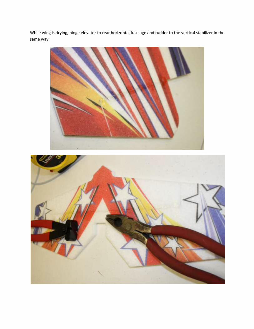
While wing is drying, hinge elevator to rear horizontal fuselage and rudder to the vertical stabilizer in the
same way.

For extra durability, your kit includes a piece of white floss which can be used to strengthen
your hinges. Cut the floss into short pieces approximately ¾ inch long. Use a small amount of
welder glue to glue these across the hinges on your Slick. Use your razor or scraper to remove
any excess glue while flattening the floss down against the foam. We recommend applying the
floss to the wing tip end and the inboard end of each aileron and to the ends of the elevator
hinge line.
When you do this, the floss will almost disappear against the foam. This technique will add
lifespan to your hinges.
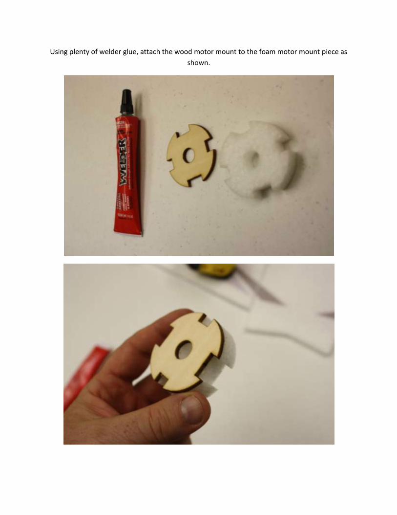
Using plenty of welder glue, attach the wood motor mount to the foam motor mount piece as
shown.

When your hinges are completely dry, set the rudder aside. Assemble the nose, wing,
horizontal fuselage, and horizontal tail as shown with welder glue. Punch out foam squares
from pieces as shown.

The wing and elevator each have a slot machined into their bottom side to accept carbon bar
spars. These slots will have residual foam in them which will need to be cleaned out. Use your
hobby knife or the end of a piece of carbon to get the foam out of the slots.
When the slots are empty, you can install the spars, starting with the pre-cut 36.5” wing spar. It
is important to use plenty of welder glue for this. Coat the carbon spar in glue, and put plenty
of glue in the slot. Then press the spar into the slot. Glue will squeeze out. Squeegee this glue
down flat with your razor or scraper

Place weights on the wing as necessary to make sure the wing and spar dries flat and straight.
Repeat the procedure to install the pre-cut 14.5” long flat elevator spar into the elevator. Allow to dry.

Next we will be installing the bottom half of the vertical fuselage. Note that this has tabs that extend
into slots in the horizontal section.
Glue the bottom vertical fuselage in as shown, using plenty of glue. Use the plywood parts sheet in your
kit or another 90 degree tool to make sure it is straight and level . Allow to dry.

You will need to check the fit of the elevator to the vertical fuselage. Because the EPP foam is flexible,
the elevator opening may need to be trimmed as shown to allow full elevator movement.

The Slick uses a carbon rod truss to stiffen the fuselage. This truss runs along both sides of the aircraft.
Your kit contains 48” lengths of carbon rod for this truss. In this section of the build, you will be directed
to cut sections of specific length from this rod and glue these sections into the fuselage as shown. Use
Welder glue for these steps. It is tempting to use CA glue for speed, but Welder will give a much
stronger and more durable structure.
Start by cutting 2 pieces, each 6 inches long.
To install the bracing pieces, put welder glue on the ends and press them into the foam with a twisting
motion.

Install the first two 6” pieces as shown.
After you have these installed, go back and place a drop of Welder glue on the spot where each rod is
inserted into the foam and spread it out to make a spot about ¼” wide. This will produce a very strong
installation when dry. Do this for every place where a carbon rod is inserted into the EPP foam.
Cut 2 more 6” long pieces. Install as shown.

The next four pieces are 8” long. Install as shown.

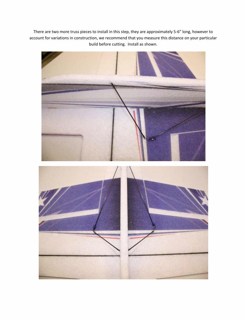
There are two more truss pieces to install in this step, they are approximately 5-6” long, however to
account for variations in construction, we recommend that you measure this distance on your particular
build before cutting. Install as shown.

Locate the 2mm plywood parts sheet. To release parts from the sheet, cut the tab areas with a sharp
hobby knife. NOTE: You will not use all of the pieces on the sheet.
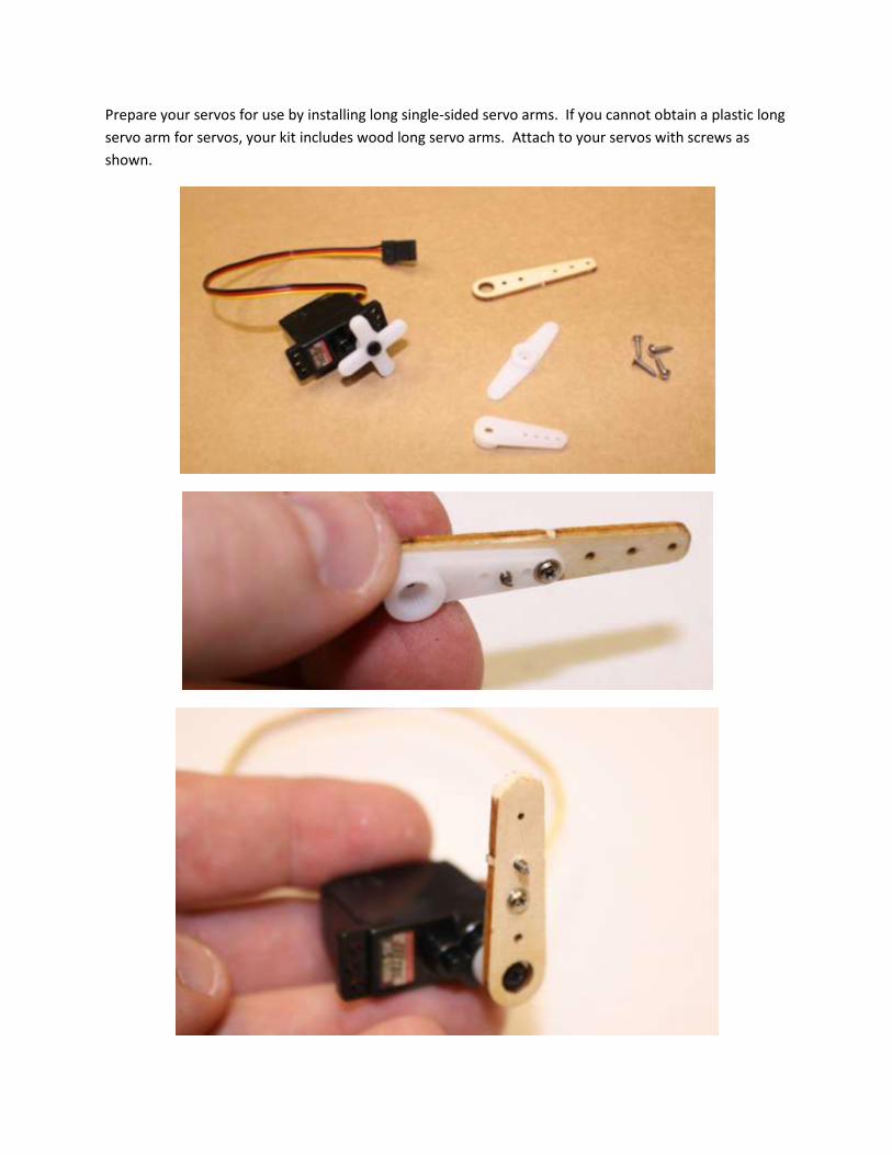
Prepare your servos for use by installing long single-sided servo arms. If you cannot obtain a plastic long
servo arm for servos, your kit includes wood long servo arms. Attach to your servos with screws as
shown.

Install aileron control horns into the ailerons as shown. The slots are pre-cut into the ailerons, use
planet of welder glue. Note that the horns go on the BOTTOM of the wings, the side you are currently
working on.
Cut two pieces of the included steel music wire into sections 3.0” long. Using Z-bend pliers or needle-
nose pliers, add Z-bends as shown, which reduces the overall length to about 2.75”.

If you want to keep your servos clean of glue residue, you can wrap the servo cases in masking tape.
Install the aileron servos with a large dab of welder adhesive as shown.
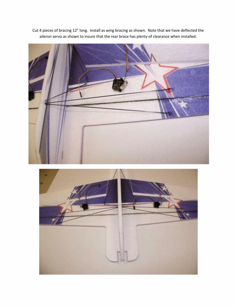
Cut 4 pieces of bracing 12” long. Install as wing bracing as shown. Note that we have deflected the
aileron servo as shown to insure that the rear brace has plenty of clearance when installed.

Theese are the parts for the landing gear legs, 2 pre cut legs 8” long and 2 pre cut axles 1.5” long, and
one piece of carbon fiber yarn. Cut the carbon fiber yarn into two equal length pieces.
Fold a piece of paper as shown to make a 45 degree angle tool and lay out one set of leg pieces along it
as shown.

Using a drop of thick CA glue, glue the leg pieces together at the 45 degree angle. Do the same to the
second set.
Using thick CA, glue one end of the carbon fiber yarn into the joint as shown.

Wrap the yarn tightly around the joint as shown and soak the yarn with thin CA. Allow to dry, then trim
off the end of the yarn. Repeat for second leg.

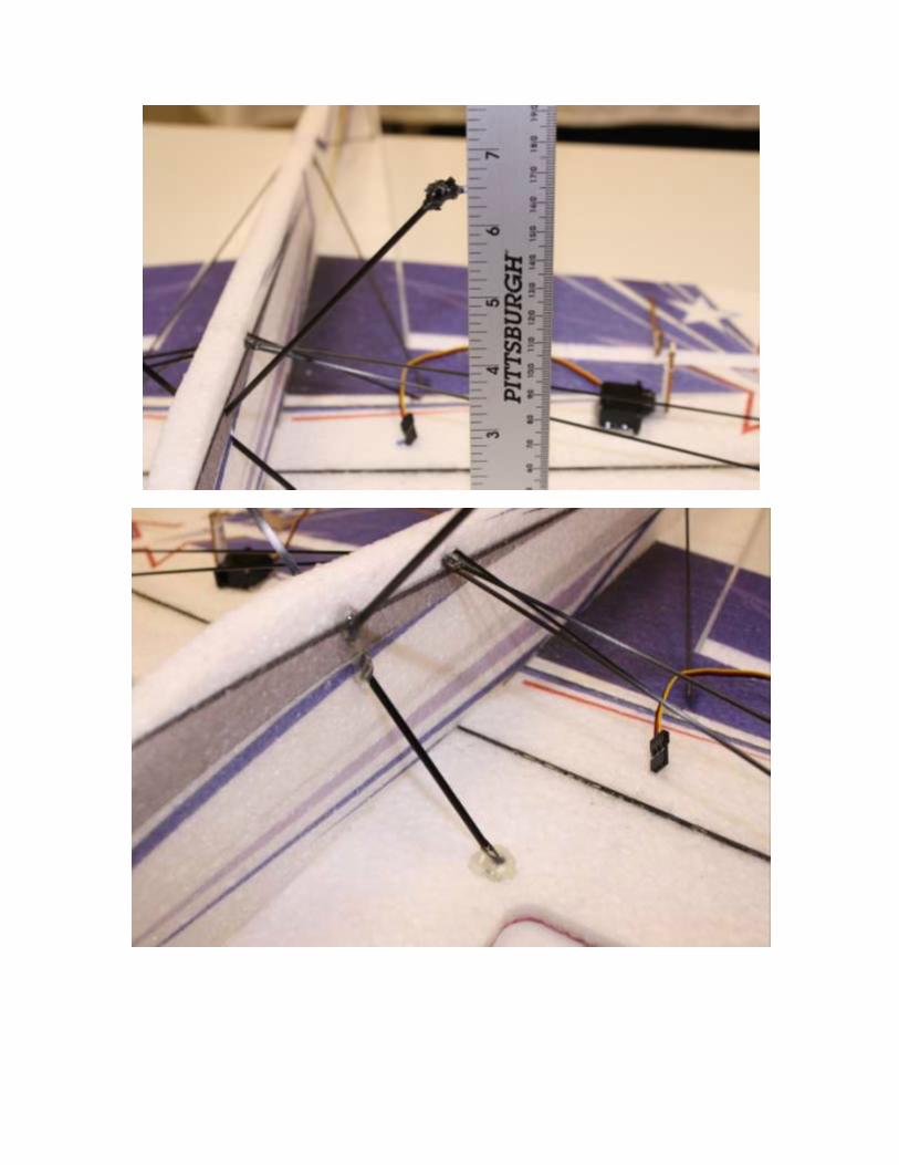
Make a cut into the vertical fuselage above the wing leading edge and insert the landing gear legs as
shown. Make sure the gear legs are the same height above the wing (so that the plane will sit level
when you turn it over) and tack them into place with a few drops of thick CA, then spread a generous
amount of Welder glue over the spots where the gear legs meet the wing and the fuselage as shown.
Allow to dry.

Install the wheels and a short section of included silicone tubing as a wheel retainer. Add a tiny drop of
CA glue to the wheel retainer.

Take the 3” section of pre-cut round rod and install it with welders glue as shown for use as a tail skid.
Apply a thin layer of welder glue to the nose area as shown.
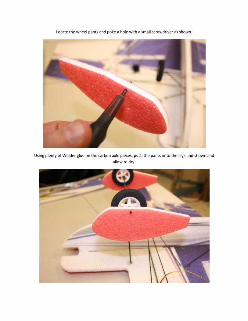
Locate the wheel pants and poke a hole with a small screwdriver as shown.
Using plenty of Welder glue on the carbon axle pieces, push the pants onto the legs and shown and
allow to dry.

Turn the airplane right-side up to continue work. Trial-fit the upper fuselage onto the lower fuselage
and wing.
After you are satisfied with the fit, glue the upper fuselage on with Welder glue. Install the motor
mount piece as well with plenty of welder glue to help align the nose, and use a drop of CA to hold the
tail end perfectly together while the welder dries.

Using a sharp hobby knife, bevel the bottom of the rudder below the vertical stabilizer as shown.

Test fit the vertical stabilizer and rudder to the fuselage and check the swing of the rudder.
When you are satisfied with the fit, glue the vertical stabilizer to the fuselage using CA first so that if will
hold alignment, and adding a bead of Welder to each side of the joint for durability.

Allow to dry, then add a bead of welder glue to the bottom of the rudder which you beveled earlier. Not
much welder glue is needed here to form a hinge here, wipe away excess glue and allow to dry.

Using a hobby knife, make a pass-through slot for servo wires through the horizontal fuselage as shown.
Test fir your servos. Trim the openings as needed, as shown.
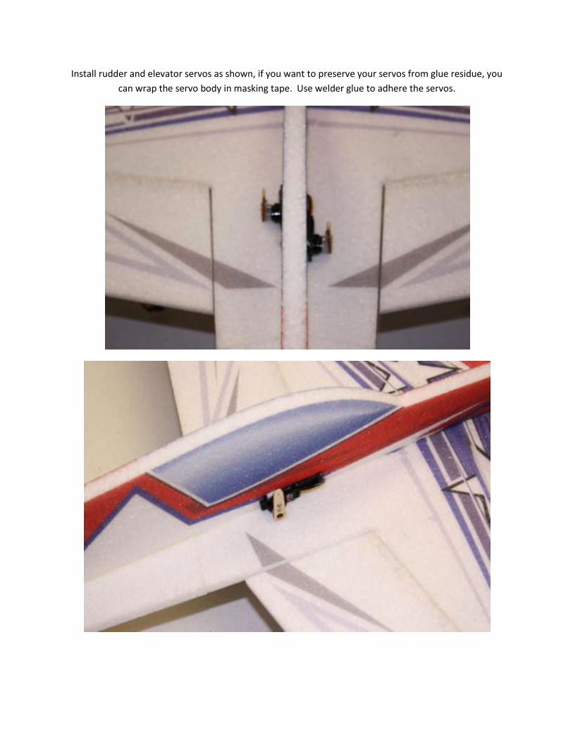
Install rudder and elevator servos as shown, if you want to preserve your servos from glue residue, you
can wrap the servo body in masking tape. Use welder glue to adhere the servos.

Install the elevator horn into pre-cut slot as shown, using Welder glue.
Install rudder horn into pre-cut slot as shown, using Welder glue. Trim approx3/8” from the back of the
rudder horn to fit the pre-cut slot.

Locate the pre-cut elevator (17”) and rudder (19.5”) carbon pushrods. Cut 4 pieces of included heat-
shrink tubing 1” long each. Also cut and bend 4 Z-bend wire sections 1.25-1.5” long each as shown.

Assemble one end of each pushrod as shown. Shrink the tubing onto the pushrod capturing the z-bend.
Slide the pushrod holders onto the pushrods as shown.
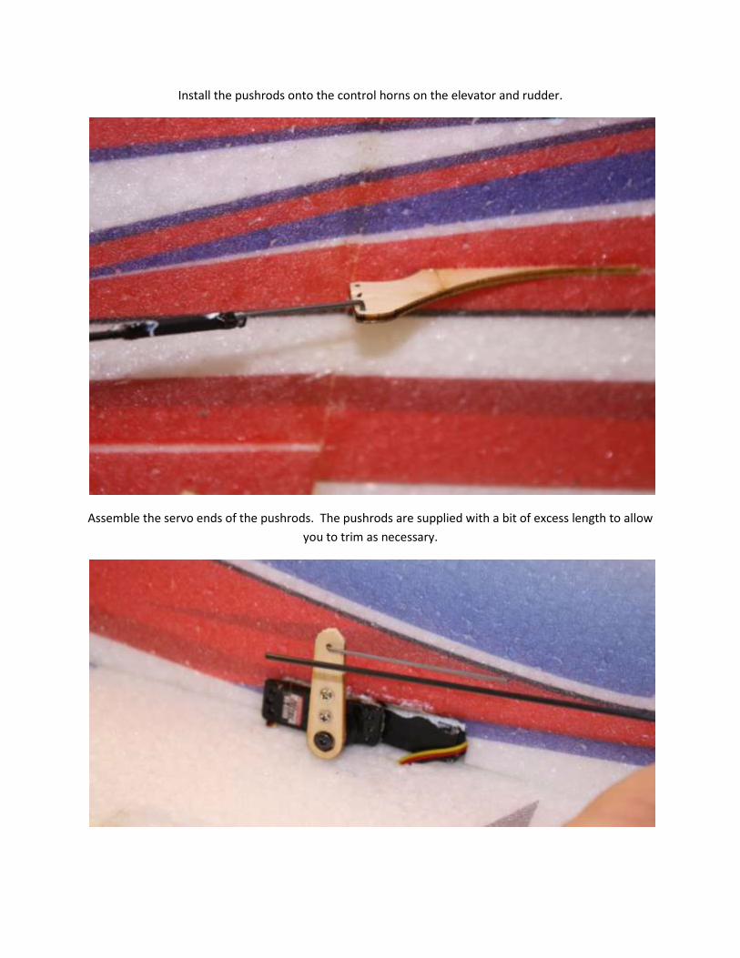
Install the pushrods onto the control horns on the elevator and rudder.
Assemble the servo ends of the pushrods. The pushrods are supplied with a bit of excess length to allow
you to trim as necessary.

When you shrink the tubing on the servo end of the pushrods, you are working close to the foam. Use a
piece of plywood to shield the foam while you shrink with a match or soldering iron.
At the mid-point of each pushrod, make a slot with your hobby knife and glue in the pushrod holder.
Trim off any excess length on the plywood pushrod holder.

Screw your brushless motor onto the motor mount.

Attach your ESC to the bottom of the fuselage with a dab of welder glue. Install your micro receiver as
shown. Install a 3-4” extension on one aileron servo if needed and plug in all servos.
Install Velcro for battery holding as shown. NOTE: Self-adhesive Velcro does not stick well to EPP. We
recommend using welder glue with a few drops of CA to hold the Velcro in place while the Velcro dries.

Remove the prop and plug in your battery. Center your servos and center your control surfaces. Make
any needed adjustment to pushrod length by sliding the wire Z-bends within the heat shrink tubing.
Once you have everything centered (Be thorough! Check your sub-trim on your radio!) add a drop of
thin CA glue to each Z-bend where it enters the heat shrink tubing. This will lock the Z-bend in place.
Setup values:
Recommended Center of Gravity: CG - 4”-5” behind the leading edge of the wing where wing meets
fuselage.
(This is approximately 2-3” behind the carbon main wing spar. After some flights, you should adjust the
CG (by moving the battery forward or aft) to get precisely the feel you want.
Control throws for 3D flight:
Elevator: 45 degrees up and down.
Ailerons: 45 degrees up and down.
Rudder: Maximum available without touching elevator.
We recommend the use of 75% expo on all controls to start.