Embed Size (px)
Citation preview
1/9
YANMAR SERVICE NEWS Title Maintenance of Con. Rod and Con. Rod Bolts
[Rev. 2: 6NY16,6RY,6EY18,6/8EY26 added] No.;S/N.QE5-003 Rev.2 Date ;July 2009
Use Marine Main & Aux.; Industrial Engine Model ALL
Engine Nos.
We summarized the maintenance procedures for the con. rod and con. rod bolts of the engine models presently produced and other major models being used in the field as follows. Please have a read through this Service News since the maintenance of con. rod and con. rod bolts represent an important maintenance item in using your engine safely for a long time. In addition, apply the angle tightening method, upon your subsequent servicing opportunities, according to the procedures as described in this Service News also to the connecting rods of the engines already shipped that have been tightened by the torque tightening method. (The standard maintenance values of con. rods for both the new and old engine models are added for your reference.)
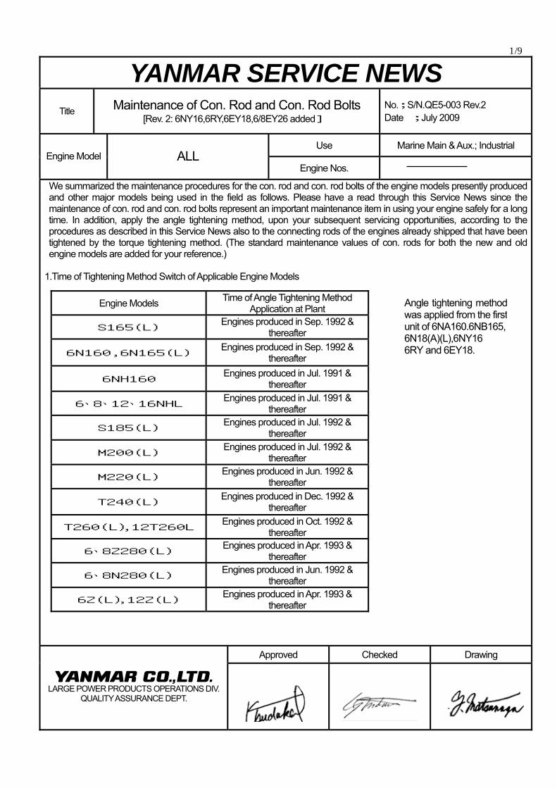
1.Time of Tightening Method Switch of Applicable Engine Models
Approved Checked Drawing
LARGE POWER PRODUCTS OPERATIONS DIV.
QUALITY ASSURANCE DEPT.
Engine Models Time of Angle Tightening Method Application at Plant
S165(L) Engines produced in Sep. 1992 & thereafter
6N160,6N165(L) Engines produced in Sep. 1992 & thereafter
6NH160 Engines produced in Jul. 1991 & thereafter
6、8、12、16NHL Engines produced in Jul. 1991 & thereafter
S185(L) Engines produced in Jul. 1992 & thereafter
M200(L) Engines produced in Jul. 1992 & thereafter
M220(L) Engines produced in Jun. 1992 & thereafter
T240(L) Engines produced in Dec. 1992 & thereafter
T260(L),12T260L Engines produced in Oct. 1992 & thereafter
6、8Z280(L) Engines produced in Apr. 1993 & thereafter
6、8N280(L) Engines produced in Jun. 1992 & thereafter
6Z(L),12Z(L) Engines produced in Apr. 1993 & thereafter
Angle tightening methodwas applied from the firstunit of 6NA160.6NB165,6N18(A)(L),6NY16 6RY and 6EY18.
2/9 2. Angle Mark 1) Concerning S165, N165, NHL and S185, the mark is
provided only at one position since the space for punching the angle mark on the con. rod is limited. Accordingly, we supplied the accessory angle gauge tool, (Fig.4).
Angle Gauge Part Number; For S165,6N165,NHL :133670-92510
For S185 :146613-92510
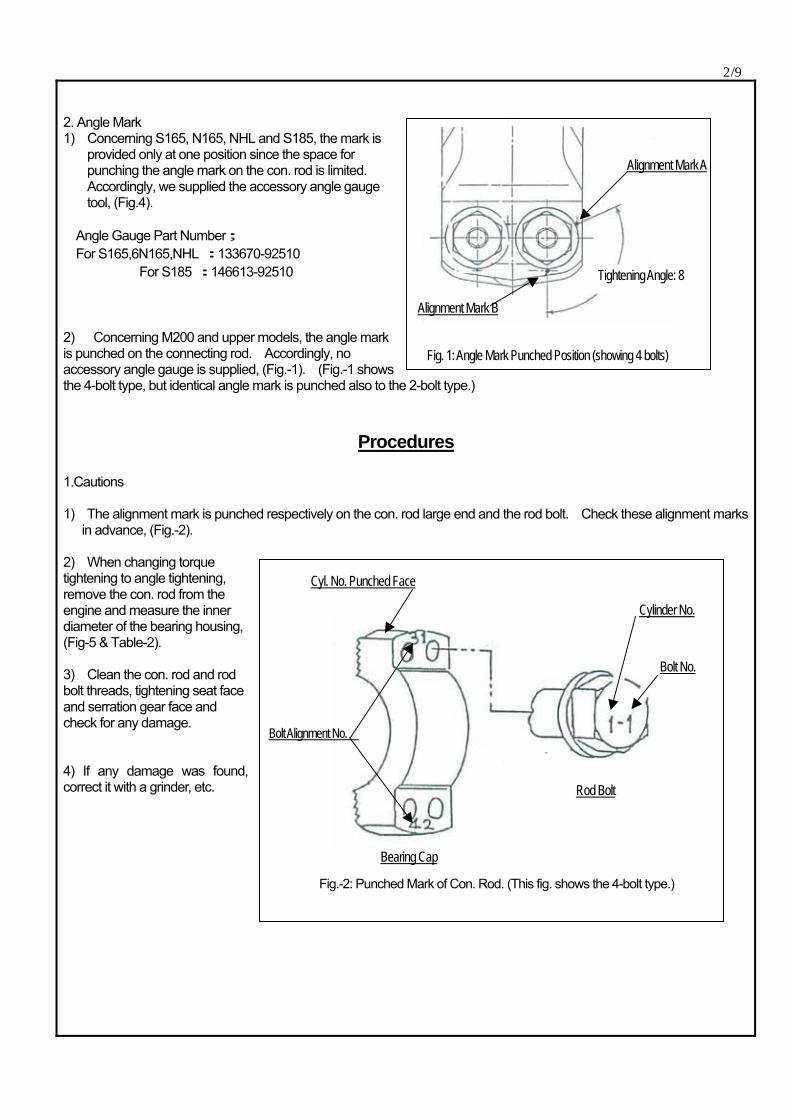
2) Concerning M200 and upper models, the angle mark is punched on the connecting rod. Accordingly, no accessory angle gauge is supplied, (Fig.-1). (Fig.-1 shows the 4-bolt type, but identical angle mark is punched also to the 2-bolt type.)
Procedures
1.Cautions 1) The alignment mark is punched respectively on the con. rod large end and the rod bolt. Check these alignment marks
in advance, (Fig.-2). 2) When changing torque tightening to angle tightening, remove the con. rod from the engine and measure the inner diameter of the bearing housing, (Fig-5 & Table-2). 3) Clean the con. rod and rod bolt threads, tightening seat face and serration gear face and check for any damage. 4) If any damage was found, correct it with a grinder, etc.
Fig. 1: Angle Mark Punched Position (showing 4 bolts)
Alignment Mark A
Alignment Mark B
Fig.-2: Punched Mark of Con. Rod. (This fig. shows the 4-bolt type.)
Cyl. No. Punched Face
Cylinder No.
Bolt No.
Rod Bolt
Bolt Alignment No.
Bearing Cap
Tightening Angle: 8
3/9 5) Check the cylinder number and bolt number punched on the rod bolt head and bearing cap and installed to the
specified position. 6) Apply PROTEC GREASE to the rod bolt thread and tightening seat face in order not to make burrs. If PROTEC
GREASE is not available, apply the seizing inhibitor (molybdenum disulfide). 7)Check that the rod bolt seat face can be screwed in up to the surface lightly by hand. 8) When the rod bolts were replaced, implement as follows:
① Fasten and loosen the rod bolt from/to its surface position to/from the specified surface angle position for about 3 times in order to break in the thread and tightening seat face fully. (Apply the seizing inhibitor to the thread and tightening seat face in advance.)
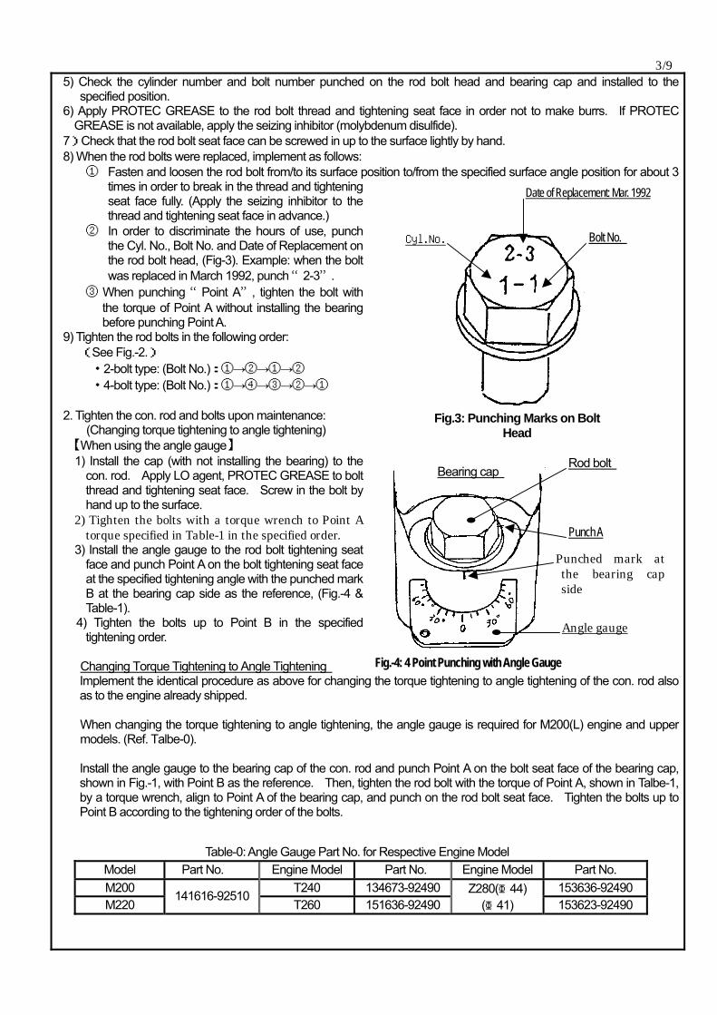
② In order to discriminate the hours of use, punch the Cyl. No., Bolt No. and Date of Replacement on the rod bolt head, (Fig-3). Example: when the bolt was replaced in March 1992, punch “2-3”.
③ When punching “Point A”, tighten the bolt with the torque of Point A without installing the bearing before punching Point A.
9) Tighten the rod bolts in the following order: (See Fig.-2.) ・2-bolt type: (Bolt No.):①→②→①→② ・4-bolt type: (Bolt No.):①→④→③→②→① 2. Tighten the con. rod and bolts upon maintenance: (Changing torque tightening to angle tightening) 【When using the angle gauge】 1) Install the cap (with not installing the bearing) to the
con. rod. Apply LO agent, PROTEC GREASE to bolt thread and tightening seat face. Screw in the bolt by hand up to the surface.
2) Tighten the bolts with a torque wrench to Point A torque specified in Table-1 in the specified order.
3) Install the angle gauge to the rod bolt tightening seat face and punch Point A on the bolt tightening seat face at the specified tightening angle with the punched mark B at the bearing cap side as the reference, (Fig.-4 & Table-1).
4) Tighten the bolts up to Point B in the specified tightening order.
Changing Torque Tightening to Angle Tightening Implement the identical procedure as above for changing the torque tightening to angle tightening of the con. rod also as to the engine already shipped. When changing the torque tightening to angle tightening, the angle gauge is required for M200(L) engine and upper models. (Ref. Talbe-0). Install the angle gauge to the bearing cap of the con. rod and punch Point A on the bolt seat face of the bearing cap, shown in Fig.-1, with Point B as the reference. Then, tighten the rod bolt with the torque of Point A, shown in Talbe-1, by a torque wrench, align to Point A of the bearing cap, and punch on the rod bolt seat face. Tighten the bolts up to Point B according to the tightening order of the bolts.
Fig.3: Punching Marks on Bolt
Head
Date of Replacement: Mar. 1992
Bolt No. Cyl.No.
Fig.-4: 4 Point Punching with Angle Gauge
Bearing cap Rod bolt
Punch A
Punched mark atthe bearing capside
Angle gauge
Table-0: Angle Gauge Part No. for Respective Engine Model Model Part No. Engine Model Part No. Engine Model Part No. M200 T240 134673-92490 153636-92490 M220
141616-92510 T260 151636-92490
Z280(Φ44) (Φ41) 153623-92490
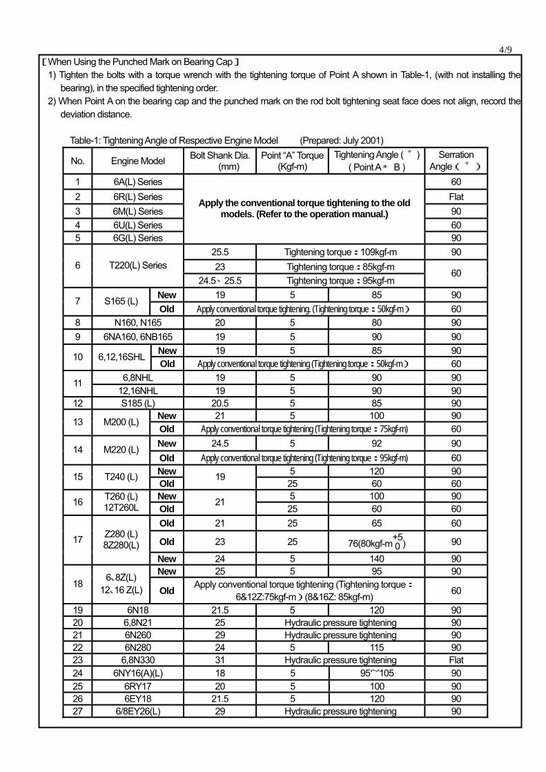
4/9 [When Using the Punched Mark on Bearing Cap] 1) Tighten the bolts with a torque wrench with the tightening torque of Point A shown in Table-1, (with not installing the
bearing), in the specified tightening order. 2) When Point A on the bearing cap and the punched mark on the rod bolt tightening seat face does not align, record the
deviation distance. Table-1: Tightening Angle of Respective Engine Model (Prepared: July 2001)
No. Engine Model Bolt Shank Dia.(mm)
Point “A” Torque(Kgf-m)
Tightening Angle ( )゚ ( Point A ⇒ B )
Serration Angle( ゜)
1 6A(L) Series 60 2 6R(L) Series Flat 3 6M(L) Series 90 4 6U(L) Series 60 5 6G(L) Series
Apply the conventional torque tightening to the old models. (Refer to the operation manual.)
90 25.5 Tightening torque:109kgf-m 90 23 Tightening torque:85kgf-m 6 T220(L) Series
24.5、25.5 Tightening torque:95kgf-m 60
New 19 5 85 90 7 S165 (L) Old Apply conventional torque tightening. (Tightening torque:50kgf-m) 60
8 N160, N165 20 5 80 90 9 6NA160, 6NB165 19 5 90 90
New 19 5 85 90 10 6,12,16SHL Old Apply conventional torque tightening (Tightening torque:50kgf-m) 60
6,8NHL 19 5 90 90 11 12,16NHL 19 5 90 90
12 S185 (L) 20.5 5 85 90 New 21 5 100 90 13 M200 (L) Old Apply conventional torque tightening (Tightening torque:75kgf-m) 60 New 24.5 5 92 90 14 M220 (L) Old Apply conventional torque tightening (Tightening torque:95kgf-m) 60 New 5 120 90 15 T240 (L) Old
19 25 60 60
New 5 100 90 16 T260 (L) 12T260L Old
21 25 60 60
Old 21 25 65 60
Old 23 25 76(80kgf-m+50 ) 90 17 Z280 (L)
8Z280(L) New 24 5 140 90 New 25 5 95 90
18 6、8Z(L) 12、16 Z(L) Old Apply conventional torque tightening (Tightening torque:
6&12Z:75kgf-m)(8&16Z: 85kgf-m) 60
19 6N18 21.5 5 120 90 20 6,8N21 25 Hydraulic pressure tightening 90 21 6N260 29 Hydraulic pressure tightening 90 22 6N280 24 5 115 90 23 6,8N330 31 Hydraulic pressure tightening Flat 24 6NY16(A)(L) 18 5 95~105 90 25 6RY17 20 5 100 90 26 6EY18 21.5 5 120 90 27 6/8EY26(L) 29 Hydraulic pressure tightening 90
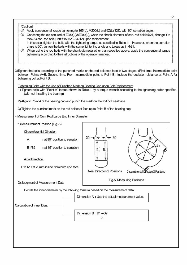
5/9 3)Tighten the bolts according to the punched marks on the rod bolt seat face in two stages: (First time: Intermediate point
between Points A~B; Second time: From intermediate point to Point B). Include the deviation distance at Point A for tightening bolt at Point B.
Tightening Bolts with the Use of Punched Mark on Bearing Cap upon Bolt Replacement
1) Tighten bolts with “Point A” torque shown in Table-1 by a torque wrench according to the tightening order specified, (with not installing the bearing).
2) Align to Point A of the bearing cap and punch the mark on the rod bolt seat face.
3) Tighten the punched mark on the rod bolt seat face up to Point B of the bearing cap.
4.Measurement of Con. Rod Large Eng Inner Diameter 1) Measurement Position (Fig.-5) Circumferential Direction A :at 90° position to serration B1/B2 :at 15° position to serration Axial Direction D1/D2:at 20mm inside from both end face 2) Judgment of Measurement Data Decide the inner diameter by the following formula based on the measurement data: Calculation of Inner Diaz.
[Caution] ① Apply conventional torque tightening to 165(L), M200(L) and 6Z(L)/12ZL with 60° serration angle. ② Concering the old con. rod of Z280(L)/8Z280(L), when the shank diameter of con. rod bolt isΦ21, change it to
theΦ23 con. rod bolt (Part #153623-23212) upon replacement. In this case, tighten the bolts with the tightening torque as specified in Table-1. However, when the serrationangle is 60°, tighten the bolts with the same tightening angle and torque as in Φ21.
③ When using the rod bolts with the shank diameter other than specified above, apply the conventional torquetightening according to the instructions of the operation manual.
Fig-5: Measuring Positions
Axial Direction 2 Positions Circumferential Direction 3 Positions
Dimension A:Use the actual measurement value.
Dimension B:B1+B2 2
6/9 Prepared: Jul. 10, 2001
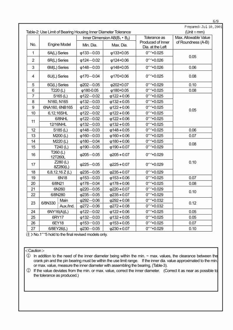
Table-2: Use Limit of Bearing Housing Inner Diameter Tolerance (Unit:mm) Inner Dimension AB(B1・B2)
No.
Engine Model Min. Dia. Max. Dia.
Tolerance as Produced of Inner
Dia. at the Left
Max. Allowable Value of Roundness (A-B)
1 6A(L) Series φ133-0.03 φ133+0.05 0~+0.025
2 6R(L) Series φ124-0.02 φ124+0.06 0~+0.026 0.05
3 6M(L) Series φ148-0.03 φ148+0.05 0~+0.026 0.06
4 6U(L) Series φ170-0.04 φ170+0.06 0~+0.025 0.08
5 6G(L) Series φ202-0.05 φ202+0.07 0~+0.029 0.10 6 T220 (L) φ180-0.05 φ180+0.05 0~+0.025 0.08 7 S165 (L) φ122-0.02 φ122+0.06 0~+0.025 8 N160, N165 φ132-0.03 φ132+0.05 0~+0.025 9 6NA160, 6NB165 φ122-0.02 φ122+0.06 0~+0.025 10 6,12,16SHL φ122-0.02 φ122+0.06 0~+0.025
6/8NHL φ122-0.02 φ122+0.06 0~+0.025 11 12/16NHL φ132-0.03 φ132+0.05 0~+0.025
0.05
12 S185 (L) φ148-0.03 φ148+0.05 0~+0.025 0.06 13 M200 (L) φ160-0.03 φ160+0.06 0~+0.025 0.07 14 M220 (L) φ180-0.04 φ180+0.06 0~+0.025 15 T240 (L) φ190-0.05 φ190+0.07 0~+0.029
0.08
16 T260 (L) 12T260L φ205-0.05 φ205+0.07 0~+0.029
17 Z280 (L) 8Z280(L) φ225-0.05 φ225+0.07 0~+0.029
18 6,8,12,16 Z (L) φ235-0.05 φ235+0.07 0~+0.029
0.10
19 6N18 φ153-0.03 φ153+0.06 0~+0.025 0.07 20 6/8N21 φ178-0.04 φ178+0.06 0~+0.025 0.08 21 6N260 φ220-0.05 φ220+0.07 0~+0.029 22 6/8N280 φ235-0.05 φ235+0.07 0~+0.029
0.10
Main φ292-0.06 φ292+0.08 0~+0.032 23 6/8N330 Aux./Ind. φ272-0.06 φ272+0.08 0~+0.032
0.12
24 6NY16(A)(L) φ122-0.02 φ122+0.06 0~+0.025 0.05 25 6RY17 φ132-0.03 φ132+0.05 0~+0.025 0.05 26 6EY18 φ153ー0.03 φ153+0.05 0~+0.025 0.07 27 6/8EY26(L) φ230-0.05 φ230+0.07 0~+0.029 0.10
注)No.1~5 hold to the final revised models only.
<Caution> ① In addition to the need of the inner diameter being within the min. ~ max. values, the clearance between the
crank pin and the pin bearing must be within the use limit range. If the inner dia. value approximated to the min.or max. value, measure the inner diameter with assembling the bearing, (Table-3).
② If the value deviates from the min. or max. value, correct the inner diameter. (Correct it as near as possible tothe tolerance as produced.)
7/9
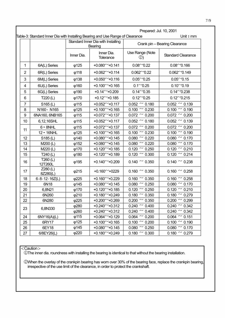
Prepared: Jul. 10, 2001 Table-3: Standard Inner Dia with Installing Bearing and Use Range of Clearance Unit:mm
Standard Inner Dia with Installing Bearing Crank pin – Bearing Clearance
Inner Dia. Inner Dia.
Tolerance Use Range (Note
②) Standard Clearance
1 6A(L) Series φ125 +0.080~+0.141 0.08~0.22 0.08~0.166
2 6R(L) Series φ118 +0.062~+0.114 0.062~0.22 0.062~0.149
3 6M(L) Series φ138 +0.050~+0.116 0.05~0.25 0.05~0.15 4 6U(L) Series φ160 +0.100~+0.165 0.1~0.25 0.10~0.19 5 6G(L) Series φ190 +0.14~+0.209 0.14~0.35 0.14~0.238 6 T220 (L) φ170 +0.12~+0.185 0.12~0.25 0.12~0.215 7 S165 (L) φ115 +0.052~+0.117 0.052 ~ 0.180 0.052 ~ 0.139 8 N160、N165 φ125 +0.100~+0.165 0.100 ~ 0.230 0.100 ~ 0.190 9 6NA160, 6NB165 φ115 +0.072~+0.137 0.072 ~ 0.200 0.072 ~ 0.200 10 6,12,16SHL φ115 +0.052~+0.117 0.052 ~ 0.180 0.052 ~ 0.139
6・8NHL φ115 +0.072~+0.137 0.072 ~ 0.200 0.072 ~ 0.200 11 12・16NHL φ125 +0.100~+0.165 0.100 ~ 0.230 0.100 ~ 0.190
12 S185 (L) φ140 +0.080~+0.145 0.080 ~ 0.220 0.080 ~ 0.170 13 M200 (L) φ152 +0.080~+0.145 0.080 ~ 0.220 0.080 ~ 0.170 14 M220 (L) φ170 +0.120~+0.185 0.120 ~ 0.250 0.120 ~ 0.210 15 T240 (L) φ180 +0.120~+0.189 0.120 ~ 0.300 0.120 ~ 0.214
16 T260 (L) 12T260L φ195 +0.140~+0.209 0.140 ~ 0.350 0.140 ~ 0.238
17 Z280 (L) 8Z280(L) φ215 +0.160~+0229 0.160 ~ 0.350 0.160 ~ 0.258
18 6・8・12・16Z(L) φ225 +0.160~+0.229 0.160 ~ 0.350 0.160 ~ 0.258 19 6N18 φ145 +0.080~+0.145 0.080 ~ 0.250 0.080 ~ 0.170 20 6,8N21 φ170 +0.120~+0.185 0.120 ~ 0.250 0.120 ~ 0.210 21 6N260 φ210 +0.180~+0.249 0.180 ~ 0.350 0.180 ~ 0.279 22 6N280 φ225 +0.200~+0.269 0.200 ~ 0.350 0.200 ~ 0.299
φ280 +0.240~+0.312 0.240 ~ 0.400 0.240 ~ 0.342 23 6,8N330 φ260 +0.240~+0.312 0.240 ~ 0.400 0.240 ~ 0.342
24 6NY16(A)(L) φ115 +0.064~+0.129 0.064 ~ 0.200 0.064 ~ 0.151 25 6RY17 φ125 +0.100~+0.165 0.100 ~ 0.200 0.100 ~ 0.190 26 6EY18 φ145 +0.080~+0.145 0.080 ~ 0.250 0.080 ~ 0.170 27 6/8EY26(L) φ220 +0.180~+0.249 0.180 ~ 0.300 0.180 ~ 0.279
<Caution> ①The inner dia. roundness with installing the bearing is identical to that without the bearing installation. ②When the overlay of the crankpin bearing has worn over 30% of the bearing face, replace the crankpin bearing,
irrespective of the use limit of the clearance, in order to protect the crankshaft.
8/9 4.Judgment of Bearing Housing Inner Dia. (Correction Standard) 1) Smaller Diameter of Whole Circumference
When the inner diameter of the whole circumference lowered the use limit value, correct the inner diameter by honing, etc. to within the standard dimensional tolerance range.
2) In the Case of Elliptical Diameter
Even when the dimension toward A and B directions represented an elliptical shape, the inner diameter can be used continuously as far as the dimension of each part and roundness remain within the use limit. However, measure the inner diameter with installing the bearing and check that the clearance to the crankpin remains within the use limit range, (Table-3).
6. Check and Repair of Serration
When the con. rod was disassembled, check the serration with Color Check, etc. that there is no cracking. If any cracking was found, repair as follows depending on the length of cracking.
1)S165(L),6 -16NHL,6N160/6N165: If the crack size is under 10mm in length and 1.0mm in depth, remove the crack with the use of a pencil grinder to prevent the progress of cracking.
2)S185(L),M200(L),M220(L):
If the crack size is under 10mm in length and 1.5mm in depth, remove the crack with the use of a pencil grinder to prevent the progress of cracking.
3)T240(L),T260(L),/12T26L,Z280(L)/8Z280(L),6N260(L),N280(L),6Z(L),12ZL:
If the crack size is under 10mm in length and 2.0mm in depth, remove the crack with the use of a pencil grinder to prevent the progress of cracking.
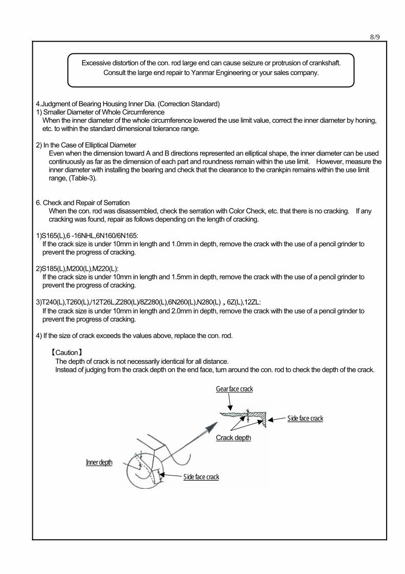
4) If the size of crack exceeds the values above, replace the con. rod. 【Caution】
The depth of crack is not necessarily identical for all distance. Instead of judging from the crack depth on the end face, turn around the con. rod to check the depth of the crack.
Excessive distortion of the con. rod large end can cause seizure or protrusion of crankshaft. Consult the large end repair to Yanmar Engineering or your sales company.
Gear face crack
Crack depth
Side face crack
Side face crack
Inner depth
9/9 7.Caution Upon Installing Con. Rod to Engine 1) Apply PROTEC GREASE or seizing inhibitor to the tightening seat face and thread of bolt and install the bolt to the cap. 2) Tighten the bolts in the bolt tightening order as follows: ・Tightening for the 1st time: up to the contact of the bolt’s seat face (Point A). ・Tightening for the 2nd time: up to the intermediate angle between Points A and B. ・Tightening for the3rd time: up to Point B (final tightening) 3) Checking after Assembly
After completing installation to the engine, check the side motion of the con. rod and check that the clearance of the bearing is normal.
8. Periodic Inspection 1) Check every year or every 6,000 hours that bolts were not loosened excessively. Re-tighten if necessary. 2) Whenever the con. rod was disassembled, check the bolt tightening by the angle tightening method. 3) Irrespective of the state of the con. rod bolts, replace the bolts every 20,000 hours.