Embed Size (px)
Citation preview
2
5.The Director (Transmission), Transmission Corp. of Andhra Pradesh Ltd., (APTRANSCO) Vidyut Soudha, Hyderabad – 500 082. FAX : 040-66665137
6. The Director ( Grid Transmission and Management), Transmission Corp. of Telangana Ltd., (TSTRANSCO) Vidyut Soudha, Khairatabad Hyderabad – 500 082. FAX : 040-23321751
7. The Member (Transmission), Kerala State Electricity Board, Vidyuthi Bhawanam, Pattom, P.B. No. 1028, Thiruvananthapuram - 695 004.
FAX : 0471-2444738
8. Member (Distribution), Tamil Nadu electricity Board (TNEB), 6th Floor, Eastern Wing, 800 Anna Salai, Chennai - 600002. FAX : 044-28516362
9. The Director (Power), Corporate Office, Block – I, Neyveli Lignite Corp. Ltd., Neyveli , Tamil Nadu – 607 801.
FAX : 04142-252650
10. The Superintending Engineer –I, First Floor, Electricity Department, Gingy Salai, Puducherry – 605 001.
FAX : 0413-2334277/2331556
11. Director (Projects), National Thermal Power Corp. Ltd. (NTPC), NTPC Bhawan, Core-7, Scope Complex, Lodhi Road, New Delhi-110003.
FAX-011-24360912
12. Director (Operations), NPCIL, 12th Floor, Vikram Sarabhai Bhawan, Anushakti Nagar, Mumbai – 400 094.
FAX : 022- 25991258
Copy to: 1. The Director (Projects),
Power Grid Corp. of India Ltd. “Saudamini”, Plot No.2, Sector-29, Gurgaon 122 001, Haryana. FAX : 95124-2571932
2. GM, SRLDC, 29, Race Course Cross Road, Bangalore 560 009 FAX – 080-22268725
3
AGENDA NOTE
Agenda Note for 37th Meeting of Standing Committee on Power System Planning in Southern Region (SCPSPSR) Date and Venue: (to be communicated shortly) 1.0 Confirmation of the minutes of previous (36th and the Joint SR-WR) meetings
of the Standing Committee
1.1 The Minutes of 36th meeting of the Standing Committee on Power System Planning of Southern Region were issued vide CEA’s letter No. 51/4/SP&PA-2013/1693-1704 dated 27th September, 2013.
1.2 Minutes of Joint Standing Committee (SR and WR): Further, a joint meeting of Standing Committee of Power System Planning of Western Region and Southern Region was held on 26th Dec, 2013 to discuss following two issues:
• Transmission system of KPTCL for evacuation of power from Yermarus(2x800MW) and Edlapur(1x800 MW) Thermal Power Generation.
• The concept on General Network Access (GNA) titled ‘Ensuring adequacy in the planning and development of Inter –state transmission network’.
1.3 The minutes of the joint meeting were issued vide CEA’s letter No 51/4/SP&PA-2014/150-171 dated 21st January, 2014. No observations were received on the circulated minutes, as such these minutes, as circulated, may be confirmed.
1.4 TANTRASNCO vide their letter no. CE/Plg&RC/ SE/SS/EE1/ AEE1/ F.36thSCM/D.454/2013 dated 25.11.2013 (copy enclosed- Annex1) has given observations on para 21.0 - Contingency Plan for evacuation of Power from ILFS, of the minutes of the 36th meeting of Standing Committee on Power System Planning of Southern Region.
1.5 In the minutes of the 36th meeting, following was agreed for Contingency Plan for evacuation of Power from ILFS (2x600 MW).
a) LILO of 2nd circuit of Neyveli – Trichy 400 kV D/C line (LILO of 1st

4
circuit already under implementation) would be carried out at Nagapattinum pooling station as contingency plan, by CTU.
b) Strengthening of Neyveli TS-II to Neyveli TS-I expansion link with higher capacity conductor as contingency plan, by CTU.
c) ILFS would be allowed to evacuate through these lines only if there are margins available in the grid.
1.6 In this connection TANTRASCO had given the observations:
“It is to be stated that, allowing IL&FS to evacuate the power by making LILO of both lines (i.e., NLC TS2 – Alundur and NLC TS1 Exp – Alundur) will over load the existing 400 kV lines at Neyveli complex. Hence, it is suggested that LILO of only one circuit Neyveli – Trichy 400 kV D/C line as agreed earlier to provide start up power to the plant may be carried out.
The evacuation system for the ILFS generation, Nagapattinum – Salem 765 S/C line & Salem – Madhugiri 765 S/c line may be speeded up to evacuate power from IL&FS.”
1.7 Members may discuss and accordingly the minutes of the 36th meeting, may be confirmed.
2.0 TANGEDCO/TANTRANSCO proposals:
2.1 Based on the joint studies carried out at Gurgaon with CEA and PGCIL on 05-03-2014 to 07-03-2014 and later on 11-06-2014 in Delhi. TNEB/TANGEDCO vide their letter no. CE/Plg&RC/SE/SS/EE1/AEE1/F.Stg Comm/D194 dated 17-06-2014 (Annex-2.1) has proposed following Intra-State transmission system.
2.2 This system will also cater to following generation projects in Tamil Nadu.
Capacity addition of 3440 MW in Chennai area by TANGEDCO:
Name Capacity CoD
a) ETPS Expansion 1x660MW 2017-18
b) Ennore SEZ (NCTPS Stage–IV) 2x660MW 2017-18
c) ETPS Replacement 1x660MW 2018-19
d ) NCTPS Stage–III 1x800MW 2018-19
5
In addition to above, OPG Power Generation Pvt. Ltd has proposed to establish coal based power plant of capacity 2x360MW in Gummidipoondi, North Chennai and they have applied connectivity to TANTRANSCO. This Generator has not signed PPA/MOU with TANGEDCO. Expected commissioning date is June 2015.
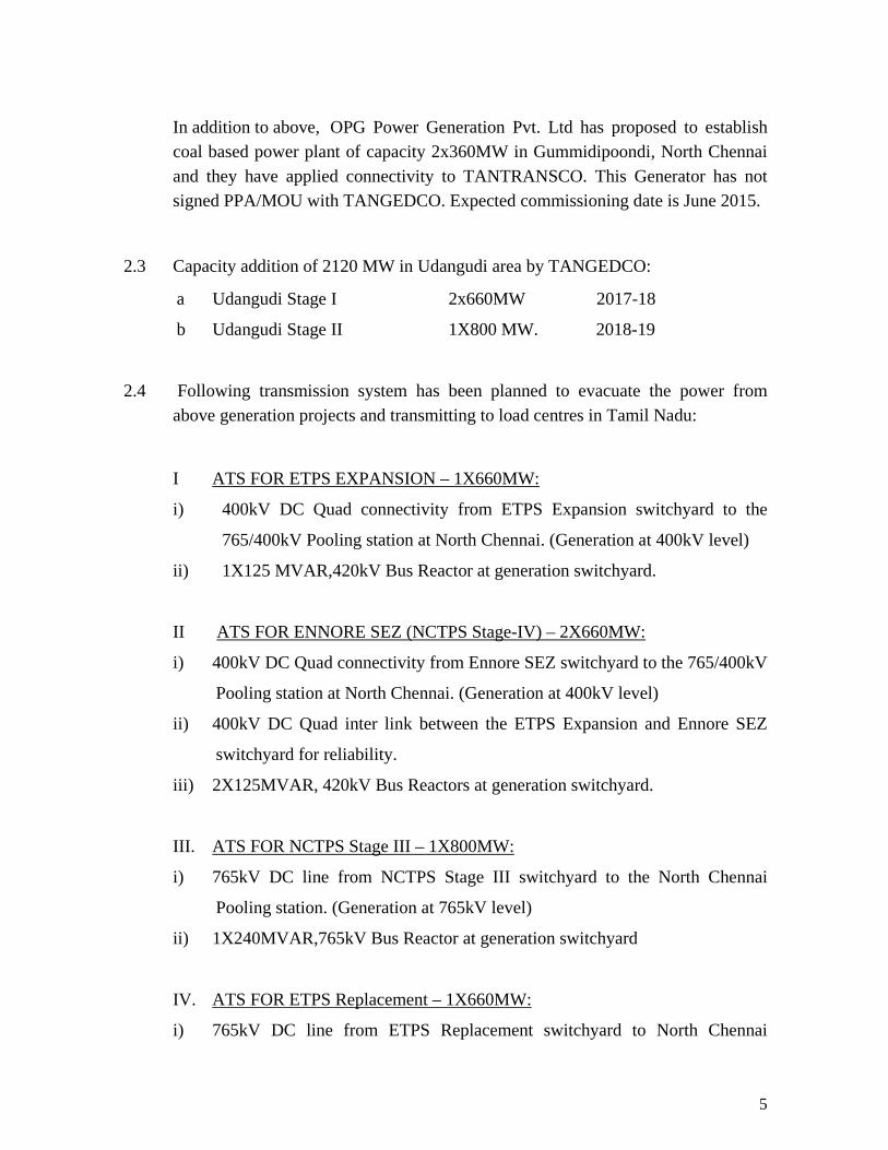
2.3 Capacity addition of 2120 MW in Udangudi area by TANGEDCO:
a Udangudi Stage I 2x660MW 2017-18
b Udangudi Stage II 1X800 MW. 2018-19
2.4 Following transmission system has been planned to evacuate the power from above generation projects and transmitting to load centres in Tamil Nadu:
I ATS FOR ETPS EXPANSION – 1X660MW:
i) 400kV DC Quad connectivity from ETPS Expansion switchyard to the
765/400kV Pooling station at North Chennai. (Generation at 400kV level)
ii) 1X125 MVAR,420kV Bus Reactor at generation switchyard.
II ATS FOR ENNORE SEZ (NCTPS Stage-IV) – 2X660MW:
i) 400kV DC Quad connectivity from Ennore SEZ switchyard to the 765/400kV
Pooling station at North Chennai. (Generation at 400kV level)
ii) 400kV DC Quad inter link between the ETPS Expansion and Ennore SEZ
switchyard for reliability.
iii) 2X125MVAR, 420kV Bus Reactors at generation switchyard.
III. ATS FOR NCTPS Stage III – 1X800MW:
i) 765kV DC line from NCTPS Stage III switchyard to the North Chennai
Pooling station. (Generation at 765kV level)
ii) 1X240MVAR,765kV Bus Reactor at generation switchyard
IV. ATS FOR ETPS Replacement – 1X660MW:
i) 765kV DC line from ETPS Replacement switchyard to North Chennai

6
Pooling station. (Generation at 765kV level)
ii) 765kV DC inter link to NCTPS Stage-III for reliability.
iii) 1X240MVAR, 765kV Bus Reactor at generation switchyard.
V. ATS for M/S.OPG Power generation Ltd.- 2X360MW : (By OPG)
i) 400kV DC line to the North Chennai Pooling station.
ii) 2X80 MVAR ,420kV Bus Reactor at the generation switchyard.
2.5 Common Transmission system for above generation projects in Chennai area:
I Establishment of 765/400kV Pooling Station in North Chennai area:
i) 3X1500MVA, 765/400kV ICTs at North Chennai Pooling station.
ii) 765kV DC connectivity from North Chennai 765kV pooling station to the
proposed Ariyalur 765/400kV SS with 240 MVAR, 765kV switchable line
reactors in each line at both ends. Another 765kV DC connectivity from
North Chennai 765kV pooling station to the proposed Ariyalur 765/400kV SS
may be reviewed at a later date depending of the commissioning of the
projects.
iii) 400kV DC line from North Chennai Pooling station to the proposed
Pulianthope 400/230kV SS.
iv) 500MVA, 400/400kV Phase Shifting transformer(PST) at the Pooling
station to control the power flow on the Pooling station – Pulianthope
400KV DC line. PST to have the capability to control power flow in both
the direction and provision to be made to bypass PST during maintenance if
required.
II Establishment of 765/400kV Sub Station in Ariyalur (near Villupuram):
i) 2X1500MVA, 765/400kV ICTs with the following 765kV and 400kV
connectivity.
ii) 765kV DC connectivity from Ariyalur 765/400kV SS to the Thiruvalam
PGCIL 765/400kV SS with 240 MVAR, 765kV switchable line reactors in
each line at both ends.

7
iii) LILO of both the circuits of Pugalur – Kalivantapattu 400kV DC Quad line at
Ariyalur. (in lieu of the approved connectivity for the Singarapet 400/230kV
SS which has been approved in the 28th Standing Committee meeting).
iv) 2X240MVAR, 765kV Bus Reactor at 765kV bus of Ariyalur 765/400kV SS.
Provision for 420kV bus reactor at 400kV bus for future requirement if
needed depending on actual field condition.
III Establishment of 765/400kV SS in Coimbatore Region
i) 2X1500MVA, 765/400kV ICTs with the following 765kV and 400kV
connectivity.
ii) 765kV DC connectivity to the proposed Ariyalur 765/400kV SS with 240
MVAR, 765kV switchable line reactors in each line at both ends.
iii) 400kV DC connectivity to the sanctioned Edayarpalayam 400/230KV SS.
iv) 400KV DC connectivity to sanctioned Rasipalayam 400/230KV SS.
v) 2X240 MVAR, 765kV bus Reactors at 765kV bus of Coimbatore 765/400kV
SS. Provision for bus reactor at 400kV bus for future requirement if needed
depending on the actual field condition.
2.6 ATS for proposed power plants at Udangudi (2x660 MW + 1x 800MW)
i) 400kV DC Quad line to the Kayathar 400kV SS.
ii) 400kV DC line to the proposed Samugarengapuram 400/230-110 kV SS.
iii) 400kV Quad DC line to the proposed Ottapidaram 400/230-110KV SS.
The following two substations are required as system strengthening for the
Udangudi projects:
I) Ottapidaram 400/230-110 KV Substation with 2x 315MVA, 400/230kV ICTs
and 2x200 MVA, 400/110kV ICTs with the following 400kV connectivity.
a. 400 KV D/C Quad line from Udangudi Switchyard.
b. 400 KV D/C Quad line to Kamuthi 400/230-110 KV Substation.
230kV connectivity:
o LILO of TSipcot – Kavanoor 230kV SC line.
8
o 230kV DC line from Indbharath generation switchyard of 2x150 MW.
o LILO of TSipcot – Savasapuram 230kV SC feeder.
II) Kamuthi 400/230-110 KV Substation for Solar Power injection (maximum
1000 MW) with 3x 315MVA 400/230kV ICTs and 2x200 MVA, 400/110kV
ICTs with 400 KV DC Quad line from Kamudhi SS to the existing Karaikudi
400kV PGCIL Substation.
230kV connectivity:
o 230kV DC line to the proposed Muthuramalingapuram 230kV SS.
o 230kV DC line to the existing Kavanoor 230kV SS.
2.7 TANTRANSCO has proposed to establish the following 400 KV Substations, as System strengthening, throughout TamilNadu within the end of 13th plan.
(i) Samugarengapuram 400/230-110 KV wind Substation with 2x 315MVA, 400/230kV ICTs and 2x200 MVA, 400/110kV ICTs with 400 KV D/C line from Udangudi Switchyard. In Aralvaimozhi pass wind area of southern part of TN, the existing wind capacity is 1800MW and there is no 400kV substation available. To avoid the existing congestion and to accommodate the future wind addition (maximum 300 MW) and for load drawal during non wind season Samugarengapuram 400/230-110kV SS is proposed. The following 230kV connectivity is proposed:
o LILO of Kudankulam – SRPudur 230kV SC line
o LILO of Udayathur – Sankaneri 230kV SC line
o 230kV DC line to proposed Muppandal 230kV SS.
(ii) Pudukottai 400/230-110 KV Substation for load drawal with 2x 315MVA, 400/230kV ICTs and 2x200 MVA, 400/110kV ICTs with LILO of both 400 KV Karaikudi – Pugalur TANTRANSCO DC Quad line.
230kV connectivity:
o 230kV SC line to Karambium 230kV SS.
o 230kV SC line to Pudukottai 230kV SS.
o 230kV SC line to proposed Tuvakudi (BHEL) 230kV SS.
(iii) Turaiyur 400/230 KV Substation for load drawal with 2x 315MVA, 400/230kV ICTs with LILO of one of the NLC – Pugalur 400 KV PGCIL line, and 400 KV D/C line to the proposed Mangalapuram 400 KV Substation.
9
230kV connectivity:
o 230kV SC line to Perambalur 230kV SS.
o 230kV SC line to Samayapuram 230kV SS.
o 230kV SC line to sanctioned Jambunathapuram 230kV SS
o 230kV SC line to the sanctioned Poyyur 230kV SS
(iv) Kolapalur 400/230-110 KV Substation with 2x 315MVA 400/230kV ICTs and 2x200 MVA, 400/110kV ICTs with LILO of one of the 400 KV MTPS Stage III – Karamadai TANTRANSCO line, and 400 KV D/C line from Rasipalayam 400 KV Substation.
230kV connectivity:
o 230kV SC line to Thingalur 230kV SS.
o 230kV SC line to Anthiyur 230kV SS.
o 230kV SC line to Shenbagapudur 230kV SS.
o LILO of Gobi – Pallakapalayam 230kV feeder
o LILO of Karamadai – Ingur 230kV line
(v) Mangalapuram 400/230 KV Substation with 2x 315MVA, 400/230kV ICTs with LILO of both the Ariyalur – Pugalur 400 KV D/C Quad line.
230kV connectivity:
o LILO of Salem – Singapuram
o LILO of Deviakurichi – Valayapatty 230kV feeder.
o 230kV SC line to the proposed Thammampatty 230kV SS
o 230kV SC line to the proposed Udayapatty 230kV SS.
(vi) Sholingur 400/230-110 KV Substation with 2x 315MVA, 400/230kV ICTs and 2x200 MVA, 400/110kV ICTs with LILO of Sriperumbudur- Tiruvalam - Kolar 400 KV S/C PGCIL line. (In between Sriperumbudur & Tiruvalam 400 KV Substation)
230kV connectivity:
o LILO of Thiruvalam – Mosur 230kV feeder
o LILO of SVChatram – Arni 230kV feeder
o 230kV DC line to the proposed Pattaraiperumbudur 230kV SS.
(vii) Pulianthope 400/230 KV Substation with 3x 315MVA, 400/230kV ICTs with 400kV DC Quad line from the proposed North Chennai Pooling Station and 400 kV DC line from Manali 400/230-110 KV Substation.
10
230kV connectivity:
o 230kv SC cable link to Tondiarpet, Basinbridge and sanctioned Vysarpadi
&CMRL Central 230kV substations which are under execution.
(viii) Mylapore 400/230 KV Substation with 2x 315MVA, 400/230kV ICTs with 400 KV SC cable from proposed Pulianthope 400/230 KV Substation and 400 KV SC cable to Guindy 400 KV Substation. (Upgradation of existing Mylapore 230/110kV SS).
(ix) Palavadi 400/230-110 KV Substation: For the already sanctioned Singarapet 400KV Substation, the land has now been identified at Palavadi near Salem 765/400 KV PGCIL Substation with 400 KV DC quad line from MTPS Stage III and 400KV DC quad line from Tiruvalam 400 KV Substation and 400 quad 2XDC line from Rasipalayam 400 KV Substation (One DC line via Salem 765/400 KV Substation).
230kV connectivity:
o LILO of Karimangalam - MALCO 230kV SC line
o 230kV link line to the sanctioned Gurubarahally 230kV SS.
o 230kV DC link line to the sanctioned Udanapally 230kV substation.
2.8 Kayathar – Koilpatty (Tuticorin Pooling point) 400kV DC Quad line:
Kayathar – Koilpatty (Tuticorin Pooling point) 400kV DC Quad line for additional connectivity with ISTS and increased reliability purpose.
2.9 Pavoorchatram 400kV SS (Tennampatty 400kV SS):
For the Thenampatty 400/230-110kV SS which has been approved in the 34th Standing committee meeting, now the land has been identified near Pavoorchatram. The 400kV connectivity is as decided in the 34th Standing committee meeting i.e. 400kV DC line to Kayathar 400kV SS.
230kV connectivity:
o LILO of Kodikurichi – Veeranam 230kV line in addition to the connectivity
to new wind substations.
2.10 The above system is depicted in a diagram given at Annex- 2.2. Members may discuss.
11
3.0 Constraints in 400kV bays extensions at 400kV Vemagiri S/S.
3.1 APTRANSCO vide their letter no. CE (PS)/SE (SP)/ DE (SS)/F. Hinduja/D. No. 57/2014 dated 28.03.2014 (copy enclosed at Annex-3.1) has informed that there is space constraints at their Vemagiri 400 kV substation and it has become difficult to provide bay extension there. Therefore, there is difficulty in bringing the KVKota-Vemagiri 400 kV DC line at Vemagiri. This line was agreed 36th meeting of the Standing Committee, as part of the transmission system for evacuation of power from 1040 MW M/s Hinduja (HNPCL) Power Project.
3.2 As a solution, they have proposed to remove LILO at 400 kV Vemagiri Substation and make through one circuit of 400 kV Simhadri-II – Nunna DC line (PGCIL) LILOed at 400kV Vemagiri SS.
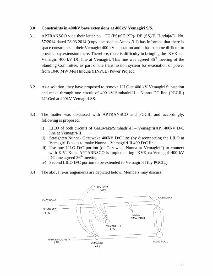
3.3 The matter was discussed with APTRANSCO and PGCIL and accordingly, following is proposed:
i) LILO of both circuits of Gazuwaka/Simhadri-II – Vemagiri(AP) 400kV D/C line at Vemagiri-II.
ii) Straighten Nunna- Gazuwaka 400kV D/C line (by disconnecting the LILO at Vemagiri-I) so as to make Nunna – Vemagriri-II 400 D/C link
iii) Use one LILO D/C portion (of Gazuwaka-Nunna at Vemagiri-I) to connect with K.V. Kota. APTARNSCO is implementing KVKota-Vemagiri 400 kV DC line agreed 36th meeting.
iv) Second LILO D/C portion to be extended to Vemagiri-II (by PGCIL)
3.4 The above re-arrangements are depicted below. Members may discuss.
K V KOTA
SIMANDRI-II
VEMAGIRI- II
VEMAGIRI - I VIZAG POOL
GAZUWAKAVIJAYWADA
NARAYAROO OETA
NUNNA (PG)
( AP )
( PG )
( AP )
( AP )
( PG )
12
4.0 System for increasing capacity of Inter-State Transmission system for import
of power into SR up to 2018-19. 4.1 Presently, Southern Region is facing power deficit which is of the order of 3500
MW (as per CEAs monthly report on power supply position). This situation has arisen mainly due to – (i) delay/deferment of anticipated generation projects, for example, Krishnapattam UMPP (4000 MW), Cheyyur UMPP(4000 MW), Udangudi TPS(---MW), IPP projects in Nagapatanam/ Cuddalore area (3000 to 4000 MW), Kundankulam APP (2000 MW), Kalpakkam PFPR (500 MW), East cost project in Srikakulam (1320 MW), Gas based projects in Vemagiri (about 3000 MW) etc. and (ii) also due to non-availability of gas for existing gas projects in Southern Region.
Some of the constraints in import of power into Southern Region and delivering up to Kerala and Tamil Nadu has also been due to long delay in commissioning of important 400 kV transmission lines, for example, Mysore - Kozikode 400 kV D/C line (delayed by more than 7 years), Tirunelveli-Edamon-Cochin 400 kV D/c line (delayed by about 4 years) and Narendera-Kolhapur inter-regional 765 kV D/C line. Some constraints have also been caused due to delay in the transmission systems of states, for example, the system associated with Narsaropeta, Vijaywada-Hyderabad & Kakatiya TPS in Andhra Pradesh, system associated with Yermarus TPS and non-finalisation of land for New Narendera in Karnataka and transmission system for wind projects and North Chennai TPS in Tamil Nadu.
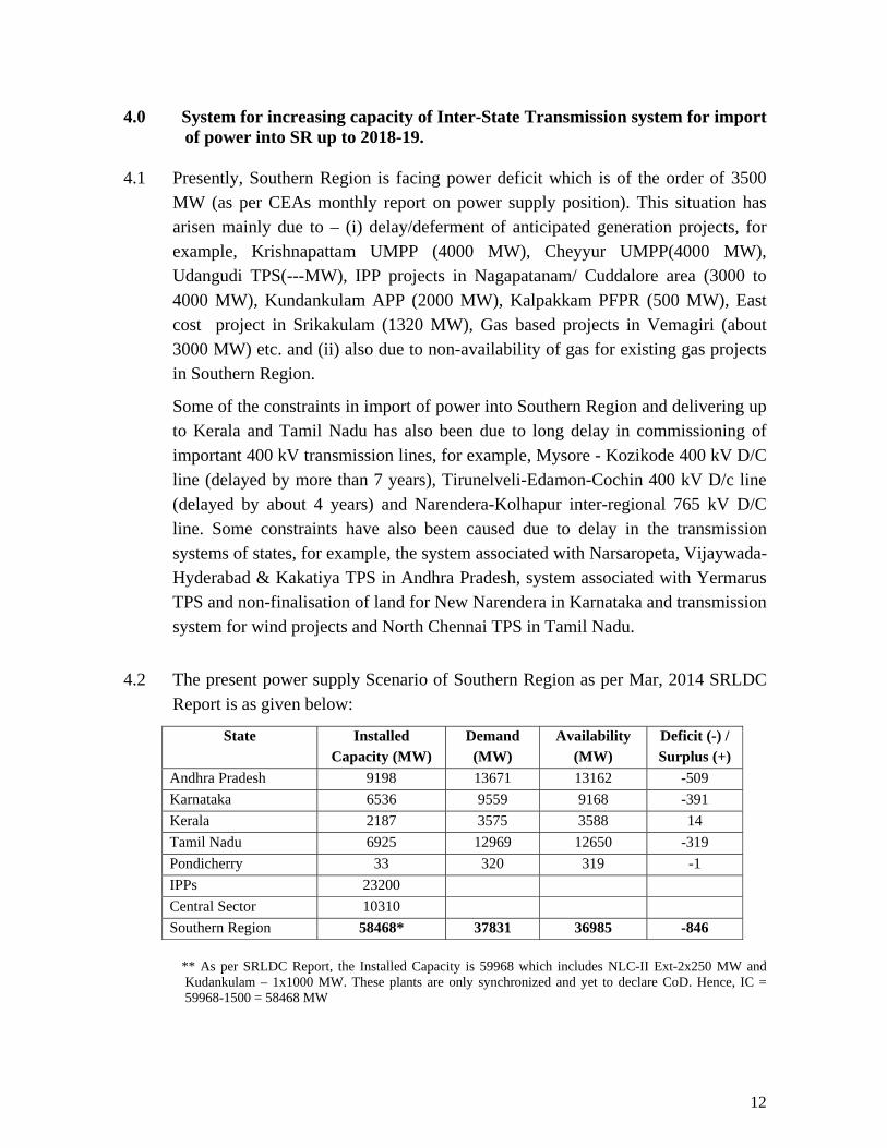
4.2 The present power supply Scenario of Southern Region as per Mar, 2014 SRLDC
Report is as given below:
State Installed Capacity (MW)
Demand (MW)
Availability (MW)
Deficit (-) / Surplus (+)
Andhra Pradesh 9198 13671 13162 -509 Karnataka 6536 9559 9168 -391 Kerala 2187 3575 3588 14 Tamil Nadu 6925 12969 12650 -319 Pondicherry 33 320 319 -1 IPPs 23200 Central Sector 10310 Southern Region 58468* 37831 36985 -846
** As per SRLDC Report, the Installed Capacity is 59968 which includes NLC-II Ext-2x250 MW and Kudankulam – 1x1000 MW. These plants are only synchronized and yet to declare CoD. Hence, IC = 59968-1500 = 58468 MW
13
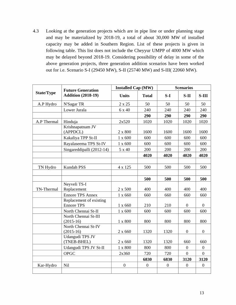
4.3 Looking at the generation projects which are in pipe line or under planning stage
and may be materialized by 2018-19, a total of about 30,000 MW of installed capacity may be added in Southern Region. List of these projects is given in following table. This list does not include the Cheyyur UMPP of 4000 MW which may be delayed beyond 2018-19. Considering possibility of delay in some of the above generation projects, three generation addition scenarios have been worked out for i.e. Scenario S-I (29450 MW), S-II (25740 MW) and S-III( 22060 MW).
State/Type Future Generation Addition (2018-19)
Installed Cap (MW) Scenarios
Units Total S-I S-II S-III
A.P Hydro N'Sagar TR 2 x 25 50 50 50 50 Lower Jurala 6 x 40 240 240 240 240 290 290 290 290
A.P Thermal Hinduja 2x520 1020 1020 1020 1020
Krishnapatnam JV (APPDCL) 2 x 800 1600 1600 1600 1600
Kakaliya TPP St-II 1 x 600 600 600 600 600 Rayalaseema TPS St-IV 1 x 600 600 600 600 600 Singareddipalli (2012-14) 5 x 40 200 200 200 200 4020 4020 4020 4020
TN Hydro Kundah PSS 4 x 125 500 500 500 500
500 500 500 500
TN-Thermal Neyveli TS-I Replacement 2 x 500 400 400 400 400
Ennore TPS Annex 1 x 660 660 660 660 660
Replacement of existing Ennore TPS 1 x 660 210 210 0 0
North Chennai St-II 1 x 600 600 600 600 600
North Chennai St-III (2015-16) 1 x 800 800 800 800 800
North Chennai St-IV (2015-16) 2 x 660 1320 1320 0 0
Udangudi TPS JV (TNEB-BHEL) 2 x 660 1320 1320 660 660
Udangudi TPS JV St-II 1 x 800 800 800 0 0 OPGC 2x360 720 720 0 0
6830 6830 3120 3120 Kar-Hydro Nil 0 0 0 0 0
14
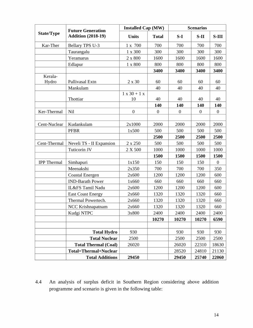
State/Type Future Generation Addition (2018-19)
Installed Cap (MW) Scenarios
Units Total S-I S-II S-III
Kar-Ther Bellary TPS U-3 1 x 700 700 700 700 700 Taurangalu 1 x 300 300 300 300 300 Yeramarus 2 x 800 1600 1600 1600 1600 Edlapur 1 x 800 800 800 800 800
3400 3400 3400 3400 Kerala- Hydro Pallivasal Extn 2 x 30 60 60 60 60
Mankulam 40 40 40 40
Thottiar 1 x 30 + 1 x
10 40 40 40 40 140 140 140 140 Ker-Thermal Nil 0 0 0 0 0
Cent-Nuclear Kudankulam 2x1000 2000 2000 2000 2000
PFBR 1x500 500 500 500 500 2500 2500 2500 2500 Cent-Thermal Neveli TS - II Expansion 2 x 250 500 500 500 500
Tuticorin JV 2 X 500 1000 1000 1000 1000 1500 1500 1500 1500 IPP Thermal Simhapuri 1x150 150 150 150 0
Meenakshi 2x350 700 700 700 350 Coastal Energen 2x600 1200 1200 1200 600 IND-Barath Power 1x660 660 660 660 660 IL&FS Tamil Nadu 2x600 1200 1200 1200 600 East Coast Energy 2x660 1320 1320 1320 660 Thermal Powertech. 2x660 1320 1320 1320 660 NCC Krishnapatnam 2x660 1320 1320 1320 660 Kudgi NTPC 3x800 2400 2400 2400 2400 10270 10270 10270 6590 Total Hydro 930 930 930 930 Total Nuclear 2500 2500 2500 2500 Total Thermal (Coal) 26020 26020 22310 18630 Total=Thermal+Nuclear 28520 24810 21130 Total Additions 29450 29450 25740 22060
4.4 An analysis of surplus deficit in Southern Region considering above addition programme and scenario is given in the following table:
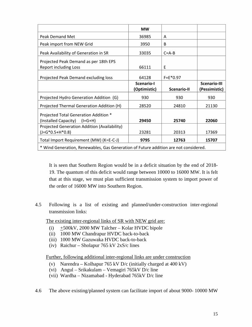
15
MW Peak Demand Met 36985 A
Peak import from NEW Grid 3950 B
Peak Availability of Generation in SR 33035 C=A‐B
Projected Peak Demand as per 18th EPS Report including Loss 66111 E
Projected Peak Demand excluding loss 64128 F=E*0.97
Scenario‐I (Optimistic) Scenario‐II
Scenario‐III (Pessimistic)
Projected Hydro Generation Addition (G) 930 930 930
Projected Thermal Generation Addition (H) 28520 24810 21130
Projected Total Generation Addition * (Installed Capacity) (I=G+H) 29450 25740 22060 Projected Generation Addition (Availability) (J=G*0.5+H*0.8) 23281 20313 17369
Total Import Requirement (MW) (K=E‐C‐J) 9795 12763 15707
* Wind Generation, Renewables, Gas Generation of Future addition are not considered. It is seen that Southern Region would be in a deficit situation by the end of 2018-
19. The quantum of this deficit would range between 10000 to 16000 MW. It is felt that at this stage, we must plan sufficient transmission system to import power of the order of 16000 MW into Southern Region.
4.5 Following is a list of existing and planned/under-construction inter-regional transmission links:
The existing inter-regional links of SR with NEW grid are: (i) +500kV, 2000 MW Talcher – Kolar HVDC bipole (ii) 1000 MW Chandrapur HVDC back-to-back (iii) 1000 MW Gazuwaka HVDC back-to-back (iv) Raichur – Sholapur 765 kV 2xS/c lines
Further, following additional inter-regional links are under construction (v) Narendra – Kolhapur 765 kV D/c (initially charged at 400 kV) (vi) Angul – Srikakulam – Vemagiri 765kV D/c line (vii) Wardha – Nizamabad - Hyderabad 765kV D/c line
4.6 The above existing/planned system can facilitate import of about 9000- 10000 MW
16
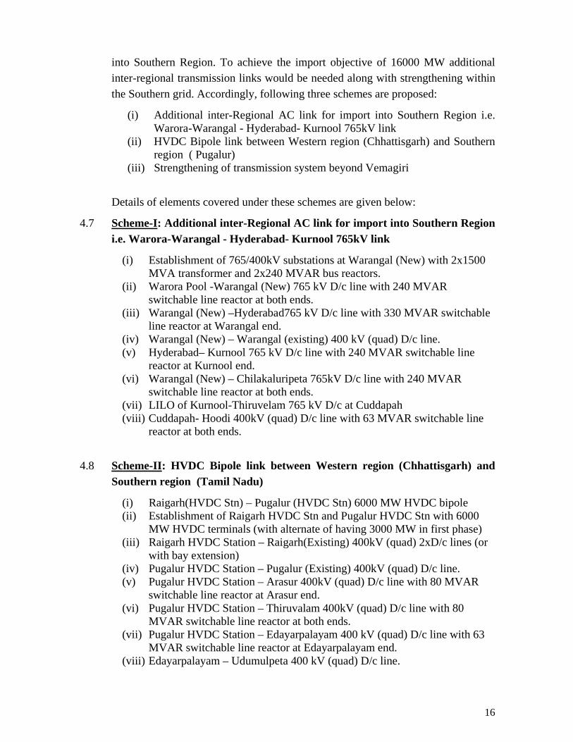
into Southern Region. To achieve the import objective of 16000 MW additional inter-regional transmission links would be needed along with strengthening within the Southern grid. Accordingly, following three schemes are proposed:
(i) Additional inter-Regional AC link for import into Southern Region i.e. Warora-Warangal - Hyderabad- Kurnool 765kV link
(ii) HVDC Bipole link between Western region (Chhattisgarh) and Southern region ( Pugalur)
(iii) Strengthening of transmission system beyond Vemagiri
Details of elements covered under these schemes are given below:
4.7 Scheme-I: Additional inter-Regional AC link for import into Southern Region i.e. Warora-Warangal - Hyderabad- Kurnool 765kV link
(i) Establishment of 765/400kV substations at Warangal (New) with 2x1500 MVA transformer and 2x240 MVAR bus reactors.
(ii) Warora Pool -Warangal (New) 765 kV D/c line with 240 MVAR switchable line reactor at both ends.
(iii) Warangal (New) –Hyderabad765 kV D/c line with 330 MVAR switchable line reactor at Warangal end.
(iv) Warangal (New) – Warangal (existing) 400 kV (quad) D/c line. (v) Hyderabad– Kurnool 765 kV D/c line with 240 MVAR switchable line
reactor at Kurnool end. (vi) Warangal (New) – Chilakaluripeta 765kV D/c line with 240 MVAR
switchable line reactor at both ends. (vii) LILO of Kurnool-Thiruvelam 765 kV D/c at Cuddapah (viii) Cuddapah- Hoodi 400kV (quad) D/c line with 63 MVAR switchable line
reactor at both ends.
4.8 Scheme-II: HVDC Bipole link between Western region (Chhattisgarh) and Southern region (Tamil Nadu)
(i) Raigarh(HVDC Stn) – Pugalur (HVDC Stn) 6000 MW HVDC bipole (ii) Establishment of Raigarh HVDC Stn and Pugalur HVDC Stn with 6000
MW HVDC terminals (with alternate of having 3000 MW in first phase) (iii) Raigarh HVDC Station – Raigarh(Existing) 400kV (quad) 2xD/c lines (or
with bay extension) (iv) Pugalur HVDC Station – Pugalur (Existing) 400kV (quad) D/c line. (v) Pugalur HVDC Station – Arasur 400kV (quad) D/c line with 80 MVAR
switchable line reactor at Arasur end. (vi) Pugalur HVDC Station – Thiruvalam 400kV (quad) D/c line with 80
MVAR switchable line reactor at both ends. (vii) Pugalur HVDC Station – Edayarpalayam 400 kV (quad) D/c line with 63
MVAR switchable line reactor at Edayarpalayam end. (viii) Edayarpalayam – Udumulpeta 400 kV (quad) D/c line.
17
(ix) Establishment of 400/220kV substation with 2x500 MVA transformers at Edayarpalayam and 2x125 MVAR bus reactors.
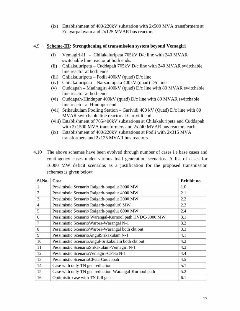
4.9 Scheme-III: Strengthening of transmission system beyond Vemagiri
(i) Vemagiri-II – Chilakaluripeta 765kV D/c line with 240 MVAR switchable line reactor at both ends.
(ii) Chilakaluripeta – Cuddapah 765kV D/c line with 240 MVAR switchable line reactor at both ends.
(iii) Chilakaluripeta – Podli 400kV (quad) D/c line (iv) Chilakaluripeta – Narsaraopeta 400kV (quad) D/c line (v) Cuddapah – Madhugiri 400kV (quad) D/c line with 80 MVAR switchable
line reactor at both ends. (vi) Cuddapah-Hindupur 400kV (quad) D/c line with 80 MVAR switchable
line reactor at Hindupur end. (vii) Srikaukulam Pooling Station – Garividi 400 kV (Quad) D/c line with 80
MVAR switchable line reactor at Garividi end. (viii) Establishment of 765/400kV substations at Chilakaluripeta and Cuddapah
with 2x1500 MVA transformers and 2x240 MVAR bus reactors each. (ix) Establishment of 400/220kV substations at Podli with 2x315 MVA
transformers and 2x125 MVAR bus reactors.
4.10 The above schemes have been evolved through number of cases i.e base cases and contingency cases under various load generation scenarios. A list of cases for 16000 MW deficit scenarios as a justification for the proposed transmission schemes is given below:
Sl.No. Case Exhibit no. 1 Pessimistic Scenario Raigarh-pugalur 3000 MW 1.0 2 Pessimistic Scenario Raigarh-pugalur 4000 MW 2.1 3 Pessimistic Scenario Raigarh-pugalur 2000 MW 2.2 4 Pessimistic Scenario Raigarh-pugalur0 MW 2.3 5 Pessimistic Scenario Raigarh-pugalur 6000 MW 2.4 6 Pessimistic Scenario Warangal-Kurnool path HVDC-3000 MW 3.1 7 Pessimistic ScenarioWarora-Warangal N-1 3.2 8 Pessimistic ScenarioWarora-Warangal both ckt out 3.3 9 Pessimistic ScenarioAngulSrikakulam N-1 4.1 10 Pessimistic ScenarioAngul-Srikakulam both ckt out 4.2 11 Pessimistic ScenarioSrikakulam-Vemagiri N-1 4.3 12 Pessimistic ScenarioVemagiri-CPeta N-1 4.4 13 Pessimistic ScenarioCPeta-Cudappah 4.5 14 Case with only TN gen reduction 5.1 15 Case with only TN gen reduction-Warangal-Kurnool path 5.2 16 Optimistic case with TN full gen 6.1
18
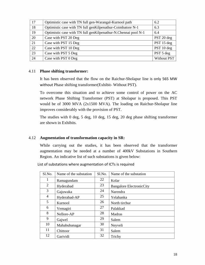
17 Optimistic case with TN full gen-Warangal-Kurnool path 6.2 18 Optimistic case with TN full genKilpenathur-Coimbatore N-1 6.3 19 Optimistic case with TN full genKilpenathur-N.Chennai pool N-1 6.4 20 Case with PST 20 Deg PST 20 deg 21 Case with PST 15 Deg PST 15 deg 22 Case with PST 10 Deg PST 10 deg 23 Case with PST 5 Deg PST 5 deg 24 Case with PST 0 Deg Without PST
4.11 Phase shifting transformer:
It has been observed that the flow on the Raichur-Sholapur line is only 565 MW
without Phase shifting transformer(Exhibit- Without PST).
To overcome this situation and to achieve some control of power on the AC network Phase Shifting Transformer (PST) at Sholapur is proposed. This PST would be of 3000 MVA (2x1500 MVA). The loading on Raichur-Sholapur line improves considerably with the provision of PST.
The studies with 0 deg, 5 deg, 10 deg, 15 deg, 20 deg phase shifting transformer are shown in Exhibits.
4.12 Augmentation of transformation capacity in SR:
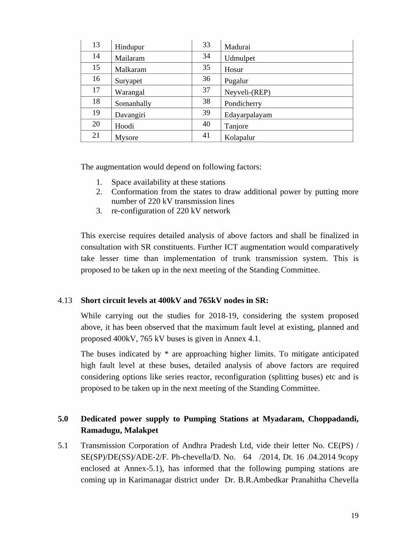
While carrying out the studies, it has been observed that the transformer augmentation may be needed at a number of 400kV Substations in Southern Region. An indicative list of such substations is given below:
List of substations where augmentation of ICTs is required
Sl.No. Name of the substation Sl.No. Name of the substation 1 Ramagundam 22 Kolar 2 Hyderabad 23 Bangalore ElectronicCity 3 Gajuwaka 24 Narendra 4 Hyderabad-AP 25 Yelahanka 5 Kurnool 26 North tirchur 6 Vemagiri 27 Palakkad 8 Nellore-AP 28 Madras 9 Gajwel 29 Salem 10 Mahabubanagar 30 Neyveli 11 Chittoor 31 Salem 12 Garividi 32 Trichy
19
13 Hindupur 33 Madurai 14 Mailaram 34 Udmulpet 15 Malkaram 35 Hosur 16 Suryapet 36 Pugalur 17 Warangal 37 Neyveli-(REP) 18 Somanhally 38 Pondicherry 19 Davangiri 39 Edayarpalayam 20 Hoodi 40 Tanjore 21 Mysore 41 Kolapalur
The augmentation would depend on following factors:
1. Space availability at these stations 2. Conformation from the states to draw additional power by putting more
number of 220 kV transmission lines 3. re-configuration of 220 kV network
This exercise requires detailed analysis of above factors and shall be finalized in consultation with SR constituents. Further ICT augmentation would comparatively take lesser time than implementation of trunk transmission system. This is proposed to be taken up in the next meeting of the Standing Committee.
4.13 Short circuit levels at 400kV and 765kV nodes in SR:
While carrying out the studies for 2018-19, considering the system proposed above, it has been observed that the maximum fault level at existing, planned and proposed 400kV, 765 kV buses is given in Annex 4.1.
The buses indicated by * are approaching higher limits. To mitigate anticipated high fault level at these buses, detailed analysis of above factors are required considering options like series reactor, reconfiguration (splitting buses) etc and is proposed to be taken up in the next meeting of the Standing Committee.
5.0 Dedicated power supply to Pumping Stations at Myadaram, Choppadandi, Ramadugu, Malakpet
5.1 Transmission Corporation of Andhra Pradesh Ltd, vide their letter No. CE(PS) / SE(SP)/DE(SS)/ADE-2/F. Ph-chevella/D. No. 64 /2014, Dt. 16 .04.2014 9copy enclosed at Annex-5.1), has informed that the following pumping stations are coming up in Karimanagar district under Dr. B.R.Ambedkar Pranahitha Chevella

20
Sujala Project lift scheme.
i) Myadaram, Karimnagar Dt. (Pkg-6) – 756 MW
ii) Choppadandi, Karimnagar Dt. (Pkg-7) – 150 MW
iii) Ramadugu, Karimnagar Dt. (Pkg-8) – 720 MW
iv) Malakpet, Karimnagar Dt. (Pkg-9) - 30 MW
v) Tippapur, Karimnagar Dt. (Pkg-10) - 336 MW
5.2 TSTRANSCO (Transmission company of Telangana) has informed that this project is designed to utilize 160 tmcft of Pranahita water and serve 16.4 lakh acres in the water scarcity areas of Adilabad, Karimnagar, Warangal, Nizamabad, Nalgonda, Medak and Ranga Reddy districts. The water from this Pranahitha barrage will be transferred into the reservoir of the Yellampalli project already constructed across the Godavari, before being released to the intended areas, including Hyderabad city (30 tmcft) for drinking purpose. TSTRANSCO has informed that motors would be synchronous motors to pump with average 530 meters average pumping head . These alternating current motors will run between 0.95 pf lead or lag. The packages under this project are:
a) Package-6: voltage rating is 13.8 kV with 6 pumps with the total power
requirement of 750 MW b) Package-7: voltage rating is 11 kV with 3 pumps with the total power
requirement of 123 MW c) Package-8: voltage rating is 13.8 kV with 5 pumps with the total power
requirement of 670 MW d) Package-10: voltage rating is 13.8 kV with 8 pumps with the total power
requirement of 336 MW
5.3 Accordingly, the following transmission scheme for extension of supply to the above packages of Dr. B.R. Ambedkar Pranahita – Chevella Sujala Sravanti Lift Irrigation Scheme has been proposed by TSTRANSCO:
a) Erection of 400kV SS at Ramadugu (Pkg-8).
b) Erection of 400kV Sub-Station at Choppadandi (Pkg-7) with 2x315 MVA
ICTs.
c) Erection of 400kV SS at Myadaram (Pkg-6)
d) Erection of 400kV SS at Tippapur (Pkg-10)
21
e) Erection of a 132kV SS at Malakpet (Pkg-9)
f) Erection of 400kV Quad Moose DC line for making LILO of both the
circuits of 400kV SCCL – Gajwel Quad Moose DC Line at the proposed
400kV Ramadugu SS (total 50kM for two LILO DC lines).
g) Erection of 90kM 400kV Twin Moose DC line from 400kV Dichpally SS
to the proposed 400kV Ramadugu SS.
h) Erection of 25kM 400kV Quad Moose DC line from 400kV Ramadugu SS
to 400kV Myadaram SS.
i) Erection of 25kM 400kV Quad Moose DC line from 400kV Ramadugu SS
to 400kV Choppadandi SS.
j) Erection of 40kM 400kV Twin Moose DC line from 400kV Choppadandi
SS to 400kV Tippapur SS.
k) Erection of 400kV Twin Moose DC line for making LILO of both the
circuits of 400kV KTPP – Gajwel Twin Moose DC Line at the proposed
400kV Tippapur SS (total 80kM for two LILO DC lines).
l) Erection of 60kM 400kV Twin Moose DC line from 400kV Dichpally SS
to the upcoming 400kV Nirmal SS.
m) Erection of 30kM 132kV DC line from 220kV Jagityala SS to the proposed
132kV Malakpet SS.
5.4 SLD showing above system is given at Annex-5.2. The load flow result considering all pumps running on full load and pumps running on no load are given at Annex -5.2.
5.5 TSTRANSCO to present their proposal. Members may discuss.
6.0 400kV Bays in Dharmapuri (Salem) 765/400kV SS for terminating 400kV DC line from Rasipalayam 400kV SS:
6.1 During the 34th Standing Committee Meeting (para 3.7(b)) for Southern Region, following transmission system was inter-alia agreed for evacuation of wind power projects in Tamil Nadu
System for additional inter-connection with ISTS and increased reliability:

22
i) LILO of one Rasipalayam -Singarapet 400kV D/c line at Salem 765/400kV (POWERGRID) substation
6.2 TNEB vide their letter no Lr.No. CE/Plg.&R.C/SE/SS/EE1/AEE1/F.400kV Bays/D.202/14 Dated. 21.06.14 copy at Annex 6.1) has stated that as per PGCIL there are no bays available at Dharmapuri substation for TANTRANSCO now, and at a later stage when the operating voltage is at 765kV level, 400kV bays will get released.
6.3 TNEB has also informed that Thappagudu- Anaikadavu- Rasipalayam 400kV D/C line with 400kV S/S is on the fast track. The land for the Singarapet 400kV SS has been identified near Salem (Dharmapuri) 765kV PGCIL SS i.e., at Palavady., and the work is expected to be taken up shortly. Out of the 2 DC 400kV circuits from Rasipalayam to Palavady (Singarapet). One DC circuit has been already taken up and the other DC circuit is included in the KfW funding.
6.4 TNEB has requested that at least one of the Rasipalayam – Palavady 400kV line, the execution of which is on the fast track may be permitted to be made LILO at Dharmapuri. They have suggested that the two numbers 400kV Bays meant for ICTs in the Salem 765kV SS may be temporarily permitted to be used for making LILO of the above said line.
6.5 TNEB/TANTRANSCO may present the proposal. Members may discuss.
7.0 Transmission System for evacuation of power from 2x500 MW Neyveli
Lignite Corp. Ltd. TS-I (Replacement) (NNTPS) in Neyveli, Tamil Nadu:
7.1 During the 35th meeting of the Standing Committee on Power System Planning of Southern Region held on 4th Jan, 2013, following transmission system was agreed for evacuation of power from 2x500 MW Neyveli Lignite Corporation Ltd. TS-I (Replacement) (NNTPS) in Neyveli, Tamil Nadu.
I. Transmission System for Connectivity (i) Provision of 7x167 MVA (single phase), 400/220 kV transformers at
generation switchyard (by NLC) (ii) 1x80 MVAR Bus Reactor at generation switchyard (by NLC) (iii) LILO of existing Neyveli TS-II – Pondycherry 400 kV S/c at NNTPS
generation switchyard (by POWERGRID)

23
II. Transmission System for LTA (as an ISTS ) (i) NNTPS switchyard – Villupuram (Ginjee) 400kV D/c line (ii) Villupuram (Ginjee) 400kV S/S 2x500 MVA
III. System Strengthening in Tamil Nadu:
(i) Establishment of new 230/110kV, 3x160 MVA or 4x100 MVA S/S at Neyveli (TANTRANSCO 230kV S/S) (by TNEB)
(ii) Shifting of the 230kV (3 nos) and 110kV(7 nos) lines owned by TNEB emanating from the existing Neyveli TS-I switchyard to Neyveli 230kV S/S (by TNEB)
(iii) LILO of both circuits of Neyveli TS-I – Neyveli TS-II 230kV D/c line at NNTPS Switchyard (by NLC)
(iv) NNTPS switchyard – Neyveli(TANTRANSCO 230kV S/S), 230kV D/C line with HTLS conductor (by TNEB)
(v) Neyveli TPS-II - Neyveli(TANTRANSCO 230kV S/S), 230kV D/C line (by TNEB)
7.2 During the 36th meeting of Standing Committee on Power System Planning of
Southern Region held on 4th Sept, 2013, following was also agreed as additional transmission system for evacuation of power from 2x500 MW Neyveli Lignite Corporation Ltd. TS-I (Replacement) (NNTPS) in Neyveli, Tamil Nadu:
Para 8.3 (i) NNTPS switchyard – Neyveli (TANTRANSCO 230kV S/S), 230kV D/C
line with HTLS conductor (by TNEB). (ii) Neyveli TPS-II – Neyveli (TANTRANSCO 230kV S/S), 230kV D/C line
(by TNEB) also be with HTLS conductor.
7.3 NLC vide their letter no PSE/NNTPS/CEA/Elec/2013 dated 20.11.2013 (copy at Annex -7.1) has stated that for above additional system two additional bays each would be required at NNTPS 230kV switchyard and TPS-II 230kV switchyard. NLC has informed that there is no space available for construction of two additional bays at NNTPS 230kV switchyard and TPS-II 230kV switchyard and, hence, has requested to revise the evacuation scheme.
7.4 The above issue was discussed with TNEB official, in a meeting held in CEA, on 11 June 2014 and it was pointed out that the transmission elements mentioned at 4.1 (i) & (ii) above, are not additional systems. The only difference from whatever agreed in 35th SCM minutes was that, the Neyveli TPS-II – Neyveli (TANTRANSCO 230kV S/S), 230kV D/C line (by TNEB) would be built by HTLS conductor instead of normal Zebra conductor.

24
7.5 Accordingly, it is clarified that the following would be under the scope of System Strengthening in Tamil Nadu:
(i) Establishment of new 230/110kV, 3x160 MVA or 4x100 MVA S/S at Neyveli (TANTRANSCO 230kV S/S) (by TNEB)
(ii) Shifting of the 230kV (3 nos) and 110kV(7 nos) lines owned by TNEB emanating from the existing Neyveli TS-I switchyard to Neyveli 230kV S/S (by TNEB)
(iii) LILO of both circuits of Neyveli TS-I – Neyveli TS-II 230kV D/c line at NNTPS Switchyard (by NLC)
(iv) NNTPS switchyard – Neyveli(TANTRANSCO 230kV S/S), 230kV D/C line with HTLS conductor (by TNEB)
(v) Neyveli TPS-II - Neyveli(TANTRANSCO 230kV S/S), 230kV D/C line (by TNEB) also be with HTLS conductor.
7.6 The above is only a clarification. Thus system as agreed in 35th SCM remains same
except for minor modification in terms of type of conductor for the last item. Members may note.
7.7 Regarding the system under “Transmission System for LTA (as an ISTS)”, as
TNEB has now planned to build Vilipuram S/S as 765/400/230kV S/S at Ariyalur, Villipuram S/S would now be under the scope of TNEB/ TANTRANSCO. Accordingly, now the following is proposed under the scope of ISTS:
Transmission System for LTA (as an ISTS)
(i) NNTPS switchyard – Villupuram (Ariyalur) 400kV D/c line (ii) Villupuram (Ariyalur) 400kV S/S 2x500 MVA
7.8 Members may discuss.
8.0 Connectivity for Kudankulam 3&4 (2x1000MW) with interstate transmission system.
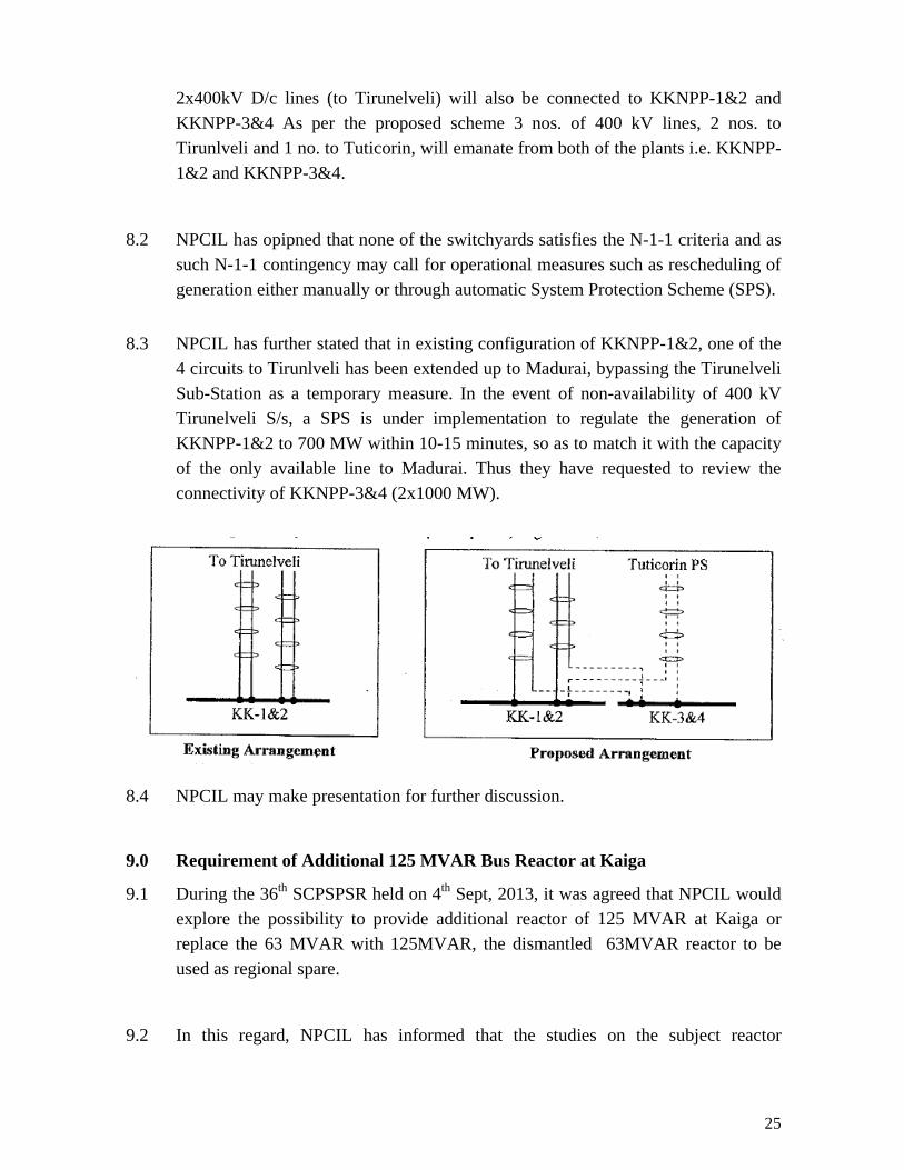
8.1 NPCIL vide their letter No. NPCIL/(Trans)/2014/M/27 dated May 19, 2014 (copy at Annex 8.1) has informed that connectivity arrangement for Kundnkulam -3&4 (\-3&4, 2x1000 MW) has been planned independently from that of the existing Kundankulam-1&2 (KKNPP-1&2, 2x1000 MW) due to current rating as well as switchgear rating limitations of 400kV switchyard of KKNPP-1&2. Under the proposed scheme, one additional 400kV D/C line has been planned to Tuticorin Pooling Station, one circuit of this D/C line would be connected to KKNPP 1&2 and the other to KKNPP 3&4. Similarly, one circuit of each of the existing
25
2x400kV D/c lines (to Tirunelveli) will also be connected to KKNPP-1&2 and KKNPP-3&4 As per the proposed scheme 3 nos. of 400 kV lines, 2 nos. to Tirunlveli and 1 no. to Tuticorin, will emanate from both of the plants i.e. KKNPP-1&2 and KKNPP-3&4.
8.2 NPCIL has opipned that none of the switchyards satisfies the N-1-1 criteria and as such N-1-1 contingency may call for operational measures such as rescheduling of generation either manually or through automatic System Protection Scheme (SPS).
8.3 NPCIL has further stated that in existing configuration of KKNPP-1&2, one of the
4 circuits to Tirunlveli has been extended up to Madurai, bypassing the Tirunelveli Sub-Station as a temporary measure. In the event of non-availability of 400 kV Tirunelveli S/s, a SPS is under implementation to regulate the generation of KKNPP-1&2 to 700 MW within 10-15 minutes, so as to match it with the capacity of the only available line to Madurai. Thus they have requested to review the connectivity of KKNPP-3&4 (2x1000 MW).
8.4 NPCIL may make presentation for further discussion.
9.0 Requirement of Additional 125 MVAR Bus Reactor at Kaiga
9.1 During the 36th SCPSPSR held on 4th Sept, 2013, it was agreed that NPCIL would explore the possibility to provide additional reactor of 125 MVAR at Kaiga or replace the 63 MVAR with 125MVAR, the dismantled 63MVAR reactor to be used as regional spare.
9.2 In this regard, NPCIL has informed that the studies on the subject reactor
26
requirement are under progress.
9.3 NPCIL may present the studies/status of studies. Members may discuss.
10.0 Reactive Compensation for Various Transmission Schemes approved in
previous SCMs
10.1 Reactive Compensation has been proposed for the following transmission Schemes approved in previous Standing Committee Meetings
i. Wardha – Hyderabad (Maheswaram)765 kV Link:
1 no. 240 MVAR, 765 kV Bus Reactors at Nizamabad. 1 no. 240 MVAR switchable line reactor at Maheshwaram and Wardha
for both circuits of Wardha – Hyderabad (Maheshwaram) 765kV D/c line with anchoring at Nizamabad.
1 no. 240 MVAR switchable line reactor at Nizamabad for both circuits of Wardha – Nizamabad 765kV D/c line and Nizamabad – Hyderabad (Maheshwaram) 765kV D/c line.
ii. Substation works associated with Hyderabad (Maheswaram) 765 kV Substation
2 nos. 240 MVAR, 765 kV Bus Reactors at Maheshwaram Pooling Station
iii. Sub-station Works associated with System Strengthening in Southern Region
for import of power from Eastern Region:
1 no. 240 MVAR switchable line reactor at Vemagiri Pooling Station and Srikakulam Pooling Station each for both circuits of Srikakulam PP – Vemagiri-II Pooling Station 765kV D/C line.
2 nos. 240 MVAR, 765 kV Bus Reactors at Vemagiri Pooling Station. 1 no. 80 MVAR, 400 kV Bus Reactors at Vemagiri Pooling Station.
iv. Transmission System associated with ISGS Projects in
Nagapattinam/Cuddalore Area of Tamilnadu – Part A1 (b)
1 no. 63 MVAR line reactor at Nagapattinam Pooling Station and Salem New (Dharmapuri) each for both circuits of Nagapttinam Pooling Station – Salem (New) 765 kV D/c line (initially charged at 400 kV) being implemented under Tariff based Bidding.
27
1 no. 63 MVAR line reactor at Madhugiri end of Salem New (Dharmapuri) – Madhugiri 765 kV S/c line (initially charged at 400 kV) being implemented under Tariff based Bidding.
v. GREN ENERGY CORRIDORS: ISTS-PART-A
2 no. 125 MVAR, 400 kV Bus Reactors at Tirunelveli Pooling Station.
10.2 System Studies were carried out for assessing Reactive Compensation for the above transmission Scheme and the results have been given at Annex 10.1.
10.3 Members may discuss and agree.
11.0 Establishment of 2x500 MVA, 400/230kV GIS S/S at Tirunelveli Pooling Station.
11.1 Regarding proposal for establishment of Tirunelveli Pooling Station of GIS type, PGCIL have informed that the total land requirement of GIS type is 16 acres as compared to 40 acres (including colony) for AIS type. They are planning to procure government land under control of Hindu Religious and Charitable Endowments Dept of TN at an estimated value of Rs 2 lakh per acre and in a lesser time frame. PGCIL has furnished substation layouts indicating land requirements for GIS and AIS types (Annex -11.1 and 11.2).
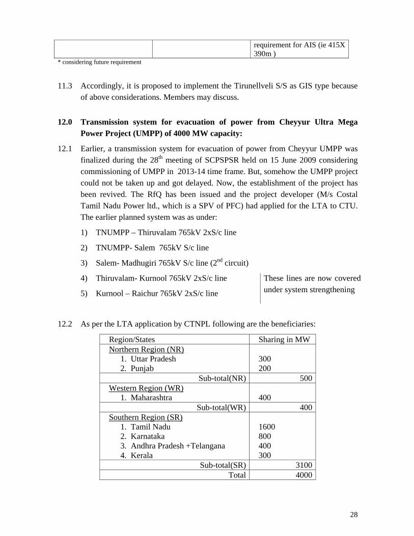
11.2 The comparative study between GIS and AIS at Trinellveli, as furnished by PGCIL, is given below:
Tirunelveli 400/230 kV new substation under Green Energy corridor Details GIS AIS No of 400KV diameters * 8 (4 for present scope) 8( 4 for present scope) 400KV Switch yard Scheme One and half breaker One and half breaker No of 400kV lines* 9 (4 in the present scope) 9(4 in the present scope) No of 400/230KV Transformer*
5 (2 in the present scope) 5(2 in the present scope)
No of bus reactors 2 (2 in the present scope) 2(2 in the present scope) No of line reactors * 3 (nil in the present scope) 3 (nil in the present scope) 220kV Switch yard scheme Double main Double main &transfer 220kV lines* 23(nil in the present scope) 23(nil in the present scope) Over all space requirement 16 acres for GIS (i.e
280m*225m) 35 acres for switch yard and 40 acres in total considering 5 acres for Township and open stores space
28
requirement for AIS (ie 415X 390m )
* considering future requirement
11.3 Accordingly, it is proposed to implement the Tirunellveli S/S as GIS type because of above considerations. Members may discuss.
12.0 Transmission system for evacuation of power from Cheyyur Ultra Mega
Power Project (UMPP) of 4000 MW capacity:
12.1 Earlier, a transmission system for evacuation of power from Cheyyur UMPP was finalized during the 28th meeting of SCPSPSR held on 15 June 2009 considering commissioning of UMPP in 2013-14 time frame. But, somehow the UMPP project could not be taken up and got delayed. Now, the establishment of the project has been revived. The RfQ has been issued and the project developer (M/s Costal Tamil Nadu Power ltd., which is a SPV of PFC) had applied for the LTA to CTU. The earlier planned system was as under:
1) TNUMPP – Thiruvalam 765kV 2xS/c line
2) TNUMPP- Salem 765kV S/c line
3) Salem- Madhugiri 765kV S/c line (2nd circuit)
4) Thiruvalam- Kurnool 765kV 2xS/c line These lines are now covered under system strengthening 5) Kurnool – Raichur 765kV 2xS/c line
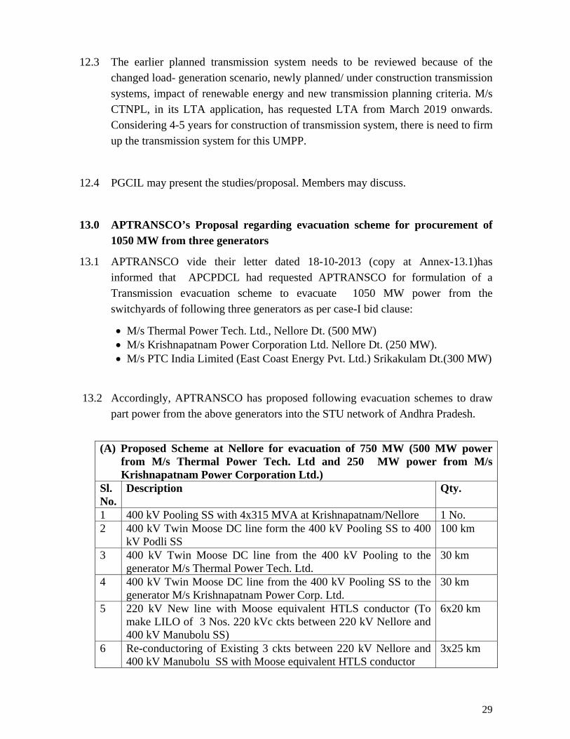
12.2 As per the LTA application by CTNPL following are the beneficiaries:
Region/States Sharing in MW Northern Region (NR)
1. Uttar Pradesh 2. Punjab
300 200
Sub-total(NR) 500 Western Region (WR)
1. Maharashtra 400
Sub-total(WR) 400 Southern Region (SR)
1. Tamil Nadu 2. Karnataka 3. Andhra Pradesh +Telangana 4. Kerala
1600 800 400 300
Sub-total(SR) 3100 Total 4000
29
12.3 The earlier planned transmission system needs to be reviewed because of the changed load- generation scenario, newly planned/ under construction transmission systems, impact of renewable energy and new transmission planning criteria. M/s CTNPL, in its LTA application, has requested LTA from March 2019 onwards. Considering 4-5 years for construction of transmission system, there is need to firm up the transmission system for this UMPP.
12.4 PGCIL may present the studies/proposal. Members may discuss.
13.0 APTRANSCO’s Proposal regarding evacuation scheme for procurement of 1050 MW from three generators
13.1 APTRANSCO vide their letter dated 18-10-2013 (copy at Annex-13.1)has informed that APCPDCL had requested APTRANSCO for formulation of a Transmission evacuation scheme to evacuate 1050 MW power from the switchyards of following three generators as per case-I bid clause:
• M/s Thermal Power Tech. Ltd., Nellore Dt. (500 MW) • M/s Krishnapatnam Power Corporation Ltd. Nellore Dt. (250 MW). • M/s PTC India Limited (East Coast Energy Pvt. Ltd.) Srikakulam Dt.(300 MW)
13.2 Accordingly, APTRANSCO has proposed following evacuation schemes to draw
part power from the above generators into the STU network of Andhra Pradesh.
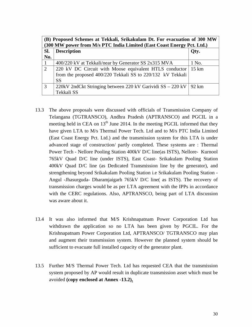
(A) Proposed Scheme at Nellore for evacuation of 750 MW (500 MW power
from M/s Thermal Power Tech. Ltd and 250 MW power from M/s Krishnapatnam Power Corporation Ltd.)
Sl. No.
Description Qty.
1 400 kV Pooling SS with 4x315 MVA at Krishnapatnam/Nellore 1 No. 2 400 kV Twin Moose DC line form the 400 kV Pooling SS to 400
kV Podli SS 100 km
3 400 kV Twin Moose DC line from the 400 kV Pooling to the generator M/s Thermal Power Tech. Ltd.
30 km
4 400 kV Twin Moose DC line from the 400 kV Pooling SS to the generator M/s Krishnapatnam Power Corp. Ltd.
30 km
5 220 kV New line with Moose equivalent HTLS conductor (To make LILO of 3 Nos. 220 kVc ckts between 220 kV Nellore and 400 kV Manubolu SS)
6x20 km
6 Re-conductoring of Existing 3 ckts between 220 kV Nellore and 400 kV Manubolu SS with Moose equivalent HTLS conductor
3x25 km
30
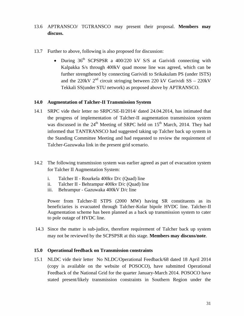
(B) Proposed Schemes at Tekkali, Srikakulam Dt. For evacuation of 300 MW (300 MW power from M/s PTC India Limited (East Coast Energy Pct. Ltd.) Sl. No.
Description Qty.
1 400/220 kV at Tekkali/near by Generator SS 2x315 MVA 1 No. 2 220 kV DC Circuit with Moose equivalent HTLS conductor
from the proposed 400/220 Tekkali SS to 220/132 kV Tekkali SS
15 km
3 220kV 2ndCkt Stringing between 220 kV Garividi SS – 220 kV Tekkali SS
92 km
13.3 The above proposals were discussed with officials of Transmission Company of
Telangana (TGTRANSCO), Andhra Pradesh (APTRANSCO) and PGCIL in a meeting held in CEA on 13th June 2014. In the meeting PGCIL informed that they have given LTA to M/s Thermal Power Tech. Ltd and to M/s PTC India Limited (East Coast Energy Pct. Ltd.) and the transmission system for this LTA is under advanced stage of construction/ partly completed. These systems are : Thermal Power Tech - Nellore Pooling Station 400kV D/C line(as ISTS), Nellore- Kurnool 765kV Quad D/C line (under ISTS), East Coast- Srikakulam Pooling Station 400kV Quad D/C line (as Dedicated Transmission line by the generator), and strengthening beyond Srikakulam Pooling Station i.e Srikakulam Pooling Station -Angul -Jhasurguda- Dharamjaigarh 765kV D/C line( as ISTS). The recovery of transmission charges would be as per LTA agreement with the IPPs in accordance with the CERC regulations. Also, APTRANSCO, being part of LTA discussion was aware about it.
13.4 It was also informed that M/S Krishnapatnam Power Corporation Ltd has withdrawn the application so no LTA has been given by PGCIL. For the Krishnapatnam Power Corporation Ltd, APTRANSCO/ TGTRANSCO may plan and augment their transmission system. However the planned system should be sufficient to evacuate full installed capacity of the generator plant.
13.5 Further M/S Thermal Power Tech. Ltd has requested CEA that the transmission system proposed by AP would result in duplicate transmission asset which must be avoided (copy enclosed at Annex -13.2).
31
13.6 APTRANSCO/ TGTRANSCO may present their proposal. Members may discuss.
13.7 Further to above, following is also proposed for discussion:
• During 36th SCPSPSR a 400/220 kV S/S at Garividi connecting with Kalpakka S/s through 400kV quad moose line was agreed, which can be further strengthened by connecting Garividi to Srikakulam PS (under ISTS) and the 220kV 2nd circuit stringing between 220 kV Garividi SS – 220kV Tekkali SS(under STU network) as proposed above by APTRANSCO.
14.0 Augmentation of Talcher-II Transmission System
14.1 SRPC vide their letter no SRPC/SE-II/2014/ dated 24.04.2014, has intimated that the progress of implementation of Talcher-II augmentation transmission system was discussed in the 24th Meeting of SRPC held on 15th March, 2014. They had informed that TANTRANSCO had suggested taking up Talcher back up system in the Standing Committee Meeting and had requested to review the requirement of Talcher-Gazuwaka link in the present grid scenario.
14.2 The following transmission system was earlier agreed as part of evacuation system for Talcher II Augmentation System:
i. Talcher II - Rourkela 400kv D/c (Quad) line ii. Talcher II - Behrampur 400kv D/c (Quad) line
iii. Behrampur - Gazuwaka 400kV D/c line Power from Talcher-II STPS (2000 MW) having SR constituents as its beneficiaries is evacuated through Talcher-Kolar bipole HVDC line. Talcher-II Augmentation scheme has been planned as a back up transmission system to cater to pole outage of HVDC line.
14.3 Since the matter is sub-judice, therefore requirement of Talcher back up system may not be reviewed by the SCPSPSR at this stage. Members may discuss/note.
15.0 Operational feedback on Transmission constraints
15.1 NLDC vide their letter No NLDC/Operational Feedback/68 dated 18 April 2014 (copy is available on the website of POSOCO), have submitted Operational Feedback of the National Grid for the quarter January-March 2014. POSOCO have stated present/likely transmission constraints in Southern Region under the
32
following categories:
ii) Transmission Lines Constraints iii) ICT Constraints iv) Nodes experiencing High Voltage and lines opened on high Voltage v) Delay in Generation affecting grid Operation adversely.
vi) Delay in Transmission Lines affecting grid Operation adversely
15.2 Transmission Lines constraints:
The SR has experienced high loading on Kolar-Hosur DC, S.V.Chathram- Pondy SC, Hosur-Salem both circuits, Salem-Udumalpet DC, Gooty-Nelamangala 400kV lines. POSOCO report also mentions about North-South corridor constraint in future.
These loading/constraints are likely to be eased with the already planned transmission system for strengthening of S1-S2 corridor.
SR grid has also experienced high loading on 400kV Hiriyur-Nelamangala DC line and Jindal-BTPS SC Line. These constraints are likely to be eased with commissioning of the transmission system planned for Yermaras TPS.
POSOCO report also states that there may be constraint in the 400kV Khammam-Nagarjunasagar SC line. A 400kV D/C line between Khammam and Nagarjun Sagar is already under construction.
Speeding up of the Kudamkulam Unit-1 & 2, Neyveli TPSII Exp Unit-1 and Neyveli TPSII Exp Unit-2 generation projects, as reported by POSOCO, would also provide relief in above constraints.
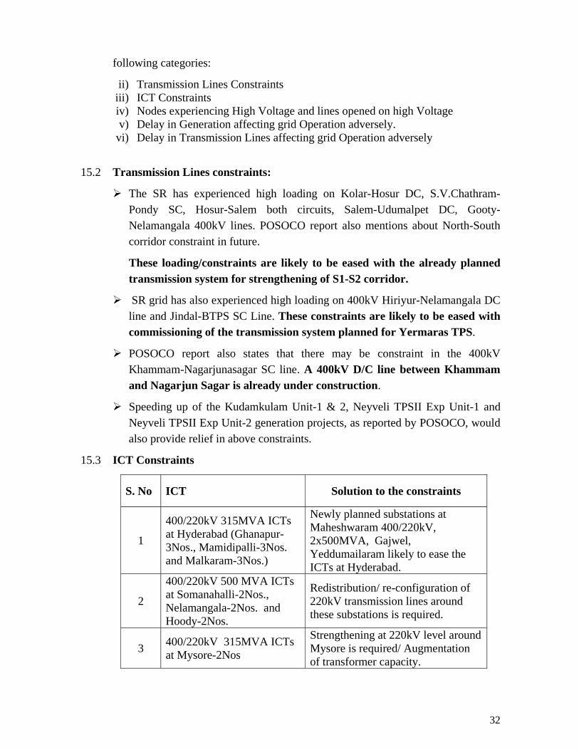
15.3 ICT Constraints
S. No ICT Solution to the constraints
1
400/220kV 315MVA ICTs at Hyderabad (Ghanapur-3Nos., Mamidipalli-3Nos. and Malkaram-3Nos.)
Newly planned substations at Maheshwaram 400/220kV, 2x500MVA, Gajwel, Yeddumailaram likely to ease the ICTs at Hyderabad.
2
400/220kV 500 MVA ICTs at Somanahalli-2Nos., Nelamangala-2Nos. and Hoody-2Nos.
Redistribution/ re-configuration of 220kV transmission lines around these substations is required.
3 400/220kV 315MVA ICTs at Mysore-2Nos
Strengthening at 220kV level around Mysore is required/ Augmentation of transformer capacity.

33
S. No ICT Solution to the constraints
4 400/220kV 315MVA ICTs at Kalvindapattu-2 Nos
Newly planned substations at Thiruvalam and Sholiangnalur would ease the ICTs at Kalvindapattu
5 400/220kV 315MVA ICTs at Trichur-2Nos and Palakkad-2Nos
Mysore- Kozikode 400kV line would ease the ICTs at Trichur.
15.4 Nodes experiencing high Voltages and lines opened on high voltage
High voltage on a number of 400kV nodes has been reported. The planned augmentation of bus reactors, including SVC/STATCOMs would help in bringing down the voltages. Further, regulating generation voltages and reactive absorption limits of generators need to be undertaken.
15.5 Delay in following transmission lines affecting grid operation adversely:
400kV Edaman-Cochin DC line400kV Mysore-Khozhikode DC lineNCTPS-II Evacuation: 400kV Alamathy-SV Chathram DC line and Alamathy-Tiruvalam DC lineStage-1 Wind evacuation system of TNEB: 400kv Kanarapatti SS, 400kV Kayathar SS, 400kV Tirunelvelli-Kanarpatti-Kayathar DC line,400kV Kayathar-Karaikudi-Pugalur DC line 400kV Kalvindapattu-Pugalur DC line and 400kV Tiruvalam-Mettur-III DC line
PGCIL, KSEB and TNEB may provide status of above transmission lines.
16.0 LTA/ Connectivity Agenda for discussion of POWERGRID
16.1 POWERGRID to present. Members may discuss.